Embed Size (px)
Citation preview

SL-45004-1/2” (11.43cm) 8K Lbs.-Ft. “Slim” Hydraulic Power Tong & Backup•Specifications•Operation•Maintenance•Assembly
TECHNICAL MANUAL
©2011 McCoy Corporation. All rights reserved.Published by McCoy Corporation, Technical Publications Department14755 - 121A Avenue • Edmonton, AB, Canada, T5L 2T2
mccoyglobal.com


SL4500 4-1/2” “SLim” Tong
SecTion conTenTS iii TechnicaL manuaL
This manual covers the following models:
NOTE: CE Marking available for all models except 80-2001-10. Some illustrations used in this manual may not exactly match your model of tong.
moDeL ReV DeScRiPTion80-2001-6 0 4-1/2”6500 lb.-ft. “Slim”Tongwith integratedbackup&supportstructure,standard2-armsling,motor
valve,backupvalve,&safetydoor.
80-2001-8 0 4-1/2”8000 lb.-ft. “Slim”Tongwith integratedbackup&supportstructure,standard2-armsling,motorvalve,backupvalve,liftvalve,&safetydoor.
80-2001-10 0 4-1/2”8000lb.-ft.“Slim”Tongwithintegratedbackup&supportstructure,short2-armsling,motorvalve,backupvalve,liftvalve,&safetydoor.
80-2001-13 0 4-1/2”8000 lb.-ft. “Slim”Tongwith integratedbackup&supportstructure,standard2-armsling,motorvalve,backupvalve,liftvalve,safetydoor,&dumpvalve
PATENTED & PATENTS PENDING

This page intentionallyleft blank

SL4500 4-1/2” “SLim” Tong
SecTion conTenTS v TechnicaL manuaL
WARNINGS
ANY REPLACEMENT FASTENER (BOLTS, NUTS, CAP SCREWS, MACHINE SCREWS, ETC.) USED DURING MAINTENANCE OR OVERHAUL MUST BE GRADE 8 OR EQUIVALENT UNLESS OTHERWISE SPECIFIED.
WHEN RE-ASSEMBLING LOAD-BEARING DEVICES (CHAIN SLINGS, RIGID SLINGS, BACKUP LEGS, ETC.) NOTE THAT THE ASSOCIATED FASTENERS MUST BE TIGHTENED TO THE CORRECT TORQUE SPECIFIED FOR THAT SIZE OF FASTENER (SEE SECTION 3 - OVERHAUL). ANY THREADED FASTENER IN A LOAD-BEARING DEVICE MUST BE SECURED WITH RED OR BLUE LOCTITE™.
A “LOAD-BEARING DEVICE” IS A CHAIN SLING, RIGID SLING, SPREADER BAR ASSEMBLY, FRAME, OR ANY OTHER DEVICE THAT BEARS THE PARTIAL OR TOTAL WEIGHT OF THE EQUIPMENT FOR WHICH THIS MANUAL HAS BEEN PRODUCED
THE LOAD-BEARING DEVICE SUPPLIED BY MCCOY DRILLING & COMPLETIONS IS DESIGNED TO SUP-PORT THE EQUIPMENT DESCRIBED IN THIS MANUAL. MCCOY DRILLING & COMPLETIONS WILL NOT GUARANTEE THE ABILITY OF THE LOAD-BEARING DEVICE TO SUPPORT ANY OTHER PART, ASSEM-BLY OR COMBINATION OF PARTS AND ASSEMBLIES. MCCOY DRILLING & COMPLETIONS WILL NOT GUARANTEE THE ABILITY OF THE LOAD-BEARING DEVICE TO LIFT OR SUPPORT THE EQUIPMENT DESCRIBED IN THIS MANUAL IF THERE ARE ANY MODIFICATIONS TO THE LOAD-BEARING DEVICE, OR ANY ADDITIONS TO THE EQUIPMENT DESCRIBED IN THIS MANUAL THAT ADD WEIGHT TO THE EQUIPMENT, UNLESS SUPPLIED BY MCCOY DRILLING & COMPLETIONS.

This page intentionallyleft blank
SL4500 4-1/2” “SLim” Tong
SecTion conTenTS vii TechnicaL manuaL
Summary Of RevisionsDate Section Page Description Of Revision
May2009 N/A N/A InitialRelease
Sep2009 Intro 1.2&1.3 Correcteddimensionsonthespecificationpages
May2010 Varies Varies Updatedillustrationsthroughouttorepresentupdatedjawretentionmechanism,updatedlogosandbranding
June2010 Varies Varies UpdatedmanualtocomplywithCEmarking
September2010 Appendixes Varies Revisedappendixes
December2011
All All Addedtableofillustrations
2 2.13 Revisedsubsection2.F.1,“TongRig-Up&Leveling,Suspension&Restraint”
2 2.17 Insertedsubsection2.G.1,“TongOperation,OperatorTraining”
2 2.21 RemovedSections2.J&2.K,“MakingUpAJoint”and“BreakingOutAJoint”,insertedsection2.I,“Making&BreakingAConnection”.
3 3.1 RevisedSection3.A,“GeneralMaintenanceSafetyPractices”.
3 3.1 InsertedSection3.C,“PreventiveMaintenancePractices”.
3 3.6 InsertedSubsection3.E.2,“SafetyDoorSwitchAdjustment”.
3 3.16 Moved“DailyPowerTongInspection&MaintenanceChecklist”toMaintenancesection.
3 3.18 Moved“MonthlyPowerTongInspection&MaintenanceChecklist”toMaintenancesection.
3 3.21 Moved“DailyBackupInspection&MaintenanceChecklist”toMaintenancesec-tion.
3 3.22 Moved“DailyPowerUnitInspection&MaintenanceChecklist”toMaintenancesection.
3 3.23 Moved“TubularConnectionEquipmentDe-commissioningChecklist”toMainte-nancesection.
3 3.26 Moved“TubularConnectionEquipmentRe-commissioningChecklist”toMainte-nancesection.
4 4.1-4.6 Revised“Troubleshooting”section.
6 ALL Completerevisionoftorquemeasurementsection
Copyright©2009-2011McCoyCorporation,includingitswhollyownedsubsidiaries,(“McCoy”),allrightsreserved.ThisdocumentisthepropertyofMcCoyandissuppliedasreferenceinformationforusersofourproducts.Thisdocumentandthecontentswithinareconsid-eredconfidentialinformation,nottobedisclosed,copied,transmitted,transcribedinanyform,orstoredonanytypeofdatastoragemediawithouttheexpresswrittenconsentofMcCoy.McCoyhasmadeeveryefforttoensuretheinformationcontainedinthisdocumentisaccurateandcurrent.Thismanualisintendedtoprovideequipmentoperationandsafetyinstructionsforyourequipment.However,McCoydoesnotwarrantorguaranteethattheinforma-tioniseithercompleteoraccurateineveryrespectandtheuserofthemanualshouldconsultwithitsMcCoysalesrepresentativeforanyclarificationsandupdates.Theuserofthemanualshallprotect,indemnify,andholdharmlessMcCoyanditsdirectors,officers,employees,andagentsfromandagainstallliabilityforpersonalinjury,death,orpropertydamageresultingdirectlyorindirectlyfromtheuseoftheinformationcontainedinthismanual.Observanceofalldescriptions, informationand instructionssetout in thismanual is thefull responsibilityof theuser.Thismanual isintendedforguidanceandinformationalpurposesandmustbeusedinassociationwithadequatetrainingandon-the-jobsupervisiontoprovidesafeandeffectiveequipmentuse.Itistheresponsibilityoftheusertoconformtoallregulationsandrequirementsissuedbyanauthorityoragencywhichmayaffecttheoperation,safetyorequipmentintegrity,thatmayoverrulethecontentofthisdocumentation.Theuserwillacknowledgeandobeyanygenerallegalorothermandatoryregulationinforcerelatingtoaccidentprevention,safety,andequipmentintegrity.

SL4500 4-1/2” “SLim” Tong
SecTion conTenTSviii TechnicaL manuaL
Introduction & Specifications .................................................................................................................................... Section One Introduction&ContactInformation....................................................................................................................... 1.1 EquipmentSpecifications..................................................................................................................................... 1.2 LubricationSpecifications..................................................................................................................................... 1.4Setup & Operation ...................................................................................................................................................... Section Two Sling/LoadBearingDeviceSafety...................................................................................................................... 2.1 MajorComponentIdentification............................................................................................................................ 2.4 HydraulicSchematic/HydraulicValveIdentification........................................................................................... 2.8 HydraulicConnections......................................................................................................................................... 2.11 Tong/BackupJawAvailability&Installation....................................................................................................... 2.12 TongRig-Up&Leveling....................................................................................................................................... 2.13 TongOperation.................................................................................................................................................... 2.17 ExtremeColdWeatherOperationProcedures..................................................................................................... 2.20 Making&BreakingConnections.......................................................................................................................... 2.21Maintenance ................................................................................................................................................................ Section Three GeneralMaintenanceSafetyPractices................................................................................................................ 3.1 Cleaning............................................................................................................................................................... 3.1 PreventiveMaintenance....................................................................................................................................... 3.1 Lubrication............................................................................................................................................................ 3.2 Adjustments.......................................................................................................................................................... 3.5 RecommendedPeriodicChecks.......................................................................................................................... 3.7 Disassembly&OverhaulProcedures................................................................................................................... 3.8 AssemblyInstructions.......................................................................................................................................... 3.9 DailyInspection&MaintenanceChecklist(PowerTong)..................................................................................... 3.16 MonthlyInspection&MaintenanceChecklist(PowerTong)................................................................................ 3.18 DailyInspection&MaintenanceChecklist(Backup)............................................................................................ 3.21 DailyInspection&MaintenanceChecklist(PowerUnit)...................................................................................... 3.22 TubularConnectionEquipmentDe-commissioningProcedures.......................................................................... 3.23 TubularConnectionEquipmentRe-commissioningProcedures.......................................................................... 3.26Troubleshooting ......................................................................................................................................................... Section Four TongWillNotDevelopSufficientTorque............................................................................................................. 4.1 FailureOfJawsToGripPipe............................................................................................................................... 4.3 TongRunningTooSlowly.................................................................................................................................... 4.4 GeneralComments.............................................................................................................................................. 4.5Assemblies And Parts ............................................................................................................................................... Section Five GearTrain............................................................................................................................................................ 5.2 IdlerAssemblies................................................................................................................................................... 5.4 ReductionGearAssembly(Small)....................................................................................................................... 5.6 ReductionGearAssembly(Large)....................................................................................................................... 5.8 RotaryAssembly.................................................................................................................................................. 5.10 RotaryGearAssembly......................................................................................................................................... 5.12 TongBodyAssembly........................................................................................................................................... 5.14 HydraulicAssembly.............................................................................................................................................. 5.16 MotorAssembly.................................................................................................................................................... 5.18 BrakeBands......................................................................................................................................................... 5.20 DoorAssembly..................................................................................................................................................... 5.22 RigidSlingAssembly............................................................................................................................................ 5.24 BackupAssembly................................................................................................................................................. 5.26 RearLegAssembly.............................................................................................................................................. 5.28 FrontLegAssemblies........................................................................................................................................... 5.30Torque Measurement ................................................................................................................................................. Section SixHydraulic Component Information ........................................................................................................................... Section Seven
TabLe of conTenTS

SL4500 4-1/2” “SLim” Tong
SecTion conTenTS ix TechnicaL manuaL
Illustration1.A.1:SL4500Tong&Backup.................................................................................................................................... 1.1Illustration1.A.2:SL4500Dimensions.......................................................................................................................................... 1.2Illustration2.A.1:SlingAngle........................................................................................................................................................ 2.1Illustration2.B.1:ComponentIdentification01............................................................................................................................. 2.4Illustration2.B.2:ComponentIdentification02............................................................................................................................. 2.5Illustration2.B.3:ComponentIdentification03............................................................................................................................. 2.6Illustration2.B.4:ComponentIdentification04............................................................................................................................. 2.6Illustration2.B.5:ComponentIdentification05............................................................................................................................. 2.7Illustration2.C.1:HydraulicSchematic01.................................................................................................................................... 2.8Illustration2.C.2:HydraulicComponentIdentification01............................................................................................................. 2.9Illustration2.C.3:HydraulicComponentIdentification02............................................................................................................. 2.9Illustration2.C.4:HydraulicComponentIdentification03............................................................................................................. 2.10Illustration2.D.1:HydraulicConnections01................................................................................................................................. 2.11Illustration2.D.2:HydraulicConnections02................................................................................................................................. 2.11Illustration2.E.1:TongJawRemoval........................................................................................................................................... 2.12Illustration2.E.2:TongJawDieReplacement.............................................................................................................................. 2.13Illustration2.F.1:MasterLink....................................................................................................................................................... 2.14Illustration2.F.2:TongLeveling................................................................................................................................................... 2.15Illustration2.F.3:LoadCellConfiguration.................................................................................................................................... 2.16Illustration2.G.1:TongMotorControl.......................................................................................................................................... 2.18Illustration2.G.2:LiftCylinderControl.......................................................................................................................................... 2.18Illustration2.G.3:BackupClampControl..................................................................................................................................... 2.19Illustration2.G.4:MotorSpeedControl........................................................................................................................................ 2.19Illustration2.I.1:TongSuspension-MasterLink......................................................................................................................... 2.21Illustration2.I.2:SettingBackingPinto“Make-up”....................................................................................................................... 2.22Illustration2.I.3:BackupControl................................................................................................................................................... 2.22Illustration2.I.4:CLAMPPressureGaugeonGaugePanel......................................................................................................... 2.23Illustration2.I.5:BackupPressureControlValve......................................................................................................................... 2.23Illustration2.I.6:Unlatching&OpeningDoor............................................................................................................................... 2.24Illustration2.I.7:LiftCylinderControl............................................................................................................................................ 2.25Illustration2.I.8:BackupControl................................................................................................................................................... 2.26Illustration2.I.9:MotorSpeedControl.......................................................................................................................................... 2.26Illustration2.I.10:RotationControl-Makeup............................................................................................................................... 2.27Illustration2.I.11:Torque&SystemPressureGaugesonGaugePanel..................................................................................... 2.27Illustration2.I.12:SwitchingMotorspeedSwitchToLOWSPEED.............................................................................................. 2.28Illustration2.I.13:ReversingRotationToFreeTongJaws........................................................................................................... 2.28Illustration2.I.14:Un-clampingBackupJaws............................................................................................................................... 2.29Illustration2.I.15:LoweringAssemblyUsingLiftCylinderControl............................................................................................... 2.29Illustration2.I.16:SettingBackingPinTo“Break-out”Mode........................................................................................................ 2.30Illustration2.I.17:RotationControl-Break-out............................................................................................................................ 2.31Illustration2.I.18:SwitchingMotorSpeedControlToHIGHSPEED........................................................................................... 2.32Illustration2.I.19:ReleasingTongJawsFollowingBreakOut&Un-threading............................................................................ 2.32Illustration2.I.20:Un-clampingBackupJaws............................................................................................................................... 2.33Illustration2.I.21:LoweringAssemblyUsingLiftCylinderControl............................................................................................... 2.33Illustration3.D.1:CagePlateRollerLubrication........................................................................................................................... 3.2Illustration3.D.2:IdlerShaftBearingLubrication......................................................................................................................... 3.2Illustration3.D.3:ReductionGearBearingLubrication................................................................................................................ 3.3Illustration3.D.4:DoorPivotShaftLubrication............................................................................................................................. 3.3Illustration3.D.5:DoorLatch&PostLubrication.......................................................................................................................... 3.4Illustration3.D.6:JawAssemblyLubrication................................................................................................................................ 3.4Illustration3.D.7:LoadCellLubrication........................................................................................................................................ 3.5Illustration3.E.1:BrakeBandAdjustment.................................................................................................................................... 3.5Illustration3.E.2:SafetyDoorPlungerAdjustment01................................................................................................................. 3.6Illustration3.E.3:SafetyDoorPlungerAdjustment02................................................................................................................. 3.6Illustration3.E.4:SafetyDoorPlungerAdjustment03................................................................................................................. 3.7Illustration3.H.1:GearboxCoverInstallation............................................................................................................................... 3.10Illustration3.H.2:IdlerGearInstallation....................................................................................................................................... 3.11Illustration3.H.3:RotaryGearAssembly..................................................................................................................................... 3.11Illustration3.H.4:“ButtonGuide”Installation................................................................................................................................ 3.12Illustration3.H.5:MainBodyFastenerPlacement....................................................................................................................... 3.12Illustration3.H.6:DoorLatchWeldmentInstallation..................................................................................................................... 3.13Illustration3.H.7:DoorDetentInstallation.................................................................................................................................... 3.14Illustration6.A.1:TorqueGauge................................................................................................................................................... 6.1Illustration6.A.3:CompressionLoadCell.................................................................................................................................... 6.1Illustration6.A.2:TensionLoadCell............................................................................................................................................. 6.1Illustration6.A.4:TensionLoadCellExploded............................................................................................................................. 6.3Illustration6.A.5:CompressionLoadCellExploded.................................................................................................................... 6.4Illustration6.A.6:TurnCounterEncoderMountExploded........................................................................................................... 6.5
LiST of iLLuSTRaTionS

SL4500 4-1/2” “SLim” Tong
SecTion conTenTSx TechnicaL manuaL
IDENTIFICATION OF OF WARNINGS AND OTHER NOMENCLATURE OF IMPORTANCE USED IN THIS INSTALLATION GUIDE
FarrCanadaCorp.usesthreeindicatorstodescribeitemsofthreedegreesofimportance.
AHAZARD tooperatorsorequipment is representedbyanexclamationpointwithina red triangleand identifies itemsofthehighestimportance.FailuretoheedinformationidentifiedbyaHAZARDsymbolmayresultinbodilyinjury,death,catastrophicequipmentdamage,oranycombinationofthese.AHAZARDmayalsoindicatethepotentialfordangerousenvironmentalcontamination.
Theinformationpresentedinthisdocumentwillprovidesetup,operating,andmaintenanceinstructionsforyourSL4500tong.Duetothewidevarietyofoperatingconditions,theseinstructionsmustbeconsideredguidelinesratherthanabsoluteoperatingprocedures.Itistheresponsibilityoftheusertousetheseguidelinestogetherwithanexperiencedmanagertodevelopoperatingproceduresthatconformtoallpoliciessetforthbytheop-eratingauthority(ies).
AWARNINGisrepresentedbyanexclamationpointwithinanorangetriangle,andcontainsinformationthatwillalertper-sonneltoapotentialsafetyhazardthatisnotlife-threatening.AWARNINGmayalsoservetoalerttheusertoinformationcriticaltothecorrectassemblyoroperationoftheequipmentinuse.
This identifies a HAZARD to operators or equipment
This identifies a WARNING to users
ACAUTIONisrepresentedbyanexclamationpointwithinayellowtriangleandhighlightsinformationthatmayaidtheuserduringassemblyoroperationofyourequipment.CAUTIONsarealsousedtoensurecommonerrorsarenotmadeduringassemblyoroperationofyourequipment.
This identifies a CAUTION to users
Observance of the following is the full responsibility of the user:
● all descriptions, information and instructions set out in this manual● any regulation or requirement issued by an authority or agency which may influence operation,
safety or integrity of the equipment that overrules the content of this document.● any legal or other mandatory regulation in force governing accident prevention or environmental
protection.

SL4500 4-1/2” “SLim” Tong
SecTion conTenTS 1.1 TechnicaL manuaL
inTRoDucTion
CongratulationsonthepurchaseofyourFARR®SL45004-1/2”“Slim”tong.Thisunitwillprovideyouwithyearsofoutstandingperfor-mance.Simplemaintenanceandcarewillextenditslifeandensureyearsofexcellentperformanceandreliability.Thesetup,operating,andmaintenanceinstructionsinthismanualwillassistyouingivingyourequipmentthecareitrequires.Pleasecarefullyreadthemanualbeforeinstallingandusingyourequipment.ReplacementpartsarereadilyavailablefromMcCoyDrilling&Completions|FARRinEdmon-tonAlberta.NotethatmanypartsaretransferablebetweenFARR®tongsandbackups.Shouldyouneedreplacementparts,orshouldyouexperienceanydifficultynotcoveredinthismanual,pleasecontact:
McCoy Drilling & Completions | FARR14755121AAvenueEdmonton,AlbertaCanadaT5L2T2
Phone:780.453.3277Fax:780.455.2432
SalesFax:780.481.9246EmailEngineering:[email protected]:[email protected]
Website:http://www.mccoyglobal.com/index.php/drilling-completions
IllustratIon 1.a.1: sl4500 tong & Backup
SL4500 4-1/2” “SLim” Tong
SecTion conTenTS1.2 TechnicaL manuaL
SPecificaTionS
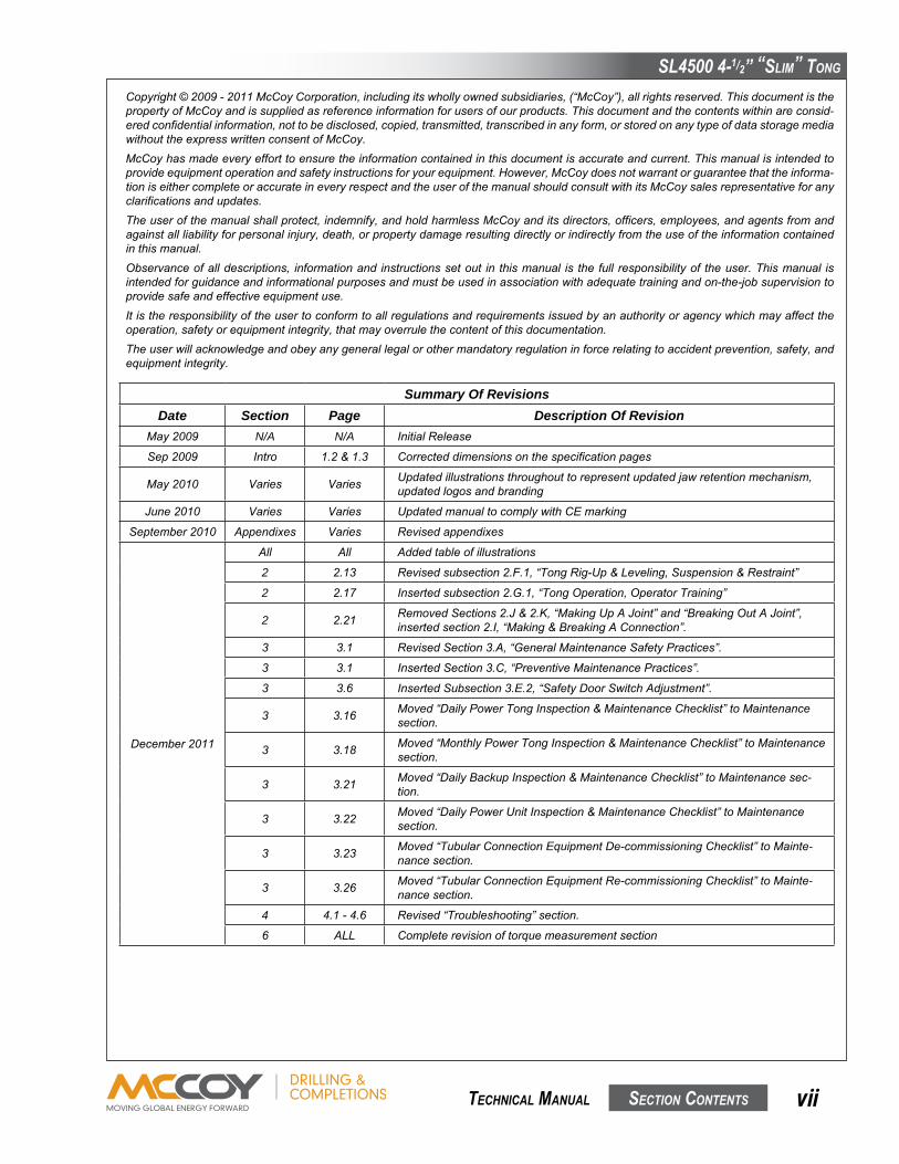
PLEASE NOTE: AREAS SHOWN HIGHLIGHTED ARE POTENTIAL PINCH/HAZARD AREAS. EXERCISE CAUTION AROUND THESE AREAS DURING TONG OPERATION.
IllustratIon 1.a.2: sl4500 DImensIons
20”
39-7/8”
48-1/2”

SL4500 4-1/2” “SLim” Tong
SecTion conTenTS 1.3 TechnicaL manuaL
SPecificaTionS
** These are ideal values. Actual achieved torque is highly dependant upon tong efficiency and final position of rotary gear when full torque load is reached.
Max. Hydraulic Requirements: 60GPM(227.1LPM)/3000PSI(20.684MPa) Max Hydraulic Fluid Temp: 82°C Operating Temperature: -20°Cto+40°C Length: 39-7/8”/101.3cm Overall Width: 20”/50.8cm Height: 48-1/2”/123.2cm Torque arm length: 24-3/4inches/62.9cm(Tongonly)(CenterLineofPipeCenterLineofAnchorHandle) 18inches/45.7cm(Tong&Backup) Weight (Approximate): 600lb./273kg.(TongOnly) 1000lb./444.4kg.(Tong&Backup) Jaw Range: 1.90”(48.25mm)-5.00”(127mm)DiameterPipe Jaws available (inches): SeePp.2.13 Max Sound Level: 97dBA@1m 96dBC@1m
Torque Table (Low Torque) **Pressure (PSI) Hi Speed (lbs.-ft.) Lo Speed (lbs.-ft.)
1000 660 2300
1500 1060 3700
2000 1485 5200
2500 1885 6500
MAXIMUM RATED TORQUE: 6500 LBS.-FT.
Speed Table (Low Torque) **Flow (US GPM) Lo Speed (RPM) Hi Speed (RPM)
10 8 28
20 16 55
40 32 111
60 48 166
Torque Table (High Torque) **Pressure (PSI) Hi Speed (lbs.-ft.) Lo Speed (lbs.-ft.)
1000 1400 2800
1500 2300 4600
2000 3150 6300
2500 4000 8000
MAXIMUM RATED TORQUE: 8000 LBS.-FT.
Speed Table (High Torque) **Flow (US GPM) Lo Speed (RPM) Hi Speed (RPM)
10 6 13
20 13 25
40 26 51
60 39 76
replacement fasteners (Bolts, nuts, cap screws, machIne screws, etc.) must Be graDe 8 or equIvalent unless otherwIse specIfIeD.

SL4500 4-1/2” “SLim” Tong
SecTion conTenTS1.4 TechnicaL manuaL
UseanEPsyntheticgreasethatmeetsorexceedsthefollowingspecifications:
Thickener LithiumComplex NLGIconsistencygrade 2 NLGIperformancegrade GC-LB Penetration-ASTMD217(25°C[77°F] 265-295minimum 0.1mm)worked60strokes Droppingpoint,°F[°C]-ASTMD2265 550[288]minimum Hightemperaturelife,hours-ASTMD3527 160minimum Oxidationstability,psi-ASTMD942 (100hr/300hr)0/3 Waterwashout,percent-ASTMD1264 1.8max Rustandcorrosion-ASTMD1743 pass Oilseparation,percentloss-ASTMD1742 1.1max (24hours,25°C[77°F] Leakage,glost-ASTMD4290 1.0max Fourballweartest,mmscar-ASTMD2266 0.40max Frettingwear,mg-ASTMD4170 3.4max FourballEP,kgf-ASTMD2596 Weldpoint 400minimum Loadwearindex 50minimum TimkenOKloadtest,lbs-ASTMD2509 50 Lowtemperaturetorque,N*m-ASTMD4693 1.3max (-40°C[-40°F]) LT-37pumpability,g/min 360/7 (60°F/0°F[16°C/-18°C]) Coppercorrosion-ASTMD4048 1B Discbrakewheelbearingspecifications FordESA-M1C198A Yes ChryslerMS-3701 Yes Oilviscosity:40°C[104°F],cSt 151 100°C[212°F],cSt 19.2 Flashpoint,°F[°C]-ASTM92 450[232]
Useapremiumqualityhydraulicfluidthatmeetsorexceedsthefollowingspecifications:
TypicalDensity(kg/m3) 878 Viscosity-cSt@40°C 68.8 -cSt@100°C 8.7 ViscosityIndex 97 PourPoint°F[°C] -22[-30] FlashPoint°F[°C] 432[222] Colour,ASTM 1.5 NeutralizationNumber 0.40 RustProtection-DistilledWater NoRust -SeaWater NoRust HydrolyticStability-CuMassLoss,mg/cm2 0.04 CopperCorrosionTest 1A Filterability:Denison-Wet&Dry Pass Afnor-Wet&Dry Pass CincinattiMilacronSpecApproved P69 DenisonHF-0: Approved DenisonP-46PistonPump: Pass DenisonT6CVanePump: Pass Vickers35VQ25VanePumpTest: Pass 104/105CVanePumpTest: NoDataAvailable Vanepumptesttotalringandvanewear,mg. <10 OxidationStability TurbineOilStabilityTestLife,hours 2500+ RotaryBombOxidationTest,minutes 325 FZGSpurGearTest,FailureLoadStage(FLS) 12
SPecificaTionS
SL4500 4-1/2” “SLim” Tong
SecTion conTenTS 2.1 TechnicaL manuaL
SeTuP & oPeRaTion
McCoyDrilling&Completionsrecommendsfollowinganindustry-acceptedstandardsuchasOSHA,ASMEB30.9-2006,ormanu-facturer’sguidelineswhenperforminganyriggingandoverhead lifting.Usebyuntrainedpersons ishazardous. Improperusewillresultinseriousinjuryordeath.Donotexceedratedcapacity.Slingswillfailifdamaged,abused,misused,overused,orimproperlymaintained.
● Onlygrade80orgrade100alloychainshouldbeusedforoverheadliftingapplications.● WorkingLoadLimit(WLL)isthemaximumallowableloadinpoundswhichmaybeappliedtotheload-bearingdevice,whenthedeviceisneworin“asnew”condition,andwhentheloadisuniformlyanddirectlyapplied.TheWLLmustneverbeexceeded.
● WorkingLoadLimit(WLL)isthemaximumworkingloadforaspecificminimumslingangle,measuredfromthehorizontalplane.TheWorkingLoadLimitisidentifiedonthesling.
● TheWorkingLoadLimitorDesignfactormaybeaffectedbywear,misuse,overloading,corrosion,deformation,intentionalal-terations,sharpcornercuttingactionandotheruseconditions.
● Shockloadingandextraordinaryconditionsmustbetakenintoaccountwhenselectingalloychainslings.● SeeOSHARegulation for Slings 1910.184,ANSI/ASMEB30.9-”SLINGS”,ANSI/ASMEB30.10-”HOOKS” and ANSI/AMSEB30.26“RIGGINGHARDWARE”foradditionalinformation.
DO NOT ACCESS ROTATING COMPONENTS UNLESS HYDRAULIC POWER SUPPLY HAS BEEN DEACTIVATED OR ISOLATED.
A CLEARLY IDENTIFIED REMOTE POWER PACK EMERGENCY STOP MUST BE INSTALLED IN THE IMMEDIATE VICINITY OF THE TONG OPERATOR.
Adequatesetupandproperhydraulicconnectionsareessentialinensuringreliableoperationofyourtong.Forbestresultsandlongtermreliability,readandobeythestart-upinstructionsinthissection.
THE SUPPLIED LOAD-BEARING DEVICE (CHAIN SLING, RIGID SLING, SPREADER BAR ASSEM-BLY, FRAME, OR ANY OTHER DEVICE THAT BEARS THE PARTIAL OR TOTAL WEIGHT OF THE EQUIPMENT DESCRIBED IN THIS MANUAL) HAS BEEN SPECIFIED OR DESIGNED TO SUPPORT THE EQUIPMENT DESCRIBED IN THIS DOCUMENT. FARR WILL NOT GUARANTEE THE ABILITY OF THE LOAD-BEARING DEVICE TO SUPPORT ANY OTHER PART, ASSEMBLY OR COMBINA-TION OF PARTS AND ASSEMBLIES, OR ANY ADDITIONS TO THE EQUIPMENT DESCRIBED IN THIS MANUAL THAT ADD WEIGHT TO THE EQUIPMENT, UNLESS SUPPLIED BY FARR CANADA CORP..
FARR CANADA CORP. DOES NOT GUARANTEE THE INTEGRITY OF MODIFIED OR DAMAGED LOAD-BEARING DEVICES, UNLESS THOSE MODIFICATIONS ARE PERFORMED BY FARR CAN-ADA CORP..
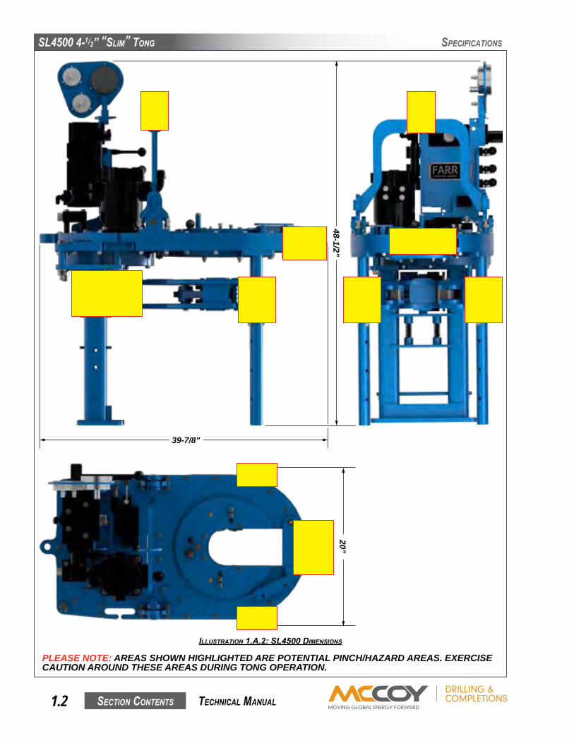
THE MINIMUM SLING ANGLE (THE ANGLE OF THE LEG OF THE SLING MEASURED FROM THE HORIZONTAL) MUST NEVER FALL LOWER THAN THE ANGLE SPECIFIED FOR THE SLING IN USE
A. SLING / LOAD BEARING DEVICE SAFETY
IllustratIon 2.a.1: slIng angle
Sling Angle
SL4500 4-1/2” “SLim” Tong
SecTion conTenTS2.2 TechnicaL manuaL
SeTuP & oPeRaTion
1. Inspection Of Slings Farr Canada Corp. strongly recommends the following practices:
Acompleteinspectionofnewload-bearingdevicesandattachmentsshallbeperformedbyaqualified,designatedpersonpriortoinitialuse.Eachlinkandcomponentshallbeexaminedindividually,takingcaretoexposeandexamineallsurfacesincludingtheinnerlinksurface.Theslingshallbeexaminedforconditionssuchasthoselistedintheremovalcriteriabelow.Inaddition,dailyinspectionofslings,fasteningsandattachmentsshallbeperformedbyadesignatedperson.Ifdamageordefectsarefoundateitherinspection,thedamagedordefectivecomponentshallbequarantinedfromserviceuntilitcanbeproperlyrepairedorreplaced.
RemovalCriteria:
Aload-bearingdeviceshallberemovedfromserviceifconditionssuchasthefollowingarepresent:● Missingorillegibleslingidentification.● Cracksorbreaks● Evidenceoftamperingisseen-slingtaghasbeenmodifiedorobscured,ortamper-proofnutsaremissing.● Signsofimpactonload-bearingcomponents,includingspreaderbars,liftinglugs,rigidslings&rigidslingweldments,andlegs&legmounts.
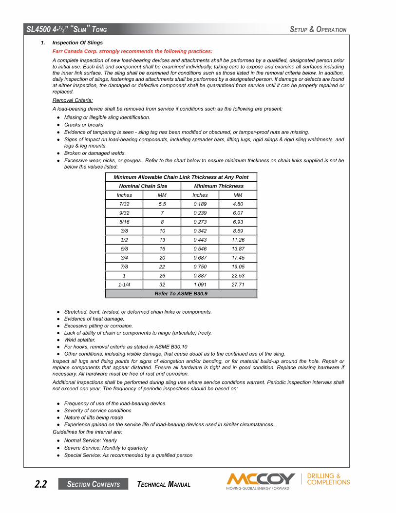
● Brokenordamagedwelds.● Excessivewear,nicks,orgouges.Refertothechartbelowtoensureminimumthicknessonchainlinkssuppliedisnotbebelowthevalueslisted:
Minimum Allowable Chain Link Thickness at Any PointNominal Chain Size Minimum ThicknessInches MM Inches MM
7/32 5.5 0.189 4.80
9/32 7 0.239 6.07
5/16 8 0.273 6.93
3/8 10 0.342 8.69
1/2 13 0.443 11.26
5/8 16 0.546 13.87
3/4 20 0.687 17.45
7/8 22 0.750 19.05
1 26 0.887 22.53
1-1/4 32 1.091 27.71
Refer To ASME B30.9
● Stretched,bent,twisted,ordeformedchainlinksorcomponents.● Evidenceofheatdamage.● Excessivepittingorcorrosion.● Lackofabilityofchainorcomponentstohinge(articulate)freely.● Weldsplatter.● Forhooks,removalcriteriaasstatedinASMEB30.10● Otherconditions,includingvisibledamage,thatcausedoubtastothecontinueduseofthesling.
Inspectall lugsand fixingpoints for signsof elongationand/orbending, or formaterial build-uparound thehole.Repair orreplacecomponents that appeardistorted.Ensureall hardware is tight and ingoodcondition.Replacemissinghardware ifnecessary.Allhardwaremustbefreeofrustandcorrosion.
Additionalinspectionsshallbeperformedduringslingusewhereserviceconditionswarrant.Periodicinspectionintervalsshallnotexceedoneyear.Thefrequencyofperiodicinspectionsshouldbebasedon:
● Frequencyofuseoftheload-bearingdevice.● Severityofserviceconditions● Natureofliftsbeingmade● Experiencegainedontheservicelifeofload-bearingdevicesusedinsimilarcircumstances.
Guidelinesfortheintervalare:● NormalService:Yearly● SevereService:Monthlytoquarterly● SpecialService:Asrecommendedbyaqualifiedperson

SL4500 4-1/2” “SLim” Tong
SecTion conTenTS 2.3 TechnicaL manuaL
SeTuP & oPeRaTion
UnitsdesignedandmanufacturedinaccordancewithEN12079andDNV2.7-1shouldbetestedandexaminedinaccordancewiththefollowingscheduleofexaminationandtest.Theuseroftheload-bearingdeviceshallplaceapermanentplacardorplateuponwhichthetypeanddateofthelasttestshallberecorded.Toavoidconfusion,theplateshallnotcarrythedateofthenexttestorexamination,onlythemostrecent.
Test / Examination
Time / inTerval lifTing TesTs1
non-DesTrucTive examinaTion (nDe) of
lifTing PoinTs
Thorough visual
examinaTion
suffix To Be markeD on PlaTe aTTacheD
To uniT
InitialCertificationByFarr/Superior YES YES YES T
IntervalNotExceeding12Months
Atthediscretionofinspectionbody
Atthediscretionofinspectionbody YES TorVN3
IntervalNotExceeding60Months
Atthediscretionofinspectionbody YES YES TorVN
FollowingSubstantialRepairorAlteration4 YES YES YES T
1.LiftingtestasperS7.3BSEN12079orDNV2.7-1May19952.T=ProofTest,non-destructiveexamination;VN=nondestructiveexaminationandvisualexamination;V=visualexamination.3.Dependantuponwhethernon-destructiveexaminationhasbeencarriedout.4.Forthepurposesofthisstandard,asubstantialrepairormodificationisdefinedasanyrepairand/ormodificationthathasbeencarriedoutwhichmay,intheopinionoftheinspectionbody,affecttheload-bearingelementsofthecontainerorliftingdevice,orelementsthatcontributedirectlytoitsstructuralintegrity.
IF MECHANICAL DAMAGE IS SEEN OR SUSPECTED ON A LOAD-BEARING DEVICE, OR IF THE LOAD-BEARING DEVICE HAS BEEN OVERLOADED, IT MUST BE REMOVED FROM SERVICE AND QUARANTINED UNTIL RECERTIFIED
Writtenrecordsofthemostrecentperiodicinspectionshallbemaintained,andshallincludetheconditionofthesling.
2. Proper Use Of Load-Bearing DevicesWheneveranyload-bearingdeviceisused,thefollowingpracticesshallbeobserved.
● Load-bearingdevicesthataredamagedordefectiveshallnotbeused.● Slingsshallnotbeshortenedwithknotsorboltsorothermakeshiftdevices.● Slinglegsshallnotbekinked.● Load-bearingdevicesshallnotbeloadedinexcessoftheirratedcapacities.● Slingsshallbesecurelyattachedtotheirload.● Load-bearingdevicesshallbeprotectedfromsnagging,andshallnotbefurtherobstructedbyanyobject.● Suspendedloadsshallbekeptclearofallobstruction.● Allemployeesshallbekeptclearofloadsabouttobeliftedandofsuspendedloads.● Handsorfingersshallnotbeplacedbetweentheslinganditsloadwhiletheslingisbeingtightenedaroundtheload.● Shockloadingisprohibited.● Donotstanddirectlyunderaloadduringlifting.
3. Storage Of Load-Bearing DevicesProperstorageofout-of-service loadbearingdevices is important toensure full integrityof thedeviceonce it is returned toservice.Farrrecommendsobservingthefollowingpractices:
● Wipeoffallexcessgrease.Useasolvent-basedcleaneronragstowipeallexternalsurfacestoremoveresidualgreaseorhydraulicfluid.Oncetheoutsidesurfaceshavebeende-greased,wipeallexternalsurfaceswithcleanwatertoremoveresidualsolvent.
● Farrrecommendsthatananti-corrosiveagentsuchasTectyl®506beappliedtoallexternalsurfaces.Refertomanufac-turerdatasheetsforproperapplicationandsafetyinformation.Allowtheanti-corrosivecoatingampletimetodry-refertomanufacturerdatasheetsfordryingtimesatroomtemperature.
● Storeinaclean,drylocation.Whenreturningtoservice,notethatafullinspectionofthedevicemustbeperformed.

SL4500 4-1/2” “SLim” Tong
SecTion conTenTS2.4 TechnicaL manuaL
B. MAJOR COMPONENT IDENTIFICATION
Item Description1 RigidSling
2 Tong
3 Backup
4 FrontLegAssembly
5 HydraulicValveAssembly&MountingPlate
6 RearLegAssembly
SeTuP & oPeRaTion
IllustratIon 2.B.1: component IDentIfIcatIon 01
1
2
4
5
6
3

SL4500 4-1/2” “SLim” Tong
SecTion conTenTS 2.5 TechnicaL manuaL
Item Description7 BackingPinAssembly
8 CagePlateAssembly
9 TongJawswithDieInserts
10 SafetyDoorPlunger&Guard
11 TongDoorLatch
12 TongDoor
13 TongLevelingAdjustment
SeTuP & oPeRaTion
IllustratIon 2.B.2: component IDentIfIcatIon 02
7
8
9
10
1112
13

SL4500 4-1/2” “SLim” Tong
SecTion conTenTS2.6 TechnicaL manuaL
Item Description14 SafetyDoorValve
15 HydraulicMotor
16 BrakeBand
17 BrakeBandAdjustment
SeTuP & oPeRaTion
IllustratIon 2.B.3: component IDentIfIcatIon 03
IllustratIon 2.B.4: component IDentIfIcatIon 04
16
15
14
17

SL4500 4-1/2” “SLim” Tong
SecTion conTenTS 2.7 TechnicaL manuaL
SeTuP & oPeRaTion
Item Description18 CompressionLoadCell
19 RearBackupFloatSpringAssembly
20 LoadCellSpacer
IllustratIon 2.B.5: component IDentIfIcatIon 05
2018
19
SL4500 4-1/2” “SLim” Tong
SecTion conTenTS2.8 TechnicaL manuaL
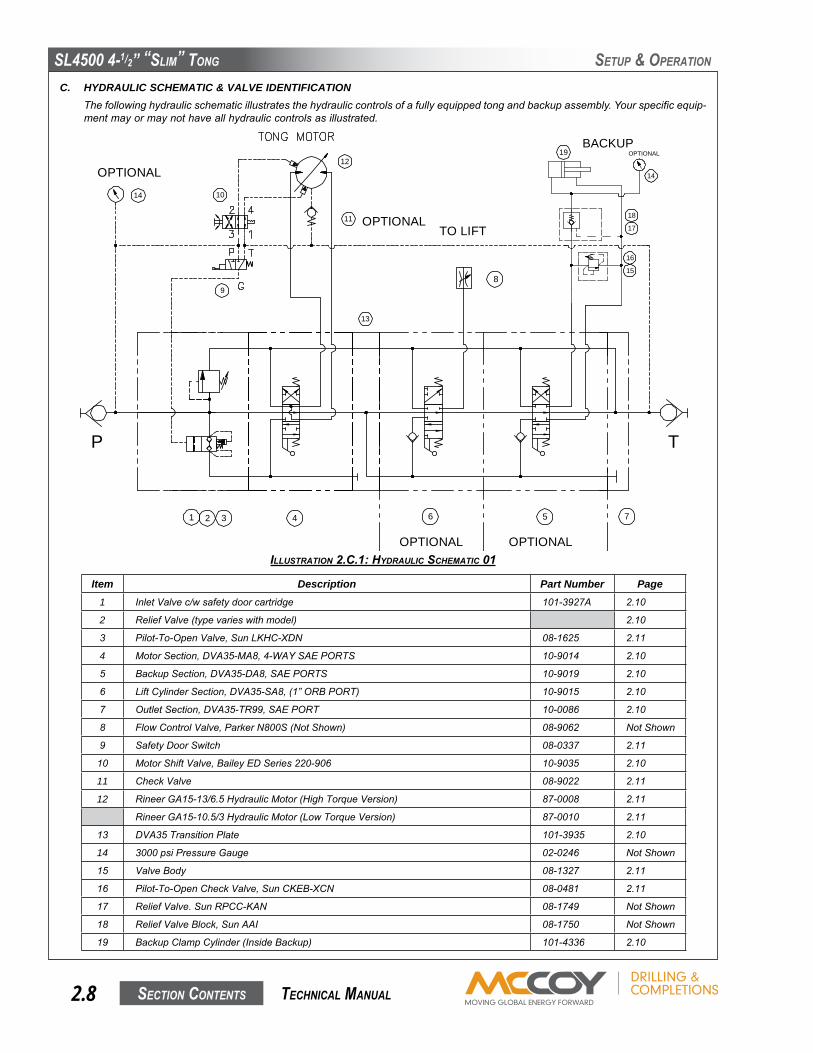
C. HYDRAULIC SCHEMATIC & VALVE IDENTIFICATIONThefollowinghydraulicschematicillustratesthehydrauliccontrolsofafullyequippedtongandbackupassembly.Yourspecificequip-mentmayormaynothaveallhydrauliccontrolsasillustrated.
11
12
10
9
14
1 2 3 4
T
6
8
TO LIFT
OPTIONAL
7
P
13
OPTIONAL
OPTIONAL
5
OPTIONAL
BACKUPOPTIONAL
14
16
15
18
17
19
Item Description Part Number Page1 InletValvec/wsafetydoorcartridge 101-3927A 2.10
2 ReliefValve(typevarieswithmodel) 2.10
3 Pilot-To-OpenValve,SunLKHC-XDN 08-1625 2.11
4 MotorSection,DVA35-MA8,4-WAYSAEPORTS 10-9014 2.10
5 BackupSection,DVA35-DA8,SAEPORTS 10-9019 2.10
6 LiftCylinderSection,DVA35-SA8,(1”ORBPORT) 10-9015 2.10
7 OutletSection,DVA35-TR99,SAEPORT 10-0086 2.10
8 FlowControlValve,ParkerN800S(NotShown) 08-9062 NotShown
9 SafetyDoorSwitch 08-0337 2.11
10 MotorShiftValve,BaileyEDSeries220-906 10-9035 2.10
11 CheckValve 08-9022 2.11
12 RineerGA15-13/6.5HydraulicMotor(HighTorqueVersion) 87-0008 2.11
RineerGA15-10.5/3HydraulicMotor(LowTorqueVersion) 87-0010 2.11
13 DVA35TransitionPlate 101-3935 2.10
14 3000psiPressureGauge 02-0246 NotShown
15 ValveBody 08-1327 2.11
16 Pilot-To-OpenCheckValve,SunCKEB-XCN 08-0481 2.11
17 ReliefValve.SunRPCC-KAN 08-1749 NotShown
18 ReliefValveBlock,SunAAI 08-1750 NotShown
19 BackupClampCylinder(InsideBackup) 101-4336 2.10
SeTuP & oPeRaTion
IllustratIon 2.c.1: hyDraulIc schematIc 01

SL4500 4-1/2” “SLim” Tong
SecTion conTenTS 2.9 TechnicaL manuaL
SeTuP & oPeRaTion
IllustratIon 2.c.2: hyDraulIc component IDentIfIcatIon 01
IllustratIon 2.c.3: hyDraulIc component IDentIfIcatIon 02
1
2
10
4
13
6
5
7
15
16
17
SL4500 4-1/2” “SLim” Tong
SecTion conTenTS2.10 TechnicaL manuaL
SeTuP & oPeRaTion
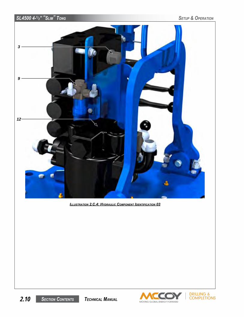
IllustratIon 2.c.4: hyDraulIc component IDentIfIcatIon 03
3
9
12

SL4500 4-1/2” “SLim” Tong
SecTion conTenTS 2.11 TechnicaL manuaL
SeTuP & oPeRaTion
D. HYDRAULIC CONNECTIONSApairofhydrauliclines-a1”supplylineanda1-1/4”returnline-connectthetongtothepowerunit(seeillustrationbelow).Ancillarydevices(hydraulicmotors,hydrauliccylinders,etc.)areconnectedthroughthevalveblock.
Performanyhydraulicconnectionwhenthepowerunitisnotrunning,orwhenthehydraulicpumpisdisengaged.Thepossibilityoferrorininter-changingthehighpressuresupplyhoseandthelowpressurereturnhosehasbeeneliminated,becausethesupplysidecouplingissmallerthanthereturnside.
THE INLET & OUTLET HYDRAULIC HOSES ANTI-WHIPLASH LANYARDS MUST BE ATTACHED TO THE TONG WITH ANTI-WHIPLASH LANYARDS
Thesehosecouplingsareself-sealing,andcareshouldbetakentoensurecompleteengagementtopreventpartialclosureofthecheckvalveinthecoupling.Ensurethatthenut(female)sideiscompletelymadeupontothemaleconnector-thereisalineonthemalefittingthatindicatescompletemake-up.Snugthefemalefittingrightuptotheline.
IllustratIon 2.D.1: hyDraulIc connectIons 01
IllustratIon 2.D.2: hyDraulIc connectIons 02
Make up female fitting to Marked point on male fitting
1” HydraulicInlet
1-1/4” HydraulicOutlet
SL4500 4-1/2” “SLim” Tong
SecTion conTenTS2.12 TechnicaL manuaL
Description Part Number Description Part Number
1.9”JawDieKit SL4500-JDK-1900 1.9”WrapAroundJawDieKit SL4500-WJDK-1900
2.063”JawDieKit SL4500-JDK-2063 2-3/8”WrapAroundJawDieKit SL4500-WJDK-2375
2-3/8”JawDieKit SL4500-JDK-2375 2-7/8”WrapAroundJawDieKit SL4500-WJDK-2875
2-7/8”JawDieKit SL4500-JDK-2875 3”WrapAroundJawDieKit SL4500-WJDK-3000
3”JawDieKit SL4500-JDK-3000 3.1875”WrapAroundJawDieKit SL4500-WJDK-3187
3.068”JawDieKit SL4500-JDK-3068 3-1/2”WrapAroundJawDieKit SL4500-WJDK-3500
3-1/2”JawDieKit SL4500-JDK-3500 3-5/8”WrapAroundJawDieKit SL4500-WJDK-3625
3-5/8”JawDieKit SL4500-JDK-3625 4”WrapAroundJawDieKit SL4500-WJDK-4000
3.668”JawDieKit SL4500-JDK-3668 4-1/2”WrapAroundJawDieKit SL4500-WJDK-4500
4”JawDieKit SL4500-JDK-4000 5”WrapAroundJawDieKit SL4500-WJDK-5000
4-1/2”JawDieKit SL4500-JDK-4500
Alljawdiekitsexcept“Wraparound”useflatdieP/N12-1003MOD
ContactFarrSalesfor“Wraparound”dies.
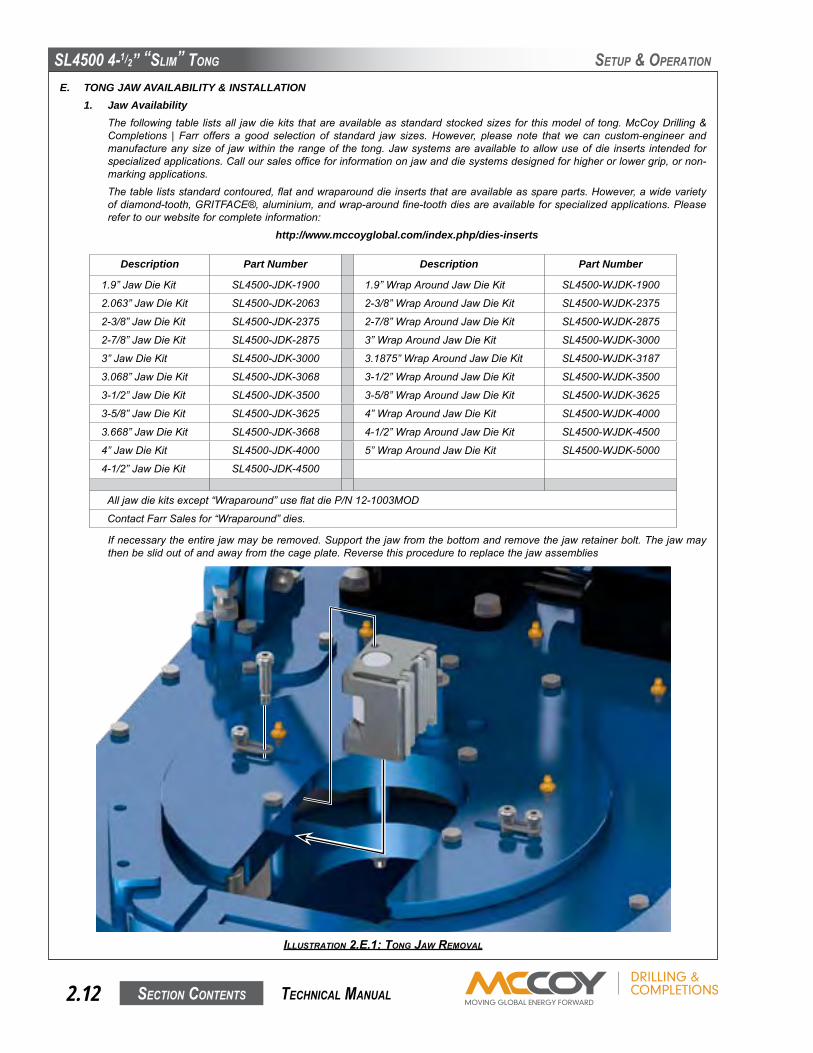
Ifnecessarytheentirejawmayberemoved.Supportthejawfromthebottomandremovethejawretainerbolt.Thejawmaythenbeslidoutofandawayfromthecageplate.Reversethisproceduretoreplacethejawassemblies
SeTuP & oPeRaTion
IllustratIon 2.e.1: tong Jaw removal
E. TONG JAW AVAILABILITY & INSTALLATION1. Jaw Availability
Thefollowingtable listsall jawdiekits thatareavailableasstandardstockedsizes for thismodelof tong.McCoyDrilling&Completions | Farr offers a good selection of standard jaw sizes.However, please note thatwe can custom-engineer andmanufactureanysizeof jawwithin therangeof the tong.Jawsystemsareavailable toallowuseofdie inserts intendedforspecializedapplications.Calloursalesofficeforinformationonjawanddiesystemsdesignedforhigherorlowergrip,ornon-markingapplications.
Thetablelistsstandardcontoured,flatandwraparounddieinsertsthatareavailableasspareparts.However,awidevarietyofdiamond-tooth,GRITFACE®,aluminium,andwrap-aroundfine-toothdiesareavailableforspecializedapplications.Pleaserefertoourwebsiteforcompleteinformation:
http://www.mccoyglobal.com/index.php/dies-inserts

SL4500 4-1/2” “SLim” Tong
SecTion conTenTS 2.13 TechnicaL manuaL
SeTuP & oPeRaTion
2. Backup JawsThejawdiekitsusedintheFarrbackupareidenticaltothoseusedinthe“slim”tong(seepreviouspage).Followthesameremovalandinstallationinstructionsasforthetongjawdiekits.
3. Tong HandlesTonghandlesmaybesuppliedasanaccessorywiththistong.Theymayberemovedforoperationalneedsandrequirements.
F. TONG RIG-UP & LEVELING1. Suspension & Restraint
Suspendthetongandbackupfromalocationasneartothecentreofthedrillrotaryaspossible,andfromalocationhighenoughonthemasttoensureeasyhandling.Thelowerthepointfromwhichthetongissuspended,themoreeffortwillberequiredtomovethetongtoandfromtheconnectionpoint.
Thesuspensionlinemaybeextendedoverapulleyandbalancedbyacounterweightequaltotheweightofthetongandbackup,orsimplytiedoffinthederricktoformadeadline.WhenusingadeadlinearrangementitisnecessarytouseaFARRspringhangerassembly(seespecificationpageforrecommendedspringhanger).Thisspringhangercompensatesforthedownwardmovementofthecasingasthethreadismade-up,andimpartsadditionalforcetothesuspensioncable:
● a“singlespring”hangertypicallyapplies420lbs.(191kg.)tothesuspensionlineforeveryinchofthreadmadeup● a“doublespring”hangertypicallyapplies840lbs.(382kg.)tothesuspensionlineforeveryinchofthreadmadeup
Ifyoudonotknowwhichspecificspringhanger is inuse,checkthespecificationpageinthismanual for informationontherecommendedspringhanger for thisapplication.McCoyDrilling&CompletionswillnotguaranteeorspecifyspringhangersotherthanwhathasbeensuppliedbyMcCoy.
Manyapplicationsusealiftcylinderforadjustingtheheightofthetong.Ensuretheweightoftheliftcylinderisknownifithasnotbeenincludedinthetotalweightofthetong.
Toreleasediesfromajawassembly,removetheretainingboltsandslidediesout.Repeatthisprocedureinreversetoinstallnewdies.
IllustratIon 2.e.2: tong Jaw DIe replacement
Wraparound Style Jaw
Standard Style Jaw
SL4500 4-1/2” “SLim” Tong
SecTion conTenTS2.14 TechnicaL manuaL
SeTuP & oPeRaTion
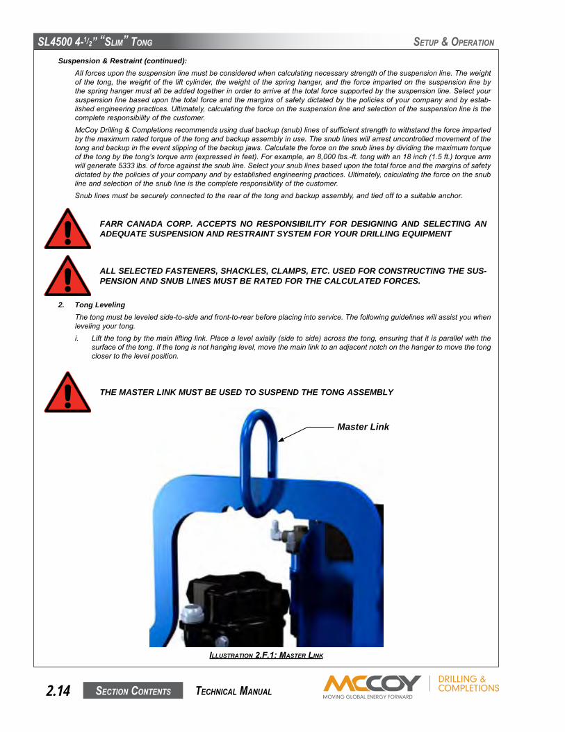
Suspension & Restraint (continued):Allforcesuponthesuspensionlinemustbeconsideredwhencalculatingnecessarystrengthofthesuspensionline.Theweightof the tong, theweightof the liftcylinder, theweightof thespringhanger,andthe force impartedonthesuspension linebythespringhangermustallbeaddedtogetherinordertoarriveatthetotalforcesupportedbythesuspensionline.Selectyoursuspensionlinebaseduponthetotalforceandthemarginsofsafetydictatedbythepoliciesofyourcompanyandbyestab-lishedengineeringpractices.Ultimately,calculatingtheforceonthesuspensionlineandselectionofthesuspensionlineisthecompleteresponsibilityofthecustomer.
McCoyDrilling&Completionsrecommendsusingdualbackup(snub)linesofsufficientstrengthtowithstandtheforceimpartedbythemaximumratedtorqueofthetongandbackupassemblyinuse.Thesnublineswillarrestuncontrolledmovementofthetongandbackupintheeventslippingofthebackupjaws.Calculatetheforceonthesnublinesbydividingthemaximumtorqueofthetongbythetong’storquearm(expressedinfeet).Forexample,an8,000lbs.-ft.tongwithan18inch(1.5ft.)torquearmwillgenerate5333lbs.offorceagainstthesnubline.Selectyoursnublinesbaseduponthetotalforceandthemarginsofsafetydictatedbythepoliciesofyourcompanyandbyestablishedengineeringpractices.Ultimately,calculatingtheforceonthesnublineandselectionofthesnublineisthecompleteresponsibilityofthecustomer.
Snublinesmustbesecurelyconnectedtotherearofthetongandbackupassembly,andtiedofftoasuitableanchor.
THE MASTER LINK MUST BE USED TO SUSPEND THE TONG ASSEMBLY
IllustratIon 2.f.1: master lInk
2. Tong LevelingThetongmustbeleveledside-to-sideandfront-to-rearbeforeplacingintoservice.Thefollowingguidelineswillassistyouwhenlevelingyourtong.i. Liftthetongbythemainliftinglink.Placealevelaxially(sidetoside)acrossthetong,ensuringthatitisparallelwiththe
surfaceofthetong.Ifthetongisnothanginglevel,movethemainlinktoanadjacentnotchonthehangertomovethetongclosertothelevelposition.
FARR CANADA CORP. ACCEPTS NO RESPONSIBILITY FOR DESIGNING AND SELECTING AN ADEQUATE SUSPENSION AND RESTRAINT SYSTEM FOR YOUR DRILLING EQUIPMENT
ALL SELECTED FASTENERS, SHACKLES, CLAMPS, ETC. USED FOR CONSTRUCTING THE SUS-PENSION AND SNUB LINES MUST BE RATED FOR THE CALCULATED FORCES.
Master Link
SL4500 4-1/2” “SLim” Tong
SecTion conTenTS 2.15 TechnicaL manuaL
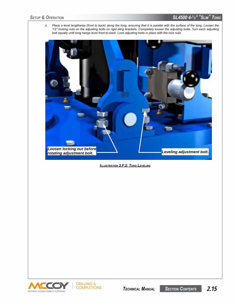
ii. Placealevellengthwise(fronttoback)alongthetong,ensuringthatitisparallelwiththesurfaceofthetong.Loosenthe1/2”lockingnutsontheadjustingboltsonrigidslingbrackets.Completelyloosentheadjustingbolts.Turneachadjustingboltequallyuntiltonghangslevelfront-to-back.Lockadjustingboltsinplacewiththelocknuts.
SeTuP & oPeRaTion
IllustratIon 2.f.2: tong levelIng
Loosen locking nut before rotating adjustment bolt. Leveling adjustment bolt.
SL4500 4-1/2” “SLim” Tong
SecTion conTenTS2.16 TechnicaL manuaL
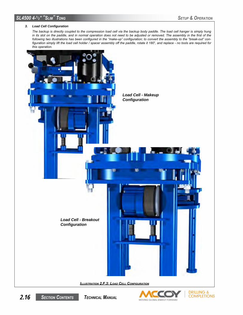
3. Load Cell ConfigurationThebackupisdirectlycoupledtothecompressionloadcellviathebackupbodypaddle.Theloadcellhangerissimplyhungin itsslotonthepaddle,and innormaloperationdoesnotneedtobeadjustedorremoved.Theassembly in thefirstof thefollowingtwoillustrationshasbeenconfiguredinthe“make-up”configuration;toconverttheassemblytothe“break-out”con-figurationsimplylifttheloadcellholder/spacerassemblyoffthepaddle,rotateit180o,andreplace-notoolsarerequiredforthisoperation.
SeTuP & oPeRaTion
IllustratIon 2.f.3: loaD cell confIguratIon
Load Cell - Makeup Configuration
Load Cell - Breakout Configuration

SL4500 4-1/2” “SLim” Tong
SecTion conTenTS 2.17 TechnicaL manuaL
SeTuP & oPeRaTion
McCoyDrilling&Completionsrecommendsthatthefollowingpre-operatingtestsbeperformedafterreceiptfromthefactoryorafterextendedstorage,priortoreleasingthetongtooperations:• Performacompleteinspectionofallfastenerstoensurenonehaveloosenedduringtransport.• Connectthetongtothepowerunit,andapplyfullhydraulicpressure.Inspectandcorrectanyleaks.• Operatethetongatfullspeedandinhighgearforadurationofone-halfhour.Hotbearingcapsmayindicateimpendingbear-ingfailure.
• Switchtolowgearandoperateforanadditionalone-halfhouratfullspeed.• Runthebackupthroughseveralclamp/un-clampsequencestoensurefunctionality.• Inspectall componentsandhydraulic fittings forpossibledefects followingcompletionof the tests.AllFARRTongshavebeenthoroughlytestedatthefactorypriortoshipping,butshippingdamagemustbeidentifiedbeforerunningthetonginanoperationalenvironment.
• Carefullyinspectthesafetydoorcomponents,andtesttoensurethatthesafetydeviceoneachdoorisoperatingcorrectlybeforereleasingthetongtotheoperatingenvironment.
YOUR EQUIPMENT HAS BEEN THOROUGHLY TESTED AND INSPECTED AT THE FACTORY. HOWEVER, WE ADVISE INSPECTION AND TESTING OF YOUR NEW TONG AFTER TAKING POSSESSION IN ORDER TO ELIMINATE THE POSSIBILITY OF SHIPPING DAMAGE.
G. TONG OPERATION1. Operator Training
Manycompaniessetqualificationstandardsthatmustbemetbeforeequipmentismaybeoperatedwithoutsupervision.McCoyDrilling&Completionsrecommendsoperatortraining,whichtypicallyconsistsofoperationoftheequipmentunderthesupervi-sionofatrainedequipmentoperatoruntilasatisfactorylevelofcompetenceisachieved.Typicaloperatortrainingshouldinclude:• Introductiontoandgeneraldescriptionofequipment• Technicalspecificationsandperformancedata• Operatinginstructions• Controlsystemsandinterlocks• Operatinghazards• Checksandinspections
2. Initial Start-up and Break-in Procedure
Ensureadequatelubeoilandhydraulicoillevelsbeforestartingengine.Usestartupproceduresasrecommendedbythepowerunitengineoperator’smanual.OpentheBypassValveonthehydraulicsystem,andinspectallpressureandreturnlinehoseconnectionstoensurecorrectandsecureinstallation.
TONG DOOR MUST BE CLOSED AND SECURELY LATCHED BEFORE THE POWER UNIT IS STARTED IN ORDER TO ASSURE THE SAFETY OF OPERATING PERSONNEL
IMPROPERLY SECURED HYDRAULIC CONNECTIONS WILL INTERRUPT HYDRAULIC FLUID FLOW, AND COULD RESULT IN THE FOLLOWING FAILURES:
● Arestrictioninthepressuresupplyhosewillresultinhighpressurewithinthepowerunithydraulicsystem,whichwillactivatethehydraulicgovernorandincreasetheenginespeedtoashighasmaximumRPM.
● Arestrictioninthereturnlinewillresultinhighpressurewithinthepowerunitandthetonghydraulicsystem,causingenginespeedsashighasmaximumRPM,andpossiblefailureofthemotorseal.
Followinginspectionofthehoses,starttheengineandallowittoidleuntilwarm.Allowhydraulicfluidtocirculateforapproxi-mately10minutes,thenslowlyclosetheBypassValvetoallowhydraulicfluidtocirculatethroughthehosesandtothetong(circulatingpressureshouldnotexceed200psi).Placethetonggearshifterinlowgearandrotatethetongslowlyforwardandthenreversewiththethrottlevalvecontrollever.Oncethishasbeendoneandthepropersizejawshavebeeninstalled,thetongisthenreadytorunpipe.
SL4500 4-1/2” “SLim” Tong
SecTion conTenTS2.18 TechnicaL manuaL
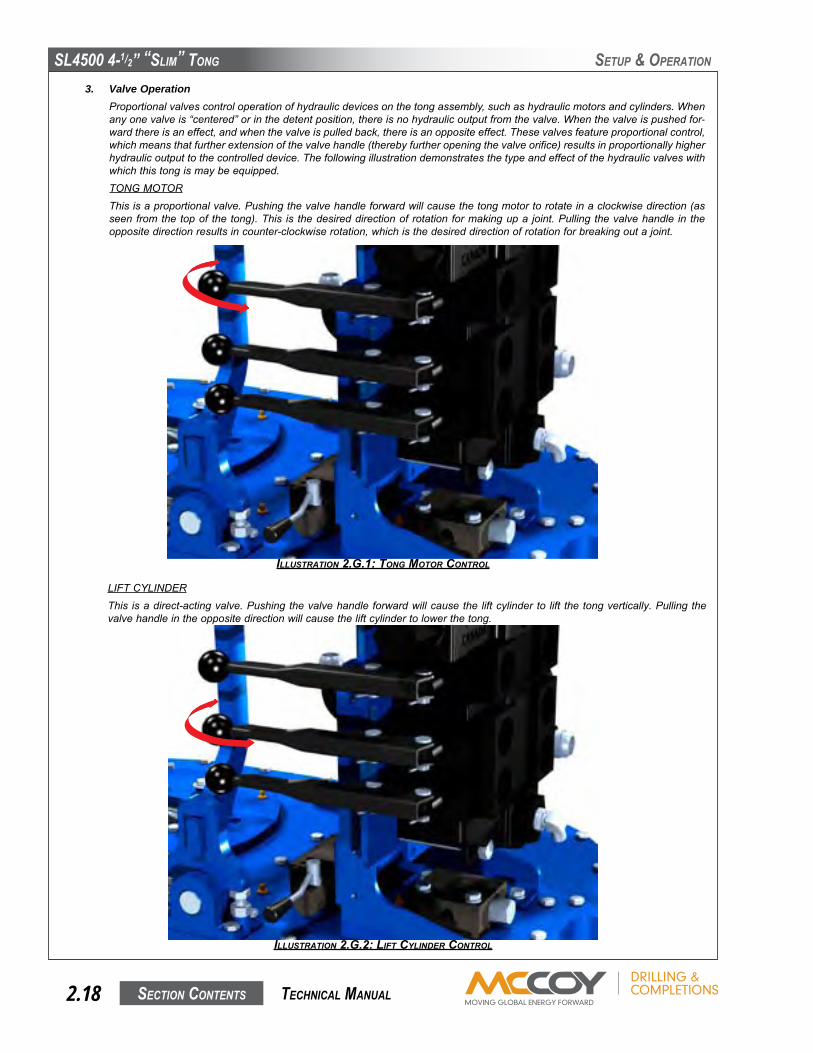
3. Valve OperationProportionalvalvescontroloperationofhydraulicdevicesonthetongassembly,suchashydraulicmotorsandcylinders.Whenanyonevalveis“centered”orinthedetentposition,thereisnohydraulicoutputfromthevalve.Whenthevalveispushedfor-wardthereisaneffect,andwhenthevalveispulledback,thereisanoppositeeffect.Thesevalvesfeatureproportionalcontrol,whichmeansthatfurtherextensionofthevalvehandle(therebyfurtheropeningthevalveorifice)resultsinproportionallyhigherhydraulicoutputtothecontrolleddevice.Thefollowingillustrationdemonstratesthetypeandeffectofthehydraulicvalveswithwhichthistongismaybeequipped.
TONGMOTOR
Thisisaproportionalvalve.Pushingthevalvehandleforwardwillcausethetongmotortorotateinaclockwisedirection(asseenfromthetopof thetong).This is thedesireddirectionofrotationformakingupa joint.Pullingthevalvehandle in theoppositedirectionresultsincounter-clockwiserotation,whichisthedesireddirectionofrotationforbreakingoutajoint.
LIFTCYLINDER
This isadirect-actingvalve.Pushingthevalvehandleforwardwillcausetheliftcylinderto lift thetongvertically.Pullingthevalvehandleintheoppositedirectionwillcausetheliftcylindertolowerthetong.
SeTuP & oPeRaTion
IllustratIon 2.g.1: tong motor control
IllustratIon 2.g.2: lIft cylInDer control

SL4500 4-1/2” “SLim” Tong
SecTion conTenTS 2.19 TechnicaL manuaL
BACKUP
Thisisatwo-waydirectactingvalve,withoutproportionalcontrol.Pushingthevalvehandleforwardwillcausethe backuptoengage.Pullingbackward,towardstheoperator,reversestheoperation.
TONGSPEED
Themotorspeedvalveofferssafeandsmoothadjustmentofthetongspeedwithouttheneedtomanipulategearsinageartrain.Simplyrotatethespeedvalvetochangethespeedofthemotor.Thesimplicityofthissystemisparticularlyusefulwhenmakinguporbreakingoutajoint.
SeTuP & oPeRaTion
IllustratIon 2.g.3: Backup clamp control
IllustratIon 2.g.4: motor speeD control

SL4500 4-1/2” “SLim” Tong
SecTion conTenTS2.20 TechnicaL manuaL
4. GENERALCOMMENTSa) Positionrotarygearincontactwithbothidlergearswhenbreakingoutjointsorcollarswherehightorquesarerequired.b) Whenmaking-upintegral(shouldered)joints,itisessentialtomakeupthelastturnofthethreadsinlowgear.Thisreduces
thetendencyofaninstantstoporasuddenincreaseintorque,whichinducesextremelyhighstressesonthegeartrain.c) DONOTemploy the “snap break”method of breaking-out jointswhen pulling a string.By definition, the “snap break”
methodisaprocedureusedbysomeoperatorstobreakoutconnections,accomplishedbyleavingslackinthe“jaw-pipe”engagement,andthenquicklypullingthethrottlevalvecontrolleverallowingthetongtosnapintoitsloadedorhightorquecondition.Althoughthismethodisveryeffectiveinbreakingoutjoints,theextremelyhighstressplacedonthegeartrainfrequentlycausesgearbreakage.
H. EXTREME COLD WEATHER OPERATION PROCEDURES1) Consultthepowerunitengineoperator’smanualforallcoldweatheroperatingproceduresandprecautions.2) Selectgearandbearinglubricantsthatarecompatiblewithexpectedclimaticconditions.3) Selecthydraulicfluidthatiscompatiblewithexpectedclimaticconditions.4) Allowhydraulicfluidtocirculateforapproximately20minutesafterstartingthepowerunit,priortoactivatingthebypassvalve
toallowfluidtocirculatetotong.Ifthepowerunitisequippedwithanoiltemperaturegauge,ensurethatthefluidhasreachedoperatingtemperatureasspecifiedbyhydraulicfluiddatasheet.
5) Allowforadequatedryingofmoisture(priortolubricating)whencleaningtongpartsincoldweather.
SeTuP & oPeRaTion
THE “SNAP-BREAK” METHOD IS HAZARDOUS TO RIG PERSONNEL

SL4500 4-1/2” “SLim” Tong
SecTion conTenTS 2.21 TechnicaL manuaL
SeTuP & oPeRaTion
I. MAKING AND BREAKING CONNECTIONS
SetupandprepareyourequipmentforoperationasperSection2oftheSL-4500TechnicalManual.Refertothefollowingsections:• 2.D-HydraulicConnections• 2.E-Tong&BackupJawInstallation• 2.F.1-TongRig-upandLeveling,Suspension• 2.F.2-TongRig-upandLeveling,Leveling
• 2.F.3-TongRig-upandLeveling,LoadCellConfiguration
Yourtongandbackupassemblyshouldbeproperlysuspended,connectedtoahydraulicpowersource,andreadytomakeorbreakconnectionsatthispoint.
THIS PROCEDURE ASSUMES THE USER HAS PROPERLY SET UP AND PREPARED THE EQUIP-MENT FOR OPERATION AS PER SECTION 2 OF THE TECHNICAL MANUAL
THE MASTER LINK MUST BE USED TO SUSPEND THE TONG ASSEMBLY
b) Ensure thebackingpin is in the “makeup”position.From the frontof the tong, thebackingpincorrectlyconfigured formakeupwillbeinthe10o’clockposition.Ifitisnot,simplyliftupandplaceinthecorrectposition(seeIllustration2.I.2nextpage).Thecageplateopeningmustbealignedwiththedooropeningwhensettingthebackingpinposition.
1. Making Up A Connectiona) Ensurehydraulicpowersupplytothetongandbackupisenergized.Themaster linkontherigidslingmustbeusedto
suspendthetong.Donotsuspendthetongdirectlyfromtherigidsling.
IllustratIon 2.I.1: tong suspensIon - master lInk

SL4500 4-1/2” “SLim” Tong
SecTion conTenTS2.22 TechnicaL manuaL
c) Ensuretheloadcellisproperlyconfiguredformakingupconnections.SeeSection2.F.3oftheSL-4500TechnicalManualforcorrectlyconfiguringyourequipment.
d) McCoyDrilling&Completionsrecommendsthatbackuppressurebepre-setforthesizeoftubingbeforestartingthejob(notubingisrequiredforthisprocedure):• Backupclampingpressureisonlydisplayedwhenthebackupjawsareclosedinthe“clamp”position.Closethebackupjawsusingthebackupcontrolhandle.
Making A Connection (continued):
IllustratIon 2.I.2: settIng BackIng pIn to “make-up”
IllustratIon 2.I.3: Backup control
SeTuP & oPeRaTion

SL4500 4-1/2” “SLim” Tong
SecTion conTenTS 2.23 TechnicaL manuaL
Making A Connection (continued):
d) Settingbackuppressure(continued)• Observethebackuppressureasindicatedonthe“CLAMP”pressuregauge
• Hydraulicpressureontheclampcylindersmustberelievedbeforetheclampingpressurecanbeadjusted.Relievepres-surebypullingbackonthebackupcontrolhandleenoughtoactuatetherelief,butnotenoughtoretractthecylinder.
• Usethebackuppressurecontrolknobtoadjustthepressure.Turningtheknobclockwiseincreasesclampingpressure,andturningthecontrolknobcounter-clockwisedecreasesclampingpressure.
Turntheknobinsmallincrementsi.e.1/4turnatatime,andcheckclampingpressureaftereverypressureadjustment.Ensurethepressureontheclampcylindersisrelievedbeforere-adjustingpressure.
IllustratIon 2.I.4: clamp pressure gauge on gauge panel
IllustratIon 2.I.5: Backup pressure control valve
SeTuP & oPeRaTion
SL4500 4-1/2” “SLim” Tong
SecTion conTenTS2.24 TechnicaL manuaL
SeTuP & oPeRaTion
Making A Connection (continued):
d) Settingbackuppressure(continued)• Ifpressuredatafrompreviousjobsisunavailable,McCoyrecommendssettingtheinitialbackuppressureto1900PSIandincreasethepressureincrementallyifrequired.Ifpressuredataisavailable,setthefinalbackuppressuretothepres-surerequiredforthejob.Duetoawidevarietyoftubingwallthicknessesitisimpossibletorecommendoptimumbackuppressuresettingsfromthefactoryforeachsizeoftubing.
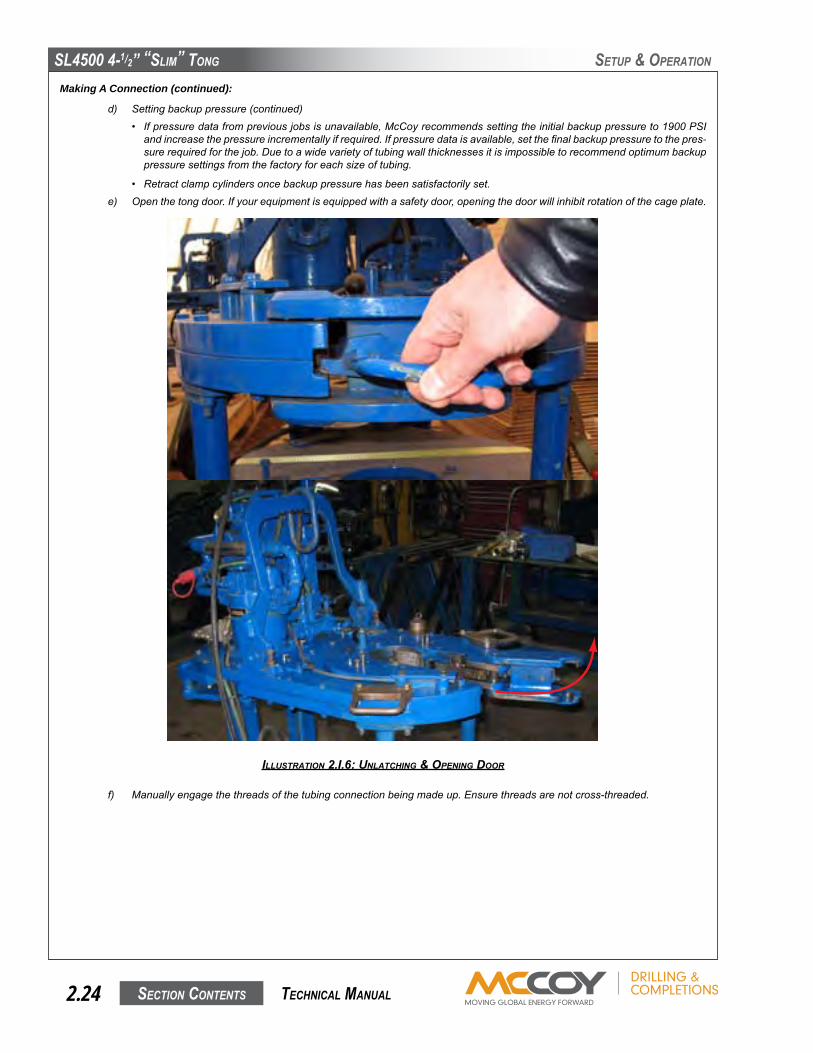
• Retractclampcylindersoncebackuppressurehasbeensatisfactorilyset.e) Openthetongdoor.Ifyourequipmentisequippedwithasafetydoor,openingthedoorwillinhibitrotationofthecageplate.
f) Manuallyengagethethreadsofthetubingconnectionbeingmadeup.Ensurethreadsarenotcross-threaded.
IllustratIon 2.I.6: unlatchIng & openIng Door
SL4500 4-1/2” “SLim” Tong
SecTion conTenTS 2.25 TechnicaL manuaL
SeTuP & oPeRaTion
Making A Connection (continued):
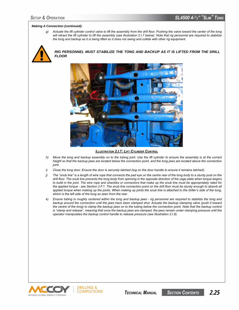
g) Actuatetheliftcylindercontrolvalvetolifttheassemblyfromthedrillfloor.Pushingthevalvetowardthecenterofthetongwillretracttheliftcylindertolifttheassembly(seeillustration2.I.7below).Notethatrigpersonnelarerequiredtostabilizethetongandbackupasitisbeingliftedsoitdoesnotswingandcollidewithotherrigequipment.
RIG PERSONNEL MUST STABILIZE THE TONG AND BACKUP AS IT IS LIFTED FROM THE DRILL FLOOR
h) Movethetongandbackupassemblyontothetubingjoint.Usetheliftcylindertoensuretheassemblyisatthecorrectheightsothatthebackupjawsarelocatedbelowtheconnectionpoint,andthetongjawsarelocatedabovetheconnectionjoint.
i) Closethetongdoor.Ensurethedoorissecurelylatched(tugonthedoorhandletoensureitremainslatched).j) The“snubline”isalengthofwireropethatconnectsthepadeyeonthecentrerearofthetongbodytoasturdypostonthe
drillfloor.Thesnublinepreventsthetongbodyfromspinningintheoppositedirectionofthecageplatewhentorquebeginstobuildinthejoint.Thewireropeandshacklesorconnectorsthatmakeupthesnublinemustbeappropriatelyratedfortheappliedtorque-seeSection2.F.1.Thesnublineconnectionpointonthedrillfloormustbesturdyenoughtoabsorballappliedtorquewhenmakingupthejoints.Whenmakingupjointsthesnublineisattachedtothedriller’ssideofthetong,whichistheleftsideofthetongasseenfromtherear.
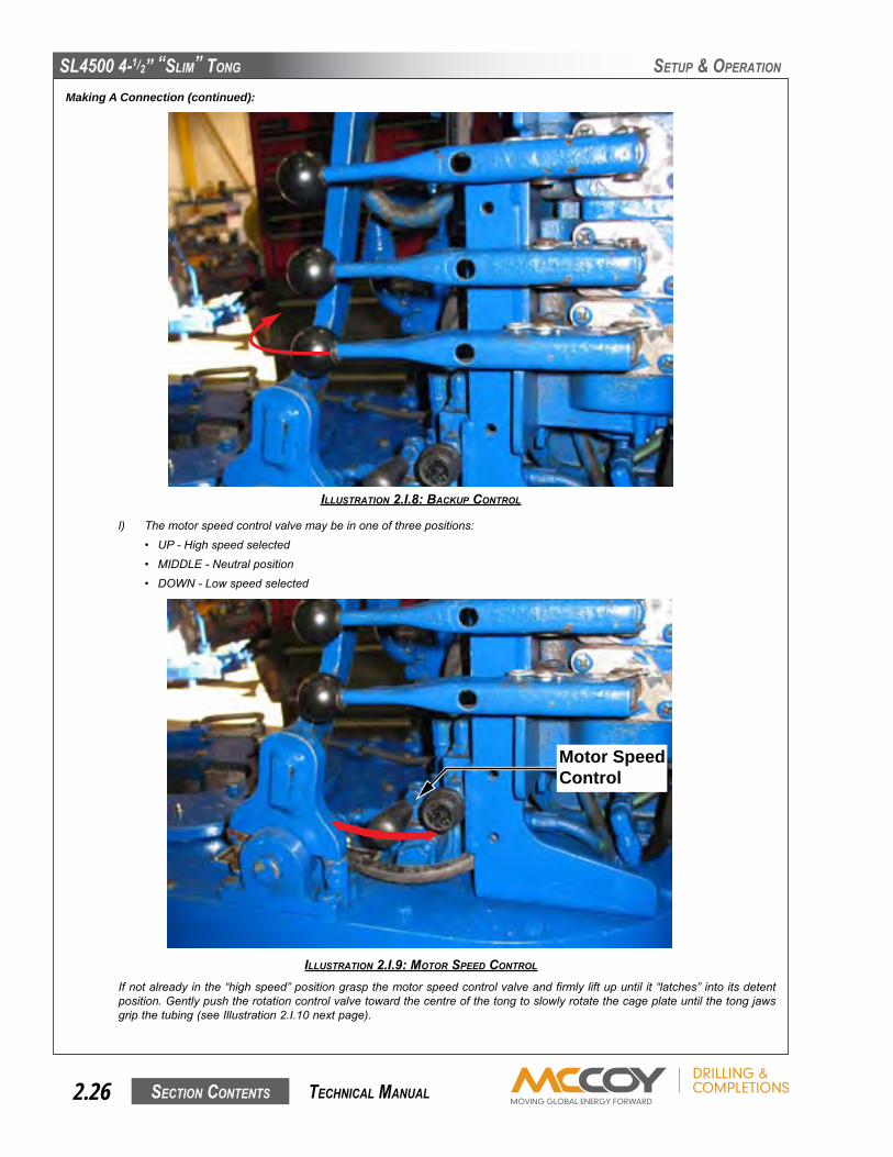
k) Ensuretubingisroughlycenteredwithinthetongandbackupjaws-rigpersonnelarerequiredtostabilizethetongandbackuparoundtheconnectionuntilthejawshavebeenclampedshut.Actuatethebackupclampingvalve(pushittowardthecentreofthetong)toclampthebackupjawsontothetubingbelowtheconnectionpoint.Notethatthebackupcontrolis“clampandrelease”,meaningthatoncethebackupjawsareclamped,thejawsremainunderclampingpressureuntiltheoperatormanipulatesthebackupcontrolhandletoreleasepressure(seeIllustration2.I.8).
IllustratIon 2.I.7: lIft cylInDer control
SL4500 4-1/2” “SLim” Tong
SecTion conTenTS2.26 TechnicaL manuaL
SeTuP & oPeRaTion
Making A Connection (continued):
l) Themotorspeedcontrolvalvemaybeinoneofthreepositions:• UP-Highspeedselected• MIDDLE-Neutralposition• DOWN-Lowspeedselected
Ifnotalreadyinthe“highspeed”positiongraspthemotorspeedcontrolvalveandfirmlyliftupuntilit“latches”intoitsdetentposition.Gentlypushtherotationcontrolvalvetowardthecentreofthetongtoslowlyrotatethecageplateuntilthetongjawsgripthetubing(seeIllustration2.I.10nextpage).
IllustratIon 2.I.8: Backup control
IllustratIon 2.I.9: motor speeD control
Motor SpeedControl
SL4500 4-1/2” “SLim” Tong
SecTion conTenTS 2.27 TechnicaL manuaL
SeTuP & oPeRaTion
Making A Connection (continued):
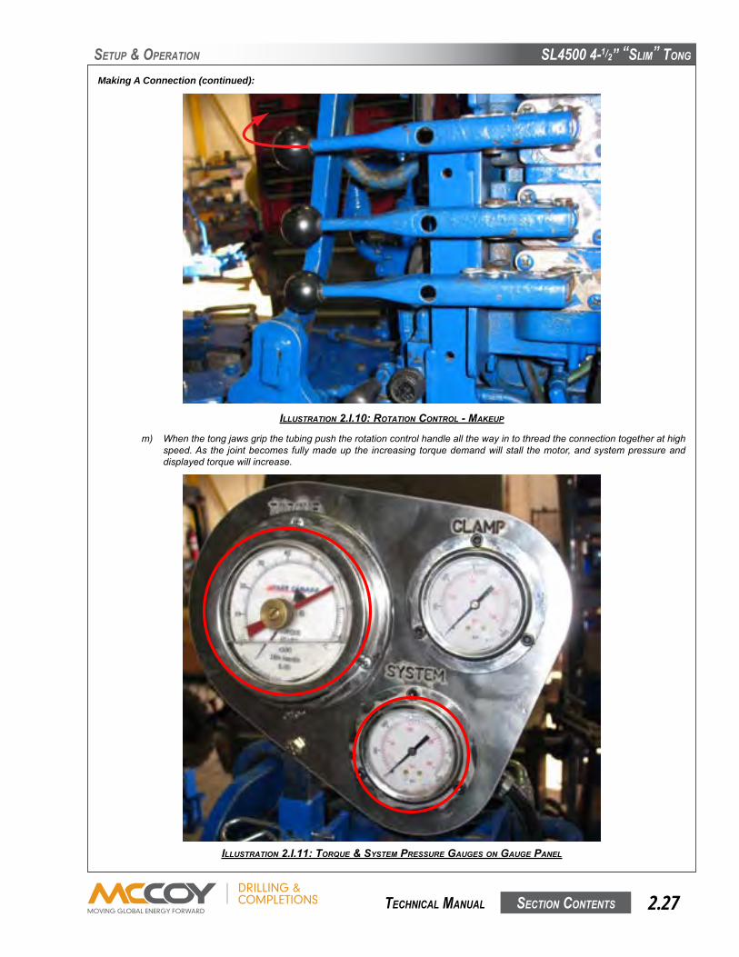
m) Whenthetongjawsgripthetubingpushtherotationcontrolhandleallthewayintothreadtheconnectiontogetherathighspeed.Asthe jointbecomesfullymadeupthe increasingtorquedemandwillstall themotor,andsystempressureanddisplayedtorquewillincrease.
IllustratIon 2.I.10: rotatIon control - makeup
IllustratIon 2.I.11: torque & system pressure gauges on gauge panel

SL4500 4-1/2” “SLim” Tong
SecTion conTenTS2.28 TechnicaL manuaL
SeTuP & oPeRaTion
o) Observethetubinginthebackupasthejointisapproachesthespecifiedmake-uptorque.Ifthetubingbeginstoslipinthebackup,increasethebackuppressurein50psiincrementsuntilthetubingstopsslipping.Makeuptorquemustbereachedwithoutanytubingrotationinthebackup.Whenthathasbeenachievedrecordthebackuppressureforfuturereference.Asyougainexperiencewithyourequipmentmakeupa“pressurevs.tubingsize”chartthatcanbereferredtowhenmakingfutureconnections,ensuringproperbackuppressuresettingswithoutriskingcrushedtubing.
p) Whenpropermakeuptorquehasbeenreachedreversetherotationcontrolvalvetoreleasethetongjawsfromthetubing.
Making A Connection (continued):
n) Whensystempressureandtorquebegintorise,switchtolowspeed:• Donotreleasetherotationcontrol• Graspthespeedcontrolknobandfirmlypushitdowntothelowspeedsetting.Motorspeeddecreasesby50percent,andavailabletorquedoubles.
IllustratIon 2.I.12: swItchIng motor speeD swItch to low speeD
IllustratIon 2.I.13: reversIng rotatIon to free tong Jaws

SL4500 4-1/2” “SLim” Tong
SecTion conTenTS 2.29 TechnicaL manuaL
SeTuP & oPeRaTion
Making A Connection (continued):
q) Whentongjawsarefreereleasethebackupjawsbypullingthebackupclampcontrolhandleawayfromthetongtowardtheoperator.
r) Unlatchandopenthetongdoortofreetheassemblyfromthetubing.Notethatrigpersonnelmayberequiredtostabilizetheequipmentasitcompletelyreleasesfromthetubing.Guidetheassemblyawayfromthestringandusetheliftcylindercontroltolowerittothedrillfloor.
s) Repeatsteps“e”through“r”untilthedesirednumberofconnectionsaremadeup.
IllustratIon 2.I.14: un-clampIng Backup Jaws
IllustratIon 2.I.15: lowerIng assemBly usIng lIft cylInDer control
SL4500 4-1/2” “SLim” Tong
SecTion conTenTS2.30 TechnicaL manuaL
SeTuP & oPeRaTion
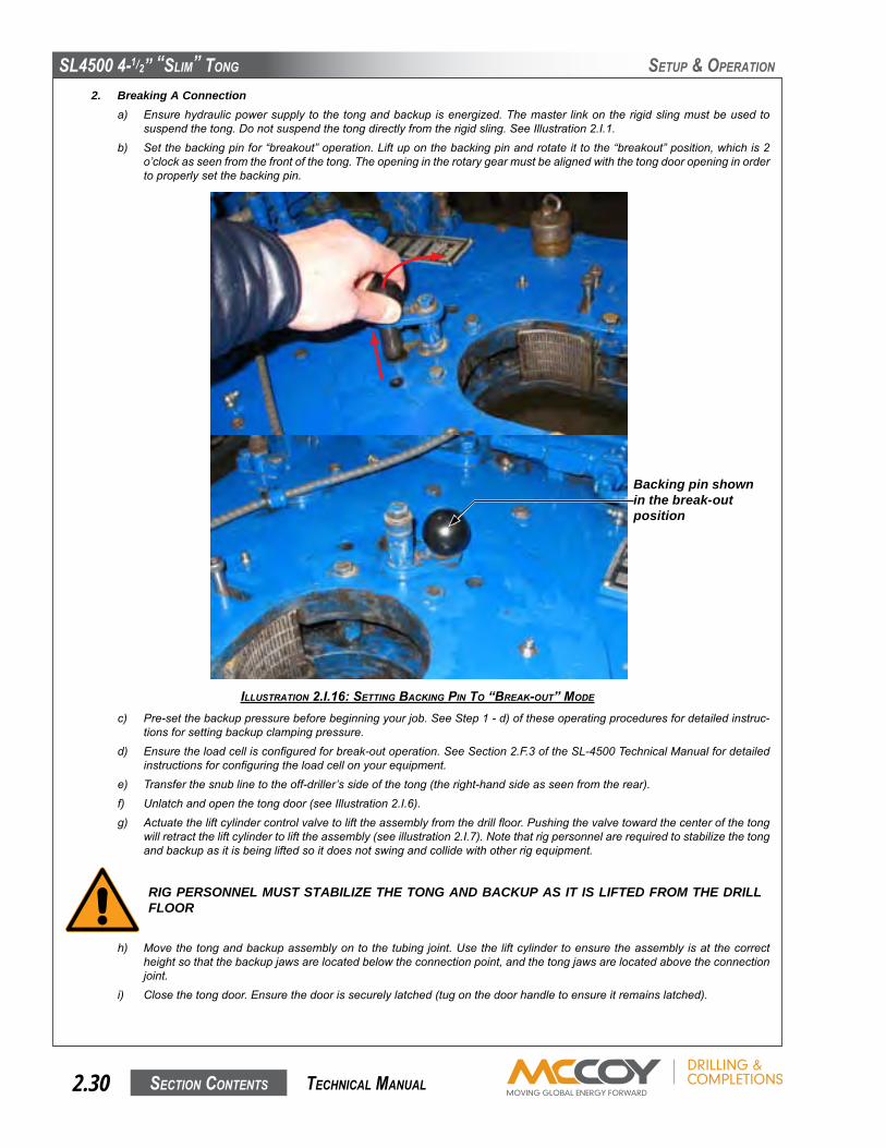
2. Breaking A Connectiona) Ensurehydraulicpowersupplytothetongandbackupisenergized.Themaster linkontherigidslingmustbeusedto
suspendthetong.Donotsuspendthetongdirectlyfromtherigidsling.SeeIllustration2.I.1.b) Setthebackingpinfor“breakout”operation.Liftuponthebackingpinandrotateittothe“breakout”position,whichis2
o’clockasseenfromthefrontofthetong.Theopeningintherotarygearmustbealignedwiththetongdooropeninginordertoproperlysetthebackingpin.
c) Pre-setthebackuppressurebeforebeginningyourjob.SeeStep1-d)oftheseoperatingproceduresfordetailedinstruc-tionsforsettingbackupclampingpressure.
d) Ensuretheloadcellisconfiguredforbreak-outoperation.SeeSection2.F.3oftheSL-4500TechnicalManualfordetailedinstructionsforconfiguringtheloadcellonyourequipment.
e) Transferthesnublinetotheoff-driller’ssideofthetong(theright-handsideasseenfromtherear).f) Unlatchandopenthetongdoor(seeIllustration2.I.6).g) Actuatetheliftcylindercontrolvalvetolifttheassemblyfromthedrillfloor.Pushingthevalvetowardthecenterofthetong
willretracttheliftcylindertolifttheassembly(seeillustration2.I.7).Notethatrigpersonnelarerequiredtostabilizethetongandbackupasitisbeingliftedsoitdoesnotswingandcollidewithotherrigequipment.
RIG PERSONNEL MUST STABILIZE THE TONG AND BACKUP AS IT IS LIFTED FROM THE DRILL FLOOR
IllustratIon 2.I.16: settIng BackIng pIn to “Break-out” moDe
h) Movethetongandbackupassemblyontothetubingjoint.Usetheliftcylindertoensuretheassemblyisatthecorrectheightsothatthebackupjawsarelocatedbelowtheconnectionpoint,andthetongjawsarelocatedabovetheconnectionjoint.
i) Closethetongdoor.Ensurethedoorissecurelylatched(tugonthedoorhandletoensureitremainslatched).
Backing pin shown in the break-out position

SL4500 4-1/2” “SLim” Tong
SecTion conTenTS 2.31 TechnicaL manuaL
SeTuP & oPeRaTion
Breaking A Connection (continued):
j) Ensuretubingisroughlycenteredwithinthetongandbackupjaws-rigpersonnelarerequiredtostabilizethetongandbackuparoundtheconnectionuntilthejawshavebeenclampedshut.Actuatethebackupclampingvalve(pushittowardthecentreofthetong)toclampthebackupjawsontothetubingbelowtheconnectionpoint.Notethatthebackupcontrolis“clampandrelease”,meaningthatoncethebackupjawsareclamped,thejawsremainunderclampingpressureuntiltheoperatormanipulatesthebackupcontrolhandletoreleasepressure(seeIllustration2.I.8).
k) Themotorspeedcontrolvalvemaybeinoneofthreepositions:• UP-Highspeedselected• MIDDLE-Neutralposition
• DOWN-Lowspeedselected
Breakouttorqueisonlyavailableinthelow-speedmode.Ifthemotorspeedcontrolisnotalreadyinthe“lowspeed”positiongraspthemotorspeedcontrolvalveandfirmlypushdownuntilit“latches”intoitsdetentposition.Gentlypulltherotationcontrolvalvetowardtheoperatortoslowlyrotatethecageplateuntilthetongjawsgripthetubing.
IllustratIon 2.I.17: rotatIon control - Break-out
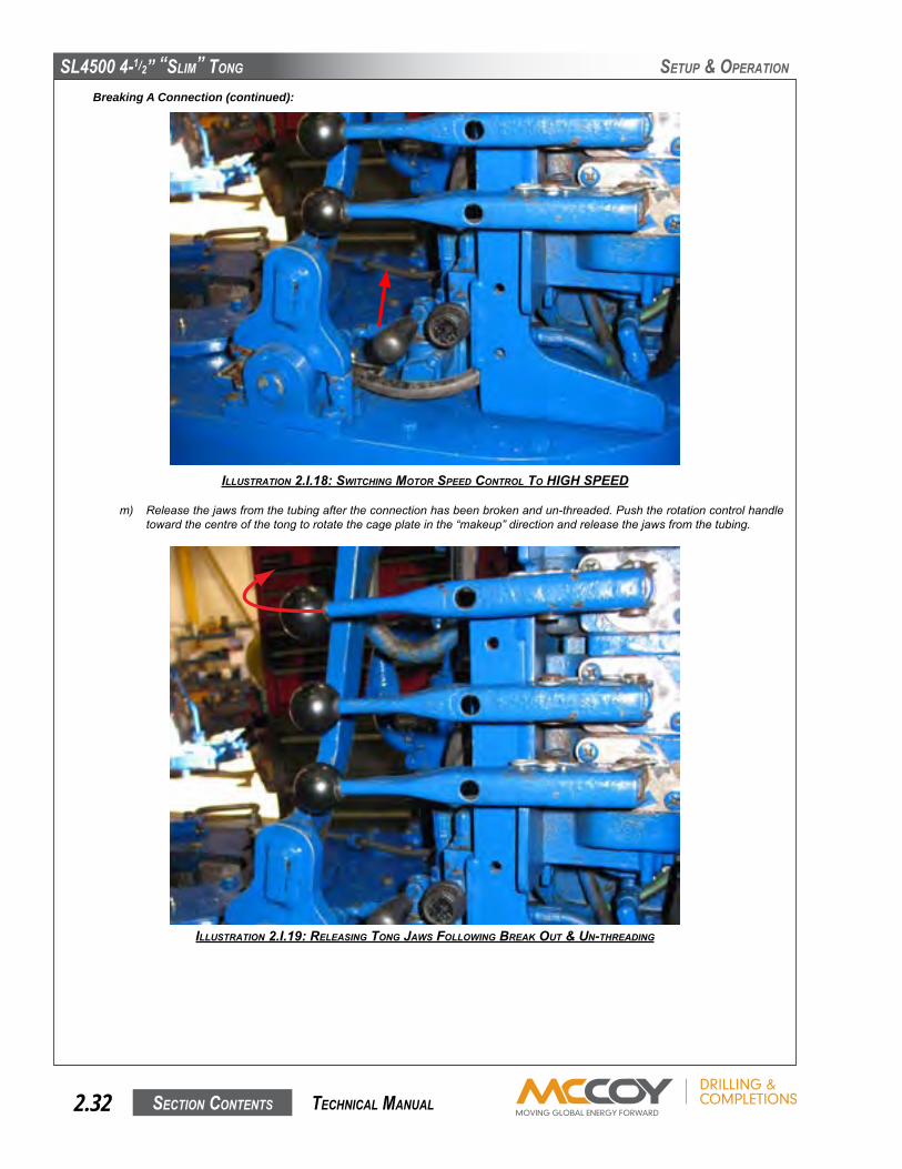
l) Pulltherotationcontrolhandleallthewayouttoensurefullbreakouttorqueisbeingdeliveredtothejoint.Whenthejointreleases,switchtohighspeedtocompletelyun-threadtheconnection:• Donotreleasetherotationcontrol• Graspthespeedcontrolknobandfirmlypullitallthewayuptothehighspeedsetting(seeIllustration2.I.18).
Releasetherotationcontrolhandlewhentheconnectioncompletelyun-threads.
SL4500 4-1/2” “SLim” Tong
SecTion conTenTS2.32 TechnicaL manuaL
SeTuP & oPeRaTion
m) Releasethejawsfromthetubingaftertheconnectionhasbeenbrokenandun-threaded.Pushtherotationcontrolhandletowardthecentreofthetongtorotatethecageplateinthe“makeup”directionandreleasethejawsfromthetubing.
IllustratIon 2.I.18: swItchIng motor speeD control to hIgh speeD
Breaking A Connection (continued):
IllustratIon 2.I.19: releasIng tong Jaws followIng Break out & un-threaDIng

SL4500 4-1/2” “SLim” Tong
SecTion conTenTS 2.33 TechnicaL manuaL
Breaking A Connection (continued):
n) Whentongjawsarefreereleasethebackupjawsbypullingthebackupclampcontrolhandleawayfromthetongtowardtheoperator.
o) Unlatchandopenthetongdoortofreetheassemblyfromthetubing.Notethatrigpersonnelmayberequiredtostabilizetheequipmentasitcompletelyreleasesfromthetubing.Guidetheassemblyawayfromthestringandusetheliftcylindercontroltolowerittothedrillfloor.
p) Useyourrig’sstandardpipehandlingprocedurestoremoveandrackthefreedtubingstand.q) Repeatsteps“g”through“p”asmanytimesasnecessarytobreakoutandun-threadthedesirednumberofconnections.
IllustratIon 2.I.20: un-clampIng Backup Jaws
IllustratIon 2.I.21: lowerIng assemBly usIng lIft cylInDer control

This page intentionallyleft blank

SL4500 4-1/2” “SLim” Tong
SecTion conTenTS 3.1 TechnicaL manuaL
mainTenance
McCoyCompletions&Drillingrecognizesthatminoron-siterepairsandmodificationsarerequiredtomaintainpeakoperatingconditionofyourequipment,ortomatchyourequipmentwiththeoperatingenvironment.Examplesofminorrepairsare
● replacementofdamagedhydraulichosesandfittings.● replacementofmalfunctioningpressuregaugesandvalves.● replacementofdoorcylinders● replacementoffasteners
AnyreplacedcomponentmustbeanidenticalcomponentsuppliedbyMcCoyCompletions&Drilling.ReplacedfastenersmustbeGrade8orequivalent,orwhateverfastenerisspecifiedbyMcCoy.
A. GENERAL MAINTENANCE SAFETY PRACTICESThepracticesidentifiedhereareintendedasaguideline.Allpersonnelareresponsibleforperformingtheirtasksinamannerthatensuresworker,equipment,andenvironmentalsafety,andmayrequiretakingadditionalstepsthatarenotidentifiedinthissection.
Equipmentmaintenanceshall beperformedonlybydesignatedqualifiedmaintenancepersonnel.Wearapprovedeyewearandfootwear,andfollowallofyourcompany’ssafetyguidelinesDonotbeginamaintenancetaskwithoutthepropertoolsormaterialsonhand,ortheproperdrawingsanddocumentationnecessary.
Scheduleplannedmaintenancewithoperatorstoavoidconflicts,unnecessarydowntime,andthedangerofaccidentalequipmentactivation.Notifyoperationswhenmaintenanceproceduresarecompleteandequipmentfunctionalityisrestored.
Isolatethelocationofthemaintenanceunderwaytopreventunawarepersonnelfrominadvertentlyexposingthemselvestoahazard.Usetape,rope,orsignagetoclearlyindicate“off-limits”area.
Replacement of large, heavy individual parts and/or heavy structural componentsmust be performed using an approved liftingdeviceofsufficientliftingcapacity.Usecarewhenattachingtheliftingdevice,andsafeguardareatoavoidendangeringpersonnelorequipment.
AllsparepartsmustmeetorexceedOEMspecificationsinordertomaintainequipmentintegrity,especiallyprotectiveequipment
McCoyrecommendsthatdisconnectionofhydraulicconnectorsbeperformedwiththepowerunitoffandthehydrauliccircuitdepres-surized.
Your equipment usesmaterials thatmay be harmful to the environment if improperly disposed of (hydraulic fluid, grease, etc.).Disposeofallmaterialsaccordingtoyourcompany’sproscribedenvironmentalprotectionregulations.
B. CLEANINGCleantongthoroughlycleanedwithagoodpetroleum-basedcleaningagentaftereachjob,priortostorage.Farrrecommendsthatthemotorandvalveassemblybeperiodicallyremoved,alongwiththetoptongplate,sothatguides,rollersandgearscanbeprop-erlycleaned.Ensurethatcleaningsolventsandchemicalsarecapturedtopreventenvironmentalcontamination,anddisposeofallmaterialsaccordingtoyourcompany’sproscribedenvironmentalprotectionregulations.
C. PREVENTIVE MAINTENANCE PRACTICESRegularmaintenanceprogramsarenecessary,andmustbeestablished toassuresafe,dependableoperationofyourHydraulicTubularConnectionSystemandtoavoidcostlybreakdownmaintenance.Thefollowingmaintenanceproceduresprovideinformationrequiredtoproperlymaintainyourequipment.Yourequipmentmayrequiremore,orlessmaintenancedependinguponthefrequencyofuseandthefieldconditionsunderwhichyourequipmentoperates.McCoyhasalsoprovidedrecommendedmaintenancecheck-lists.Theintervalsinthemaintenancechecklistsaredesignedforequipmentoperatingat10°Cto35°Cambienttemperaturefor10hoursperday.McCoyrecommendsthattheinspectionandmaintenanceproceduresinthissectionbeperformedasrecommendedinthemaintenancechecklists,orinconjunctionwithyourmaintenanceforeman’sexperienceandbestestimateofwhenyourequip-mentisdueforthismaintenance.
Purchasedcomponentsincludedwithyourhydraulictubularconnectionequipment(forexample:motors,valves,etc.)mayspecifymaintenancetasksandintervalsoverandabovewhatMcCoyrecommendsaspartoftheirrecommendedprocedures.Usersofthisequipmentmaychoosetoperformorignoretheseadditionaltasksattheirdiscretion.
Prematurefoulingofparticulatefilterswithinyourprimemoverorancillaryhydraulicpowerunitrequiresimmediatehydraulicfluidlaboratoryanalysistopreventprematurewearofhydraulicsystemduetohighlevelsofwearmetalsinthefluid.
McCoyCompletions&Drillingrecommendstrackingallmaintenanceactivityincludingthelubricationschedule.Thismaybeasimpleaskeepingapaperlog,orusingasoftware-basedmaintenancetrackingutility.Amaintenancelogisavaluabletoolthatcanbeusedforeasilyretrievingmaintenancehistoryoridentifyingtrendsthatrequirecorrection.
SL4500 4-1/2” “SLim” Tong
SecTion conTenTS3.2 TechnicaL manuaL
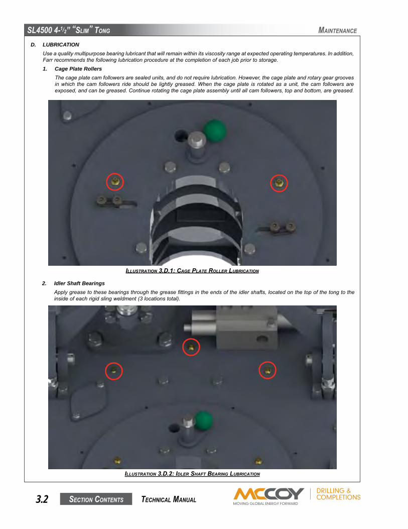
D. LUBRICATIONUseaqualitymultipurposebearinglubricantthatwillremainwithinitsviscosityrangeatexpectedoperatingtemperatures.Inaddition,Farrrecommendsthefollowinglubricationprocedureatthecompletionofeachjobpriortostorage.
1. Cage Plate RollersThecageplatecamfollowersaresealedunits,anddonotrequirelubrication.However,thecageplateandrotarygeargroovesinwhich thecam followers rideshouldbe lightlygreased.When thecageplate is rotatedasaunit, thecam followersareexposed,andcanbegreased.Continuerotatingthecageplateassemblyuntilallcamfollowers,topandbottom,aregreased.
2. Idler Shaft BearingsApplygreasetothesebearingsthroughthegreasefittingsintheendsoftheidlershafts,locatedonthetopofthetongtotheinsideofeachrigidslingweldment(3locationstotal).
IllustratIon 3.D.1: cage plate roller luBrIcatIon
IllustratIon 3.D.2: IDler shaft BearIng luBrIcatIon
mainTenance
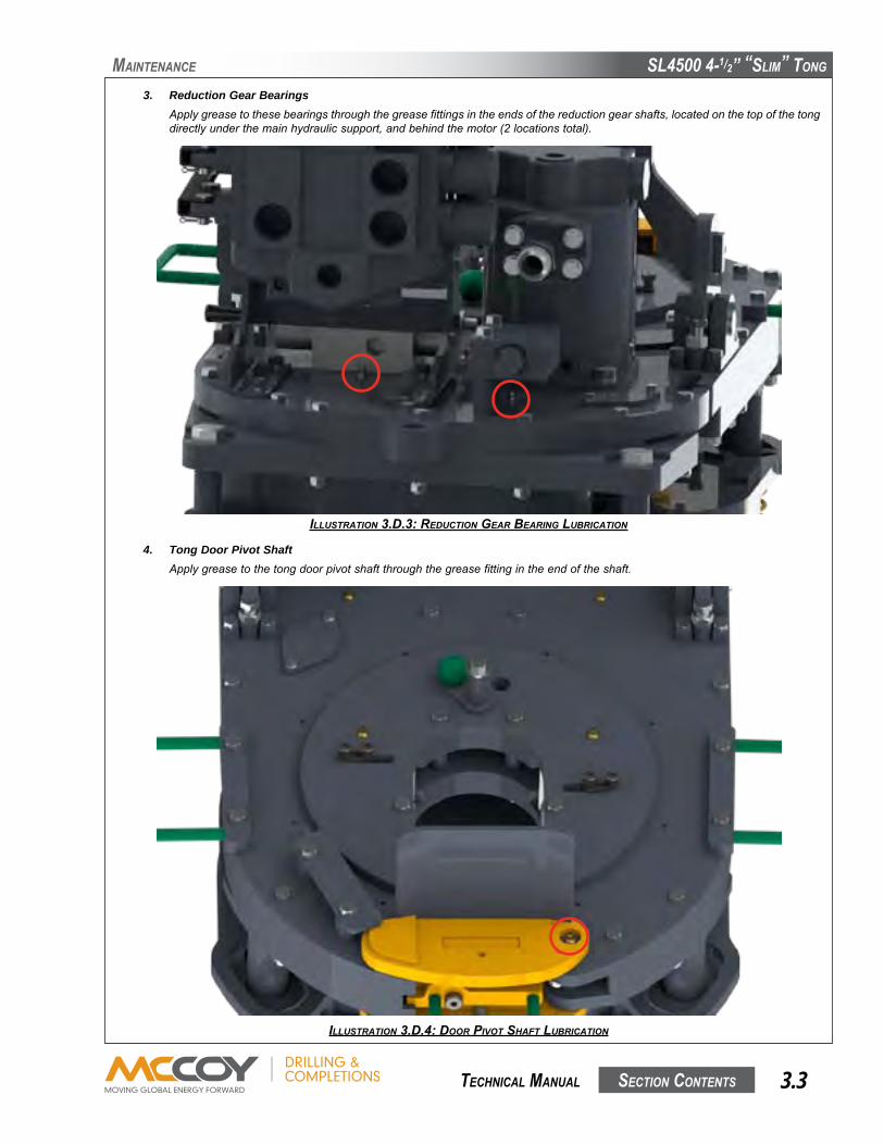
SL4500 4-1/2” “SLim” Tong
SecTion conTenTS 3.3 TechnicaL manuaL
3. Reduction Gear BearingsApplygreasetothesebearingsthroughthegreasefittingsintheendsofthereductiongearshafts,locatedonthetopofthetongdirectlyunderthemainhydraulicsupport,andbehindthemotor(2locationstotal).
mainTenance
4. Tong Door Pivot ShaftApplygreasetothetongdoorpivotshaftthroughthegreasefittingintheendoftheshaft.
IllustratIon 3.D.4: Door pIvot shaft luBrIcatIon
IllustratIon 3.D.3: reDuctIon gear BearIng luBrIcatIon

SL4500 4-1/2” “SLim” Tong
SecTion conTenTS3.4 TechnicaL manuaL
mainTenance
5. Tong Door LatchApplyathinlayerofgreasetothetongdoorlatchclaws,andthetopandbottomofthedoorlatchposttoenablesmoothlatch-ingaction.
6. Jaw LubricationApplyathinlayerofgreasetothemetal-to-metalcontactsurfacesofthetongandbackupjawstoenablethemtoslidesmoothly.
IllustratIon 3.D.5: Door latch & post luBrIcatIon
IllustratIon 3.D.6: Jaw assemBly luBrIcatIon

SL4500 4-1/2” “SLim” Tong
SecTion conTenTS 3.5 TechnicaL manuaL
mainTenance
7. Backup / Load Cell LubricationGreasemustbeaddedtobothsidesoftheinterfaceoftheloadcellandtherearlegofthebackup.
IllustratIon 3.D.7: loaD cell luBrIcatIon
E. ADJUSTMENTS1. Brake Band Adjustment (See Illustration 3.E.1):
Thebrakebandsmustbeperiodicallyadjustedtocontinuetoprovidesmoothandefficient jawcamaction. If thecageplateturnswith therotarygear, the jawswillnotcamproperlyand, therefore,willnotbiteon the tubingorcasing.Tightening thebrakebandagainstthecageplateswillincreasefrictionalresistance,allowingjawstocamproperlyandgripthecasing.Adjustthebrakebandusingtheadjustmentnutandboltsetasshown in the illustrationbelow.Donotover tighten,asthiscausesexcessiveweartothebrakebands.
Ifexcessivetighteningisrequiredfortongoperation,removethebrakebandandinspectforwearorforeigndebris/excessivegrease.Cleaningmayberequiredtorestorethebrakelining.Replacethebrakebandifthethicknessislessthan.10”(2.5mm)atanyeffectiveportionofthebrakelining.
IllustratIon 3.e.1: Brake BanD aDJustment
Brake Band
Brake Band Adjustment Nut & Bolt

SL4500 4-1/2” “SLim” Tong
SecTion conTenTS3.6 TechnicaL manuaL
mainTenance
2. Safety Door Switch Adjustment:Thesafetydoorswitchisintendedtointerrupthydraulicpowertothemotorwhenthetongdoorisopened,orevenslightlyajar.Thisisacriticalsafetysystem,andproperadjustmentisnecessarytomaintaintheintendedfunction.Iftherotarygeardoesnotimmediatelyandcompletelystoprotatingwhenthedoorisopened,removethetongfromserviceandperformthefollowingadjustments:1. Setthetongupinacontrolledtestingenvironmentwithoutconnectinghydraulicpower.2. Openthetongdoorandcheckoperationofthesafetydoorswitchplunger.Depressandallowitspringbackseveraltimes
toensuresmoothoperation.Iftheplungerbindsorjams,removethecontrolcableguidemountatthedoorend,removethecontrolcableandplunger,andthoroughlycleanandlubricatetheplungerandcontrolcablebeforereinstalling.
3. Testthecontrolcableaftercleaningandreinstallation.Thecableendshouldspringbackwhendepressed.Ifthecabledoesnotsmoothlyspringback,replacethecontrolcable.
4. Followingreinstallationtheplungershouldextend3/4ofaninchfromtheendofthecontrolcableguidemount.
IllustratIon 3.e.2: safety Door plunger aDJustment 01
IllustratIon 3.e.3: safety Door plunger aDJustment 02
Adjustplungerpositionusingthepositioningnutandlockingnutonthecontrolcablebeforeproceeding.Loosenthelockingnut,andadjustthepositioningnutuntiltheplungerextensionmeasuresapproximately3/4”.Whenpositionoftheplungerisset,tightenthelockingnut.Notethatalthoughthefollowingillustrationshowsthetongdoorclosed,theplungerextensionmustbeperformedwiththedooropen.
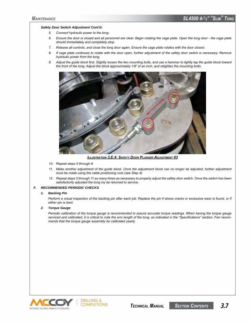
SL4500 4-1/2” “SLim” Tong
SecTion conTenTS 3.7 TechnicaL manuaL
mainTenance
Safety Door Switch Adjustment Cont’d:5. Connecthydraulicpowertothetong.6. Ensurethedoorisclosedandallpersonnelareclear.Beginrotatingthecageplate.Openthetongdoor-thecageplate
shouldimmediatelyandcompletelystop.7. Releaseallcontrols,andclosethetongdooragain.Ensurethecageplaterotateswiththedoorclosed.8. Ifcageplatecontinuestorotatewiththedooropen,furtheradjustmentofthesafetydoorswitchisnecessary.Remove
hydraulicpowerfromthetong.9. Adjusttheguideblockfirst.Slightlyloosenthetwomountingbolts,anduseahammertolightlytaptheguideblocktoward
thefrontofthetong.Adjusttheblockapproximately1/8”ofaninch,andretightenthemountingbolts.
10. Repeatsteps5through8.11. Makeanotheradjustmentoftheguideblock.Oncetheadjustmentblockcannolongerbeadjusted,furtheradjustment
mustbemadeusingthecablepositioningnuts(seeStep4).12. Repeatsteps5through11asmanytimesasnecessarytoproperlyadjustthesafetydoorswitch.Oncetheswitchhasbeen
satisfactorilyadjustedthetongmybereturnedtoservice.
F. RECOMMENDED PERIODIC CHECKS1. Backing Pin
Performavisualinspectionofthebackingpinaftereachjob.Replacethepinifstresscracksorexcessivewearisfound,orifeitherpinisbent.
2. Torque GaugePeriodiccalibrationofthetorquegaugeisrecommendedtoassureaccuratetorquereadings.Whenhavingthetorquegaugeservicedandcalibrated,itiscriticaltonotethearmlengthofthetong,asindicatedinthe“Specifications”section.Farrrecom-mendsthatthetorquegaugeassemblybecalibratedyearly.
IllustratIon 3.e.4: safety Door plunger aDJustment 03

SL4500 4-1/2” “SLim” Tong
SecTion conTenTS3.8 TechnicaL manuaL
1. Disconnectallhydrauliclinesfromthehydraulicvalveassemble,includingmainmotorlines,backup,safetydoor,anddrains.2. Removethefour3/8”hexcapscrewssecuringthevalveassemblytothetopplate,andliftvalveassemblyaway.3. Ifnotalreadydone,disconnectandremoveloadcellandloadcellspacerweldment.
REMOVAL OF BACKUP4. Constructasupportthatwillsupporttheentireweightofthebackupassembly.5. Liftthetongandbackupandlowerontostructureconstructedinstep1untiltheweightofthebackupiscompletelyremovedfrom
thefrontlegandrearsupportsprings.6. Freethefrontlegspringsbyremovingthe3/8”hexcapscrewthatsupportsthebottomspringspacers.Removethecotterpins
securingtherearlegsupportrod,andremovethesupportrod.7. Liftthetong,andfrontandrearlegs,upandawayfromthebackup.Usecautionnottolosethespringsandtopspringwashers,
whichwillcomeloosefromthefrontlegswhenthetongislifted.
REMOVAL OF LEG ASSEMBLIES8. Setthetongandlegassemblyontoaflatsurface.Ensurethatthemajorityoftheweightremainssupportedbytherigidslingand
thecrane.Removethetwo3/4”x5”hexbolts,lockwashers,and3/4”nutssecuringtherearoftherearlegassembly,andthetwo3/4”x3-1/2”hexboltsandlockwasherssecuringthefrontoftherearlegassembly.
9. Removethefastenerssecuringeachfrontlegmounttothebottomplate.10. Liftthetongupandawayfromthelegs-ensurethatnoneofthelegassembliesorweldmentstoppleoverwhenthetongislifted
away.Placethetongonasuitablesurfacethatwillsupporttheentireweightofthetongandallowaccesstothebottomofthetong.
11. Removethetwoeight3/8”x3-1/2”capscrews,lockwashers,andnutssecuringtherigidslingassemblytothetopplate(fourperside).Theentirerigidslingassemblymaynowbeliftedawayfromthetong.
REMOVAL OF TOP PLATE12. Ifnotalreadydone,completethedisconnectionofallhydrauliclinesfromthemotor.Removethefour1/2”capscrewssecuring
themotortothetopplate,andliftthemotorandmotorgearaway.13. Ifnotalreadydone,removethetwojawassembliesfromthetong.14. Removethetwoexternalsnapringsfromthedoorpivotshaft.Removethedoorpivotshaft-ifnecessary,useahammeranda
softmetaldrivetotaptheshaftout.Removethedoorassembly.15. Removethedoorlatchshaftthesamewaythepivotshaftwasremoved.16. Ensurethesafetydoorpush-pullcablehasbeenfreedatthehydraulicvalveend.Removethefastenerssecuringthesafetydoor
actuatorandpush-pullassemblytothetopplate,andremovetheentireactuatorassembly.
G. OVERHAUL PROCEDURESThetongmaybeoverhauledfollowingthedisassemblyinstructionsinthefollowingproceddure.Accesstothegeartrainispossiblebyremovingthetopplateofthetong.
mainTenance
ALL MAINTENANCE AND OVERHAUL SHOULD BE PERFORMED FROM THE TOP. THE BOTTOM PLATE OF THE TONG IS TYPICALLY WELDED TO THE SIDE BODY AND CANNOT BE REMOVED.
REPLACEMENT FASTENERS (BOLTS, NUTS, CAP SCREWS, MACHINE SCREWS, ETC.) USED DURING MAINTENANCE OR OVERHAUL MUST BE GRADE 8 OR EQUIVALENT.
THE CAGE PLATE BOLTS ARE THE ONLY ITEMS FASTENING THE BOTTOM CAGE PLATE TO THE TONG. SUPPORT THE BOTTOM CAGE PLATE FROM BELOW PRIOR TO REMOVING CAGE PLATE BOLTS IN ORDER TO PREVENT DAMAGE TO THE BOTTOM CAGE PLATE OR PERSONAL INJURY TO THE MECHANIC
17. Removethefourcageplatebolts,washers,andnuts,andthefourcageplatespacers.Thecageplatesmaynowberemoved.Thereisnoneedtoremovethebackingpinassemblyfromthetopcageplateunlessmaintenanceonthebackingpinisrequired.
18. Removethetwo3/8”x3-1/2”boltsfromthecenterofthetong,justbehindthecageplateopening.Notethatoneofthesetwoboltsetssecuresthebrakebandretainertothebottomplate.
19. Removethethree3/8”x5”hexbolts,3/8”lockwashers,and3/8”hexnutsthatsecurethebottomgearboxcovertothetopplate.
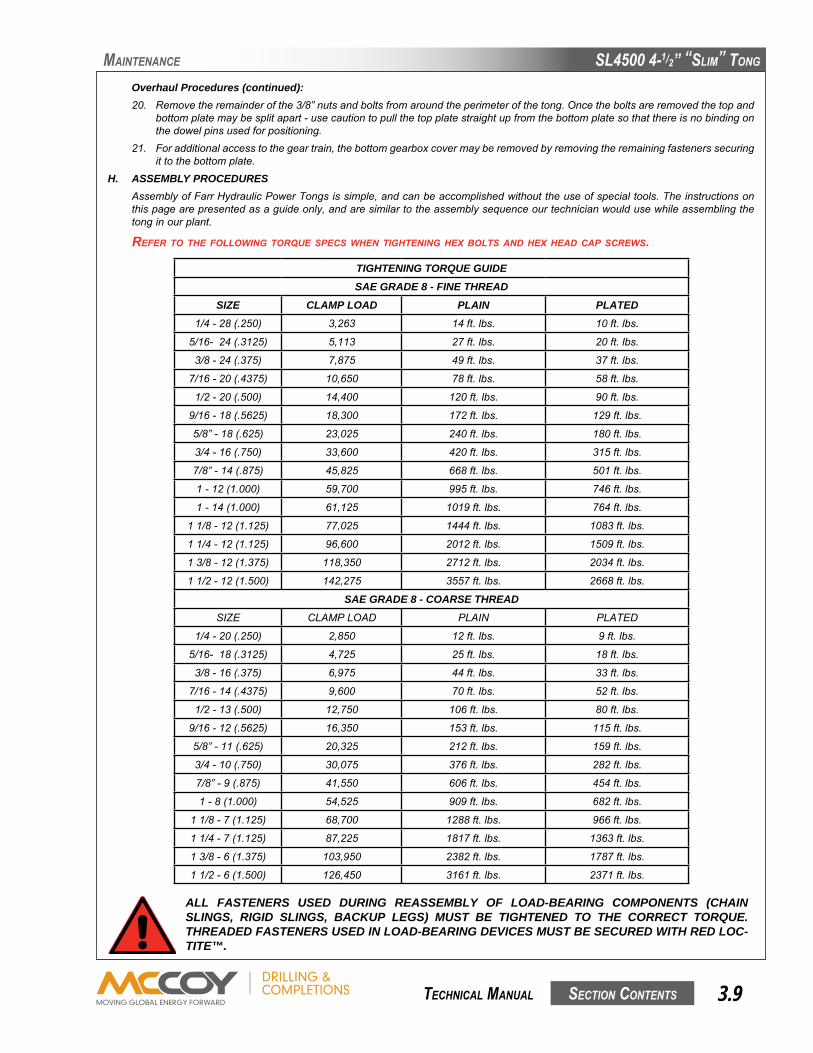
SL4500 4-1/2” “SLim” Tong
SecTion conTenTS 3.9 TechnicaL manuaL
Overhaul Procedures (continued):20. Removetheremainderofthe3/8”nutsandboltsfromaroundtheperimeterofthetong.Oncetheboltsareremovedthetopand
bottomplatemaybesplitapart-usecautiontopullthetopplatestraightupfromthebottomplatesothatthereisnobindingonthedowelpinsusedforpositioning.
21. Foradditionalaccesstothegeartrain,thebottomgearboxcovermayberemovedbyremovingtheremainingfastenerssecuringittothebottomplate.
H. ASSEMBLY PROCEDURESAssemblyofFarrHydraulicPowerTongsissimple,andcanbeaccomplishedwithouttheuseofspecialtools.Theinstructionsonthispagearepresentedasaguideonly,andaresimilartotheassemblysequenceourtechnicianwouldusewhileassemblingthetonginourplant.
refer to the followIng torque specs when tIghtenIng hex Bolts anD hex heaD cap screws.
mainTenance
ALL FASTENERS USED DURING REASSEMBLY OF LOAD-BEARING COMPONENTS (CHAIN SLINGS, RIGID SLINGS, BACKUP LEGS) MUST BE TIGHTENED TO THE CORRECT TORQUE. THREADED FASTENERS USED IN LOAD-BEARING DEVICES MUST BE SECURED WITH RED LOC-TITE™.
TIGHTENING TORQUE GUIDESAE GRADE 8 - FINE THREAD
SIZE CLAMP LOAD PLAIN PLATED1/4-28(.250) 3,263 14ft.lbs. 10ft.lbs.
5/16-24(.3125) 5,113 27ft.lbs. 20ft.lbs.
3/8-24(.375) 7,875 49ft.lbs. 37ft.lbs.
7/16-20(.4375) 10,650 78ft.lbs. 58ft.lbs.
1/2-20(.500) 14,400 120ft.lbs. 90ft.lbs.
9/16-18(.5625) 18,300 172ft.lbs. 129ft.lbs.
5/8”-18(.625) 23,025 240ft.lbs. 180ft.lbs.
3/4-16(.750) 33,600 420ft.lbs. 315ft.lbs.
7/8”-14(.875) 45,825 668ft.lbs. 501ft.lbs.
1-12(1.000) 59,700 995ft.lbs. 746ft.lbs.
1-14(1.000) 61,125 1019ft.lbs. 764ft.lbs.
11/8-12(1.125) 77,025 1444ft.lbs. 1083ft.lbs.
11/4-12(1.125) 96,600 2012ft.lbs. 1509ft.lbs.
13/8-12(1.375) 118,350 2712ft.lbs. 2034ft.lbs.
11/2-12(1.500) 142,275 3557ft.lbs. 2668ft.lbs.
SAE GRADE 8 - COARSE THREADSIZE CLAMPLOAD PLAIN PLATED
1/4-20(.250) 2,850 12ft.lbs. 9ft.lbs.
5/16-18(.3125) 4,725 25ft.lbs. 18ft.lbs.
3/8-16(.375) 6,975 44ft.lbs. 33ft.lbs.
7/16-14(.4375) 9,600 70ft.lbs. 52ft.lbs.
1/2-13(.500) 12,750 106ft.lbs. 80ft.lbs.
9/16-12(.5625) 16,350 153ft.lbs. 115ft.lbs.
5/8”-11(.625) 20,325 212ft.lbs. 159ft.lbs.
3/4-10(.750) 30,075 376ft.lbs. 282ft.lbs.
7/8”-9(.875) 41,550 606ft.lbs. 454ft.lbs.
1-8(1.000) 54,525 909ft.lbs. 682ft.lbs.
11/8-7(1.125) 68,700 1288ft.lbs. 966ft.lbs.
11/4-7(1.125) 87,225 1817ft.lbs. 1363ft.lbs.
13/8-6(1.375) 103,950 2382ft.lbs. 1787ft.lbs.
11/2-6(1.500) 126,450 3161ft.lbs. 2371ft.lbs.

SL4500 4-1/2” “SLim” Tong
SecTion conTenTS3.10 TechnicaL manuaL
NOTE ON INSTALLATION PRACTICES: Ensure all bearings are liberally greased before installing over a shaft or into gears or bearing caps. When inserting a shaft through a support roller assembly ensure shaft is greased. Also ensure all meta-to-metal contact in the gear train is adequately greased.
When graphics are not used in the assembly process, please refer to the relevant exploded diagrams in Section 5.
1. Positionthetongbodygearcaseonasuitablestationarysupportsuchthatthebottombodyplateisaccessible.2. Assembleseveninnerring/needlebearingassemblies-pressseveninnerringsintosevenneedlebearings.3. Pressoneofthebearingassembliesassembledinstep2intolargereductiongear(PN101-3292)followedbyabearingspacer
(PN101-3812)andasecondbearingassembly.4. Orientthegearassemblyfromstep3sothatthesmallergearisfacingup.Slidegearshaft(PN101-3296)intothegearassem-
bly,makingsurethethreadedholeinthetopoftheshaftisfacingup,centeringinthegearassemblyasbestasable.5. Placeathrustwasher(PN02-E0001)overeachendofthegearshaft,andthenplacethebottom(non-threaded)endofthegear
shaftintothegearboxcover(PN101-3317).6. Placethree3/8”x3/4”dowelpinsintotheirrespectivelocationsinthesidewallofthegearboxcover,andfastenthegearbox
covertothebottomofthebottomplatewithfour3/8”NCx2-1/2”hexcapscrewsand3/8”lockwashers
mainTenance
IllustratIon 3.h.1: gearBox cover InstallatIon
7. Pressoneofthebearingassembliesassembledinstep2intothesmallerreductiongear(PN101-3291)followedbyabearingspacer(PN101-3812)andasecondbearingassembly.
8. Orientthegearassemblyfromstep7sothatthesmallergearisfacingdown.Slidegearshaft(PN101-3296)intothegearas-sembly,makingsurethethreadedholeinthetopoftheshaftisfacingup,centeringinthegearassemblyasbestasable.
9. Placeathrustwasher(PN02-E0001)overeachendofthegearshaft,andthenplacethebottom(non-threaded)endofthegearshaftintothegearboxcover(PN101-3317).
10. PressonebearingassemblyassembledinStep2intoeachofthethreeidlergears(PN101-3293).Slideanidlergearshaft(PN101-3297)througheachidlergearassemblyandcenterinthegearassembliesaswellasable.Slideathrustwasher(PN02-E0001)overeachend,andplacethebottom(un-threaded)endsoftheshaftsthroughthebottomplate(seeIllustration3.H.2).
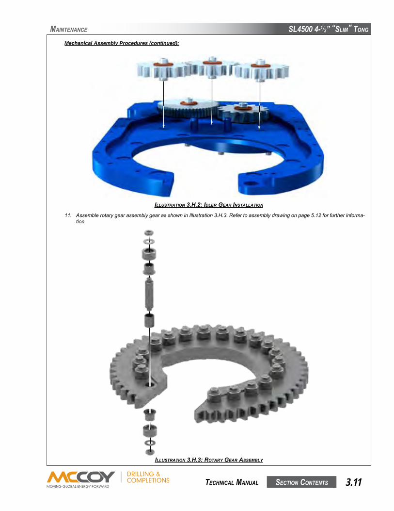
SL4500 4-1/2” “SLim” Tong
SecTion conTenTS 3.11 TechnicaL manuaL
Mechanical Assembly Procedures (continued):
11. AssemblerotarygearassemblygearasshowninIllustration3.H.3.Refertoassemblydrawingonpage5.12forfurtherinforma-tion.
mainTenance
IllustratIon 3.h.2: IDler gear InstallatIon
IllustratIon 3.h.3: rotary gear assemBly

SL4500 4-1/2” “SLim” Tong
SecTion conTenTS3.12 TechnicaL manuaL
Mechanical Assembly Procedures (continued): 12. Installeight“button”guides(PN101-3389)intothebottomplateusingone1/4”NCx1/2”hexsocketflatheadmachinescrew
perbutton.Installtheremainingeight“button”guidesontheundersideofthetopplate.
13. Installrotarygearassemblyoverthe“button”guidesinthelowerplate.Ensuretherotarygearisinstalledwiththebackingpinslotsfacingup.
14. Insertthree3/8”x1”dowelpinsintotheirrespectivelocationsinthelowerbodyplate.15. Lowerthetopplateintopositionoverthebottomplate.Ensuretheplateisloweredashorizontallyaspossibletopreventbinding
onthedowelpins.16. Securethetopplatetothebottomplateandgearboxwith3/8”NCx3”hexcapscrews(indicatedbygreen)and3/8”NCx5”
hexcapscrews(indicatedbyred),and3/8”NChexnutsand3/8”lockwashers.
mainTenance
IllustratIon 3.h.4: “Button guIDe” InstallatIon
IllustratIon 3.h.5: maIn BoDy fastener placement
17. Positionthelowercageplate(PN101-3304)againstthebottomsideoftherotarygearassembly,ensuringthegrooveinthecageplateengageswiththelowerrollers.Placefourcageplatespacers(PN101-3333)ontheinsideofthebottomcageplate.

SL4500 4-1/2” “SLim” Tong
SecTion conTenTS 3.13 TechnicaL manuaL
Mechanical Assembly Procedures (continued): 18. Placethetopcageplate(PN101-3303)overthetopoftherotarygearassembly,ensuringthegrooveinthecageplateengages
therollersonthetopoftherotarygear.Securethetopandbottomcageplateswithfour3/8”NCx4-1/2”hexcapscrews,lockwashers,andhexbolts.
19. Attachthemotorgeartothemotorshaft.Orientthemotorgearsothatthesmallerdiameterofthegearistowardthemotorratherthantheendofthemotorshaft.Thegearshouldbepositioned7/16”fromtheflatendofthemotorshaft-securewithtwo1/4”NCx3/8”conepointhexsocketheadsetscrews.
20. Slidethemotorthrustwasher(PN02-E0009)overtheendofthemotorshaft.Mountthemotortothetopplate-theendofthemotorshaftshouldrestwithinthecircularcutoutinthebottomplate.Securethemotortothetopplatewithfour1/2”NCx1-1/2”hexcapscrewsand1/2”lockwashers.
21. Insertthedoorlatchpin(PN101-3306)intoitslocationandsecureontheinsidesofthetopandbottomplatewithtwoexternalsnaprings(PN02-E0004).
22. Attachthedoorlatchweldmenttothedoorweldment(seeIllustration3.H.6):i. Insertapositioning1/4”x3/4”dowelpinintothefrontofthedoorweldmentii Slidethelatchspring(C0460-0050-1125)overthepinweldedtothefrontofthebottomdoorplateinthedoorweldment.iii. Attachthelatchweldment(PN101-3530)tothedoorweldmentwitha3/8”x3/4”hexsocketshoulderbolt.Ensureawave
spring(PN02-9267)isinsertedbetweenthelatchweldmentandthedoorweldmentwhenthelatchweldmentisbeingat-tached.
mainTenance
23. Insertashoulderbushing(PN02-E0003)intothetopofthetopplate,andthebottomofthebottomplate,wherethedoorpinislocated.
IllustratIon 3.h.6: Door latch welDment InstallatIon
Positioning Dowel Pin
CompressionSpring
WaveSpring

SL4500 4-1/2” “SLim” Tong
SecTion conTenTS3.14 TechnicaL manuaL
Mechanical Assembly Procedures (continued): 24. Threadthedoordetentintothebottomofthetopplateuntilthespring-loadedbuttonprotrudesthroughthetopplate.Securethe
detentfromthebottomwitha3/8”NChexnut.
mainTenance
IllustratIon 3.h.7: Door Detent InstallatIon
25. Positionthedoor&latchassemblyassembledinStep22initslocation,andinsertthedoorpinfromthetopthroughthedoor,theshoulderbushings,andthetopandbottomplate.Securethedoorpinwithtwo3/4”externalsnaprings(PN02-E0004)totheinsidesoftheshoulderbushings.
26. Attachthesafetydoorcableguideholder(PN101-4235)andcover(PN101-4237)tothetopplatewithone3/8”NCx1-3/4”hexcapscrewand3/8”lockwasher,andone3/8”NCx4-1/2”hexcapscrewandlockwasher.Notethatthesecondfastenerextendsthroughthetopandbottomplatesandissecuredonthebottomwitha3/8”lockwasherand3/8”NChexnut.
27. Connectthetwobrakebandweldmentstogether,usinga3/8”NCx3-1/4”hexcapscrew,3/8”lockwasher,and3/8”NChexnut.EnsurethataBelleville8-washerassembly(PN101-3272ASSEM)isplacedbetweentheheadofthecapscrewandthebrakebandweldment.
28. Securethebrakebandassemblytothebottomplateusingtwo3/8”x16/25”shoulderboltsatthebrakebandpivots,andthebrakebandretainer(101-3975).Securethebrakebandretainertothebottomplateusinga3/8”NCx3-1/2”hexcapscrew,insertedfromthetopplate,a3/8”lockwasher,anda3/8”NChexnut.
29. Securefourrigidslingliftinglugstothetopplateusingtwo3/8”NCx3-1/2”hexcapscrews,two3/8”lockwashers,andtwo3/8”NChexnutsperlug(secureboltsfromunderneaththetong).
30. Slidethebackingpinretainer(PN101-4040)overthebackingpincenterpivotspacer(PN101-4038),andsecurethepivotspacertothetopcageplateusinga3/8”NCx2-1/2”hexcapscrewand3/8”flatwasher.
31. Thread3/8”NCx1-1/2”threadedstud(PN101-4058)intothebackingpin(PN101-4039).Attachthebackingpintothebackingpinretainerusingthebackingpinknob(PN02-0017).
32. Attachtherigidslingweldmenttotherigidslingbracketsusingonerigidslingpin(PN02-E0008)perside.Secureeachrigidslingpinwitha0.125”x2.5”hitchpins.Ensurea3/4”flatwasherisinstalledbetweentherigidslingweldmentandeachrigidslinglug(totaloffour).
33. Settherearlegweldment(PN101-3883)onaflatconcretesurface,inaclearareaasclosetothetongassemblyaspossible.Liftthetongwithacrane,andloweritontotherearlegweldment,ensuringmostoftheweightremainssupportedbythecrane.Securetherearlegweldmenttothetongusingtwo3/4”NCx5”hexbolts,3/4”lockwashers,andtwo3/4”hexnutsthroughthetwomountingholesintherear,one3/4”NCx3-1/2”hexboltand3/4”lockwasher,andone3/4”NCx2-1/2”hexboltand3/4”lockwasher.
SL4500 4-1/2” “SLim” Tong
SecTion conTenTS 3.15 TechnicaL manuaL
Mechanical Assembly Procedures (continued): 34. Attachthefrontlegweldmentstothetongusingtwo3/8”NCx3-1/2”hexcapscrews,3/8”lockwashers,and3/8”NChexnuts
perside.35. Supportthebackuponastructurethatwillsupportitscompleteweight,atleast16inches(40cm)offthefloor.36. Setthetongandlegassemblydownoverthebackup,guidingthefrontlegsthroughthefrontlegholesonthebackupandguid-
ingtherear“paddle”onthebackupbetweentheuprightsintherearlegweldment.Beforethefrontlegsreachthefloor,slidealarge,1-5/8”washeroverthebottomofeachlegfollowedbyafrontlegspring(PN02-0920)andabottomspringsupport(PN101-4339).Securethelegspringswitha3/8”NCx2”hexcapscrewand3/8”NChexnut.
37. Inserttwobackupsupportplateweldments(PN101-3885)betweentheuprightsintherearlegweldmentsothattheyopposeeachother(seeexplodeddiagramPp.6.28-6.29).Inserttworearlegsprings(PN997-13)betweenthetwosupportplates,andinserttherearlegsupportrod(PN101-3891)beneaththetwoplates.Securetherodwithtwosmallhitchpins.
38. Liftthetongandbackupassemblyawayfromanysupportingstructuresandplaceflatonasturdysurface.39. Pre-mountthemainvalvebanktothevalvemountweldment(PN101-4101)usingthree1/2”NCx4-1/2”hexbolts,1/2”narrow
flatwashers,and1/2”NCthinnylocknuts.40. Installthevalvemountweldmentonthetopplatetotheleftofthemotor.Securewithfour3/8”NCx1”hexboltsand3/8”lock
washers.41. Installgreasefittingsasfollows:
i. Installtwo1/4”UNFstraightthreadgreasefittings(PN02-0097)intothetopcageplate.ii. Installa1/4”UNFstraightthreadgreasefitting(PN02-0097)inthetopendofeachgearshaft,locatedonthethetopside
ofthetong(5locationstotal).iii. Installa1/4”UNFstraightthreadgreasefitting(PN02-0097)intheendofthedoorpivotshaft.
mainTenance

SL4500 4-1/2” “SLim” Tong
SecTion conTenTS3.16 TechnicaL manuaL
mainTenance
I. DAILY INSPECTION & MAINTENANCE CHECKLIST (POWER TONG)Farrrecommendsthatthefollowinginspectionandmaintenanceproceduresbeperformedbeforeeachuse,andatleastonceperdaywhenthetongisinsteadyuse,intheorderinwhichtheyarelisted.
1. Rotatecageplate/rotarygearuntiltheopeningintherotarygearfacestowardstherearofthetong.
3. Performaninitialwashofthetonginordertoremovethemajorityofdirtandgreasebuild-up.Ensureadequatecontain-mentisinplacetopreventenvironmentalcontaminationfromresidualhydraulicfluidanddirtygrease.
4. Removetheaccesspanelonthesideofthetongdirectlyadjacenttotheshiftermechanism.
5.Useaflashlighttoperformavisualinspectionofthegeartrainthroughtheaccesspanelandtheopeningoftherotarygear.Ifgeardamageorchipsofmetalareseen,thetongshouldberemovedfromserviceandoverhauledtoavoidfurtherdamage.Replaceaccesspanelwheninspectioniscomplete.
6.Performavisualinspectionofallfastenersandprotrudingbodypieces(example:hydraulicvalvemounts,inlet&outletlinesupports,tonglegs,shifterhandlepivotlugs).Tightenorreplacelooseormissingfasteners.Farrrecommendsthatdamagedormissingbodypartsberepairedorreplacedassoonaspossible.
7.Inspectthejawsanddies.Inspectthejawrollerpinsforsignsofdamage-replacepinsifnecessary.Ifthepinsareweldedinplace,replacetheentirejawassembly.Ensurediesaresecureinthejaw-replaceworndiesifnecessary.Ensurethatthejawrollersrotatefreely.Checktoensurethesizeoftheloadedjawsmatchthesizeofcasingorpipeyouarerunning.
8.Performavisualinspectionofallliftingpoints-ifvisibledamageisseen,includingcracks,brokenlugs,distortedmetal,etc.replacedamagedpart(s)beforeplacingtonginservice.Alsoinspectallchains,master links,andturnbuckles-again,ifanydamageisnotedreplacethedamagedpart(s)beforeplacingthetonginservice.
9. Inspecttongforsignsofprematurewear,ormovingpartsthatarerubbing(baremetalwherethereusedtobepaintisagoodindicationofwear.
10. Inspectbackingpin(s).Ifcracked,broken,orbentit(they)mustbereplaced.
11.Inspecttopandbottombrakebandlinings-replaceifnecessary.Unequalwearofthebrakebandsindicatesthatthebrakebandtensionisnotevenlyadjusted.Refertothemaintenancesectionofthemanualforinstructionsonproperlyadjustingbrakebands.
12. Performavisualinspectionofallhydrauliclines.Replaceflexiblelinesiftheyappeartobecracked,fatigued,orhavevisiblesignsofwearfromcontactwitharigidobject.
13. Performavisualinspectionofallhydrauliclines.Replaceflexiblelinesiftheyappeartobecracked,fatigued,orhavevisiblesignsofwearfromcontactwitharigidobject.
DO NOT PERFORM ANY FURTHER ACTIONS OR MAINTENANCE WHILE THE TONG IS CON-NECTED TO ANY HYDRAULIC POWER SUPPLY. FARR RECOMMENDS THAT ALL HYDRAULIC LINES ARE FULLY DISCONNECTED, AND RESIDUAL HYDRAULIC PRESSURE IS BLED OFF. ENSURE ADEQUATE CONTAINMENT IS IN PLACE TO PREVENT ENVIRONMENTAL CONTAMI-NATION FROM RESIDUAL HYDRAULIC FLUID.
2.
DepressurIze hyDraulIc system In preparatIon for maIntenance:1) Rotatethetongtothe“openthroat”position.Ensuretongandbackupdoors(ifequipped)areclosed.Fullyextend
theliftcylinder2) De-energizethepowerunit.3) RepeatedlyactuatethetongmotorcontrolvalveleverINBOTHDIRECTIONStodissipateanyresidualpressurein
thevalveandmotor.4) RemovethehydraulicSUPPLYlinefromtheequipment.5) RepeatedlyactuatetheremainingcontrolvalveleversINBOTHDIRECTIONStodissipateanyresidualpressurein
theremainderofthehydrauliccontrolsystem.7) DisconnectthehydraulicRETURNlinefromtheequipment.8) Disconnectremaininghosessuchascasedrains,orlinesconnectedtotheturnscounter.
HYDRAULIC PRESSURES AS HIGH AS OPERATING PRESSURE MAY REMAIN TRAPPED IN SMALL AREAS OF THE EQUIPMENT. ENSURE ALL MAINTENANCE IS CARRIED OUT BY A QUALIFIED SERVICE TECHNICIAN, AND THAT ADEQUATE PERSONAL PROTECTIVE EQUIP-MENT IS USED TO GUARD AGAINST PRESSURE INJURIES

SL4500 4-1/2” “SLim” Tong
SecTion conTenTS 3.17 TechnicaL manuaL
23. Whilerotatingthecageplate,ensurethatthejawsproperlycam.Ifthejawsdonotcamproperly,thebrakebandsneedtobetightened.IncrementallyadjustboththetopandbottombrakebandsEQUALLYuntilpropercamactionisachieved.
14. Performacompletegreasingofthetong-refertoMaintenancesectionofthetechnicalmanual
15. Ensuremainsupplyandreturnconnectionstothetongarefullymadeup.Re-connecttheremainderofthehydrauliclines,and,ifapplicable,theelectricallinetotheturnscounter.
FAILURE TO ENSURE THAT THE SELF-SEALING SUPPLY AND RETURN LINES ARE FULLY MADE UP MAY RESULT IN CATASTROPHIC EQUIPMENT FAILURE.
NEVER OPERATE YOUR EQUIPMENT WITH A BYPASSED OR MALFUNCTIONING SAFETY DOOR
Ifusingastand-alonepowerunit,startitnow-refertothepowerunittechnicalmanualforstartupprocedures.Listentopowerunitforamomenttoseeifthereareanyunusualmechanicalsounds(rubbing,grinding,excessivepumpnoise).Ifusingadieselunit,allowsufficienttimefortheenginetoreachoperatingtemperaturebeforeincreasingengineRPM.Onceengineiswarm,graduallyincreaseengineRPMuntiloperatingspeedisreached.
16. Ensurethatsupplypressureisatorabovethetong’sspecifiedoperatingpressure,andthatthereturnpressureislessthan350psi.
17. Performavisualinspectionofpressurizedhydrauliclines.Documentandcorrectanyhydraulicfluidleaks.
18. Performafullfunctionaltestofthetong.Reportandcorrectanyhydraulicleaksfromthehydraulicvalvebank,orfromanyhydrauliccylindersthatareused.
19.Performavisualinspectionoftheloadcell.Ifusingatensionloadcell,replaceanycracked,broken,ordistortedcom-ponentsincludinglinksandchains.Ifusingacompressionloadcell,replaceanycomponentthathasbeencrushedorotherwisedistortedthroughcompression.
20. Ifapplicable, inspect the loadcellanchorpins(tension loadcellonly).Replacetheanchorpins ifcrackingormetaldistortionisseen.
21.Ifapplicable,theweldsecuringthesingleloadcellanchortothebridgebarmainplatemustbeinspected(compressionloadcellonly).Iftheintegrityoftheweldhasbeencompromised,thetongmustberemovedfromserviceuntiltheweldisrepaired.Theloadcellbeamwillneedtobedisconnectedandremovedsotheweldisvisible.Beforere-installingthebeam,liberallygreasetheanchorpinbeforereinsertingintotheloadcellbeam.
22.Testsafetydoorfeature(ifequipped).Openthetongdoor(s),andattempttorotatethecageplateatlowspeed(lowgear)inbothdirections(makeupandbreakout).Ifcageplatebeginsrotating,thesafetydoormechanismisnotfunc-tional,andthetongmustberemovedfromserviceuntilthesafetydoormechanismcanberepaired.Ifthesafetydoorisoperatingcorrectly,cageplaterotationwillnotbeinhibitedoncethedoorisclosedandlatched.
mainTenance

SL4500 4-1/2” “SLim” Tong
SecTion conTenTS3.18 TechnicaL manuaL
J. MONTHLY MAINTENANCE CHECKLIST - POWER TONGThefollowingmaintenancechecklistisintendedasaguidelineratherthanadefinitivemaintenanceschedule.Yourequipmentmayrequiremore,orless,maintenancedependinguponthefrequencyofuse,thepercentageofmaximumtorquethatyourequipmentisroutinelysubjectedto,andthefieldconditionsunderwhichyourequipmentoperates.Farrrecommendsthatthefollowinginspectionandmaintenanceproceduresbeperformedmonthly,orinconjunctionwithyourmaintenanceforeman’sexperienceandbestestimateofwhenyourequipmentisdueforthismaintenance.
1. Rotatecageplate/rotarygearuntiltheopeningintherotarygearfacestowardstherearofthetong.
3.Cleantheexteriorofthetoolthoroughly,usingeitherwater(ifusingapressurewasherensurealow-pressurewashwandisused),oranappropriatesolvent-basedgrease-cuttingcleanersuchasVarsol.Ensureadequatecontainmentisinplacetopreventenvironmentalcontaminationfromresidualhydraulicfluid,dirtygrease,andcleaningagents.
4. Removetheaccesspanelonthesideofthetongdirectlyadjacenttotheshiftermechanism.
5.Cleantheinteriorofthetongthoroughly,usingeitherwater(donotuseapressurewasher),oranappropriatesolvent-basedgrease-cuttingcleanersuchasVarsol.Ensureadequatecontainmentisinplacetopreventenvironmentalcon-taminationfromresidualhydraulicfluid,dirtygrease,andcleaningagents.Makeanoteifanymetalshavingsormetalpiecesareflushedoutofthegeartraincavity-ifshavingsormetalpiecesareseenthetongmustbeoverhauledbeforeitisreturnedtoservice.
6. Inspectallfastenersandfastenersafetywires(ifequipped).Replaceanymissingfasteners-useGrade8boltsonlyunlessotherwisespecified.Re-torqueallexternalfastenerstoSAEspecifications.
7. Repairor replaceanydamagedormissingexternalbodyparts,suchas torquegaugemounts,hydraulicsupports,safetydoorprotectors,etc.
8.Performavisualinspectionofallfastenersandprotrudingbodypieces(example:hydraulicvalvemounts,inlet&outletlinesupports,tonglegs,shifterhandlepivotlugs).Tightenorreplacelooseormissingfasteners.Farrrecommendsthatdamagedormissingbodypartsberepairedorreplacedassoonaspossible.
9. Inspecttongforsignsofprematurewear,ormovingpartsthatarerubbing(baremetalwherethereusedtobepaintisagoodindicationofwear.
10.Inspectallpaint-locationsinwhichthepainthasbeendamagedmustberepairedpriortothetongbeingreturnedtoservice.Prepareareastobepaintedtoensuretheyarefreeofgrease,dirt,orsolvent.Touchupusingasolvent-basedacrylicpaint-“McCoyGrey”ispaintcolornumberRAL7015(contactFarrsalesforpaintnumberforcustompaintap-plications).Allowsufficienttimeforpainttodrybeforeproceeding.
11. Inspectallexternalwelds.Anyweldthatiscrackedorseparatingmustberepairedandrepaintedbeforereturningthetongtoservice.
DO NOT PERFORM ANY FURTHER ACTIONS OR MAINTENANCE WHILE THE TONG IS CON-NECTED TO ANY HYDRAULIC POWER SUPPLY. FARR RECOMMENDS THAT ALL HYDRAULIC LINES ARE FULLY DISCONNECTED, AND RESIDUAL HYDRAULIC PRESSURE IS BLED OFF. ENSURE ADEQUATE CONTAINMENT IS IN PLACE TO PREVENT ENVIRONMENTAL CONTAMINA-TION FROM RESIDUAL HYDRAULIC FLUID.
2.
DepressurIze hyDraulIc system In preparatIon for maIntenance:1) Rotatethetongtothe“openthroat”position.Ensuretongandbackupdoors(ifequipped)areclosed.Fullyextend
theliftcylinder2) De-energizethepowerunit.3) RepeatedlyactuatethetongmotorcontrolvalveleverINBOTHDIRECTIONStodissipateanyresidualpressurein
thevalveandmotor.4) RemovethehydraulicSUPPLYlinefromtheequipment.5) RepeatedlyactuatetheremainingcontrolvalveleversINBOTHDIRECTIONStodissipateanyresidualpressurein
theremainderofthehydrauliccontrolsystem.7) DisconnectthehydraulicRETURNlinefromtheequipment.8) Disconnectremaininghosessuchascasedrains,orlinesconnectedtotheturnscounter.
HYDRAULIC PRESSURES AS HIGH AS OPERATING PRESSURE MAY REMAIN TRAPPED IN SMALL AREAS OF THE EQUIPMENT. ENSURE ALL MAINTENANCE IS CARRIED OUT BY A QUALIFIED SERVICE TECHNICIAN, AND THAT ADEQUATE PERSONAL PROTECTIVE EQUIP-MENT IS USED TO GUARD AGAINST PRESSURE INJURIES
mainTenance
SL4500 4-1/2” “SLim” Tong
SecTion conTenTS 3.19 TechnicaL manuaL
mainTenance
12.
Performavisualinspectionofallliftingpoints-ifvisibledamageisseen,includingcracks,brokenlugs,distortedmetal,etc.replacedamagedpart(s)beforeplacingtonginservice.Alsoinspectallchains,masterlinks,andturn-buckles-again, ifanydamage isnotedreplacethedamagedpart(s)beforeplacingthetong inservice.Refer toSection2Aofthetechnicalmanual(Sling/LoadBearingDeviceSafety)forinformationonrecommendedtestingandrecertification.Pleasenotethatturnbuckleswithpartnumber101-3086(shortturnbuckles)useahigh-strengthpinwhichmustbesuppliedbyFarr.
Ifusingastand-alonepowerunit,startitnow-refertothepowerunittechnicalmanualforstartupprocedures.Listentopowerunitforamomenttoseeifthereareanyunusualmechanicalsounds(rubbing,grinding,excessivepumpnoise).Ifusingadieselunit,allowsufficienttimefortheenginetoreachoperatingtemperaturebeforeincreasingengineRPM.Onceengineiswarm,graduallyincreaseengineRPMuntiloperatingspeedisreached.
23. Ensurethatsupplypressureisatorabovethetong’sspecifiedoperatingpressure,andthatthereturnpressureislessthan350psi.
24. Performavisualinspectionofpressurizedhydrauliclines.Ifanyhydraulicfittingsorhosesareleakingtheymustberepairedorreplacedbeforeproceeding.
25.Rotatetongforoneminute,stop,andreversethedirectionofrotationforanotherminute,endingwiththeopeningoftherotarygearfacingthegeartrain.De-energizethepowerunit,andperformanothergenerouslubricationofthegeartrain,includingthegearhousing.
26. Energizepowerunit.Rotatetongforoneminute,stop,andreversethedirectionofrotationforanotherminute,endingwiththeopeningoftherotarygearfacingthegeartrain.
27. De-energizethepowerunit,andperformathirdgenerouslubricationofthegeartrain,includingthegearhousing.
FAILURE TO ENSURE THAT THE SELF-SEALING SUPPLY AND RETURN LINES ARE FULLY MADE UP MAY RESULT IN CATASTROPHIC EQUIPMENT FAILURE.
“SHORT” TURNBUCKLES HAVING PART NUMBER 101-3086 EMPLOY HIGH-STRENGTH PINS WHICH MUST BE SUPPLIED BY FARR.
13.Rotatethegeartrainbyhand,anduseaflashlighttoperformavisualinspectionofthegeartrainthroughtheaccesspanelandtheopeningoftherotarygearwhilethegeartrainisbeingrotated.Ifgeardamageorchipsofmetalareseen,thetongshouldberemovedfromserviceandoverhauledtoavoidfurtherdamage.Replaceaccesspanelwheninspectioniscomplete.
14.Inspectalljawsanddiesinuseforthemaintenanceinterval.Inspectthejawrollerpinsforsignsofdamage-replacepinsifnecessary.Ifthepinsareweldedinplace,removeandquarantinethejawuntiltheweldisrepaired.Ensurediesaresecureinthejaw-replaceworndiesifnecessary.Ensurethatthejawrollersrotatefreely.
15. Inspectbackingpin(s).Ifcracked,broken,orbentit(they)mustbereplaced.
16.Inspecttopandbottombrakebandlinings-replaceifnecessary.Unequalwearofthebrakebandsindicatesthatthebrakebandtensionisnotevenlyadjusted.Refertothemaintenancesectionofthemanualforinstructionsonproperlyadjustingbrakebands.
17. Inspectdoorsprings.Ensurethespringsretainsufficientstrengthtobeabletoassisttheopeningofthedoor,andtokeepthedooropen.Thespringsshouldalsohelpto“snap”thedoorshut.
18.Inspectbackupsprings (ifapplicable).The rearextensionspringsshouldbeequallyextended,and the front legspringsshouldbeequallycompressed.Ensurethatneitheroftherearbackupspringshavebeenover-extendedandlacksufficienttensiontoadequatelysupportthebackup.Ensurethatneitherofthefrontlegspringshavebeenover-compressed,andstillretainenoughspringstrengthtosupportthefrontofthebackup.
19. Extendallhydrauliccylinders,andinspectcylinderrodsforsignsofmechanicaldamage,flaking,orrust.Farrrecom-mendsthatdamagedcylindersbereplacedpriortostorage.
20.Performavisualinspectionofallhydrauliclines.Replaceflexiblelinesiftheyappeartobecracked,fatigued,orhavevisiblesignsofwearfromcontactwitharigidobject.Ifyourtongisequippedwithrigidhydrauliclines,replaceanylinethatisdentedorappearstobestressedorcracked.
21. Generouslyfill thegeartrainhousingwithgreasethroughtheaccesspanel,andalsothroughtheopening intherotarygear.Performafulllubrication-refertoMaintenancesectionofmanualtodeterminelubricationpoints.
22. Ensuremainsupplyandreturnconnectionstothetongarefullymadeup.Re-connecttheremainderofthehydrauliclines,and,ifapplicable,theelectricallinetotheturnscounter.

SL4500 4-1/2” “SLim” Tong
SecTion conTenTS3.20 TechnicaL manuaL
28. Re-energizepowerunitandextendallhydrauliccylinders.Inspectcylinderrodsforsignsofmechanicaldamage,flaking,orrust.Farrrecommendsthatdamagedcylindersbereplaced.
29. Rotatetonginlowgearfor5minuteswhilemonitoringpressurizedsealsandhydrauliclines.Ifaseal,line,orfittingbeginstoleakwhiletongisrotating,itmustbereplacedbeforetheequipmentisreturnedtoservice.
30.Rotatetonginhighgearfor5minuteswhilemonitoringtemperatureoftopandbottombearingcaps.Ifthebearingcapsarehottothetouch(higherthanapproximately50oC)replacetheapplicablebearings.Likewiseifthetongismakingunusualnoisescheckfordamagedbearings(seeMaintenanceManualforallbearinglocations).
31.Installloadcell.Ifusingatensionloadcell,performavisualinspectionandreplaceanycracked,broken,ordistortedcomponents including linksand chains. If usinga compression load cell, replaceany component that hasbeencrushedorotherwisedistortedthroughcompression.
32. Ifapplicable,inspecttheloadcellanchorpins(tensionloadcellonly).Replacetheanchorpinsifcrackingormetaldistortionisseen.
33.Ifapplicable,theweldsecuringthesingleloadcellanchortothebridgebarmainplatemustbeinspected(compres-sionloadcellonly).Iftheintegrityoftheweldhasbeencompromised,thetongmustberemovedfromserviceuntiltheweldisrepaired.Theloadcellbeamwillneedtobedisconnectedandremovedsotheweldisvisible.Beforere-installingthebeam,liberallygreasetheanchorpinbeforereinsertingintotheloadcellbeam.
34. Inspect loadcell fordamageorsignsofstress.Checkoil level in loadcellandfill ifnecessary(refertotechnicalmanualSection7orSection8).
35.Whilerotatingthecageplate,ensurethatthejawsproperlycam.Ifthejawsdonotcamproperly,thebrakebandsneedtobetightened.IncrementallyadjustboththetopandbottombrakebandsEQUALLYuntilpropercamactionisachieved.Refertothemaintenancesectionofthemanualforinstructionsonproperlyadjustingbrakebands.
36.Performafull functionaltestofthetongincluding, ifapplicable,backupcomponents, liftcylinder,andfloatframecomponents.Reportandcorrectanyhydraulicleaksfromthehydraulicvalvebank,orfromanyhydrauliccylindersthatareused.
37.Testsafetydoorfeature(ifequipped).Beginrotatingthetongatlowspeed,andopenthetongdoor(s).Ifrotationdoesnotimmediatelystop,thisisanindicationthatthesafetydoormechanismisnotoperatingcorrectlyandthetongmustberemovedfromserviceuntilthemechanismisrepaired.Repeatthetestwhileoperatingthetongintheoppositedirection.Ifthesafetydoorisoperatingcorrectly,cageplaterotationwillnotbeinhibitedoncethedoorisclosedandlatched.
NEVER OPERATE YOUR EQUIPMENT WITH A BYPASSED OR MALFUNCTIONING SAFETY DOOR
38.Farrrecommendsthatananti-corrosiveagentsuchasTectyl®506beappliedtoallexternalunpaintedsurfaces(andchainslings)EXCEPTcylinderrods,jawrollers,androtarygearcammingsurfaces.Refertomanufacturerdatasheetsforproperapplicationandsafetyinformation.
Once all of the above maintenance checklist items have been satisfactorily completed the tool may be returned to service.
mainTenance
SL4500 4-1/2” “SLim” Tong
SecTion conTenTS 3.21 TechnicaL manuaL
mainTenance
K. DAILY INSPECTION & MAINTENANCE CHECKLIST (BACKUPS)FarrCanadarecommendsthatthefollowinginspectionandmaintenanceproceduresbeperformedbeforeeachuse,andatleastonceperdaywhenthebackupisinsteadyuse,intheorderinwhichtheyarelisted.
Donotperformanymaintenancewhilethetongandbackupassemblyisconnectedtoanyhydraulicpowersupply.FarrCanadarecom-mendsthatallhydrauliclinesarefullydisconnected,andresidualhydraulicpressureisbledoff.Ensureadequatecontainmentisinplacetopreventenvironmentalcontaminationfromresidualhydraulicfluid.
all unIts
1. Performaninitialwashofthebackupinordertoremovethemajorityofdirtandgreasebuild-up.
2. Performanexternalinspection.Checktoensuretherearenolooseormissingfasteners-replaceifnecessary.
3. Checktoseeifbackupisparalleltothetong-ifthebackupisrestingatanangle,oneofthefrontlegspringsislikelybrokenorfatiguedtothepointitmustbereplaced.
weDge Backup only
4.Removeaccesscoverfromtopplate.Performavisualinspectionottheinteriorofthebackup-useaflashlightifneces-sary.Prematurewearwheretherearemovingparts(baremetalwherethereusedtobepaint,andmetalshavingsinthegreasearegoodindicators)mayshowwhereacomponentneedstobeadjusted,orifnecessary,replaced.
5. Inspectlatchmechanismtoensurethedoorlatchplatecompletelyengagesthedoor.Adjustorreplaceifnecessary.
6. GreaseUC-300sliderpads,ramguides,doorcylinderpivots,anddoorpivots.
clIncher Backup only
4.Useaflashlighttoperformavisualinspectionoftheinteriorofthebackup-removeonesidepanelifnecessary.Prema-turewearwheretherearemovingparts(baremetalwherethereusedtobepaint,andmetalshavingsinthegreasearegoodindicators)mayshowwhereacomponentneedstobeadjusted,orifnecessaryreplaced.Replaceanyremovedpanelswheninspectioniscomplete.
5. Greaseclinchercylinderguidesusingthegreasefittingsonthetopbodyplate.
6. Ensurethesplinesontheclinchercylinderfaces,andontherearofthediearecleanandfreeofdebrisbeforeinsert-ingclincherdie.Ifdiearealreadyinstalled,ensurefastenersinthedieretainersaretightlysecured.
7. Inspectrearspringhangerassembly.Ensurealleyebolts,shackles,andcotterpinsareinplaceandingoodcondi-tion.
8. Inspectclinchercylindersforhydraulicfluidleaksoncethesystempressurehasbeenrestored.
farr-style Backup only
4. Inspectcamringgearforbrokenteeth.
5. Lubricatethecamfollowerarray.
6.Inspectthejawsanddies.Inspectthejawrollerpinsforsignsofdamage-replacepinsifnecessary.Ifthepinsareweldedinplace,replacetheentirejawassembly.Ensurediesaresecureinthejaw-replaceworndiesifnecessary.Ensurethatthejawrollersrotatefreely.Checktoensurethesizeoftheloadedjawsmatchthesizeofcasingorpipeyouarerunning.
7. Inspectfrontandrearcamcylindersupports.Repairorreplaceanypartsthatarebroken,cracked,orbent.
8. Inspectrearspringhangerassembly.Ensurealleyebolts,shackles,andcotterpinsareinplaceandingoodcondi-tion.
9. Openthebackupdoorandinspecttheconditionofthelatch.Repairorreplacedamagedlatchcomponents.Iflatchappearstobeingoodcondition,closethedoor,thentugfirmlyonittoensurethedoorremainslatched.
all unIts (after startIng power unIt)
10. Performavisualinspectionofpressurizedhydrauliclines-documentandcorrectanyhydraulicfluidleaks.
11. Performafullfunctionaltestofthebackup.Documentandcorrecthydraulicleaksfromthehydraulicvalvebank,orfromanyhydrauliccylindersthatareinuseonthebackup.
SL4500 4-1/2” “SLim” Tong
SecTion conTenTS3.22 TechnicaL manuaL
L. DAILY INSPECTION & MAINTENANCE CHECKLIST (POWER UNIT)Farrrecommendsthatthefollowinginspectionsandmaintenanceproceduresbeperformedbeforeeachuse,andatleastonceperdaywhentheequipmentisinsteadyuse,inthesequenceinwhichtheyarelisted.Rigorousinspectionandmaintenance,especiallylubrication,isessentialinordertoensurethatyourequipmentalwaysmeetsspecifications,andtopreventcatastrophicfailuresthatcanseverelydamageyourequipmentandcauseworkerinjury.
Ifusingastand-alonepowerunit,performthefollowinginspectionandmaintenanceproceduresbeforeeachuse,andatleastonceperdaywhenthepowerunitisinsteadyuse:
Donotperformanymaintenancewhilethepowerunitisenergized(electric)oriftheengineisrunning(diesel).Ensuretheelectricalsupplyislockedout,or,ifusingadieselpowersupply,ensurethattheengineislockedoutorthestartingmechanismotherwisedisabled.
DIesel only
1. Checkengineoillevels-addifnecessary
2. Checkdieselfueltank-fillifnecessary.
3. Visuallyinspectallfanbelts.
4. Activatemechanicalshut-offdevice-ensurethatshut-offswitchonengineisengagingwhenmanualshut-offswitchisactuated.
electrIc only
1.Visuallyinspectallelectricallinesandvisibleconnections.IfyourunitisNOTexplosionproof,opentheelectricalenclosureandVISUALLYinspectcontactsandconnectionsforsignsofcorrosionorarcing.Donotopenexplosion-proofenclosures.
2. Visuallyinspectmainelectricallinebetweenmainpowersourceandpowerunit.
all unIts
5. Performavisualinspectionofallparts.Checktoensuretherearenolooseormissingfasteners.
6. Checkhydraulic fluid level -ensurecold level isapproximatelyhalf-wayup thesightglasson thehydraulic fluidreservoir.
7. Performavisualinspectiontoensuretherearenohydraulicfluidleaks-correctifnecessary.
8. Checkthatthemainsupplyandreturnlinesonthehydraulicfluidreservoirarebothfullyopen.
9. Applygreasetoanygreasefittingsthatyourpowerunitmayhave.Applygreasetoeachfittinguntilgreaseisvisiblydisplacedfrombearing,orasrecommendedbyyourpowerunitmanual.
10. Ensuresupplyandreturnconnectionsatthepowerunitandattheequipmentinusearefullymadeup.
NEVER PLACE HANDS INSIDE AN ELECTRICAL ENCLOSURE UNLESS YOU HAVE CON-FIRMED THAT THE POWER HAS BEEN DISCONNECTED AND LOCKED OUT
FAILURE TO ENSURE THAT THE SELF-SEALING SUPPLY AND RETURN LINES ARE FULLY MADE UP MAY RESULT IN CATASTROPHIC EQUIPMENT FAILURE.
11. Checkhydraulicfluidfilterbackpressure(mustbedonewhilefluidiscirculating).Ifneedleonindicatorgaugeisintheredzone,thefiltershouldbechangedthenexttimetheunitisshutdown
mainTenance

SL4500 4-1/2” “SLim” Tong
SecTion conTenTS 3.23 TechnicaL manuaL
M. TUBULAR CONNECTION EQUIPMENT DE-COMMISSIONING PROCEDUREPerform the followingdecommissioningprocedureswhen removing tubularconnectionequipment fromservice,with the intentofshorttolong-termstorage.Theseproceduresareessentialforensuringproperprotectionoftheequipmentfromenvironmentalattack,andtoaidinthequickturnaroundwhenreturningtheequipmenttoservice.
Storeallo-rings,seals,packings,gaskets,etc.instrongmoistureproof,airtightcontainers.Ensurethattheseitemsarenotcrushed,nicked,orotherwisedamaged.
Donotperformany furtheractionsormaintenancewhile the tong isconnected toanyhydraulicpowersupply.Farr recommendsthatallhydrauliclinesarefullydisconnected,andresidualhydraulicpressureisbledoff.Ensureadequatecontainmentisinplacetopreventenvironmentalcontaminationfromresidualhydraulicfluid.
DepressurIzatIon proceDure In preparatIon for storage:1) Rotatethetongsothattheopeningintherotarygearfacesthegeartrain(towardstherearofthetong).Ensuretongandbackup
doors(ifequipped)areclosed.Fullyextendthe liftcylinder(ifequipped). Ifmounted inaframe,retract thefloatcylinders(ifequipped).
2) De-energizethepowerunit.3) RepeatedlyactuatethetongmotorcontrolvalveleverINBOTHDIRECTIONStodissipateanyresidualpressureinthevalveand
motor.4) RemovethehydraulicSUPPLYlinefromtheequipment.5) RepeatedlyactuatetheremainingcontrolvalveleversINBOTHDIRECTIONStodissipateanyresidualpressureintheremain-
derofthehydrauliccontrolsystem.7) DisconnectthehydraulicRETURNlinefromtheequipment.8) Disconnectremaininghosessuchascasedrains,orlinesconnectedtotheturnscounter.
1. Performaninitialwashofthetoolinordertoremovethemajorityofdirtandgreasebuild-up.Ensureadequatecontain-mentisinplacetopreventenvironmentalcontaminationfromresidualhydraulicfluidanddirtygrease.
2. Removetheaccesspanelonthesideofthetongdirectlyadjacenttotheshiftermechanism.
3.Cleantheinteriorofthetongthoroughly,usingeitherwater(donotuseapressurewasher),oranappropriatesolvent-basedgrease-cuttingcleanersuchasVarsol.Ensureadequatecontainmentisinplacetopreventenvironmentalcon-taminationfromresidualhydraulicfluid,dirtygrease,andcleaningagents.Makeanoteifanymetalshavingsormetalpiecesareflushedoutofthegeartraincavity-ifshavingsormetalpiecesareseenthetongmustbeoverhauledbeforeitisreturnedtoservice.
4.Cleantheexteriorofthetoolthoroughly,usingeitherwater(donotuseapressurewasher),oranappropriatesolvent-basedgrease-cuttingcleanersuchasVarsol.Ensureadequatecontainmentisinplacetopreventenvironmentalcon-taminationfromresidualhydraulicfluid,dirtygrease,andcleaningagents.
5. Inspectallfastenersandfastenersafetywires.Replaceanymissingfasteners-useGrade8boltsonly.Re-torqueallexternalfastenerstoSAEspecifications.
6. Inspectbackingpin(s).Ifcracked,broken,orbentit(they)mustbereplaced.
7. Repairor replaceanydamagedormissingexternalbodyparts,suchas torquegaugemounts,hydraulicsupports,safetydoorprotectors,etc.
8.Inspectallpaint-locationsinwhichthepainthasbeendamagedmustberepairedpriortostorage.Prepareareastobepaintedtoensuretheyarefreeofgrease,dirt,orsolvent.Touchupusingasolvent-basedacrylicpaint-“McCoyGrey”ispaintnumberRAL7015.Allowsufficienttimeforpainttodrybeforeproceeding.
9.Performaliberallubricationoftheequipment-refertoMaintenancesectionofmanualtodeterminelubricationpoints.Generouslyfillthegeartrainhousingwithgreasethroughtheaccesspanel,andalsothroughtheopeningintherotarygear.
10. Connecttheequipmenttoahydraulicpowerunit.Ensurealllinesarefullymadeuptopreventequipmentdamagefromexcessivebackpressure.Donotneglecttoconnectthemotordrain.
11. Energizepowerunit.
12.Rotatetongforoneminute,stop,andreversethedirectionofrotationforanotherminute,endingwiththeopeningoftherotarygearfacingthegeartrain.De-energizethepowerunit,andperformanothergenerouslubricationofthegeartrain,includingthegearhousing.
13. Energizepowerunit.Rotatetongforoneminute,stop,andreversethedirectionofrotationforanotherminute,endingwiththeopeningoftherotarygearfacingthegeartrain.
HYDRAULIC PRESSURES AS HIGH AS OPERATING PRESSURE MAY REMAIN TRAPPED IN SMALL AREAS OF THE EQUIPMENT. ENSURE ALL MAINTENANCE IS CARRIED OUT BY A QUALIFIED SERVICE TECHNICIAN, AND THAT ADEQUATE PERSONAL PROTECTIVE EQUIP-MENT IS USED TO GUARD AGAINST PRESSURE-INDUCED INJURIES
mainTenance

SL4500 4-1/2” “SLim” Tong
SecTion conTenTS3.24 TechnicaL manuaL
DepressurIzatIon proceDure for storage:
1) Rotatethetongtothe“openthroat”position.2) Exerciseeachhydrauliccylinderseveral times -open the tongandbackupdoors (ifequipped), retractandextend the remote
backingpinramp(ifequipped),retractandextendthefloatcylinders.Leaveallcylindersexceptforthedoorcylindersintheirfullyretractedposition.Thegeneralideaistohaveaslittleofthechromecylinderrodsexposedaspossible.
3) De-energizethepowerunit.4) RepeatedlyactuatethetongmotorcontrolvalveleverINBOTHDIRECTIONStodissipateanyresidualpressureinthevalveand
motor.5) RemovethehydraulicSUPPLYlinefromtheequipment.6) RepeatedlyactuatetheremainingcontrolvalveleversINBOTHDIRECTIONStodissipateanyresidualpressureintheremainder
ofthehydrauliccontrolsystem.7) Connecta low-pressureairsupply line(10PSIor less)tothehydraulicsupply line,andforceasmallamountoftheremaining
hydraulicfluidfromthevalveassembly-thiswillallowforthermalexpansionofthehydraulicfluidif theequipmentisstoredortransportedinhighambienttemperatures.Failuretodothismayresultindamagedordestroyedsealsintheequipment.
8) DisconnectthehydraulicRETURNlinefromtheequipment.9) Disconnectremaininghosessuchascasedrains,orlinesconnectedtotheturnscounter.
14. De-energizethepowerunit,andperformathirdgenerouslubricationofthegeartrain,includingthegearhousing.
15. Energizepowerunit,androtatethetongforafinaltime,oneminuteinonedirection,stop,andreversethedirectionofrotationforanotherminute,thistimeendingwiththerotarygearinthe“openthroat”position.
16. Extendallhydrauliccylinders,andinspectcylinderrodsforsignsofmechanicaldamage,flaking,orrust.Farrrecom-mendsthatdamagedcylindersbereplacedpriortostorage.
17.
Ifyouareusingaframe-mountedtool,thetongmustbeloweredontothebackupinordertoremovetheriskofsuddenandcatastrophicmovementwhenpressureisremovedfromthefloatcylinders.Coverthetopofthebackupwithpro-tectiveclothtoprotectthepaintonthebackup.Placetwowoodenbeamsacrossthetopofthetong,ensuringthatthebeamshaveaminimumsizeof4”x4”xthewidthofthetong.Coverthetopsofthewoodenbeamswithmoreprotectiveclothtopreventpaintdamagetothetong.Whenloweringthetongontothebeams,ensurethatthebeamscomeintoflatcontactwiththebottomofthetong,awayfrombearingcaps,brakebands,orotherprotrusionsonthebottomofthetong.Ensurethatthetonghangerchainsareloose,butnotdanglingintocontactwiththehangersortopplateofthetong.
23. Allowtheanti-corrosivecoatingampletimetodry-refertomanufacturerdatasheetsfordryingtimesatroomtem-perature.
24. Wrapentireassemblyin100gauge(1mil)corrosion-inhibitingwrap,atleast3layersthick.Attempttoensurethatthetooliswell-sealedwithinthewrapping,includingthebottom.
18. Ifanyhydraulicfittingsorhosesareleakingtheymustberepairedorreplacedbeforeproceeding.
19.Wipeallexcessgreasefromoutsideofequipment.Replacetheaccessdoorpanel.Useasolvent-basedcleaneronragstowipeallexternalsurfacestoremoveresidualgreaseorhydraulicfluid.Oncetheoutsidesurfaceshavebeende-greased,wipeallexternalsurfaceswithcleanwatertoremoveresidualsolvent.
20. Farrrecommendsthatchainslingsberemovedandstoredseparately.Rigidslingsandotherrigidsuspensiondevicesmayremaininplace.
21. Applygreaseorheavyoiltoallexposedcylinderrods.
22. Farrrecommendsthatananti-corrosiveagentsuchasTectyl®506beappliedtoallexternalsurfacesEXCEPTcylinderrods(includingchainslings).Refertomanufacturerdatasheetsforproperapplicationandsafetyinformation.
DO NOT ALLOW ANTI-CORROSIVE AGENTS TO CONTACT CYLINDER RODS. CYLINDER ROD DAMAGE WILL OCCUR.
mainTenance
Ifpossible,storeinasealed,climatecontrolledenvironment.Ifisolatedstorageisnotavailable,Farrrecommendsstoringyourwrappedequipmentinasecure,out-of-the-waylocation,usingsilicageldesiccanttoreducethehumiditywithinthewrapping.Asaguideline,use125g.ofdesiccantforeachcubicmetreofspace,or3.5g.percubicfoot.

SL4500 4-1/2” “SLim” Tong
SecTion conTenTS 3.25 TechnicaL manuaL
calculatIon of requIreD DesIccant
1) Calculatethetrappedairvolumebymeasuringtheoutsidedimensionsofthetooltobestored,andtreatthatasthevolumetobestored.Forexample,theexternaldimensionsofaKT2000020”powertongare80.25”x50.5”x28”,whichcalculatestoanapproximatevolumeof113500in3,or66ft3(1.87m3).
2) Multiplythecalculatedairvolume,incubicfeet,bytherecommendedamountofdesiccantpercubicfoot.Carryingforththeexampleusedinthepreviousstep,therequireddesiccantchargewouldbe3.5g.x66ft3,equaling231g.Severalmanufactur-ersoffersilicageldesiccantinpackagedquantitiesof125gramsperbag,sotwopackagesofdesiccantwouldberequired.Pleasekeepinmindthatthisisaguidelineonly-moreorlessdesiccantmayberequiredinextremeenvironmentalconditions.
Forbestcorrosionresistancetheequipmentshouldberemovedfromstorageandexercisedonaregularbasis,dependingonthestor-ageenvironment.Farrrecommendsthatforequipmentstoredinasalt-watermaritimeorexposeddustyenvironment,repeatsteps9through24monthly.Forequipmentstoredinisolatedstorageinanon-maritimeenvironment,repeatsteps9through24quarterly.Re-placedesiccantpacksatthistime-depleteddesiccantpacksmaybetreatedasregulardunnage.
mainTenance

SL4500 4-1/2” “SLim” Tong
SecTion conTenTS3.26 TechnicaL manuaL
N. TUBULAR CONNECTION EQUIPMENT RE-COMMISSIONING PROCEDUREPerform the following recommissioningprocedureswhenremoving tubularconnectionequipment fromshortor long-termstoragebackintoregularservice.Theseproceduresareessentialforensuringproperequipmentpreparationandoperation.ThefollowingproceduresalsoassumethatthedecommissioningandstorageproceduresrecommendedbyFarrhavebeenstrictlyobserved.
7. Energizepowerunit.
8. Ensurethatsupplypressureisatorabovethetong’sspecifiedoperatingpressure,andthatthereturnpressureislessthan350psi.
9. Performathoroughinspectionofpressurizedhydrauliclinesandfittings.Anyleakinghydraulicfluidlinesorfittingsmustbereplacedbeforetheequipmentisreturnedtoservice.
10. Performathoroughinspectionofallseals.Anysealthatisleakingor“weeping”mustbereplacedbeforetheequipmentisreturnedtoservice.
11.Rotatetonginlowgearfor5minuteswhilemonitoringpressurizedsealsandhydrauliclines.Ifaseal,line,orfittingbeginstoleakwhiletongisrotating,itmustbereplacedbeforetheequipmentisreturnedtoservice.Finishthisstepwiththerotarygearopeningfacingthegeartrain.De-energizethepowerunit.
12. Inspectallflexiblehydrauliclinesforsignsofwear,blistering,oranyothersignsofpotentialfailure-replaceifsignsofpotentialfailureareidentified.
13. Inspectthegeartrainhousing.Iftheamountofgreaseisinadequate,liberallygreasethegeartrainthroughtheaccesspanel,andthroughtheopeningintherotarygear.
14.Inspecttopandbottombrakebandlinings-replaceifnecessary.Unequalwearofthebrakebandsindicatesthatthebrakebandtensionisnotevenlyadjusted.Refertothemaintenancesectionofthemanualforinstructionsonproperlyadjustingbrakebands.Ensurethatallgreaseiswipedfrombrakebandliningsandthepartsofthecageplatesthatcomeintocontactwiththebrakebandlinings
15. Re-installaccesspanel.Installasetofpre-inspectedjawsthatarethecorrectsizeforthepipeorcasingbeingrun.
16.Installloadcell.Ifusingatensionloadcell,performavisualinspectionandreplaceanycracked,broken,ordistortedcomponentsincludinglinksandchains.Ifusingacompressionloadcell,replaceanycomponentthathasbeencrushedorotherwisedistortedthroughcompression.
17. Ifapplicable, inspect the loadcellanchorpins(tension loadcellonly).Replacetheanchorpins ifcrackingormetaldistortionisseen.
18.Ifapplicable,theweldsecuringthesingleloadcellanchortothebridgebarmainplatemustbeinspected(compressionloadcellonly).Iftheintegrityoftheweldhasbeencompromised,thetongmustberemovedfromserviceuntiltheweldisrepaired.Theloadcellbeamwillneedtobedisconnectedandremovedsotheweldisvisible.Beforere-installingthebeam,liberallygreasetheanchorpinbeforereinsertingintotheloadcellbeam.
19. Re-energizepowerunit.
FAILURE TO ENSURE THAT THE SELF-SEALING SUPPLY AND RETURN LINES ARE FULLY MADE UP MAY RESULT IN CATASTROPHIC EQUIPMENT FAILURE.
1. Removeallprotectiveplasticwrapping.Iftherearedesiccantpackswiththeassembly,theymaybedisposedofwiththeregulargarbage.
2. Removetheaccesspanelonthesideofthetongdirectlyadjacenttotheshiftermechanism.
3. Wipeexcessgreaseorheavyoilfromexposedcylinderrods.
4.Ifapplicable,re-connectchainslingtoliftinglugs.Performavisualinspectionofallliftingpoints-ifvisibledamageisseen,includingcracks,brokenlugs,distortedmetal,etc.replacedamagedpart(s)beforeplacingtonginservice.Alsoinspectallchains,masterlinks,andturnbuckles-again,ifanydamageisnotedreplacethedamagedpart(s)beforeplacingthetonginservice.Ifyourcompanyrequiresyearlycertificationofliftingequipment,ensurethatthemostrecenttestdatefallswithinthepastyear.Performrecertificationifnecessary.
5.Performaliberallubricationoftheequipment-refertoMaintenancesectionofmanualtodeterminelubricationpoints.Generouslyfillthegeartrainhousingwithgreasethroughtheaccesspanel,andalsothroughtheopeningintherotarygear.
6. Connecttheequipmenttoahydraulicpowerunit.Ensurealllinesarefullymadeuptopreventequipmentdamagefromexcessivebackpressure.Donotneglecttoconnectthemotordrain.
mainTenance
SL4500 4-1/2” “SLim” Tong
SecTion conTenTS 3.27 TechnicaL manuaL
20. Performafullfunctionaltestoftheequipmentincluding,ifapplicable,backupcomponentsandfloatframecomponents.Reportandcorrectanyhydraulicleaksfromthehydraulicvalvebank,orfromanyhydrauliccylindersthatareused.
21.Ifusingaframe-mountedtongandbackupsystem,raisethetongoffthebeamsthatit isrestingupon.Removethebeamsandprotectivecloths-inspectthepaintontopofthebackupandthebottomofthetongtoensureithasnotbeendamagedbythebeam.
22.Testsafetydoorfeature(ifequipped).Openthetongdoor(s),andattempttorotatethecageplateatlowspeed(lowgear)inbothdirections(makeupandbreakout).Ifcageplatebeginsrotating,thesafetydoormechanismisnotfunc-tional,andthetongmustberemovedfromserviceuntilthesafetydoormechanismcanberepaired.Ifthesafetydoorisoperatingcorrectly,cageplaterotationwillnotbeinhibitedoncethedoorisclosedandlatched.
NEVER OPERATE YOUR EQUIPMENT WITH A BYPASSED OR MALFUNCTIONING SAFETY DOOR
23.Whilerotatingthecageplate,ensurethatthejawsproperlycam.Ifthejawsdonotcamproperly,thebrakebandsneedtobetightened.IncrementallyadjustboththetopandbottombrakebandsEQUALLYuntilpropercamactionisachieved.
24. Whenallofthepreviousstepsarecompleted,youmayreturnyourre-commissionedequipmenttoservice.
mainTenance

This page intentionallyleft blank

SL4500 4-1/2” “SLim” Tong
SecTion conTenTS 4.1 TechnicaL manuaL
TRoubLeShooTing
Adequatemaintenanceandproperfluidselectionisessentialforminimizinghydraulic-relatedfailures.Alltroubleshootingmustbeper-formedbyatechniciantrainedinhydraulicsystems,andfamiliarwiththeequipmentdesign,assemblyandoperation.
Thefollowingtroubleshootinginstructionsareintendedtobeguidelinesonly.Anyfaultsnotsolvedthroughtheuseofthisguideshouldbereferredtoourengineeringdepartmentfortheirevaluationandrecommendations.
A. TONG WILL NOT DEVELOP SUFFICIENT TORQUE
1. Malfunctioningreliefvalveontonghydrauliccircuit.a. POSSIBLEPROBLEM:Reliefpressuresettoolow. SOLUTION:Increasesetting.Tocheck,blocktheoillinebeyondthereliefvalveanddeterminepressurewithagauge.b. POSSIBLEPROBLEM:Reliefvalveisstuck. SOLUTION:Checkforcontaminationofoilthatmayinhibitthewaythevalveactuates.Removevalveandclean,ensuring
thatthevalvespringoperatessmoothly.c. POSSIBLEPROBLEM:Reliefvalveisleaking. SOLUTION:Checkvalveseatforscouring.Checkoilseals.Checkforparticlesstuckunderthevalvesystem.
2. POSSIBLEPROBLEM:Directionalvalveisleaking. SOLUTION:Checkdirectionalvalve.Neutralpositionshouldreturnfluiddirectlytothereservoir.Replaceorrepairvalvetoen-
surecorrectoperation.
3. POSSIBLEPROBLEM:Powerunitismalfunctioning. SOLUTION:Troubleshootpowerunit(seeuser’smanualforyourparticularunit).
4. POSSIBLEPROBLEM:Poorhydraulicpressureatthetongdespiteadequatepressureatthepowerunit,orexcessivebackpressureinthereturnline.
SOLUTION:Restrictionsexistinlinebetweenpowerunitandtong.Inspectintegrityofself-sealingcouplingstoensuretheyareallowingfullfluidflow.Checktoensurenootherrestrictionsexist(contaminatedcatchscreensorfilters,forexample).
5. POSSIBLEPROBLEM:Fluidviscosityisnotappropriate(toohighortoolow). SOLUTION:EnsurehydraulicfluidbeingusedistheviscosityrecommendedbyMcCoyDrilling&Completions.Powerunitpump
maynotprimeiffluidistooheavy,andthehydraulicsystemwilloverheatiffluidistoolight.Replacewithproperviscosityfluid. SOLUTION:Hydraulicfluidviscosityisaffectedbyenvironmentalconditions.Ensurethefluidbeingusedissuitableforhighor
lowtemperatures.Replacewithproperviscosityfluidfortheoperatingconditionsifnecessary.
6. POSSIBLEPROBLEM:Wornordamagedtongmotorcausingslippage. SOLUTION:Replaceorrepairwornordamagedmotor.
7. POSSIBLEPROBLEM:Damagedbearingsorgearscausingexcessivedrag. SOLUTION:Replaceorrepairwornordamagedgearsorbearings.
8. POSSIBLEPROBLEM:Jawsslippingonpipe. SOLUTION:Ensurejawdiesarenotworntothepointthattheycannotgrip.Ensurethecorrectsizedjawsareinuse.
9. POSSIBLEPROBLEM:Torquegaugeisindicatingincorrectly SOLUTION:Incorrectgaugeisbeingused.Ensuregaugeistheproperrange,andhasbeenproperlycalibratedforthearm
lengthoftheequipmentinuse. SOLUTION:Gaugehasbeendamaged.Checkgaugeoperationandcalibrationonindependentsystem.
10. POSSIBLEPROBLEM:Loadcellismeasuringincorrectly. SOLUTION:Incorrectloadcellisbeingused. SOLUTION:Airistrappedintorquemeasuringcircuit(loadcell,hydraulicline,orgauge.Refertotorquemeasurementtrouble-
shootinginSection6ofthismanual. SOLUTION:Loadcellhasbeendamaged.Replaceloadcell,orreturntoMcCoyforrepairandre-calibration.

SL4500 4-1/2” “SLim” Tong
SecTion conTenTS4.2 TechnicaL manuaL
TRoubLeShooTing
TONG WILL NOT DEVELOP SUFFICIENT TORQUE Cont’d:
11. POSSIBLEPROBLEM:Incorrectmotorspeedselected. SOLUTION:Maximumtorquecanonlybedevelopedwhenmotorisinthelowestspeed.Ensuremotorisinlowspeed.
12. POSSIBLEPROBLEM:Incorrecttonggearselected. SOLUTION:Maximumtorquecanonlybedevelopedwhentongisinlowgear.Ensuretongisinlowgear.
FARR CANADA CORP. GUARANTEES CALIBRATION OF A LOAD CELL/TORQUE GAUGE ASSEMBLY FOR A PERIOD OF ONE YEAR. FARR CANADA CORP. SUGGESTS THAT THE LOAD CELL/TORQUE GAUGE ASSEMBLY BE RETURNED TO THE FACTORY FOR RE-CALIBRATION ON A YEARLY BASIS.

SL4500 4-1/2” “SLim” Tong
SecTion conTenTS 4.3 TechnicaL manuaL
TRoubLeShooTing
B. FAILURE OF JAWS TO GRIP PIPE
1. POSSIBLEPROBLEM:Dieshavebecometoodulltoprovideadequategrip. SOLUTION:Replacedies.
2. POSSIBLEPROBLEM:Incorrectjawsarebeingused. SOLUTION:Double-checkjawsizetoensuretheyareratedforthediameterofpipeorcasingbeingrun.
3. POSSIBLEPROBLEM:Incorrectdiesarebeingused SOLUTION:Ensurediesloadedinthejawsareappropriateforthetypeofpipeorcasingbeingrun.
4. POSSIBLEPROBLEM:Brakeband(s)is(are)insufficientlyadjusted,notallowingjawstocamproperly. SOLUTION:Adjustbrakebandstogiveproperresistancetocageplates.
5. POSSIBLEPROBLEM:Jawrollerbrokenorworn. SOLUTION:Removejawassemblyandinspect.Replacerollersthatarevisibly“flat-spotted”orotherwisedamaged.

SL4500 4-1/2” “SLim” Tong
SecTion conTenTS4.4 TechnicaL manuaL
TRoubLeShooTing
C. TONG RUNNING TOO SLOWLY
1. POSSIBLEPROBLEM:Obstructionintonghydrauliccircuitpreventingadequateflow. SOLUTION:Inspectself-sealingcouplingstoensuretheyareproperlyengaged. SOLUTION:Themainhydrauliclines(supplyanddischarge)tothetongareobstructed.Removeandcleanifrequired.
2. POSSIBLEPROBLEM:Powerunitisnotproducingadequatefloworpressure. SOLUTION:Troubleshootpowerunit(seeuser’smanualforyourparticularunit).
3. POSSIBLEPROBLEM:Tongmotorisexcessivelywornandisleakinghydraulicfluidpastthevanes. SOLUTION:Replacemotor,orrebuildasperSection7ofthismanual.
4. POSSIBLEPROBLEM:Bearingsingeartrainandrotarysectionareexcessivelyworn. SOLUTION:Overhaultong.SeeSection3ofthismanualfortongoverhaulprocedures.
5. POSSIBLEPROBLEM:Shifterhasmalfunctionedandthetongisnotshiftingtohighgear. SOLUTION:Inspectandrepairshiftmechanismasnecessary.
6. POSSIBLEPROBLEM:Two-speedhydraulicmotor(ifequipped)isnotsettocorrectspeed. SOLUTION:Checkmotor,andsettothecorrectspeedifrequired.
7. POSSIBLEPROBLEM:Safetydoorsystemisnotproperlyadjusted-hydraulicfluidleakpastDeltrolvalve. SOLUTION:Checkandadjustsafetydoorsystem.
8. POSSIBLEPROBLEM:Hydraulicfluidviscositytoohigh. SOLUTION:EnsurehydraulicfluidmeetsMcCoyDrilling&Completionsspecifications. SOLUTION:Ensurehydraulicfluidisappropriateforclimaticconditions,especiallyduringcold-weatheroperation..
9. POSSIBLEPROBLEM:By-passvalvenotfunctioning. SOLUTION:Checkandrepair.

SL4500 4-1/2” “SLim” Tong
SecTion conTenTS 4.5 TechnicaL manuaL
TRoubLeShooTing
D. GENERAL COMMENTSThefollowingfactorsgenerallycontributetopoorhydraulicoperationandprematurewearofequipment:
1. Contaminatedhydraulicfluidduetooveruse,overheating,orinadequatefluidfiltration.2. Unsuitablehydraulicfluid,especiallyinextremeclimaticconditions.3. Defectivepackingorsealsincomponentsofthehydraulicsystem.4. Poororincompletehydraulicsystemtraining.Usersmustbefullyqualifiedtooperatetheequipment,andhavecomplete
understandingofthehydraulicsystem.Ifyourhydraulictroubleshootingproceduresinvolveflowandpressuretestsatthepowerunit,McCoyCompletions&Drillingrecom-mendsconstructionofatestrigthatcaneasilybeconnectedtothemainsuctionanddischargeportsofthepowerunit.

This page intentionallyleft blank

SL4500 4-1/2” “SLim” Tong
SecTion conTenTS 5.1 TechnicaL manuaL
Parts & AssembliesModel 80-2001-8 Shown
Model 80-2001-10 Shown

SL4500 4-1/2” “SLim” Tong
SecTion conTenTS5.2 TechnicaL manuaL
geaR TRain LayouT
A
B
C
D
E
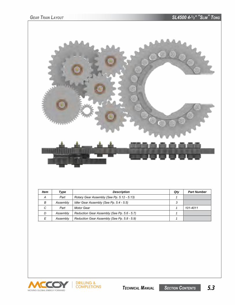
SL4500 4-1/2” “SLim” Tong
SecTion conTenTS 5.3 TechnicaL manuaL
Item Type Description Qty Part NumberA Part RotaryGearAssembly(SeePp.5.12-5.13) 1
B Assembly IdlerGearAssembly(SeePp.5.4-5.5) 3
C Part MotorGear 1 101-4011
D Assembly ReductionGearAssembly(SeePp.5.6-5.7) 1
E Assembly ReductionGearAssembly(SeePp.5.8-5.9) 1
geaR TRain LayouT
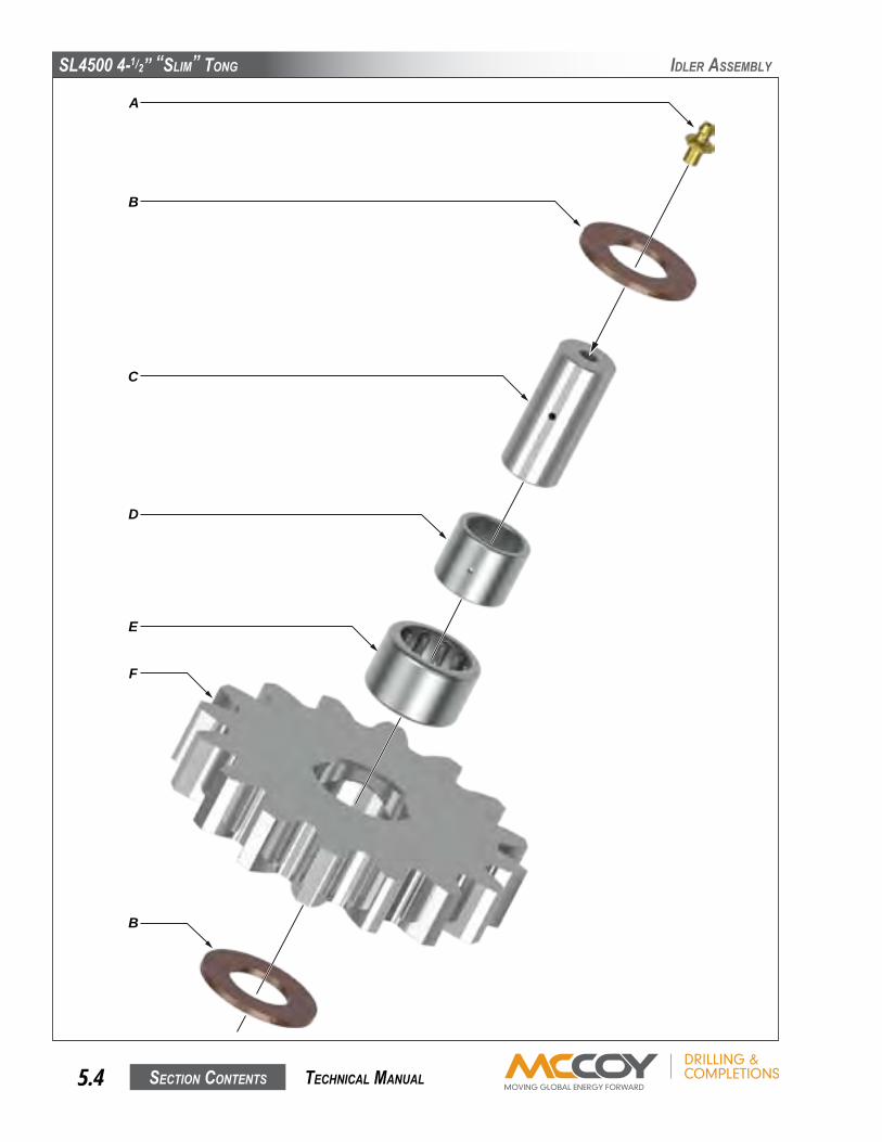
SL4500 4-1/2” “SLim” Tong
SecTion conTenTS5.4 TechnicaL manuaL
iDLeR aSSembLy
A
B
C
D
E
F
B
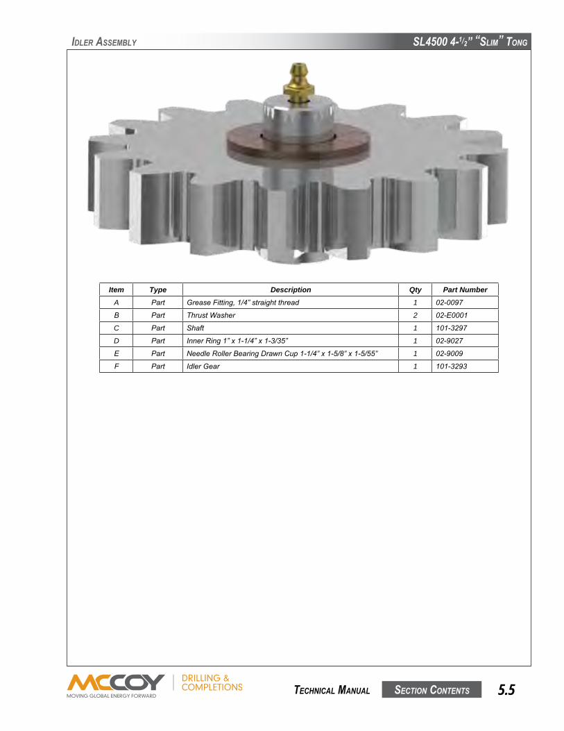
SL4500 4-1/2” “SLim” Tong
SecTion conTenTS 5.5 TechnicaL manuaL
Item Type Description Qty Part NumberA Part GreaseFitting,1/4”straightthread 1 02-0097
B Part ThrustWasher 2 02-E0001
C Part Shaft 1 101-3297
D Part InnerRing1”x1-1/4”x1-3/35” 1 02-9027
E Part NeedleRollerBearingDrawnCup1-1/4”x1-5/8”x1-5/55” 1 02-9009
F Part IdlerGear 1 101-3293
iDLeR aSSembLy

SL4500 4-1/2” “SLim” Tong
SecTion conTenTS5.6 TechnicaL manuaL
ReDucTion geaR aSSembLy (SmaLL)A
B
C
D
E
F
B
D
E
G

SL4500 4-1/2” “SLim” Tong
SecTion conTenTS 5.7 TechnicaL manuaL
ReDucTion geaR aSSembLy (SmaLL)
Item Type Description Qty Part NumberA Part GreaseFitting,1/4”straightthread 1 02-0097
B Part ThrustWasher 2 02-E0001
C Part GearShaft 1 101-3296
D Part InnerRing1”x1-1/4”x1-3/35” 2 02-9027
E Part NeedleRollerBearingDrawnCup1-1/4”x1-5/8”x1-5/55” 2 02-9009
F Part BearingSpacer 1 101-3812
G Part ReductionGear 1 101-3291

SL4500 4-1/2” “SLim” Tong
SecTion conTenTS5.8 TechnicaL manuaL
ReDucTion geaR aSSembLy (LaRge)A
B
C
D
E
F
B
D
E
G
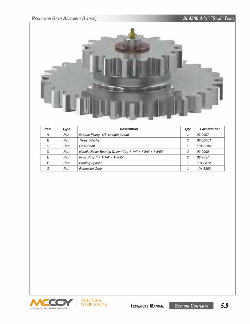
SL4500 4-1/2” “SLim” Tong
SecTion conTenTS 5.9 TechnicaL manuaL
Item Type Description Qty Part NumberA Part GreaseFitting,1/4”straightthread 1 02-0097
B Part ThrustWasher 2 02-E0001
C Part GearShaft 1 101-3296
D Part NeedleRollerBearingDrawnCup1-1/4”x1-5/8”x1-5/55” 2 02-9009
E Part InnerRing1”x1-1/4”x1-3/35” 2 02-9027
F Part BearingSpacer 1 101-3812
G Part ReductionGear 1 101-3292
ReDucTion geaR aSSembLy (LaRge)

SL4500 4-1/2” “SLim” Tong
SecTion conTenTS5.10 TechnicaL manuaL
RoTaRy aSSembLy
K
L
M
N
A
BC
DE
F
G
H
J
P
Q
R
S
T
U

SL4500 4-1/2” “SLim” Tong
SecTion conTenTS 5.11 TechnicaL manuaL
Item Type Description Qty Part NumberA Part 3/8”UNCx2-1/2”HexCapScrew 1 09-1056
B Part 3/8”FlatWasher 1 09-5006
C Part 3/8”UNCx4-1/2”HexCapScrew 4 09-1064
D Part 3/8”X1”UNCShoulderBolt 2 09-1118
E Part 3/8”X1/2”UNCShoulderBolt 2 09-9179
F Part 2-211O-Ring 2 02-0340
G Part TopCagePlate 1 101-3303
H Part CagePlateSpacer 4 101-3333
J Assembly JawDieKit(2-3/8”shown-seePg.2.8) 2
K Assembly RotaryGearAssembly(SeePp.5.12-5.13) 1
L Part BottomCagePlate 1 101-3304
M Part 3/8”Lockwasher 6 09-5106
N Part 3/8”UNCHexNut 4 09-5806
P Part Knob 1 02-0017
Q Part 3/8”UNCStud 1 101-4058
R Part BackingPinBoltSpacer 1 101-4038
S Part BackingPinRetainer 1 101-4040
T Part BackingPin 1 101-4039
U Part 1/4”StraightThreadGreaseFitting 2 02-0097
RoTaRy aSSembLy
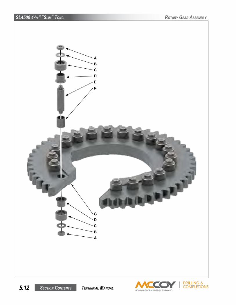
SL4500 4-1/2” “SLim” Tong
SecTion conTenTS5.12 TechnicaL manuaL
RoTaRy geaR aSSembLy
A
G
B
D
C
C
D
B
E
A
F
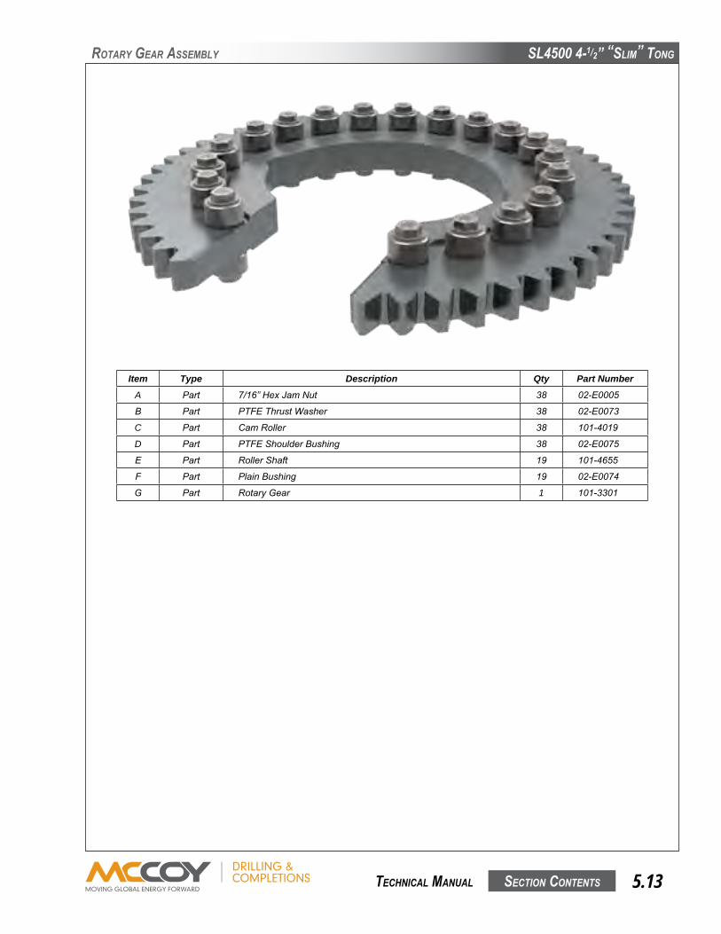
SL4500 4-1/2” “SLim” Tong
SecTion conTenTS 5.13 TechnicaL manuaL
RoTaRy geaR aSSembLy
Item Type Description Qty Part NumberA Part 7/16”HexJamNut 38 02-E0005
B Part PTFEThrustWasher 38 02-E0073
C Part CamRoller 38 101-4019
D Part PTFEShoulderBushing 38 02-E0075
E Part RollerShaft 19 101-4655
F Part PlainBushing 19 02-E0074
G Part RotaryGear 1 101-3301

SL4500 4-1/2” “SLim” Tong
SecTion conTenTS5.14 TechnicaL manuaL
Tong boDy aSSembLy
A B C D D E F G H
K
R
L
J
F
N
P
Q
M
R
ST
QBR
WQ
C
UQRV
Q

SL4500 4-1/2” “SLim” Tong
SecTion conTenTS 5.15 TechnicaL manuaL
Tong boDy aSSembLy
Item Type Description Qty Part NumberA Assembly DoorAssembly(SeePp.5.22-5.23) 1
B Part ExternalSnapRing 4 02-E0004
C Part ShoulderBushing 2 02-E0003
D Part DoorPost 2 101-3306
E Part 3/8”NCx3”HexCapScrew 15 09-1058
F Part 3/8”NCx3-1/2”HexCapScrew 11 09-1060
G Assembly RigidSlingAssembly(SeePp.5.24-5.25) 1
H Assembly MotorAssembly(SeePp.5.18-5.19) 1
J Assembly HydraulicValveAssembly(SeePp.5.16-5.17) 1
K Part 3/8”NCx5”HexCapScrew 4 09-1066
L Part TopPlate 1 101-3361
M Part BodySpacer 2 101-3333
N Part BottomPlate 1 101-3362
P Part GearboxCover 1 101-3317
Q Part 3/8”Lockwasher 44 09-5106
R Part 3/8”NCHexNut 30 09-5806
S Part WearButton 16 101-3389
T Part 1/4”NCx1/2”HexSocketFHCS 16 09-4003
U Part LegPlate(typ.weldedtofrontlegweldment-shownforillustration) 2 101-4034
V Weldment LinedBrakebandWeldment(SeePp.5.20-5.21) 2 101-3393
W Part 3/8”NCx2-1/2”HexBolt 4 09-1056

SL4500 4-1/2” “SLim” Tong
SecTion conTenTS5.16 TechnicaL manuaL
hyDRauLic aSSembLy
A B C D E JGF H
P
K
QRS
L
T
M
MR
LN

SL4500 4-1/2” “SLim” Tong
SecTion conTenTS 5.17 TechnicaL manuaL
Item Type Description Qty Part NumberA Part 1/4”NCx3/4”HexCapScrew 2 09-1005
B Part 1/2”NCThinNylockNut 3 09-5610S
C Part 1/2”NarrowWasher 3 09-5119
D Part CableGuideHolder 1 101-4236
Part CableGuideHolderRetainer 2 02-E0025
E Part SafetyDoorValve 1 08-0337
Part 1/4”NPT90DegreeFitting 6 08-0284
F Weldment ValveMount 1 101-4101
G Weldment TorqueGaugeMount 1 101-4403
H Assembly DVA35ValveAssembly 1 VARIES
J Part 1/2”NCx4-1/2”HexCapScrew 3 09-1184
K Part HITCHPIN.148X2.938:1 1
L Part 1/4”NarrowWasher 4 09-1119
M Part 1/4”NCNylockNut 4 09-5701
N Part Valve 1 10-9024A
P Part 1/4”NCx2”HexCapScrew 2 09-1015
Q Part 3/8”NCx1”HexCapScrew 4 09-1046
R Part 3/8”Lockwasher 6 09-5106
S Part 3/8”NCx2”HexCapScrew 4 09-1054
T Part ValveBody 1 08-1327
hyDRauLic aSSembLy

SL4500 4-1/2” “SLim” Tong
SecTion conTenTS5.18 TechnicaL manuaL
moToR aSSembLy
G
H
J
A B DC E AF
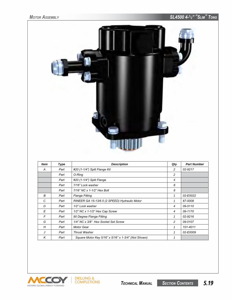
SL4500 4-1/2” “SLim” Tong
SecTion conTenTS 5.19 TechnicaL manuaL
moToR aSSembLy
Item Type Description Qty Part NumberA Part #20(1-1/4”)SplitFlangeKit 2 02-9217
Part O-Ring 2
Part #20(1-1/4”)SplitFlange 4
Part 7/16”Lockwasher 8
Part 7/16”NCx1-1/2”HexBolt 8
B Part FlangeFitting 1 02-E0022
C Part RINEERGA15-13/6.5(2SPEED)HydraulicMotor 1 87-0008
D Part 1/2”Lockwasher 4 09-5110
E Part 1/2”NCx1-1/2”HexCapScrew 4 09-1170
F Part 90DegreeFlangeFitting 1 02-9216
G Part 1/4”NCx3/8”HexSocketSetScrew 2 09-0107
H Part MotorGear 1 101-4011
J Part ThrustWasher 1 02-E0009
K Part SquareMotorKey5/16”x5/16”x1-3/4”(NotShown) 1

SL4500 4-1/2” “SLim” Tong
SecTion conTenTS5.20 TechnicaL manuaL
bRake banDS
A B C D
GF
E

SL4500 4-1/2” “SLim” Tong
SecTion conTenTS 5.21 TechnicaL manuaL
bRake banDS
Item Type Description Qty Part NumberA Part 3/8”NCHexNut 1 09-5806
B Part 3/8”Lockwasher 1 09-5106
C Weldment LinedBrakebandWeldment 2 101-3393
D Assembly BellevilleWasherAssembly 8 101-3272
E Part 3/8”NCx3-1/4”HexCapScrew 1 09-1059
F Part BrakebandRetainer 1 101-3975
G Part 3/8”x5/8”ShoulderBolt 2 02-E0045
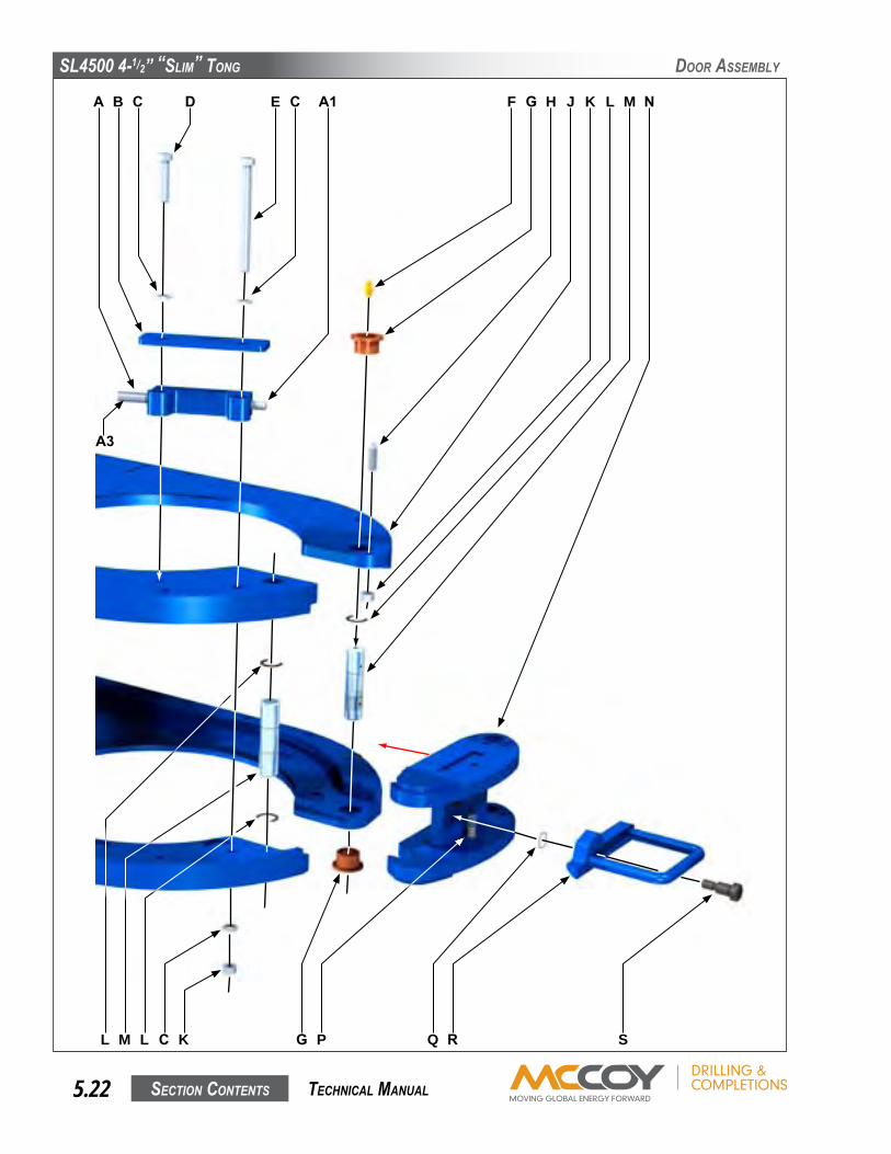
SL4500 4-1/2” “SLim” Tong
SecTion conTenTS5.22 TechnicaL manuaL
DooR aSSembLy
A B C D E HF G LJ K
L M L C K G P Q R S
M NC A1
A3

SL4500 4-1/2” “SLim” Tong
SecTion conTenTS 5.23 TechnicaL manuaL
DooR aSSembLy
Item Type Description Qty Part NumberA Part CableGuideHolder 1 101-4235
A1 Part SafetyDoorPlunger 1 101-4360
A2 Part Push-PullControlCable 1 02-E0026
A2 Part 7/16”UNFHexJamNut 1 09-5508
B Part CableGuideGuard 1 101-4237
C Part 3/8”Lockwasher 2 09-5106
D Part 3/8”NCx1-3/4”HexCapScrew 1 09-1557
E Part 3/8”NCx4-1/2”HexCapScrew 1 09-1064
F Part 1/4”StraightThreadGreaseFitting 1 02-0097
G Part ShoulderBushing 2 02-E0003
H Part Detentc/wbutton 1 02-0899
J Part TopPlate(shownforillustration) 1 101-3361
K Part 3/8”NCHexNut 2 09-5806
L Part ExternalSnapRing 4 02-E0004
M Part DoorPost 2 101-3306
N Weldment DoorWeldment 1 101-4300
P Part CompressionSpring 1 C0460-0050-1125
Q Part WaveSpring 1 02-9267
R Part LatchWeldment 1 101-3530
S Part 3/8”x3/4”ShoulderBolt 1 09-0223

SL4500 4-1/2” “SLim” Tong
SecTion conTenTS5.24 TechnicaL manuaL
RigiD SLing aSSembLy
A
BCD
G
E
F
HJ
KL

SL4500 4-1/2” “SLim” Tong
SecTion conTenTS 5.25 TechnicaL manuaL
Item Type Description Qty Part NumberA Weldment RigidSlingWeldment 1 101-4137
B Part 0.148”x2.938”HitchPin 2 02-0028
C Part 3/4”NarrowWasher 4 09-5013
D Part RigidSlingPin 2 02-E0008
E Part 3/8”NCx3-1/2”HexCapScrew 8 09-1060
F Part RigidSlingLevelingBolt 4 02-E0038
G Part 1/2”NCHexNut 4 09-9124
H Part RigidSlingLiftingLug 4 101-3337
J Part RigidSlingAdjustmentBoltSpacer 4 101-4138
K Part 3/8”Lockwasher 8 09-5106
L Part 3/8”NCHexNut 8 09-5806
RigiD SLing aSSembLy
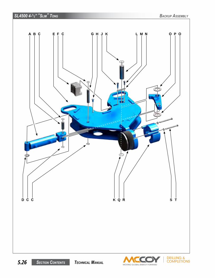
SL4500 4-1/2” “SLim” Tong
SecTion conTenTS5.26 TechnicaL manuaL
backuP aSSembLy
A
D K
E L OB
C Q S
F M PG JC
C R T
C N OH K

SL4500 4-1/2” “SLim” Tong
SecTion conTenTS 5.27 TechnicaL manuaL
backuP aSSembLy
Item Type Description Qty Part NumberA Assembly HydraulicCylinderAssembly 1 101-4336
B Part CylinderPin 1 101-3676
C Part ExternalRetainingRing 4 02-E0036
D Part 3/4”NarrowFlatwasher 1 09-5013
E Weldment BackupBodyWeldment 1 101-4337
F Assembly JawDieKit(2-3/8”shown-seePg.2.13) 2
G Part CylinderPin 1 101-4329
H Part JawRetainerBolt 2 101-4264
J Part 3/8”x1”UNCSocketHeadShoulderScrew 1 09-1118
K Part ExternalRetainingRing 2 02-E0037
L Part LeverPin 1 101-4330
M Part 3/8”x1/2”UNCSocketHeadShoulderScrew 1 09-9179
N Part 2-213O-Ring 1 02-0347
O Part 1-1/4”PlainNarrowWasher 2 02-E0043
P Part CamArm 1 101-3672
Q Part CompressionLoadCell,CC-108 1 10-0008C
R Weldment LoadCellHolderWeldment 1 101-4340
S Part 5/16”NarrowFlatwasher 2 02-E0044
T Part 5/16”NCx4”HexCapScrew 2 09-1024

SL4500 4-1/2” “SLim” Tong
SecTion conTenTS5.28 TechnicaL manuaL
ReaR Leg aSSembLy
A B C D
F
E
A
G
H
J

SL4500 4-1/2” “SLim” Tong
SecTion conTenTS 5.29 TechnicaL manuaL
Item Type Description Qty PartNumber
A Part 3/4”Lockwasher 4 09-5118
B Part 3/4”NCx3-1/2”HexCapScrew 1 09-1300
C Part RearLegSpring 2 997-13
D Weldment BackupSupportPlate 2 101-3885
E Part 3/4”NCx5”HexCapScrew 1 09-1306
F Weldment RearLegWeldment 1 101-3883
G Part 3/4”HexNut 2 09-5818
H Part 0.093”x1.125”HitchPin 2 02-E0046
J Part SupportRod 1 101-3891
ReaR Leg aSSembLy

SL4500 4-1/2” “SLim” Tong
SecTion conTenTS5.30 TechnicaL manuaL
fRonT Leg aSSembLy
A
BCD
H
EFGD
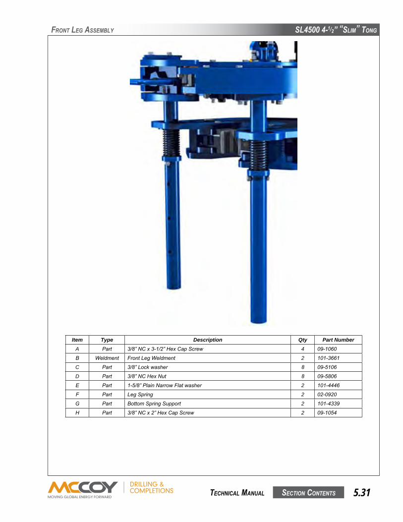
SL4500 4-1/2” “SLim” Tong
SecTion conTenTS 5.31 TechnicaL manuaL
Item Type Description Qty Part NumberA Part 3/8”NCx3-1/2”HexCapScrew 4 09-1060
B Weldment FrontLegWeldment 2 101-3661
C Part 3/8”Lockwasher 8 09-5106
D Part 3/8”NCHexNut 8 09-5806
E Part 1-5/8”PlainNarrowFlatwasher 2 101-4446
F Part LegSpring 2 02-0920
G Part BottomSpringSupport 2 101-4339
H Part 3/8”NCx2”HexCapScrew 2 09-1054
fRonT Leg aSSembLy

This page intentionallyleft blank
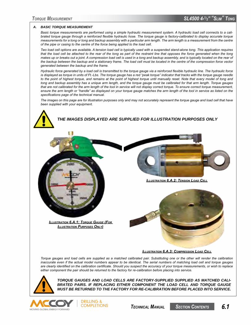
SL4500 4-1/2” “SLim” Tong
SecTion conTenTS 6.1 TechnicaL manuaL
ToRque meaSuRemenT
A. BASIC TORQUE MEASUREMENT Basictorquemeasurementsareperformedusingasimplehydraulicmeasurementsystem.Ahydraulicloadcellconnectstoacali-bratedtorquegaugethroughareinforcedflexiblehydraulichose.Thetorquegaugeisfactory-calibratedtodisplayaccuratetorquemeasurementsforatongortongandbackupassemblywithaparticulararmlength.Thearmlengthisameasurementfromthecentreofthepipeorcasingtothecentreoftheforcebeingappliedtotheloadcell.
Twoloadcelloptionsareavailable.Atensionloadcellistypicallyusedwithasuspendedstand-alonetong.Thisapplicationrequiresthat the loadcellbeattachedto therearof the tongaspartof therestraint line thatopposesthe forcegeneratedwhenthe tongmakesuporbreaksoutajoint.Acompressionloadcellisusedinatongandbackupassembly,andistypicallylocatedontherearofthebackupbetweenthebackupandastationaryframe.Theloadcellmustbelocatedinthecentreofthecompressionforcevectorgeneratedbetweenthebackupandtheframe.
Hydraulicforcegeneratedbyaloadcellistransmittedtothetorquegaugeviaareinforcedflexiblehydraulicline.ThehydraulicforceisdisplayedastorqueinunitsofFt.-Lbs.Thetorquegaugehasared“peaktorque”indicatorthattrackswiththetorquegaugeneedleto thepointofhighest torque,andremainsat thepointofhighest torqueuntilmanuallyreset.Note thateverymodelof tongandtongandbackupassemblyhasauniquearmlength,andthetorquegaugemustbecalibratedforthatarmlength.Torquegaugesthatarenotcalibratedforthearmlengthofthetoolinservicewillnotdisplaycorrecttorque.Toensurecorrecttorquemeasurement,ensurethearmlengthor“handle”asdisplayedonyourtorquegaugematchesthearmlengthofthetoolinserviceaslistedonthespecificationspageofthetechnicalmanual.
Theimagesonthispageareforillustrationpurposesonlyandmaynotaccuratelyrepresentthetorquegaugeandloadcellthathavebeensuppliedwithyourequipment.
IllustratIon 6.a.1: torque gauge (for IllustratIon purposes only)
IllustratIon 6.a.3: compressIon loaD cell
THE IMAGES DISPLAYED ARE SUPPLIED FOR ILLUSTRATION PURPOSES ONLY
TORQUE GAUGES AND LOAD CELLS ARE FACTORY-SUPPLIED SUPPLIED AS MATCHED CALI-BRATED PAIRS. IF REPLACING EITHER COMPONENT THE LOAD CELL AND TORQUE GAUGE MUST BE RETURNED TO THE FACTORY FOR RE-CALIBRATION BEFORE PLACED INTO SERVICE.
Torquegaugesand loadcellsaresuppliedasamatchedcalibratedpair.Substitutingoneor theotherwill render thecalibrationinaccurateeven if theactualmodelnumbersappear tobe identical.Theserialnumbersofmatching loadcellandtorquegaugesareclearlyidentifiedonthecalibrationcertificate.Shouldyoususpecttheaccuracyofyourtorquemeasurements,orwishtoreplaceeithercomponentthepairshouldbereturnedtothefactoryforre-calibrationbeforeplacingintoservice.
IllustratIon 6.a.2: tensIon loaD cell

SL4500 4-1/2” “SLim” Tong
SecTion conTenTS6.2 TechnicaL manuaL
ToRque meaSuRemenT
Item Type Description Qty Part NumberAssembly 24”Arm-8000Lbs.-Ft.TorqueGauge/TensionLoadCellAssembly 1 10-0025T
1 Part 24”Arm8,000Lbs.-FtTorqueGauge 1 10-0025G
2 Part TensionLoadCell,4.08in2 1 10-0008T
3 Part HydraulicHose 1 02-0069
Item Type Description Qty Part NumberAssembly 18”Arm-4K/8.5KTorqueGauge/Comp.LoadCellAssembly 1 10-0025C
1 Part 18”Arm8,500Lbs.-FtTorqueGauge 1 10-0025G
2 Part CompressionLoadCell,8in2 1 10-0008C
3 Part HydraulicHose 1 02-0069
THE TORQUE GAUGE USED IS FULLY DEPENDANT UPON THE ARM LENGTH AND TORQUE RANGE OF THE EQUIPMENT IN USE. THE PART NUMBERS LISTED IN THE FOLLOWING TABLES ARE CORRECT FOR ACCURATELY MEASURING TORQUE USING THE EQUIPMENT FOR WHICH THIS MANUAL IS SUPPLIED.
BASIC TORQUE MEASUREMENT (Continued:)Theimagesontheprecedingpageareforillustrationpurposesonlyandmaynotaccuratelyrepresentthetorquegaugeandloadcellthathavebeensuppliedwithyourequipment.Pleasenotethatthepartslistedinthefollowingtablearecorrectforaccuratetorquemeasurementwhileusingtheequipmentforwhichthismanualissupplied.
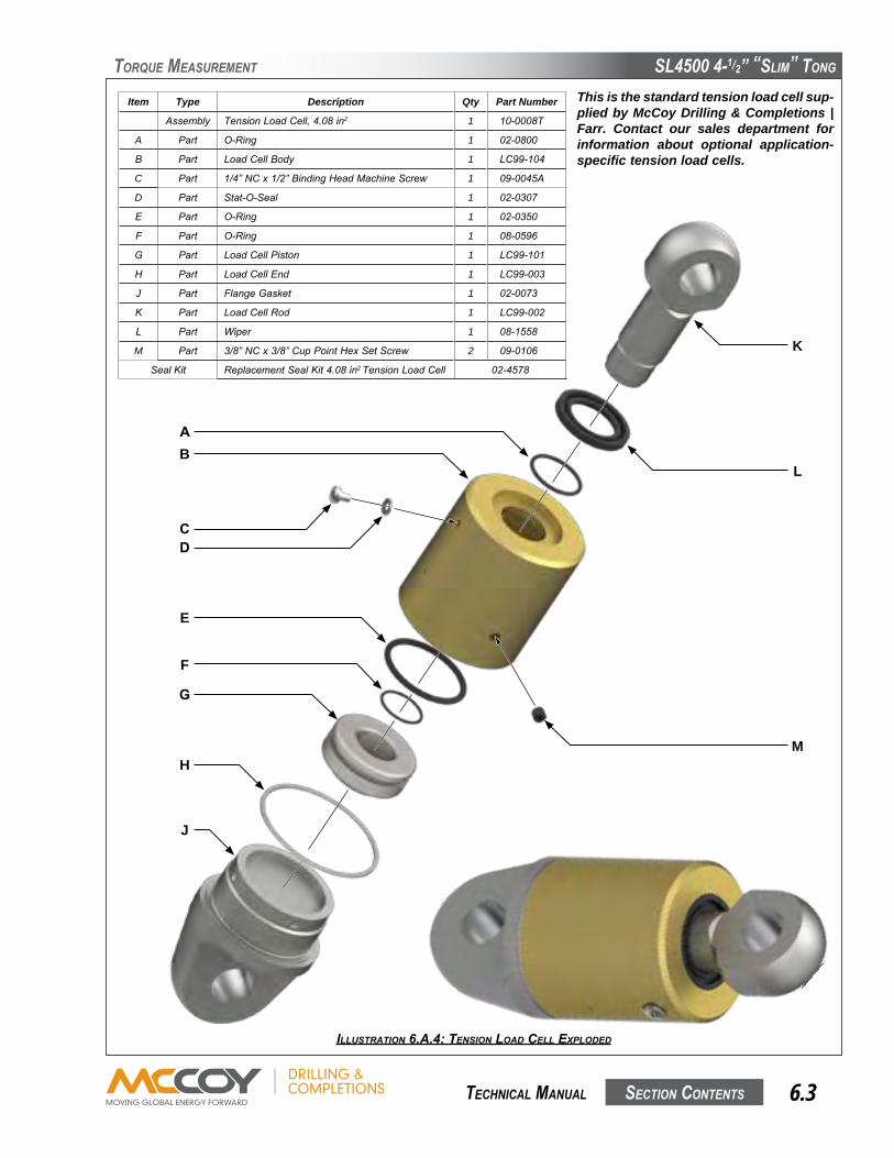
SL4500 4-1/2” “SLim” Tong
SecTion conTenTS 6.3 TechnicaL manuaL
ToRque meaSuRemenT
Item Type Description Qty Part Number
Assembly TensionLoadCell,4.08in2 1 10-0008T
A Part O-Ring 1 02-0800
B Part LoadCellBody 1 LC99-104
C Part 1/4”NCx1/2”BindingHeadMachineScrew 1 09-0045A
D Part Stat-O-Seal 1 02-0307
E Part O-Ring 1 02-0350
F Part O-Ring 1 08-0596
G Part LoadCellPiston 1 LC99-101
H Part LoadCellEnd 1 LC99-003
J Part FlangeGasket 1 02-0073
K Part LoadCellRod 1 LC99-002
L Part Wiper 1 08-1558
M Part 3/8”NCx3/8”CupPointHexSetScrew 2 09-0106
SealKit ReplacementSealKit4.08in2TensionLoadCell 02-4578
This is the standard tension load cell sup-plied by McCoy Drilling & Completions | Farr. Contact our sales department for information about optional application-specific tension load cells.
IllustratIon 6.a.4: tensIon loaD cell exploDeD
AB
CD
E
F
G
H
J
K
L
M
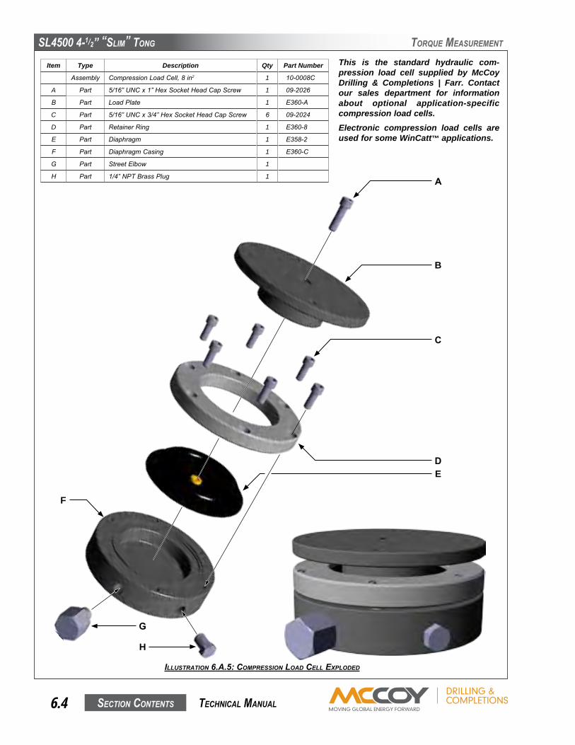
SL4500 4-1/2” “SLim” Tong
SecTion conTenTS6.4 TechnicaL manuaL
ToRque meaSuRemenT
Item Type Description Qty Part Number
Assembly CompressionLoadCell,8in2 1 10-0008C
A Part 5/16”UNCx1”HexSocketHeadCapScrew 1 09-2026
B Part LoadPlate 1 E360-A
C Part 5/16”UNCx3/4”HexSocketHeadCapScrew 6 09-2024
D Part RetainerRing 1 E360-8
E Part Diaphragm 1 E358-2
F Part DiaphragmCasing 1 E360-C
G Part StreetElbow 1
H Part 1/4”NPTBrassPlug 1
This is the standard hydraulic com-pression load cell supplied by McCoy Drilling & Completions | Farr. Contact our sales department for information about optional application-specific compression load cells.Electronic compression load cells are used for some WinCatt™ applications.
IllustratIon 6.a.5: compressIon loaD cell exploDeD
A
B
C
DE
F
G
H

SL4500 4-1/2” “SLim” Tong
SecTion conTenTS 6.5 TechnicaL manuaL
ToRque meaSuRemenT
Item Type Description Qty Part Number
Assembly StandardTurnCounterEncoderMount 1 60-0001
A Part 6-32x3/8”HexSocketHeadSetScrew 4
B Part HelicalFlexibleEncoderShaftCoupling 1 60-0130N
C Part InternalRetainerRing 2 1376-13
D Part Bearing 2 1376-05
E Part EncoderHousing 1 1392-104A
F Part InternalRetainerRing 1 02-0436
G Part EncoderShaft 1 1392-103A-01
H Part EncoderGear 1 01-0320A-M
J Part 10-24x1-1/4”HexSocketHeadSetScrew 1
IllustratIon 6.a.6: turn counter encoDer mount exploDeD
2.74”2.75”
AB
C
D
E
D
C
F
G
H
J

SL4500 4-1/2” “SLim” Tong
SecTion conTenTS6.6 TechnicaL manuaL
ToRque meaSuRemenT
B. TROUBLESHOOTINGUndernormaloperatingconditions,andwithpropermaintenance,thetorquegaugeandloadcellsystemaredesignedtogivelastingtrouble-freeperformance.Faultyindicationonthegaugewillveryoftendefineafaultwithinthegauge.
1. Symptom: No indication on gauge.
PossibleProblem: Obstructioninhydraulichose. Solutions: Checkhydraulichoseforkinks. Replacehydraulichose.
PossibleProblem: Lossofhydraulicfluid. Solution: Rechargehydraulicfluid(seeSection6.C).NOTE:Ensureanybreachesinthehydraulicsystem betweentheloadcellandtorquegaugearerepairedtopreventfurtherfluidloss.
PossibleProblem: Internalmechanismoftorquegaugeisdamaged. Solution: Replacegauge.
2. Symptom: Gauge indication unexpectedly high.
PossibleProblem: Excessivehydraulicfluid. Solutions: Completelydrainhydraulicfluidfromtorquegauge/loadcellsystem.Rechargefollowingthe procedureinSection6.C.
PossibleProblem: Internalmechanismofgaugeisdamaged. Solution: Replacegauge.
PossibleProblem: Incorrecttorquegaugeinuse(notpartoftheoriginaltorquegauge/loadcellpair). Solution: Replacegaugewithgaugeproperlycalibratedfortheloadcellinservice.
3. Symptom: Gauge indication unexpectedly low
PossibleProblem: Insufficienthydraulicfluid. Solution: Rechargehydraulicfluid(seeSection6.C).NOTE:Ensureanybreachesinthehydraulicsystem betweentheloadcellandtorquegaugearerepairedtopreventfurtherfluidloss.
PossibleProblem: Obstructioninhydraulichose. Solutions: Checkhydraulichoseforkinks. Replacehydraulichose.
PossibleProblem: Snublinenotatright-angletotonghandle. Solution: Checkangleofsnublineandcorrectifnecessary.
PossibleProblem: Internalmechanismofgaugeisdamaged. Solution: Replacegauge.
PossibleProblem: Incorrecttorquegaugeinuse(notpartoftheoriginaltorquegauge/loadcellpair). Solution: Replacegaugewithgaugeproperlycalibratedfortheloadcellinservice.
4. Symptom: Gauge indication is erratic or sluggish
PossibleProblem: Insufficienthydraulicfluidintorquemeasurementsection. Solution: Rechargehydraulicfluid(seeSection6.C).NOTE:Ensureanybreachesinthehydraulicsystem betweentheloadcellandtorquegaugearerepairedtopreventfurtherfluidloss.
PossibleProblem: Lossofdampingfluidintorquegauge. Solution: Topuporrefilldampingfluid(NOTE:Ensureleakagepointsingaugeareidentifiedandrepaired topreventfurtherlossofdampingfluid).
PossibleProblem: Airbubblesinhydraulicfluidinthetorquemeasurementsystem. Solution: Bleedairfromloadcellandtorquegaugeandtopupfluid(ifnecessary)asperSection6.C.
PossibleProblem: Internalmechanismofgaugeisdamaged. Solution: Replacegauge.
IF TROUBLESHOOTING REVEALS THAT THERE IS INSUFFICIENT FLUID IN THE SYSTEM,BEFORE RECHARGING, CHECK THAT ALL SYSTEM COMPONENTS ARE FREE FROMDAMAGE.THISWILLENSURETHATFLUIDLOSSWILLNOTCONTINUEAFTERRELOADING
SL4500 4-1/2” “SLim” Tong
SecTion conTenTS 6.7 TechnicaL manuaL
ToRque meaSuRemenT
C. PERIODIC INSPECTION AND MAINTENANCE1. Inspection
Thetorquemeasurementsystemsuppliedwithyourequipmentisdesignedandbuilttoprovideyearsoftrouble-freeservicewithminimummaintenance.Periodicinspectionsoftheloadcell,hydrauliclinesandfittingsarerecommendedinordertokeepthesystemintopoperatingcondition.Athoroughinspectionshouldbemadeateachrig-up.
2. Fluid RechargeRechargehydraulicsystemwithW15/16fluidthroughthecheckvalveonthetorqueindicatinggauge.Rechargingmustonlybeperformedwhenthereisnoloadontheloadcell.Refertotheillustrationsonpages6.3&6.4forguidanceifrequired.a. Placethetorqueindicatinggaugehigherthantheloadcell.Removethebrass1/4”capfromthefittingonthecheckvalve
onthetopofthegauge.b. Connectthehandpumptothecheckvalvefitting.c. Elevatetheloadcellsoitishigherthanthetorquegaugeandhandpump.
MAINTAIN GREATER-THAN HALF FULL FLUID LEVEL IN THE HAND PUMP BOWL TO AVOID PUMPING AIR INTO THE SYSTEM. DO NOT ALLOW THE LEVEL TO FALL BELOW ONE-HALF FULL
UN-CONTAINED SPILLAGE OF THE HYDRAULIC FLUID IN THIS SYSTEM MAY CONTRAVENE GOVERNMENTAL ENVIRONMENTAL REGULATIONS, OR THE ENVIRONMENTAL REGULATIONS AND POLICIES OF YOUR COMPANY. MCCOY DRILLING & COMPLETIONS HIGHLY RECOMMENDS PLACING YOUR LOAD CELL IN A CONTAINMENT BASIN BEFORE PROCEEDING WITH THE BLEEDING & REFILLING PROCESS.
d. FillhandpumpbowlwithW15/16hydraulicfluid.
e. RemovetheventplugscrewandStat-O-Seal(ItemsCandDonIllustration6.A.4,oritemHonIllustration6.A.5)toallowtrappedairtoescape.
f. Pumpfluidintothesystemuntilnomoreairisseenescapingfromtheventport.g. ReplacetheventplugscrewandStat-O-Sealandtightensecurely.h. Removeloadcellfromcontainmentvesselandwipeclean.Reclaimthehydraulicfluid(ifitisclean)ordisposeofallwaste
materialsaccordingtogovernmentaloryourcompany’sproscribedenvironmentalprotectionregulations.i. Disconnectthehandpumpfromthetorquegauge.j. Replacethebrasscaponthetorquegaugecheckvalvefitting.
3. Repair And CalibrationLoadcellandindicatorgaugeshouldbereturnedtoauthorizedrepairfacilityforanyrepairsorcalibrationrequired.

This page intentionallyleft blank

SL4500 4-1/2” “SLim” Tong
SecTion conTenTS 7.1 TechnicaL manuaL
Section 7: Hydraulic Component InformationThe manufacturer information contained in this section has been obtained from publicly available web sites and has been provided for information purposes only. Farr Canada Corp. does not guarantee the accuracy of the infor-mation contained in this section. All original copyrights claimed by the manufacturer(s) apply.

This page intentionallyleft blank
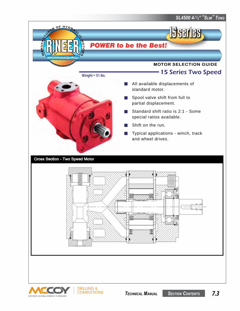
SL4500 4-1/2” “SLim” Tong
SecTion conTenTS 7.3 TechnicaL manuaL
Technical Information - Two Speed Motor
DISPLACEMENT CHANGEWhen a motor is shifted from full to partial displacement themotor is changed to 50%, 35%, or 28% of its originaldisplacement depending on its shift ratio.
STANDARD SHIFT RATIOThe standard 15 Series displacements of 15, 13, 9.5, 8, 7,and 6 CID are available in the 15 Series Two Speed with ashift ratio of 2:1. For example, a 15 CID motor shifted topartial displacement becomes a 7.5 CID motor.
SPECIAL SHIFT RATIOSThere are two special displacements available in the 15Series Two Speed which offer higher shift ratios, the 10.5and the 11.5 CID. The 10.5 CID motor has a shift ratio of3.5:1, which when shifted becomes a 3 CID motor. The 11.5CID motor has a shift ratio of 2.875:1, which when shiftedbecomes a 4 CID motor.
SHIFTING METHODSelecting between full and partial displacement isaccomplished by shifting the two-position spool valveincorporated in the motor. Motors are available in eithersingle or double pilot configurations.
SINGLE PILOTSingle pilot motors require a pilot line to be connected to port"C". When port "C" is pressurized the spool shifts the motorto partial displacement. When port "C" is vented to tank, aninternal spring shifts the spool, returning the motor to fulldisplacement.
DOUBLE PILOTDouble pilot motors require two pilot lines. One line isconnected to port "C" while the other line is connected toport "D". The motor is in full displacement when port "D" ispressurized and port "C" is vented to tank. The motor is inpartial displacement when port "C" is pressurized and port"D" is vented to tank.
OPEN DURING CROSSOVER SPOOLSOpen during crossover spools allow port "A" to be directlyconnected to port "B" when the spool is shifting between fulland partial displacement. Motors with -62 or -65 designationsare open during crossover.WARNING! IN SOME WINCH APPLICATIONS, OPENDURING CROSSOVER SPOOLS (-62 or -65) ARE NOTRECOMMMENDED.
CLOSED DURING CROSSOVER SPOOLSClosed during crossover spools do not allow port "A" to bedirectly connected to port "B" when the spool is shiftingbetween full and partial displacement. Motors with -63 or -67designations are closed during crossover. These motorscontain an internal factory preset relief valve. This valveprotects the motor during shifting only and is not a systemrelief valve.
PILOT PRESSUREA minimum of 100 PSI over case drain pressure is required toshift the spool. The maximum allowable pressure to port "C" or"D" is 3,500 PSI.
SHIFT ON THE RUNThe 15 Series Two Speed Motor may be shifted on the runwhile loaded or unloaded.
MAXIMUM SPEEDMaximum rated speed is the same for either full or partialdisplacement as stated in the performance data.
CASE DRAIN AND CROSS PORT LEAKAGEThe combined case drain and cross port leakage of the 15Series Two Speed Motor is approximately 1 GPM per 1,000PSI. This will vary with the oil viscosity.
OTHER INFORMATIONAll other information as specified under Techinal Informationalso applies to the 15 Series Two Speed Motor. (See page 5)
Cross Section - Two Speed Motor
Eight fixed displacement motorsranging from 6 in3 to 15 in3.Starting and stall torques equalto 90-94% of theoretical torque.Speed to 2,000 RPM continuous.Up to 75 HP continuous.Conforms to SAE 'C' mountingspecification.Weighs 43 lbs.
Features of the 15 Series Standard Motor:Standard Motor - 3000 PSI (Code 61)
MOTOR SELECTION GUIDE
POWER to be the Best!
CROSS SECTION
Made in USA PUBLICATION DS151005 8/03
HYDRAULICS, INC.HYDRAULICS, INC.
R
MA
NU
FA
CT
U
RER OF HYDRAULICM
OT
OR
S
15 Series Wheel MotorWeight = 58 lbs.
Tapered roller bearings for radialand axial loading.
Available in single or two speed.
Eight displacements ranging from6 in3 to 15 in3.
Envelope dimensions remain thesame regardless of displacement.
Starting and stall torques equalto 90-94% theoretical torque.
Speed to 2,000 RPM continuous.
15 Series Two SpeedWeight = 51 lbs.
All available displacements ofstandard motor.
Spool valve shift from full topartial displacement.
Standard shift ratio is 2:1 - Somespecial ratios available.
Shift on the run.
Typical applications - winch, trackand wheel drives.
15 Series RetractableWeight = 61 lbs.
Shaft easily retracted from drivenmechanism while allowing full torquethrough SAE C mount.
Manual rear knob for fast, easydisengagement.
Spring loaded shaft engages easilyback into mechanism.
Shaft held in retracted position by usersupplied spacer between knob and rearhousing.
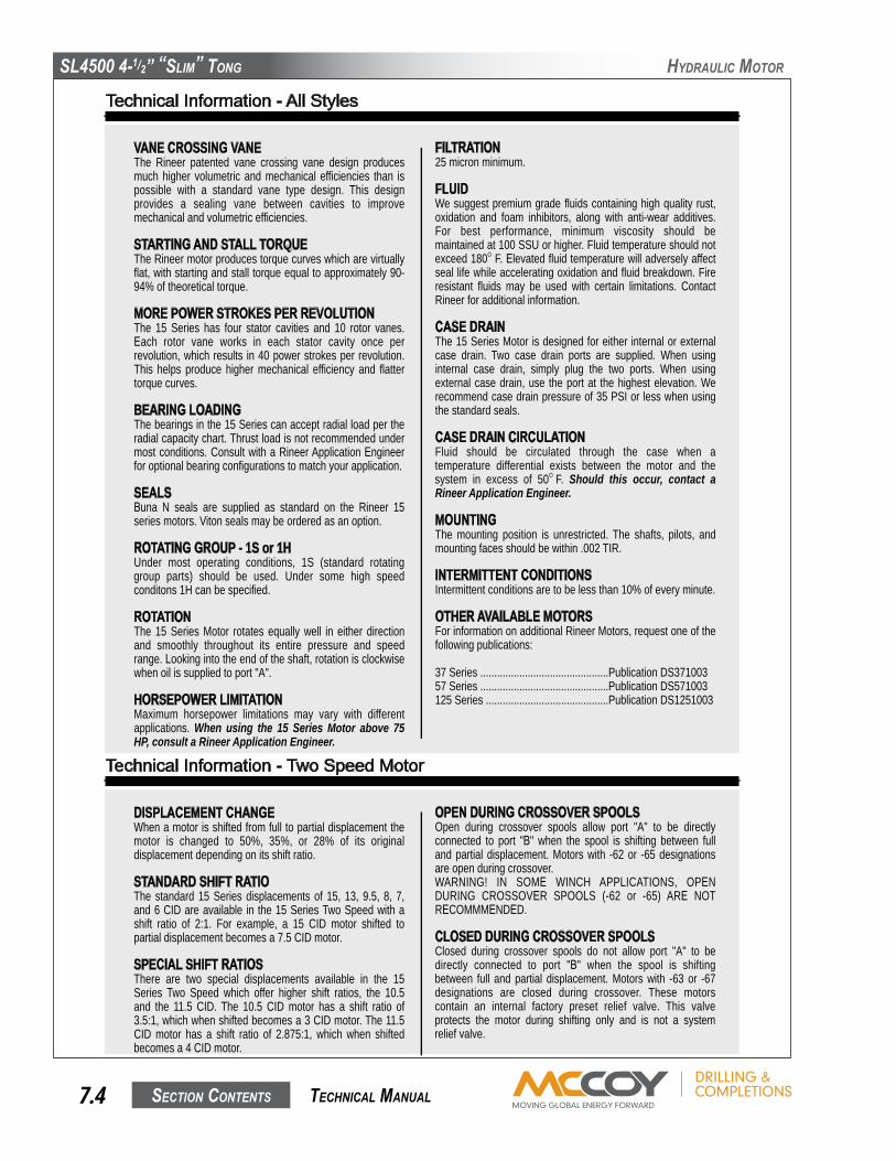
SL4500 4-1/2” “SLim” Tong
SecTion conTenTS7.4 TechnicaL manuaL
hyDRauLic moToR
Technical Information - All Styles
VANE CROSSING VANEThe Rineer patented vane crossing vane design producesmuch higher volumetric and mechanical efficiencies than ispossible with a standard vane type design. This designprovides a sealing vane between cavities to improvemechanical and volumetric efficiencies.
STARTING AND STALL TORQUEThe Rineer motor produces torque curves which are virtuallyflat, with starting and stall torque equal to approximately 90-94% of theoretical torque.
MORE POWER STROKES PER REVOLUTIONThe 15 Series has four stator cavities and 10 rotor vanes.Each rotor vane works in each stator cavity once perrevolution, which results in 40 power strokes per revolution.This helps produce higher mechanical efficiency and flattertorque curves.
BEARING LOADINGThe bearings in the 15 Series can accept radial load per theradial capacity chart. Thrust load is not recommended undermost conditions. Consult with a Rineer Application Engineerfor optional bearing configurations to match your application.
SEALSBuna N seals are supplied as standard on the Rineer 15series motors. Viton seals may be ordered as an option.
ROTATING GROUP - 1S or 1HUnder most operating conditions, 1S (standard rotatinggroup parts) should be used. Under some high speedconditons 1H can be specified.
ROTATIONThe 15 Series Motor rotates equally well in either directionand smoothly throughout its entire pressure and speedrange. Looking into the end of the shaft, rotation is clockwisewhen oil is supplied to port "A".
HORSEPOWER LIMITATIONMaximum horsepower limitations may vary with differentapplications. When using the 15 Series Motor above 75HP, consult a Rineer Application Engineer.
FILTRATION25 micron minimum.
FLUIDWe suggest premium grade fluids containing high quality rust,oxidation and foam inhibitors, along with anti-wear additives.For best performance, minimum viscosity should bemaintained at 100 SSU or higher. Fluid temperature should notexceed 180O F. Elevated fluid temperature will adversely affectseal life while accelerating oxidation and fluid breakdown. Fireresistant fluids may be used with certain limitations. ContactRineer for additional information.
CASE DRAINThe 15 Series Motor is designed for either internal or externalcase drain. Two case drain ports are supplied. When usinginternal case drain, simply plug the two ports. When usingexternal case drain, use the port at the highest elevation. Werecommend case drain pressure of 35 PSI or less when usingthe standard seals.
CASE DRAIN CIRCULATIONFluid should be circulated through the case when atemperature differential exists between the motor and thesystem in excess of 50O F. Should this occur, contact aRineer Application Engineer.
MOUNTINGThe mounting position is unrestricted. The shafts, pilots, andmounting faces should be within .002 TIR.
INTERMITTENT CONDITIONSIntermittent conditions are to be less than 10% of every minute.
OTHER AVAILABLE MOTORSFor information on additional Rineer Motors, request one of thefollowing publications:
37 Series ..............................................Publication DS37100357 Series ..............................................Publication DS571003125 Series ............................................Publication DS1251003
Technical Information - Retractable Shaft Motor
RETRACTING THE SHAFTThe shaft is spring loaded into the engaged position. Pullingon the knob attached to the shaft at the rear of the motor willmove the shaft 1.25 inches into the motor.CAUTION: Retracting the shaft must be done when themotor and driven mechanism are not in operation andare unloaded.
RETAINING SHAFT IN RETRACTED POSITIONThe shaft is retained in the retracted position by inserting a2.0 inch wide spacer between the rear housing and the knobattached to the shaft. Depending on the application andmounting position of the motor, the spacer design may vary.Spacers are not supplied with the motor.
RE-ENGAGING THE SHAFTThis is accomplished by releasing the shaft, then rotating itclockwise until the splines of the shaft line up and engage thesplines of the driven mechanism.CAUTION: Re-engaging the shaft must be done when themotor and driven mechanism are not in operation and areunloaded.
BEARING LOADINGThe 15 series Retractable is not suitable for applications whichrequire radial or axial loading of the shaft.
MOUNTINGThe mounting position is unrestricted. CAUTION: The shaftextension and knob at the rear of the motor rotates whenthe motor is in operation.
Technical Information - Two Speed Motor
DISPLACEMENT CHANGEWhen a motor is shifted from full to partial displacement themotor is changed to 50%, 35%, or 28% of its originaldisplacement depending on its shift ratio.
STANDARD SHIFT RATIOThe standard 15 Series displacements of 15, 13, 9.5, 8, 7,and 6 CID are available in the 15 Series Two Speed with ashift ratio of 2:1. For example, a 15 CID motor shifted topartial displacement becomes a 7.5 CID motor.
SPECIAL SHIFT RATIOSThere are two special displacements available in the 15Series Two Speed which offer higher shift ratios, the 10.5and the 11.5 CID. The 10.5 CID motor has a shift ratio of3.5:1, which when shifted becomes a 3 CID motor. The 11.5CID motor has a shift ratio of 2.875:1, which when shiftedbecomes a 4 CID motor.
SHIFTING METHODSelecting between full and partial displacement isaccomplished by shifting the two-position spool valveincorporated in the motor. Motors are available in eithersingle or double pilot configurations.
SINGLE PILOTSingle pilot motors require a pilot line to be connected to port"C". When port "C" is pressurized the spool shifts the motorto partial displacement. When port "C" is vented to tank, aninternal spring shifts the spool, returning the motor to fulldisplacement.
DOUBLE PILOTDouble pilot motors require two pilot lines. One line isconnected to port "C" while the other line is connected toport "D". The motor is in full displacement when port "D" ispressurized and port "C" is vented to tank. The motor is inpartial displacement when port "C" is pressurized and port"D" is vented to tank.
OPEN DURING CROSSOVER SPOOLSOpen during crossover spools allow port "A" to be directlyconnected to port "B" when the spool is shifting between fulland partial displacement. Motors with -62 or -65 designationsare open during crossover.WARNING! IN SOME WINCH APPLICATIONS, OPENDURING CROSSOVER SPOOLS (-62 or -65) ARE NOTRECOMMMENDED.
CLOSED DURING CROSSOVER SPOOLSClosed during crossover spools do not allow port "A" to bedirectly connected to port "B" when the spool is shiftingbetween full and partial displacement. Motors with -63 or -67designations are closed during crossover. These motorscontain an internal factory preset relief valve. This valveprotects the motor during shifting only and is not a systemrelief valve.
PILOT PRESSUREA minimum of 100 PSI over case drain pressure is required toshift the spool. The maximum allowable pressure to port "C" or"D" is 3,500 PSI.
SHIFT ON THE RUNThe 15 Series Two Speed Motor may be shifted on the runwhile loaded or unloaded.
MAXIMUM SPEEDMaximum rated speed is the same for either full or partialdisplacement as stated in the performance data.
CASE DRAIN AND CROSS PORT LEAKAGEThe combined case drain and cross port leakage of the 15Series Two Speed Motor is approximately 1 GPM per 1,000PSI. This will vary with the oil viscosity.
OTHER INFORMATIONAll other information as specified under Techinal Informationalso applies to the 15 Series Two Speed Motor. (See page 5)
Cross Section - Two Speed Motor

SL4500 4-1/2” “SLim” Tong
SecTion conTenTS 7.5 TechnicaL manuaL
hyDRauLic moToR
Technical Information - Two Speed Motor
DISPLACEMENT CHANGEWhen a motor is shifted from full to partial displacement themotor is changed to 50%, 35%, or 28% of its originaldisplacement depending on its shift ratio.
STANDARD SHIFT RATIOThe standard 15 Series displacements of 15, 13, 9.5, 8, 7,and 6 CID are available in the 15 Series Two Speed with ashift ratio of 2:1. For example, a 15 CID motor shifted topartial displacement becomes a 7.5 CID motor.
SPECIAL SHIFT RATIOSThere are two special displacements available in the 15Series Two Speed which offer higher shift ratios, the 10.5and the 11.5 CID. The 10.5 CID motor has a shift ratio of3.5:1, which when shifted becomes a 3 CID motor. The 11.5CID motor has a shift ratio of 2.875:1, which when shiftedbecomes a 4 CID motor.
SHIFTING METHODSelecting between full and partial displacement isaccomplished by shifting the two-position spool valveincorporated in the motor. Motors are available in eithersingle or double pilot configurations.
SINGLE PILOTSingle pilot motors require a pilot line to be connected to port"C". When port "C" is pressurized the spool shifts the motorto partial displacement. When port "C" is vented to tank, aninternal spring shifts the spool, returning the motor to fulldisplacement.
DOUBLE PILOTDouble pilot motors require two pilot lines. One line isconnected to port "C" while the other line is connected toport "D". The motor is in full displacement when port "D" ispressurized and port "C" is vented to tank. The motor is inpartial displacement when port "C" is pressurized and port"D" is vented to tank.
OPEN DURING CROSSOVER SPOOLSOpen during crossover spools allow port "A" to be directlyconnected to port "B" when the spool is shifting between fulland partial displacement. Motors with -62 or -65 designationsare open during crossover.WARNING! IN SOME WINCH APPLICATIONS, OPENDURING CROSSOVER SPOOLS (-62 or -65) ARE NOTRECOMMMENDED.
CLOSED DURING CROSSOVER SPOOLSClosed during crossover spools do not allow port "A" to bedirectly connected to port "B" when the spool is shiftingbetween full and partial displacement. Motors with -63 or -67designations are closed during crossover. These motorscontain an internal factory preset relief valve. This valveprotects the motor during shifting only and is not a systemrelief valve.
PILOT PRESSUREA minimum of 100 PSI over case drain pressure is required toshift the spool. The maximum allowable pressure to port "C" or"D" is 3,500 PSI.
SHIFT ON THE RUNThe 15 Series Two Speed Motor may be shifted on the runwhile loaded or unloaded.
MAXIMUM SPEEDMaximum rated speed is the same for either full or partialdisplacement as stated in the performance data.
CASE DRAIN AND CROSS PORT LEAKAGEThe combined case drain and cross port leakage of the 15Series Two Speed Motor is approximately 1 GPM per 1,000PSI. This will vary with the oil viscosity.
OTHER INFORMATIONAll other information as specified under Techinal Informationalso applies to the 15 Series Two Speed Motor. (See page 5)
Cross Section - Two Speed Motor
1.38
SAE 14T 12/24 PITCHFLAT ROOT SIDE FITINVOLUTE SPLINE
OPTIONAL SHAFT
6.81
3.41
4.51
5.70
9/16" DIA., 4 HOLES
17°
17°
CENTERLINECASEDRAIN
CENTERLINE
CASEDRAIN
5.91
5.69
7.17 2.18
5.87.24
.51 1.62EFF.KEY
1.0
5.0004.998
1.2501.248
.314
.3161/2-
13UNC
3/8" O-RING BOSSCASE DRAIN(2) PLACESSAE STD. 1.25
4-BOLT FLANGENEAR AND FAR
15 Series Standard Motor Envelope
A
B
6.82
3.41
4.50SQR.
5.70
17°
CENTERLINECASEDRAIN
17°
CENTER LINECASE DRAIN
PORT"B"
PORT"A"
5.91
9.0 2.18
5.80.24
.50 1.62EFF.KEY
1.0
5.0004.998
1.2501.248
.313
.315
7.80
PORT 'A'
5.40
1.3
OPTIONAL SHAFT
1.8 2.2
REAR VIEW
SAE 14T 12/24 PITCHFLAT ROOT SIDE FITINVOLUTE SPLINE
ALTERNATEPORT "A"1-1/4 O-RING BOSS
ALTERNATEPORT "B"
1-1/4 O-RING BOSS
1/2-13UNCx 1/2 DP.
3/8" O-RING BOSSCASE DRAIN(2) PLACES
SAE STD. 1.254-BOLT FLANGENEAR AND FAR
SAE 1/4 O-RING BOSS
1/4 O-RING BOSS
9/16" DIA., 4 HOLES
15 Series Two Speed Envelope
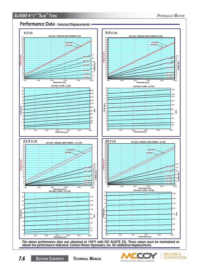
SL4500 4-1/2” “SLim” Tong
SecTion conTenTS7.6 TechnicaL manuaL
hyDRauLic moToR
Performance Data - Selected Displacements
The above performance data was obtained at 140OF with ISO 46(DTE 25). These values must be maintained to obtain the performance indicated. Contact Rineer Hydraulics, Inc. for additional displacements.
6 C.I.D.ACTUAL TORQUE AND POWER 6-CID
0102030405060708090
100110120130140150160170180190200
500 1000 1500 2000 2500 3000PRESSURE (psid)
TOR
QU
E(ft
-lbf)
0
10
20
30
40
50
60
70
POW
ER(H
P)
2000 RPM
100 RPM
2000 RPM
1200 RPM
400 RPM
100 RPM
800 RPM
1600 RPM
ACTUAL FLOW - 6 CID
0
5
10
15
20
25
30
35
40
45
50
55
60
65
0 500 1000 1500 2000 2500 3000PRESSURE (psid)
FLO
W(g
pm)
RPM800
1000
1200
1400
1600
1800
2000
200
400
600
100
9.5 C.I.D.
ACTUAL FLOW - 9.5 CID
0
5
10
15
20
25
30
35
40
45
50
55
60
65
70
75
80
500 1000 1500 2000 2500 3000PRESSURE (psid)
FLO
W(g
pm)
15001400
1200
1000
800
600
400
200100
1700
ACTUAL TORQUE AND POWER 9.5-CID
020406080
100120140160180200220240260280300320340360
500 1000 1500 2000 2500 3000PRESSURE (psid)
TOR
QU
E(ft
-lbf)
0102030405060708090100
POW
ER(H
P)
1700 RPM100 RPM
1700 RPM
900 RPM
300 RPM100 RPM
500 RPM
1300 RPM
RPM
11.5 C.I.D. ACTUAL TORQUE AND POWER - 11.5 CID
0255075
100125150175200225250275300325350375400425450
500 1000 1500 2000 2500 3000PRESSURE (psid)
TOR
QU
E(ft
-lbf)
0102030405060708090100110120130
POW
ER(H
P)
1600 RPM
800 RPM
200 RPM100 RPM
400 RPM
1200 RPM
1600 RPM100 RPM
ACTUAL FLOW - 11.5 CID
0
10
20
30
40
50
60
70
80
90
100
0 500 1000 1500 2000 2500 3000PRESSURE (psid)
FLO
W(g
pm)
1600
400
600
800
1000
1200
1400
100
200
RPM
15 C.I.D. ACTUAL TORQUE AND POWER - 15 CID
0255075
100125150175200225250275300325350375400425450475500525550575600
500 1000 1500 2000 2500 3000PRESSURE (psid)
TOR
QU
E(ft
-lbf)
0
25
50
75
100
125
150
POW
ER(H
P)
1500 RPM
100 RPM
1500 RPM
700 RPM
300 RPM100 RPM
500 RPM
1100 RPM
ACTUAL FLOW - 15 CID
0
10
20
30
40
50
60
70
80
90
100
110
500 1000 1500 2000 2500 3000PRESSURE (psid)
FLO
W(g
pm)
1500
1100
1300
500
700
900
100
300
RPM

SL4500 4-1/2” “SLim” Tong
SecTion conTenTS 7.7 TechnicaL manuaL
hyDRauLic moToR
For durable hydraulic motors that meet your demands, specify Rineer.For over 35 years, we have specialized in only one thing - engineering the right motor for your needs.Rineer delivers the performance you can count on.
Model CodeM015 - 61/62 -1S -015 -31 -B1 -TV -000
M015 - 61 = 015 Single SpeedM015 - 62 = 015 Two Speed
Options:62 = Two Speed Single Pilot
Open During Crossover63 = Two Speed Single Pilot
Closed During Crossover65 = Two Speed Double Pilot
Open During Crossover67 = Two Speed Double Pilot
Closed During Crossover1S = Std.1H = High Speed
006 = 6 in3 (98cc)/rev.007 = 7 in3 (115cc)/rev.008 = 8 in3 (131cc)/rev.009 = 9.5 in3 (156cc)/rev.
010 = 10.5 in3 (172cc)/rev.011 = 11.5 in3 (189cc)/rev.013 = 13 in3 (213cc)/rev.015 = 15 in3 (246cc)/rev.
30 = Keyed Shaft31 = Splined Shaft32 = Wheel Motor34 = Double Key50 = Retractable53 = API Thread
Bearing Package Selection
Seal - Package Selection
Special Code Designator
331 Breesport San Antonio, Texas 78216
210-341-6333 Fax: 210-341-1231 e-mail: [email protected]
Applications
Rineer Hydraulics, Inc. warrants that, at the time of shipment toPurchaser, our product will be free of defects in the material andworkmanship. The above warranty is LIMITED to defectiveproducts returned by Purchaser to Rineer Hydraulics, Inc., freightprepaid within four hundred and fifty-five (455) days from date ofshipment, or one (1) year from date of first use, whichever expiresfirst. We will repair or replace any product or part thereof which isproved to be defective in workmanship or material. There is noother warranty, expressed or implied, and in no event shall RineerHydraulics, Inc. be liable for consequential or special damages.Dismantling the product, operation of the product beyond thepublished capabilities or for purposes other than that for which theproduct was designed, shall void this warranty.
Limited Warranty Policy

SL4500 4-1/2” “SLim” Tong
SecTion conTenTS7.8 TechnicaL manuaL
hyDRauLic moToR
Standard Motor
Two Speed Motor
HYDRAULICS, INC.HYDRAULICS, INC.
R
MA
NU
FA
CT
UR
ER OF HYDRAU
LIC
MO
TO
RS
15 Series
Repair Manual
331 BREESPORT * SAN ANTONIO, TX 78216 * (210) 341-6333 FAX (210) 341-1231
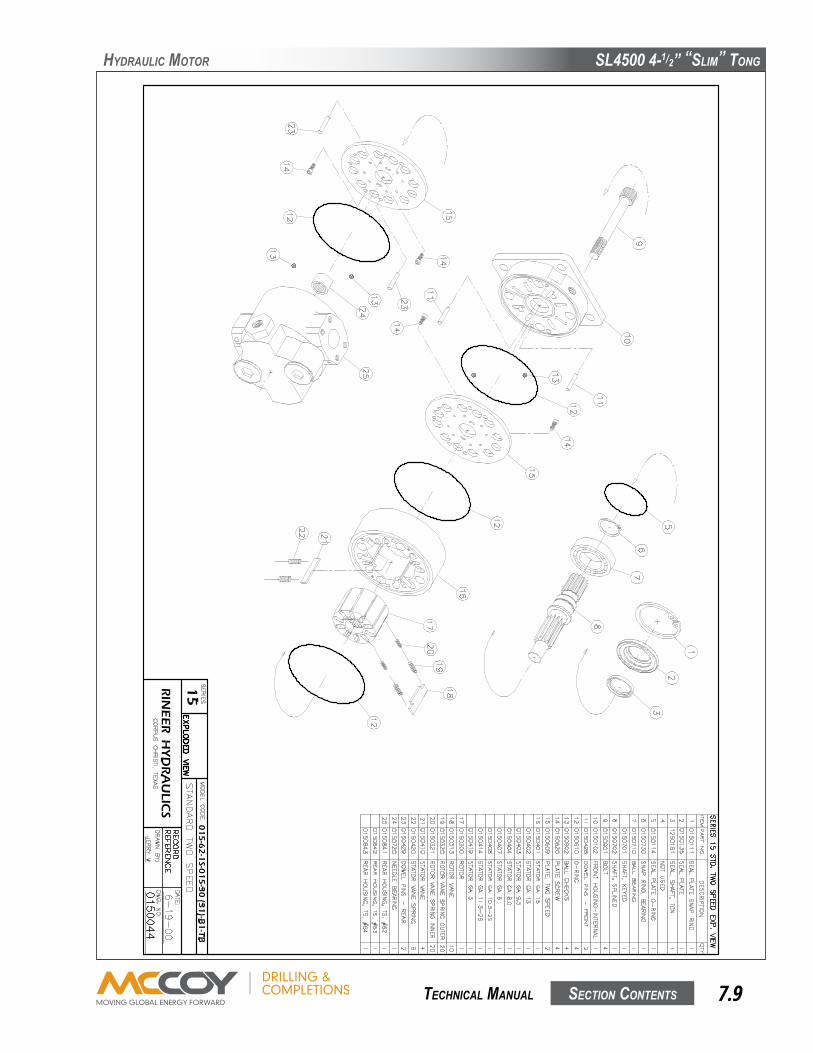
SL4500 4-1/2” “SLim” Tong
SecTion conTenTS 7.9 TechnicaL manuaL
hyDRauLic moToR

SL4500 4-1/2” “SLim” Tong
SecTion conTenTS7.10 TechnicaL manuaL
hyDRauLic moToR
WARNING: RINEER RECOMMENDS FOLLOWING ALL STANDARD SHOP SAFETY PRACTICES SPECIFICALLY INCLUDING WEARING OF EYE PROTECTION.
1
2
3
4
5
6
7
8
5
1) Remove snap ring
WARNING: Use caution when removing snap ring. If released accidentally it can become an airborne hazard.
1) Pry out shaft seal plate with two screw drivers.2) Remove seal plate o-ring from groove in bearing bore.
1) Loosen and remove 8 each 10-32 bolts.2) Pry off seal plate with screw driver.
Loosen and remove 8 each 3/8" bolts with 5/16" socket head wrench.
1) Press shaft out of bearing box.2) Proceed to step 9, disregarding steps 11 & 12
1) Loosen clamp screw in lock nut.2) Unscrew lock nut and remove.
Lift up on the bearing box to remove from motor.
1) Two of the 3/8" bolt holes are provided with jack screw threads.2) Insert a piece of 1/4" round stock by 2-1/2" long into each jack screw hole3) Screw two 7/16-14 bolts into the jack screw threads until the bearing box is free of the motor.
REMOVAL OF SHAFT SEAL
REMOVAL OF WHEEL MOTOR SEALPLATE AND BEARING BOX
DISASSEMBLY OF WHEEL MOTORBEARING BOX
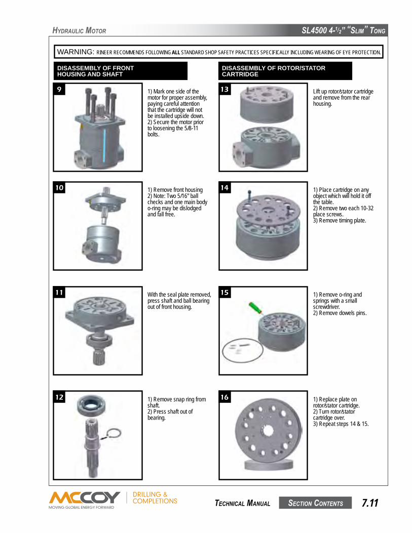
SL4500 4-1/2” “SLim” Tong
SecTion conTenTS 7.11 TechnicaL manuaL
hyDRauLic moToR
WARNING: RINEER RECOMMENDS FOLLOWING ALL STANDARD SHOP SAFETY PRACTICES SPECIFICALLY INCLUDING WEARING OF EYE PROTECTION.
9
10
11
12
13
14
15
16
6
1) Remove front housing2) Note: Two 5/16" ball checks and one main body o-ring may be dislodged and fall free.
1) Mark one side of the motor for proper assembly, paying careful attention that the cartridge will not be installed upside down.2) Secure the motor prior to loosening the 5/8-11 bolts.
With the seal plate removed, press shaft and ball bearing out of front housing.
1) Remove snap ring from shaft.2) Press shaft out of bearing.
1) Replace plate on rotor/stator cartridge.2) Turn rotor/stator cartridge over.3) Repeat steps 14 & 15.
1) Remove o-ring and springs with a small screwdriver.2) Remove dowels pins.
1) Place cartridge on any object which will hold it off the table.2) Remove two each 10-32 place screws.3) Remove timing plate.
Lift up rotor/stator cartridge and remove from the rear housing.
DISASSEMBLY OF FRONTHOUSING AND SHAFT
DISASSEMBLY OF ROTOR/STATORCARTRIDGE
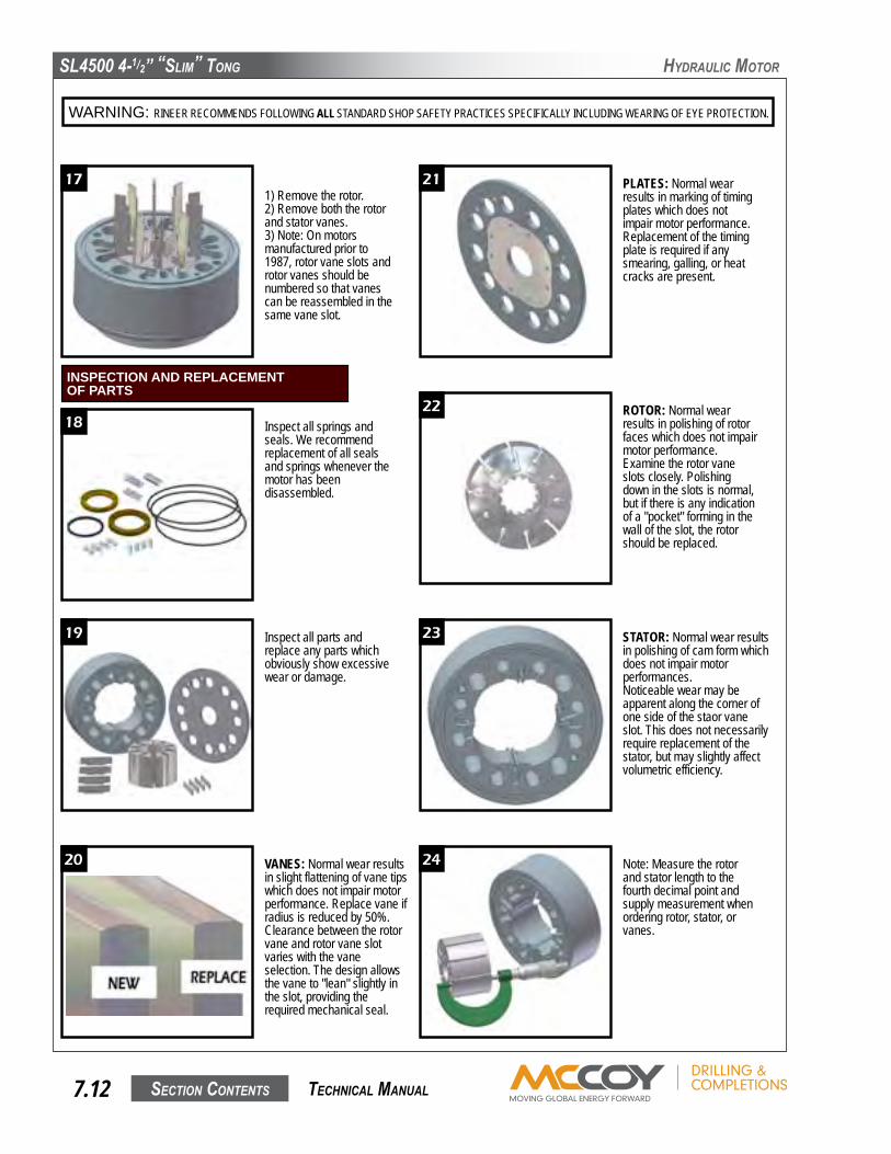
SL4500 4-1/2” “SLim” Tong
SecTion conTenTS7.12 TechnicaL manuaL
hyDRauLic moToR
WARNING: RINEER RECOMMENDS FOLLOWING ALL STANDARD SHOP SAFETY PRACTICES SPECIFICALLY INCLUDING WEARING OF EYE PROTECTION.
17 21
22
23
24
18
19
20
7
1) Remove the rotor.2) Remove both the rotor and stator vanes.3) Note: On motors manufactured prior to 1987, rotor vane slots and rotor vanes should be numbered so that vanes can be reassembled in the same vane slot.
Inspect all springs and seals. We recommend replacement of all seals and springs whenever the motor has been disassembled.
Inspect all parts and replace any parts which obviously show excessive wear or damage.
VANES: Normal wear results in slight flattening of vane tips which does not impair motor performance. Replace vane if radius is reduced by 50%.Clearance between the rotor vane and rotor vane slot varies with the vane selection. The design allows the vane to "lean" slightly in the slot, providing the required mechanical seal.
Note: Measure the rotor and stator length to the fourth decimal point and supply measurement when ordering rotor, stator, or vanes.
STATOR: Normal wear results in polishing of cam form which does not impair motor performances.Noticeable wear may be apparent along the corner of one side of the staor vane slot. This does not necessarily require replacement of the stator, but may slightly affect volumetric efficiency.
ROTOR: Normal wear results in polishing of rotor faces which does not impair motor performance.Examine the rotor vane slots closely. Polishing down in the slots is normal, but if there is any indication of a "pocket" forming in the wall of the slot, the rotor should be replaced.
PLATES: Normal wear results in marking of timing plates which does not impair motor performance.Replacement of the timing plate is required if any smearing, galling, or heat cracks are present.
INSPECTION AND REPLACEMENTOF PARTS
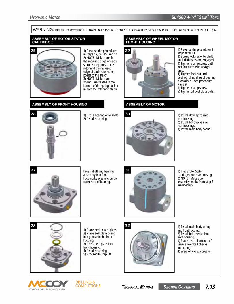
SL4500 4-1/2” “SLim” Tong
SecTion conTenTS 7.13 TechnicaL manuaL
hyDRauLic moToR
WARNING: RINEER RECOMMENDS FOLLOWING ALL STANDARD SHOP SAFETY PRACTICES SPECIFICALLY INCLUDING WEARING OF EYE PROTECTION.
25
26
27
28
29
30
31
32
8
1) Reverse the procedures in steps 17, 16, 15, and 142) NOTE: Make sure that the radiused edge of each stator vane points to the rotor and the radiused edge of each rotor vane points to the stator.3) NOTE: Make sure springs are seated in the bottom of the spring pocket in both the rotor and stator.
1) Press bearing onto shaft.2) Install snap ring.
Press shaft and bearing assembly into front housing by pressing on the outer race of bearing.
1) Place seal in seal plate.2) Place seal plate o-ring into groove in the front housing.3) Press seal plate into front housing.4) Install snap ring.5) Proceed to step 30.
1) Install main body o-ring into front housing.2) Install ball checks into front housing.3) Place a small amount of grease over ball checks and o-ring.4) Wipe off excess grease.
1) Place rotor/stator cartridge onto rear housing.2) NOTE: Make sure assembly marks from step 3 are lined up.
1) Install dowel pins into rear housing.2) Install ballchecks into rear housings.3) Install main body o-ring.
1) Reverse the procedures in steps 8 thru 3.2) Screw lock nut onto shaft until all threads are engaged.3) Tighten clamp screw until lock nut turns with a slight drag.4) Tighten lock nut until desired rolling drag of bearing is obtained - see procedure Page 9.5) Tighten clamp screw6) Tighten all seal plate bolts.
ASSEMBLY OF ROTOR/STATORCARTRIDGE
ASSEMBLY OF FRONT HOUSING
ASSEMBLY OF WHEEL MOTORFRONT HOUSING
ASSEMBLY OF MOTOR

SL4500 4-1/2” “SLim” Tong
SecTion conTenTS7.14 TechnicaL manuaL
hyDRauLic moToR
WARNING: RINEER RECOMMENDS FOLLOWING ALL STANDARD SHOP SAFETY PRACTICES SPECIFICALLY INCLUDING WEARING OF EYE PROTECTION.
33
34
35
36
B
A
9
1) Install dowel pins into rotor/stator cartridge.2) Pour a small amount of clean oil into the cartridge.3) Install front housing onto rotor/stator cartridge.4) Make sure alignment marks are lined up.
1) Install 5/8-11 bolts.2) Torque bolts to 50 ft./lbs.
1) Rotate shaft in both directions to assure that the shaft turns smoothly.2) Torque motor to 190 ft./lbs.3) Rotate shaft again in both directions to assure that the shaft turns smoothly.
NOTE: Spool should be oriented as shown for two speed motors with model codes 62, 63, 68, & 69.
NOTE: Slight design variations may exist in motors manufactured either before or after the printing of this manual.
SPOOL ASSEMBLY FOR THETWO SPEED MOTOR
1)� Clean ALL assembly parts w/ lacquer thinner.2)� Dip clampnut and clamping bolt separately in lacquer thinner. � (Steps 3 thru 10 must be conducted to completion ONE assembly at a time.)3)� Press bearing cups into bearing housing. Make sure they are pressed completely against bearing shoulders.4)� Coat inner race of large cone with #609 (green) Loctite and press cone onto the shaft. Make sure the cone is completely against the shoulder of the shaft.5)� Insert shaft and large cone into bearing housing.6)� Coat inner race of small cone with #609 (green) Loctite and press small cone onto shaft.7)� Apply #272 (red) Loctite to the clampnut threads of the shaft. Apply #242 (blue) Loctite to the threads of the clamping bolt and install in the clampnut.8)� Spin clampnut onto shaft with the "B" face towards bearings. After the nut threads are fully engaged, but prior to the nut contacting the bearings, �� tighten the clamping bolt until there is drag on the clamping nut (see note Fig. 1). Tighten the nut until a 20 to 30 inch pound rolling torque is achieved.9)� Tighten clamping bolt on clampnut to 70 inch pounds and recheck rolling torque. Apply inspectors lacquer to head of the bolt.10)� Allow a minimum of 24 hrs. to dry.
Figure 1
CUTAWAY
Note:The slit in the clampnut allows for loose assembly on the shaft. Once in position, the clampnut clamping bolt MUST be tightened to a slight drag in order to correctly engage the threads on the shaft to achieve the clamp force required.
FACE"A"
CLAMPING BOLT
FACE"A"
FACE"B"
WHEEL MOTOR SHAFT AND BEARING ASSEMBLY PROCEDURE
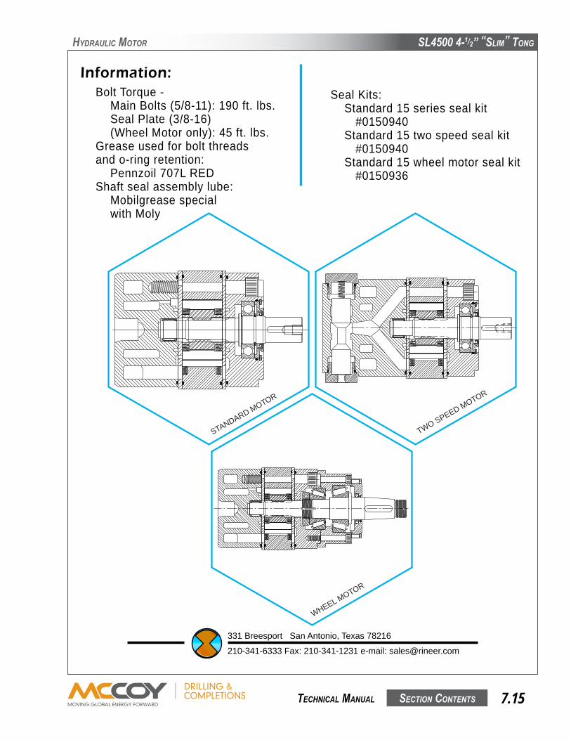
SL4500 4-1/2” “SLim” Tong
SecTion conTenTS 7.15 TechnicaL manuaL
hyDRauLic moToR
Information:Bolt Torque -� Main Bolts (5/8-11): 190 ft. lbs.� Seal Plate (3/8-16)� (Wheel Motor only): 45 ft. lbs.Grease used for bolt threadsand o-ring retention:� Pennzoil 707L REDShaft seal assembly lube:� Mobilgrease special� with Moly
Seal Kits:� Standard 15 series seal kit� � #0150940� Standard 15 two speed seal kit� � #0150940� Standard 15 wheel motor seal kit� � #0150936
331 Breesport San Antonio, Texas 78216
210-341-6333 Fax: 210-341-1231 e-mail: [email protected]
WHEEL MOTOR
STANDARD MOTOR
TWO SPEED MOTOR
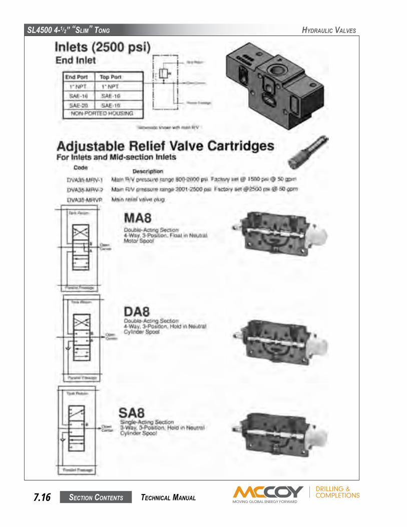
SL4500 4-1/2” “SLim” Tong
SecTion conTenTS7.16 TechnicaL manuaL
hyDRauLic VaLVeS

SL4500 4-1/2” “SLim” Tong
SecTion conTenTS 7.17 TechnicaL manuaL
hyDRauLic VaLVeS

SL4500 4-1/2” “SLim” Tong
SecTion conTenTS7.18 TechnicaL manuaL
hyDRauLic VaLVeS

SL4500 4-1/2” “SLim” Tong
SecTion conTenTS 7.19 TechnicaL manuaL
hyDRauLic VaLVeS
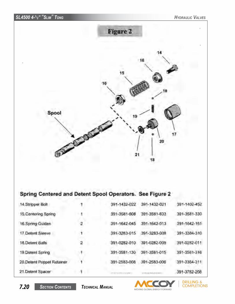
SL4500 4-1/2” “SLim” Tong
SecTion conTenTS7.20 TechnicaL manuaL
hyDRauLic VaLVeS

SL4500 4-1/2” “SLim” Tong
SecTion conTenTS 7.21 TechnicaL manuaL
hyDRauLic VaLVeS

SL4500 4-1/2” “SLim” Tong
SecTion conTenTS7.22 TechnicaL manuaL
hyDRauLic VaLVeS

SL4500 4-1/2” “SLim” Tong
SecTion conTenTS 7.23 TechnicaL manuaL
hyDRauLic VaLVeS

SL4500 4-1/2” “SLim” Tong
SecTion conTenTS7.24 TechnicaL manuaL
hyDRauLic VaLVeS

SL4500 4-1/2” “SLim” Tong
SecTion conTenTS 7.25 TechnicaL manuaL
hyDRauLic VaLVeS
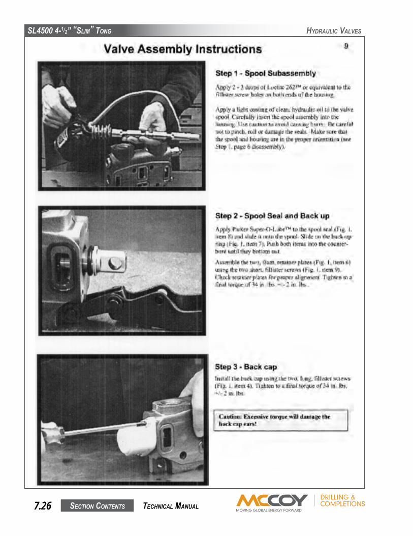
SL4500 4-1/2” “SLim” Tong
SecTion conTenTS7.26 TechnicaL manuaL
hyDRauLic VaLVeS

SL4500 4-1/2” “SLim” Tong
SecTion conTenTS 7.27 TechnicaL manuaL
hyDRauLic VaLVeS

SL4500 4-1/2” “SLim” Tong
SecTion conTenTS7.28 TechnicaL manuaL
hyDRauLic VaLVeS
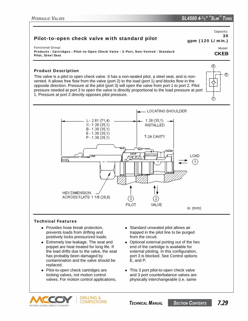
SL4500 4-1/2” “SLim” Tong
SecTion conTenTS 7.29 TechnicaL manuaL
hyDRauLic VaLVeS
Pilot-to-open check valve with standard pilotCapacity:
30gpm (120 L/min.)
Functional Group:Products : Cartridges : Pilot-to-Open Check Valve : 3-Port, Non-Vented : StandardPilot, Steel Seat
Model:
CKEB
Product DescriptionThis valve is a pilot to open check valve. It has a non-sealed pilot, a steel seat, and is non-vented. It allows free flow from the valve (port 2) to the load (port 1) and blocks flow in theopposite direction. Pressure at the pilot (port 3) will open the valve from port 1 to port 2. Pilotpressure needed at port 3 to open the valve is directly proportional to the load pressure at port1. Pressure at port 2 directly opposes pilot pressure.
Technical Features Provides hose break protection,
prevents loads from drifting andpositively locks pressurized loads.
Standard unsealed pilot allows airtrapped in the pilot line to be purgedfrom the circuit.
Extremely low leakage. The seat andpoppet are heat treated for long life. Ifthe load drifts due to the valve, the seathas probably been damaged bycontamination and the valve should bereplaced.
Optional external porting out of the hexend of the cartridge is available forexternal piloting. In this configuration,port 3 is blocked. See Control optionsE, and P.
Pilot-to-open check cartridges arelocking valves, not motion controlvalves. For motion control applications,
This 3 port pilot-to-open check valveand 3 port counterbalance valves arephysically interchangeable (i.e. same

SL4500 4-1/2” “SLim” Tong
SecTion conTenTS7.30 TechnicaL manuaL
hyDRauLic VaLVeS
use counterbalance valves. cavities, same flow path for a givenframe size). However, cartridgeextension dimensions from themounting surface may vary.
Stainless steel cartridge options P or Ware intended for use within corrosiveenvironments with all externalcomponents manufactured in stainlesssteel or titanium. Internal workingcomponents remain the same as thestandard valves.
Incorporates the Sun floating styleconstruction to eliminate the effects ofinternal parts binding due to excessiveinstallation torque and/orcavity/cartridge machining variations.
Technical DataU.S. Units Metric Units
Cavity T-2ACapacity 30 gpm 120 L/min.Pilot Ratio 3:1 3:1Maximum Operating Pressure 5000 psi 350 barMaximum Valve Leakage at 110 SUS (24 cSt) 1 drops/min. 0,07 cc/min.Series (from Cavity) 2Valve Hex Size 1 1/8 in. 28,6 mmValve Installation Torque 45 - 50 lbf ft 60 - 70 NmModel Weight .50 lb 0,25 kgSeal Kits Buna: 990-202-007Seal Kits Viton: 990-202-006
Option Selection
CKEB-X C N
Preferred Options
Control Cracking PressureExternalMaterial/SealMaterial
X Standard Pilot C 30 psi (2 bar) N Buna-N
Standard OptionsL Manual Load Release A 4 psi (0,3 bar)
B 15 psi (1 bar)D 50 psi (3,5 bar)E 75 psi (5 bar)F 100 psi (7 bar)
P Stainless/Buna-N
V VitonW Stainless/Viton
Customer specified setting stamped on hex +$1.10
Related Information : Explanation of Sun cartridge control options - US units. Explanation of Sun cartridge control options - metric units.
Copyright © 2003 Sun Hydraulics Corporation.All rights reserved.
Terms and Conditions - Statement of Privacy

SL4500 4-1/2” “SLim” Tong
SecTion conTenTS 7.31 TechnicaL manuaL
hyDRauLic VaLVeS
Pilot-to-open, spring biased closed, unbalancedpoppet logic element
Capacity:60 gpm (240 L/min.)
Functional Group:Products : Cartridges : Corrosion Resistant : Logic Element : Unbalanced Poppet,Pilot-to-open, Switching Element, Spring biased closed, External Pilot Port 3pilot source
Model:
LKHC
Product DescriptionThese unbalanced poppet, logic valves are 2-way switching elements that arespring-biased closed. Pressure at either work port 1 or 2 will further bias thevalve to the closed position while pressure at port 3 will tend to open it. Theforce generated at port 3 must be greater than the sum of the forces acting atport 1 and port 2 plus the spring force for the valve to open. NOTE: The pilotarea (port 3) is 1.8 times the area at port 1 and 2.25 times the area at port 2.
Technical Features Because these valves are unbalanced,
operation is pressure dependent.Opening and closing of the poppet arefunctions of the force balances on threeareas: 1) Port 1 = 100%, Port 2 = 80%,and Port 3 = 180%.
These valves are pressure responsiveat all three ports, therefore it isessential to consider all aspects ofsystem operation through a completecycle. Pressure changes at any oneport may cause a valve to switch from aclosed to an open position, or viceversa. All possible pressure changes inthe complete circuit must be consideredto assure a safe, functional systemdesign.

SL4500 4-1/2” “SLim” Tong
SecTion conTenTS7.32 TechnicaL manuaL
hyDRauLic VaLVeS
These valves have positive sealsbetween port 3 and port 2.
Stainless steel cartridge options P or Ware intended for use within corrosiveenvironments with all externalcomponents manufactured in stainlesssteel or titanium. Internal workingcomponents remain the same as thestandard valves.
Incorporates the Sun floating styleconstruction to eliminate the effects ofinternal parts binding due to excessiveinstallation torque and/orcavity/cartridge machining variations.
Technical DataU.S. Units Metric Units
Cavity T-17ACapacity 60 240 L/min.Area Ratio, A3 to A1 1.8:1Area Ratio, A3 to A2 2.25:1Maximum Operating Pressure 5000 350 barMaximum Valve Leakage at 110 SUS (24 cSt) 10 10 drops/min.@70 barPilot Volume Displacement .15 2,5 ccSeries (from Cavity) 3U.S. Patent # 4,795,129Valve Hex Size 1 1/4 31,8 mmValve Installation Torque 150 - 160 200 - 215 NmSeal Kits Buna: 990-017-007Seal Kits Viton: 990-017-006
Option Selection
LKHC-X D N
Preferred Options
ExternalControl Cracking Pressure Material/Seal
Material
Standard OptionsX Not Adjustable N Buna-N
V Viton
Customer specified setting stamped on hex +$1.10
Related Information : Explanation of Sun cartridge control options - US units. Explanation of Sun cartridge control options - metric units.
Copyright © 2003 Sun Hydraulics Corporation.All rights reserved.
Terms and Conditions - Statement of Privacy

SL4500 4-1/2” “SLim” Tong
SecTion conTenTS 7.33 TechnicaL manuaL
hyDRauLic VaLVeS
Pilot operated, balanced piston relief valve Capacity:12 gpm (45 L/min.)
Functional Group:Products : Cartridges : Relief : 2 Port : Pilot Operated, Balanced Piston
Model:RPCC-KAN
Product DescriptionPilot-operated, balanced-piston relief cartridges are normally closed pressureregulating valves. When the pressure at the inlet (port 1) reaches the valvesetting, the valve starts to open to tank (port 2), throttling flow to regulate thepressure. These valves are accurate, have low pressure rise vs. flow, they aresmooth and quiet, and are moderately fast.
Download
Technical FeaturesWill accept maximum pressure at port 2; suitablefor use in cross port relief circuits. If used in crossport relief circuits, consider spool leakage.
The main stage orifice is protected againstcontamination.
Minimum setting is 75 psi (5 bar) for all springranges.
All 2-port relief cartridges (except pilot reliefs) arephysically and functionally interchangeable (sameflow path, same cavity for a given frame size).
Not suitable for use in load holding applicationsdue to spool leakage.
Incorporates the Sun floating style construction tominimize the possibility of internal parts bindingdue to excessive installation torque and/orcavity/cartridge machining variations.
Back pressure on the tank port (port 2) is directlyadditive to the valve setting at a 1:1 ratio.
Technical DataU.S. Units Metric Units
Cavity T-162ACapacity 12 gpm 45 L/min.Adjustment - Number of Clockwise Turns to Increase Setting 5Factory Pressure Settings Established at 4 gpm 15 L/min.Maximum Operating Pressure 5000 psi 350 bar
Maximum Valve Leakage at 110 SUS (24 cSt) 2 in³/min.@1000 psi 30 cc/min.@70 barResponse Time - Typical 10 msSeries (from Cavity) Series 0Valve Hex Size 3/4 in. 19,1 mmValve Installation Torque 25 - 30 lbf ft 35 - 40 NmAdjustment Screw Internal Hex Size 5/32 in. 4 mmAdjustment Nut Hex Size 9/16 in. 15 mmAdjustment Nut Torque 108 lbf in. 12 NmModel Weight 0.30 lb. 0.14 kg.Seal Kits - Cartridge Buna: 990-162-007Seal Kits - Cartridge Viton: 990-162-006
RPCC-KAN
Control Adjustment Range External Material/SealMaterial
K Handknob A75 - 3000 psi (5 - 210bar), 1000 psi (70 bar)Standard Setting
+0.00 N Buna-N +0.00
When the control is F, the range must be A or W
Customer specified setting stamped on hex $1.10
Explanation of Sun cartridge control options - US units.Explanation of Sun cartridge control options - metric units.Two-piece, floating cartridge construction.
| | | | | |

SL4500 4-1/2” “SLim” Tong
SecTion conTenTS7.34 TechnicaL manuaL
hyDRauLic VaLVeS
Maximum Valve Leakage at 110 SUS (24 cSt) 2 in³/min.@1000 psi 30 cc/min.@70 barResponse Time - Typical 10 msSeries (from Cavity) Series 0Valve Hex Size 3/4 in. 19,1 mmValve Installation Torque 25 - 30 lbf ft 35 - 40 NmAdjustment Screw Internal Hex Size 5/32 in. 4 mmAdjustment Nut Hex Size 9/16 in. 15 mmAdjustment Nut Torque 108 lbf in. 12 NmModel Weight 0.30 lb. 0.14 kg.Seal Kits - Cartridge Buna: 990-162-007Seal Kits - Cartridge Viton: 990-162-006
RPCC-KAN
Control Adjustment Range External Material/SealMaterial
K Handknob A75 - 3000 psi (5 - 210bar), 1000 psi (70 bar)Standard Setting
+0.00 N Buna-N +0.00
When the control is F, the range must be A or W
Customer specified setting stamped on hex $1.10
Explanation of Sun cartridge control options - US units.Explanation of Sun cartridge control options - metric units.Two-piece, floating cartridge construction.
| | | | | |