Embed Size (px)
Citation preview

1
TECHNICAL MANUAL INSTRUCTIONS FOR: INSTALLATION – OPERATIONS – MAINTENANCE
DĨATHER
DIATHERMIC (HEAT-TRANSMITTING) OIL HEATERS

2
Dear Customer, Many thanks to have chosen an UNICAL heater. It's in your own interest to follow the instructions as described in this manual and carry out the scheduled maintenance by qualified personnel in order to hold the highest efficiency level of the device. The missed compliance with the instructions of this manual, will void the guarantee.

3
CONTENTS
Pag. 4 – general instructions Pag. 5 – safety main rules Pag. 6 – introduction Pag. 7 – the diathermic oil Pag. 8 – heater description Pag. 10 – technical data and dimensions mod. DĨATHER Pag. 11 – diathermic oil system scheme Pag. 13 – system components
Pag.13: oil circulation electro-pumps Pag.14: differential pressure switch Pag.14: tapping manual valves Pag.15: diathermic oil filter Pag.16: operations and safety thermostats, thermometers Pag.17: oil surge tank Pag.17: connection pipe to the oil surge tank Pag.18: diathermic oil trap tank
Pag. 19 – heater installation room Pag. 20 – electric system Pag. 21 – stack effluence discharge Pag. 21 – fuel supply Pag. 22 – burner connection Pag. 23 – door opening and rigging Pag. 24 – hydraulic circuit Pag. 26 – system replenishment Pag. 26 – first start
Pag.26: preliminary operations Pag.27: cold start Pag.27: hot start
Pag. 28 – starts and following checks Pag. 29 – system stoppage Pag. 29 – maintenance Pag. 30 – diathermic oil check Pag. 31 – suggested spares Pag. 31 – troubleshooting
4
GENERAL NOTICES The instructions manual is essential and integral part of the product . Make sure that the manual is always enclosed with the device, in order that if the device is sold or transferred, the new owner and/or the assembler can use it. This device must be used for the intended use. Improper use, maintenance, rigging and installation mistakes will void the guarantee and exclude any contractual and extra-contractual manufacturer liability for any damage to third parties. The manufacturer responsibility is excluded for every damage to third parties due to an hazard obvious for the user and not avoided by the adoption normal safety requirements. After the packaging removal ascertain the heater conditions. If a doubt could arise, do not use the device and call the supplier. Keep away from reach of children the packaging components (wooden gauge, pins, clamps, plastic bags, polystyrene). The installation must be carried out in compliance with the running rules, in accordance with the manufacturer instructions and by qualified personnel (personnel skilled for diathermic oil systems). To assure the right operations of the system, it is mandatory that the scheduled maintenance (as prescribed by the Manufacturer) is carried out by qualified personnel. Use genuine spare parts only.

5
MAIN SAFETY REQUIREMENTS The use of the devices working with electric energy and fuels implies a strict observance of some fundamental rules: The use of the device is forbidden to children and no skilled personnel. In case of gas smell, do not use electric switches, electric devices, phones and any other device that could produce sparks, but : - open immediately doors and windows - close the fuel valves - call qualified personnel Do not touch the system with wet or humid body parts and/or bare feet. Close electric power and fuel supply before starting the maintenance or cleaning operations. Do not pull, disconnect or twist the electric cables coming from the heater, also if it is disconnected from the electric power supply. Do not cover or reduce the area of the ventilation windows: it could lead to explosive and toxic mixture build-up. On the other side, it can decrease the combustion quality and increase air pollution. Avoid the exposure of the system to the atmospheric agents .
� If the electric supply cable is damaged, call qualified personnel for the replacement;
� Do not install electric cables (or remove immediately if found installed)
on the metallic lines of the system or close to heat sources.
� Do not touch device hot parts (door) because they can stay hot after a short stop also.
If oil leaks are present, shut-off the system and call qualified personnel. ATTENTION: in case of fire, do not use water (oil floats and propagates fire), but use powder and CO2 extinguishers.

6
INTRODUCTION The diathermic oil systems use a diathermic fluid as carrier for heat transfer and, for its particular characteristics, is better than water and steam . The main characteristic of a diathermic oil (mineral or synthetic) is the high boiling temperature (more than 350° C) at standard atmospheric pressure: then it is possible to reach high temperatures without to use high pressure values. The main advantages of a diathermic oil system are:
- High operating temperature at atmospheric pressure ; - No scaling and corrosion as water; - Exemption from the patent tenancy ISPEL (accordingly to Italian laws), also for the indirect production (by means of exchangers) of steam or superheated water (art. D.M. 21/05/1974);
- Exemption from regulations for hot or superheated liquids under pressure (D.M. 01/12/1975 Collections “R” and “H” ed. 1982 – Italian laws)
The main failure of this systems is the possible spoilage of the oil (cracking and oxidation) that can be avoided taking the following actions:
- Oil periodic check (chemical analysis); - Oil change in accordance with the chemical analysis results ; - Use of the oil at a maximum temperature lower than maximum
allowable for that oil type; - Right positioning and connection of the oil surge tank ; - Maintenance of the pump and safety devices controlling the right oil
circulation and temperature in the heater. For these types of system, other provisions must be taken as:
- Higher lines heat insulation due to higher operating temperature; - No threaded joints : use flanged or welded ones only ; - Do not use non-ferrous material, especially copper and its alloys; - Avoid that oil leaks could pollute the environment.

7
THE DIATHERMIC OIL The commercial diathermic oils are divided in two classes:
� mineral oils � synthetic oils
The first ones are cheaper and have working temperature of about 300 °C; the synthetic oils are more expensive and have higher working temperature (350°C and more). The parameters a diathermic oil choice are the following: - max working temperature ; - pour point (lowest temperature at which an oil will continue to flow when it
is cooled under standardized conditions) - vapour pressure less 600 mbar at 300°C (to avoid system pressurization) Hereafter a list of suggested diathermic oils : trademark and type Oil type Max working
Temperature °C
Pourpoint °C
Vapour pressure at
300°C Mbar
EURAL “TERMIC 32” mineral 315 - 9 106,6 ESSO “ESSOTHERM 500” mineral 315 - 9 106,6 IP “FORNOLA OILS 30” mineral 300 - 12 6,7 TOTAL “SERIOLA 2100” mineral 305 - 9 80 FINA “CALORAN IT 32” mineral 320 - 12 65 LEVENIT “THERMOIL 1500” mineral 315 - 9 80 AGIP “ALARIA 3” mineral 305 - 9 / Elf Atochem “JARYTHERM DBT”
synthetic 350 - 24 250 (a 320°C)
SOLUTIA “THERMINOL 66” synthetic 345 - 32 307,3 SOLUTIA “THERMINOL SP” synthetic 315 - 40 450 DIATHERMIC OIL SPOILAGE PHENOMENA Mainly they are: cracking and oxidation . The cracking occurs when the maximum allowable oil temperature is exceeded (overheating): some molecular bridge broke building-up carbon and volatile substances. The first ones adhere inside the pipe reducing gradually the cross-area (sclerosis), while the volatile substances build-up vapor bags leading to operations failures and pumps cavitations. The oxidation causes insoluble deposits build-up and occurs when the oil enter in contact with air at temperatures higher than 60°C: this one can occur in the surge tank. This item, then, has a particular design.

8
HEATER DESCRIPTION The diathermic oil heather DĨATHER is mono or multi-pipe type and with pressurized combustion. The coil, with two concentric rings and bottom-shield, is composed by closed spiral pipes. The pipes are made of high quality steel, “unwelded” type and large thickness. The first ring forms a large feed flame boiler, accessible through a hinged door, on which a naphtha, diesel, gas or L.P.G. burner can be installed. The door is insulated with insulating and refractory material and is equipped with flame sight glass and burner-plate The second ring is the fuel route with three smoke loops: in a such way, all the useful area is used and low NOx number burners can be installed. The coil is inserted in smoke sealed metal sheet cylinder that forms the heater body. The heater body bottom is bolted, insulated and equipped with cleaning door and smoke exhaust fitting. The external insulation is obtained with a double layer of high density rock wool, covered by aluminum or stainless steel. The maximum operating temperature for DĨATHER heater is 300°C, while the heat drop (inlet-outlet oil temperature difference) is within 35 and 42°C. On request, heater with higher temperature and different heat drops can be supplied.

9
Smoke circuit of DĨATHER heater:
10
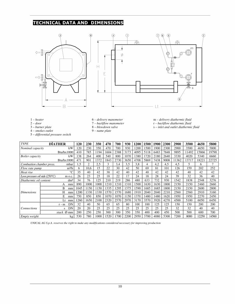
TECHNICAL DATA AND DIMENSIONS
1 – heater 2 – door 3 – burner plate 4 – smokes outlet
5 – differential pressure switch
6 – delivery manometer 7 – backflow manometer 8 – blowdown valve 9 – name plate
m – delivery diathermic fluid
r – backflow diathermic fluid
s – inlet and outlet diathermic fluid
TYPE DĨATHER 120 230 350 470 700 930 1200 1500 1900 2300 2900 3500 4650 5800
Nominal capacity kW 120 230 350 470 700 930 1200 1500 1900 2300 2900 3500 4650 5800
Btu/hx1000 410 785 1194 1604 2388 3173 4095 5118 6483 7848 9895 11492 15866 19790
Boiler capacity kW 138 264 400 540 800 1070 1380 1720 2180 2640 3330 4020 5340 6660
Btu/hx1000 471 901 1372 1843 2730 3650 4708 5869 7438 9008 11362 13717 18221 22725
Combustion chamber press. mbar 1,5 2 2,5 3 3,4 3,5 3,8 4 4,2 4,5 4,5 5 6 7
Flow rate pump m³/h 6 10,6 15 22 30 42 50 69 81 101 126 159 202 252
Heat rise °C 35 40 42 38 42 40 42 40 42 42 42 40 42 42
Loos pressure oil side (250°C) m o.c. 26 23 25 18 22 17 24 18 28 24 39 32 36 40
Diathermic oil content dm³ 34 76 125 210 219 286 480 633 732 930 1542 1838 2548 3276
A mm 890 1000 1000 1210 1210 1310 1500 1630 1630 1800 2150 2150 2460 2660
B mm 1045 1150 1150 1335 1295 1375 1590 1685 1685 1800 2150 2150 2600 2800
Dimensions H mm 1200 1330 1330 1570 1570 1680 1910 2040 2040 2210 2560 2560 2910 3160
E mm 750 850 850 1070 1070 1150 1370 1480 1480 1620 1950 1950 2270 2450
Lt mm 1260 1650 2100 2320 2570 2970 3170 3570 3920 4270 4500 5100 6050 6450
r - m DN 32 40 50 65 65 80 100 100 125 125 150 150 200 200
Connections s DN 20 20 25 25 25 25 25 25 25 25 32 32 40 40
stack Ø mm 200 250 250 300 300 350 350 400 400 450 500 500 600 700
Empty weight kg 530 780 1000 1520 1700 2200 2950 3700 4080 5300 7200 8000 12250 14560
UNICAL AG S.p.A. reserves the right to make any modifications considered necessary for improving production

11
DIATHERMIC OIL INSTALLATION SCHEME

12
LEGENDA of system scheme (page 11): TSAH = oil max temperature alarm TI = thermometer TC = adjustment thermostat PDA = differential pressure switch PI = pressure gauge LSAL = low level alarm LI = level indicator Specifications for the oil loading group To load the system with P300 pump :
1. open valves V304 and V301, 2. close valves V302, V303 and V305 3. start the pump
During operations:
1. valves V304 e V302: open 2. valves V301, V303 and V305 : closed 3. pump P300: stop
To unload the system by pump P300:
1. open valves V303 and V305, 2. close valves V301, V302 and V304 3. start the pump
NOTICES
� The system scheme (page 11) is open vessel type and equipped with all
components assuring the maximum operating safety and management of the system (if properly dimensioned) ;
� Some components as showed in the scheme are not standard equipment: during the commercial agreement their supplier can be agreed;
� The scheme at page 11 is the basic diathermic oil system: this is the base for more complex systems;

13
SYSTEM COMPONENTS OIL CIRCULATION ELECTRO-PUMPS The circulation pump of the diathermic oil is a system main components and must be chosen in accordance with the following criteria: - Single impeller centrifugal pump, diathermic oil type, self-lubricating and self- cooling with mechanical sealing or sealing ring in high temperature-proof material;
- max operating temperature: 320 °C; - modular cast iron or steel body The rate of flow of the pump is depending by the chosen heather : the value is showed in the technical data table. The prevalence of the pump must be little higher to the sum of the losses of load of the whole oil circuit: the loss of load of any of our heaters is showed in the technical data table. The power of the motor coupled to the pump must be higher than the rated one because, with the cold oil (more density), the motor requires an higher power. The N.P.S.H. value show the minimum necessary to the pump for proper operations. This value must not be lower of the surge tank height (from the pump) less eventual drags. If this value is not observed, pump cavitations occurs and the right rate of flow, inside the boiler, is not assured. IT IS ABSOLUTELY REQUIRED TO GUARANTEE THE OIL RIGHT RATE OF FLOW: this to avoid the diathermic oil cracking and the subsequent damage of the coil. In the diathermic oil systems there two installation chances: 1) only one circulation pump, providing for a spare pump immediately
available; 2) two circulation pumps in parallel ; In the first case, a pump failure stops the system with the aggravating factor that, if the failure occurs at operating temperature, the oil stopped in the boiler could overheat. In the second case, the system stoppage is very short: the required time to turn a selector, to close and open two valves. The oil is not damaged and the maintenance can be carried out at the right time.

14
In any case it is strongly recommended the installation of expansion compensating device on the pump inlet and outlet doors, in order to avoid any mechanical strengthen the pump . The pump must be installed on the ground or on a strong metallic frame. DIFFERENTIAL PRESSURE SWITCH It is a very important component for the control of the right oil rate of flow in the heater. All our heater are equipped with a differential pressure switch DANFOSS RT 260A (range 0.5 - 4 bar) connected with oil inlet/outlet, fitted with valves and pressure gauges. The safety is obtained connecting the pressure switch to the electric circuit that stops the burner. The connection must be made on the terminal N.A. of the pressure switch, in order that the burner stop occurs when the pressure difference is lower than the prescribed value. To set the rigging pressure, operate as follows:
� on the technical data table of our heaters, take the loss of load value - oil side (i.e. 25 m o.c.);
� divide the value per 13 and round off by defect (i.e. 25 / 13 = 1.9); � subtract 0,4 from the result and it is obtained the pressure to set on the
pressure switch (i.e. 1.9 – 0.4 = 1.5 bar). To rig the pressure switch, open the front cover and rotate the ring up to the rigging value. If the differential pressure switch operates, the reset occurs at a pressure 0.3 bar higher than the rigging pressure (fixed differential) MANUAL TAPPING VALVES The valves used in diathermic oil systems must have specific characteristics :
� to have a bellows seal (maintenance free) and not stuffing box; � nodular cast iron and fit for diathermic oil ; � to withstand 300 °C at least.

15
DIATHERMIC OIL FILTER On the system it is necessary to provide only one filter upstream of the circulation pump(s). The filter must have the following characteristics:
� must be of nodular cast iron or steel and fit for diathermic oil ; � must withstand 300 °C at least. � must have a filter element with large mesh (1.5 - 2 mm) for low drag to
oil flow . Due to particular installation shared with the oil surged tank connection (immediately before the circulation pump) it is necessary for the filter cleaning to empty the surge tank in the following way: we are suggesting (see scheme at pag. 12) to connect the fitting to the surge tank upstream the valve and the filter of the circuit. In this case, it is necessary : - calculate the surge tank height taking in account the load losses of the
valve and filter ; - insert a differential pressure switch connected before and after the filter
(fitted with pressure gauges and taps) . This safety device stops the burner if the filter is clogged.
The filter cleaning is more easy and the system has a supplementary safety device. We suggest to use pressure switch DANFOSS RT 262A (range 0.1 – 1.5 bar), connecting, on N.C. terminal, to the electric circuit blocking the burner. The pressure switch rigging is established after the first start, according to the pressure difference given by the pressure gauges and increased of 0.2 bar. ATTENTION to the hydraulic connections of the pressure switch : if they are installed in a reverse mode, the pressure switch will never give and alarm !
16
OPERATION AND SAFETY THERMOSTATS, THERMOMETERS The heater needs: � a safety pressure switch on the oil outlet of the boiler, and adjusted at
300°C with manual reset; � one or more regulation thermostats of the burner on the oil outlet on the
boiler; � a delayed switching-off thermostat of the oil pumps on the oil inlet in the
boiler; � a thermometer on the oil outlet ; � a thermometer on the oil inlet ;
The safety thermostat with manual reset stops the burner as the max allowable temperature is reached . The regulation thermostat switch on and off the burner at the required temperature. The delayed switching off thermostat keep on the oil pumps up to the temperature drops below 150 °C: this occurs at the system switching off and preserves the diathermic oil by the overheating . This instruments (digital) are installed in our electric panels supplied with the heaters.
17
OIL SURGE TANK This tank absorbs the volume dilatation of the oil during the heating process. The tank must have an oil/air contact surface very reduced as possible, and than it will be cylindrical and vertical. Considering that the diathermic oil volume increase is about 20% (from ambient temperature to 300°C), the surge tank shall have a capacity 40% higher than the total oil quantity in the system. With oil not heated, the tank is ¼ filled and, with oil heated, the maximum is ¾ of its volume. The surge tank needs also :
� visual level gauge � minimum level alarm floater (with burner stop and manual reset) at a
little bit less ¼ of the capacity; � max temperature alarm thermostat (with burner stop and manual reset)
at 60°C in order to avoid the oil oxidation; � thermometer; � discharge valve;
The oil surge tank is not insulated and installed upside the circulation pumps, considering also load losses (filter and valves of the circuit) that are added in the connection between the surge tank and circulation pump inlet. The surge tank must be positioned on the system highest point: a drip pan must be installed downside the tank for eventual leaks. If there is not the danger of freezing and the meteorological conditions allow it, the surge tank can be positioned outdoor. CONNECTING PIPE TO THE SURGE TANK The surge pipe must be dimensioned as showed in the table, without tapings, with a lay-out not leading to fluid convective motions, not insulated but, if the surge tank temperature should be very high, it must be cooled. Heater rated power Up to kW
Rated diameter of the surge pipe (mm)
600 20 1000 25 1900 32 3000 40 4700 50 7000 65

18
DIATHERMIC OIL TANK This service tank is for the system loading and unloading. Generally it is cylindrical, horizontal, atmospheric type, with cradles and hatchway with sleeves for hydraulic connections. The tank has a capacity 1.5 times the oil quantity in the system. It is usually positioned below the system to allow the oil drain. Do not install the tank underground (even with double wall or tarred): the best solution is to install it inside a watertight concrete vat with a metallic closing or hatchway. But the tank can connect indirectly the surge tank with the external atmosphere, connecting with a close pipe the surge tank to the tank (see scheme fig. 11): this pipe has the functions of : vent, discharge and overflow. The minimum dimensions of the connecting pipe and vent are as follows:
Heater rated power Up to kW
Overflow & vent pipe rated diameter (mm)
600 25 1000 32 1900 40 3000 50 4700 65 7000 80
Close to the tank, there is the system charge pump with its valves group. In accordance with scheme of fig. 11, the pump can be used to load, re-fill and discharge the system .

19
INSTALLATION ROOM
The heater shall be installed in a room built in accordance with the safety requirements in force and with proper ventilation doors. The room is for thermal central only. No admittance to the room of unauthorized personnel The space must be enough to allow maneuver and maintenance of all system components (pumps, valves, filters, heat exchangers etc.) The floor must be horizontal and in a such way to hold the base structures A sufficient space must be to open the door with the burner installed. A minimum of 0.8 m of space must be provided on the other sides The room must have, on the access doors, a shoulder in order to form a drip pan for oil leaks. Culverts must be provided to install discharge lines and vents from the system to the tank. ATTENTION: if the burner is supplied by gas with a specific weight higher than air, the electrical components must be installed at 0.5 m minimum from the ground.

20
ELECTRICAL SYSTEM The electrical system must be realized in accordance with the safety requirements in force and must be dimensioned for the power used by the system The electrical safety of the device is guaranteed only when it is duly grounded accordingly to the safety requirements. The manufacturer is not liable for the damages due to caused by the lack of the grounding. The correct dimension of the electric system for the max. absorbed power should be checked by qualified personnel making sure particularly that the cable cross section are fitting with the max. absorbed power of the device. The electrical system must be realized by qualified personnel only. Do not use adapters, multiple plugs and/or additional wires to connect the system to the general power supply network, but use a bi-polar switch only. The electric panels installed on our heaters provide for three-phases 400V – 50 Hz, while the auxiliary circuit is low voltage type (24V): different voltage on request. The components of the panels are manufactured by the best national and foreign trade marks. The assembly is made with the most advanced techniques in order to allow the maximum operating safety and an easy control of the several equipments. On request, it is available an instrument panel containing the safety and regulation thermostats only, with mono-phase 230V-50Hz . The conformity certificate and the electric diagram is supplied.

21
COMBUSTION PRODUCTS DISCHARGE
The proper coupling of burner/boiler/chimney allow a relevant reduction of the consumptions and an optimum combustion with low air pollution. The FLUE (chimney) shall be heat, mechanical stress and condensate resistant, thermally insulated, sealed, with the same cross area, vertically positioned and dimensioned in accordance with the law requirements. The CONNECTION BEETWEEN BOILER AND CHIMNEY shall be realized accordingly to the law and rules requirements with rigid sealed conducts resistant to the temperature, condensate and mechanical stress. The joints must withstand 500°C at least. Chimneys and joints between boiler and chimneys if not proper dimensioned and shaped could amplify the combustion noise, causing to deteriorate the combustion parameters, generate condensate problems. WARNING: THE DISCHARGE LINES NOT INSULATED ARE AN HAZARD. FUEL SUPPLY The fuel supply pipe-line shall be realized in accordance with the law requirements and by qualified personnel only. Before the installation, all the internal fuel lines must be deeply cleaned. Check the internal and external tightness of the fuel system, especially if gas is used. Check if the fuel system is equipped with safety devices as required by the law requirements. Do not use the fuel lines as electric ground Check that the boiler is fitted for the available fuel type.

22
BURNER CONNECTION For the burner installation, electric connections and required riggings, go to the burner user’s manual. Check the correct choice of the burner for the heater controlling the technical data of both devices. The burner nozzle must have the following dimensions:
FP fiber jacket
L
Heater model . burner nozzle min./max L mm
150 / 200
190 / 250
DIATER 120
DIATER 230 - 350
DIATER 470 - 1200
DIATER 1500 - 2300
DIATER 2900 - 5800
220 / 300
220 / 300
250 / 350
Fit strongly the burner to the door, by the means of the fixing plate in order that the flame is parallel and centered in the furnace; if not, combustion problems could arise with damage to the boiler. IMPORTANT: after the burner installation, fill the space (eventually) between the nozzle and the door hole with heat 1000°C resistant material (FP fiber jacket). In a such way, the door is not overheated and its deformation is avoided. If the burner is provided of air inlet, connect it, by the means of a rubber hose, to the plug on the flame gauge: in a such way the glass will remain clean. If the burner has no air intake, remove the intake on the flame gauge and close with a R1/8 plug. The fuel connections to the burner must be positioned in a such way to allow the complete opening of the door with the burner installed.

23
DOOR OPENING AND RIGGING On DĨATHER types, up to mod. 2300, the door can be opened from both sides. On DĨATHER types, from 2900 to 5800, the door can be opened from left side to right side (reverse opening on request) Only for DĨATHER up to mod. 2300 To change the opening of the door by the means of lifting devices, operate as follows: - Hook on the door by the means of the two upside holes; - Remove the four nuts; - Slide the door; - Loose the two counter-nuts on the buckle and drive on the buckles on the
other side; - Reinstall the door, inserting the counter-nut seat in the door bushings ; - Drive the four nuts. Nuts torque rigging : - Drive the rigging counter-nuts without to get out them from the bushings ; - Drive the blocking nuts with cross system as soon as sufficient to
guarantee an uniform and air-tight closing; - Drive the rigging counter-nut up to their complete blocking. Normally, every maintenance operation requires a door rigging check.

24
HYDRAULIC CIRCUIT The choice and the installation of the circuit components are pertaining to the installer and shall be duly carried out in accordance with the laws in force. The designer shall take care and liability of the dimensioning of the circuit in all its parts. Use ferrous material only, carbon steel lines without welding and of good quality. Do not use copper and its alloys because it leads to diathermic oil oxidation. The lines must be clean, without stain or paint, or it shall be necessary a pickling before the oil filling. The joints must be welded or flanged (use clamp flange) : use threaded joints for very little diameters only (max ½”) and for secondary lines (vents, instruments connections etc.). In our heater and supply components, the flange are of PN16 class. The boiler fittings shall not be stressed with the lines weight, therefore the lines shall be laid and sustained in order to avoid the dangerous charges. For the main circuit line dimensioning, the oil flow speed will be 1.5 - 2 m/s about (the connections of our heaters are dimensioned in this way). The circuit must be heat-compensated. The steel lines expand 1,2 mm/m every 100°C; then from ambient temperature of 20°C to operating temperature of 270°C, ten meters of lines expand of 30 mm. The dilatations, if not compensated, shall cause tremendous charges on the system components. The way to compensate the dilatations depends from the type of the plant : - if the plant has a compact layout without long straight-lines and with a lot
of curves, it could be considered as self-compensated; - but if it has a big extension with a lot of long straight-lines, it is necessary
to insert the longitudinal dilatation compensators, providing for the required guides and fixed points.
In the circuit vents and drains must be inserted to speed system charge and empting operations. Vents and discharges must be passed to the tank.

25
A vertical receiver must be installed where the vent are positioned: this provision will ease the start. Do not install the vent directly on the line. Install a tap for oil sampling. The sample must be made with cold oil (max. 40°C) and system stopped or in operation, after the cooling, but using a commercial sample device Do not sample from vents and drains. A seal test must be performed after the system installation completion. The seal test is performed with compressed air : exclude the surge tank and the tank, pressurize the circuit, and with soap wet all welding. Do not use water for the test. The circuit insulation must be made after the HOT START. For the insulation use high density (minimum 100 kg/m3).mineral wool 60 mm min thickness
After the insulation, all flanged joints and elongation compensators must be visible. ATTENTION: - Do not insulate the surge pipe ; - Do not install joints and compensators upside electric components (motors,
panel boards, etc): otherwise the oil dripping or leakage could cause a fire.
26
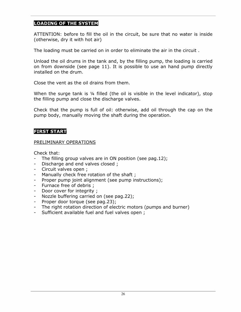
LOADING OF THE SYSTEM ATTENTION: before to fill the oil in the circuit, be sure that no water is inside (otherwise, dry it with hot air) The loading must be carried on in order to eliminate the air in the circuit . Unload the oil drums in the tank and, by the filling pump, the loading is carried on from downside (see page 11). It is possible to use an hand pump directly installed on the drum. Close the vent as the oil drains from them. When the surge tank is ¼ filled (the oil is visible in the level indicator), stop the filling pump and close the discharge valves. Check that the pump is full of oil: otherwise, add oil through the cap on the pump body, manually moving the shaft during the operation. FIRST START PRELIMINARY OPERATIONS Check that: - The filling group valves are in ON position (see pag.12); - Discharge and end valves closed ; - Circuit valves open ; - Manually check free rotation of the shaft ; - Proper pump joint alignment (see pump instructions); - Furnace free of debris ; - Door cover for integrity ; - Nozzle buffering carried on (see pag.22); - Proper door torque (see pag.23); - The right rotation direction of electric motors (pumps and burner) - Sufficient available fuel and fuel valves open ;

27
COLD START With system filled, start the circulation pump for two or three hours without start the burner During this period, open once a time the vents and, if installed, alternate the operation of the circulation pumps in order to eliminate air bubbles and impurities If the level in the surge tank is lowering (empty points of the circuit), replenish starting in the meantime the charge pump (fill oil in the surge tank only) Check flanges for leaks: tight the bolts if necessary Check leaks from welding : discharge the system to repair When the circulation is stabilized, the complete system filling is assured Turn off and clean the oil filter; Now a plant is ready to start. HOT START Reinstall the filter, Start the system Start the circulation pump , Start the burner at idle . The heating must be uniform, not more than 50 K/hour At 100°C, hold the temperature between 110° and 120° C up to stabilized circulation: the water evaporates. Open and close the vents several times to eliminate air and steam bubbles After stabilized circulation, increase the temperature 50°C/hour up to normal operations temperature Hold the operating temperature for some hours and check the system for leaks and other obvious damage and failure Take note of pressures, temperatures, instruments readings Check the inlet/outlet pressure difference of the oil, and compare it with technical data in order to verify the correct rigging of the pressure switch (page 14).

28
The burner operator shall adjust the burner at max power allowed by the boiler (see metallic plate) optimizing the combustion parameters. ALL THE PARAMETRS RECORDED AT FIRST START ARE VERY IMPORTANT TO EVALUATE THE FUTURE SYSTEM OPERATIONS Check tightness of the seals of the door, burner plate, cleaning doors, boiler/chimney fitting and torque (hot) to eliminate smoke leaks. Turn-off the burner, operating the pump up the oil temperature decreases below 150°C (automatic operations for our electric panels) Wait the oil cooling (< 50°C) and check the filter cleaning ATTENTION: - After the burner rigging, check that the flame does not contact the coil
bottom: the concrete could be damaged; - Check that the flame are centered in the furnace without contact the coil
walls : a cracking could occur and a subsequent coil failure - If oil leaks exist, turn-off the burner, wait oil cooling (< 50°C), discharge
the system and repair as necessary. Before to start the system, insulate the circuit Now a plant is ready to start. START AND SUBSEQUENT CHECKS For cold start, operate at reduced flame up to oil temp of 130 °C. Start always the circulation pump first and then the burner (mandatory condition on our electric panel). Check the manual valves of the circuit are fully open. Alternate periodically the operation of the circulation pumps (if 2nd pump available). If no check valves are present, close the valve on the turned-off pump delivery.

29
SYSTEM STOP
Every time the system is stopped, the circulation pump must be operated up to he oil temperature decreases at 150°C (automatic operations on our electric panels) MAINTENANCE
The scheduled maintenance is essential for the safety, the efficiency and duration of the generator. Before any maintenance operation - Wait the system cooling; - Turn-off electric power - Close fuel tapings Cleaning smoke side :
• Every 3 months if naphtha is used • Every 6 months if diesel is used • Every 12 months if gas is used
Before the cleaning, analyze the combustion and compare with the analysis after the cleaning. To clean the smoke side, operate as follows:
• Open the door and the cleaning door • Clean the coil and the cleaning door from the soot, using a high-pressure
water jet machine • Check the fuel system tightness; • Check smoke circuit tightness and replace worn seals if necessary;
Check the sealing of the fuel supply, particularly if the gaseous fuels are used. Check carefully that the circuit is smoke proof and, if necessary, replace the warn packing. The maintenance of the hydraulic circuit is carried out at the same time of the maintenance of the smoke side. Check periodically the alignment and the wear of the circulation pump joint Check the hydraulic circuit tightness and repair as necessary; Check the efficiency of the safety and control instruments;

30
Check the oil filter clogging (use the pressure gauges), and clean it, if necessary After you have terminated the maintenance and cleaning operations, repeat the start preliminary checks (see page 26), check the burner adjustment and analyze the smokes. DIATHERMIC OIL CHECK Periodically check the diathermic oil to monitor its characteristics. The life of the oil is about 20000 hours of operation, but it depends from the temperature and the proper system operations. (if the temperature is at the max limit foreseen for the oil, the life of the oil will be sensibly reduced). For the oil analysis, its sample and check frequency, refer to manufacturer instructions. Sample the oil from the proper outlet on the system. If the oil is completely deteriorated, change it. Do not mix new oil with the old one. After the system discharge, clean the lines if the oil was highly deteriorated: otherwise, the new oil will clean the system. To fill the new oil charge follow the instructions on page 26.
31
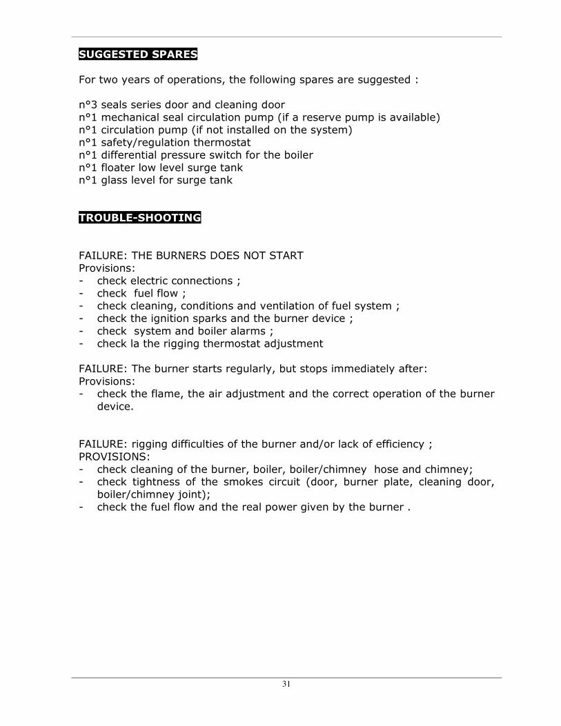
SUGGESTED SPARES For two years of operations, the following spares are suggested : n°3 seals series door and cleaning door n°1 mechanical seal circulation pump (if a reserve pump is available) n°1 circulation pump (if not installed on the system) n°1 safety/regulation thermostat n°1 differential pressure switch for the boiler n°1 floater low level surge tank n°1 glass level for surge tank TROUBLE-SHOOTING FAILURE: THE BURNERS DOES NOT START Provisions: - check electric connections ; - check fuel flow ; - check cleaning, conditions and ventilation of fuel system ; - check the ignition sparks and the burner device ; - check system and boiler alarms ; - check la the rigging thermostat adjustment FAILURE: The burner starts regularly, but stops immediately after: Provisions: - check the flame, the air adjustment and the correct operation of the burner
device. FAILURE: rigging difficulties of the burner and/or lack of efficiency ; PROVISIONS: - check cleaning of the burner, boiler, boiler/chimney hose and chimney; - check tightness of the smokes circuit (door, burner plate, cleaning door,
boiler/chimney joint); - check the fuel flow and the real power given by the burner .
32
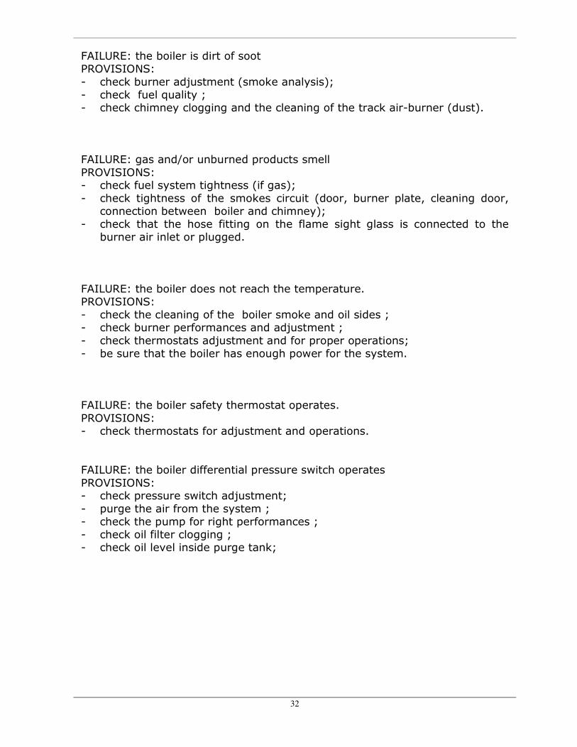
FAILURE: the boiler is dirt of soot PROVISIONS: - check burner adjustment (smoke analysis); - check fuel quality ; - check chimney clogging and the cleaning of the track air-burner (dust). FAILURE: gas and/or unburned products smell PROVISIONS: - check fuel system tightness (if gas); - check tightness of the smokes circuit (door, burner plate, cleaning door,
connection between boiler and chimney); - check that the hose fitting on the flame sight glass is connected to the
burner air inlet or plugged. FAILURE: the boiler does not reach the temperature. PROVISIONS: - check the cleaning of the boiler smoke and oil sides ; - check burner performances and adjustment ; - check thermostats adjustment and for proper operations; - be sure that the boiler has enough power for the system. FAILURE: the boiler safety thermostat operates. PROVISIONS: - check thermostats for adjustment and operations. FAILURE: the boiler differential pressure switch operates PROVISIONS: - check pressure switch adjustment; - purge the air from the system ; - check the pump for right performances ; - check oil filter clogging ; - check oil level inside purge tank;

33
FAILURE: surge tank low level alarm operates; PROVISIONS: - check oil leaks in the system; - check discharge valves are closed . FAILURE: surge tank high temperature alarm operates . PROVISIONS: - check la thermostat adjustment; - check the surge line for position on the system, dimensions and lay-out. - cool the surge line FAILURE: Oil filter pressure switch operates PROVISIONS: - check pressure switch adjustment - clean the filter FAILURE: mechanical noises, vibrations, circulation pump cavitations. PROVISIONS: - check joint alignment and bearings conditions ; - check circuit ventilation; - check the surge tank height ; FAILURE: circulation pump motor overheating (high stress). PROVISIONS: - check the motor electric load and the pump absorbed power ; - check the joint alignment; FAILURE: Oil lift-off from surge tank PROVISIONS: - check cold start initial level ; - check the surge tank capacity ; Ĩ

34