Embed Size (px)
Citation preview

Technical Memorandum 8
Existing Geometric Conditions Evaluation
March 2013

Technical Memorandum 8 – Existing Geometric Conditions Evaluation I-24 Multimodal Corridor Study March 2013 Page i
Technical Memorandum 8
Existing Geometric Conditions Evaluation
T h i s d o c u m e n t i s p o s t e d a t : http://www.tdot.state.tn.us/i24/
This document was prepared by Atkins for the
Tennessee Department of Transportation Project No. 99108-1154-04

Technical Memorandum 8 – Existing Geometric Conditions Evaluation I-24 Multimodal Corridor Study March 2013 Page ii
Table of Contents
1.0 Introduction .............................................................................................. 1
1.1 Corridor Location and Overview .............................................................................. 1
1.2 Purpose of This Document in the Study Process ...................................................... 1
2.0 Evaluation of Existing Geometric Conditions ............................................. 3
2.1 Data Compilation .................................................................................................... 3
2.2 Cross-Sectional Elements ........................................................................................ 3
2.3 Vertical Geometry .................................................................................................. 3
2.4 Horizontal Geometry ............................................................................................ 14
2.5 Bridge Condition ................................................................................................... 14
2.6 Pavement Condition ............................................................................................. 14
2.7 Potential Rockslides .............................................................................................. 18
2.8 Interchange Configuration .................................................................................... 18
Appendices Appendix A Definition of I-24 Corridor Segments
Appendix B Maps of I-24 Exits

Technical Memorandum 8 – Existing Geometric Conditions Evaluation I-24 Multimodal Corridor Study March 2013 Page iii
List of Figures
Figure 1.1: Study Corridor Map ...................................................................................................... 2
Figure 2.1: I-24 Corridor Segments - Montgomery and Robertson Counties ................................ 4
Figure 2.2: I-24 Corridor Segments - Robertson, Cheatham and Davidson Counties ................... 5
Figure 2.3: I-24 Corridor Segments - Davidson County ................................................................. 6
Figure 2.4: I-24 Corridor Segments - Davidson and Rutherford Counties ..................................... 7
Figure 2.5: I-24 Corridor Segments - Rutherford County .............................................................. 8
Figure 2.6: I-24 Corridor Segments - Rutherford, Bedford and Coffee Counties .......................... 9
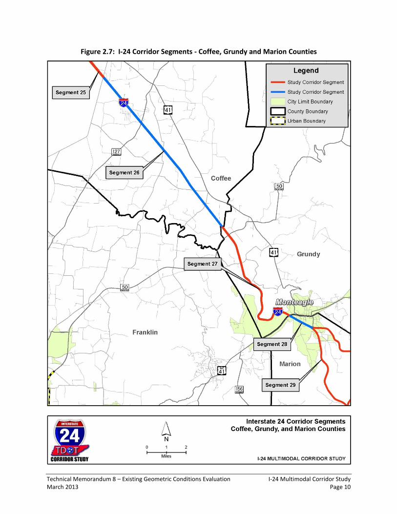
Figure 2.7: I-24 Corridor Segments - Coffee, Grundy and Marion Counties ............................... 10
Figure 2.8: I-24 Corridor Segments - Marion County ................................................................... 11
Figure 2.9: I-24 Corridor Segments - Marion and Hamilton Counties ......................................... 12
List of Tables
Table 2.1: Summary of Cross-Sectional Element Evaluation by I-24 Segment ............................ 13
Table 2.2: Summary of Vertical and Horizontal Geometry Evaluation by I-24 Segment ............ 15
Table 2.3: Summary of Bridge Condition Evaluation by I-24 Segment ........................................ 16
Table 2.4: Summary of Pavement Condition and Potential Rockslide Evaluation by I-24 Segment .......................................................................................................... 17
Table 2.5: Summary of Interchange Configuration Evaluation by I-24 Segment ........................ 19

Technical Memorandum 8 – Existing Geometric Conditions Evaluation I-24 Multimodal Corridor Study March 2013 Page 1
1.0 Introduction
1.1 Corridor Location and Overview
The purpose of the I-24 Multimodal Corridor Study is to examine potential multimodal transportation improvements that would address existing and emerging transportation system issues associated with this strategic corridor through central Tennessee connecting the Clarksville, Nashville and Chattanooga urban areas. The corridor extends from the Kentucky border to where it meets I-75 in Hamilton County, a distance of approximately 185 miles (refer to Figure 1.1). The analysis of corridor needs will go through a structured process of characterizing existing and projected corridor conditions, describing the purpose and need for corridor improvements, defining a set of performance measures against which to evaluate improvement options, and evaluating potential corridor improvements against these performance measures to develop a set of recommended improvements.
1.2 Purpose of This Document in the Study Process
The purpose of this document is to identify all locations along I-24 that do not meet the current standards for several geometric factors that include: cross-sectional elements, vertical geometry, horizontal geometry, bridge conditions, pavement conditions, and interchange configuration. This document also includes an analysis of potential rockslide locations. This analysis will be used later in the I-24 Multimodal Corridor Study when alternative improvement strategies and scenarios are developed and evaluated.

Technical Memorandum 8 – Existing Geometric Conditions Evaluation I-24 Multimodal Corridor Study March 2013 Page 2
Figure 1.1: Study Corridor Map
Technical Memorandum 8 – Existing Geometric Conditions Evaluation I-24 Multimodal Corridor Study March 2013 Page 3
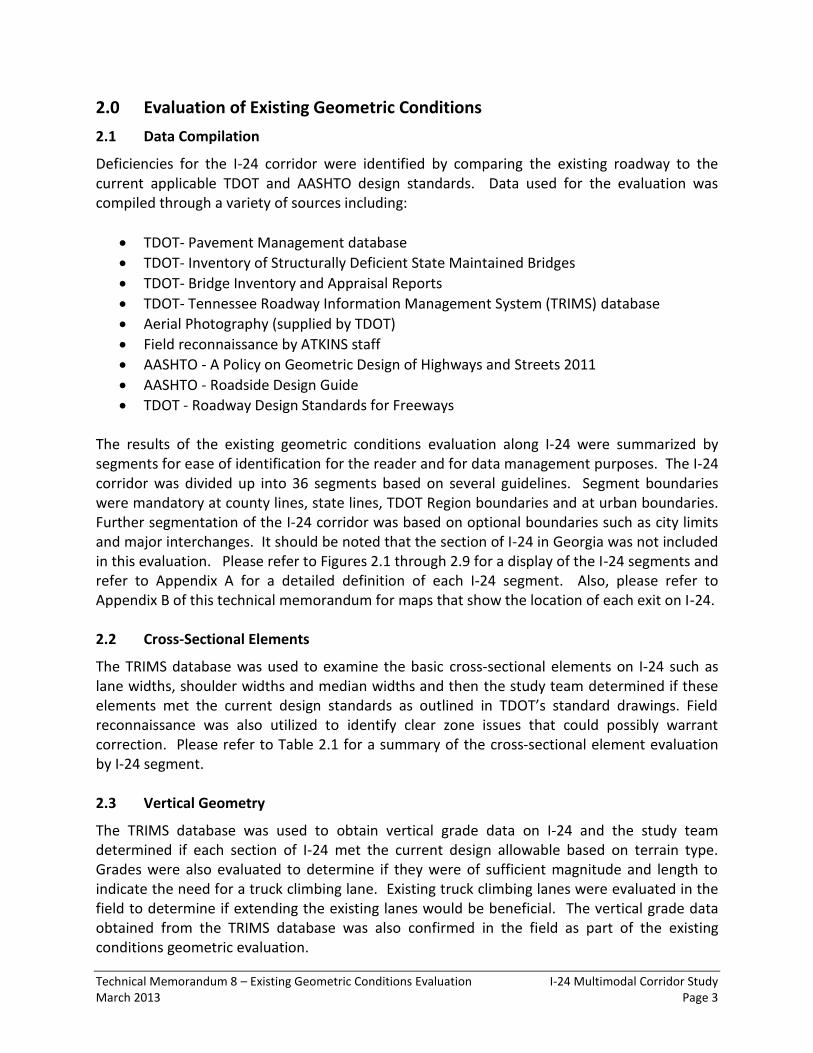
2.0 Evaluation of Existing Geometric Conditions
2.1 Data Compilation
Deficiencies for the I-24 corridor were identified by comparing the existing roadway to the current applicable TDOT and AASHTO design standards. Data used for the evaluation was compiled through a variety of sources including:
TDOT- Pavement Management database
TDOT- Inventory of Structurally Deficient State Maintained Bridges
TDOT- Bridge Inventory and Appraisal Reports
TDOT- Tennessee Roadway Information Management System (TRIMS) database
Aerial Photography (supplied by TDOT)
Field reconnaissance by ATKINS staff
AASHTO - A Policy on Geometric Design of Highways and Streets 2011
AASHTO - Roadside Design Guide
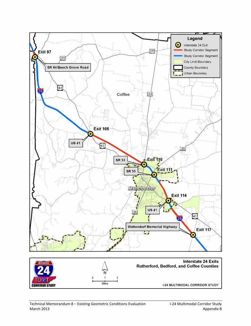
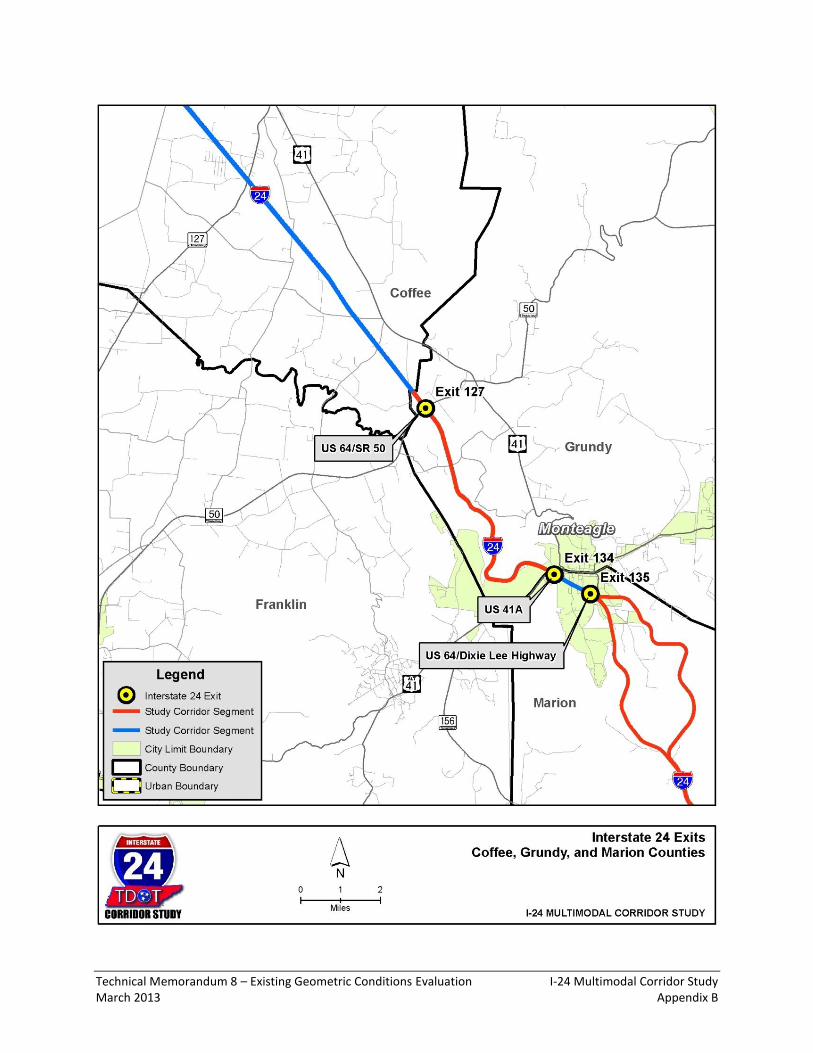
TDOT - Roadway Design Standards for Freeways The results of the existing geometric conditions evaluation along I-24 were summarized by segments for ease of identification for the reader and for data management purposes. The I-24 corridor was divided up into 36 segments based on several guidelines. Segment boundaries were mandatory at county lines, state lines, TDOT Region boundaries and at urban boundaries. Further segmentation of the I-24 corridor was based on optional boundaries such as city limits and major interchanges. It should be noted that the section of I-24 in Georgia was not included in this evaluation. Please refer to Figures 2.1 through 2.9 for a display of the I-24 segments and refer to Appendix A for a detailed definition of each I-24 segment. Also, please refer to Appendix B of this technical memorandum for maps that show the location of each exit on I-24. 2.2 Cross-Sectional Elements
The TRIMS database was used to examine the basic cross-sectional elements on I-24 such as lane widths, shoulder widths and median widths and then the study team determined if these elements met the current design standards as outlined in TDOT’s standard drawings. Field reconnaissance was also utilized to identify clear zone issues that could possibly warrant correction. Please refer to Table 2.1 for a summary of the cross-sectional element evaluation by I-24 segment. 2.3 Vertical Geometry
The TRIMS database was used to obtain vertical grade data on I-24 and the study team determined if each section of I-24 met the current design allowable based on terrain type. Grades were also evaluated to determine if they were of sufficient magnitude and length to indicate the need for a truck climbing lane. Existing truck climbing lanes were evaluated in the field to determine if extending the existing lanes would be beneficial. The vertical grade data obtained from the TRIMS database was also confirmed in the field as part of the existing conditions geometric evaluation.

Technical Memorandum 8 – Existing Geometric Conditions Evaluation I-24 Multimodal Corridor Study March 2013 Page 4
Figure 2.1: I-24 Corridor Segments - Montgomery and Robertson Counties

Technical Memorandum 8 – Existing Geometric Conditions Evaluation I-24 Multimodal Corridor Study March 2013 Page 5
Figure 2.2: I-24 Corridor Segments - Robertson, Cheatham and Davidson Counties

Technical Memorandum 8 – Existing Geometric Conditions Evaluation I-24 Multimodal Corridor Study March 2013 Page 6
Figure 2.3: I-24 Corridor Segments - Davidson County

Technical Memorandum 8 – Existing Geometric Conditions Evaluation I-24 Multimodal Corridor Study March 2013 Page 7
Figure 2.4: I-24 Corridor Segments - Davidson and Rutherford Counties

Technical Memorandum 8 – Existing Geometric Conditions Evaluation I-24 Multimodal Corridor Study March 2013 Page 8
Figure 2.5: I-24 Corridor Segments - Rutherford County

Technical Memorandum 8 – Existing Geometric Conditions Evaluation I-24 Multimodal Corridor Study March 2013 Page 9
Figure 2.6: I-24 Corridor Segments - Rutherford, Bedford and Coffee Counties
Technical Memorandum 8 – Existing Geometric Conditions Evaluation I-24 Multimodal Corridor Study March 2013 Page 10
Figure 2.7: I-24 Corridor Segments - Coffee, Grundy and Marion Counties

Technical Memorandum 8 – Existing Geometric Conditions Evaluation I-24 Multimodal Corridor Study March 2013 Page 11
Figure 2.8: I-24 Corridor Segments - Marion County

Technical Memorandum 8 – Existing Geometric Conditions Evaluation I-24 Multimodal Corridor Study March 2013 Page 12
Figure 2.9: I-24 Corridor Segments - Marion and Hamilton Counties

Technical Memorandum 8 – Existing Geometric Conditions Evaluation I-24 Multimodal Corridor Study March 2013 Page 13
Substandard
Shoulder
Substandard Lane
Widths
Substandard
Median
Substandard Clear
Zone
(Impacted Log
Miles)
(Impacted Log
Miles)
(Impacted Log
Miles)
(Impacted Log
Miles)
1 Montgomery 1
2 Montgomery 1
3 Montgomery 3
4 Robertson
5 Cheatham
6 Robertson
7 Cheatham
8 Davidson
9 Davidson
10 Davidson 1
11 Davidson 1 1
12 Davidson 1
13 Davidson 1
14 Rutherford 1
15 Rutherford 1 1
16 Rutherford 1
17 Rutherford
18 Rutherford
19 Bedford
20 Coffee
21 Coffee
22 Coffee
23 Coffee 1
24 Coffee 2
25 Coffee
26 Coffee 1
27 Grundy 1 1 1
28 Marion 1
29 Marion 1
30 Marion 1
31 Marion 1
32 Marion 1
33 Marion 1 1
34 Hamilton
35 Hamilton 1
36 Hamilton 1 1 1
Totals 16 0 4 12
CountyI-24 Segment
Table 2.1: Summary of Cross-Sectional Element Evaluation by I-24 Segment
Note: Impacted Log Miles = Number of whole directional log miles with one or more deficiencies.

Technical Memorandum 8 – Existing Geometric Conditions Evaluation I-24 Multimodal Corridor Study March 2013 Page 14
The TRIMS database was used to identify portions of the roadway with grades of steeper than 3%. These grades in conjunction with design speed and type of terrain were compared to the allowable values in Table 8-1 of AASHTO’s A Policy on Geometric Design of Highways and Streets 2011 to determine if a deficiency existed. Please refer to Table 2.2 for a summary of the vertical geometry evaluation by I-24 segment. 2.4 Horizontal Geometry
Horizontal curvature of the roadway in addition to superelevation transition lengths were evaluated based on an appropriate design speed for the current posted speed. Checking actual superelevation rates was not practical, so the distance between successive curves were compared to TDOT standards to confirm that required transitions were possible. Please refer to Table 2.2 for a summary of the horizontal geometry evaluation by I-24 segment. 2.5 Bridge Condition
Data on bridge conditions was gathered using TDOT’s Inventory of Structurally Deficient State Maintained Bridges and Bridge Inventory and Appraisal Reports. Bridges listed on the Structurally Deficient list or any bridge with a sufficiency rating of less than 50, which would qualify them for replacement, were identified as deficient. In addition, bridges with a Sufficiency Rating of greater than 50 and less than 75, making them a candidate for either replacement or major rehabilitation if widened, were identified to assist in the future identification of projects. Some bridges have railings which may not be NCHRP-350 compliant. These structures were also identified and listed as deficient. Bridge Inventory and Appraisal Reports and field inspections were also used to identify any structures with deficient horizontal or vertical clearances and also if they could accommodate any future widening. Deficiencies were identified as vertical clearances that were less than 16.0 feet for I-24 mainline sections and ramps, 21.5 feet for railroads, and 14.5 feet for all other non-interstate roadways. Please refer to Table 2.3 for a summary of the bridge condition evaluation by I-24 segment. 2.6 Pavement Condition
Data on pavement condition for the roadway was obtained through TDOT’s Pavement Management Section of the Materials and Tests Division. Using the recommendation of the Department’s personnel, sections of the roadway with a Pavement Quality Index (PQI) of 3.5 or less were identified as deficient and in need of rehabilitation. A field review determined that the overall pavement condition on I-24 seemed in good condition and was consistent with the evaluation completed by TDOT’s Pavement Management Section. Please refer to Table 2.4 for a summary of the pavement condition evaluation by I-24 segment.

Technical Memorandum 8 – Existing Geometric Conditions Evaluation I-24 Multimodal Corridor Study March 2013 Page 15
Substandard
Horizontal
Alignment
Substandard
Vertical Alignment
Proposed
Extension of
Existing Truck
Lanes
Proposed New
Truck Lanes(Impacted Log
Miles)
(Impacted Log
Miles)
(Impacted Log
Miles)
(Impacted Log
Miles)
1 Montgomery 2
2 Montgomery 2
3 Montgomery 1
4 Robertson
5 Cheatham
6 Robertson
7 Cheatham 1 2
8 Davidson 2
9 Davidson 2
10 Davidson
11 Davidson
12 Davidson
13 Davidson 1
14 Rutherford 2
15 Rutherford
16 Rutherford
17 Rutherford
18 Rutherford
19 Bedford
20 Coffee 1
21 Coffee 6
22 Coffee
23 Coffee
24 Coffee
25 Coffee
26 Coffee
27 Grundy 1 6
28 Marion
29 Marion 1 1
30 Marion
31 Marion 4
32 Marion 4
33 Marion 1
34 Hamilton 1
35 Hamilton 2
36 Hamilton 2
Totals 6 27 2 10
CountyI-24 Segment
Table 2.2: Summary of Vertical and Horizontal Geometry Evaluation by I-24 Segment
Note: Impacted Log Miles = Number of whole directional log miles with one or more deficiencies or occurrences.

Technical Memorandum 8 – Existing Geometric Conditions Evaluation I-24 Multimodal Corridor Study March 2013 Page 16
Bridge Contition
Sufficiency Rating
< 50
Bridge Condition
Sufficiency Rating
Between 50 - 75
Bridge Condition
Structurally
Deficient
Bridge Rail
Condition Deficient
Locations
Bridge Does Not
Allow I-24
Widening
Substandard
Bridge Width
Substandard
Vertical Bridge
Clearance
(Each) (Each) (Each) (Each) (Each) (Each) (Each)
1 Montgomery 2
2 Montgomery 3
3 Montgomery 1
4 Robertson 1 1
5 Cheatham
6 Robertson 1
7 Cheatham 1 1
8 Davidson 1 1 2
9 Davidson 7 1 3 2
10 Davidson 2 1 4 1
11 Davidson 6 1 6 2
12 Davidson 2 1 3 1 1
13 Davidson 7 2 1
14 Rutherford 5 1
15 Rutherford
16 Rutherford 1 2
17 Rutherford
18 Rutherford 1
19 Bedford
20 Coffee 7 4
21 Coffee
22 Coffee 1
23 Coffee
24 Coffee
25 Coffee
26 Coffee
27 Grundy 1
28 Marion 1 4 1
29 Marion 1
30 Marion
31 Marion 1
32 Marion 2 2
33 Marion
34 Hamilton
35 Hamilton 6 1 1
36 Hamilton 5 10 2
Totals 1 61 5 21 27 3 11
I-24 Segment County
Table 2.3: Summary of Bridge Condition Evaluation by I-24 Segment

Technical Memorandum 8 – Existing Geometric Conditions Evaluation I-24 Multimodal Corridor Study March 2013 Page 17
Pavement
Condition
PQI < 3.5
Potential Rock
Slide Areas
(Impacted Log
Miles)
(Impacted Log
Miles)
1 Montgomery
2 Montgomery
3 Montgomery
4 Robertson
5 Cheatham
6 Robertson 1
7 Cheatham 2 1
8 Davidson
9 Davidson 5
10 Davidson 2
11 Davidson 1 2
12 Davidson 4
13 Davidson 1 1
14 Rutherford
15 Rutherford 1 1
16 Rutherford
17 Rutherford
18 Rutherford 2
19 Bedford 2
20 Coffee 2
21 Coffee
22 Coffee
23 Coffee
24 Coffee
25 Coffee
26 Coffee
27 Grundy 1
28 Marion 1
29 Marion 1 4
30 Marion 2 3
31 Marion 2
32 Marion 1
33 Marion 1
34 Hamilton
35 Hamilton 2
36 Hamilton 2
Totals 22 26
CountyI-24 Segment
Table 2.4: Summary of Pavement Condition and Potential Rockslide Evaluation by I-24 Segment
Note: Impacted Log Miles = Number of whole directional log miles with one or more deficiencies or occurrences.

Technical Memorandum 8 – Existing Geometric Conditions Evaluation I-24 Multimodal Corridor Study March 2013 Page 18
2.7 Potential Rockslides
Rock cuts that were of sufficient height and in close enough proximity to I-24 to pose a threat to traffic if a slide occurred were evaluated in the field. Potential slide locations were identified by areas that either 1) showed signs of recent failures that could threaten traffic, 2) showed noticeable erosion of the soil surrounding the rock cut, 3) included a cut that contained layers of “weathering shale” that showed signs of noticeable deterioration, or 4) previously repaired areas where the repair showed signs of deterioration. It should be noted that the roadway between US-64/Dixie Lee Highway (exit 135) and SR-2/Battle Creek Road (exit 143) had several previously repaired areas that showed significant deterioration. Please refer to Table 2.4 for a summary of the potential rockslide evaluation by I-24 segment. 2.8 Interchange Configuration
Interchanges along the I-24 Corridor were examined to determine if they met the current standards and guidelines for a variety of characteristics. If any element of the interchange design violated current standards or good design practice it was identified as deficient. The interchanges were evaluated for the following elements:
Overall spacing (1 mile urban, 2 miles rural)
Ramp spacing (Based on Figure 10-68 of AASHTO - A Policy on Geometric Design of
Highways and Streets 2011)
Ramp lengths and ramp design speed (Based on Tables 10-3 and 10-5 of AASHTO - A
Policy on Geometric Design of Highways and Streets 2011)
Coordination of lane balance and basic number of lanes. (Based on Figures 10-50 and
10-51 of AASHTO - A Policy on Geometric Design of Highways and Streets 2011)
Weaving section lengths
Uniformity of Interchange Patterns. Interchanges were analyzed as a group and
inconsistencies such as non-uniform entrance and exit ramp patterns, left hand exits
and ramp patterns that prohibit proper signage were identified.
It should be noted that the primary issue with the interchange configurations evaluation involved substandard ramp lengths. Please refer to Table 2.5 for a summary of the interchange configuration evaluation by I-24 segment.

Technical Memorandum 8 – Existing Geometric Conditions Evaluation I-24 Multimodal Corridor Study March 2013 Page 19
Substandard Ramp
Length or
Geometry
Substandard Ramp
Spacing or
Weaving Section
Substandard
Interchange
Spacing
Improper Lane
Balance
Interchange
Uniformity
Violation
(Each) (Each) (Each) (Each) (Each)
1 Montgomery
2 Montgomery
3 Montgomery
4 Robertson
5 Cheatham
6 Robertson
7 Cheatham
8 Davidson
9 Davidson
10 Davidson 2 1 1
11 Davidson 1 1 3 4
12 Davidson 3 1 12 1
13 Davidson 6 1 2
14 Rutherford 1 2
15 Rutherford 2 1 1
16 Rutherford 2
17 Rutherford 2 1
18 Rutherford
19 Bedford
20 Coffee 1
21 Coffee 3
22 Coffee 4 1
23 Coffee
24 Coffee 5
25 Coffee 6
26 Coffee 1
27 Grundy 6 1
28 Marion 2 1
29 Marion
30 Marion 3
31 Marion 1 1
32 Marion 9 1
33 Marion
34 Hamilton
35 Hamilton 3 2 2
36 Hamilton 6 1 4 1
Totals 62 8 11 15 20
CountyI-24 Segment
Table 2.5: Summary of Interchange Configuration Evaluation by I-24 Segment

Technical Memorandum 8 – Existing Geometric Conditions Evaluation I-24 Multimodal Corridor Study March 2013 Appendix A
Appendix A Definition of I-24 Corridor Segments

Technical Memorandum 8 – Existing Geometric Conditions Evaluation I-24 Multimodal Corridor Study March 2013 Appendix A
I-24 Segment TDOT Region
TN
County
Number
TN
County Name
Beginning
Mile Log
(by County)
Ending
Mile Log
(by County)
Segment
Distance
TRIMS
env_Type TRIMS beginning description TRIMS ending description
1 3 63 MONTGOMERY 0.000 4.410 4.410 URBAN KENTUCKY-TENNESSEE STATE LINE SR-13 WILMA RUDOLPH BLVD. / CENTER OF OVERHEAD
2 3 63 MONTGOMERY 4.410 11.033 6.623 URBAN SR-13 WILMA RUDOLPH BLVD. / CENTER OF OVERHEAD LEAVE CLARKSVILLE CITY LIMITS
3 3 63 MONTGOMERY 11.033 17.200 6.167 RURAL LEAVE CLARKSVILLE CITY LIMITS MONTGOMERY-ROBERTSON COUNTY LINE
4 3 74 ROBERTSON 0.000 8.120 8.120 RURAL MONTGOMERY-ROBERTSON COUNTY LINE ROBERTSON-CHEATHAM COUNTY LINE
5 3 11 CHEATHAM 0.000 0.700 0.700 RURAL ROBERTSON-CHEATHAM COUNTY LINE CHEATHAM-ROBERTSON COUNTY LINE
6 3 74 ROBERTSON 0.000 2.330 2.330 RURAL CHEATHAM-ROBERTSON COUNTY LINE ROBERTSON-CHEATHAM COUNTY LINE
7 3 11 CHEATHAM 0.000 3.630 3.630 RURAL ROBERTSON-CHEATHAM COUNTY LINE CHEATHAM-DAVIDSON COUNTY LINE
8 3 19 DAVIDSON 0.000 3.000 3.000 RURAL CHEATHAM-DAVIDSON COUNTY LINE SR-65 WHITES CREEK PK. / CENTER OF OVERHEAD
9 3 19 DAVIDSON 3.000 10.822 7.822 RURAL SR-65 WHITES CREEK PK. / CENTER OF OVERHEAD ENTER NASHVILLE URBAN BOUNDARY
10 3 19 DAVIDSON 10.822 12.990 2.168 URBAN ENTER NASHVILLE URBAN BOUNDARY I-65 SB LNS. RT. & LT.
11 3 19 DAVIDSON 12.990 16.060 3.070 URBAN I-65 SB LNS. RT. & LT. I-40 EB LNS. RT. & LT.
12 3 19 DAVIDSON 16.060 20.323 4.263 URBAN I-40 EB LNS. RT. & LT. SR-255 HARDING PL. / CENTER OF UNDERPASS
13 3 19 DAVIDSON 20.323 27.810 7.487 URBAN SR-255 HARDING PL. / CENTER OF UNDERPASS DAVIDSON-RUTHERFORD COUNTY LINE
14 3 75 RUTHERFORD 0.000 6.784 6.784 URBAN DAVIDSON-RUTHERFORD COUNTY LINE ENTER SMYRNA CITY LIMITS
15 3 75 RUTHERFORD 6.784 12.109 5.325 URBAN ENTER SMYRNA CITY LIMITS ENTER MURFREESBORO CITY LIMITS
16 3 75 RUTHERFORD 12.109 18.170 6.061 URBAN ENTER MURFREESBORO CITY LIMITS UNDERPASS [75I00240029]: SR-10 S. CHURCH ST.
17 3 75 RUTHERFORD 18.170 27.302 9.132 URBAN UNDERPASS [75I00240029]: SR-10 S. CHURCH ST. LEAVE NASHVILLE URBAN BOUNDARY
18 3 75 RUTHERFORD 27.302 33.290 5.988 RURAL LEAVE NASHVILLE URBAN BOUNDARY RUTHERFORD-BEDFORD COUNTY LINE
19 3 2 BEDFORD 0.000 0.450 0.450 RURAL RUTHERFORD-BEDFORD COUNTY LINE BEDFORD-COFFEE COUNTY LINE
20 2 16 COFFEE 0.000 8.420 8.420 RURAL BEDFORD-COFFEE COUNTY LINE SR-2 MURFREESBORO HWY. / CENTER OF UNDERPASS
21 2 16 COFFEE 8.420 13.137 4.717 RURAL SR-2 MURFREESBORO HWY. / CENTER OF UNDERPASS ENTER MANCHESTER CITY LIMITS
22 2 16 COFFEE 13.137 15.328 2.191 URBAN ENTER MANCHESTER CITY LIMITS LEAVE MANCHESTER URBAN BOUNDARY
23 2 16 COFFEE 15.328 16.828 1.500 RURAL LEAVE MANCHESTER URBAN BOUNDARY ENTER MANCHESTER URBAN BOUNDARY
24 2 16 COFFEE 16.828 17.601 0.773 URBAN ENTER MANCHESTER URBAN BOUNDARY LEAVE MANCHESTER CITY LIMITS & URBAN BOUNDARY
25 2 16 COFFEE 17.601 20.400 2.799 RURAL LEAVE MANCHESTER CITY LIMITS & URBAN BOUNDARY UNDERPASS [16I00240039]: 0918 ARNOLD CENTER RD.
26 2 16 COFFEE 20.400 30.160 9.760 RURAL UNDERPASS [16I00240039]: 0918 ARNOLD CENTER RD. COFFEE-GRUNDY COUNTY LINE
27 2 31 GRUNDY 0.000 7.310 7.310 RURAL COFFEE-GRUNDY COUNTY LINE GRUNDY-MARION COUNTY LINE
28 2 58 MARION 0.000 1.380 1.380 RURAL GRUNDY-MARION COUNTY LINE SR-2 DIXIE LEE AVE. / CENTER OF UNDERPASS
29 2 58 MARION 1.380 8.360 6.980 RURAL SR-2 DIXIE LEE AVE. / CENTER OF UNDERPASS SR-2 BATTLE CREEK RD. / CENTER OF UNDERPASS
30 2 58 MARION 8.360 16.073 7.713 RURAL SR-2 BATTLE CREEK RD. / CENTER OF UNDERPASS ENTER KIMBALL CITY LIMITS
31 2 58 MARION 16.073 21.354 5.281 RURAL ENTER KIMBALL CITY LIMITS LEAVE JASPER CITY LIMITS
32 2 58 MARION 21.354 26.810 5.456 RURAL LEAVE JASPER CITY LIMITS SR-156 STATE HWY. 156 / CENTER OF UNDERPASS
33 2 58 MARION 26.810 32.130 5.320 RURAL SR-156 STATE HWY. 156 / CENTER OF UNDERPASS MARION-HAMILTON COUNTY LINE
34 2 33 HAMILTON 0.000 0.310 0.310 RURAL MARION-HAMILTON COUNTY LINE TENNESSEE-GEORGIA STATE LINE
35 2 33 HAMILTON 0.000 7.520 7.520 URBAN TENNESSEE-GEORGIA STATE LINE OVERHEAD [33I00240015]: I-124 US-27 NB LNS. / RT. LNS. ONLY
36 2 33 HAMILTON 7.520 14.710 7.190 URBAN OVERHEAD [33I00240015]: I-124 US-27 NB LNS. / RT. LNS. ONLY I-75 US-74 NB LNS. RT. & LT.
I-24 Corridor Segments

Technical Memorandum 8 – Existing Geometric Conditions Evaluation I-24 Multimodal Corridor Study March 2013 Appendix B
Appendix B Maps of I-24 Exits

Technical Memorandum 8 – Existing Geometric Conditions Evaluation I-24 Multimodal Corridor Study March 2013 Appendix B

Technical Memorandum 8 – Existing Geometric Conditions Evaluation I-24 Multimodal Corridor Study March 2013 Appendix B

Technical Memorandum 8 – Existing Geometric Conditions Evaluation I-24 Multimodal Corridor Study March 2013 Appendix B

Technical Memorandum 8 – Existing Geometric Conditions Evaluation I-24 Multimodal Corridor Study March 2013 Appendix B

Technical Memorandum 8 – Existing Geometric Conditions Evaluation I-24 Multimodal Corridor Study March 2013 Appendix B

Technical Memorandum 8 – Existing Geometric Conditions Evaluation I-24 Multimodal Corridor Study March 2013 Appendix B
Technical Memorandum 8 – Existing Geometric Conditions Evaluation I-24 Multimodal Corridor Study March 2013 Appendix B
Technical Memorandum 8 – Existing Geometric Conditions Evaluation I-24 Multimodal Corridor Study March 2013 Appendix B

Technical Memorandum 8 – Existing Geometric Conditions Evaluation I-24 Multimodal Corridor Study March 2013 Appendix B

Technical Memorandum 8 – Existing Geometric Conditions Evaluation I-24 Multimodal Corridor Study March 2013 Appendix B

Technical Memorandum 8 – Existing Geometric Conditions Evaluation I-24 Multimodal Corridor Study March 2013 Appendix B

Technical Memorandum 8 – Existing Geometric Conditions Evaluation I-24 Multimodal Corridor Study March 2013 Appendix B