Embed Size (px)
Citation preview
Page 1 of 15
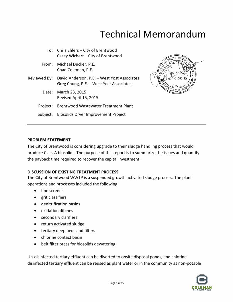
Technical Memorandum
To: Chris Ehlers – City of Brentwood Casey Wichert – City of Brentwood
From: Michael Ducker, P.E. Chad Coleman, P.E.
Reviewed By: David Anderson, P.E. – West Yost Associates Greg Chung, P.E. – West Yost Associates
Date: March 23, 2015 Revised April 15, 2015
Project: Brentwood Wastewater Treatment Plant
Subject: Biosolids Dryer Improvement Project PROBLEM STATEMENT The City of Brentwood is considering upgrade to their sludge handling process that would produce Class A biosolids. The purpose of this report is to summarize the issues and quantify the payback time required to recover the capital investment. DISCUSSION OF EXISTING TREATMENT PROCESS The City of Brentwood WWTP is a suspended growth activated sludge process. The plant operations and processes included the following:
• fine screens • grit classifiers • denitrification basins • oxidation ditches • secondary clarifiers • return activated sludge • tertiary deep bed sand filters • chlorine contact basin • belt filter press for biosolids dewatering
Un-disinfected tertiary effluent can be diverted to onsite disposal ponds, and chlorine disinfected tertiary effluent can be reused as plant water or in the community as non-potable
Page 2 of 15
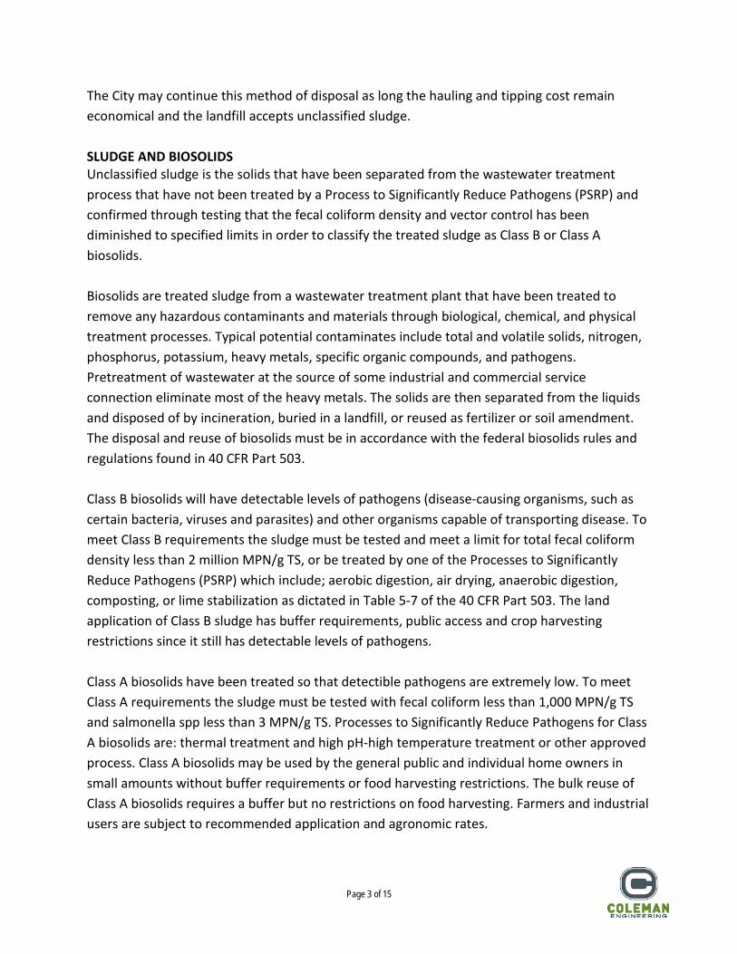
water. The remaining tertiary disinfected effluent flows over a cascade aerator prior to discharge into Marsh Creek. The solids handling facility receives waste activated sludge (WAS) and scum (SCUM) from the secondary clarifiers. The sludge is dewatered using a belt filter press before hauling offsite to a local landfill. Sludge filtrate is returned back to the headworks prior to the Parshall flume influent flow meter. The solids handling facilities are located in a two story building that is shared with plant headworks facilities. The belt filter presses are located on the upper level and are fed by sludge pumps located on the first level directly below. Dewatered sludge from the presses travels via conveyors across the second story and drops through the floor into a multiport conveyors that fill truck trailers in a dual bay truck loading dock on the first floor. The foul air handling units are located on the second floor and pump foul air to nearby soil bio-filters. The solids handling building has been sized to include equipment space and piping connection points for both the existing phase 1 and future phase 2 expansion of the WWTP. Table 1 below is a summary of the existing and planned future facilities. Table 1 – Sludge Dewatering Facilities
Equipment Existing Future
Sludge Pumps 2 duty, 1 standby 1 future
Belt Filter Press 2 duty 2 future
Hydraulic Power Units 2 duty 2 future
Polymer Feed Pumps 2 duty, 1 standby 1 future
Polymer Mixing Totes 2 duty 1 future
Foul Air Headers 2 duty 2 future
The sludge sent to the belt filter press comes directly from the secondary clarifiers without any additional aerobic or anaerobic digestion process. The oxidation ditch has a mean cell residence time of approximately 14 days. Polymer is added to the WAS and SCUM as a coagulant. The belt filter press produces a sludge with 15% solids, has no apparent odor or vector attraction. The belt filter press produces a dewatered and unclassified sludge that is currently being off-hauled to the Altamont Landfill (a Class 3 landfill) where it is used as alternative daily cover material.
Page 3 of 15
The City may continue this method of disposal as long the hauling and tipping cost remain economical and the landfill accepts unclassified sludge. SLUDGE AND BIOSOLIDS Unclassified sludge is the solids that have been separated from the wastewater treatment process that have not been treated by a Process to Significantly Reduce Pathogens (PSRP) and confirmed through testing that the fecal coliform density and vector control has been diminished to specified limits in order to classify the treated sludge as Class B or Class A biosolids. Biosolids are treated sludge from a wastewater treatment plant that have been treated to remove any hazardous contaminants and materials through biological, chemical, and physical treatment processes. Typical potential contaminates include total and volatile solids, nitrogen, phosphorus, potassium, heavy metals, specific organic compounds, and pathogens. Pretreatment of wastewater at the source of some industrial and commercial service connection eliminate most of the heavy metals. The solids are then separated from the liquids and disposed of by incineration, buried in a landfill, or reused as fertilizer or soil amendment. The disposal and reuse of biosolids must be in accordance with the federal biosolids rules and regulations found in 40 CFR Part 503. Class B biosolids will have detectable levels of pathogens (disease-causing organisms, such as certain bacteria, viruses and parasites) and other organisms capable of transporting disease. To meet Class B requirements the sludge must be tested and meet a limit for total fecal coliform density less than 2 million MPN/g TS, or be treated by one of the Processes to Significantly Reduce Pathogens (PSRP) which include; aerobic digestion, air drying, anaerobic digestion, composting, or lime stabilization as dictated in Table 5-7 of the 40 CFR Part 503. The land application of Class B sludge has buffer requirements, public access and crop harvesting restrictions since it still has detectable levels of pathogens. Class A biosolids have been treated so that detectible pathogens are extremely low. To meet Class A requirements the sludge must be tested with fecal coliform less than 1,000 MPN/g TS and salmonella spp less than 3 MPN/g TS. Processes to Significantly Reduce Pathogens for Class A biosolids are: thermal treatment and high pH-high temperature treatment or other approved process. Class A biosolids may be used by the general public and individual home owners in small amounts without buffer requirements or food harvesting restrictions. The bulk reuse of Class A biosolids requires a buffer but no restrictions on food harvesting. Farmers and industrial users are subject to recommended application and agronomic rates.

Page 4 of 15
SLUDGE TREATMENT Federal restrictions for sludge disposal are predominately on heavy metals, pathogens, and vector control. In general, heavy metal concentrations in WWTP influent has decreased due to the recent pretreatment requirements set upon commercial and industrial service connections. If disposal restrictions increase, the City could haul the waste to a Class 2 or Class 1 landfill at what would probably be a higher hauling cost and disposal fee. The City has performed a series of tests to determine if the existing “unclassified” dewatered sludge meets Class B limits for 2 million MPN/mg TS. The sludge does not meet Class B limits, but could be treated by one of the following processes to significantly reduce pathogens: aerobic digester, anaerobic digester, air drying, composting, or lime stabilization prior to disposal at a Class 1 or 2 landfill. Operations staff at the City of Brentwood WWTP are considering the costs of producing Class A biosolids as a way to reduce operating costs. Rather than spend resources in constructing a two part Class B and Class A solids handling facility the City would prefer to skip the Class B treatment process (digesters and etc.) and construct a Class A biosolids facility. EQUIPMENT The City of Brentwood is researching a screw type thermal dryer to produce Class A biosolids from unclassified sludge without having to first make a Class B biosolids. BIOSOLIDS THERMAL DRYER A screw type dryer is an enclosed trough with two internal screw conveyors that mix and move dewatered sludge at 15% solids from the wet sludge inlet hopper to the dry, 95% solids, biosolids outlet at the far end. The sludge is heated indirectly by thermal fluid that is circulated through the hollow screw blades and shafts, and through tubing in the insulated outer jacket. In some units auxiliary heating is applied by electrical heating elements. The sludge is mixed and heated to a minimum temperature and retained for a minimum time as required to produce Class A biosolid per 40 CFR Part 503. The internal screws are turned by a small electric motor and gearbox. The thermal fluid is heated by a separate heating unit equipped with a natural gas burner. Heated sludge from the dryer is sent through a condenser and cooling unit before being conveyed to storage or loading bay. Air handling units may be used to pull, dust, vapor, and odors for treatment. Excess water that is removed from the sludge is drained back to the WWTP headworks for retreatment. The screw type dryer systems were originally designed for the larger mining and paper pulp industries and have been modified to fit the municipal wastewater treatment market. The dryers tend to be very robust units with slow moving parts that have high wear resistance and relatively low horsepower requirements.
Page 5 of 15
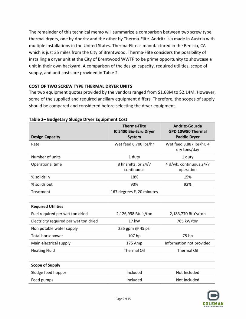
The remainder of this technical memo will summarize a comparison between two screw type thermal dryers, one by Andritz and the other by Therma-Flite. Andritz is a made in Austria with multiple installations in the United States. Therma-Flite is manufactured in the Benicia, CA which is just 35 miles from the City of Brentwood. Therma-Flite considers the possibility of installing a dryer unit at the City of Brentwood WWTP to be prime opportunity to showcase a unit in their own backyard. A comparison of the design capacity, required utilities, scope of supply, and unit costs are provided in Table 2. COST OF TWO SCREW TYPE THERMAL DRYER UNITS The two equipment quotes provided by the vendors ranged from $1.68M to $2.14M. However, some of the supplied and required ancillary equipment differs. Therefore, the scopes of supply should be compared and considered before selecting the dryer equipment. Table 2– Budgetary Sludge Dryer Equipment Cost
Design Capacity
Therma-Flite IC 5400 Bio-Scru Dryer
System
Andritz-Gourda GPD 10W80 Thermal
Paddle Dryer
Rate Wet feed 6,700 lbs/hr Wet feed 3,887 lbs/hr, 4 dry tons/day
Number of units 1 duty 1 duty
Operational time 8 hr shifts, or 24/7 continuous
4 d/wk, continuous 24/7 operation
% solids in 18% 15%
% solids out 90% 92%
Treatment 167 degrees F, 20 minutes
Required Utilities
Fuel required per wet ton dried 2,126,998 Btu’s/ton 2,183,770 Btu’s/ton
Electricity required per wet ton dried 17 kW 765 kW/ton
Non potable water supply 235 gpm @ 45 psi
Total horsepower 107 hp 75 hp
Main electrical supply 175 Amp Information not provided
Heating Fluid Thermal Oil Thermal Oil
Scope of Supply
Sludge feed hopper Included Not Included
Feed pumps Included Not Included
Page 6 of 15
Design Capacity
Therma-Flite IC 5400 Bio-Scru Dryer
System
Andritz-Gourda GPD 10W80 Thermal
Paddle Dryer
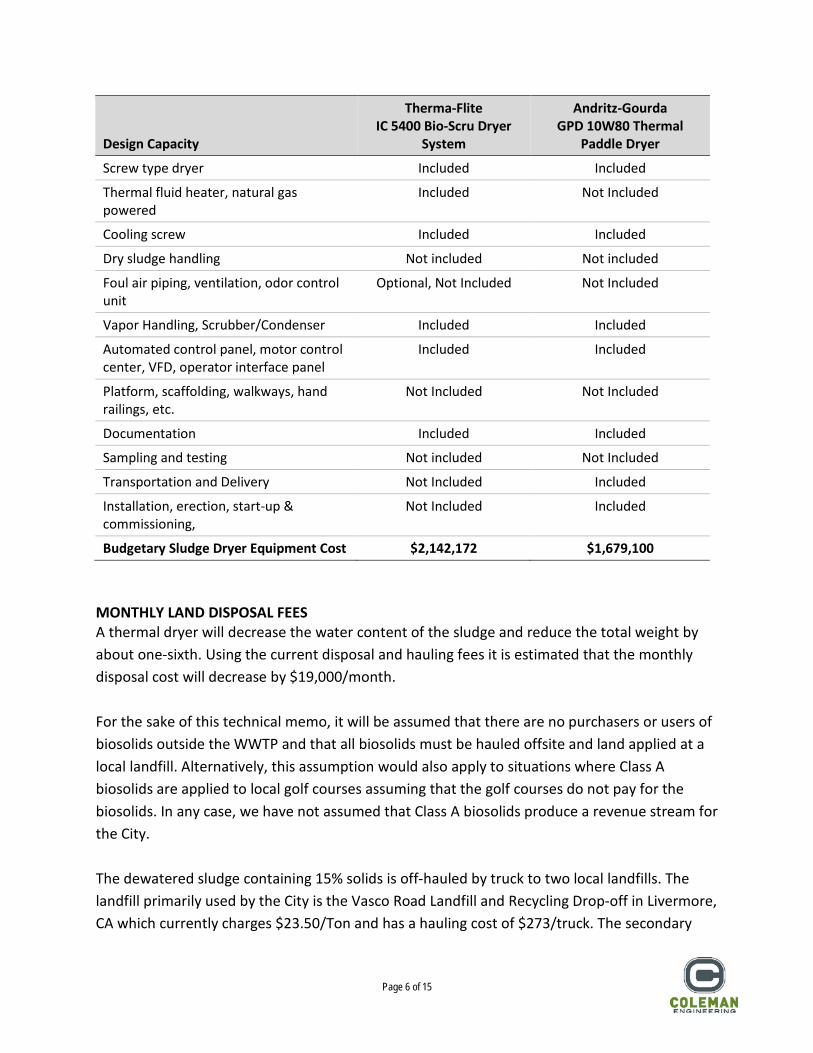
Screw type dryer Included Included
Thermal fluid heater, natural gas powered
Included Not Included
Cooling screw Included Included
Dry sludge handling Not included Not included
Foul air piping, ventilation, odor control unit
Optional, Not Included Not Included
Vapor Handling, Scrubber/Condenser Included Included
Automated control panel, motor control center, VFD, operator interface panel
Included Included
Platform, scaffolding, walkways, hand railings, etc.
Not Included Not Included
Documentation Included Included
Sampling and testing Not included Not Included
Transportation and Delivery Not Included Included
Installation, erection, start-up & commissioning,
Not Included Included
Budgetary Sludge Dryer Equipment Cost $2,142,172 $1,679,100 MONTHLY LAND DISPOSAL FEES A thermal dryer will decrease the water content of the sludge and reduce the total weight by about one-sixth. Using the current disposal and hauling fees it is estimated that the monthly disposal cost will decrease by $19,000/month. For the sake of this technical memo, it will be assumed that there are no purchasers or users of biosolids outside the WWTP and that all biosolids must be hauled offsite and land applied at a local landfill. Alternatively, this assumption would also apply to situations where Class A biosolids are applied to local golf courses assuming that the golf courses do not pay for the biosolids. In any case, we have not assumed that Class A biosolids produce a revenue stream for the City. The dewatered sludge containing 15% solids is off-hauled by truck to two local landfills. The landfill primarily used by the City is the Vasco Road Landfill and Recycling Drop-off in Livermore, CA which currently charges $23.50/Ton and has a hauling cost of $273/truck. The secondary
Page 7 of 15
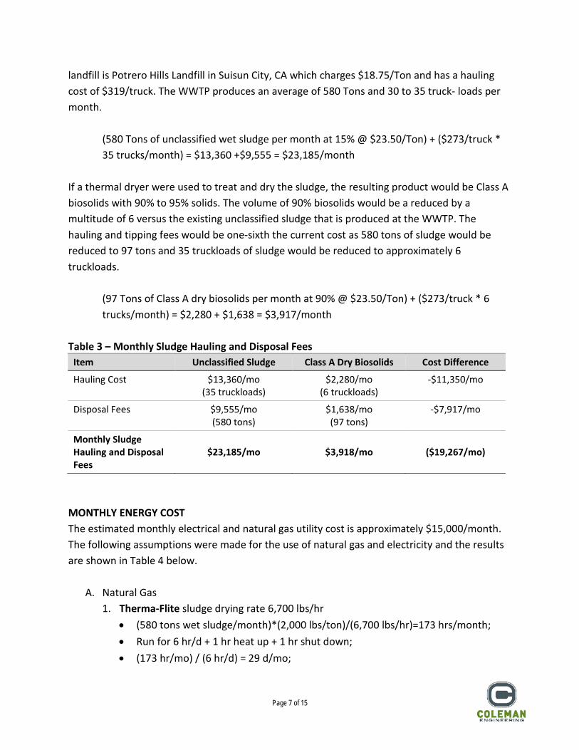
landfill is Potrero Hills Landfill in Suisun City, CA which charges $18.75/Ton and has a hauling cost of $319/truck. The WWTP produces an average of 580 Tons and 30 to 35 truck- loads per month.
(580 Tons of unclassified wet sludge per month at 15% @ $23.50/Ton) + ($273/truck * 35 trucks/month) = $13,360 +$9,555 = $23,185/month
If a thermal dryer were used to treat and dry the sludge, the resulting product would be Class A biosolids with 90% to 95% solids. The volume of 90% biosolids would be a reduced by a multitude of 6 versus the existing unclassified sludge that is produced at the WWTP. The hauling and tipping fees would be one-sixth the current cost as 580 tons of sludge would be reduced to 97 tons and 35 truckloads of sludge would be reduced to approximately 6 truckloads.
(97 Tons of Class A dry biosolids per month at 90% @ $23.50/Ton) + ($273/truck * 6 trucks/month) = $2,280 + $1,638 = $3,917/month
Table 3 – Monthly Sludge Hauling and Disposal Fees
Item Unclassified Sludge Class A Dry Biosolids Cost Difference
Hauling Cost $13,360/mo (35 truckloads)
$2,280/mo (6 truckloads)
-$11,350/mo
Disposal Fees $9,555/mo (580 tons)
$1,638/mo (97 tons)
-$7,917/mo
Monthly Sludge Hauling and Disposal Fees
$23,185/mo
$3,918/mo
($19,267/mo)
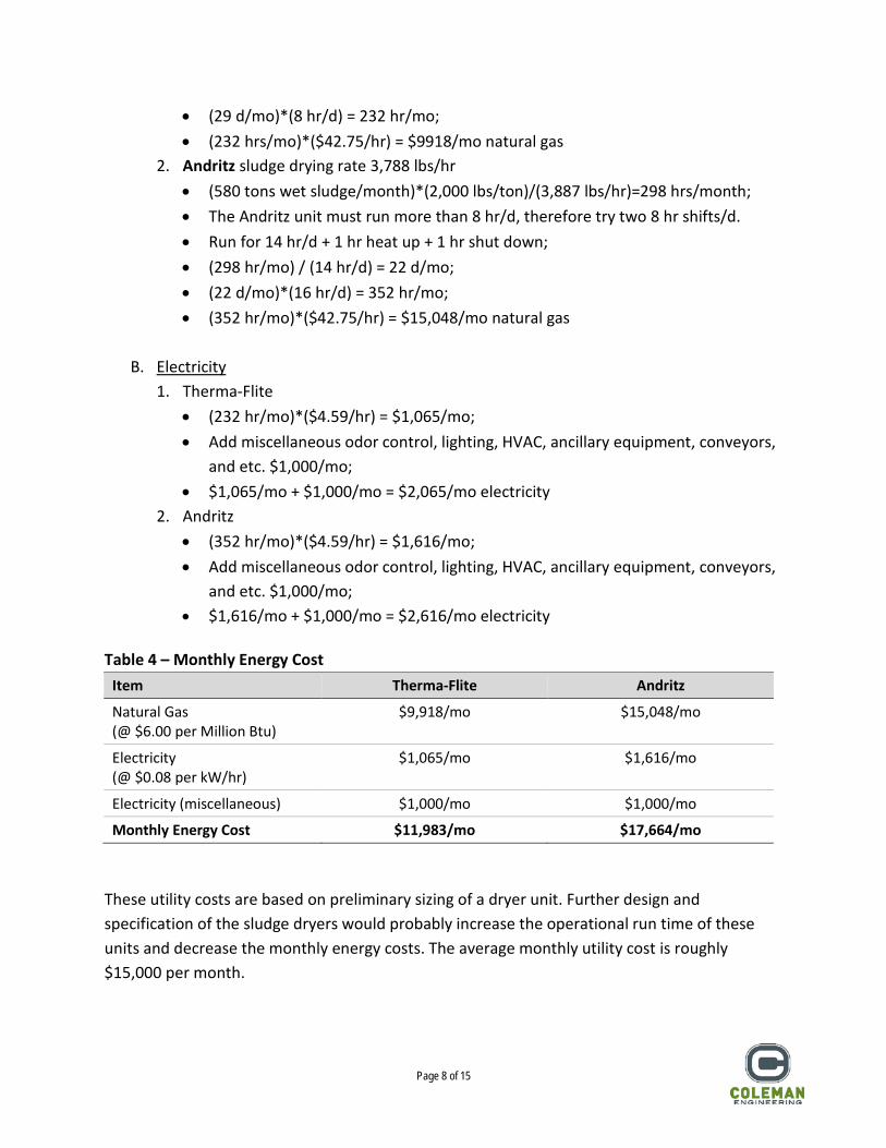
MONTHLY ENERGY COST The estimated monthly electrical and natural gas utility cost is approximately $15,000/month. The following assumptions were made for the use of natural gas and electricity and the results are shown in Table 4 below.
A. Natural Gas 1. Therma-Flite sludge drying rate 6,700 lbs/hr
• (580 tons wet sludge/month)*(2,000 lbs/ton)/(6,700 lbs/hr)=173 hrs/month; • Run for 6 hr/d + 1 hr heat up + 1 hr shut down; • (173 hr/mo) / (6 hr/d) = 29 d/mo;
Page 8 of 15
• (29 d/mo)*(8 hr/d) = 232 hr/mo; • (232 hrs/mo)*($42.75/hr) = $9918/mo natural gas
2. Andritz sludge drying rate 3,788 lbs/hr • (580 tons wet sludge/month)*(2,000 lbs/ton)/(3,887 lbs/hr)=298 hrs/month; • The Andritz unit must run more than 8 hr/d, therefore try two 8 hr shifts/d. • Run for 14 hr/d + 1 hr heat up + 1 hr shut down; • (298 hr/mo) / (14 hr/d) = 22 d/mo; • (22 d/mo)*(16 hr/d) = 352 hr/mo; • (352 hr/mo)*($42.75/hr) = $15,048/mo natural gas
B. Electricity
1. Therma-Flite • (232 hr/mo)*($4.59/hr) = $1,065/mo; • Add miscellaneous odor control, lighting, HVAC, ancillary equipment, conveyors,
and etc. $1,000/mo; • $1,065/mo + $1,000/mo = $2,065/mo electricity
2. Andritz • (352 hr/mo)*($4.59/hr) = $1,616/mo; • Add miscellaneous odor control, lighting, HVAC, ancillary equipment, conveyors,
and etc. $1,000/mo; • $1,616/mo + $1,000/mo = $2,616/mo electricity
Table 4 – Monthly Energy Cost
Item Therma-Flite Andritz
Natural Gas (@ $6.00 per Million Btu)
$9,918/mo $15,048/mo
Electricity (@ $0.08 per kW/hr)
$1,065/mo $1,616/mo
Electricity (miscellaneous) $1,000/mo $1,000/mo
Monthly Energy Cost $11,983/mo $17,664/mo These utility costs are based on preliminary sizing of a dryer unit. Further design and specification of the sludge dryers would probably increase the operational run time of these units and decrease the monthly energy costs. The average monthly utility cost is roughly $15,000 per month.
Page 9 of 15
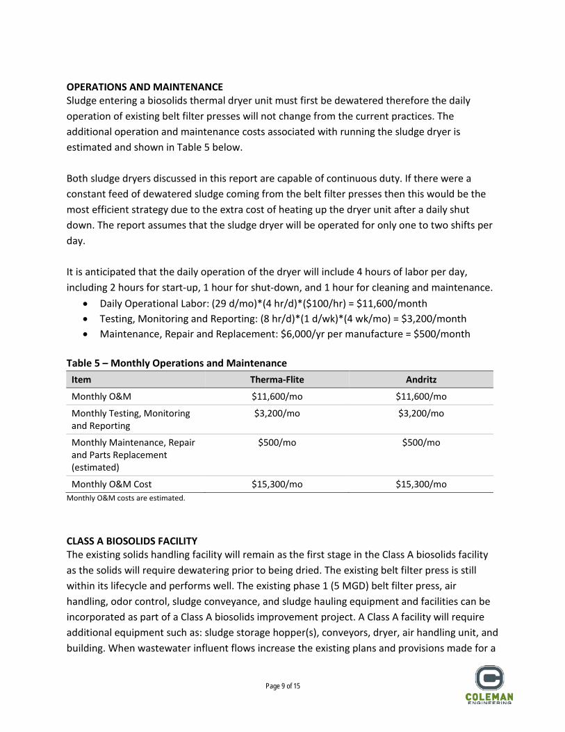
OPERATIONS AND MAINTENANCE Sludge entering a biosolids thermal dryer unit must first be dewatered therefore the daily operation of existing belt filter presses will not change from the current practices. The additional operation and maintenance costs associated with running the sludge dryer is estimated and shown in Table 5 below. Both sludge dryers discussed in this report are capable of continuous duty. If there were a constant feed of dewatered sludge coming from the belt filter presses then this would be the most efficient strategy due to the extra cost of heating up the dryer unit after a daily shut down. The report assumes that the sludge dryer will be operated for only one to two shifts per day. It is anticipated that the daily operation of the dryer will include 4 hours of labor per day, including 2 hours for start-up, 1 hour for shut-down, and 1 hour for cleaning and maintenance.
• Daily Operational Labor: (29 d/mo)*(4 hr/d)*($100/hr) = $11,600/month • Testing, Monitoring and Reporting: (8 hr/d)*(1 d/wk)*(4 wk/mo) = $3,200/month • Maintenance, Repair and Replacement: $6,000/yr per manufacture = $500/month
Table 5 – Monthly Operations and Maintenance
Item Therma-Flite Andritz
Monthly O&M $11,600/mo $11,600/mo
Monthly Testing, Monitoring and Reporting
$3,200/mo $3,200/mo
Monthly Maintenance, Repair and Parts Replacement (estimated)
$500/mo $500/mo
Monthly O&M Cost $15,300/mo $15,300/mo Monthly O&M costs are estimated. CLASS A BIOSOLIDS FACILITY The existing solids handling facility will remain as the first stage in the Class A biosolids facility as the solids will require dewatering prior to being dried. The existing belt filter press is still within its lifecycle and performs well. The existing phase 1 (5 MGD) belt filter press, air handling, odor control, sludge conveyance, and sludge hauling equipment and facilities can be incorporated as part of a Class A biosolids improvement project. A Class A facility will require additional equipment such as: sludge storage hopper(s), conveyors, dryer, air handling unit, and building. When wastewater influent flows increase the existing plans and provisions made for a
Page 10 of 15
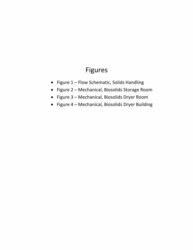
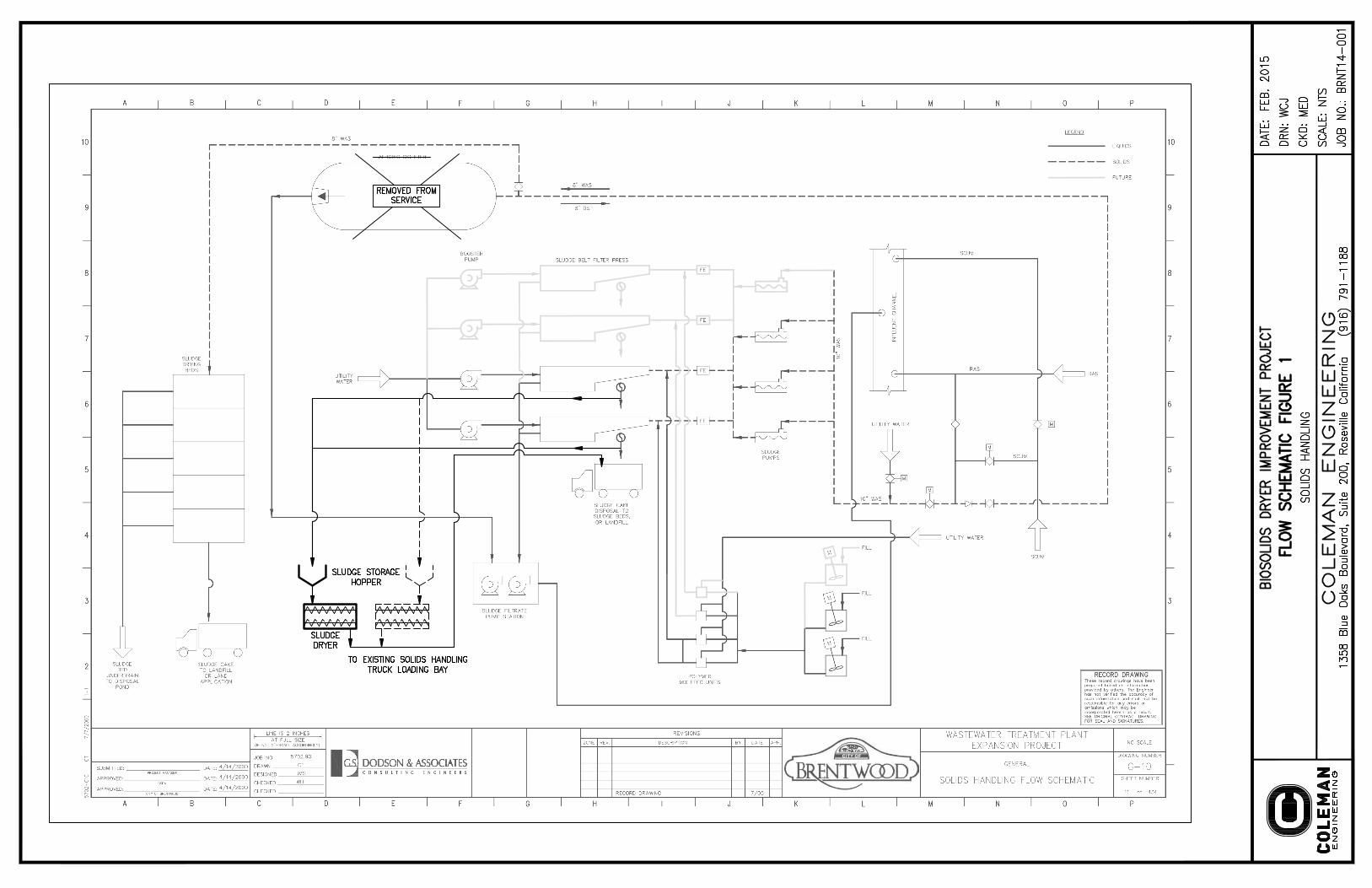
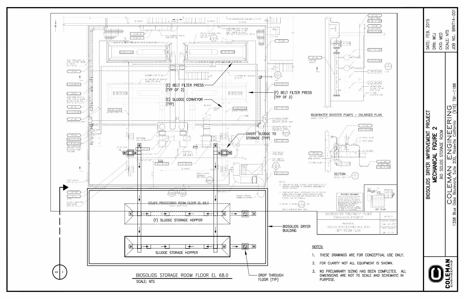
phase 2 (10 MGD) expansion of the belt filter presses would still be valid and apply to an expansion of the Class A biosolids facility. CONSTRUCTION The following facilities, equipment and tasks would be required. The sludge dryer has been added to the existing solids handling flow diagram in Figure 1. Figures 2, 3 and 4 show the conceptual mechanical improvements. The equipment shown in these figures shows only a conceptual layout of how Class A dryer improvements may be implemented into the existing solids handling systems. The facilities shown have not been sized, and are not shown to scale. Building – The existing building houses the phase 1 sludge feed pumps, belt filter presses, conveyors, air handling units, and truck loading bays. There is ample space for the phase 2 expansion but there is not enough additional space for the dryer and ancillary equipment. A new biosolids dryer building may be constructed adjacent to the solids handling building on the other side of the truck loading bays. Sludge Storage Hopper – Sludge that is continuously dewatered from the belt filter press with a 15% solids concentration will need to be stored for a period of 1 to 2 days prior to a batch dryer cycle. New sludge conveyors could move dewatered sludge from the belt filter presses across the existing solids handling building and truck loading bays to the sludge storage hopper. The hopper would be on the second level of the building with the dryer underneath it on the first level of the building. Sludge Dryer – The sludge dyer should be installed indoors to protect it from the elements and to provide a level of odor and dust control. The dryer should be located on the first floor of the new dryer building for ease of maintenance and to provide gravity feed from the sludge hopper on the second level above the dryer. Dried biosolids can be moved via conveyor from the dryer into the truck loading bays. Conveyors – Conveyors would be required to move dewatered sludge from the belt filter presses to the sludge storage hoppers, from the sludge storage hopper to the dryer unit, and then from the dryer unit to the truck loading bays. Odor and Dust Control – Air from the belt filter presses is captured by fume hoods overhanging the existing belt filter presses then pushed through a soil filter adjacent to the solids handling building. There is no evident odor emanating from the belt filter presses now so it is probable that odor will not be an issue for the dry biosolids, but the construction of an odor control unit should be considered in the case that the WWTP process changes and the solids start to give off
Page 11 of 15
foul smelling air. There is space in the foul air header for the phase 2 belt filter presses but not for additional foul air for a dryer and condenser/cooler. A foul air handling unit and odor removal system such as the existing soil filter should be considered in the preliminary design. Dust control may be required for the dry solids around the condenser/cooler and truck bays. Instrumentation, Control, and SCADA – To make it simpler for the operations and maintenance group all electrical, instrumentation, and control equipment should be compatible or match the current standard equipment at the WWTP, including PLCs, VFDs, protocol language, SCADA hardware and software, electrical switch gear, flow meters, gauges, flow control valves, and etc. All new control panels should be tied into the existing plant wide SCADA monitoring and control system including new supplemental programing and screens for the plant control center. The SCADA hardware, software, protocol, point address, should match or be compatible with the existing SCADA system and historian. Permitting – It is anticipated that a new solids handling building will require a building permit through the local City or County building department. Biosolids sampling according to 40 CFR 503 may be required to verify that the dry biosolids meet Class A requirements. The California Air Resources Board should be notified and any required permit submitted for the use of natural gas for the burner on the thermal heating unit or for dust generated during handling of the dry Class A biosolids. DESIGN The following tasks would be required to produce a full set of design and construction documents. Preliminary Design Report – A preliminary design report would be generated to further investigate the feasibility of alternative dryer units, select a preferred unit, and produce design parameters and preliminary design layout and budgetary cost estimate for the project. Geotechnical – A geotechnical investigation is required for the purpose of designing a solids handling building foundation plan. Survey – A topographic and utility survey in the area of the proposed improvements is essential for the design development and construction of this project. Environmental – It is assumed that the City of Brentwood WWTP has an existing CEQA document and SWPPP. This project would not be outside of the existing footprint or predefined

Page 12 of 15
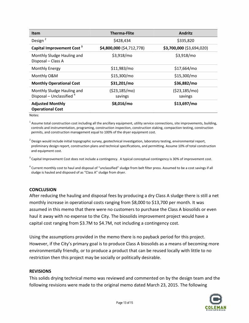
use and therefore it is not anticipated that any new environmental studies would be required. It is possible that Addendums or supplements to the existing documents may be required. Design – A full set of plans and technical specifications will need to be produced for the construction of this project including civil, structural, mechanical, electrical and possibly architectural disciplines. SUMMARY OF COSTS Construction Cost – For a budgetary cost estimate the construction cost is assumed to be 100% of the dryer equipment cost. This markup is intended to include all the ancillary equipment not provided in the equipment scope of supply, any utility service connections, site improvements, building, wet and dry utilities, controls and instrumentation, programing, construction inspection, construction staking, construction permits, compaction testing, and construction management. Design Fees – The design fees are assumed to be 10% of total construction and equipment cost. Design fees would include the topographic survey, geotechnical investigation, laboratory testing, environmental report, preliminary design report, construction plans and technical specifications, and regulatory permitting. The summary of the budgetary capital improvement costs and the monthly operation and maintenance costs are shown in Table 6 below. Note that a construction contingency cost is not included in Table 6 due to the lack of meaningful details at this point and due to the relatively large markup on equipment cost. A typical conceptual level contingency is 30% of the total construction, equipment, and design costs and should be applied during the pre-design stage. The capital improvement cost for the Therma-Flite unit is higher than the Andritz unit because there are more items included in the equipment scope of supply. It would therefore not be correct to conclude that the Andritz unit is a preferred over the Therma-Flite because the cost is lower. During the preliminary design phase more work would be done to size the units and adjust the scope of supply and specify ancillary equipment. The difference between the two dryer units should be considered a range of capital improvement costs. Table 6 – Budgetary Costs
Item Therma-Flite Andritz
Sludge Dryer Equipment, 1 unit
$2,142,172 $1,679,100
Construction 1 $2,142,172 $1,679,100
Page 13 of 15
Item Therma-Flite Andritz
Design 2 $428,434 $335,820
Capital Improvement Cost 3 $4,800,000 ($4,712,778) $3,700,000 ($3,694,020)
Monthly Sludge Hauling and Disposal – Class A
$3,918/mo $3,918/mo
Monthly Energy $11,983/mo $17,664/mo
Monthly O&M $15,300/mo $15,300/mo
Monthly Operational Cost $31,201/mo $36,882/mo
Monthly Sludge Hauling and Disposal – Unclassified 4
($23,185/mo) savings
($23,185/mo) savings
Adjusted Monthly Operational Cost
$8,016/mo $13,697/mo
Notes:
1 Assume total construction cost including all the ancillary equipment, utility service connections, site improvements, building, controls and instrumentation, programing, construction inspection, construction staking, compaction testing, construction permits, and construction management equal to 100% of the dryer equipment cost.
2 Design would include initial topographic survey, geotechnical investigation, laboratory testing, environmental report,
preliminary design report, construction plans and technical specifications, and permitting. Assume 10% of total construction and equipment cost.
3 Capital Improvement Cost does not include a contingency. A typical conceptual contingency is 30% of improvement cost. 4 Current monthly cost to haul and disposal of “unclassified” sludge from belt filter press. Assumed to be a cost savings if all
sludge is hauled and disposed of as “Class A” sludge from dryer. CONCLUSION After reducing the hauling and disposal fees by producing a dry Class A sludge there is still a net monthly increase in operational costs ranging from $8,000 to $13,700 per month. It was assumed in this memo that there were no customers to purchase the Class A biosolids or even haul it away with no expense to the City. The biosolids improvement project would have a capital cost ranging from $3.7M to $4.7M, not including a contingency cost. Using the assumptions provided in the memo there is no payback period for this project. However, if the City’s primary goal is to produce Class A biosolids as a means of becoming more environmentally friendly, or to produce a product that can be reused locally with little to no restriction then this project may be socially or politically desirable. REVISIONS This solids drying technical memo was reviewed and commented on by the design team and the following revisions were made to the original memo dated March 23, 2015. The following
Page 14 of 15
parameters were changed. These changes were then incorporated into the calculations resulting in a revised set of tabulated values. Revised Tables 3 through 6 are attached to this memo.
1. Electrical Costs changed from $0.08/kWh to $0.14/kWh. 2. Therma-Flite wet solids input feed rate changed from 6,700 lbs/hr to 6,400 lbs/hr. 3. Therma-Flite wet solids input sludge concentration changed from 18% to 15%. 4. Fuel costs for the dryer will not include dryer cool down time. 5. Dryer will be shown to operate continuously 24 hours per day and process one (1)
weeks storage of dewatered 15% sludge from the presses. This approach will assume one run cycle of the dryer per week.
6. It will be assumed that there will be no increase in operations staffing hours, and that all work including daily start up, shut down, cleaning, and maintenance of the dryer units, sludge feed pumps, and conveyors will be absorbed into the work details of the existing solids handling crew.
7. It is assumed that there will be no increase in operations or laboratory staffing hours, and that all work including regular testing, monitoring, and reporting of sludge will be absorbed into the already regular solids handling testing, monitoring, and reporting procedures.
8. Design fees shall be a percentage of the construction cost and not the major equipment cost.
REVISED CONCLUSIONS After the clarification that no new operations or technicians will be added to the staff the O&M, testing, monitoring, and reporting fees are reduced to $0.00 per month in Table 5. Construction costs were revised and itemized to a limited extent, but are still estimated and only budgetary. The design fees are calculated to be 15% of the construction cost and include engineering, field investigations, testing, permitting, and environmental. The budgetary cost estimate includes a 30% contingency. Refer to the revised Table 6 for budgetary costs. Using the revised parameters, the payback period is 89 years. If the sludge hauling and disposal costs were decreased, the payback period significantly can be significantly reduced. For example, if half of the Class A sludge were to be reused and hauled only a short distance so that the cost for hauling was $100/truck and disposed fee was at no charge the payback period would be 50 years.
Page 15 of 15
This technical memo outlines the foreseeable issues with constructing Class A sludge drying facility and does show that a payback of the facilities is probable. It is recommended that in the next phase a more in depth and detailed analysis and cost estimated of the project be developed. Also, the next phase of analysis should include some study and assessment of likely Class A disposal markets, including likely hauling distances, total annual application rates, cost to dispose, etc. Finally, the next phase of analysis should include some assessment of the need for the City to achieve Class A biosolids regardless of the cost. This analysis was limited to assessing payback periods and likely costs without regard to the absolute need for the facility and likely opportunity costs for not constructing a Class A biosolids facility. FIGURES
• Figure 1 – Flow Schematic, Solids Handling • Figure 2 – Mechanical, Biosolids Storage Room • Figure 3 – Mechanical, Biosolids Dryer Room • Figure 4 – Mechanical, Biosolids Dryer Building
APPENDICES
• Appendix A – Therma-Flite Proposal Q21676, August 20, 2014 • Appendix B – ANDRITZ Budgetary Information #1305144, May 31, 2013 • Appendix C – Revised Tables 3 through 6
REFERENCES
• 40 CFR Part 503 – Standards for the Use or Disposal of Sewage Sludge • A Plain English Guide to the EPA Part 503 Biosolids Rule, EPA/832/R-93/003, September
1994
Figures • Figure 1 – Flow Schematic, Solids Handling • Figure 2 – Mechanical, Biosolids Storage Room • Figure 3 – Mechanical, Biosolids Dryer Room • Figure 4 – Mechanical, Biosolids Dryer Building

Appendix A Therma-Flite Proposal Q21676, August 20, 2014

IC 5400Bio‐Scru Dryer System Prepared for: BRENTWOOD, CA ‐ CITY OF Project: Wastewater Treatment Plant Dryer Project Prepared by: Michael Stone Municipal Sales Manager August 20, 2012
Proposal
Q21676
R0
TF: 877‐Bio‐SLDS Ph: 707‐747‐5949 Fax: 707‐747‐5951
info@Therma‐Flite.com www.Therma‐Flite.com Corporate Headquarters
P.O. Box 847 849 Jackson St.
Benicia, CA 94510
2 Q21676 R0
Prepared by: Michael Stone For: Casey Wichert Date:08/20/12
Total Pages 18 Therma‐Flite 877‐DRY‐SLDS mstone@therma‐flite.com
IC BIO‐SCRU® 1 OVERVIEW
1.1 Description:
Therma‐Flite, IC 5400 is an automated, indirectly heated, continuous flow biosolids dryer system
with an ASME code‐stamped thermal fluid heating module and ASME code‐stamped dryer
module. The IC series dryers are complete turnkey biosolids dryer systems, modularly designed
for ease of installation. Programmable logic controller (PLC) automation and control of the IC
series system insures meeting 40 CFR, 503, Class A requirements while processing on a
continuous basis with minimal operator attention.
1.2 Scope:
The scope of this proposal includes the design and furnishing of a complete sludge dryer system.
The sludge dryer system shall consist of 1 unit, each consisting of the following components:
1.2.1 Feed hopper with integrated live feed bottom
1.2.2 PC pump feed system
1.2.3 BIO ‐SCRU® Dryer with integrated HOLO ‐SCRU® rotors
1.2.4 Thermal fluid heater fired with Natural Gas
1.2.5 Cooling screw and rotary discharge valve
1.2.6 Scrubber / condenser
1.2.7 NEMA 12 Control panel with Motor Starters and VFD’s
1.3 How the IC‐5400 BIO‐SCRU, Biosolids Dryer System Works:
The BIO‐SCRU’s® drying chamber is a sealed, null pressure, anaerobic atmosphere. The drying
chamber is kept constantly full to minimize head space in the chamber and to maximize the
thermal operating efficiency. The BIO‐SCRU’s® heat energy is provided by the thermal fluid
circulating through the hollow rotor flighting, rotor shaft and dryer chamber housing. This
method of heating is indirect, meaning the heating medium is not in contact with the product
being heated.
The BIO‐SCRU’s® independently driven, variable speed, dual‐rotor design includes proprietary
features which make the rotors self‐clearing. This feature breaks up any sludge that may bake
onto the rotors and/or form clumps. This also promotes mixing of the sludge.
3 Q21676 R0
Prepared by: Michael Stone For: Casey Wichert Date:08/20/12
Total Pages 18 Therma‐Flite 877‐DRY‐SLDS mstone@therma‐flite.com
The BIO‐SCRU® dryer design can also incorporate mixing blades, which break up any large
clumps and homogenize the particle size to insure the sludge is uniformly heated throughout
the unit.
The BIO‐SCRU® dryer utilizes a multi‐sensing‐point method for failsafe operation. The PLC‐
controlled scrubber/condenser insures that small particulate is captured within the condensate
stream to minimize odors.
2 PERFORMANCE AND CAPACITY
2.1 IC 5400 Operation Parameters:
2.1.1 Method: Automated, indirectly heated, continuous flow dehydration system.
2.1.2 Capacity: 4900 to 5400 pounds of water removal per hour.
2.1.3 Hopper: 28 cubic yards standard, other options are available.
2.1.4 Process feeds can include digested, undigested, waste activated bio sludge or a mixture of multiple types of sludge as is common in regional facilities.
2.1.5 Designed for variable processing rates up to continuous 24/7 operation.
2.1.6 Primary or mixtures of sludges high in fats, oil, and grease will de‐rate the capacity of the equipment.
2.2 Energy Utilization:
2.2.1 Dryer chamber efficiency: 95%
2.2.2 Thermal fluid heater efficiency:
2.2.2.1 86.5% (LHV) with natural gas based off Fulton’s requirements.
2.2.2.2 Optional high efficiency natural gas heater 91% (LHV)
2.2.3 Thermal fluid heater max heat output: 8 MMBtu
2.2.4 Natural Gas consumption: Nominal 1450 Btu/pound of water removed. Primary sludge or sludge heavy in fats, oils, and greases will increase the percent energy required for drying.
4 Q21676 R0
Prepared by: Michael Stone For: Casey Wichert Date:08/20/12
Total Pages 18 Therma‐Flite 877‐DRY‐SLDS mstone@therma‐flite.com
2.3 Electrical Motors:
2.3.1 Dryer rotors drive 15 hp
2.3.2 Hopper drive 10 hp
2.3.3 Hopper feed pump 20 hp
2.3.4 Combustion fan 15 hp
2.3.5 Thermal fluid pump 40 hp
2.3.6 Condenser fan motor 1 hp
2.3.7 Rotary valve 1 hp
2.3.8 Cooling screw conveyor 5 hp
107 total hp
Note: Horsepower ratings are estimated for the standard BIO‐SCRU® System. Final layout and
auxiliary equipment may change the total connected horsepower.
2.4 Utilities:
2.4.1 Natural gas pressure required: 40” wc
2.4.2 Fuel Supply Line Requirements: Natural gas (@1000BTU/CU.FT.) 9997 cu.ft/hr
2.4.3 Condenser water required: (cooling water is included) requires 235 gpm at 45 psi, not to exceed 60 psi of water flow. If non‐potable water is used, it must be filtered through a 30 mesh filtration before delivery to the condenser/scrubber. Filtration and shut off valve supplied by Owner.
2.4.4 Main electrical disconnect: 175 amp
2.5 Miscellaneous:
2.5.1 The flue gasses are to be exhausted in an 24" diameter duct provided by Owner
3 COMPLIANCE WITH 40 CFR 503 RULES TO PRODUCE CLASS A BIOSOLIDS
3.1 The Therma‐Flite Sludge Dryer is a unique continuous processor that can produce Class A biosolids reliably while complying with the 40 CFR 503 regulations. Compliance with both the pathogen reduction and vector attraction reduction requirements for Class A biosolids is met with different operating regimen and compliance logging options.
5 Q21676 R0
Prepared by: Michael Stone For: Casey Wichert Date:08/20/12
Total Pages 18 Therma‐Flite 877‐DRY‐SLDS mstone@therma‐flite.com
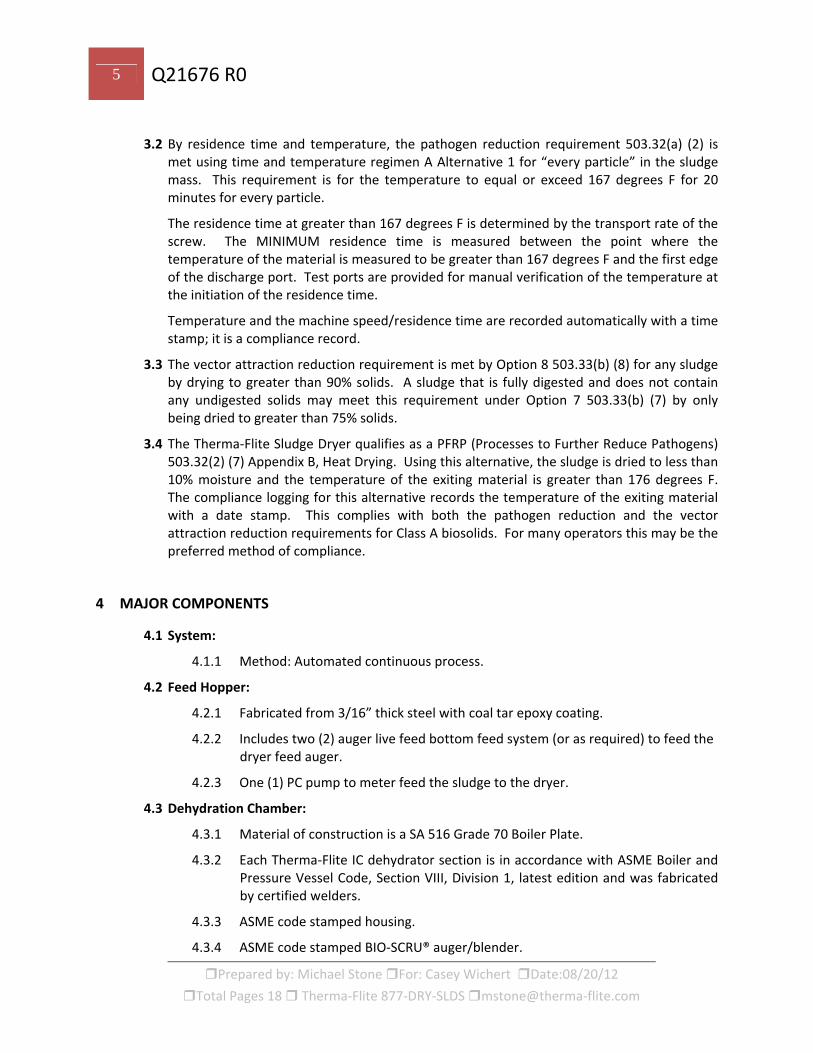
3.2 By residence time and temperature, the pathogen reduction requirement 503.32(a) (2) is met using time and temperature regimen A Alternative 1 for “every particle” in the sludge mass. This requirement is for the temperature to equal or exceed 167 degrees F for 20 minutes for every particle.
The residence time at greater than 167 degrees F is determined by the transport rate of the screw. The MINIMUM residence time is measured between the point where the temperature of the material is measured to be greater than 167 degrees F and the first edge of the discharge port. Test ports are provided for manual verification of the temperature at the initiation of the residence time.
Temperature and the machine speed/residence time are recorded automatically with a time stamp; it is a compliance record.
3.3 The vector attraction reduction requirement is met by Option 8 503.33(b) (8) for any sludge by drying to greater than 90% solids. A sludge that is fully digested and does not contain any undigested solids may meet this requirement under Option 7 503.33(b) (7) by only being dried to greater than 75% solids.
3.4 The Therma‐Flite Sludge Dryer qualifies as a PFRP (Processes to Further Reduce Pathogens) 503.32(2) (7) Appendix B, Heat Drying. Using this alternative, the sludge is dried to less than 10% moisture and the temperature of the exiting material is greater than 176 degrees F. The compliance logging for this alternative records the temperature of the exiting material with a date stamp. This complies with both the pathogen reduction and the vector attraction reduction requirements for Class A biosolids. For many operators this may be the preferred method of compliance.
4 MAJOR COMPONENTS
4.1 System:
4.1.1 Method: Automated continuous process.
4.2 Feed Hopper:
4.2.1 Fabricated from 3/16” thick steel with coal tar epoxy coating.
4.2.2 Includes two (2) auger live feed bottom feed system (or as required) to feed the dryer feed auger.
4.2.3 One (1) PC pump to meter feed the sludge to the dryer.
4.3 Dehydration Chamber:
4.3.1 Material of construction is a SA 516 Grade 70 Boiler Plate.
4.3.2 Each Therma‐Flite IC dehydrator section is in accordance with ASME Boiler and Pressure Vessel Code, Section VIII, Division 1, latest edition and was fabricated by certified welders.
4.3.3 ASME code stamped housing.
4.3.4 ASME code stamped BIO‐SCRU® auger/blender.
6 Q21676 R0
Prepared by: Michael Stone For: Casey Wichert Date:08/20/12
Total Pages 18 Therma‐Flite 877‐DRY‐SLDS mstone@therma‐flite.com
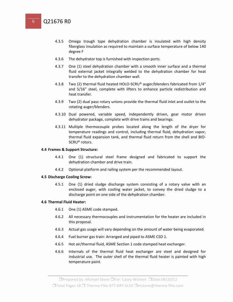
4.3.5 Omega trough type dehydration chamber is insulated with high density fiberglass insulation as required to maintain a surface temperature of below 140 degree F
4.3.6 The dehydrator top is furnished with inspection ports.
4.3.7 One (1) steel dehydration chamber with a smooth inner surface and a thermal fluid external jacket integrally welded to the dehydration chamber for heat transfer to the dehydration chamber wall.
4.3.8 Two (2) thermal fluid heated HOLO‐SCRU® auger/blenders fabricated from 1/4" and 5/16” steel, complete with lifters to enhance particle redistribution and heat transfer.
4.3.9 Two (2) dual pass rotary unions provide the thermal fluid inlet and outlet to the rotating auger/blenders.
4.3.10 Dual powered, variable speed, independently driven, gear motor driven dehydrator package, complete with drive trains and bearings.
4.3.11 Multiple thermocouple probes located along the length of the dryer for temperature readings and control, including thermal fluid, dehydration vapor, thermal fluid expansion tank, and thermal fluid return from the shell and BIO‐SCRU® rotors.
4.4 Frames & Support Structure:
4.4.1 One (1) structural steel frame designed and fabricated to support the dehydration chamber and drive train.
4.4.2 Optional platform and railing system per the recommended layout.
4.5 Discharge Cooling Screw:
4.5.1 One (1) dried sludge discharge system consisting of a rotary valve with an enclosed auger, with cooling water jacket, to convey the dried sludge to a discharge point on one side of the dehydration chamber.
4.6 Thermal Fluid Heater:
4.6.1 One (1) ASME code stamped.
4.6.2 All necessary thermocouples and instrumentation for the heater are included in this proposal.
4.6.3 Actual gas usage will vary depending on the amount of water being evaporated.
4.6.4 Fuel burner gas train: Arranged and piped to ASME CSD 1.
4.6.5 Hot air/thermal fluid, ASME Section 1 code stamped heat exchanger.
4.6.6 Internals of the thermal fluid heat exchanger are steel and designed for industrial use. The outer shell of the thermal fluid heater is painted with high temperature paint.
7 Q21676 R0
Prepared by: Michael Stone For: Casey Wichert Date:08/20/12
Total Pages 18 Therma‐Flite 877‐DRY‐SLDS mstone@therma‐flite.com
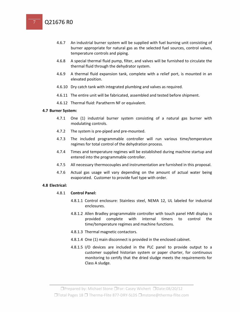
4.6.7 An industrial burner system will be supplied with fuel burning unit consisting of burner appropriate for natural gas as the selected fuel sources, control valves, temperature controls and piping.
4.6.8 A special thermal fluid pump, filter, and valves will be furnished to circulate the thermal fluid through the dehydrator system.
4.6.9 A thermal fluid expansion tank, complete with a relief port, is mounted in an elevated position.
4.6.10 Dry catch tank with integrated plumbing and valves as required.
4.6.11 The entire unit will be fabricated, assembled and tested before shipment.
4.6.12 Thermal fluid: Paratherm NF or equivalent.
4.7 Burner System:
4.7.1 One (1) industrial burner system consisting of a natural gas burner with modulating controls.
4.7.2 The system is pre‐piped and pre‐mounted.
4.7.3 The included programmable controller will run various time/temperature regimes for total control of the dehydration process.
4.7.4 Times and temperature regimes will be established during machine startup and entered into the programmable controller.
4.7.5 All necessary thermocouples and instrumentation are furnished in this proposal.
4.7.6 Actual gas usage will vary depending on the amount of actual water being evaporated. Customer to provide fuel type with order.
4.8 Electrical:
4.8.1 Control Panel:
4.8.1.1 Control enclosure: Stainless steel, NEMA 12, UL labeled for industrial enclosures.
4.8.1.2 Allen Bradley programmable controller with touch panel HMI display is provided complete with internal timers to control the time/temperature regimes and machine functions.
4.8.1.3 Thermal magnetic contactors.
4.8.1.4 One (1) main disconnect is provided in the enclosed cabinet.
4.8.1.5 I/O devices are included in the PLC panel to provide output to a customer supplied historian system or paper charter, for continuous monitoring to certify that the dried sludge meets the requirements for Class A sludge.

8 Q21676 R0
Prepared by: Michael Stone For: Casey Wichert Date:08/20/12
Total Pages 18 Therma‐Flite 877‐DRY‐SLDS mstone@therma‐flite.com
4.8.1.6 Outputs for additional recorders, for record keeping, or SCADA systems, can be furnished at an additional cost.
4.8.1.7 Motors are Totally Enclosed Fan Cooled classification.
4.8.2 Wiring:
4.8.2.1 Machine wiring: Wired to national electrical codes.
4.8.2.2 Conduit: All conduits will be rigid except where liquid tight is required and approved.
4.8.3 Supplied Operations and Maintenance Manuals:
4.8.3.1 Therma‐Flite will supply Operations and Maintenance manuals per specifications
4.8.3.2 All hard wiring schematics are furnished.
4.9 Condenser/Scrubber:
4.9.1 Brass valves
4.9.2 304 SS nozzles
4.9.3 Water shut‐off valves, pressure‐reducing valves or flow meters supplied by Owner.
4.9.4 A high efficiency enclosed wet Venturi type scrubber is provided to remove airborne particulate.
4.9.5 Condenser water will be piped back to the waste treatment system by the Owner.
5 OPERATIONAL SAFETY
5.1 Dryer Chamber: 5.1.1 The drying chamber includes purge gas connections to supply inerting gas
padding to the system during startup and shutdown or while steam production is below what is required for normal operation. Gas feed is controlled automatically via a solenoid valve.
5.1.2 Drying chamber will include water nozzles along the length of the dryer. In the event of an over‐temperature, a solenoid valve will actuate, initiating a saturation of the bio‐solids in the drying chamber. After completion of the saturation cycle, the dryer will initiate a slow heat up and bake out to insure the product in the chamber is thoroughly dried before discharge.
5.1.3 Nitrogen Purge is also incorporated into the dryer system as an added safety. If for any reason that the water system goes down, the nitrogen system backs up the standard water safety.
9 Q21676 R0
Prepared by: Michael Stone For: Casey Wichert Date:08/20/12
Total Pages 18 Therma‐Flite 877‐DRY‐SLDS mstone@therma‐flite.com
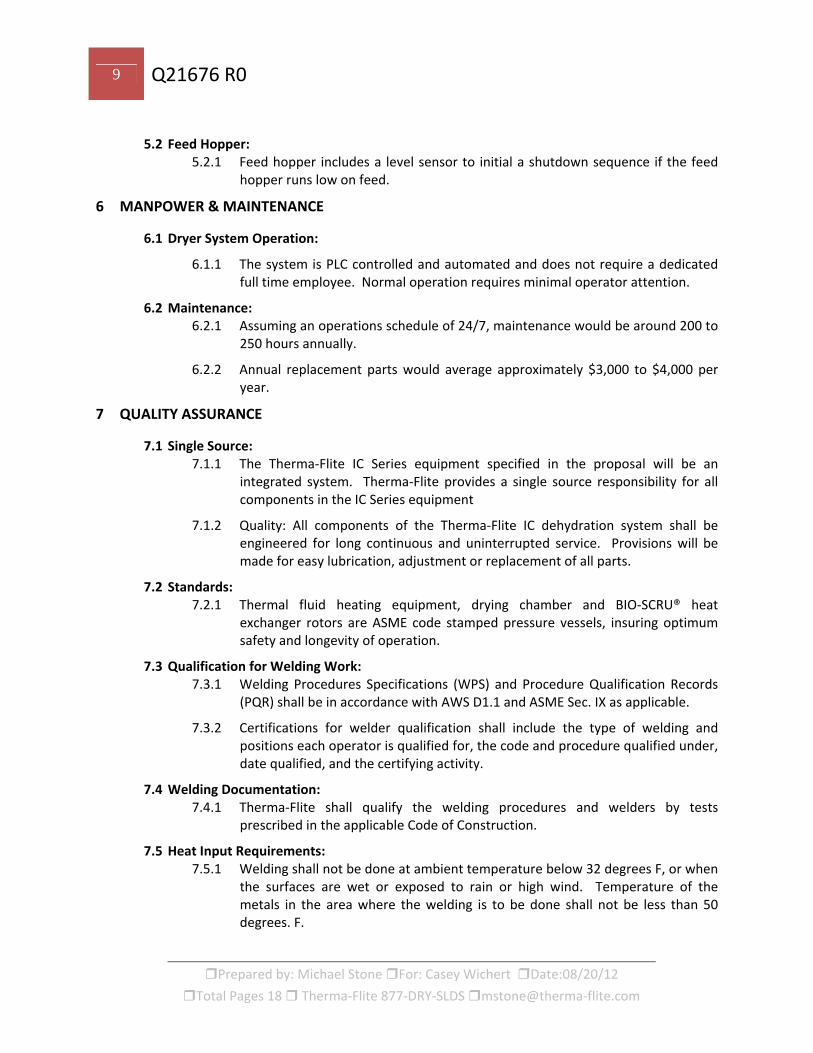
5.2 Feed Hopper: 5.2.1 Feed hopper includes a level sensor to initial a shutdown sequence if the feed
hopper runs low on feed.
6 MANPOWER & MAINTENANCE
6.1 Dryer System Operation:
6.1.1 The system is PLC controlled and automated and does not require a dedicated full time employee. Normal operation requires minimal operator attention.
6.2 Maintenance: 6.2.1 Assuming an operations schedule of 24/7, maintenance would be around 200 to
250 hours annually.
6.2.2 Annual replacement parts would average approximately $3,000 to $4,000 per year.
7 QUALITY ASSURANCE
7.1 Single Source: 7.1.1 The Therma‐Flite IC Series equipment specified in the proposal will be an
integrated system. Therma‐Flite provides a single source responsibility for all components in the IC Series equipment
7.1.2 Quality: All components of the Therma‐Flite IC dehydration system shall be engineered for long continuous and uninterrupted service. Provisions will be made for easy lubrication, adjustment or replacement of all parts.
7.2 Standards: 7.2.1 Thermal fluid heating equipment, drying chamber and BIO‐SCRU® heat
exchanger rotors are ASME code stamped pressure vessels, insuring optimum safety and longevity of operation.
7.3 Qualification for Welding Work: 7.3.1 Welding Procedures Specifications (WPS) and Procedure Qualification Records
(PQR) shall be in accordance with AWS D1.1 and ASME Sec. IX as applicable.
7.3.2 Certifications for welder qualification shall include the type of welding and positions each operator is qualified for, the code and procedure qualified under, date qualified, and the certifying activity.
7.4 Welding Documentation: 7.4.1 Therma‐Flite shall qualify the welding procedures and welders by tests
prescribed in the applicable Code of Construction.
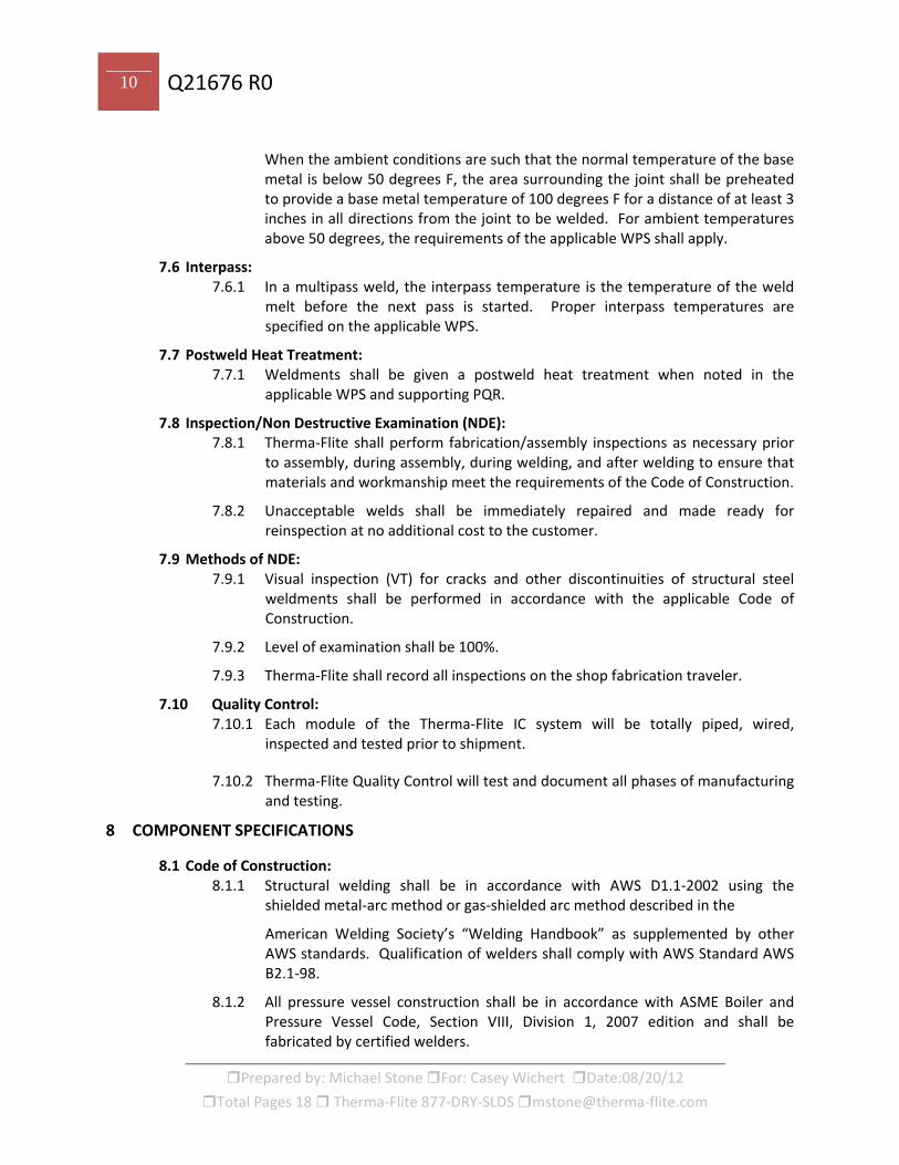
7.5 Heat Input Requirements: 7.5.1 Welding shall not be done at ambient temperature below 32 degrees F, or when
the surfaces are wet or exposed to rain or high wind. Temperature of the metals in the area where the welding is to be done shall not be less than 50 degrees. F.
10 Q21676 R0
Prepared by: Michael Stone For: Casey Wichert Date:08/20/12
Total Pages 18 Therma‐Flite 877‐DRY‐SLDS mstone@therma‐flite.com
When the ambient conditions are such that the normal temperature of the base metal is below 50 degrees F, the area surrounding the joint shall be preheated to provide a base metal temperature of 100 degrees F for a distance of at least 3 inches in all directions from the joint to be welded. For ambient temperatures above 50 degrees, the requirements of the applicable WPS shall apply.
7.6 Interpass: 7.6.1 In a multipass weld, the interpass temperature is the temperature of the weld
melt before the next pass is started. Proper interpass temperatures are specified on the applicable WPS.
7.7 Postweld Heat Treatment: 7.7.1 Weldments shall be given a postweld heat treatment when noted in the
applicable WPS and supporting PQR.
7.8 Inspection/Non Destructive Examination (NDE): 7.8.1 Therma‐Flite shall perform fabrication/assembly inspections as necessary prior
to assembly, during assembly, during welding, and after welding to ensure that materials and workmanship meet the requirements of the Code of Construction.
7.8.2 Unacceptable welds shall be immediately repaired and made ready for reinspection at no additional cost to the customer.
7.9 Methods of NDE: 7.9.1 Visual inspection (VT) for cracks and other discontinuities of structural steel
weldments shall be performed in accordance with the applicable Code of Construction.
7.9.2 Level of examination shall be 100%.
7.9.3 Therma‐Flite shall record all inspections on the shop fabrication traveler.
7.10 Quality Control: 7.10.1 Each module of the Therma‐Flite IC system will be totally piped, wired,
inspected and tested prior to shipment.
7.10.2 Therma‐Flite Quality Control will test and document all phases of manufacturing and testing.
8 COMPONENT SPECIFICATIONS
8.1 Code of Construction: 8.1.1 Structural welding shall be in accordance with AWS D1.1‐2002 using the
shielded metal‐arc method or gas‐shielded arc method described in the
American Welding Society’s “Welding Handbook” as supplemented by other AWS standards. Qualification of welders shall comply with AWS Standard AWS B2.1‐98.
8.1.2 All pressure vessel construction shall be in accordance with ASME Boiler and Pressure Vessel Code, Section VIII, Division 1, 2007 edition and shall be fabricated by certified welders.

11 Q21676 R0
Prepared by: Michael Stone For: Casey Wichert Date:08/20/12
Total Pages 18 Therma‐Flite 877‐DRY‐SLDS mstone@therma‐flite.com
8.2 Coatings: 8.2.1 Steel fabrications will be sand blasted and coated with one (1) coat of zinc rich
primer and a minimum of 3 mill thickness of corrosion resistant coating.
8.2.2 Any defects or damage caused in manufacturing will be thoroughly cleaned, wire brushed, wiped clean with a suitable solvent and dried. The prepared area will be coated with a zinc rich compound specifically formulated for wet environments. The zinc rich coating will be a minimum of 3 mills thick and will be in accordance with SSPC standards.
8.3 Seals: 8.3.1 The thermal fluid pump is manufactured by Dean Pump or equal
8.3.2 Seal specifications are:
8.3.2.1 Max. pressure‐ 350 PSIG
8.3.2.2 Max. temperature‐ 650 degrees F
8.3.2.3 Air cooled seals
8.3.2.4 Stationary seal‐ silicon carbide, and Viton®
8.3.3 Rotary seal‐ stainless steel, carbon and Viton®
8.3.4 Thermal fluid rotary joint seals. Rotary joints are Johnson Products, or equivalent
8.3.4.1 Convex, self‐aligning carbon seal ring, for extended life
8.3.4.2 Internal SS spring
8.3.4.3 Two (2) Internal, extended, carbon guides
8.4 Bearings: 8.4.1 Bearings will be oil or grease lubricated, with lubrication points piped to a
central lubrication block for ease of lubrication.
8.4.2 Bearings shall be a minimum of L‐10 rated life of 50,000 hours.
8.5 Balance: 8.5.1 Drive motors are manufactured by Nord or equal.
8.5.1.1 Balancing specifications are:
8.5.1.1.1 To ISO 1940/73
8.5.1.1.2 ISO procedure states the following equation: U=(e X m) /R
8.5.1.1.3 Where e= maximum residual unbalance in function of speed, mass and balance.
8.5.1.1.4 Grade (G) (mm X g/kg)
8.5.1.1.5 m = mass of rigid rotating body (kg)
8.5.1.1.6 R = balancing radius (distance from the center of the shaft to the compensating position (mm)
12 Q21676 R0
Prepared by: Michael Stone For: Casey Wichert Date:08/20/12
Total Pages 18 Therma‐Flite 877‐DRY‐SLDS mstone@therma‐flite.com
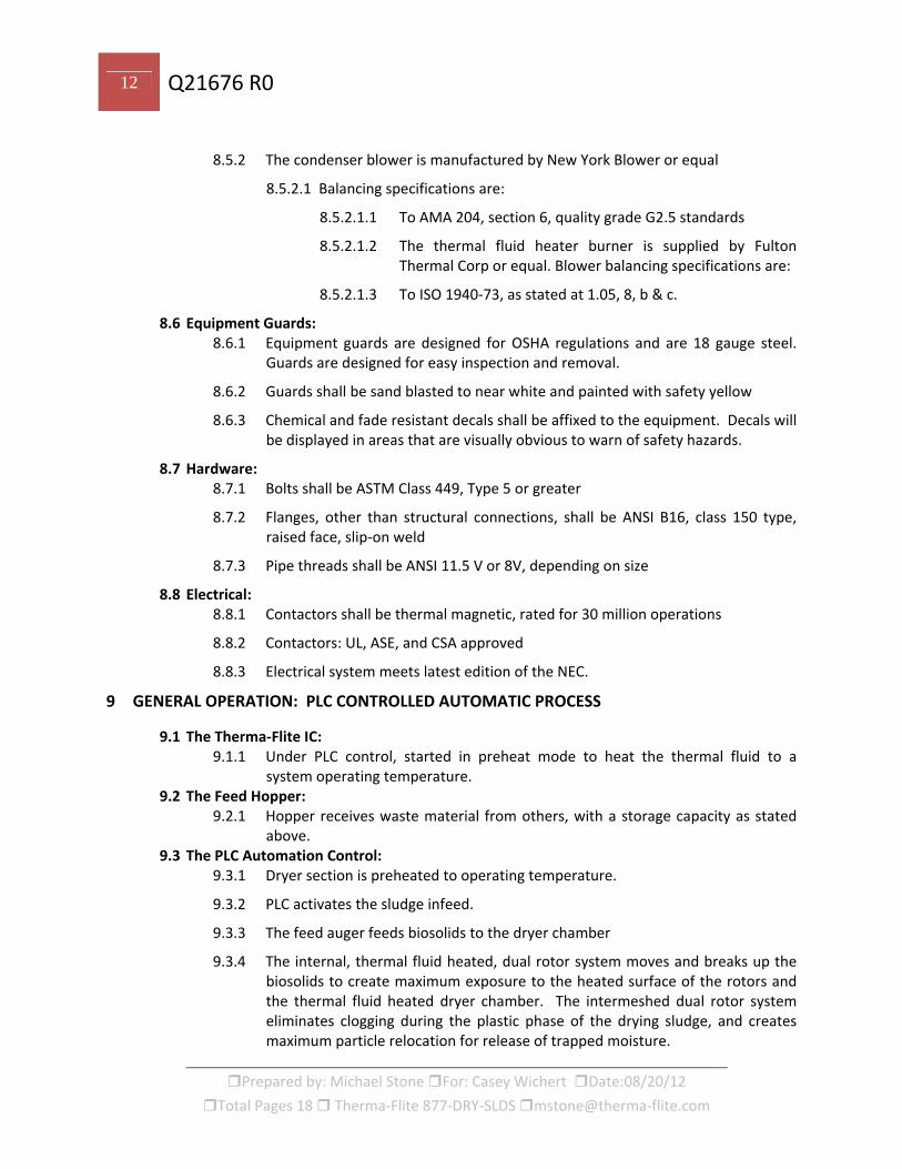
8.5.2 The condenser blower is manufactured by New York Blower or equal
8.5.2.1 Balancing specifications are:
8.5.2.1.1 To AMA 204, section 6, quality grade G2.5 standards
8.5.2.1.2 The thermal fluid heater burner is supplied by Fulton Thermal Corp or equal. Blower balancing specifications are:
8.5.2.1.3 To ISO 1940‐73, as stated at 1.05, 8, b & c.
8.6 Equipment Guards: 8.6.1 Equipment guards are designed for OSHA regulations and are 18 gauge steel.
Guards are designed for easy inspection and removal.
8.6.2 Guards shall be sand blasted to near white and painted with safety yellow
8.6.3 Chemical and fade resistant decals shall be affixed to the equipment. Decals will be displayed in areas that are visually obvious to warn of safety hazards.
8.7 Hardware: 8.7.1 Bolts shall be ASTM Class 449, Type 5 or greater
8.7.2 Flanges, other than structural connections, shall be ANSI B16, class 150 type, raised face, slip‐on weld
8.7.3 Pipe threads shall be ANSI 11.5 V or 8V, depending on size
8.8 Electrical: 8.8.1 Contactors shall be thermal magnetic, rated for 30 million operations
8.8.2 Contactors: UL, ASE, and CSA approved
8.8.3 Electrical system meets latest edition of the NEC.
9 GENERAL OPERATION: PLC CONTROLLED AUTOMATIC PROCESS
9.1 The Therma‐Flite IC: 9.1.1 Under PLC control, started in preheat mode to heat the thermal fluid to a
system operating temperature. 9.2 The Feed Hopper:
9.2.1 Hopper receives waste material from others, with a storage capacity as stated above.
9.3 The PLC Automation Control: 9.3.1 Dryer section is preheated to operating temperature.
9.3.2 PLC activates the sludge infeed.
9.3.3 The feed auger feeds biosolids to the dryer chamber
9.3.4 The internal, thermal fluid heated, dual rotor system moves and breaks up the biosolids to create maximum exposure to the heated surface of the rotors and the thermal fluid heated dryer chamber. The intermeshed dual rotor system eliminates clogging during the plastic phase of the drying sludge, and creates maximum particle relocation for release of trapped moisture.
13 Q21676 R0
Prepared by: Michael Stone For: Casey Wichert Date:08/20/12
Total Pages 18 Therma‐Flite 877‐DRY‐SLDS mstone@therma‐flite.com
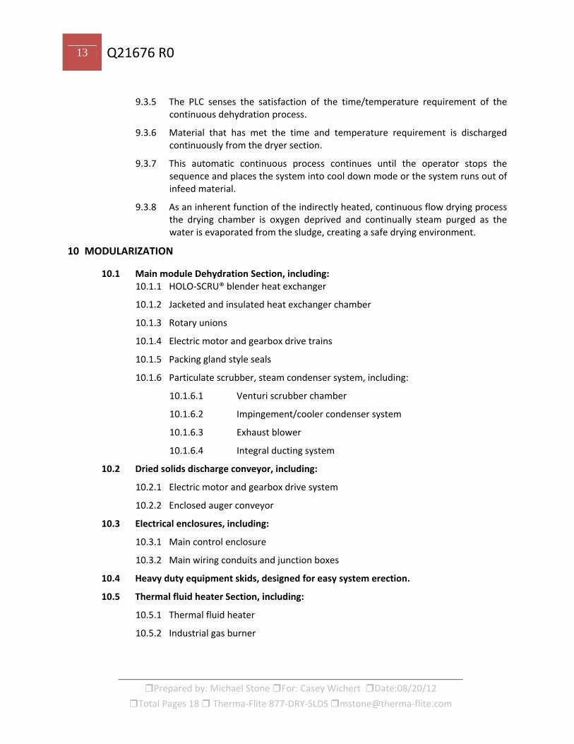
9.3.5 The PLC senses the satisfaction of the time/temperature requirement of the continuous dehydration process.
9.3.6 Material that has met the time and temperature requirement is discharged continuously from the dryer section.
9.3.7 This automatic continuous process continues until the operator stops the sequence and places the system into cool down mode or the system runs out of infeed material.
9.3.8 As an inherent function of the indirectly heated, continuous flow drying process the drying chamber is oxygen deprived and continually steam purged as the water is evaporated from the sludge, creating a safe drying environment.
10 MODULARIZATION
10.1 Main module Dehydration Section, including: 10.1.1 HOLO‐SCRU® blender heat exchanger
10.1.2 Jacketed and insulated heat exchanger chamber
10.1.3 Rotary unions
10.1.4 Electric motor and gearbox drive trains
10.1.5 Packing gland style seals
10.1.6 Particulate scrubber, steam condenser system, including:
10.1.6.1 Venturi scrubber chamber
10.1.6.2 Impingement/cooler condenser system
10.1.6.3 Exhaust blower
10.1.6.4 Integral ducting system
10.2 Dried solids discharge conveyor, including:
10.2.1 Electric motor and gearbox drive system
10.2.2 Enclosed auger conveyor
10.3 Electrical enclosures, including:
10.3.1 Main control enclosure
10.3.2 Main wiring conduits and junction boxes
10.4 Heavy duty equipment skids, designed for easy system erection.
10.5 Thermal fluid heater Section, including:
10.5.1 Thermal fluid heater
10.5.2 Industrial gas burner

14 Q21676 R0
Prepared by: Michael Stone For: Casey Wichert Date:08/20/12
Total Pages 18 Therma‐Flite 877‐DRY‐SLDS mstone@therma‐flite.com
10.5.3 Prepiped gas control system.
10.5.4 Thermal fluid expansion tank
10.5.5 Integral piping and valves
10.5.6 Dry catch tank with valves
10.5.7 Thermal fluid pump
10.5.8 Heavy duty equipment skid, designed for easy system erection
10.6 Hopper infeed, including:
10.6.1 Heavy duty hopper storage/infeed system
10.6.2 Infeed PC pump and feed pipe
10.6.3 Hopper drive system
10.6.4 Heavy duty equipment skid, designed for easy system erection
11 MANUALS, DRAWINGS AND SUBMITTAL PACKAGES
11.1 Manuals: 11.1.1 Two (2) Owner’s manuals will be provided, complete with as‐built drawings.
(Additional manuals and drawings will be provided on CD.)
11.2 Submittals: 11.2.1 Two (2) submittal packages will be provided, complete with submittal drawings.
12 PERFORMANCE AND ACCEPTANCE
12.1 Performance Test: 12.1.1 The performance test shall consist of a minimum of three (3) tests and shall be
performed over a minimum of eight (8) hours. All tests shall be averaged to demonstrate compliance with specified performance criteria.
12.1.2 The performance tests will be conducted in accordance with the requirements of 40 CFR Part 503.
12.1.3 The Owner will give acceptance after three consecutive tests meet the performance as required. The Owner will have a test laboratory available for analysis with no more than a twenty‐four (24) hour turnaround on the test samples.
12.1.4 Sampling and testing costs shall be the responsibility of the Owner.
12.1.5 The Owner does have the option of accepting the system per the time/temperature regime and the percent solids.
12.1.6 The performance testing must be arranged and completed during the five (5) day start‐up period. If, through no fault of Therma‐Flite, Therma‐Flite is not able to run the performance test within 30 days, performance test payment is due.

15 Q21676 R0
Prepared by: Michael Stone For: Casey Wichert Date:08/20/12
Total Pages 18 Therma‐Flite 877‐DRY‐SLDS mstone@therma‐flite.com
13 STARTUP ASSISTANCE / INSTALLATION SUPPORT
13.1 Startup Support: 13.1.1 Therma‐Flite will provide a trained technician for up to ten (10) days to startup
and program the system and train the operators.
13.1.2 Extra days are available at $1500.00 (when included in the same trip) per man‐day, plus expenses.
13.2 Installation Support: 13.2.1 Therma‐Flite will provide a trained technician for three (3) days to review
and/or supervise the installation of utility connections.
13.2.2 Extra days are available at $1500.00 (when included in the same trip) per man‐day, plus expenses.
Note: A minimum of 15 days’ notice is required to make arrangements for a Therma‐Flite technician to startup
the drying system.
16 Q21676 R0
Prepared by: Michael Stone For: Casey Wichert Date:08/20/12
Total Pages 18 Therma‐Flite 877‐DRY‐SLDS mstone@therma‐flite.com
PRICING AND TERMS OF SALE
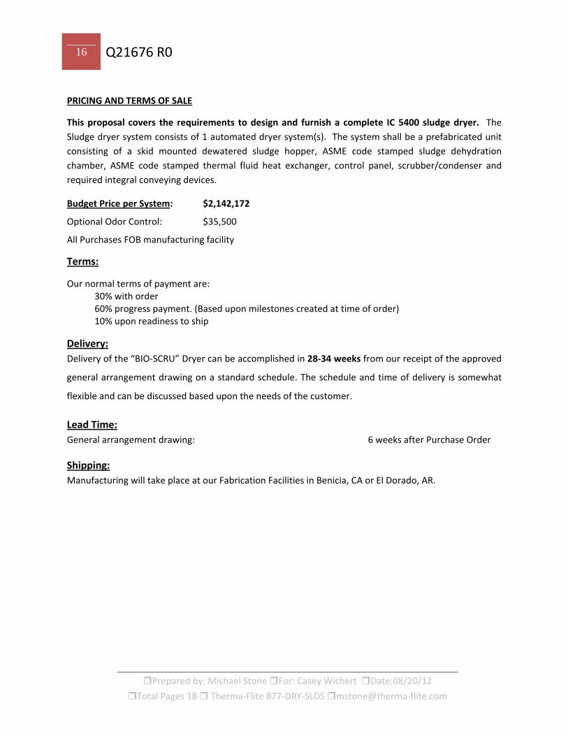
This proposal covers the requirements to design and furnish a complete IC 5400 sludge dryer. The
Sludge dryer system consists of 1 automated dryer system(s). The system shall be a prefabricated unit
consisting of a skid mounted dewatered sludge hopper, ASME code stamped sludge dehydration
chamber, ASME code stamped thermal fluid heat exchanger, control panel, scrubber/condenser and
required integral conveying devices.
Budget Price per System: $2,142,172
Optional Odor Control: $35,500
All Purchases FOB manufacturing facility
Terms:
Our normal terms of payment are: 30% with order 60% progress payment. (Based upon milestones created at time of order) 10% upon readiness to ship
Delivery:
Delivery of the “BIO‐SCRU” Dryer can be accomplished in 28‐34 weeks from our receipt of the approved
general arrangement drawing on a standard schedule. The schedule and time of delivery is somewhat
flexible and can be discussed based upon the needs of the customer.
Lead Time:
General arrangement drawing: 6 weeks after Purchase Order
Shipping:
Manufacturing will take place at our Fabrication Facilities in Benicia, CA or El Dorado, AR.
17 Q21676 R0
Prepared by: Michael Stone For: Casey Wichert Date:08/20/12
Total Pages 18 Therma‐Flite 877‐DRY‐SLDS mstone@therma‐flite.com
TERMS AND CONDITIONS OF SALE
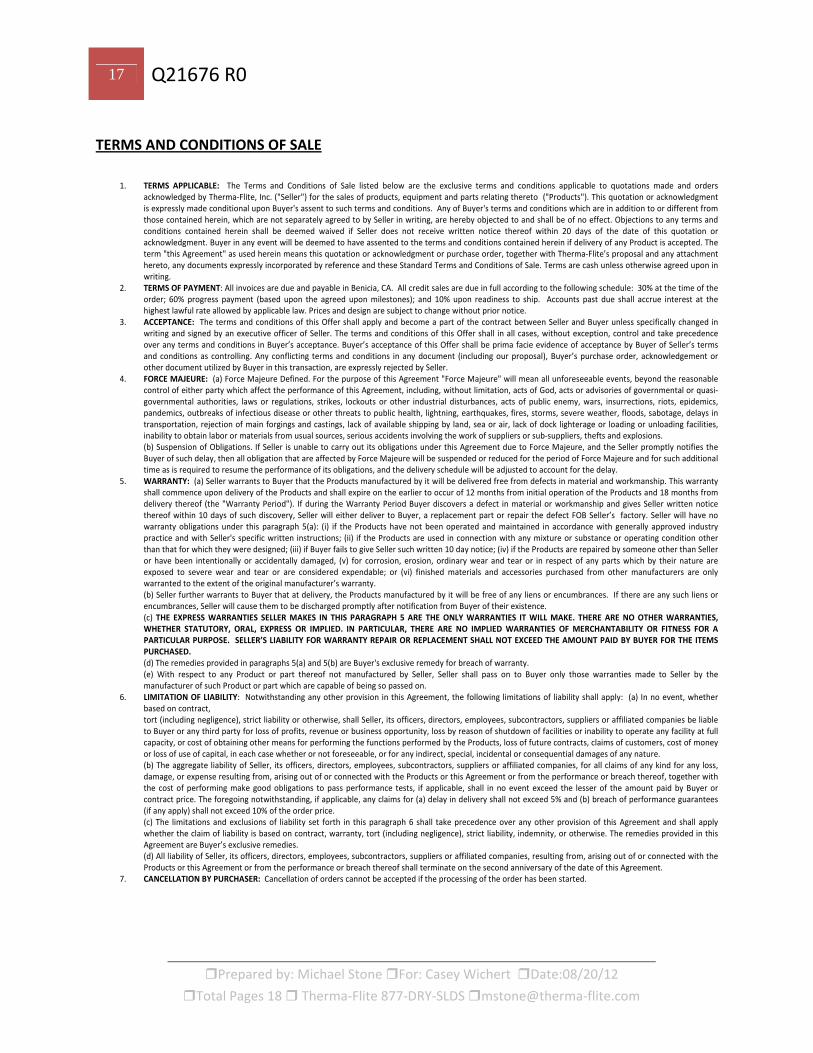
1. TERMS APPLICABLE: The Terms and Conditions of Sale listed below are the exclusive terms and conditions applicable to quotations made and orders acknowledged by Therma‐Flite, Inc. ("Seller") for the sales of products, equipment and parts relating thereto ("Products"). This quotation or acknowledgment is expressly made conditional upon Buyer's assent to such terms and conditions. Any of Buyer's terms and conditions which are in addition to or different from those contained herein, which are not separately agreed to by Seller in writing, are hereby objected to and shall be of no effect. Objections to any terms and conditions contained herein shall be deemed waived if Seller does not receive written notice thereof within 20 days of the date of this quotation or acknowledgment. Buyer in any event will be deemed to have assented to the terms and conditions contained herein if delivery of any Product is accepted. The term "this Agreement" as used herein means this quotation or acknowledgment or purchase order, together with Therma‐Flite’s proposal and any attachment hereto, any documents expressly incorporated by reference and these Standard Terms and Conditions of Sale. Terms are cash unless otherwise agreed upon in writing.
2. TERMS OF PAYMENT: All invoices are due and payable in Benicia, CA. All credit sales are due in full according to the following schedule: 30% at the time of the order; 60% progress payment (based upon the agreed upon milestones); and 10% upon readiness to ship. Accounts past due shall accrue interest at the highest lawful rate allowed by applicable law. Prices and design are subject to change without prior notice.
3. ACCEPTANCE: The terms and conditions of this Offer shall apply and become a part of the contract between Seller and Buyer unless specifically changed in writing and signed by an executive officer of Seller. The terms and conditions of this Offer shall in all cases, without exception, control and take precedence over any terms and conditions in Buyer’s acceptance. Buyer’s acceptance of this Offer shall be prima facie evidence of acceptance by Buyer of Seller’s terms and conditions as controlling. Any conflicting terms and conditions in any document (including our proposal), Buyer’s purchase order, acknowledgement or other document utilized by Buyer in this transaction, are expressly rejected by Seller.
4. FORCE MAJEURE: (a) Force Majeure Defined. For the purpose of this Agreement "Force Majeure" will mean all unforeseeable events, beyond the reasonable control of either party which affect the performance of this Agreement, including, without limitation, acts of God, acts or advisories of governmental or quasi‐governmental authorities, laws or regulations, strikes, lockouts or other industrial disturbances, acts of public enemy, wars, insurrections, riots, epidemics, pandemics, outbreaks of infectious disease or other threats to public health, lightning, earthquakes, fires, storms, severe weather, floods, sabotage, delays in transportation, rejection of main forgings and castings, lack of available shipping by land, sea or air, lack of dock lighterage or loading or unloading facilities, inability to obtain labor or materials from usual sources, serious accidents involving the work of suppliers or sub‐suppliers, thefts and explosions. (b) Suspension of Obligations. If Seller is unable to carry out its obligations under this Agreement due to Force Majeure, and the Seller promptly notifies the Buyer of such delay, then all obligation that are affected by Force Majeure will be suspended or reduced for the period of Force Majeure and for such additional time as is required to resume the performance of its obligations, and the delivery schedule will be adjusted to account for the delay.
5. WARRANTY: (a) Seller warrants to Buyer that the Products manufactured by it will be delivered free from defects in material and workmanship. This warranty shall commence upon delivery of the Products and shall expire on the earlier to occur of 12 months from initial operation of the Products and 18 months from delivery thereof (the "Warranty Period"). If during the Warranty Period Buyer discovers a defect in material or workmanship and gives Seller written notice thereof within 10 days of such discovery, Seller will either deliver to Buyer, a replacement part or repair the defect FOB Seller’s factory. Seller will have no warranty obligations under this paragraph 5(a): (i) if the Products have not been operated and maintained in accordance with generally approved industry practice and with Seller's specific written instructions; (ii) if the Products are used in connection with any mixture or substance or operating condition other than that for which they were designed; (iii) if Buyer fails to give Seller such written 10 day notice; (iv) if the Products are repaired by someone other than Seller or have been intentionally or accidentally damaged, (v) for corrosion, erosion, ordinary wear and tear or in respect of any parts which by their nature are exposed to severe wear and tear or are considered expendable; or (vi) finished materials and accessories purchased from other manufacturers are only warranted to the extent of the original manufacturer’s warranty. (b) Seller further warrants to Buyer that at delivery, the Products manufactured by it will be free of any liens or encumbrances. If there are any such liens or encumbrances, Seller will cause them to be discharged promptly after notification from Buyer of their existence. (c) THE EXPRESS WARRANTIES SELLER MAKES IN THIS PARAGRAPH 5 ARE THE ONLY WARRANTIES IT WILL MAKE. THERE ARE NO OTHER WARRANTIES, WHETHER STATUTORY, ORAL, EXPRESS OR IMPLIED. IN PARTICULAR, THERE ARE NO IMPLIED WARRANTIES OF MERCHANTABILITY OR FITNESS FOR A PARTICULAR PURPOSE. SELLER’S LIABILITY FOR WARRANTY REPAIR OR REPLACEMENT SHALL NOT EXCEED THE AMOUNT PAID BY BUYER FOR THE ITEMS PURCHASED. (d) The remedies provided in paragraphs 5(a) and 5(b) are Buyer's exclusive remedy for breach of warranty. (e) With respect to any Product or part thereof not manufactured by Seller, Seller shall pass on to Buyer only those warranties made to Seller by the manufacturer of such Product or part which are capable of being so passed on.
6. LIMITATION OF LIABILITY: Notwithstanding any other provision in this Agreement, the following limitations of liability shall apply: (a) In no event, whether based on contract, tort (including negligence), strict liability or otherwise, shall Seller, its officers, directors, employees, subcontractors, suppliers or affiliated companies be liable to Buyer or any third party for loss of profits, revenue or business opportunity, loss by reason of shutdown of facilities or inability to operate any facility at full capacity, or cost of obtaining other means for performing the functions performed by the Products, loss of future contracts, claims of customers, cost of money or loss of use of capital, in each case whether or not foreseeable, or for any indirect, special, incidental or consequential damages of any nature. (b) The aggregate liability of Seller, its officers, directors, employees, subcontractors, suppliers or affiliated companies, for all claims of any kind for any loss, damage, or expense resulting from, arising out of or connected with the Products or this Agreement or from the performance or breach thereof, together with the cost of performing make good obligations to pass performance tests, if applicable, shall in no event exceed the lesser of the amount paid by Buyer or contract price. The foregoing notwithstanding, if applicable, any claims for (a) delay in delivery shall not exceed 5% and (b) breach of performance guarantees (if any apply) shall not exceed 10% of the order price. (c) The limitations and exclusions of liability set forth in this paragraph 6 shall take precedence over any other provision of this Agreement and shall apply whether the claim of liability is based on contract, warranty, tort (including negligence), strict liability, indemnity, or otherwise. The remedies provided in this Agreement are Buyer’s exclusive remedies. (d) All liability of Seller, its officers, directors, employees, subcontractors, suppliers or affiliated companies, resulting from, arising out of or connected with the Products or this Agreement or from the performance or breach thereof shall terminate on the second anniversary of the date of this Agreement.
7. CANCELLATION BY PURCHASER: Cancellation of orders cannot be accepted if the processing of the order has been started.
18 Q21676 R0
Prepared by: Michael Stone For: Casey Wichert Date:08/20/12
Total Pages 18 Therma‐Flite 877‐DRY‐SLDS mstone@therma‐flite.com
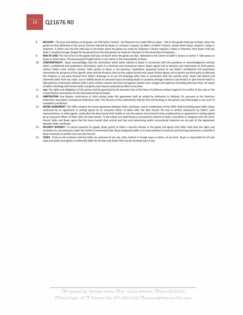
8. DELIVERY: The price and delivery of all goods, are FOB Seller’s factory. All shipments are made FOB our plant. Title to the goods shall pass to Buyer when the goods are duly delivered to the carrier (Carrier) selected by Buyer or, at Buyer's request, by Seller, at Seller’s factory, except where Buyer requests a delay in shipment, in which case the title shall pass to the Buyer when the goods are ready for shipment. If Buyer requests a delay in shipment, then Buyer shall pay Seller’s standard storage charges for the period from the date goods are ready for shipment to the actual date of shipment.
9. RISK OF LOSS: The risk of loss to the goods shall pass to Buyer when the goods are duly delivered to the Carrier at Seller’s factory or earlier if title passes to Buyer as listed above. The processing of freight claims or loss claims is the responsibility of Buyer.
10. CONFIDENTIALITY: Buyer acknowledges that the information which Seller submits to Buyer in connection with this quotation or acknowledgment includes Seller's confidential and proprietary information, both of a technical and commercial nature. Buyer agrees not to disclose such information to third parties without Seller's prior written consent. Seller grants to Buyer a non‐exclusive, royaltyfree, perpetual license to use Seller’s confidential and proprietary information for purposes of this specific order and the Products that are the subject hereof only. Buyer further agrees not to permit any third party to fabricate the Products or any parts thereof from Seller's drawings or to use the drawings other than in connection with this specific order. Buyer will defend and indemnify Seller from any claim, suit or liability based on personal injury (including death) or property damage related to any Product or part thereof which is fabricated by a third party without Seller's prior written consent and from and against related costs, charges and expenses (including attorneys fees). All copies of Seller's drawings shall remain Seller's property and may be reclaimed by Seller at any time.
11. Law: The rights and obligations of the parties shall be governed by the domestic laws of the State of California without regard to its conflict of law rules or the United Nations Convention for the International Sale of Goods.
12. ARBITRATION: Any dispute, controversy or claim arising under this agreement shall be settled by arbitration in Oakland, CA, pursuant to the American Arbitration Association Commercial Arbitration rules. The decision of the arbitrator(s) shall be final and binding on the parties and enforceable in any court of competent jurisdiction.
13. ENTIRE AGREEMENT: This Offer contains the entire agreement between Seller and Buyer, and no modification of this Offer shall be binding upon Seller unless evidenced by an agreement in writing signed by an executive officer of Seller after the date hereof. No oral or written statements by Seller’s sales representatives, or other agents, made after the date hereof shall modify or vary the express terms hereof unless evidenced by an agreement in writing signed by an executive officer of Seller after the date hereof. To the extent any advertising or promotional material of Seller contradicts or disagrees with the terms hereof, Seller and Buyer agree that the terms hereof shall control and that such advertising and/or promotional materials are not part of the Agreement between Seller and Buyer.
14. SECURITY INTEREST:. To secure payment for goods, Buyer grants to Seller a security interest in the goods and agrees that Seller shall have the rights and remedies of a secured party under the Uniform Commercial Code. Buyer designates Seller as its attorneyinfact to execute any financing statements on behalf of Buyer necessary to perfect such security interest.
15. TAXES: Prices on the products sold buy Seller are exclusive of any city, state, federal or foreign taxes or duties, of any kind. Buyer is responsible for all such taxes and duties and agrees to indemnify Seller for all taxes and duties that may be assessed upon it due
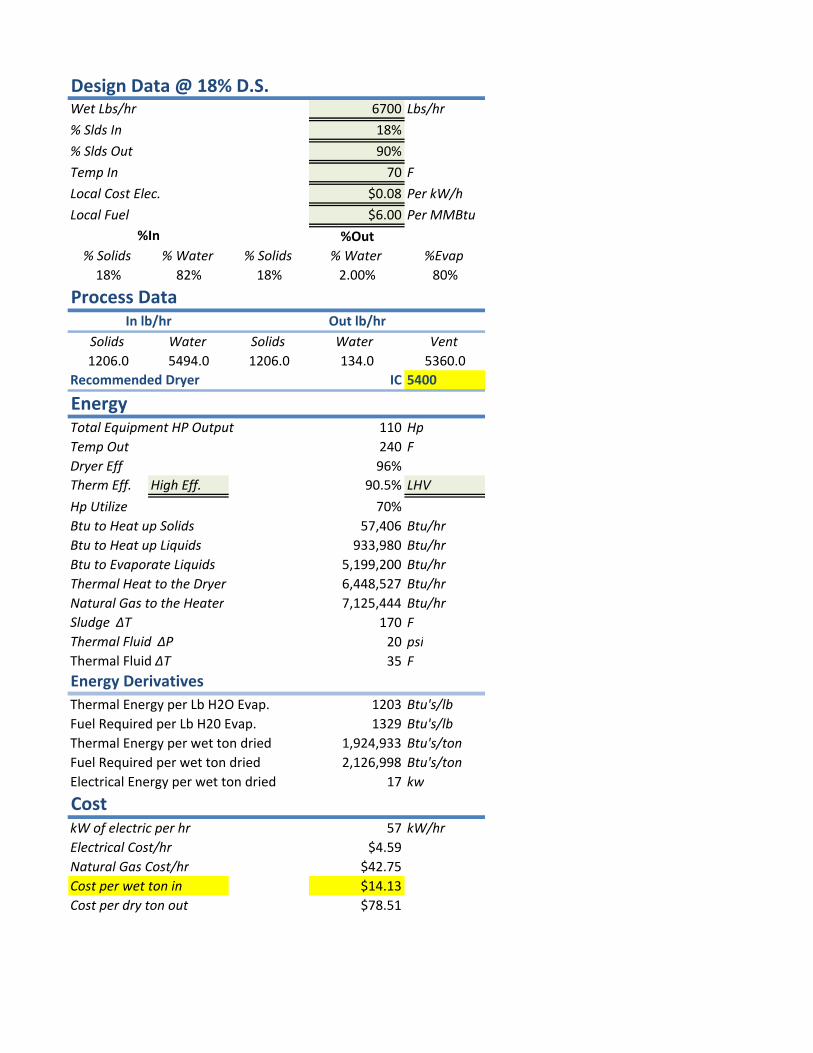
Design Data @ 18% D.S.Wet Lbs/hr 6700 Lbs/hr
% Slds In 18%
% Slds Out 90%
Temp In 70 F
Local Cost Elec. $0.08 Per kW/h
Local Fuel $6.00 Per MMBtu
% Solids % Water % Solids % Water %Evap
18% 82% 18% 2.00% 80%
Process Data
Solids Water Solids Water Vent
1206.0 5494.0 1206.0 134.0 5360.0
Recommended Dryer IC 5400
Total Equipment HP Output 110 Hp
Temp Out 240 F
Dryer Eff 96%
Therm Eff. High Eff. 90.5% LHV
Hp Utilize 70%
Btu to Heat up Solids 57,406 Btu/hr
Btu to Heat up Liquids 933,980 Btu/hr
Btu to Evaporate Liquids 5,199,200 Btu/hr
Thermal Heat to the Dryer 6,448,527 Btu/hr
Natural Gas to the Heater 7,125,444 Btu/hr
Sludge ∆T 170 F
Thermal Fluid ∆P 20 psi
Thermal Fluid ∆T 35 F
Energy Derivatives
Thermal Energy per Lb H2O Evap. 1203 Btu's/lb
Fuel Required per Lb H20 Evap. 1329 Btu's/lb
Thermal Energy per wet ton dried 1,924,933 Btu's/ton
Fuel Required per wet ton dried 2,126,998 Btu's/ton
Electrical Energy per wet ton dried 17 kw
CostkW of electric per hr 57 kW/hr
Electrical Cost/hr $4.59
Natural Gas Cost/hr $42.75
Cost per wet ton in $14.13
Cost per dry ton out $78.51
Energy
In lb/hr Out lb/hr
%In %Out


Appendix B ANDRITZ Budgetary Information #1305144, May 31,2013
ANDRITZ SEPARATION INC.
1010 Commercial Blvd. S. Arlington, Texas 76001
Tel. (817) 465-5611 Fax (817) 468-3961
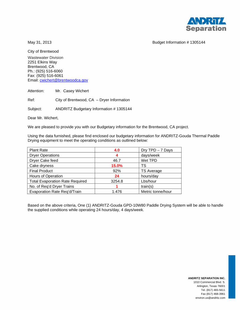
May 31, 2013 Budget Information # 1305144 City of Brentwood Wastewater Division 2251 Elkins Way Brentwood, CA Ph.: (925) 516-6060 Fax: (925) 516-6061 Email: [email protected] Attention: Mr. Casey Wichert Ref: City of Brentwood, CA – Dryer Information Subject: ANDRITZ Budgetary Information # 1305144 Dear Mr. Wichert, We are pleased to provide you with our Budgetary information for the Brentwood, CA project. Using the data furnished, please find enclosed our budgetary information for ANDRITZ-Gouda Thermal Paddle Drying equipment to meet the operating conditions as outlined below: Plant Rate 4.0 Dry TPD – 7 Days Dryer Operations 4 days/week Dryer Cake feed 46.7 Wet TPD Cake dryness 15.0% TS Final Product 92% TS Average Hours of Operation 24 hours/day Total Evaporation Rate Required 3254.8 Lbs/hour No. of Req’d Dryer Trains 1 train(s) Evaporation Rate Req’d/Train 1.476 Metric tonne/hour
Based on the above criteria, One (1) ANDRITZ-Gouda GPD-10W80 Paddle Drying System will be able to handle the supplied conditions while operating 24 hours/day, 4 days/week.
ANDRITZ SEPARATION INC.
1010 Commercial Blvd. S. Arlington, Texas 76001
Tel. (817) 465-5611 Fax (817) 468-3961
I will be pleased to discuss your project and the ANDRITZ budgetary information at your earliest convenience. Thank you for this opportunity and your interest in ANDRITZ products and services. Sincerely, Todd R. Pratt SEPARATION Region North America North America Sales Manager – Thermal Drying Systems ANDRITZ Separation Inc. 1010 Commercial Blvd S. Arlington, TX 76001 Direct Phone: 817-375-4490 Direct Fax: 817-375-6490 [email protected] www.andritz.com
Encl.: ANDRITZ-Gouda Budgetary Information # 1305144 (BQ13;0530)
ANDRITZ Standard Terms and Conditions of Sale
cc: Bruce SoRelle – ANDRITZ Regional Sales Manager
Dear Mr. Casey Wichert; I am pleased to be able to offer you this information on our sludge dryer Model GPD 10W80 and its auxiliary equipment. As you find additional questions that need to be answered, please feel free to contact me for assistance. Yours sincerely, Andritz-Gouda Processing Solutions Mark McKee Area Manager – North America GMF-Gouda America, Inc.
Andritz-Gouda 9201 NW 78th ST Weatherby Lake, MO 64152 United States
City of Brentwood
Tel. Fax
(816) 505-9900 (816) 505-9995
Email INTERNET
[email protected] WWW.GMFGOUDA.COM
Date Our ref. Subject
May 30, 2013 1305144 (BQ13;0530 MMk) Budget Quotation Sludge Drying Line
CLIENT QUOTE
All tendersgeneral co
CON
1 D11
2 S22
3 S33
3333333
4 IN444
5 P
6 T
NAME: City NR.: BQ13,
s & contracts foonditions.
NTENT
DESIGN PR.1 ......... Pro.2 ......... Plan
SUMMARY .1 ......... Deli.2 ......... Not
SCOPE OF S.1 ......... Wet.2 ......... GM
3.2.1 3.2.2
.3 ......... Dry
.4 ......... Dry
.5 ......... Vap
.6 ......... The
.7 ......... Auto
.8 ......... Doc
.9 ......... Plat
NSTALLAT.1 ......... Sup.2 ......... Ere.3 ......... Trai
PACKING A
ERMS AND
of Brentwoo0530
r the performan
OCESS PAcess Paramnt consump
PROCESSivery time ..included in
SUPPLY ---t sludge intaF-Gouda P
Machine sThe dryer
sludge coosludge han
por condensermal oil heaomation ....cumentationtform & Sca
TION & COMpervision of ction and coining .........
AND TRANS
D CONDITIO
od, CA
nce of deliveries
ARAMETERmeter per Drption (for ref
ING LINE --..................
n this quotat
----------------ake section
Paddle Dryespecifications ...construction ....
oling ...........ndling .........sing ...........ater .............................n ................affolding .....
MMISSIONIerection anommissioni..................
SPORT -----
ONS --------
and service ou
RS ------------rying Line ..ferred scope
----------------..................tion ............
---------------- .................r ..............................................................................................................................................................................................
ING ----------nd commissng ...............................
----------------
----------------
utside the Nethe
---------------..................e only) .......
---------------....................................
---------------....................................................................................................................................................................................................................
---------------sioning ...........................................
---------------
---------------
erlands are gove
----------------....................................
----------------....................................
----------------....................................................................................................................................................................................................................
----------------......................................................
----------------
----------------
erned by the Org
----------------....................................
----------------....................................
----------------..................................................................................................................................................................................................................
----------------......................................................
----------------
----------------
galime
-------- 3 .......... 3 .......... 4
-------- 5 .......... 5 .......... 5
-------- 6 .......... 6 .......... 6 ............... 6 ............... 7 .......... 8 .......... 9 .......... 9 .......... 9 ........ 10 ........ 10 ........ 10
------- 10 ........ 11 ........ 11 ........ 11
------- 11
------- 12
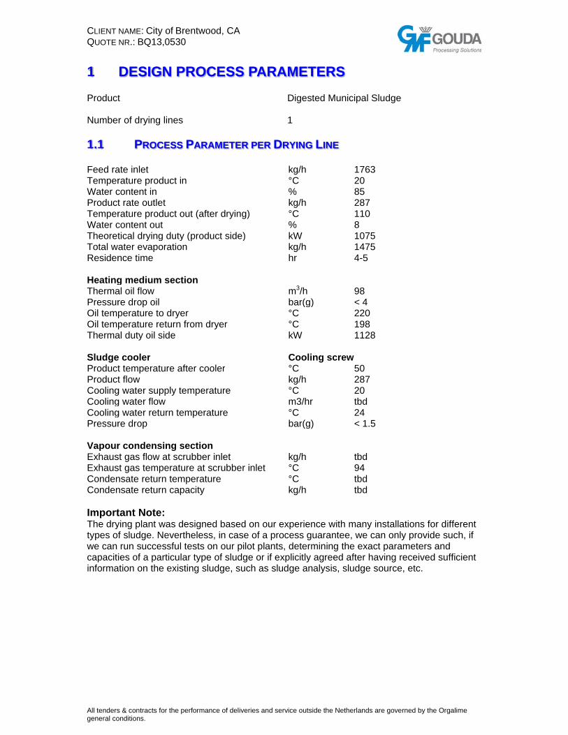
CLIENT QUOTE
All tendersgeneral co
1 Product
Numbe
1.1 Feed raTemperWater cProductTemperWater cTheoretTotal wResiden HeatingThermaPressurOil temOil temTherma SludgeProductProductCoolingCoolingCoolingPressur VapourExhausExhausCondenConden ImportThe drytypes ofwe can capacitinforma
NAME: City NR.: BQ13,
s & contracts foonditions.
DESIGN
t
r of drying l
PROCE
ate inlet rature producontent in t rate outletrature producontent out tical drying ater evapornce time
g medium sal oil flow re drop oil perature to perature retal duty oil si
e cooler t temperatut flow
g water suppg water flowg water reture drop
r condensist gas flow ast gas tempensate returnnsate return
tant Note:ying plant wf sludge. Nerun succesies of a par
ation on the
of Brentwoo0530
r the performan
N PROC
ines
ESS PARA
uct in
t uct out (afte
duty (produration
section
dryer turn from drde
ure after coo
ply temperaw
rn temperat
ng sectionat scrubber erature at sn temperatun capacity
was designe
everthelessssful tests orticular type existing slu
od, CA
nce of deliveries
CESS PA
AMETER PE
er drying)
uct side)
ryer
oler
ature
ture
n inlet
scrubber inlere
d based ons, in case ofon our pilot p
of sludge oudge, such a
and service ou
ARAME
Dige 1
ER DRYING
kg/h°C % kg/h°C % kWkg/hhr m3/hbar(g°C °C kW Coo°C kg/h°C m3/h°C bar(g kg/h
et °C °C kg/h
our experief a process plants, deteor if explicitlas sludge a
utside the Nethe
ETERS
ested Munic
G LINE
h g)
oling screw
hr
g)
ence with mguarantee,
ermining they agreed af
analysis, slu
erlands are gove
cipal Sludge
1763 20 85 287 110 8 10751475 4-5
98 < 4220 198 1128
w 50 287 20 tbd 24 < 1.5
tbd 94 tbd tbd
many installawe can onl
e exact parafter having rudge source
erned by the Org
e
ations for dly provide sameters andreceived sue, etc.
galime
ifferent such, if d ufficient

CLIENT QUOTE
All tendersgeneral co
1.2
ConsumDesign InstalledConsumTotal co Energy OptionaHot wat SpecifiConsumConsumConsumConsum Yearly OperatiTotal prRequirePotentia
* - D
All figu
NAME: City NR.: BQ13,
s & contracts foonditions.
PLANT
mption at ncapacity wed electrical med electriconsumed he
source
al heat recoter at 85ºC
c energy cmed heatingmed heatingmed electricmed electric
consumptonal time rocessed wed supplemal heat reco
Depends on
ures are ap
of Brentwoo0530
r the performan
T CONSUM
nominal caet sludge power
cal power eating powe
overy from d
consumptiog power/ weg power / tocal power / wcal power / t
tion at nom
et sludge entary heat
overy of hot
n the situatio
proximate
od, CA
nce of deliveries
MPTION (FO
apacity
er dryer
drying
on at dryeret ton sludgeon evaporatewet ton sludton evapora
minal capac
ting power p water per y
on on site.
figures un
and service ou
OR REFERR
r e* ed water* dge* ated water*
city
per year year
ntil the deta
utside the Nethe
RED SCOP
ailed plant
erlands are gove
PE ONLY)
kg/h kW kW kW Therma kW kWh kWh kWh kWh h/yeart/yearkWh kWh
lay-out is k
erned by the Org
1763 tbd tbd 1128
al oil tbd 640 765 tbd tbd 5000 8813 tbd tbd
known.
galime
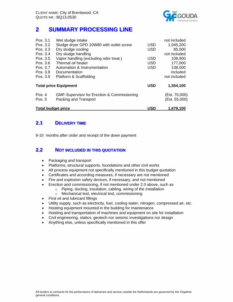
CLIENT QUOTE
All tendersgeneral co
2 Pos. 3.1Pos. 3.2Pos. 3.3Pos. 3.4Pos. 3.5Pos. 3.6Pos. 3.7Pos. 3.8Pos. 3.9 Total p Pos. 4 Pos. 5 Total b
2.1 9-10 m
2.2
• • • • • •
• • • • • •
NAME: City NR.: BQ13,
s & contracts foonditions.
SUMMA
1 Wet slu2 Sludge3 Dry slu4 Dry slu5 Vapor 6 Therma7 Automa8 Docum9 Platform
price Equip
GMF-SPackin
budget pric
DELIV
months after
NOT IN
Packaging Platforms, sAll processCertificatesFire and exErection an
o Pipio Mec
First oil andUtility suppHoisting eqHoisting anCivil engineAnything el
of Brentwoo0530
r the performan
ARY PR
udge intakee dryer GPDudge coolingudge handlinhandling (eal oil heateration & Inst
mentation m & Scaffol
ment
Supervisor fg and Tran
e
ERY TIME
r order and
NCLUDED I
and transpostructural su
s equipments and accordxplosion safnd commissing, ductingchanical tesd lubricant fply, such as quipment mond transporteering, statilse, unless
od, CA
nce of deliveries
ROCESS
e D 10W80 wig ng
excluding odr trumentation
lding
for Erection sport
receipt of th
IN THIS QU
ort upports, fout not specifiding measufety devicessioning, if nog, insulationst, electricalfillings electricity, founted in thtation of macs, geotechspecifically
and service ou
SING LIN
th outlet sc
dor treat.)
n
& Commis
he down pa
UOTATION
undations acally mentio
ures, if neces, if necessaot mentione, cabling, wl test, comm
fuel, coolinghe building fachines andh nor seismmentioned
utside the Nethe
NE
rew
sioning
yment
and other civoned in thisessary are nary, and noted under 2.0wiring of the missioning
g water, nitrfor mainten equipmentic investiga in this offe
erlands are gove
USDUSD
USDUSDUSD
USD
USD
vil works s budget quonot mentiont mentioned0 above, suinstallation
rogen, comance t on site for
ations nor der
erned by the Org
not include1,045,20
85,00not include
108,90177,00138,00include
not include
1,554,10
(Est. 70,00(Est. 55,00
1,679,10
otation ed
d ch as
pressed air
installationesign
galime
d 0 0 d 0 0 0 d d
0
00) 00)
0
r, etc.
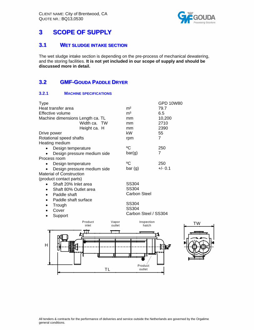
CLIENT QUOTE
All tendersgeneral co
3
3.1 The weand thediscuss
3.2 3.2.1 Type Heat traEffectivMachin Drive poRotatioHeating
• •
Process• •
Materia(produc
• • • • • • •
H
NAME: City NR.: BQ13,
s & contracts foonditions.
SCOPE
WET S
et sludge inte storing facsed more i
GMF-
MACH
ansfer area ve volume e dimensio ower nal speed sg medium Design temDesign pres room Design temDesign pre
al of Construct contact paShaft 20% Shaft 80% Paddle shaPaddle shaTrough Cover Support
of Brentwoo0530
r the performan
E OF SU
SLUDGE IN
ake sectioncilities. It is n detail.
GOUDA P
HINE SPECIF
ns Length c Width ca Height c
shafts
mperature ssure medi
mperature ssure mediuction arts) Inlet area Outlet area
aft aft surface
Product inlet
od, CA
nce of deliveries
UPPLY
NTAKE SEC
n is dependinot yet inc
PADDLE D
ICATIONS
ca. TL a. TW ca. H
um side
um side
a
Vapout
TL
and service ou
CTION
ing on the pcluded in o
RYER
m² m³ mm mm mm kW rpm ºC bar(g) ºC bar (g SS304SS304Carbo SS304SS304Carbo
por tlet
utside the Nethe
pre-processur scope o
)
g)
4 4
on Steel
4 4
on Steel / S
Inspection hatch
Product outlet
erlands are gove
s of mechanof supply an
GPD 10W879.7 6.5 10,200 2710 2390 55 7 250 7 250 +/- 0.1
S304
erned by the Org
nical dewatend should
80
TW
galime
ering, be
W
CLIENT NAME: City of Brentwood, CA QUOTE NR.: BQ13,0530
All tenders & contracts for the performance of deliveries and service outside the Netherlands are governed by the Orgalime general conditions.
3.2.2 THE DRYER CONSTRUCTION General The GMF Paddle dryer consists of a jacketed trough and two shafts with hollow paddles. On the trough is a cover with the inlet for the product to be dried. The product is dried by heat transfer with the heating medium which is flowing trough the shafts, paddles and jacket. The dried product is removed from the discharge chute via a shaftless spiral screw conveyor. The exhaust vapours leave the dryer through an exhaust outlet on the cover. The absence of air during the drying process results in a very safe operation due to lowest oxygen content, a small and compact odour treatment and it offers the possibility of a heat recovery system in the vapour condensing unit due to the high dew point of the off-gas. Trough The trough is omega shaped with a jacket. The product is fed at one end of the machine and will be transported by gravity, under a slight angle of the trough, to the outlet of the machine at the other end. During tee residence time of the product in the machine, a perfect plug flow is maintained, guaranteeing perfect uniform product quality. The product level inside the machine is secured by an adjustable overflow wear. Overflow weir at the product outlet side has manually operated emptying valves at the bottom of the product removal before a production stop. Product outlet chute at the bottom of the trough has a rectangular flange to connect to the downstream equipment. Discharge conveyor A horizontal spiral screw conveyor is mounted underneath the rectangular outlet flange of the discharge chute, to remove the product from the trough. The spiral screw conveyor has two bottom outlets, one on each end of the conveyor. In combination with the bi-directional rotation of the screw conveyor, the product can be transported to either one of these product outlets. One of the product outlets is connected to the further transport system, for post-processing of the dried sludge. The other outlet is an emergency outlet for off-spec product, in case of a process hick-up in the dryer. Shafts The dryer has two hollow shafts with hollow wedge-shaped paddles arranged in staggered position. Heating medium is introduced at one side of the shafts and flows in parallel through the paddles. The paddles are wedge shaped for optimal contact with the product and consequently good heat transfer at the product side as well. The heating medium leaves the shafts at the same side as it comes in. To protect against abrasion, the last 70% of the paddles will be coated with our HVOF tungsten carbide abrasion-resistant coating. Cover On the dust tight cover are the product inlet, the vapour outlet, two inspection ports and a man hole. Together with the upper part of the trough a gas/vapour dome is created. The cover can be optionally heat traced to prevent any risk of condensation. Sweep gas can be introduced through nozzles at the product inlet- and outlet side. Shaft seals The main shaft seals are effected with stuffing boxes. The stuffing boxes are flexibly connected with the trough endplates, such that they can follow small movements of the shafts and still maintain tightness. On the shafts wear sleeves at the sealing area prevent shaft damage by abrasion. The wear sleeves have a special hard surface (ceramic) layer. The stuffing boxes have a lantern ring for a gas purge. Bearings The bearings are roller bearings with oil lubrication including oiltank, filter, pump, etc.
CLIENT QUOTE
All tendersgeneral co
RotarieThe hearotary o Drive uThe shaspur gevariatio StandaThe foll
• •
• Frame The fraendplatcompaccompen AutomaThe aut
3.3 The prosafe sto The proan indirThere wenter anauger. TenteringthroughThe scr Dry sluModel QuantitLength Screw dQuantitDrive poCoolingDesign Design Materia
NAME: City NR.: BQ13,
s & contracts foonditions.
es at transfer m
on one side
unit aft is driven
ears which en.
ard instrumowing standControl of tThermowel(excluding Control on
me is consttes of the roct and sandnsate for the
ation tomation of
DRY S
oduct dischaoring and ha
oduct discharect cooled will be no cond exit the fThe trough g the atmosh a flanged crew will use
udge coole
y
diameter y for rotary ower
g medium pressure mtemperatur
al of constru
of Brentwoo0530
r the performan
medium is iof the shaft
by an E-mensure iden
mentation / dard instrumthe drive bylls for produPT 100) the lubricat
tructed fromough. The frwich designermal expa
the entire d
LUDGE CO
arged from andling con
arged from screw conv
ontaminatioflanged conwill utilize a
sphere arouconnection a variable
r
joints
medium sidere uction
od, CA
nce of deliveries
ntroduced it.
otor with a tical rotatio
sensors mentation isy means of auct tempera
tion of the b
m a steel parame gives n. At the pronsion.
drying line is
OOLING
the dryer neditions.
the dryer faveyor, usingn of the coo
nnections ofa formed flaund the cool
for further hfrequency c
e
and service ou
nto – and re
shaft mounnal speed.
s included inan Emotron
ature measu
bearings inc
inted sandwthe requiredoduct outlet
s mentioned
eeds to be
alls directly g circulatingoling water f the cooler
ange with boler. The coohandling. control to va
GCS 4Unit mm mm unit kW Bar (gºC Carbo
utside the Nethe
emoved fro
ted gearboxSpeed is fix
n the scopen (in the conurement, po
cluding eme
wich construd rigidity to t side the st
d as a sepa
cooled dow
via a flange non-potablwith the proat the troug
olted top cooled produc
ary the ope
4S8
g)
on and Stain
erlands are gove
m – the sha
x. Betweenxed and doe
e of supply: ntrol cabinetositioned on
ergency sign
uction by elthe machin
tructure can
arate item in
wn to below
ed connectiole water as oduct. The cgh and at th
over to prevect leaves the
rating spee
1 5000 300 2 2.2 Min 2.5 120 nless steel
erned by the Org
aft via the s
the shafts es not requ
t the trough
nal.
ongations one because n slide to
n this quota
50 oC to en
on in the cocooling me
cooling wathe rotary of ent dust froe screw coo
d of the coo
galime
ame
are ire
of the of its
tion.
nsure
over into edia. er will the m
oler
oler.
CLIENT QUOTE
All tendersgeneral co
3.4
The drielocal sitof this q
3.5 Since thamountevaporafeed, anThe ducconden Wet ScThe vapcondendryer. In the ccontact must beThe conover dro CondenDiameteHeight cMateriaWeight Capacit ExhausThe remDesign Power
3.6 We will coils, incapableoil pum
NAME: City NR.: BQ13,
s & contracts foonditions.
DRY S
ed and cootuation diffequotation.
VAPOR
his drying ct of outlet gaated water fnd anythingcting betwesation and
crubber syspors and reser/cooler.
condenser uwith spray
e drained bandenser unoplets of the
nser er condenscondenser
al of constru(not emerg
ty spray pum
st Fan maining gastemperatur
THERM
supply an Anstead of thee of burningp and oil co
of Brentwoo0530
r the performan
LUDGE HA
led sludge merent types o
R CONDEN
oncept useas to be trefrom the pro
g that escapeen dryer an
clogging of
stem maining fineThis, so ca
unit the vapowater whicack to WWTit is equippee water.
er
uction gency!) mp
sses (non-core
MAL OIL HE
ASI-type thee more com
g natural gasooler. Size –
od, CA
nce of deliveries
ANDLING
must be conof conveyor
NSING
s no sweepated is as moduct, a sm
ped from thend scrubberf the duct.
es coming falled spray c
ors, at a temh has a temTP. The vaped with a hi
mmmm kg m3/h
ondensable°CkW
EATER
ermal oil hemmon and les. System w– 2,500,000
and service ou
nveyed to thrs can be ch
p gas to remminimal as p
mall amount e product wr should be
from the drycondenser,
mperature omperature opor flow is mgh efficienc
100700AIS40050
es) of the wetbd2
eater, with 8ess efficientwill be comp0 btu.
utside the Nethe
he dry-prodhosen. Thes
move the vapossible. It of air which
while drying.insulated in
yer will be tcondenses
of approx. 9f max 75-80
maintained cy demister
0000 SI 316 00
et scrubber
88% efficient helical-typplete with a
erlands are gove
duct storagese conveya
pors from thbasically co
h might com
n order to pr
reated in a the vapors
95°C, are co0°C. Condeby an exhain order to
r are sent ou
ncy, having pe heaters. Butomation,
erned by the Org
e. Dependinances are no
he dryer, thonsists only
me from the
revent heat
direct s coming fro
ondensed byensate and sust fan. prevent car
ut by a fan.
serpentine Burner will oil expansio
galime
ng on ot part
he y of the
product
t losses,
om the
y direct solids
rrying
heating be on tank,
CLIENT QUOTE
All tendersgeneral co
3.7
The plaThis pro
• • • • •
•
3.8 Consist
• • • • • • • • •
• • ** d(twotime
IMPOR
3.9
By clien 4
Where installat
NAME: City NR.: BQ13,
s & contracts foonditions.
AUTOM
ant will be eqoposal inclu
Coated stSafety insAll requireDrawings Coated stIn the sammust be pTracking s
DOCU
ting of General arrFoundationP&I DiagraFunctional Operation aDeclarationPressure veComplianceManual withproceduresSpare partsLubricationocumentati
o) weeks afte.
RTANT: We
PLATF
nt.
INSTAL
possible, pation time on
of Brentwoo0530
r the performan
MATION
quipped witudes: teel control strumentatioed external and specs
teel cabinetme cabinetsplaced in a ssystem for a
MENTATIO
rangement n drawing** m** descriptionand Maintenn of Incorpoessel docume with ATEXh operatings, documents list instructionon for apprter receipt o
do not prov
FORM & S
LLATION
arts will be n site. On si
od, CA
nce of deliveries
th a central
panels withon and ememonitoring for MCC s (MCC) wi
s in the PLCsafe part of all main par
ON
drawing**
** nance Instr
oration acc. mentation X-certificatio instructiontation of the
s oval is to beor earlier in
vide manufa
CAFFOLDI
N & COM
shipped, prte, the follo
and service ou
control cab
h touch screergency rout
will be mad
th all the soC will be hou
the buildingrameters.
uctions EC 06/42 w
on (if applics, safety ase most impo
e returned tcase this w
acturing dra
ING
MMISSI
re-assemblewing works
utside the Nethe
binet with PL
een for modtines de available
oft starters aused in a seg.
with risk ana
cable) acc. tspects, mainortant mech
to us with cowould be req
awings.
IONING
ed to reduces will be exe
erlands are gove
LC and a se
el control a
e
and frequeneparate part
alysis (if app
to safety contenance an
hanical and
omments, ifquired in vie
e the requirecuted:
erned by the Org
eparate MC
and visualiza
ncy controllet; these cab
plicable)
oncept nd cleaningelectrical pa
f any, withinew of the de
red amount
galime
CC.
ation
ers. binets
g arts
n 2 elivery
of
CLIENT QUOTE
All tendersgeneral co
4.1
GMF refollowinprepara
-
-
- Expsha-
-
- -
-
4.2
Executiinsulatiocustomdifferenknown basis fo
4.3 Trainingmaintaiplant. U 5
The masuitableinvoiced
NAME: City NR.: BQ13,
s & contracts foonditions.
SUPER
ecommendsng timetableation work oSupervisionpiece onto SupervisioncondensingInstallation
pected Durafts or parall2 - 4 weeksSupervisor 1 - 2 weeksup/expansi2 weeks of Supervisionprocess/elePerformancsufficient slprotocol.
ERECT
ng all ereon, piping er or organ
nt skills (memore in de
or a more de
TRAIN
g can be pning it. Tra
Upon reques
PACKIN
achine partse for re-loadd to Buyer b
of Brentwoo0530
r the performan
RVISION O
s to providee and workfon-site and n of assemthe foundatn of placing equipmenof small loo
ation: 3 weelel). s of final woshould be
s of cold anon of dryersfinal work b
n of Commiectrical). – Hce test: upoludge of ste
TION AND
ection and and cablinized by a th
echanics, wetail, a cometailed calc
ING
provided, tining will tast the trainin
NG AND
s and/or accding or storabased on ac
od, CA
nce of deliveries
F ERECTIO
e Supervisilow was dislocal condit
mbly of dryetion g cooling st onto foundose parts oneks with 1 -
ork to be dopresent cand hot testins. 1 GMF-Sby customessioning: T
Here a prelion request, oeady (digest
COMMISSI
commissiong. Typicallyhird party wwelders, elemmissioning
ulation of th
o instruct ake place dng period ca
D TRANS
cessories wage. Transpctual cost, u
and service ou
ON AND CO
on during escussed andtions: er outside th
screw, scredation. n the dryer 2 GMF Sup
ne by custon be decideg incl. funct
Supervisor iser (insulationypically 2 wminary acceonce the opted) quality
IONING
oning work y this workith local peoctricians, emaster pla
he erection
the operatoduring the ean be exten
SPORT
will be packeport is not inunless othe
utside the Nethe
OMMISSION
erection and targeted,
he building
eener, fine
and coolerpervisors (in
omer (pipingd during thetional testins strongly ren of equipm
weeks with 2eptance properation on is available
on-site, ink is done ople. The w
etc.) at diffean should band commi
ors on opeerection andnded.
T
ed for truck ncluded in thrwise speci
erlands are gove
NING
nd commissbut is howe
and placin
return con
n case work
g, ducting, ce project. g and first hecommende
ment etc.) 2 GMF-staffotocol shouthe WWTP
e. Signing o
ncluding hby the gen
work requireerent times.be createdssioning co
erating the d commissio
transport. This quotatiofied.
erned by the Org
sioning periever, depen
ng the drye
nveyor and
k should be
cabling) If a
heating-ed be prese
f (mechanicld be signed
P has stabilizof final acce
oisting equneral contra
es several p. Once the which serv
ost.
plant, as oning perio
This packingon and will b
galime
od. The nding on
r in one
vapour
done in
a GMF-
ent.
cal and d. zed and ptance
uipment, actor or eople of plant is
ves as a
well as od of the
g is not be

CLIENT QUOTE
All tendersgeneral co
6
Price b Payme
Validity
Genera All tendgoverneassociaThe guasupervi GMF-Gproductor indemcontracinfringe Our pricexpiratiincreas WarranMechanThe plawith pro Machin All warroperatoequipm ProcessGMF pr
NAME: City NR.: BQ13,
s & contracts foonditions.
TERMS
basis
nt terms
y
al Terms &
ders and coned by the Oated electroarantee termsion of one
Gouda is nott or productmnifications
ct value, excements or de
ces are bason of the vae, GMF is e
nty nical warranant will be deoduct, ultima
e degradati
ranties are bor’s manual ent outside
s guaranteerovides a pr
of Brentwoo0530
r the performan
S AND C
Conditions
ntracts for tOrgalime gen
nic productsms are only of our expe
t liable for aion loss. Ths under thiscept for caseath of a pe
sed on the palidity date oentitled to ra
nty elivered witately 18 mo
ion due to a
based on goproven by t
e this manua
e: rocess guar
od, CA
nce of deliveries
CONDIT
: EXW
: 30%ban70%
: Not
s:
he performaneral condits (S2010). A
y valid whenerts. We he
any consequhe total liabi contract, ires of willfulerson.
present wagof this quotaaise the pric
th a mechanonths after d
abrasion or
ood and prothe track real may lead
rantee, for t
and service ou
IONS
W, un-pack
% down paynk guarante% out of an
t Valid – For
ance of deltions for theA copy of th
n the erectioerewith expl
uential damility of GMFrrespective misconduc
ges and prication one oce accordin
nical warrandelivery ex-
corrosion is
oper use of eadings of th to limitation
the given pr
utside the Nethe
ed, accordi
yment, againe. L/C against
r Budget Pu
iveries outse supply of mhese conditon and comicitly reject
mages such F-Gouda for
of the legalct, gross neg
ces of raw mr more comgly.
nty of 12 moworks.
s not part of
the equipmhe parametn of the war
rocess para
erlands are gove
ng to Incote
nst order co
t shipping d
urposes, ON
side the Netmechanicaltions can be
mmissioning any other c
as, but not all damage basis is limgligence or
materials. Wmponents of
onths after t
f the warran
ment accorders. Any abrranty.
ameters, as
erned by the Org
erms 2010
onfirmation
documents
NLY
therlands arl, electrical ae sent on reis made un
conditions.
limited to, loes, compensmited to 50%
bodily
When after the costs w
the first sta
nty.
ing to the buse of the
stated in th
galime
and
re and
equest. nder
oss of sations
% of the
will
rt-up
his offer.
ANDRITZ SEPARATION INC. STANDARD TERMS AND CONDITIONS OF SALE 1. TERMS APPLICABLE The Terms and Conditions of Sale listed below are the exclusive terms and conditions applicable to quotations made and orders acknowledged by the ANDRITZ entity supplying the same (“Seller”) for the sales of products, equipment and parts relating thereto (“Products”). If this quotation or acknowledgment contains terms additional to or different from those offered by Buyer, then any acceptance by Seller is expressly made conditional upon Buyer’s assent to such additional or different terms. Any of Buyer’s terms and conditions that are in addition to or different from those contained herein, which are not separately agreed to by Seller in writing, are hereby objected to and shall be of no effect. [ The term “this Agreement” as used herein means this quotation or acknowledgment or purchase order, together with any attachment hereto, any documents expressly incorporated by reference and these Terms and Conditions of Sale. 2. DELIVERY Delivery dates are good faith estimates and do not mean that “time is of the essence.” Buyer’s failure to promptly make advance or interim payments, supply technical information, drawings and approvals will result in a commensurate delay in delivery. Upon and after delivery, risk of loss or damage to the Products shall be Buyer’s. Delivery of the Products hereunder will be made on the terms agreed to by the parties as set forth in this Agreement, according to INCOTERMS 2010. 3. WARRANTY (a) Seller warrants to Buyer that the Products manufactured by it will be delivered free from defects in material and workmanship. This warranty shall commence upon delivery of the Products and shall expire on the earlier to occur of 12 months from initial operation of the Products and 18 months from delivery thereof (the "Warranty Period"). If during the Warranty Period Buyer discovers a defect in material or workmanship of a Product and gives Seller written notice thereof within 10 days of such discovery, Seller will, at its option, either deliver to Buyer, on the same terms as the original delivery was made, according to INCOTERMS 2010, a replacement part or repair the defect in place. Any repair or replacement part furnish pursuant to this warranty are warranted against defects in material and workmanship for one period of 12 months from completion of such repair or replacement, with no further extension. Seller will have no warranty obligations for the Products under this paragraph 3(a): (i) if the Products have not been operated and maintained in accordance with generally approved industry practice and with Seller's specific written instructions; (ii) if the Products are used in connection with any mixture or substance or operating condition other than that for which they were designed; (iii) if Buyer fails to give Seller such written 10 day notice; (iv) if the Products are repaired by someone other than Seller or have been intentionally or accidentally damaged; (v) for corrosion, erosion, ordinary wear and tear or in respect of any parts which by their nature are exposed to severe wear and tear or are considered expendable; or (vi) for expenses incurred for work in connection with the removal of the defective articles and reinstallation following repair or replacement. (b) Seller further warrants to Buyer that at delivery, the Products manufactured by it will be free of any liens or encumbrances. If there are any such liens or encumbrances, Seller will cause them to be discharged promptly after notification from Buyer of their existence. (c) THE EXPRESS WARRANTIES SELLER MAKES IN THIS PARAGRAPH 3 ARE THE ONLY WARRANTIES IT WILL MAKE. THERE ARE NO OTHER WARRANTIES, WHETHER STATUTORY, ORAL, EXPRESS OR IMPLIED. IN PARTICULAR, THERE ARE NO IMPLIED WARRANTIES OF MERCHANTABILITY OR FITNESS FOR A PARTICULAR PURPOSE. (d) The remedies provided in paragraphs 3(a) and 3(b) are Buyer's exclusive remedy for breach of warranty. (e) With respect to any Product or part thereof not manufactured by Seller, Seller shall pass on to Buyer only those warranties made to Seller by the manufacturer of such Product or part which are capable of being so passed on. 4. LIMITATION OF LIABILITY Notwithstanding any other provision in this Agreement, the following limitations of liability shall apply: (a) In no event, whether based on contract, tort (including negligence), strict liability or otherwise, shall Seller, its officers, directors, employees, subcontractors, suppliers or affiliated companies be liable to Buyer or any third party for loss of profits, revenue or business opportunity, loss by reason of shutdown of facilities or inability to operate any facility at full capacity, or cost of obtaining other means for performing the functions performed by the Products, loss of future contracts, claims of customers, cost of money or loss of use of capital, in each case whether or not foreseeable, or for any indirect, special, incidental or consequential damages of any nature. (b) The aggregate liability of Seller, its officers, directors, employees, subcontractors, suppliers or affiliated companies, for all claims of any kind for any loss, damage, or expense resulting from, arising out of or connected with the Products or this Agreement or from the performance or breach thereof, together with the cost of performing make good obligations to pass performance tests, if applicable, shall in no event exceed the contract price. The foregoing notwithstanding, Seller’s aggregate liability for any claims for (a) delay in delivery shall not exceed 5% and (b) failure to achieve performance requirements, shall not exceed 15% of the contract price. (c) The limitations and exclusions of liability set forth in this paragraph 4 shall take precedence over any other provision of this Agreement and shall apply whether the claim of liability is based on contract, warranty, tort (including negligence), strict liability, indemnity, or otherwise. The remedies provided in this Agreement are Buyer’s exclusive remedies. (d) All liability of Seller, its officers, directors, employees, subcontractors, suppliers or affiliated companies, resulting from, arising out of or connected with the Products or this Agreement or from the performance or breach thereof shall terminate on the third anniversary of the date of this Agreement. 5. CHANGES, DELETIONS AND EXTRA WORK Seller will not make changes in the Products unless Buyer and Seller have executed a written Change Order for such change. Any such Change Order will include an appropriate adjustment to the contract price and delivery terms. If the change impairs Seller’s ability to satisfy any of its obligations to Buyer, the Change Order will include appropriate modifications to this Agreement. If, after the date of this quotation or acknowledgment, new or revised governmental requirements should require a change in the Products, the change will be subject to this paragraph 5. 6. TAXES Seller’s prices do not include any sales, use, excise or other taxes. In addition to the price specified herein, the amount of any present or future sales, use, excise or other tax applicable to the sale or use of the Products shall be billed to and paid by Buyer unless Buyer provides to Seller a tax-exemption certificate acceptable to the relevant taxing authorities. 7. SECURITY INTEREST Seller shall retain a purchase money security interest and Buyer hereby grants Seller a lien upon and security interest in the Products until all payments hereunder have been made in full. Buyer acknowledges that Seller may file a financing statement or comparable document as required by applicable law and may take all other action it deems reasonably necessary to perfect and maintain such security interest in Seller and to protect Seller’s interest in the Products. 8. SET OFF Neither Buyer nor any of its affiliates shall have any right to set off claims against Seller or any of its affiliates for amounts owed under this Agreement or otherwise. 9. PATENTS Unless the Products or any part thereof are designed to Buyer’s specifications and provided the Product or any part thereof is not used in any manner other than as specified or approved by Seller in writing, (i) Seller shall defend against any suit or proceeding brought against Buyer to the extent based on a claim that any Product, or any part thereof, infringes any United States device patent; provided Seller is notified promptly in writing and given the necessary authority, information and assistance for the defense of such suit or proceeding; (ii) Seller shall satisfy any judgment for damages entered against Buyer in such suit; and (iii) if such judgment enjoins Buyer from using any product or a part thereof, then Seller shall, at its option: (a) obtain for Buyer the right to continue using such Product or part; (b) eliminate the infringement by replacing or modifying all or part of the Products; or (c) take back such Product or part and refund to Buyer all payments on the purchase price which Seller has received, in which case neither Buyer nor Seller will have any claim against the other under this Agreement or arising out of the subject matter of this Agreement. The foregoing states Seller’s entire liability for patent infringement by any Product or part thereof.
10. SOFTWARE LICENSE, WARRANTY, FEES The following Software Terms and Conditions apply to any software furnished by Seller, whether separately packaged or embedded in the Products furnished by Seller hereunder: (a) Seller hereby grants to Buyer: a non-exclusive, non-transferable license to use any computer software delivered to Buyer under this Agreement in machine-readable, object code form and any modifications made by Seller thereto (“Software”), but only in connection with the configuration of the Products and operating system for which the Software is ordered and for the end-use purpose stated in the related Seller operating documentation. Buyer agrees that neither it nor any third party shall modify, reverse engineer, decompile or reproduce the Software, without Seller’s prior written consent, except for making a single copy for backup or archival purposes in accordance with the related Seller operating documentation, and provided that Seller's confidential and proprietary legend is included. Except to the extent that the parties otherwise agree in writing, Buyer’s license to use the copy of such Software shall terminate upon breach of this license or Agreement by Buyer, including, without limitation, breach of payment or confidentiality obligations. All copies of the Software are the property of Seller, and all copies for which the license is terminated shall be returned to Seller promptly after termination. (b) Buyer may not transfer this software license and warranty to a third party without Seller’s previous written consent, signed by a Seller authorized representative. (c) Seller warrants that on the date of shipment of the Software only to Buyer or Buyer’s Seller-authorized transferee hereunder that: (1) the Software media contain a true and correct copy of the Software and are free from material defects; (2) Seller has the right to grant the license hereunder; and (3) the Software will function substantially in accordance with the related Seller operating documentation. Seller disclaims any warranty that the operation of the Software will be uninterrupted or error free. This warranty does not apply to software delivered by Seller but produced by others. The warranty for software produced by others shall be the warranty as stated by the software producer. (d) If within six months (6) months from date of initial installation (but not more than one year from date of shipment by Seller to Buyer) of Software, Buyer discovers that the Software is not as warranted above and promptly notifies Seller in writing, within this period of time, of the nonconformity, and if Seller cannot correct the nonconformity or deems correction to be commercially impracticable or prohibitively expensive, Buyer’s and Buyer’s Seller-authorized transferee’s exclusive remedies, at Seller’s option and expense, are: (1) replacement of the nonconforming Software; or (2) termination of this license and a refund of an equitable, pro rata share of the contract price or license fee paid. (e) If any infringement and trade secret claims are made against Buyer based on the Buyer’s use of the Software in a manner specified or approved by Seller, Seller shall: (i) defend against any suit or proceeding brought by an unaffiliated third party against Buyer to the extent the suit or proceeding is based on a claim that the Software or that the specified or approved use of the Software infringes a United States patent, a copyright or violates a trade secret agreement in which Seller was a party and provided that Seller is notified promptly in writing and given the necessary authority, information and assistance for the defense and settlement of such suit or proceeding (including the sole authority to select counsel and remove the Software or stop accused infringing usage); (ii) Seller shall satisfy any settlement or final judgment (after any appeals) for damages entered against Buyer in such suit; and (iii) if such settlement prohibits or judgment enjoins Buyer from using the Software, Seller shall at its option: (a) obtain for Buyer the right to continue using such Software; (b) eliminate the infringement by replacing or modifying the Software, or (c) take back such Software and refund to Buyer all payments on the purchase price which Seller has received, in which case neither Buyer nor Seller will have any claim against the other under this Agreement or arising out of the subject matter of this Agreement. However, Seller’s obligations with respect to infringement and trade secret claims will not apply to the extent that the claim or adverse final judgment is based on: (1) Buyer’s running of the Software after being notified to discontinue running due to such a claim; (2) the combination of the Software with a non-Seller software, product, data or process; (3) damages attributable to the value of the use of a non-Seller software, product, data, or process; (4) Buyer’s alteration of the Software; (5) Buyer’s distributed the Software to, or its use for the benefit of, any third party; or (6) Buyer’s acquiring a trade secret (a) through improper means; (b) under circumstances giving rise to a duty to maintain its secrecy or limit its use; or (c) from a person (other than Seller) who owed to the party asserting the claim a duty to maintain the secrecy or limit the use of the trade secret. Buyer will reimburse Seller for any costs or damages that result from these actions 1 to 6. If Seller receives information about an infringement claim related to the Software, Seller may do any of the following, at its expense and without obligation to do so: (i) procure the right to continue use of the Software, (ii) replace the Software with a functional equivalent and (iii) modify the Software to make it non-infringing (including disabling the challenged functionality and under circumstances (ii) and (iii) Buyer will stop running the allegedly infringing software immediately). (f) This warranty will apply for the period specified in (d) above, provided that: (1) the Software is not modified, changed, or altered by anyone other than Seller or its suppliers, unless authorized by Seller in writing; (2) there is no change by anyone other than Seller to the goods for which the Software is ordered; (3) the goods are in good operating order and are installed in a suitable operating environment; (4) the nonconformity is not caused by Buyer or any of their agents, servants, employees, or contractors, or any third party; (5) Buyer promptly notifies Seller in writing, within the period of time set forth in (d) above, of the nonconformity after it is discovered; and (6) all fees for the Software due to Seller have been paid. SELLER HEREBY DISCLAIMS ALL OTHER WARRANTIES, EXPRESS OR IMPLIED, WITH REGARD TO THE SOFTWARE, INCLUDING BUT NOT LIMITED TO IMPLIED WARRANTIES OF MERCHANTABILITY, FITNESS FOR A PARTICULAR PURPOSE, COURSE OF DEALING AND USAGE OF TRADE. (g) Buyer and successors of Buyer are limited to the remedies specified in this paragraph 10 and shall have no others for a nonconformity in the Software. Buyer agrees that these remedies provide Buyer and its successors with a minimum adequate remedy and are their exclusive remedies, whether Buyer’s or successors’ remedies are based on contract, warranty, tort (including negligence), strict liability, indemnity, or any other legal theory, and whether arising out of warranties, representations, instructions, operating documentation, installations, or non-conformities from any cause. (h) Unless otherwise provided in this Agreement, the fees for this Software license are included in the purchase price of the Products. Any subsequent modifications or enhancements to the Software made by Seller are, at Seller’s option, subject to a fee. 11. TERMINATION Buyer may only terminate its order upon written notice to Seller and upon payment to Seller of Seller’s termination charges, which shall be specified to Buyer and shall take into account among other things expenses (direct and indirect) incurred and commitments already made by Seller and an appropriate profit; provided, that in no event shall Seller’s termination charges be less than 25% of the contract price. Seller shall have the right to suspend and/or terminate its obligations under this Agreement if payment is not received within 30 days of due date. In the event of the bankruptcy or insolvency of Buyer or in the event of any bankruptcy or insolvency proceeding brought by or against Buyer, Seller shall be entitled to terminate any order outstanding at any time during the period allowed for filing claims against the estate and shall receive reimbursement for its cancellation charges. 12. CONFIDENTIALITY Buyer acknowledges that the information which Seller submits to Buyer in connection with this quotation, acknowledgment or performance of this Agreement includes Seller’s confidential and proprietary information, both of a technical and commercial nature. Buyer agrees not to disclose such information to third parties without Seller’s prior written consent. Seller grants to Buyer a non-exclusive, royalty-free, perpetual license to use Seller’s confidential and proprietary information for purposes of this Agreement and the Products that are the subject hereof only. Buyer further agrees not to permit any third party to fabricate the Products or any parts thereof from Seller’s drawings or to use the drawings other than in connection with this Agreement. Buyer will defend and indemnify Seller from any claim, suit or liability based on personal injury (including death) or property damage related to any Product or part thereof which is fabricated by a third party without Seller’s prior written consent and from and against related costs, charges and expenses (including attorneys fees). All copies of Seller’s drawings shall remain Seller’s property and may be reclaimed by Seller at any time.
13. END USER If Buyer is not the end user of the Products sold hereunder (the “End User”), then Buyer will use its best efforts to obtain the End User’s written consent to be bound to Seller by the provisions hereof. If Buyer does not obtain such End User’s consent, Buyer shall defend and indemnify Seller and Seller’s agents, employees, subcontractors and suppliers from any action, liability, cost, loss, or expense for which Seller would not have been liable or from which Seller would have been indemnified if Buyer had obtained such End User’s consent. 14. FORCE MAJEURE (a) Force Majeure Defined. For the purpose of this Agreement “Force Majeure” will mean all unforeseeable events, beyond the reasonable control of either party which affect the performance of this Agreement, including, without limitation, acts of God, acts or advisories of governmental or quasi-governmental authorities, laws or regulations, strikes, lockouts or other industrial disturbances, acts of public enemy, wars, insurrections, riots, epidemics, pandemics, outbreaks of infectious disease or other threats to public health, lightning, earthquakes, fires, storms, severe weather, floods, sabotage, delays in transportation, rejection of main forgings and castings, lack of available shipping by land, sea or air, lack of dock lighterage or loading or unloading facilities, inability to obtain labor or materials from usual sources, serious accidents involving the work of suppliers or sub-suppliers, thefts and explosions. (b) Suspension of Obligations. If either Buyer or Seller is unable to carry out its obligations under this Agreement due to Force Majeure, other than the obligation to make payments due hereunder, and the party affected promptly notifies the other of such delay, then all obligations that are affected by Force Majeure will be suspended or reduced for the period of Force Majeure and for such additional time as is required to resume the performance of its obligations, and the delivery schedule will be adjusted to account for the delay. (c) Option to Terminate. If the period of suspension or reduction of operations will extend for more than four (4) consecutive months or periods of suspension or reduction total more than six (6) months in any twelve (12) month period, then either Buyer or Seller may terminate this Agreement. 15. INDEMNIFICATION AND INSURANCE (a) Indemnification. Seller agrees to defend and indemnify Buyer from and against any third-party claim for bodily injury or physical property damage (“Loss”) arising in connection with the Products provided by Seller hereunder or the work performed by Seller hereunder, but only to the extent such Loss has been caused by the negligence, willful misconduct or other legal fault (“Fault”) of Seller. Buyer shall promptly tender the defense of any such third-party claim to Seller. Seller shall be entitled to control the defense and resolution of such claim, provided that Buyer shall be entitled to be represented in the matter by counsel of its choosing at Buyer’s sole expense. Where such Loss results from the Fault of both Seller and Buyer or a third party, then Seller’s defense and indemnity obligation shall be limited to the proportion of the Loss that Seller’s Fault bears to the total Fault. (b) Insurance. Seller shall maintain commercial general liability insurance with limits of not less than $2,000,000 per occurrence and in the aggregate covering claims for bodily injury (including death) and physical property damage arising out of the Products. Seller will provide a Certificate of Insurance certifying the existence of such coverages upon request. 16. GENERAL (a) Seller represents that any Products or parts thereof manufactured by Seller will be produced in compliance with all applicable federal, state and local laws applicable to their manufacture and in accordance with Seller’s engineering standards. Seller shall not be liable for failure of the Products to comply with any other specifications, standards, laws or regulations. (b) This Agreement shall inure only to the benefit of Buyer and Seller and their respective successors and assigns. Any assignment of this Agreement or any of the rights or obligations hereunder, by either party without the written consent of the other party shall be void. (c) This Agreement contains the entire and only agreement between the parties with respect to the subject matter hereof and supersedes all prior oral and written understandings between Buyer and Seller concerning the Products and any prior course of dealings or usage of the trade not expressly incorporated herein. (d) This Agreement may be modified, supplemented or amended only by a writing signed by an authorized representative of Seller. Seller’s waiver of any breach by Buyer of any terms of this Agreement must also be in writing and any waiver by Seller or failure by Seller to enforce any of the terms and conditions of this Agreement at any time, shall not affect, limit or waive Seller’s right thereafter to enforce and compel strict compliance with every term and condition thereof.
(e) (i) If the Products are delivered or performed in the United States, this Agreement and the performance thereof will be governed by and construed according to the laws of the State of Georgia. (ii) In the circumstances of (i) above, any controversy or claim arising out of or relating to this Agreement, or the breach thereof, or to the Products provided pursuant hereto, shall be definitively settled by arbitration, to the exclusion of courts of law, administered by the American Arbitration Association (“AAA”) in accordance with its Construction Industry Arbitration Rules in force at the time this Agreement is signed and to which the parties declare they will adhere (the “AAA Rules”), and judgment on the award rendered by the arbitrator(s) may be entered in any court having jurisdiction over the party against whom enforcement is sought or having jurisdiction over any of such party’s assets. The arbitration shall be conducted in Atlanta, Georgia by a panel of three members, one of whom will be appointed by each of Buyer and Seller and the third of whom will be the chairman of the panel and will be appointed by mutual agreement of the two party-appointed arbitrators. All arbitrators must be persons who are not employees, agents, or former employees or agents of either party. In the event of failure of the two party-appointed arbitrators to agree within forty-five (45) days after submission of the dispute to arbitration upon the appointment of the third arbitrator, the third arbitrator will be appointed by the AAA in accordance with the AAA Rules. In the event that either of Buyer or Seller fails to appoint an arbitrator within thirty (30) days after submission of the dispute to arbitration, such arbitrator, as well as the third arbitrator, will be appointed by the AAA in accordance with the AAA Rules. (f) (i) If the Products are delivered or performed in Canada, this Agreement and the performance thereof will be governed by and construed according to the laws of the Province of New Brunswick. (ii) In the circumstances of (i) above, any controversy or claim arising out of or relating to this Agreement, or the breach thereof, or to the Products provided pursuant hereto, shall be definitively settled under the auspices of the Canadian Commercial Arbitration Centre (“CCAC”), by means of arbitration and to the exclusion of courts of law, in accordance with its General Commercial Arbitration Rules in force at the time the Agreement is signed and to which the parties declare they will adhere (the “CCAC Rules”), and judgment on the award rendered by the arbitrator(s) may be entered in any court having jurisdiction over the party against whom enforcement is sought or having jurisdiction over any of such party’s assets. The arbitration shall be conducted in Saint John, New Brunswick by a panel of three arbitrators, one of whom will be appointed by each of Buyer and Seller and the third of whom will be the chairman of the arbitral tribunal and will be appointed by mutual agreement of the two party-appointed arbitrators. All arbitrators must be persons who are not employees, agents, or former employees or agents of either party. In the event of failure of the two party-appointed arbitrators to agree within forty-five (45) days after submission of the dispute to arbitration upon the appointment of the third arbitrator, the third arbitrator will be appointed by the CCAC in accordance with the CCAC Rules. In the event that either of Buyer or Seller fails to appoint an arbitrator within thirty (30) days after submission of the dispute to arbitration, such arbitrator, as well as the third arbitrator, will be appointed by the CCAC in accordance with the CCAC Rules. (g) The parties hereto have required that this Agreement be drawn up in English. Les parties aux présentes ont exigé que la présente convention soit rédigée en anglais. Jan 2013 Rev.

Appendix C Revised Tables 3 through 6
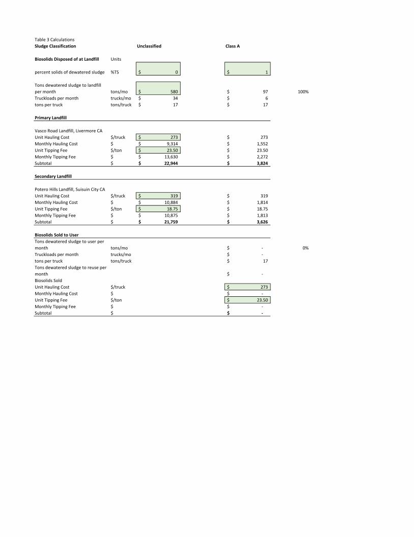
Table 3 CalculationsSludge Classification Unclassified Class A
Biosolids Disposed of at Landfill Units
percent solids of dewatered sludge %TS 0$ 1$
Tons dewatered sludge to landfill per month tons/mo 580$ 97$ 100%Truckloads per month trucks/mo 34$ 6$ tons per truck tons/truck 17$ 17$
Primary Landfill
Vasco Road Landfill, Livermore CAUnit Hauling Cost $/truck 273$ 273$ Monthly Hauling Cost $ 9,314$ 1,552$ Unit Tipping Fee $/ton 23.50$ 23.50$ Monthly Tipping Fee $ 13,630$ 2,272$ Subtotal $ 22,944$ 3,824$
Secondary Landfill
Potero Hills Landfill, Suisuin City CAUnit Hauling Cost $/truck 319$ 319$ Monthly Hauling Cost $ 10,884$ 1,814$ Unit Tipping Fee $/ton 18.75$ 18.75$ Monthly Tipping Fee $ 10,875$ 1,813$ Subtotal $ 21,759$ 3,626$
Biosolids Sold to UserTons dewatered sludge to user per month tons/mo -$ 0%Truckloads per month trucks/mo -$ tons per truck tons/truck 17$ Tons dewatered sludge to reuse per month -$ Biosolids SoldUnit Hauling Cost $/truck 273$ Monthly Hauling Cost $ -$ Unit Tipping Fee $/ton 23.50$ Monthly Tipping Fee $ -$ Subtotal $ -$
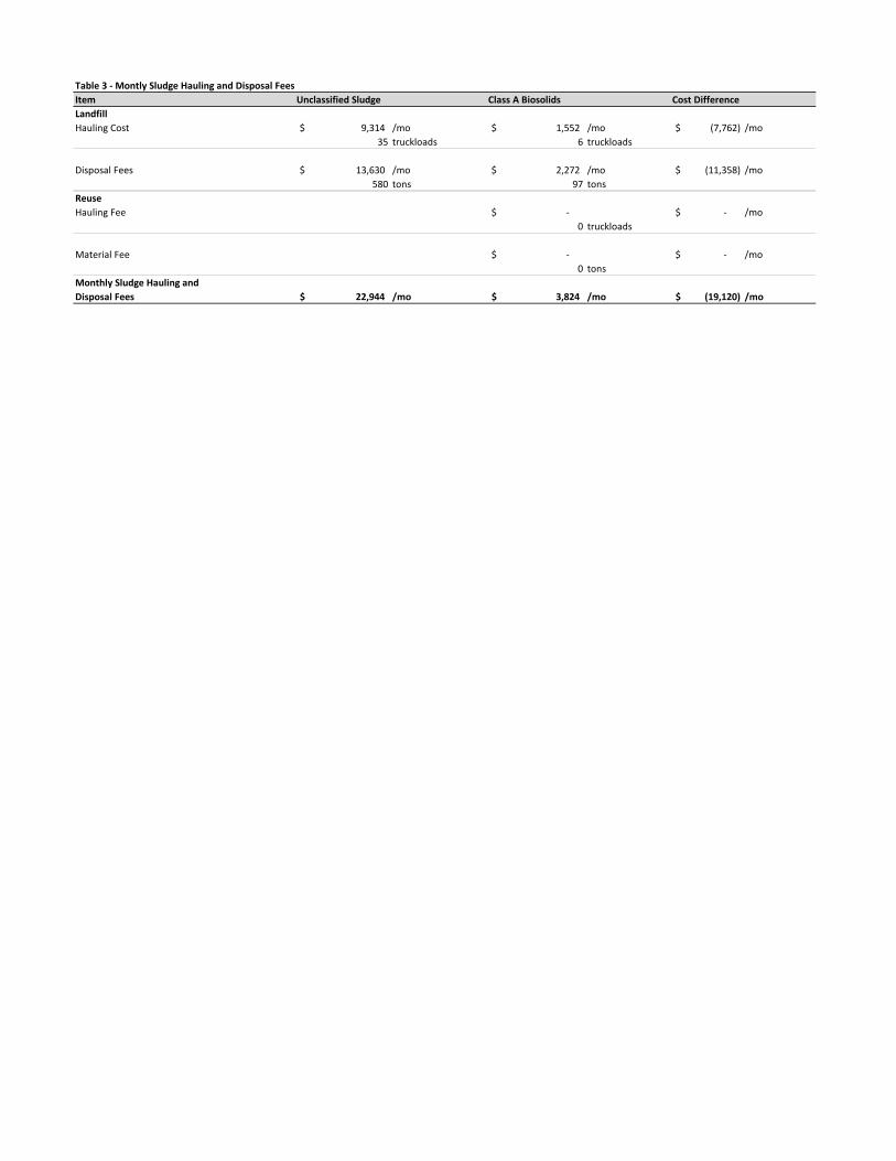
Table 3 - Montly Sludge Hauling and Disposal FeesItem Unclassified Sludge Class A Biosolids Cost DifferenceLandfillHauling Cost 9,314$ /mo 1,552$ /mo (7,762)$ /mo
35 truckloads 6 truckloads
Disposal Fees 13,630$ /mo 2,272$ /mo (11,358)$ /mo580 tons 97 tons
ReuseHauling Fee -$ -$ /mo
0 truckloads
Material Fee -$ -$ /mo0 tons
Monthly Sludge Hauling and Disposal Fees 22,944$ /mo 3,824$ /mo (19,120)$ /mo

Table 4 CalculationsSludge Dryer Therma-Flite Andritz
Hours of Operation% Solids In 15% 15%% Water In 85% 85%%Solids Out 90% 92%%Solids Out 15% 15%%Water Out 1.67% 1.30%%Evap 83.3% 83.7%Tons of dewatered sludge per month 580 tons/mo 580 tons/moInput Dry Solids 87 tons/mo 87 tons/mo
20.1 tons/wk 20.1 tons/wkWet solids input feed rate 6400 lbs/hr 3889 lbs/hrDry solids output feed rate 960 lbs/hr 583 lbs/hr
Hours of operation per week 42 hrs/wk 69 hrs/wk
Hours of operation per month 181 hrs/mo 298 hrs/mohours of operation per day, maximum 24 hr/d 24 hr/d 24 hr/drun days per week Continuous Run d/wk Continuous Ru d/wknumber of starts per week 1 starts/wk 1 starts/wk
warm up time, use gas & elec. 1 hrs/start 1 hrs/startcool down time, use elec, no gas 1 hr/stop 1 hr/stop
total warm up time per week 1 hrs/wk 1 hrs/wktotal cool down per week 1 hrs/wk 1 hrs/wk
Natural Gas (Method 1: w/o warm up and cool down hours)Local Fuel 6.00$ $/MMBtu 6.00$ $/MMBtu
Thermal Energy per lbs water evaporation 1200
Btu/lb water evap 1400 Btu/lb water evap
Thermal Efficiency 0.90 1.00
Fuel Energy per lbs water evaporation 1,326
Btu/lb water evap 1,400 Btu/lb water evap
Water evaporated per month 966,667 lbs/mo 970,870 lbs/moFuel required per wet ton dried 2,210,000 Btu's/ton 2,343,478 Btu's/tonFuel per month 1,282 MMBtu's/mo 1,359 MMBtu's/moMonthly Fuel Cost 7,691$ $/mo 8,155$ $/mo
Natural Gas (Method 2: w/ warm up and cool down)Cost of Natural Gas 43$ $/hr 27$ $/hrWeekly dryer run hours using Natural Gas 43 hr/wk 70 hr/wkMonthly dryer run hours using Natural Gas 186 hr/mo 303 hr/moWeekly Natural Gas Cost 1,831$ $/wk 1,909$ $/wkMonthly Natural Gas Cost 7,934$ $/mo 8,274$ $/mo
ElectricityCost of Electricity 0.14 $/kw/hr 0.14 $/kw/hrTotal Equipment HP Output 110 Hp 75 HpVoltage 460 460Amps 138 96KVA 63.5 KVA 44.2 KVAkW 57.1 kW 39.7 kW Efficiency 1.00 1.00Calculated hourly electrical use rate 57.1 kW 39.7 kW USE hourly electrical use rate from Quote 57.0 kW 56.0 kW Cost per hour 7.98$ $/hr 7.84$ $/hrWeekly dryer run hours using Electricity 44 hr/wk 71 hr/wkMonthly dryer run hours using Electricity 190 hr/mo 307 hr/moWeekly Electricity Cost 350$ $/wk 555$ $/wkMonthly Electricity Cost 1,516$ $/mo 2,406$ $/mo
Miscelaneous ElectricityCoeff. 0.9 Cost of Electricity 0.14$ $/kW h
NEC table
Qty. duty pumps
Description hp Voltage Amps kVA kW min/day hr/mo kW h/mo$/mo each $/moOdor Control Blower 20 460 27 12.4 11.2 1460 730 8160 1,142.39$ 1 1,142.39$ HVAC 10 460 14 6.4 5.8 1460 730 4231 592.35$ 0 -$ Sludge Conveyors 2 460 3.4 1.6 1.4 380 190 267 37.43$ 4 149.70$ Sludge Pumps 3 460 4.8 2.2 2.0 380 190 377 52.84$ 1 52.84$
0.0 0.0 0 0 0 -$ 0 -$ 0.0 0.0 0 0 0 -$ 0 -$
Total 1,344.93$

Table 4 - Monthly Energy CostItem Therma-Flite AndritzNatural Gas 7,934$ /mo 8,274$ /mo(@$6.00 per Million Btu)
Electricity 1,516$ /mo 2,406$ /mo(@$0.14 per kW/hr)
Electricity 1,300$ /mo 1,300$ /mo(miscellaneous)
Monthly Energy Cost 10,749$ /mo 11,980$ /mo
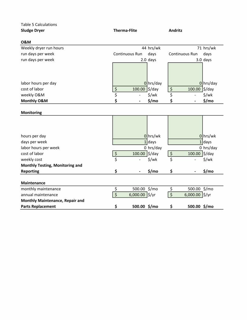
Table 5 CalculationsSludge Dryer Therma-Flite Andritz
O&MWeekly dryer run hours 44 hrs/wk 71 hrs/wkrun days per week Continuous Run days Continuous Run daysrun days per week 2.0 days 3.0 days
labor hours per day 0 hrs/day 0 hrs/daycost of labor 100.00$ $/day 100.00$ $/dayweekly O&M -$ $/wk -$ $/wkMonthly O&M -$ $/mo -$ $/mo
Monitoring
hours per day 0 hrs/wk 0 hrs/wkdays per week 1 days 1 dayslabor hours per week 0 hrs/day 0 hrs/daycost of labor 100.00$ $/day 100.00$ $/dayweekly cost -$ $/wk -$ $/wkMonthly Testing, Monitoring and Reporting -$ $/mo -$ $/mo
Maintenancemonthly maintenance 500.00$ $/mo 500.00$ $/moannual maintenance 6,000.00$ $/yr 6,000.00$ $/yrMonthly Maintenance, Repair and Parts Replacement 500.00$ $/mo 500.00$ $/mo
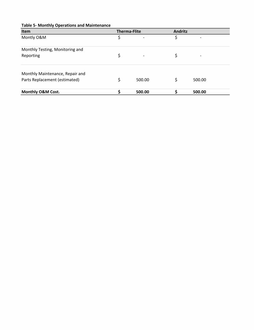
Table 5- Monthly Operations and MaintenanceItem Therma-Flite AndritzMontly O&M -$ -$
Monthly Testing, Monitoring and Reporting -$ -$
Monthly Maintenance, Repair and Parts Replacement (estimated) 500.00$ 500.00$
Monthly O&M Cost. 500.00$ 500.00$

Table 6 CalculationsSludge Dryer Therma-Flite Andritz
Method 1: Construction CostEquipment Cost 2,142,172 1,679,100 ratio of construction to equipment cost 100% 100%Construction Cost 2,142,172 1,679,100 Ratio of design to total equipment & construction cost 10% 10%Design Cost 428,434 335,820 Capital Improvement Cost 4,712,778 3,694,020
Method 2: Response to CommentsSludge Dryer 2,142,172$ 1,679,100$
EquipmentAncillary Equipment 50,000$ 100,000$ Conveyors/Hoppers 100,000$ 100,000$ Total Equipment 150,000$ 200,000$
Buildingwidth 40 ft 40 ftlegnth 90 ft 90 ftlevels 2 each 2 eachtotal area 7,200 sqft 7,200 sqftunit cost 100 $/sqft. 100 $/sqft.steel building 720,000$ cost 720,000$ costconcrete slab thickness 1 ft 1 ftvolume slab 133 cuyd 133 cuydunit cost reinforced concrete slab 500 $/cuyd 500 $/cuydconcrete slab cost 66,667$ cost 66,667$ costTotal Building 786,667$ 786,667$
Site and Elecmob/demob 40,000$ 40,000$ equipment installation and piping 250,000$ 250,000$ electrical, controls, SCADA 200,000$ 200,000$ testing & startup 20,000$ 20,000$ Total Site & Elec 510,000$ 510,000$
Total Construction 1,446,667$ 1,496,667$
Design, field investigation, permittingpercentage of construction cost 15% 15%Total Design 217,000$ 224,500$
Contengency
Percent of Construction and Design 30% 30%Contengency 499,100$ 516,350$
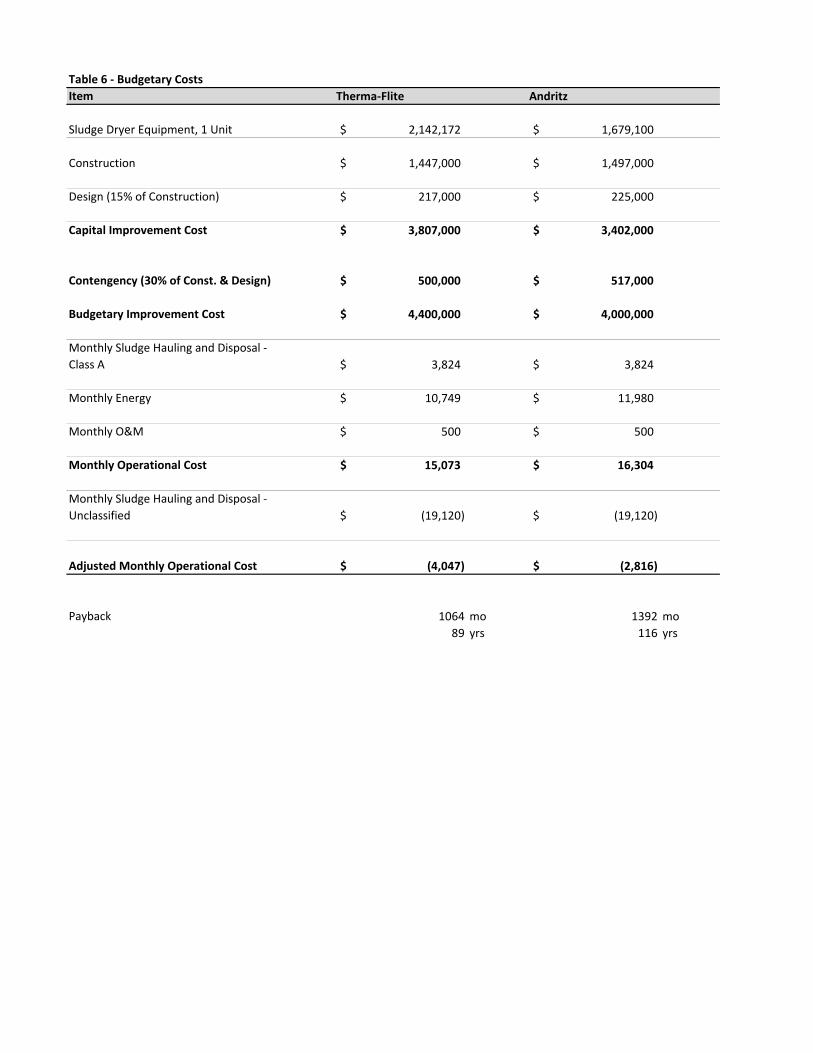
Table 6 - Budgetary CostsItem Therma-Flite Andritz
Sludge Dryer Equipment, 1 Unit 2,142,172$ 1,679,100$
Construction 1,447,000$ 1,497,000$
Design (15% of Construction) 217,000$ 225,000$
Capital Improvement Cost 3,807,000$ 3,402,000$
Contengency (30% of Const. & Design) 500,000$ 517,000$
Budgetary Improvement Cost 4,400,000$ 4,000,000$
Monthly Sludge Hauling and Disposal - Class A 3,824$ 3,824$
Monthly Energy 10,749$ 11,980$
Monthly O&M 500$ 500$
Monthly Operational Cost 15,073$ 16,304$
Monthly Sludge Hauling and Disposal - Unclassified (19,120)$ (19,120)$
Adjusted Monthly Operational Cost (4,047)$ (2,816)$
Payback 1064 mo 1392 mo89 yrs 116 yrs