Embed Size (px)
Citation preview

C_
LO
I
A
ZI---
<
<z
NASA TN D-1552
TECHNICAL
D-1552
NOTE
A STUDY OF A PILOT'S ABILITY TO CONTROL DURING
SIMULATED STABILITY AUGMENTATION
SYSTEM FAILURES
By Melvin Sadoff
Ames Research Center
Moffett Field, Calif.
NATIONAL AERONAUTICS
WASHINGTON
AND SPACE ADMINISTRATION
November 1962
https://ntrs.nasa.gov/search.jsp?R=19630000307 2020-06-28T07:39:52+00:00Z


NATIONAL AERONAUTICS AND SPACE ADMINISTRATION
TECHNICAL NOTE D-1552
A STUDY OF A PILOT'S ABILITY TO CONTROL DURING
SIMULATED STABILITY AUGMENTATION
SYSTEM FAILURES
By Melvin Sadoff
SUMMARY
The results presented show the effects of failure of a stability
augmentation system on the pilot's ability to control while engaged in
a simple tracking task. The results of failures simulated in a fixed-
and moving-cab centrifuge suggest that moving cockpit flight simulators
provide a more realistic evaluation of the transient effects of stability
augmenter failures. In the present study, simulator motions generally
interfered with the ability of the pilots to adapt to the failures. A
pencil-type side-arm controller proved easier to use than a conventional
center stick in coping with pitch damper failures at the higher short-
period frequencies. The use of simple pilot models in the analysis and
prediction of the transient effects of stability augmenter failures
provided encouraging results.
INTRODUCTION
Considerable effort has been devoted in recent years to establishing
basic handling qualities requirements for high-performance aircraft
through the use of piloted flight simulators and variable-stability air-
planes (e.g., refs. i to 6). The results provided by these studies delin-
eate regions of satisfactory, acceptable, and unacceptable vehicle dynam-
ics. It has been considered that the aircraft should be designed so that
when the stability augmentation system is inoperative or has failed, the
vehicle dynamics should be rated marginally acceptable by pilots. Pilot-
rating boundaries have been established only for time-invariant vehicle
dynamics; that is, no attempt was made to determine whether these bounda-
ries apply for sudden stability augmenter failures. Though the pilot is
a remarkably adaptive controller who can, given sufficient time, vary his
own dynamics to maintain constant pilot-vehicle performance over a wide
range of vehicle dynamics (refs. i and 7), little is known about his
ability to cope with the abrupt changes in aircraft dynamics that would
occur during sudden failure of the stability augmentation system (SAS).
(The ability of a human to adapt to more gradual changes in vehicle
dynamics, type of display, etc., is discussed in ref. 8.)

To provide someinformation on a pilot's ability to control a vehicleduring suddenSASfailures of the longitudinal control system, a fixed-and moving-cab simulator study was conducted by AmesResearch Center onthe humancentrifuge at the Aviation Medical Acceleration Laboratory(AMAL), Naval Air DevelopmentCenter, Johnsville, Pennsylvania. In thispreliminary study, the SASfailures were simulated simply by varying thevehicle dynamics_ suddenly; no attempt wasmadeto simulate "hard-over"failures.
The main objectives of this paper are: (a) to illustrate by meansof vehicle response time histories and pilot-vehicle performance measuresthe general pattern and nature of the control problem whenthe pitch SASfails, (b) to assess the effects of kinesthetic and vestibular motion cuesby a comparison of results from tests in fixed-cab and moving-cab simu-lators, (c) to comparethe pilot's ability to control with center-stickand side-arm controllers, (d) to apply simplified pilot transfer-functionmodels to the interpretation and prediction of control problems resultingfrom SASmalfunction.
SYMBOLS
AR
Co
CI
Fs
g
Kp
S
t
T
T2
TL
vehicle normal acceleration factor (ratio of accelerating force to
weight), g
amplitude ratio
numerator constant in pitch transfer function, 1/sec 3
numerator constant in pitch transfer function, 1/sec 2
pilot stick force, lb
acceleration of gravity, lg = 32.2 ft/sec 2
pilot or pilot model static gain, 8s/_, deg/deg or Fs/_ _ lb/deg,
as indicated
Laplace transform variable
timej sec
transition time required for pilot to adapt to c_anged vehicle
dynamics, sec
divergence time to double amplitude, sec
pilot model first-order lead, sec

Yc
8s
A
6
_e
0
Oi
_2ff
'r
q_
wn
vehicle pitch transfer functions
pilot or pilot-model transfer function
stabilizer deflection, deg
incremental change in value over an appropriate time interval
tracking error, deg
mean square tracking error, deg2
vehicle short-period damping ratio in pitch
vehicle pitch attitude, deg
target motion, deg
mean square target motion_ deg2
pilot or pilot-model visual reaction time, sec
phase angle, deg
angular frequency, radians/sec
vehicle undamped short-period natural frequency in pitch,
radians/sec
SIMULATION
In this study the human centrifuge at the AMAL, Naval Air Development
Center, Johnsville was used to assess the effects of normal acceleration
and pitching acceleration on the pilot's ability to adapt to sudden SAS
failures. A detailed description of the simulation setup is provided in
reference i. As noted in this reference, the centrifuge has disorienting
effects on the pilot at normal accelerations below 3g_ therefore, the
moving-cab portion of the study was conducted at a bias normal accelera-
tion level of 3g so that normal-acceleration perturbations were referred
to 3g rather than Ig. The coordinate conversion system used in this study
is the one described in reference I. The purpose of the coordinate trans-
formation analog was to transform the computed linear-acceleration signals
into appropriate centrifuge responses which reproduced the desired normal-
acceleration perturbations accurately, introducing a minimum of spurious
motions. As indicated in reference I, the system used was the best of 16
modes evaluated, and it resulted in centrifuge responses which were con-
sidered fairly realistic by the pilots over most of the range of aircraft

4
short-period dynamics studied. However, at the highest short-period
frequencies tested (_n = 6) and at low damping levels, the introduction
of spurious fore and aft and lateral accelerations had an adverse effect
on the pilots' ability to control.
TESTS AND PROCEDURE
The test conditions for the present study are illustrated in
figure i. The five cases covered in the program are shown in relation to
steady-state pilot-opinion boundaries for short-period longitudinal hand-
ling qualities provided in reference i. The pilot rating schedule for
the steady-state boundaries is presented in table I. Three of the five
cases involved sudden reductions in pitch damping (A,B,C in fig. I); the
other two involved sudden reductions in static stability (D and E, fig. i).
In case D, the static stability rating was changed from 3-1/2 to about
6-1/2 for steady state; in case E, the steady-state rating was unchangedbetween initial and final levels. The failures illustrated in figure i
were simulated simply by step changes in vehicle dynamics between the
initial and final levels. Since SAS failures are probably most critical
when the pilot is required to control precisely, the failures were initi-
ated while the pilot was engaged in a simple pitch-attitude tracking task.
The task input ei was the sum of four sine waves with frequency and
amplitude characteristics as indicated in the table below.
Sine wave component
i
2
34
FrequeBcy,radians/sec
0._77.741
1.2_1
1.80
Mean-square amplitude,arbitrary units
1.0
.5
.15
.07
(For further description of the task, see ref. 9.) Pilot performancewas determined from the ratio of mean-square tracking error _a to the
mean-square target motion _2. This was determined from the incremental
changes in fe2 dt and fei 2 dt over the same time period, so that
-- dtlm ei2 dt
Most of the tests were conducted with a force-command center stick;
however, a brief re-evaluation of damper failures at the higher short-
period frequencies (cases A and B) was made with a pencil-type side-arm
controller with appropriate am restraint (see ref. i).
The test conditions described were evaluated by four experienced
test pilots, including two from the NASA and one each from the Naval and

5
Air Force Flight Test Centers. The majority of the conditions were
evaluated only by two pilots, pilots B and E of reference i. The same
two pilots were used in the present study and are identified as pilots
A and B, respectively.
RESULTS AND DISCUSSION
General Pattern of Control Problem
The general pattern of the control problem encountered during sudden
failure of the stability augmentation system is indicated in figure 2. A
typical time history of the simulated aircraft response characteristics
associated with a pitch-damper failure for case A with the centrifuge cab
moving is shown in figure 2(a). Figure 2(b) presents the associated
tracking-task input and the tracking error, expressed as fei a dt and
f_a dt, respectively. The time at which the pitch damper failed iseasily recognized by the point in time where the aircraft responses
build up rapidly (fig. 2(a)) and where the integral of the error squared
increases abruptly (fig. 2(b)). As shown by these typical results, the
pilot-aircraft combination tends to become unstable immediately follow-
ing the damper failure; this tendency will be discussed in a later section.
The results in figure 2(b) also show that a well-defined transition time
is required for the pilot to adapt to the failure in terms of the time
required to stabilize tracking performance. The more rapid increase in
_c 2 dt relative to the increase in _ei a dt indicated the pilot wouldhave improved the situation by releasing the control.
A control problem, somewhat analogous to that described here, was
indicated by analysis of some of the results of reference 8. Results
of the analysis, considered pertinent to those of the present study, are
provided in appendix A.
Effects of Simulator Motions
The effects of centrifuge flight simulator motions on the pilot's
ability to cope with pitch damper and SAS failures are illustrated by
the comparison of fixed-cab and moving-cab centrifuge results presented
in figures 3 to 7- Shown are plots of pilot performance expressed as
the ratio of mean-square error _ to mean-square input _a.
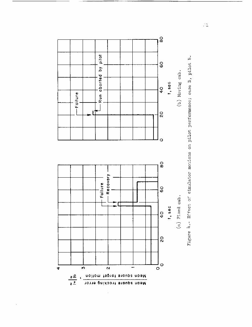
The results in figures 3, 4, 5, and 6 for cases A, B, C, and D,
respectively, show a significant adverse effect of simulator motions on
the pilot's ability to adapt to the failures. This is generally

apparent both from the larger mean-square error during transition andfrom the longer transition times for the moving-cab results. Case C(fig. 5(b)) is of interest because of a nontypical double rise in track-ing error - one at failure and one after the pilot had presumably adaptedto the failure. This result may reflect the difficult adaptation requiredof the pilot after SASfailure for this case. Appendix B describes thetime-invariant pilot adaptation (gain and lead) required for all failuresconsidered and points out that pilot adaptation to a case C failureinvolved a simultaneous reduction in pilot static gain and an increase inpilot lead. Presumably, this adaptation was more difficult to attain bypilot B with the centrifuge cab moving. Results for pilot A in the movingcab (not shown) did not indicate the double rise in tracking error.
In figure 7, which presents results for failure of a static-stabilityaugmenter (case E), a reverse trend is noted; that is, effects of motionfeedback to the pilot were beneficial. In this case, the centrifugemotion mayprovide the pilot with additional lead information I requiredfor stabilizing a lightly dampedvehicle with zero static stability. (Seeref. 7.) It should be noted, however, that in other cases which demandedrelatively large lead of the pilot (e.g., cases C and D, figs. 5 and 6),an adverse effect of motion was observed. As noted in appendix B, theselatter two cases required a simultaneous large reduction in static gainand an increase in lead which mayhave been more difficult to achieve withthe centrifuge cab moving.
The effects of simulator motions on the transition times and trackingperformance are summarizedin figures 8 and 9. In general, it can be con-cluded that simulator motions had an adverse effect on both measures; thatis, longer adaptation times were required, and the performance duringtransition was poorer.
These results suggest that simulator motions are generally requiredfor a realistic assessment of a pilot's ability to cope with stabilityaugmentation system failures. It should be noted that someof the compari-sons of fixed-cab and moving-cab results presented maybe contaminated bythe spurious motions associated with simulation of aircraft motions on anylimited degree-of-freedom simulator. In the present study, spuriousmotions were apparent to the pilots, particularly at the highest short-period frequencies (see section on simulation and ref. 1). Consequently,the adverse effects of motion, measuredwith the centrifuge, maybeexaggerated3 particularly for case A.
ILead information is the tracking-error rate information used by thepilot to maintain closed-loop stability. Results in reference 7 indicatethe pilot develops large lead terms in order to control the pitch attitudeof a lightly dampedvehicle with low static stability.

Comparisonof Center-Stick and Side-Arm Controller Results
A brief study wasmadeto determine whether a pencil-type side-armcontroller could reduce the adverse effects of simulator motions on thepilot's ability to adapt to damperfailures. Center-stick and pencilcontroller tracking results with the centrifuge cab in motion are pre-sented in figures i0 and ll. The results in figure I0 for case A showthat the side-arm controller markedly improved the pilot's ability tocope with a pitch-damper failure at high short-perlod frequencies. Thepilot appeared to adapt to the failure almost immediately with noapparent pilot-vehicle instability; whereas, with the center stick, hisperformance deteriorated markedly during the transition period of about15 seconds. (In one instance (fig. ll(a)) the pilot lost control andaborted the run.) With the pencil controller the deterioriation ofperformance for case B was relatively small; however, the transitionperiod was somewhatlonger than that observed for the center stick.
These results indicate that the adverse effects of centrifuge motionfeedback on the pilot's ability to adapt to pitch-damper failures can bereduced by the use of a side-arm controller, particularly when the fail-ures occur at high short-period natural frequencies. As observed in thepreceding section, spurious centrifuge motions, particularly fore and aftaccelerations, probably interfered with the pilot's ability to adapt todamperfailures at high frequencies with the conventional center stick.The improvement shownfor the side-arm controller under these conditionsis probably attributable to two factors: the arm restraint used helpedminimize inadvertent control inputs, and the lowmass and inertia of theaide-arm controller device, which was operable with the fingers, permittedsmoother, more precise control inputs than those possible with the centerstick.
Analysis Using Simplified Pilot Models
The transient effects of failure of a stability augmenter havebeen discussed with reference to the general pattern of the controlproblem, the effect of motion feedback to the pilot, and the effect ofcontroller design. It is obvious that we have been discussing a closed-loop control problem; that is, the characteristics of the pilot responsecoupled with those of the vehicle response result in a marked transientdeterioration of closed-loop performance. Methods for analyzing theperformance of closed-loop systems are widely used in automatic controldesign. The results of extending these methods to systems with the pilotin the loop have been encouraging (refs. i, I0, ii). Weshall describethe application of these techniques, using simplified pilot models,to predict pilot-aircraft instability immediately following pitch-damper

failures. The cases selected for analysis illustrate the extremeconsequencesof suddendamperfailure.
Exa_le cases.- Results in the preceding sections have indicated,
in general, a tendency for the pilot-aircraft system to become unstable
(divergent) in varying degree during the transition period following
failure of the stability augmentation system. In several instances the
instability progressed to the point where the pilot lost control of the
vehicle. Two such cases that occurred following pitch-damper failure
at high short-period frequencies are shown in figures 12 and 13. Fig-
ure 12(a) presents results for a case B (fig. i) pitch-damper failure
with the centrifuge cab moving. In this case, the failure was totally
unexpected by the pilot; the failure was first encountered in a moving
cab, whereas the normal test procedure was to investigate the failure
first in a fixed cab. The aircraft responses following failure
(fig. 12(a)) show a divergence time to double amplitude of roughly i
second. As the normal acceleration reached about 5g, the pilot aborted
the run.
In figure 13, data are shown for a case documented in flight in
which control was completely lost. In this case, the pilot was flying
at low altitude at high speed. There was evidence that the pitch damper
failed just prior to the time for which data are shown. Here, again,
the divergence time to double amplitude of the aircraft response was
roughly i second. Since the damping of the unaugmented vehicle provided
good response with controls fixed (time to one-half amplitude of about
0.2 sec), the pilot must have introduced large negative damping moments.
The precise altitude control task of the pilot at the time the pitch-
damper failed would, as noted earlier, tend to exaggerate the effects of
the failure.
The results in figures 12 and 13 indicate that the limits of
acceptable vehicle dynamics should be carefully selected to insure that
the vehicle will be controllable within these limits if the stability
augmentation system should fail. Evaluations obtained from tests with
time-invariant vehicle dynamics should be checked by tests similar to
those described here.
Pilot models.- Methods for analyzing the stability of closed-loop
systems are widely used in control design and have recently been applied
to pilot-airframe stability studies by appropriate assumptions of the
pilot model or transfer function (see refs. i, i0, and ii). In this
section, a description is given of the application of these techniques
to predict pilot-aircraft stability during the initial stages following
pitch-damper failures.
The analysis procedure used was to determine the pilot model
required to operate a vehicle with good dynamics (prior to damper
failure) and to assume, conservatively, that this model would be initially

9
unchanged following damper failure. The resulting closed-loop stability
characteristics chould then be compared to those actually experienced.
Data are analyzed for the cases in which the pilots lost control of the
vehicle following failure of a pitch damper (figs. 12 and 13). The
method described in reference I was used to deduce the required pilot
dynamics. This procedure can be described briefly by means of figure 14
which shows in block-diagram form the closed-loop pilot-aircraft system
considered. As indicated, the target motion or forcing function is repre-
sented by el; c is the tracking error; Yp, Yc are the pilot and vehicle
transfer functions; as is the control surface deflection; and @ is the
aircraft pitch response. The airplane transfer-function coefficients Co,
Cl, 2_n, and _n 2 were adjusted to appropriate values, and the pilot
model gain Kp and lead TL were adjusted to values which resulted in amatching of the actual closed-loop performance with minimum introduction
of lead. Since closed-loop performance data prior to the damper failure
in flight (fig. 13) were not available, the lead term was assumed zero and
the gain was adjusted to optimize closed-loop performance. The vehicle
dynamics - in the present case the damping term 2_n - were then changed
to correspond to those with damper inoperative, and the resulting closed-
loop stability was assessed.
Correlation of results.- Results of the analysis of the data in
figures 12 and 13 by means of this simplified approach are presented in
figure I_. Shown in figure 15(a) is the correlation of the predicted
results and the actual results expressed in terms of the decrement in
damping due to the destabilizing influence of the pilot. (The damping
decrement A 2_n is simply the difference between the unaugmented air-
plane damping and the closed-loop damping of the pilot-airframe system
for an unadapted pilot model as described above.) The correlation based
on the closed-loop stability, expressed in terms of divergence times to
double amplitude T2, is given in figure 15(b). Fairly good correlation
of the results is shown. In addition to the analysis of the examples
shown in figures 12(a) and figure 13, a run, labeled in figure i2(b) as
a repeat run, was also analyzed. In this run, which followed immediately
that shown in figure 12(a), the pilot was not informed whether the damper
would fail again. Exan_nation of the tracking performance data for this
run, however, indicated the pilot tracked less energetically during the
initial phase of the run in anticipation of a possible failure. This
caution in tracking performance prior to failure (relative to the first
run) corresponded to a reduction in pilot model gain of about 50 percent;
consequently, milder transition characteristics were predicted for this
case. (See fig. 15.) It should be noted that, if actual performance
data had not been available for this run, the predicted results based on
optimum performance would have been about the same as those shown in
figure 15 for the initial run. These results demonstrate the need, in
assessing the effects of SAS failures, for considering the type of task
in which the pilot is engaged, and, hence, the tightness of control or
gain he is initially using.

lO
In view of these encouraging preliminary results, it maybedesirable to check the damperauthority and unaugmenteddamping for agiven vehicle design by the procedure described to insure at least
neutral closed-loop stability in the event of damper failure.
Neutral pilot-airframe stability will be assured, for example, if
the unaugmented airplane damping is at least equal to the damping decre-
ment produced by the destabilizing effect of an unadapted pilot model
(see fig. 15(a)). The pilot models for the augmented vehicle may be
determined as outlined above, or established by means of pilot-vehicle
system surveys similar to those described in references lO and ll.
It is emphasized that these results apply only to the initial part
of transition and that the cases analyzed were selected because they
reflected the extreme consequences of the type of SAS failures considered
in this study. In these cases, the elements of complete surprise and the
effects of motion feedback combined to interfere seriously with the
pilot's ability to adapt to the failures. Considerable work remains to
be done to define the precise mechanism by which a pilot adapts to SAS
failures of various kinds and to determine the effects of realistic
motion cues on pilot adaptation.
CONCLUDING REMARKS
The results of a brief simulator study to determine the transient
effects of failure of the stability augmentation system on high-
performance aircraft have been presented and discussed. The failures
were initiated while the pilot was occupied with a pitch attitude track-
ing task, since the consequences of SAS failure were anticipated to be
more serious when the pilot was required to control the vehicle attitude,
altitude, or flight path precisely.
The results indicated, in general, a well-defined transition time
required for the pilot to adapt to SAS failure. The transition was
characterized by a marked increase in tracking errors (to levels gener-
ally higher than those observed following adaptation), and its length
depended on the type of failure and whether the simulator was fixed or
moving. Comparative fixed-cab and moving-cab centrifuge simulation of
stability augmentation system failures indicated that simulator motions
generally had an adverse effect on the pilot's ability to cope with the
failures; in one case, however, the pilot had less difficulty adapting
to the failure in the moving-cab simulation. These results suggest that
moving-cockpit flight simulators should be used for a realistic assess-
ment of the transient effects of stability augmenter failures. Compara-
tive results showed that the pencil controller was more effective than
the center stick in alleviations of some of the adverse effects of
simulator motions on pilot's ability to adapt to SAS failures.

ll
The use of simplified pilot models or transfer functions inanalyzing and predicting extreme effects of damperfailures on pilot con-trol of a vehicle provided encouraging results, since the magnitude ofthe destabilizing influence of the pilot or the degree of closed-loopstability correlated fairly well with the actual results. Considerablework remains to be done to define the precise mechanismof pilot adap-tation to rapid changes in control task and to determine the effect ofrealistic motion cues on pilot adaptation.
AmesResearch CenterNational Aeronautics and SpaceAdministration
Moffett Field, Calif., Aug. 20_ 1962

12
APPENDIXA
TIME-VARIABLE_ DYNAMICS
In this section, someof the results of reference 8 are recast in asomewhatdifferent form to relate them to results in the present paper.The study conducted in reference 8 is also considered pertinent to thepresent investigation because it represents an initial and interestingeffort to determine directly the time-variable adaptive behavior ofhumancontrollers. The experiment consisted of measuring changes in theclosed-loop, human-operator dynamics associated with changes in display,process, or "vehicle" dynamics_ etc. The experiments were performed witha tracking task similar to that used in the present study. The subjectsat in front of a cathode-ray oscilloscope on which was displayed eithertask input and vehicle response (pursuit display), or only the error(compensatory display). The subject was instructed to manipulate a smallcontroller to minimize the error.
Results are presented in reference 8 showing the changes in closed-loop humandynamics (average of eight subjects) that occurred as thevehicle dynamics were changedfrom unit gain (Yc = i) to pure integration(Yc = 1.61/s) and vice versa for both compensatoryand pursuit displays.The change in vehicle dynamicswas generally completed within 6 secondsof the start of the change. Analysis of the average closed-loop operatordynamics Yp/I+YpYc during the change in vehicle dynamics from unit gainto pure integration with a compensatorydisplay revealed somewhatthesamepattern of adaptation to SASfailures observed in the present study.Specifically, time histories of average tracking error (fig. 16) deducedfrom the results given in reference 8 are fairly similar to the resultsobtained in the present study (e.g., fig. 2(b)). It was necessary todetermine the error indirectly from the over-all system transfer functionYpYc/l+YpYc, since the total tracking-error results are not provided inreference 8. The time-variable results (60 to 120 seconds, fig. 16) areshowndotted because they are determined from data which are inherentlyless precise than the time-invariant results (see ref. 8). The deducedtracking error (fig. 16) shows that adaptation occurred within about 15to 30 seconds of the start of the change in dynamics. As indicated infigure 16, the mean-squarederror increased about five-fold as the vehi-cle dynamics changed from unit gain to pure integration. The associatedopen-loop humantransfer function (fig. 17) indicate that the subjectsreduced both gain and phsse lag appreciably as they adapted to the changein vehicle dynamics.

13
APPENDIX B
TIME-INVARIANT PILOT MODEL CHARACTERISTICS
A summary of pilot-model characteristics_ taken from reference i,
is reproduced in figure 18. These results show the time-invariant, pilot
response characteristics (determined by the performance-matching technique
described in ref. i) for the wide range of vehicle longitudinal short-
period dynamics covered in the reference I study. Also provided in fig-
ure 18 (dashed lines) are the changes in gain and lead required for the
pilot to adapt to the various simulated SAS failures considered in the
present study. These results show that the damper failures at high short-
period frequencies (cases A and B) required primarily a reduction in gain
Kp. Damper failure at low short-period frequency (case C) required a
simultaneous reduction in gain and a large increase in lead. For the two
cases involving failures of static stability augmenters, a simultaneous
reduction in gain and increase in lead was required for case D, while case
E required primarily an increase in lead.

14
REFERENCES
l•
1
1
_Jr.
.
.
.
•
Sadoff, Melvin, McFadden, Norman M., and Heinle, Donovan R.: A
Study of Longitudinal Control Problems at Low and Negative Damping
and Stability With Emphasis on Effects of Motion Cues. NASA
TN D-348, 1961.
McFadden, Norman M., Vomaske, Richard F., and Heinle, Donovan R.:
Flight Investigation Using Variable-Stability Airplanes of Minimum
Stability Requirements for High-Speed, High-Altitude Vehicles.
NASA TN D-779, 1961.
McNeill, Walter E., and Vomaske, Richard F.: A Flight Investigation
To Determine the Lateral Oscillatory Damping Acceptable for an
Airplane in the Landing Approach. NASAMEMO 12-I0-58A, 1959.
Creer, Brent Y., Stewart, John D., Merrick, Robert B., and Drinkwater,
Fred J., III: A Pilot Opinion Study of Lateral Control Requirements
for Fighter-Type Aircraft. NASA MEMO 1-29-59A, 1959.
Vomaske, Richard F., Sadoff, Melvin, and Drinkwater, Fred J., III:
The Effect of Lateral-Directional Control Coupling on Pilot Control
of an Airplane as Determined in Flight and in a Fixed-Base Flight
Simulator. NASA TN D-If41, 1961.
Creer, Brent Y., Heinle, Donovan R., and Wingrove, Rodney C.: Study
of Stability and Control Characteristics of Atmosphere-Entry Type
Aircraft Through Use of Piloted Flight Simulators. Paper No. 59-129,
Inst. Aero. Sci., 1999.
Hall, lan A.M.: Effects of Controlled Element on the Human Pilot.
WADC Tech. Rep. 57-509, Aug. 1958 .
Sheridan, Thomas B.: Time Variable Dynamics of Human Operator
Systems. AFCRC-TN-60-169, March 1960.
9. Sadoff, Melvin: The Effects of Longitudinal Control-System Dynamics
on Pilot Opinion and Response Characteristics as Determined From
Flight Tests and From Ground Simulator Studies. NASA MEM0 I0-I-58A,
1958.
i0. Ashkenas, Irving L., and McRuer, Duane T.: The Determination of
Lateral Handling Quality Requirements From Airframe-Human Pilot
System Studies. WADC TR 59-135, June 1959•
ii. McRuer, Duane T., Ashkenas, Irving L., and Guerre, C. L.: A Systems
Analysis View of Longitudinal Flying Qualities. WADD TR 60-43,
Jan. 1960.

15
c)
_D
H
O
H
O
E-_
H
i
H
.r-I
o.r__O
(J
o+_
-P .H
,d O
o o
co
A _
00,._1
_3 _ O
,-t O
(D
_ ,o q--t %
-, % r--t
,--t +_ r-t
o o _ o 0o
r--i oj c_ ._- t_ ,..o
ho
o
.r-I4-_
r_
or-t ._
o _
o
o
o
cH_D
O oZl.r_
bD_
4-_ 0 0
O
c1
(1) r_
O _
o
-O -t._ .t_ .O
oz_ooo o o o
oo
c_o-r-I4o
0 c_
(DP_0
h_
-_Ir_
+-_
q-_O
%
.,-t

16

0
c_nc
o
o 0 0I'0 04 --
alqo&s
OaS/ Suo!pDJ '_um f'pSJonbS
0
alqD&sUN
_3usnbeJ-I
(..o
i..,3
ro
oJ
o0
I
I
,q
¢J
°r-I
.q
.r4
0
r-!°r-I
E q-4 0+_
e"-,-- _ +_
+_ ._0 C_r-t
E3 +_ qq
+_
°_
+_
|
r-4
%

STABILIZER -5DEFLECTION, 0
(_s, DEG 5
--4 k"- I 0 SEC
STICK FORCE 25F
Fs, LB 0 E-25
PITCH ANGLE
0, DEG
NORMALACCELERATION
AN, g
-IOL
/,, ADAPTATION COMPLETED
EVALUATION STEPS /tDAMPER FAILED t
i i / i / /1 ] / = "<', 1'
TRACKING STARTED
(t=O)
0 EVALUATION STEPS
PITCHING I0 EVELOCITY, _, 0
DEG/SEC -I0
PITCHING 20 [ACCELERATION 0
_ DEG/SEC 2 -20 L
5<igure _.- Time histories of t,:_icai pitch-damper falluz'e.

N
Q)i,,_
O
--1
O"
¢t)
¢-
O
O
t-
C
O
-6Cr_
Q,)
r
160
140
120
100
80 160
60 140
40 120
20 ,. 100
0- o 80
(.,3
_ 60
-6
c 40
//
/
//
/
//
//
Ada )tationcorn )leted --"
//
//
20 ifJ
I0 20 30
I IDamper failed
1Jl40
t_ sec
(b) Tr,Js,;king per<'ozmailce .
/
J
50
//
J
//
I
J
60
170
Figur_ 2.- Concluded.

@
0
r_
014_
! !>l
)
b
II
br
i
Fi
i
III
U
o._ E -->
_ ZI
r
L-
0
t.L
I Lr---
I
z___. , uo!low ;aBJO_ eJonbs UOel/_
!
D)
- . m
0
L.
0
0
0
0
0Od
0
0_D
0_D
0
00,,.I
00
h
_d
• o_
0 ,-_
.c-I
_3
_a0 •
_-_P_
,o_t 00
© -,©._-,
4_ °_
ul
m c_
(1)m %
© r--t
0
0
4-_
©
I
:I JOJJ_ 5UI_OOJ;, oJonbs uoe_
0co
LL
JQ
_0Q)
J_
c"
rY
.J
0
-_ rYLL
0_o o
0 _ "H
O
%(D
O
-r"lO _
O
O.r-t
co o
O+__3
,-4
o_ •
©
O+_
O n21 O
0 _ N
" _ CH4.. F_I
I
N
o g.r-t
O
z-o uol_,ouJ $8DJDi 8Jonbs uo8IN
Z_. _ JOJJg _U!HOOJ$ eJonbs uogl_l
00

°w
m 0 =
LI
I,.
QJ
00
rr
0(1) c)
"; t__U-
O
o _4o
.; °r-t
® _0 o"_ ffl .H
O
rQ *,',
oO _
ocHh¢)
o -_,--t.,---t
o
r/l
O.r-I
O _
O+_
,-4
o i
ej4o
0 _ _
c_L_
©0
-H
.D uo!i.ouJ #eDJo,t eJonbs UDelhl
JoJJe {)U!_IODJI e4Dnbs UOOlAI
00

2_
*(30¢D Q)C u_
-_ ur)c_tc)
o_t-
o_"_" O
_-oO
tK)
t.._O
O0CO
h.
0LL
m 4)
0_.
0
0
0
o
0
0
0
0
0
0 _
0C_
0
.r-t
v
0
,d
.r"l
v
..@0
r-_-H
0
c6¢.)
°_@0
0
%
-00
,-t-,--I
0
o.rl4-_0
%0
4o_3
?r/1
o
©
i
©
.r-t
if)
.0
m _
z_•
uo!l.0W _,gbJO# eJonbs uog_
JoJ4g _U!_3DJ_ eJ0nbs UDgV_
OO

OOO
o
I _i
Io
o
oO
,-4P=
B_O
°_
C3mU_
0
0N
0
0CO
0
0
0OJ
u
(.I,
o
_0.H
0
(1)
*H
c_
-po
H-H
E©m_3
O
%o
%©
OH,H
O
O.r-t
4._
.Hul
o
4__o
I
@
,r--I
Ur_
UO!IOUJ _e640_ eJDnbs UDI)_I
J0JJe bu!N0oJl eJDnbs uoa_l
O
O

,m. bJv
aoao o
u
"io c
x o°_u_
O@
Q @
@
IO
I I I I I I I
@ @
0
C Q)Ira.
o o-
_.E-o
L;--"•I I I I I
o o ore) C_l --
I 'aw!_ uo!_!su0J1
iv
i
¢7
Q
_D
0 o0
03
<[
W
- O
0-o o
o
0
v
4o0
,v-(
+_
0
+o
a3
4oo
,q0_
I
.rt
a3
¢.)!
N
_H
©
-rl
%
Or..)
!
c_
.rt

0 0
0
"0 r"
X 0.I
O0
4-
4-
i i i
iv
®
! I I
u') _-
iw
OQ
@
• Q •
I I I I I I
Q •
• Q
I I I I I I
I¢) Od --
IJJ
a
(.3
nn
W
(J
03
0
0..,-4-p
K_p -_
0 h
_ °r-t
%O%%@
"rlN
a3
4_
i
.r-t
c_
O!
x.r--I_ +-_
H _
vO
!
.,-t
u ¢UO!_OUJ _g_JOl gJOnbS UDg_J
.ioJJg5u!_oo_,_ eJonbs UOal_l

00
Lm
FIi3L
OJ _I -- --
0--_0
rr
IJ-
0G0
0
0 m o
.rloc_o
0
0
0
0
0
0oJ
0
_ o
o
I
o
4 .r-I0 ca
o-p
,--t
o
_JP_
+_-rl
CO P0
0 .r-I•_ P_-p
¢) 0
0tO .r--I
b"
°_
_ m
%
•T--t -o %
m ,-I _•rt O
_ .r-t
_3 _3
!
c;
-r-t
z-o UO!_OW _@[:).lD_ eJDnbs UD_I_
JoJJe [_u!_:)oJ_ eJDnbs UDe_

("
_P*e-
. _ --_._ --- --0 cs
"s
.-'_ _ >,
Ia.. n,"I
C
II
>,
00
cc
1.1-
_Z
UO!_OUJ _8DJOl 8Jonbs uog_
II
I
_I
mm._Q
I
IIIII
JOJJe _)U!_OOJ_ gJonbs u0el_l
0co
0LO
U
o4"--
0c_J
0
0CO
0(D
0
0Od
00
_3
(/]
c_I
4 ®r q +_,-_
0 ,-_
+_ 0
0 @
H•_ +_
U] .,._
_a4_
_ m
A t _(3
+'_ 0
0-_
_ -r-t 0
© ©
_ +_
0
!
4r-t
_a0

STABILIZER -5DEFLECTION, 0
8 s , DEG 5
ESTICK FORCE, 0
Fs, LB -25
PITCH ANGLE,e, DEG
NORMAL
ACCELERATION
AN, g
,°E5
0
-5
-I0
2
0
_PILOT TERMINATED RUN DAMPER FAILED
_"I__'_ ":_"-'I,"_""_"-I'''_TRACKING STARTED DAMPER FAILED TRACKING STARTED
ADAPTATION COMPLETED
PITCHING I0
VELOCITY, e, 0
DEG/SEC -I0
PITCHING 20 FACCELERATION 0 /
_: DEG/SEC 2 -20L
\(a) Initial run. (b) Repeat run.
Figure 12.- Moving-simulator evaluation of pilot's ability to cope with
sudden pitch-damper failure; case B (fig. I).

3O
,o-
0
,.i- li)
_>_N
¢/']
4
0
-4
..-" _ _ /
\,, / -\ /\ / 1/
2O
O',_,)
"10
¢-
_ 0.lt.-
n
-I0
J
f
.P-_ ///
16
Z
c:"0
U¢.)
0
EL.
0
Z
12
8
4
0
-40
//
f "x /
/-,,, / \ /\ , \ /
.2 .4 .6 .8 1.0 1.2 1.4 1.6
t, sec
Figure 13.- Example of pilot loss of control in flight.
/
1.8

_±
c_
U>..
c.,O
1:2.3,-
(:l:)
¢_1C:
4-
o o,I0
Z
II
U>..
I-JI
G_
0.
II
>-
bOc_
.r-I
¢J
o,-I
QJ
CQ
q-tc_
C_)
-rl
c_!
-i_O,--I.H
!
,-t
©
b_.r--t

:3
(_
0_
° •0 = =_. m m(.) = =
0 U (J
_ E El..) 0 0_" C C
E'o "o
_g co_ _
o[3<]
\
0
l-
- _) "U
Q)q..,.
_,- re) oJ
\\
C0
.Ira0
m(bk.
- _)-(.3
_"_ .¢)
q,..
_ °
\\
lon&3v(_/)
\\\
\
\
N
m
\o-- O
(x)
3
\O
O
.,I,.,.
°_
4-b
_. ®
v
b.0
>
A
4.)
_b
k"%3
N
,-4
_c_p0
rd
0
h
r-i
P
C)
_d
,d
C)
p_
q_0
0
-p
,-I
0C.)
©
.,-I
.r-t
IonlOV(um_ )

K3
t_c
= _ °
o
0-
L #= _wlw°
I
z-o uo!&otu ;g_Jol eJOnbs u0e_
z _- aoJae 6U!_OD_I _Jonbs uDa_
00
0_D
O O O O O
O K) c_ (13 _I"
O
I'--I
I
0 O
£ .... 00
O
O
O
O
O
O_0
OoJ
s$lun /_JDJJ,!qJo'p;_Jonbs JOJae IDJS_JrUI
O00
O
O
O
_3q)
L)¢)u)
,m,=-
o
h(I}
h_
+_
c_ o0J
o
o
o
,.Q
r.a
%O%h@
4_
H
c_
-o
©rq
,-I
"H
.rt
O %
_._
--_ o-o
_r-'t
r'_ H
q._ -.JO
_ .r't
"_ b.0
0
U_*r'-t
I
©

_;i_.
I00
o°--
o
(1)
34--
IQ.E<{
I0
rl Yp for
Yp =
1.61 [t _
Yc = s ;
f_iii
40 e -°'3s (1+0.25s)
.I
Figure 17.-
I IO
_; radians/sec
(a) Amplitude ratio, _g.
Time-invariant, open-loop transfer functions.

55
O
O
t-Q.
0
-4O
-8O
-120
E _
O
-1600 2 3
oJ, radions/sec
4 6
(b) Phase lag, Yp.
Figure 17.- Concluded.

2O
I0
3.5 5.0
o..
I
\\
.5
.30
0 Operating points before simulated failure
6.5
¢! 4!
, /
.4 .8 1.2 1.6 2.0
T L , sec
2.4
Figure 18.- Summary of time-invariant, pilot-model characteristics,
including adaptive changes required for pilot to cope with the
various simulated stability augmenter failures considered.
NASA-Langley, 1962 A-703