Embed Size (px)
Citation preview

Technical Note - TN 039: 2017
© State of NSW through Transport for NSW 2017 Page 1 of 1
Technical Note - TN 039: 2017
Subject: Withdrawn sections of RailCorp standards due to update of infrastructure lighting requirements
For queries regarding this document [email protected]
www.asa.transport.nsw.gov.au
Issued date: 28 September 2017
Effective date: 28 September 2017
This technical note is issued by the Asset Standards Authority (ASA) to notify that the sections of
the RailCorp documents listed in Table 1 are now withdrawn from use:
Table 1 – Withdrawn sections of RailCorp standards
RailCorp standard Withdrawn section
ESC 520 Level Crossings, version 2.3 Section 5.12
SPG 0724 Level Crossing Protection Equipment – Installation, version 1.4
Section 6.11
The lighting requirements contained in these sections are now superseded by the requirements
specified in T HR SS 80001 ST Infrastructure Lighting.
Authorisation:
Technical content prepared by
Checked and approved by
Interdisciplinary coordination checked by
Authorised for release
Signature
Date
Name Marc Janowski Gary Bayman Jason R Gordon Jagath Peiris
Position Principal Engineer Building Services and Electrical
Lead Stations and Buildings Engineer
Chief Engineer Director Network Standards and Services

Engi
neer
ing
Spec
ifica
tion
LEVEL CROSSING PROTECTION EQUIPMENT - INSTALLATION
SPG 0724
Engineering Specification Signals Construction Specification
Version 1.4
Issued August 2012
Reconfirmed 02 July 2019
Owner: Chief Engineer, Signals & Control Systems
Approved by:
Warwick Allison Chief Engineer Signals & Control Systems
Authorised by:
Paul Szacsvay Principal Engineer Signal Research & Development
Copyright The information in this document is protected by Copyright and no part of this document may be reproduced, altered, stored or transmitted by any person without the prior consent of RailCorp.
RailCorp accepts no liability whatsoever in relation to the use of this document by any party, and RailCorp excludes any liability which arises in any manner by the use of this document.
RailCorp makes no warranties, express or implied, that compliance with the contents of this document shall be sufficient to ensure safe systems or work or operation. It is the document user’s sole responsibility to ensure that the copy of the document it is viewing is the current version of the document as in use by RailCorp.
Disclaimer This document was prepared for use on the RailCorp Network only.
UNCONTROLLED WHEN PRINTED Page 1 of 50

RailCorp Engineering Specification — Signals — Construction Specification Level Crossing Protection Equipment - Installation SPG 0724
© RailCorp Page 2 of 50 Issued August 2012 UNCONTROLLED WHEN PRINTED Version 1.4
Document control
Version Date Summary of change 1.0 Replaced part of SC 07 60 00 00 SP - Level Crossings
Version v.4.1 of 20 October 2006. 1.1 06/05/2008 Reformatted to RailCorp format.
Various changes to all sections 1.2 May 2010 Application of TMA 400 format. 1.3 10/05/2010 Section 5.2(b) – min distance amended to 1500mm. Added
reference to dwg M06-244 Sh 3. Section 5.3.3 – reference to Duragal posts added.
1.4 22 August 2012 Updated document template resulting in some changes to section numbering. Sect 5.7 added list item (e). Section 6.5.1 added list item (f).
Summary of changes from previous version
Summary of change Section Section 5.7 added list item (e). 5.7 Section 6.5.1 added list item (f) 6.5.1

RailCorp Engineering Specification — Signals — Construction Specification Level Crossing Protection Equipment - Installation SPG 0724
© RailCorp Page 3 of 50 Issued August 2012 UNCONTROLLED WHEN PRINTED Version 1.4
Contents
1 Introduction .............................................................................................................................5 2 Scope........................................................................................................................................5 2.1 Purpose.....................................................................................................................................5 2.2 Application.................................................................................................................................6 3 Reference documents.............................................................................................................6 3.1 Australian and International Standards.....................................................................................6 3.2 RailCorp Specifications .............................................................................................................7 3.3 RailCorp Design Drawings........................................................................................................7 4 Terms and definitions.............................................................................................................8 4.1 Operation, Testing and Commissioning of level Crossing protection .......................................9 4.2 Warranty....................................................................................................................................9 4.3 Quality .....................................................................................................................................10 5 Road Crossings.....................................................................................................................10 5.1 General....................................................................................................................................10 5.2 Services...................................................................................................................................10 5.3 RX-5 Assembly - Posts (Masts) ..............................................................................................10 5.4 RX-5 Assembly Mast Installation ............................................................................................11 5.5 RX-5 Assemblies.....................................................................................................................12
5.5.1 Flashing Signal Lanterns .........................................................................................12 5.5.2 Booms and Boom Lights..........................................................................................13 5.5.3 Enlarged Background ..............................................................................................13
5.6 Audible Warning Devices ........................................................................................................13 5.7 Signage ...................................................................................................................................14
5.7.1 Road Authority Signage...........................................................................................14 5.8 RX-5 Assembly Foundations ..................................................................................................15
5.8.1 Posts without Boom.................................................................................................15 5.8.2 Posts with Boom......................................................................................................15
5.9 Road Pavement Markings.......................................................................................................15 5.10 Cable Trenching......................................................................................................................16 5.11 Alignment of Flashing Signal Lanterns ...................................................................................16
5.11.1 Requirement ............................................................................................................16 5.11.2 LED Flashing Signal Lantern Alignment Procedure ................................................17 5.11.3 Incandescent Flashing Signal Lantern Alignment Procedure..................................18 5.11.4 Front Lanterns .........................................................................................................18 5.11.5 Back Lanterns..........................................................................................................18
5.12 Advance Warning Lights .........................................................................................................19 5.12.1 Application ...............................................................................................................19 5.12.2 Installation/Location Guidelines...............................................................................19 5.12.3 Cabling.....................................................................................................................20 5.12.4 Distance from the Level Crossing............................................................................20 5.12.5 Alignment.................................................................................................................21
6 Pedestrian Crossings ...........................................................................................................21 6.1 Standard Crossings.................................................................................................................21

RailCorp Engineering Specification — Signals — Construction Specification Level Crossing Protection Equipment - Installation SPG 0724
© RailCorp Page 4 of 50 Issued August 2012 UNCONTROLLED WHEN PRINTED Version 1.4
6.2 Special Purpose Crossings.....................................................................................................21 6.3 Pedestrian Gates ....................................................................................................................21
6.3.1 Swing Gate Motor Mechanism ................................................................................22 6.3.2 Emergency Exit Swing Gate....................................................................................22 6.3.3 Posts ........................................................................................................................22
6.4 Fencing....................................................................................................................................22 6.5 Signage ...................................................................................................................................22
6.5.1 Rail Authority Basic Signage ...................................................................................22 6.5.2 Special Purpose Crossing Signage .........................................................................23
6.6 Audible Alarms ........................................................................................................................23 6.6.1 Bells .........................................................................................................................23 6.6.2 Tone Generators......................................................................................................23 6.6.3 Gated Crossing........................................................................................................24 6.6.4 Active Maze Crossing..............................................................................................24
6.7 ‘Don’t Walk’ Light Units ...........................................................................................................24 6.7.1 Gated Crossing........................................................................................................24 6.7.2 Maze Crossing.........................................................................................................24
6.8 Foundations ............................................................................................................................24 6.9 Walking Surface Treatments...................................................................................................24
6.9.1 Warning Tiles...........................................................................................................25 6.9.2 Special Purpose Crossings .....................................................................................25
6.10 Rail Flange gap .......................................................................................................................25 6.11 Provision of Area Flood Lighting .............................................................................................25
6.11.1 Performance Requirements.....................................................................................25 6.11.2 Application Guidelines .............................................................................................26
7 Test, Emergency & Manual Operation Boxes ....................................................................26 8 Level Crossing Equipment Housing ...................................................................................26 9 Level Crossing Control Equipment.....................................................................................27 9.1 Train Detection........................................................................................................................27 9.2 Power Supply ..........................................................................................................................27
9.2.1 Batteries...................................................................................................................27 9.2.2 Battery Charger .......................................................................................................27 9.2.3 Mains Power ............................................................................................................27
9.3 Cables and Wiring...................................................................................................................28 9.4 Level Crossing Monitor ...........................................................................................................28 Appendix A Drawings - Layout Figures ...................................................................................29 Appendix B Incandescent Light Alignment (focusing) of Level Crossing
Signals - Figures....................................................................................................41 Appendix C LED Flashing Signal Lantern Alignment (focusing) - Figures ..........................45

RailCorp Engineering Specification — Signals — Construction Specification Level Crossing Protection Equipment - Installation SPG 0724
© RailCorp Page 5 of 50 Issued August 2012 UNCONTROLLED WHEN PRINTED Version 1.4
1 Introduction This Specification sets out the general requirements for the installation of equipment which provides active level crossing protection on vehicular and pedestrian level crossings on RailCorp’s rail system within New South Wales.
2 Scope
2.1 Purpose Level crossings represent a significant safety risk to passengers, train crews, pedestrians and motorists.
The design of level crossing and protection equipment utilised, is to be undertaken only after the safety risk and all other factors have been fully assessed and resolved and is to be based on relevant Australian Standards and Codes of Practice and requirements specified in this document.
Level crossings are installed to provide a safe track crossing, at grade, for road, pedestrian and stock traffic. Level crossings may also provide access points for on and off tracking combination road/rail vehicles.
A safe crossing equates to the ability to:-
a) Warn users of the approach of conflicting traffic with sufficient time for protective action to be taken.
a) Warn users of the existence of a level crossing.
b) Allow for the passage of specified road, rail and pedestrian traffic.
The methodology in this standard is applicable to installation of equipment on new level crossings and for the upgrading of the protection of an existing level crossing.
The type of protection or control applied to a particular level crossing is determined by a formal risk assessment process which considers:-
c) Road/rail/pedestrian traffic volumes and speed,
d) Sight distance,
e) Road and rail track alignment,
f) Roadside activity,
g) Accident history, and
h) Number of tracks.
Level crossing configurations are determined in consultation with the relevant Road Authority and with reference to the guidelines detailed in AS1742 part 7, the RTA Traffic Engineering Manual Section 6, and this Standard.
The level of protection to be applied at road crossings is to established using ALCAM and the sight distance requirements detailed in section 7 of Civil Standard ESC 520 ‘Level Crossings’.

RailCorp Engineering Specification — Signals — Construction Specification Level Crossing Protection Equipment - Installation SPG 0724
© RailCorp Page 6 of 50 Issued August 2012 UNCONTROLLED WHEN PRINTED Version 1.4
The level of protection to be applied at pedestrian crossings is to established using the sight distance requirements detailed in section 8 of Civil Standard ESC 520 ‘Level Crossings’.
2.2 Application This specification applies to public road level crossings and pedestrian level crossings. It is applicable to the construction of new crossings and the upgrading and maintenance of existing level crossings.
This specification does not cover the requirements for passive level crossing protection although some aspects of the active pedestrian crossings will be applicable to both.
Passive protection requirements are included in Railcorp Civil Engineering Standard ESC 520.
This document is to be read in conjunction with RailCorp Specifications:-
i) SC00140000SP “Standard Signalling Circuits” which defines the circuits to be used for control and operation of the equipment,
j) ESG-100 series “Signalling Design Principles” which defines the operating parameters for level crossings,
k) SPG 0723 “Manufacture and Assembly of Level Crossing Equipment”,
l) SPG 0705 “Construction of Cable Route and Associated Civil Works” which defines post foundations,
m) SPG 0706 “Specification Installation of Trackside Equipment” which defines installation requirements for associated works.
3 Reference documents
3.1 Australian and International Standards The following standards and documents are referenced in and/or applicable to this specification.
Australian/New Zealand Standards:-
AS1158.4 The lighting of urban roads and other public thoroughfares - Supplementary lighting at pedestrian crossings
AS3191 Electric Flexible Cords AS1742.7 Manual of Uniform Traffic Control Devices - Railway Crossings AS3000 Wiring Rules AS5000 Electric Cables
Roads and Traffic Authority NSW references:-
a) Traffic Engineering Manual, Section 6. Safety Barriers for Roads and Bridges, Road Design Guide, May 1996.

RailCorp Engineering Specification — Signals — Construction Specification Level Crossing Protection Equipment - Installation SPG 0724
© RailCorp Page 7 of 50 Issued August 2012 UNCONTROLLED WHEN PRINTED Version 1.4
b) Traffic Signal Design – Section 15.
c) NSW Bicycle Guidelines.
3.2 RailCorp Specifications The following standards and documents are referenced in this specification:-
SDG 001 Standard Signal Circuit Design Standards ESG 100.0 Introduction - Signal Design Principles ESG 100.18 Level Crossings - Signal Design Principles SPG 0712 Lightning and Surge Protection Requirements EP17000011SP Low Voltage Isolating Transformers SPG 711.5 Inspection and Testing of Signalling – Typical Inspections
and Tests for Signalling Apparatus SPG 0711.7 Inspection and Testing of Signalling – Standard Forms. SPG 711.6 Inspection and Testing of Signalling Interface Requirements
& Procedures for Alterations SPG 0708 Small Buildings Location Cases Terminal cases and
General Purpose cases (previously known as SC12200000SP)
ESC 510 Boundary Fences (Civil) ESC 520 Level Crossings (Civil) SPG 0705 Construction of Cable Route & Associated Civil Works SPG 0723 Manufacture and Assembly of Level Crossing Equipment SPG 1010 to 1019 Cables for Railway Signalling Applications (various) SPG 1025 Power Supply Units - Battery Chargers SPG 1062 Supply and Installation of Cable Jointing Material SPG 1210 Signs, Notice Plates and Instruction Plates RTA/RailCorp interface agreement Interface Arrangements for the Installation
and Maintenance of Joint Rail & Road Structures & Cabling at Level Crossings.
3.3 RailCorp Design Drawings The following design / construction RailCorp Drawings are applicable to this Installation Standard :
M01-303 Foundation – Pre-cast Concrete Assembly M06-203 Level Crossing Boom Gate Assembly – Type ‘F’ Signal M06-212 Level Crossing Signs – Manufacturing Details M06-215 Active Pedestrian Crossing warning Sign W7-14-3 - Details M06-240 Level Crossing Boom Gates - Spacing of LED Boom Lights M06-244 Pedestrian Crossing – General Arrangement Details M06-248 Pedestrian Crossing Emergency Exit Swing Gate - General
Assembly Layout M06-249 Level Crossing Boom - Gate Kit Details M06-251 Pedestrian Crossing - Motorised Pedestrian Gate, General
Arrangement Details M06-252 Pedestrian Crossing - Pedestrian Emergency Exit Gate,
General Arrangement Details

RailCorp Engineering Specification — Signals — Construction Specification Level Crossing Protection Equipment - Installation SPG 0724
© RailCorp Page 8 of 50 Issued August 2012 UNCONTROLLED WHEN PRINTED Version 1.4
M06-253 Pedestrian Crossing - Active Maze Post, General Arrangement Details
M06-254 Typical Pedestrian Crossing Lighting – General Arrangement
M06-255 Active Pedestrian Crossing Emergency Exit Gate Push Button Kit – Assembly
M06-256 Pedestrian Crossing Emergency Exit Gate Latch – Electromagnet Sub-Assembly
M06-257 Level Crossing Posts – Post Extensions for Additional Lights M06-258 Type F Light Enlarged Background – Manufacturing Detail M06-262 Pedestrian Crossing - Cyclist Dismount Sign M06-263 Railway Crossing Sign R6-25B - Manufacturing Details. M06-265 Level Crossing Fault or Damage Reporting Sign M06-266 Combined Road and Type-F Signal – Assembly Details M06-269 Level Crossing Ancillary Mast Assembly – Type ‘F’ Signal M06-270 Standard Pedestrian Crossing Signage Arrangement M06-271 Special Purpose Shared Pedestrian/Cyclist Crossing M06-272 Cycle hazard Sign M06-274 Emergency Exit Gate Mechanical Magnet Latch – Assembly M06-400 Level Crossing Advance Warning Lights Assembly - Major
Roads M06-401 Level Crossing Advance Warning Lights Sign - Major Roads
- Speed >80kph M06-403 Level Crossing Advance Warning Lights Assembly -
Secondary Roads M06-404 Level Crossing Advance Warning Lights Sign - Secondary
Roads – Speed </=80kph M06-405 Level Crossing Advance Warning Lights Sign - “On Side
Road” Application M06-406 Level Crossing Advance Warning Lights Assembly - Side
Roads
4 Terms and definitions The following definitions apply in this document:
Active level crossing protection means visible and/or audible warning devices and/or barriers which are activated automatically at the approach of a train or must be manually activated (eg: shunter control) before the railway signalling can be cleared for the passage of a train.
AREMA American Railway Engineering and Maintenance of way Association.
Consumables For the purposes of this specification “consumables” shall mean:- LED lamps, fuses, batteries and lightning/surge protection equipment.
Clear Zone As defined in RTA Traffic Engineering Manual, Section 6. Safety Barriers for Roads and Bridges, Road Design Guide, May 1996.
Corral The area at a pedestrian level crossing defined by the limits of the fencing which contains pedestrians from unauthorised movement into the rail corridor. The term ‘corral’ may apply to a gated or maze crossing design. The corral is bounded by the fencing

RailCorp Engineering Specification — Signals — Construction Specification Level Crossing Protection Equipment - Installation SPG 0724
© RailCorp Page 9 of 50 Issued August 2012 UNCONTROLLED WHEN PRINTED Version 1.4
shown in RailCorp drawing M06-244 and may or may not be fully located within the rail corridor.
Flashing Signal Lanterns A pair of 200mm nominal diameter flashing red LED lights mounted on an RX-5 Assembly by means of a cross arm.
RailCorp Infrastructure Owner.
Passive level crossing protection means signage or other visible devices, which provide permanent warning of a road / pedestrian rail intersection.
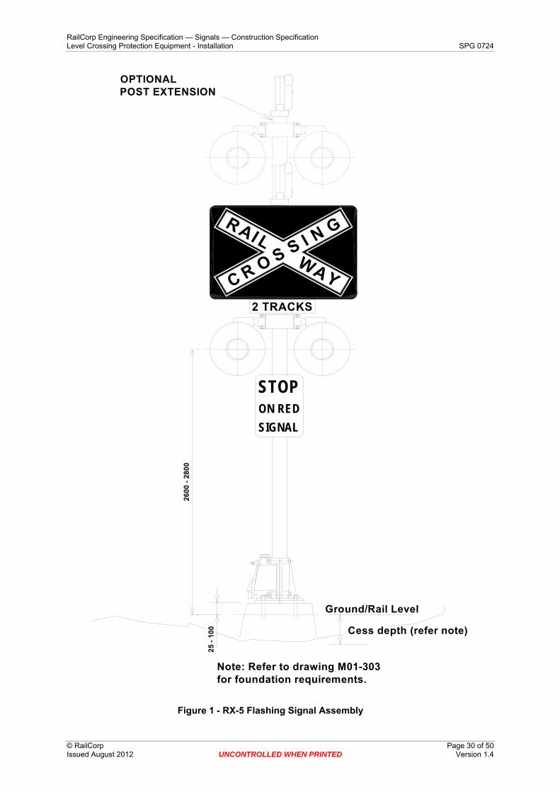
RTA Roads & Traffic Authority.
RX-5 Flashing Signal Assembly As defined in AS1742.7: 2007. Also referred to as an ‘RX-5 Assembly’ in this document. Refer to Appendix A Figure 1. Also commonly known as a ‘Type-F Assembly’.
RX-5 Flashing Signal Assembly with Road Boom Also referred to as an ‘RX-5 Assembly with Boom’ in this document. Refer to Appendix A Figure 2.
Shared use crossing refers to a crossing which is designated for use by both pedestrians and cyclists. The crossing is typically double the width of a standard crossing and incorporates four swing gates. Pedestrians include persons using mobility aids such as wheelchairs and disability scooters.
Urban The term meaning country or non suburban built up areas.
4.1 Operation, Testing and Commissioning of level Crossing protection The level crossing protection specified herein shall operate in accordance with the principles and circuits in Specifications ESG 100.0, ESG 100.18 and SDG 001 and shall be tested and commissioned in accordance with specifications SPG 711.5 and SPG 711.6.
The following forms located in SPG 0711.7 ‘Inspection And Testing Of Signalling Standard Forms’, are also to be used with the construction and commissioning of Level Crossings: -
a) Level Crossing Site Inspection Form.
b) Level Crossing Site Inspection.
c) Stakeholder Site Inspection and Authority to Commission.
d) Gated Pedestrian Crossing Assessment Sheet.
4.2 Warranty Completed level crossing protection systems shall be warranted free of defect in installation for a period of 12 months from the date of commissioning.
All of the equipment installed, including consumables, shall be warranted as complying with this or any referenced specification and as being fit for purpose.

RailCorp Engineering Specification — Signals — Construction Specification Level Crossing Protection Equipment - Installation SPG 0724
© RailCorp Page 10 of 50 Issued August 2012 UNCONTROLLED WHEN PRINTED Version 1.4
4.3 Quality The standard of materials and workmanship, including the workmanship involved in installation, shall ensure that the installed system is fit for purpose over the lifetime of the asset in its physical and operational environment.
Quality of materials and workmanship shall also ensure that the necessity for regular preventative maintenance tasks to retain the safety, reliability and useability of the asset over its lifetime is minimised.
5 Road Crossings
5.1 General For each public access level crossing it shall be necessary to come to an agreement with the Roads and Traffic Authority or local road authority and other stakeholders as to, but not limited to :-
a) Any necessary improvements to road approach alignment or surface
b) The layout of the equipment
c) The type of protection and number of signals
d) Provision of kerbing and/or delineation
e) The requirement for Advance Warning Lights
f) The provision and installation of road signage outside the railway boundary
g) Traffic Light Interface.
In consultation with the sighting committee, site specific circumstances may determine a need for auxiliary light stands in addition to the main lights.
On reaching agreement, site plans and or site minutes detailing the proposed crossing layout shall be signed off by all involved parties.
Level crossing signals and signage installation for each level crossing shall comply with Australian Standard 1742 Part 7, additional drawing(s), specifications and site plan(s) issued by RailCorp. RailCorp standards shall take precedence.
5.2 Services Where relocation of any service (e.g. water, gas, electricity etc.) is required, arrangements shall be made with the owner to have the relocation carried out.
If for any reason relocation of the service is found to be impractical, alternative proposals to avoid or span the service need to be considered.
5.3 RX-5 Assembly - Posts (Masts) The RX-5 Assembly post arrangement shall comply with drawing M06-269.
For the RX-5 Assembly with Boom, the post arrangement shall comply with drawing M06-203 .
Refer to Figure 1 and Figure 2 for examples.

RailCorp Engineering Specification — Signals — Construction Specification Level Crossing Protection Equipment - Installation SPG 0724
© RailCorp Page 11 of 50 Issued August 2012 UNCONTROLLED WHEN PRINTED Version 1.4
Cantilever posts or gantries over roads will only be permitted where a clear safety improvement can be demonstrated, on approval of the Chief Engineer Signals and the Chief Engineer Electrical.
5.4 RX-5 Assembly Mast Installation RX-5 Assembly masts and RX-5 Assembly with Boom masts on each side of the level crossing shall be positioned such that no part of the centerline of the masts, or boom tip is closer than 3.5 metres from the nearest rail.
To allow sufficient clear space for safe maintenance access of the mechanism and counterweights, no infrastructure such as fencing, shall be permitted to be located within 2 metres of the rear of the centreline of the boom gate mast. The rear being defined as the side where the mechanism is fitted to the post.
Where overhead cables are located within 3m (for voltages up to 132kV) horizontally of a proposed boom post, the supply authority shall be contacted to determine the required safe horizontal and vertical clearances from the boom tip. In some circumstances this may require the OHW to be relocated or run underground.
Where the boom is considered to be of sufficient length so as to be able to fall when struck, into the 1500Vdc OHW traction line, a boom of fibreglass construction in lieu of the standard aluminium/fibreglass composite construction, may be considered.
The position of the light or boom mast relative to the road edge, edge marking or kerb will depend on:-
a) The road approach speed, which will define the “clear zone”1
b) Any physical restrictions imposed by the site
c) Vehicle drivers sighting of the lights
d) Boom arm length limits.
In most instances, site restrictions and/or sighting requirements and/or limiting boom lengths will necessitate placing the masts within the clear zone.
Where this is the case, a documented risk analysis shall be carried out to determine the best method of minimising the risk posed by the mast. This may take the form of barrier kerbing or delineation or both. Since space restrictions at level crossings usually preclude the installation of adequate guardrail end protection sections, ‘W’ style (Armco) guard rails cannot be used to protect the installation from errant motor vehicles.
Where non-frangible equipment is to be placed within the ‘clear zone’, guidance should be sought from the local road authority and/or latest version of the RTA Road Design Guide. Refer to document titled ‘Traffic Engineering Manual, Section 6. Safety Barriers for Roads and Bridges, Road Design Guide, May 1996.’
1 The “clear zone” is the distance from the road edge or edge marking which is, whenever possible, to be maintained clear of obstructions. This provides an area in which a vehicle can run off the road and recover.
2 Elsholz Redirective Kerb is suitable for low impact angles <15° in 60 to 70km/h speed zones.

RailCorp Engineering Specification — Signals — Construction Specification Level Crossing Protection Equipment - Installation SPG 0724
© RailCorp Page 12 of 50 Issued August 2012 UNCONTROLLED WHEN PRINTED Version 1.4
While there is a reduction in rigidity provided by the cast aluminium mast base, this arrangement cannot necessarily be classed as “frangible” and on suburban roads supplementary protection shall be provided in the form of barrier kerbing.
Consideration should be given to the use of Elsholz Redirective Kerb2 at the boom posts in suburban environments. Redirective kerb may only be installed with the approval of the local road authority.
Figure 3 to Figure 8 provide guidance on positioning of masts and delineation relative to the road edge for installations in suburban roads with a speed ≤ 60kph. As an absolute minimum, the centre line of the light / boom standard shall never be less than 1450mm from road edge, road edge being defined as rising edge of kerb as applicable to Figure 3.
Figure 9 and Figure 10 provide guidance on positioning of masts and delineation relative to the road edge for installations in urban roads with a speed >60kph.
Where site conditions require the installation of additional (auxiliary) light standards in urban areas without kerbs, as an absolute minimum, the centre line of the light standard shall not be less than 2500mm from road edge, road edge being defined as edge of bitumen or fog line. Guidepost and or kerb delineation treatments shall be determined as per Section Error! Reference source not found.. The road offset of 2.5m should only be a consideration if the 3.5m desirable offset cannot be achieved - reduced offsets will increase the probability of a vehicle impact with the installation.
5.5 RX-5 Assemblies
5.5.1 Flashing Signal Lanterns RX-5 Assemblies are typically available in two lantern (uni-directional) and four lantern (bi-directional) form.
Note that for level crossings without booms, where front and back lanterns must be sharply angled to one another, the assemblies shown for boom installations may be required to achieve the required angle.
The centre of the lanterns shall be 2600 – 2800mm above rail level.
Additional crossarms, where required, shall be mounted a minimum of 625 mm above the basic crossarm assembly.
Where a retro-fit post extension is required, it shall be manufactured according to drawing M06-257.
A typical RX-5 Assembly is shown in Appendix A Figure 1.
At level crossing sites with traffic light controlled intersections located immediately before and or after the level crossing, where a safety improvement can be demonstrated, on approval of the Chief Engineer Signals, the mounting of a traffic signal with red/yellow aspects only, may be permitted on the RX-5 Assembly post. In the foregoing configuration, the boom with mechanism would be mounted on a separate post. Refer to drawing M06-266 for construction guidelines.

RailCorp Engineering Specification — Signals — Construction Specification Level Crossing Protection Equipment - Installation SPG 0724
© RailCorp Page 13 of 50 Issued August 2012 UNCONTROLLED WHEN PRINTED Version 1.4
Note: Incandescent light units are not to be used for new works or upgrading of existing works.
5.5.2 Booms and Boom Lights The nominal length of a boom shall be measured from the centre line of the post, on which the mechanism is mounted, to the tip of the boom.
Unless otherwise stipulated in the particular specification, the tip of the boom shall not be closer than 200 mm to the centre line of the carriageway for undivided roads and not beyond the near or far edge of the median strip on divided roads.
Refer to drawing M06-249 for standard boom kit selection and drawing M06-240 for light spacing guidelines.
The gate mechanism shall be mounted so that the bottom of the boom arm in the horizontal position will be between 1000 and 1250mm above road level. Refer to drawing M06-203 for general arrangement details.
A typical RX-5 Assembly with boom is shown in Appendix A Figure 2.
Where boom length exceeds 7.25m or approved boom skirts are fitted, a high wind support shall be fitted to the gate mast.
Where boom length exceeds 9140mm, an approved Buffer Leg Assembly shall be fitted to the tip of the boom and a High Wind Bracket fitted to the mast.
Boom lights shall be visible to road traffic on both sides of the level crossing but preferably not to the train driver.
The boom lights shall be positioned on the boom such that each traffic lane has at least one light in it.
Note: Incandescent light units are not to be used for new works or upgrading of existing works.
5.5.3 Enlarged Background When the road alignment is such that the sun will rise or set behind the level crossing signals when viewed from the road approaches, a large one piece background as detailed in drawing M06-258 may be fitted to the RX-5 Assembly. This background shall be additional to the standard backgrounds fitted to the light units. One only background is required per pair of flashing signal lanterns.
5.6 Audible Warning Devices Audible alarms/warnings shall take the form of bells and provide an additional warning to the visual warning provided by red lights. The effective audible range of the warning is determined by whether vehicles windows are open and or sound systems etc are operating. Audible warnings are increasingly, primarily provided for the purpose of warning pedestrians.
Bells may be either solid state (electronic) or mechanical in their design.
The Western-Cullen-Hayes model 0777 electronic bell needs to be set to maximum volume in order to replicate the standard mechanical bell sound level. Refer to Specification SPG 0723 for options and adjustment detail.

RailCorp Engineering Specification — Signals — Construction Specification Level Crossing Protection Equipment - Installation SPG 0724
© RailCorp Page 14 of 50 Issued August 2012 UNCONTROLLED WHEN PRINTED Version 1.4
Mechanical bells are normally fitted with a metal hammer. A nylon hammer option is available from RailCorp Stores for reducing the sound level in approved instances. Refer to Specification SPG 0723 for further details.
Where suppression of audible warning devices is considered necessary, the arrangement shall comply as permitted under Design Principles document ESG 100.18.
Where there is no bell mounted on top of the post, pipe sealing caps shall be provided.
5.7 Signage Refer to AS1742.7 for general information on the below-referenced standard signage types:-
a) R6-24A, R6-25B, W7-2-2A, R6-9, W7-4B and 4C, W7-14-3, D4-3, G9-58, G9-67-2 and RX-9.
b) Rail Authority Basic Signage.
The minimum requirement for active crossing signage shall be:-
a) "Railway Crossing" sign R6-25B (often described as the ‘Confederate flag’ version), shall be supplied to drawing M06-263. One on each side of the level crossing mounted on the RX-5 Assembly post. Note: The alternative style "Railway Crossing" sign R6-24A together with the "Tracks" sign W7-2-1A may be used for high wind applications such as on the tip of an overhead cantilever post.
b) "Tracks" sign W7-2-2A shall be supplied to drawing M06-212. One on each side of the level crossing mounted on the RX-5 Assembly post. Refer note below.
c) "Stop On Red Signal" sign R6-9 shall be supplied to drawing M06-212. One on each side of the level crossing mounted on the RX-5 Assembly Post.
d) Train Drivers Approach sign W7-4B shall be supplied to drawing M06-213. One on each railway approach to the level crossing at the point at which the train initiates the level crossing operation.
e) Level Crossing identification sign in accordance with SPC 521 located on the level crossing hut clearly visible to road users.
D4-3 width markers may be required where the conspicuity of the crossing needs to be enhanced. Civil discipline is responsible for RX-9 and D4-3(L & R) width marker signs. These signs are generally required where the road lane at the crossing reduces in width, at crossings located on sharp curves, where a pedestrian crossing or other equipment is located close to or on the edge of a road without kerb and guttering and within the clear zone and at urban crossings. Refer to examples in Appendix A Figure 8 to Figure 10.
Where D4-3 width markers are required, they shall be installed to both sides of the road, both sides of the crossing.
Refer to examples in Appendix A Figure 8 and Figure 10.
5.7.1 Road Authority Signage The Road Authority responsible for the particular road(s) involved, provides guideposts, approved barrier kerbs and additional road approach signage.

RailCorp Engineering Specification — Signals — Construction Specification Level Crossing Protection Equipment - Installation SPG 0724
© RailCorp Page 15 of 50 Issued August 2012 UNCONTROLLED WHEN PRINTED Version 1.4
As a minimum, ensure that the Road Authority provides approach warning sign W7-4B or C, one on each side of the level crossing, placed where shown in AS1742.7.
Ensure that the Road Authority provides G9-67-2 ‘Keep Tracks Clear’ signage where applicable. When issued by RailCorp, the ‘Keep Tracks Clear’ sign shall be supplied to drawing M06-212.
Refer to examples in Appendix A Figure 6 and Figure 7.
5.8 RX-5 Assembly Foundations The top of the foundation is to be between 25 and 100mm above ground level.3 Also refer to Figure 1 and Figure 3 for guidelines.
5.8.1 Posts without Boom Pre-cast foundations for 114mm O.D. RX-5 light posts shall be in accordance with the latest version of drawing M01-301. Foundation bolts shall be not less than 24mm diameter for signals on 114mm O.D. posts.
5.8.2 Posts with Boom Mainline 140mm O.D. signal post foundation designs are generally suitable for RX-5 light posts with boom less than 9.2m long and mast height less than 4m.
Pending assessment of local ground conditions, for 140mm O.D. RX-5 light posts with boom up to 12m long, refer to table on drawing M01-310 for guidance.
5.9 Road Pavement Markings RailCorp has adopted the requirements of AS1742.7 and applied them to private and public level crossings.
Pavement markings shall comply with AS1742.7 and shall be used on sealed roads on approaches to, and at, railway level crossings, as applicable.
Ensure that the Road Authority provides:-
a) Holding / Stop Line, to indicate the safe position for vehicles to stop, to avoid conflict with a train. Refer to example sketches in Appendix A.
b) ‘RAIL X’ pavement marking, where required.
c) No overtaking lines on the approaches to and over the crossing where applicable.
d) Box markings (queuing) where applicable. Where box markings are installed, ‘Keep Tracks Clear’ signage is required. Refer to examples in Appendix AFigure 6 and Figure 7.
3 Ground level is taken at the position of the foundation. This may be above or below road level. In country locations, ground level is usually taken as top of rail.

RailCorp Engineering Specification — Signals — Construction Specification Level Crossing Protection Equipment - Installation SPG 0724
© RailCorp Page 16 of 50 Issued August 2012 UNCONTROLLED WHEN PRINTED Version 1.4
5.10 Cable Trenching Cable trenching, under-line and under-road crossings for cable/wiring to Flashing Signal Lanterns, boom mechanisms and any equipment associated with the control and operation of the level crossing shall be to the requirements of RailCorp specification SPG 0705.
Cable trenching from the level crossing location to Advance Warning Lights shall be to the requirements of AS 3000.
5.11 Alignment of Flashing Signal Lanterns
5.11.1 Requirement Flashing Signal Lanterns shall be aligned to provide the drivers of road vehicles with the maximum possible warning of the stop indication commensurate with the road speed limit approaching and over the level crossing.
The motorist must be able to sight the warning indication, either the Flashing Signal Lanterns or the Advance Warning Lights at a safe stopping distance from the level crossing.
Safe stopping distances, which include driver’s reaction times, are:-
Vehicle Speed (kph)
Safe Stopping Distance (m)
Sighting Distance (m)
Car Semi Trailer B-double 40 45 65 67 - 60 77 116 120 130 70 - - - 175 80 120 184 191 200 90 - - - 250 100 175 275 286 300 110 - - - 300 120 250 - - -
Table 1
For most straight or near straight approach conditions the left side lanterns facing approaching traffic are to be focused for the long range view. The back lanterns of the signal on the other side of the crossing are to be focused for the short range view and for a vehicle(s) stationary at the stop line.
Typical focusing plans are shown in Appendix B (incandescent lights) and Appendix C (LED lights).
For multi-lane roads, both the left side lanterns and any lanterns on the median strip or on the front of a cantilever / gantry are to be focused for the long range view. Back lanterns on the signals on the other side of the crossing and back lanterns on a gantry or median strip are to be focused for the short range view and for a vehicle stationary at the crossing.
Where it is not possible for the front lanterns to be aligned for the long range view due to road geometry, any additional crossarms provided, whether on the same post, a separate post or a gantry are to be used for the long range view.
RailCorp Engineering Specification — Signals — Construction Specification Level Crossing Protection Equipment - Installation SPG 0724
© RailCorp Page 17 of 50 Issued August 2012 UNCONTROLLED WHEN PRINTED Version 1.4
As the motorist must sight the lanterns at safe stopping distance, the front lanterns shall be aligned so that the axis of the beam intersects the road at that distance.
Where the approach to the level crossing is curved or over a crest, the degree of curvature and the blocking effect of the crest shall determine whether additional crossarms or post assemblies, cantilevered arms or Advance Warning Lights are required to provide visibility to the motorist at the safe stopping distance from the level crossing.
Where possible obtain vehicle approach speed information from the Roads and Traffic Authority. This will be the 85th percentile speed for the section of road leading to the crossing.
If this information is not available, for straight roads use the speed limit, for curved approaches use advisory speed signs and add 20 to 25%. Eg if the advisory is 75kph assume an approach speed of 90 – 95kph.
(Note: The road speed within 50 or so metres of the crossing should not be used to estimate vehicle approach speed. Eg if a road with a 100 kph speed limit parallels the railway then turns sharply to cross the line, do not use the curve speed to estimate vehicle approach speed. A vehicle may be able to negotiate the curve to the crossing at say 45 kph but would need to be at 25 - 30 kph entering the curve to be able to stop safely before the crossing).
5.11.2 LED Flashing Signal Lantern Alignment Procedure Three persons (including one to act as the viewer’s lookout for road traffic) are required to align level crossing Flashing Signal Lanterns.
Note: On roads with heavy traffic it will probably be necessary to obtain RTA assistance to stop traffic while alignment is being carried out.
The alignment must be carried out in daylight.
The person aligning the lantern should first approximately align each lampcase to point towards the viewer with the indication beam approximately horizontal.
The lantern should then be rotated side to side and up and down until the viewer indicates the position of maximum visibility.
With curved road approaches, the viewer should then walk back towards the level crossing checking the visibility of the lanterns throughout the curve.
If there is significant loss of sight of the lanterns, then the lampcases will need to be re-aligned to compensate even if this slightly reduces the intensity at the original viewing point.
If the loss of intensity is such that the lanterns cannot be aligned to provide full coverage from the required sighting distance over the approach to the crossing, then either additional lanterns at the level crossing are required or Advance Warning Lights are required.
It is not necessary to make any special provision for the height of the viewer. A standing person’s eye level is a reasonable compromise between the eye levels of car and heavy commercial vehicle drivers.
RailCorp Engineering Specification — Signals — Construction Specification Level Crossing Protection Equipment - Installation SPG 0724
© RailCorp Page 18 of 50 Issued August 2012 UNCONTROLLED WHEN PRINTED Version 1.4
Lanterns are to be checked for clear visibility4 under bright sunlight conditions with the sun directly above.
5.11.3 Incandescent Flashing Signal Lantern Alignment Procedure The alignment procedure shall be as per the above LED alignment procedure with the following exceptions:-
For straight road approaches, the level crossing lantern lampcase door, on the front lanterns only, should be opened and the lantern aligned directly from the lamp and reflector.
For curved approaches, particularly those sharp enough to require a 70 degree spread lens in the front lanterns, and for the back lanterns, the level crossing lanterns should be aligned with the lampcase door closed.
Note: Incandescent light units are not to be used for new works or upgrading of existing works.
5.11.4 Front Lanterns The person who is to view the lanterns shall do so from the distance nominated in section 5.3.1 for the road speed limit applying to the approaches to the level crossing or at the maximum available sighting distance, whichever is less. The viewer should be positioned;-
a) 1 -1.2 meters to the left of the road centre line, for two lane roads, and
b) Approximately 1 metre to the right of the lane dividing line for four lane roads.
For four lane roads both the left hand side front lanterns and the median strip front lanterns should be aligned to the same point.
5.11.5 Back Lanterns For LED lanterns, the viewing position should be 10 to 15 metres ahead of the stop line. Refer to typical situation Figure 15 to Figure 19 in Appendix C for indicative beam visibility patterns.
For incandescent lanterns, the viewing position should be as shown on the typical situation Figure 12, Figure 13 and Figure 14 in .Appendix B.
For four lane roads, the median strip back lanterns [if fitted] should be aligned to the left lane and the opposite side back lanterns aligned for the right lane.
4 While LED lanterns must meet the specified visibility distances for bright daylight conditions, intensity shall not be so high that significant impairment to night vision is caused to a motor vehicle driver approaching the crossing at night.

RailCorp Engineering Specification — Signals — Construction Specification Level Crossing Protection Equipment - Installation SPG 0724
© RailCorp Page 19 of 50 Issued August 2012 UNCONTROLLED WHEN PRINTED Version 1.4
5.12 Advance Warning Lights
5.12.1 Application Advance Warning Light (AWL) and sign assemblies are intended for use under the following circumstances:-
a) Where it is not possible for the motorist to see the flashing signal lanterns at the level crossing at the safe stopping distances specified in Table 1.
b) The level crossing is subject to severe fog conditions and the road approach speed is more than 60 kph.
c) There are special circumstances such as a sharp down hill approach which would extend vehicle braking distances or regular queuing back from the crossing being hidden by a crest.
d) There is a very long, straight flat approach to the level crossing and motorist’s reaction times are likely to be longer than normal.
The larger assembly, detailed on RailCorp drawings M06-400 and M06-401 is intended for highway and major road application where the road vehicle approach speed is 80 kph or higher.
The smaller assembly detailed on RailCorp drawings M06-403 and M06-404, is intended for secondary roads or where the road vehicle approach speed is less than or equal to 80 kph.
A variation on the smaller sign, detailed on RailCorp drawings M06-405 and M06-406, is intended for applications where it is necessary to provide early warning of activation of a level crossing on a side road where there is a very short distance between the stop line and the road intersection.
Note: Incandescent light units are not to be used for new works or upgrading of existing works.
5.12.2 Installation/Location Guidelines The AWL assembly shall normally be installed to the left of the roadway but may, if necessary to provide adequate sighting around a left bend, be installed on the right hand side.
In rural areas without kerbs:-
a) The AWL assembly should be located so that the edge of the sign is not less than 2 metres or more than 5 metres from the road edge.
b) If there is a safety barrier system alongside the road, the edge of the sign should not be less than 600mm from the front of the barrier system.
c) The bottom of the sign should be 1.5 metres minimum above road level.
If in a kerbed area:-
a) The edge of the sign should not be less than 600mm from the kerb and
b) If over a formal footpath, the bottom of the sign must be 2.5 metres above the path.

RailCorp Engineering Specification — Signals — Construction Specification Level Crossing Protection Equipment - Installation SPG 0724
© RailCorp Page 20 of 50 Issued August 2012 UNCONTROLLED WHEN PRINTED Version 1.4
c) Support posts must be clear of the path.
Foundations shall be according to drawing M06-407.
Note:
Depending on the site, AWL assemblies may be installed and/or maintained by the Road Authority or by RailCorp. Refer to RTA/RailCorp interface agreement titled ‘Interface Arrangements for the Installation and Maintenance of Joint Rail & Road Structures & Cabling at Level Crossings’.
RailCorp AWL assemblies shall be assembled according to the applicable above-referenced drawings.
5.12.3 Cabling The cable from the level crossing location to the AWL shall be 3 core + earth power cable to AS 5000 parts 1 or 2 as applicable and shall be of the cross sectional area specified in Table 2. Underground conduit should be no less than 80mm diameter.
Distance from Level Crossing
Assumed Cable Length Conductor Size Comment
200m 450m 6 sq. mm 250m 550m 6 sq. mm 300m 650m 6 sq. mm 10 sq. mm Preferred size 350m 750m 10 sq. mm 400m 850m 10 sq. mm
Table 2 AWL Cable Conductor Sizes
5.12.4 Distance from the Level Crossing It shall be possible for the motorist to sight the Flashing Signal Lanterns at the level crossing from the AWL location or very shortly afterward so that a continuous warning is provided.
To achieve continuous or near continuous warning, the AWL shall be placed slightly inside the point at which clear sighting of the lanterns at the crossing is lost.
If this location is unsuitable due to restrictive sighting of the AWL or because there is insufficient space to locate the sign, the AWL may be moved further from the crossing by:-
a) 30 m for 60 kph approach speed
b) 45 m for 80 kph approach speed
c) 55 m for 100 kph approach speed
Except where it is found necessary for two AWL assemblies to be provided, the maximum distance from the crossing to the warning lights should not exceed 350 m.
A W7-4 sign, at least, should always precede the AWL assembly.
A typical example of the location of the AWL assembly over a crest, is shown in Appendix C Error! Reference source not found..

RailCorp Engineering Specification — Signals — Construction Specification Level Crossing Protection Equipment - Installation SPG 0724
© RailCorp Page 21 of 50 Issued August 2012 UNCONTROLLED WHEN PRINTED Version 1.4
5.12.5 Alignment Both lights in the AWL assembly should be aimed 175 - 200m in front of the assembly for 80 kph and above and 100 to 125m for 60kph or to the maximum available sighting distance if this is less. Lampcases shall be level or tilted slightly downward.
The viewing face of the AWL assembly sign shall be aligned 5º past perpendicular to the direction of approaching road traffic. I.E. rotated approximately 5º away from the normal, to a line adjoining the edge of the roadway.
6 Pedestrian Crossings Guidelines to the level of protection to be applied to pedestrian crossings, both independent crossings and those associated with roadways, is given in RailCorp Civil Engineering Standard ESC 520.
Local considerations may, however, determine that a higher level of protection than indicated by the guidelines is necessary.
Crossings shall comply with the forms specified in AS1742.7 with exceptions as detailed in sections 5.1 and 5.2 below.
6.1 Standard Crossings Actively protected standard pedestrian crossing layouts shall take the form defined as follows:-
a) Layouts shall comply with detailed construction drawing M06-244.
b) No portion of the level crossing corral fencing shall be closer than 2500mm from the nearest rail.
6.2 Special Purpose Crossings A ‘shared use’ special purpose crossing shall take the form defined as follows:-
a) ‘Shared use’ pedestrian crossings shall comply with the requirements defined in drawing M06-271. Also refer to Figure 11 Appendix A for a typical layout example.
b) The closest point of the crossing (fence), is to be a minimum 1500mm from the nearest rail (Refer to drawing M06-244 Sheet 3).
c) ‘Shared use’ pedestrian crossings shall always be installed perpendicular to the track.
Derivations from the standard form for ‘shared use’ crossings may be permitted on application to the Chief Engineer Signals.
6.3 Pedestrian Gates Swing gate mechanisms are the preferred method of providing protection at pedestrian level crossings where protection additional to the “Don’t Walk” lights is required.
Where a motorised swing gate is provided, an emergency exit route with self closing self latching swing gate shall be provided.

RailCorp Engineering Specification — Signals — Construction Specification Level Crossing Protection Equipment - Installation SPG 0724
© RailCorp Page 22 of 50 Issued August 2012 UNCONTROLLED WHEN PRINTED Version 1.4
6.3.1 Swing Gate Motor Mechanism Refer to drawing M06-251 for installation details of gate.
6.3.2 Emergency Exit Swing Gate Refer to drawing M06-274 for installation details of mechanical latch release gate.
Refer to drawings M06-248, M06-255 and M06-256 for installation details of electrical latch release gate.
6.3.3 Posts Posts shall be galvanised protected against corrosion to achieve the required life span without the need to renew the protective coating. “Duragal” type posts are acceptable.
6.4 Fencing Fencing for gated and maze crossings shall be 1.5m high weld mesh as defined in drawing M06-244. Note that non standard corral fencing may be considered in some circumstances such as heritage sensitive areas, on application to the Chief Engineer Signals.
Fencing leading up to a crossing corral (gated or maze) shall not be less than 1.0m in height and where associated with existing station platform fencing, should match that fencing. Note that boundary fencing should not be less than 1.8m in height.
Refer to Civil specification ESC 510 for boundary fencing requirements.
6.5 Signage The signs to be displayed at pedestrian gated crossings shall be according to the latest version of AS1742.7 with the exception of the following:-
a) "Warning" signs W7-14-3 which shall be manufactured according to drawing M06-215.
b) "Cyclists Dismount" sign G9-58 which shall be manufactured according to drawing M06-262.
c) “Cycle Hazard” sign which shall be manufactured according to drawing M06-272.
6.5.1 Rail Authority Basic Signage The minimum requirement for gated control pedestrian crossing signage is detailed in drawings M06-244 and M06-270, and shall consist of:-
a) "Warning" sign W7-14-3 (refer to drawing M06-215), one on each side of the level crossing, either post or fence mounted in positions where they can be best viewed by approaching pedestrians.
b) "Emergency Exit" sign (refer to drawing M06-247), one on each side of the level crossing, gate mounted.
c) "No thoroughfare" sign (refer to drawing M06-244), one on each side of the level crossing, gate mounted.

RailCorp Engineering Specification — Signals — Construction Specification Level Crossing Protection Equipment - Installation SPG 0724
© RailCorp Page 23 of 50 Issued August 2012 UNCONTROLLED WHEN PRINTED Version 1.4
d) "Emergency Exit Arrow" sign (refer to drawing M06-247), one on each side of the level crossing, gate mounted.
e) "Cyclists Dismount" sign G9-58 (refer to drawing M06-262), one on each side of the level crossing, either post or fence mounted.
f) Level crossing identification sign in accordance with SPC 521 located on the fence for each pedestrian approach.
Active maze crossing signage requirements are also detailed in drawing M06-244.
Where a pedestrian crossing is provided on one side of a road only, ensure that signs stating ‘No Pedestrian Access’ (RailCorp Stock Code 2059632) are installed at the opposite side of the road at the road verge where pedestrians are not permitted to cross the track. Refer to example in Appendix A Figure 3.
Note: The use of landscaping approved by the local road authority may assist in deterring illegal access to the rail corridor.
6.5.2 Special Purpose Crossing Signage An example of an approved special purpose crossing, is the ‘shared use’ crossing.
‘Shared use’ crossings require special signage treatment, where the ‘Cyclists Dismount’ signage is replaced by ‘Cycle Hazard’ signage.
Guidance on positioning signs is provided in drawing M06-271.
6.6 Audible Alarms Audible alarms/warnings may take the form of bells or tone generators. Typically tone generators are fitted, and may be supplemented by bells where the crossing is associated with an adjacent active road crossing.
6.6.1 Bells Refer to section 3.6 for information on bells.
6.6.2 Tone Generators At least one tone generator shall be fitted each side of the crossing.
Older Klaxon brand tone generators are directional and can be recognised by their square shape. Care shall be taken to ensure that directional tone generators are adjusted to face towards pedestrians approaching from the opposite side of the crossing and, in so far as possible, away from any residence in the vicinity.
More recent tone generators are omni-directional which can be recognised by their cylindrical shape.
The volume of tone generators is internally adjustable, and in order to achieve adequate sound levels, the omni-directional style of tone generators shall be set to maximum volume. Refer to construction drawing M06-244 and drawings M06-251 or 253 for model and adjustment instructions.

RailCorp Engineering Specification — Signals — Construction Specification Level Crossing Protection Equipment - Installation SPG 0724
© RailCorp Page 24 of 50 Issued August 2012 UNCONTROLLED WHEN PRINTED Version 1.4
6.6.3 Gated Crossing The tone generator shall be mounted within the pedestrian swing gate mechanism enclosure. Refer to assembly drawing M06-251 for details.
6.6.4 Active Maze Crossing The tone generator shall be mounted in the top of the light post within the vandal resistant post-top cap. Refer to assembly drawing M06-253 for details.
6.7 ‘Don’t Walk’ Light Units Light Units for crossings whether fitted with lights only or with swing gates shall be ‘DONT WALK’ (Red Man) lights. Unless otherwise specified, there shall be two lights on each side of the crossing, one light adjusted to face oncoming pedestrians and the other light adjusted to face across the railway tracks.
‘Don’t Walk’ lights shall be LED illuminated.
Approved lights are specified in drawings M06-251 or 253.
6.7.1 Gated Crossing ‘Don’t Walk’ (Red Man) lights shall be mounted on the motorised gate post.
Refer to drawing M06-251 for light mounting details.
6.7.2 Maze Crossing ‘Don’t Walk’ (Red Man) lights shall be mounted on the light post.
Refer to drawing M06-253 for light mounting details.
6.8 Foundations Refer to drawing M06-244 for minimum standards and details of concrete foundations for gate posts, fence posts and ‘don’t walk’ light posts.
6.9 Walking Surface Treatments Public pedestrian crossing ground surfaces shall comply with the minimum requirements defined in RailCorp construction drawing M06-244, AS1742.7 and RailCorp Civil Standard ESC-520.
Where the surfaces cross the tracks, durable removable panels are preferred, in order to enable tamping and maintenance.
Slip resistant classification requirements are as detailed in Civil Standard ESC-520.
Exposed continuous metal frames are not permitted in ground surface panels, as they have the potential to allow vandals to short circuit the track.
Surface joints such as expansion joints and abutting surfaces shall not protrude vertically by more than 5mm with any protruding surface having a rounded shape. The change in level between rail and adjacent footpath shall not be more than 5mm.
Walking surface gradients shall be as detailed in Civil Standard ESC-520 and RailCorp construction drawing M06-244.

RailCorp Engineering Specification — Signals — Construction Specification Level Crossing Protection Equipment - Installation SPG 0724
© RailCorp Page 25 of 50 Issued August 2012 UNCONTROLLED WHEN PRINTED Version 1.4
6.9.1 Warning Tiles Warning Tactile Ground Surface Indicators (TGSI) shall be provided:-
a) at the shoulders on both sides of the crossing over the tracks. Tactile strip shall be 300mm wide, refer to drawing M06-244 for details.
b) across the full width of the corral at the point where the person is leaving the safe haven and at 90 degrees to the direction of travel across the crossing. Tactile strip shall be 600mm deep by the width of the opening in the corral, refer to drawing M06-244 for details.
c) at ‘Shared Use’ special purpose crossings for delineation over the track. Tactile strip shall be 300mm wide, refer to drawing M06-271 for details.
TGSI’s shall be non slip and coloured ‘Safety Yellow’ / ‘Sunflower Yellow’.
TGSI’s shall be installed according to procedures detailed on construction drawing M06-244.
6.9.2 Special Purpose Crossings Special purpose ‘shared use’ crossings shall be line marked as shown on drawing M06-271 which includes continuous (no overtaking) delineation lines and direction arrows.
Note: Check that cyclist and pedestrian symbols are provided either side of the crossing corrals, by the local authority.
6.10 Rail Flange gap Flange gap shall be maintained at a limited maximum depth and width as detailed in Civil Standard ESC-520 and as defined in AS1742.7.
6.11 Provision of Area Flood Lighting Artificial lighting of pedestrian crossings is required to enable crossing users to read warning signage, stay on the pathway and observe any immediate hazards.
Area lighting design within the rail corridor is the responsibility of the Electrical discipline.
Outside of the rail corridor, the Road Authority or Local Council usually provide flood lighting where deemed applicable.
6.11.1 Performance Requirements Detailed performance requirements for lighting at pedestrian level crossings are not presently defined. The following information is provided for reference:-
a) Colour temperature shall be no less than 4000k Metal Halide Lamp, i.e. a white daylight colour.
b) Lighting intensity shall be no less than 45 Lux (measured at ground level) on the pathway over the tracks, within the crossing corrals, on access ramps and access paths as per the requirements of AS 1158.1 and AS1148.4.
c) Luminare shall be an approved ‘cut-off’ style to reduce glare to train and road vehicle drivers.

RailCorp Engineering Specification — Signals — Construction Specification Level Crossing Protection Equipment - Installation SPG 0724
© RailCorp Page 26 of 50 Issued August 2012 UNCONTROLLED WHEN PRINTED Version 1.4
d) The lamp stand and luminare should be placed outside the 3m danger zone in order to allow maintenance to be carried out on the luminare.
6.11.2 Application Guidelines Guidelines are based on standard practice using the lamp stand assembly to drawing M06-254 with approved cut-off style luminare incorporating one 150W MH lamp.
For a two track crossing in a built up suburban area:-
a) Generally, one luminare on each side of the track pointed in the direction of the center of the six foot will provide the minimum 45 Lux at the center of the crossing. The lamp post is normally located just outside the 3m zone.
b) Additional lighting will be necessary to cover each corral and typically one luminare is provided for each corral.
For a single track crossing in a low density urban area:-
c) Generally one luminare on one side of the track pointed in the direction of the center of the track will provide the minimum 45 Lux. The lamp post is normally located just outside the 3m zone.
d) Additional lighting will be necessary to cover the corral areas and typically one luminare is provided for each corral.
7 Test, Emergency & Manual Operation Boxes Every crossing shall be equipped with test, emergency and manual operation boxes. For associated road and pedestrian crossings, common test and emergency boxes shall operate both.5
The test and emergency boxes shall operate in accordance with the requirements of Standard Specification ESG 100.0 and ESG 100.18.
8 Level Crossing Equipment Housing Equipment for the control and operation of the level crossing shall be housed in a pre-cast concrete walk-in location6 complying with Specification SPG 0708 and located adjacent to the level crossing.
This building shall be positioned not less than 15 metres from the edge of the roadway and as close to the railway boundary as practical to reduce exposure in the event of an accident and to reduce obstruction to the line of sight of an approaching train.
The level crossing location shall be provided with an identification plate. The plate shall be visible from the track and shall state the locality name and the kilometreage of the
5 Design and functionality is presently being reviewed. 6 In some limited circumstances, subject to prior approval by the Chief Engineer Signals, the use of location cases or prefabricated sandwich panel buildings to house the level crossing power supply and control equipment, may be permitted. Where location cases are permitted, power supply shall be in one location case, control equipment in the other.

RailCorp Engineering Specification — Signals — Construction Specification Level Crossing Protection Equipment - Installation SPG 0724
© RailCorp Page 27 of 50 Issued August 2012 UNCONTROLLED WHEN PRINTED Version 1.4
crossing. The legend shall be 125mm series D characters in white class 1 retro-reflective material on a black background according to document SPG 1210.
The test, emergency and manual operation boxes together with a weatherproof, vandal resistant telephone shall be mounted on the outside of this location usually on the side facing the railway line. Alternatively, these may be mounted within the emergency operation traffic hut located adjacent to the level crossing, where such a hut is provided.
Where the Manual Operation Box would not be in a convenient position for an operator, it may be located close to the level crossing.
Wherever possible there shall be provision made at the level crossing for a maintainer’s vehicle to be parked off road, near the equipment housing.
9 Level Crossing Control Equipment
9.1 Train Detection Glued Insulation Joint (GIJ) assemblies are a minimum length of 3.7m.
A GIJ joint should not be located any closer than 2.3m from a crossing.
9.2 Power Supply
9.2.1 Batteries Batteries shall be supplied to the requirements of Specification SPG 0723 and installed to the manufacturers requirements. Installation shall include a suitable robust design tray mounted off the floor to support the weight of the batteries.
9.2.2 Battery Charger Battery chargers shall be to the requirements of Specification SPG 1025 “Power Supply Units – Battery Chargers”. Also refer to the requirements of Specification SPG 0723.
9.2.3 Mains Power Where possible, mains supply to the crossing protection shall be 240 Volt single phase supply derived from the local Supply Authority, alternatively, a dual supply may be provided from two separate sources.
A 240 Volt distribution board located within the equipment hut shall provide three separate circuits, one for hut lights, general power circuit to supply a standard 10A double GPO and one step down isolating transformer for the battery charger.
Lightning and surge protection shall be provided in accordance with the requirements of Specification SPG 0712 “Lightning and Surge Protection Requirements”.
Where a signalling supply main with sufficient capacity is available, the crossing protection mains supply may be taken at either 120, 240 or 415 Volts, depending on the signalling mains distribution voltage.
The transformer shall be an isolating type according to Specification EP 17000011SP.

RailCorp Engineering Specification — Signals — Construction Specification Level Crossing Protection Equipment - Installation SPG 0724
© RailCorp Page 28 of 50 Issued August 2012 UNCONTROLLED WHEN PRINTED Version 1.4
9.3 Cables and Wiring Cables and wiring used throughout the level crossing installation (120 Volt lead from the battery charger, 240 Volt lighting wiring and the cable to Advance Warning Lights excepted) shall not be smaller than the conductor sizes specified in SDE 001 “Standard Signal Circuit Design Standards” and shall comply with:-
a) The requirements of the relevant cable specifications SPG 1010 to SPG 1019 inclusive.
b) The requirements of specification SPG 1062 “Supply and Installation of Cable Jointing Material”.
The 120 Volt lead from the battery charger shall comply with AS3191. Location power and lighting wiring shall comply with AS3000.
Refer to Section 5.12 for Advance Warning Light cabling requirements.
9.4 Level Crossing Monitor Each actively protected level crossing shall be fitted with a status monitoring system which is also capable of performing tests on specified functions on command from a remote control centre and providing an indication of faults and warnings at the remote control centre.
Details of crossing protection operation shall be recorded and retained in the monitor log for a minimum period of 7 days or downloaded to the remote control centre at intervals which will preclude overwriting of the monitor log. All stored data shall be accessible at any time on call from the remote control centre.
The following level crossing functions shall be monitored: -
a) Train detection device operation (in sequence where applicable)
b) Mains power status
c) Battery power status
d) Operation of the LED unit in each Flashing Signal Lantern and the Advance Warning Lights (where applicable)
e) Operation of boom gates and boom lights (where applicable)
f) Operation of pedestrian gates or booms (where applicable)
g) Operation of the level crossing control system
A test of the level crossing battery with battery charger isolated and dummy load applied shall be able to be carried out from the remote control centre.
A sign complying with drawing M06-265 shall be installed in a prominent position where it can be read by pedestrians on both sides of each level crossing which is fitted with a status monitoring system. The position of the sign shall not block the view up or down the track.
RailCorp Engineering Specification — Signals — Construction Specification Level Crossing Protection Equipment - Installation SPG 0724
© RailCorp Page 29 of 50 Issued August 2012 UNCONTROLLED WHEN PRINTED Version 1.4
Appendix A Drawings - Layout Figures Figure 1 RX-5 Flashing Signal Assembly
Figure 2 RX-5 Flashing Signal Assembly with Boom
Figure 3 Boom installation with R6-25B sign - Suburban road Speed </= 60kph
Figure 4 Boom installation - Plan View - Suburban road Speed </= 60kph with adjacent gated pedestrian crossing example
Figure 5 Boom installation - Plan View - Suburban road - Pedestrian Signage
Figure 6 Boom installation - Plan View - Suburban road Speed </= 60kph with gated pedestrian crossing and queuing treatment example
Figure 7 Boom installation - Plan View – Acute angle Suburban road Speed </= 60kph with queuing treatment example
Figure 8 Boom installation - Plan View - Suburban road (no kerb) Speed </= 60kph
Figure 9 Boom installation - Urban road (no kerb) Speed > 60kph
Figure 10 Boom installation - Plan View - Urban road (no kerb) Speed > 60kph
RailCorp Engineering Specification — Signals — Construction Specification Level Crossing Protection Equipment - Installation SPG 0724
© RailCorp Page 30 of 50 Issued August 2012 1.4 UNCONTROLLED WHEN PRINTED Version
2 TRACKS
ON REDSTOP
SIGNAL
SSNI
ORC
G
Note: Refer to drawing M01-303for foundation requirements.
Ground/Rail Level
25 -
100 Cess depth (refer note)
OPTIONALPOST EXTENSION
2600
- 28
00
Figure 1 - RX-5 Flashing Signal Assembly

RailCorp Engineering Specification — Signals — Construction Specification Level Crossing Protection Equipment - Installation SPG 0724
2600
- 28
00
1650
1320
(optional for singletrack railway)
W7-2A sign
W7-1A sign
920
appr
ox
R6-9 sign
STANDARD LEVEL CROSSING BOOM GATE ASSEMBLY
Figure 2 - RX-5 Flashing Signal Assembly with Boom
© RailCorp Page 31 of 50 Issued August 2012 UNCONTROLLED WHEN PRINTED Version 1.4

ering Specification — Signals — Construction Specification Equipment - Installation SPG 0724
© RailCorp Page 32 of 50 Issued August 2012 Version 1.4
1000
min
1250
max
Road Centre Line
25 m
in
100
max
200 min
2000
Note 1
1300Note 1
Note 1These dimensions may only be reduced where physicalobstructions preclude any alternatives.Pending outcome of risk analysis, the absolute minimumdimensions are 1450 and 750mm respectively.
Top of foundationlevel with top of kerb
2000
Minimum clear areabehind mechanism for maintenance access
WAYCROSSING
2 TRACKS
RAIL
W
R
Figure 3 - RX-5 Flashing Signal Assembly with Boom installation – Suburban road – Approach speed ≤ 60 kph (Optional guide posts and width markers not shown)
UNCONTROLLED WHEN PRINTED
RailCorp EngineLevel Crossing Protection

RailCorp Engineering Specification — Signals — Construction Specification Level Crossing Protection Equipment - Installation SPG 0724
Figure 4 - Boom installation - Plan view - Suburban road – Approach speed ≤ 60 kph with adjacent gated pedestrian crossing example.
Note: Warning signage shown for active gated pedestrian crossing, refer to drawing M06-244 for details of warning signage for passive pedestrian crossings.
© RailCorp Page 33 of 50 Issued August 2012 UNCONTROLLED WHEN PRINTED Version 1.4

RailCorp Engineering Specification — Signals — Construction Specification Level Crossing Protection Equipment - Installation SPG 0724
Figure 5 - Boom installation - Plan view - Suburban road – Pedestrian Signage
© RailCorp Page 34 of 50 Issued August 2012 UNCONTROLLED WHEN PRINTED Version 1.4

RailCorp Engineering Specification — Signals — Construction Specification Level Crossing Protection Equipment - Installation SPG 0724
© RailCorp Page 35 of 50 Issued August 2012 UNCONTROLLED WHEN PRINTED Version 1.4
Figure 6 - Boom installation - Plan view - Suburban road – Approach speed ≤ 60 kph with adjacent gated pedestrian crossing and queuing treatment example.

RailCorp Engineering Specification — Signals — Construction Specification Level Crossing Protection Equipment - Installation SPG 0724
© RailCorp Page 36 of 50 Issued August 2012 UNCONTROLLED WHEN PRINTED Version 1.4
Figure 7 - Figure 2(e) - Boom installation - Plan view - Acute angle Suburban road – Approach speed ≤ 60 kph with queuing treatment example.

RailCorp Engineering Specification — Signals — Construction Specification Level Crossing Protection Equipment - Installation SPG 0724
Figure 8 - Figure 2(f) - Boom installation - Plan view - Suburban road – Approach speed ≤ 60 kph
© RailCorp Page 37 of 50 Issued August 2012 1.4 UNCONTROLLED WHEN PRINTED Version

ering Specification — Signals — Construction Specification Equipment - Installation SPG 0724
1000
min
1250
max
Road Centre Line
25 m
in
100
max
300 max
Edg
e or
Fog
Lin
e
Width markerD4-3B(L)
This edge of the width marker must notbe more than 100mm outside the edge ofthe sealed pavement over the railway tracks
Note 1
1500
Guideposts - number used will dependon road approach geometry.
200 min
35002000
Minimum clear areabehind mechanism formaintenance access.
Note 1.This dimension may only be reduced where physicalconstraints preclude any other option.
WAYCROSSING
2 TRACKS
RAIL
R
W
© RailCorp Page 38 of 50 Issued August 2012 Version 1.4 UNCONTROLLED WHEN PRINTED
Figure 9 X-5 Flashing Signal Assembly with Boom installation - Urban road (no kerb) - Approach speed >60 kph
RailCorp EngineLevel Crossing Protection

RailCorp Engineering Specification — Signals — Construction Specification Level Crossing Protection Equipment - Installation SPG 0724
© RailCorp Page 39 of 50 Issued August 2012 1.4 UNCONTROLLED WHEN PRINTED Version
Figure 10 - Boom installation - Plan view - Urban road (no kerb) - Approach speed >60 kph

ering Specification — Signals — Construction Specification Equipment - Installation SPG 0724
© RailCorp Page 40 of 50 Issued August 2012 Version 1.4 UNCONTROLLED WHEN PRINTED
Figure 11 - Shared Use Pedestrian Crossing – General Layout
RailCorp EngineLevel Crossing Protection

RailCorp Engineering Specification — Signals — Construction Specification Level Crossing Protection Equipment - Installation SPG 0724
© RailCorp Page 41 of 50 Issued August 2012 UNCONTROLLED WHEN PRINTED Version 1.4
Appendix B Incandescent Light Alignment (focusing) of Level Crossing Signals - Figures
Figure 12 Flashing Signal Lantern Focusing – Straight Road Approach
Figure 13 Flashing Signal Lantern Focusing – Left hand Curved Approach
Figure 14 Flashing Signal Lantern Focusing – Right hand Curved Approach

RailCorp Engineering Specification — Signals — Construction Specification Level Crossing Protection Equipment - Installation SPG 0724
Figure 12 - Level Crossing Flashing Signal Lantern Alignment - Straight Road Approach Incandescent Lanterns
© RailCorp Page 42 of 50 Issued August 2012 UNCONTROLLED WHEN PRINTED Version 1.4

RailCorp Engineering Specification — Signals — Construction Specification Level Crossing Protection Equipment - Installation SPG 0724
Figure 13 - Level Crossing Flashing Signal Lantern Alignment - Left Hand Curved Approach Incandescent Lanterns
© RailCorp Page 43 of 50 Issued August 2012 UNCONTROLLED WHEN PRINTED Version 1.4

RailCorp Engineering Specification — Signals — Construction Specification Level Crossing Protection Equipment - Installation SPG 0724
Figure 14 - Level Crossing Flashing Signal Lantern Alignment - Right Hand Curved Approach Incandescent Lanterns
© RailCorp Page 44 of 50 Issued August 2012 UNCONTROLLED WHEN PRINTED Version 1.4

RailCorp Engineering Specification — Signals — Construction Specification Level Crossing Protection Equipment - Installation SPG 0724
© RailCorp Page 45 of 50 Issued August 2012 1.4 UNCONTROLLED WHEN PRINTED Version
Appendix C LED Flashing Signal Lantern Alignment (focusing) - Figures
Figure 15 Flashing Signal Lantern Focusing - Straight, Level or Constant Grade Approach
Figure 16 Flashing Signal Lantern Focusing - Moderate to High Speed Curve (advisory 75% of speed limit or greater)
Figure 17 Flashing Signal Lantern Focusing - Moderate to High Speed Curved Approach (advisory 75% of speed limit or greater)
Figure 18 Flashing Signal Lantern Focusing - Moderate Speed Curved Approach (advisory 60 - 75% of speed limit)
Figure 19 Flashing Signal Lantern Focusing example
Error! Reference source not found. Advance Warning Light Application over crest example

RailCorp Engineering Specification — Signals — Construction Specification Level Crossing Protection Equipment - Installation SPG 0724
Focus to 300m for road speed 100 or 110 kph.Focus to 250m for road speed 90 kphFocus to 200m for road speed 80 kphFocus to 200m for road speed 80 kph.Focus to 175m for road speed 70 kph.
Figure 15 - LED Flashing Signal Lantern - Focusing
© RailCorp Page 46 of 50 Issued August 2012 UNCONTROLLED WHEN PRINTED Version 1.4

RailCorp Engineering Specification — Signals — Construction Specification Level Crossing Protection Equipment - Installation SPG 0724
Focus to 300m for road speed 100 or 110 kph.Focus to 250m for road speed 90 kphFocus to 200m for road speed 80 kph.Focus to 175m for road speed 70 kph.Focus to 130m for road speed 60 kph.
Figure 16 - LED Flashing Signal Lantern - Focusing
© RailCorp Page 47 of 50 Issued August 2012 UNCONTROLLED WHEN PRINTED Version 1.4

RailCorp Engineering Specification — Signals — Construction Specification Level Crossing Protection Equipment - Installation SPG 0724
Figure 17 - LED Flashing Signal Lantern - Focusing
Figure 18 - LED Flashing Signal Lantern - Focusing
© RailCorp Page 48 of 50 Issued August 2012 UNCONTROLLED WHEN PRINTED Version 1.4

RailCorp Engineering Specification — Signals — Construction Specification Level Crossing Protection Equipment - Installation SPG 0724
Figure 19 - LED Flashing Signal Lantern - Focusing
© RailCorp Page 49 of 50 Issued August 2012 UNCONTROLLED WHEN PRINTED Version 1.4

RailCorp Engineering Specification — Signals — Construction Specification Level Crossing Protection Equipment - Installation SPG 0724
© RailCorp Page 50 of 50 Issued August 2012 UNCONTROLLED WHEN PRINTED Version 1.4