Embed Size (px)
Citation preview
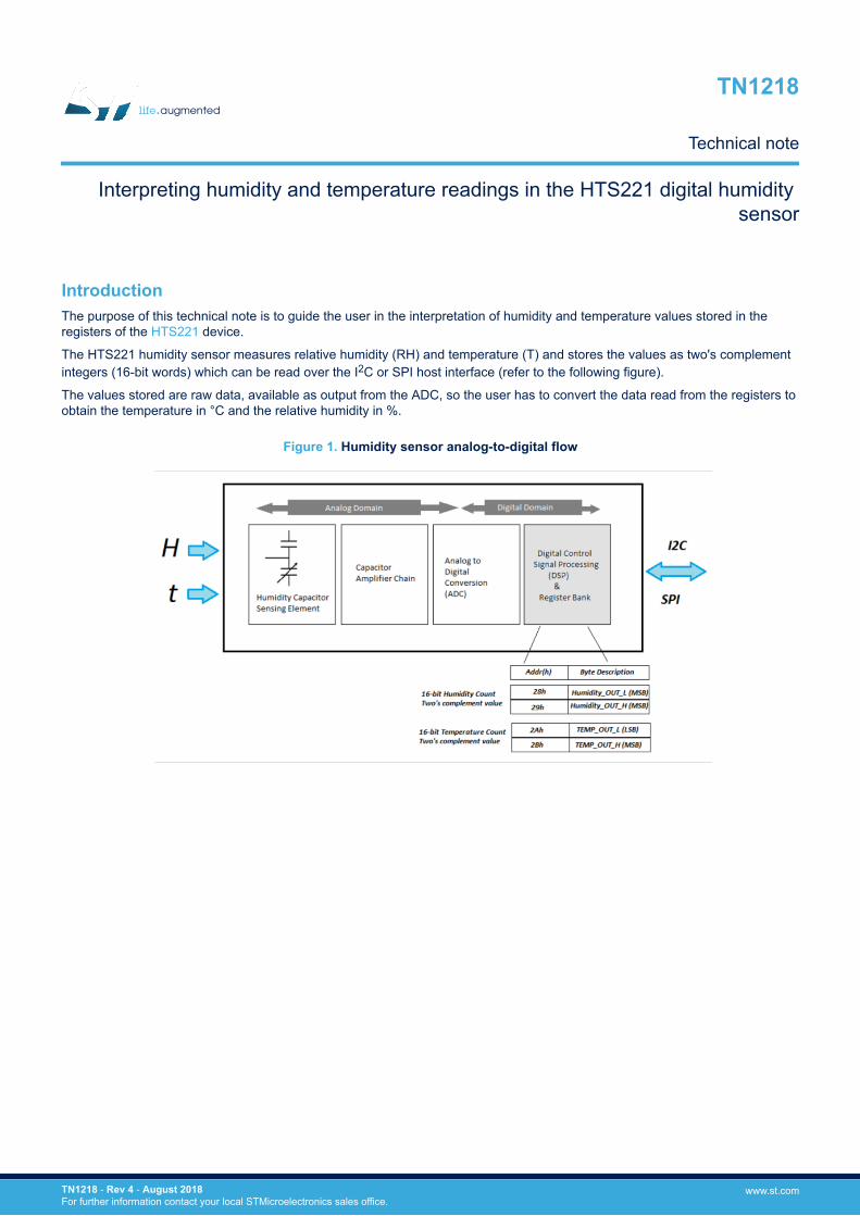
IntroductionThe purpose of this technical note is to guide the user in the interpretation of humidity and temperature values stored in theregisters of the HTS221 device.
The HTS221 humidity sensor measures relative humidity (RH) and temperature (T) and stores the values as two's complementintegers (16-bit words) which can be read over the I2C or SPI host interface (refer to the following figure).
The values stored are raw data, available as output from the ADC, so the user has to convert the data read from the registers toobtain the temperature in °C and the relative humidity in %.
Figure 1. Humidity sensor analog-to-digital flow
Interpreting humidity and temperature readings in the HTS221 digital humidity sensor
TN1218
Technical note
TN1218 - Rev 4 - August 2018For further information contact your local STMicroelectronics sales office.
www.st.com
1 How to obtain the relative humidity value (%RH)
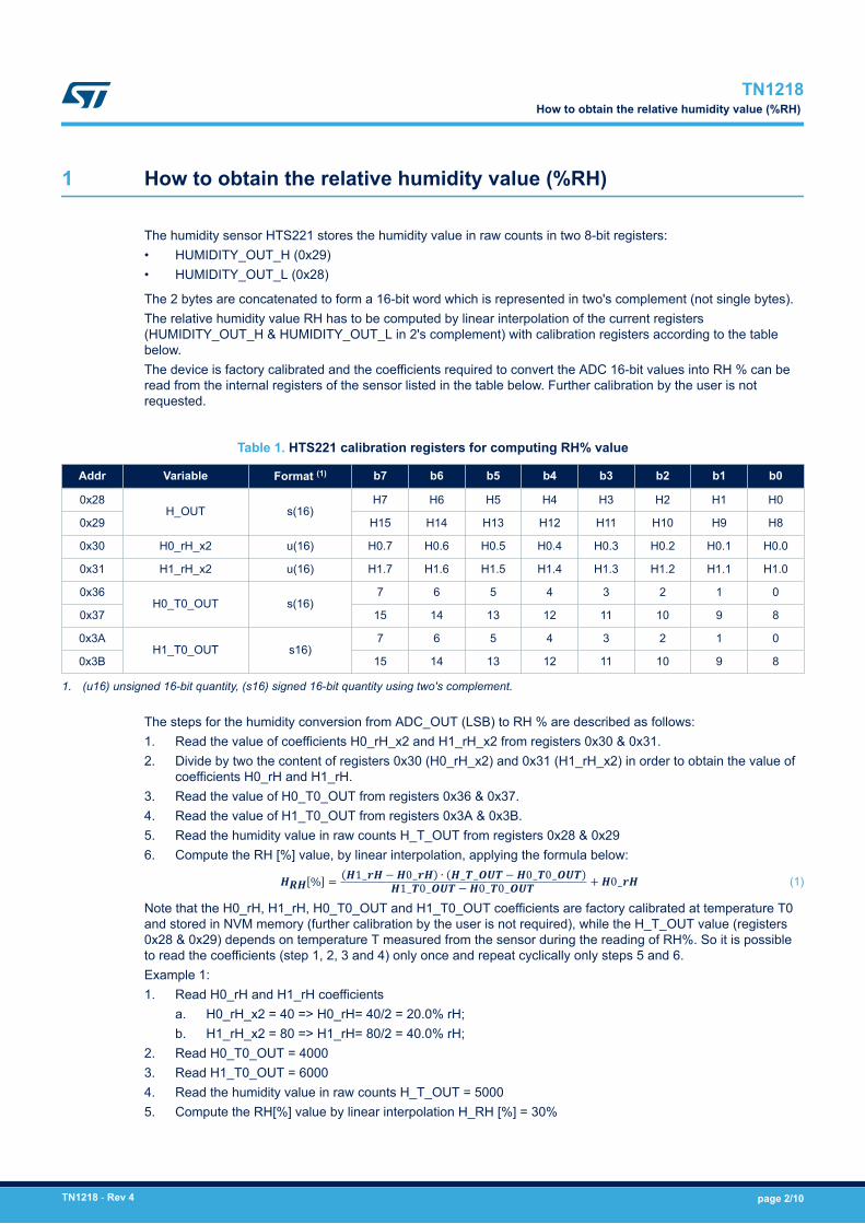
The humidity sensor HTS221 stores the humidity value in raw counts in two 8-bit registers:• HUMIDITY_OUT_H (0x29)• HUMIDITY_OUT_L (0x28)
The 2 bytes are concatenated to form a 16-bit word which is represented in two's complement (not single bytes).The relative humidity value RH has to be computed by linear interpolation of the current registers(HUMIDITY_OUT_H & HUMIDITY_OUT_L in 2's complement) with calibration registers according to the tablebelow.The device is factory calibrated and the coefficients required to convert the ADC 16-bit values into RH % can beread from the internal registers of the sensor listed in the table below. Further calibration by the user is notrequested.
Table 1. HTS221 calibration registers for computing RH% value
Addr Variable Format (1) b7 b6 b5 b4 b3 b2 b1 b0
0x28H_OUT s(16)
H7 H6 H5 H4 H3 H2 H1 H0
0x29 H15 H14 H13 H12 H11 H10 H9 H8
0x30 H0_rH_x2 u(16) H0.7 H0.6 H0.5 H0.4 H0.3 H0.2 H0.1 H0.0
0x31 H1_rH_x2 u(16) H1.7 H1.6 H1.5 H1.4 H1.3 H1.2 H1.1 H1.0
0x36H0_T0_OUT s(16)
7 6 5 4 3 2 1 0
0x37 15 14 13 12 11 10 9 8
0x3AH1_T0_OUT s16)
7 6 5 4 3 2 1 0
0x3B 15 14 13 12 11 10 9 8
1. (u16) unsigned 16-bit quantity, (s16) signed 16-bit quantity using two's complement.
The steps for the humidity conversion from ADC_OUT (LSB) to RH % are described as follows:1. Read the value of coefficients H0_rH_x2 and H1_rH_x2 from registers 0x30 & 0x31.2. Divide by two the content of registers 0x30 (H0_rH_x2) and 0x31 (H1_rH_x2) in order to obtain the value of
coefficients H0_rH and H1_rH.3. Read the value of H0_T0_OUT from registers 0x36 & 0x37.4. Read the value of H1_T0_OUT from registers 0x3A & 0x3B.5. Read the humidity value in raw counts H_T_OUT from registers 0x28 & 0x296. Compute the RH [%] value, by linear interpolation, applying the formula below:HRH % = H1_rH −H0_rH ∙ H_T_OUT −H0_T0_OUTH1_T0_OUT −H0_T0_OUT +H0_rH (1)
Note that the H0_rH, H1_rH, H0_T0_OUT and H1_T0_OUT coefficients are factory calibrated at temperature T0and stored in NVM memory (further calibration by the user is not required), while the H_T_OUT value (registers0x28 & 0x29) depends on temperature T measured from the sensor during the reading of RH%. So it is possibleto read the coefficients (step 1, 2, 3 and 4) only once and repeat cyclically only steps 5 and 6.Example 1:1. Read H0_rH and H1_rH coefficients
a. H0_rH_x2 = 40 => H0_rH= 40/2 = 20.0% rH;b. H1_rH_x2 = 80 => H1_rH= 80/2 = 40.0% rH;
2. Read H0_T0_OUT = 40003. Read H1_T0_OUT = 60004. Read the humidity value in raw counts H_T_OUT = 50005. Compute the RH[%] value by linear interpolation H_RH [%] = 30%
TN1218How to obtain the relative humidity value (%RH)
TN1218 - Rev 4 page 2/10
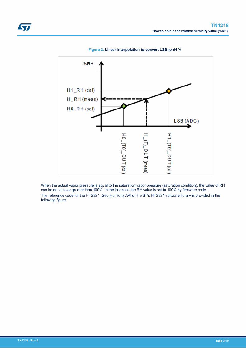
Figure 2. Linear interpolation to convert LSB to rH %
When the actual vapor pressure is equal to the saturation vapor pressure (saturation condition), the value of RHcan be equal to or greater than 100%. In the last case the RH value is set to 100% by firmware code.The reference code for the HTS221_Get_Humidity API of the ST's HTS221 software library is provided in thefollowing figure.
TN1218How to obtain the relative humidity value (%RH)
TN1218 - Rev 4 page 3/10
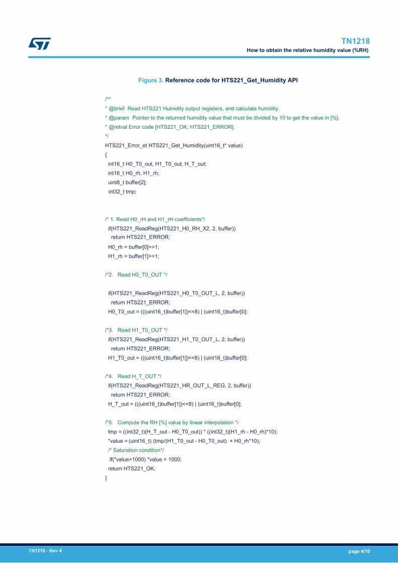
Figure 3. Reference code for HTS221_Get_Humidity API
/**
* @brief Read HTS221 Humidity output registers, and calculate humidity.
* @param Pointer to the returned humidity value that must be divided by 10 to get the value in [%].
* @retval Error code [HTS221_OK, HTS221_ERROR].
*/
HTS221_Error_et HTS221_Get_Humidity(uint16_t* value)
{
int16_t H0_T0_out, H1_T0_out, H_T_out;
int16_t H0_rh, H1_rh;
uint8_t buffer[2];
int32_t tmp;
/* 1. Read H0_rH and H1_rH coefficients*/
if(HTS221_ReadReg(HTS221_H0_RH_X2, 2, buffer))
H0_rh = buffer[0]>>1;
H1_rh = buffer[1]>>1;
/*2. Read H0_T0_OUT */
if(HTS221_ReadReg(HTS221_H0_T0_OUT_L, 2, buffer))
return HTS221_ERROR;
H0_T0_out = (((uint16_t)buffer[1])<<8) | (uint16_t)buffer[0];
/*3. Read H1_T0_OUT */
if(HTS221_ReadReg(HTS221_H1_T0_OUT_L, 2, buffer))
return HTS221_ERROR;
H1_T0_out = (((uint16_t)buffer[1])<<8) | (uint16_t)buffer[0];
/*4. Read H_T_OUT */
if(HTS221_ReadReg(HTS221_HR_OUT_L_REG, 2, buffer))
return HTS221_ERROR;
H_T_out = (((uint16_t)buffer[1])<<8) | (uint16_t)buffer[0];
/*5. Compute the RH [%] value by linear interpolation */
tmp = ((int32_t)(H_T_out - H0_T0_out)) * ((int32_t)(H1_rh - H0_rh)*10);
*value = (tmp/(H1_T0_out - H0_T0_out) + H0_rh*10);
/* Saturation condition*/
if(*value>1000) *value = 1000; return HTS221_OK;
}
(uint16_t)
return HTS221_ERROR;
TN1218How to obtain the relative humidity value (%RH)
TN1218 - Rev 4 page 4/10
2 How to obtain the temperature value in degree Celsius (°C)
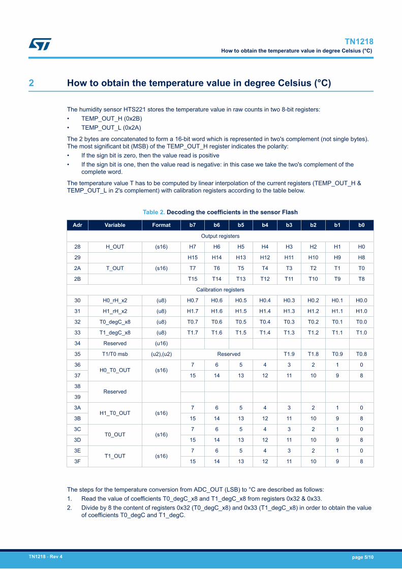
The humidity sensor HTS221 stores the temperature value in raw counts in two 8-bit registers:• TEMP_OUT_H (0x2B)• TEMP_OUT_L (0x2A)
The 2 bytes are concatenated to form a 16-bit word which is represented in two's complement (not single bytes).The most significant bit (MSB) of the TEMP_OUT_H register indicates the polarity:• If the sign bit is zero, then the value read is positive• If the sign bit is one, then the value read is negative: in this case we take the two's complement of the
complete word.
The temperature value T has to be computed by linear interpolation of the current registers (TEMP_OUT_H &TEMP_OUT_L in 2's complement) with calibration registers according to the table below.
Table 2. Decoding the coefficients in the sensor Flash
Adr Variable Format b7 b6 b5 b4 b3 b2 b1 b0
Output registers
28 H_OUT (s16) H7 H6 H5 H4 H3 H2 H1 H0
29 H15 H14 H13 H12 H11 H10 H9 H8
2A T_OUT (s16) T7 T6 T5 T4 T3 T2 T1 T0
2B T15 T14 T13 T12 T11 T10 T9 T8
Calibration registers
30 H0_rH_x2 (u8) H0.7 H0.6 H0.5 H0.4 H0.3 H0.2 H0.1 H0.0
31 H1_rH_x2 (u8) H1.7 H1.6 H1.5 H1.4 H1.3 H1.2 H1.1 H1.0
32 T0_degC_x8 (u8) T0.7 T0.6 T0.5 T0.4 T0.3 T0.2 T0.1 T0.0
33 T1_degC_x8 (u8) T1.7 T1.6 T1.5 T1.4 T1.3 T1.2 T1.1 T1.0
34 Reserved (u16)
35 T1/T0 msb (u2),(u2) Reserved T1.9 T1.8 T0.9 T0.8
36H0_T0_OUT (s16)
7 6 5 4 3 2 1 0
37 15 14 13 12 11 10 9 8
38Reserved
39
3AH1_T0_OUT (s16)
7 6 5 4 3 2 1 0
3B 15 14 13 12 11 10 9 8
3CT0_OUT (s16)
7 6 5 4 3 2 1 0
3D 15 14 13 12 11 10 9 8
3ET1_OUT (s16)
7 6 5 4 3 2 1 0
3F 15 14 13 12 11 10 9 8
The steps for the temperature conversion from ADC_OUT (LSB) to °C are described as follows:1. Read the value of coefficients T0_degC_x8 and T1_degC_x8 from registers 0x32 & 0x33.2. Divide by 8 the content of registers 0x32 (T0_degC_x8) and 0x33 (T1_degC_x8) in order to obtain the value
of coefficients T0_degC and T1_degC.
TN1218How to obtain the temperature value in degree Celsius (°C)
TN1218 - Rev 4 page 5/10
3. Read the MSB bits of T1_degC (T1.9 and T1.8 bit) and T0_degC (T0.9 and T0.8 bit) from register 0x35 tocompute T0_DegC and T1_DegC.
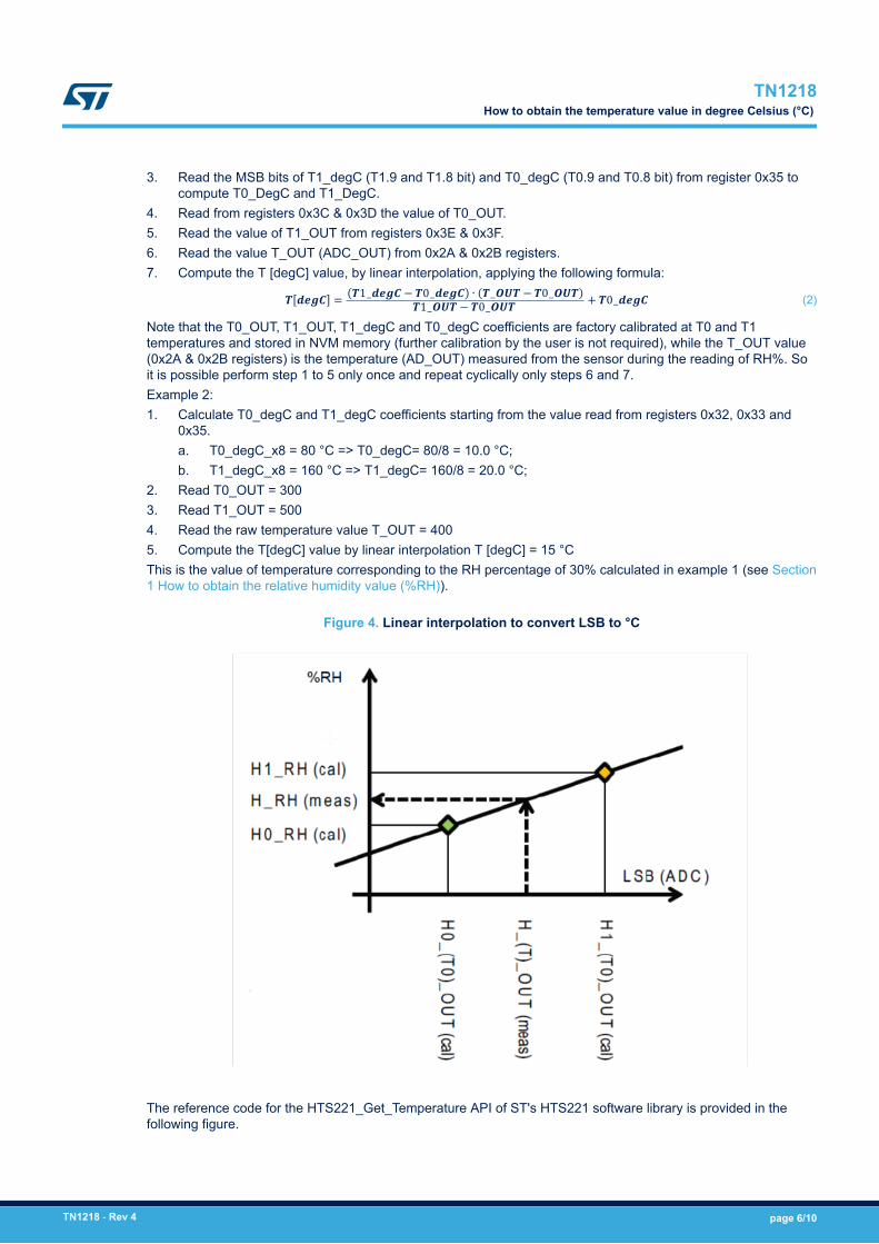
4. Read from registers 0x3C & 0x3D the value of T0_OUT.5. Read the value of T1_OUT from registers 0x3E & 0x3F.6. Read the value T_OUT (ADC_OUT) from 0x2A & 0x2B registers.7. Compute the T [degC] value, by linear interpolation, applying the following formula:T degC = T1_degC − T0_degC ∙ T_OUT − T0_OUTT1_OUT − T0_OUT + T0_degC (2)
Note that the T0_OUT, T1_OUT, T1_degC and T0_degC coefficients are factory calibrated at T0 and T1temperatures and stored in NVM memory (further calibration by the user is not required), while the T_OUT value(0x2A & 0x2B registers) is the temperature (AD_OUT) measured from the sensor during the reading of RH%. Soit is possible perform step 1 to 5 only once and repeat cyclically only steps 6 and 7.Example 2:1. Calculate T0_degC and T1_degC coefficients starting from the value read from registers 0x32, 0x33 and
0x35.a. T0_degC_x8 = 80 °C => T0_degC= 80/8 = 10.0 °C;b. T1_degC_x8 = 160 °C => T1_degC= 160/8 = 20.0 °C;
2. Read T0_OUT = 3003. Read T1_OUT = 5004. Read the raw temperature value T_OUT = 4005. Compute the T[degC] value by linear interpolation T [degC] = 15 °CThis is the value of temperature corresponding to the RH percentage of 30% calculated in example 1 (see Section1 How to obtain the relative humidity value (%RH)).
Figure 4. Linear interpolation to convert LSB to °C
The reference code for the HTS221_Get_Temperature API of ST's HTS221 software library is provided in thefollowing figure.
TN1218How to obtain the temperature value in degree Celsius (°C)
TN1218 - Rev 4 page 6/10
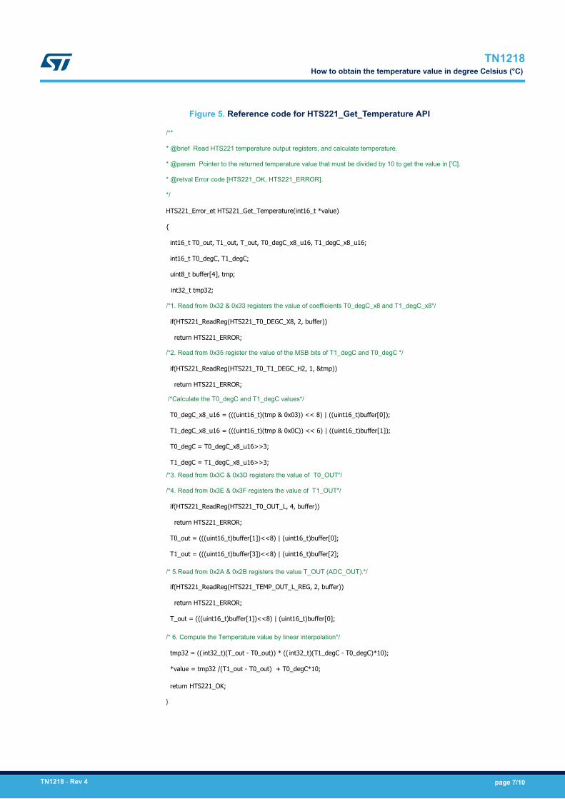
Figure 5. Reference code for HTS221_Get_Temperature API
/**
* @brief Read HTS221 temperature output registers, and calculate temperature.
* @param Pointer to the returned temperature value that must be divided by 10 to get the value in ['C].
* @retval Error code [HTS221_OK, HTS221_ERROR].
*/
HTS221_Error_et HTS221_Get_Temperature(int16_t *value)
{
int16_t T0_out, T1_out, T_out, T0_degC_x8_u16, T1_degC_x8_u16;
int16_t T0_degC, T1_degC;
uint8_t buffer[4], tmp;
int32_t tmp32;
/*1. Read from 0x32 & 0x33 registers the value of coefficients T0_degC_x8 and T1_degC_x8*/
if(HTS221_ReadReg(HTS221_T0_DEGC_X8, 2, buffer))
return HTS221_ERROR;
/*2. Read from 0x35 register the value of the MSB bits of T1_degC and T0_degC */
if(HTS221_ReadReg(HTS221_T0_T1_DEGC_H2, 1, &tmp))
return HTS221_ERROR;
/*Calculate the T0_degC and T1_degC values*/
T0_degC_x8_u16 = (((uint16_t)(tmp & 0x03)) << 8) | ((uint16_t)buffer[0]);
T1_degC_x8_u16 = (((uint16_t)(tmp & 0x0C)) << 6) | ((uint16_t)buffer[1]);
T0_degC = T0_degC_x8_u16>>3;
T1_degC = T1_degC_x8_u16>>3;
/*3. Read from 0x3C & 0x3D registers the value of T0_OUT*/
/*4. Read from 0x3E & 0x3F registers the value of T1_OUT*/
if(HTS221_ReadReg(HTS221_T0_OUT_L, 4, buffer))
return HTS221_ERROR;
T0_out = (((uint16_t)buffer[1])<<8) | (uint16_t)buffer[0];
T1_out = (((uint16_t)buffer[3])<<8) | (uint16_t)buffer[2];
/* 5.Read from 0x2A & 0x2B registers the value T_OUT (ADC_OUT).*/
if(HTS221_ReadReg(HTS221_TEMP_OUT_L_REG, 2, buffer))
return HTS221_ERROR;
T_out = (((uint16_t)buffer[1])<<8) | (uint16_t)buffer[0];
/* 6. Compute the Temperature value by linear interpolation*/
tmp32 = (( int32_t)(T_out - T0_out)) * (( int32_t)(T1_degC - T0_degC)*10);
*value = tmp32 /(T1_out - T0_out) + T0_degC*10;
return HTS221_OK;
}
TN1218How to obtain the temperature value in degree Celsius (°C)
TN1218 - Rev 4 page 7/10
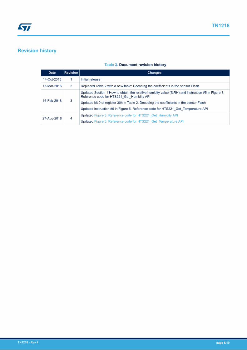
Revision history
Table 3. Document revision history
Date Revision Changes
14-Oct-2015 1 Initial release
15-Mar-2016 2 Replaced Table 2 with a new table: Decoding the coefficients in the sensor Flash
16-Feb-2018 3
Updated Section 1 How to obtain the relative humidity value (%RH) and instruction #5 in Figure 3.Reference code for HTS221_Get_Humidity API
Updated bit 0 of register 30h in Table 2. Decoding the coefficients in the sensor Flash
Updated instruction #6 in Figure 5. Reference code for HTS221_Get_Temperature API
27-Aug-2018 4Updated Figure 3. Reference code for HTS221_Get_Humidity API
Updated Figure 5. Reference code for HTS221_Get_Temperature API
TN1218
TN1218 - Rev 4 page 8/10
Contents
1 How to obtain the relative humidity value (%RH) . . . . . . . . . . . . . . . . . . . . . . . . . . . . . . . . . . .2
2 How to obtain the temperature value in degree Celsius (°C) . . . . . . . . . . . . . . . . . . . . . . . .5
Revision history . . . . . . . . . . . . . . . . . . . . . . . . . . . . . . . . . . . . . . . . . . . . . . . . . . . . . . . . . . . . . . . . . . . . . . . .8
TN1218Contents
TN1218 - Rev 4 page 9/10

IMPORTANT NOTICE – PLEASE READ CAREFULLY
STMicroelectronics NV and its subsidiaries (“ST”) reserve the right to make changes, corrections, enhancements, modifications, and improvements to STproducts and/or to this document at any time without notice. Purchasers should obtain the latest relevant information on ST products before placing orders. STproducts are sold pursuant to ST’s terms and conditions of sale in place at the time of order acknowledgement.
Purchasers are solely responsible for the choice, selection, and use of ST products and ST assumes no liability for application assistance or the design ofPurchasers’ products.
No license, express or implied, to any intellectual property right is granted by ST herein.
Resale of ST products with provisions different from the information set forth herein shall void any warranty granted by ST for such product.
ST and the ST logo are trademarks of ST. All other product or service names are the property of their respective owners.
Information in this document supersedes and replaces information previously supplied in any prior versions of this document.
© 2018 STMicroelectronics – All rights reserved
TN1218
TN1218 - Rev 4 page 10/10