Embed Size (px)
Citation preview

Technical Note N-1452
HIGH VOLTAGE CABLE SPLICING ANDCABLE TERMINATION TECHNIQUES
By
David E. Weems
August 1976
Sponsored by cNAVAL FACILITIES ENGINEERING COMMAND
Approved for public release; distribution unlimited.
CIVIL ENGINEERING LABORATORYNaval Construction Battalion CenterPort Hueneme, California 93043

UnclassifiedSECURITY CLASSIFICATION OF TIS PAGE 014the Data PnlcrdJ
RFAD INSTRUCTIONSREPORT DOCUMENTATION PAGE BEFORE COMPL ETING FORM
IREPORT NUMBER 2GOVT ACCESSIO3N NO' CIPIENTS NUMBER
TN-1452 -7 DN587021 A 4
4. TITLE fond S~bIc PF 0D CO0V ER E
HIGH VOLTAGE WALE SPLICING AND _CABLE/ Final, iii 374- Dec 1975,_TERMINATION JECHNIQUES. Cf PERFORMING ORG. REPORT NUMBER
7, AT"OR*, 8 CONTRACT OR GRANT NUMBERf.)
9. PRFOMINGORGNIZTIONNAM ANDADDESS10. PROGRAM ELEMENT PROJECT, TASKS. PRFOMINGORGNIZTIONNAM ANDADDESSAREA & WORK UNIT NUMBERS
CIVIL ENGINEERING LABORATORY 76NYF3540.O03
I4 M ONTRORING AGENCY NAME &N ADRESS ~fco r0C~rI 4Ofo SSCRT LS.(l~. eol
CF4 -TA/- S. DECLASSIFICATION DOWNGRADING
1ISTIUTO STATMEN (o th Reort
18 SUPPLEMENTARY NOTESj
IN KEY WORDS (C-oni,.. - I- - S. id. It ,o.....v -nd idenllfy l6c block -b-).~
Cables; electric cables; underground; high voltage; electric power; distribution; splicing
0.Ar4 AT (COPtf'.*- Sooo ide ift y.-d idrit,fy by block .- ~be,)Te splicing and termination of underground electrical distribution cable requires
that the integrity of cable conductor and insulation be maintained throughout its length.A large number of commercial cable splice and termination kits are available which areclaimed to fulfill these requirements. The Civil Engineering Laboratory (CEL) wasrequested to investigate the suitability of these kits for use at Naval shore facilities. ofspecial interest wcre the slip-on cable splice and cable termination for solid dielectricinsulated cable. These slip-on devices proved to be the easiest and fintest to instal with
DD OR 1473 EDITION OF I NOV819 IS OBSOLETEUnaife
SECURIITY CLASSIFICATION Of TIS PAGE f*Ilf D.M qntford)

UnclassifiedSECURITY CLASSIFICATION OF THIS PAGE(Who Dotl Enled)
20. Continued
good reproducibility, and the electrical characteristics were as good as, or better than,the other types of cable splice and cable termination kits tested.
Library card
Civil Engineering Laboratory
HIGH VOLTAGE CABLE SPLICING AND CABLETERMINATION TECHNIQUES (final), by David E. WeemsTN-1452 20 pp illus August 1976 Unclassified
1. Cables 2. high voltage I. YF53.534.006.01.037
The splicing and termination of underground electrical distribution cable requires that theintegrity of cable conductor and insulation be maintained throughout its length. A large numberof commercial cable splice and termination kits are available which are claimed to fulfill theserequirements. The Civil Engineering Laboratory (CEL) was requested to investigate thesuitability of these kits for use at Naval shore facilities. Of special interest were the slip-oncable splice and cable termination for solid dielectric insulated cable. These slip-on devicesproved to be the easiest and fastest to install with good reproducibility, and the electricalcharacteristics were as good as, or better than, the other types of cable splice and cabletermination kits tested.
- -- ---- ---------------- -- -- -- --
UnclassifiedSECURITY CLASSIFICATION OF THIS PAGEfWhen Dole FnIe-d)

CONTENTS
Page
INTRODUCTION............................1
BACKGROUND.............................1
INDUSTRY SURVEY............................2
Cables Used for High Voltage Underground Distribution . .. 2
Splicing High Voltage Cable .................. 3
TEST MATERIALS AND ASSEMBLY......................5
Splice Kits...........................5
Termination Kits........................6
High Voltage Cable.......................6
Assembly.............................6
Testing Equipment.......................8
TEST PROCEDURE............................8
TEST RESULTS...........................10
CONCLUSIONS............................15
RECOMMENDATIONS...........................15
APPENDIX
Discussion of High Voltage Cable Termination .. ....... 16
8110
......................... ......... ......
By.................. ......... ......'Or
cDES'NAj
L

INTRODUCTION
Electrical distribution systems at Naval shore facilities consistof long lengths of conductors operating at voltages in excess of 600volts. Because of the length of the conductors required, it is necessaryto join or splice conductors together. In the case of overhead transmis-sion lines it is a simple task to install the conductors, since insulationof the conductors is not required. With underground distributionsystems, splicing conductors is complicated by the requirement forinsulation around the conductor to prevent electrical contact with theearth. When the conductors are spliced the insulation and shields mustalso be joined.
To splice electrical power cable, insulation material is wrappedaround the joined conductor. With the development of solid dielectricinsulated cables came the premolded or 'slip-on'' splice kit, a largenumber of which are commercially available. The manufacturers claimthat the kits provide the same or improved splice quality when comparedto the hand-wrapped type, with less training and experience required ofthe installation personnel.
The objective of testing these splice kits is to evaluate theirelectrical properties, safety, durability, reproducibility, ease, andtime and cost of installation.
BACKGROUND
Electrical power is normally distributed by copper or aluminumconductors. In overhead distribution systems where conductor separationfrom ground and each other can be maintained, insulation is not necessary.This is not the case where the electrical distribution system is under-ground or is accessible to personnel.
Oil-impregnated paper, varnish cambric, or a solid dielectricmaterial is used to insulate high voltage power cable. The first twotypes of insulation require a lead sheath to protect the insulation fromthe environment. Because of the lead sheath, splicing and terminationof cables with these types of insulation must be performed by a highlyskilled cable splicer.
The solid dielectric insulated cables have a rubber or rubber-likematerial covering the conductor to provide both insulation and environ-mental protection. Splicing of this type of cable requires use ofinsulation material to build up the insulation over the joined conductors.The finished result must be electrically equivalent to the originalcable insulation. Several different types of termination and splicekits are available to simplify this procedure. They include: kits thatprovide tape and directions, kits that have precut tape, and premoldedslip-on cable splices.

Naval shore facilities have experienced operational failures withhigh voltage cable splices now used in underground electrical powerdistribution systems. These failures were caused in most cases bymoisture penetration in underground distribution systems subject to highwater tables or flooding from surface drainage.
As a result of these failures, the Civil Engineering Laboratory(CEL) was requested to evaluate the state-of-the-art high voltage cablesplicing and termination techniques and materials.
INDUSTRY SURVEY
The industry was surveyed to determine the types of electricalpower cables used for underground electrical distribution and the methodof splicing each type. The survey included contacting four of theelectrical power cable manufacturers, six of the cable splice materialmanufacturers, three electrical utility companies, and several Navalshore facilities.
Cables Used for High Voltage Underground Distribution
High voltage cables currently manufactured for underground distribu-tion fall into one of two types: paper-insulated lead-covered (PILC)cable and solid dielectric insulated cable.
The PILC cable consists of a copper conductor insulated with oil-impregnated paper. Due to the presence of the oil and the deteriorativeeffect of water on the insulation properties, a lead covering is addedover the insulation. This lead covering holds the oil in and protectsthe insulation from the environment.
PILC cable is the oldest type of electrical power cable. Thepopularity of this type of cable has dropped since the 1940's when soliddielectric insulated cable was introduced. Electrical utility companies,such as Southern California Edison, are currently installing PILC cableonly in locations where space limitations require replacement of existingcable with PILC cable instead of solid dielectric insulated cable.
The Navy still uses a large amount of PILC cable. For example,Mare Island Naval Shipyard's underground electrical distribution systemis approximately 90% PILC cable.
The second type of high voltage underground cable is the soliddielectric insulated cable. This type of cable is normally constructedwith five parts: the conductor, the conductor shield, the insulation,the insulation shield, and the outer conductor (Figure 1).
The insulation material is a synthetic insulating rubber producedfrom oil. Two of the most popular solid dielectric insulations currentlyused are high-molecular-weight polyethylene (EP) and cross-linked poly-ethylene (XLPE). The EP insulation is rated for 750 C a maximum temperature,and the XLPE insulation is rated for 900C maximum temperature. Theseinsulation materials provide the conductor with protection from theenvironment,' thereby eliminating requirement for a lead covering. Anouter jacket is added on many cables to provide environmental protectionfor the outer conductor.
2

The conductor used in the past for electrical power cables has beencopper; however, a large number of the cables currently being installedhave lower cost aluminum conductors. The use of aluminum instead ofcopper can reduce the material cost up to 50%.
The cost of installing PILC with copper conductors is compared tothe cost of installing XLPE cable with aluminum conductors in Table 1.
The manufacturers design the shields on solid dielectric insulatedcables to confine the electric field to the insulation between theshields. The shields are a semiconducting material; therefore, theymaintain a constant potential at the boundaries of the insulations.During a fault condition the fault current is carried to earth ground bythe outer conductor.
Splicing High Voltage Cable
Splicing of high voltage electrical cables is required to maintainthe electrical continuity of the conductor and shields and to maintainthe insulation levels of the two electrical cables joined together.These cables are spliced by joining the two conductors: insulation isbuilt up over the exposed conductor to provide insulation propertiessimilar to those of the cable insulation: the cable shields are thenjoined to confine the electric field to the insulation.
In the case of PILC cable the built-up insulation material is anoil-impregnated paper. Due to presence of the oil a lead sleeve must beadded over the PILC cable splice to hold the oil in and protect theinsulation from the environment. This lead sleeve must be properlyjoined to the lead covering on both of the cables being spliced togetherto provide this environmental protection. The entire PILC cable splicingprocedure requires not only a highly qualified cable splicer but a greatdeal of time.
Solid dielectric insulated cables are spliced in one of two ways:handwrapping with insulation tape or slipping a premolded cable spliceover the joined conductors.
Handwrapping a splice by a highly skilled cable splicer requiresalmost as much time to complete as it does to splice PILC cable.The cable splicer must select the proper tape for each level of thesplice, build up the tape to the proper dimensions for the cablebeing spliced, and insure that no air voids or contaminations arepresent in the final splice.
The premolded or slip-on cable splices for solid dielectric insulatedcables were introduced in the 1950's. This type of cable splice isdesigned and manufactured at the factory to provide the insulationlevels and electric field control required for a given size of electricalcable. The manufacturer is therefore able to test the insulation leveland electric field control prior to shipping the unit. This type ofcable splice can be installed in less than half the time required for ahandwrapped cable splice, as shown in Table 2. Preparing the cable andjoining the conductor are the same for either the premolded or the
3

handwrapped splices. However, once the cable is prepared and the conduc-
tors are joined, the premolded splice is slipped over the exposed conduc-
tors in less than 5 minutes. Therefore, the cable splicer requires much
less experience to install a premolded cable splice than to install the
other type of cable splice. This is important where cable splices arenot installed frequently.
The cost, as shown in Table 2, of premolded cable splice materialis much higher than material for the handwrapped tape of PILC splice,but this difference is offset by labor costs.
Premolded cable splices have proved to be highly reliable in the
electrical utility company installations. Southern California Edison
has installed approximately 217,000 premolded rubber components between
May 1967 and December 1974 on polyethylene insulated cable. Of these
217,000 installations there have been 114 failures of 0.052% failure
rate. Of these failures 103 were due to poor workmanship or incorrectapplication, one to a manufacturing defect, and 10 to unknown causes(insufficient material to determine cause).
Figure 1. Cross section of cross-linked polyethylene-insulatedunderground cable.
4

Table 1. Cost of Cable Installation per 100 Feet of Length
onductor CCost ofCable (kV) Conductor Material (manhr)(Volag SMize Material Cs) Lmabor)
(MCM)
3-1/C PILC 5 500 Copper 888 7.2
3/C PILC 5 500 Copper 844 3.7
3-1/C XLPE 5 750 Aluminum 301 3.5
3-1/C PILC 17 500 Copper 1,014 7.2
3/C PILC 17 500 Aluminum 1,032 3.7
3-1/C XLPE 17 750 Aluminum 437 3.5
Table 2. Splice Installation Costs
Splice Conductor No. of Labor MaterialRating SiC Conductors Insulation Splice Type (man-r) Cost(WV (MCM)($
5 750 1 XLPE Tape 7.0 30
750 1 XLPE Premolded 2.9 78
500 1 PILC PILC 4.7 19
500 3 PILC PILC 13.5 43
17 750 1 XLPE Tape 7.0 30
750 1 XLPE Premolded 2.0 99
500 1 PILC PILC 7.0 30
500 3 PILC PILC 17.0 66
TEST MATERIALS AND ASSEMBLY
Splice Kits
The following cable splice kits were procured for testing:
Voltage Current
Manufacturer Part No. (kV) (amperes)
Elastimold 25S 15 200
Elastimold K25S 25 200Elastimold 750-L2 35 600Elastimold 650S 15 600ITT* Blackburn S-GAB-AM 15 400
*International Telephone and Telegraph.
5

Voltage CurrentManufacturer Part No. (kV) (amperes)
ITT Blackburn SC-GH-AL 25 400
ITT Blackburn S65 15 600
G.E. A1791717917 25 200
G.E. SS-15-B 15 200
3M 5718 15 200
3M 5402 15 150
Termination Kits
The following cable termination kits were procured for testing:
VoltageManufacturer Part No. (kV)
Elastimold 35MSC 35
ITT Blackburn SKC 25
ITT Blackburn SKD 35
Raychem HVT-0-B-2 15
G.E. 3T-15-B 15
High Voltage Cable
The high voltage cable used for the testing was aluminum-conductor,cross-linked, polyethylene-insulated cable (Figure 1). This cable has aconductor shield and a 30-mil insulation shield of conducting polyethylene.The cable has concentric copper outer conductors. The thickness of thecross-linked polyethylene insulation is: 175 mils for 15 kV cable, 260mils for 25 kV cable, and 345 mils for 35 kV cable.
Assembly
Two 5-foot lengths of high voltage cable were cut and prepared, andcable splices were installed in accordance with the manufacturers'recommendations. The shields on the remaining ends of the cable wereterminated wiLh the appropriately sized stress-relief cones in accordancewith the manufacturers' recommendations.
Figure 2 shows the resulting test items after assembly. Table 3lists the types of cable splices, the type of stress-relief cones, andthe size of the high voltage cable for each of the test items.
General Electric.
Minnesota Mining and Manufacturing.
6
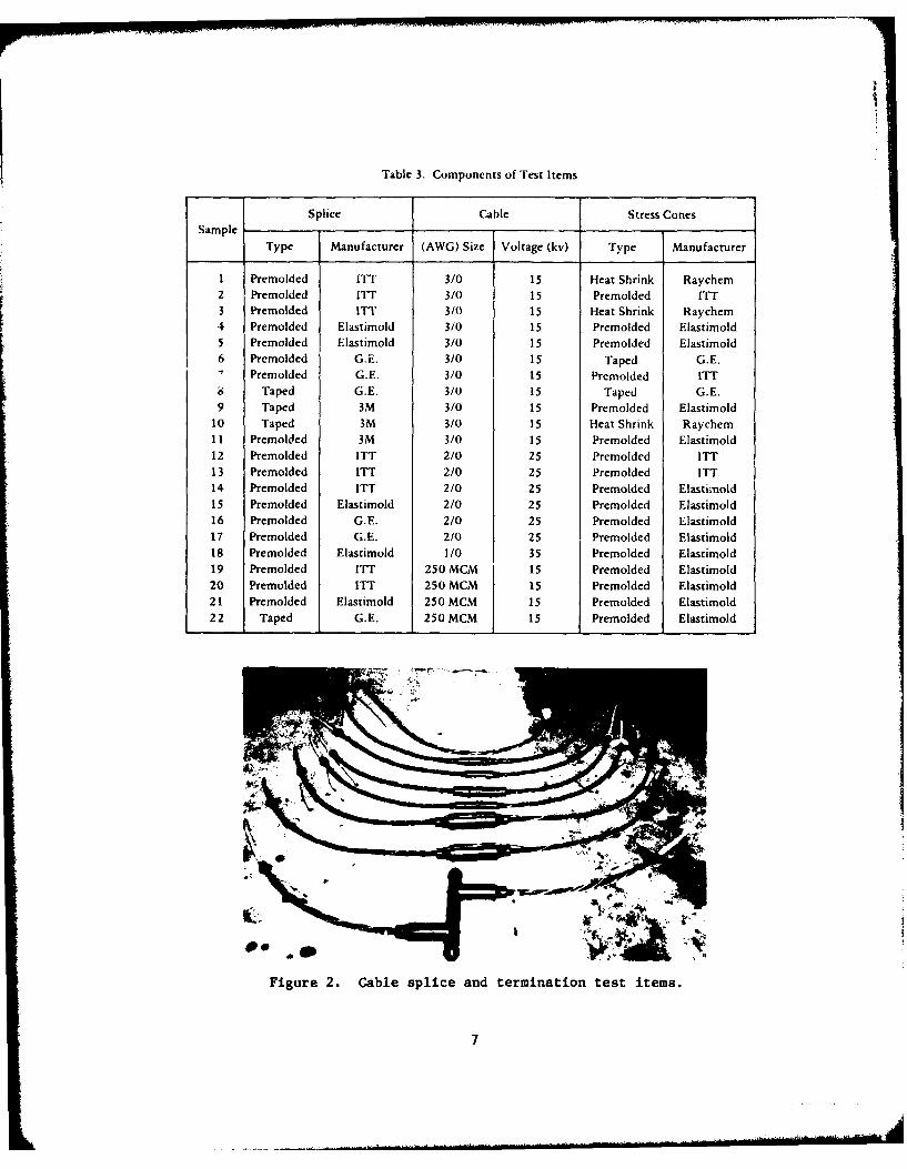
Table 3. Components of Trest items
Splice Cable Stress ConesSample
Type Manufacturer (AWG) Size Voltage (kv) Type Manu factu rer
1 Premolded ITT 3/0 15 Heat Shrink Raychem2 Premolded ITT 3/0 15 Premolded ITT3 Premolded ITT 3/0 15 Heat Shrink Raychem4 Premolded Elasrimold 3/0 15 Premolded Elastimold5 Premolded Elastimold 3/0 15 Premolded Elastimold6 Premolded G.E. 3/0 15 Taped G.E.
Premolded G.E. 3/0 15 Premolded ITTi ~Taped G.E. 3/0 15 Taped G.E.
9 Taped 3M 3/0 15 Premolded Elastimold10 Taped 3M 3/0 15 Heat Shrink Raychem11 Premolded 3M 3/0 15 Premolded Elastimold12 Premolded ITT 2/0 25 Premolded ITT13 Premolded ITT 2/0 25 Premolded ITT14 Premolded ITT 2/0 25 Premolded Elastimold15 Premolded Elastimold 2/0 25 Premolded Elastimold16 Premolded G.E. 2/0 25 Premolded Elastimold17 Premolded G.E. 2/0 25 Premolded Elastimold18 Premolded Elastimold 1/0 35 Premolded Elastimold19 Premolded ITT 250 MCM 15 Premolded Elastimold20 Premolded ITT 250 MCM 15 Premolded Elastimold21 Premolded Elastimold 250 MCM 15 Premolded Elastimold22 Taped G.E. 250 MCM 15 Premolded Elastimold
Figure 2. Cable splice and termination test items.
7

Testing Equipment
1. The Hipotronics, Inc., Model 7150-60 AC dielectric/insulationtest equipment (Figure 3) was used to generate the adjustable highvoltage 60-Hertz power. This unit has the following specifications:
(a) Input: 440 volts AC, 60 Hz, 145 amperes, 60 kV amperes
(b) Output: 150 kV AC at 0.4 amperes75 kV AC at 0.8 amperes
(c) Distortion: Less than 5%
(d) Duty: 60 kV amperes for 1 hour50 kV amperes continuous
(e) Voltmeter: 0-37.5/75/150 kV AC scale ±2% accuracy
(f) Current Meter: 0-1.0 amperes scale ±2% accuracy
2. The Hipotronics, Inc., Model CDO-68-C corona detector was usedto measure the corona level.
3. The Multi-Amp Corporation, Model CB-150, circuit breaker testunit was used to generate the high current 60-Hertz power. This unithas the following specifications:
(a) Input: 208/220/480 volt, 60 Hertz, 15 kV amperes
(b) Output: 0-5,000 amperes at 0-3 volts0-2,500 amperes at 0-6 volts0-1,250 amperes at 0-12 volts
TEST PROCEDURES
Cable splices and terminations must provide at least the same levelof protection as the original cable. The following tests were performedto compare the electrical and environmental characteristics of the cablesplices and cable terminations to those specified by Insulated PowerCable Engineers Association (IPCEA) standard publications S-19-81 andS-66-524.*
The test items were connected to the dielectric/insulation testequipment (Figure 3). One end of the conductor was connected to thehigh voltage terminal, and the drain wire was grounded. The other endof the conductor was terminated in a toroid to eliminate corona producedby the sharp breaks in the conductor strands. The corona detector wasconnected to the high voltage terminal to monitor any high frequencyvoltage which would be caused by corona.
Insulated Power Cable Engineers Association. S-19-81 (Fifth Edition):Standard publication for rubber-insulated wire and cable. Belmont,MA, 1969.
Insulated Power Cable Engineers Association. S-66-524: Standardpublication for cross-linked, thermosetting, polyethylene-insulatedwire and cable. Belmont, MA, 1971.
8

AM1.. 1
Figure 3. Equipment for testing dielectric insulation items.
The voltage on the high voltage terminal was slowly increased untilcorona occurred on the test item. The voltage was then reduced untilthe corona stopped. The voltage between the conductor and the drain wire
of the test item was then recorded. This voltage is the corona extinctionvoltage.
The AC-withstand test was then performed. This consisted ofsubjecting the test item to a voltage of 35 kV for 15 kV test items, 42kV for 25 kV test items, and 50 kV for 35 kV test items. This highvoltage was maintained for a period of 1 minute.
At the end of the AC-withstand test the corona extinction voltagewas again measured to determine if the test item had suffered any unde-tected damage.
The environmental test consisted of placing the test items in atank of seawater (Figure 4). The conductors of each test item wereconnected in series and their insulation resistances were measured witha megger. A current equal to 140% of the current rating was suppliedthrough the conductors of the test items. The current was cycled on for75 minutes and off for 120 minutes, three times a day during workinghours for 2 weeks. In this test the cable splice was heated internallyand then allowed to cool down in seawater, approximating the fieldsituation where most heating is internally generated.
After the test items were subjected to the environmental test,their corona extinction voltage was determined, and they were againsubjected to the AC-withstand test.
9

TEST RESULTS
Table 4 gives the results of the laboratory testing of high voltagecable splices and termination.
All of the test items had corona extinction voltages higher thanthe operating voltage for which the items were designed.
All of the test items withstood the 1-minute application of highvoltage except test item 1, which failed at one of the stress-reliefcones. The failure, shown in Figure 5, was due to a puncture in theinsulation caused by the concentrated electric field around a small airpocket located between the stress-relief cone and the insulation.The Appendix discusses the elastic field and termination of high voltagecable.
After the current-cycling test, two items failed. Test item 19 hada corona extinction voltage well above the minimum requirements for the
voltage rating of the test item. During the AC-withstand test theinsulation under one of the stress-relief cones was punctured as shownin Figure 6. This failure was due to a small cut in the insulation andthe overheating of the insulation during the current-cycling test.
Table 4. Test Results
Corona Current-Cycling TestCion AC-Withstand Final Corona Final AC-
Sample Extinction Extinction WithstandVoltage (kV) Voltage (kV) Current NumberVoltage (amperes) of Cycles Voltage (kV) Voltage (kV)
1 11.0 Failurea
2 11.0 35 325 27 11.0 353 18.5 35 325 27 8.5 354 15.0 35 325 27 12.5 355 10.0 35 325 27 13.5 356 15.0 35 325 27 11.0 357 9.0 35 325 27 10.0 358 17.0 35 325 27 12.0 359 9.5 35 325 27 11.0 35
10 12.0 35 325 27 8.5 3511 9.5 35 325 27 8.5 3512 16.0 42 300 30 16.0 4213 20.5 42 300 30 25.5 4214 18.5 42 300 30 19.5 4215 17.5 42 300 30 18.5 4216 17.0 42 300 30 15.5 4217 19.5 42 300 39 18.5 4218 22.0 50 450 39 21.0 5019 11.5 35 450 39 13.0 Failurea
20 14.0 35 450 39 15.5 3521 20.0 35 450 39 15.0 3522 16.0 35 450 39 1.5
b 35
Falure occurred in the insulation under one of the stress-relief cones while
subjected to 35 kV during the AC-withstand test.bThe low value is due to the splice.
10

Figure 4. Test items submerged in salt water.
Figure 5. Failure of stress-relief cone on test item 1.
11

The second failure after the current-cycling test was test item 22.Its corona extinct voltage level was reduced to 1,500 volts, which isbelow the operating voltage of the cable splice. Figure 7 shows the
splice of test item 22 after it had been cut in half. The test iteminsulation is discolored, indicating that the sample had been overheatedduring the current-cycling test. This overheating caused the tape usedfor the splice to melt and flow into the conductor strands. Some of theair from the conductor strands probably formed small air bubbles in thesplice which would cause corona.
Figures 8 through 11 show the interior of cable splices withoutfailures that had been subjected to current cycling while in saltwater.None of the samples show any signs of moisture entering the cable splice.
Figure 6. Failure of stress-relief cone on test item 19.
12

Figure 7. Cutaway view of cable splice on test item 22.
Figure 8. Cutaway view of Elastimold splice on 250 MCM cable
after current-cycling test.
Figure 9. Disassembled ITT Blackburn cable splice after
current-cycling test.
13
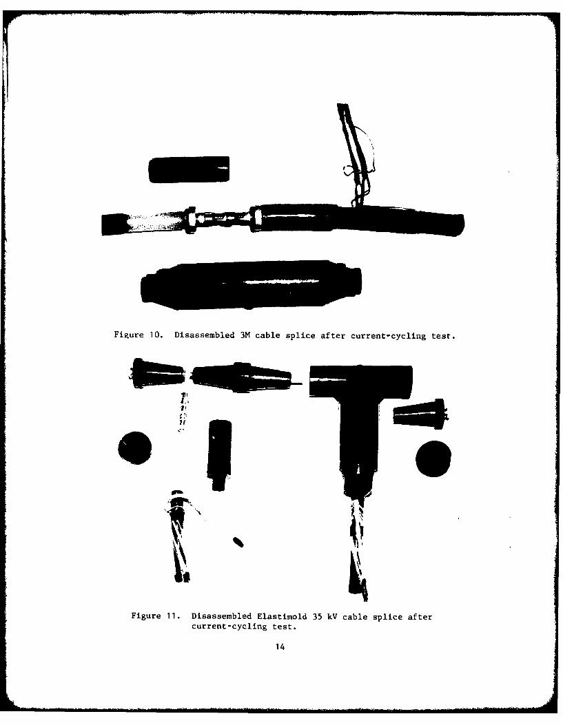
Figure 10. Disassembled 3M cable splice after current-cycling test.
Figure 11. Disassembled Elastimold 35 kV cable splice after
current-cycling test.
14

CONCLUSIONS
The cable splicing and termination kits tested were simple toinstall for an electrician without prior cable splicing experience.Both premolded cable splices and handwrapped cable splices required thesame careful cable preparation. After the cable was prepared, thepremolded cable splices and terminations slipped on in a few minutes,while the handwrapped cable splices and terminations required a longtedious task of handwrapping with insulating and semiconducting tape.This additional task for handwrapped cable splices and terminationsincreases the chances for human error.
All of the samples tested gave a good watertight splice. Therewere no signs of moisture or salt in the cable splices when they weredissassembled after the testing. All the test samples had corona extinc-tion voltages well above their designed operating voltages. The premoldedcable splices are tested by the manufacturer to assure that all of thecable splices marketed have corona extinction levels above the designedoperating voltage. This cannot be done with handwrapped cable splices,where the corona extinction level is determined by the skill of thecable splicer.
RECOMMENDATIONS
The pre-molded cable splices and cable terminations produce thehighest quality with minimum training of the personnel installing thedevices. This type of device should be used especially where theinstalling personnel do not perform frequent splices or in locationswhere rapid restoration of electrical service is required.
The premolded devices are designed for solid dielectric insulatedcable of given dimensions. The cable size and insulation thickness at agiven facility should be standardized wherever possible. However, ifthere are many different sizes of cable at a facility, different cablesplices will be required for each size. This may make premolded cablesplices uneconomical. However, this may be a minor problem becausedifferent sized cables can be spliced using only two premolded cablesplice body sizes; cable dimension variations are taken care of with acable adaptor. If several cable sizes are used, the appropriate cableadaptors can be purchased to handle any cable size while only purchasingthe number of cable splice bodies required.
15

Appendix
DISCUSSION OF HIGH VOLTAGE CABLE TERMINATION
The electric field inside a cable with concentric conductors is:
Va - Vba br Ln a/b
where E is the electric field at a radius r
V is the voltage at radius aa
Vb is the voltage at radius b
L is log base En
In the case of a 35 kV, 3/0, aluminum conductor cable a = 0.279inches and b - 0.624 inches. If a voltage of 35,000/ 3 volts isimposed on the conductors, the electric field next to the outer conductoris 40.2 volts/mil, and the electric field next to the center conductoris 90.0 volts/mil. The electric field that will break down air or causecorona is about 80 volts/mil. If the dielectric material was airinstead of a solid dielectric, or if the solid dielectric contained airbubbles, the electric field next to the center conductor would be largeenough to cause corona.
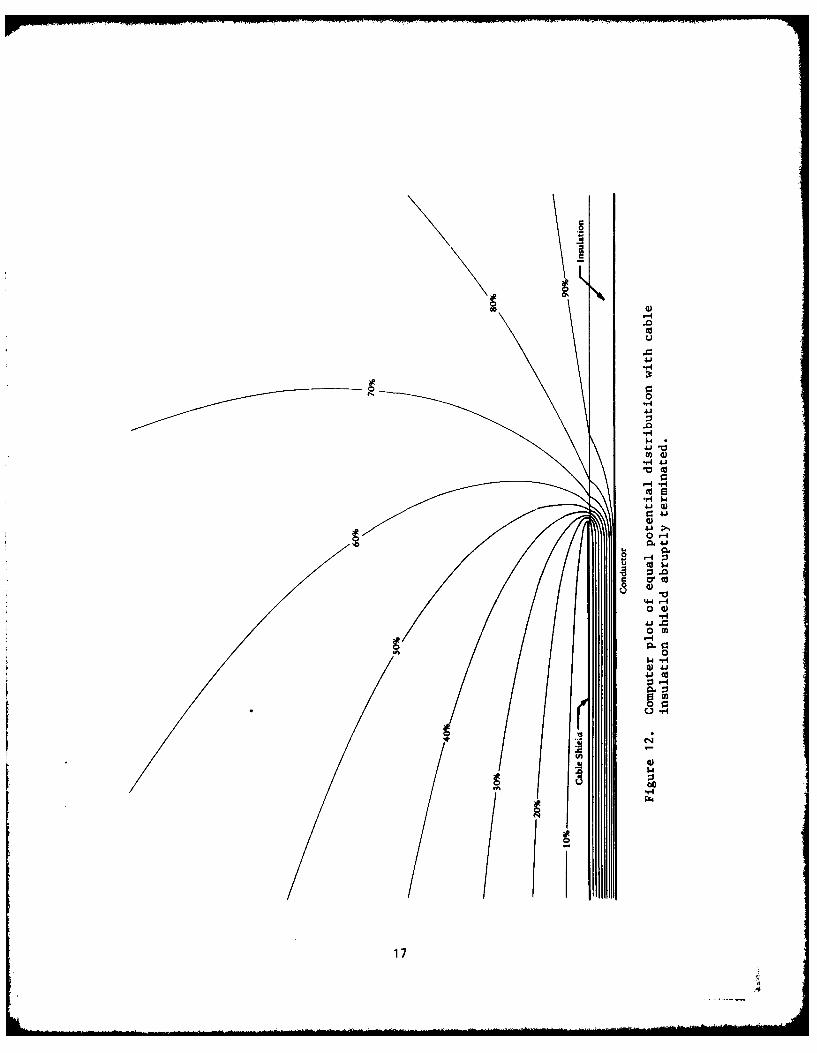
If the outer conductor (or shield) of the cable is abruptly terminated,the voltage distribution is radically modified as shown in Figure 12.Since E - -VV the electric field in Figure 12 is extremely high on thesurface of the insulation next to the termination of the shield. Themagnitude of the electric field is large enough to cause corona.
If a stress-relief cone is added to move the ground potentialfarther from the center conductor as in Figure 13, the magnitude of theelectric field in the air is lower than the value required to causecorona.
16
a.2
-H
4-
4i
0
0 4)0~-H
0
00)
'4
4J
174.

u 0)
CC
H 0
- -
00
Cd
0)
4-4
4
-4
0
-M
U-,4
18:

DISTRIBUTION LIST
SNDL No. of TotalCode Activities Copies
1 12 Defense Documentation Center
FKAIC 1 10 Naval Facilities EngineeringCommand
FKNI 6 6 NAVFAC Engineering Field Divisions
FKN5 9 9 Public Works Centers
FA25 1 1 Public Works Center
6 6 RDT&E Liaison Officers at NAVFACEngineering Field Divisions
256 260 CEL Special Distribution List No.5 for persons and activitiesinterested in reports on ElectricalSystems (including power conditioningand EMI)
19