Embed Size (px)
Citation preview

Agilent FieldFox RF Analyzer N9912A 4/6 GHz
Technical Overview
Boost your readiness in the field

2
FieldFoxEvery piece of gear in your kit had
to prove its worth. Measuring up
and earning a spot is the driving
idea behind Agilent’s FieldFox RF
analyzers. It starts with adapt-
ability: every operating mode is
fl exible enough to meet the needs
of novices and experts alike. To
accelerate your work, each mode
has a task-driven interface that
saves time in the fi eld. Best of all,
FieldFox is designed to withstand
your toughest working condi-
tions.
Step up to FieldFox -- and
achieve more in the fi eld.
Boost Your Readiness
2

3
Key differentiators
• Integrated QuickCal calibrates without
a calibration kit
• Immediate calibration with CalReady
• 50 percent faster than traditional
handheld instruments
• Superior dynamic range (96 dB) and
sensitivity (-148 dBm) in the spectrum
analysis mode
3
FieldFox
World’s Most Integrated Handheld RF Analyzer
Key measurements
Seven-in-one• Cable and antenna test, distance-to-fault,
return loss, cable loss
• Vector network analysis with Smith
chart display and time domain
• Vector voltmeter
• Spectrum analyzer, CHP, ACPR, OBW
• Interference analyzer, spectrogram, waterfall, record and playback
• Independent source, CW and tracking
• Power meter (USB), and channel power
meter (built-in)
Cable and antenna analyzer
Vector network analyzer2 MHz to 4/6 GHz
Spectrum analyzer100 kHz* to 4/6 GHz
*Useable to 5 kHz
Signal source 2 MHz to 4/6 GHz

44
Pick up FieldFox for its ergonomics FieldFox
Anti-glare 6.5 inch LCD display with LED backlight
Backlit keypadDedicated marker keys for quick marker function access
11.5” H
292 mm
7.4” W
188 mm
Convenient sidestrap makes iteasy to hold andcarry
Connector covershelp keep dust out
Task-driven keysare grouped toeasily andnaturally performstandard fi eldmeasurements
Portrait design and large buttons for easy operation — even with gloves on

55
FieldFox
2.8” D
72 mm
External referenceand external trigger
Spacious connector design makes connections fast and simple
Connector bay protects RF connectors
USB ports for convenient data transfer and GPS receiver
Simplify interference analysis with AM/FM tune and listen
Easily accessible battery compartment
Gasketed doors protect ports from moisture
SD fl ash card slot for additional data storage
LAN port for fast data transfer and SCPI programming
Quick-connectshoulder strap clips
RF InRF Out
…and depend on its durability and convenience
6
Key Measurements
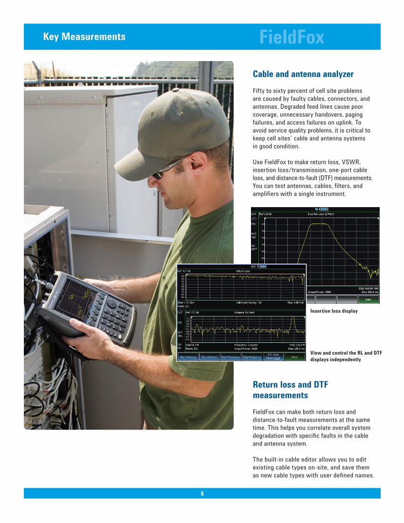
Cable and antenna analyzer
Fifty to sixty percent of cell site problems
are caused by faulty cables, connectors, and
antennas. Degraded feed lines cause poor
coverage, unnecessary handovers, paging
failures, and access failures on uplink. To
avoid service quality problems, it is critical to
keep cell sites’ cable and antenna systems
in good condition.
Use FieldFox to make return loss, VSWR,
insertion loss/transmission, one-port cable
loss, and distance-to-fault (DTF) measurements.
You can test antennas, cables, fi lters, and
amplifi ers with a single instrument.
Return loss and DTF measurements
FieldFox can make both return loss and
distance-to-fault measurements at the same
time. This helps you correlate overall system
degradation with specifi c faults in the cable
and antenna system.
The built-in cable editor allows you to edit
existing cable types on-site, and save them
as new cable types with user defi ned names.
FieldFox
6
Insertion loss display
View and control the RL and DTF
displays independently

7
Measurements in the fi eld without the need to manually calibrate
Each instrument is CalReady at the RF Out
port, immediately following power-on or
preset. This means it’s already calibrated and
ready to make accurate measurements such
as one-port cable loss, VSWR, return loss,
and DTF measurements at the test port.
Industry’s fi rst and only QuickCal
The industry’s fi rst and only built-in calibra-
tion system allows you to calibrate the cable/
antenna tester without carrying a calibration
kit into the fi eld. As with any test instrument,
when you add an additional device to the test
port, such as a jumper cable or attenuator, you
need to calibrate using a calibration kit (cal kit).
QuickCal eliminates the hassle of carrying
and using a cal kit, plus provides worry-free
accuracy and excellent repeatability every
time.
Broadband calibration
FieldFox allows you to make broadband
calibrations, which means the instrument is
calibrated over the maximum frequency span.
After a broadband calibration, you can change
the frequency range or number of points with-
out recalibrating the instrument.
FieldFox
7
Calibration Wizard
8
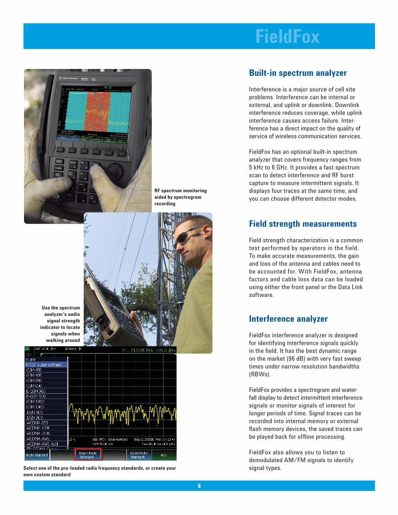
Built-in spectrum analyzer
Interference is a major source of cell site
problems. Interference can be internal or
external, and uplink or downlink. Downlink
interference reduces coverage, while uplink
interference causes access failure. Inter-
ference has a direct impact on the quality of
service of wireless communication services.
FieldFox has an optional built-in spectrum
analyzer that covers frequency ranges from
5 kHz to 6 GHz. It provides a fast spectrum
scan to detect interference and RF burst
capture to measure intermittent signals. It
displays four traces at the same time, and
you can choose different detector modes.
Field strength measurements
Field strength characterization is a common
test performed by operators in the field.
To make accurate measurements, the gain
and loss of the antenna and cables need to
be accounted for. With FieldFox, antenna
factors and cable loss data can be loaded
using either the front panel or the Data Link
software.
Interference analyzer
FieldFox interference analyzer is designed
for identifying interference signals quickly
in the fi eld. It has the best dynamic range
on the market (96 dB) with very fast sweep
times under narrow resolution bandwidths
(RBWs).
FieldFox provides a spectrogram and water-
fall display to detect intermittent interference
signals or monitor signals of interest for
longer periods of time. Signal traces can be
recorded into internal memory or external
fl ash memory devices, the saved traces can
be played back for offl ine processing.
FieldFox also allows you to listen to
demodulated AM/FM signals to identify
signal types.
FieldFox
8
RF spectrum monitoring
aided by spectrogram
recording
Use the spectrum
analyzer’s audio
signal strength
indicator to locate
signals when
walking around
Select one of the pre-loaded radio frequency standards, or create your
own custom standard
9
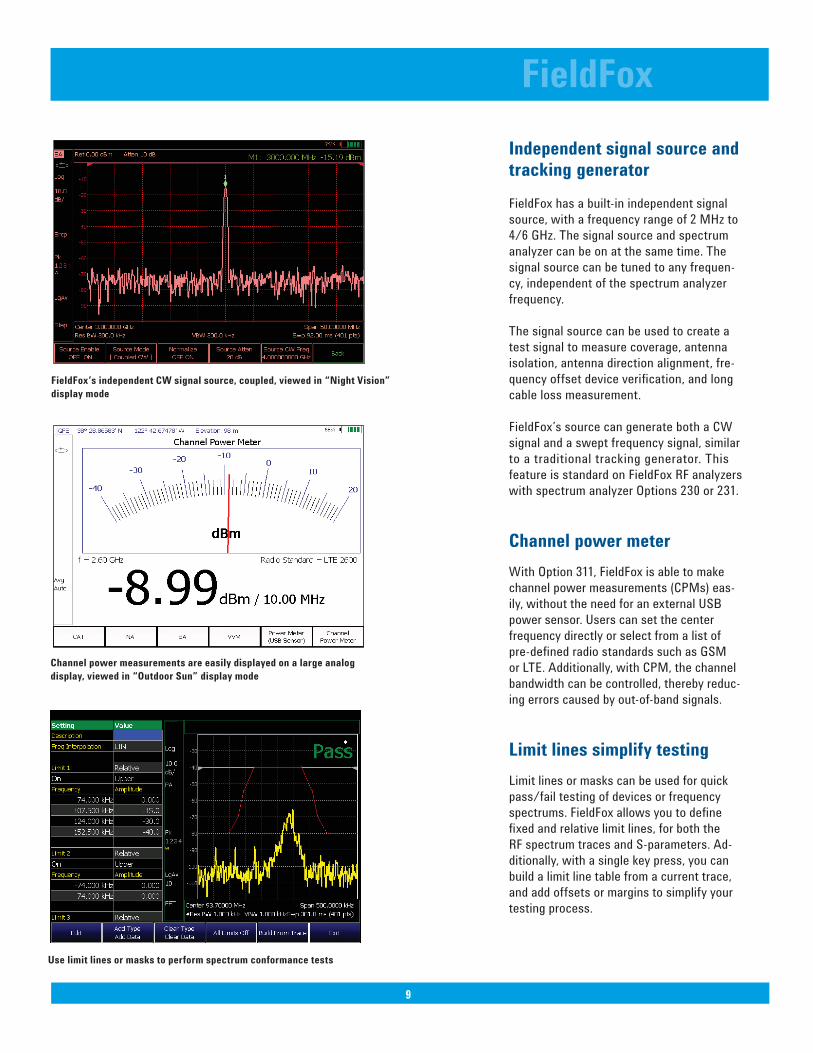
Independent signal source and tracking generator
FieldFox has a built-in independent signal
source, with a frequency range of 2 MHz to
4/6 GHz. The signal source and spectrum
analyzer can be on at the same time. The
signal source can be tuned to any frequen-
cy, independent of the spectrum analyzer
frequency.
The signal source can be used to create a
test signal to measure coverage, antenna
isolation, antenna direction alignment, fre-
quency offset device verifi cation, and long
cable loss measurement.
FieldFox’s source can generate both a CW
signal and a swept frequency signal, similar
to a traditional tracking generator. This
feature is standard on FieldFox RF analyzers
with spectrum analyzer Options 230 or 231.
Channel power meter
With Option 311, FieldFox is able to make
channel power measurements (CPMs) eas-
ily, without the need for an external USB
power sensor. Users can set the center
frequency directly or select from a list of
pre-defi ned radio standards such as GSM
or LTE. Additionally, with CPM, the channel
bandwidth can be controlled, thereby reduc-
ing errors caused by out-of-band signals.
Limit lines simplify testing
Limit lines or masks can be used for quick
pass/fail testing of devices or frequency
spectrums. FieldFox allows you to defi ne
fi xed and relative limit lines, for both the
RF spectrum traces and S-parameters. Ad-
ditionally, with a single key press, you can
build a limit line table from a current trace,
and add offsets or margins to simplify your
testing process.
FieldFox
9
FieldFox’s independent CW signal source, coupled, viewed in “Night Vision”
display mode
Channel power measurements are easily displayed on a large analog
display, viewed in “Outdoor Sun” display mode
Use limit lines or masks to perform spectrum conformance tests

10
Network analyzer time domain
With the time domain Option, FieldFox com-
putes the inverse Fourier transform of the
frequency-domain data to display refl ection
or transmission coeffi cients versus time.
Time domain gating can be used to remove
unwanted responses such as connector
mismatch or cable discontinuities, and the
results can be displayed in either time or
frequency domain. FieldFox’s time domain
function supports both low pass mode and
band pass mode, enabling users to measure
both broadband and frequency-selective
devices.
Network analysis
S11, S11 phase, Smith chart and polar
display are available with Option 303 (Net-
work analysis capability). To obtain S21or
insertion loss/gain, users need to order
Option 110 (transmission measurement),
in addition to Option 303.
For in-fi xture measurements, use FieldFox’s
port extension or electrical delay capabil-
ity to easily extend the reference plane to
the device interface to provide accurate
measurements. You can use the electrical
delay capability to measure deviation from
linear phase by removing the linear portion
of the phase delay.
If you need to measure the magnitude and
phase of all four S-parameters, consider the
N9923A FieldFox RF VNA. Please refer to
Agilent FieldFox RF Vector Network Ana-
lyzer, literature part number 5990-5087EN.
FieldFox
10
Use time domain gating to remove unwanted responses. Before gating:
Traces 1 and 3, After gating: Traces 2 and 4.
Device input impedance displayed on a Smith chart
The marker bandwidth/Q factor function simplifi es fi lter testing and tuning.
11
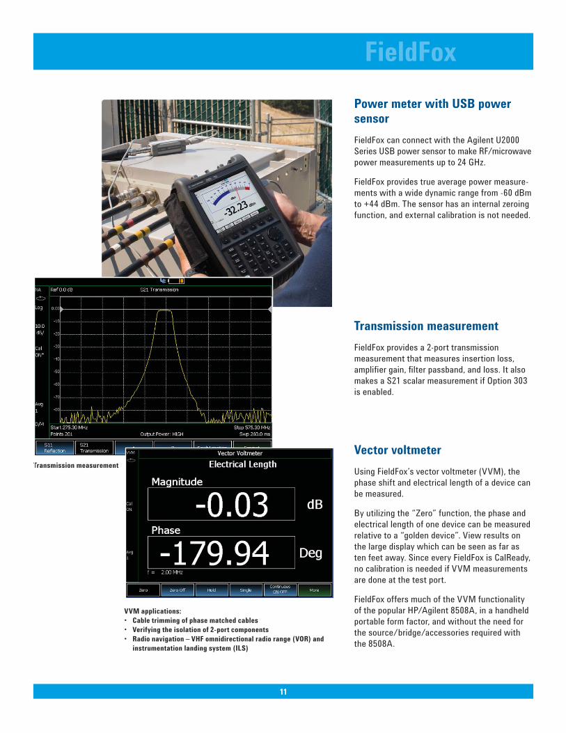
Power meter with USB power sensor
FieldFox can connect with the Agilent U2000
Series USB power sensor to make RF/microwave
power measurements up to 24 GHz.
FieldFox provides true average power measure-
ments with a wide dynamic range from -60 dBm
to +44 dBm. The sensor has an internal zeroing
function, and external calibration is not needed.
Transmission measurement
FieldFox provides a 2-port transmission
measurement that measures insertion loss,
amplifi er gain, fi lter passband, and loss. It also
makes a S21 scalar measurement if Option 303
is enabled.
Vector voltmeter
Using FieldFox’s vector voltmeter (VVM), the
phase shift and electrical length of a device can
be measured.
By utilizing the “Zero” function, the phase and
electrical length of one device can be measured
relative to a “golden device”. View results on
the large display which can be seen as far as
ten feet away. Since every FieldFox is CalReady,
no calibration is needed if VVM measurements
are done at the test port.
FieldFox offers much of the VVM functionality
of the popular HP/Agilent 8508A, in a handheld
portable form factor, and without the need for
the source/bridge/accessories required with
the 8508A.
FieldFox
11
Transmission measurement
VVM applications:
• Cable trimming of phase matched cables
• Verifying the isolation of 2-port components
• Radio navigation – VHF omnidirectional radio range (VOR) and
instrumentation landing system (ILS)

Comprehensive measurement capabilities
Cable and antenna
test
• Return loss, VSWR
• Distance-to-fault
Return loss/VSWR measurements allow you to evaluate the impedance matching performance of the feed line across the
frequency range of interest.
Distance-to-fault measurements help you identify the faults along a feed line. Use these measurements to precisely pinpoint the location of damaged or degraded antennas, connectors,
amplifi ers, fi lters, and duplexers, etc.
FieldFox provides up to 1001 data-point resolution to help accu-rately locate faults and extend measurement distance.
Transmission test
• Cable loss
• Insertion loss
• Amplifi er gain
Transmission test is used to accurately measure cable loss, insertion loss (fi lters), and amplifi er gain (tower mounted ampli-fi er). FieldFox offers two-port transmission magnitude measure-ments with up to 72 dB dynamic range.
One-port cable loss For already-installed cables, FieldFox accurately measures cable loss via the RF Out port. The instrument measures actual cable loss, without the need for additional computation.
CalReady at test port Each instrument is calibrated at the RF Out port. When you power up the instrument, it is ready to make accurate measure-ments such as one-port cable loss, VSWR, return loss, and DTF at the test port.
QuickCal The industry’s-fi rst and only built-in calibration system allows you to calibrate the cable and antenna tester without carrying a calibra-tion kit with you all the time. It provides worry-free accuracy and excellent repeatability. QuickCal also corrects drift errors caused by temperature changes during instrument operation.
Mechanical
calibration
Open-short-load (OSL) is standard in FieldFox. There are four calibration kits defi ned in the instrument.
Spectrum analysis The built-in spectrum analyzer allows you to scan up to 6 GHz and detect internal and external interference. FieldFox can detect sig-nals as low as -148 dBm up to 6 GHz, with phase noise of -88 dBc at 10 kHz, and a third order intercept (TOI) better than +18 dBm.
Limit lines Use limit lines or masks for pass/fail testing. You can set up both fi xed and relative limit lines, or build a limit line table from a current trace.
Interference analyzer Spectrogram and waterfall displays allow you to detect and monitor intermittent interference signals. The interested signals can be recorded and played back.
Field strength
measurements
Antenna factors and cable loss data can be loaded using either the front panel or the Data Link software. Field strength can bedisplayed in dBuV/m, dBuA/m, dBG or dBpT.
GPS Enables operators to fi nd exact locations and time/location stamp their measurement reports. The GPS information can be displayed on the screen and saved as part of the image, data or recorded signal.
FieldFox
12
Feature and Benefi t Summary
Perform and view return loss and distance-
to-fault measurements at the same time
Locate interference signals
Waterfall display

1313
Comprehensive measurement capabilities continued
Independent signal
source
Provides a test signal to measure coverage, antenna isolation, long
cable loss, frequency offset, and align antenna direction.
Power suite
measurements
Built-in spectrum analyzer provides one-button power suite measure-
ments such as; channel power, ACPR and OBW for LTE, WiMAX,
WCDMA, TD-SCDMA, cdma2000 and GSM measurements.
Custom radio
standards
Use one of the pre-loaded radio standards such as GSM 1900 or
WCDMA 850, or create your own custom radio standard using a
csv fi le.
AM/FM tune and
listen
The built-in spectrum analyzer can demodulate AM/FM modu-
lated signals and play the audio via speaker or headset. This
feature is very useful to identify types of signals.
Channel power meter Channel power meter measurements provide absolute power
measurements over a defi ned frequency bandwidth, without the
need for an external power sensor.
Power meter Makes accurate true average power measurements without
bringing a power meter along. The state-of-the-art Agilent USB
power sensors provide measurements up to 24 GHz.
Smith chart Smith charts can be used to display impedance matching charac-
teristics in cable and antenna systems.
Vector voltmeter The large vector voltmeter display makes it easy to match two or
more device’s electric length and ensure signals that travel on
different devices have the same delay.
Electrical delay Using the electrical delay function, you can remove the linear por-
tion of the phase shift and view the deviation from linear phase.
Port extension Allows you to extend the reference plan after calibration. This
feature is useful for measurements such as in-fi xture test,
where calibrating at the DUT or reference plane is cumbersome.
Network analyzer time domain
Using the time domain feature, you can display refl ection or trans-mission coeffi cients versus time. Time domain gating can be used to remove unwanted responses such as connector mismatch or cable discontinuities.
Make accurate true average power measure-
ments without bringing along a power meter
FieldFox
13
Channel power measurement

14
Transfl ective display makes it easy to read
measurements in direct sunlight
Water resistant chassis withstands wide
temperature ranges and humid environments
Modern connectivity
USB 2.0 ports Two USB 2.0 ports can be used to transfer fi les.
LAN port Used for data transfer and SCPI programming. Also used with
GPS receiver.
SD fl ash card slot Use as a data storage device.
FieldFox Data Link
software
Transfer data remotely from the instrument to a PC for back-
offi ce applications such as baseline analysis and report generation.
Field-proof usability
Transfl ective display
and backlit keys
The display is designed for easy viewing in indoor and outdoor
settings and in direct sunlight and darkness. Access different
display modes via softkeys.
Task-driven key design Front-panel keys are grouped to easily and naturally perform
standard fi eld measurements.
Speaker and
headphone jack
Used for demodulated audio signal capability.
One-button
measurement
Provides task-driven user interface to simplify the measurements.
Rugged design
Water-resistant chassis,
keypad and case design
The case is made from polycarbonates that withstand wide
temperature ranges and salty, humid environments.
RF connector
protection
A specially designed connector bay protects the RF connectors
from damage during drops or other external impacts.
Dust-free design With no vents or fans in the case, FieldFox resists dust for better
equipment reliability.
Meets tough environ-
mental standard
Meets MIL-PRF-28800F Class 2 specifi cation.
Gasketed doors Protects instrument interface from moisture.
FieldFox
14

15
FieldFox
Specifi cation (spec.):
Warranted performance. Specifi cations include guardbands to
account for the expected statistical performance distribution,
measurement uncertainties, and changes in performance due to
environmental conditions. The following conditions must be met:
• FieldFox has been turned on at least 10 minutes (unless other- wise stated)
• FieldFox is within its calibration cycle
• Storage or operation at 25 °C ±5 °C range (unless otherwise stated)
Typical (typ.):
Expected performance of an average unit over a 20 °C to 30 °C
temperature range, unless otherwise indicated; does not include
guardbands. It is not covered by the product warranty. The
FieldFox must be within its calibration cycle.
Nominal (nom.):
A general, descriptive term or design parameter. It is not tested,
and not covered by the product warranty.
Specifi cations
15
Cable and antenna analyzer (Option 104 or 106)
Frequency
Frequency range
Option 104 2 MHz1 to 4 GHz
Option 106 2 MHz2 to 6 GHz
Frequency reference
Accuracy ±2 ppm
Aging rate ±1 ppm/yr
Temperature stability ±1 ppm over -10 to 55 ºC
Frequency resolution
2 MHz to 1.6 GHz 2.5 kHz
> 1.6 GHz to 3.2 GHz 5 kHz
> 3.2 GHz to 6 GHz 10 kHz
Measurement speed
Return loss 1.5 ms/point (nominal) 1.75 GHz to 3.85 GHz, 1001 points, Cal ON
Distance-to-fault 2.4 ms/point (nominal) 0 to 500 ft, 601 points, Cal ON
Data points
101, 201, 401, 601, 801, 1001 (up to 10,001 using SCPI)
Directivity
Corrected > 42 dB
QuickCal (Option 111) > 42 dB (typical)3
Source match
Corrected > 36 dB
QuickCal (Option 111) ≥ 35 dB (typical) 3
Refl ection tracking
Corrected ± 0.06 dB
QuickCal (Option 111) ± 0.15 dB (typical) 3
A condensed version of the specifi cations is provided here. See the User’s Guide for the complete version;
http://cp.literature.agilent.com/litweb/pdf/N9912-90001.pdf
1. Spectrum analyzer (Option 230) start frequency is 100 kHz, usable to 5 kHz.
2. Spectrum analyzer (Option 231) start frequency is 100 kHz, usable to 5 kHz.
3. Requires 90 minute warm up

16
FieldFoxDynamic range
Refl ection (RF Out port)
2 MHz to 4 GHz 60 dB (typical)
> 4 GHz to 6 GHz 55 dB (typical)
Transmission measurement (Option 110)
2 MHz to 2 GHz 72 dB (typical)
> 2 GHz to 3 GHz 67 dB (typical)
> 3 GHz to 5 GHz 58 dB (typical)
> 5 GHz to 6 GHz 49 dB (typical)
Output power range
High power
2 MHz to 4 GHz < +8 dBm, +6 dBm (nominal)
> 4 GHz to 6 GHz < +7 dBm, +2 dBm (nominal)
Low power
2 MHz to 4 GHz < -23 dBm, -25 dBm (nominal)
> 4 GHz to 6 GHz < -24 dBm, -29 dBm (nominal)
Immunity to interference
+16 dBm (nominal)
Maximum input level (RF Out port)
+23 dBm
Maximum input DC voltage (RF Out port)
±50 VDC
16

17
FieldFoxCable and antenna measurements
Return loss
Display range 0 to 100 dB
Resolution 0.01 dB
VSWR
Display range 0 to 100
Resolution 0.01
Distance to fault (DTF)
• Range = (number of points - 1)/(span*2) x Vf (velocity factor in cable) x c (light speed)
• Resolution = range/(number of points - 1)
• Number of points: 101, 201, 401, 601, 801, 1001 (up to 10,001 using SCPI)
• Distance-to-fault display: return loss, VSWR, refl ection coeffi cient
Cable loss (1-port)
Terminated cable under test with short
Insertion loss (2-ports)
Requires Option 110
Transmission measurement (Option 110)
Frequency range
Option 104 2 MHz to 4 GHz
Option 106 2 MHz to 6 GHz
Dynamic range
2 MHz to 2 GHz 72 dB (typical)
2 GHz to 3 GHz 67 dB (typical)
> 3 GHz to 5 GHz 58 dB (typical)
> 5 GHz to 6 GHz 49 dB (typical)
17

18
FieldFox
Network analysis (Option 303)
S11 Vector measurement, S11 magnitude and S11 phase. Specifi cation is listed under Cable and
antenna analyzer section (S11/Return loss).
S21 Scalar measurement, S21 magnitude. Specifi cation is listed under transmission measurement.
S21 requires Option 110 transmission measurement.
A Refl ected power
R Source power
Display Log, linear, phase, VSWR, Smith chart, polar, group delay, unwrapped phase
Calibration types
Mechanical cal
QuickCal
Normalization
IF bandwidth selections
300 Hz, 1 kHz, 3 kHz, 10 kHz and 30 kHz
Data points
101, 201, 401, 601, 801, 1001, 1601, 4001, 10,001 (custom number of points can be set using SCPI)
Vector network analyzer time domain (Option 010)Using time domain, data from transmission or refl ection measurements in the frequency domain are converted to the time domain. The
time-domain response shows the measured parameter value versus time.
Time stimulus modes
Low-pass step This stimulus, similar to a traditional time domain refl ectometer (TDR) stimulus waveform, is
used to measure low-pass devices. The frequency-domain data should extend from DC
(extrapolated value) to a higher value.
Low-pass impulse This stimulus is also used to measure low-pass devices.
Bandpass impulse The bandpass impulse stimulates a pulsed RF signal and is used to measure the time-domain
response of band-limited devices.
Windows
The windowing function can be used to fi lter the frequency-domain data and thereby reduce overshoot and ringing in the time-
domain response.
Gating
The gating function can be used to selectively remove refl ection or transmission time-domain responses. In converting back to
the frequency domain the effects of the responses outside the gate are removed.
18

19
FieldFox
Spectrum analyzer (Option 230 or 231)
Frequency
Frequency range
Option 104 100 kHz to 4 GHz, usable to 5 kHz
Option 106 100 kHz to 6 GHz, usable to 5 kHz, tunable to 6.1 GHz
Frequency reference
Accuracy ±2 ppm
Frequency aging ±1 ppm/yr
Frequency reference
Temperature stability ±1 ppm over -10 to 55 °C
Frequency readout accuracy
± (readout frequency x frequency reference accuracy + RBW centering + 0.5 x horizontal resolution)
Frequency span
Range 0 Hz (zero span), 10 Hz to maximum frequency
Span accuracy ±(2 x RBW centering + horizontal resolution)
Span resolution 1 Hz
Resolution bandwidth (RBW)
Range (-3 dB bandwidth)
Zero span 300 Hz to 1 MHz in 1-3-10 sequence; 2 MHz
Non-zero span 10 Hz to 300 kHz in 1/1.5/2/3/5/7.5/10 sequence; 1 MHz, 2 MHz Accuracy 1 kHz to 1 MHz: ±5% (nominal)
10 Hz to 100 KHz non-zero span: ±1% (nominal)
2 MHz: ±10% (nominal)
300 Hz zero span: ±10% (nominal)
Selectivity (-60 dB/ -3 dB) 4:1 (nominal)
Video bandwidth (VBW)
Range 1 Hz to 2 MHz in 1/1.5/2/3/5/7.5/10 sequence
Stability
Noise sidebands, CF = 1 GHz 10 kHz offset: -88 dBc/Hz ( typical)
30 kHz offset: -89 dBc/Hz, (typical)
100 kHz offset: -95 dBc/Hz, (typical)
1 MHz offset: -115 dBc/Hz, (typical)
Sweep acquisition, span > 0 Hz
Range 1 to 5000, number of data acquisitions per trace point; value is normalized to the minimum
required to achieve amplitude accuracy with CW signals
Resolution 1
Readout Measured value representing time required to tune receiver, acquire data, and process trace
Trace updates
Span = 20 MHz, RBW = 3 kHz: 1.5 updates/second
Span = 100 MHz, RBW auto coupled: 7 updates/second
Span = 6 GHz, RBW auto coupled: 1 update/second
Trace points
101, 201, 401, 601, 801, 1001 points, default is 401
19

Amplitude
Measurement range
Displayed average noise level (DANL) to +20 dBm
Input attenuator range
0 to 31 dB, 1 dB steps
Maximum DC voltage at RF In port
±50 VDC
Maximum input power at RF In port
+27 dBm (0.5 W)
Displayed average noise level (DANL)
10 Hz RBW, 10 Hz VBW, 50 ohm termination on input, 0 dB attenuation, average detector
Preamplifi er OFF
20 to 30 °C
10 MHz to 2.4 GHz -130 dBm (typical)
> 2.4 GHz to 5.0 GHz -125 dBm (typical)
> 5.0 GHz to 6.0 GHz -119 dBm (typical)
Preamplifi er ON (Option 235)
20 to 30 °C
10 MHz to 2.4 GHz -148 dBm (typical)
> 2.4 GHz to 5.0 GHz -145 dBm (typical)
> 5.0 GHz to 6.0 GHz -138 dBm (typical)
-10 to 55 °C
10 MHz to 2.4 GHz < -141 dBm
> 2.4 GHz to 5 GHz < -138 dBm
> 5 GHz to 6 GHz < -130 dBm
Total absolute amplitude accuracy1
Peak detector, 10 dB attenuation, preamplifi er off, RBW < 2 MHz, input signal 0 dBm to -50 dBm, all settings auto-coupled
20 to 30 ºC
2 MHz to 10 MHz ±1.8 dB ±0.60 dB (typical)
> 10 MHz to 3.0 GHz ±1.5 dB ±0.50 dB (typical)
> 3.0 GHz to 5.0 GHz ±1.9 dB ±0.60 dB (typical)
> 5.0 GHz to 6.0 GHz ±2.1 dB ±0.60 dB (typical)
Second harmonic distortion (SHI)
-30 dBm signal at input mixer
2 MHz to 1.35 GHz < -70 dBc, +40 dBm SHI (nominal)
1.35 GHz to 3.0 GHz < -80 dBc, +50 dBm SHI (nominal)
FieldFox
20
1. Requires 90 minute warm up

Third order intermodulation distortion (TOI)
Two -30 dBm tones at input mixer, > 100 kHz tone separation
< -96 dBc, +18 dBm TOI (nominal)
Residual responses
Input terminated, 0 dB attenuation, preamplifi er off, RBW ≤ 1 kHz, VBW auto-coupled
20 MHz to 3 GHz -90 dBm (nominal)
> 3 GHz to 6 GHz -85 dBm (nominal)
Spurious responses
Input mixer level -30 dBm
RFsig = RFtune + 417 MHz -70 dBc (nominal)
RFsig = RFtune + 1.716 GHz -80 dBc (nominal)
Input mixer level -10 dBm, fi rst IF image response
RFsig = RFtune – 2 x 0.8346 GHz,
for RFtune 5.7 to 6.0 GHz -50 dBc (nominal)
Sidebands -80 dBc (nominal)
-60 dBc (nominal) when battery charging, 260 kHz offset
Preamplifi er (Option 235 requires Option 230 or 231)
Option 230 100 kHz to 4 GHz
Option 231 100 kHz to 6 GHz
Gain 22 dB (nominal)
Reference level
Range -170 dBm to +30 dBm
Resolution 0.1 dB
Accuracy 0 dB (no error)
Traces
4 traces, data/max/average/min
Detectors
Normal, positive peak, negative peak, sample, average
Markers
Marker types Normal, noise marker, band/interval marker, frequency counter marker
Number of markers or
delta markers 6
Marker functions Peak, next peak, peak left, peak right, marker to center, minimum search
RF In VSWR
1.5:1 (50 ohm)
Trigger
External, video trigger, FFT gating with video (IF envelope) trigger
FieldFox
21

Channel power meter (Option 311)Channel power meter is a built-in power measurement that does not require an external power sensor. Users can set the center frequency and channel bandwidth. The results are shown on a large analog display.
Frequency range
100 kHz to 4/6 GHz
Power accuracy1
Power meter measurement with USB sensor (Option 302)
Frequency range
9 kHz to 24 GHz (sensor dependent)
USB power sensor
9 kHz to 24 GHz, see Agilent U2000 Series USB power sensor specifi cations for details
General specifi cations
Connector type
Type-N (female)
Input impedance
50 ohm
External reference
Input type BNC female
Reference frequency 10 MHz
Required level -5 dBm to 10 dBm
Display
6.5” transfl ective, color VGA LED backlit 640 x 480 with anti-glare coating
Speaker
Built-in speaker
FieldFox
22
Independent signal source or tracking generatorThe independent source or tracking generator is included with either spectrum analyzer option 230 or 231. The source can be used in continuous wave (CW) or stimulus/response (S/R) mode. In CW mode, the source frequency is independent of the receiver frequency. The source can be tuned to a frequency that is different from the receiver. In stimulus/response mode, the source operates the same as a traditional tracking generator - the receiver tracks the source.
Frequency range
2 MHz to 4 GHz (Option 230) or 2 MHz to 6 GHz (Option 231)
Amplitude
High power 2 MHz to 4 GHz < +8 dBm, +6 dBm (nominal) Low power 2 MHz to 4 GHz <-23 dBm, -25 dBm (nominal)
>4 GHz to 6 GHz <+7 dBm, +2 dBm (nominal) >4 GHz to 6 GHz < -24 dBm, -29 dBm (nominal)
Attenuation 0 to 31 dB Functions Continuous wave, stimulus / response
Frequency range Spec Typical
2 MHz to 10 MHz ±1.8 dB ±0.60 dB
> 10 MHz to 3.0 GHz ±1.5 dB ±0.50 dB
> 3.0 GHz to 5.0 GHz ±1.9 dB ±0.60 dB
> 5.0 GHz to 6.0 GHz ±2.1 dB ±0.60 dB
1. Specifi cation requires 90 minute warm-up

23
General specifi cations continued
Headphone jack
Built-in headphone jack
Connectivity
2 x USB 2.0; 1 x mini USB; 1 x LAN
GPS
Latitude, longitude, elevation and accurate time are provided. The GPS information can be displayed on the screen, and saved as
part of the image, data, or recording fi le. The GPS capability is standard with all N9912A FieldFox RF analyzers. An external USB GPS
receiver is required. Agilent recommends the Microsoft Streets & Trips, or Microsoft AutoRoute with GPS locator.
Internal storage
Minimum 16 MB, up to 1000 traces
External storage
1 x micro SD slot and 2 x USB 2.0
EMC
Complies with European EMC Directive 2004/108/EC ▪ IEC/EN 61326-2-1) ▪ CISPR Pub 11 Group 1, Class A ▪ AS/NZS CISPR 11 ▪ ICES/NMB-001
ESD
▪ IEC/EN 61000-4-2, functional up to 20 kV test
Safety
Complies with European Low Voltage Directive 2006/95/EC • IEC/EN 61010-1 2nd Edition • Canada: CSA C22.2 No. 61010-1-04
• USA: UL 61010-1 2nd Edition
Environmental
Meets MIL-PRF-28800F Class 2 specifi cation
Humidity 95% at 40 °C
Temperature
Operating -10 ºC to +55 ºC
Non-operating -51 ºC to 71 ºC
Weight
6.2 lbs / 2.8 kg including battery
Dimensions (H x W x D)
11.5″ x 7.4″ x 2.8″ (292 x 188 x 72 mm)
Power
Power supply External DC input: 15 to 19 VDC
External AC power adapter
Input 100 to 250 VAC, 50 to 60 Hz; 1.25 to 0.56 A
Output 15 VDC, 4 A
Power consumption 12 W
Battery 6 cell Lithium Ion, 10.8 V, 4.6 A-h Battery operating time 4 hours
Languages
English, Chinese, French, Spanish, Japanese, Russian, German, Italian, and Turkish
FieldFox
23

N9912A FieldFox RF analyzer
FieldFox RF Analyzer base functions: One port cable and antenna analyzer (4 GHz), broadband calibration, CalReady, standard
mechanical cal kit support. Measurements include: return loss, distance-to-fault (DTF),
one port cable loss and VSWR.
Standard accessories included N9912A: AC/DC adapter; battery; soft carrying case comes with backpack and shoulder straps;
Quick Reference Guide; User’s Guide
N9912A FieldFox Options
Option 104 4 GHz cable and antenna analyzer
Option 106 6 GHz cable and antenna analyzer
Qption 110 Transmission measurement
Option 111 QuickCal
Option 230 4 GHz spectrum analyzer (requires Option 104)
Option 231 6 GHz spectrum analyzer (requires Option 106)
Option 235 Preamplifi er for spectrum analyzer (requires Option 230 or 231)
Option 236 Interference analyzer
Option 302 External USB power sensor support
Option 303 Network analysis capability
Option 308 Vector voltmeter
Option 010 Network analyzer time domain
Option 311 Channel power meter
N9912A upgrades
Product number Required Options
before upgrade Description before upgrade
N9912AU-110 Add transmission measurement capability None
Allows use of second port in NA and CAT modes.
N9912AU-111 Add QuickCal None
N9912AU-230 Add 4 GHz spectrum analyzer 4 GHz unit only, Option 104
May only be installed on 4 GHz instrument.
N9912AU-231 Add 6 GHz spectrum analyzer 6 GHz unit only, Option 106
May only be installed on 6 GHz instrument.
N9912AU-235 Add preamplifi er to spectrum analyzer Spectrum analyzer Option, 230 or 231
N9912AU-236 Add interference analyzer Spectrum analyzer Option, 230 or 231
N9912AU-302 Add external USB power sensor support None
N9912AU-303 Add network analyzer capability; one port only None
For second port, add Option 110.
N9912AU-308 Vector voltmeter None
N9912AU-010 Add network analyzer time domain Network analyzer Option 303
N9912AU-311 Add channel power meter None
FieldFox
24
Confi guration Information
The following upgrades are available for the N9912A FieldFox RF Analyzer. More information regarding upgrades is available at:
http://na.tm.agilent.com/fieldfox

25
N9910X RF/MW handheld analyzer accessories
N9910X-800 T-calibration kit, DC to 6 GHz, Type-N (m)
N9910X-801 T-calibration kit, DC to 6 GHz, Type-N (f)
N9910X-802 T-calibration kit, DC to 6 GHz, 7/16 DIN (m)
N9910X-803 T-calibration kit, DC to 6 GHz, 7/16 DIN (f)
85514A 4-in-1 OSLT mechanical calibration kit, DC to 9 GHz, Type-N (m), 50 ohm
85515A 4-in-1 OSLT mechanical calibration kit, DC to 9 GHz, Type-N (f), 50 ohm
N9910X-810 Rugged phase-stable cable, Type-N (m) to Type-N (m), 5 ft
N9910X-811 Rugged phase-stable cable, Type-N (m) to Type-N (f), 5 ft
N9910X-812 Rugged phase-stable cable, Type-N (m) to Type-N (m), 12 ft
N9910X-813 Rugged phase-stable cable, Type-N (m) to Type-N (f), 12 ft
N9910X-814 Rugged phase-stable cable, Type-N (m) to 7/16 (m), 5 ft
N9910X-815 Rugged phase-stable cable, Type-N (m) to 7/16 (m), 12 ft
N9910X-816 Rugged phase-stable cable, Type-N (m) to Type-N (f), 3.28 ft
N9910X-817 Rugged phase-stable cable, Type-N (m) to Type-N (m), 3.28 ft
N9910X-820 Antenna, directional, multiband, 800 to 2500 MHz, 10 dBi
N9910X-821 Antenna, telescopic whip, 70 MHz to 1 GHz
N9910X-843 Coaxial adapter, Type-N (m) to 7/16 DIN (f)
N9910X-845 Adapter kit: Type-N (f) to 7/16 DIN (f), Type-N (f) to 7/16 DIN (m), Type-N (f) to Type-N (f)
N9910X-846 Coaxial adapter, Type-N (m) 50 ohm to Type-N (f) 75 ohm (Recommend quantity 2 for 75 ohm measurements)
N9910X-860 Fixed attenuator, 40 dB, 100 W, DC to 3 GHz, Type-N (m) to Type-N (f)
N9910X-861 Fixed attenuator, 40 dB, 50 W, DC to 8.5 GHz, Type-N (m) to Type-N (f)
N9910X-870 Extra battery
N9910X-872 External battery charger
N9910X-873 AC/DC adapter
N9910X-874 External bias-tee, 2.5 MHz to 6 GHz, 1 W, 0.5 A
N9910X-875 DC car charger and adapter
N9910X-880 Extra soft carrying case with backpack and shoulder strap
N9910X-881 Hard transit case
For more information go to: www.agilent.com/find/fieldfox
FieldFox
25
Confi guration Information

FieldFox
26
FieldFox Accessories
T-Cal kits
Phase stable cable, N9910X-810
Antenna, N9910X-821
Directional antenna, N9910X-820 Bias-tees, N9910X-874
Adapter kit, N9910X-845
N9910X-800 N9910X-803N9910X-801 N9910X-802
FieldFox
26
Confi guration Information
DC car charger and adapter,
N9910X-875
100 Watt attenuator, N9910X-860
85514A 85515A

FieldFox
Soft carrying case with backpack and shoulder straps included with a standard N9912A.
For an extra soft carrying case order N9910X-880
FieldFox fi ts inside hard transit case
dddd shshouloulderder ststrapraps is inclncludeuded wd withith aa stastandandardrd N99N9912A12A
External battery charger,
N9910X-872
AC/DC adapter, N9910X-873
Hard transit case, N9910X-881
27