Embed Size (px)
Citation preview
Power Transmission & Distribution
Technical Performance
Cast Resin TransformersOil Immersed Transformer

Applications 6
Feature 7
Construction 8
Specification 9
Technical Data (ANSI Standard) 11
Technical Data (IEC Standard) 13
Manufacturing Process 15
Quality Assurance 16
Ordering Sheet 17
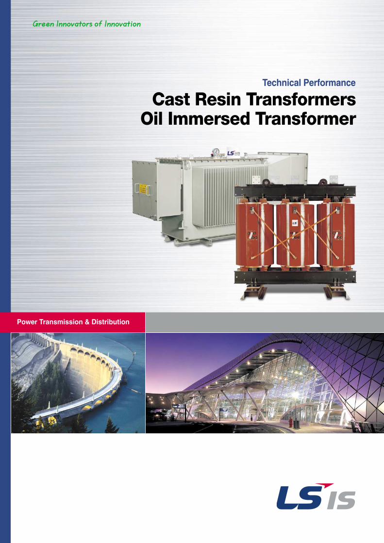
Cast Resin Transformers
LS Transformer
Contents
50kVA Through 15,000kVAPrimary Voltage: 2.3kV Through 36kV
Secondary Voltage: 120V Through 24kV
4II
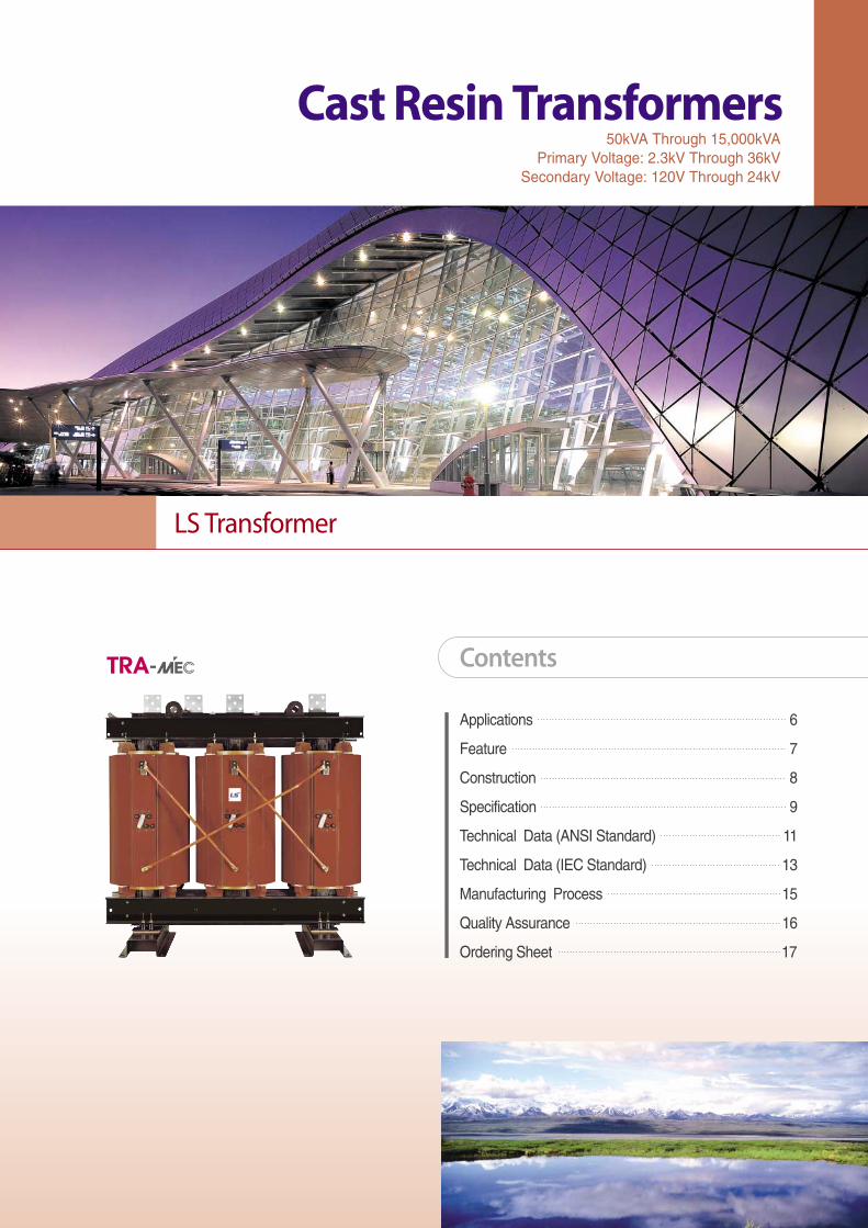
IntroductionGreat progress has been made in the development and improvement of
distribution transformers over the last decades.
The application of high quality insulation material and suitable selection of the coil
structure for high stress have contribute to the development of LS CAST RESIN
Transformers.
The LS CAST RESIN Transformer has succeeded in combining the advantage
of oil-filled and conventional dry type transformers, which are fabricated with an
epoxy resin. The windings are completely embeded under vacuum conditions.
This casting method makes it possible to assure void-free epoxy penetration of
both the inner layer and turn to turn insulation.
II5
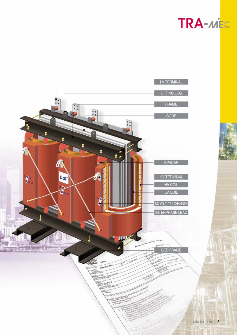
LV TERMINAL
LIFTING LUG
FRAME
CORE
SPACER
HV TERMINAL
HV COIL
NO VOLT. TAP CHANGER
INTERPHASE LEAD
BED FRAME
LV COIL
6II
Applications
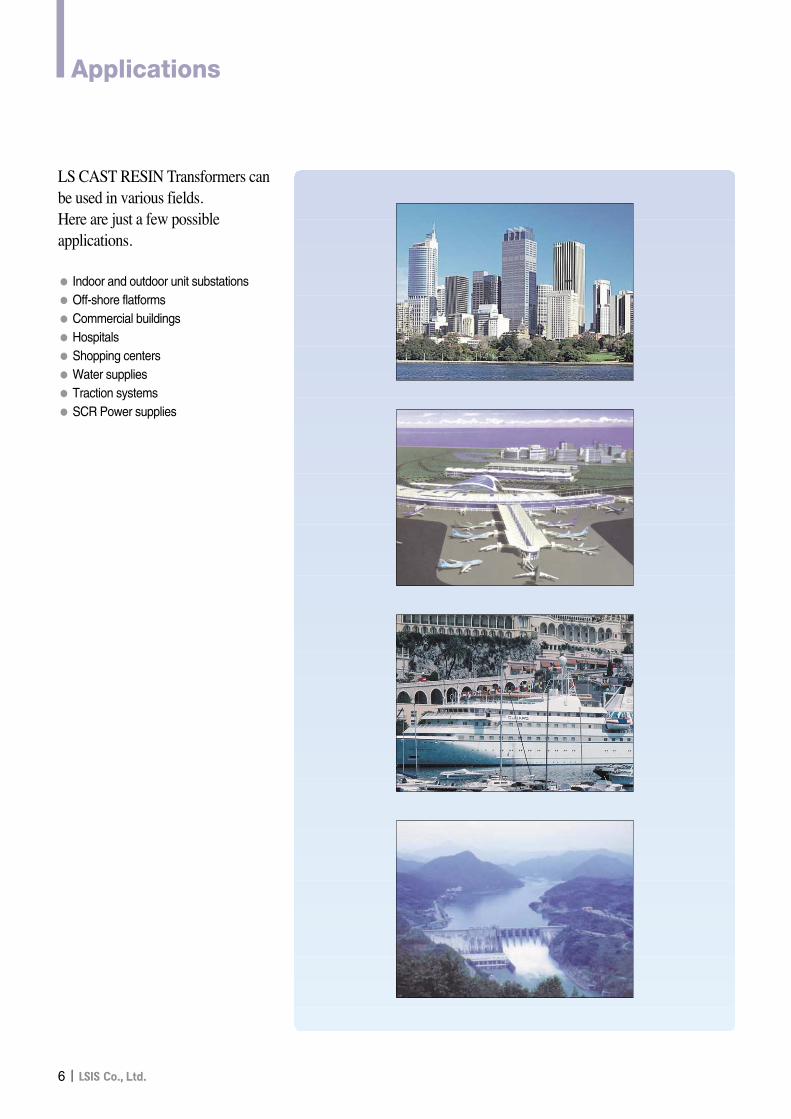
LS CAST RESIN Transformers canbe used in various fields.Here are just a few possibleapplications.
● Indoor and outdoor unit substations●Off-shore flatforms● Commercial buildings● Hospitals● Shopping centers●Water supplies● Traction systems● SCR Power supplies
II7
Cast Resin TransformersFeatures
LS CAST RESIN Transformers will not emit oil or toxic
gases into the atmosphere. Therefore, they do not pollute
the environment and are strongly recommended as a
replacement for askarel(PCB)-filled transformers.
Highfrequencygenerator
Filter
P.T
Chopping switch Input transformer Detertors
Coupling Capacitors
V
Environmentally safe
Based on the high thermal time constant factor of the
windings, LS CAST RESIN Transformers can be overloaded
for a short duration considerably higher than oil-immersed
transformers. It has a greater capability to withstand sudden
high overloads such as might be encountered in heavy
traction applications.
High overload capability
LS CAST RESIN Transformers are very resistant to impulse
voltage.
Impulse withstand levels to 200kV are available because of
careful design and special structure.
High impulse strength
Maintenance is almost completely eleminated. No checking
of liquid level and no dielectric test for moisture absorption is
required.
Due to the smooth coil surface, heavy dirt and dust build up
is eleminated even under the worst circumstances.
The recommended routine maintenance is an occasional
visual inspection.
Maintenance free
LS CAST RESIN Transformers have a very excellent
characteristic of self fire-extinguishing and fire resistance.
So there would be no fear of spread of fire even if fire took
place around the electricity room.
Fire resistant
The complete casting of coils under vacuum prevents the
penetration of moisture into the winding.
Therefore, it is suitable for both storage and operation in
harsh environment and is capable of being switched on
immediately after such storage without pre-drying.
Moisture proof
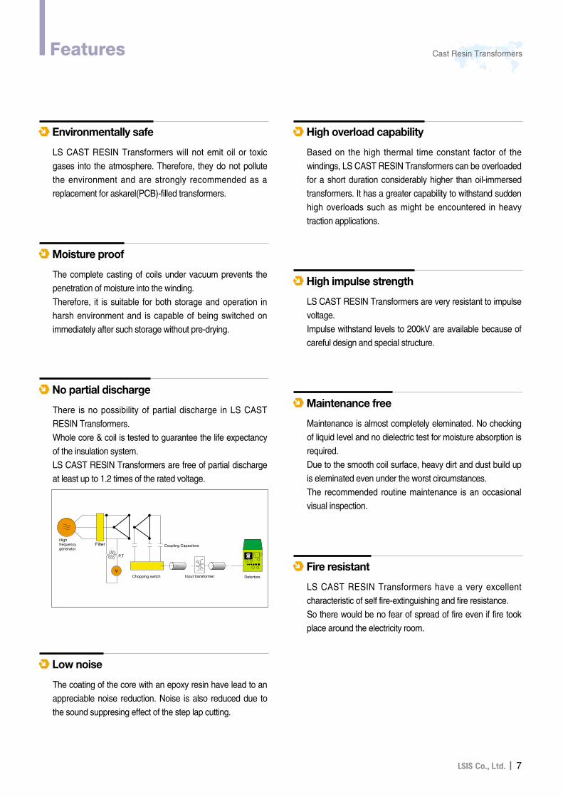
There is no possibility of partial discharge in LS CAST
RESIN Transformers.
Whole core & coil is tested to guarantee the life expectancy
of the insulation system.
LS CAST RESIN Transformers are free of partial discharge
at least up to 1.2 times of the rated voltage.
No partial discharge
The coating of the core with an epoxy resin have lead to an
appreciable noise reduction. Noise is also reduced due to
the sound suppresing effect of the step lap cutting.
Low noise
8II
Construction
LS CAST RESIN Transformers take pride in the ability to offer a wide variety of designs and configurationsnecessary to satisfy customer needs. Computer and CAD/CAM systems are used for quick and accurate designand manufacture to meet specific customer requirements.
The core is made of highest quality, cold rolled, grain-oriented, silicon steel and step lap joint. Three legs of the core are arranged in a single plane andinterconnected with a yoke. The legs are circular structure and are carefully interlacedwith stepwise arranged yokes. The core is mitred at a 45 degree angle and care-fully stackedand pressed to obtain low loss, exciting current and noise. The core is insulated on both side of each lamination andprotected against corrision by a resin coating and groundedin frame.The frame consists of upper and lower steel channels. Itholds the core and coil together. To protect against corrosion, all steel parts are coated withepoxy paint.
CORE & FRAME
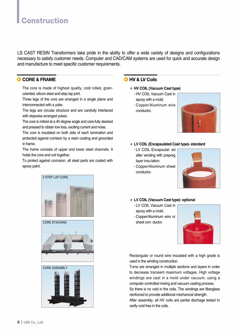
●● HV COIL (Vacuum Cast type)- HV COIL Vacuum Cast inepoxy with a mold.
- Copper/Aluminum wireconductor.
●● LV COIL (Encapsulated Cast type)- standard- LV COIL Encapsulat- edafter winding with prepreglayer insu-lation.
- Copper/Aluminum sheetconductor.
●● LV COIL (Vacuum Cast type)- optional- LV COIL Vacuum Cast inepoxy with a mold.
- Copper/Aluminum wire orsheet con- ductor.
Rectangular or round wire insulated with a high grade isused in the winding construction.Turns are arranged in multiple sections and layers in orderto decrease transient maximum voltages. High voltagewindings are cast in a mold under vacuum, using acomputer controlled mixing and vacuum casting process. So there is no void in the coils. The windings are fiberglassreinforced to provide additional mechanical strength. After assembly, all HV coils are partial dischage tested toverify void free in the coils.
HV & LV Coils
5 STEP LAP CORE
CORE STACKING
CORE ASSEMBLY
II9
Cast Resin TransformersSpecification
LS CAST RESIN Transformers are normally available withspecification as follows:
●● Rated voltageHV COIL : up to 36kVLV COIL : up to 600V* Dual High voltage coils can also be supplied.
●● Standard Tapping range : ±2.5%, ±5%* Other ratings are available by request
●● Power capacitySingle phase : 20 ~ 2,000kVAThree phase : 50 ~ 15,000kVA
●● Frequency : 50Hz, 60Hz* Other frequency is available by request
●●% Impedance voltageANSI STD. : 5.75%IEC STD. : 4 ~ 6.00%* Other % impedance voltages are available.
●● ConnectionsHV COIL : DeltaLV COIL : Star with neutral point* Other connections are available to meet requirement.
●● Temperature class(According to IEC 726)HV COIL and LV COIL : F CLASS* H class coils are available by request.
●● ConductorCopper (standard)Aluminum (optional)
●● Noise Level(according to NEMA Std.)500kVA - 60dB750kVA - 64dB1000kVA - 64dB1500kVA - 65dB2000kVA - 66dB2500kVA - 68dB*Noise reduction TRs are available by request.
Specification Data
LS CAST RESIN Transformers confirm to the requirementsof IEC 726(1982) standards.However we can also meet the requirements of the followingstandards, upon request.
●● ANSI / IEEE C57.12.01 (1998)General requirement for dry-type distribution and powertransformers.
●● CSA Standard C9-M1981Dry type transformers.
●● HD538.1,2,3(1995)3 Phase Dry type distribution transformers. 50Hz from 100kVA to 2500kVA
●● BS 7806 (1995)Dry type Power transformers
●● AS 2374 (1982)Power transformers* Transformers for rectifier applications and other special purposes
can be supplied according to the client’s specification.
Standards
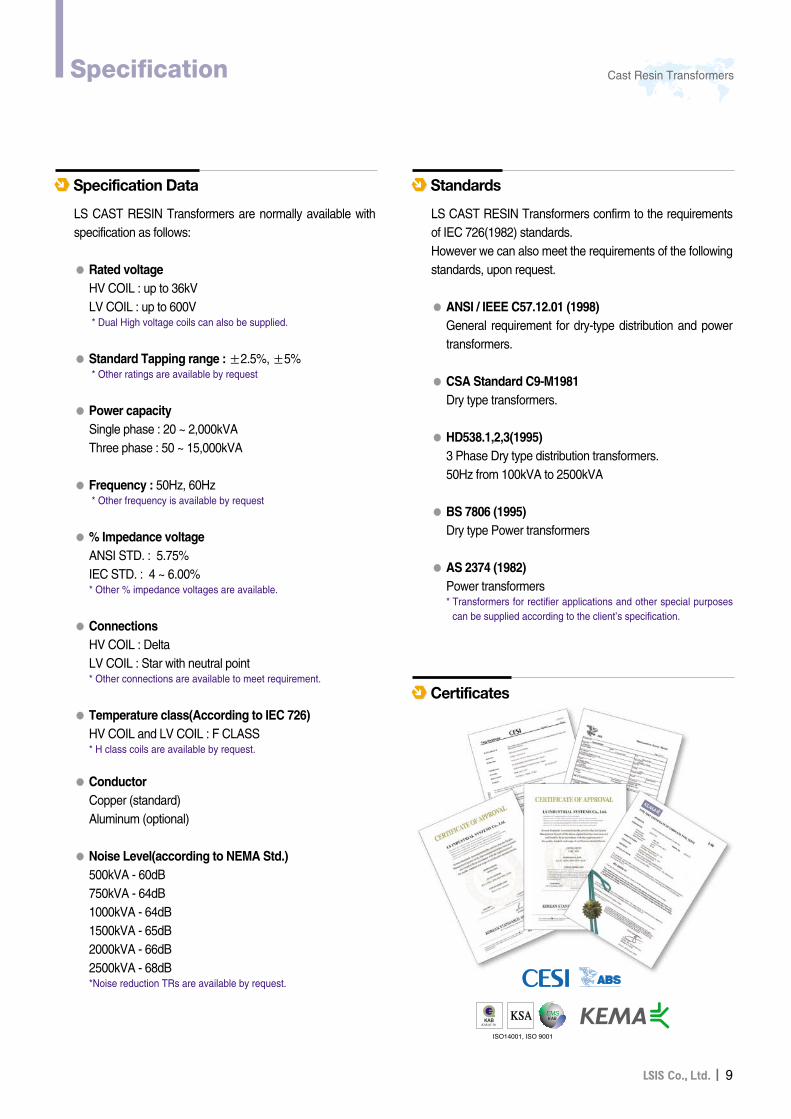
Certificates
10II
Specification
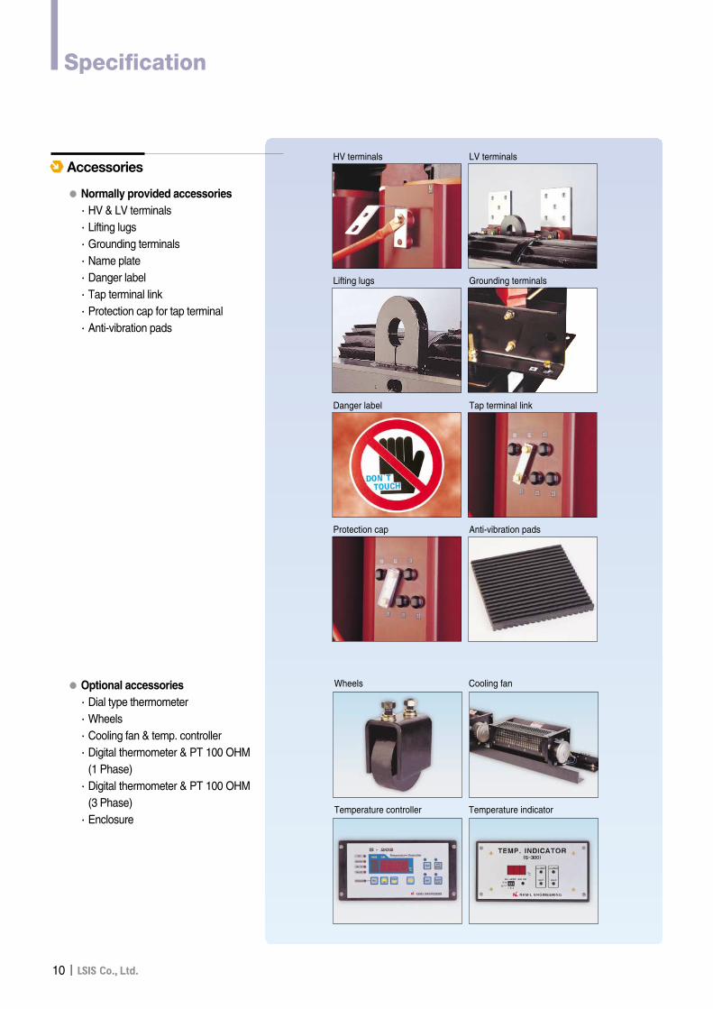
●● Normally provided accessories∙HV & LV terminals∙Lifting lugs∙Grounding terminals∙Name plate∙Danger label∙Tap terminal link∙Protection cap for tap terminal∙Anti-vibration pads
●● Optional accessories∙Dial type thermometer∙Wheels∙Cooling fan & temp. controller∙Digital thermometer & PT 100 OHM
(1 Phase)∙Digital thermometer & PT 100 OHM
(3 Phase)∙Enclosure
AccessoriesHV terminals LV terminals
Lifting lugs Grounding terminals
Danger label Tap terminal link
Protection cap Anti-vibration pads
Wheels Cooling fan
Temperature controller Temperature indicator
II11
Cast Resin TransformersTechnical Data (ANSI Standard)
x3x0 x2 x1
H3 H2 H1
W
D
2221 23
1211 13
2221 23
1211 13
2221 23
1211 13
x3 x2 x1
H3 H2 H1
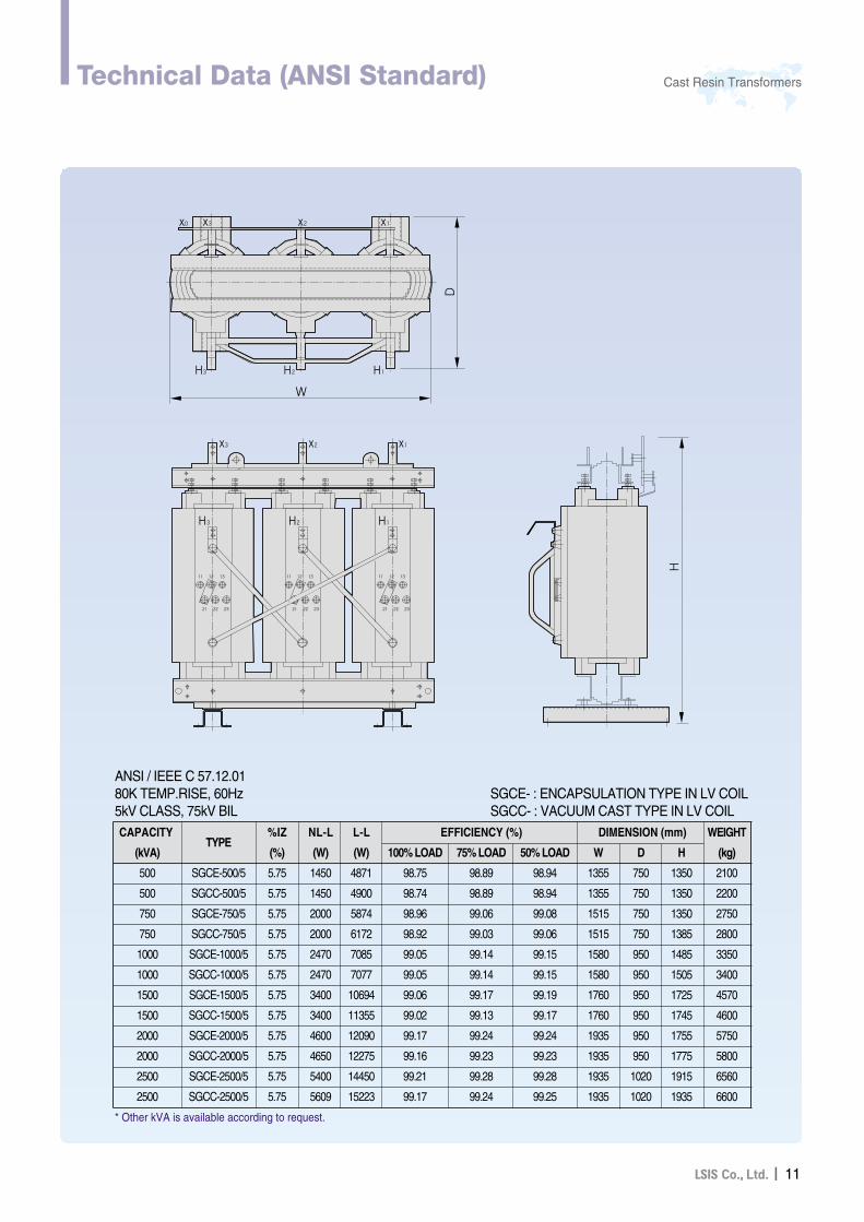
ANSI / IEEE C 57.12.0180K TEMP.RISE, 60Hz5kV CLASS, 75kV BIL
SGCE- : ENCAPSULATION TYPE IN LV COILSGCC- : VACUUM CAST TYPE IN LV COIL
CAPACITYTYPE
%IZ NL-L L-L EFFICIENCY (%) DIMENSION (mm) WEIGHT
(kVA) (%) (W) (W) 100% LOAD 75% LOAD 50% LOAD W D H (kg)
500 SGCE-500/5 5.75 1450 4871 98.75 98.89 98.94 1355 750 1350 2100
500 SGCC-500/5 5.75 1450 4900 98.74 98.89 98.94 1355 750 1350 2200
750 SGCE-750/5 5.75 2000 5874 98.96 99.06 99.08 1515 750 1350 2750
750 SGCC-750/5 5.75 2000 6172 98.92 99.03 99.06 1515 750 1385 2800
1000 SGCE-1000/5 5.75 2470 7085 99.05 99.14 99.15 1580 950 1485 3350
1000 SGCC-1000/5 5.75 2470 7077 99.05 99.14 99.15 1580 950 1505 3400
1500 SGCE-1500/5 5.75 3400 10694 99.06 99.17 99.19 1760 950 1725 4570
1500 SGCC-1500/5 5.75 3400 11355 99.02 99.13 99.17 1760 950 1745 4600
2000 SGCE-2000/5 5.75 4600 12090 99.17 99.24 99.24 1935 950 1755 5750
2000 SGCC-2000/5 5.75 4650 12275 99.16 99.23 99.23 1935 950 1775 5800
2500 SGCE-2500/5 5.75 5400 14450 99.21 99.28 99.28 1935 1020 1915 6560
2500 SGCC-2500/5 5.75 5609 15223 99.17 99.24 99.25 1935 1020 1935 6600
* Other kVA is available according to request.
12II
Technical Data (ANSI Standard)
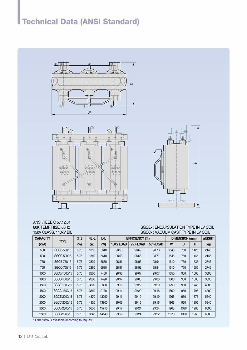
ANSI / IEEE C 57.12.0180K TEMP.RISE, 60Hz15kV CLASS, 110kV BIL
SGCE- : ENCAPSULATION TYPE IN LV COILSGCC- : VACUUM CAST TYPE IN LV COIL
CAPACITYTYPE
%IZ NL-L L-L EFFICIENCY (%) DIMENSION (mm) WEIGHT
(kVA) (%) (W) (W) 100% LOAD 75% LOAD 50% LOAD W D H (kg)
500 SGCE-500/15 5.75 1810 5610 98.53 98.69 98.73 1545 750 1425 2145
500 SGCC-500/15 5.75 1840 5610 98.53 98.68 98.71 1545 750 1445 2145
750 SGCE-750/15 5.75 2330 6630 98.81 98.93 98.94 1610 750 1535 2745
750 SGCC-750/15 5.75 2360 6630 98.81 98.92 98.94 1610 750 1555 2745
1000 SGCE-1000/15 5.75 2800 7480 98.98 99.07 99.07 1650 950 1665 3395
1000 SGCC-1000/15 5.75 2830 7490 98.97 99.06 99.06 1680 950 1685 3395
1500 SGCE-1500/15 5.75 3800 8880 99.16 99.22 99.20 1790 950 1745 4385
1500 SGCC-1500/15 5.75 3860 9130 99.14 99.20 99.18 1800 950 1795 4380
2000 SGCE-2000/15 5.75 4870 13050 99.11 99.19 99.19 1965 950 1875 5340
2000 SGCC-2000/15 5.75 4920 13900 99.06 99.15 99.16 1965 950 1905 5340
2500 SGCE-2500/15 5.75 5650 15210 99.17 99.24 99.24 1965 1020 1985 6600
2500 SGCC-2500/15 5.75 6240 14140 99.19 99.24 99.22 2070 1020 1965 6600
* Other kVA is available according to request.
x3x0 x2 x1
H3 H2 H1
W
D
2221 23
1211 13
2221 23
1211 13
2221 23
1211 13
x3 x2 x1
H3 H2 H1
II13
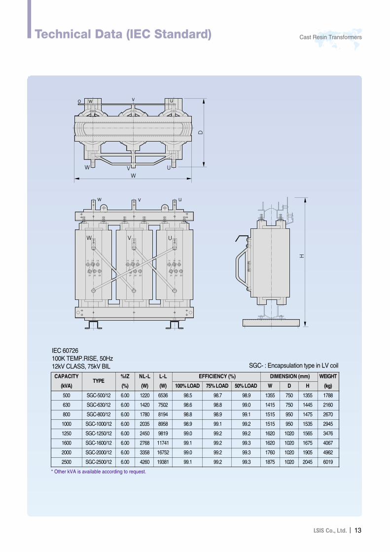
Cast Resin TransformersTechnical Data (IEC Standard)
CAPACITYTYPE
%IZ NL-L L-L EFFICIENCY (%) DIMENSION (mm) WEIGHT
(kVA) (%) (W) (W) 100% LOAD 75% LOAD 50% LOAD W D H (kg)
500 SGC-500/12 6.00 1220 6536 98.5 98.7 98.9 1355 750 1355 1788
630 SGC-630/12 6.00 1420 7502 98.6 98.8 99.0 1415 750 1445 2160
800 SGC-800/12 6.00 1780 8194 98.8 98.9 99.1 1515 950 1475 2670
1000 SGC-1000/12 6.00 2035 8958 98.9 99.1 99.2 1515 950 1535 2945
1250 SGC-1250/12 6.00 2450 9819 99.0 99.2 99.2 1620 1020 1565 3476
1600 SGC-1600/12 6.00 2768 11741 99.1 99.2 99.3 1620 1020 1675 4067
2000 SGC-2000/12 6.00 3358 16752 99.0 99.2 99.3 1760 1020 1905 4962
2500 SGC-2500/12 6.00 4260 19381 99.1 99.2 99.3 1875 1020 2045 6019
IEC 60726100K TEMP.RISE, 50Hz12kV CLASS, 75kV BIL
* Other kVA is available according to request.
o w v u
W
WV U
D
VW U
w v u
2221 23
1211 13
2221 23
1211 13
2221 23
1211 13
SGC- : Encapsulation type in LV coil
14II
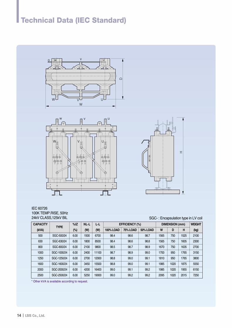
Technical Data (IEC Standard)
CAPACITYTYPE
%IZ NL-L L-L EFFICIENCY (%) DIMENSION (mm) WEIGHT
(kVA) (%) (W) (W) 100% LOAD 75% LOAD 50% LOAD W D H (kg)
500 SGC-500/24 6.00 1500 6700 98.4 98.6 98.7 1565 750 1525 2100
630 SGC-630/24 6.00 1800 8500 98.4 98.6 98.8 1565 750 1605 2300
800 SGC-800/24 6.00 2100 9800 98.5 98.7 98.9 1670 750 1635 2700
1000 SGC-1000/24 6.00 2400 11100 98.7 98.9 99.0 1700 950 1765 3150
1250 SGC-1250/24 6.00 2700 12000 98.8 99.0 99.1 1810 950 1765 3800
1600 SGC-1600/24 6.00 3450 15500 98.8 99.0 99.1 1985 1020 1875 5550
2000 SGC-2000/24 6.00 4200 16400 99.0 99.1 99.2 1985 1020 1955 6150
2500 SGC-2500/24 6.00 5250 19000 99.0 99.2 99.2 2095 1020 2015 7250
IEC 60726100K TEMP.RISE, 50Hz24kV CLASS,125kV BIL
* Other kVA is available according to request.
o w v u
W
WV U
D
VW U
w v u
2221 23
1211 13
2221 23
1211 13
2221 23
1211 13
SGC- : Encapsulation type in LV coil
II15
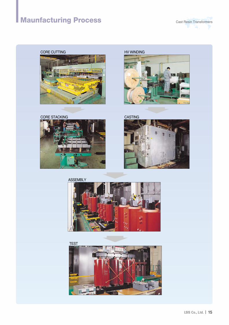
Cast Resin TransformersMaunfacturing Process
CORE CUTTING HV WINDING
CORE STACKING CASTING
ASSEMBLY
TEST
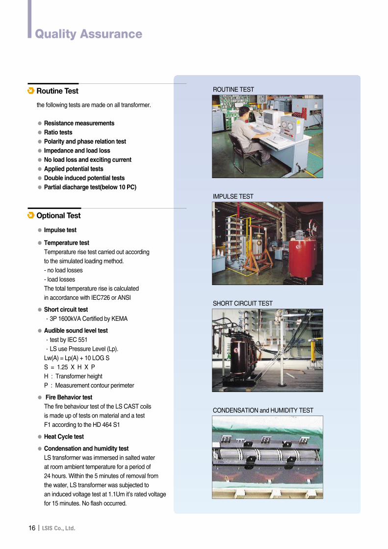
the following tests are made on all transformer.
●● Resistance measurements●● Ratio tests●● Polarity and phase relation test●● Impedance and load loss●● No load loss and exciting current●● Applied potential tests●● Double induced potential tests●● Partial diacharge test(below 10 PC)
Routine Test
●● Impulse test
●● Temperature testTemperature rise test carried out according to the simulated loading method. - no load losses- load lossesThe total temperature rise is calculated in accordance with IEC726 or ANSI
●● Short circuit test∙3P 1600kVA Certified by KEMA
●● Audible sound level test∙test by IEC 551∙LS use Pressure Level (Lp).Lw(A) = Lp(A) + 10 LOG SS = 1.25 X H X PH : Transformer heightP : Measurement contour perimeter
●● Fire Behavior testThe fire behaviour test of the LS CAST coils is made up of tests on material and a test F1 according to the HD 464 S1
●● Heat Cycle test
●● Condensation and humidity testLS transformer was immersed in salted water at room ambient temperature for a period of 24 hours. Within the 5 minutes of removal fromthe water, LS transformer was subjected to an induced voltage test at 1.1Um it’s rated voltagefor 15 minutes. No flash occurred.
Optional Test
16II
Quality Assurance
ROUTINE TEST
IMPULSE TEST
SHORT CIRCUIT TEST
CONDENSATION and HUMIDITY TEST
II17
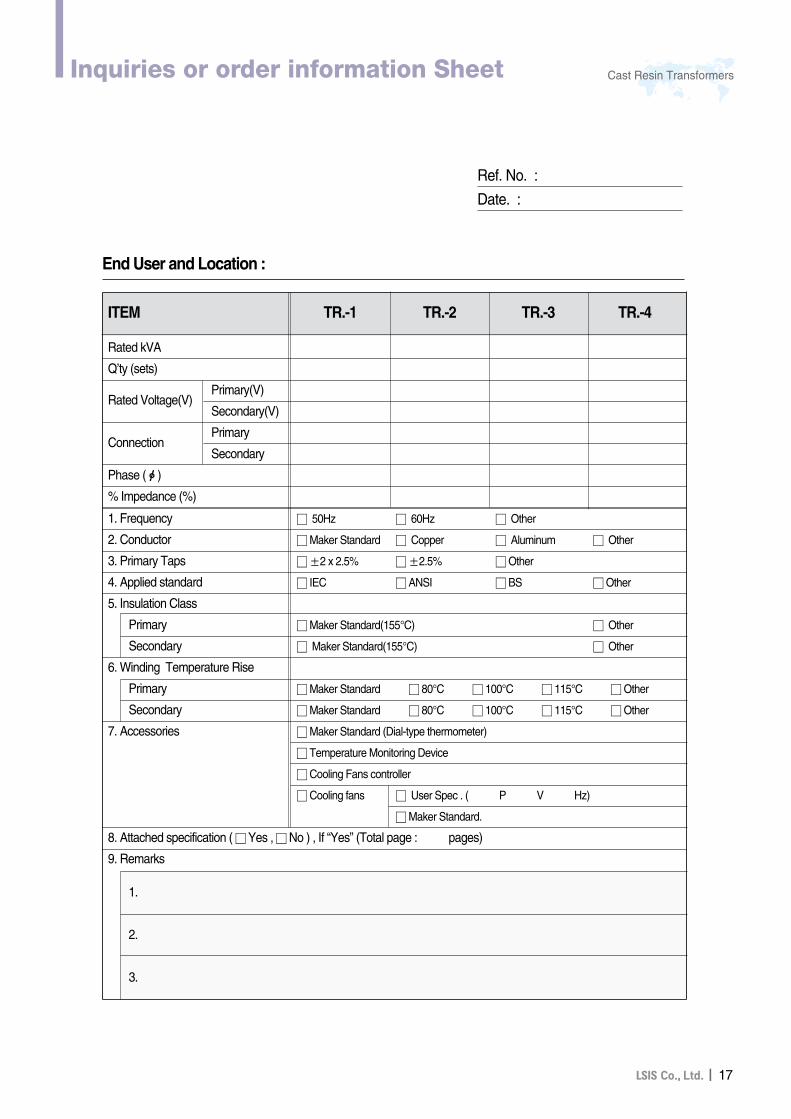
Cast Resin TransformersInquiries or order information Sheet
Ref. No. :
Date. :
End User and Location :
Rated kVA
Q’ty (sets)
Rated Voltage(V)Primary(V)
Secondary(V)
ConnectionPrimary
Secondary
Phase (ф)
% Impedance (%)
ITEM TR.-1 TR.-2 TR.-3 TR.-4
1. Frequency � 50Hz � 60Hz � Other
2. Conductor �Maker Standard � Copper � Aluminum � Other
3. Primary Taps �±2 x 2.5% �±2.5% �Other
4. Applied standard � IEC � ANSI � BS �Other
5. Insulation Class
Primary �Maker Standard(155°C) � Other
Secondary � Maker Standard(155°C) � Other
6. Winding Temperature Rise
Primary �Maker Standard � 80°C � 100°C � 115°C �Other
Secondary �Maker Standard � 80°C � 100°C � 115°C �Other
7. Accessories �Maker Standard (Dial-type thermometer)
� Temperature Monitoring Device
�Cooling Fans controller
�Cooling fans � User Spec . ( P V Hz)
�Maker Standard.
8. Attached specification ( �Yes , �No ) , If “Yes” (Total page : pages)
9. Remarks
1.
2.
3.

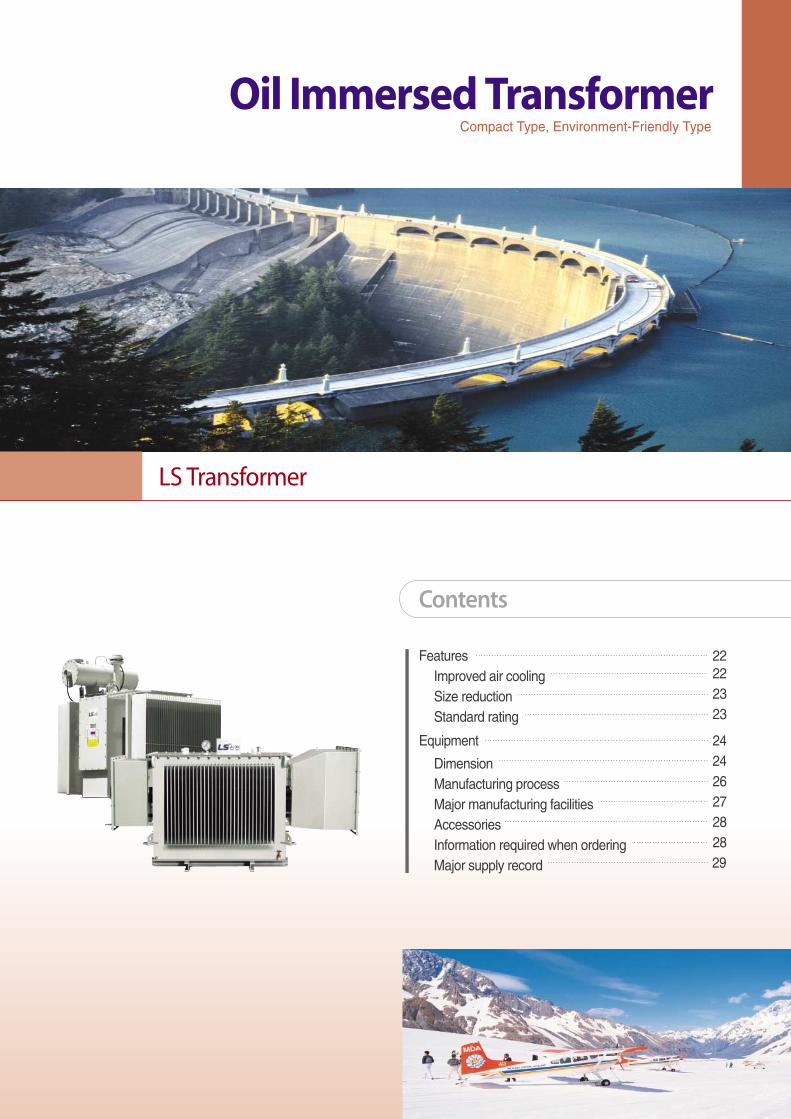
Features 22Improved air cooling 22
Size reduction 23
Standard rating 23
Equipment 24
Dimension 24
Manufacturing process 26
Major manufacturing facilities 27
Accessories 28
Information required when ordering 28
Major supply record 29
Oil Immersed Transformer
LS Transformer
Contents
Compact Type, Environment-Friendly Type
20II
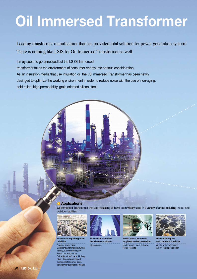
It may seem to go unnoticed but the LS Oil Immersed
transformer takes the environment of consumer energy into serious consideration.
As an insulation media that use insulation oil, the LS Immersed Transformer has been newly
desinged to optimize the working environment in order to reduce noise with the use of non-aging,
cold rolled, high permeability, grain oriented silicon steel.
Leading transformer manufacturer that has provided total solution for power generation system!
There is nothing like LSIS for Oil Immersed Transformer as well.
Nuclear power plant,Semiconductor manufacturingfactory, Automobile factoryPetrochemical factory, Drill ship, Wharf crane, Rollingplant, International airport,thermoelectric power plant,transformer substation, theater
Skyscrapers Underground mall, Subway,Hotel, Hospital
Waste water processing facility, Hydropower plant
Places that require rigorousreliability
Places with restrictiveinstallation conditions
Public places with muchemphasis on fire prevention
Places that requireenvironmental durability
Oil Immersed Transformer that use insulating oil have been widely used in a variety of areas including indoor andout door facilities.
Applications
Oil Immersed Transformer
II21
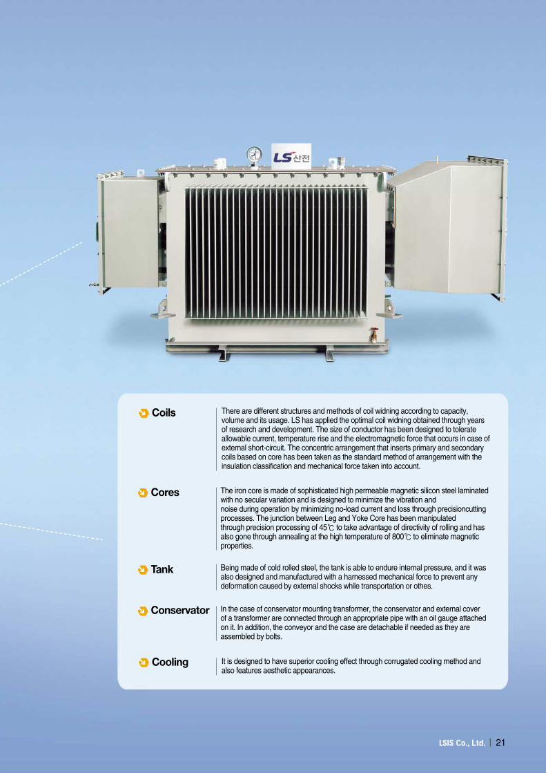
There are different structures and methods of coil widning according to capacity,volume and its usage. LS has applied the optimal coil widning obtained through yearsof research and development. The size of conductor has been designed to tolerateallowable current, temperature rise and the electromagnetic force that occurs in case ofexternal short-circuit. The concentric arrangement that inserts primary and secondarycoils based on core has been taken as the standard method of arrangement with theinsulation classification and mechanical force taken into account.
Coils
The iron core is made of sophisticated high permeable magnetic silicon steel laminatedwith no secular variation and is designed to minimize the vibration andnoise during operation by minimizing no-load current and loss through precisioncuttingprocesses. The junction between Leg and Yoke Core has been manipulatedthrough precision processing of 45℃ to take advantage of directivity of rolling and hasalso gone through annealing at the high temperature of 800℃ to eliminate magneticproperties.
Cores
Being made of cold rolled steel, the tank is able to endure internal pressure, and it wasalso designed and manufactured with a harnessed mechanical force to prevent anydeformation caused by external shocks while transportation or othes.
Tank
It is designed to have superior cooling effect through corrugated cooling method andalso features aesthetic appearances.
Cooling
In the case of conservator mounting transformer, the conservator and external coverof a transformer are connected through an appropriate pipe with an oil gauge attachedon it. In addition, the conveyor and the case are detachable if needed as they areassembled by bolts.
Conservator
22II
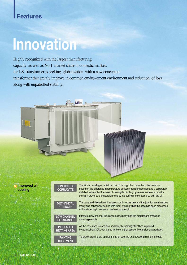
InnovationHighly recognized with the largest manufacturing
capacity as well as No.1 market share in domestic market,
the LS Transformer is seeking globalization with a new conceptual
transformer that greatly improve in common envirovement environment and reduction of loss
along with unpatrolled stability.
Improved aircooling
Traditional panel-type radiators cool off through the convection phenomenon based on the difference in temperature between transformer case and a separately installed radiator but the case of Corrugate Cooling System is made of a radiator so that it prevents a temperature rise by increasing the contact area with the air.
The case and the radiator has been combined as one and the junction area has been stably and cohesively welded with robot welding while the case has been processed with embossing to enhance mechanical strength.
It features low channel resistance as the body and the radiator are embodied as a single entity.
As the case itself is used as a radiator, the heating effect has improved by as much as 30%, compared to the one that uses only one side as a radiator.
To prevent rusting we applied the Shot peening and powder painting methods.
PRINCIPLE OFCORRUGATE
LOW CHANNELRESISTANCE
MECHANICALSTRENGTH
INCREASEDHEATING AREA
PAINTINGTREATMENT
Features
II23
Oil Immersed Transformer
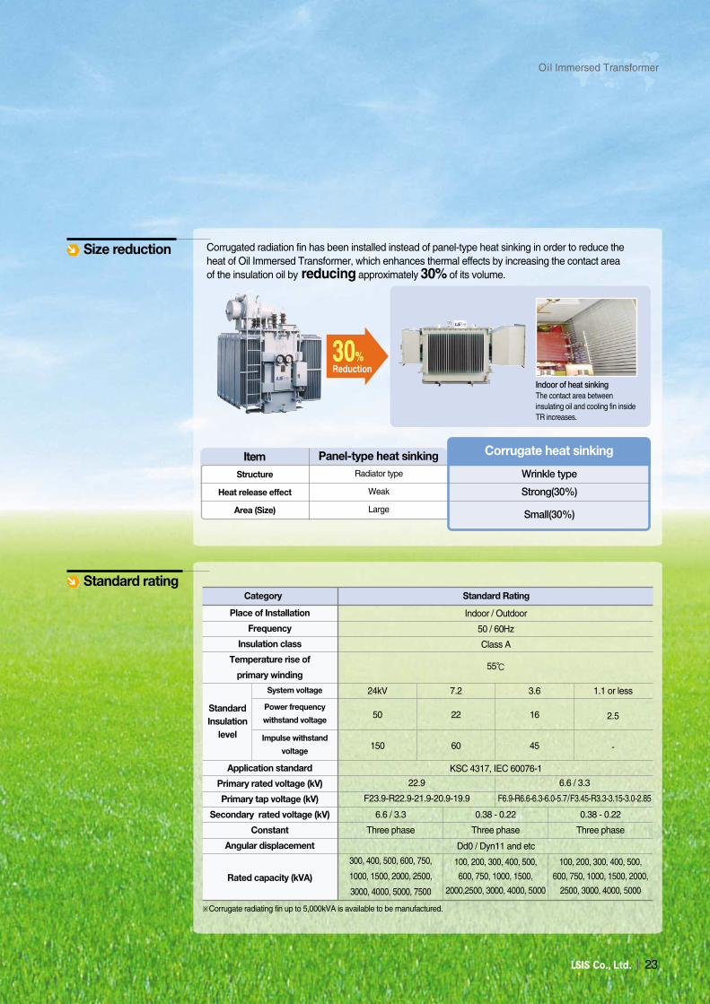
Indoor of heat sinkingThe contact area betweeninsulating oil and cooling fin insideTR increases.
30%30%Reduction
Panel-type heat sinkingItemStructure
Heat release effect
Area (Size)
Radiator type
Weak
Large
Corrugate heat sinking
Wrinkle type
Strong(30%)
Small(30%)
Corrugated radiation fin has been installed instead of panel-type heat sinking in order to reduce theheat of Oil Immersed Transformer, which enhances thermal effects by increasing the contact areaof the insulation oil by reducing approximately 30% of its volume.
Size reduction
Standard ratingCategory
Indoor / Outdoor
50 / 60Hz
Class A
55℃
KSC 4317, IEC 60076-1
Dd0 / Dyn11 and etc
24kV
50
150
22.9
F23.9-R22.9-21.9-20.9-19.9
6.6 / 3.3
Three phase
300, 400, 500, 600, 750,
1000, 1500, 2000, 2500,
3000, 4000, 5000, 7500
100, 200, 300, 400, 500,
600, 750, 1000, 1500, 2000,
2500, 3000, 4000, 5000
100, 200, 300, 400, 500,
600, 750, 1000, 1500,
2000,2500, 3000, 4000, 5000
0.38 - 0.22
Three phase
0.38 - 0.22
Three phase
6.6 / 3.3
F6.9-R6.6-6.3-6.0-5.7/F3.45-R3.3-3.15-3.0-2.85
7.2
22
60
3.6
16
45
1.1 or less
2.5
-
Standard Rating
Place of Installation
Frequency
Insulation class
Temperature rise of
primary winding
Application standard
Primary rated voltage (kV)
Primary tap voltage (kV)
Secondary rated voltage (kV)
Constant
Angular displacement
Rated capacity (kVA)
StandardInsulation
level
System voltage
Power frequency
withstand voltage
Impulse withstand
voltage
※Corrugate radiating fin up to 5,000kVA is available to be manufactured.
24II
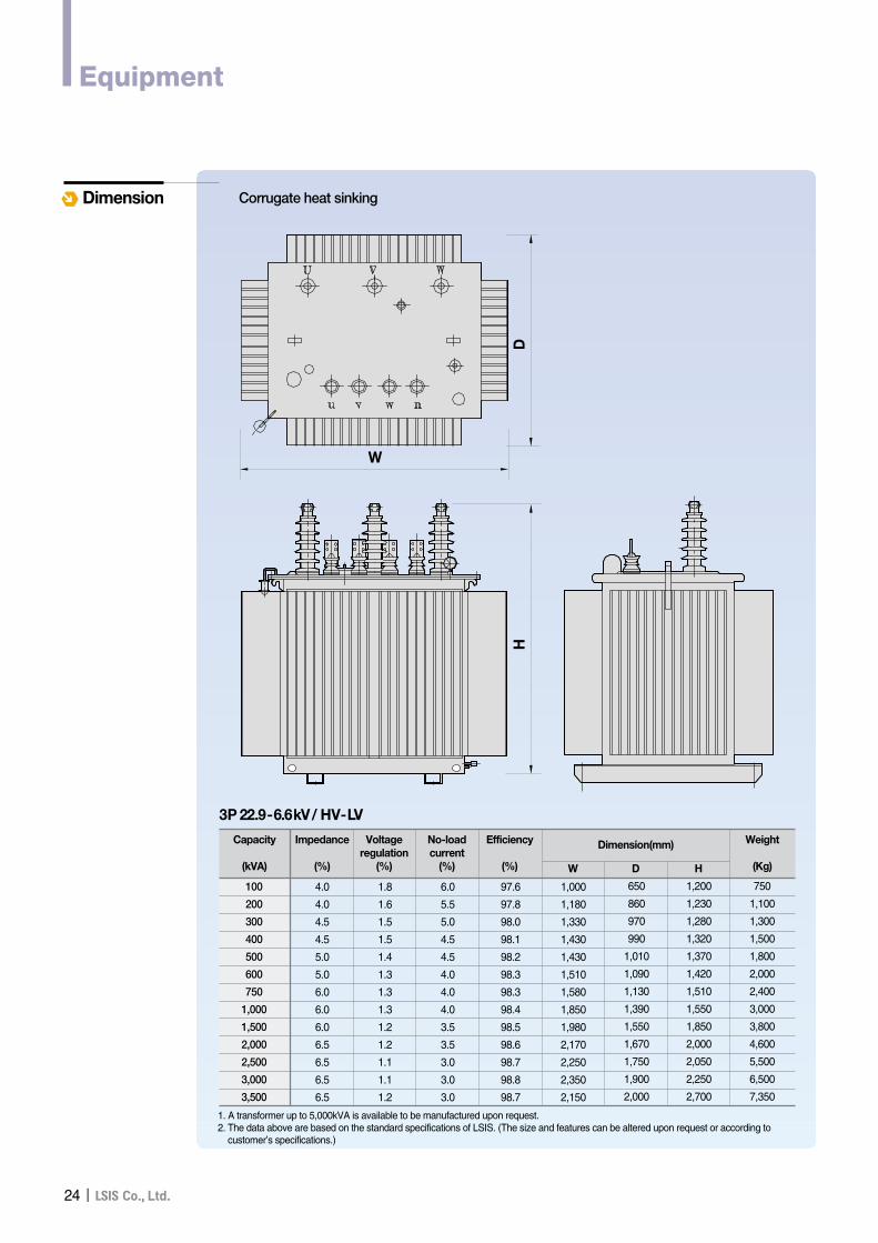
Dimension Corrugate heat sinking
D
W
H
Capacity
(kVA)
100
200
300
400
500
600
750
1,000
1,500
2,000
2,500
3,000
3,500
Impedance
(%)
4.0
4.0
4.5
4.5
5.0
5.0
6.0
6.0
6.0
6.5
6.5
6.5
6.5
750
1,100
1,300
1,500
1,800
2,000
2,400
3,000
3,800
4,600
5,500
6,500
7,350
1.8
1.6
1.5
1.5
1.4
1.3
1.3
1.3
1.2
1.2
1.1
1.1
1.2
6.0
5.5
5.0
4.5
4.5
4.0
4.0
4.0
3.5
3.5
3.0
3.0
3.0
97.6
97.8
98.0
98.1
98.2
98.3
98.3
98.4
98.5
98.6
98.7
98.8
98.7
1,000
1,180
1,330
1,430
1,430
1,510
1,580
1,850
1,980
2,170
2,250
2,350
2,150
650
860
970
990
1,010
1,090
1,130
1,390
1,550
1,670
1,750
1,900
2,000
1,200
1,230
1,280
1,320
1,370
1,420
1,510
1,550
1,850
2,000
2,050
2,250
2,700
Voltageregulation
(%)
No-loadcurrent
(%)
Efficiency
(%) W D H
Dimension(mm) Weight
(Kg)
3P 22.9-6.6kV/ HV-LV
1. A transformer up to 5,000kVA is available to be manufactured upon request.2. The data above are based on the standard specifications of LSIS. (The size and features can be altered upon request or according to
customer’s specifications.)
Equipment
II25
Oil Immersed Transformer
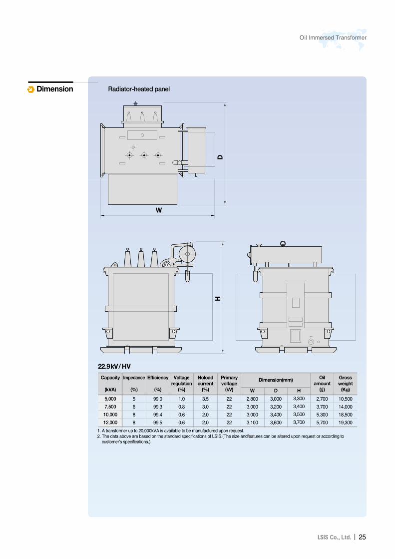
Dimension
WD
H
Radiator-heated panel
Capacity
(kVA)
5,000
7,500
10,000
12,000
D
3,000
3,200
3,400
3,600
W
2,800
3,000
3,000
3,100
H
3,300
3,400
3,500
3,700
Oilamount
(ℓ)
2,700
3,700
5,300
5,700
Primaryvoltage
(kV)
22
22
22
22
Noloadcurrent
(%)
3.5
3.0
2.0
2.0
Voltageregulation
(%)
1.0
0.8
0.6
0.6
Efficiency
(%)
99.0
99.3
99.4
99.5
Grossweight
(Kg)
10,500
14,000
18,500
19,300
22.9kV/HV
Impedance
(%)
5
6
8
8
1. A transformer up to 20,000kVA is available to be manufactured upon request.2. The data above are based on the standard specifications of LSIS.(The size andfeatures can be altered upon request or according to
customer’s specifications.)
Dimension(mm)
26II
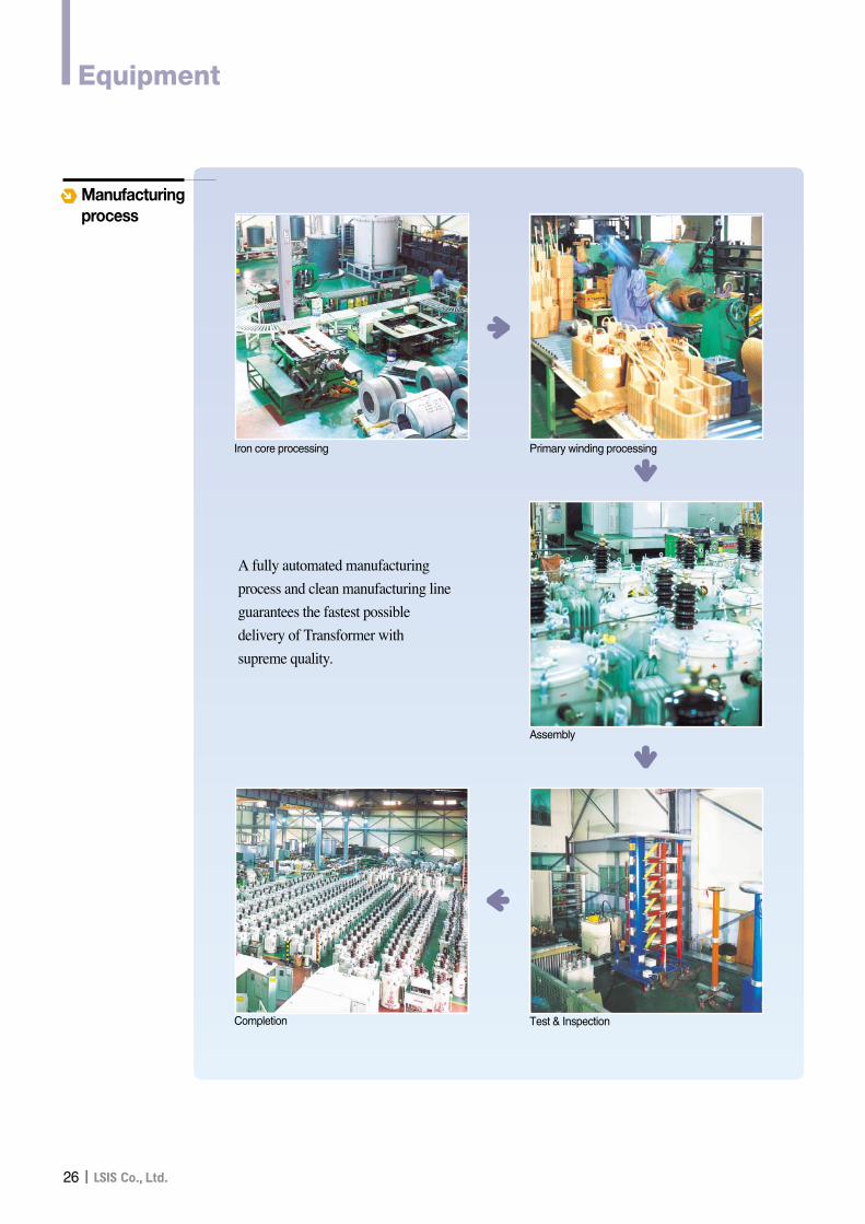
Manufacturingprocess
A fully automated manufacturing
process and clean manufacturing line
guarantees the fastest possible
delivery of Transformer with
supreme quality.
�
�Iron core processing Primary winding processing
�Assembly
�
Completion Test & Inspection
Equipment
II27
Oil Immersed Transformer
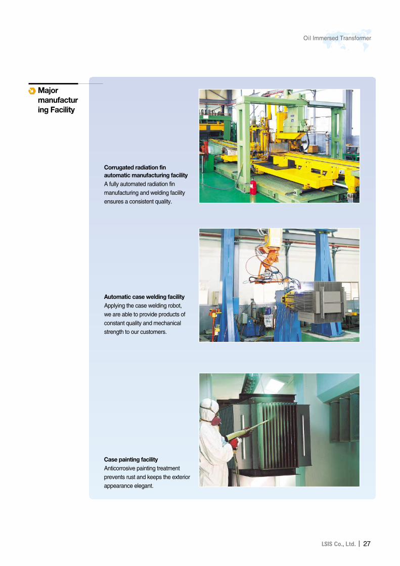
Majormanufacturing Facility
Corrugated radiation finautomatic manufacturing facilityA fully automated radiation finmanufacturing and welding facilityensures a consistent quality.
Automatic case welding facilityApplying the case welding robot, we are able to provide products ofconstant quality and mechanicalstrength to our customers.
Case painting facilityAnticorrosive painting treatmentprevents rust and keeps the exteriorappearance elegant.
28II
Equipment
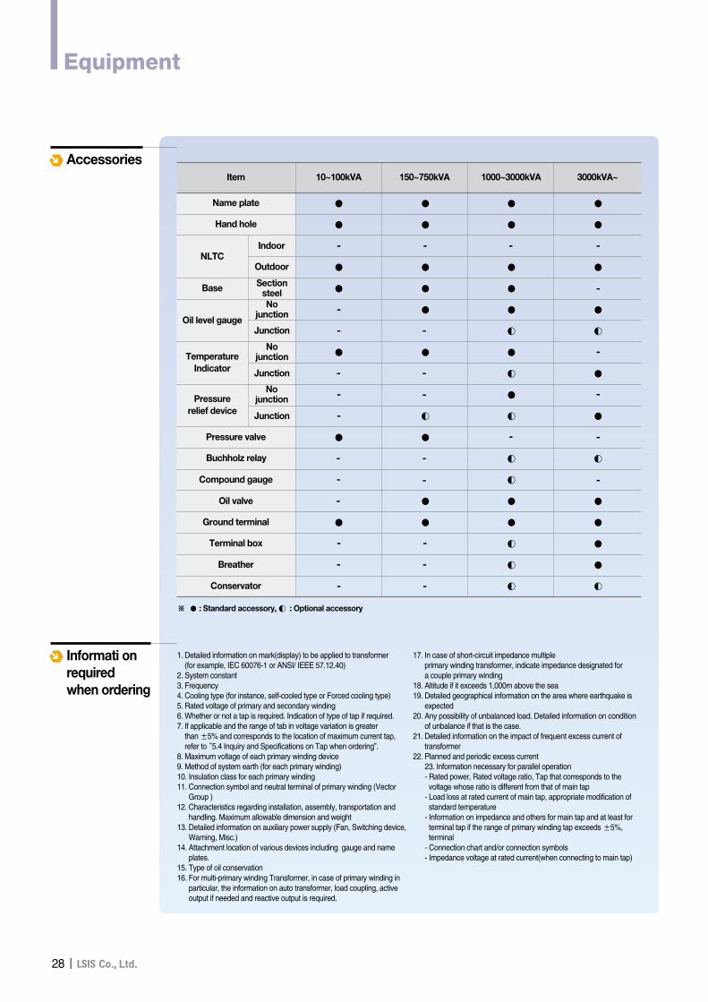
AccessoriesItem
Name plate
Hand hole
-
● ● ●
●
●
●
◐
●
●
◐
●
●
●
●
◐
●
●
●
●
●
●
●
◐
◐
◐
◐
◐
●
●
◐
◐
◐
●
●
●
●
●
●
●
●
◐
●
●
●
●
●
●
- - -
-
-
-
-
-
-
- -
- -
--
-
-
- -
-
--
-
-
-
-
-
-
NLTCIndoor
Outdoor
Oil level gauge
Nojunction
Junction
TemperatureIndicator
Nojunction
Junction
Pressure relief device
Nojunction
Junction
SectionsteelBase
Pressure valve
Buchholz relay
Compound gauge
Oil valve
Ground terminal
Terminal box
Breather
Conservator
※ ● : Standard accessory, ◐ : Optional accessory
10~100kVA 150~750kVA 1000~3000kVA 3000kVA~
Informati onrequired when ordering
1. Detailed information on mark(display) to be applied to transformer(for example, IEC 60076-1 or ANSI/ IEEE 57.12.40)
2. System constant3. Frequency4. Cooling type (for instance, self-cooled type or Forced cooling type)5. Rated voltage of primary and secondary winding6. Whether or not a tap is required. Indication of type of tap if required.7. If applicable and the range of tab in voltage variation is greater
than ±5% and corresponds to the location of maximum current tap,refer to “5.4 Inquiry and Specifications on Tap when ordering”.
8. Maximum voltage of each primary winding device9. Method of system earth (for each primary winding)10. Insulation class for each primary winding11. Connection symbol and neutral terminal of primary winding (Vector
Group )12. Characteristics regarding installation, assembly, transportation and
handling. Maximum allowable dimension and weight13. Detailed information on auxiliary power supply (Fan, Switching device,
Warning, Misc.)14. Attachment location of various devices including gauge and name
plates.15. Type of oil conservation16. For multi-primary winding Transformer, in case of primary winding in
particular, the information on auto transformer, load coupling, activeoutput if needed and reactive output is required.
17. In case of short-circuit impedance multipleprimary winding transformer, indicate impedance designated fora couple primary winding
18. Altitude if it exceeds 1,000m above the sea19. Detailed geographical information on the area where earthquake is
expected20. Any possibility of unbalanced load. Detailed information on condition
of unbalance if that is the case.21. Detailed information on the impact of frequent excess current of
transformer22. Planned and periodic excess current
23. Information necessary for parallel operation - Rated power, Rated voltage ratio, Tap that corresponds to thevoltage whose ratio is different from that of main tap
- Load loss at rated current of main tap, appropriate modification ofstandard temperature
- Information on impedance and others for main tap and at least forterminal tap if the range of primary winding tap exceeds ±5%,terminal
- Connection chart and/or connection symbols- Impedance voltage at rated current(when connecting to main tap)
II29
Oil Immersed Transformer
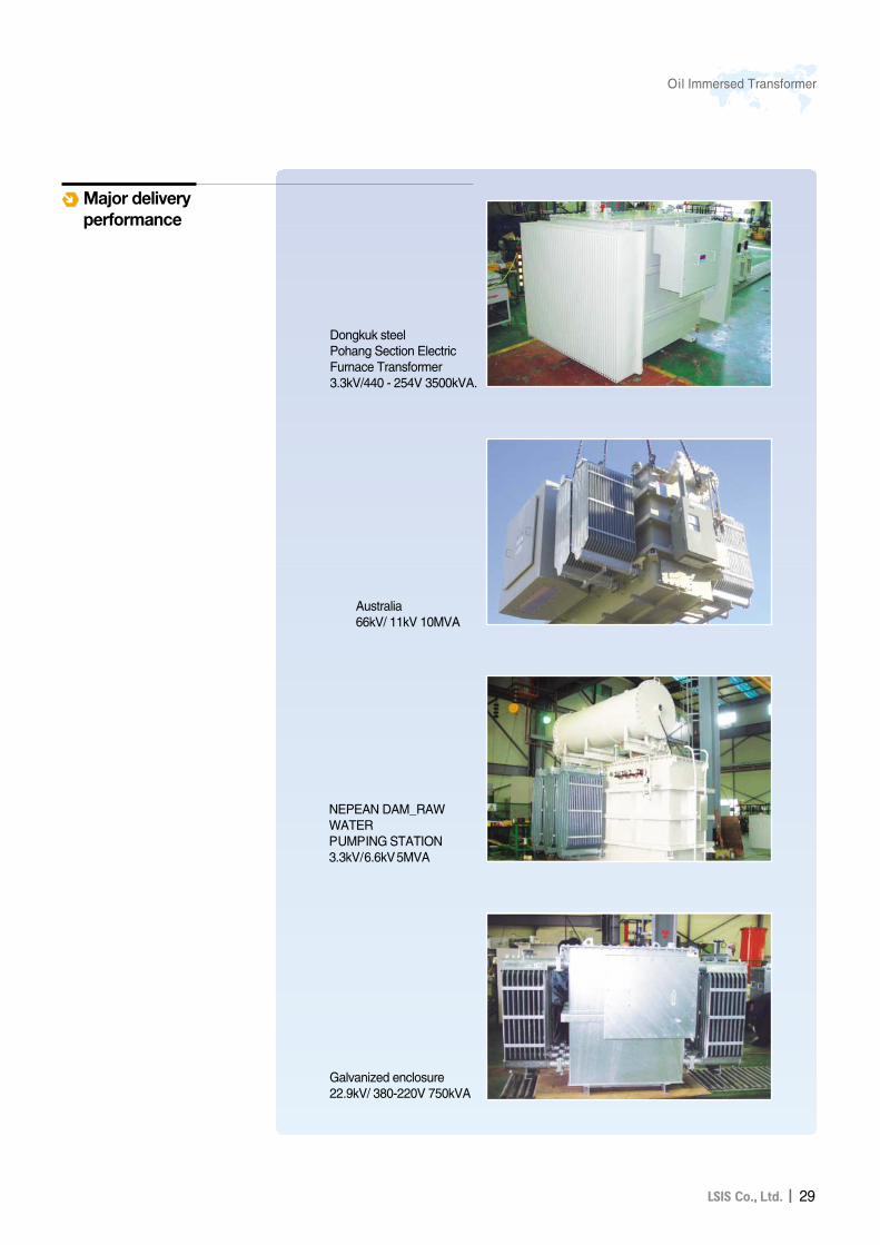
Dongkuk steelPohang Section ElectricFurnace Transformer3.3kV/440 - 254V 3500kVA.
Australia66kV/ 11kV 10MVA
NEPEAN DAM_RAWWATERPUMPING STATION3.3kV/6.6kV5MVA
Galvanized enclosure22.9kV/ 380-220V 750kVA
Major deliveryperformance

30II
Memo
II31
Oil Immersed Transformer
�For your safety, please read user's manual thoroughly before operating.
�Contact the nearest authorized service facility for examination, repair, or adjustment.
�Please contact qualified service technician when you need maintenance.Do not disassemble or repair by yourself!
�Any maintenance and inspection shall be performed by the personnel having expertise concerned.Safety Instructions
www.lsis.biz
�LSIS (Middle East) FZE ��Dubai, U.A.E. Address: LOB 19 JAFZA VIEW TOWER Room 205, Jebel Ali Freezone P.O. Box 114216, Dubai, United Arab EmiratesTel: 971-4-886 5360 Fax: 971-4-886-5361 e-mail: [email protected]
�Dalian LSIS Co., Ltd. ��Dalian, ChinaAddress: No.15, Liaohexi 3-Road, Economic and Technical Development zone, Dalian 116600, ChinaTel: 86-411-8273-7777 Fax: 86-411-8730-7560 e-mail: [email protected]
�LSIS (Wuxi) Co., Ltd. ��Wuxi, ChinaAddress: 102-A , National High & New Tech Industrial Development Area, Wuxi, Jiangsu, 214028, P.R.ChinaTel: 86-510-8534-6666 Fax: 86-510-522-4078 e-mail: [email protected]
�LSIS-VINA Co., Ltd. ��Hanoi, VietnamAddress: Nguyen Khe - Dong Anh - Ha Noi - Viet NamTel: 84-4-882-0222 Fax: 84-4-882-0220 e-mail: [email protected]
�LSIS-VINA Co., Ltd. ��Hochiminh , VietnamAddress: 41 Nguyen Thi Minh Khai Str. Yoco Bldg 4th Floor, Hochiminh City, VietnamTel: 84-8-3822-7941 Fax: 84-8-3822-7942 e-mail: [email protected]
�LSIS Tokyo Office ��Tokyo, JapanAddress : 16th, Higashi-Kan, Akasaka Twin Tower, 2-17-22, Akasaka, Minato-ku, Tokyo, JapanTel: 81-3-3582-9128 Fax: 81-3-3582-2667 e-mail: [email protected]
�LSIS Shanghai Office ��Shanghai, ChinaAddress: Room E-G, 12th Floor Huamin Empire Plaza, No.726, West Yan'an Road Shanghai 200050, P.R. ChinaTel: 86-21-5237-9977 (609) Fax: 89-21-5237-7191 e-mail: [email protected]
�LSIS Beijing Office ��Beijing, ChinaAddress: B-Tower 17FL.Beijing Global Trade Center B/D. No.36, BeiSanHuanDong-Lu, DongCheng-District,Beijing 100013, P.R. ChinaTel: 86-10-5825-6025,7 Fax: 86-10-5825-6026 e-mail: [email protected]
�LSIS Guangzhou Office ��Guangzhou, ChinaAddress: Room 1403,14F,New Poly Tower,2 Zhongshan Liu Road,Guangzhou, P.R. ChinaTel: 86-20-8326-6764 Fax: 86-20-8326-6287 e-mail: [email protected]
�LSIS Chengdu Office ��Chengdu, ChinaAddress: Room 1701 17Floor, huanminhanjun internationnal Building, No1 Fuxing Road Chengdu, 610041, P.R. ChinaTel: 86-28-8670-3101 Fax: 86-28-8670-3203 e-mail: [email protected]
�LSIS Qingdao Office ��Qingdao, ChinaAddress: 7B40,Haixin Guangchang Shenye Building B, No.9, Shandong Road Qingdao 26600, P.R. ChinaTel: 86-532-8501-6568 Fax: 86-532-583-3793 e-mail: [email protected]
� HEAD OFFICELS Tower, 1026-6 Hogye-dong, Dongan-gu,
Anyang-si, Gyeonggi-do 431-848, Korea
Tel. (82-2)2034-4910/4875/4865
Fax. (82-2)780-0382
e-mail. [email protected], [email protected], [email protected]
http://www.lsis.biz
�Global Network
Specifications in this catalog are subject to change without notice due to continuous product development and improvement.
2011. 05 Cast Resin Transformers / Oil Immersed Transformer (E) 2009. 04/(01) 2011. 05 Printed in Korea STAFF
ⓒ 2009.4 LSIS Co.,Ltd. All rights reserved.