Embed Size (px)
Citation preview
TECHNICALPROCEDUREINTRAAX® SUSPENSION SYSTEMS
SUBJECT: Installation ProceduresLIT NO: L341DATE: January 2000 REVISION: C
TABLE OF CONTENTS
INTRODUCTION . . . . . . . . . . . . . . . . . . . . . . . . . . . . . . . . . . . . . . . . . . . . . . . . . . . . . . . . . . . . . . . . . 2
PRE-INSTALLATION PROCEDURES . . . . . . . . . . . . . . . . . . . . . . . . . . . . . . . . . . . . . . . . . . . . . . . . . . . . . 3
SUSPENSION ASSEMBLY INSTALLATION . . . . . . . . . . . . . . . . . . . . . . . . . . . . . . . . . . . . . . . . . . . . . . . . . 4
RECOMMENDED WELDING PROCEDURES . . . . . . . . . . . . . . . . . . . . . . . . . . . . . . . . . . . . . . . . . . . . . . . .7
AIR CONTROLS INSTALLATION . . . . . . . . . . . . . . . . . . . . . . . . . . . . . . . . . . . . . . . . . . . . . . . . . . . . . . 12
DESIGNED RIDE HEIGHT MEASUREMENT . . . . . . . . . . . . . . . . . . . . . . . . . . . . . . . . . . . . . . . . . . . . . . . 12
HEIGHT CONTROL VALVE . . . . . . . . . . . . . . . . . . . . . . . . . . . . . . . . . . . . . . . . . . . . . . . . . . . . . . . . . . 14
WHEEL BEARING ADJUSTMENT . . . . . . . . . . . . . . . . . . . . . . . . . . . . . . . . . . . . . . . . . . . . . . . . . . . . . 16
CONMET PRESET™ HUB PROCEDURES . . . . . . . . . . . . . . . . . . . . . . . . . . . . . . . . . . . . . . . . . . . . . . . . .17
AXLE ALIGNMENT — QUIK-ALIGN® . . . . . . . . . . . . . . . . . . . . . . . . . . . . . . . . . . . . . . . . . . . . . . . . . . .18
HK SLIDER SYSTEM INSTALLATION . . . . . . . . . . . . . . . . . . . . . . . . . . . . . . . . . . . . . . . . . . . . . . . . . . .20
FINAL INSPECTION . . . . . . . . . . . . . . . . . . . . . . . . . . . . . . . . . . . . . . . . . . . . . . . . . . . . . . . . . . . . . .25
APPENDIX . . . . . . . . . . . . . . . . . . . . . . . . . . . . . . . . . . . . . . . . . . . . . . . . . . . . . . . . . . . . . . . . . . . .26
INTRAAX® INSTALLATION PROCEDURES
2
INTRODUCTIONThe following instructions are intended for use with theHendrickson INTRAAX® Air Ride Suspension.For instructions concerning other suspension models,contact the Hendrickson Trailer Suspension SystemsTechnical Service Department at (330)456-7288.
NOTE: Always read the entire installation instructionsthoroughly before proceeding with a suspensioninstallation.
It is very important that the proper suspension is chosen forthe trailer application. The following criteria must be considered when selecting a suspension:
• required capacity• loaded frame-to-ground measurement• axle travel• axle spacing
For additional information concerning suspensionselection, contact the Hendrickson Trailer SuspensionSystems Customer Service Department at (330) 456-7288.
CAUTION: The INTRAAX suspension system, aswith all air suspension systems, mustbe installed with the proper amount offrame-to-ground clearance to ensuretrouble-free operation. If there is toomuch ground clearance, thesuspension will not carry its share ofthe load. Too little ground clearancemay damage the suspension or othervehicle components.
A correct installation must result in aLOADED suspension ride height that iswithin the range specified on thesuspension assembly drawing.
The trailer manufacturer should beconsulted before making any changesto the vehicle’s frame. Typically,cutting or altering the trailer’s frame orside rail is not permitted and mayaffect the manufacturer’s warrantycoverage.
SPECIAL NOTESDefective or incorrect components are to be returned to Hendrickson, which will supply replacements for the components in question per product warranty conditions.
It is the responsibility of the installer to determine thecorrect location of the suspension in order to providethe proper trailer load distribution. The load carried byeach axle must not exceed the rated capacity of thecomponents involved.
No welding of any of the suspension components ispermitted, except where specified by Hendrickson.
No welding of the axle assembly or axle components ispermitted.
No alteration of any of the suspension components ispermitted.
Any installation deviations must be approved, in writing, by Hendrickson Trailer Suspension SystemsProduct Engineering Department at (330) 456-7288.
It is the responsibility of the installer to ensure thatproper clearances exist between:
• Tires— Laterally— Vertically— Fore and aft
• Air springs when they are at their maximum diameter (refer to suspension assembly drawing for specifications).
3
INTRAAX® INSTALLATION PROCEDURES
PRE-INSTALLATION PROCEDURESREQUIRED SUPPLIESThe following equipment and materials are neededwhen installing a Hendrickson INTRAAX suspension:
1. Welding equipment and supplies. (SeeRECOMMENDED WELDING PROCEDURES.)
2. Torque wrench (capability of 600 ft-lbs).
3. Tape measure or scale(s) and machinist square.
4. Trammel bar.
5. Crane or lifting capability.
6. Hammer or center punch (for bolt-on).
7. Compressed air supply.
8. Air impact gun (capability of 600 ft-lbs).
9. Air fittings, tubing and associated tools.
10. 1/2" drive breaker bar.
11. Socket set and wrenches, including the followingsizes:• 3/8"• 9/16"• 3/4"• 11/8"• 11/4" deep well socket• 15/16" deep well socket• 17/16" wrench• 1" drive, E-20 socket
(Hendrickson P/N A-24536)
12. Suspension assembly drawing and plumbingschematic supplied by Hendrickson.
13. Wheel chocks.
14. Frame jacks or supports.
PRE-INSTALLATION CHECKLISTBefore beginning the installation:
1. Check that the new suspension matches thespecifications provided by your Production orEngineering Department.
2. Verify that the vehicle will have the proper loaddistribution after installation.
3. Verify that the actual trailer crossmember(s)locations correspond with the locations specifiedon the suspension assembly drawing.
4. Confirm that the components listed on thesuspension assembly drawing have been providedin sufficient quantities. Contact the HendricksonTrailer Suspension Systems Customer ServiceDepartment if any missing or damagedcomponents are found.
INTRAAX® INSTALLATION PROCEDURES
4
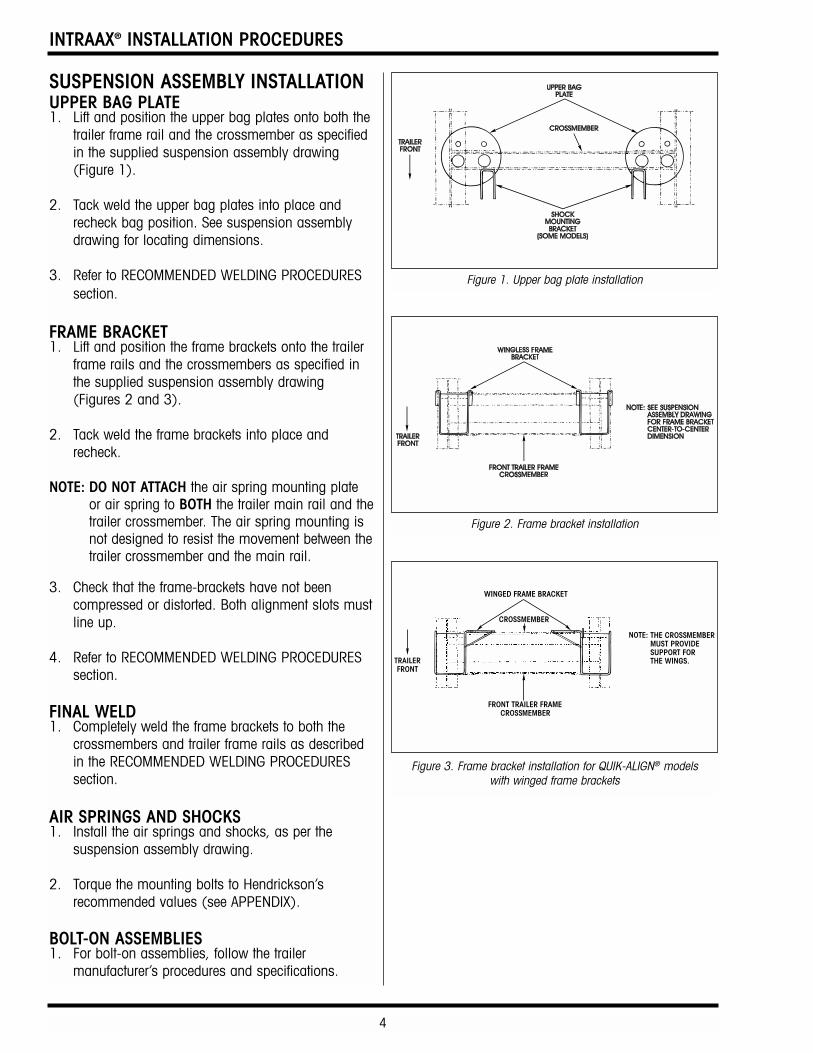
SUSPENSION ASSEMBLY INSTALLATIONUPPER BAG PLATE1. Lift and position the upper bag plates onto both the
trailer frame rail and the crossmember as specifiedin the supplied suspension assembly drawing(Figure 1).
2. Tack weld the upper bag plates into place andrecheck bag position. See suspension assemblydrawing for locating dimensions.
3. Refer to RECOMMENDED WELDING PROCEDURESsection.
FRAME BRACKET1. Lift and position the frame brackets onto the trailer
frame rails and the crossmembers as specified inthe supplied suspension assembly drawing(Figures 2 and 3).
2. Tack weld the frame brackets into place andrecheck.
NOTE: DO NOT ATTACH the air spring mounting plateor air spring to BOTH the trailer main rail and thetrailer crossmember. The air spring mounting isnot designed to resist the movement between thetrailer crossmember and the main rail.
3. Check that the frame-brackets have not beencompressed or distorted. Both alignment slots mustline up.
4. Refer to RECOMMENDED WELDING PROCEDURESsection.
FINAL WELD1. Completely weld the frame brackets to both the
crossmembers and trailer frame rails as describedin the RECOMMENDED WELDING PROCEDURESsection.
AIR SPRINGS AND SHOCKS1. Install the air springs and shocks, as per the
suspension assembly drawing.
2. Torque the mounting bolts to Hendrickson’srecommended values (see APPENDIX).
BOLT-ON ASSEMBLIES1. For bolt-on assemblies, follow the trailer
manufacturer’s procedures and specifications.
Figure 1. Upper bag plate installation
Figure 2. Frame bracket installation
Figure 3. Frame bracket installation for QUIK-ALIGN® models with winged frame brackets
5
INTRAAX® INSTALLATION PROCEDURES
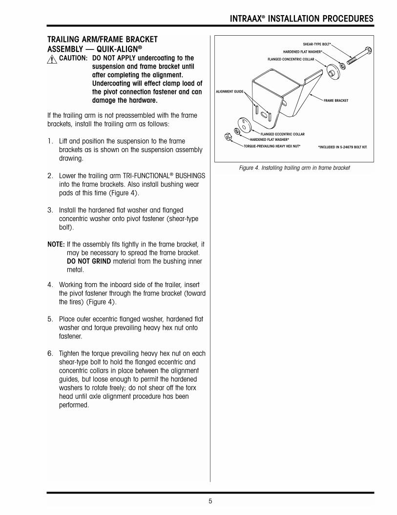
TRAILING ARM/FRAME BRACKET ASSEMBLY — QUIK-ALIGN®
CAUTION: DO NOT APPLY undercoating to thesuspension and frame bracket untilafter completing the alignment.Undercoating will effect clamp load ofthe pivot connection fastener and candamage the hardware.
If the trailing arm is not preassembled with the framebrackets, install the trailing arm as follows:
1. Lift and position the suspension to the framebrackets as is shown on the suspension assemblydrawing.
2. Lower the trailing arm TRI-FUNCTIONAL® BUSHINGSinto the frame brackets. Also install bushing wearpads at this time (Figure 4).
3. Install the hardened flat washer and flangedconcentric washer onto pivot fastener (shear-typebolt).
NOTE: If the assembly fits tightly in the frame bracket, itmay be necessary to spread the frame bracket.DO NOT GRIND material from the bushing innermetal.
4. Working from the inboard side of the trailer, insertthe pivot fastener through the frame bracket (towardthe tires) (Figure 4).
5. Place outer eccentric flanged washer, hardened flatwasher and torque prevailing heavy hex nut ontofastener.
6. Tighten the torque prevailing heavy hex nut on eachshear-type bolt to hold the flanged eccentric andconcentric collars in place between the alignmentguides, but loose enough to permit the hardenedwashers to rotate freely; do not shear off the torxhead until axle alignment procedure has beenperformed.
Figure 4. Installing trailing arm in frame bracket
INTRAAX® INSTALLATION PROCEDURES
6
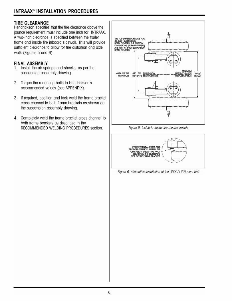
TIRE CLEARANCEHendrickson specifies that the tire clearance above thejounce requirement must include one inch for INTRAAX.A two-inch clearance is specified between the trailerframe and inside tire inboard sidewall. This will providesufficient clearance to allow for tire distortion and axlewalk (Figures 5 and 6).
FINAL ASSEMBLY1. Install the air springs and shocks, as per the
suspension assembly drawing.
2. Torque the mounting bolts to Hendrickson’srecommended values (see APPENDIX).
3. If required, position and tack weld the frame bracketcross channel to both frame brackets as shown onthe suspension assembly drawing.
4. Completely weld the frame bracket cross channel toboth frame brackets as described in theRECOMMENDED WELDING PROCEDURES section. Figure 5. Inside-to-inside tire measurements
Figure 6. Alternative installation of the QUIK-ALIGN pivot bolt
7
INTRAAX® INSTALLATION PROCEDURES
RECOMMENDED WELDING PROCEDURESWARNING: IF THESE PROCEDURES AND
SPECIFICATIONS ARE NOT FOLLOWED,DAMAGE TO THE AXLE ORSUSPENSION COULD RESULT. THERESULTING AXLE OR SUSPENSIONDAMAGE COULD CAUSE ANACCIDENT, PROPERTY DAMAGE,AND/OR SERIOUS INJURY.
WELDING PARAMETERSNOTE: A welder qualified in 2G position per ANSI/AWS
D1.1-94 Section 5 Part C “Welder Qualification”must perform the welding.
NOTE: The specification shown below is for horizontal(2F) positioning.
1. Suspension components and their mating partsmust be at a minimum temperature of 60ºF(15.5ºC) and free from moisture, dirt, scale, paintand grease.
2. All welds must be performed in a flat, or horizontal,position.
3. Achieve spray arc transfer with the followingwelding parameters:
• StandardElectrode: AWS E-7018 (Oven Dried)
— .125 DIA. 120-140 AMPS D.C.ELECTRODE POSITIVE
— .156 DIA. 120-160 AMPS D.C. ELECTRODE POSITIVE
• Standard Wire: AWS ER-70S-6 — .045 DIA.
(i.e., LA-56 or NS-115)
• Optional Wire: AWS ER-70S-3 — .045 DIA.
(i.e., LA-50 or NS-101)
• Volts: 26-30 DCRP
• Current: 275-325 AMPS
• Wire Feed Speed: 380-420 IPM
• Electrode Extension: 3/4"-1"
• Gas: 86% Ar 14% CO2
at 30 to 35 CFH
NOTE: Any deviation from these welding parametersmust be approved by Hendrickson TrailerSuspension Systems in writing.
INTRAAX® INSTALLATION PROCEDURES
8
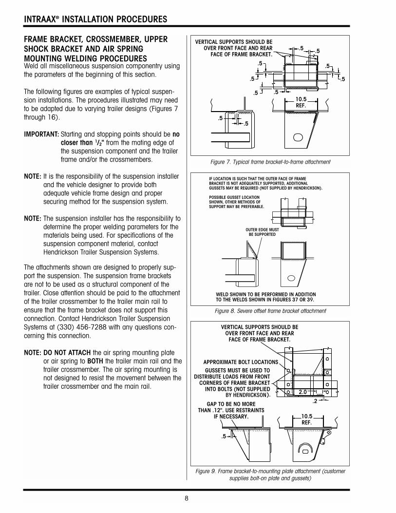
FRAME BRACKET, CROSSMEMBER, UPPERSHOCK BRACKET AND AIR SPRINGMOUNTING WELDING PROCEDURESWeld all miscellaneous suspension componentry usingthe parameters at the beginning of this section.
The following figures are examples of typical suspen-sion installations. The procedures illustrated may needto be adapted due to varying trailer designs (Figures 7through 16).
IMPORTANT: Starting and stopping points should be nocloser than 1/2" from the mating edge ofthe suspension component and the trailerframe and/or the crossmembers.
NOTE: It is the responsibility of the suspension installerand the vehicle designer to provide bothadequate vehicle frame design and propersecuring method for the suspension system.
NOTE: The suspension installer has the responsibility todetermine the proper welding parameters for thematerials being used. For specifications of thesuspension component material, contactHendrickson Trailer Suspension Systems.
The attachments shown are designed to properly sup-port the suspension. The suspension frame bracketsare not to be used as a structural component of thetrailer. Close attention should be paid to the attachmentof the trailer crossmember to the trailer main rail toensure that the frame bracket does not support thisconnection. Contact Hendrickson Trailer SuspensionSystems at (330) 456-7288 with any questions con-cerning this connection.
NOTE: DO NOT ATTACH the air spring mounting plateor air spring to BOTH the trailer main rail and thetrailer crossmember. The air spring mounting isnot designed to resist the movement between thetrailer crossmember and the main rail.
Figure 7. Typical frame bracket-to-frame attachment
Figure 8. Severe offset frame bracket attachment
Figure 9. Frame bracket-to-mounting plate attachment (customersupplies bolt-on plate and gussets)
9
INTRAAX® INSTALLATION PROCEDURES
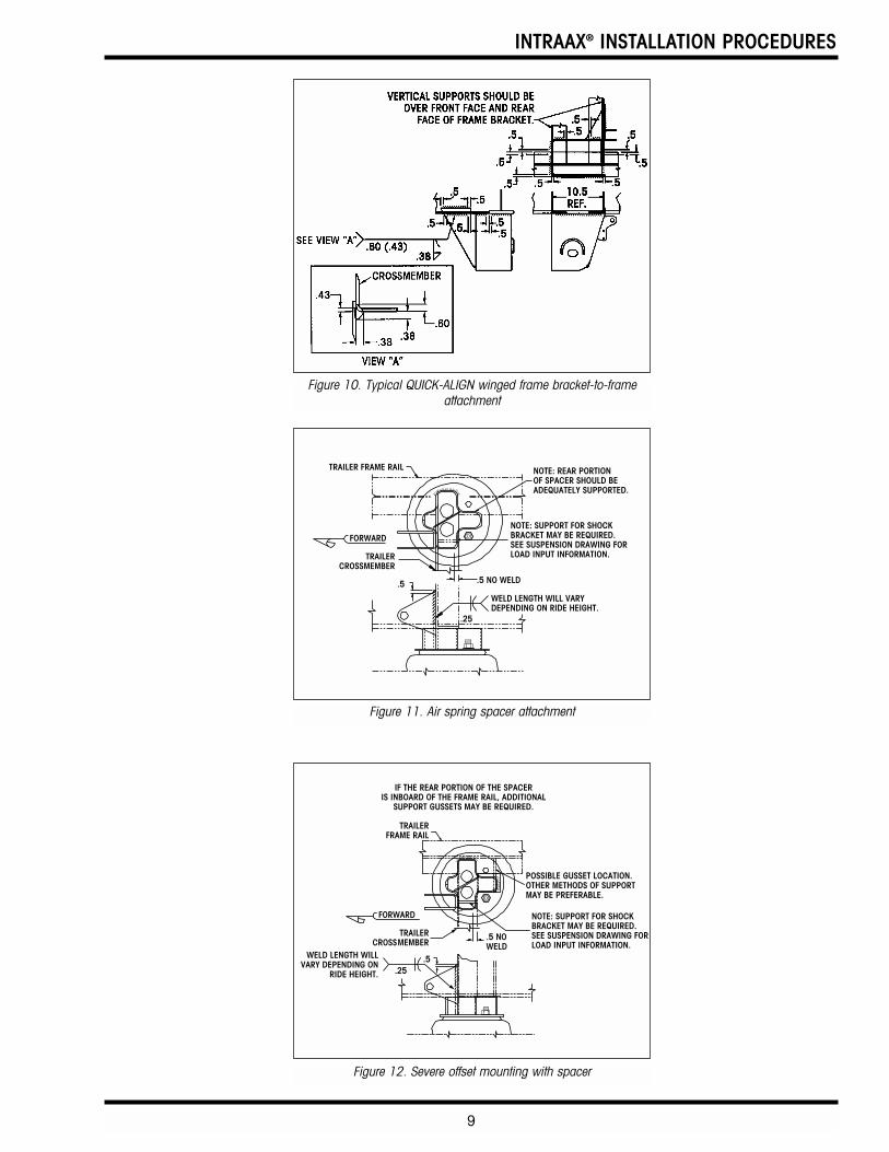
Figure 11. Air spring spacer attachment
Figure 12. Severe offset mounting with spacer
Figure 10. Typical QUICK-ALIGN winged frame bracket-to-frameattachment
INTRAAX® INSTALLATION PROCEDURES
10
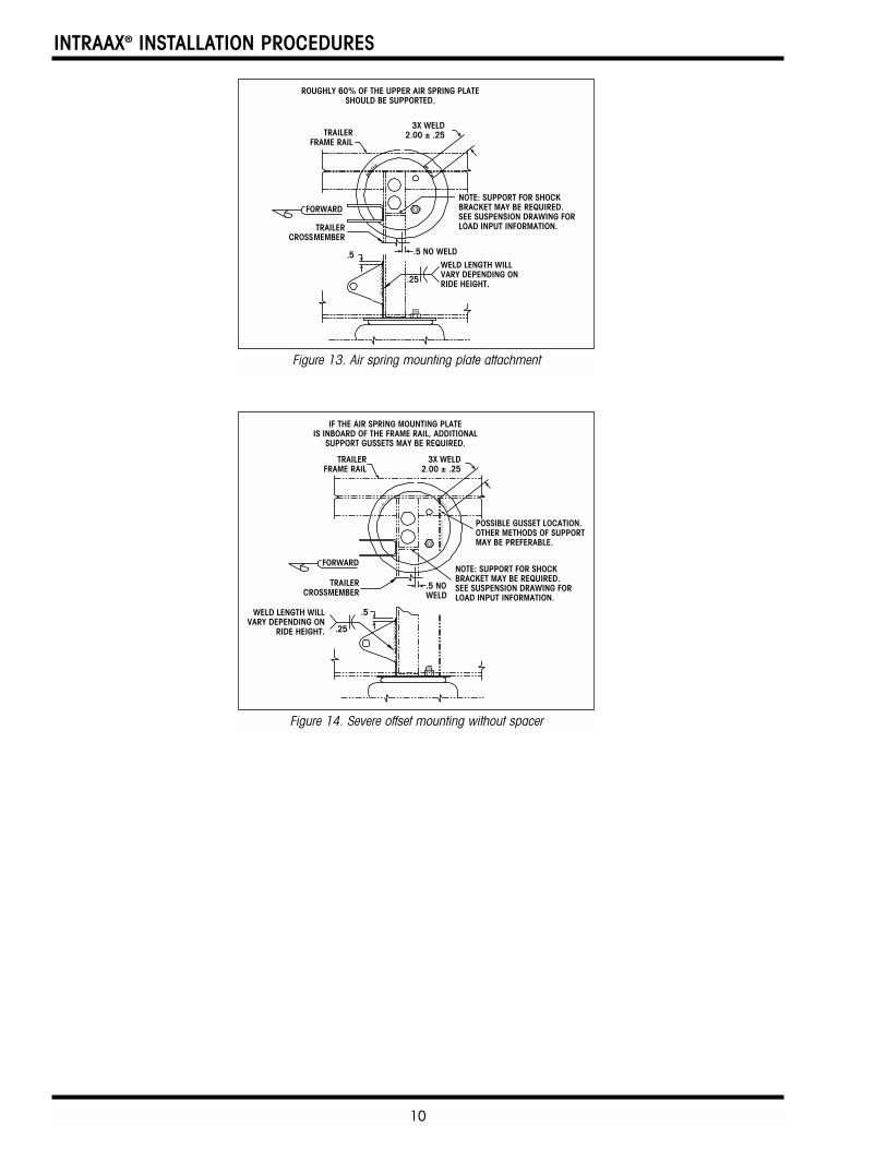
Figure 13. Air spring mounting plate attachment
Figure 14. Severe offset mounting without spacer
11
INTRAAX® INSTALLATION PROCEDURES
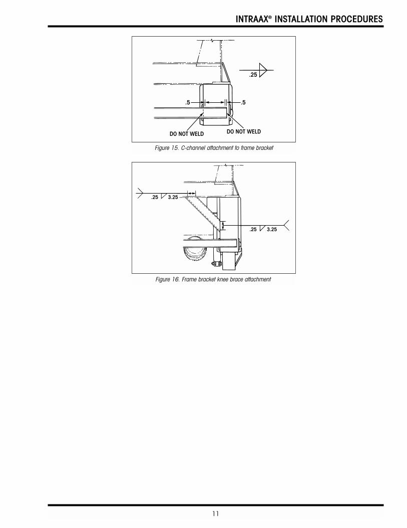
Figure 16. Frame bracket knee brace attachment
Figure 15. C-channel attachment to frame bracket
INTRAAX® INSTALLATION PROCEDURES
12
AIR CONTROLS INSTALLATIONHendrickson offers a variety of air control systems fortrailer air suspensions. The installation procedures varydepending on the specified air control kit for the trailerand the trailer’s air system. A diagram showing thecomponent and air line arrangement is supplied witheach kit. Review the supplied suspension assemblydrawing for additional notes, such as height controlvalve arm length. Fittings and air lines are not provided.Contact Hendrickson Trailer Suspension SystemsTechnical Service Department at (330) 456-7288 withany questions regarding installation of air controls.
The following notes apply to all Hendrickson Trailer aircontrol kits:
1. Do not add lubrication to air system.
2. All connections must be leak proof.
3. Avoid sharp bends in the air lines that can restrictairflow and provide adequate excess air line whenconnecting to moving parts.
4. D.O.T.-approved tubing and fittings are to befurnished by the customer.
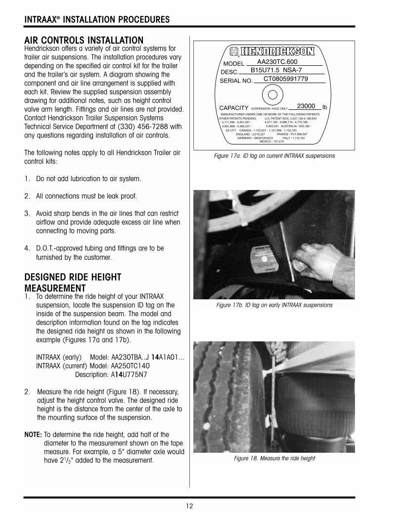
DESIGNED RIDE HEIGHTMEASUREMENT1. To determine the ride height of your INTRAAX
suspension, locate the suspension ID tag on theinside of the suspension beam. The model anddescription information found on the tag indicatesthe designed ride height as shown in the followingexample (Figures 17a and 17b).
INTRAAX (early) Model: AA230TBA..J 14A1A01...INTRAAX (current) Model: AA250TC140
Description: A14U775N7
2. Measure the ride height (Figure 18). If necessary,adjust the height control valve. The designed rideheight is the distance from the center of the axle tothe mounting surface of the suspension.
NOTE: To determine the ride height, add half of thediameter to the measurement shown on the tapemeasure. For example, a 5" diameter axle wouldhave 21/2" added to the measurement.
Figure 17b. ID tag on early INTRAAX suspensions
Figure 17a. ID tag on current INTRAAX suspensions
Figure 18. Measure the ride height
13
INTRAAX® INSTALLATION PROCEDURES
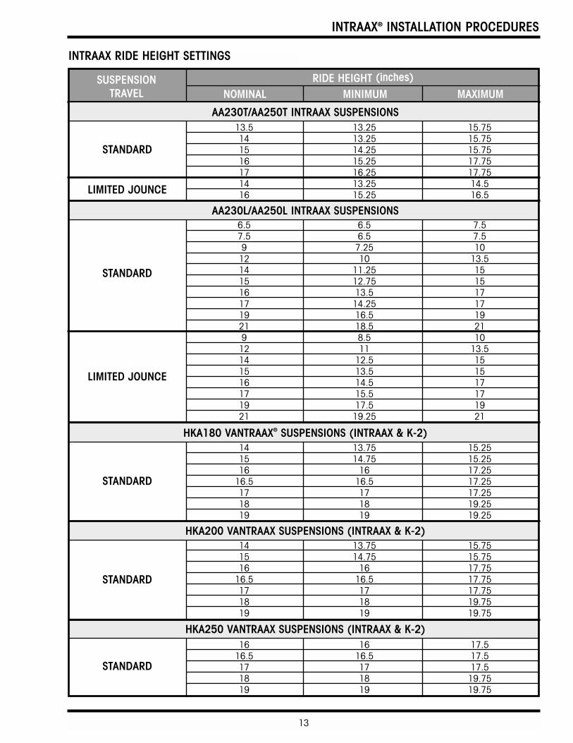
INTRAAX RIDE HEIGHT SETTINGS
SUSPENSION TRAVEL
RIDE HEIGHT (inches)
NOMINAL MINIMUM MAXIMUM
AA230L/AA250L INTRAAX SUSPENSIONS
HKA180 VANTRAAX® SUSPENSIONS (INTRAAX & K-2)
HKA200 VANTRAAX SUSPENSIONS (INTRAAX & K-2)
HKA250 VANTRAAX SUSPENSIONS (INTRAAX & K-2)
STANDARD
LIMITED JOUNCE
13.5 13.25 15.7514 13.25 15.7515 14.25 15.7516 15.25 17.7517 16.25 17.7514 13.25 14.516 15.25 16.5
14 13.75 15.2515 14.75 15.2516 16 17.25
16.5 16.5 17.2517 17 17.2518 18 19.2519 19 19.25
14 13.75 15.7515 14.75 15.7516 16 17.75
16.5 16.5 17.7517 17 17.7518 18 19.7519 19 19.75
16 16 17.516.5 16.5 17.517 17 17.518 18 19.7519 19 19.75
6.5 6.5 7.57.5 6.5 7.59 7.25 1012 10 13.514 11.25 1515 12.75 1516 13.5 1717 14.25 1719 16.5 1921 18.5 219 8.5 1012 11 13.514 12.5 1515 13.5 1516 14.5 1717 15.5 1719 17.5 1921 19.25 21
STANDARD
STANDARD
STANDARD
STANDARD
LIMITED JOUNCE
AA230T/AA250T INTRAAX SUSPENSIONS
INTRAAX® INSTALLATION PROCEDURES
14
HEIGHT CONTROL VALVETHEORY OF OPERATIONThe height control valve is the part of the air suspen-sion system that imports and exports air to and fromair springs. Our height control valve maintains a con-stant static design height and does not respond to shortduration dynamic changes in axle position.
Hendrickson Trailer Air Suspension Systems need onlyone height control valve per trailer, regardless of thenumber of axles. The reason is our own patenteddesign that uses the TRI-FUNCTIONAL BUSHING inconjunction with a rigid axle connection. The beamsand axle act like a tension bar which, in turn, gives thesuspension its roll stability.
Hendrickson generally recommends the height controlvalve be mounted on the rear axle in tandem applica-tions and on the center axle in tri-axle applications. If aSURELOK mechanism is installed, the height controlvalve must be mounted to the same axle as theSURELOK.
With the axle parallel to the trailer frame, the singleheight control valve maintains ride height and simulta-neously delivers and/or exhausts air from the airsprings as required. In order for the trailer to lean, theaxle must be torsionally twisted, or the axle connectionhas failed.
IMPORTANT: The use of two height control valves is notan approved practice. Continued use willvoid the warranty, unless approved inwriting by the Hendrickson TrailerSuspension Systems EngineeringDepartment.
A height control valve kit consists of one valve, sub-assembly, and fittings to attach valve to air spring.
The height control valve can be used in either a right-hand, left-hand, fore, or aft applications, with both longand short control arm accommodations.
IMPORTANT: DO NOT USE a pipe compound or teflontape.
NOTE: For installation instructions, refer to materialsprovided with the air control kit.
15
INTRAAX® INSTALLATION PROCEDURES
ADJUSTING THE HEIGHT CONTROL VALVE1. Maintain pressure in the air system.
IMPORTANT: There must be a minimum of 80 psi airpressure in the air reservoir to open thebrake protection valve and allow air toflow through the height control valve.
2. Push the control arm (prior to linkage installation)up to raise the ride height or down to lower it untilthe distance between the vehicle frame and thecenter of the axle matches the suspension rideheight.
3. After adjusting the ride height, insert the locatingpin into the adjusting block and bracket on theheight control valve.
4. Install the linkage between the suspension bracketand the lever arm on the height control valve.Adjust or replace the linkage to fit.
IMPORTANT: There are two types of linkage for theheight control valve.
Clamped-Type Linkage: Trim rod, if required, and insert into both the clamps and link ends. Tighten clamps as required to hold the height control valve in its neutral position when the suspension is at proper ride height.
Bolted-Type Linkage: Trim, if required, and fasten both links together with the supplied fasteners as required to hold the height control valve in its neutral position when the suspension is at proper ride height.
5. Remove the locating pin.
6. Verify ride height by measuring it.
IMPORTANT: When returning the height control valve tothe center position, wait for the air to stopflowing through the valve before checkingthe ride height.
7. Ensure that adequate component clearances havebeen provided (see FINAL INSPECTIONPROCEDURES).
INTRAAX® INSTALLATION PROCEDURES
16
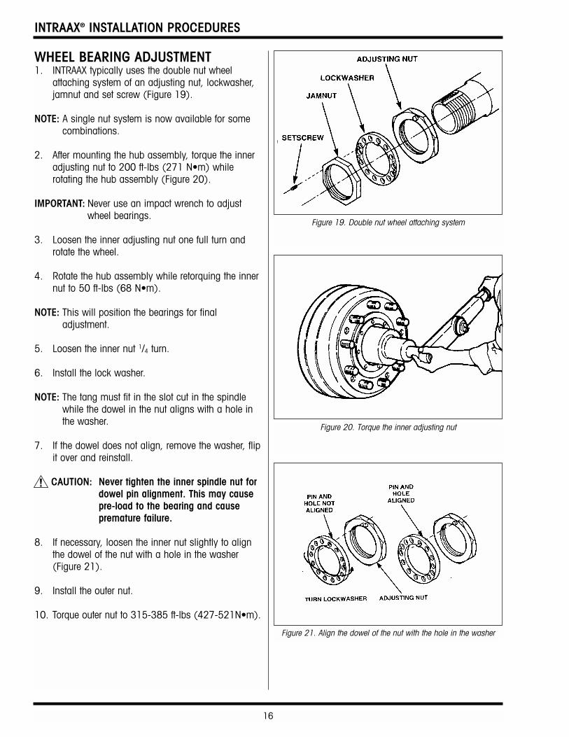
WHEEL BEARING ADJUSTMENT1. INTRAAX typically uses the double nut wheel
attaching system of an adjusting nut, lockwasher,jamnut and set screw (Figure 19).
NOTE: A single nut system is now available for somecombinations.
2. After mounting the hub assembly, torque the inneradjusting nut to 200 ft-lbs (271 N•m) whilerotating the hub assembly (Figure 20).
IMPORTANT: Never use an impact wrench to adjustwheel bearings.
3. Loosen the inner adjusting nut one full turn androtate the wheel.
4. Rotate the hub assembly while retorquing the innernut to 50 ft-lbs (68 N•m).
NOTE: This will position the bearings for finaladjustment.
5. Loosen the inner nut 1/4 turn.
6. Install the lock washer.
NOTE: The tang must fit in the slot cut in the spindlewhile the dowel in the nut aligns with a hole inthe washer.
7. If the dowel does not align, remove the washer, flipit over and reinstall.
CAUTION: Never tighten the inner spindle nut fordowel pin alignment. This may causepre-load to the bearing and causepremature failure.
8. If necessary, loosen the inner nut slightly to alignthe dowel of the nut with a hole in the washer(Figure 21).
9. Install the outer nut.
10. Torque outer nut to 315-385 ft-lbs (427-521N•m).
Figure 19. Double nut wheel attaching system
Figure 20. Torque the inner adjusting nut
Figure 21. Align the dowel of the nut with the hole in the washer
17
INTRAAX® INSTALLATION PROCEDURES
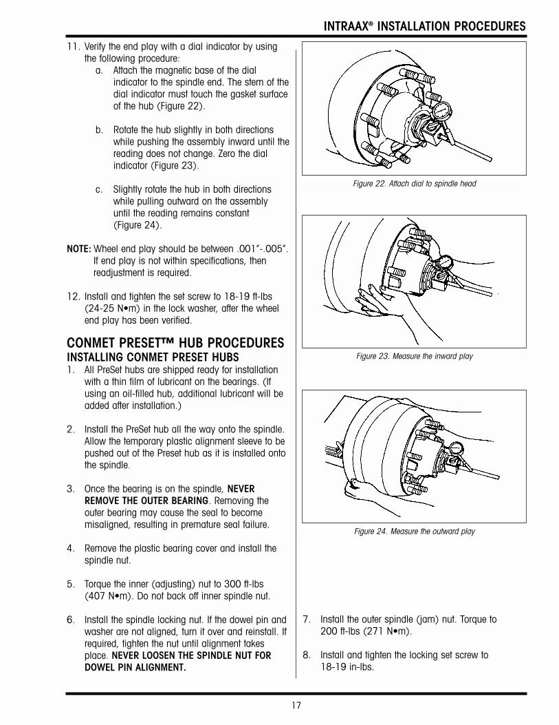
11. Verify the end play with a dial indicator by usingthe following procedure:
a. Attach the magnetic base of the dialindicator to the spindle end. The stem of thedial indicator must touch the gasket surfaceof the hub (Figure 22).
b. Rotate the hub slightly in both directionswhile pushing the assembly inward until thereading does not change. Zero the dialindicator (Figure 23).
c. Slightly rotate the hub in both directionswhile pulling outward on the assembly until the reading remains constant (Figure 24).
NOTE: Wheel end play should be between .001”-.005”.If end play is not within specifications, thenreadjustment is required.
12. Install and tighten the set screw to 18-19 ft-lbs(24-25 N•m) in the lock washer, after the wheelend play has been verified.
CONMET PRESET™ HUB PROCEDURESINSTALLING CONMET PRESET HUBS1. All PreSet hubs are shipped ready for installation
with a thin film of lubricant on the bearings. (Ifusing an oil-filled hub, additional lubricant will beadded after installation.)
2. Install the PreSet hub all the way onto the spindle.Allow the temporary plastic alignment sleeve to bepushed out of the Preset hub as it is installed ontothe spindle.
3. Once the bearing is on the spindle, NEVERREMOVE THE OUTER BEARING. Removing theouter bearing may cause the seal to becomemisaligned, resulting in premature seal failure.
4. Remove the plastic bearing cover and install thespindle nut.
5. Torque the inner (adjusting) nut to 300 ft-lbs (407 N•m). Do not back off inner spindle nut.
6. Install the spindle locking nut. If the dowel pin andwasher are not aligned, turn it over and reinstall. Ifrequired, tighten the nut until alignment takesplace. NEVER LOOSEN THE SPINDLE NUT FORDOWEL PIN ALIGNMENT.
Figure 22. Attach dial to spindle head
Figure 23. Measure the inward play
Figure 24. Measure the outward play
7. Install the outer spindle (jam) nut. Torque to 200 ft-lbs (271 N•m).
8. Install and tighten the locking set screw to 18-19 in-lbs.
INTRAAX® INSTALLATION PROCEDURES
18
ALIGNMENT PROCEDURE1. Tighten the torque-prevailing heavy hex nut on each
shear-type pivot bolt to hold the flanged eccentriccollar in place between the alignment guide, butloose enough to permit the hardened flat washersto rotate freely.
CAUTION: DO NOT APPLY OR ALLOW any type oflubricant to contact the threads of theshear-type pivot bolts. Lubricant willreduce the friction between thethreads of the bolts and the torque-prevailing heavy hex nut. Failure of theshear-type pivot bolts may occur.
CAUTION: DO NOT APPLY undercoating to thesuspension and frame bracket untilafter completing the alignment.Undercoating will effect clamp load ofthe pivot connection fastener and candamage the hardware.
IMPORTANT: You can reuse the shear-type pivot boltand torque-prevailing heavy hex nut onetime prior to the trailer being put intoservice. If future realignment becomesnecessary, you must use new pivot-connection hardware P/N S-24679 toprevent failure of the pivot connection dueto insufficient clamp load. Hendricksonprovides the means to achieve correct axlealignment. However, the OEM or repairfacility is responsible for proper assemblyand performing the axle alignment.Therefore, Hendrickson assumes noliability for pivot-joint failures or incorrectaxle alignment.
2. Inspect the orientation of the square hole in theflanged eccentric collar (outboard side). Thesquare hole should be at the twelve o’clock(12:00) position or the middle of the alignmentadjustment.
3. If necessary, adjust the flanged eccentric collar sothe square hole is at the 12:00 position. To adjustthe flanged eccentric collar, insert the 1/2" squaredrive breaker bar into the square hole in the flangedeccentric collar. Rotate the flanged eccentric collara maximum of 45 degrees clockwise orcounterclockwise to produce fore-and-aft axlepositioning.
AXLE ALIGNMENT — QUIK-ALIGNOVERVIEWThe QUIK-ALIGN alignment feature incorporates twoflanged washers that are inserted into slots located oneach side of the frame bracket. The outboard flangedwasher is eccentric. Its outside diameter is guided byan adjustment guide. Rotating the eccentric washerclockwise or counterclockwise provides fore and aftmovement at the suspension’s axle. The pivot connec-tion is clamped together with a torque prevailing heavyhex nut, hardened flat washers and shear-type bolt. Theshear-type bolt ensures proper torque and eliminatesthe need for a torque wrench.
REQUIRED MATERIALSThe following sockets and wrenches are needed toadjust QUIK-ALIGN equipped suspensions:
1. 1" drive E-20 Torx socket (Hendrickson P/N A-24536)
2. 17/16" wrench
3. 1/2" breaker bar
4. Impact wrench capable of 600 ft-lbs
ALIGNMENT PREPARATION1. The axle alignment site area should be flat, level
and free of debris.
NOTE: Alignment of sliders — If the suspension ismounted on a slider assembly, remove the slackin the locking pins to match the slider as closelyas possible to its operational state. Arecommended procedure is to lightly apply thetrailer’s brakes and gently pull forward, thusremoving all of the slack. This procedure willavoid pre-loading the TRI-FUNCTIONALBUSHINGS when moving the trailer.
2. Set the trailer’s bolster plate (upper coupler) to itsdesigned height by adjusting the landing gear. Setsuspension(s) at the ride height specified on thesuspension assembly drawing.
3. Inspect each tire set. Tires of each dual wheel set mustbe matched to a maximum of 1/8" tire radius or amaximum of 3/4" variation in tire circumference.
4. Secure trailer and release the trailer’s brakes. Thiswill allow wheel rotation while positioning thesuspension fore and aft.
19
INTRAAX® INSTALLATION PROCEDURES
4. Repeat steps 1 through 3 on the remaining pivotconnections.
5. Measuring from the trailer’s kingpin, rotate theflanged eccentric collar on one side of the forwardaxle clockwise or counterclockwise until both axleends are equal distance from the kingpin.
IMPORTANT: A maximum of 1/8" tolerance from side toside is considered acceptable.
6. If the flanged eccentric collar reaches 45 degreeswithout achieving alignment, rotate the flangedeccentric collar of the suspension’s other framebracket; repeat step 2.
IMPORTANT: Beyond 45 degrees in either the fore or theaft directions of the flanged eccentriccollar, there is no change in adjustment.
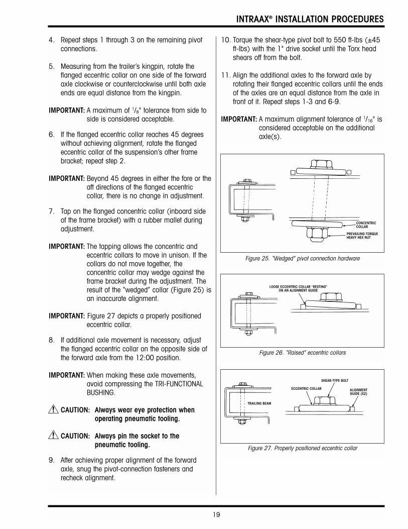
7. Tap on the flanged concentric collar (inboard sideof the frame bracket) with a rubber mallet duringadjustment.
IMPORTANT: The tapping allows the concentric andeccentric collars to move in unison. If thecollars do not move together, theconcentric collar may wedge against theframe bracket during the adjustment. Theresult of the “wedged” collar (Figure 25) isan inaccurate alignment.
IMPORTANT: Figure 27 depicts a properly positionedeccentric collar.
8. If additional axle movement is necessary, adjustthe flanged eccentric collar on the opposite side ofthe forward axle from the 12:00 position.
IMPORTANT: When making these axle movements,avoid compressing the TRI-FUNCTIONALBUSHING.
CAUTION: Always wear eye protection whenoperating pneumatic tooling.
CAUTION: Always pin the socket to thepneumatic tooling.
9. After achieving proper alignment of the forwardaxle, snug the pivot-connection fasteners andrecheck alignment.
10. Torque the shear-type pivot bolt to 550 ft-lbs (±45ft-lbs) with the 1" drive socket until the Torx headshears off from the bolt.
11. Align the additional axles to the forward axle byrotating their flanged eccentric collars until the endsof the axles are an equal distance from the axle infront of it. Repeat steps 1-3 and 6-9.
IMPORTANT: A maximum alignment tolerance of 1/16" isconsidered acceptable on the additionalaxle(s).
Figure 27. Properly positioned eccentric collar
Figure 25. “Wedged” pivot connection hardware
Figure 26. “Raised” eccentric collars
INTRAAX® INSTALLATION PROCEDURES
20
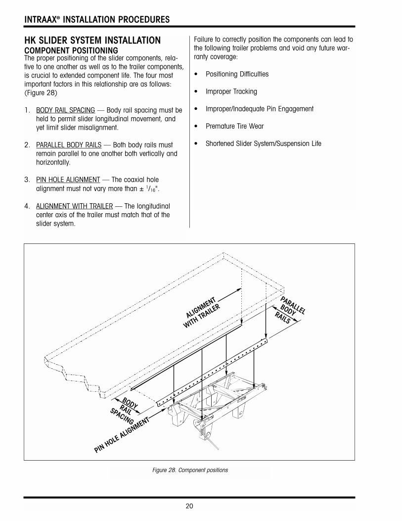
HK SLIDER SYSTEM INSTALLATIONCOMPONENT POSITIONINGThe proper positioning of the slider components, rela-tive to one another as well as to the trailer components,is crucial to extended component life. The four mostimportant factors in this relationship are as follows:(Figure 28)
1. BODY RAIL SPACING — Body rail spacing must beheld to permit slider longitudinal movement, andyet limit slider misalignment.
2. PARALLEL BODY RAILS — Both body rails mustremain parallel to one another both vertically andhorizontally.
3. PIN HOLE ALIGNMENT — The coaxial holealignment must not vary more than ± 1/16".
4. ALIGNMENT WITH TRAILER — The longitudinalcenter axis of the trailer must match that of theslider system.
Failure to correctly position the components can lead tothe following trailer problems and void any future war-ranty coverage:
• Positioning Difficulties
• Improper Tracking
• Improper/Inadequate Pin Engagement
• Premature Tire Wear
• Shortened Slider System/Suspension Life
Figure 28. Component positions
21
INTRAAX® INSTALLATION PROCEDURES
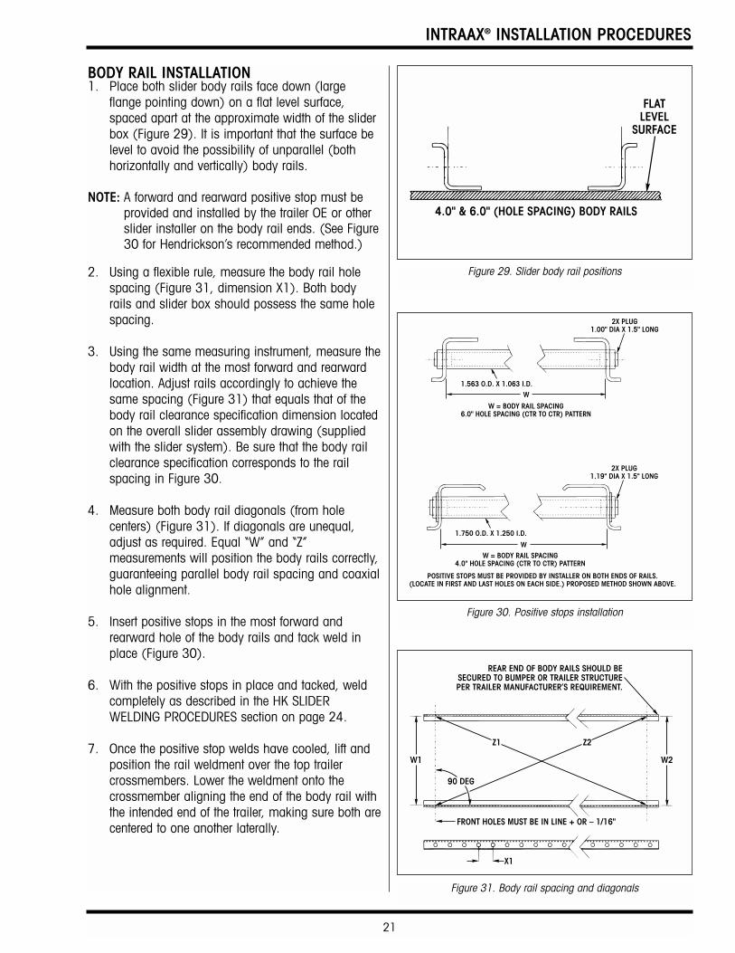
BODY RAIL INSTALLATION1. Place both slider body rails face down (large
flange pointing down) on a flat level surface,spaced apart at the approximate width of the sliderbox (Figure 29). It is important that the surface belevel to avoid the possibility of unparallel (bothhorizontally and vertically) body rails.
NOTE: A forward and rearward positive stop must beprovided and installed by the trailer OE or otherslider installer on the body rail ends. (See Figure30 for Hendrickson’s recommended method.)
2. Using a flexible rule, measure the body rail holespacing (Figure 31, dimension X1). Both bodyrails and slider box should possess the same holespacing.
3. Using the same measuring instrument, measure thebody rail width at the most forward and rearwardlocation. Adjust rails accordingly to achieve thesame spacing (Figure 31) that equals that of thebody rail clearance specification dimension locatedon the overall slider assembly drawing (suppliedwith the slider system). Be sure that the body railclearance specification corresponds to the railspacing in Figure 30.
4. Measure both body rail diagonals (from holecenters) (Figure 31). If diagonals are unequal,adjust as required. Equal “W” and “Z”measurements will position the body rails correctly,guaranteeing parallel body rail spacing and coaxialhole alignment.
5. Insert positive stops in the most forward andrearward hole of the body rails and tack weld inplace (Figure 30).
6. With the positive stops in place and tacked, weldcompletely as described in the HK SLIDERWELDING PROCEDURES section on page 24.
7. Once the positive stop welds have cooled, lift andposition the rail weldment over the top trailercrossmembers. Lower the weldment onto thecrossmember aligning the end of the body rail withthe intended end of the trailer, making sure both arecentered to one another laterally.
POSITIVE STOPS MUST BE PROVIDED BY INSTALLER ON BOTH ENDS OF RAILS.(LOCATE IN FIRST AND LAST HOLES ON EACH SIDE.) PROPOSED METHOD SHOWN ABOVE.
W = BODY RAIL SPACING6.0" HOLE SPACING (CTR TO CTR) PATTERN
2X PLUG1.00" DIA X 1.5" LONG
1.563 O.D. X 1.063 I.D.W
W = BODY RAIL SPACING4.0" HOLE SPACING (CTR TO CTR) PATTERN
2X PLUG1.19" DIA X 1.5" LONG
1.750 O.D. X 1.250 I.D.
W
Figure 29. Slider body rail positions
Figure 30. Positive stops installation
Figure 31. Body rail spacing and diagonals
INTRAAX® INSTALLATION PROCEDURES
22
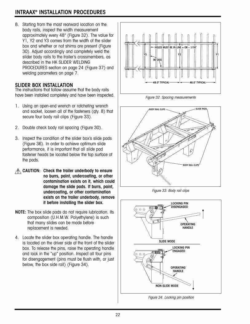
8. Starting from the most rearward location on thebody rails, inspect the width measurementapproximately every 48" (Figure 32). The value forY1, Y2 and Y3 comes from the width of the sliderbox and whether or not shims are present (Figure30). Adjust accordingly and completely weld theslider body rails to the trailer’s crossmembers, asdescribed in the HK SLIDER WELDINGPROCEDURES section on page 24 (Figure 37) andwelding parameters on page 7.
SLIDER BOX INSTALLATIONThe instructions that follow assume that the body railshave been installed completely and have been inspected.
1. Using an open-end wrench or ratcheting wrenchand socket, loosen all of the fasteners (qty. 8) thatsecure four body rail clips (Figure 33).
2. Double check body rail spacing (Figure 30).
3. Inspect the condition of the slider box’s slide pads(Figure 36). In order to achieve optimum slideperformance, it is important that all slide padfastener heads be located below the top surface ofthe pads.
CAUTION: Check the trailer underbody to ensureno burrs, paint, undercoating, or othercontamination exists on it, which coulddamage the slide pads. If burrs, paint,undercoating, or other contaminationexists on the trailer underbody, removeit before installing the slider box.
NOTE: The box slide pads do not require lubrication. Itscomposition (U.H.M.W. Polyethylene) is suchthat many slides can be made beforereplacement is needed.
4. Locate the slider box operating handle. The handleis located on the driver side at the front of the sliderbox. To release the pins, raise the operating handleand lock in the “up” position. Inspect all four pinsfor disengagement (pins must be flush with, or justbelow, the box side rail) (Figure 34).
Figure 32. Spacing measurements
Figure 33. Body rail clips
Figure 34. Locking pin position
OPERATINGHANDLE
LOCKING PINDISENGAGED
SLIDE MODE
OPERATINGHANDLE
LOCKING PINENGAGED
NON-SLIDE MODE
23
INTRAAX® INSTALLATION PROCEDURES
5. Lift and position the trailer over top of the sliderbox. Lower the trailer onto and between the sliderbody rails, making sure that the box end with theoperating handle is positioned closest to the trailerkingpin.
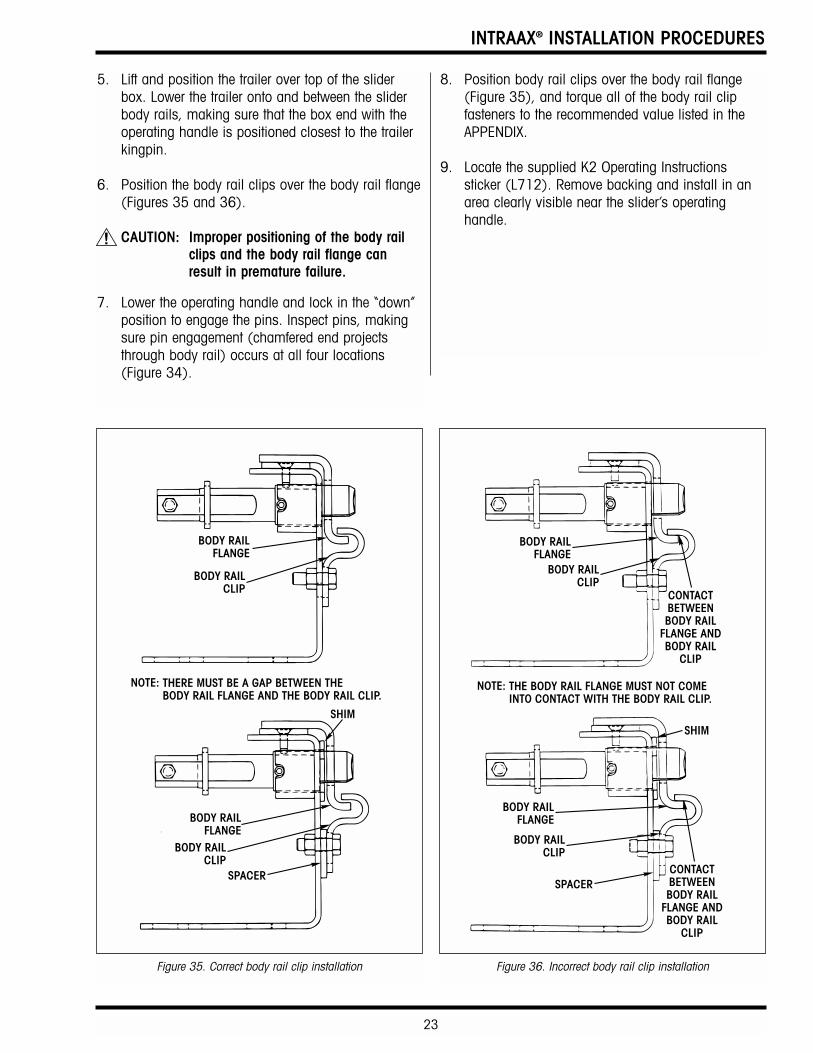
6. Position the body rail clips over the body rail flange(Figures 35 and 36).
CAUTION: Improper positioning of the body railclips and the body rail flange canresult in premature failure.
7. Lower the operating handle and lock in the “down”position to engage the pins. Inspect pins, makingsure pin engagement (chamfered end projectsthrough body rail) occurs at all four locations(Figure 34).
BODY RAILCLIP
BODY RAILCLIP
BODY RAILFLANGE
BODY RAILFLANGE
SHIM
SPACER
THERE MUST BE A GAP BETWEEN THEBODY RAIL FLANGE AND THE BODY RAIL CLIP.
NOTE:
BODY RAILCLIP
BODY RAILCLIP
CONTACTBETWEENBODY RAIL
FLANGE ANDBODY RAIL
CLIP
CONTACTBETWEENBODY RAIL
FLANGE ANDBODY RAIL
CLIP
BODY RAILFLANGE
BODY RAILFLANGE
SHIM
SPACER
THE BODY RAIL FLANGE MUST NOT COMEINTO CONTACT WITH THE BODY RAIL CLIP.
NOTE:
8. Position body rail clips over the body rail flange(Figure 35), and torque all of the body rail clipfasteners to the recommended value listed in theAPPENDIX.
9. Locate the supplied K2 Operating Instructionssticker (L712). Remove backing and install in anarea clearly visible near the slider’s operatinghandle.
Figure 35. Correct body rail clip installation Figure 36. Incorrect body rail clip installation
INTRAAX® INSTALLATION PROCEDURES
24
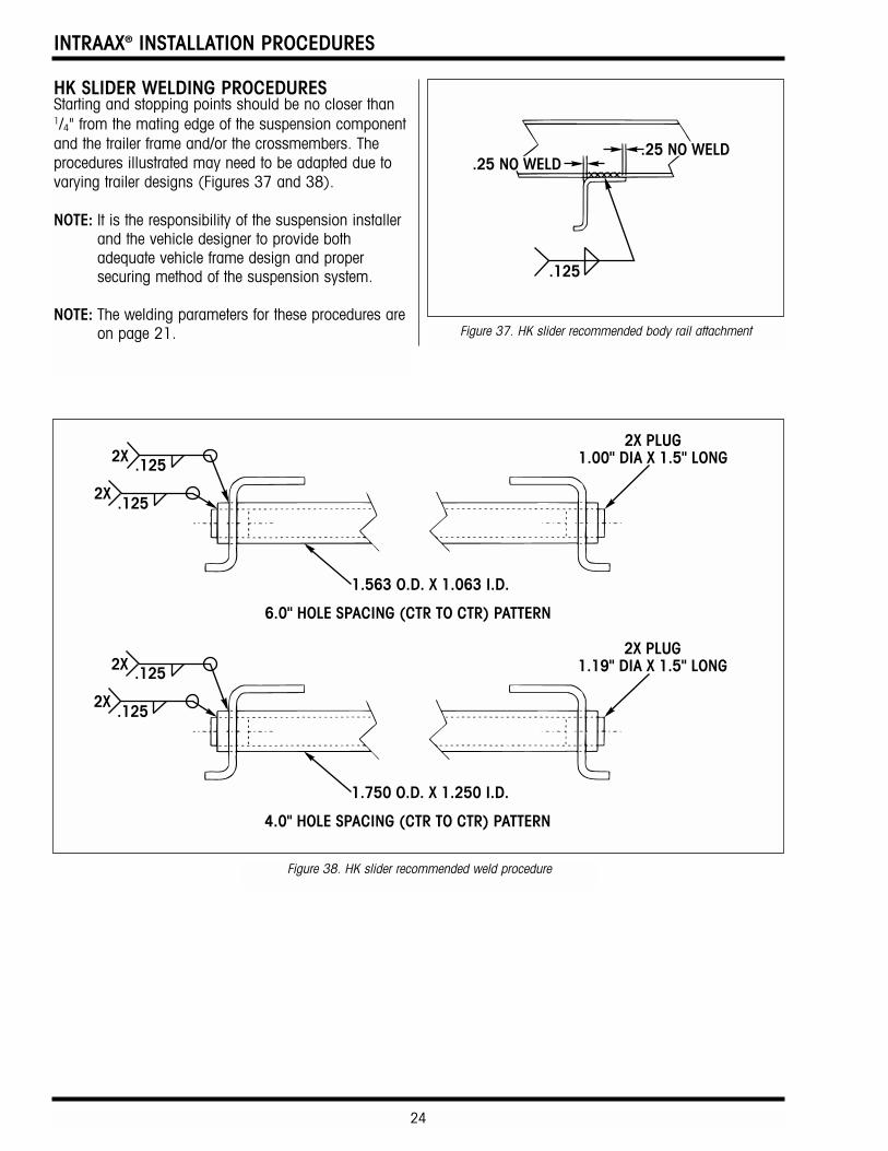
HK SLIDER WELDING PROCEDURESStarting and stopping points should be no closer than1/4" from the mating edge of the suspension componentand the trailer frame and/or the crossmembers. Theprocedures illustrated may need to be adapted due tovarying trailer designs (Figures 37 and 38).
NOTE: It is the responsibility of the suspension installerand the vehicle designer to provide bothadequate vehicle frame design and propersecuring method of the suspension system.
NOTE: The welding parameters for these procedures areon page 21. Figure 37. HK slider recommended body rail attachment
Figure 38. HK slider recommended weld procedure
25
INTRAAX® INSTALLATION PROCEDURES
FINAL INSPECTIONINSPECTION PROCEDURE1. Verify that the following welds have been completed
per specifications:
• Frame brackets to mounting frame (if applicable)
• Upper air spring/plate to mounting frame• Body rails to trailer crossmembers (slider
system)• Forward and rearward stop bars to slider
body rails (slider system)
2. Check that all suspension bolt torques are toHendrickson recommended specifications.
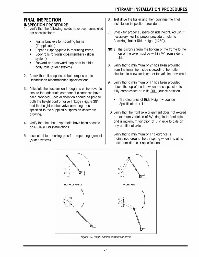
3. Articulate the suspension through its entire travel toensure that adequate component clearances havebeen provided. Special attention should be paid toboth the height control valve linkage (Figure 39)and the height control valve arm length asspecified in the supplied suspension assemblydrawing.
4. Verify that the shear-type bolts have been shearedon QUIK-ALIGN installations.
5. Inspect all four locking pins for proper engagement(slider system).
6. Test drive the trailer and then continue the finalinstallation inspection procedure.
7. Check for proper suspension ride height. Adjust, ifnecessary. For the proper procedure, refer toChecking Trailer Ride Height (L459).
NOTE: The distance from the bottom of the frame to thetop of the axle must be within 1/8" from side toside.
8. Verify that a minimum of 2" has been providedfrom the inner tire inside sidewall to the trailerstructure to allow for lateral or fore/aft tire movement.
9. Verify that a minimum of 1" has been providedabove the top of the tire when the suspension isfully compressed or in its FULL jounce position.
• Tire Clearance at Ride Height = Jounce Specification + 1"
10. Verify that the front axle alignment does not exceeda maximum variation of 1/8" kingpin to front axleand a maximum variation of 1/16" axle to axle onany additional axles.
11. Verify that a minimum of 1" clearance ismaintained around the air spring when it is at itsmaximum diameter specification.
Figure 39. Height control component travel
INTRAAX® INSTALLATION PROCEDURES
26
APPENDIX
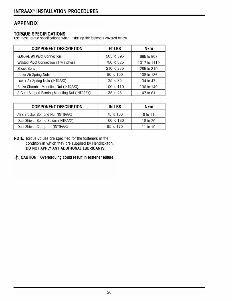
NOTE: Torque values are specified for the fasteners in thecondition in which they are supplied by Hendrickson.DO NOT APPLY ANY ADDITIONAL LUBRICANTS.
CAUTION: Overtorquing could result in fastener failure.
TORQUE SPECIFICATIONSUse these torque specifications when installing the fasteners covered below.
COMPONENT DESCRIPTION FT-LBS N•m
QUIK-ALIGN Pivot Connection
Welded Pivot Connection (11/8 inches)
Shock Bolts
Upper Air Spring Nuts
Lower Air Spring Nuts (INTRAAX)
Brake Chamber Mounting Nut (INTRAAX)
S-Cam Support Bearing Mounting Nut (INTRAAX)
505 to 595
750 to 825
210 to 235
80 to 100
25 to 35
100 to 110
35 to 45
685 to 807
1017 to 1119
285 to 319
108 to 136
34 to 47
136 to 149
47 to 61
COMPONENT DESCRIPTION IN-LBS N•m
ABS Bracket Bolt and Nut (INTRAAX)
Dust Shield, Bolt-to-Spider (INTRAAX)
Dust Shield, Clamp-on (INTRAAX)
75 to 100
160 to 180
95 to 170
8 to 11
18 to 20
11 to 19

www.hendrickson-intl.comL341 C 3-00 Printed in United States of America.
The Boler CompanyCopyright © 2000All Rights Reserved
Trailer Suspension Systems250 Chrysler Drive, Unit #3
Brampton, ON L6S 6B6 Canada905.789.1030
Fax 905.789.1033
Trailer Suspension Systems2070 Industrial Place SECanton, OH 44707-2600 USA330.456.7288Fax 330.456.0105