Embed Size (px)
Citation preview
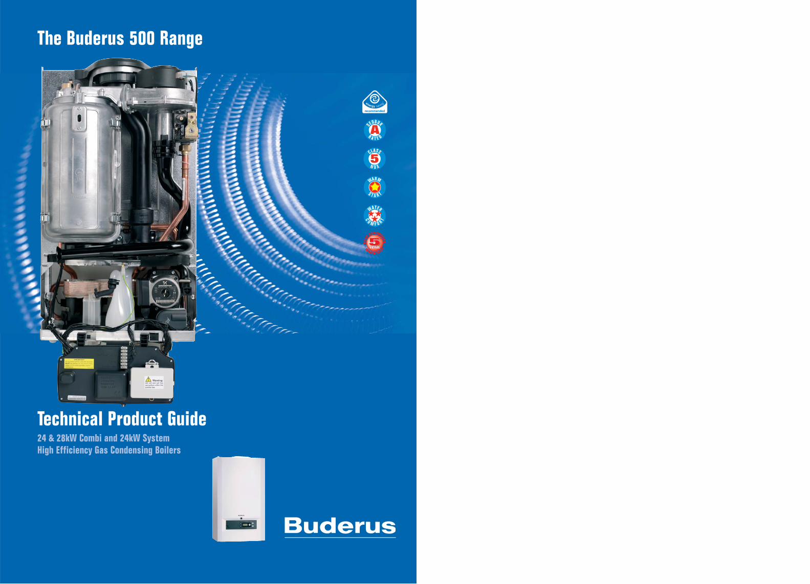
Technical Product Guide24 & 28kW Combi and 24kW SystemHigh Efficiency Gas Condensing Boilers
The Buderus 500 Range
WARM
S T A R T
5CLASS
N O X
AS
EDBUK
R A T E D
WATER
C
O M F O R T
2 33
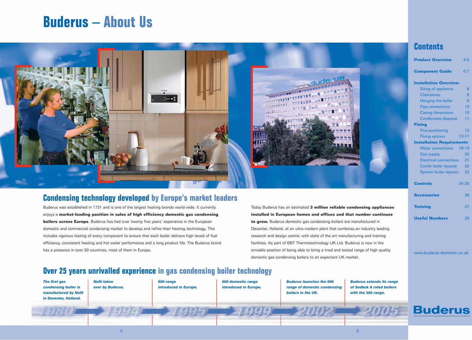
Buderus – About Us
Condensing technology developed by Europe’s market leadersBuderus was established in 1731 and is one of the largest heating brands world-wide. It currently
enjoys a market-leading position in sales of high efficiency domestic gas condensing
boilers across Europe. Buderus has had over twenty five years’ experience in the European
domestic and commercial condensing market to develop and refine their heating technology. This
includes rigorous testing of every component to ensure that each boiler delivers high levels of fuel
efficiency, consistent heating and hot water performance and a long product life. The Buderus brand
has a presence in over 50 countries, most of them in Europe.
Today Buderus has an estimated 3 million reliable condensing appliances
installed in European homes and offices and that number continues
to grow. Buderus domestic gas condensing boilers are manufactured in
Deventer, Holland, at an ultra-modern plant that combines an industry leading
research and design centre, with state of the art manufacturing and training
facilities. As part of BBT Thermotechnology UK Ltd, Buderus is now in the
enviable position of being able to bring a tried and tested range of high quality
domestic gas condensing boilers to an expectant UK market.
Over 25 years unrivalled experience in gas condensing boiler technologyThe first gas
condensing boiler is
manufactured by Nefit
in Deventer, Holland.
Nefit taken
over by Buderus.
800 range
introduced in Europe.
600 domestic range
introduced in Europe.
Buderus launches the 600
range of domestic condensing
boilers in the UK.
Buderus extends its range
of Sedbuk A rated boilers
with the 500 range.
ContentsProduct Overview 4-5
Component Guide 6-7
Installation OverviewSiting of appliance 8
Clearances 8
Hanging the boiler 9
Pipe connections 10
Casing dimensions 10
Condensate disposal 11
FluingFlue positioning 12
Fluing options 13-17
Installation RequirementsWater connections 18-19
Gas supply 20
Electrical connections 21
Combi boiler layouts 22
System boiler layouts 23
Controls 24-25
Accessories 26
Training 27
Useful Numbers 28
www.buderus-domestic.co.uk
54
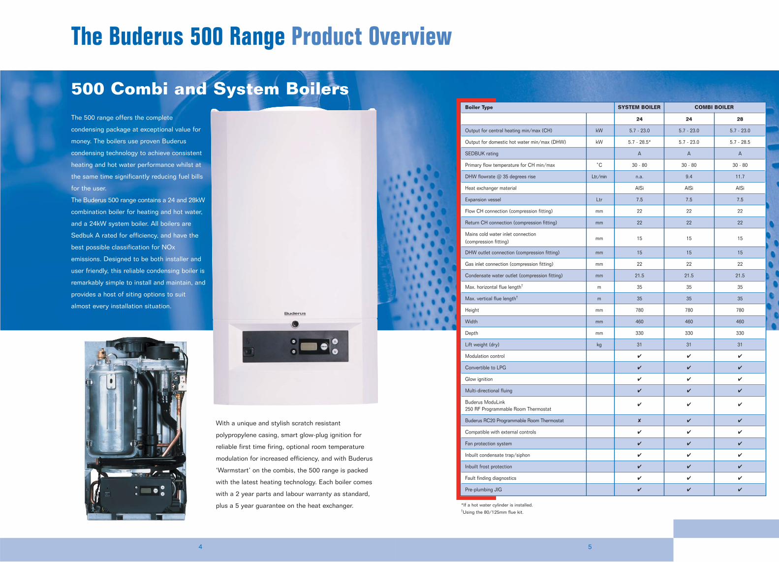
The Buderus 500 Range Product Overview
500 Combi and System Boilers
With a unique and stylish scratch resistant
polypropylene casing, smart glow-plug ignition for
reliable first time firing, optional room temperature
modulation for increased efficiency, and with Buderus
‘Warmstart’ on the combis, the 500 range is packed
with the latest heating technology. Each boiler comes
with a 2 year parts and labour warranty as standard,
plus a 5 year guarantee on the heat exchanger.
Boiler Type SYSTEM BOILER COMBI BOILER
24 24 28
Output for central heating min/max (CH) kW 5.7 - 23.0 5.7 - 23.0 5.7 - 23.0
Output for domestic hot water min/max (DHW) kW 5.7 - 28.5* 5.7 - 23.0 5.7 - 28.5
SEDBUK rating A A A
Primary flow temperature for CH min/max ˚C 30 - 80 30 - 80 30 - 80
DHW flowrate @ 35 degrees rise Ltr./min n.a. 9.4 11.7
Heat exchanger material AlSi AlSi AlSi
Expansion vessel Ltr 7.5 7.5 7.5
Flow CH connection (compression fitting) mm 22 22 22
Return CH connection (compression fitting) mm 22 22 22
Mains cold water inlet connection (compression fitting)
mm 15 15 15
DHW outlet connection (compression fitting) mm 15 15 15
Gas inlet connection (compression fitting) mm 22 22 22
Condensate water outlet (compression fitting) mm 21.5 21.5 21.5
Max. horizontal flue length† m 35 35 35
Max. vertical flue length† m 35 35 35
Height mm 780 780 780
Width mm 460 460 460
Depth mm 330 330 330
Lift weight (dry) kg 31 31 31
Modulation control � � �
Convertible to LPG � � �
Glow ignition � � �
Multi-directional fluing � � �
Buderus ModuLink250 RF Programmable Room Thermostat
� � �
Buderus RC20 Programmable Room Thermostat � � �
Compatible with external controls � � �
Fan protection system � � �
Inbuilt condensate trap/siphon � � �
Inbuilt frost protection � � �
Fault finding diagnostics � � �
Pre-plumbing JIG � � �
The 500 range offers the complete
condensing package at exceptional value for
money. The boilers use proven Buderus
condensing technology to achieve consistent
heating and hot water performance whilst at
the same time significantly reducing fuel bills
for the user.
The Buderus 500 range contains a 24 and 28kW
combination boiler for heating and hot water,
and a 24kW system boiler. All boilers are
Sedbuk A rated for efficiency, and have the
best possible classification for NOx
emissions. Designed to be both installer and
user friendly, this reliable condensing boiler is
remarkably simple to install and maintain, and
provides a host of siting options to suit
almost every installation situation.
*If a hot water cylinder is installed.†Using the 80/125mm flue kit.
7
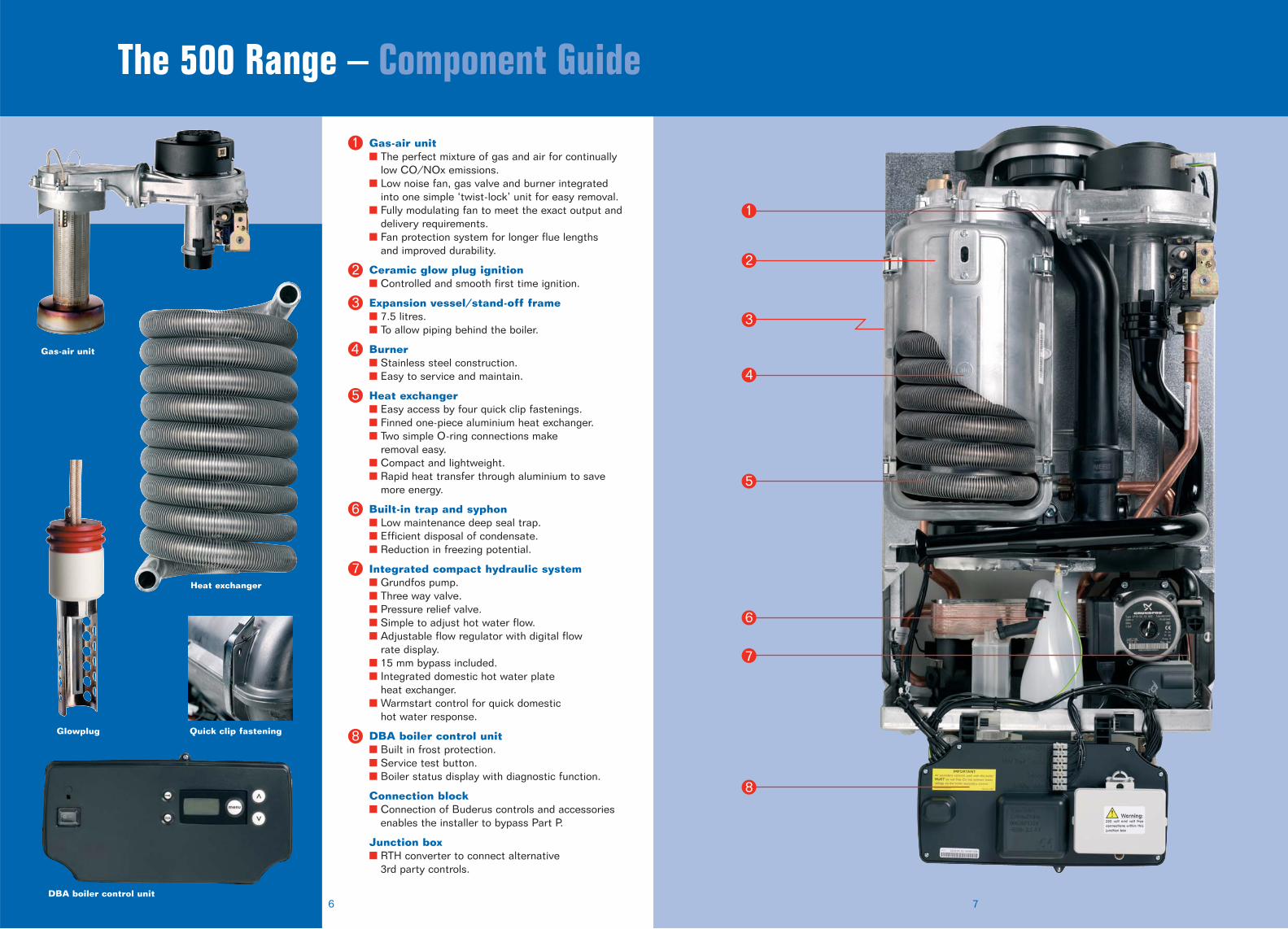
The 500 Range – Component Guide
6
Gas-air unit
Heat exchanger
Gas-air unit� The perfect mixture of gas and air for continually
low CO/NOx emissions.� Low noise fan, gas valve and burner integrated
into one simple ‘twist-lock’ unit for easy removal.� Fully modulating fan to meet the exact output and
delivery requirements.� Fan protection system for longer flue lengths
and improved durability.
Ceramic glow plug ignition� Controlled and smooth first time ignition.
Expansion vessel/stand-off frame� 7.5 litres.� To allow piping behind the boiler.
Burner� Stainless steel construction.� Easy to service and maintain.
Heat exchanger� Easy access by four quick clip fastenings.� Finned one-piece aluminium heat exchanger.� Two simple O-ring connections make
removal easy.� Compact and lightweight.� Rapid heat transfer through aluminium to save
more energy.
Built-in trap and syphon� Low maintenance deep seal trap.� Efficient disposal of condensate.� Reduction in freezing potential.
Integrated compact hydraulic system� Grundfos pump.� Three way valve.� Pressure relief valve.� Simple to adjust hot water flow.� Adjustable flow regulator with digital flow
rate display.� 15 mm bypass included.� Integrated domestic hot water plate
heat exchanger.� Warmstart control for quick domestic
hot water response.
DBA boiler control unit� Built in frost protection.� Service test button.� Boiler status display with diagnostic function.
Connection block � Connection of Buderus controls and accessories
enables the installer to bypass Part P.
Junction box � RTH converter to connect alternative
3rd party controls.
Quick clip fastening
DBA boiler control unit
Glowplug
1
2
3
4
5
6
7
8
1
2
3
4
5
6
7
8
98
The 500 Range – Installation Overview
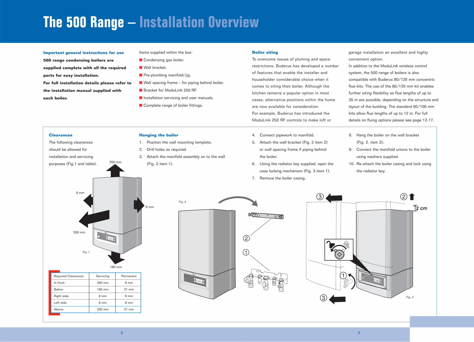
Clearances
The following clearances
should be allowed for
installation and servicing
purposes (Fig.1 and table).
8 mm
8 mm
180 mm
200 mm
350 mm
Hanging the boiler
1. Position the wall mounting template.
2. Drill holes as required.
3. Attach the manifold assembly on to the wall
(Fig. 2 item 1).
1
Fig. 2
Fig. 3
Fig. 1
Required Clearances Servicing Permanent
In front: 350 mm 8 mm
Below: 180 mm 21 mm
Right side: 8 mm 8 mm
Left side: 8 mm 8 mm
Above: 200 mm 21 mm
Important general instructions for use
500 range condensing boilers are
supplied complete with all the required
parts for easy installation.
For full installation details please refer to
the installation manual supplied with
each boiler.
Items supplied within the box:
� Condensing gas boiler.
� Wall bracket.
� Pre-plumbing manifold/jig.
� Wall spacing frame – for piping behind boiler.
� Bracket for ModuLink 250 RF.
� Installation servicing and user manuals.
� Complete range of boiler fittings.
Boiler siting
To overcome issues of pluming and space
restrictions, Buderus has developed a number
of features that enable the installer and
householder considerable choice when it
comes to siting their boiler. Although the
kitchen remains a popular option in most
cases, alternative positions within the home
are now available for consideration.
For example, Buderus has introduced the
ModuLink 250 RF controls to make loft or
garage installation an excellent and highly
convenient option.
In addition to the ModuLink wireless control
system, the 500 range of boilers is also
compatible with Buderus 80/125 mm concentric
flue kits. The use of the 80/125 mm kit enables
further siting flexibility as flue lengths of up to
35 m are possible, depending on the structure and
layout of the building. The standard 60/100 mm
kits allow flue lengths of up to 12 m. For full
details on fluing options please see page 12-17.
4. Connect pipework to manifold.
5. Attach the wall bracket (Fig. 2 item 2)
or wall spacing frame if piping behind
the boiler.
6. Using the radiator key supplied, open the
case locking mechanism (Fig. 3 item 1).
7. Remove the boiler casing.
8. Hang the boiler on the wall bracket
(Fig. 2. item 2).
9. Connect the manifold unions to the boiler
using washers supplied.
10. Re-attach the boiler casing and lock using
the radiator key.
1110
Quick Installation Overview continued
460 mm
330 mm
150 mm
35 mm
780
mm
(6) 108 mm
Ø100 mm
Ø60 mm
328 mm
376 mm
721
mm
200 mm
(7) 93 mm
(1-2-5) 85 mm
(3-4) 70 mm1 3 5 4 2 7
outside edge frame
222 mm
352 mm
403.8 mm
92 mm
6
230 mm
152 mm
282 mm / 287 mm
157 mm / 162 mm
8 mm 8 mm 21 m
m21
mm
8 mm
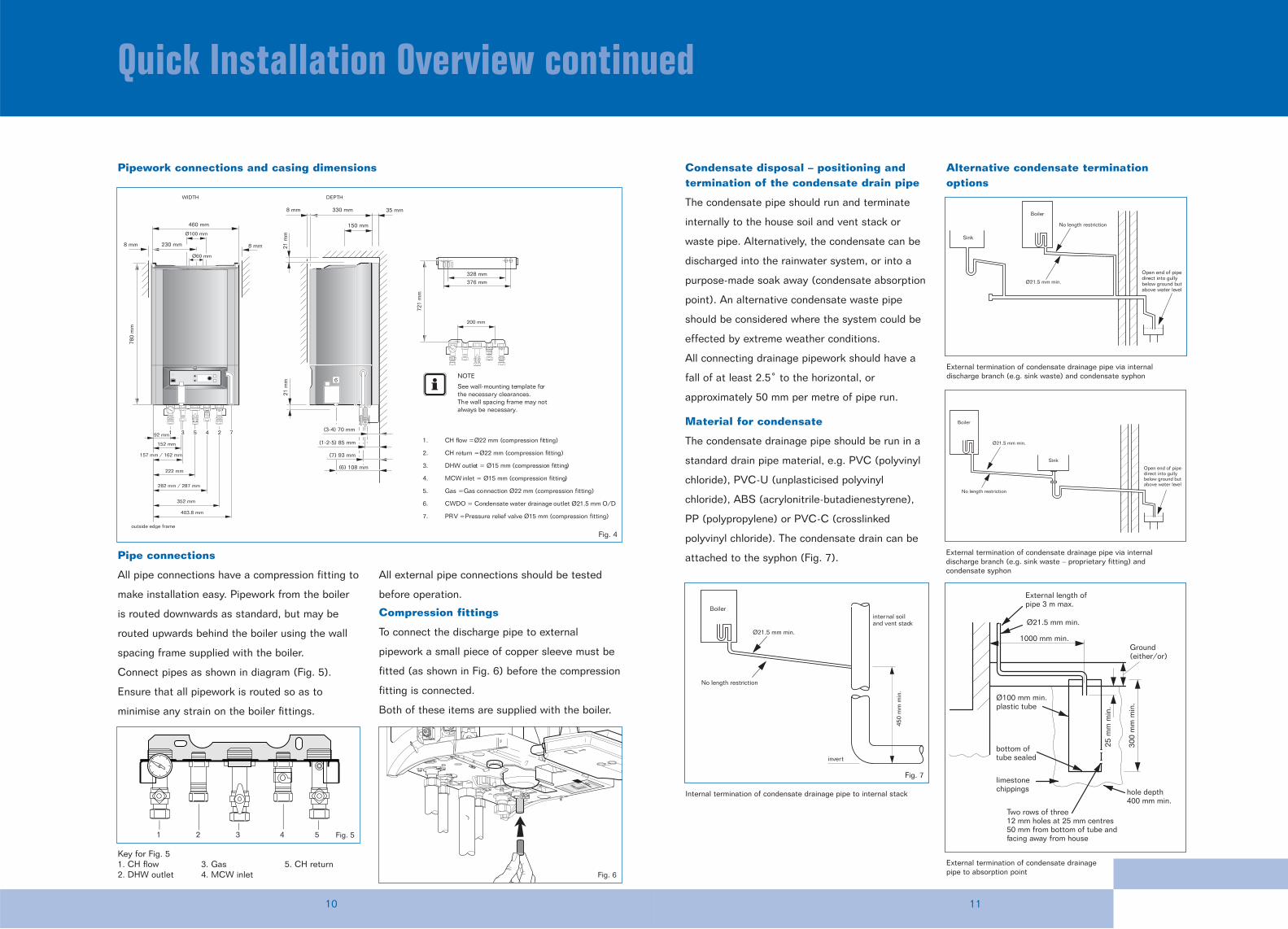
1. CH flow = Ø22 mm (compression fitting)
2. CH return = Ø22 mm (compression fitting)
3. DHW outlet = Ø15 mm (compression fitting)
4. MCW inlet = Ø15 mm (compression fitting)
5. Gas = Gas connection Ø22 mm (compression fitting)
6. CWDO = Condensate water drainage outlet Ø21.5 mm O/D
7. PRV = Pressure relief valve Ø15 mm (compression fitting)
NOTE
See wall-mounting template for the necessary clearances. The wall spacing frame may not always be necessary.
WIDTH DEPTH
Pipework connections and casing dimensions
1 2 3 4 5
Key for Fig. 51. CH flow2. DHW outlet
3. Gas4. MCW inlet
5. CH return
Condensate disposal – positioning andtermination of the condensate drain pipe
The condensate pipe should run and terminate
internally to the house soil and vent stack or
waste pipe. Alternatively, the condensate can be
discharged into the rainwater system, or into a
purpose-made soak away (condensate absorption
point). An alternative condensate waste pipe
should be considered where the system could be
effected by extreme weather conditions.
All connecting drainage pipework should have a
fall of at least 2.5˚ to the horizontal, or
approximately 50 mm per metre of pipe run.
Material for condensate
The condensate drainage pipe should be run in a
standard drain pipe material, e.g. PVC (polyvinyl
chloride), PVC-U (unplasticised polyvinyl
chloride), ABS (acrylonitrile-butadienestyrene),
PP (polypropylene) or PVC-C (crosslinked
polyvinyl chloride). The condensate drain can be
attached to the syphon (Fig. 7).
Alternative condensate terminationoptions
Pipe connections
All pipe connections have a compression fitting to
make installation easy. Pipework from the boiler
is routed downwards as standard, but may be
routed upwards behind the boiler using the wall
spacing frame supplied with the boiler.
Connect pipes as shown in diagram (Fig. 5).
Ensure that all pipework is routed so as to
minimise any strain on the boiler fittings.
All external pipe connections should be tested
before operation.
Compression fittings
To connect the discharge pipe to external
pipework a small piece of copper sleeve must be
fitted (as shown in Fig. 6) before the compression
fitting is connected.
Both of these items are supplied with the boiler.
No length restriction
Boiler
Open end of pipedirect into gullybelow ground butabove water level
Ø21.5 mm min.
Sink
Ø100 mm min.plastic tube
bottom oftube sealed
limestonechippings hole depth
400 mm min.
300
mm
min
.
25 m
m m
in.
Ground(either/or)
Two rows of three12 mm holes at 25 mm centres50 mm from bottom of tube andfacing away from house
1000 mm min.
Ø21.5 mm min.
External length ofpipe 3 m max.
No length restriction
Ø21.5 mm min.
Open end of pipedirect into gullybelow ground butabove water level
Boiler
Sink
External termination of condensate drainage pipe via internaldischarge branch (e.g. sink waste) and condensate syphon
External termination of condensate drainagepipe to absorption point
External termination of condensate drainage pipe via internaldischarge branch (e.g. sink waste – proprietary fitting) andcondensate syphon
Fig. 5
Fig. 6
Fig. 4
No length restriction
Ø21.5 mm min.
internal soiland vent stack
invert
Boiler
450
mm
min
.
Internal termination of condensate drainage pipe to internal stack
Fig. 7
1312
The 500 Range – Fluing Options
Buderus gas condensing boilers allow for a
variety of fluing options to suit almost any
domestic installation. This allows the installer
greater flexibility in siting the appliance and
makes loft or garage installations a workable
alternative to the traditional kitchen installation,
particularly when the boiler is used in conjunction
with the ModuLink 250 wireless programmable
room thermostat. This extra siting flexibility is
especially useful to avoid issues of pluming, which
sometimes occurs when the boiler is operating at
maximum efficiency. A complete list of all flue
accessories and part numbers can be found on
page 26.
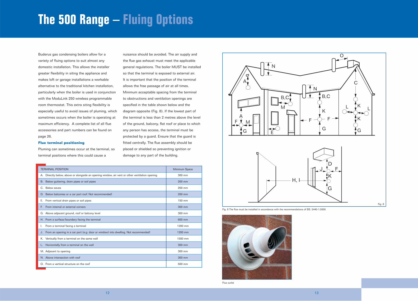
Flue terminal positioning
Pluming can sometimes occur at the terminal, so
terminal positions where this could cause a
nuisance should be avoided. The air supply and
the flue gas exhaust must meet the applicable
general regulations. The boiler MUST be installed
so that the terminal is exposed to external air.
It is important that the position of the terminal
allows the free passage of air at all times.
Minimum acceptable spacing from the terminal
to obstructions and ventilation openings are
specified in the table shown below and the
diagram opposite (Fig. 8). If the lowest part of
the terminal is less than 2 metres above the level
of the ground, balcony, flat roof or place to which
any person has access, the terminal must be
protected by a guard. Ensure that the guard is
fitted centrally. The flue assembly should be
placed or shielded so preventing ignition or
damage to any part of the building.
AF M
G
M
B,C
F F
B,C
K
G
K
K
G
C
L L
A
N
N
O
E
FJK
G
D
H, I
TERMINAL POSITION Minimum Space
A. Directly below, above or alongside an opening window, air vent or other ventilation opening 300 mm
B. Below guttering, drain pipes or soil pipes 200 mm
C. Below eaves 200 mm
D. Below balconies or a car port roof. Not recommended! 200 mm
E. From vertical drain pipes or soil pipes 150 mm
F. From internal or external corners 300 mm
G. Above adjacent ground, roof or balcony level 300 mm
H. From a surface/boundary facing the terminal 600 mm
I. From a terminal facing a terminal 1200 mm
J. From an opening in a car port (e.g. door or window) into dwelling. Not recommended! 1200 mm
K. Vertically from a terminal on the same wall 1500 mm
L. Horizontally from a terminal on the wall 300 mm
M. Adjacent to opening 300 mm
N. Above intersection with roof 300 mm
O. From a vertical structure on the roof 500 mm
Fig. 8 The flue must be installed in accordance with the recommendations of BS. 5440-1:2000
Flue outlet
Fig. 8
Flue accessories
1514
Fluing Options continued
Flue lengths
Two adaptors (T-000-083-723 + T-000-083-707) are
required for 80/125 mm systems – see accessories.
Flue diameter 60/100 mm 80/125 mm
Maximum flue length 12 m 35 m
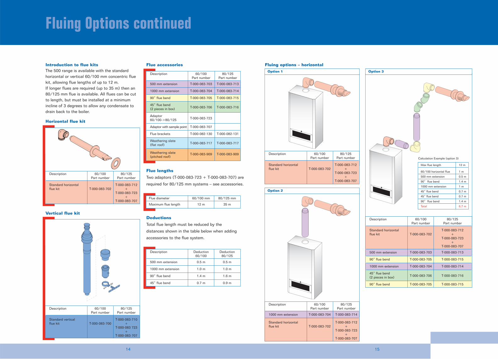
Option 1
Option 2
Horizontal flue kit
Fluing options – horizontal
Vertical flue kit
Description 60/100 80/125Part number Part number
500 mm extension T-000-083-703 T-000-083-713
1000 mm extension T-000-083-704 T-000-083-714
90˚ flue bend T-000-083-705 T-000-083-715
45˚ flue bend (2 pieces in box) T-000-083-706 T-000-083-716
Adaptor 60/100->80/125 T-000-083-723
Adaptor with sample point T-000-083-707
Flue brackets T-000-082-130 T-000-082-131
Weathering slate(flat roof) T-000-083-717 T-000-083-717
Weathering slate(pitched roof)
T-000-083-909 T-000-083-909
Description Deduction Deduction60/100 80/125
500 mm extension 0.5 m 0.5 m
1000 mm extension 1.0 m 1.0 m
90˚ flue bend 1.4 m 1.6 m
45˚ flue bend 0.7 m 0.9 m
Option 3
Introduction to flue kitsThe 500 range is available with the standardhorizontal or vertical 60/100 mm concentric fluekit, allowing flue lengths of up to 12 m. If longer flues are required (up to 35 m) then an80/125 mm flue is available. All flues can be cutto length, but must be installed at a minimumincline of 3 degrees to allow any condensate todrain back to the boiler.
Max flue length 12 m
60/100 horizontal flue 1 m
500 mm extension 0.5 m
90˚ flue bend 1.4 m
1000 mm extension 1 m
45˚ flue bend 0.7 m
45˚ flue bend 0.7 m
90˚ flue bend 1.4 m
Total 6.7 m
Calculation Example (option 3)
Description 60/100 80/125Part number Part number
Standard vertical T-000-083-710flue kit T-000-083-700 +
T-000-083 723+
T-000-083-707
Description 60/100 80/125Part number Part number
Standard horizontal T-000-083-712flue kit T-000-083-702 +
T-000-083-723+
T-000-083-707
Description 60/100 80/125Part number Part number
Standard horizontal T-000-083-712flue kit T-000-083-702 +
T-000-083-723+
T-000-083-707
Description 60/100 80/125Part number Part number
1000 mm extension T-000-083-704 T-000-083-714
Standard horizontal T-000-083-712flue kit T-000-083-702 +
T-000-083-723+
T-000-083-707
Description 60/100 80/125Part number Part number
Standard horizontal T-000-083-712flue kit T-000-083-702 +
T-000-083-723+
T-000-083-707
500 mm extension T-000-083-703 T-000-083-713
90˚ flue bend T-000-083-705 T-000-083-715
1000 mm extension T-000-083-704 T-000-083-714
45˚ flue bend (2 pieces in box) T-000-083-706 T-000-083-716
90˚ flue bend T-000-083-705 T-000-083-715
Deductions
Total flue length must be reduced by the
distances shown in the table below when adding
accessories to the flue system.
1716
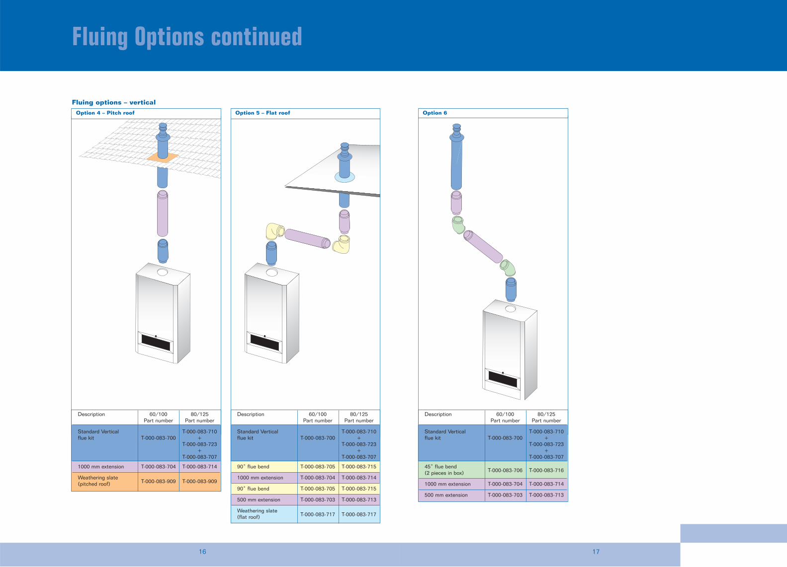
Fluing Options continued
Option 4 – Pitch roof
B
I
Option 5 – Flat roof Option 6
Fluing options – vertical
Description 60/100 80/125Part number Part number
Standard Vertical T-000-083-710flue kit T-000-083-700 +
T-000-083-723+
T-000-083-707
1000 mm extension T-000-083-704 T-000-083-714
Weathering slate(pitched roof) T-000-083-909 T-000-083-909
Description 60/100 80/125Part number Part number
Standard Vertical T-000-083-710flue kit T-000-083-700 +
T-000-083-723+
T-000-083-707
90˚ flue bend T-000-083-705 T-000-083-715
1000 mm extension T-000-083-704 T-000-083-714
90˚ flue bend T-000-083-705 T-000-083-715
500 mm extension T-000-083-703 T-000-083-713
Weathering slate(flat roof) T-000-083-717 T-000-083-717
Description 60/100 80/125Part number Part number
Standard Vertical T-000-083-710flue kit T-000-083-700 +
T-000-083-723+
T-000-083-707
45˚ flue bend (2 pieces in box) T-000-083-706 T-000-083-716
1000 mm extension T-000-083-704 T-000-083-714
500 mm extension T-000-083-703 T-000-083-713
1918
The 500 Range – Installation Requirements
Installation of the 500 range must be in
accordance with the relevant requirements of the
Gas Safety (Installation and Use) Regulations (as
amended), current IEE Wiring Regulations, local
Building Regulations, Building Standards
(Scotland) (Consolidation) regulations and bylaws
of the local Water company and Health and
Safety Document No. 635 (Electricity at Work
Regulations 1989). It should be in accordance
with the relevant recommendations of the
following British Standards:
BS 6798; BS 5449; BS 5546:1; BS 5440:1;
BS 5440:2; BS 6891.
All gas appliances must be installed by a CORGI
registered person in accordance with the above
regulations. Failure to install appliances correctly
could lead to prosecution.
The manufacturer’s notes must not be taken in
any way as overriding statutory regulations.
Mains cold water supply
A direct mains cold water connection is
permitted by local water authorities. However,
it is recommended that reference be made to
local requirements. In the event of difficulty
contact the Buderus Technical Department
on 0870 421 5944.
Pipe sizing
Unless the mains pressure is low, a standard
15 mm diameter service pipe is normally suitable.
A 15 mm hot water distribution pipe is
recommended. The manifold of the boiler has a
22mm compression fitting as standard for central
heating and 15mm compression fitting for
domestic hot water.
Cold water connection
Connection should be made in accordance with
the layout shown on page 10. Wherever possible
the cold supply to the appliance should be the
first connection off the mains supply in order to
minimise hot water flow reduction when cold
water services are operated. The final 600 mm of
piping to the appliance should be copper only.
Cold water pressure
To achieve the stipulated flow rate a working cold
water mains pressure of 1.3bar is required. The
appliance will operate at a minimum working
pressure of only 0.2bar (3 psi). However a
reduced hot water flow rate should be expected.
Where back-flow prevention devices, including
water meters are fitted, the expansion of hot
water into the cold water main will be prevented.
This can result in a pressure build-up that may
cause damage to the boiler and household
devices such as showers, washing machines, etc.
In these cases we recommend that a mini-
expansion vessel be fitted adjacent to the boiler
in the cold water main.
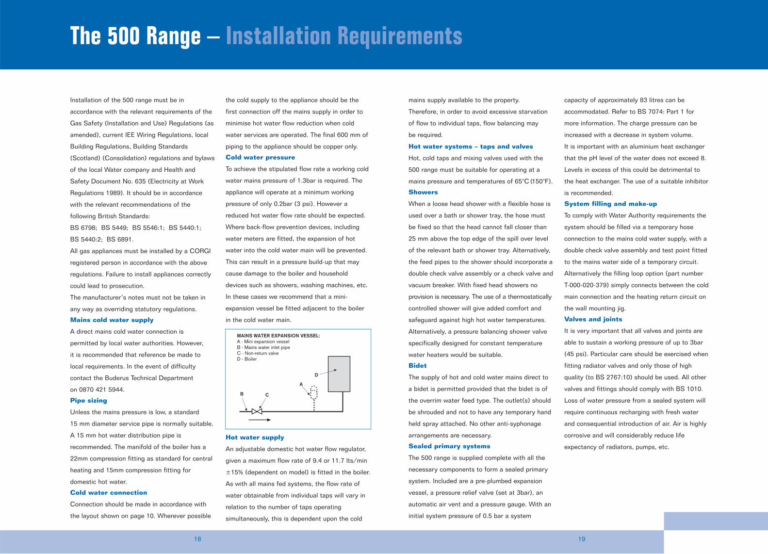
Hot water supply
An adjustable domestic hot water flow regulator,
given a maximum flow rate of 9.4 or 11.7 lts/min
±15% (dependent on model) is fitted in the boiler.
As with all mains fed systems, the flow rate of
water obtainable from individual taps will vary in
relation to the number of taps operating
simultaneously, this is dependent upon the cold
D
C
A
B
MAINS WATER EXPANSION VESSEL:A - Mini expansion vesselB - Mains water inlet pipeC - Non-return valveD - Boiler
mains supply available to the property.
Therefore, in order to avoid excessive starvation
of flow to individual taps, flow balancing may
be required.
Hot water systems – taps and valves
Hot, cold taps and mixing valves used with the
500 range must be suitable for operating at a
mains pressure and temperatures of 65°C (150°F).
Showers
When a loose head shower with a flexible hose is
used over a bath or shower tray, the hose must
be fixed so that the head cannot fall closer than
25 mm above the top edge of the spill over level
of the relevant bath or shower tray. Alternatively,
the feed pipes to the shower should incorporate a
double check valve assembly or a check valve and
vacuum breaker. With fixed head showers no
provision is necessary. The use of a thermostatically
controlled shower will give added comfort and
safeguard against high hot water temperatures.
Alternatively, a pressure balancing shower valve
specifically designed for constant temperature
water heaters would be suitable.
Bidet
The supply of hot and cold water mains direct to
a bidet is permitted provided that the bidet is of
the overrim water feed type. The outlet(s) should
be shrouded and not to have any temporary hand
held spray attached. No other anti-syphonage
arrangements are necessary.
Sealed primary systems
The 500 range is supplied complete with all the
necessary components to form a sealed primary
system. Included are a pre-plumbed expansion
vessel, a pressure relief valve (set at 3bar), an
automatic air vent and a pressure gauge. With an
initial system pressure of 0.5 bar a system
capacity of approximately 83 litres can be
accommodated. Refer to BS 7074: Part 1 for
more information. The charge pressure can be
increased with a decrease in system volume.
It is important with an aluminium heat exchanger
that the pH level of the water does not exceed 8.
Levels in excess of this could be detrimental to
the heat exchanger. The use of a suitable inhibitor
is recommended.
System filling and make-up
To comply with Water Authority requirements the
system should be filled via a temporary hose
connection to the mains cold water supply, with a
double check valve assembly and test point fitted
to the mains water side of a temporary circuit.
Alternatively the filling loop option (part number
T-000-020-379) simply connects between the cold
main connection and the heating return circuit on
the wall mounting jig.
Valves and joints
It is very important that all valves and joints are
able to sustain a working pressure of up to 3bar
(45 psi). Particular care should be exercised when
fitting radiator valves and only those of high
quality (to BS 2767:10) should be used. All other
valves and fittings should comply with BS 1010.
Loss of water pressure from a sealed system will
require continuous recharging with fresh water
and consequential introduction of air. Air is highly
corrosive and will considerably reduce life
expectancy of radiators, pumps, etc.
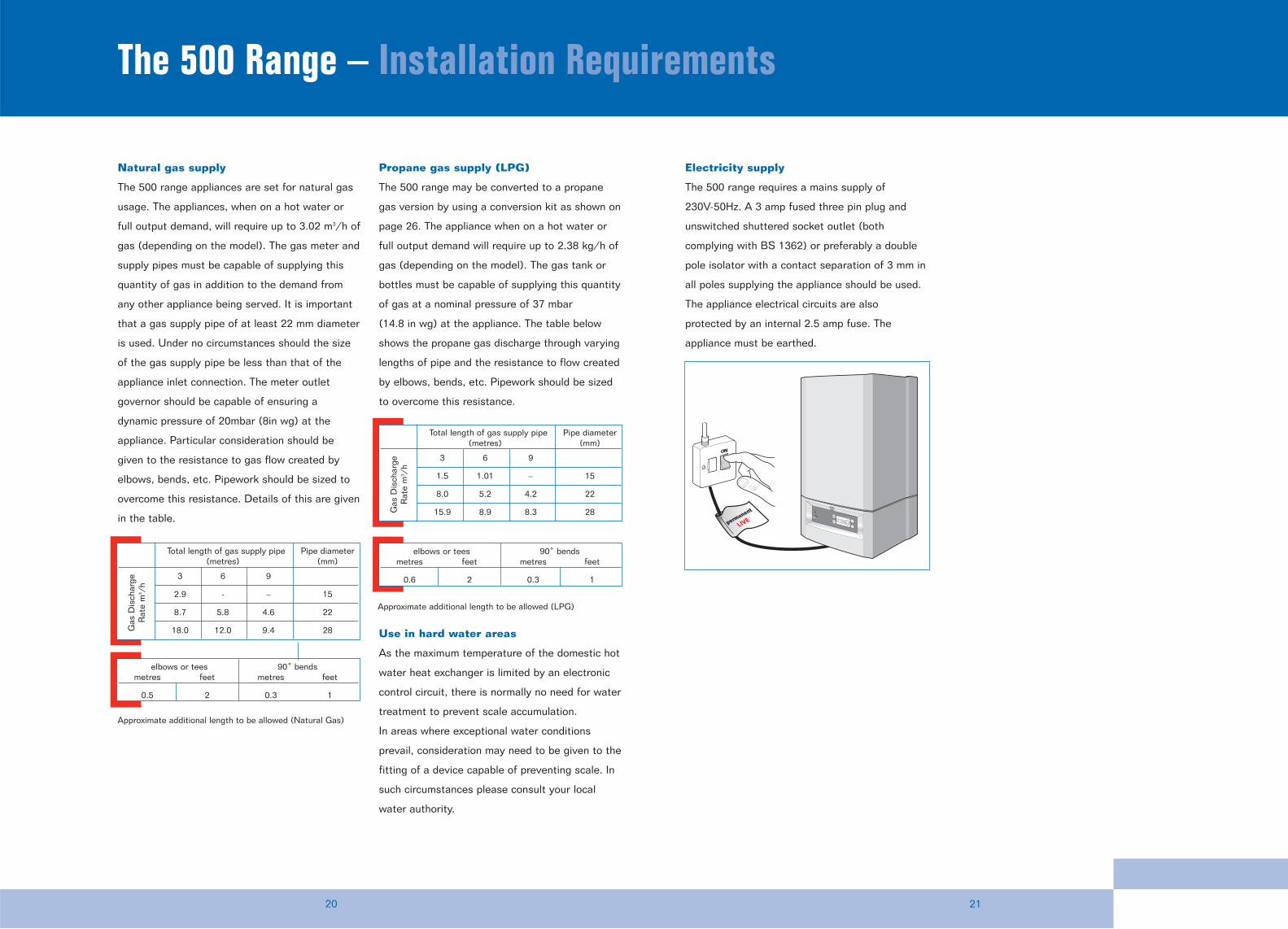
Electricity supply
The 500 range requires a mains supply of
230V-50Hz. A 3 amp fused three pin plug and
unswitched shuttered socket outlet (both
complying with BS 1362) or preferably a double
pole isolator with a contact separation of 3 mm in
all poles supplying the appliance should be used.
The appliance electrical circuits are also
protected by an internal 2.5 amp fuse. The
appliance must be earthed.
Natural gas supply
The 500 range appliances are set for natural gas
usage. The appliances, when on a hot water or
full output demand, will require up to 3.02 m3/h of
gas (depending on the model). The gas meter and
supply pipes must be capable of supplying this
quantity of gas in addition to the demand from
any other appliance being served. It is important
that a gas supply pipe of at least 22 mm diameter
is used. Under no circumstances should the size
of the gas supply pipe be less than that of the
appliance inlet connection. The meter outlet
governor should be capable of ensuring a
dynamic pressure of 20mbar (8in wg) at the
appliance. Particular consideration should be
given to the resistance to gas flow created by
elbows, bends, etc. Pipework should be sized to
overcome this resistance. Details of this are given
in the table.
Propane gas supply (LPG)
The 500 range may be converted to a propane
gas version by using a conversion kit as shown on
page 26. The appliance when on a hot water or
full output demand will require up to 2.38 kg/h of
gas (depending on the model). The gas tank or
bottles must be capable of supplying this quantity
of gas at a nominal pressure of 37 mbar
(14.8 in wg) at the appliance. The table below
shows the propane gas discharge through varying
lengths of pipe and the resistance to flow created
by elbows, bends, etc. Pipework should be sized
to overcome this resistance.
Use in hard water areas
As the maximum temperature of the domestic hot
water heat exchanger is limited by an electronic
control circuit, there is normally no need for water
treatment to prevent scale accumulation.
In areas where exceptional water conditions
prevail, consideration may need to be given to the
fitting of a device capable of preventing scale. In
such circumstances please consult your local
water authority.
2120
The 500 Range – Installation Requirements
Total length of gas supply pipe Pipe diameter(metres) (mm)
3 6 9
1.5 1.01 – 15
8.0 5.2 4.2 22
15.9 8.9 8.3 28Gas
Dis
char
ge
Rat
e m
3 /h
elbows or tees 90˚ bendsmetres feet metres feet
0.6 2 0.3 1
elbows or tees 90˚ bendsmetres feet metres feet
0.5 2 0.3 1
Total length of gas supply pipe Pipe diameter(metres) (mm)
3 6 9
2.9 - – 15
8.7 5.8 4.6 22
18.0 12.0 9.4 28Gas
Dis
char
ge
Rat
e m
3 /h
Approximate additional length to be allowed (LPG)
Approximate additional length to be allowed (Natural Gas)
permanent
LIVE
ON
2322
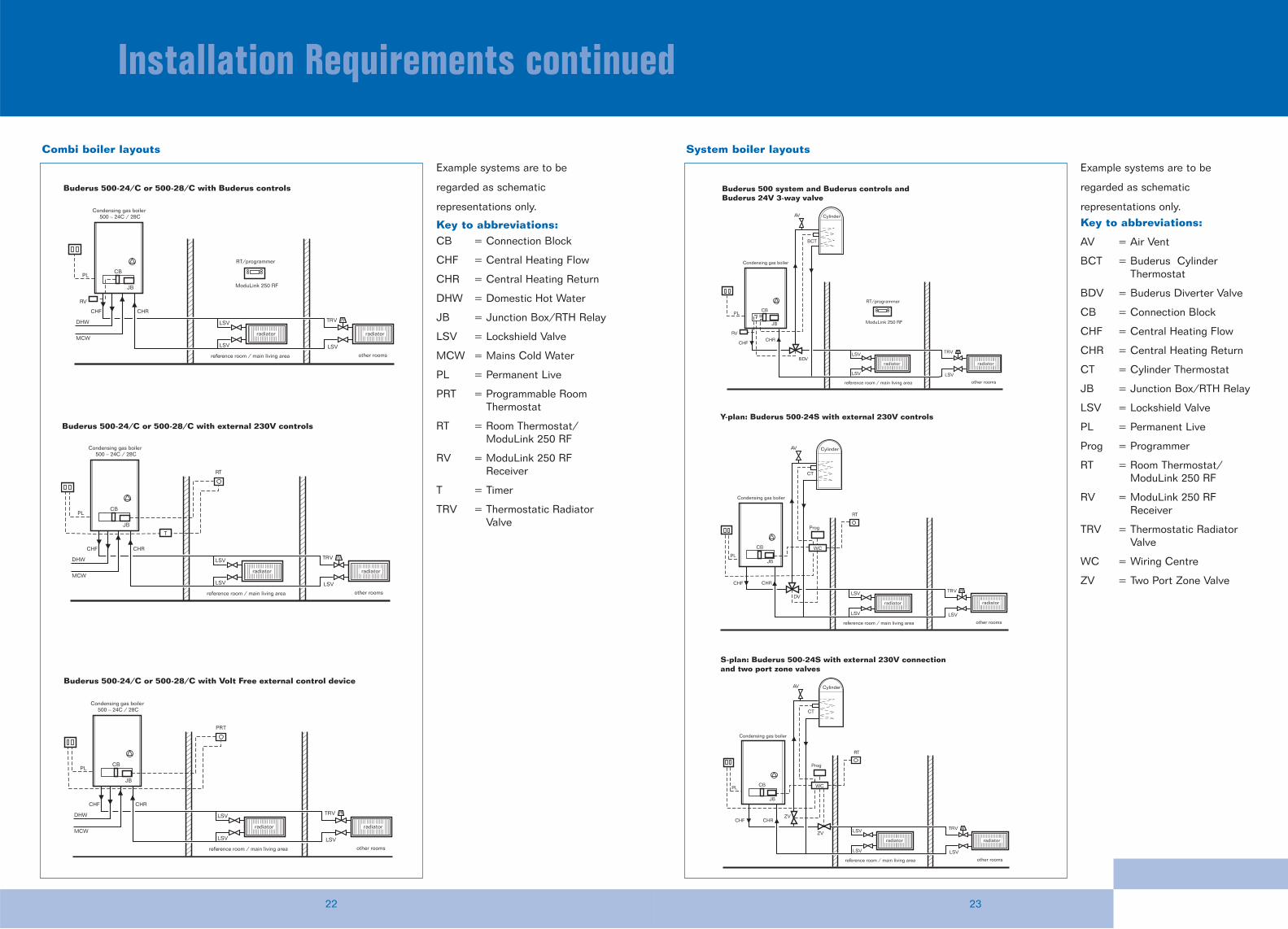
Installation Requirements continued
Buderus 500-24/C or 500-28/C with Buderus controls
ModuLink 250 RF
RT/programmer
reference room / main living area other rooms
Condensing gas boiler500 – 24C / 28C
PL
JB
CB
RV
TRV
LSV
LSV
LSV
radiator radiator
DHW
MCW
CHF CHR
Buderus 500-24/C or 500-28/C with Volt Free external control device
reference room / main living area other rooms
Condensing gas boiler500 – 24C / 28C
JB
CB
TRV
LSV
LSV
LSV
radiator radiator
DHW
MCW
CHF CHR
PRT
Buderus 500-24/C or 500-28/C with external 230V controls
reference room / main living area other rooms
Condensing gas boiler500 – 24C / 28C
JB
CB
TRV
LSV
LSV
LSV
radiator radiator
DHW
MCW
CHF CHR
RT
T
PL
PL
Combi boiler layouts
Example systems are to be
regarded as schematic
representations only.
Key to abbreviations:CB = Connection Block
CHF = Central Heating Flow
CHR = Central Heating Return
DHW = Domestic Hot Water
JB = Junction Box/RTH Relay
LSV = Lockshield Valve
MCW = Mains Cold Water
PL = Permanent Live
PRT = Programmable RoomThermostat
RT = Room Thermostat/ModuLink 250 RF
RV = ModuLink 250 RFReceiver
T = Timer
TRV = Thermostatic RadiatorValve
ModuLink 250 RF
RT/programmer
reference room / main living area other rooms
Condensing gas boiler
PL
JB
CB
RV
BCT
BDV
TRV
LSV
LSV
LSV
Cylinder
radiator radiator
AV
CHFCHR
Buderus 500 system and Buderus controls and Buderus 24V 3-way valve
Prog
reference room / main living area other rooms
Condensing gas boiler
PLJB
CB
CT
DVTRV
LSV
LSV
LSV
Cylinder
radiator
AV
WC
RT
CHF CHR
Y-plan: Buderus 500-24S with external 230V controls
S-plan: Buderus 500-24S with external 230V connection and two port zone valves
Prog
reference room / main living area other rooms
Condensing gas boiler
PL
JB
CB
CT
ZV
TRV
LSV
LSV
LSV
Cylinder
radiator radiator
radiator
AV
RT
CHF CHR
ZV
WC
System boiler layouts
Example systems are to be
regarded as schematic
representations only.Key to abbreviations:
AV = Air Vent
BCT = Buderus CylinderThermostat
BDV = Buderus Diverter Valve
CB = Connection Block
CHF = Central Heating Flow
CHR = Central Heating Return
CT = Cylinder Thermostat
JB = Junction Box/RTH Relay
LSV = Lockshield Valve
PL = Permanent Live
Prog = Programmer
RT = Room Thermostat/ModuLink 250 RF
RV = ModuLink 250 RFReceiver
TRV = Thermostatic RadiatorValve
WC = Wiring Centre
ZV = Two Port Zone Valve
2524
The 500 Range – Controls
Controls
To enable the user to get maximum efficiency
from their condensing boiler it is important that
appropriate heating controls are also fitted.
Buderus has developed a number of heating
control systems to work in harmony with their
range of fully modulating domestic gas
condensing boilers. All controls are designed to
be simple to fit, easy to operate by the user, and
can significantly improve heating comfort levels
and reduce energy usage throughout the home.
Room temperature modulation
All Buderus gas condensing boilers and control
units use a unique and efficient new technology.
This technology, developed by the Buderus Group,
is called “room temperature modulation”. This
energy saving technology controls the output of
the boiler according to the temperature of the air
in the room, rather than measuring the flow
temperature in the boiler. This means the boiler
can react almost instantaneously to even the
smallest temperature fluctuations, adjust its
output accordingly, and maintain comfort levels in
the room.
The temperature in the room will remain constant
and this will result in a more comfortable climate
for the user and fewer trips to the thermostat to
alter the heating output. It also ensures optimal
performance of the boiler as the burner is not
continually turning itself on and off. Only boilers
that modulate using this room temperature
system will be able to achieve this level of
consistency and avoid the larger temperature
fluctuations that can occur using standard
on/off controls.
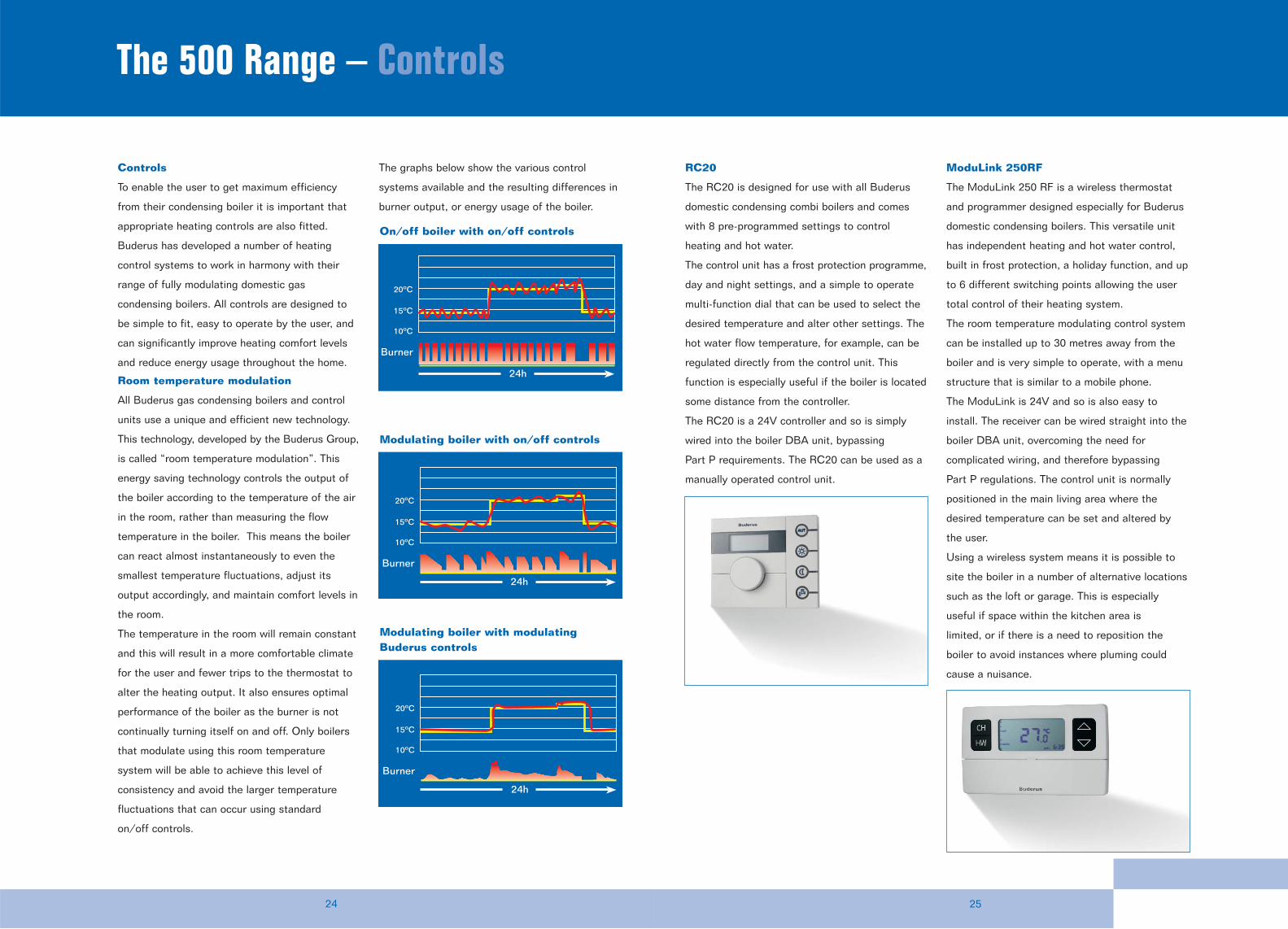
The graphs below show the various control
systems available and the resulting differences in
burner output, or energy usage of the boiler.
RC20
The RC20 is designed for use with all Buderus
domestic condensing combi boilers and comes
with 8 pre-programmed settings to control
heating and hot water.
The control unit has a frost protection programme,
day and night settings, and a simple to operate
multi-function dial that can be used to select the
desired temperature and alter other settings. The
hot water flow temperature, for example, can be
regulated directly from the control unit. This
function is especially useful if the boiler is located
some distance from the controller.
The RC20 is a 24V controller and so is simply
wired into the boiler DBA unit, bypassing
Part P requirements. The RC20 can be used as a
manually operated control unit.
ModuLink 250RF
The ModuLink 250 RF is a wireless thermostat
and programmer designed especially for Buderus
domestic condensing boilers. This versatile unit
has independent heating and hot water control,
built in frost protection, a holiday function, and up
to 6 different switching points allowing the user
total control of their heating system.
The room temperature modulating control system
can be installed up to 30 metres away from the
boiler and is very simple to operate, with a menu
structure that is similar to a mobile phone.
The ModuLink is 24V and so is also easy to
install. The receiver can be wired straight into the
boiler DBA unit, overcoming the need for
complicated wiring, and therefore bypassing
Part P regulations. The control unit is normally
positioned in the main living area where the
desired temperature can be set and altered by
the user.
Using a wireless system means it is possible to
site the boiler in a number of alternative locations
such as the loft or garage. This is especially
useful if space within the kitchen area is
limited, or if there is a need to reposition the
boiler to avoid instances where pluming could
cause a nuisance.
Burner
10ºC
15ºC
20ºC
24h
On/off boiler with on/off controls
Burner
10ºC
15ºC
20ºC
24h
Modulating boiler with on/off controls
Burner
10ºC
15ºC
20ºC
24h
Modulating boiler with modulatingBuderus controls
2726
The 500 Range – Accessories Training with Buderus
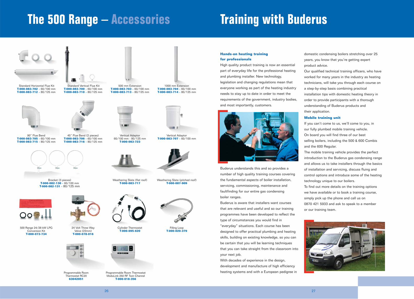
Hands-on heating trainingfor professionals
High quality product training is now an essential
part of everyday life for the professional heating
and plumbing installer. New technology,
legislation and changing regulations mean that
everyone working as part of the heating industry
needs to stay up to date in order to meet the
requirements of the government, industry bodies,
and most importantly, customers.
Buderus understands this and so provides a
number of high quality training courses covering
the fundamental aspects of boiler installation,
servicing, commissioning, maintenance and
faultfinding for our entire gas condensing
boiler ranges.
Buderus is aware that installers want courses
that are relevant and useful and so our training
programmes have been developed to reflect the
type of circumstances you would find in
“everyday” situations. Each course has been
designed to offer practical plumbing and heating
skills, building on existing knowledge, so you can
be certain that you will be learning techniques
that you can take straight from the classroom into
your next job.
With decades of experience in the design,
development and manufacture of high efficiency
heating systems and with a European pedigree in
domestic condensing boilers stretching over 25
years, you know that you’re getting expert
product advice.
Our qualified technical training officers, who have
worked for many years in the industry as heating
technicians, will take you through each course on
a step-by-step basis combining practical
installation tips with domestic heating theory in
order to provide participants with a thorough
understanding of Buderus products and
their application.
Mobile training unit
If you can’t come to us, we’ll come to you, in
our fully plumbed mobile training vehicle.
On board you will find three of our best
selling boilers, including the 500 & 600 Combis
and the 600 Regular.
The mobile training vehicle provides the perfect
introduction to the Buderus gas condensing range
and allows us to take installers through the basics
of installation and servicing, discuss fluing and
control options and introduce some of the heating
technology unique to our boilers.
To find out more details on the training options
we have available or to book a training course,
simply pick up the phone and call us on
0870 421 5933 and ask to speak to a member
or our training team.
Standard Horizontal Flue KitT-000-083-702 - 60/100 mmT-000-083-712 - 80/125 mm
500 mm ExtensionT-000-083-703 - 60/100 mmT-000-083-713 - 80/125 mm
1000 mm ExtensionT-000-083-704 - 60/100 mmT-000-083-714 - 80/125 mm
Bracket (3 pieces)T-000-082-130 - 60/100 mm
T-000-082-131 - 80/125 mm
24 Volt Three WayValve (22mm)
T-000-078-016
Cylinder Thermostat T-000-095-620
Filling LoopT-000-020-379
Programmable Room Thermostat ModuLink 250 RF Twin Channel
T-000-018-356
500 Range 24/28 kW LPGConversion Kit
T-000-073-734
90˚ Flue BendT-000-083-705 - 60/100 mmT-000-083-715 - 80/125 mm
Vertical Adaptor60/100 mm - 80/125 mm
T-000-083-723
45˚ Flue Bend (2 pieces) T-000-083-706 - 60/100 mmT-000-083-716 - 80/125 mm
Weathering Slate (flat roof)T-000-083-717
Weathering Slate (pitched roof)T-000-087-909
Vertical AdaptorT-000-083-707 - 60/100 mm
Standard Vertical Flue KitT-000-083-700 - 60/100 mmT-000-083-710 - 80/125 mm
Programmable RoomThermostat RC20
63042051
To contact us...
Buderus, Cotswold Way, Warndon, Worcester WR4 9SW
Tel: 01905 752936 Fax: 01905 753130
www.buderus-domestic.co.uk
Sales Tel: 01905 752640 Fax: 01905 456445/455394
Returns Tel: 01905 752531 Fax: 01905 455392
Spares Tel: 01905 752576 Fax: 01905 754620
Customer Service Tel: 0870 421 5933
Technical Product Support Tel: 0870 421 5944
In the UK, Buderus is a trading name of BBT Thermotechnology UK Ltd.
Buderus’ policy is one of continuous research and development and this may necessitate alterationsto this specification from time to time. Therefore before preparing for the installation of theappliance it is important that the instructions issued with the unit are carefully read and adhered to.The statutory rights of the customer are not affected. All information is correct at time of going topress. Buderus reserves the right to alter any information where necessary. E&OE. 8 716 110 999 ISSUE A 02/06