Embed Size (px)
Citation preview
Intel® Server Systems SR1530AH, SR1530AHLX and SR1530HAHLX
Technical Product Specification
Intel order number D77400-004
Revision 1.3
April 2008
Enterprise Platforms and Services Division - Marketing

Revision History Intel® Server Systems SR1530AH, SR1530AHLX and SR1530HAHLX
Intel order number D77400-004 Revision 1.3 ii
Revision History
Date Revision Number
Modifications
November 2006 1.0 Initial release. January 2007 1.1 Added hot-swap version of the system. October 2007 1.2 Add “Environmental altitude operation specification” April 2008 1.3 Add Reference documents and correct error
Disclaimers Information in this document is provided in connection with Intel® products. No license, express or implied, by estoppel or otherwise, to any intellectual property rights is granted by this document. Except as provided in Intel's Terms and Conditions of Sale for such products, Intel assumes no liability whatsoever, and Intel disclaims any express or implied warranty, relating to sale and/or use of Intel products including liability or warranties relating to fitness for a particular purpose, merchantability, or infringement of any patent, copyright or other intellectual property right. Intel products are not intended for use in medical, life saving, or life sustaining applications. Intel may make changes to specifications and product descriptions at any time, without notice.
Designers must not rely on the absence or characteristics of any features or instructions marked "reserved" or "undefined." Intel reserves these for future definition and shall have no responsibility whatsoever for conflicts or incompatibilities arising from future changes to them.
This document contains information on products in the design phase of development. Do not finalize a design with this information. Revised information will be published when the product is available. Verify with your local sales office that you have the latest datasheet before finalizing a design.
The server boards / chassis referenced in this document may contain design defects or errors known as errata which may cause the product to deviate from published specifications. Current characterized errata are available on request.
Intel, Pentium, Itanium, and Xeon are trademarks or registered trademarks of Intel Corporation.
*Other brands and names may be claimed as the property of others.
Copyright © Intel Corporation 2007 - 2008. All rights reserved.
Intel® Server Systems SR1530AH, SR1530AHLX and SR1530HAHLX Table of Contents
Revision 1.3 Intel order number D77400-004 iii
Table of Contents
1. Introduction .......................................................................................................................... 1 1.1 System Views .......................................................................................................... 1 1.2 Chassis Dimensions ................................................................................................ 2 1.3 System Components ............................................................................................... 3 1.4 System Boards ........................................................................................................ 5
1.4.1 Intel® Server System SR1530AHLX ........................................................................ 5 1.4.2 Intel® Server System SR1530AH............................................................................. 6 1.4.3 Intel® Server System SR1530HAHLX...................................................................... 6
1.5 Hard Drive and Peripheral Bays .............................................................................. 7 1.6 System Cooling........................................................................................................ 8 1.7 Rack and Cabinet Mounting Options ....................................................................... 8
2. Power Sub-System...............................................................................................................9 2.1 Mechanical Specifications ..................................................................................... 10 2.2 Output Connectors................................................................................................. 11
2.2.1 Baseboard power connector (P1) .......................................................................... 12 2.2.2 Processor Power Connector (P2) .......................................................................... 12 2.2.3 SATA Hard Drive Power Connectors (P4, P5)....................................................... 13 2.2.4 CDROM Power Connector (P6)............................................................................. 13 2.2.5 Intel® Server System SR1530HAHLX P7 Hot-swap Backplane Power Connector 13
2.3 AC Inlet Connector ................................................................................................ 13 2.3.1 AC Power Cord Specification Requirements ......................................................... 14
2.4 Marking and Identification...................................................................................... 14 2.5 AC Input Voltage.................................................................................................... 14 2.6 Output Power / Currents ........................................................................................ 15 2.7 Protection Circuits.................................................................................................. 15 2.8 Over Current Protection (OCP).............................................................................. 15 2.9 Over-Voltage Protection (OVP) ............................................................................. 16 2.10 Over-Temperature Protection (OTP) ..................................................................... 16
3. Cooling Sub-System .......................................................................................................... 17 3.1 Power Supply Fans................................................................................................ 18 3.2 CPU Air Duct ......................................................................................................... 19
4. Peripheral and Hard Drive Support................................................................................... 21
Table of Contents Intel® Server Systems SR1530AH, SR1530AHLX and SR1530HAHLX
Intel order number D77400-004 Revision 1.3 iv
4.1 Optical Drive Support............................................................................................. 21 4.1.1 Optical Drive Support............................................................................................. 22
4.2 Hard Disk Drive Support ........................................................................................ 22 4.2.1 System Fan Connectors ........................................................................................ 23
5. Front Control Panel............................................................................................................24 5.1.1 Power / Sleep LED ................................................................................................ 26 5.1.2 System Status LED................................................................................................ 26 5.1.3 Drive Activity LED .................................................................................................. 26
6. PCI Riser Cards and Assembly......................................................................................... 27 7. Intel® Server System SR1530HAHLX Passive SAS/SATA Hot-swap Backplane .......... 29
7.1.1 Hot-swap Drive Trays ............................................................................................ 31 8. Supported Intel® Server Boards........................................................................................ 32 9. Environmental and Regulatory Specifications................................................................ 33
9.1 System Level Environmental Limits ....................................................................... 33 9.2 Product Regulatory Compliance ............................................................................ 33
9.2.1 Product Safety Compliance ................................................................................... 33 9.2.2 Product EMC Compliance ..................................................................................... 34 9.2.3 Certifications / Registrations / Declarations ........................................................... 34 9.2.4 Product Regulatory Compliance Markings ............................................................ 35
9.3 Electromagnetic Compatibility Notices .................................................................. 37 9.3.1 USA ....................................................................................................................... 37 9.3.2 FCC Verification Statement ................................................................................... 37 9.3.3 ICES-003 (Canada) ............................................................................................... 38 9.3.4 Europe (CE Declaration of Conformity) ................................................................. 38 9.3.5 Japan EMC Compatibility ...................................................................................... 38 9.3.6 BSMI (Taiwan) ....................................................................................................... 38 9.3.7 RRL (Korea)........................................................................................................... 39 9.3.8 CNCA (CCC-China) ............................................................................................... 39
9.4 Replacing the Back up Battery .............................................................................. 40 9.5 Serviceability and Availability................................................................................. 41
9.5.1 Product Ecology Requirements ............................................................................. 41 9.6 Restriction of Hazardous Substances (RoHS) Compliance................................... 42 9.7 Regulated Specified Components ......................................................................... 43 9.8 Environmental altitude operation specification ...................................................... 43
Appendix A: Integration and Usage Tips................................................................................... I
Intel® Server Systems SR1530AH, SR1530AHLX and SR1530HAHLX Table of Contents
Revision 1.3 Intel order number D77400-004 v
Appendix B: POST Code Diagnostic LED Decoder ................................................................. II Appendix C: POST Error Beep Codes......................................................................................VI Glossary.....................................................................................................................................VII Reference Documents .............................................................................................................VIII
List of Figures Intel® Server Systems SR1530AH, SR1530AHLX and SR1530HAHLX
Intel order number D77400-004 Revision 1.3 vi
List of Figures
Figure 1. Intel® Server Systems SR1530AH / SR1530AHLX........................................................ 1 Figure 2. Intel® Server System SR1530HAHLX............................................................................ 2 Figure 3. Intel® Server Systems SR1530AH / SR1530AHLX Major System Components ........... 3 Figure 4. Intel® Server System SR1530HAHLX Major System Components................................ 4 Figure 5. Back Panel Features ..................................................................................................... 5 Figure 6. Intel® Server Systems SR1530AH / SR1530AHLX Drive Bays ..................................... 7 Figure 7. Intel® Server System SR1530HAHLX Drive Bays ......................................................... 8 Figure 8. Power Supply Enclosure Drawing ............................................................................... 10 Figure 9. Intel® Server Systems SR1530AH / SR1530AHLX Fan Module Assembly ................. 17 Figure 10. Intel® Server Systems SR1530AH / SR1530AHLX Air Duct ...................................... 19 Figure 11. Intel® Server System SR1530HAHLX Air Duct .......................................................... 20 Figure 12. Drive Bays ................................................................................................................. 21 Figure 13. Intel® Server Systems SR1530AH / SR1530AHLX Front Control Panel ................... 24 Figure 14. Intel® Server System SR1530HAHLX Front Control Panel........................................ 25 Figure 15. PCI Riser Card Assembly .......................................................................................... 27 Figure 16. 1U PCI-X* Riser Card Mechanical Drawing............................................................... 27 Figure 17. 1U PCIe* Riser Card Mechanical Drawing ................................................................ 28 Figure 18. Intel® Server System SR1530HAHLX Hot-swap Backplane...................................... 29 Figure 19. Hard Drive Tray Assembly......................................................................................... 31 Figure 20. Diagnostic LED Placement Diagram Example ............................................................ II
Intel® Server Systems SR1530AH, SR1530AHLX and SR1530HAHLX List of Tables
Revision 1.3 Intel order number D77400-004 vii
List of Tables
Table 1. Intel® Server Systems SR1530AH / SR1530AHLX Dimensions ..................................... 2 Table 2. Intel® Server System SR1530HAHLX Dimensions ......................................................... 3 Table 3. Intel® Server Systems SR1530AH / SR1530AHLX Cable Lengths............................... 11 Table 4. Intel® Server System SR1530HAHLX Cable Lengths................................................... 11 Table 5. P1 Main Power Connector ........................................................................................... 12 Table 6. P2 Processor Power Connector................................................................................... 12 Table 7. HD Power Connector ...................................................................................................13 Table 8. CD-ROM Power Connector ......................................................................................... 13 Table 9. P7 HSBP Power Connector ......................................................................................... 13 Table 10. AC Input Rating........................................................................................................... 14 Table 11. Load Ratings.............................................................................................................. 15 Table 12. Over Current Protection (OCP)................................................................................... 15 Table 13. Over-Voltage Protection (OVP) Limits ........................................................................ 16 Table 14. Intel® Server Systems SR1530AH / SR1530AHLX Cooling Zones............................. 18 Table 15. Intel® Server System SR1530HAHLX Cooling Zones................................................. 18 Table 16. 40-pin Internal IDE Connector Pin-out (J3J2) ............................................................. 22 Table 17. System Four-pin Fan Headers Pin-outs (J7J1, J8D1, J4J1, and J6B1, J6J1)............ 23 Table 18. Control Panel LED Functions...................................................................................... 25 Table 19. SSI Power LED Operation .......................................................................................... 26 Table 20. Passive SATA/SAS Backplane Power Connector Pin-out (J7)................................... 30 Table 21. Passive SATA/SAS Backplane Connector to Hard Drive Pin-out (J1, J2, J3) ............ 30 Table 22. Passive SATA/SAS Backplane I/O Connector to Baseboard Pin-out (J4, J5, J6) ...... 31 Table 23. System Environmental Limits Summary ..................................................................... 33 Table 24. POST Progress Code LED Example ............................................................................ II Table 25. Diagnostic LED POST Code Decoder ......................................................................... III Table 26. POST Error Beep Codes .............................................................................................VI

Intel® Server Systems SR1530AH, SR1530AHLX and SR1530HAHLX Introduction
Revision 1.3 Intel order number D77400-004 1
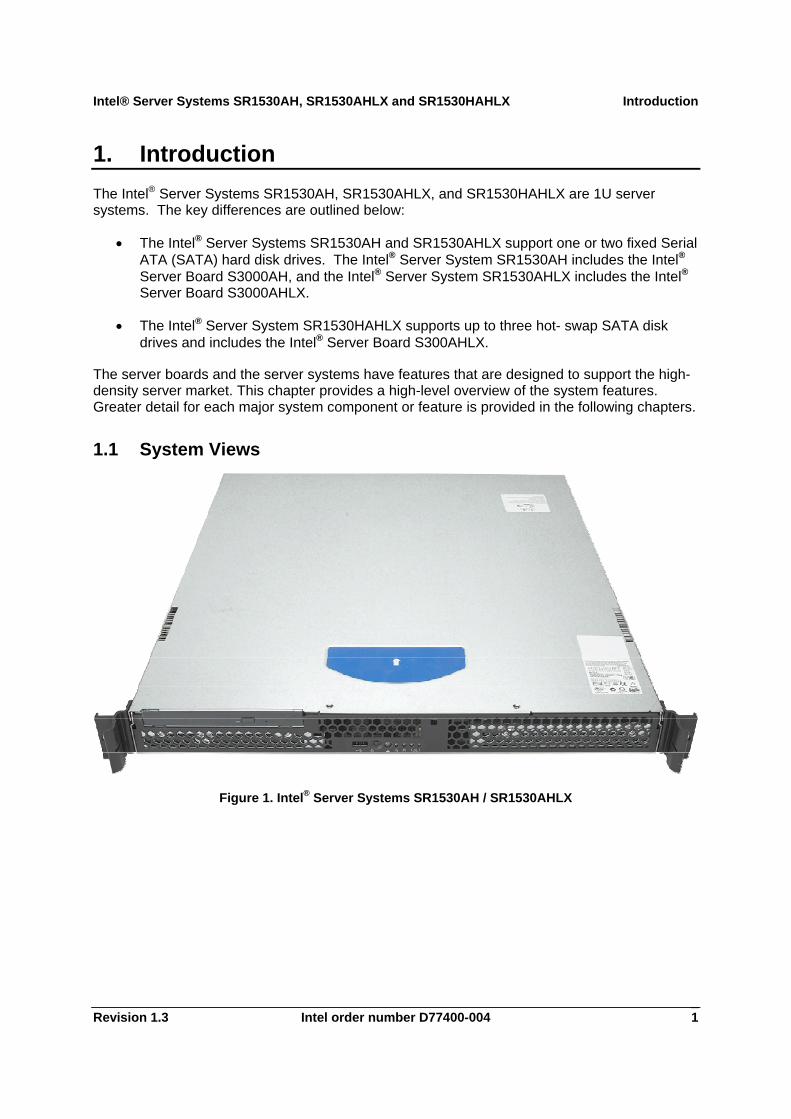
1. Introduction The Intel® Server Systems SR1530AH, SR1530AHLX, and SR1530HAHLX are 1U server systems. The key differences are outlined below:
• The Intel® Server Systems SR1530AH and SR1530AHLX support one or two fixed Serial ATA (SATA) hard disk drives. The Intel® Server System SR1530AH includes the Intel® Server Board S3000AH, and the Intel® Server System SR1530AHLX includes the Intel® Server Board S3000AHLX.
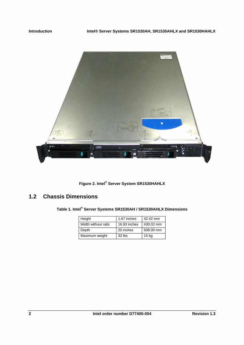
• The Intel® Server System SR1530HAHLX supports up to three hot- swap SATA disk drives and includes the Intel® Server Board S300AHLX.
The server boards and the server systems have features that are designed to support the high-density server market. This chapter provides a high-level overview of the system features. Greater detail for each major system component or feature is provided in the following chapters.
1.1 System Views
Figure 1. Intel® Server Systems SR1530AH / SR1530AHLX
Introduction Intel® Server Systems SR1530AH, SR1530AHLX and SR1530HAHLX
Intel order number D77400-004 Revision 1.3 2
Figure 2. Intel® Server System SR1530HAHLX
1.2 Chassis Dimensions
Table 1. Intel® Server Systems SR1530AH / SR1530AHLX Dimensions
Height 1.67 inches 42.42 mm Width without rails 16.93 inches 430.02 mm Depth 20 inches 508.00 mm Maximum weight 33 lbs 15 kg
Intel® Server Systems SR1530AH, SR1530AHLX and SR1530HAHLX Introduction
Revision 1.3 Intel order number D77400-004 3
AF000970
A
C
D
B
F
E
GH
I
K
A
J
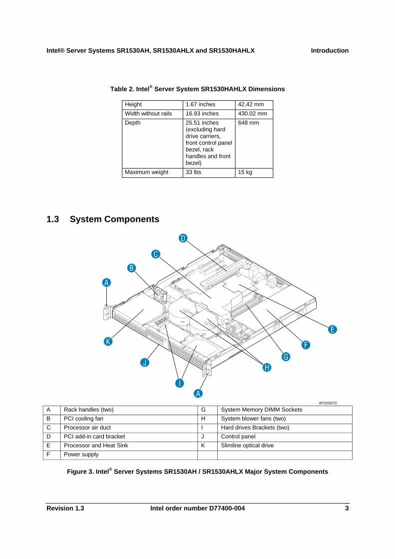
Table 2. Intel® Server System SR1530HAHLX Dimensions
Height 1.67 inches 42.42 mm Width without rails 16.93 inches 430.02 mm Depth 25.51 inches
(excluding hard drive carriers, front control panel bezel, rack handles and front bezel)
648 mm
Maximum weight 33 lbs 15 kg
1.3 System Components
A Rack handles (two) G System Memory DIMM Sockets B PCI cooling fan H System blower fans (two) C Processor air duct I Hard drives Brackets (two) D PCI add-in card bracket J Control panel E Processor and Heat Sink K Slimline optical drive F Power supply
Figure 3. Intel® Server Systems SR1530AH / SR1530AHLX Major System Components
Introduction Intel® Server Systems SR1530AH, SR1530AHLX and SR1530HAHLX
Intel order number D77400-004 Revision 1.3 4
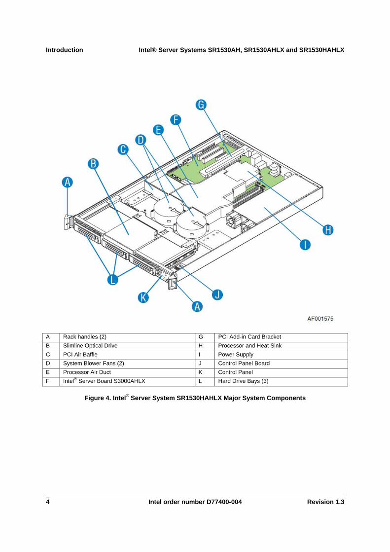
A Rack handles (2) G PCI Add-in Card Bracket B Slimline Optical Drive H Processor and Heat Sink C PCI Air Baffle I Power Supply D System Blower Fans (2) J Control Panel Board E Processor Air Duct K Control Panel F Intel® Server Board S3000AHLX L Hard Drive Bays (3)
Figure 4. Intel® Server System SR1530HAHLX Major System Components
Intel® Server Systems SR1530AH, SR1530AHLX and SR1530HAHLX Introduction
Revision 1.3 Intel order number D77400-004 5
A B C D E
GI H FAF000999
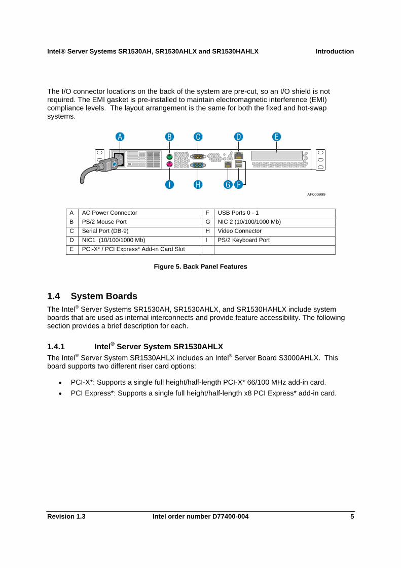
The I/O connector locations on the back of the system are pre-cut, so an I/O shield is not required. The EMI gasket is pre-installed to maintain electromagnetic interference (EMI) compliance levels. The layout arrangement is the same for both the fixed and hot-swap systems.
A AC Power Connector F USB Ports 0 - 1 B PS/2 Mouse Port G NIC 2 (10/100/1000 Mb) C Serial Port (DB-9) H Video Connector D NIC1 (10/100/1000 Mb) I PS/2 Keyboard Port E PCI-X* / PCI Express* Add-in Card Slot
Figure 5. Back Panel Features
1.4 System Boards The Intel® Server Systems SR1530AH, SR1530AHLX, and SR1530HAHLX include system boards that are used as internal interconnects and provide feature accessibility. The following section provides a brief description for each.
1.4.1 Intel® Server System SR1530AHLX The Intel® Server System SR1530AHLX includes an Intel® Server Board S3000AHLX. This board supports two different riser card options:
• PCI-X*: Supports a single full height/half-length PCI-X* 66/100 MHz add-in card. • PCI Express*: Supports a single full height/half-length x8 PCI Express* add-in card.

Introduction Intel® Server Systems SR1530AH, SR1530AHLX and SR1530HAHLX
Intel order number D77400-004 Revision 1.3 6
1.4.2 Intel® Server System SR1530AH The Intel® Server System SR1530AH includes an Intel® Server Board S3000AH. This board supports a PCI Express* riser card which is capable of supporting a single full height/half-length x8 PCI Express* add-in card.
The Intel® Server Systems SR1530AH and SR1530AHLX include a front control panel. The front control panel is a printed circuit board routing the outputs of the system board SSI connector to provide a power on/off switch, a power on/off LED, a Hard Disk Drive activity LED, NIC 1 and NIC 2 activity LEDs, and USB port 2.
1.4.3 Intel® Server System SR1530HAHLX The Intel® Server System SR1530HAHLX is only available with the Intel® Server Board S3000AHLX. This board supports two different riser card options:
• PCI-X*: Supports a single full height/full-length PCI-X* 66/100 MHz add-in card. • PCI Express*: Supports a single full height/full-length x8 PCI Express* add-in card.
Intel® Server Systems SR1530AH, SR1530AHLX and SR1530HAHLX Introduction
Revision 1.3 Intel order number D77400-004 7
AF001074C
AB
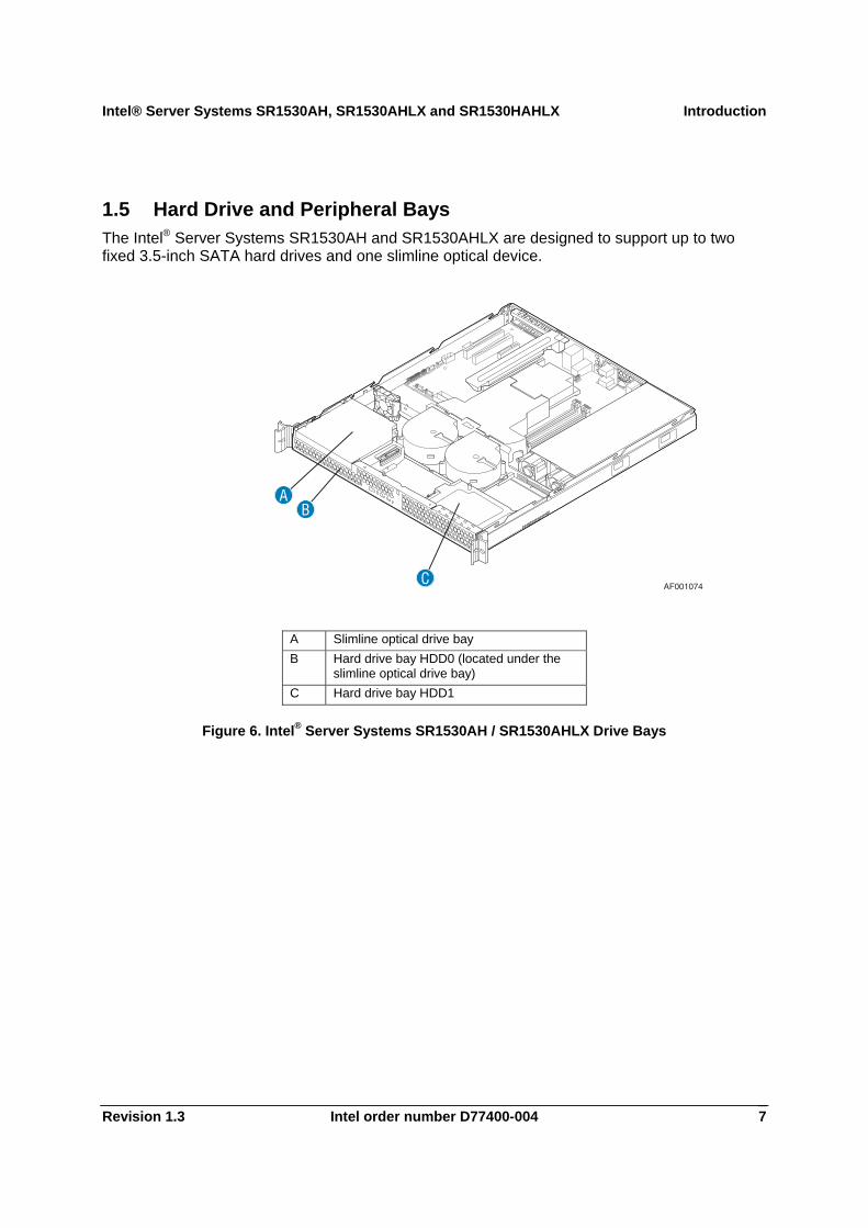
1.5 Hard Drive and Peripheral Bays The Intel® Server Systems SR1530AH and SR1530AHLX are designed to support up to two fixed 3.5-inch SATA hard drives and one slimline optical device.
A Slimline optical drive bay B Hard drive bay HDD0 (located under the
slimline optical drive bay) C Hard drive bay HDD1
Figure 6. Intel® Server Systems SR1530AH / SR1530AHLX Drive Bays
Introduction Intel® Server Systems SR1530AH, SR1530AHLX and SR1530HAHLX
Intel order number D77400-004 Revision 1.3 8
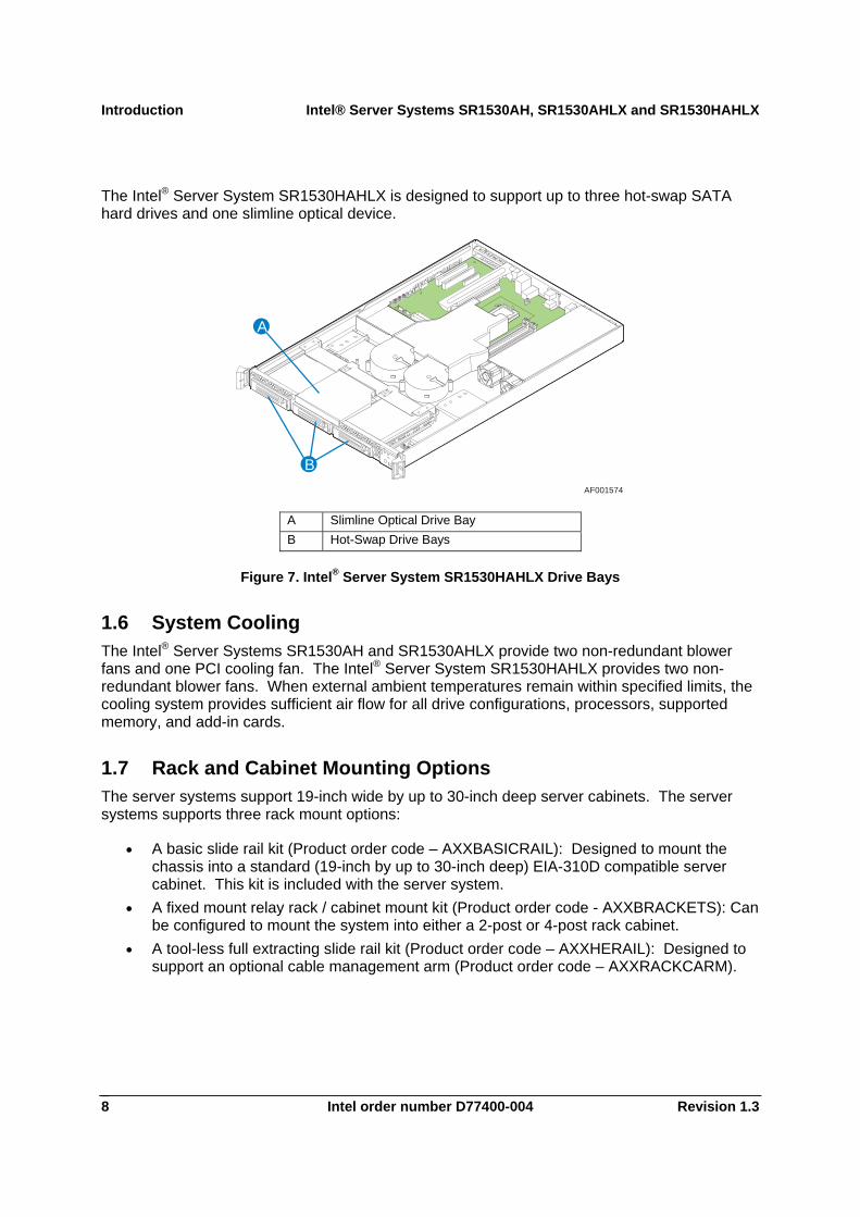
The Intel® Server System SR1530HAHLX is designed to support up to three hot-swap SATA hard drives and one slimline optical device.
AF001574
B
A
A Slimline Optical Drive Bay B Hot-Swap Drive Bays
Figure 7. Intel® Server System SR1530HAHLX Drive Bays
1.6 System Cooling The Intel® Server Systems SR1530AH and SR1530AHLX provide two non-redundant blower fans and one PCI cooling fan. The Intel® Server System SR1530HAHLX provides two non-redundant blower fans. When external ambient temperatures remain within specified limits, the cooling system provides sufficient air flow for all drive configurations, processors, supported memory, and add-in cards.
1.7 Rack and Cabinet Mounting Options The server systems support 19-inch wide by up to 30-inch deep server cabinets. The server systems supports three rack mount options:
• A basic slide rail kit (Product order code – AXXBASICRAIL): Designed to mount the chassis into a standard (19-inch by up to 30-inch deep) EIA-310D compatible server cabinet. This kit is included with the server system.
• A fixed mount relay rack / cabinet mount kit (Product order code - AXXBRACKETS): Can be configured to mount the system into either a 2-post or 4-post rack cabinet.
• A tool-less full extracting slide rail kit (Product order code – AXXHERAIL): Designed to support an optional cable management arm (Product order code – AXXRACKCARM).
Intel® Server Systems SR1530AH, SR1530AHLX and SR1530HAHLX Power Sub-System
Revision 1.3 Intel order number D77400-004 9
2. Power Sub-System The power sub-system of the server systems consist of a single non-redundant 350 W power supply with 5 outputs; 3.3V, 5V, 12V, and 5VSB. The form factor fits into a 1U system and provides a wire harness output to the system. An IEC connector is provided on the external face for AC input to the power supply. The power supply provides two non-redundant 40mm fans for self cooling. The power supply fans also provide additional airflow.
The power supply operates within the following voltage ranges and ratings:
Parameter Minimum Rated Maximum Start up VAC Power Off VAC Voltage (110) 90 Vrms 100-127 Vrms 140 Vrms 85Vac +/-4Vac 75Vac +/-5Vac Voltage (220) 180 Vrms 200-240 Vrms 264 Vrms Frequency 47 Hz 63 Hz
The power supply must operate within all specified limits over the following input voltage range, shown in the table. Harmonic distortion of up to 10% THD will not cause the power supply to go out of specified limits. The power supply will power off if the AC input is less than 75VAC +/-5VAC range. The power supply will start up if the AC input is greater than 85VAC +/-4VAC. Application of an input voltage below 85VAC will damage the power supply, including a fuse blow.
Power Sub-System Intel® Server Systems SR1530AH, SR1530AHLX and SR1530HAHLX
Intel order number D77400-004 Revision 1.3 10
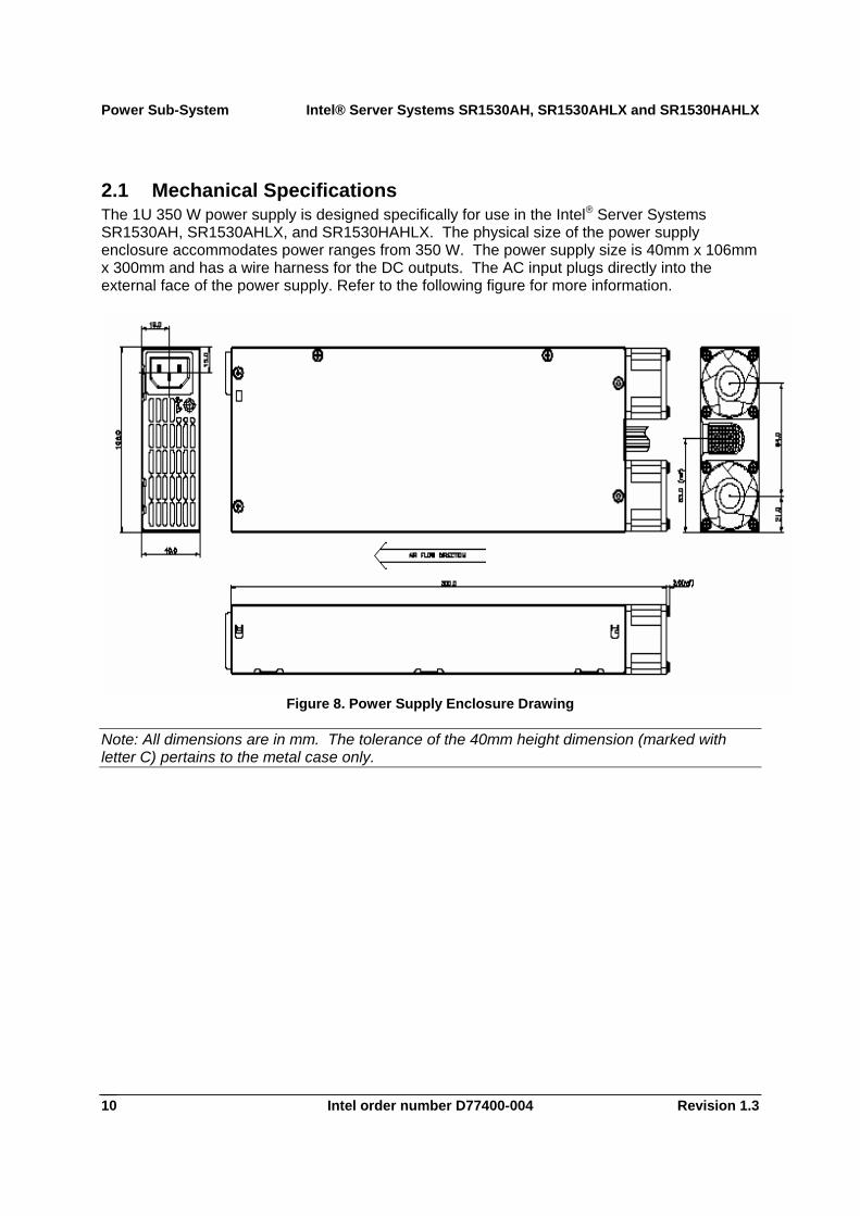
2.1 Mechanical Specifications The 1U 350 W power supply is designed specifically for use in the Intel® Server Systems SR1530AH, SR1530AHLX, and SR1530HAHLX. The physical size of the power supply enclosure accommodates power ranges from 350 W. The power supply size is 40mm x 106mm x 300mm and has a wire harness for the DC outputs. The AC input plugs directly into the external face of the power supply. Refer to the following figure for more information.
Figure 8. Power Supply Enclosure Drawing
Note: All dimensions are in mm. The tolerance of the 40mm height dimension (marked with letter C) pertains to the metal case only.

Intel® Server Systems SR1530AH, SR1530AHLX and SR1530HAHLX Power Sub-System
Revision 1.3 Intel order number D77400-004 11
2.2 Output Connectors Listed or recognized component appliance wiring material (AVLV2), CN, rated min 80°C, 300VDC must be used for all output wiring.
Table 3. Intel® Server Systems SR1530AH / SR1530AHLX Cable Lengths
From Length (mm)
To connector
# Description
Power Supply cover exit hole 380 P1 Baseboard Power Connector Power Supply cover exit hole 390 P2 Processor Power Connector Power Supply cover exit hole 495 P3 HD Power Connector Power Supply cover exit hole 605 P4 HD Power Connector Power Supply cover exit hole 860 P5 Slimline Power Connector
Table 4. Intel® Server System SR1530HAHLX Cable Lengths
From Length (mm)
To connector
# Description
Power Supply cover exit hole 400 P1 Baseboard Power Connector Power Supply cover exit hole 380 P2 Processor Power Connector Power Supply cover exit hole 220 P7 2 x 4 HSBP power connector P7 100 P4 SATA Drive Power Connector P4 145 P5 SATA Drive Power Connector P5 170 P6 CD-ROM Power Connector

Power Sub-System Intel® Server Systems SR1530AH, SR1530AHLX and SR1530HAHLX
Intel order number D77400-004 Revision 1.3 12
2.2.1 Baseboard power connector (P1) Connector housing: 20-Pin Molex* Mini-Fit Jr. 39-01-2200 or equivalent. Contact: Molex Mini-Fit, HCS, female, crimp 44476 or Molex 5556 as the alternative, or equivalent approved by Intel.
Table 5. P1 Main Power Connector
Pin Signal 18 AWG Color Pin Signal 18 AWG Color 1* +3.3VDC Orange 11 +3.3VDC Orange 3.3V RS Orange/White (24AWG) 12 -12VDC Blue
2 +3.3VDC Orange 13 COM Black 3 COM Black 14 PSON# Green (24AWG) 4 +5VDC Red 15* COM Black 5 COM Black COMRS Black (24AWG) 6 +5VDC Red 16 COM Black 7 COM Black 17 COM Black 8 PWR OK Gray (24AWG) 18 Reserved N.C. 9 5 VSB Purple 19 +5VDC Red
10* +12V Yellow 20* +5VDC Red 12VRS Yellow/White (24AWG) 5VRS Red/White (24AWG)
Notes: The Remote Sense wire is double crimped. The P1 add cable bend requirement is at P1.
2.2.2 Processor Power Connector (P2) Connector housing: 8-Pin Molex 39-01-2085 or equivalent. Contact: 44476-1111 or Molex 5556 as the alternative, or equivalent.
Table 6. P2 Processor Power Connector
Pin Signal 18 AWG color Pin Signal 18 AWG Color 1 COM Black 5 +12V Yellow 2 COM Black 6 +12V Yellow 3 N.C. 7 N.C. 4 N.C. 8 N.C.
Intel® Server Systems SR1530AH, SR1530AHLX and SR1530HAHLX Power Sub-System
Revision 1.3 Intel order number D77400-004 13
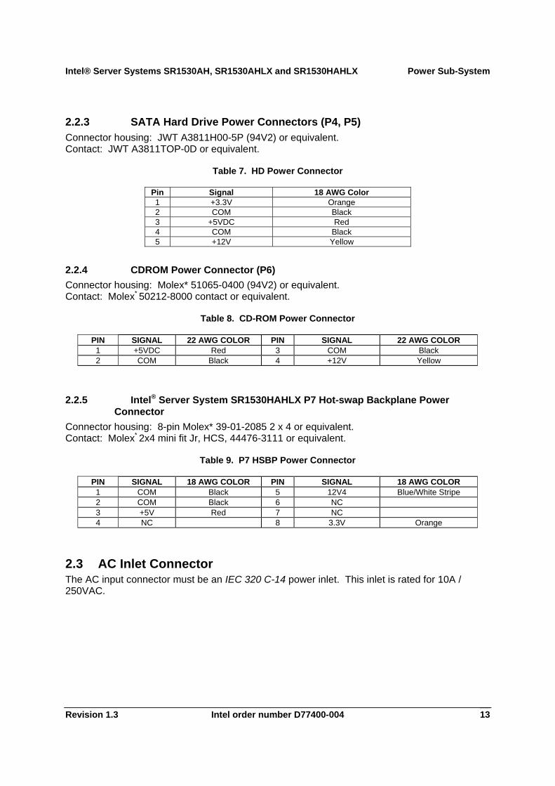
2.2.3 SATA Hard Drive Power Connectors (P4, P5) Connector housing: JWT A3811H00-5P (94V2) or equivalent. Contact: JWT A3811TOP-0D or equivalent.
Table 7. HD Power Connector
Pin Signal 18 AWG Color 1 +3.3V Orange 2 COM Black 3 +5VDC Red 4 COM Black 5 +12V Yellow
2.2.4 CDROM Power Connector (P6) Connector housing: Molex* 51065-0400 (94V2) or equivalent. Contact: Molex* 50212-8000 contact or equivalent.
Table 8. CD-ROM Power Connector
PIN SIGNAL 22 AWG COLOR PIN SIGNAL 22 AWG COLOR 1 +5VDC Red 3 COM Black 2 COM Black 4 +12V Yellow
2.2.5 Intel® Server System SR1530HAHLX P7 Hot-swap Backplane Power Connector
Connector housing: 8-pin Molex* 39-01-2085 2 x 4 or equivalent. Contact: Molex* 2x4 mini fit Jr, HCS, 44476-3111 or equivalent.
Table 9. P7 HSBP Power Connector
PIN SIGNAL 18 AWG COLOR PIN SIGNAL 18 AWG COLOR 1 COM Black 5 12V4 Blue/White Stripe 2 COM Black 6 NC 3 +5V Red 7 NC 4 NC 8 3.3V Orange
2.3 AC Inlet Connector The AC input connector must be an IEC 320 C-14 power inlet. This inlet is rated for 10A / 250VAC.
Power Sub-System Intel® Server Systems SR1530AH, SR1530AHLX and SR1530HAHLX
Intel order number D77400-004 Revision 1.3 14
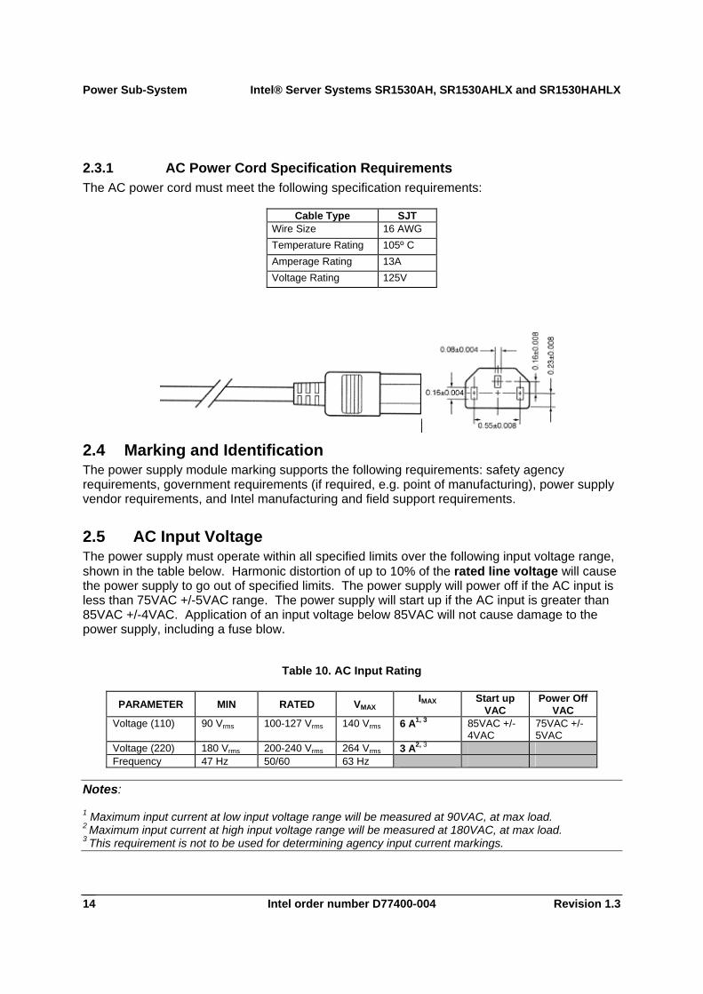
2.3.1 AC Power Cord Specification Requirements The AC power cord must meet the following specification requirements:
Cable Type SJT Wire Size 16 AWG Temperature Rating 105º C Amperage Rating 13A Voltage Rating 125V
2.4 Marking and Identification The power supply module marking supports the following requirements: safety agency requirements, government requirements (if required, e.g. point of manufacturing), power supply vendor requirements, and Intel manufacturing and field support requirements.
2.5 AC Input Voltage The power supply must operate within all specified limits over the following input voltage range, shown in the table below. Harmonic distortion of up to 10% of the rated line voltage will cause the power supply to go out of specified limits. The power supply will power off if the AC input is less than 75VAC +/-5VAC range. The power supply will start up if the AC input is greater than 85VAC +/-4VAC. Application of an input voltage below 85VAC will not cause damage to the power supply, including a fuse blow.
Table 10. AC Input Rating
PARAMETER MIN RATED VMAX IMAX
Start up VAC
Power Off VAC
Voltage (110) 90 Vrms 100-127 Vrms 140 Vrms 6 A1, 3 85VAC +/-4VAC
75VAC +/-5VAC
Voltage (220) 180 Vrms 200-240 Vrms 264 Vrms 3 A2, 3 Frequency 47 Hz 50/60 63 Hz
Notes:
1 Maximum input current at low input voltage range will be measured at 90VAC, at max load. 2 Maximum input current at high input voltage range will be measured at 180VAC, at max load. 3 This requirement is not to be used for determining agency input current markings.
Intel® Server Systems SR1530AH, SR1530AHLX and SR1530HAHLX Power Sub-System
Revision 1.3 Intel order number D77400-004 15
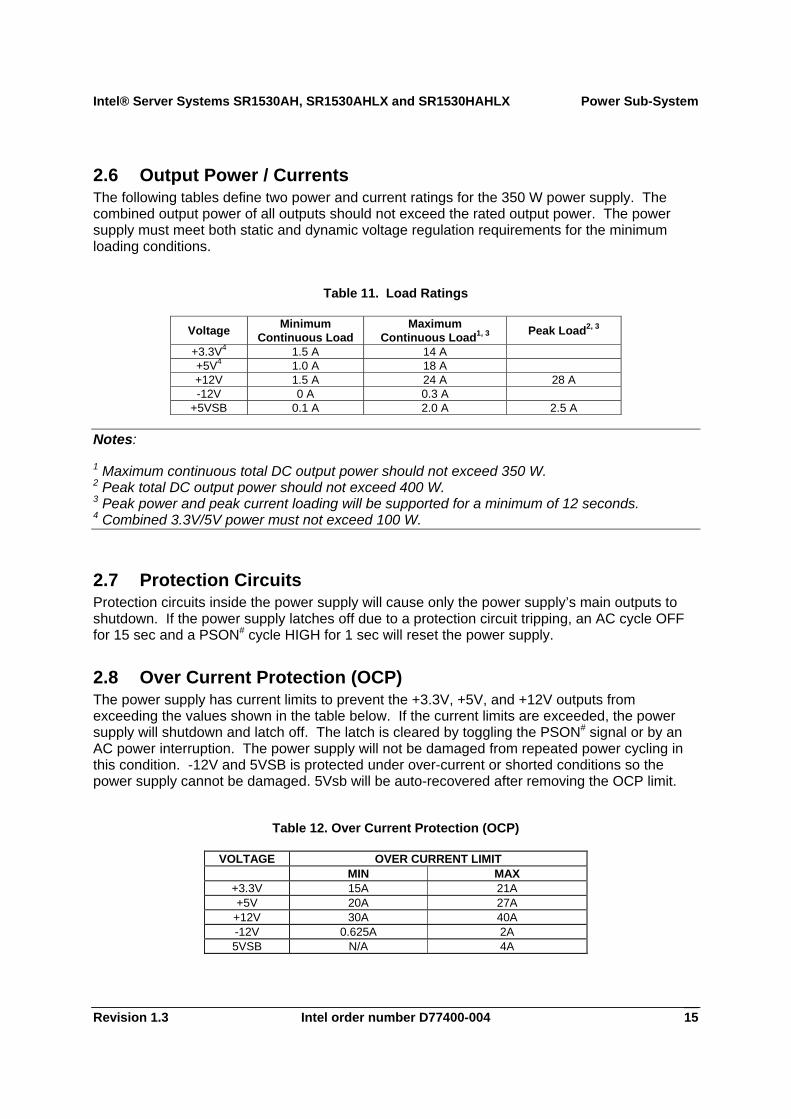
2.6 Output Power / Currents The following tables define two power and current ratings for the 350 W power supply. The combined output power of all outputs should not exceed the rated output power. The power supply must meet both static and dynamic voltage regulation requirements for the minimum loading conditions.
Table 11. Load Ratings
Voltage Minimum Continuous Load
Maximum Continuous Load1, 3 Peak Load2, 3
+3.3V4 1.5 A 14 A +5V4 1.0 A 18 A +12V 1.5 A 24 A 28 A -12V 0 A 0.3 A
+5VSB 0.1 A 2.0 A 2.5 A
Notes:
1 Maximum continuous total DC output power should not exceed 350 W. 2 Peak total DC output power should not exceed 400 W. 3 Peak power and peak current loading will be supported for a minimum of 12 seconds. 4 Combined 3.3V/5V power must not exceed 100 W.
2.7 Protection Circuits Protection circuits inside the power supply will cause only the power supply’s main outputs to shutdown. If the power supply latches off due to a protection circuit tripping, an AC cycle OFF for 15 sec and a PSON# cycle HIGH for 1 sec will reset the power supply.
2.8 Over Current Protection (OCP) The power supply has current limits to prevent the +3.3V, +5V, and +12V outputs from exceeding the values shown in the table below. If the current limits are exceeded, the power supply will shutdown and latch off. The latch is cleared by toggling the PSON# signal or by an AC power interruption. The power supply will not be damaged from repeated power cycling in this condition. -12V and 5VSB is protected under over-current or shorted conditions so the power supply cannot be damaged. 5Vsb will be auto-recovered after removing the OCP limit.
Table 12. Over Current Protection (OCP)
VOLTAGE OVER CURRENT LIMIT MIN MAX
+3.3V 15A 21A +5V 20A 27A
+12V 30A 40A -12V 0.625A 2A 5VSB N/A 4A
Power Sub-System Intel® Server Systems SR1530AH, SR1530AHLX and SR1530HAHLX
Intel order number D77400-004 Revision 1.3 16
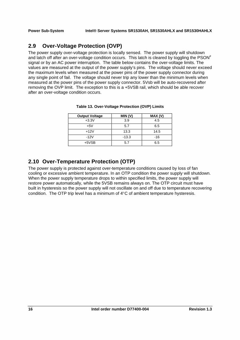
2.9 Over-Voltage Protection (OVP) The power supply over-voltage protection is locally sensed. The power supply will shutdown and latch off after an over-voltage condition occurs. This latch is cleared by toggling the PSON# signal or by an AC power interruption. The table below contains the over-voltage limits. The values are measured at the output of the power supply’s pins. The voltage should never exceed the maximum levels when measured at the power pins of the power supply connector during any single point of fail. The voltage should never trip any lower than the minimum levels when measured at the power pins of the power supply connector. 5Vsb will be auto-recovered after removing the OVP limit. The exception to this is a +5VSB rail, which should be able recover after an over-voltage condition occurs.
Table 13. Over-Voltage Protection (OVP) Limits
Output Voltage MIN (V) MAX (V) +3.3V 3.9 4.5 +5V 5.7 6.5 +12V 13.3 14.5 -12V -13.3 -16
+5VSB 5.7 6.5
2.10 Over-Temperature Protection (OTP) The power supply is protected against over-temperature conditions caused by loss of fan cooling or excessive ambient temperature. In an OTP condition the power supply will shutdown. When the power supply temperature drops to within specified limits, the power supply will restore power automatically, while the 5VSB remains always on. The OTP circuit must have built in hysteresis so the power supply will not oscillate on and off due to temperature recovering condition. The OTP trip level has a minimum of 4°C of ambient temperature hysteresis.
Intel® Server Systems SR1530AH, SR1530AHLX and SR1530HAHLX Cooling Sub-System
Revision 1.3 Intel order number D77400-004 17
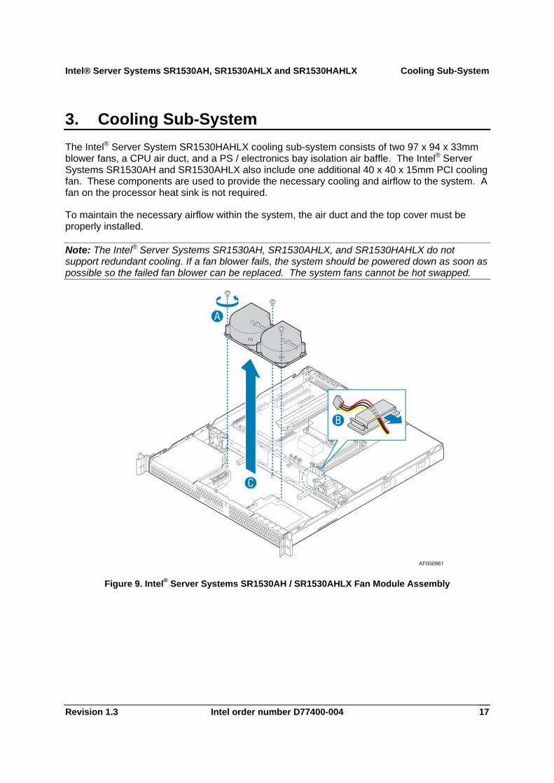
3. Cooling Sub-System The Intel® Server System SR1530HAHLX cooling sub-system consists of two 97 x 94 x 33mm blower fans, a CPU air duct, and a PS / electronics bay isolation air baffle. The Intel® Server Systems SR1530AH and SR1530AHLX also include one additional 40 x 40 x 15mm PCI cooling fan. These components are used to provide the necessary cooling and airflow to the system. A fan on the processor heat sink is not required.
To maintain the necessary airflow within the system, the air duct and the top cover must be properly installed.
Note: The Intel® Server Systems SR1530AH, SR1530AHLX, and SR1530HAHLX do not support redundant cooling. If a fan blower fails, the system should be powered down as soon as possible so the failed fan blower can be replaced. The system fans cannot be hot swapped.
Figure 9. Intel® Server Systems SR1530AH / SR1530AHLX Fan Module Assembly
Cooling Sub-System Intel® Server Systems SR1530AH, SR1530AHLX and SR1530HAHLX
Intel order number D77400-004 Revision 1.3 18
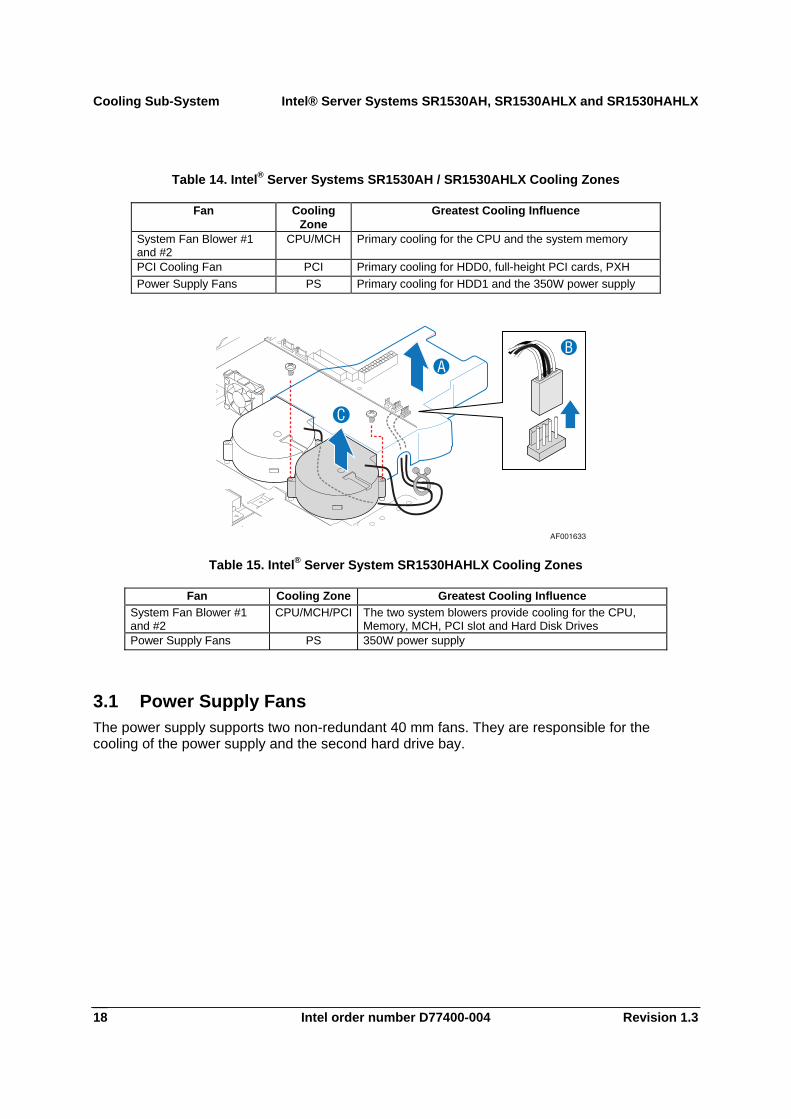
Table 14. Intel® Server Systems SR1530AH / SR1530AHLX Cooling Zones
Fan Cooling Zone
Greatest Cooling Influence
System Fan Blower #1 and #2
CPU/MCH Primary cooling for the CPU and the system memory
PCI Cooling Fan PCI Primary cooling for HDD0, full-height PCI cards, PXH Power Supply Fans PS Primary cooling for HDD1 and the 350W power supply
C
AB
AF001633
Table 15. Intel® Server System SR1530HAHLX Cooling Zones
Fan Cooling Zone Greatest Cooling Influence System Fan Blower #1 and #2
CPU/MCH/PCI The two system blowers provide cooling for the CPU, Memory, MCH, PCI slot and Hard Disk Drives
Power Supply Fans PS 350W power supply
3.1 Power Supply Fans The power supply supports two non-redundant 40 mm fans. They are responsible for the cooling of the power supply and the second hard drive bay.
Intel® Server Systems SR1530AH, SR1530AHLX and SR1530HAHLX Cooling Sub-System
Revision 1.3 Intel order number D77400-004 19
AF000665
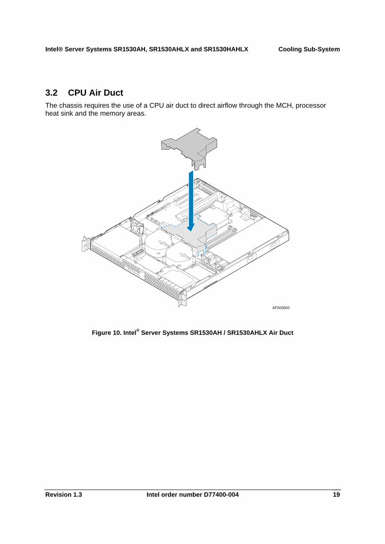
3.2 CPU Air Duct The chassis requires the use of a CPU air duct to direct airflow through the MCH, processor heat sink and the memory areas.
Figure 10. Intel® Server Systems SR1530AH / SR1530AHLX Air Duct
Cooling Sub-System Intel® Server Systems SR1530AH, SR1530AHLX and SR1530HAHLX
Intel order number D77400-004 Revision 1.3 20
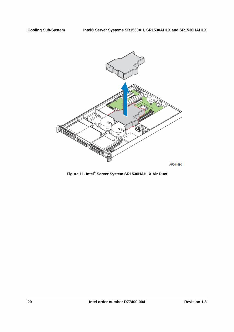
Figure 11. Intel® Server System SR1530HAHLX Air Duct
Intel® Server Systems SR1530AH, SR1530AHLX and SR1530HAHLX Drive Support
Revision 1.3 Intel order number D77400-004 21
AF001074C
AB
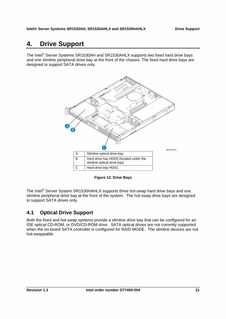
4. Drive Support The Intel® Server Systems SR1530AH and SR1530AHLX supports two fixed hard drive bays and one slimline peripheral drive bay at the front of the chassis. The fixed hard drive bays are designed to support SATA drives only.
A Slimline optical drive bay B Hard drive bay HDD0 (located under the
slimline optical drive bay) C Hard drive bay HDD1
Figure 12. Drive Bays
The Intel® Server System SR1530HAHLX supports three hot-swap hard drive bays and one slimline peripheral drive bay at the front of the system. The hot-swap drive bays are designed to support SATA drives only.
4.1 Optical Drive Support Both the fixed and hot-swap systems provide a slimline drive bay that can be configured for an IDE optical CD-ROM, or DVD/CD-ROM drive. SATA optical drives are not currently supported when the on-board SATA controller is configured for RAID MODE. The slimline devices are not hot-swappable.
Drive Support Intel® Server Systems SR1530AH, SR1530AHLX and SR1530HAHLX
Intel order number D77400-004 Revision 1.3 22
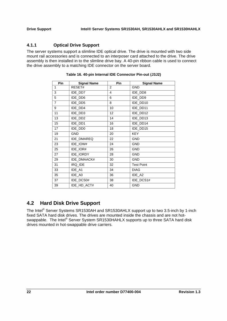
4.1.1 Optical Drive Support The server systems support a slimline IDE optical drive. The drive is mounted with two side mount rail accessories and is connected to an interposer card attached to the drive. The drive assembly is then installed in to the slimline drive bay. A 40-pin ribbon cable is used to connect the drive assembly to a matching IDE connector on the server board.
Table 16. 40-pin Internal IDE Connector Pin-out (J3J2)
Pin Signal Name Pin Signal Name 1 RESET# 2 GND 3 IDE_DD7 4 IDE_DD8 5 IDE_DD6 6 IDE_DD9 7 IDE_DD5 8 IDE_DD10 9 IDE_DD4 10 IDE_DD11 11 IDE_DD3 12 IDE_DD12 13 IDE_DD2 14 IDE_DD13 15 IDE_DD1 16 IDE_DD14 17 IDE_DD0 18 IDE_DD15 19 GND 20 KEY 21 IDE_DMAREQ 22 GND 23 IDE_IOW# 24 GND 25 IDE_IOR# 26 GND 27 IDE_IORDY 28 GND 29 IDE_DMAACK# 30 GND 31 IRQ_IDE 32 Test Point 33 IDE_A1 34 DIAG 35 IDE_A0 36 IDE_A2 37 IDE_DCS0# 38 IDE_DCS1# 39 IDE_HD_ACT# 40 GND
4.2 Hard Disk Drive Support The Intel® Server Systems SR1530AH and SR1530AHLX support up to two 3.5-inch by 1-inch fixed SATA hard disk drives. The drives are mounted inside the chassis and are not hot-swappable. The Intel® Server System SR1530HAHLX supports up to three SATA hard disk drives mounted in hot-swappable drive carriers.
Intel® Server Systems SR1530AH, SR1530AHLX and SR1530HAHLX Drive Support
Revision 1.3 Intel order number D77400-004 23
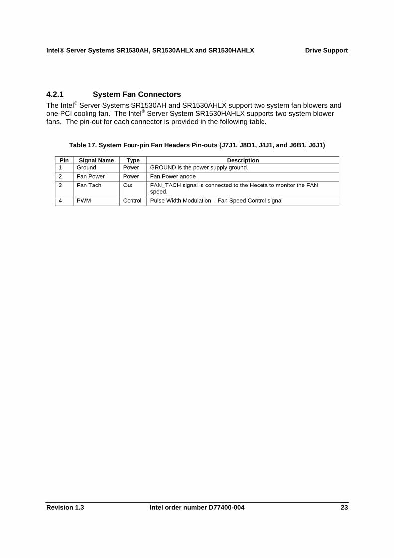
4.2.1 System Fan Connectors The Intel® Server Systems SR1530AH and SR1530AHLX support two system fan blowers and one PCI cooling fan. The Intel® Server System SR1530HAHLX supports two system blower fans. The pin-out for each connector is provided in the following table.
Table 17. System Four-pin Fan Headers Pin-outs (J7J1, J8D1, J4J1, and J6B1, J6J1)
Pin Signal Name Type Description 1 Ground Power GROUND is the power supply ground. 2 Fan Power Power Fan Power anode 3 Fan Tach Out FAN_TACH signal is connected to the Heceta to monitor the FAN
speed. 4 PWM Control Pulse Width Modulation – Fan Speed Control signal
Front Control Panel Intel® Server Systems SR1530AH, SR1530AHLX and SR1530HAHLX
Intel order number D77400-004 Revision 1.3 24
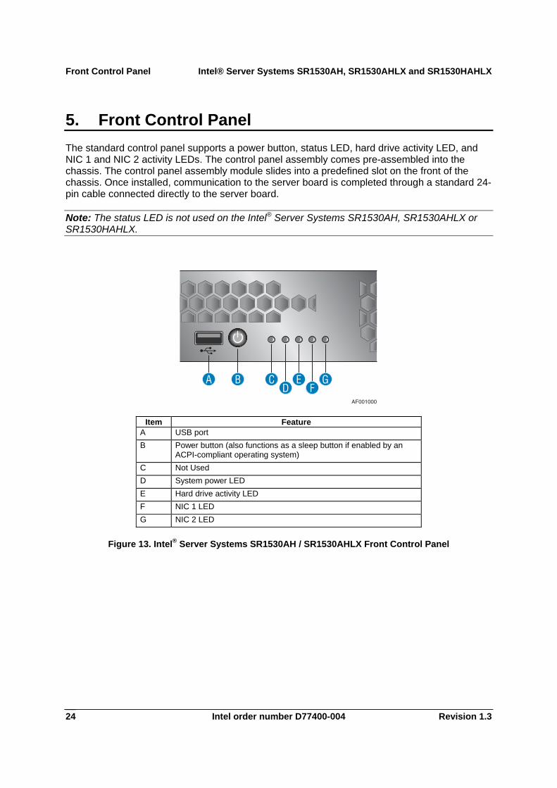
5. Front Control Panel The standard control panel supports a power button, status LED, hard drive activity LED, and NIC 1 and NIC 2 activity LEDs. The control panel assembly comes pre-assembled into the chassis. The control panel assembly module slides into a predefined slot on the front of the chassis. Once installed, communication to the server board is completed through a standard 24-pin cable connected directly to the server board.
Note: The status LED is not used on the Intel® Server Systems SR1530AH, SR1530AHLX or SR1530HAHLX.
AF001000
BAD
EF
GC
Item Feature A USB port B Power button (also functions as a sleep button if enabled by an
ACPI-compliant operating system) C Not Used D System power LED E Hard drive activity LED F NIC 1 LED G NIC 2 LED
Figure 13. Intel® Server Systems SR1530AH / SR1530AHLX Front Control Panel
Intel® Server Systems SR1530AH, SR1530AHLX and SR1530HAHLX Front Control Panel
Revision 1.3 Intel order number D77400-004 25
A C DB E
G FAF001610
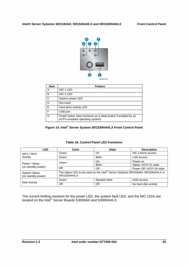
Item Feature
A NIC 1 LED B NIC 2 LED C System power LED D Not Used E Hard drive activity LED F USB port G Power button (also functions as a sleep button if enabled by an
ACPI-compliant operating system)
Figure 14. Intel® Server System SR1530HAHLX Front Control Panel
Table 18. Control Panel LED Functions
LED Color State Description Green On NIC Link/no access NIC1 / NIC2
Activity Green Blink LAN access On Power on Green Blink Sleep / ACPI S1 state Power / Sleep
(on standby power) Off Off Power Off / ACPI S4 state System Status (on standby power)
The status LED is not used on the Intel® Server Systems SR1530AH, SR1530AHLX or SR1530HAHLX. Green Random blink HDD access
Disk Activity Off Off No hard disk activity
The current limiting resistors for the power LED, the system fault LED, and the NIC LEDs are located on the Intel® Server Boards S3000AH and S3000AHLX.
Front Control Panel Intel® Server Systems SR1530AH, SR1530AHLX and SR1530HAHLX
Intel order number D77400-004 Revision 1.3 26
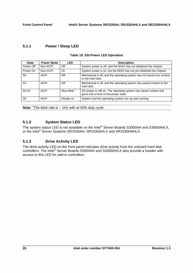
5.1.1 Power / Sleep LED
Table 19. SSI Power LED Operation
State Power Mode LED Description Power Off Non-ACPI Off System power is off, and the BIOS has not initialized the chipset. Power On Non-ACPI On System power is on, but the BIOS has not yet initialized the chipset. S5 ACPI Off Mechanical is off, and the operating system has not saved any context
to the hard disk. S4 ACPI Off Mechanical is off, and the operating system has saved context to the
hard disk. S3-S1 ACPI Slow blink 1 DC power is still on. The operating system has saved context and
gone into a level of low-power state. S0 ACPI Steady on System and the operating system are up and running.
Note: 1The blink rate is ~ 1Hz with at 50% duty cycle.
5.1.2 System Status LED The system status LED is not available on the Intel® Server Boards S3000AH and S3000AHLX, or the Intel® Server Systems SR1530AH, SR1530AHLX and SR1530HAHLX.
5.1.3 Drive Activity LED The drive activity LED on the front panel indicates drive activity from the onboard hard disk controllers. The Intel® Server Boards S3000AH and S3000AHLX also provide a header with access to this LED for add-in controllers.
Intel® Server Systems SR1530AH, SR1530AHLX and SR1530HAHLX PCI Riser Cards
Revision 1.3 Intel order number D77400-004 27
AF000676
B
A
C
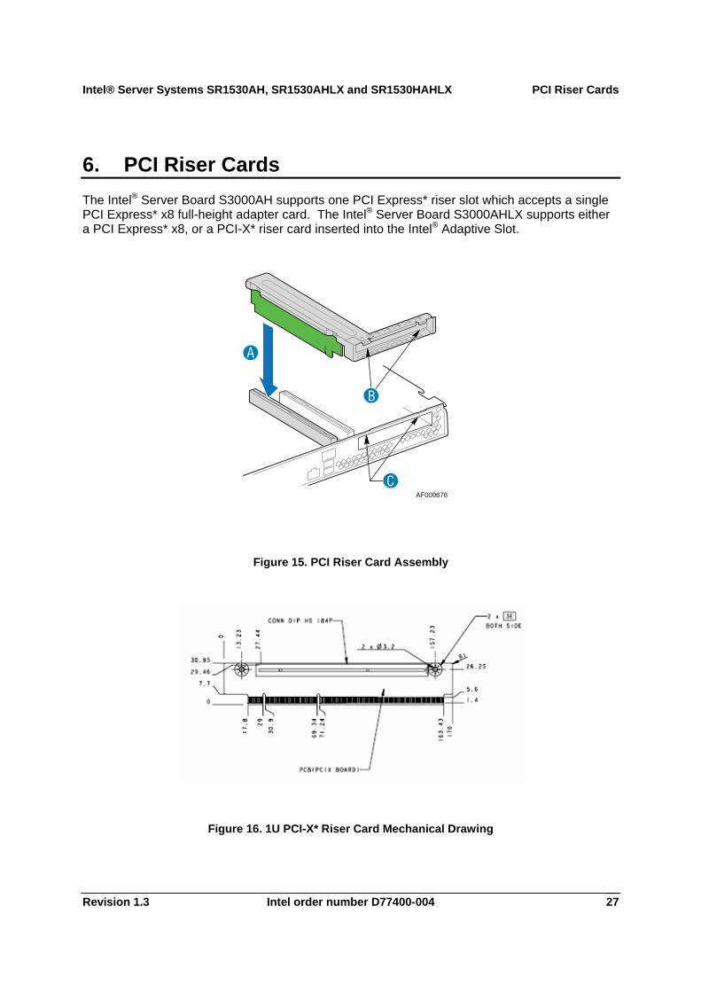
6. PCI Riser Cards The Intel® Server Board S3000AH supports one PCI Express* riser slot which accepts a single PCI Express* x8 full-height adapter card. The Intel® Server Board S3000AHLX supports either a PCI Express* x8, or a PCI-X* riser card inserted into the Intel® Adaptive Slot.
Figure 15. PCI Riser Card Assembly
Figure 16. 1U PCI-X* Riser Card Mechanical Drawing
PCI Riser Cards Intel® Server Systems SR1530AH, SR1530AHLX and SR1530HAHLX
Intel order number D77400-004 Revision 1.3 28
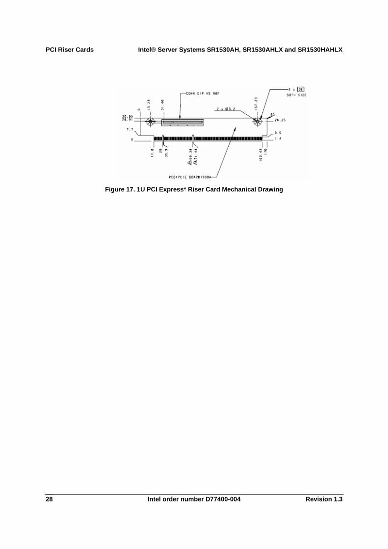
Figure 17. 1U PCI Express* Riser Card Mechanical Drawing
Intel® Server Systems SR1530AH, SR1530AHLX and SR1530HAHLX Hot-swap Backplane
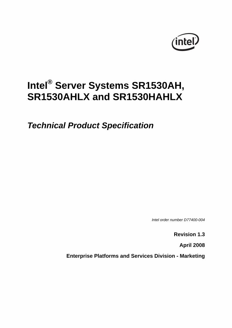
Revision 1.3 Intel order number D77400-004 29
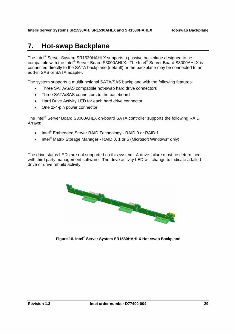
7. Hot-swap Backplane The Intel® Server System SR1530HAHLX supports a passive backplane designed to be compatible with the Intel® Server Board S3000AHLX. The Intel® Server Board S3000AHLX is connected directly to the SATA backplane (default) or the backplane may be connected to an add-in SAS or SATA adapter.
The system supports a multifunctional SATA/SAS backplane with the following features: • Three SATA/SAS compatible hot-swap hard drive connectors • Three SATA/SAS connectors to the baseboard • Hard Drive Activity LED for each hard drive connector • One 2x4-pin power connector
The Intel® Server Board S3000AHLX on-board SATA controller supports the following RAID Arrays:
• Intel® Embedded Server RAID Technology - RAID 0 or RAID 1 • Intel® Matrix Storage Manager - RAID 0, 1 or 5 (Microsoft Windows* only)
The drive status LEDs are not supported on this system. A drive failure must be determined with third party management software. The drive activity LED will change to indicate a failed drive or drive rebuild activity.
Figure 18. Intel® Server System SR1530HAHLX Hot-swap Backplane

Hot-swap Backplane Intel® Server Systems SR1530AH, SR1530AHLX and SR1530HAHLX
Intel order number D77400-004 Revision 1.3 30
Table 20. Passive SATA/SAS Backplane Power Connector Pin-out (J7)
Pin # Signal Name 1 Ground 2 Ground 3 P5V 4 P5V 5 P12V 6 P12V 7 No Connection 8 P3V3
Table 21. Passive SATA/SAS Backplane Connector to Hard Drive Pin-out (J1, J2, J3)
Pin # Signal Name S1 Ground S2 SAS_DRVxA_RX_P S3 SAS_DRVxA_RX_N S4 Ground S5 SAS_DRVxA_TX_N S6 SAS_DRVxA_TX_P S7 Ground P1 TP P2 TP P3 TP P4 Ground P5 Ground P6 Ground P7 P5V_DRVx_PRECHG P8 P5V P9 P5V P10 Ground P11 LED_DRVx_READY_N P12 Ground P13 P12V_DRVx_PRECHG P14 P12V P15 P12V
Intel® Server Systems SR1530AH, SR1530AHLX and SR1530HAHLX Hot-swap Backplane
Revision 1.3 Intel order number D77400-004 31
Table 22. Passive SATA/SAS Backplane I/O Connector to Baseboard Pin-out (J4, J5, J6)
Pin # Signal Name 1 Ground 2 SASx_EP_RX_P 3 SASX_EP_RX_N 4 Ground 5 SASx_EP_TX_N 6 SASx_EP_TX_P 7 Ground
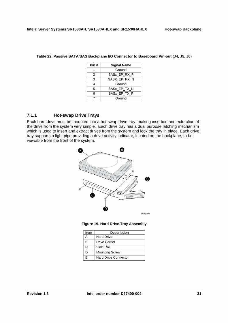
7.1.1 Hot-swap Drive Trays Each hard drive must be mounted into a hot-swap drive tray, making insertion and extraction of the drive from the system very simple. Each drive tray has a dual purpose latching mechanism which is used to insert and extract drives from the system and lock the tray in place. Each drive tray supports a light pipe providing a drive activity indicator, located on the backplane, to be viewable from the front of the system.
TP02106
A
B
D
C
E
Figure 19. Hard Drive Tray Assembly
Item Description A Hard Drive B Drive Carrier C Slide Rail D Mounting Screw E Hard Drive Connector
Supported Server Boards Intel® Server Systems SR1530AH, SR1530AHLX and SR1530HAHLX
Intel order number D77400-004 Revision 1.3 32
8. Supported Server Boards The Intel® Server Systems SR1530AH, SR1530AHLX, and SR1530HAHLX are mechanically and functionally designed to support the Intel® Server Boards S3000AH and S3000AHLX. See the Intel® Server Board S3000AH Technical Product Specification for detailed server board information.
Intel® Server Systems SR1530AH, SR1530AHLX and SR1530HAHLX Specifications
Revision 1.3 Intel order number D77400-004 33
9. Specifications
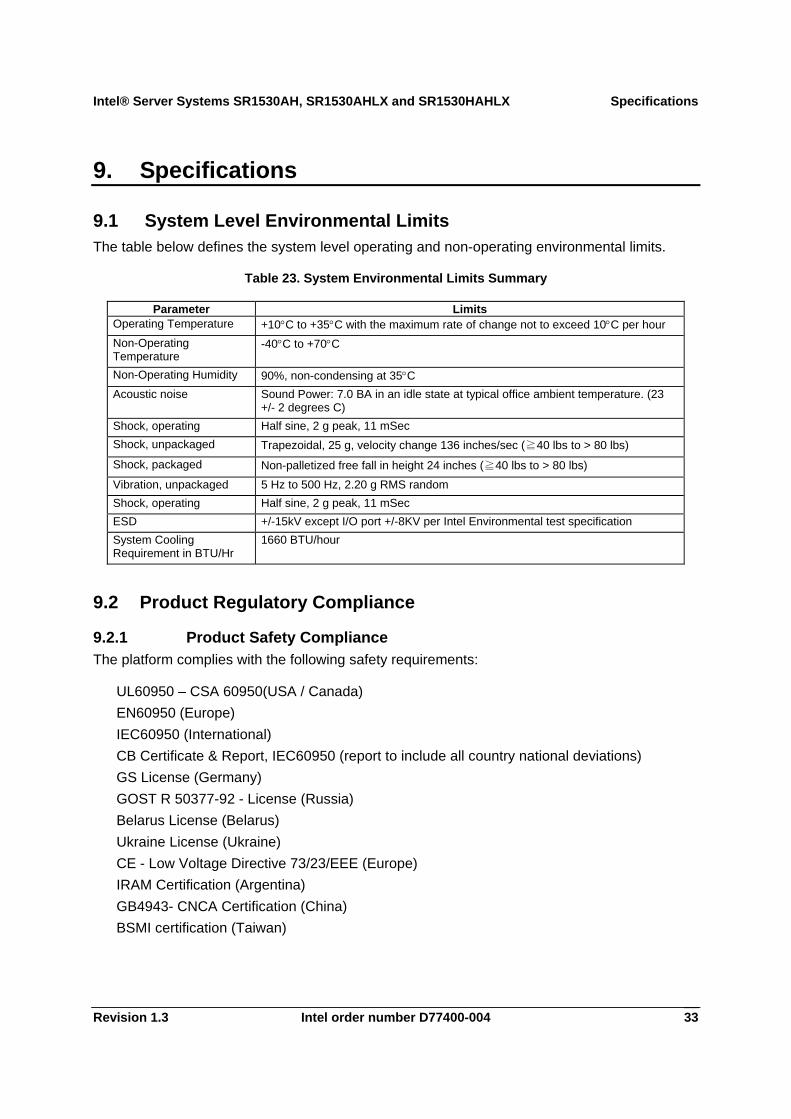
9.1 System Level Environmental Limits The table below defines the system level operating and non-operating environmental limits.
Table 23. System Environmental Limits Summary
Parameter Limits Operating Temperature +10°C to +35°C with the maximum rate of change not to exceed 10°C per hour Non-Operating Temperature
-40°C to +70°C
Non-Operating Humidity 90%, non-condensing at 35°C Acoustic noise Sound Power: 7.0 BA in an idle state at typical office ambient temperature. (23
+/- 2 degrees C) Shock, operating Half sine, 2 g peak, 11 mSec Shock, unpackaged Trapezoidal, 25 g, velocity change 136 inches/sec (≧40 lbs to > 80 lbs) Shock, packaged Non-palletized free fall in height 24 inches (≧40 lbs to > 80 lbs) Vibration, unpackaged 5 Hz to 500 Hz, 2.20 g RMS random Shock, operating Half sine, 2 g peak, 11 mSec ESD +/-15kV except I/O port +/-8KV per Intel Environmental test specification System Cooling Requirement in BTU/Hr
1660 BTU/hour
9.2 Product Regulatory Compliance
9.2.1 Product Safety Compliance The platform complies with the following safety requirements:
UL60950 – CSA 60950(USA / Canada) EN60950 (Europe) IEC60950 (International) CB Certificate & Report, IEC60950 (report to include all country national deviations) GS License (Germany) GOST R 50377-92 - License (Russia) Belarus License (Belarus) Ukraine License (Ukraine) CE - Low Voltage Directive 73/23/EEE (Europe) IRAM Certification (Argentina) GB4943- CNCA Certification (China) BSMI certification (Taiwan)
Specifications Intel® Server Systems SR1530AH, SR1530AHLX and SR1530HAHLX
Intel order number D77400-004 Revision 1.3 34
9.2.2 Product EMC Compliance The platform has been tested and verified to comply with the following electromagnetic compatibility (EMC) regulations when installed a compatible Intel host system. For information on compatible host system(s) refer to the Intel Server Builder Web site or contact your local Intel representative.
FCC (Class A Verification) – Radiated & Conducted Emissions (USA) CISPR 22 – Emissions (International) EN55022 - Emissions (Europe) EN55024 - Immunity (Europe) EN61000-3-2 - Harmonics (Europe) EN61000-3-3 - Voltage Flicker (Europe) CE – EMC Directive 89/336/EEC (Europe) VCCI Emissions (Japan) AS/NZS 3548 Emissions (Australia / New Zealand) BSMI CNS13438 Emissions (Taiwan) GOST R 29216-91 Emissions (Russia) GOST R 50628-95 Immunity (Russia) Belarus License (Belarus) Ukraine License (Ukraine) RRL MIC Notice No. 1997-41 (EMC) & 1997-42 (EMI) (Korea) GB 9254 - CNCA Certification (China) GB 17625 - (Harmonics) CNCA Certification (China)
9.2.3 Certifications / Registrations / Declarations UL Certification (US/Canada) CB Certification (International) CE Declaration of Conformity (CENELEC Europe) GS Certification (Germany) FCC/ICES-003 Class A Attestation (USA/Canada) VCCI Certification (Japan) C-Tick Declaration of Conformity (Australia) MED Declaration of Conformity (New Zealand) BSMI Certification (Taiwan) GOST R Certification / License (Russia) Belarus Certification / License (Belarus) Ukraine Certification (Ukraine) RRL Certification (Korea) IRAM Certification (Argentina) CNCA Certification (China)
Intel® Server Systems SR1530AH, SR1530AHLX and SR1530HAHLX Specifications
Revision 1.3 Intel order number D77400-004 35
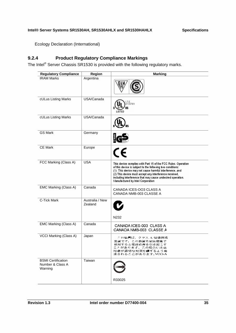
Ecology Declaration (International)
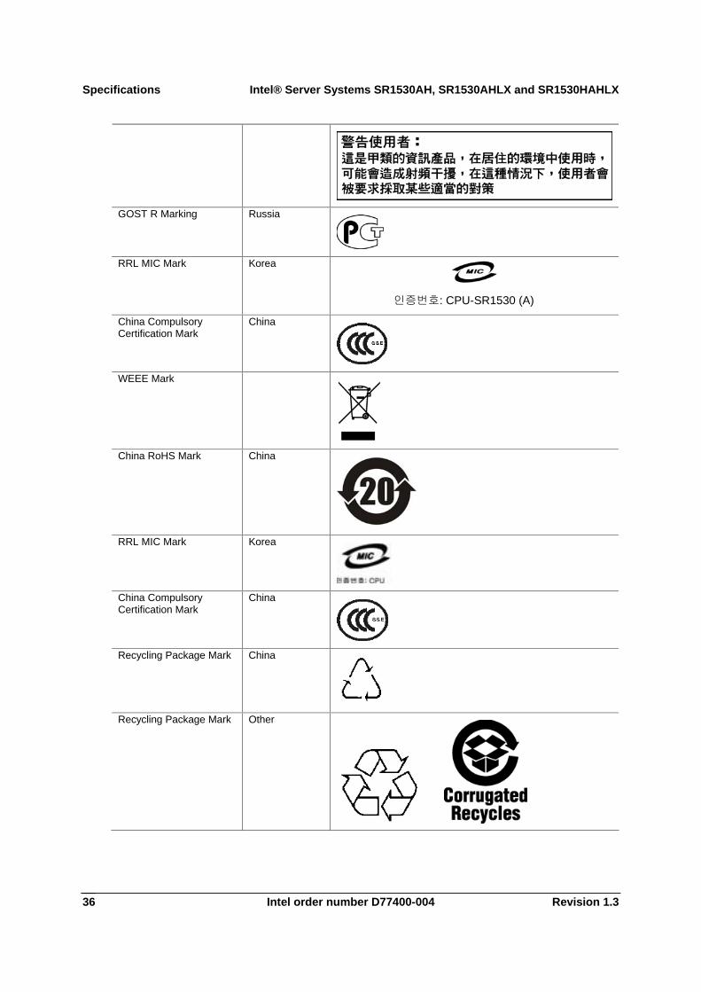
9.2.4 Product Regulatory Compliance Markings The Intel® Server Chassis SR1530 is provided with the following regulatory marks.
Regulatory Compliance Region Marking IRAM Marks Argentina
cULus Listing Marks USA/Canada
cULus Listing Marks USA/Canada
GS Mark Germany
CE Mark Europe
FCC Marking (Class A) USA
EMC Marking (Class A) Canada CANADA ICES-OO3 CLASS A CANADA NMB-003 CLASSE A
C-Tick Mark Australia / New Zealand
N232
EMC Marking (Class A) Canada
VCCI Marking (Class A) Japan
BSMI Certification Number & Class A Warning
Taiwan
R33025
Specifications Intel® Server Systems SR1530AH, SR1530AHLX and SR1530HAHLX
Intel order number D77400-004 Revision 1.3 36
GOST R Marking Russia
RRL MIC Mark Korea
인증번호: CPU-SR1530 (A)
China Compulsory Certification Mark
China
WEEE Mark
China RoHS Mark China
RRL MIC Mark Korea
China Compulsory Certification Mark
China
Recycling Package Mark China
Recycling Package Mark Other

Intel® Server Systems SR1530AH, SR1530AHLX and SR1530HAHLX Specifications
Revision 1.3 Intel order number D77400-004 37
9.3 Electromagnetic Compatibility Notices
9.3.1 USA This device complies with Part 15 of the FCC Rules. Operation is subject to the following two conditions: (1) this device may not cause harmful interference, and (2) this device must accept any interference received, including interference that may cause undesired operation.
For questions related to the EMC performance of this product, contact:
Intel Corporation 5200 N.E. Elam Young Parkway Hillsboro, OR 97124 1-800-628-8686 This equipment has been tested and found to comply with the limits for a Class A digital device, pursuant to Part 15 of the FCC Rules. These limits are designed to provide reasonable protection against harmful interference in a residential installation. This equipment generates, uses, and can radiate radio frequency energy and, if not installed and used in accordance with the instructions, may cause harmful interference to radio communications. However, there is no guarantee that interference will not occur in a particular installation. If this equipment does cause harmful interference to radio or television reception, which can be determined by turning the equipment off and on, the user is encouraged to try to correct the interference by one or more of the following measures:
Reorient or relocate the receiving antenna. Increase the separation between the equipment and the receiver. Connect the equipment to an outlet on a circuit other than the one to which the receiver is
connected. Consult the dealer or an experienced radio/TV technician for help.
Any changes or modifications not expressly approved by the grantee of this device could void the user’s authority to operate the equipment. The customer is responsible for ensuring compliance of the modified product.
Only peripherals (computer input/output devices, terminals, printers, etc.) that comply with FCC Class B limits may be attached to this computer product. Operation with noncompliant peripherals is likely to result in interference to radio and TV reception.
All cables used to connect to peripherals must be shielded and grounded. Operation with cables, connected to peripherals that are not shielded and grounded may result in interference to radio and TV reception.
9.3.2 FCC Verification Statement Product Type: SR1530; S3000AH; S3000AHLX
This device complies with Part 15 of the FCC Rules. Operation is subject to the following two conditions: (1) This device may not cause harmful interference, and (2) this device must accept any interference received, including interference that may cause undesired operation.

Specifications Intel® Server Systems SR1530AH, SR1530AHLX and SR1530HAHLX
Intel order number D77400-004 Revision 1.3 38
For questions related to the EMC performance of this product, contact:
Intel Corporation 5200 N.E. Elam Young Parkway Hillsboro, OR 97124-6497
Phone: 1 (800)-INTEL4U or 1 (800) 628-8686
9.3.3 ICES-003 (Canada) Cet appareil numérique respecte les limites bruits radioélectriques applicables aux appareils numériques de Classe A prescrites dans la norme sur le matériel brouilleur: “Appareils Numériques”, NMB-003 édictée par le Ministre Canadian des Communications.
(English translation of the notice above) This digital apparatus does not exceed the Class A limits for radio noise emissions from digital apparatus set out in the interference-causing equipment standard entitled “Digital Apparatus,” ICES-003 of the Canadian Department of Communications.
9.3.4 Europe (CE Declaration of Conformity) This product has been tested in accordance too, and complies with the Low Voltage Directive (73/23/EEC) and EMC Directive (89/336/EEC). The product has been marked with the CE Mark to illustrate its compliance.
9.3.5 Japan EMC Compatibility Electromagnetic Compatibility Notices (International)
English translation of the notice above:
This is a Class A product based on the standard of the Voluntary Control Council For Interference (VCCI) from Information Technology Equipment. If this is used near a radio or television receiver in a domestic environment, it may cause radio interference. Install and use the equipment according to the instruction manual.
9.3.6 BSMI (Taiwan) The BSMI Certification number and the following warning is located on the product safety label which is located on the bottom side (pedestal orientation) or side (rack mount configuration).
Intel® Server Systems SR1530AH, SR1530AHLX and SR1530HAHLX Specifications
Revision 1.3 Intel order number D77400-004 39
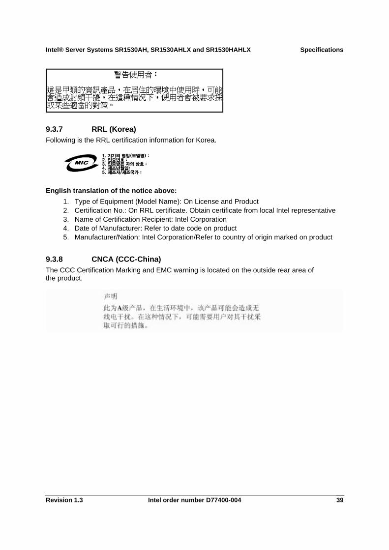
9.3.7 RRL (Korea) Following is the RRL certification information for Korea.
English translation of the notice above: 1. Type of Equipment (Model Name): On License and Product 2. Certification No.: On RRL certificate. Obtain certificate from local Intel representative 3. Name of Certification Recipient: Intel Corporation 4. Date of Manufacturer: Refer to date code on product 5. Manufacturer/Nation: Intel Corporation/Refer to country of origin marked on product
9.3.8 CNCA (CCC-China) The CCC Certification Marking and EMC warning is located on the outside rear area of the product.
Specifications Intel® Server Systems SR1530AH, SR1530AHLX and SR1530HAHLX
Intel order number D77400-004 Revision 1.3 40
9.4 Replacing the Back up Battery The lithium battery on the server board powers the real time clock (RTC) for up to 10 years in the absence of power. When the battery starts to weaken, it loses voltage, and the server settings stored in CMOS RAM in the RTC (for example, the date and time) may be wrong. Contact your customer service representative or dealer for a list of approved devices.
WARNING
Danger of explosion if battery is incorrectly replaced. Replace only with the same or equivalent type recommended by the equipment manufacturer. Discard used batteries according to manufacturer’s instructions.
ADVARSEL!
Lithiumbatteri - Eksplosionsfare ved fejlagtig håndtering. Udskiftning må kun ske med batteri af samme fabrikat og type. Levér det brugte batteri tilbage til leverandøren.
ADVARSEL
Lithiumbatteri - Eksplosjonsfare. Ved utskifting benyttes kun batteri som anbefalt av apparatfabrikanten. Brukt batteri returneres apparatleverandøren.
VARNING
Explosionsfara vid felaktigt batteribyte. Använd samma batterityp eller en ekvivalent typ som rekommenderas av apparattillverkaren. Kassera använt batteri enligt fabrikantens instruktion.
VAROITUS
Paristo voi räjähtää, jos se on virheellisesti asennettu. Vaihda paristo ainoastaan laitevalmistajan suosittelemaan tyyppiin. Hävitä käytetty paristo valmistajan ohjeiden mukaisesti.

Intel® Server Systems SR1530AH, SR1530AHLX and SR1530HAHLX Specifications
Revision 1.3 Intel order number D77400-004 41
9.5 Serviceability and Availability The system is designed to be serviced by qualified technical personnel only.
The desired Mean Time to Repair (MTTR) of the system is 30 minutes including diagnosis of the system problem. To meet this goal, the system enclosure and hardware have been designed to minimize the MTTR.
Following are the maximum times that a trained field service technician should take to perform the listed system maintenance procedures, after diagnosis of the system and identifying the failed component.
Activity Time Estimate Remove cover 1 min Remove and replace hard disk drive 5 min Remove and replace power supply module 1 min Remove and replace system fan 7 min Remove and replace control panel module 2 min Remove and replace baseboard 15 min
9.5.1 Product Ecology Requirements
Intel has a system in place to restrict the use of banned substances in accordance with world wide product ecology regulatory requirements. Suppliers Declarations of Conformity to the banned substances must be obtained from all suppliers; and a Material Declaration Data Sheet (MDDS) must be produced to illustrate compliance. Due verification of random materials is required as a screening / audit to verify suppliers declarations.
Item Requirement Description P R Y/N/D Src
Product Ecology All materials, parts and subassemblies must not contain restricted materials as defined in Intel’s Environmental Product Content Specification of Suppliers and Outsourced Manufacturers – http://supplier.intel.com/ehs/environmental.htm
1 1 Y
Product Ecology Europe - European Directive 2002/95/EC - Restriction of Hazardous Substances (RoHS) Threshold limits and banned substances are noted below. Quantity limit of 0.1% by mass (1000 PPM) for: Lead, Mercury, Hexavalent Chromium, Polybrominated Biphenyls Diphenyl Ethers (PBB/PBDE) Quantity limit of 0.01% by mass (100 PPM) for: Cadmium
1 1 Y
Product Ecology China RoHS 1 1 Y
Specifications Intel® Server Systems SR1530AH, SR1530AHLX and SR1530HAHLX
Intel order number D77400-004 Revision 1.3 42
Product Ecology WEEE Directive 1 1 Y
Product Ecology All plastic parts that weigh >25gm shall be marked with the ISO11469 requirements for recycling. Example >PC/ABS< 1 1 Y
Product Ecology EU Packaging Directive 1 1 Y
9.6 Restriction of Hazardous Substances (RoHS) Compliance Intel has a system in place to restrict the use of banned substances in accordance with the European Directive 2002/95/EC. Compliance is based on declaration that materials banned in the RoHS Directive are either (1) below all applicable substance threshold limits or (2) an approved/pending RoHS exemption applies.
Note: RoHS implementing details are not fully defined and may change.
Threshold limits and banned substances are noted below.
Quantity limit of 0.1% by mass (1000 PPM) for: Lead Mercury Hexavalent Chromium Polybrominated Biphenyls Diphenyl Ethers (PBDE)
Quantity limit of 0.01% by mass (100 PPM) for: Cadmium
Intel® Server Systems SR1530AH, SR1530AHLX and SR1530HAHLX Specifications
Revision 1.3 Intel order number D77400-004 43
9.7 Regulated Specified Components To maintain the UL listing and compliance to other regulatory certifications and/or declarations, the following regulated components must be used and conditions adhered to. Interchanging or use of other component will void the UL listing and other product certifications and approvals.
Please contact your local Intel representative and reference documents.
• Server chassis (base chassis is provided with power supply and fans) ⎯UL listed. • Server board⎯ must use an Intel server board—UL recognized. • Add-in boards⎯must have a printed wiring board flammability rating of minimum
UL94V-1. Add-in boards containing external power connectors and/or lithium batteries must be UL recognized or UL listed. Any add-in board containing modem telecommunication circuitry must be UL listed. In addition, the modem must have the appropriate telecommunications, safety, and EMC approvals for the region in which it is sold.
• Peripheral storage devices⎯must be UL recognized or UL listed accessory and TUV or VDE licensed. Maximum power rating of any one device is 19 watts. Total server configuration is not to exceed the maximum loading conditions of the power supply
9.8 Environmental altitude operation specification The SR1530AH/SR1530HAHLX has been thermally tested at 900 meters, so the thermal performance is not adequate over 900 meters.
Specifications Intel® Server Systems SR1530AH, SR1530AHLX and SR1530HAHLX
Intel order number D77400-004 Revision 1.3 44
This page intentionally left blank
Intel® Server Systems SR1530AH, SR1530AHLX and SR1530HAHLX Appendix A: Integration Tips
Revision 1.3 Intel order number D77400-004 I
Appendix A: Integration Tips This section provides a list of useful information that is unique to the Intel® Server Chassis SR1530 and should be kept in mind while integrating and configuring your Intel® Server Board S3000AH or S3000AHLX.
• Only low-profile (1.2 inch or 30.48 mm) DIMMs can be used in the server chassis. • Processor fans are not needed and are not supported. The system fan module and
power supply fans provide the necessary system cooling. Using a processor fan in this chassis may cause Intel® System Management Software to incorrectly monitor the system fans.
• The air duct must be used to maintain system thermals. • System fans are not hot-swappable. • A screw on the front edge of the top cover is required when the unit is installed in a user-
accessible environment. • Make sure the latest system software and BIOS are installed. The latest updates can be
downloaded from http://support.intel.com/support/motherboards/server/S3000AH/.
Appendix B: POST Code DiagnosticIntel® Server Systems SR1530AH, SR1530AHLX and SR1530HAHLX
Intel order number D77400-004 Revision 1.3 II
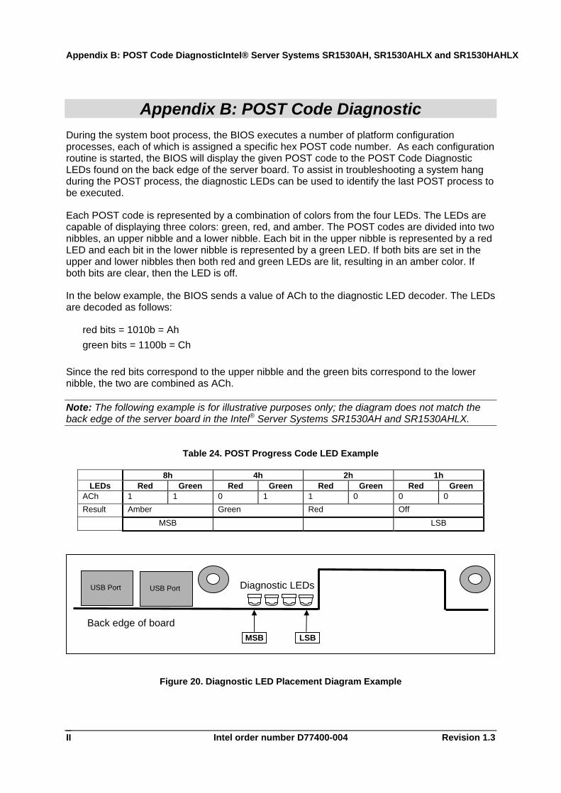
Appendix B: POST Code Diagnostic During the system boot process, the BIOS executes a number of platform configuration processes, each of which is assigned a specific hex POST code number. As each configuration routine is started, the BIOS will display the given POST code to the POST Code Diagnostic LEDs found on the back edge of the server board. To assist in troubleshooting a system hang during the POST process, the diagnostic LEDs can be used to identify the last POST process to be executed.
Each POST code is represented by a combination of colors from the four LEDs. The LEDs are capable of displaying three colors: green, red, and amber. The POST codes are divided into two nibbles, an upper nibble and a lower nibble. Each bit in the upper nibble is represented by a red LED and each bit in the lower nibble is represented by a green LED. If both bits are set in the upper and lower nibbles then both red and green LEDs are lit, resulting in an amber color. If both bits are clear, then the LED is off.
In the below example, the BIOS sends a value of ACh to the diagnostic LED decoder. The LEDs are decoded as follows:
red bits = 1010b = Ah green bits = 1100b = Ch
Since the red bits correspond to the upper nibble and the green bits correspond to the lower nibble, the two are combined as ACh.
Note: The following example is for illustrative purposes only; the diagram does not match the back edge of the server board in the Intel® Server Systems SR1530AH and SR1530AHLX.
Table 24. POST Progress Code LED Example
8h 4h 2h 1h LEDs Red Green Red Green Red Green Red Green
ACh 1 1 0 1 1 0 0 0 Result Amber Green Red Off
MSB LSB
Figure 20. Diagnostic LED Placement Diagram Example
LSBMSB
Diagnostic LEDs
Back edge of board
USB Port USB Port
Intel® Server Systems SR1530AH, SR1530AHLX and SR1530HAHLX Appendix B: POST Code Diagnostic
Revision 1.3 Intel order number D77400-004 III
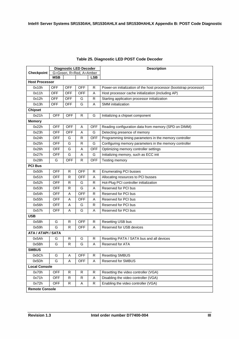
Table 25. Diagnostic LED POST Code Decoder
Diagnostic LED Decoder G=Green, R=Red, A=Amber Checkpoint MSB LSB
Description
Host Processor 0x10h OFF OFF OFF R Power-on initialization of the host processor (bootstrap processor) 0x11h OFF OFF OFF A Host processor cache initialization (including AP) 0x12h OFF OFF G R Starting application processor initialization 0x13h OFF OFF G A SMM initialization
Chipset 0x21h OFF OFF R G Initializing a chipset component
Memory 0x22h OFF OFF A OFF Reading configuration data from memory (SPD on DIMM) 0x23h OFF OFF A G Detecting presence of memory 0x24h OFF G R OFF Programming timing parameters in the memory controller 0x25h OFF G R G Configuring memory parameters in the memory controller 0x26h OFF G A OFF Optimizing memory controller settings 0x27h OFF G A G Initializing memory, such as ECC init 0x28h G OFF R OFF Testing memory
PCI Bus 0x50h OFF R OFF R Enumerating PCI busses 0x51h OFF R OFF A Allocating resources to PCI busses 0x52h OFF R G R Hot-Plug PCI controller initialization 0x53h OFF R G A Reserved for PCI bus 0x54h OFF A OFF R Reserved for PCI bus 0x55h OFF A OFF A Reserved for PCI bus 0x56h OFF A G R Reserved for PCI bus 0x57h OFF A G A Reserved for PCI bus
USB 0x58h G R OFF R Resetting USB bus 0x59h G R OFF A Reserved for USB devices
ATA / ATAPI / SATA 0x5Ah G R G R Resetting PATA / SATA bus and all devices 0x5Bh G R G A Reserved for ATA
SMBUS 0x5Ch G A OFF R Resetting SMBUS 0x5Dh G A OFF A Reserved for SMBUS
Local Console 0x70h OFF R R R Resetting the video controller (VGA) 0x71h OFF R R A Disabling the video controller (VGA) 0x72h OFF R A R Enabling the video controller (VGA)
Remote Console

Appendix B: POST Code DiagnosticIntel® Server Systems SR1530AH, SR1530AHLX and SR1530HAHLX
Intel order number D77400-004 Revision 1.3 IV
Diagnostic LED Decoder G=Green, R=Red, A=Amber Checkpoint MSB LSB
Description
0x78h G R R R Resetting the console controller 0x79h G R R A Disabling the console controller 0x7Ah G R A R Enabling the console controller
Keyboard (PS/2 or USB) 0x90h R OFF OFF R Resetting the keyboard 0x91h R OFF OFF A Disabling the keyboard 0x92h R OFF G R Detecting the presence of the keyboard 0x93h R OFF G A Enabling the keyboard 0x94h R G OFF R Clearing keyboard input buffer 0x95h R G OFF A Instructing keyboard controller to run Self Test (PS/2 only)
Mouse (PS/2 or USB) 0x98h A OFF OFF R Resetting the mouse 0x99h A OFF OFF A Detecting the mouse 0x9Ah A OFF G R Detecting the presence of mouse 0x9Bh A OFF G A Enabling the mouse
Fixed Media 0xB0h R OFF R R Resetting fixed media device 0xB1h R OFF R A Disabling fixed media device 0xB2h R OFF A R Detecting presence of a fixed media device (IDE hard drive detection,
etc.) 0xB3h R OFF A A Enabling / configuring a fixed media device
Removable Media 0xB8h A OFF R R Resetting removable media device 0xB9h A OFF R A Disabling removable media device 0xBAh A OFF A R Detecting presence of a removable media device (IDE CDROM
detection, etc.) 0xBCh A G R R Enabling / configuring a removable media device
Boot Device Selection 0xD0 R R OFF R Trying boot device selection 0xD1 R R OFF A Trying boot device selection 0xD2 R R G R Trying boot device selection 0xD3 R R G A Trying boot device selection 0xD4 R A OFF R Trying boot device selection 0xD5 R A OFF A Trying boot device selection 0xD6 R A G R Trying boot device selection 0xD7 R A G A Trying boot device selection 0xD8 A R OFF R Trying boot device selection 0xD9 A R OFF A Trying boot device selection 0XDA A R G R Trying boot device selection 0xDB A R G A Trying boot device selection 0xDC A A OFF R Trying boot device selection 0xDE A A G R Trying boot device selection 0xDF A A G A Trying boot device selection
Intel® Server Systems SR1530AH, SR1530AHLX and SR1530HAHLX Appendix B: POST Code Diagnostic
Revision 1.3 Intel order number D77400-004 V
Diagnostic LED Decoder G=Green, R=Red, A=Amber Checkpoint MSB LSB
Description
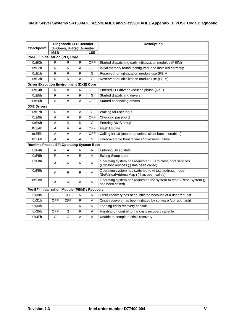
Pre-EFI Initialization (PEI) Core 0xE0h R R R OFF Started dispatching early initialization modules (PEIM) 0xE2h R R A OFF Initial memory found, configured, and installed correctly 0xE1h R R R G Reserved for initialization module use (PEIM) 0xE3h R R A G Reserved for initialization module use (PEIM)
Driver Execution Environment (DXE) Core 0xE4h R A R OFF Entered EFI driver execution phase (DXE) 0xE5h R A R G Started dispatching drivers 0xE6h R A A OFF Started connecting drivers
DXE Drivers 0xE7h R A A G Waiting for user input 0xE8h A R R OFF Checking password 0xE9h A R R G Entering BIOS setup 0xEAh A R A OFF Flash Update 0xEEh A A A OFF Calling Int 19 (one beep unless silent boot is enabled) 0xEFh A A A G Unrecoverable boot failure / S3 resume failure
Runtime Phase / EFI Operating System Boot 0xF4h R A R R Entering Sleep state 0xF5h R A R A Exiting Sleep state 0xF8h A R R R Operating system has requested EFI to close boot services
(ExitBootServices ( ) has been called) 0xF9h A R R A Operating system has switched to virtual address mode
(SetVirtualAddressMap ( ) has been called) 0xFAh A R A R Operating system has requested the system to reset (ResetSystem ()
has been called) Pre-EFI Initialization Module (PEIM) / Recovery
0x30h OFF OFF R R Crisis recovery has been initiated because of a user request 0x31h OFF OFF R A Crisis recovery has been initiated by software (corrupt flash) 0x34h OFF G R R Loading crisis recovery capsule 0x35h OFF G R A Handing off control to the crisis recovery capsule 0x3Fh G G A A Unable to complete crisis recovery

Appendix C: POST Error Beep CodesIntel® Server Systems SR1530AH, SR1530AHLX and SR1530HAHLX
Intel order number D77400-004 Revision 1.3 VI
Appendix C: POST Error Beep Codes The following table lists POST error beep codes. Prior to system video initialization, BIOS uses these beep codes to inform users of error conditions. The beep code is followed by a user visible code on POST Progress LEDs.
Table 26. POST Error Beep Codes
Beeps Error Message Description 3 Memory error System halted because a fatal error related to the memory
was detected.
Intel® Server Systems SR1530AH, SR1530AHLX and SR1530HAHLX Glossary
Revision 1.3 Intel order number D77400-004 VII
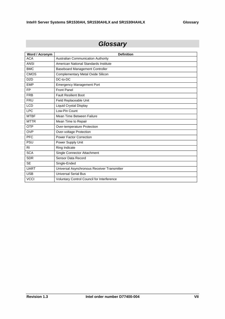
Glossary Word / Acronym Definition ACA Australian Communication Authority ANSI American National Standards Institute BMC Baseboard Management Controller CMOS Complementary Metal Oxide Silicon D2D DC-to-DC EMP Emergency Management Port FP Front Panel FRB Fault Resilient Boot FRU Field Replaceable Unit LCD Liquid Crystal Display LPC Low-Pin Count MTBF Mean Time Between Failure MTTR Mean Time to Repair OTP Over-temperature Protection OVP Over-voltage Protection PFC Power Factor Correction PSU Power Supply Unit RI Ring Indicate SCA Single Connector Attachment SDR Sensor Data Record SE Single-Ended UART Universal Asynchronous Receiver Transmitter USB Universal Serial Bus VCCI Voluntary Control Council for Interference
Reference Documents Intel® Server Systems SR1530AH, SR1530AHLX and SR1530HAHLX
Intel order number D77400-004 Revision 1.3 VIII
Reference Documents See the following documents for additional information:
• Intel® Server Board S3000AH Technical Product Specification • Intel® 3000 Series Chipsets Server Board Family Datasheet • Intel® Server Chassis SR1530 AC Power Supply Module Specification • Intel® Server Board S3000AH/S3000AHLX Tested Hardware and OS List • Intel® Server Board S3000AH/S3000AHLX / Intel® Server System
SR1530AH/SR1530AHLX Spares/Parts List and Configuration Guide