Embed Size (px)
Citation preview


TECHNICAL PROPOSAL100KWP GRID CONNECTED SOLAR PV SYSTEM


PAGE 5 / 20
TABLE OF CONTENT
TECHNICAL PROPOSAL
SYSTEM DESIGN 6
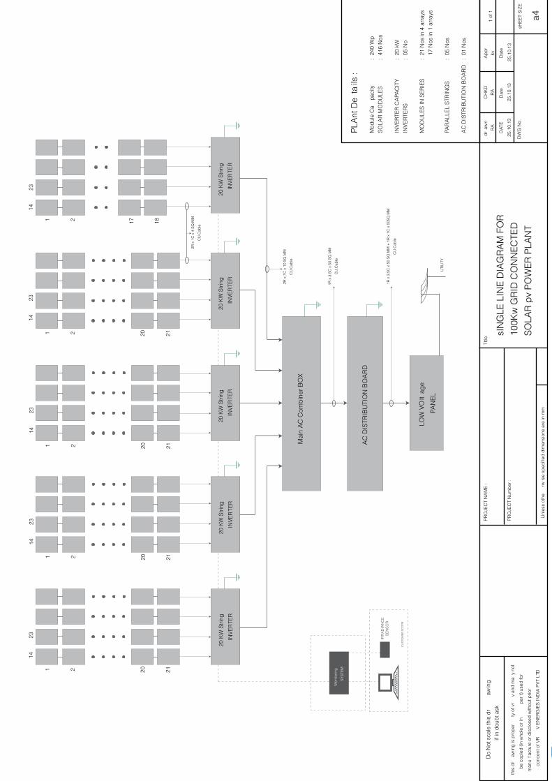
SYSTEM DESCRIPTION 9 SINGlE lINE DIaGRaM 10
SYSTEM CONFIGURaTION 11
BIll OF MaTERIal 15

PAGE 6 / 20
i. CUSTOMER REQUIREMENT
The Customer would like to install 100 kWp Grid connected Solar PV Power Plant in region of Thiruchengode, Morur, Tamil Nadu, India.
ii. DESIGN aSSUMPTIONS
Module Facing : True South
Module Tilt angle : 11°
Type of System : Grid Connected System
iii.PROPOSED TECHNOlOGY
The on-grid solar photovoltaic power plant to be proposed shall be consisting of crystalline solar modules with fixed tilt angle mounting systems and the solar inverters shall be of grid interactive type.
iv.BENEFITS OF PROPOSED TECHNOlOGY
The benefit of crystalline technology as compared to other existing technologies is as follows;
It occupies less area when compared to other thin film technologies
Proven technology over years
abundant semiconductor materials to support high volume production and demand.
High volumes of production facilities throughout world
v. ENERGY SIMUlaTION RESUlT
Based on the above inputs & assumption, an energy simulation of solar radiation available at the geographical location for solar modules has been derived from NaSa Surface meteorology and solar energy.
1. SYSTEM DESIGN

PAGE 7 / 20
aSSUMPTIONS THaT aRE CONSIDERED FOR CalCUlaTING THE ENERGY YIElD aRE lISTED BElOW
Site : Sri Shanmuga college of Engineering & Technology Thiruchengode, Morur, Tamil Nadu, India.

PAGE 8 / 20
VI.DESIGN SUMMaRY
Total Installed capacity : 99.840Kwp
PV Module : 240Wp Crystalline Modules (Kl240)
Total Number of Modules : 416 Numbers
GRID TIE Inverter : 100 kW
Total Number of Inverters : 1No.
approx yearly generation/KWp : 1642.5 kwh/kwp/year**
approx Yearly generation : 164.25 MWh/annum**
** approx average Daily generation : 425 - 475 kwh**
Module Tilt angle : 11Deg
Module orientation : True South
area required for module installation : 900 Sq.mtrs.
** Note
The above values are indicative for the location based on the historical radiation data. The actual data may vary depending on the site conditions.

PAGE 9 / 20
I. SOlaR PV GRID CONNECTED SYSTEM
a grid connected system is connected to a large independent grid (typically the public electricity
grid) and feeds power in to the grid. This is a form of decentralized electricity generation. In the
case of residential or building mounted grid connected PV systems, the electricity demand of the
building is met by the PV system. Only the excess is fed in to the grid when there is an excess. The
feeding of electricity in to the grid requires the transformation of DC into aC by a special,grid-con-
trolled inverter.
a Grid Tie inverter or a (GTI) is a special type of Inverter (electrical) that isused in a renewable en-
ergy power system to convert direct current into alternating current and feed it into the utility grid.
The technical name for a grid-tie inverter is”grid-interactive inverter”. They may also be called syn-
chronous inverters. Grid-interactive inverters typically cannot be used in standalone applications
where utility power is not available.
The Grid Tie Solar Inverter is designed to convert solar electric (photovoltaic or PV) power into
utility-grade electricity that can be used by the home or sold to the local power company. In order
to operate, the inverter must have grid power available and connected. It will not provide back up
power if the aC grid fails. The inverter will automatically synchronize itself to grid.The inverter is
provided with the isolation transformer internally with basic insulation.
BlOCK DIaGRaM
2. SYSTEM DESCRIPTION
PAGE 10 / 20
1
14
2
23
20 21
1
14
2
23
20 21
1
14
2
23
20 21
1
14
2
2314
23
20 21
1 2 17 18
20 K
W S
trin
g
INV
ER
TER
Mai
n a
C C
omb
iner
BO
x
aC
DIS
TRIB
UTI
ON
BO
aR
D
lOW
VO
ltag
e
PaN
El
20 K
W S
trin
g
INV
ER
TER
20 K
W S
trin
g
INV
ER
TER
20 K
W S
trin
g
INV
ER
TER
20 K
W S
trin
g
INV
ER
TER
2R x
1C
x 4
SQ
.MM
CU
.Cab
le
1R x
3.5
C x
50
SQ
.MM
CU
.Cab
le
1R x
3.5
C x
50
SQ
.MM
+ 1
R x
1C
x 5
0SQ
.MM
CU
.Cab
le
UTI
lITY
Mon
itorin
g
SY
STE
M
IRR
aD
IaN
CE
S
EN
SO
R
CU
STO
ME
R S
CO
PE
2R x
1C
x 1
0 S
Q.M
M
CU
.Cab
le
Pla
nt D
eta
ils :
Mod
ule
Ca
paci
ty
: 2
40 W
p
SO
laR
MO
DU
lES
:
416
Nos
INV
ER
TER
Ca
PaC
ITY
:
20
kW
INV
ER
TER
S
:
05 N
o
MO
DU
lES
IN S
ER
IES
: 21
Nos
in 4
arr
ays
17
Nos
in 1
arr
ays
PaR
all
El
STR
ING
S
: 0
5 N
os
aC
DIS
TRIB
UTI
ON
BO
aR
D
: 01
Nos
Do
Not
sca
le th
is d
raw
ing
if in
dou
bt a
sk
this
dr
awin
g is
pro
per
ty o
f vr
v an
d m
ay
not
be
cop
ied
(in
who
le o
r in
p
art)
use
d fo
r
man
ufa
ctur
e or
dis
clos
ed w
ithou
t prio
r
conc
ent o
f VR
V E
NE
RG
IES
IND
Ia P
VT
lTD
PR
OJE
CT
Na
ME
:
PR
OJE
CT
Num
ber
:
TItle
dr
awn
Ra
Ra
kv
25.1
0.13
25.1
0.13
25.1
0.13
CH
KD
ap
pr
DaT
E
DW
G N
o.
a4
Dat
eD
ate
sHE
ET
SIZ
E
1 of
1
Unl
ess
othe
rwis
e sp
ecifi
ed d
imen
sion
s ar
e in
mm
sIN
GlE
lIN
E D
IaG
Ra
M F
OR
100K
w G
RID
CO
NN
EC
TED
SO
laR
pv
PO
WE
R P
laN
T

PAGE 11 / 20
i. SOlaR PV MODUlES
Solar cells produce direct current electricity from light, which can be used to power equipment or to
recharge a battery. Cells require protection from the environment and are usually packaged tightly
behind a glass sheet. When more power is required than a single cell can deliver cells are electri-
cally connected together to form photovoltaic modules or solar panels. a photovoltaic module is
a packaged interconnected assembly of photovoltaic cells, which converts sunlight into electrical
power. The cells are hermitically sealed between glass and back cover (Tedlar) to protect them
from harsh environments.
The detail technical specifications of both types of modules are provided below.
The major components of the proposed power plant are as follows:
3. SYSTEM CONFIGURATION
S No Item Description
1 Module Crystalline solar modules each of 240Wp
2 Structure Fixed Mounting
3 Inverter GRID TIE Inverter
4 Monitoring System Central Monitoring system
5 Junction box DC Combiner Box(DCCB)
aC Distribution Box(aCDB)
6 Cables PVC Cu Cables
7 accessories accessories for cable inter connection,
installation kit & conduits
8 lightning lightning Protection Units
Technical Specifications for Crystalline Modules – Asper KL 240 specs/equivalent

PAGE 12 / 20
ii. MODUlE MOUNTING STRUCTURES
The module mounting structure is designed for holding suitable number of modules in series. The
frames and leg assemblies of the module mounting structures is of Mild Steel of suitable sections of
angle, Channel, Tubes or any other sections conforming to IS:2062 to meet the design criteria. all
hardware considered for fastening modules with this structure are of very good quality of Stainless
Steel(SS304). The module mounting structure is designed in such away that it will occupy minimum
space without sacrificing the output from SPV panels at the same time it will withstand severe wind-
speed upto a maximum150kmph.
iii. JUNCTION BOxES
The junction boxes are dust, vermin, and water proof and made of Thermo Plastic. The terminals
will be connected to copper bus-bar arrangement of proper sizes. The junction boxes will have
suitable cable entry points fitted with cable glands of appropriate sizes for both incoming and out-
going cables.
TechnicalSpecification–Module Mounting Structures
Material MS
Overall dimension as per design
Coating Galvanized (GI) Thickness >120 micron
Wind rating 150km/hr
Tilt angle Fixed ,depends on the site latitude
Foundation PCC with bed bolt at ground level
Fixing type SS304/GI fasteners
Technical Specification–Junction Boxes
Material Thermoplastic
Type Dust, Vermin & Waterproof
Hardware SS304
CableGland Thermoplastic
Protection IP65

PAGE 13 / 20
iv. GRID CONNECT INVERTER
Grid Tie inverters operate on MPPT (Maximum Power Point Tracking) mode to ensure maximum
output from the solar generators at different ambient conditions. Grid Tie inverters use higher sys-
tem voltages to reach very high plant efficiency. Further more, installations can be expanded with
additions of more modules without problems.
The design of the technical parameters has been optimized with regard to the operating time of
the inverter. For example, the IGBTs not only increase the efficiency factor, but their high dielectric
strength inhibits the transmission of voltage spikes. The intelligent minimum performance recog-
nition system protects the aC contactors and a fast over-current recognition system for all
transistors protects the IGBTs.
With a wide range of input voltages from 400 to 900V, the inverter allows the largest possible range
of module connection possibilities. For larger installations, the proposed inverters can be easily
combined to provide higher performance.
v.MONITORING SYSTEM
Monitoring systems is mainly used to monitor the performance of the Inverter, energy yield, etc.
at optional cost the system provides an extremely flexible interface to facilitate PC- based inverter
monitoring and control via Ethernet, or Internet connections.
Industry-Leading Features and Performance:
Inverter monitoring parameters include: energy yield, power, array voltages, array currents,
aCparameters and temperatures.
Field-Proven Reliability:
Enhanced remote-monitoring capabilities enable the collection and analysis of critical data
needed to facilitate increased power system reliability.
Installer Friendly:
a front-mounted lCD displayprovides visual confirmation of all critical operating parameters.
Compact easy-to-install package with readily-accessible electrical connections.
Technical Specifications for Delta, SMA, Schenider/Equivalent

PAGE 14 / 20
Unmatched Applications Flexibility (optional):
active alarm management capabilities with automatic delivery of SMS, e-mail, or fax alarm
messages.
Data logger and display-enabled configurations are available.
vi. CaBlES
The size of the cables between array interconnections, array to junction boxes, junction boxes to
Charge controller etc is so selected to keep the voltage drop and losses to the minimum.
The bright-annealed 99.97% pure bare copper conductors that offer low conductor resistance,
they result in lower heating there by increase in life and savings in power consumption. These wires
are insulated with a special grade PVC compound formulated and manufactured in- house. The
skin coloration offers high insulation resistance and long life.
vii. EaRTHING & lIGHTNING PROTECTION
Earthing: The array structure of the PV yard will be grounded properly using adequate number of
earthing kits. all metal casing/shielding of the plant shall be thoroughly grounded to ensure safety
of the power plant.
Lightning: The SPV Power Plant shall be provided with lightning & overvoltage protection. The
main aim in this protection shall be to reduce the over voltage to a tolerable value before it reaches
the PV or other subsystem components. The source of overvoltage can be lightning, atmosphere
disturbances etc. Metal oxide variastors shall be provided inside the array Combiner Boxes. In ad-
dition suitable SPD’s also shall be provided in the Inverter to protect the inverter from over voltage.
TechnicalSpecification–Cables
Type PVInsulated,sheath&UVresistance
Material Copper
Voltage Max.1100V
TestVoltage 650V/1.1V
Temperature 10–70°C
Colour Red/Black/Green

PAGE 15 / 20
The brief bill of material is provided below as ready reference.
S No Description Quantity
1 240Wp Crystalline Modules (60Cells) 414Nos.
2 Mounting structures as required
3 GRID TIE inverter as required
4 Monitoring System as required
5 Earthing & lightning protection as required
6 Junction boxes as required
7 Cables as required
8 accessories 1Set
4. BILL OF MATERIAL

VRV ENERGIES INDIa PRIVaTE lIMITEDaN ISO 9001 : 2008 COMPaNY
135/B1, Chinnathottam, Udayampalayam Road, Chinnavedampatty, Coimbatore – 641 049. Tamil Nadu, India.
Phone : +91 422 6580005. Mobile : +91 72005 45000.email : [email protected], Website : www.vrvenergies.com