Embed Size (px)
Citation preview
Technical Proposal for the SPIRAL 2 instrumentation 5 January 2009
1
Technical Proposal for SPIRAL2 instrumentation TITLE of the Project:
DESIR: the SPIRAL2 low-energy beam facility Abstract: The DESIR collaboration proposes the construction of an experimental facility to exploit as soon as in 2013 the low-energy beams from SPIRAL1, SPIRAL2 and S3.
The high degree of purity required to push experiments towards the limits of stability will be achieved by the implementation in the SPIRAL2 production building of a high-efficiency RFQ cooler and buncher coupled to a high-resolution mass separator. Beams from the low-energy branch of S3 and from SPIRAL1 will allow to perform complementary studies of refractory elements produced by means of fusion reaction as well as of light and intense exotic beams, respectively.
The present technical proposal describes the instruments needed to investigate the physics cases developed in the Letter of Intent submitted to the SPIRAL2 SAC in October 2006: nuclear physics as well as fundamental weak-interaction physics and astrophysics questions will be addressed using laser spectroscopy techniques, decay spectroscopy of radioactive species, mass spectrometry and other trap-assisted measurements.
We present a preliminary design study, a description of the operating mode of the DESIR facility and information relative to the organization of the collaboration. Spokesperson:
Bertram Blank, CEN Bordeaux-Gradignan E-mail: [email protected] Tel: +33 (0)5 57 12 08 51 Fax: +33 (0)5 57 12 08 01
Contact person at GANIL:
Jean-Charles Thomas, GANIL E-mail: [email protected] Tel: +33 (0)2 31 45 46 34 Fax: +33 (0)2 31 45 44 21
Members of the Collaboration: 94 scientists signed the DESIR Letter of Intent. They belonged to 33 different institutes distributed over 13 countries. For the present technical proposal, a new list of collaborators has been established of people who contributed to the writing of the proposal or at least strongly support the DESIR facility.
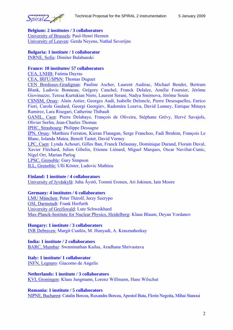
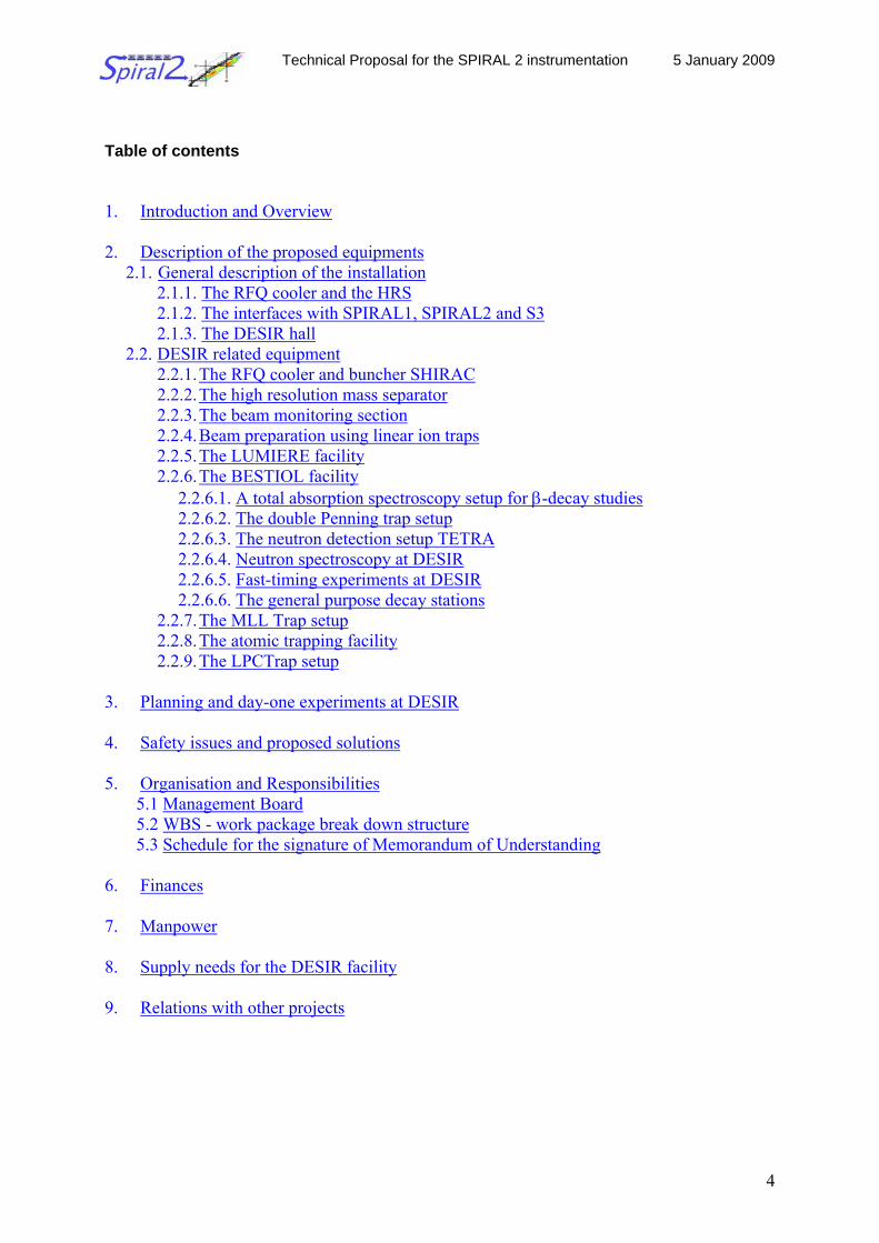
111 scientists and engineers co-sign the present technical report. They belong to 35 different institutes distributed over 15 countries (see Fig. 1). The collaboration list is displayed below:
Technical Proposal for the SPIRAL 2 instrumentation 5 January 2009
2
Belgium: 2 institutes / 3 collaborators University of Brussels: Paul-Henri Heenen University of Leuven: Gerda Neyens, Nathal Severijns Bulgaria: 1 institute / 1 collaborator INRNE, Sofia: Dimiter Balabanski France: 10 institutes/ 57 collaborators CEA, LNHB: Fatima Dayras CEA, IRFU/SPhN: Thomas Duguet CEN Bordeaux-Gradignan: Pauline Ascher, Laurent Audirac, Michael Bender, Bertram Blank, Ludovic Bonneau, Grégory Canchel, Franck Delalee, Amélie Fournier, Jérôme Giovinazzo, Teresa Kurtukian Nieto, Laurent Serani, Nadya Smirnova, Jérôme Souin CSNSM, Orsay: Alain Astier, Georges Audi, Isabelle Deloncle, Pierre Desesquelles, Enrico Fiori, Carole Gaulard, Georgi Georgiev, Radomira Lozeva, David Lunney, Enrique Minaya Ramirez, Lara Risegari, Catherine Thibault GANIL, Caen: Pierre Delahaye, François de Oliveira, Stéphane Grévy, Hervé Savajols, Olivier Sorlin, Jean-Charles Thomas IPHC, Strasbourg: Philippe Dessagne IPN, Orsay: Matthieu Ferraton, Kieran Flanagan, Serge Franchoo, Fadi Ibrahim, François Le Blanc, Iolanda Matea, Benoît Tastet, David Verney LPC, Caen: Lynda Achouri, Gilles Ban, Franck Delaunay, Dominique Durand, Florain Duval, Xavier Fléchard, Julien Gibelin, Etienne Liénard, Miguel Marques, Oscar Naviliat-Cunic, Nigel Orr, Marian Parlog LPSC, Grenoble: Gary Simpson ILL, Grenoble: Ulli Köster, Ludovic Mathieu Finland: 1 institute / 4 collaborators University of Jyväskylä: Juha Äystö, Tommi Eronen, Ari Jokinen, Iain Moore Germany: 4 institutes / 6 collaborators LMU München: Peter Thirolf, Jerzy Szerypo GSI, Darmstadt: Frank Herfurth University of Greifswald: Lutz Schweikhard Max-Planck-Institute for Nuclear Physics, Heidelberg: Klaus Blaum, Deyan Yordanov Hungary: 1 institute / 3 collaborators INR Debrecen: Margit Csatlós, M. Hunyadi, A. Krasznahorkay India: 1 institute / 2 collaborators BARC, Mumbai: Swaminathan Kailas, Aradhana Shrivastava Italy: 1 institute/ 1 collaborator INFN, Legnaro: Giacomo de Angelis Netherlands: 1 institute / 3 collaborators KVI, Groningen: Klaus Jungmann, Lorenz Willmann, Hans Wilschut Romania: 1 institute / 5 collaborators NIPNE, Bucharest: Catalin Borcea, Ruxandra Borcea, Apostol Buta, Florin Negoita, Mihai Stanoui
Technical Proposal for the SPIRAL 2 instrumentation 5 January 2009
3
Russia: 1 institute / 1 collaborator PNPI St. Petersburg: Leonid Batist Serbia: 1 institute / 4 collaborators Vinca Institute of Nuclear Sciences, Belgrade: Igor Celikovic, Laslo Nadjdjerdj , Krunoslav Subotic, Dragan Toprek Spain: 5 institutes/ 10 collaborators CIEMAT, Madrid: Daniel Cano Ott IEM, CSIC, Madrid: Maria Jose Garcia Borge, Andrea Jungclaus, Olof Tengblad University of Huelva: Ismael Martel, Daniel Rodriguez University Complutense of Madrid: Luis M. Fraile IFIC, CSIC, Valencia: Alejandro Algora, Berta Rubio, Jose L. Tain Switzerland: 1 institute / 2 collaborators ISOLDE-CERN: Alexander Herlert, Magdalena Kowalska United Kingdom: 4 institutes / 9 collaborators CCLRC, Daresbury: John Simpson University of Edinburgh: Phil Woods University of Manchester: Jon Billowes, Paul Campbell University of Surrey: Wilton Catford, Bill Gelletly, Zsolt Podolyak, Paddy Regan, Phil Walker
The DESIR Collaboration
France51,4%
Serbia3,6%
Belgium2,7%
Bulgaria0,9%
Russia0,9%
Italy0,9%
India1,8% Hungary
2,7%
Finland3,6%
Germany5,4%
Switzerland1,8%
U.K.8,1%
Netherlands2,7%
Romania4,5%
Spain9,0%
Figure 1: The DESIR collaborators by countries
Technical Proposal for the SPIRAL 2 instrumentation 5 January 2009
4
Table of contents 1. Introduction and Overview 2. Description of the proposed equipments
2.1. General description of the installation 2.1.1. The RFQ cooler and the HRS 2.1.2. The interfaces with SPIRAL1, SPIRAL2 and S3 2.1.3. The DESIR hall
2.2. DESIR related equipment 2.2.1. The RFQ cooler and buncher SHIRAC 2.2.2. The high resolution mass separator 2.2.3. The beam monitoring section 2.2.4. Beam preparation using linear ion traps 2.2.5. The LUMIERE facility 2.2.6. The BESTIOL facility
2.2.6.1. A total absorption spectroscopy setup for β-decay studies 2.2.6.2. The double Penning trap setup 2.2.6.3. The neutron detection setup TETRA 2.2.6.4. Neutron spectroscopy at DESIR 2.2.6.5. Fast-timing experiments at DESIR 2.2.6.6. The general purpose decay stations
2.2.7. The MLL Trap setup 2.2.8. The atomic trapping facility 2.2.9. The LPCTrap setup
3. Planning and day-one experiments at DESIR 4. Safety issues and proposed solutions 5. Organisation and Responsibilities
5.1 Management Board 5.2 WBS - work package break down structure 5.3 Schedule for the signature of Memorandum of Understanding
6. Finances 7. Manpower 8. Supply needs for the DESIR facility 9. Relations with other projects
Technical Proposal for the SPIRAL 2 instrumentation 5 January 2009
5
1 Introduction and Overview To date only about half of the nuclei predicted theoretically to exist are known experimentally. Often the key nuclei are the most exotic systems (large proton to neutron asymmetry) because they allow the isolation and amplification of specific terms of nucleonic interactions. Exotic nuclei, near the drip lines, are loosely bound systems which lead to such unusual topologies as halo nuclei and to changes in the nuclear mean field potential even at the so-called magic numbers. Moreover the proximity of the unbound continuum can lead to important changes in residual interactions. It is therefore important to produce and study these new nuclear species. At GANIL, these nuclei will be produced by different mechanisms. With SPIRAL2, the medium-mass neutron-rich isotopes will be produced by neutron-induced fission of 238U. The high intensity stable beams of heavy ions provided by the LINAG will allow producing very exotic isotopes along the N~Z line, including refractory elements, as well as heavy isotopes in the transactinide region, using fusion-evaporation reactions and the S3 separator-spectrometer. The existing SPIRAL1 facility will deliver intense radioactive beams of light ions produced in fragmentation reactions. Finally, transfer and deep-inelastic reactions are foreseen for the production of light to heavier nuclei close to the stability. All these beams will be delivered to the DESIR facility, the proposed low-energy installation of GANIL. Two major physics topics will be addressed at the DESIR facility, namely the studies related to nuclear structure and astrophysics and the studies related to the Standard Model. In the following, a summary of these topics is given.
On the nuclear structure side, low-energy beams of exotic nuclei allow different types of
experiments. By combining a variety of experimental tools, complementary studies of properties of exotic nuclei are done to investigate their nuclear structure and their impact on astrophysics scenarios. As an example, it is well establish that the evolution of single-particle energies plays an important role in determining the effective interactions between valence particles. In weakly-bound systems, the spin-orbit force is expected to be weaker and shell gaps arising from this force should disappear. In the region of medium-heavy nuclei, new magic numbers might also appear for nuclei with a large N/Z ratio. The change in orbital ordering is most likely caused by the strongly attractive neutron-proton interaction between spin-orbit partners.
With intensities as low as few particles per second, global information like the half life
as well as information about the different decay modes can be extracted. With higher counting rates, more precise measurement are possible. β-decay to states in the daughter nucleus gives access to the degree of overlap between the neutron and proton states in the parent and daughter nuclei. Simultaneously, the observation of γ radiations from excited states will yield invaluable spectroscopic information on the energies and characteristics of the low-lying excited states. This spectrum of states permits the characterization of the structure of the nucleus in terms of rigidity, deformation and arrangement of the nucleons. β-decay is also the first approach to study new nuclear species along the r-process path. These exotic nuclei which are far beyond the reach of current accelerator facilities play a role in astrophysical processes and SPIRAL2 offers the possibility to reach some of the lighter cases. The nuclei very far from the stability are also characterized by large β-decay Q values and relatively small nucleon-separation energies. Therefore, the β-decay of exotic nuclei may feed excited states that are unbound with respect to the emission of nucleons or clusters of nucleons. The key point is that, if one knows the final state, one can derive the β feeding to that state and the associated Fermi or Gamow-Teller (GT) matrix elements from the particle spectra. This yields information on the strong interaction inside the nucleus. Another information which often
Technical Proposal for the SPIRAL 2 instrumentation 5 January 2009
6
points out to changes in the structure of the exotic nuclei is the mass. An important number of new species will be available at the DESIR facility to perform such measurements. With reasonably high beam intensities, trap-assisted decay spectroscopy with ultra-pure samples becomes possible. In these measurements, the radioactive samples are accumulated in a trap, purified and finally ejected toward a measurement station. Also the daughter products can be trapped and then offer access to species otherwise unobtainable from thick targets (e.g. refractory elements). Decay Q-values can be determined in this way and, hence, binding energies of exotic nuclides.
Other important observables that can be measured with few thousand of particles per
second are the nuclear static moments (radii, magnetic dipole, and electric quadrupole). They are derived from the observation of the magnetic and electrostatic hyperfine structure in optical spectra as well as the influence of the nuclear charge radii on the isotope shifts between different isotopes of a given element. Moreover, these moments can also be determined in a model independent way thus providing direct information on the nuclear structure (occupation of single particle orbits, collectivity and deformation…). Therefore, the measurement of nuclear moments is a stringent test for nuclear models. By combining this information with a β-NMR measurement (g factor), it is possible to unambiguously assign the spin of nuclear ground and excited states. It is particularly important in regions far from stability to firmly assign the spin of a few nuclear states, in order to deduce information on the spins of their mother or daughters via e.g. β-decay spectroscopy experiments. β-NMR measurements yield the nuclear moments with a precision better than 0.1% (for g-factor) and 1% (for Q-moment), thus allowing probing small changes in the nuclear wave function, contributions from particle-hole excitations and intruder configurations in the wave function, core polarization effects, etc. Finally, high-precision measurements of the hyperfine anomaly allows quantifying the influence of the nuclear magnetic distribution on the hyperfine structure, which addresses more precisely the effects of parity non-conservation in isotopic series and the contribution of the neutrons to the nuclear wave function. The combination of laser and microwave spectroscopy in a Paul trap gives the necessary precision of the order of 10-9 on the magnetic hyperfine constant and allows reaching the 3rd and 4th order of the hyperfine interaction. Thus higher-order nuclear moments associated with deformations of octupole and hexadecapole character can be investigated in heavy elements. Such studies should be very interesting in the gold isotopes where the hyperfine anomaly can vary between 1 and 10 %.
Fundamental studies related to the Standard Model (SM) often require important statistics (>1000 pps). Searches for deviations from unitarity of the CKM quark-mixing matrix provide very stringent tests of the Standard Model of electroweak interactions, which could point to the presence of new physics. So far, high-precision measurements of super-allowed (Fermi) β-decay properties provide the most precise determination of the Vud matrix element leading to the most stringent unitarity test of the CKM matrix. Pure Fermi transitions are intrinsically simple and can therefore be precisely described by theory. However, as these decays take place in the nuclear medium, corrections are necessary for a comparison between the theoretical predictions and experimental results. The required level of precision has been achieved to date for 13 nuclei and needs to be extended to other nuclei for an improved understanding of the theoretical corrections. New data for lighter nuclei is also of great importance for improved tests of the electroweak interaction.
With higher beam intensities, the structure of the weak interaction can be studied by
angular correlation measurements. The vector and axial-vector structure of weak interactions
Technical Proposal for the SPIRAL 2 instrumentation 5 January 2009
7
has been imbedded in the Standard Model where the interaction between leptons and quarks is described by the exchange of charged weak vector bosons. Several extensions to the SM introduce new exchange bosons, which would be revealed by the presence of scalar and tensor interactions in nuclear β decay. A robust observable for the structure of the weak interaction is the angular correlation between the emitted leptons deduced from the observation in coincidence of the electron (or positron) and the recoiling nucleus. This correlation probes the presence of exotic couplings without assumptions on their discrete space and time transformation properties. The availability of very high intensity radioactive beams enables the consideration of new techniques beyond atom and ion traps, in which the angular correlation is determined from the measurement of decays in flight from a very low energy beam with small transverse size. Such techniques require dedicated beam preparation in order to achieve a number of decays of about 1000 per second over the beam volume seen by the detectors.
Finally, DESIR will allow to perform experiments to search for symmetry violations.
Observables which are odd under the space inversion (parity) or time reversal transformations provide a simple means to search for deviations from maximal parity violation in the weak interaction or for new sources of T (or CP) violation in the strangeness-conserving sector probed by β-decay experiments. Many scenarios beyond the SM predict the restoration of parity symmetry at some higher energy scale or the presence of new CP-violating phases beyond the standard electroweak CP phase of the CKM matrix. Precision experiments at low energies can often probe energy scales not otherwise accessible and are hence complementary to the searches for new physics performed at the highest possible energies. Significant improvements have been achieved in measurements of the longitudinal and transverse polarizations of β particles from polarized nuclei and in other correlation parameters in nuclear and neutron decays. New exploratory experiments for parity and time-reversal symmetry tests have been performed using atom traps in which the radioactive atoms were polarized with lasers. Other tests involve interference effects with the electromagnetic interaction in atoms (PNC) and the search for non-permanent electric dipole moments. In general, the sensitivity to symmetry violations in atoms is strongly enhanced for isotopes with high atomic numbers, possibly radioactive. 2 Description of the proposed equipments The DESIR collaboration was established after a workshop on low-energy physics held at GANIL in July 2005. The DESIR facility was first presented in a Letter of Intent to the SPIRAL2 Scientific Advisory Committee in 2006 [DESIR]. It is part of the new equipment proposed to use the radioactive beams produced by SPIRAL2, but DESIR is also designed to take beam from SPIRAL1 via the LIRAT beam line and from the separator-spectrometer S3.
DESIR is part of Phase 2 of the construction program of SPIRAL2. Although the financing of the general components of DESIR like the HRS, the DESIR building and the beam lines to and in DESIR is still rather unclear, it was decided to continue the detailed studies of the construction program and of the general scheme for radioprotection around DESIR in the context of phase 2 of SPIRAL2. By mid-2010, a decision about the construction of DESIR has to be taken. If the financing arrives in time, DESIR could take beam from SPIRAL1, SPIRAL2 and S3 as early as 2013. [DESIR] http://www.ganil.fr/spiral2/files/LoIs_SP2_final/LoI_SP2_1_DESIR_final.pdf
Technical Proposal for the SPIRAL 2 instrumentation 5 January 2009
8
LIRAT
S3
DDEESSIIRR
Level -8
Level -8
LINAG
N F S
15 m
Production building GANIL/
SPIRAL
RRFFQQ ++ HHRRSS
2.1 General description of the installation
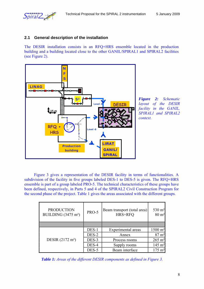
The DESIR installation consists in an RFQ+HRS ensemble located in the production building and a building located close to the other GANIL/SPIRAL1 and SPIRAL2 facilities (see Figure 2).
Figure 2: Schematic layout of the DESIR facility in the GANIL, SPIRAL1 and SPIRAL2 context.
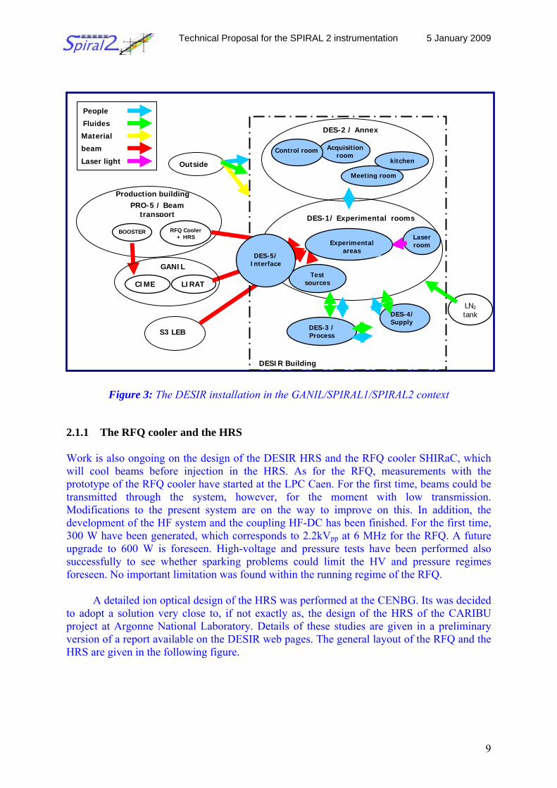
Figure 3 gives a representation of the DESIR facility in terms of functionalities. A subdivision of the facility in five groups labeled DES-1 to DES-5 is given. The RFQ+HRS ensemble is part of a group labeled PRO-5. The technical characteristics of these groups have been defined, respectively, in Parts 5 and 4 of the SPIRAL2 Civil Construction Program for the second phase of the project. Table 1 gives the areas associated with the different groups.
Table 1: Areas of the different DESIR components as defined in Figure 3.
PRODUCTION BUILDING (3475 m²) PRO-5 Beam transport (total area)
HRS+RFQ 530 m² 80 m²
DES-1 Experimental areas 1500 m² DES-2 Annex 87 m² DES-3 Process rooms 265 m² DES-4 Supply rooms 145 m²
DESIR (2172 m²)
DES-5 Beam interface 175 m²
Technical Proposal for the SPIRAL 2 instrumentation 5 January 2009
9
DES-1/ Experimental rooms
DES-2 / Annex
Control room Acquisition room
Meeting room
kitchen Outside
People
Test sources
LN2 tank
Fluides
Material
RFQ Cooler + HRS
LIRAT
Production building
BOOSTER Laser room
beam
CIME
GANIL
DES-3 / Process
DES-4/ Supply
S3 LEB
Laser light
DESIR Building
Experimental areas
PRO-5 / Beam transport
DES-5/ Interface
Figure 3: The DESIR installation in the GANIL/SPIRAL1/SPIRAL2 context
2.1.1 The RFQ cooler and the HRS
Work is also ongoing on the design of the DESIR HRS and the RFQ cooler SHIRaC, which will cool beams before injection in the HRS. As for the RFQ, measurements with the prototype of the RFQ cooler have started at the LPC Caen. For the first time, beams could be transmitted through the system, however, for the moment with low transmission. Modifications to the present system are on the way to improve on this. In addition, the development of the HF system and the coupling HF-DC has been finished. For the first time, 300 W have been generated, which corresponds to 2.2kVpp at 6 MHz for the RFQ. A future upgrade to 600 W is foreseen. High-voltage and pressure tests have been performed also successfully to see whether sparking problems could limit the HV and pressure regimes foreseen. No important limitation was found within the running regime of the RFQ.
A detailed ion optical design of the HRS was performed at the CENBG. Its was decided to adopt a solution very close to, if not exactly as, the design of the HRS of the CARIBU project at Argonne National Laboratory. Details of these studies are given in a preliminary version of a report available on the DESIR web pages. The general layout of the RFQ and the HRS are given in the following figure.
Technical Proposal for the SPIRAL 2 instrumentation 5 January 2009
10
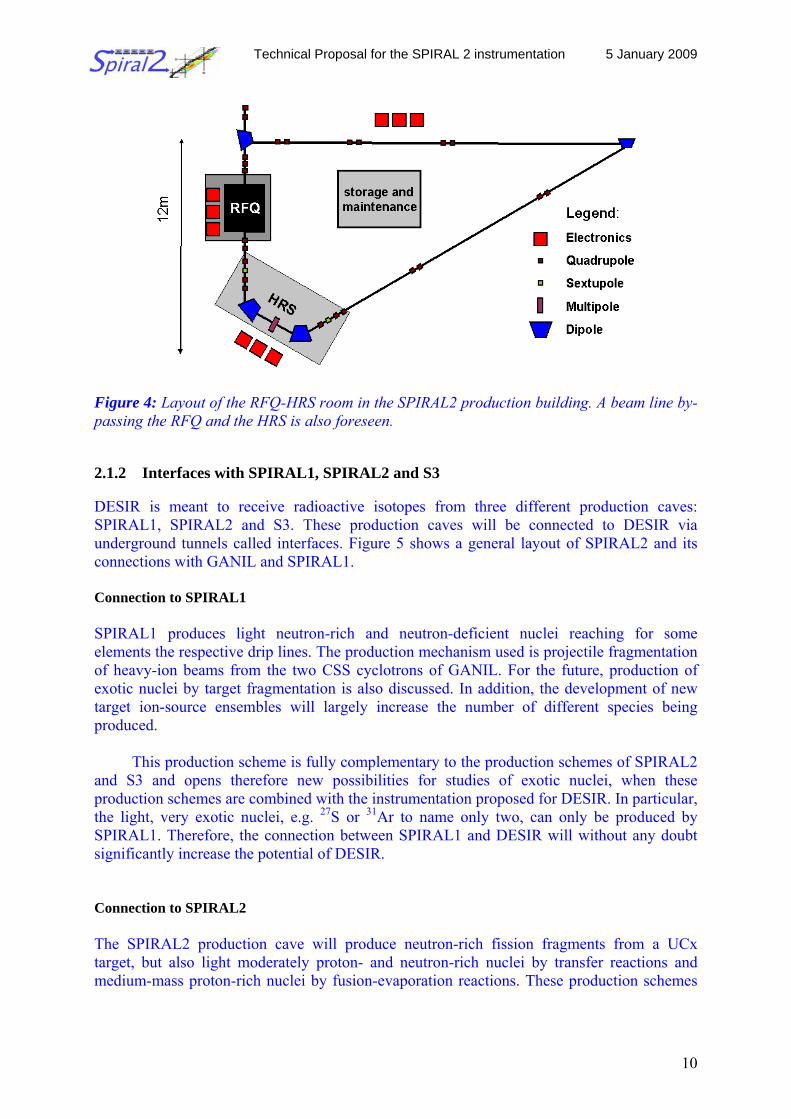
Figure 4: Layout of the RFQ-HRS room in the SPIRAL2 production building. A beam line by-passing the RFQ and the HRS is also foreseen. 2.1.2 Interfaces with SPIRAL1, SPIRAL2 and S3 DESIR is meant to receive radioactive isotopes from three different production caves: SPIRAL1, SPIRAL2 and S3. These production caves will be connected to DESIR via underground tunnels called interfaces. Figure 5 shows a general layout of SPIRAL2 and its connections with GANIL and SPIRAL1. Connection to SPIRAL1 SPIRAL1 produces light neutron-rich and neutron-deficient nuclei reaching for some elements the respective drip lines. The production mechanism used is projectile fragmentation of heavy-ion beams from the two CSS cyclotrons of GANIL. For the future, production of exotic nuclei by target fragmentation is also discussed. In addition, the development of new target ion-source ensembles will largely increase the number of different species being produced.
This production scheme is fully complementary to the production schemes of SPIRAL2
and S3 and opens therefore new possibilities for studies of exotic nuclei, when these production schemes are combined with the instrumentation proposed for DESIR. In particular, the light, very exotic nuclei, e.g. 27S or 31Ar to name only two, can only be produced by SPIRAL1. Therefore, the connection between SPIRAL1 and DESIR will without any doubt significantly increase the potential of DESIR. Connection to SPIRAL2 The SPIRAL2 production cave will produce neutron-rich fission fragments from a UCx target, but also light moderately proton- and neutron-rich nuclei by transfer reactions and medium-mass proton-rich nuclei by fusion-evaporation reactions. These production schemes
Technical Proposal for the SPIRAL 2 instrumentation 5 January 2009
11
open unique possibilities for the study of exotic nuclei, when combined with the experimental setups available at DESIR.
The different types of ion sources, a surface ionization source, a FEBIAD source, an
ECR source and a Laser ion source, will produce a large variety of different, sufficiently volatile elements from the lightest to most heavy elements close to uranium. The different production mechanisms combined with the different ion sources will allow to systematically study long isotopic or isotonic chains with Laser spectroscopy and other methods.
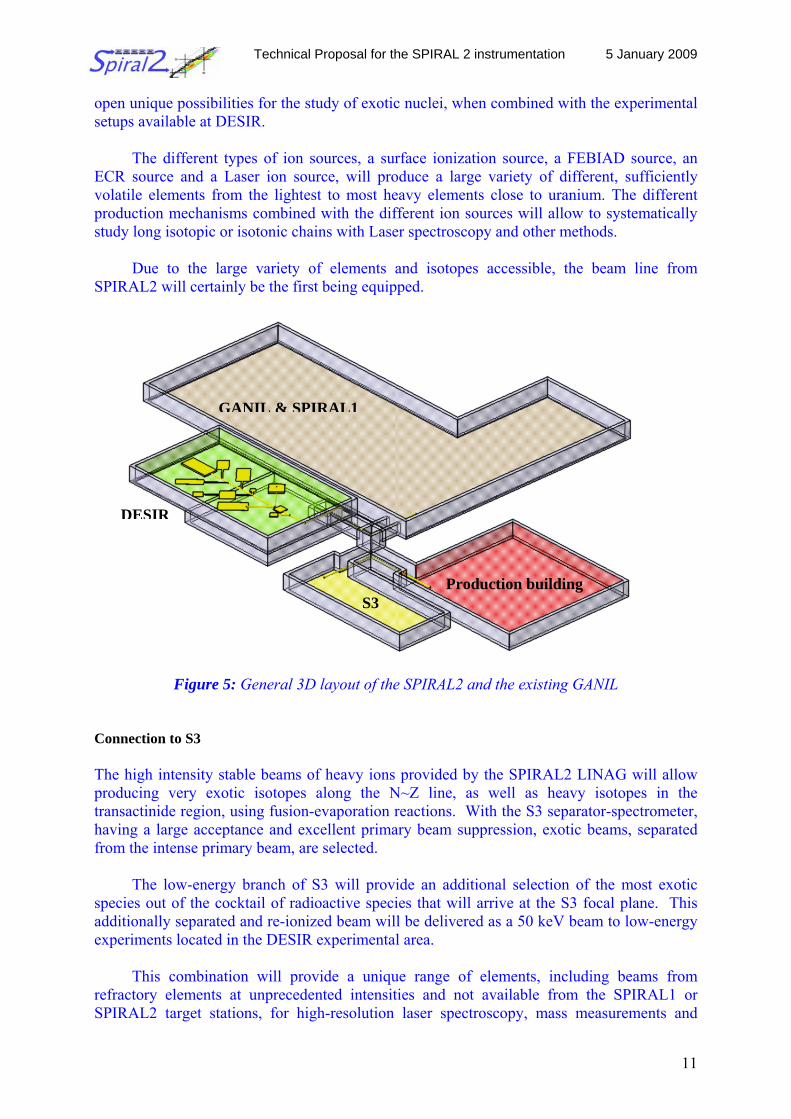
Due to the large variety of elements and isotopes accessible, the beam line from
SPIRAL2 will certainly be the first being equipped.
Figure 5: General 3D layout of the SPIRAL2 and the existing GANIL
Connection to S3 The high intensity stable beams of heavy ions provided by the SPIRAL2 LINAG will allow producing very exotic isotopes along the N~Z line, as well as heavy isotopes in the transactinide region, using fusion-evaporation reactions. With the S3 separator-spectrometer, having a large acceptance and excellent primary beam suppression, exotic beams, separated from the intense primary beam, are selected.
The low-energy branch of S3 will provide an additional selection of the most exotic species out of the cocktail of radioactive species that will arrive at the S3 focal plane. This additionally separated and re-ionized beam will be delivered as a 50 keV beam to low-energy experiments located in the DESIR experimental area.
This combination will provide a unique range of elements, including beams from
refractory elements at unprecedented intensities and not available from the SPIRAL1 or SPIRAL2 target stations, for high-resolution laser spectroscopy, mass measurements and
GANIL & SPIRAL1
Production building S3
DESIR
Technical Proposal for the SPIRAL 2 instrumentation 5 January 2009
12
decay studies, thus opening regions on the nuclear chart which are accessible at no other facility worldwide at these intensities.
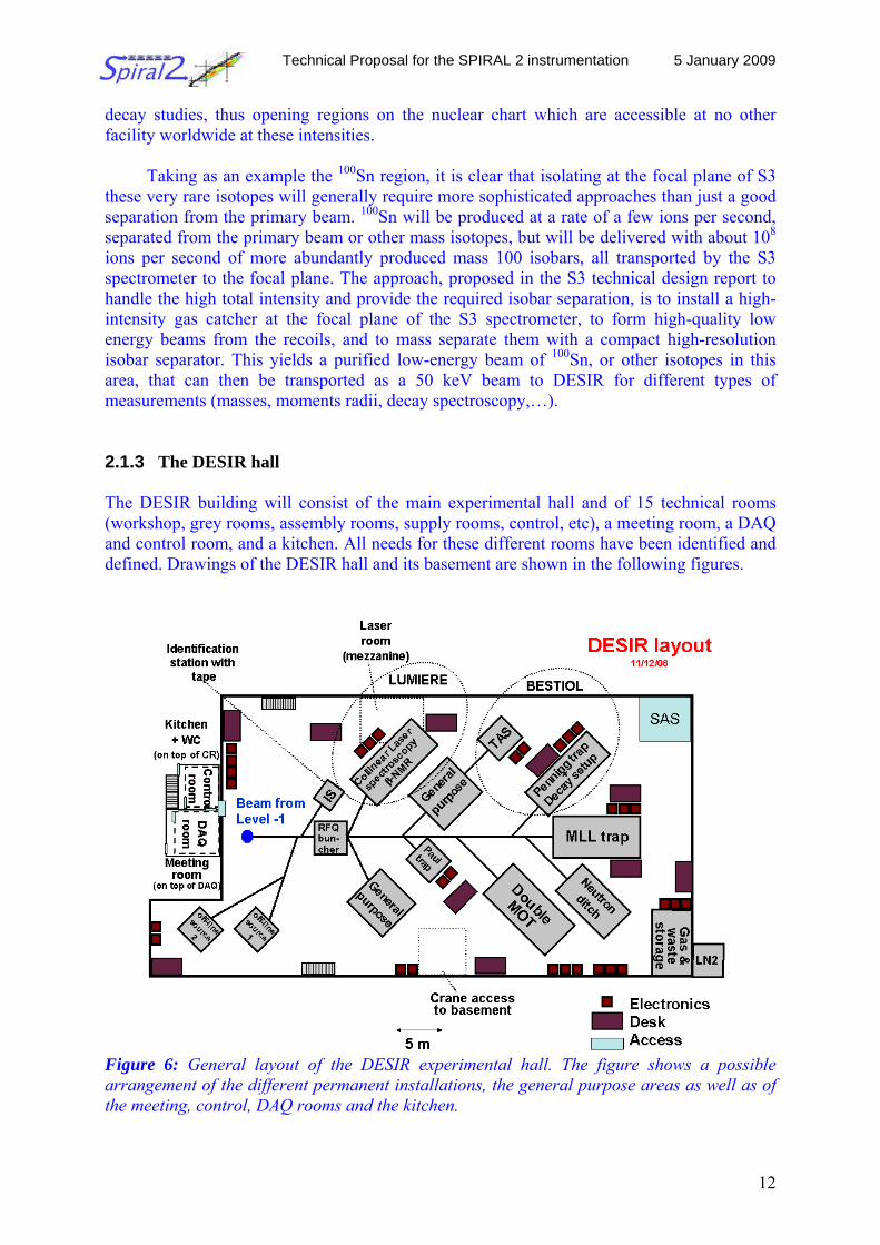
Taking as an example the 100Sn region, it is clear that isolating at the focal plane of S3 these very rare isotopes will generally require more sophisticated approaches than just a good separation from the primary beam. 100Sn will be produced at a rate of a few ions per second, separated from the primary beam or other mass isotopes, but will be delivered with about 108 ions per second of more abundantly produced mass 100 isobars, all transported by the S3 spectrometer to the focal plane. The approach, proposed in the S3 technical design report to handle the high total intensity and provide the required isobar separation, is to install a high-intensity gas catcher at the focal plane of the S3 spectrometer, to form high-quality low energy beams from the recoils, and to mass separate them with a compact high-resolution isobar separator. This yields a purified low-energy beam of 100Sn, or other isotopes in this area, that can then be transported as a 50 keV beam to DESIR for different types of measurements (masses, moments radii, decay spectroscopy,…). 2.1.3 The DESIR hall The DESIR building will consist of the main experimental hall and of 15 technical rooms (workshop, grey rooms, assembly rooms, supply rooms, control, etc), a meeting room, a DAQ and control room, and a kitchen. All needs for these different rooms have been identified and defined. Drawings of the DESIR hall and its basement are shown in the following figures.
Figure 6: General layout of the DESIR experimental hall. The figure shows a possible arrangement of the different permanent installations, the general purpose areas as well as of the meeting, control, DAQ rooms and the kitchen.
Technical Proposal for the SPIRAL 2 instrumentation 5 January 2009
13
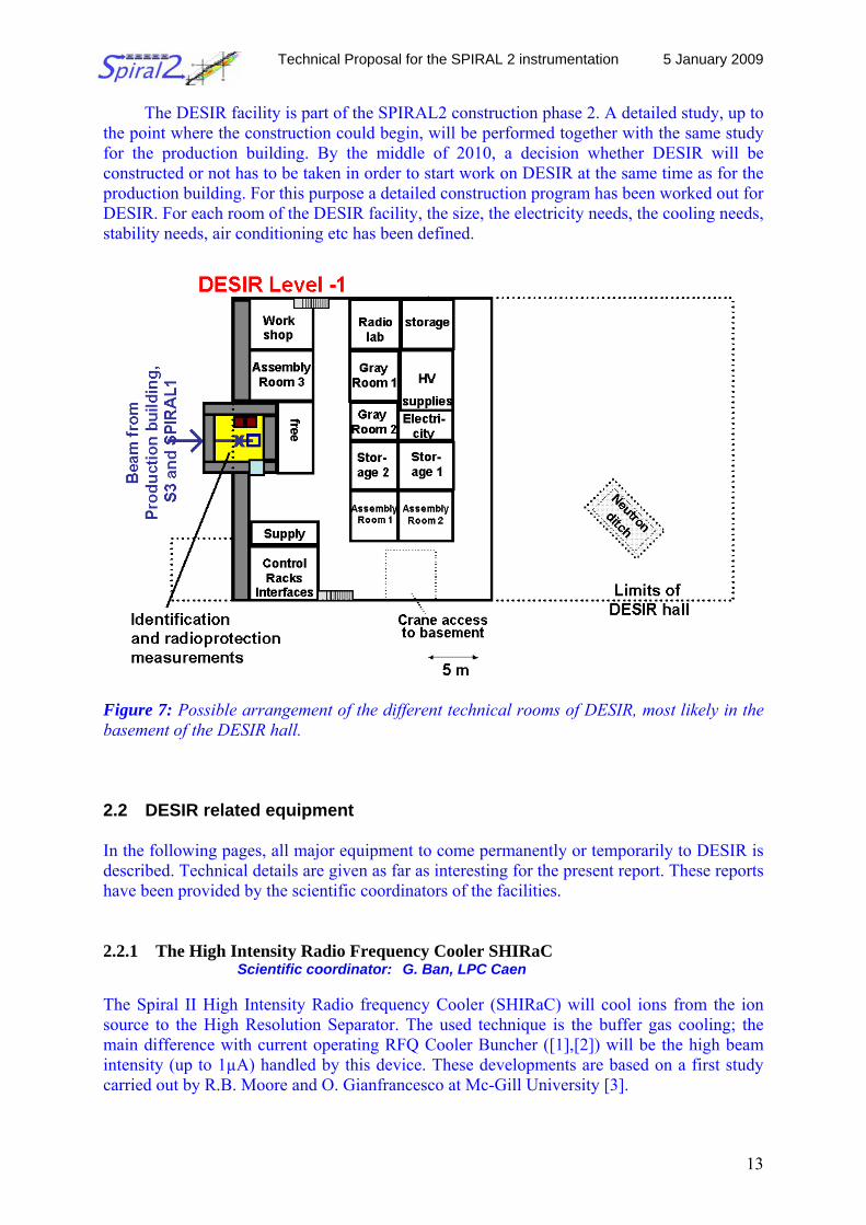
The DESIR facility is part of the SPIRAL2 construction phase 2. A detailed study, up to the point where the construction could begin, will be performed together with the same study for the production building. By the middle of 2010, a decision whether DESIR will be constructed or not has to be taken in order to start work on DESIR at the same time as for the production building. For this purpose a detailed construction program has been worked out for DESIR. For each room of the DESIR facility, the size, the electricity needs, the cooling needs, stability needs, air conditioning etc has been defined.
Figure 7: Possible arrangement of the different technical rooms of DESIR, most likely in the basement of the DESIR hall. 2.2 DESIR related equipment
In the following pages, all major equipment to come permanently or temporarily to DESIR is described. Technical details are given as far as interesting for the present report. These reports have been provided by the scientific coordinators of the facilities.
2.2.1 The High Intensity Radio Frequency Cooler SHIRaC Scientific coordinator: G. Ban, LPC Caen The Spiral II High Intensity Radio frequency Cooler (SHIRaC) will cool ions from the ion source to the High Resolution Separator. The used technique is the buffer gas cooling; the main difference with current operating RFQ Cooler Buncher ([1],[2]) will be the high beam intensity (up to 1µA) handled by this device. These developments are based on a first study carried out by R.B. Moore and O. Gianfrancesco at Mc-Gill University [3].
Technical Proposal for the SPIRAL 2 instrumentation 5 January 2009
14
Technical specifications
- Beam intensity up to 1µA of single charged ions. - Maximum ion energy 60 keV. - Acceptance ~ 80 π.mm.mrad. - Output emittance ~1 π.mm.mrad. - Energy dispersion less than 1eV @60 keV. - Transmission:
- At least 20% for masses over 12. - At least 40% for masses over 40. - At least 60% for masses over 90. - Yellow-area operation. Main Components Quadrupole: The quadrupole consists of four segmented rods with a diameter of 5.7 mm and a total length of 725 mm. They will be made in stainless steel, with a roughness Ra lower than 0.1 µm (etching polishing).
There will be 18 segments. Each rod will be attached to a rectangular steel bar on
which the RF voltage will be applied. The whole quadrupole is set on a flange and the quadrupole structure can be extracted for maintenance. All the electrical feedthroughs are set on this flange. There will be simple electrostatic lenses at the injection and at the extraction.
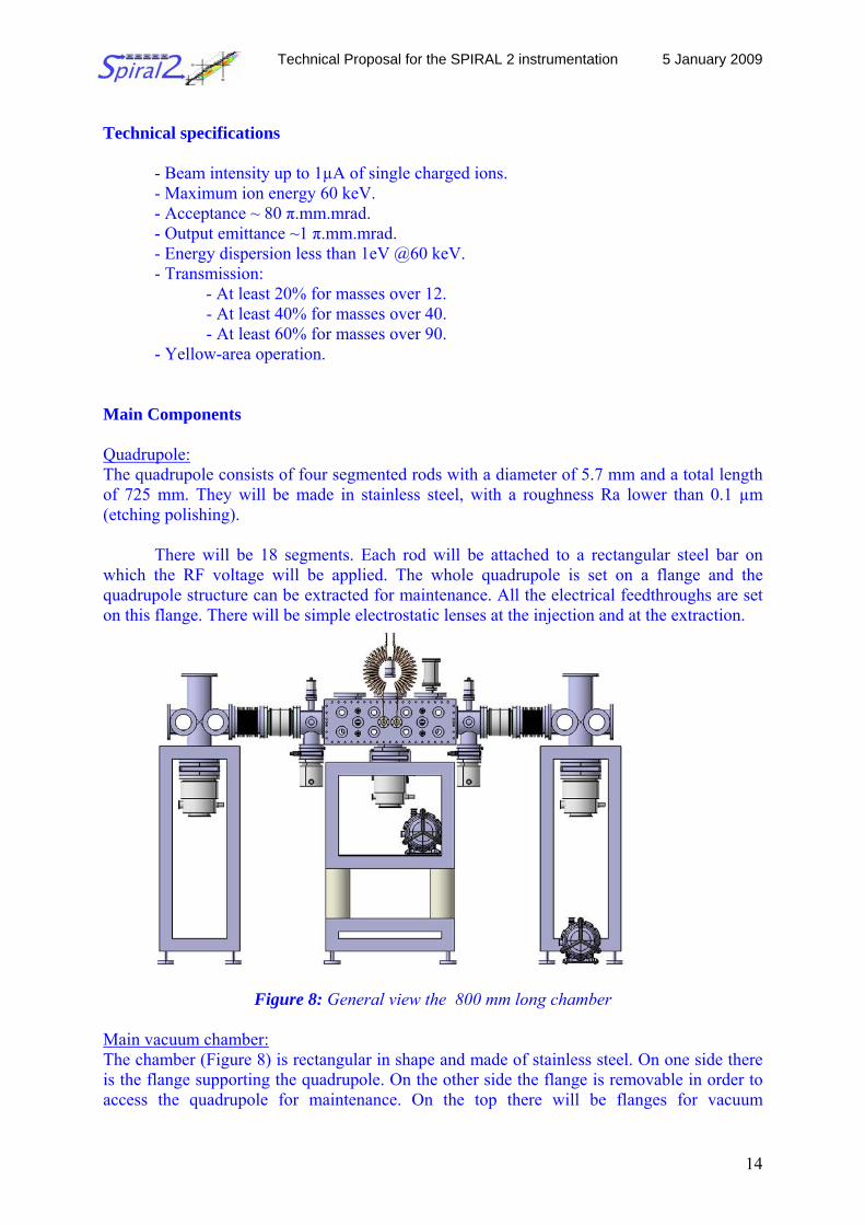
Figure 8: General view the 800 mm long chamber Main vacuum chamber: The chamber (Figure 8) is rectangular in shape and made of stainless steel. On one side there is the flange supporting the quadrupole. On the other side the flange is removable in order to access the quadrupole for maintenance. On the top there will be flanges for vacuum
Technical Proposal for the SPIRAL 2 instrumentation 5 January 2009
15
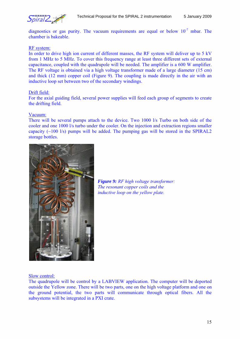
diagnostics or gas purity. The vacuum requirements are equal or below 10-7 mbar. The chamber is bakeable. RF system: In order to drive high ion current of different masses, the RF system will deliver up to 5 kV from 1 MHz to 5 MHz. To cover this frequency range at least three different sets of external capacitance, coupled with the quadrupole will be needed. The amplifier is a 600 W amplifier. The RF voltage is obtained via a high voltage transformer made of a large diameter (15 cm) and thick (12 mm) copper coil (Figure 9). The coupling is made directly in the air with an inductive loop set between two of the secondary windings. Drift field: For the axial guiding field, several power supplies will feed each group of segments to create the drifting field. Vacuum: There will be several pumps attach to the device. Two 1000 l/s Turbo on both side of the cooler and one 1000 l/s turbo under the cooler. On the injection and extraction regions smaller capacity (~100 l/s) pumps will be added. The pumping gas will be stored in the SPIRAL2 storage bottles.
Figure 9: RF high voltage transformer: The resonant copper coils and the inductive loop on the yellow plate.
Slow control: The quadrupole will be control by a LABVIEW application. The computer will be deported outside the Yellow zone. There will be two parts, one on the high voltage platform and one on the ground potential, the two parts will communicate through optical fibers. All the subsystems will be integrated in a PXI crate.
Technical Proposal for the SPIRAL 2 instrumentation 5 January 2009
16
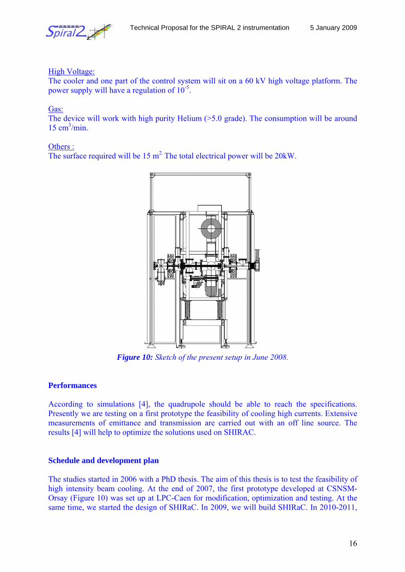
High Voltage: The cooler and one part of the control system will sit on a 60 kV high voltage platform. The power supply will have a regulation of 10-5.
Gas: The device will work with high purity Helium (>5.0 grade). The consumption will be around 15 cm3/min.
Others : The surface required will be 15 m2. The total electrical power will be 20kW.
Figure 10: Sketch of the present setup in June 2008.
Performances According to simulations [4], the quadrupole should be able to reach the specifications. Presently we are testing on a first prototype the feasibility of cooling high currents. Extensive measurements of emittance and transmission are carried out with an off line source. The results [4] will help to optimize the solutions used on SHIRAC. Schedule and development plan The studies started in 2006 with a PhD thesis. The aim of this thesis is to test the feasibility of high intensity beam cooling. At the end of 2007, the first prototype developed at CSNSM-Orsay (Figure 10) was set up at LPC-Caen for modification, optimization and testing. At the same time, we started the design of SHIRaC. In 2009, we will build SHIRaC. In 2010-2011,
Technical Proposal for the SPIRAL 2 instrumentation 5 January 2009
17
we will test and assess the performance of the cooler. If necessary, we will modify the present design to cope with the yellow zone requirements.
Cost For the non yellow zone version the total cost for SHIRAC is 350 k€. When the technical solutions for the yellow zone will be known, we will project a cost for the yellow zone version. Whatever the solution for the yellow zone, only the vacuum components will not be reused; all the electronics, the slow control and the pumping system should be the same. References [1] A. Nieminem et al., Nucl. Instr. and Meth. A469 (2001) 244 [2] F. Herfurth et al., Nucl. Instr. and Meth. A 469 (2001) 254 [3] O Gianfrancesco. Masters Thesis. Mc Gill University. 2002 [4] F. Duval, PhD thesis 2009
2.2.2 The high resolution mass separator
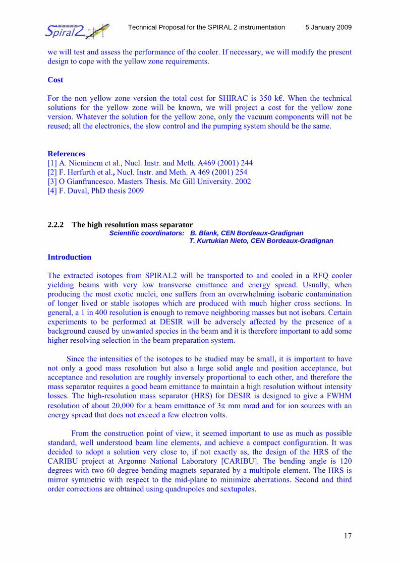
Scientific coordinators: B. Blank, CEN Bordeaux-Gradignan T. Kurtukian Nieto, CEN Bordeaux-Gradignan
Introduction The extracted isotopes from SPIRAL2 will be transported to and cooled in a RFQ cooler yielding beams with very low transverse emittance and energy spread. Usually, when producing the most exotic nuclei, one suffers from an overwhelming isobaric contamination of longer lived or stable isotopes which are produced with much higher cross sections. In general, a 1 in 400 resolution is enough to remove neighboring masses but not isobars. Certain experiments to be performed at DESIR will be adversely affected by the presence of a background caused by unwanted species in the beam and it is therefore important to add some higher resolving selection in the beam preparation system.
Since the intensities of the isotopes to be studied may be small, it is important to have not only a good mass resolution but also a large solid angle and position acceptance, but acceptance and resolution are roughly inversely proportional to each other, and therefore the mass separator requires a good beam emittance to maintain a high resolution without intensity losses. The high-resolution mass separator (HRS) for DESIR is designed to give a FWHM resolution of about 20,000 for a beam emittance of 3π mm mrad and for ion sources with an energy spread that does not exceed a few electron volts.
From the construction point of view, it seemed important to use as much as possible standard, well understood beam line elements, and achieve a compact configuration. It was decided to adopt a solution very close to, if not exactly as, the design of the HRS of the CARIBU project at Argonne National Laboratory [CARIBU]. The bending angle is 120 degrees with two 60 degree bending magnets separated by a multipole element. The HRS is mirror symmetric with respect to the mid-plane to minimize aberrations. Second and third order corrections are obtained using quadrupoles and sextupoles.
Technical Proposal for the SPIRAL 2 instrumentation 5 January 2009
18
Technical specifications The system has to have the following characteristics:
1. High transmission (ideally close to 100%) and high resolving power (m/Δm ~20000) to provide monoisotopic beams of exotic nuclides
2. Match beam emittance from RFQ cooler (ε<3π mm-mrad, ΔE<1 eV at 60 keV)
3. Compact configuration (12 m x 8 m). Must fit in the SPIRAL2 production building
4. Should be robust in order to tolerate errors in alignment and component manufacturing
5. Cheep, concerning both installation and operation costs
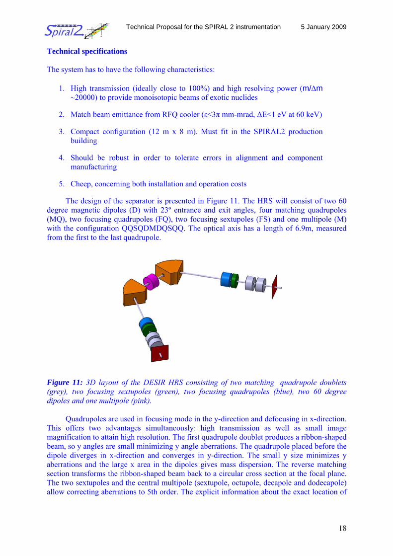
The design of the separator is presented in Figure 11. The HRS will consist of two 60 degree magnetic dipoles (D) with 23º entrance and exit angles, four matching quadrupoles (MQ), two focusing quadrupoles (FQ), two focusing sextupoles (FS) and one multipole (M) with the configuration QQSQDMDQSQQ. The optical axis has a length of 6.9m, measured from the first to the last quadrupole.
Figure 11: 3D layout of the DESIR HRS consisting of two matching quadrupole doublets (grey), two focusing sextupoles (green), two focusing quadrupoles (blue), two 60 degree dipoles and one multipole (pink).
Quadrupoles are used in focusing mode in the y-direction and defocusing in x-direction.
This offers two advantages simultaneously: high transmission as well as small image magnification to attain high resolution. The first quadrupole doublet produces a ribbon-shaped beam, so y angles are small minimizing y angle aberrations. The quadrupole placed before the dipole diverges in x-direction and converges in y-direction. The small y size minimizes y aberrations and the large x area in the dipoles gives mass dispersion. The reverse matching section transforms the ribbon-shaped beam back to a circular cross section at the focal plane. The two sextupoles and the central multipole (sextupole, octupole, decapole and dodecapole) allow correcting aberrations to 5th order. The explicit information about the exact location of
Technical Proposal for the SPIRAL 2 instrumentation 5 January 2009
19
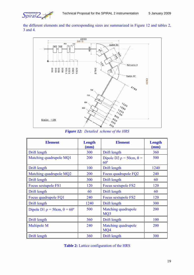
the different elements and the corresponding sizes are summarized in Figure 12 and tables 2, 3 and 4.
Figure 12: Detailed scheme of the HRS
Table 2: Lattice configuration of the HRS
Element Length (mm)
Element Length (mm)
Drift length 300 Drift length 360 Matching quadrupole MQ1 200 Dipole D2 ρ = 50cm, θ =
60º 500
Drift length 100 Drift length 1240 Matching quadrupole MQ2 200 Focus quadrupole FQ2 240 Drift length 300 Drift length 60 Focus sextupole FS1 120 Focus sextupole FS2 120 Drift length 60 Drift length 60 Focus quadrupole FQ1 240 Focus sextupole FS2 120 Drift length 1240 Drift length 300 Dipole D1 ρ = 50cm, θ = 60º 500 Matching quadrupole
MQ3 200
Drift length 360 Drift length 100 Multipole M 240 Matching quadrupole
MQ4 200
Drift length 360 Drift length 300
Technical Proposal for the SPIRAL 2 instrumentation 5 January 2009
20
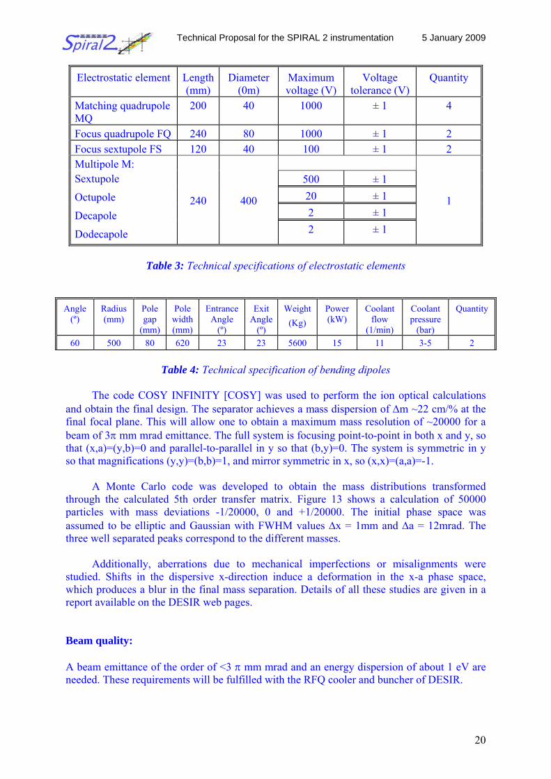
Electrostatic element Length (mm)
Diameter (0m)
Maximum voltage (V)
Voltage tolerance (V)
Quantity
Matching quadrupole MQ
200 40 1000 ± 1 4
Focus quadrupole FQ 240 80 1000 ± 1 2 Focus sextupole FS 120 40 100 ± 1 2
500 ± 1 20 ± 1 2 ± 1
Multipole M: Sextupole
Octupole
Decapole
Dodecapole
240 400
2 ± 1
1
Table 3: Technical specifications of electrostatic elements
Angle
(º) Radius (mm)
Pole gap
(mm)
Pole width (mm)
Entrance Angle
(º)
Exit Angle
(º)
Weight (Kg)
Power (kW)
Coolant flow
(1/min)
Coolant pressure
(bar)
Quantity
60 500 80 620 23 23 5600 15 11 3-5 2
Table 4: Technical specification of bending dipoles
The code COSY INFINITY [COSY] was used to perform the ion optical calculations and obtain the final design. The separator achieves a mass dispersion of Δm ~22 cm/% at the final focal plane. This will allow one to obtain a maximum mass resolution of ~20000 for a beam of 3π mm mrad emittance. The full system is focusing point-to-point in both x and y, so that (x,a)=(y,b)=0 and parallel-to-parallel in y so that (b,y)=0. The system is symmetric in y so that magnifications (y,y)=(b,b)=1, and mirror symmetric in x, so (x,x)=(a,a)=-1.
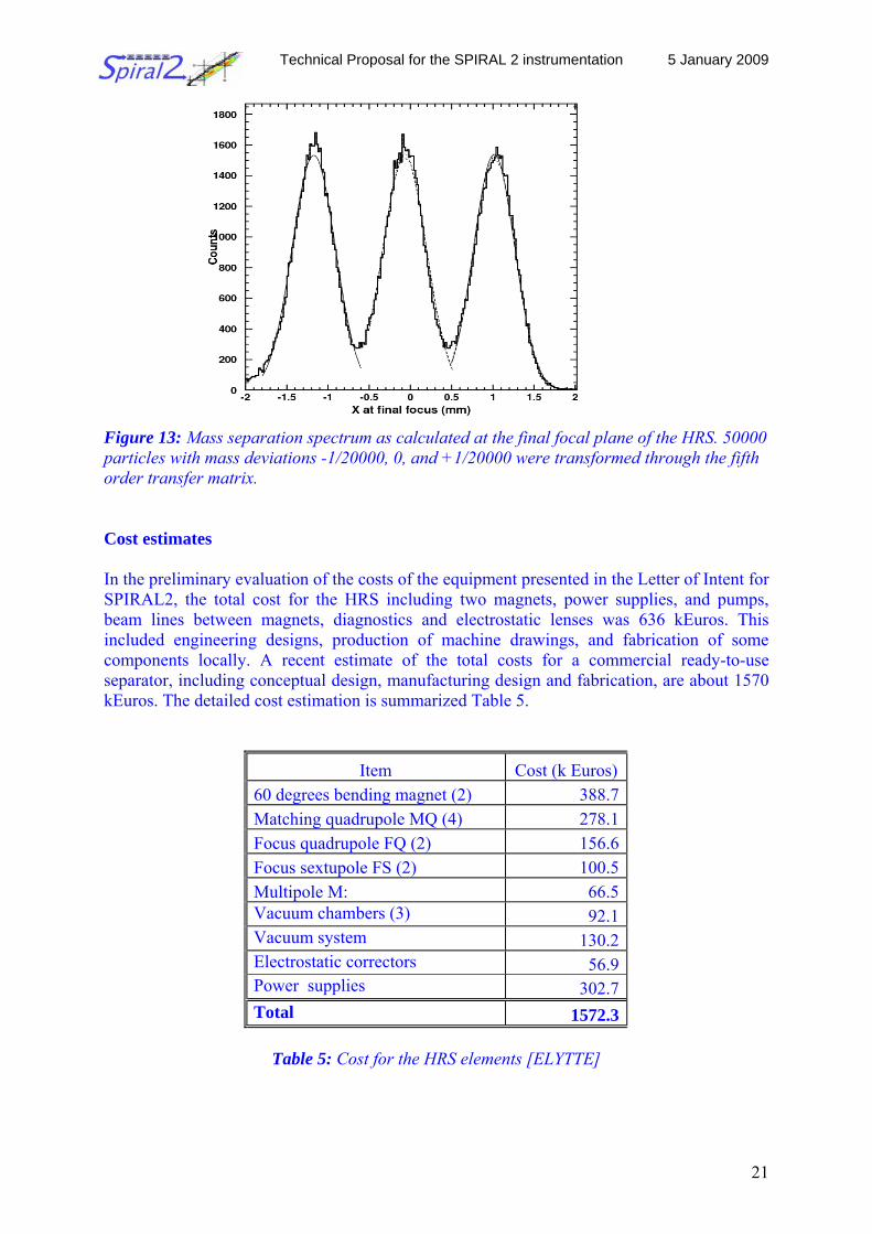
A Monte Carlo code was developed to obtain the mass distributions transformed through the calculated 5th order transfer matrix. Figure 13 shows a calculation of 50000 particles with mass deviations -1/20000, 0 and +1/20000. The initial phase space was assumed to be elliptic and Gaussian with FWHM values Δx = 1mm and Δa = 12mrad. The three well separated peaks correspond to the different masses.
Additionally, aberrations due to mechanical imperfections or misalignments were studied. Shifts in the dispersive x-direction induce a deformation in the x-a phase space, which produces a blur in the final mass separation. Details of all these studies are given in a report available on the DESIR web pages.
Beam quality:
A beam emittance of the order of <3 π mm mrad and an energy dispersion of about 1 eV are needed. These requirements will be fulfilled with the RFQ cooler and buncher of DESIR.
Technical Proposal for the SPIRAL 2 instrumentation 5 January 2009
21
Figure 13: Mass separation spectrum as calculated at the final focal plane of the HRS. 50000 particles with mass deviations -1/20000, 0, and +1/20000 were transformed through the fifth order transfer matrix. Cost estimates
In the preliminary evaluation of the costs of the equipment presented in the Letter of Intent for SPIRAL2, the total cost for the HRS including two magnets, power supplies, and pumps, beam lines between magnets, diagnostics and electrostatic lenses was 636 kEuros. This included engineering designs, production of machine drawings, and fabrication of some components locally. A recent estimate of the total costs for a commercial ready-to-use separator, including conceptual design, manufacturing design and fabrication, are about 1570 kEuros. The detailed cost estimation is summarized Table 5.
Item Cost (k Euros) 60 degrees bending magnet (2) 388.7 Matching quadrupole MQ (4) 278.1 Focus quadrupole FQ (2) 156.6 Focus sextupole FS (2) 100.5 Multipole M: 66.5 Vacuum chambers (3) 92.1 Vacuum system 130.2 Electrostatic correctors 56.9 Power supplies 302.7 Total 1572.3
Table 5: Cost for the HRS elements [ELYTTE]
Technical Proposal for the SPIRAL 2 instrumentation 5 January 2009
22
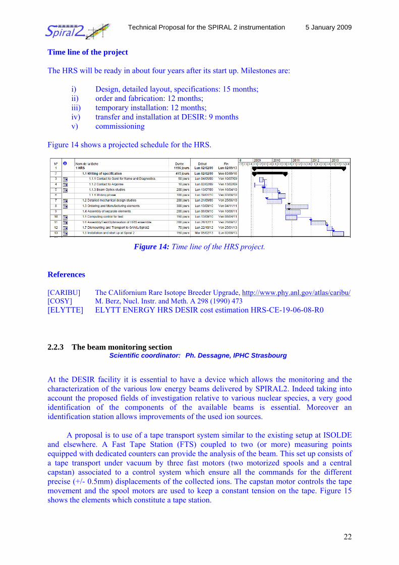
Time line of the project The HRS will be ready in about four years after its start up. Milestones are:
i) Design, detailed layout, specifications: 15 months; ii) order and fabrication: 12 months; iii) temporary installation: 12 months; iv) transfer and installation at DESIR: 9 months v) commissioning
Figure 14 shows a projected schedule for the HRS.
Figure 14: Time line of the HRS project. References [CARIBU] The CAlifornium Rare Isotope Breeder Upgrade, http://www.phy.anl.gov/atlas/caribu/ [COSY] M. Berz, Nucl. Instr. and Meth. A 298 (1990) 473 [ELYTTE] ELYTT ENERGY HRS DESIR cost estimation HRS-CE-19-06-08-R0 2.2.3 The beam monitoring section Scientific coordinator: Ph. Dessagne, IPHC Strasbourg At the DESIR facility it is essential to have a device which allows the monitoring and the characterization of the various low energy beams delivered by SPIRAL2. Indeed taking into account the proposed fields of investigation relative to various nuclear species, a very good identification of the components of the available beams is essential. Moreover an identification station allows improvements of the used ion sources.
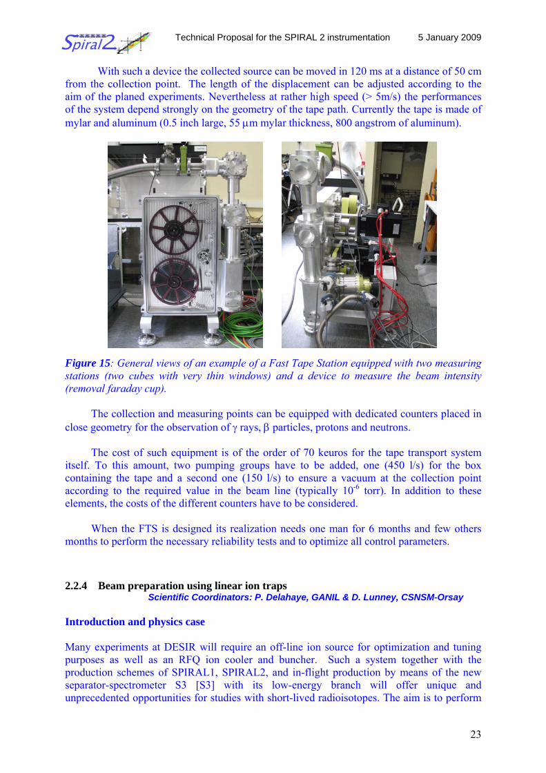
A proposal is to use of a tape transport system similar to the existing setup at ISOLDE and elsewhere. A Fast Tape Station (FTS) coupled to two (or more) measuring points equipped with dedicated counters can provide the analysis of the beam. This set up consists of a tape transport under vacuum by three fast motors (two motorized spools and a central capstan) associated to a control system which ensure all the commands for the different precise (+/- 0.5mm) displacements of the collected ions. The capstan motor controls the tape movement and the spool motors are used to keep a constant tension on the tape. Figure 15 shows the elements which constitute a tape station.
Technical Proposal for the SPIRAL 2 instrumentation 5 January 2009
23
With such a device the collected source can be moved in 120 ms at a distance of 50 cm from the collection point. The length of the displacement can be adjusted according to the aim of the planed experiments. Nevertheless at rather high speed (> 5m/s) the performances of the system depend strongly on the geometry of the tape path. Currently the tape is made of mylar and aluminum (0.5 inch large, 55 μm mylar thickness, 800 angstrom of aluminum).
Figure 15: General views of an example of a Fast Tape Station equipped with two measuring stations (two cubes with very thin windows) and a device to measure the beam intensity (removal faraday cup).
The collection and measuring points can be equipped with dedicated counters placed in
close geometry for the observation of γ rays, β particles, protons and neutrons.
The cost of such equipment is of the order of 70 keuros for the tape transport system itself. To this amount, two pumping groups have to be added, one (450 l/s) for the box containing the tape and a second one (150 l/s) to ensure a vacuum at the collection point according to the required value in the beam line (typically 10-6 torr). In addition to these elements, the costs of the different counters have to be considered.
When the FTS is designed its realization needs one man for 6 months and few others months to perform the necessary reliability tests and to optimize all control parameters. 2.2.4 Beam preparation using linear ion traps
Scientific Coordinators: P. Delahaye, GANIL & D. Lunney, CSNSM-Orsay Introduction and physics case Many experiments at DESIR will require an off-line ion source for optimization and tuning purposes as well as an RFQ ion cooler and buncher. Such a system together with the production schemes of SPIRAL1, SPIRAL2, and in-flight production by means of the new separator-spectrometer S3 [S3] with its low-energy branch will offer unique and unprecedented opportunities for studies with short-lived radioisotopes. The aim is to perform
Technical Proposal for the SPIRAL 2 instrumentation 5 January 2009
24
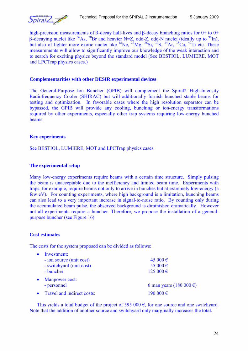
high-precision measurements of β-decay half-lives and β-decay branching ratios for 0+ to 0+ β-decaying nuclei like 66As, 70Br and heavier N=Z, odd-Z, odd-N nuclei (ideally up to 98In), but also of lighter more exotic nuclei like 18Ne, 22Mg, 26Si, 30S, 34Ar, 38Ca, 42Ti etc. These measurements will allow to significantly improve our knowledge of the weak interaction and to search for exciting physics beyond the standard model (See BESTIOL, LUMIERE, MOT and LPCTrap physics cases.) Complementarities with other DESIR experimental devices The General-Purpose Ion Buncher (GPIB) will complement the Spiral2 High-Intensity Radiofrequency Cooler (SHIRAC) but will additionally furnish bunched stable beams for testing and optimization. In favorable cases where the high resolution separator can be bypassed, the GPIB will provide any cooling, bunching or ion-energy transformations required by other experiments, especially other trap systems requiring low-energy bunched beams. Key experiments See BESTIOL, LUMIERE, MOT and LPCTrap physics cases. The experimental setup Many low-energy experiments require beams with a certain time structure. Simply pulsing the beam is unacceptable due to the inefficiency and limited beam time. Experiments with traps, for example, require beams not only to arrive in bunches but at extremely low-energy (a few eV). For counting experiments, where high background is a limitation, bunching beams can also lead to a very important increase in signal-to-noise ratio. By counting only during the accumulated beam pulse, the observed background is diminished dramatically. However not all experiments require a buncher. Therefore, we propose the installation of a general-purpose buncher (see Figure 16) Cost estimates The costs for the system proposed can be divided as follows:
• Investment: - ion source (unit cost) 45 000 € - switchyard (unit cost) 55 000 € - buncher 125 000 €
• Manpower cost: - personnel 6 man years (180 000 €)
• Travel and indirect costs: 190 000 €
This yields a total budget of the project of 595 000 €, for one source and one switchyard. Note that the addition of another source and switchyard only marginally increases the total.
Technical Proposal for the SPIRAL 2 instrumentation 5 January 2009
25
Schedule Task 1: simulation
The project will start with detailed simulations of the buncher system for the present application and beam optics calculations. Time and personpower: 12 months; 1 person-years
Task 2: Design and construction To avoid delays, we intend to purchase vacuum components and power supplies as soon as possible. At the same time, the design of the lenses and electrodes can start so that after about two years all parts will be available. Time and personpower: 24 months; 2 person-years
Task 3: Installation and commissioning
We count about twelve months to install the whole system for testing and optimising. Afterwards the system will be transferred to the DESIR facility of GANIL for installation followed by first off-line experiments at DESIR. Time and personpower: 18 months; 3 person-years
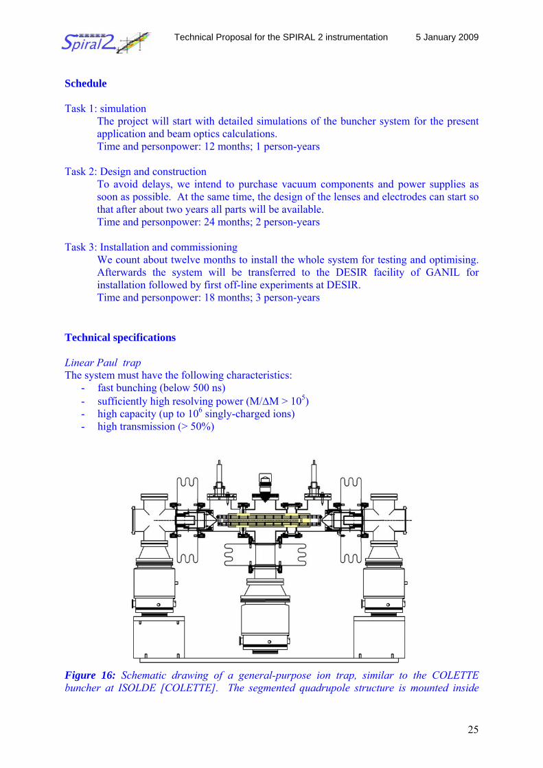
Technical specifications Linear Paul trap The system must have the following characteristics:
- fast bunching (below 500 ns) - sufficiently high resolving power (M/ΔM > 105) - high capacity (up to 106 singly-charged ions) - high transmission (> 50%)
Figure 16: Schematic drawing of a general-purpose ion trap, similar to the COLETTE buncher at ISOLDE [COLETTE]. The segmented quadrupole structure is mounted inside
Technical Proposal for the SPIRAL 2 instrumentation 5 January 2009
26
standard ISO-100 KF vacuum components and insulated from the turbomolecular pumping ports. The overall length is about one meter.
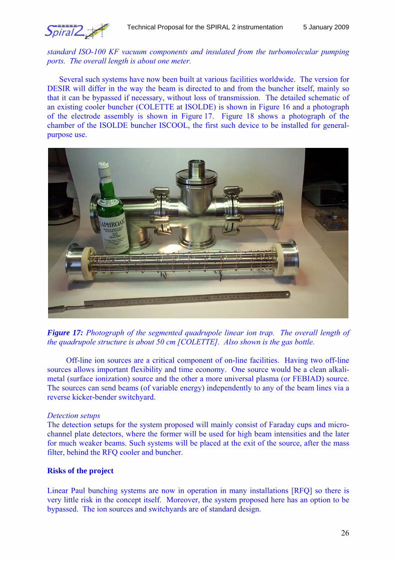
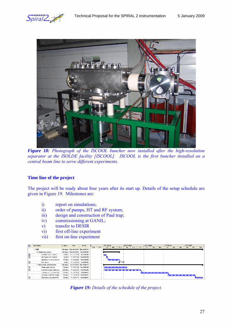
Several such systems have now been built at various facilities worldwide. The version for DESIR will differ in the way the beam is directed to and from the buncher itself, mainly so that it can be bypassed if necessary, without loss of transmission. The detailed schematic of an existing cooler buncher (COLETTE at ISOLDE) is shown in Figure 16 and a photograph of the electrode assembly is shown in Figure 17. Figure 18 shows a photograph of the chamber of the ISOLDE buncher ISCOOL, the first such device to be installed for general-purpose use.
Figure 17: Photograph of the segmented quadrupole linear ion trap. The overall length of the quadrupole structure is about 50 cm [COLETTE]. Also shown is the gas bottle.
Off-line ion sources are a critical component of on-line facilities. Having two off-line sources allows important flexibility and time economy. One source would be a clean alkali-metal (surface ionization) source and the other a more universal plasma (or FEBIAD) source. The sources can send beams (of variable energy) independently to any of the beam lines via a reverse kicker-bender switchyard. Detection setups The detection setups for the system proposed will mainly consist of Faraday cups and micro-channel plate detectors, where the former will be used for high beam intensities and the later for much weaker beams. Such systems will be placed at the exit of the source, after the mass filter, behind the RFQ cooler and buncher. Risks of the project Linear Paul bunching systems are now in operation in many installations [RFQ] so there is very little risk in the concept itself. Moreover, the system proposed here has an option to be bypassed. The ion sources and switchyards are of standard design.
Technical Proposal for the SPIRAL 2 instrumentation 5 January 2009
27
Figure 18: Photograph of the ISCOOL buncher now installed after the high-resolution separator at the ISOLDE facility [ISCOOL]. ISCOOL is the first buncher installed on a central beam line to serve different experiments. Time line of the project The project will be ready about four years after its start up. Details of the setup schedule are given in Figure 19. Milestones are:
i) report on simulations; ii) order of pumps, HT and RF system; iii) design and construction of Paul trap; iv) commissioning at GANIL; v) transfer to DESIR vi) first off-line experiment vii) first on-line experiment
Figure 19: Details of the schedule of the project.
Technical Proposal for the SPIRAL 2 instrumentation 5 January 2009
28
Beam requirements Off-line tests: The GPIB will be part of the off-line facility. Beam quality: The beam acceptance is of the order of 80 π mm mrad and almost any energy dispersion can be accommodated. The output of the buncher is of the order of 5 π mm mrad at 50 keV with an energy spread of less than 1 eV. Beam intensities: To perform the experiments described above, minimum beam intensities of the ions of interest of about 100 pps are required. A maximum of a few nA should not be exceeded. References [DESIR] http://www.cenbg.in2p3.fr/desir/IMG/pdf/DESIR_LOI_SHORT.pdf [S3] http://www-dapnia.cea.fr/Phocea/Vie_des_labos/Ast/ast_technique.php?id_ast=943 [RFQ] http://en.wikipedia.org/wiki/RFQ_Beam_Coolers [COLETTE] D. Lunney et al., Nucl. Instrum. Meth. A (2008) doi: 10.1016/j.nima.2008.09.050 [ISCOOL] H. Frånberg et al., Nucl. Instrum. Meth. B 266 (2008) 4502 2.2.5 The LUMIERE facility: Light Utilization for Measurements and Ionization of
Exotic Radioactive Elements Scientific coordinators: F. Le Blanc, IPN Orsay, G. Neyens, Leuven, P. Campbell, Manchester
Introduction and physics case Atomic physics and optical techniques have played an important role to study the behaviour of nuclear matter at low excitation energy. Nuclear properties are deduced through the observation of the magnetic and electrostatic hyperfine structure in optical spectra, as well as through the influence of the changes in nuclear charge radii on the isotope shifts between different isotopes of a given element. For 30 years, lasers have been used at accelerators to measure these quantities and the best example is the observation of the sudden change in the nuclear charge radius in the mercury isotopes showing a large shape transition at mid-shell (N=108). Today with different techniques such as collinear laser spectroscopy and ß-NMR (Nuclear Magnetic Resonance) applied to optically polarized radioactive beams, laser spectroscopy still continues to deliver key information on properties of nuclear ground states and long-lived isomers with the measurement of the spin, the magnetic moment, the quadrupole moment and the change in the mean square charge radius between two isotopes. These experimental data are highly accurate and the nuclear parameters can be extracted model-independently which constitutes a stringent test for nuclear theory. To study the hyperfine anomaly or to have access to higher order nuclear moments (octupole and hexadecapole) one can use ion traps. Once again, the combination of the laser
Technical Proposal for the SPIRAL 2 instrumentation 5 January 2009
29
optical pumping and the radiofrequency scan inside a hyperfine multiplet gives a precision of 10-9 on the magnetic hyperfine constant, allowing to reach the forth order in nuclear deformation. At SPIRAL2 and its low-energy beam facility DESIR, the aim is to build three kinds of setups to try to cover the whole nuclear chart. A ß-NMR setup will be suitable to study precisely the moments of key cases and, in combination with collinear hyperfine spectroscopy, to get unambiguous spin assignments. With a collinear spectroscopy setup, we will have the possibility to study series of isotopes in the intermediate and heavy mass regions. For the heavy elements, a double laser + RF spectroscopy in a Paul trap will be used to study the hyperfine anomaly and higher-order moments up to very high precision. The new collinear laser spectroscopy setup is currently being built on-line at ALTO in Orsay. After intense testing and optimizing, the whole setup will be re-installed at DESIR. Like any other device, this kind of setup requires an off-line ion source for optimization and tuning purposes. This off-line source, which will be useful also for others experiments, should be installed before an RFQ ion cooler and buncher which is a key instrument to perform successful collinear laser spectroscopy measurements on exotic isotopes. Such a system together with the production schemes of SPIRAL2 and in-flight production of refractory elements by means of the new separator-spectrometer S3 with its low-energy branch will offer unique and unprecedented opportunities for studies with short-lived radioisotopes. Any nucleus of interest will be accessible for the proposed setup as long as its production cross-section is high enough to deliver at least 200 isotopes per second in the collinear and ß-NMR beam line. Key experiments Neutron-rich isotopes in the fission peaks will be available from the SPIRAL2 fission source coupled to a high-resolution mass separator and RFQ, from which low-energy beams are then sent into the DESIR setups. Low-energy beams of refractory elements, of proton-rich isotopes and of heavy elements (trans-actinides) will be produced using fusion-evaporation reactions with the very intense stable beams from the SPIRAL2-LINAG. The reaction products will be separated from the primary beam with the S3 super separator spectrometer, stopped in a gas cell and re-ionized to be sent to the DESIR setups. Thus a very wide range of elements and isotopes will be accessible for measurements.
- Collinear spectroscopy: - Extending charge radii, moments and spin measurements of exotic
isotopes around 78Ni and 132Sn. - Charge radius changes and moments of exotic Rb (above N=90), Sr (above
N=100) an Yb (above N=177). - Hyperfine structure and charge radii of trans-actinides (very few data are
available now). - ß-NMR: - Ground state spin of N=49 and N=51 isotones with even Z
- Microwave double resonance in Paul trap (with S3 beams):
Technical Proposal for the SPIRAL 2 instrumentation 5 January 2009
30
- Charge radius of 100Sn - Quadrupole and magnetic moments in the transfermium isotopes
The experimental setup The LUMIERE project comprises three experimental setups with two beam-lines: one for the collinear laser spectroscopy and the ß-NMR experiments and the second one at the Paul trap line for the radiofrequency spectroscopy.
The technique of collinear laser spectroscopy is mainly used for its versatility and the
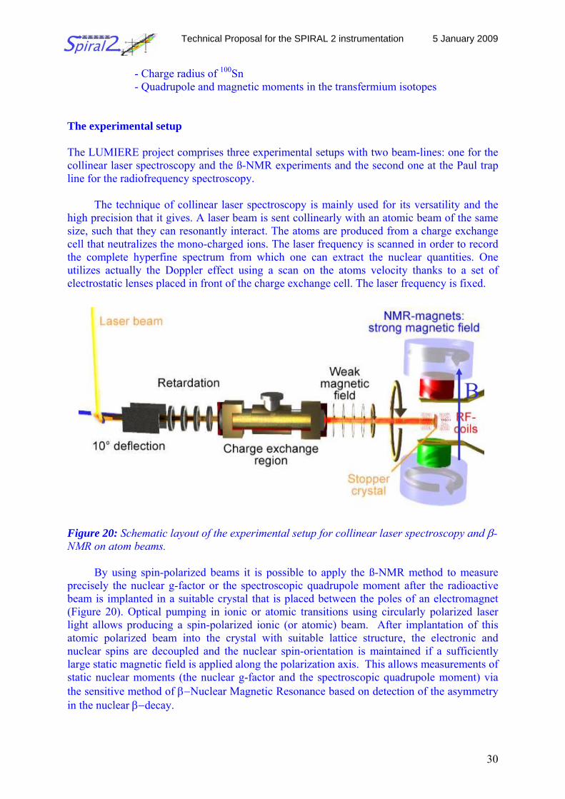
high precision that it gives. A laser beam is sent collinearly with an atomic beam of the same size, such that they can resonantly interact. The atoms are produced from a charge exchange cell that neutralizes the mono-charged ions. The laser frequency is scanned in order to record the complete hyperfine spectrum from which one can extract the nuclear quantities. One utilizes actually the Doppler effect using a scan on the atoms velocity thanks to a set of electrostatic lenses placed in front of the charge exchange cell. The laser frequency is fixed. Figure 20: Schematic layout of the experimental setup for collinear laser spectroscopy and β-NMR on atom beams.
By using spin-polarized beams it is possible to apply the ß-NMR method to measure precisely the nuclear g-factor or the spectroscopic quadrupole moment after the radioactive beam is implanted in a suitable crystal that is placed between the poles of an electromagnet (Figure 20). Optical pumping in ionic or atomic transitions using circularly polarized laser light allows producing a spin-polarized ionic (or atomic) beam. After implantation of this atomic polarized beam into the crystal with suitable lattice structure, the electronic and nuclear spins are decoupled and the nuclear spin-orientation is maintained if a sufficiently large static magnetic field is applied along the polarization axis. This allows measurements of static nuclear moments (the nuclear g-factor and the spectroscopic quadrupole moment) via the sensitive method of β−Nuclear Magnetic Resonance based on detection of the asymmetry in the nuclear β−decay.
B
Technical Proposal for the SPIRAL 2 instrumentation 5 January 2009
31
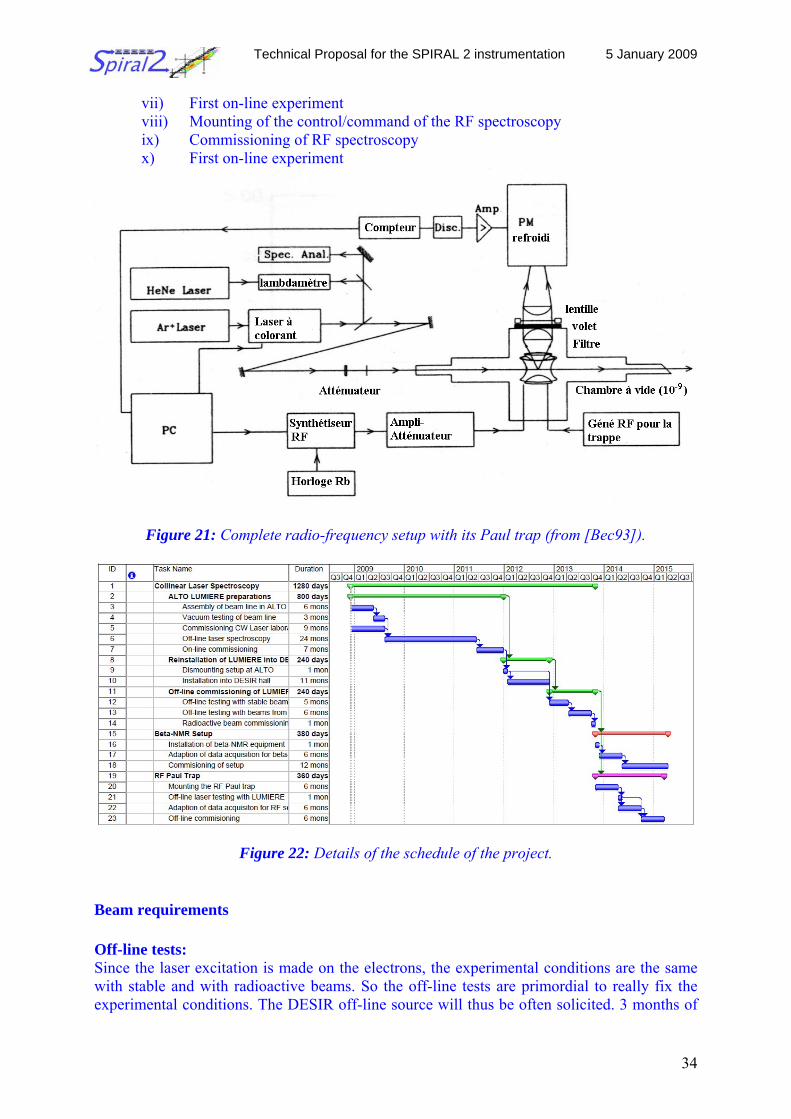
For radiofrequency spectroscopy, one proposes to use the Paul trap situated on the other side of the central line (see Figure 6). The trapped ions will be optically pumped on a hyperfine level with a single mode laser beam. Then, a radiofrequency scan is made to generate a radiofrequency spectrum of the hyperfine multiplet. The center of gravity gives access to the nuclear moment at very high precision.
The method has been pioneered off-line in Mainz using ISOLDE sample of Europium [Bec93]. The precision reached was 10-9 on the magnetic moment and 10-6 on the quadrupole moment with some thousand ions in the trap. Cost estimates For the physics, the laser installation requires an equipped laser room of about 20 m2 generally on a mezzanine, with high vibrational stabilization. The lasers for the 3 LUMIERE physics cases can be a high- resolution dye laser (Ring type) pumped by a 20 W argon laser. In the experimental hall, two lines have to be installed: one for the laser spectroscopy / ß- NMR and another with high vacuum (10-9) for the Paul trap. • Laser room with infrastructure 150 kEuros • Two lasers (dye+Ar) 180 kEuros • Collinear spectroscopy installation: charge exchange cell, beam line (electrostatic elements, diagnostic, power supply), vacuum, electronics, detection 170 kEuros • ß-NMR setup: RF, cooling system, telescope, vacuum, magnet 160 kEuros • Paul trap setup: Paul trap, RF, beam line (diagnostic, retardation lens), cryogenic pumping 150 kEuros • 20% overhead 162 kEuros The total cost for the LUMIERE facility is therefore 972 kEuros. Schedule The LUMIERE project has to be considered in three parts that will be constructed one after the other: the collinear spectroscopy part, the ß-NMR part and the Paul trap part. The schedule begins from now since the collinear spectroscopy part is currently being mounted at Orsay on line with ALTO. Part 1: Collinear laser spectroscopy
Task 1: Assembling and testing the collinear laser spectroscopy setup. Practically all the elements are available at Orsay. One has to mount two parts: the atom beam line and the laser setup. Finally, a control/command acquisition system has to be implemented. The beam line comprises basically a set of three electrostatic lenses, a charge exchange cell and a large light guide for photon detection. To get a very good frequency resolution and to have access to a large set of wavelengths, we will use a CW single Ring dye laser pumped by a 20
Technical Proposal for the SPIRAL 2 instrumentation 5 January 2009
32
W argon laser. For the control/command system one has to command the frequency scan using the electrostatic lenses and to control the acquisition of the hyperfine photon triggered with the ion bunches of the DESIR cooler/buncher GPIB (section 2.2.4) The project has started now and will take 3 years in Orsay with the operation of a complete collinear laser spectroscopy setup by 2012. Time and manpower: 2 man year, 36 months
Task 2: Reinstalling the laser spectroscopy at SPIRAL2. All the setup will be dismounted in Orsay and rebuilt in the DESIR hall as soon as it is accessible. Time and manpower: 2 man years, 12 months
Task 3: Installation and commissioning
The commissioning will take also one year. The setup will be first tested with stable beam without cooler, then, with the cooler and finally with a radioactive beam. Time and manpower: 3 man years, 12 months
Part 2: ß-NMR setup
The β-NMR setup will be installed at the end of the collinear laser spectroscopy line, in order to use the optical pumping with polarized laser light to produce polarized radioactive beams for precision measurements of nuclear moments. Installation will start once the collinear beam line is operational, estimated about 2 years after the building is accessible.
Task 1: installation of the β-NMR magnet and related equipment Time and manpower: 2 man-months, 1 month
Task 2: adapt the laser data acquisition system for combined laser and β-NMR measurements Time and manpower: 1 man-year, 6 months Task3: commissioning of the setup Time and manpower: 2 man-year, 1 year
Part 3: RF trap
The LPC Paul trap can be used for RF laser spectroscopy. One has to collect mono-charged ions (some 104). A single mode laser beam is sent inside the trap to optically pump the atomic Zeeman ground state. One then performs a RF scan in order to detect all the Zeeman transition while the laser beam is continuously present to pump the ground level. One detects de-excitation photons proportional to the Zeeman line intensity.
Task 1: mounting the radiofrequency setup around the Paul trap.
Time and manpower: 2 man years, 6 months
Task 2: The laser setup used will be the same as for collinear spectroscopy.
Technical Proposal for the SPIRAL 2 instrumentation 5 January 2009
33
Time and manpower: 1 man year, 1 month
Task 3: The acquisition system will also be the same as for laser spectroscopy but it has to be quite adapted: scanning of the RF instead of the electrostatic lenses.
Time and manpower: 1 man year, 6 months Task 4: Commissioning of the apparatus with off-line beam. Time and manpower: 2 man years, 6 months. Technical specifications Collinear laser spectroscopy and ß-NMR The system has to have the following characteristics:
- fast separation (below 100 ms) - sufficiently high resolving power (M/ΔM > 105) - high capacity (up to 108/s singly-charged ions) - high transmission (> 80%).
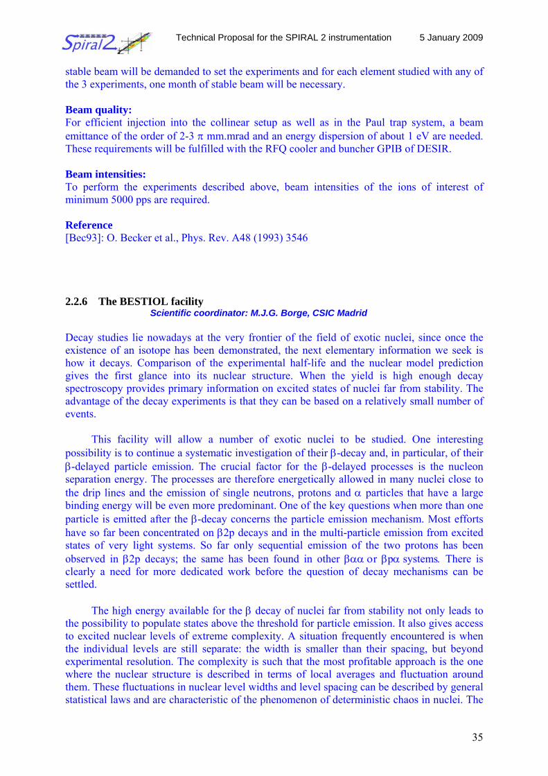
Radiofrequency spectroscopy The system has to have the same characteristics as above with the introduction of 105 ions at maximum in the trap. Detection setups Collinear spectroscopy: The detection setup consists in a water-cooled photomultiplier. Just in front of it, a small ion deflector is placed and, behind, a MCP detector. This is to measure the parasitic ions crossing the charge exchange cell to have an idea of the background. ß-NMR: The detection consists in measuring the radioactivity electron/positron at the Larmor frequency. So two scintillators are placed at 0 and 180 cm of the interaction crystal. For the Paul trap RF spectroscopy, the detection setup consists also in a photomultiplier placed above the trap (see Figure 21). Risks of the project The only risks are associated with the Laser light. So the laser beam has to be sent inside a tube from the laser room to the LUMIERE setup. Time line of the project The project will be ready about four years after its start up. Details of the setup schedule are given in Figure 22. Milestones are:
i) Report on stable beam collinear spectroscopy at Orsay ii) Commissioning of collinear laser spectroscopy at Orsay on a radioactive tin
beam iii) Transfer and mounting at DESIR; iv) Mounting of the ß-NMR part v) Commissioning of laser spectroscopy vi) Commissioning of ß-NMR
Technical Proposal for the SPIRAL 2 instrumentation 5 January 2009
34
vii) First on-line experiment viii) Mounting of the control/command of the RF spectroscopy ix) Commissioning of RF spectroscopy x) First on-line experiment
Figure 21: Complete radio-frequency setup with its Paul trap (from [Bec93]).
Figure 22: Details of the schedule of the project. Beam requirements Off-line tests: Since the laser excitation is made on the electrons, the experimental conditions are the same with stable and with radioactive beams. So the off-line tests are primordial to really fix the experimental conditions. The DESIR off-line source will thus be often solicited. 3 months of
Technical Proposal for the SPIRAL 2 instrumentation 5 January 2009
35
stable beam will be demanded to set the experiments and for each element studied with any of the 3 experiments, one month of stable beam will be necessary. Beam quality: For efficient injection into the collinear setup as well as in the Paul trap system, a beam emittance of the order of 2-3 π mm.mrad and an energy dispersion of about 1 eV are needed. These requirements will be fulfilled with the RFQ cooler and buncher GPIB of DESIR. Beam intensities: To perform the experiments described above, beam intensities of the ions of interest of minimum 5000 pps are required. Reference [Bec93]: O. Becker et al., Phys. Rev. A48 (1993) 3546 2.2.6 The BESTIOL facility Scientific coordinator: M.J.G. Borge, CSIC Madrid
Decay studies lie nowadays at the very frontier of the field of exotic nuclei, since once the existence of an isotope has been demonstrated, the next elementary information we seek is how it decays. Comparison of the experimental half-life and the nuclear model prediction gives the first glance into its nuclear structure. When the yield is high enough decay spectroscopy provides primary information on excited states of nuclei far from stability. The advantage of the decay experiments is that they can be based on a relatively small number of events.
This facility will allow a number of exotic nuclei to be studied. One interesting possibility is to continue a systematic investigation of their β-decay and, in particular, of their β-delayed particle emission. The crucial factor for the β-delayed processes is the nucleon separation energy. The processes are therefore energetically allowed in many nuclei close to the drip lines and the emission of single neutrons, protons and α particles that have a large binding energy will be even more predominant. One of the key questions when more than one particle is emitted after the β-decay concerns the particle emission mechanism. Most efforts have so far been concentrated on β2p decays and in the multi-particle emission from excited states of very light systems. So far only sequential emission of the two protons has been observed in β2p decays; the same has been found in other βαα οr βpα systems. There is clearly a need for more dedicated work before the question of decay mechanisms can be settled.
The high energy available for the β decay of nuclei far from stability not only leads to the possibility to populate states above the threshold for particle emission. It also gives access to excited nuclear levels of extreme complexity. A situation frequently encountered is when the individual levels are still separate: the width is smaller than their spacing, but beyond experimental resolution. The complexity is such that the most profitable approach is the one where the nuclear structure is described in terms of local averages and fluctuation around them. These fluctuations in nuclear level widths and level spacing can be described by general statistical laws and are characteristic of the phenomenon of deterministic chaos in nuclei. The
Technical Proposal for the SPIRAL 2 instrumentation 5 January 2009
36
fluctuations in the spectrum provide an interesting method to determine level densities in exotic nuclei of great astrophysical interest.
Nuclear species with an equal number of neutrons and protons are very interesting. Due to the repulsive Coulomb force of the protons, the N=Z line departs from stability above mass 40, developing along the particle stability border up to 100Sn. Neutrons and protons occupy the same orbital, so questions related to the properties of T=0 (np interaction) and T=1 (pp or nn interaction) states can be cleared up.
For nuclei with N≈Z and A≈70-80 this fact together with the low single-particle level
density leads to rapid changes in deformation with the addition or subtraction of only a few nucleons. Mean field calculations predict the GT decay mode to be sensitive to nuclear ground-state deformation. The calculations give for even-even nuclei in the A=70 region strong differences in the total intensity and energy distribution of the GT strength depending of the shape of the parent nucleus. In fact a strong sudden shape transition between oblate and prolate deformation is predicted to happen between N=Z=36 and N=Z=38. The method proposed here is an accurate measurement of BGT as a function of the excitation energy in the daughter nucleus by means of total absorption spectroscopy.
For our understanding of the r-process nucleosynthesis of heavy elements in supernova
explosions we need to know the β-decay half life, the neutron branching ratios and the neutron (or two-neutron) separation energy of these nuclei.
2.2.6.1 A total absorption spectroscopy setup for β-decay studies Scientific coordinator: Jose L. Tain, IFIC-Valencia
Introduction and physics case Beta decay is by far the most common form of radioactivity for nuclei away from the stability valley. Therefore the knowledge of the β-decay properties contributes decisively to our understanding of nuclear phenomena. In particular the accurate measurement of the distribution of decay probabilities over the entire accessible energy window reveals fundamental aspects of the structure of atomic nuclei and provides essential data for the fields of fundamental physics, astrophysics, nuclear technology and neutrino physics.
The vast majority of the information that we have about the β-intensity distribution is coming from the level schemes obtained in high resolution experiments with germanium detectors. It is known [HAR77] that this technique suffers from a systematic error (the Pandemonium effect) that tends to displace the β intensity towards low excitation energies. This error can be dramatic for nuclei far from stability with large Q-values and/or level densities, and it is related to the low detection probability of high-lying high-energy gamma-ray transitions. The total absorption spectroscopy in β-decay studies was introduced to overcome this limitation since it is based on the detection of the full cascade branch using high efficiency close-to-4π scintillation detectors [TAI07]. We propose to install at DESIR a new total absorption spectrometer in order to perform accurate measurements of the β−strength distribution on relevant isotopes.
Technical Proposal for the SPIRAL 2 instrumentation 5 January 2009
37
Due to the simplicity of the allowed decay operator, where the transformed nucleon remains in its orbit changing at most the spin orientation, the β strength reflects sensitively the structure of the available orbitals for the transition. This explains why the bulk of the allowed strength in β- decay lies outside the β-decay window, since the empty proton orbitals are pushed up by the Coulomb interaction, and only the tail of the distribution is observed. However, and contrary to the common assumption, there is ample evidence for a rich structure in the accessible strength distribution which provides a sensitive test of nuclear model calculations. This will be particularly important for calculations which aim to predict the β-decay half lives for nuclei lying on the r-process path not accessible to experimental determination. The study of the β-strength distribution in neutron rich medium and medium-heavy nuclei approaching the waiting-point nuclei will help to improve the r-process nucleosynthesis abundance calculations. Additionally the study of nuclei in the vicinity of 78Ni and 132Sn in order to search for the existence of high lying weak decay branches will provide a clearer picture of the nuclear structure around closed shells far from the stability. These nuclei will be available at SPIRAL2 with the needed abundances from uranium fission.
In the case of EC/β+ decays it is possible to find regions of the nuclear chart where a significant fraction of the strength is located within the decay window as is the case for nuclei with N~Z, or even the bulk of the strength as is the case of nuclei around 100Sn and 146Gd. The study of nuclei in these regions will shed light on isospin effects, the shell structure of magic nuclei, the interplay of single particle and collective motions, and the effect of the nuclear shape. At SPIRAL2 the production of such nuclei will be possible using fusion-evaporation reactions and the S3 separator-spectrometer. This offers also the possibility to contribute decisively to the unitarity test of the Cabibbo-Kobayashi-Maskawa matrix via the precise superallowed decay probabilities of odd-odd N=Z nuclei. As has been pointed out [HAR02], the extension of the test to the heavier isotopes (A≥62) requires the determination of the contribution to the decay of high-lying very weak decay branches for which the total absorption spectrometer is ideally suited.
The accurate determination of the β-decay intensity distributions of the fission products which are generated in nuclear reactors has important consequences for the calculation of the reactor heat after shutdown, with implications in the spent fuel discharge and handling procedures, and at the same time for the calculation of the reactor neutrino spectra, with implications in the analysis of neutrino oscillation experiments. Some key isotopes are suspected to suffer from large systematic errors and their measurement will represent and important contribution to these fields. Complementarily with other DESIR experimental devices The total absorption spectrometer can and will be used at the general purpose beam line of the DESIR facility. However the availability of the double Penning trap system (which allows isotopic purification of the samples) will boost the quality of the measurements, since spectrum contamination is the major source of systematic error in this technique. The use of the TAS behind the trap assisted spectroscopy setup should be foreseen. Key experiments Complete β-strength determination of nuclei with N=82 below 132Sn which constitute important waiting-points for r-process calculations in order to understand the shell structure in this region and its influence on theoretical half life estimations.
Technical Proposal for the SPIRAL 2 instrumentation 5 January 2009
38
Detailed β-strength determination of odd-odd N=Z nuclei heavier than A=62 in order to
look for Gamow-Teller high lying competitor decay branches to the 0+ → 0+ superallowed decay. The aim is to improve the accuracy of the tests of the CVC hypothesis. The experimental setup The total absorption spectrometer will register the energy deposited by the β-delayed γ-ray cascades and eventually the particle penetration. The β-intensity distribution is obtained through deconvolution of the measured spectra using the spectrometer response to the decay obtained from Monte Carlo simulations and average gamma-ray cascade properties. The segmentation of the spectrometer allows constraining the multiplicity and energy distribution of the cascades. A limited statistics of the spectrum in particular close to the end point (due to the phase space factor) affects the quality of the result. Previous experience shows that, in general, 105 counts in the spectrum is an acceptable value. Higher statistics will be required for more demanding measurements
The major source of systematic error in this technique is the spectrum contamination. Ambient background is reduced using radiation shielding around the spectrometer, but anyhow imposes a minimum on the measurable activity in the ungated spectrum. Background free spectra can be obtained tagging on the emitted electron/positron using a β detector (silicon or plastic scintillation detector) but this reduces strongly the efficiency close to the Qβ value due to the electronic threshold. In the case of EC decay, tagging on the daughter X-rays provides background free spectra and additionally isotopic selection. In the case of β-delayed neutron emitters, the neutrons are a source of contamination though inelastic and capture reactions in the detector. The good timing resolution of the spectrometer can be used to discriminate their larger flight time.
In general, the isotopic selection of the mass separated beam is achieved on the basis of half-life discrimination using appropriate collection-measuring time cycles for the isotope of interest and the possible contaminants (which is at least the decay daughter activity). The use of element selective ion sources is essential in the cases where half life differences are small or the contaminant proportion is very large.
The availability of the double Penning trap system at DESIR which can provide isotopic separation through extreme mass resolution represents a definitive improvement of the technique as it has shown recently through the TAS experiments performed at Jyväskylä [ALG07].
This proposal is based on the use of an already existing Surrey-Valencia total absorption spectrometer which can be transported an installed at DESIR for the specific measuring campaigns. Additionally there is also the possibility that the TAS which is being develop for the DESPEC experiment, could be used at DESIR when not in use at FAIR. Cost estimates The costs for the system are based on the Surrey-Valencia BaF2 TAS and can be divided as follows:
Technical Proposal for the SPIRAL 2 instrumentation 5 January 2009
39
• Investment: - Total absorption spectrometer: 185000 € - Ancillary detectors: - X-ray detector: 15000 € - Beta detector: 3000 € - Electronics: 55000 € - Data acquisition system: 52000 € - Lead shielding and assembly support: 15000 € - Tape transport system and vacuum beam pipe: 100000 € TOTAL: 425000 € • Manpower cost: - 1 person-year 40000 € • Travel and running costs: 15000 €
From the investment costs a large fraction (295000 € or 70%), corresponding to the TAS, the electronics and the DACQ, is already covered by Spanish and UK national grants. Schedule The spectrometer, the corresponding electronics and the data acquisition system are ready. The first in-beam tests will be performed at IGISOL-JYFL using the Penning trap as an isotopic purification filter during 2009.
The supporting table which allows alignment of the spectrometer to the beam-pipe and includes a sliding system to allow the easy access to the beam pipe end-cap is under design and will be ready during 2009. Remaining tasks: Tape transport system design and construction A fast tape transport system with the capability for implantation at the center of the spectrometer should be designed and constructed. Time and manpower: 18 months, 1person-year Technical specifications The Valencia-Surrey TAS is a 12-fold segmented spectrometer of cylindrical geometry with a longitudinal hole for the positioning of samples and ancillary detectors. The 6 BaF2 crystals on each half are viewed by 3” quartz window photomultipliers (Figure 23). The total scintillation material length and the external diameter are 25 cm. The length of the detector assembly including PMT is 76 cm and the diameter is 32.5 cm. The diameter of the inner hole is 5 cm. The total weight is 80 kg.
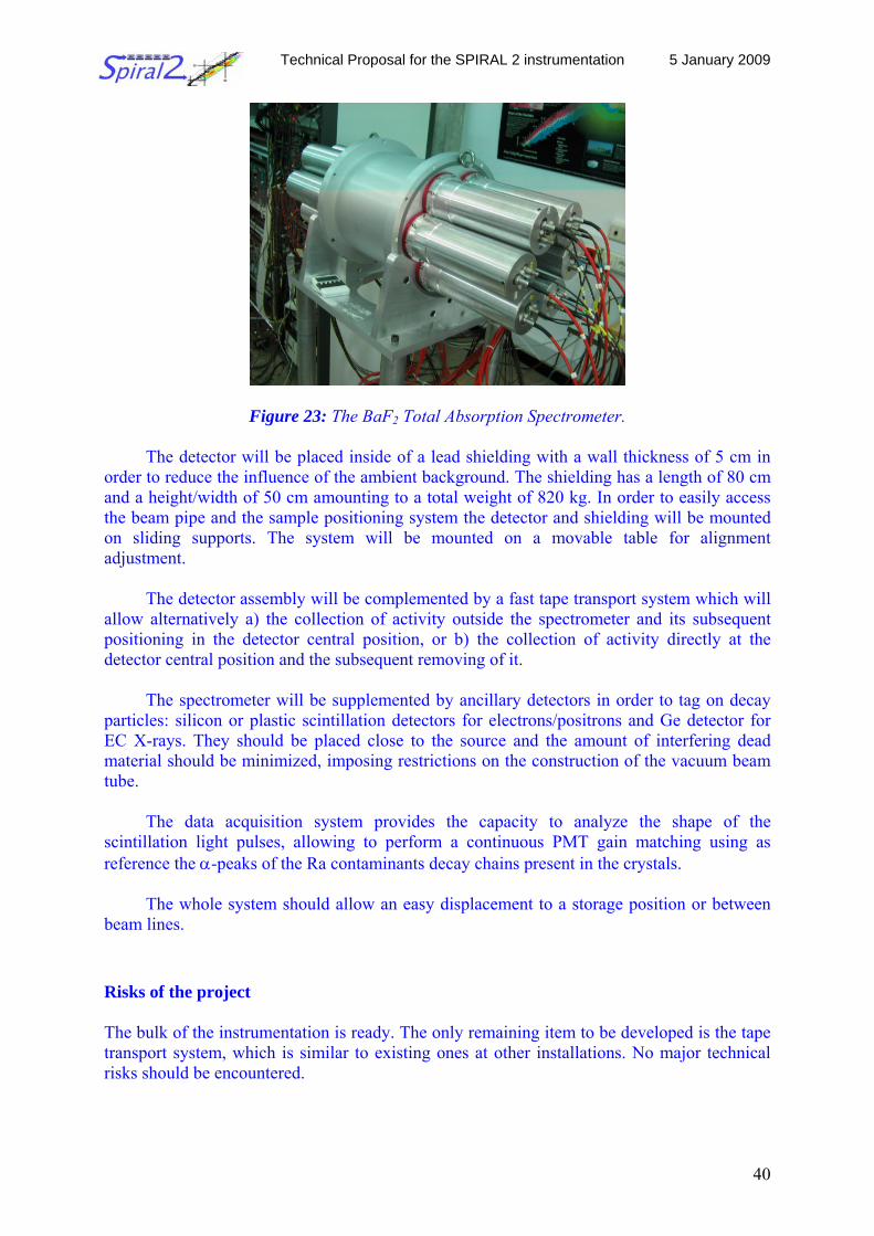
Technical Proposal for the SPIRAL 2 instrumentation 5 January 2009
40
Figure 23: The BaF2 Total Absorption Spectrometer.
The detector will be placed inside of a lead shielding with a wall thickness of 5 cm in order to reduce the influence of the ambient background. The shielding has a length of 80 cm and a height/width of 50 cm amounting to a total weight of 820 kg. In order to easily access the beam pipe and the sample positioning system the detector and shielding will be mounted on sliding supports. The system will be mounted on a movable table for alignment adjustment.
The detector assembly will be complemented by a fast tape transport system which will allow alternatively a) the collection of activity outside the spectrometer and its subsequent positioning in the detector central position, or b) the collection of activity directly at the detector central position and the subsequent removing of it.
The spectrometer will be supplemented by ancillary detectors in order to tag on decay particles: silicon or plastic scintillation detectors for electrons/positrons and Ge detector for EC X-rays. They should be placed close to the source and the amount of interfering dead material should be minimized, imposing restrictions on the construction of the vacuum beam tube.
The data acquisition system provides the capacity to analyze the shape of the scintillation light pulses, allowing to perform a continuous PMT gain matching using as reference the α-peaks of the Ra contaminants decay chains present in the crystals.
The whole system should allow an easy displacement to a storage position or between
beam lines. Risks of the project The bulk of the instrumentation is ready. The only remaining item to be developed is the tape transport system, which is similar to existing ones at other installations. No major technical risks should be encountered.
Technical Proposal for the SPIRAL 2 instrumentation 5 January 2009
41
Time line of the project The total absorption spectrometer is ready. The development of the tape station requires 18 months, and should be started to be in time with the completion of the facility. The general integration of the system and the first off-beam and in-beam tests will require 2 months. Beam requirements Beam quality: The emittance should be such as to allow an efficient beam collimation down to few millimeters for direct implantation on the tape system at the central position of the spectrometer, avoiding contamination of the beam vacuum tube parts in the proximity of the spectrometer. Beam intensity: In order to perform experiments acquiring the necessary statistics within reasonable time limits, will require beam intensities of 103 s-1 for ungated measurements, 102 s-1 for X-ray gated measurements or 10 s-1 for β-gated measurements. On the other hand, in order to prevent excessive electronic pulse pile-up and gain shifting which degrade the spectrum, intensities should be limited to less than 2×10⁴ s-1. References [HAR77] J. C. Hardy et al., Phys. Lett. 71B (1977) 307. [TAI07] http://nd2007.edpsciences.org/articles/ndata/pdf/2007/01/ndata07304.pdf [HAR02] J. C. Hardy et al., Phys. Rev. Lett. 88 (2002) 252501-1. [ALG07] http://nd2007.edpsciences.org/articles/ndata/pdf/2007/01/ndata07707.pdf 2.2.6.2 The double Penning trap setup
Scientific coordinator: B. Blank, CEN Bordeaux-Gradignan Introduction and physics case Our present knowledge of the fundamental interactions is summarized in the so-called standard model. High-precision measurements in particle and nuclear physics allow the determination of fundamental parameters of this model. In particular, in the standard model of weak interaction, one of the four fundamental forces, these parameters, like coupling constants, masses or mixing angles, are not defined by the model and have therefore to be determined by experiment. One of these fundamental parameters is the vector coupling constant of the weak interaction and the up-down quark-mixing matrix element of the Cabibbo-Kobayashi-Maskawa matrix of particle physics. These parameters are today best determined by nuclear β decay of the 0+ to 0+ type. Significant progress and therefore a much improved determination of these parameters can be achieved by high-precision decay measurements and by improved theoretical calculations of ingredients necessary to extract the fundamental information searched for.
Technical Proposal for the SPIRAL 2 instrumentation 5 January 2009
42
The DESIR facility will be equipped with a high-resolution mass separator. However, such a separator allows only for light nuclei (roughly A<20 depending on the particular case) to separate isotopes with the same mass number A. For medium-mass nuclei (A≈50), a mass resolution of A/ΔA = 20000 is no longer sufficient. However, Penning trap mass spectrometers reach routinely resolving powers much in excess of 105, which allows to separate isobars. In addition, for these relatively low resolving powers for a Penning trap, fast separation (< 100 ms) needed for short-lived isotopes is possible.
We propose the construction of a double Penning trap system to accumulate, purify and
store radioactive nuclei and use them for trap-assisted decay spectroscopy. The new setup proposed for these studies will be designed and assembled at the CENBG laboratory in Bordeaux. After intense testing and optimizing, the whole setup will be installed at the DESIR facility of SPIRAL2. Such a system is a unique tool to prepare ultra-clean radioactive samples for high-precision spectroscopic studies as performed to determine the vector coupling constant and the up-down quark-mixing matrix element.
In addition to the double Penning trap system for purification, bunching and storage,
this kind of experiments requires an off-line ion source for optimization and tuning purposes and of an RFQ ion cooler and buncher which will be present in DESIR. Such a system together with the production schemes of SPIRAL1, SPIRAL2, and in-flight production by means of the new separator-spectrometer S3 [S3] with its low-energy branch will offer unique and unprecedented opportunities for studies with short-lived radioisotopes. The aim is to perform high-precision measurements of β-decay half-lives and β-decay branching ratios for 0+ to 0+ β-decaying nuclei like 66As, 70Br and heavier N=Z, odd-Z, odd-N nuclei (ideally up to 98In), but also of lighter more exotic nuclei like 18Ne, 22Mg, 26Si, 30S, 34Ar, 38Ca, 42Ti etc. These measurements will allow to significantly improve our knowledge of the weak interaction and to search for exciting physics beyond the Standard Model.
Any nucleus of interest will be accessible for the proposed setup as long as its
production cross section is high enough to produce about 100 isotopes per second. Therefore, the physics laid out above will receive a strong boost from such an installation, the uncertainties will be reduced significantly and exciting physics beyond the Standard Model such as scalar currents or right-handed currents can be searched for efficiently. Complementarities with other DESIR experimental devices The aim of the present proposal is to prepare an installation at DESIR, which will provide ideal conditions for the high-precision determination of the half-lives and the branching ratios of the same isotopes. The MLLtrap presently constructed at LMU Munich which will be installed at the DESIR facility will allow the Q value measurements of the same isotopes. Thus the DESIR facility will allow to measure all experimental parameters needed to push the precision of CVC tests and of the determination of the vector coupling constant gv and the Vud matrix element to new limits. Key experiments The N=Z nuclei 82Nb, 86Tc or 90Rh will become available for ISOL studies as proposed here. The S3 gas catcher will allow to produce efficiently these short-lived isotopes, which are
Technical Proposal for the SPIRAL 2 instrumentation 5 January 2009
43
difficult to produce at standard ISOL facilities because they decay before they diffuse out of the target. Thus, most likely all odd-odd N=Z isotopes up to 90Rh will become available in amounts necessary for the present research program. It might even be possible that the isotopes 94Ag and 98In become available with sufficient rates. These isotopes would be of invaluable interest, as they are the heaviest isotopes for which these studies can be performed. Above 100Sn, no N=Z, odd-odd nuclei are expected to exist. However, for nuclei close to 100Sn as 94Ag and 98In, the theoretical correction which limit to some extent the conclusion which can be drawn on the CVC hypothesis and the precision which can be achieved for the Vud matrix element can most likely be calculated with rather good precision, as 100Sn can be used as a closed-shell “core” in these calculations. The uncertainties of the production rates are presently too high to predict whether or not these nuclei will be accessible. The experimental setup The purpose of the first Penning trap is the cleaning of the injected ion sample, whereas the second Penning trap will serve to store the purified sample. With such a scheme, the purification cycle can be repeated by adding each time the new cleaned sample to the one already stored in the second trap. Many of these short cycles can be repeated until the sample size is big enough for the measurement. However, during storage the radioactive ions will already start to decay and after the transfer of the last sample to the second trap, a final cleaning of the accumulated sample will be performed, which will yield the ultra-clean sample required.
Such a scheme allows to overcome problems often encountered when the isotope of interest is produced with a huge amount of contaminants which completely fill the first trap. In such a case and using a single trap, only small amounts of the isotope of interest can be produced.
The technique proposed will allow to prepare any isotope of interest produced in
sufficient amounts by the production schemes described above. The originality of the system consists in accepting large amounts of ions (>>104) with a high mass resolving power. The trap structure, two large cylindrical traps, will be designed at the same time to accept large bunches and perform mass selection with high resolution. This is a universal method for “trap-assisted decay spectroscopy” at radioactive beam facilities, which provide or will provide in the future radioactive beams at so-called ISOL energies of 30-80 keV.
The method was recently pioneered at the ISOLDE/CERN REXTRAP [REX, DEL08]
and at the Jyväskylä IGISOL system using the JYFLTRAP [IGISOL]. The research topics were e.g. the study of the super-allowed 0+ to 0+ decays of 26Si, 38Ca, 42Ti and 62Ga. Cost estimates The costs for the system proposed can be divided into parts as follows:
• Investment: - Penning trap system 600000 € - control system 50000 € - general equipment 75000 € - detection 30000 €
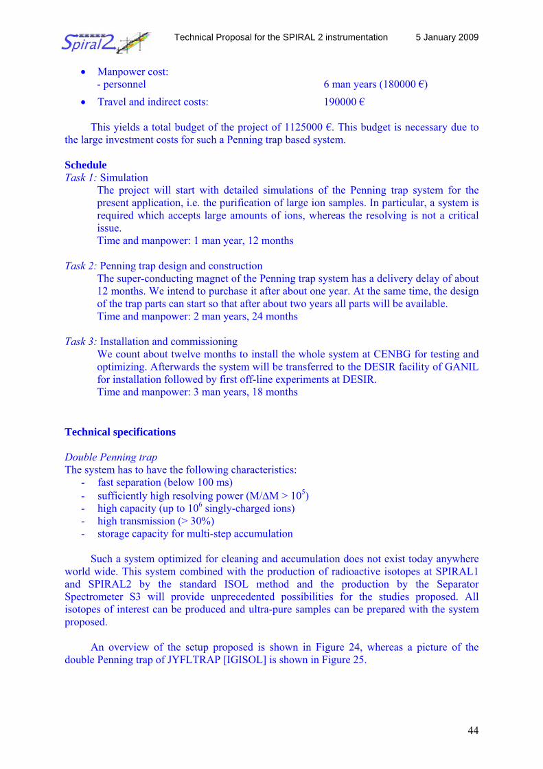
Technical Proposal for the SPIRAL 2 instrumentation 5 January 2009
44
• Manpower cost: - personnel 6 man years (180000 €)
• Travel and indirect costs: 190000 €
This yields a total budget of the project of 1125000 €. This budget is necessary due to the large investment costs for such a Penning trap based system. Schedule Task 1: Simulation
The project will start with detailed simulations of the Penning trap system for the present application, i.e. the purification of large ion samples. In particular, a system is required which accepts large amounts of ions, whereas the resolving is not a critical issue. Time and manpower: 1 man year, 12 months
Task 2: Penning trap design and construction
The super-conducting magnet of the Penning trap system has a delivery delay of about 12 months. We intend to purchase it after about one year. At the same time, the design of the trap parts can start so that after about two years all parts will be available. Time and manpower: 2 man years, 24 months
Task 3: Installation and commissioning
We count about twelve months to install the whole system at CENBG for testing and optimizing. Afterwards the system will be transferred to the DESIR facility of GANIL for installation followed by first off-line experiments at DESIR. Time and manpower: 3 man years, 18 months
Technical specifications Double Penning trap The system has to have the following characteristics:
- fast separation (below 100 ms) - sufficiently high resolving power (M/ΔM > 105) - high capacity (up to 106 singly-charged ions) - high transmission (> 30%) - storage capacity for multi-step accumulation
Such a system optimized for cleaning and accumulation does not exist today anywhere
world wide. This system combined with the production of radioactive isotopes at SPIRAL1 and SPIRAL2 by the standard ISOL method and the production by the Separator Spectrometer S3 will provide unprecedented possibilities for the studies proposed. All isotopes of interest can be produced and ultra-pure samples can be prepared with the system proposed.
An overview of the setup proposed is shown in Figure 24, whereas a picture of the double Penning trap of JYFLTRAP [IGISOL] is shown in Figure 25.
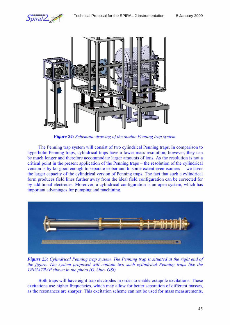
Technical Proposal for the SPIRAL 2 instrumentation 5 January 2009
45
Figure 24: Schematic drawing of the double Penning trap system.
The Penning trap system will consist of two cylindrical Penning traps. In comparison to hyperbolic Penning traps, cylindrical traps have a lower mass resolution; however, they can be much longer and therefore accommodate larger amounts of ions. As the resolution is not a critical point in the present application of the Penning traps – the resolution of the cylindrical version is by far good enough to separate isobar and to some extent even isomers – we favor the larger capacity of the cylindrical version of Penning traps. The fact that such a cylindrical form produces field lines further away from the ideal field configuration can be corrected for by additional electrodes. Moreover, a cylindrical configuration is an open system, which has important advantages for pumping and machining.
Figure 25: Cylindrical Penning trap system. The Penning trap is situated at the right end of the figure. The system proposed will contain two such cylindrical Penning traps like the TRIGATRAP shown in the photo (G. Otto, GSI).
Both traps will have eight trap electrodes in order to enable octupole excitations. These excitations use higher frequencies, which may allow for better separation of different masses, as the resonances are sharper. This excitation scheme can not be used for mass measurements,
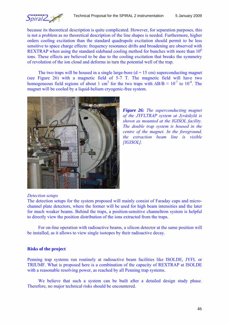
Technical Proposal for the SPIRAL 2 instrumentation 5 January 2009
46
because its theoretical description is quite complicated. However, for separation purposes, this is not a problem as no theoretical description of the line shapes is needed. Furthermore, higher orders cooling excitation than the standard quadrupole excitation should permit to be less sensitive to space charge effects: frequency resonance drifts and broadening are observed with REXTRAP when using the standard sideband cooling method for bunches with more than 106 ions. These effects are believed to be due to the cooling excitation that breaks the symmetry of revolution of the ion cloud and deforms in turn the potential well of the trap.
The two traps will be housed in a single large-bore (d = 15 cm) superconducting magnet (see Figure 26) with a magnetic field of 5-7 T. The magnetic field will have two homogeneous field regions of about 1 cm3 for the two traps with ΔB/B ≈ 10-7 to 10-8. The magnet will be cooled by a liquid-helium cryogenic-free system.
Figure 26: The superconducting magnet of the JYFLTRAP system at Jyväskylä is shown as mounted at the IGISOL facility. The double trap system is housed in the centre of the magnet. In the foreground, the extraction beam line is visible [IGISOL].
Detection setups The detection setups for the system proposed will mainly consist of Faraday cups and micro-channel plate detectors, where the former will be used for high beam intensities and the later for much weaker beams. Behind the traps, a position-sensitive channeltron system is helpful to directly view the position distribution of the ions extracted from the traps.
For on-line operation with radioactive beams, a silicon detector at the same position will be installed, as it allows to view single isotopes by their radioactive decay. Risks of the project Penning trap systems run routinely at radioactive beam facilities like ISOLDE, JYFL or TRIUMF. What is proposed here is a combination of the capacity of REXTRAP at ISOLDE with a reasonable resolving power, as reached by all Penning trap systems.
We believe that such a system can be built after a detailed design study phase. Therefore, no major technical risks should be encountered.
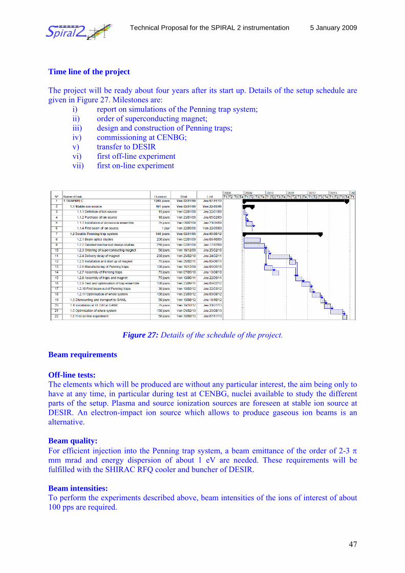
Technical Proposal for the SPIRAL 2 instrumentation 5 January 2009
47
Time line of the project The project will be ready about four years after its start up. Details of the setup schedule are given in Figure 27. Milestones are:
i) report on simulations of the Penning trap system; ii) order of superconducting magnet; iii) design and construction of Penning traps; iv) commissioning at CENBG; v) transfer to DESIR vi) first off-line experiment vii) first on-line experiment
Figure 27: Details of the schedule of the project. Beam requirements Off-line tests: The elements which will be produced are without any particular interest, the aim being only to have at any time, in particular during test at CENBG, nuclei available to study the different parts of the setup. Plasma and source ionization sources are foreseen at stable ion source at DESIR. An electron-impact ion source which allows to produce gaseous ion beams is an alternative. Beam quality: For efficient injection into the Penning trap system, a beam emittance of the order of 2-3 π mm mrad and energy dispersion of about 1 eV are needed. These requirements will be fulfilled with the SHIRAC RFQ cooler and buncher of DESIR. Beam intensities: To perform the experiments described above, beam intensities of the ions of interest of about 100 pps are required.
Technical Proposal for the SPIRAL 2 instrumentation 5 January 2009
48
References [S3] http://www-dapnia.cea.fr/Phocea/Vie_des_labos/Ast/ast_technique.php?id_ast=943 [REX] L. Weissman et al., Hyp. Interact. 132 (2001) 535 [Del08] P. Delahaye and B. Blank, Nucl. Instr. Meth. B266, (2008) 4647 [IGISOL] http://www.jyu.fi/science/laitokset/fysiikka/en/research/accelerator/igisol 2.2.6.3 The neutron detection setup TETRA
Scientific coordinator: Y. Penionzhkevich, JINR Dubna
Physics motivation It is expected that, with the advent of new machines to produce neutron-rich species like SPIRAL2, our knowledge about nuclear properties in the region close to the neutron drip-line in the region of Z=28-50 will extent considerably.
When moving further and further away from the valley of stability, the Q values for β decay increase more and more. Close to the drip line, β-delayed particle emission is observed. On the neutron-rich side, β-delayed two-neutron emission has been evidenced for 7 nuclei with branching ratios ranging from 1% to 10% (and estimated to up to 50% for 34Na). However, correlations between the two neutrons have not been searched for in these nuclei.
These correlations can give valuable information about the pairing of nucleons inside
the atomic nucleus. This information is not accessible otherwise. Neutrons are not disturbed by the Coulomb barrier and correlations should be observable outside the nucleus. So, two-neutron emission has a decisive advantage over two-proton emission.
In addition to their interest for correlation studies, the decay characteristics of these
nuclei are also of interest for the modeling of the astrophysical rapid-neutron capture process. For identifying new two-neutron emitters and for studying their decays, these isotopes
have to be implanted into a catcher, which is surrounded by high-efficiency, high-granularity β, γ and neutron detection systems. The half-life of the nucleus, the energy of the β’s and γ’s and in particular the angle between the two neutrons will be measured.
There are three areas where β-delayed two-neutron emission is possible. For the lightest
nuclei, the β-delayed two-neutron emission was experimentally well established. Search for β-delayed two-neutron emission in the Br-Rb and the Sb-Sn regions of the chart of nuclei is an interesting experimental task.
The majority of the new Pn values were deduced from the ratios of simultaneously
measured β and delayed-neutron activities. It was only in a few cases that spectroscopic data were used to determine the one or other decay property (e.g. independent Pn determinations for 93Br, 100Rb and 135Sn).
N=50, 82 and 126 shells: Systematic studies of basic nuclear structure properties of
neutron-rich isotopes for (possibly) all elements from Fe to Sn, covering all “waiting-point” nuclei in the r-process path are very important.
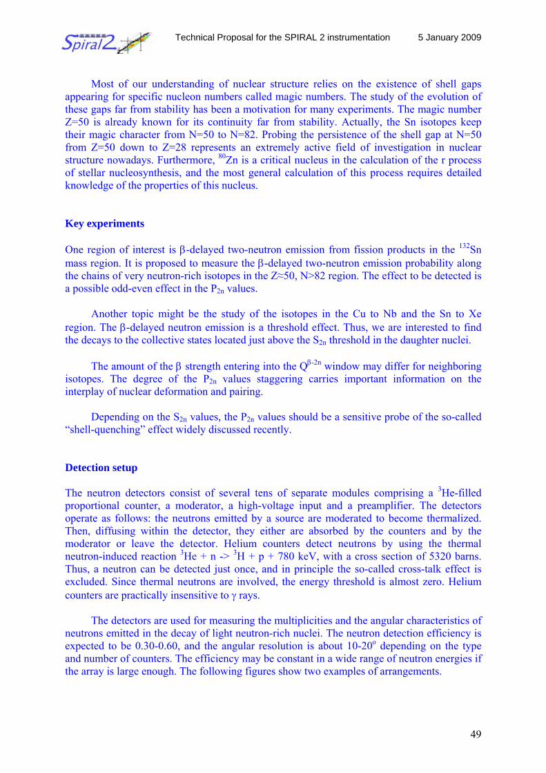
Technical Proposal for the SPIRAL 2 instrumentation 5 January 2009
49
Most of our understanding of nuclear structure relies on the existence of shell gaps
appearing for specific nucleon numbers called magic numbers. The study of the evolution of these gaps far from stability has been a motivation for many experiments. The magic number Z=50 is already known for its continuity far from stability. Actually, the Sn isotopes keep their magic character from N=50 to N=82. Probing the persistence of the shell gap at N=50 from Z=50 down to Z=28 represents an extremely active field of investigation in nuclear structure nowadays. Furthermore, 80Zn is a critical nucleus in the calculation of the r process of stellar nucleosynthesis, and the most general calculation of this process requires detailed knowledge of the properties of this nucleus. Key experiments One region of interest is β-delayed two-neutron emission from fission products in the 132Sn mass region. It is proposed to measure the β-delayed two-neutron emission probability along the chains of very neutron-rich isotopes in the Z≈50, N>82 region. The effect to be detected is a possible odd-even effect in the P2n values.
Another topic might be the study of the isotopes in the Cu to Nb and the Sn to Xe region. The β-delayed neutron emission is a threshold effect. Thus, we are interested to find the decays to the collective states located just above the S2n threshold in the daughter nuclei.
The amount of the β strength entering into the Qβ-2n window may differ for neighboring
isotopes. The degree of the P2n values staggering carries important information on the interplay of nuclear deformation and pairing.
Depending on the S2n values, the P2n values should be a sensitive probe of the so-called
“shell-quenching” effect widely discussed recently. Detection setup The neutron detectors consist of several tens of separate modules comprising a 3He-filled proportional counter, a moderator, a high-voltage input and a preamplifier. The detectors operate as follows: the neutrons emitted by a source are moderated to become thermalized. Then, diffusing within the detector, they either are absorbed by the counters and by the moderator or leave the detector. Helium counters detect neutrons by using the thermal neutron-induced reaction 3He + n -> 3H + p + 780 keV, with a cross section of 5320 barns. Thus, a neutron can be detected just once, and in principle the so-called cross-talk effect is excluded. Since thermal neutrons are involved, the energy threshold is almost zero. Helium counters are practically insensitive to γ rays.
The detectors are used for measuring the multiplicities and the angular characteristics of
neutrons emitted in the decay of light neutron-rich nuclei. The neutron detection efficiency is expected to be 0.30-0.60, and the angular resolution is about 10-20o depending on the type and number of counters. The efficiency may be constant in a wide range of neutron energies if the array is large enough. The following figures show two examples of arrangements.
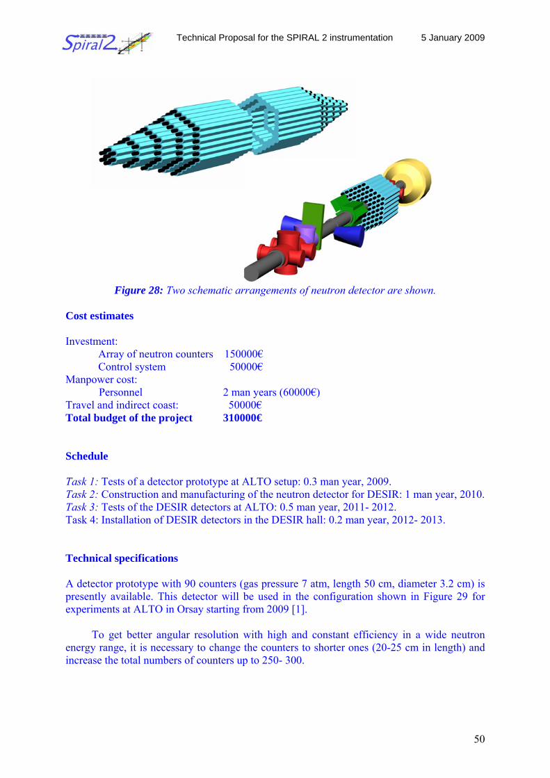
Technical Proposal for the SPIRAL 2 instrumentation 5 January 2009
50
Figure 28: Two schematic arrangements of neutron detector are shown.
Cost estimates Investment:
Array of neutron counters 150000€ Control system 50000€
Manpower cost: Personnel 2 man years (60000€) Travel and indirect coast: 50000€ Total budget of the project 310000€ Schedule Task 1: Tests of a detector prototype at ALTO setup: 0.3 man year, 2009. Task 2: Construction and manufacturing of the neutron detector for DESIR: 1 man year, 2010. Task 3: Tests of the DESIR detectors at ALTO: 0.5 man year, 2011- 2012. Task 4: Installation of DESIR detectors in the DESIR hall: 0.2 man year, 2012- 2013. Technical specifications A detector prototype with 90 counters (gas pressure 7 atm, length 50 cm, diameter 3.2 cm) is presently available. This detector will be used in the configuration shown in Figure 29 for experiments at ALTO in Orsay starting from 2009 [1].
To get better angular resolution with high and constant efficiency in a wide neutron energy range, it is necessary to change the counters to shorter ones (20-25 cm in length) and increase the total numbers of counters up to 250- 300.
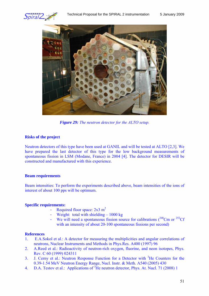
Technical Proposal for the SPIRAL 2 instrumentation 5 January 2009
51
Figure 29: The neutron detector for the ALTO setup. Risks of the project Neutron detectors of this type have been used at GANIL and will be tested at ALTO [2,3]. We have prepared the last detector of this type for the low background measurements of spontaneous fission in LSM (Modane, France) in 2004 [4]. The detector for DESIR will be constructed and manufactured with this experience. Beam requirements
Beam intensities: To perform the experiments described above, beam intensities of the ions of interest of about 100 pps will be optimum. Specific requirements:
- Required floor space: 2x3 m2 - Weight: total with shielding – 1000 kg - We will need a spontaneous fission source for calibrations (248Cm or 252Cf
with an intensity of about 20-100 spontaneous fissions per second) References 1. E.A.Sokol et al.: A detector for measuring the multiplicities and angular correlations of
neutrons, Nuclear Instruments and Methods in Phys.Res. A400 (1997) 96 2. A.Reed et al.: Radioactivity of neutron-rich oxygen, fluorine, and neon isotopes, Phys.
Rev. C 60 (1999) 024311 3. J. Cerny et al.: Neutron Response Function for a Detector with 3He Counters for the
0.39-1.54 MeV Neutron Energy Range, Nucl. Instr. & Meth. A540 (2005) 430 4. D.A. Testov et al.: Applications of 3He neutron detector, Phys. At. Nucl. 71 (2008) 1
Technical Proposal for the SPIRAL 2 instrumentation 5 January 2009
52
2.2.6.4 Neutron spectroscopy at DESIR
Scientific coordinators: D. Cano Ott, CIEMAT Madrid N.A. Orr, LPC Caen
The physics case The accurate determination of the β-decay strength function Sβ(E) for nuclei lying far from stability is important for many facets of nuclear structure physics, nuclear astrophysics and nuclear technologies including the interpretation of reactor neutrino oscillation experiments, the production of certain elements in the universe or the calculation of the decay heat and particle emission probabilities of nuclear fuels [KLAP81, KLAP82, KLAP76, MILL82]. For example, β-decay by neutron-rich nuclei plays a key role in the astrophysical r-process, during which heavy elements are built up by successive neutron capture and β-decay.
The decay of very neutron-rich nuclei is, however, owing to the high Qβ and relatively low binding energies of the daughter nuclei, often associated with delayed neutron emission from the population of unbound levels. In order, therefore, to map the full decay strength, a system for detecting neutrons with energies up to some 10 MeV with good efficiency and energy resolution is required. As the most neutron-rich systems can decay through the emission of two or more neutrons, a multi-neutron detection capability is also highly desirable. In such cases, information may be derived concerning neutron-neutron correlations and the sequential or direct character of the decay.
It is proposed, therefore, to install at DESIR a new neutron time-of-flight spectrometer
in order to fulfill these goals. Complementarily with other DESIR experimental devices The neutron time-of-flight (nTOF) spectrometer will be used on both a dedicated beam line and, in certain “compact” configurations, on other beam lines in conjunction with other devices. The separate use of a high efficiency 4π neutron long counter would provide valuable information on the total neutron emission probability over the full neutron energy range. The nTOF spectrometer will require the same tape system for ion implantation and β−detector as foreseen for the TAS setup. Many of the measurements, including in particular spectroscopic studies, will require the use of an efficient array of high resolution germanium detectors or, alternatively, an array of high resolution inorganic scintillators such as LaBr3 or LaCl3. The use of the double Penning trap system (which allows isotopic purification of the samples) may also prove to be valuable to suppress the level of contaminants and thus reduce the systematic uncertainties in the measurements. For this reason, the installation of the nTOF spectrometer behind the trap assisted spectroscopy setup should be envisaged. The experimental setup and technical specifications The neutron energies will be determined by a standard time-of-flight technique whereby the “start” is provided by the β–detector (silicon or plastic scintillation detector) and the “stop” by the neutron detector module(s) which fires. The major source of systematic error in this technique, in particular for low beam intensities and/or low neutron-emission probabilities, is
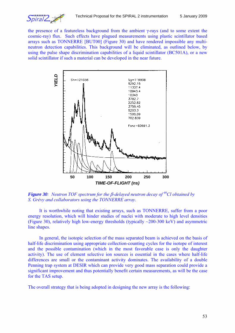
Technical Proposal for the SPIRAL 2 instrumentation 5 January 2009
53
the presence of a featureless background from the ambient γ-rays (and to some extent the cosmic-ray) flux. Such effects have plagued measurements using plastic scintillator based arrays such as TONNERRE [BUT00] (Figure 30) and have rendered impossible any multi-neutron detection capabilities. This background will be eliminated, as outlined below, by using the pulse shape discrimination capabilities of a liquid scintillator (BC501A), or a new solid scintillator if such a material can be developed in the near future.
Figure 30: Neutron TOF spectrum for the β-delayed neutron decay of 46Cl obtained by S. Grévy and collaborators using the TONNERRE array.
It is worthwhile noting that existing arrays, such as TONNERRE, suffer from a poor energy resolution, which will hinder studies of nuclei with moderate to high level densities (Figure 30), relatively high low-energy thresholds (typically ~200-300 keV) and asymmetric line shapes.
In general, the isotopic selection of the mass separated beam is achieved on the basis of half-life discrimination using appropriate collection-counting cycles for the isotope of interest and the possible contamination (which in the most favorable case is only the daughter activity). The use of element selective ion sources is essential in the cases where half-life differences are small or the contaminant activity dominates. The availability of a double Penning trap system at DESIR which can provide very good mass separation could provide a significant improvement and thus potentially benefit certain measurements, as will be the case for the TAS setup. The overall strategy that is being adopted in designing the new array is the following:
50 100 150 200 250 300
YIEL
D
TIME-OF-FLIGHT (ns)
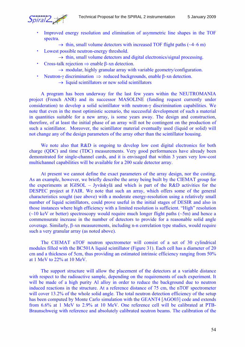
Technical Proposal for the SPIRAL 2 instrumentation 5 January 2009
54
• Improved energy resolution and elimination of asymmetric line shapes in the TOF spectra.
→ thin, small volume detectors with increased TOF flight paths (~4–6 m) • Lowest possible neutron-energy threshold.
→ thin, small volume detectors and digital electronics/signal processing. • Cross-talk rejection ⇒ enable β-xn detection.
→ modular, highly granular array with variable geometry/configuration. • Neutron-γ discrimination ⇒ reduced backgrounds, enable β-xn detection.
→ liquid scintillators or new solid scintillators
A program has been underway for the last few years within the NEUTROMANIA project (French ANR) and its successor MASOLINE (funding request currently under consideration) to develop a solid scintillator with neutron-γ discrimination capabilities. We note that even in the most optimistic scenario, the successful development of such a material in quantities suitable for a new array, is some years away. The design and construction, therefore, of at least the initial phase of an array will not be contingent on the production of such a scintillator. Moreover, the scintillator material eventually used (liquid or solid) will not change any of the design parameters of the array other than the scintillator housing.
We note also that R&D is ongoing to develop low cost digital electronics for both
charge (QDC) and time (TDC) measurements. Very good performances have already been demonstrated for single-channel cards, and it is envisaged that within 3 years very low-cost multichannel capabilities will be available for a 200 scale detector array.
At present we cannot define the exact parameters of the array design, nor the costing.
As an example, however, we briefly describe the array being built by the CIEMAT group for the experiments at IGISOL – Jyväskylä and which is part of the R&D activities for the DESPEC project at FAIR. We note that such an array, which offers some of the general characteristics sought (see above) with a moderate energy-resolution using a relatively small number of liquid scintillators, could prove useful in the initial stages of DESIR and also in those instances where high efficiency with a limited resolution is sufficient. “High” resolution (~10 keV or better) spectroscopy would require much longer flight paths (~5m) and hence a commensurate increase in the number of detectors to provide for a reasonable solid angle coverage. Similarly, β-xn measurements, including n-n correlation type studies, would require such a very granular array (as noted above).
The CIEMAT nTOF neutron spectrometer will consist of a set of 30 cylindrical
modules filled with the BC501A liquid scintillator (Figure 31). Each cell has a diameter of 20 cm and a thickness of 5cm, thus providing an estimated intrinsic efficiency ranging from 50% at 1 MeV to 22% at 10 MeV.
The support structure will allow the placement of the detectors at a variable distance
with respect to the radioactive sample, depending on the requirements of each experiment. It will be made of a high purity Al alloy in order to reduce the background due to neutron induced reactions in the structure. At a reference distance of 75 cm, the nTOF spectrometer will cover 13.2% of the whole solid angle. The total neutron detection efficiency of the setup has been computed by Monte Carlo simulation with the GEANT4 [AGO03] code and extends from 6.6% at 1 MeV to 2.9% at 10 MeV. One reference cell will be calibrated at PTB-Braunschweig with reference and absolutely calibrated neutron beams. The calibration of the
Technical Proposal for the SPIRAL 2 instrumentation 5 January 2009
55
complete spectrometer will be made in-situ with on-line and off-line neutron sources, including a 252Cf source.
Figure 31: CIEMAT nTOF spectrometer setup as it will be used at IGISOL- Jyväskylä.
The spectrometer will be supplemented by ancillary detectors (Figure 31): silicon or
plastic scintillation detectors for the β-particles and an array of Ge detectors for the β-γ and β-γ-n decays. They should be placed close to the source and the amount of dead material should be minimized, imposing restrictions on the construction of the beam pipe. The digital data acquisition system will provide the capacity to analyze the shape of the BC501A light output, so as to provide for the neutron-gamma discrimination off-line.
Coincident β-n and β-γ-n events will be recorded in order to determine the delayed
neutron emission probabilities, energies and decay schemes. The β-detector in close geometry will be used as a trigger and provide the start signal for the time-of-flight. The energy of the delayed neutrons will be derived from the time difference between β-trigger and a signal in the neutron spectrometer. The γ-ray background in the neutron detectors will be rejected by time-of-flight (for prompt coincident γ-rays) and, as noted already, by the pulse-shape analysis.
The overall time resolution of the β-n coincidence setup will be 1ns. With such a value, the energy resolution of the spectrometer will range between 160 keV at 1 MeV to 3 MeV at 10 MeV for a flight path of 75 cm.
The detector assembly will be complemented by a fast tape transport system which will
allow the activity to be collected and subsequently moved into the counting position and for it to be evacuated at the end of the counting period. The whole system should allow reasonably easy displacement to a storage position.
Technical Proposal for the SPIRAL 2 instrumentation 5 January 2009
56
Cost estimates The costs for the 30 module CIEMAT neutron time-of-flight spectrometer are provided as an example, and have been estimated as listed below. We note that for a larger array the costing will scale to first order linearly, although it is envisaged that the ongoing developments in digital electronics and DAQ will reduce the costs per channel as will the construction of a large number of detector modules. • Investment: − Neutron time-of-flight spectrometer: 310 000 € − Supporting structure: 50 000 € − Beta detector: the same as for the TAS [3000 €] − Electronics: 40 000 € − Data acquisition system 45 000 €
A fully digital data acquisition system based on 12 bit and 1 Gsample/s flash ADCs developed by CIEMAT.
− Tape transport system and vacuum beam pipe: [100000 €] (the same as for the TAS)
TOTAL: 445 000 € • Manpower costs: − 1 person-year 30 000 € • Travel and running costs: 15 000 € Schedule The CIEMAT spectrometer, including the electronics and data acquisition, currently under design and construction will be ready by mid-2010. The mechanical structure is already under design and will be built in 2009. The first tests of the various components and subsequent β–decay measurements will be performed in 2010 at IGISOL-JYFL using the Penning trap as an isotopic purification filter.
Remaining tasks: tape transport system design and construction. The fast tape transport system remains to be designed and constructed. It will be the same as that used for the TAS setup. Time and manpower: 18 months, 1 person-year Time line of the project The construction of the CIEMAT spectrometer and delivery of the neutron detector cells will require 18 months. The construction of the digitizers for the DACQ will run in parallel and require an additional 18 months. Both activities have commenced.
The general integration of the system and the first off-line and in-beam tests will require 2 months.

Technical Proposal for the SPIRAL 2 instrumentation 5 January 2009
57
Beam requirements Beam quality: The emittance should be such as to allow an efficient beam collimation down to few millimeters for direct implantation on the tape system at the central position of the spectrometer, avoiding contamination of the beam vacuum tube parts in the proximity of the spectrometer. Beam intensity: The exact requirements are a function of the type of measurement to be undertaken, the neutron emission probability of the nucleus understudy and the number of individual transitions. As an example, in order to perform experiments acquiring the necessary statistics within a reasonable timeframe, will require beam intensities of order 103−104 pps for β−γ−n type coincidence measurements. References [KLAP81] Klapdor, H.V. et al., Z. Phys. A299, 213 (1981) [KLAP76] Klapdor, H.V., Phys Lett 65B, (1976) 35 [KLAP82] Klapdor, H.V. et al., Astrophysical J. 242 (1982) L49 [MILL82] Mill, A.J., Jou. Soc. Rad. Prot. 2, (1982) 3 [AGO03] Agostinelli, S., Nucl. Instr. Meth. A506 (2003) 250 [BUT00] Buta, A. et al., Nucl. Instr. Meth. A455 (2000) 412 2.2.6.5 Fast-timing experiments at DESIR Scientific coordinators: Gary Simpson, LPSC Grenoble Henryk Mach, Uni. Uppsala Introduction One of the most important parameters in nuclear spectroscopy is the lifetime of an excited state, which provides a direct insight into the properties of the state. Lifetime measurements are also an important input parameters into the evaluation of magnetic and quadrupole moment measurements and even critical for dynamic corrections in particle transfer reactions [1]. The fast-timing technique [2, 3] allows measurements to be made of the lifetimes of excited states, produced following β decay, in the ps to ns time range. The technique can be used with relatively few statistics, therefore is perfectly adapted to the study of the properties of exotic nuclei, which are difficult to produce. Application of the fast-timing technique at DESIR, with beams of exotic nuclei, represents an excellent opportunity to study nuclei at the extremes of current knowledge and to test the predictive power of nuclear models far from stability. Examples of Physics Cases Lifetime measurements are particularly useful for distinguishing between collective, single-particle and isomeric behavior of excited nuclear states. In favorable cases, for instance
Technical Proposal for the SPIRAL 2 instrumentation 5 January 2009
58
isomeric states, a simple lifetime measurement can give clear information regarding the main orbitals present in a nuclear state.
The evolution of shell structure far from stability in medium-heavy regions has not yet been fully established. For instance questions still remain regarding the regions around the supposed doubly magic nucleus 78Ni. Currently, not enough data exists to see if 78Ni can be used as an inert core for shell-model calculations. Lifetime measurements will be sensitive tests to model predictions and any hint of deviation from this behavior will be immediately obvious. The question of how nuclear structure evolves beyond 132Sn. also remains open. One example of deviation from predicted behavior is the anomalously low B(E2;0gs
+→21+) value
for 136Te which cannot be perfectly reproduced by theoretical calculations [4]. More lifetime data are needed in this region to see if the problem lies with the effective charges used or the interactions. Lifetime measurements also allow insights into the mechanisms responsible for shape changes, by allowing the identification of certain key orbits responsible for these changes. The onset and evolution of octupole modes can also similarly be studied. Lifetime measurements allow models, such as the quasi-particle rotor model, used to describe deformed nuclei, to be tested far from stability and to search for any hints of new modes of nuclear excitations. Quasi-particle rotor models allow the energies and lifetimes of states within rotational bands to be predicted. Lifetime measurements therefore put severe constraints on these predictions, which are sensitive to small variations in deformation. Experimental Method The fast-timing technique is a direct method for lifetime measurements which relies on the fast response of carefully selected plastic and LaBr3 scintillator detectors to β particles and γ-rays respectively. The choice of a thin plastic scintillator in which β particles have the same energy loss, independent of their energy, is an essential part of the set up and simplifies walk corrections. The signals from the anodes of each scintillator detector are fed into constant fraction discriminators, whose outputs are then used to start and stop a time-to-amplitude converter (TAC). These signals alone however are not enough for a lifetime measurement and a careful selection of the γ-ray energy depopulating the state must be made. Unfortunately the energy resolution of the very best scintillators available today does not offer this selection. The LaBr3(Ce) scintillator has an energy resolution of around 3 %, which is generally not good enough to uniquely select the β−γ coincidence of interest, without background influencing the time spectrum obtained. Adding the energy signal of a high resolution γ-ray detector, such as a Ge detector, to the selected coincidence (β-γ(Ge)-γ(LaBr3)) allows unique selection of a decay cascade. The timing signal of the Ge detector is not used, only its energy selectivity. One necessary condition is that the lifetime of the state whose γ ray energy is selected by the Ge detector must be short compared with the lifetime of interest. The efficiencies of the Ge and scintillator setups must therefore be as high as possible whilst maintaining optimal time resolution. Figure 32 shows a typical setup, with one Ge detector removed to allow better observation of the other detectors.
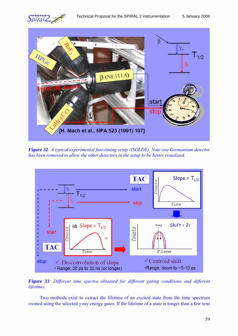
Technical Proposal for the SPIRAL 2 instrumentation 5 January 2009
59
Figure 32: A typical experimental fast-timing setup (ISOLDE). Note one Germanium detector has been removed to allow the other detectors in the setup to be better visualized.
Figure 33: Different time spectra obtained for different gating conditions and different lifetimes.
Two methods exist to extract the lifetime of an excited state from the time spectrum created using the selected γ-ray energy gates. If the lifetime of a state is longer than a few tens
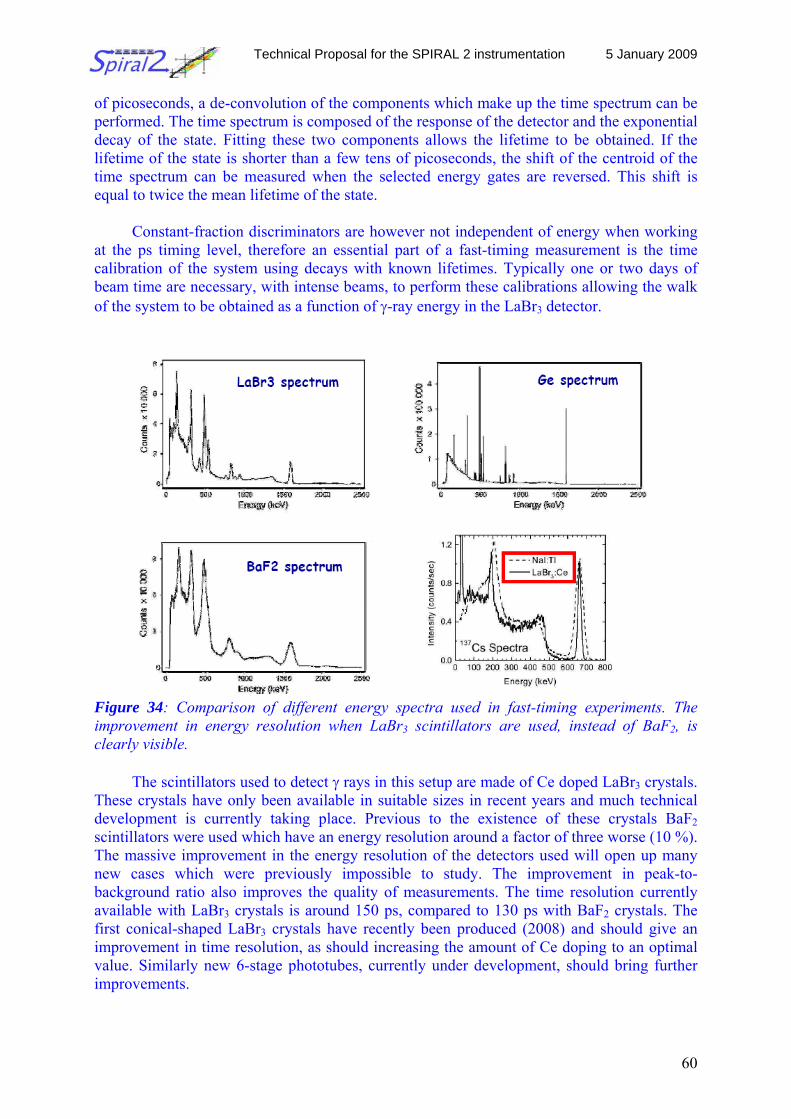
Technical Proposal for the SPIRAL 2 instrumentation 5 January 2009
60
of picoseconds, a de-convolution of the components which make up the time spectrum can be performed. The time spectrum is composed of the response of the detector and the exponential decay of the state. Fitting these two components allows the lifetime to be obtained. If the lifetime of the state is shorter than a few tens of picoseconds, the shift of the centroid of the time spectrum can be measured when the selected energy gates are reversed. This shift is equal to twice the mean lifetime of the state.
Constant-fraction discriminators are however not independent of energy when working
at the ps timing level, therefore an essential part of a fast-timing measurement is the time calibration of the system using decays with known lifetimes. Typically one or two days of beam time are necessary, with intense beams, to perform these calibrations allowing the walk of the system to be obtained as a function of γ-ray energy in the LaBr3 detector.
Figure 34: Comparison of different energy spectra used in fast-timing experiments. The improvement in energy resolution when LaBr3 scintillators are used, instead of BaF2, is clearly visible.
The scintillators used to detect γ rays in this setup are made of Ce doped LaBr3 crystals. These crystals have only been available in suitable sizes in recent years and much technical development is currently taking place. Previous to the existence of these crystals BaF2 scintillators were used which have an energy resolution around a factor of three worse (10 %). The massive improvement in the energy resolution of the detectors used will open up many new cases which were previously impossible to study. The improvement in peak-to-background ratio also improves the quality of measurements. The time resolution currently available with LaBr3 crystals is around 150 ps, compared to 130 ps with BaF2 crystals. The first conical-shaped LaBr3 crystals have recently been produced (2008) and should give an improvement in time resolution, as should increasing the amount of Ce doping to an optimal value. Similarly new 6-stage phototubes, currently under development, should bring further improvements.
Technical Proposal for the SPIRAL 2 instrumentation 5 January 2009
61
Complementarities to other lifetime measurements In addition to the fast-timing technique measurements such as Coulomb excitation can also give access to the lifetime of an excited state. However, Coulomb excitation can be difficult to use with odd-even or odd-odd nuclei where the multipolarities of low-lying transitions are often unknown for exotic nuclei. Fast timing therefore gives complementary information to Coulomb excitation studies and gives access to many non-yrast states not accessible to Coulomb excitation. Measurements using plungers with radioactive beams have recently been achieved. Plunger measurements operate over a similar lifetime range though generally require higher statistics. Estimated Costs Currently all available equipment required to perform initial fast-timing experiments exists within the collaboration, however we will need access to two large-volume Ge detectors and a tape system (only for certain experiments). Over a longer time range funds are required for a few (three) new LaBr3 crystals with improved conical shape and enhanced Ce doping (cost ~7k Euro each) and several (four) new photomultiplier tubes (~3 kEuro each). Time Schedule For several years the fast-timing collaboration has been undertaking measurements at a variety of facilities such as ISOLDE, JYFL, GANIL, ILL and Oak Ridge. All necessary equipment exists within the collaboration to perform these experiments and we are immediately ready to perform experiments. Technical developments are however afoot to improve the quality of the time signals from the LaBr3(Ce) scintillators and we hope to have new conical crystals and new 6-dynode phototubes ready for the start up of DESIR which will create an improved setup within the next few years. Technical Specifications To perform fast-timing measurements we require 2 LaBr3 detectors (plus a spare), a plastic scintillator (with PMT) and 2 large volume Ge detectors. The resolution of the LaBr3 detectors should be 150 ps or lower. These scintillator detectors exist already and improved performances are hoped for in the near future. The Ge detectors do not exist in the fast-timing collaboration and are usually supplied by the host laboratory. In certain cases a tape station is also necessary. The fast-timing collaboration has it own data acquisition system. However, if a suitable acquisition system (with around 20 channels) is available at the host lab this can be used.
As the gains of photomultiplier tubes can drift significantly with small temperature
variations it is necessary to have a stable climate in the experimental hall, hence air conditioning.
The setup requires a floor space area of about 3 x 4 m2, centered on the beam spot.
Technical Proposal for the SPIRAL 2 instrumentation 5 January 2009
62
Beam quality A beam spot of 1 mm2 is requested, though successful experiments have been performed with beams of 3 x 3 mm2 (JYFL). The small beam spot is required due to the finite speed of light (3 ps/mm) which broadens the time resolution of the system. Beam intensity Typically a few thousand ions/s are required for such measurements, although meaningful results can be obtained with rates as low as about one hundred ions/s. References [1] J. R. Terry et al., Phys. Rev. C 77 (2008) 014316 [2] H. Mach et al., Nucl. Instr. Meth. A280 (1989) 49 [3] M. Moszynski and H. Mach, Nucl. Instr. Meth. A277 (1989) 407 [4] D.C. Radford et al., Phys. Rev. Lett. 88 (2002) 222501 2.2.6.6 The general purpose decay stations Scientific coordinator: M.J.G. Borge, CSIC Madrid Two general purpose decay station are foreseen in the DESIR hall. These stations are to be used by experiments which can be mounted and dismounted within a rather limited time frame, typically one week. These experiments include β-decay experiments with only a few detectors and without the need ultra-high beam purity as only reachable behind the Penning trap described above. Further, when studying heavier elements γ-ray and neutron detection becomes important. Physics case The new exotic nuclei accessible at SPIRAL2 will offer many new opportunities to study pairing, mainly in systems with strong density variations. Since the number of nucleons can be precisely controlled, nuclei are wonderful laboratories of many-body pairing in various strength regimes. Two-neutron transfer on 56Ni, 64Ge and 72Kr can be used for these studies. The study of the β decay of 80Zr and 100Sn would yield important information.
Long-lived (>100ms) high-spin isomers offer the possibility to study novel and exotic
decay modes. These, at least in some cases, will be most-sensitively studied with ~50 keV ISOL beams. Spin-gap isomers near doubly magic closed-shell nuclei offer the chance to measure properties of single-particle states in order to test predictions of the nuclear shell model.
Experimental setup
The study of unbound excited states of nuclei includes the simultaneous detection of several charge particles emitted in a wide energy range. This puts several constrains on the detection
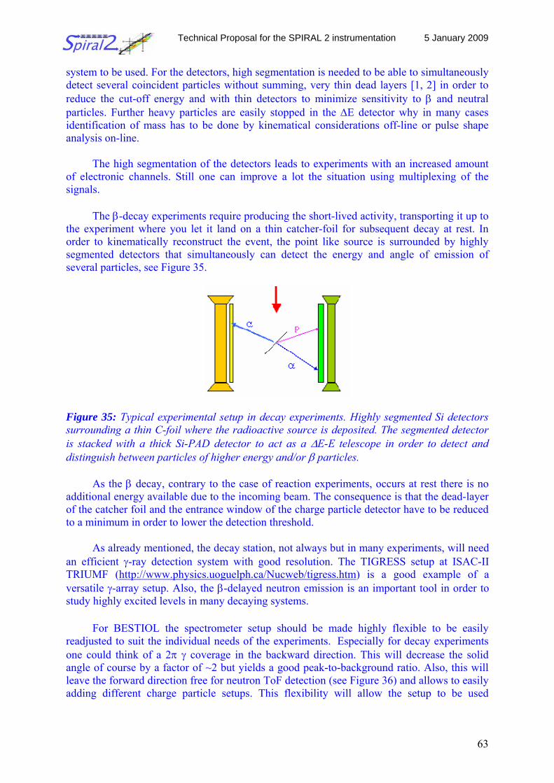
Technical Proposal for the SPIRAL 2 instrumentation 5 January 2009
63
system to be used. For the detectors, high segmentation is needed to be able to simultaneously detect several coincident particles without summing, very thin dead layers [1, 2] in order to reduce the cut-off energy and with thin detectors to minimize sensitivity to β and neutral particles. Further heavy particles are easily stopped in the ΔE detector why in many cases identification of mass has to be done by kinematical considerations off-line or pulse shape analysis on-line.
The high segmentation of the detectors leads to experiments with an increased amount
of electronic channels. Still one can improve a lot the situation using multiplexing of the signals.
The β-decay experiments require producing the short-lived activity, transporting it up to the experiment where you let it land on a thin catcher-foil for subsequent decay at rest. In order to kinematically reconstruct the event, the point like source is surrounded by highly segmented detectors that simultaneously can detect the energy and angle of emission of several particles, see Figure 35.
Figure 35: Typical experimental setup in decay experiments. Highly segmented Si detectors surrounding a thin C-foil where the radioactive source is deposited. The segmented detector is stacked with a thick Si-PAD detector to act as a ΔE-E telescope in order to detect and distinguish between particles of higher energy and/or β particles.
As the β decay, contrary to the case of reaction experiments, occurs at rest there is no additional energy available due to the incoming beam. The consequence is that the dead-layer of the catcher foil and the entrance window of the charge particle detector have to be reduced to a minimum in order to lower the detection threshold.
As already mentioned, the decay station, not always but in many experiments, will need
an efficient γ-ray detection system with good resolution. The TIGRESS setup at ISAC-II TRIUMF (http://www.physics.uoguelph.ca/Nucweb/tigress.htm) is a good example of a versatile γ-array setup. Also, the β-delayed neutron emission is an important tool in order to study highly excited levels in many decaying systems.
For BESTIOL the spectrometer setup should be made highly flexible to be easily readjusted to suit the individual needs of the experiments. Especially for decay experiments one could think of a 2π γ coverage in the backward direction. This will decrease the solid angle of course by a factor of ~2 but yields a good peak-to-background ratio. Also, this will leave the forward direction free for neutron ToF detection (see Figure 36) and allows to easily adding different charge particle setups. This flexibility will allow the setup to be used
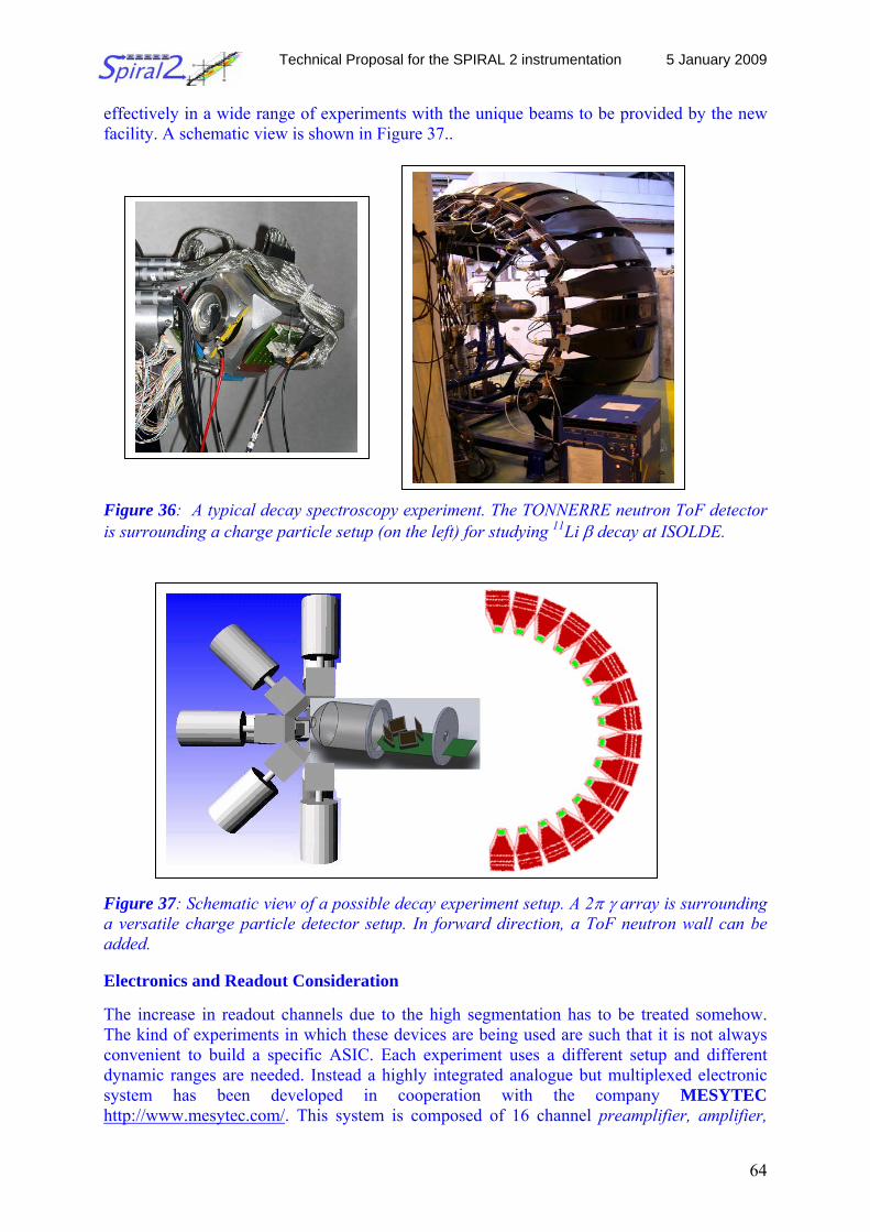
Technical Proposal for the SPIRAL 2 instrumentation 5 January 2009
64
effectively in a wide range of experiments with the unique beams to be provided by the new facility. A schematic view is shown in Figure 37.. Figure 36: A typical decay spectroscopy experiment. The TONNERRE neutron ToF detector is surrounding a charge particle setup (on the left) for studying 11Li β decay at ISOLDE. Figure 37: Schematic view of a possible decay experiment setup. A 2π γ array is surrounding a versatile charge particle detector setup. In forward direction, a ToF neutron wall can be added. Electronics and Readout Consideration The increase in readout channels due to the high segmentation has to be treated somehow. The kind of experiments in which these devices are being used are such that it is not always convenient to build a specific ASIC. Each experiment uses a different setup and different dynamic ranges are needed. Instead a highly integrated analogue but multiplexed electronic system has been developed in cooperation with the company MESYTEC http://www.mesytec.com/. This system is composed of 16 channel preamplifier, amplifier,
Technical Proposal for the SPIRAL 2 instrumentation 5 January 2009
65
timing and discriminator boards MTM-16, coupled via a 20 line twisted pair cable to a single width VME sequencer and ADC MDI-2 having two buses each handling 256 channels. The MDI-2 includes 12 bit high quality ADCs with a response of 100 Msamples/s and a bus. With this system one can, using only one VME crate, handle up to 5000 detector channels with spectroscopy resolution in a versatile way, and thus be able to adapt the system to any detector combination. 1. U.C. Bergmann, H.O.U. Fynbo, O. Tengblad, Nucl. Instr. Meth. A 515 (2003) 657 2. O. Tengblad et al., Nucl. Instr. Meth. A 525 (2004) 458 2.2.7 The MLL Trap setup Scientific coordinator: P. Thirolf, University of Munich Introduction and physics case Like few other observables, the mass of an atom and its inherent connection with the atomic and nuclear binding energy is a fundamental and unique property of each specific atomic nucleus. Nuclear ground state properties like its mass can be determined in a nuclear-model independent way by applying atomic physics techniques like Penning-trap based mass spectrometry. Thus, precise mass values are important for a variety of applications, ranging from nuclear-structure studies like the investigation of shell closures and the onset of deformation, tests of nuclear mass models and mass formulas, to tests of the weak interaction and of the Standard Model. The required relative accuracy ranges from 10-5 to below 10-8 for radionuclides, which most often have half-lives well below 1 s. Substantial progress in Penning trap mass spectrometry has made this method a prime choice for precision measurements on rare isotopes [Bla2006]. The technique has the potential to provide high accuracy and sensitivity even for very short-lived nuclides. Furthermore, ion traps can be used and offer advantages for precision decay studies. For measurements of nuclear masses, MLLTRAP in its final setup stage will offer a high accuracy aiming at a relative mass uncertainty of about 10-9 that can be reached by employing highly-charged ions. This accuracy limit is important for fundamental interaction tests, but also allows for studies of the fine structure of the nuclear mass surface with unprecedented accuracy, whenever required. Instead of pushing for highest accuracy, the high charge state of the ions can also be used to reduce the storage time of the ions, hence making measurements on even shorter-lived isotopes possible.
One of the vivid questions in the context of the Standard Model of nuclear and particle physics is the confirmation of the unitarity of the quark mixing matrix (Cabibbo-Kobayashi-Maskawa matrix, ‘CKM matrix’), debated already during the past decades. Nuclear physics can contribute decisively to this fundamental question by precision studies targeting the up-down quark-mixing matrix element Vud of the CKM matrix. This parameter can today best be determined by nuclear β-decay studies of (superallowed) 0+ 0+ transitions. Significant progress and therefore a much improved determination of this important quantity can be achieved by high-precision mass (i.e. Q value) and decay measurements and by improved theoretical calculations of ingredients necessary to extract the fundamental information searched for [Har2005].
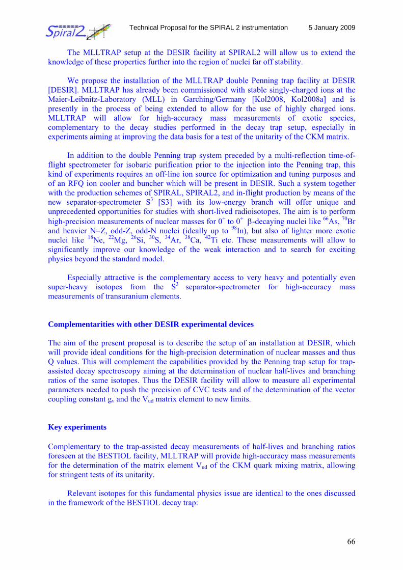
Technical Proposal for the SPIRAL 2 instrumentation 5 January 2009
66
The MLLTRAP setup at the DESIR facility at SPIRAL2 will allow us to extend the knowledge of these properties further into the region of nuclei far off stability.
We propose the installation of the MLLTRAP double Penning trap facility at DESIR
[DESIR]. MLLTRAP has already been commissioned with stable singly-charged ions at the Maier-Leibnitz-Laboratory (MLL) in Garching/Germany [Kol2008, Kol2008a] and is presently in the process of being extended to allow for the use of highly charged ions. MLLTRAP will allow for high-accuracy mass measurements of exotic species, complementary to the decay studies performed in the decay trap setup, especially in experiments aiming at improving the data basis for a test of the unitarity of the CKM matrix.
In addition to the double Penning trap system preceded by a multi-reflection time-of-
flight spectrometer for isobaric purification prior to the injection into the Penning trap, this kind of experiments requires an off-line ion source for optimization and tuning purposes and of an RFQ ion cooler and buncher which will be present in DESIR. Such a system together with the production schemes of SPIRAL, SPIRAL2, and in-flight production by means of the new separator-spectrometer S3 [S3] with its low-energy branch will offer unique and unprecedented opportunities for studies with short-lived radioisotopes. The aim is to perform high-precision measurements of nuclear masses for 0+ to 0+ β-decaying nuclei like 66As, 70Br and heavier N=Z, odd-Z, odd-N nuclei (ideally up to 98In), but also of lighter more exotic nuclei like 18Ne, 22Mg, 26Si, 30S, 34Ar, 38Ca, 42Ti etc. These measurements will allow to significantly improve our knowledge of the weak interaction and to search for exciting physics beyond the standard model.
Especially attractive is the complementary access to very heavy and potentially even
super-heavy isotopes from the S3 separator-spectrometer for high-accuracy mass measurements of transuranium elements. Complementarities with other DESIR experimental devices The aim of the present proposal is to describe the setup of an installation at DESIR, which will provide ideal conditions for the high-precision determination of nuclear masses and thus Q values. This will complement the capabilities provided by the Penning trap setup for trap- assisted decay spectroscopy aiming at the determination of nuclear half-lives and branching ratios of the same isotopes. Thus the DESIR facility will allow to measure all experimental parameters needed to push the precision of CVC tests and of the determination of the vector coupling constant gv and the Vud matrix element to new limits. Key experiments Complementary to the trap-assisted decay measurements of half-lives and branching ratios foreseen at the BESTIOL facility, MLLTRAP will provide high-accuracy mass measurements for the determination of the matrix element Vud of the CKM quark mixing matrix, allowing for stringent tests of its unitarity.
Relevant isotopes for this fundamental physics issue are identical to the ones discussed in the framework of the BESTIOL decay trap:
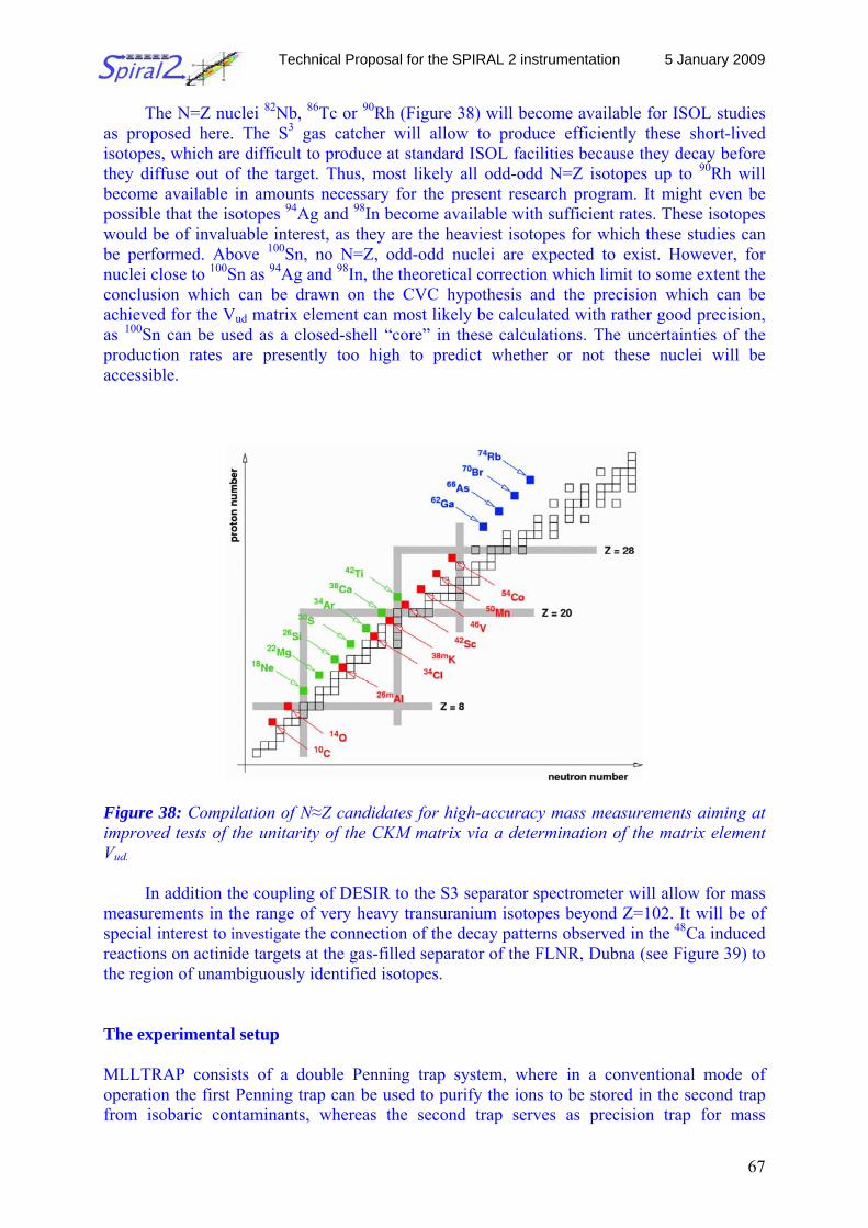
Technical Proposal for the SPIRAL 2 instrumentation 5 January 2009
67
The N=Z nuclei 82Nb, 86Tc or 90Rh (Figure 38) will become available for ISOL studies as proposed here. The S3 gas catcher will allow to produce efficiently these short-lived isotopes, which are difficult to produce at standard ISOL facilities because they decay before they diffuse out of the target. Thus, most likely all odd-odd N=Z isotopes up to 90Rh will become available in amounts necessary for the present research program. It might even be possible that the isotopes 94Ag and 98In become available with sufficient rates. These isotopes would be of invaluable interest, as they are the heaviest isotopes for which these studies can be performed. Above 100Sn, no N=Z, odd-odd nuclei are expected to exist. However, for nuclei close to 100Sn as 94Ag and 98In, the theoretical correction which limit to some extent the conclusion which can be drawn on the CVC hypothesis and the precision which can be achieved for the Vud matrix element can most likely be calculated with rather good precision, as 100Sn can be used as a closed-shell “core” in these calculations. The uncertainties of the production rates are presently too high to predict whether or not these nuclei will be accessible.
Figure 38: Compilation of N≈Z candidates for high-accuracy mass measurements aiming at improved tests of the unitarity of the CKM matrix via a determination of the matrix element Vud.
In addition the coupling of DESIR to the S3 separator spectrometer will allow for mass measurements in the range of very heavy transuranium isotopes beyond Z=102. It will be of special interest to investigate the connection of the decay patterns observed in the 48Ca induced reactions on actinide targets at the gas-filled separator of the FLNR, Dubna (see Figure 39) to the region of unambiguously identified isotopes.
The experimental setup MLLTRAP consists of a double Penning trap system, where in a conventional mode of operation the first Penning trap can be used to purify the ions to be stored in the second trap from isobaric contaminants, whereas the second trap serves as precision trap for mass
Technical Proposal for the SPIRAL 2 instrumentation 5 January 2009
68
measurements. However, MLLTRAP aims at an improved accuracy of the order of δm/m ~ 10-9 that can only be attained with highly charged ions. In this case isobaric purification in the buffer gas of the first trap cannot be performed any longer due to charge exchange processes induced by the buffer gas. Instead the purification has to be performed outside the Penning trap system. Therefore in MLLTRAP the Penning trap will be preceded by a Multi-Reflection Time-of-Flight spectrometer [Pla2008], allowing to reach mass resolving powers of about 105 at a transmission efficiency of about 50%. This system is presently developed by the Giessen group. A prototype will be tested at the MLL in Garching and subsequently duplicated for MLLTRAP. It should be stressed that this system is very fast (order of μs), thus allowing in itself for mass measurements of very short-lived species (at the expense of a reduced mass resolving power compared to Penning trap measurements).
Figure 39: Excerpt of the chart of nuclides in the region of superheavy elements. Indicated regions: Green: nuclides where the decay chains of the heaviest at SHIP synthesized elements (Z=110-112). Brown: at Dubna observed decay patterns for 48Ca-induced reactions on actinide targets. Blue: isotopes for which nuclear structure data has been collected at SHIP (bold line: new or improved data; hatched area: reproduced or confirmed data). Red: region of interest for near future investigations. The background pattern: shell correction energies according to R. Smolanczuk et al. Phys. Rev. C 52, 1871 (1995).
Consequently the two homogeneous centers of the MLLTRAP magnet have both been shimmed to the highest achievable homogeneity (<0.3 ppm), allowing to use both traps alternatively as measurement traps, which will add to the capability to reduce systematic uncertainties by switching ions between the two traps. Figure 40 shows a photograph of the existing MLLTRAP setup at Garching.
In order to prepare for the use of highly charged ions, a q/A separator is required to
select the charge state of interest after the charge breeding device (most likely an electron beam ion source, EBIS). Presently a 4-way multi-passage spectrometer (MPS, [Lak1992]) is foreseen to fulfill this purpose.
shell correction MeV
decay mode
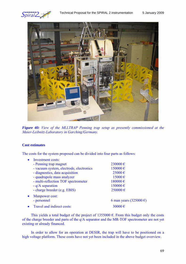
Technical Proposal for the SPIRAL 2 instrumentation 5 January 2009
69
Figure 40: View of the MLLTRAP Penning trap setup as presently commissioned at the Maier-Leibnitz-Laboratory in Garching/Germany. Cost estimates The costs for the system proposed can be divided into four parts as follows:
• Investment costs: - Penning trap magnet 230000 € - vacuum system, electrode, electronics 150000 € - diagnostics, data acquisition 25000 € - quadrupole mass analyzer 15000 € - multi-reflection TOF spectrometer 180000 € - q/A separation 150000 € - charge breeder (e.g. EBIS) 250000 €
• Manpower cost: - personnel 6 man years (325000 €)
• Travel and indirect costs: 30000 €
This yields a total budget of the project of 1355000 €. From this budget only the costs of the charge breeder and parts of the q/A separator and the MR-TOF spectrometer are not yet existing or already financed.
In order to allow for an operation at DESIR, the trap will have to be positioned on a
high voltage platform. These costs have not yet been included in the above budget overview.
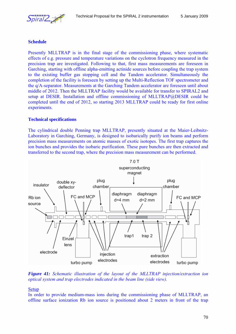
Technical Proposal for the SPIRAL 2 instrumentation 5 January 2009
70
Schedule
Presently MLLTRAP is in the final stage of the commissioning phase, where systematic effects of e.g. pressure and temperature variations on the cyclotron frequency measured in the precision trap are investigated. Following to that, first mass measurements are foreseen in Garching, starting with offline alpha-emitting actinide sources before coupling the trap system to the existing buffer gas stopping cell and the Tandem accelerator. Simultaneously the completion of the facility is foreseen by setting up the Multi-Reflection TOF spectrometer and the q/A-separator. Measurements at the Garching Tandem accelerator are foreseen until about middle of 2012. Then the MLLTRAP facility would be available for transfer to SPIRAL2 and setup at DESIR. Installation and offline commissioning of MLLTRAP@DESIR could be completed until the end of 2012, so starting 2013 MLLTRAP could be ready for first online experiments. Technical specifications The cylindrical double Penning trap MLLTRAP, presently situated at the Maier-Leibnitz-Laboratory in Garching, Germany, is designed to isobarically purify ion beams and perform precision mass measurements on atomic masses of exotic isotopes. The first trap captures the ion bunches and provides the isobaric purification. These pure bunches are then extracted and transferred to the second trap, where the precision mass measurement can be performed.
Figure 41: Schematic illustration of the layout of the MLLTRAP injection/extraction ion optical system and trap electrodes indicated in the beam line (side view). Setup In order to provide medium-mass ions during the commissioning phase of MLLTRAP, an offline surface ionization Rb ion source is positioned about 2 meters in front of the trap
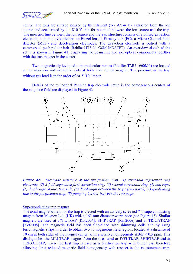
Technical Proposal for the SPIRAL 2 instrumentation 5 January 2009
71
center. The ions are surface ionized by the filament (5-7 A/2-4 V), extracted from the ion source and accelerated by a -1810 V transfer potential between the ion source and the trap. The injection line between the ion source and the trap structure consists of a pulsed extraction electrode, a double xy-deflector, an Einzel lens, a Faraday cup (FC), a Micro-Channel Plate detector (MCP) and deceleration electrodes. The extraction electrode is pulsed with a commercial push-pull-switch (Behlke HTS 31-GSM MOSFET). An overview sketch of the setup is shown in Figure 41, displaying the beam line and ion optical components together with the trap magnet in the center.
Two magnetically levitated turbomolecular pumps (Pfeiffer TMU 1600MP) are located at the injection and extraction side at both ends of the magnet. The pressure in the trap without gas load is in the order of ca. 5 .10-8 mbar.
Details of the cylindrical Penning trap electrode setup in the homogeneous centers of
the magnetic field are displayed in Figure 42.
Figure 42: Electrode structure of the purification trap: (1) eight-fold segmented ring electrode, (2) 2-fold segmented first correction ring, (3) second correction ring, (4) end caps, (5) diaphragm at injection side, (6) diaphragm between the traps (two parts), (7) gas-feeding line to the purification trap, (8) pumping barrier between the two traps. Superconducting trap magnet The axial magnetic field for the trap is created with an actively screened 7 T superconducting magnet from Magnex Ltd. (UK) with a 160-mm diameter warm bore (see Figure 43). Similar magnets are used at JYFLTRAP [Kol2004], SHIPTRAP [Rah2006] and at TRIGATRAP [Ket2008]. The magnetic field has been fine-tuned with shimming coils and by using ferromagnetic strips in order to obtain two homogeneous field regions located at a distance of 10 cm at both sides of the magnet center, with a relative homogeneity ΔB/B ≤ 0.3 ppm. This distinguishes the MLLTRAP magnet from the ones used at JYFLTRAP, SHIPTRAP and at TRIGATRAP, where the first trap is used as a purification trap with buffer gas, therefore allowing for a reduced magnetic field homogeneity with respect to the measurement trap.
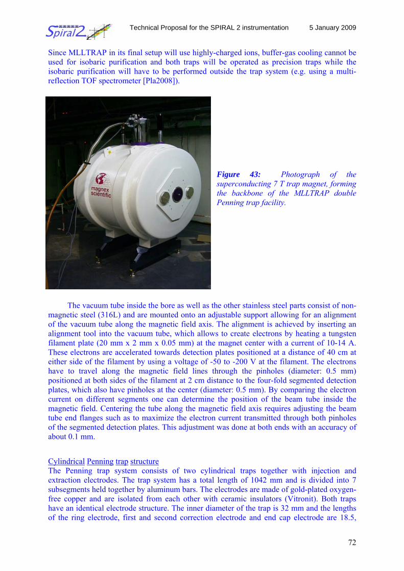
Technical Proposal for the SPIRAL 2 instrumentation 5 January 2009
72
Since MLLTRAP in its final setup will use highly-charged ions, buffer-gas cooling cannot be used for isobaric purification and both traps will be operated as precision traps while the isobaric purification will have to be performed outside the trap system (e.g. using a multi-reflection TOF spectrometer [Pla2008]).
Figure 43: Photograph of the superconducting 7 T trap magnet, forming the backbone of the MLLTRAP double Penning trap facility.
The vacuum tube inside the bore as well as the other stainless steel parts consist of non-
magnetic steel (316L) and are mounted onto an adjustable support allowing for an alignment of the vacuum tube along the magnetic field axis. The alignment is achieved by inserting an alignment tool into the vacuum tube, which allows to create electrons by heating a tungsten filament plate (20 mm x 2 mm x 0.05 mm) at the magnet center with a current of 10-14 A. These electrons are accelerated towards detection plates positioned at a distance of 40 cm at either side of the filament by using a voltage of -50 to -200 V at the filament. The electrons have to travel along the magnetic field lines through the pinholes (diameter: 0.5 mm) positioned at both sides of the filament at 2 cm distance to the four-fold segmented detection plates, which also have pinholes at the center (diameter: 0.5 mm). By comparing the electron current on different segments one can determine the position of the beam tube inside the magnetic field. Centering the tube along the magnetic field axis requires adjusting the beam tube end flanges such as to maximize the electron current transmitted through both pinholes of the segmented detection plates. This adjustment was done at both ends with an accuracy of about 0.1 mm. Cylindrical Penning trap structure The Penning trap system consists of two cylindrical traps together with injection and extraction electrodes. The trap system has a total length of 1042 mm and is divided into 7 subsegments held together by aluminum bars. The electrodes are made of gold-plated oxygen-free copper and are isolated from each other with ceramic insulators (Vitronit). Both traps have an identical electrode structure. The inner diameter of the trap is 32 mm and the lengths of the ring electrode, first and second correction electrode and end cap electrode are 18.5,
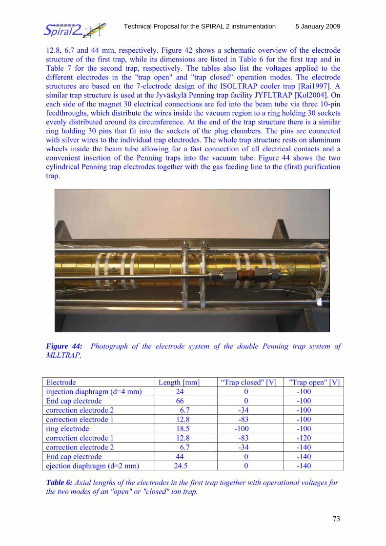
Technical Proposal for the SPIRAL 2 instrumentation 5 January 2009
73
12.8, 6.7 and 44 mm, respectively. Figure 42 shows a schematic overview of the electrode structure of the first trap, while its dimensions are listed in Table 6 for the first trap and in Table 7 for the second trap, respectively. The tables also list the voltages applied to the different electrodes in the "trap open" and "trap closed" operation modes. The electrode structures are based on the 7-electrode design of the ISOLTRAP cooler trap [Rai1997]. A similar trap structure is used at the Jyväskylä Penning trap facility JYFLTRAP [Kol2004]. On each side of the magnet 30 electrical connections are fed into the beam tube via three 10-pin feedthroughs, which distribute the wires inside the vacuum region to a ring holding 30 sockets evenly distributed around its circumference. At the end of the trap structure there is a similar ring holding 30 pins that fit into the sockets of the plug chambers. The pins are connected with silver wires to the individual trap electrodes. The whole trap structure rests on aluminum wheels inside the beam tube allowing for a fast connection of all electrical contacts and a convenient insertion of the Penning traps into the vacuum tube. Figure 44 shows the two cylindrical Penning trap electrodes together with the gas feeding line to the (first) purification trap.
Figure 44: Photograph of the electrode system of the double Penning trap system of MLLTRAP. Electrode Length [mm] “Trap closed" [V] "Trap open" [V]injection diaphragm (d=4 mm) 24 0 -100 End cap electrode 66 0 -100 correction electrode 2 6.7 -34 -100 correction electrode 1 12.8 -83 -100 ring electrode 18.5 -100 -100 correction electrode 1 12.8 -83 -120 correction electrode 2 6.7 -34 -140 End cap electrode 44 0 -140 ejection diaphragm (d=2 mm) 24.5 0 -140 Table 6: Axial lengths of the electrodes in the first trap together with operational voltages for the two modes of an "open" or "closed" ion trap.
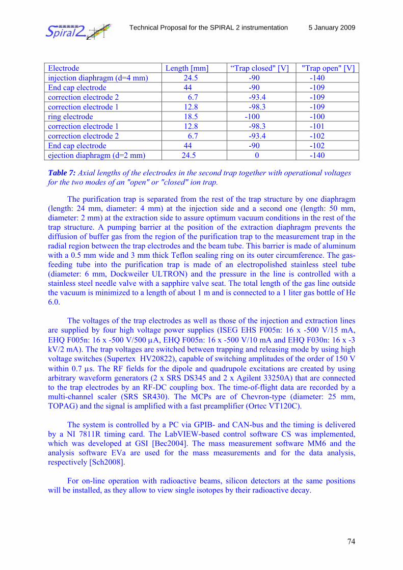
Technical Proposal for the SPIRAL 2 instrumentation 5 January 2009
74
Electrode Length [mm] “Trap closed" [V] "Trap open" [V]injection diaphragm (d=4 mm) 24.5 -90 -140 End cap electrode 44 -90 -109 correction electrode 2 6.7 -93.4 -109 correction electrode 1 12.8 -98.3 -109 ring electrode 18.5 -100 -100 correction electrode 1 12.8 -98.3 -101 correction electrode 2 6.7 -93.4 -102 End cap electrode 44 -90 -102 ejection diaphragm (d=2 mm) 24.5 0 -140 Table 7: Axial lengths of the electrodes in the second trap together with operational voltages for the two modes of an "open" or "closed" ion trap.
The purification trap is separated from the rest of the trap structure by one diaphragm (length: 24 mm, diameter: 4 mm) at the injection side and a second one (length: 50 mm, diameter: 2 mm) at the extraction side to assure optimum vacuum conditions in the rest of the trap structure. A pumping barrier at the position of the extraction diaphragm prevents the diffusion of buffer gas from the region of the purification trap to the measurement trap in the radial region between the trap electrodes and the beam tube. This barrier is made of aluminum with a 0.5 mm wide and 3 mm thick Teflon sealing ring on its outer circumference. The gas-feeding tube into the purification trap is made of an electropolished stainless steel tube (diameter: 6 mm, Dockweiler ULTRON) and the pressure in the line is controlled with a stainless steel needle valve with a sapphire valve seat. The total length of the gas line outside the vacuum is minimized to a length of about 1 m and is connected to a 1 liter gas bottle of He 6.0.
The voltages of the trap electrodes as well as those of the injection and extraction lines
are supplied by four high voltage power supplies (ISEG EHS F005n: 16 x -500 V/15 mA, EHQ F005n: 16 x -500 V/500 μA, EHQ F005n: 16 x -500 V/10 mA and EHQ F030n: 16 x -3 kV/2 mA). The trap voltages are switched between trapping and releasing mode by using high voltage switches (Supertex HV20822), capable of switching amplitudes of the order of 150 V within 0.7 μs. The RF fields for the dipole and quadrupole excitations are created by using arbitrary waveform generators (2 x SRS DS345 and 2 x Agilent 33250A) that are connected to the trap electrodes by an RF-DC coupling box. The time-of-flight data are recorded by a multi-channel scaler (SRS SR430). The MCPs are of Chevron-type (diameter: 25 mm, TOPAG) and the signal is amplified with a fast preamplifier (Ortec VT120C).
The system is controlled by a PC via GPIB- and CAN-bus and the timing is delivered
by a NI 7811R timing card. The LabVIEW-based control software CS was implemented, which was developed at GSI [Bec2004]. The mass measurement software MM6 and the analysis software EVa are used for the mass measurements and for the data analysis, respectively [Sch2008].
For on-line operation with radioactive beams, silicon detectors at the same positions
will be installed, as they allow to view single isotopes by their radioactive decay.
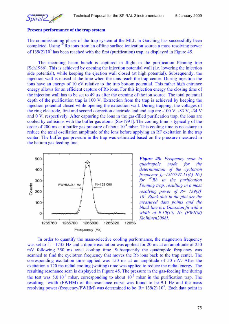
Technical Proposal for the SPIRAL 2 instrumentation 5 January 2009
75
Present performance of the trap system The commissioning phase of the trap system at the MLL in Garching has successfully been completed. Using 85Rb ions from an offline surface ionization source a mass resolving power of 139(2).103 has been reached with the first (purification) trap, as displayed in Figure 45.
The incoming beam bunch is captured in flight in the purification Penning trap [Sch1986]. This is achieved by opening the injection potential wall (i.e. lowering the injection side potential), while keeping the ejection wall closed (at high potential). Subsequently, the injection wall is closed at the time when the ions reach the trap center. During injection the ions have an energy of 10 eV relative to the trap bottom potential. This rather high entrance energy allows for an efficient capture of Rb ions. For this injection energy the closing time of the injection wall has to be set to 49 μs after the opening of the ion source. The total potential depth of the purification trap is 100 V. Extraction from the trap is achieved by keeping the injection potential closed while opening the extraction wall. During trapping, the voltages of the ring electrode, first and second correction electrode and end cap are -100 V, -83 V, -34 V and 0 V, respectively. After capturing the ions in the gas-filled purification trap, the ions are cooled by collisions with the buffer gas atoms [Sav1991]. The cooling time is typically of the order of 200 ms at a buffer gas pressure of about 10-4 mbar. This cooling time is necessary to reduce the axial oscillation amplitude of the ions before applying an RF excitation in the trap center. The buffer gas pressure in the trap was estimated based on the pressure measured in the helium gas feeding line.
Figure 45: Frequency scan in quadrupole mode for the determination of the cyclotron frequency fc=1265797.11(6) Hz) for 85Rb in the purification Penning trap, resulting in a mass resolving power of R= 139(2). 103. Black dots in the plot are the measured data points and the black line is a Gaussian fit with a width of 9.10(15) Hz (FWHM) [kolhinen2008].
In order to quantify the mass-selective cooling performance, the magnetron frequency was set to f - =1735 Hz and a dipole excitation was applied for 20 ms at an amplitude of 250 mV following 350 ms axial cooling time. Subsequently the quadrupole frequency was scanned to find the cyclotron frequency that moves the Rb ions back to the trap center. The corresponding excitation time applied was 150 ms at an amplitude of 50 mV. After the excitation a 120 ms radial cooling (waiting) time was applied to reduce the radial energy. The resulting resonance scan is displayed in Figure 45. The pressure in the gas-feeding line during the test was 5.0.10-4 mbar, corresponding to about 10-5 mbar in the purification trap. The resulting width (FWHM) of the resonance curve was found to be 9.1 Hz and the mass resolving power (frequency/FWHM) was determined to be R= 139(2) 103. Each data point in
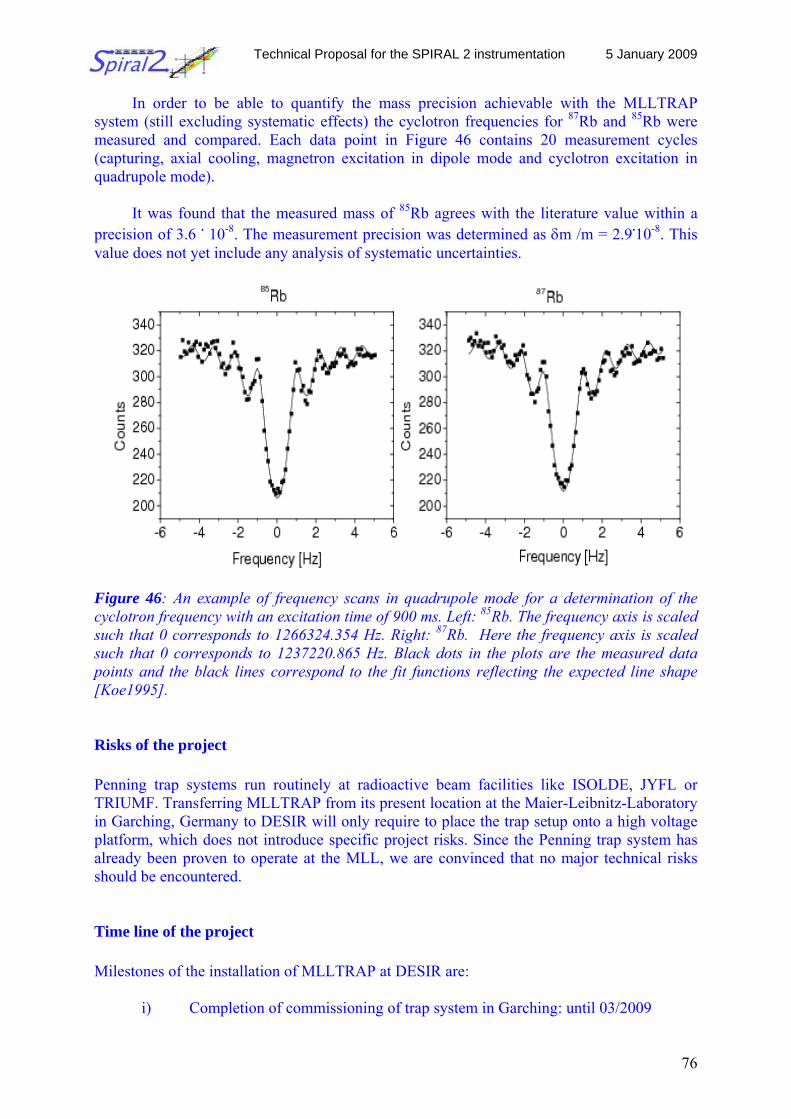
Technical Proposal for the SPIRAL 2 instrumentation 5 January 2009
76
In order to be able to quantify the mass precision achievable with the MLLTRAP system (still excluding systematic effects) the cyclotron frequencies for 87Rb and 85Rb were measured and compared. Each data point in Figure 46 contains 20 measurement cycles (capturing, axial cooling, magnetron excitation in dipole mode and cyclotron excitation in quadrupole mode).
It was found that the measured mass of 85Rb agrees with the literature value within a
precision of 3.6 . 10-8. The measurement precision was determined as δm /m = 2.9.10-8. This value does not yet include any analysis of systematic uncertainties.
Figure 46: An example of frequency scans in quadrupole mode for a determination of the cyclotron frequency with an excitation time of 900 ms. Left: 85Rb. The frequency axis is scaled such that 0 corresponds to 1266324.354 Hz. Right: 87Rb. Here the frequency axis is scaled such that 0 corresponds to 1237220.865 Hz. Black dots in the plots are the measured data points and the black lines correspond to the fit functions reflecting the expected line shape [Koe1995]. Risks of the project Penning trap systems run routinely at radioactive beam facilities like ISOLDE, JYFL or TRIUMF. Transferring MLLTRAP from its present location at the Maier-Leibnitz-Laboratory in Garching, Germany to DESIR will only require to place the trap setup onto a high voltage platform, which does not introduce specific project risks. Since the Penning trap system has already been proven to operate at the MLL, we are convinced that no major technical risks should be encountered. Time line of the project Milestones of the installation of MLLTRAP at DESIR are:
i) Completion of commissioning of trap system in Garching: until 03/2009
Technical Proposal for the SPIRAL 2 instrumentation 5 January 2009
77
ii) Setup of MR-TOF spectrometer: until 06/2010 iii) Setup of q/A separator: until 12/2010 iv) Offline and online mass measurements at Garching: until 06/2012 v) Dismounting, transport of MLLTRAP from Munich to GANIL: until 08/2012 vi) Setup of high voltage platform at DESIR: until 08/2012 vii) Mounting and commissioning of MLLTRAP: until 12/2012 viii) first on-line experiment: 01/2013
Beam requirements Off-line tests: A surface ionization source delivering stable ion species is available to test the performance of the trap system and the other components of the setup. In the future a carbon cluster ion source may be considered as well to be set up as reference ion source for highly accurate mass measurements. Beam quality: For efficient injection into the Penning trap system, a beam emittance of the order of 2-3 π mm mrad and an energy dispersion of about 1 eV are needed. These requirements will be fulfilled with the RFQ cooler and buncher of DESIR. Beam intensities: For mass measurements in the Penning trap system an ion rate of at least 1-2 ions per second can realistically be used for accurate mass measurements, which will especially be of interest considering the low production intensities of heavy ion species delivered from the S3 separator. References [DESIR] http://www.ganil.fr/spiral2/files/LoIs_SP2_final/LoI_SP2_1_DESIR_final.pdf [S3] http://www-dapnia.cea.fr/Phocea/Vie_des_labos/Ast/ast_technique.php?id_ast=943 [Kol2008] V.S. Kolhinen et al., Nucl. Instr. and Meth. B 266 (2008) 4547 [Kol2008a] V.S. Kolhinen et al., accepted for publication in Nucl. Instr. and Meth. A (2008) [Har2005] J.C. Hardy, I.S. Towner, Phys. Rev. C 71,(2005) 05550 [Bla2006] K. Blaum, Phys. Rep. 425 (2006) 1 [Kol2004] V.S. Kolhinen et al., Nucl. Instr. Meth. A 528 (2004) 776 [Rah2006] S. Rahaman et al., Int. J. Mass Spectrom. 251 (2006) 146 [Ket2008] J. Ketelaer et al., Nucl. Instr. Meth. A 594 (2008) 162 [Pla2008] W.R. Plass et al., Nucl. Instr. Meth. B 266 (2008) 4560 [Rai1997] H. Raimbault-Hartmann et al., Nucl. Instr. Meth. B 126 (1997) 378 [Bec2004] D. Beck et al., Nucl. Instr. and Meth. A 527 (2004) 567 [Sch2008] S. Schwarz, private communication [Koe1995] M. König et al., Int. J. Mass. Spectrom. 142 (1995) 95 [Sch1986] H. Schnatz et al., Nucl. Instr. Meth. A 251 (1986) 17 [Sav1991] G. Savard et al., Phys. Lett. A 158 (1991) 247 [Lak1992] A. Lakatos, Diploma thesis, University of Frankfurt, unpublished
Technical Proposal for the SPIRAL 2 instrumentation 5 January 2009
78
2.2.8 The atomic trapping facility Scientific coordinator: H. Wilschut, KVI Groningen
Introduction and physics case Atomic trapping of radioactive atoms allows one to perform precision measurements by which one can search for new physics, i.e. to set new limits on the validity of the Standard Model. The decay of the trapped atom results in a recoiling nucleus that can be observed in a reaction microscope. Detecting also the β-particle makes the decay kinematically complete. In β-neutrino correlations one may search for scalar (S) and tensor (T) contributions to the vector and axial-vector (V-A) structure of the Weak Interaction. When the sample can be polarized the β-decay correlation )( νppJ e ×⋅ can be measured, which is odd under time reversal [Sev06]. For the latter studies mixed Gamow-Teller/Fermi transitions, in particular in mirror nuclei, are most desirable candidates. The interest in measuring correlations in mirror nuclei for determining the quark-mixing element Vud is outlined in the next section.
Atomic trapping is also relevant for measuring atomic parity non-conservation (APNC) [Hax01]. An interesting feature of SPIRAL2 is the copious production of neutron rich Cs isotopes. The fundamental measurement of the weak charge has been performed most accurately by Wieman and co-workers for 133Cs, i.e. the only stable isotope of Cs. The comparison to the Standard Model value of the weak charge required both a correct atomic and nuclear structure descriptions. Alternative techniques to the Boulder measurement have been suggested by Bouchiat [Bou08] and would require atomic trapping of Cs. This is technically relatively easy as only solid state lasers are required. At SPIRAL2 the systematics of the weak charge (spin independent APNC) and the anapole moment (spin dependent) would become feasible for a very long isotopic chain.
To obtain atoms in a trap, a conversion of ions to atoms is made in a collector trap with
a hot neutralizer. An intense low-energy beam of ions as can be provided by DESIR is for all atomic trapping scenarios an essential starting point. Key experiments Experiments in the electro-weak sector (β-decay correlations) are increasingly accurate. In particular, for APNC new measuring concepts are suggested. Building on the high the intensity and availabilities of isotopic species SPIRAL2 + DESIR can provide will allow systematic research in reducing the current limits on “new physics”. In all cases use of alkaline or earth-alkaline elements is preferred. The experimental setup The setup considered is currently used at KVI for β-decay correlations. The basic concept is a dual Magneto-Optical Trap (MOT), which allows accumulating radioactive ions, neutralizing and transferring them into an atomic trap where the actual measurement can take place.
Technical Proposal for the SPIRAL 2 instrumentation 5 January 2009
79
An optical laboratory was set up featuring dye laser, Ti:sapphire and diode laser light. The laboratory is equipped with the necessary laser beam diagnostics equipment. The laser facility provides light at many wavelengths. The facility focuses on flexibility to provide other wavelengths when it is required by a particular experiment. This is achieved by employing wide range tunable dye laser or Ti:sapphire laser systems, diode laser systems and second harmonic generation. The technology of building diode laser systems was chosen because of their good performance at low costs. Furthermore, the range of available wavelengths for laser diodes is constantly increasing. The absolute frequencies of the lasers can be determined with an uncertainty of 10-6 with commercial wavelength meters or to 10-9 by atomic (Na, Ba) or molecular spectroscopy (127I2 and 130Te2). The lasers can be stabilized with developed electronic servo loops to such absolute references. The achieved accuracy is sufficient for most applications. The lasers and optical technology are state of the art. Therefore we expect that the investments in lasers and laser laboratories can be exploited well into the DESIR era. However, additional investments would naturally come with new experiments that we would like to start.
Magneto-Optical Traps Magneto-optical traps (MOTs) are operated by our group on Na, Ca and Ba. At present a MOT setup for Na is installed at the end of the TRIμP Low Energy Beam Line at KVI. Successful trapping of Na isotopes has been demonstrated. Present work includes efficiency enhancement by studies of the neutralization and preparation of the laser systems for reliable and stable operation at the frequencies of 21Na. This is in preparation of a β−ν correlation measurement in the β-decay of the isotope. This aspect can be carried over into the DESIR environment. Experimental Station For the β-decay experiments a reaction microscope was constructed which draws in its design from the device employed in the collision charge transfer experiments in the KVI atomic physics group. Further a position sensitive scintillation β telescope was developed. This instrumentation is ready for β-decay experiments. Complementarities with other DESIR experimental devices The physics aims are complementary to those of LPCTrap (weak decays) and with precision measurements of lifetimes, branching ratios and Q-values from BESTIOL and the MLLTrap. Cost estimates Estimated costs are as follows: Multipurpose laser systems (if new) 200 k€ Vacuum chambers and equipment 100 k€ Optics including modulators 100 k€ Power supplies, electronics and diagnostics 100 k€ Total budget of the project 500 k€
Technical Proposal for the SPIRAL 2 instrumentation 5 January 2009
80
Schedule The Na MOT system is fully operational at KVI. Adapting to other elements and isotopes depends on the specific atomic structure and range of isotopes and may require up to 2 man-years. Installing the basic working platform will cost 2 man-years. Technical specifications A trapping efficiency in the collector MOT of 1% is maximally feasible, with transfer to the detection MOT of at least 105 atoms/s. The lifetime of the atoms in the trap is limited by residual vacuum and can exceed several 10 seconds. The current detection MOT has an open geometry of the trap and offers a large solid angle for the detectors. A precision experiment requires measuring at least 108 decay events. Beam requirements Off-line tests: Stable elements with the same energy as the radioactive nucleus of interest should be produced to adjust the optical parameters of the whole setup. Beam quality: The primary beam should be focused through a minimal opening on the neutralizer in the collector MOT. A beam emittance of the order of 10 mm mrad is therefore desirable to minimize losses at this stage. These requirements will be fulfilled with the GPIB of DESIR. Beam intensities: To perform the experiments described above, a beam intensity of the ions of interest of at least 107 ions/s is required. References [Sev06] N. Severijns et al., Rev. Mod. Phys. 78 (2006) 91 [Hax01] W.C. Haxton, C.E. Wieman, Ann. Rev. of Nucl. and Part. Science 51 (2001) 261 [Bou08] M.A. Bouchiat, Phys. Rev. Lett. 100 (2008) 123003
2.2.9 The LPCTrap setup Scientific coordinator: E. Liénard & O. Naviliat-Cuncic, LPC Caen Introduction and physics case Precision measurements performed at low energies are a sensitive way to test the assumptions of the electroweak standard model [Sev06]. In particular, the measurement of the β–ν angular correlation coefficient in nuclear β-decay is motivated by the search for exotic interactions as signatures of physics beyond the SM. Pure transitions (Fermi or Gamow-Teller) are of particular interest because the correlation coefficients are sensitive only to one exotic coupling in each case allowing unambiguous tests. The continuous improvements in the
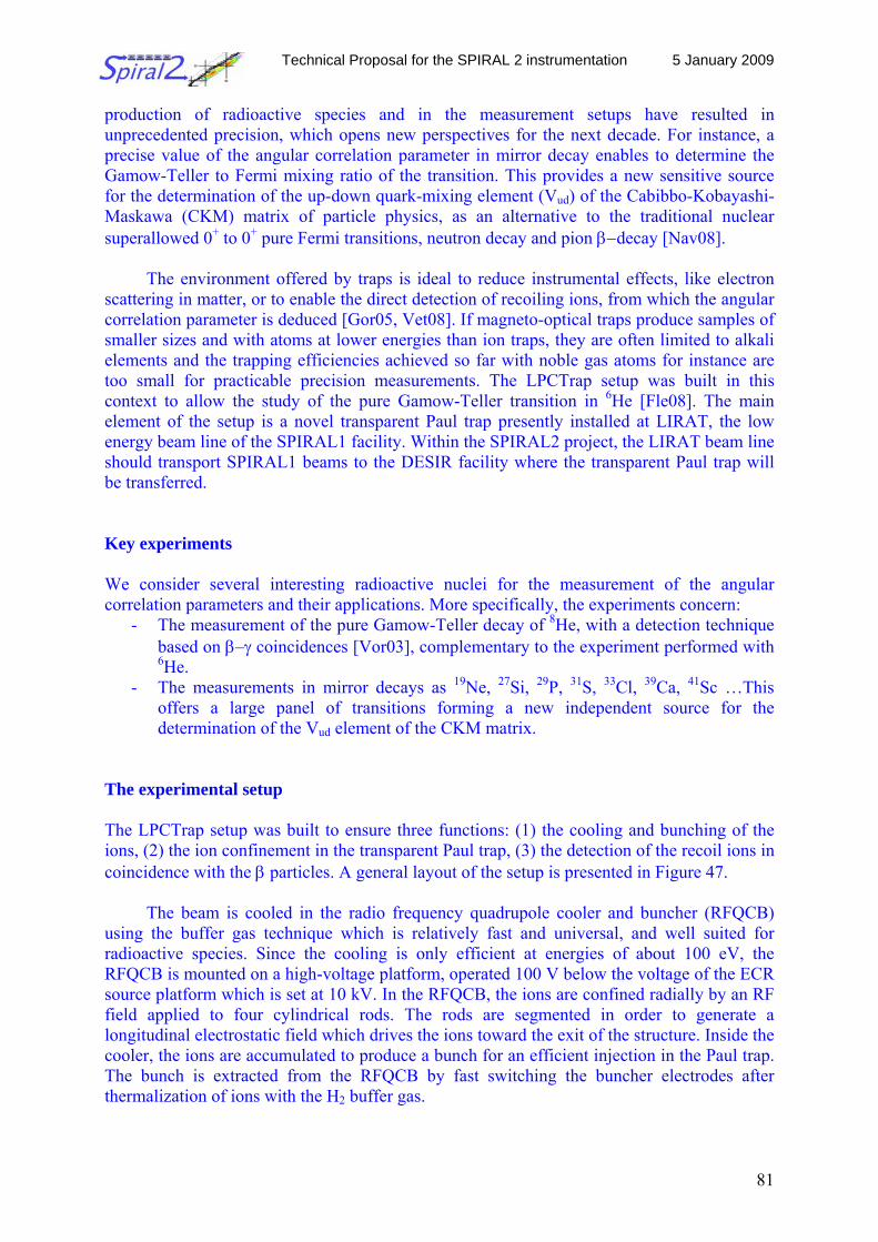
Technical Proposal for the SPIRAL 2 instrumentation 5 January 2009
81
production of radioactive species and in the measurement setups have resulted in unprecedented precision, which opens new perspectives for the next decade. For instance, a precise value of the angular correlation parameter in mirror decay enables to determine the Gamow-Teller to Fermi mixing ratio of the transition. This provides a new sensitive source for the determination of the up-down quark-mixing element (Vud) of the Cabibbo-Kobayashi-Maskawa (CKM) matrix of particle physics, as an alternative to the traditional nuclear superallowed 0+ to 0+ pure Fermi transitions, neutron decay and pion β−decay [Nav08].
The environment offered by traps is ideal to reduce instrumental effects, like electron scattering in matter, or to enable the direct detection of recoiling ions, from which the angular correlation parameter is deduced [Gor05, Vet08]. If magneto-optical traps produce samples of smaller sizes and with atoms at lower energies than ion traps, they are often limited to alkali elements and the trapping efficiencies achieved so far with noble gas atoms for instance are too small for practicable precision measurements. The LPCTrap setup was built in this context to allow the study of the pure Gamow-Teller transition in 6He [Fle08]. The main element of the setup is a novel transparent Paul trap presently installed at LIRAT, the low energy beam line of the SPIRAL1 facility. Within the SPIRAL2 project, the LIRAT beam line should transport SPIRAL1 beams to the DESIR facility where the transparent Paul trap will be transferred. Key experiments We consider several interesting radioactive nuclei for the measurement of the angular correlation parameters and their applications. More specifically, the experiments concern:
- The measurement of the pure Gamow-Teller decay of 8He, with a detection technique based on β–γ coincidences [Vor03], complementary to the experiment performed with 6He.
- The measurements in mirror decays as 19Ne, 27Si, 29P, 31S, 33Cl, 39Ca, 41Sc …This offers a large panel of transitions forming a new independent source for the determination of the Vud element of the CKM matrix.
The experimental setup The LPCTrap setup was built to ensure three functions: (1) the cooling and bunching of the ions, (2) the ion confinement in the transparent Paul trap, (3) the detection of the recoil ions in coincidence with the β particles. A general layout of the setup is presented in Figure 47.
The beam is cooled in the radio frequency quadrupole cooler and buncher (RFQCB) using the buffer gas technique which is relatively fast and universal, and well suited for radioactive species. Since the cooling is only efficient at energies of about 100 eV, the RFQCB is mounted on a high-voltage platform, operated 100 V below the voltage of the ECR source platform which is set at 10 kV. In the RFQCB, the ions are confined radially by an RF field applied to four cylindrical rods. The rods are segmented in order to generate a longitudinal electrostatic field which drives the ions toward the exit of the structure. Inside the cooler, the ions are accumulated to produce a bunch for an efficient injection in the Paul trap. The bunch is extracted from the RFQCB by fast switching the buncher electrodes after thermalization of ions with the H2 buffer gas.
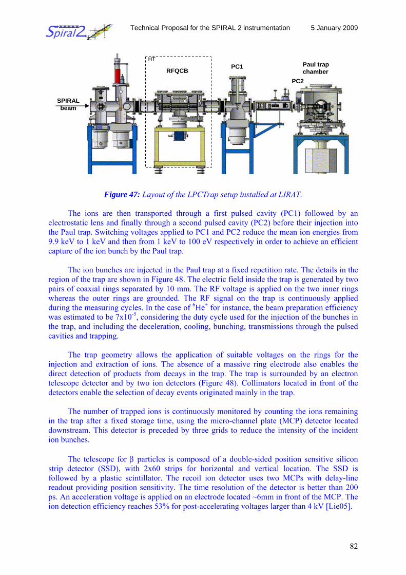
Technical Proposal for the SPIRAL 2 instrumentation 5 January 2009
82
Figure 47: Layout of the LPCTrap setup installed at LIRAT.
The ions are then transported through a first pulsed cavity (PC1) followed by an electrostatic lens and finally through a second pulsed cavity (PC2) before their injection into the Paul trap. Switching voltages applied to PC1 and PC2 reduce the mean ion energies from 9.9 keV to 1 keV and then from 1 keV to 100 eV respectively in order to achieve an efficient capture of the ion bunch by the Paul trap.
The ion bunches are injected in the Paul trap at a fixed repetition rate. The details in the region of the trap are shown in Figure 48. The electric field inside the trap is generated by two pairs of coaxial rings separated by 10 mm. The RF voltage is applied on the two inner rings whereas the outer rings are grounded. The RF signal on the trap is continuously applied during the measuring cycles. In the case of 6He+ for instance, the beam preparation efficiency was estimated to be 7x10⁻⁵, considering the duty cycle used for the injection of the bunches in the trap, and including the deceleration, cooling, bunching, transmissions through the pulsed cavities and trapping.
The trap geometry allows the application of suitable voltages on the rings for the injection and extraction of ions. The absence of a massive ring electrode also enables the direct detection of products from decays in the trap. The trap is surrounded by an electron telescope detector and by two ion detectors (Figure 48). Collimators located in front of the detectors enable the selection of decay events originated mainly in the trap.
The number of trapped ions is continuously monitored by counting the ions remaining
in the trap after a fixed storage time, using the micro-channel plate (MCP) detector located downstream. This detector is preceded by three grids to reduce the intensity of the incident ion bunches.
The telescope for β particles is composed of a double-sided position sensitive silicon
strip detector (SSD), with 2x60 strips for horizontal and vertical location. The SSD is followed by a plastic scintillator. The recoil ion detector uses two MCPs with delay-line readout providing position sensitivity. The time resolution of the detector is better than 200 ps. An acceleration voltage is applied on an electrode located ~6mm in front of the MCP. The ion detection efficiency reaches 53% for post-accelerating voltages larger than 4 kV [Lie05].
RFQCB PC1 Paul trap chamber
SPIRAL beam
HT
PC2
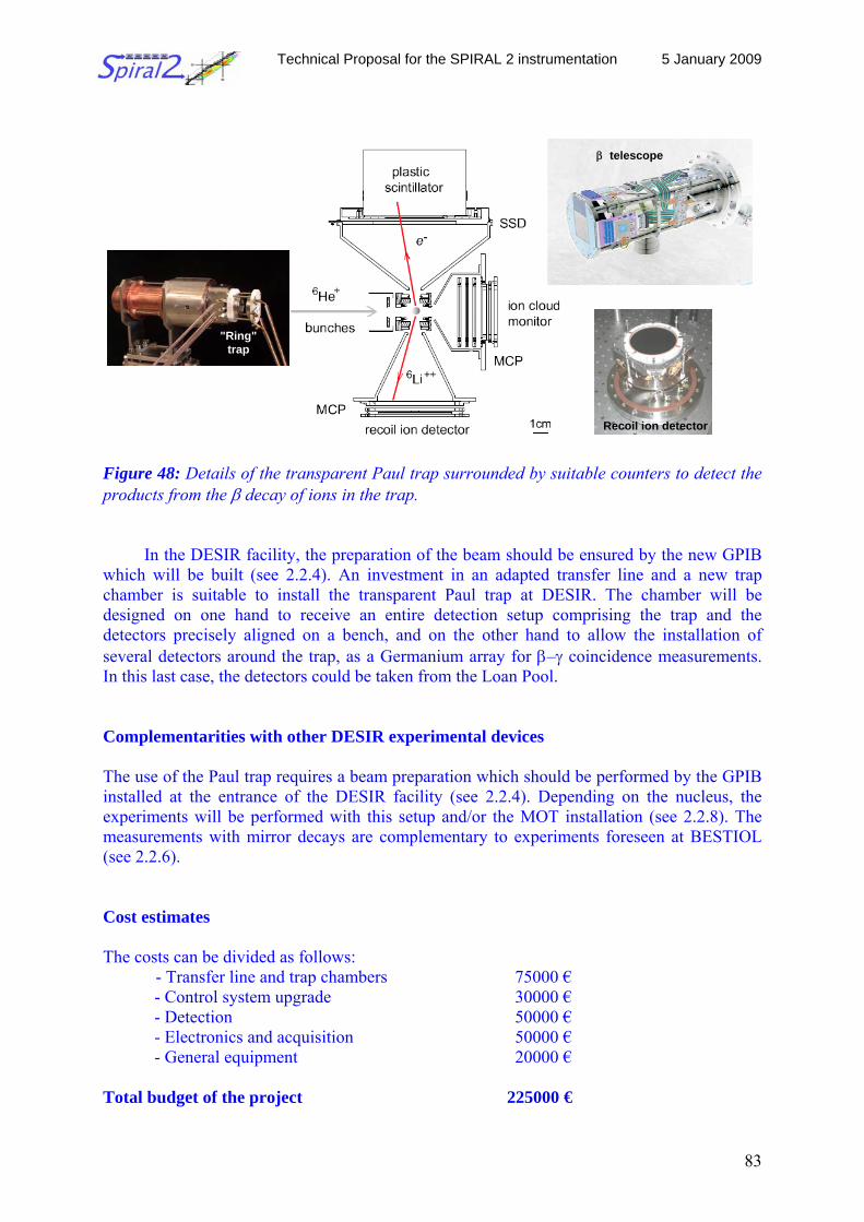
Technical Proposal for the SPIRAL 2 instrumentation 5 January 2009
83
Figure 48: Details of the transparent Paul trap surrounded by suitable counters to detect the products from the β decay of ions in the trap.
In the DESIR facility, the preparation of the beam should be ensured by the new GPIB which will be built (see 2.2.4). An investment in an adapted transfer line and a new trap chamber is suitable to install the transparent Paul trap at DESIR. The chamber will be designed on one hand to receive an entire detection setup comprising the trap and the detectors precisely aligned on a bench, and on the other hand to allow the installation of several detectors around the trap, as a Germanium array for β–γ coincidence measurements. In this last case, the detectors could be taken from the Loan Pool. Complementarities with other DESIR experimental devices The use of the Paul trap requires a beam preparation which should be performed by the GPIB installed at the entrance of the DESIR facility (see 2.2.4). Depending on the nucleus, the experiments will be performed with this setup and/or the MOT installation (see 2.2.8). The measurements with mirror decays are complementary to experiments foreseen at BESTIOL (see 2.2.6). Cost estimates The costs can be divided as follows: - Transfer line and trap chambers 75000 € - Control system upgrade 30000 € - Detection 50000 € - Electronics and acquisition 50000 € - General equipment 20000 € Total budget of the project 225000 €
"Ring" trap
β telescope
Recoil ion detector
Technical Proposal for the SPIRAL 2 instrumentation 5 January 2009
84
Schedule
The LPCTrap setup is operational at LIRAT and could be used in the present configuration at the DESIR facility. The design and building of the new chambers could be achieved within 2 years.
Technical specifications The Paul trap performances were measured with 6Li1+ and 6He1+ ions [Duv08]. Roughly, a trapping efficiency of 20% has been reached, with a capacity higher than 105 ions essentially limited by the beam preparation line. A cloud size of about 1mm was obtained, with a mean T° of about 0.1 eV. The lifetime of the ions in the trap reaches several hundred of ms.
The open geometry of the trap offers a large solid angle for the detectors. With the whole setup described above, 4 106 coincidences between the β's and recoiling ions were collected during one week of data taking with an 6He1+ beam intensity of 2 108 pps delivered by LIRAT. Beam requirements Off-line tests: Stable elements with the same mass and energy as the radioactive nucleus of interest should be produced to adjust the main parameters of the whole setup. Beam quality: For efficient injection into the Paul trap, a beam emittance of the order of 2-3 π mm mrad and energy dispersion of about 1 eV are needed. These requirements will be fulfilled with the GPIB of DESIR. Beam intensities: To perform the experiments described above, beam intensities of the ions of interest of at least 107 are required. References [Sev06] N. Severijns et al., Rev. Mod. Phys. 78 (2006) 91 [Nav08] O. Naviliat et N. Severijns, arXiv:0809.0994 [Gor05] A. Gorelov et al., Phys. Rev. Lett. 94 (2005) 142501 [Vet08] P.A. Vetter et al., Phys. Rev. C 77 (2008) 035502 [Fle08] X. Flechard et al., Phys. Rev. Lett. 101 (2008) 212504 [Vor03] V. Vorobel et al., Eur. Phys. J. A 16 (2003) 139 [Lie05] E. Liénard et al., Nucl. Instrum. Meth. Phys. Res. A 551 (2005) 375 [Duv08] F. Duval et al., Nucl. Instrum. Meth. Phys. Res. B 266 (2008) 4537
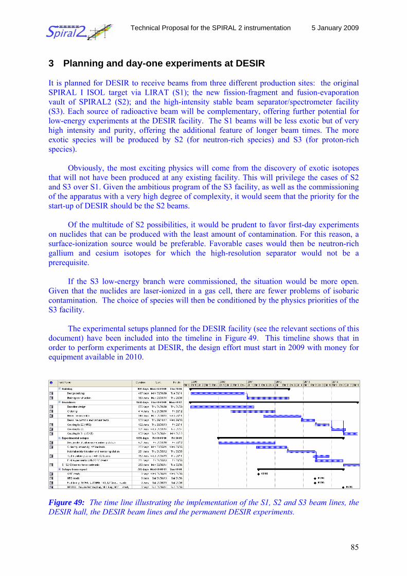
Technical Proposal for the SPIRAL 2 instrumentation 5 January 2009
85
3 Planning and day-one experiments at DESIR It is planned for DESIR to receive beams from three different production sites: the original SPIRAL I ISOL target via LIRAT (S1); the new fission-fragment and fusion-evaporation vault of SPIRAL2 (S2); and the high-intensity stable beam separator/spectrometer facility (S3). Each source of radioactive beam will be complementary, offering further potential for low-energy experiments at the DESIR facility. The S1 beams will be less exotic but of very high intensity and purity, offering the additional feature of longer beam times. The more exotic species will be produced by S2 (for neutron-rich species) and S3 (for proton-rich species).
Obviously, the most exciting physics will come from the discovery of exotic isotopes that will not have been produced at any existing facility. This will privilege the cases of S2 and S3 over S1. Given the ambitious program of the S3 facility, as well as the commissioning of the apparatus with a very high degree of complexity, it would seem that the priority for the start-up of DESIR should be the S2 beams.
Of the multitude of S2 possibilities, it would be prudent to favor first-day experiments
on nuclides that can be produced with the least amount of contamination. For this reason, a surface-ionization source would be preferable. Favorable cases would then be neutron-rich gallium and cesium isotopes for which the high-resolution separator would not be a prerequisite.
If the S3 low-energy branch were commissioned, the situation would be more open.
Given that the nuclides are laser-ionized in a gas cell, there are fewer problems of isobaric contamination. The choice of species will then be conditioned by the physics priorities of the S3 facility.
The experimental setups planned for the DESIR facility (see the relevant sections of this
document) have been included into the timeline in Figure 49. This timeline shows that in order to perform experiments at DESIR, the design effort must start in 2009 with money for equipment available in 2010.
Figure 49: The time line illustrating the implementation of the S1, S2 and S3 beam lines, the DESIR hall, the DESIR beam lines and the permanent DESIR experiments.
Technical Proposal for the SPIRAL 2 instrumentation 5 January 2009
86
As to which experiments should be performed first, it is logical to foresee nuclear spectroscopy as the first priority. A relatively robust spectroscopy experiment would also serve as a good method for benchmarking the S2 production performance. Nuclear spectroscopy can be setup without any need of prior commissioning, unlike more complicated apparatus such as laser spectroscopy or Penning traps.
The minimum configuration for the DESIR beam lines would include a stable-ion source (in order to commission the beam lines independently) and a three-way switchyard in order to set up one primary experiment, one back-up experiment, and to have room to accommodate existing apparatus if it is ready. It is of course preferable to construct several beam lines sooner since it makes the installation of apparatus much more straightforward. 4 Safety issues and proposed solutions
Responsible from DESIR: J.-C.Thomas 4.1 Generalities
The DESIR building houses beam lines delivering radioactive ions to experimental equipments. Radioactive ion beams are of low energy (from 10 to 60 kV) and they originate from three different installations: S3, the SPIRAL2 production building (1+ beam line) and SPIRAL1.
The safety issues depend on the RIB characteristics: S3 will mainly deliver to DESIR short lived neutron-deficient ions with masses A ~ 100 and with maximum intensities of about 106 pps. Accordingly, the low energy branch of S3 where RIB will be prepared for DESIR will be operated as a controlled green zone (radioprotection classification based on ambient Equivalent Dose Rate).
. The SPIRAL1 low-energy beam line (LIRAT) will mainly deliver light and short lived
ions with intensities varying from a few pps for the most exotic ones up to 109 pps. An existing identification station called IBE is located at the beginning of the LIRAT line and will allow the characterization of the SPIRAL1 low-energy RIB before they are sent to DESIR.
The SPIRAL2 production building will mainly deliver RIB produced in the neutron-
induced fission of 238U targets and proton-rich nuclei from fusion-evaporation reactions, thus leading to a large variety of radioactive ions. These RIB will be most of the time mass separated by means of the RFQ-Cooler and HRS ensemble located in the production building. A 1+ identification station located after of the HRS will allow to some extent the measurement of the isotopic composition of the mass separated beams. Although RIB intensities as high as 1012 pps are expected for some isotopes, most of the DESIR experiments require RIB intensities lower than 106 pps.
Due to the large number of experimental setups and their relative complexity requiring
long preparatory phases, the main user requirement is to allow the presence of authorized people inside the building working on their own setup while the beam is delivered to another setup. The building will therefore be run as a green zone with controlled access. This
Technical Proposal for the SPIRAL 2 instrumentation 5 January 2009
87
requirement does not apply to the three beam transport areas, the interfaces, delivering the RIB to the DESIR building: Access to these areas will be forbidden during the beam delivery.
4.2 Safety requirements Taking into account what precedes, the safety requirements are the following:
i) Access to the DESIR building must be controlled and granted to authorized people only.
ii) In normal running conditions, the radiation exposition of people working in the
building should be limited to the following dose rates (DeD), compatible with a green zone: - DeD < 25 µSv/h anywhere in the building; - Annual dose < 2 mSv/y per worker; - DeD < 7,5 µSv/h at permanent (few hours a day) working places - DeD < 100 µSv/h at temporary (few minutes) working places - DeD < 2 mSv/h locally (shielded and forbidden area)
iii) In normal running conditions, the full activity originating from the use of RIB
must be known at any time and must be confined inside the beam pipes and vacuum chambers. In particular, the beam induced activity outside these confining devices must be close to 0 LPCA (0 Bq/m3 in air) and the global contamination in the building should not exceed 0.4 Bq/cm2 (on any surface), compatible with a containment class C1, according to the norm ISO 17 873.
iv) In case a confining device fails (accidental scenario), the presumably released
activity must not exceed 1 LPCA (in air) and 0.4 Bq/cm² (on any surface) inside the DESIR building. The impact of such an accident on the environment (outside the GANIL INB) must be lower than 50 µSv.
Safety requirements are currently being listed in more details in the framework of the
SPIRAL2 - Phase 2 building program and they will be defined in the DESIR safety report to be released by the end of 2009. 4.3 Proposed solutions 4.3.1 Generalities
The aim of the proposed solutions is to guarantee that the main safety requirements listed in the section 4.2. are fulfilled. They need to be further studied and validated. 4.3.2 Access to DESIR Access will be granted to authorized people only by means of badges (safety courses to be followed). In order to control access to the DESIR building, only two accesses will be proposed: A people and small equipment access (2*2 m2) at the entrance of the building and a truck access (5*5 m2) on one side of the building (see Figure 6). Both areas will be divided into a controlled zone (contamination of the full body and of equipments) and in a pressurized
Technical Proposal for the SPIRAL 2 instrumentation 5 January 2009
88
zone (see next section). Clearance to exit the DESIR building will only be provided if there is no contamination of people nor equipments. Similar principles apply to the access to the research reactor of the ILL institute at Grenoble. The same technical solutions may be adopted. 4.3.3 Activity confinement The RIB induced activity must be confined at any time in the beam lines or in the experimental setups. Therefore, a good vacuum must be ensured in the confining equipment while the beam is delivered. The pressure will be controlled on-line and the associated monitors will allow stopping the beam delivery to the DESIR building if vacuum levels are not maintained all along the beam line. All gases extracted from the beam lines and the experimental equipment (in operation as well as during aeration sequences) will be temporarily stored in dedicated storage devices (balloons, bottles,…) located inside the DESIR building. They will be released via the SPIRAL2 production building chimney after cooling.
Depending on the lifetime and the volatility of the radioactive ions used during DESIR
runs and taking into account the radiological inventory, specific procedures may be applied to dismantle beam lines and experimental equipment in order to avoid the release of a substantial amount of activity in the building. As an example, the isolation of Faraday cups and implantation chambers by means of double sets of valves may be considered in order to keep them at a low pressure when they are removed from the beam lines. Confining valves would be dismantled after the ensembles are set inside dedicated maintenance boxes with appropriate ventilation.
In case of accidental vacuum breakdown, the activity presumably released in the
surrounding of the deficient equipment has to be lower than 1 LPCA, limiting the contamination risks by inhalation. To further ensure that the released activity is of no impact on the environment of the DESIR building, a low depression will be maintained in the building while the beam is delivered.
In operation, the access to the transport line sections from any of the RIB production
stations (S1, S2, or S3) to the DESIR experimental area will be forbidden. 4.3.4 Running conditions 4.3.4.1 Generalities In operation, the delivery of RIB to an experimental setup will be notified to the DESIR users by means of neon signs. The same stands for any other hazard associated with the operation of equipment presenting some risks (use of explosive gases in the RFQ cooler, laser light, liquid nitrogen in confined areas,...).
In addition to the pressure monitoring devices mentioned previously, radiation detection
systems located close to the beam path will allow stopping the beam delivery to the DESIR building if dose rate thresholds are reached. The low depression of the building will also be required to run an experiment in DESIR.
Technical Proposal for the SPIRAL 2 instrumentation 5 January 2009
89
4.3.4.2 Preliminary studies Most of the time, the RIB delivered to the DESIR experimental setups will not present any risk in terms of external dose exposure and contamination by inhalation. Provided that the RIB intensity and composition can be controlled and monitored on-line, preliminary studies of its impact will allow to define safe running conditions, including simple maintenance and dismantling operation modes.
If hazardous beams need to be run, the preliminary studies will determine whether local and temporary protections need to be installed: They can consist in fences preventing people to approach the beam lines and the experimental equipment at a close distance (air attenuation) and in movable concrete walls. If inhalation risks are associated with the RIB (volatility and biological hazards), the preliminary studies will determine the intensity limitation to be applied to the RIB to guarantee that the accidental release of its activity will not translate into a LPCA level greater than 1 unit.
Such studies will give reference values to which the on-line monitoring of the activity induced by the RIB will be compared. Such a procedure will allow anticipating problems and will give confidence in the ability to determine at any time the radiological inventory in the DESIR building.
These preliminary studies will allow optimizing the beam time schedule at the DESIR facility, taking into account the lifetime and the hazards associated with the RIB to be run.
Examples of preliminary studies are given in appendix 1 and 2. The first case considered
is the delivery of an intense 15O or 19Ne beam coming from SPIRAL1. It is shown that the induced external dose exposure can be efficiently attenuated using an appropriate shielding, allowing to run the experiment in a green zone.
The second case is a 1 week experiment with 132-137Sn1+ isotopes produced in neutron-
induced fission of 238U (1 day per isotope). It is shown that large intensity reductions need to be applied to the mass separated beams in order to ensure that the collected activity in the DESIR building always stays below the 1 LPCA limit. It is also shown that the quality of the isotopic separation is critical for both the success of the experiment (it fixes the allowed yields for each isotope) and for the planning of the experiments to be scheduled afterwards.
4.3.4.3 Beam preparation and monitoring The radiobiological impact of any RIB sent to DESIR must be evaluated prior to its delivery.
• Beams from SPIRAL1 RIB coming from SPIRAL1 should not present inhalation risks associated to the
accidental release of the activity. The only concern is associated with the external exposure dose rate, which can be very high for some short-lived nuclei close to the valley of stability. Among all the RIB produced at SPIRAL1, the β+ emitters 15O and 19Ne are by far the most constraining in terms of external dose rate exposure. As shown in appendix 1 for an intensity
Technical Proposal for the SPIRAL 2 instrumentation 5 January 2009
90
of 108 pps, a temporary and dedicated concrete shielding can be installed around the DESIR beam lines and the experimental equipment to overcome this issue.
The beam composition and intensity can be checked before it is sent to DESIR using the IBE identification station of SPIRAL1. Since maximum beam intensities available at SPIRAL1 are usually known, the appropriate shielding can be evaluated prior to the experiment. If the experiment does not need the maximum beam intensity to be successfully run, the intensity should be reduced to the required level using the pepperpots located upstream the IBE station in the CIME injection beam line.
• Beams from S3
RIB coming from the low-energy branch of S3 will be produced in fusion-evaporation reactions. Nuclei will therefore be neutron-deficient and will decay by β+ emission and electronic capture. Thus, at first order the associated dose rate will be dominated by the emission of 511 keV γ lines, which bring us to the case of the previously mentioned 15O or 19Ne beams produced at SPIRAL1. Since RIB intensities will usually be lower than 106 pps, the external dose rate exposure will be lower than 2 µSv/h at a distance of 30 cm from the collection point (see appendix 2). Fences preventing to come closer to the beam line and experimental equipments receiving the beam will therefore allow running safely these beams.
It is for transactinide alpha emitters only that the induced LPCA needs to be evaluated
before the experiment and that beam intensity limitations may have to be applied. Thus, once the ions are identified and the RIB intensity is controlled, it can be delivered safely to the DESIR building. A dedicated and simple identification station located in the S3 beam preparation room can be used for this purpose.
• Beams from the SPIRAL2 production building RIB coming from the SPIRAL2 production cave will mostly be a concern whenever they will present inhalation risks, requiring the reduction of their intensity before they are sent to DESIR (see appendix 2 for a typical example). The 1+ identification station of the production building should allow monitoring at least the beam intensity of the short-lived isotope of interest, thus allowing to evaluate on-line the radiobiological impact associated with the transmission of its isobaric contaminants. Since the extraction and production yields of the latter may not be known with enough precision, such an evaluation may not be safe enough to guarantee that a given intensity limitation of the cocktail beam is sufficient to allow the delivery of the beam to DESIR. The technical solution could be to implement a collection station downstream the 1+ identification station and upstream the DESIR experimental area where 1/10 of the beam will be deposited and the induced activity compared to simulations in order to get a more precise idea of the beam composition and thus of its radiobiological impact. Such a collection and monitoring station will also allow determining rather precisely the radiological inventory expected in the DESIR building. 4.3.4.4 Conclusion The radiobiological impact depends on the intensity of the RIB, which can be evaluated by means of dedicated identification devices provided that the beam composition is rather simple and does not vary a lot during the experiment. It should be the case as far as RIB from S3 and SPIRAL1 are considered. In the case of intermediate mass fission fragments such as those studied in appendix 2, the isobaric separation provided by the HRS will help a lot. The
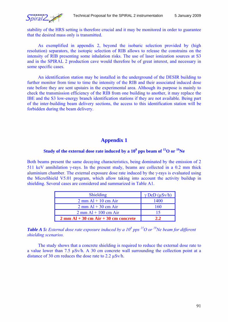
Technical Proposal for the SPIRAL 2 instrumentation 5 January 2009
91
stability of the HRS setting is therefore crucial and it may be monitored in order to guarantee that the desired mass only is transmitted.
As exemplified in appendix 2, beyond the isobaric selection provided by (high
resolution) separators, the isotopic selection of RIB allows to release the constrains on the intensity of RIB presenting some inhalation risks. The use of laser ionization sources at S3 and in the SPIRAL 2 production cave would therefore be of great interest, and necessary in some specific cases.
An identification station may be installed in the underground of the DESIR building to
further monitor from time to time the intensity of the RIB and their associated induced dose rate before they are sent upstairs in the experimental area. Although its purpose is mainly to check the transmission efficiency of the RIB from one building to another, it may replace the IBE and the S3 low-energy branch identification stations if they are not available. Being part of the inter-building beam delivery sections, the access to this identification station will be forbidden during the beam delivery.
Appendix 1
Study of the external dose rate induced by a 108 pps beam of 15O or 19Ne Both beams present the same decaying characteristics, being dominated by the emission of 2 511 keV annihilation γ-rays. In the present study, beams are collected in a 0.2 mm thick aluminium chamber. The external exposure dose rate induced by the γ-rays is evaluated using the MicroShield V5.01 program, which allow taking into account the activity buildup in shielding. Several cases are considered and summarized in Table A1.
Shielding γ DeD (µSv/h)
2 mm Al + 10 cm Air 1400 2 mm Al + 30 cm Air 160 2 mm Al + 100 cm Air 15
2 mm Al + 30 cm Air + 30 cm concrete 2.2 Table A 5: External dose rate exposure induced by a 108 pps 15O or 19Ne beam for different shielding scenarios.
The study shows that a concrete shielding is required to reduce the external dose rate to a value lower than 7.5 µSv/h. A 30 cm concrete wall surrounding the collection point at a distance of 30 cm reduces the dose rate to 2.2 µSv/h.
Technical Proposal for the SPIRAL 2 instrumentation 5 January 2009
92
Appendix 2
Inhalation risks associated with a 1 week run with 132-137Sn beams produced at SPIRAL2 by means of neutron-induced fission of 238U
The aim of the study is to evaluate the intensity limitations that may be required in order to ensure that an accidental released of the activity collected in the DESIR building will not exceed 1 LPCA in the surroundings. Two scenarios are considered: - the delivery of pure Sn isotopic beams produced by means of laser ionization and isobaric
mass separation - the delivery of cocktail beams of isobaric ions (from Ba to Cd)
In both cases, the presumably available intensities are taken from the evaluated target inventory at equilibrium, considering 1014 fissions per second in a 11 g/cm3 UCx target (https://edms.in2p3.fr/file/I-011067/2/Prod_cible_endf_v2.xls). Although not realistic, identical ionization, release, transport and separation efficiencies are assumed, independent on the considered elements. 1. Evaluation of intensity limitations induced by the 1 LPCA limit The LPCA varies from one isotope to another. It corresponds for a given isotope to a maximum activity per unit of volume (Bq/m3) compatible with the dose affordable by inhalation. In the present study, we consider that people working in the DESIR building must not incorporate by inhalation a dose larger than 20 mSv. Taking 131I as an example, this inhalation dose limit translates into a LPCA limit of about 420 Bq/m3. We assume arbitrarily in the present study that all the collected activity is released instantaneously and that it will be homogeneously spread in a volume of 500 m3 (10 * 10 * 5 m3). The LPCA limit for 131I then translates into a maximum activity of 420 * 500 = 2.1 105 Bq. The lifetime of 131I being 8 days, such an activity will be reached inside the collection chamber already after 1 day for a beam intensity of 2.4 106 pps, and after 3 days for a beam intensity of 8.8 105 pps.
In order to determine the beam intensity limitation to be applied, one needs first to
determine as a function of the beam intensity and the collection time the collected activity that may be accidentally released. Taking into account the composition of the collected beam, the lifetime of the isotopes and of their decay products, one can estimate the amount of LPCA associated with the mixture as a function of time and beam intensity. Depending on the scheduled running time, the beam intensity reduction to be applied corresponds to a limit of 1 LPCA. In the present study, the DARWIN code was used, which allows evaluating the induced LPCA after a given collection time as well as during the decrease of the activity implanted. 2. Delivery of pure mass separated Sn beams
In this particular study, it is assumed that the laser ionization allows the extraction of pure Sn beams, although Cs ions will be also produced by surface ionization in the hot cavity. The production of Cs inside the target is already 1 order of magnitude higher for A=133, and is 5 order of magnitude higher for A=137. The study therefore assumes that technical solutions to
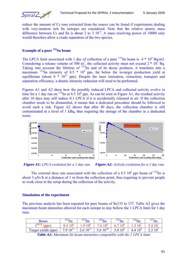
Technical Proposal for the SPIRAL 2 instrumentation 5 January 2009
93
reduce the amount of Cs ions extracted from the source can be found if experiments dealing with very-neutron rich Sn isotopes are considered. Note that the relative atomic mass difference between Cs and Sn is about 2 to 3 10-4. A mass resolving power of 10000 only would therefore allow a crude separation of the two species. Example of a pure 132Sn beam The LPCA limit associated with 1 day of collection of a pure 132Sn beam is 4 * 104 Bq/m3. Considering a release volume of 500 m3, the collected activity must not exceed 2 * 107 Bq. Taking into account the lifetime of 132Sn and of its decay products, it translates into a maximum 132Sn intensity of 8.5 * 106 pps, far below the in-target production yield at equilibrium (about 8 * 1011 pps). Despite the laser ionization, extraction, transport and separation efficiency, a drastic intensity reduction will need to be performed. Figures A1 and A2 show how the possibly induced LPCA and collected activity evolve in time for a 1 day run on 132Sn at 8.5 106 pps. As can be seen in Figure A1, the residual activity after 10 days may still induce 0.1 LPCA if it is accidentally released in air. If the collection chamber needs to be dismantled, it means that a dedicated procedure should be followed to avoid such a risk. Figure A2 shows that after 40 days, the collection chamber is still contaminated at a level of 1 kBq, thus requiring the storage of the chamber in a dedicated room.
Activity evolution
1.E+02
1.E+03
1.E+04
1.E+05
1.E+06
1.E+07
1.E+08
0 10 20 30 40
Collection and cooling time (day)
Act
ivity
(Bq)
Coll. 1j
LPCA evolution
1.E-03
1.E-02
1.E-01
1.E+00
0 5 10 15 20 25 30Collection and cooling time (day)
LPC
A
Coll. 1j
Figure A1: LPCA evolution for a 1 day run. Figure A2: Activity evolution for a 1 day run.
The external dose rate associated with the collection of a 8.5 106 pps beam of 132Sn is about 3 µSv/h at a distance of 1 m from the collection point, thus requiring to prevent people to work close to the setup during the collection of the activity. Simulation of the experiment The previous analysis has been repeated for pure beams of Sn133 to 137. Table A2 gives the maximum beam intensities allowed for each isotope to stay bellow the 1 LPCA limit for 1 day runs.
Beam 132Sn 133Sn 134Sn 135Sn 136Sn 137Sn
IMAX (pps) 8.5 106 1.9 106 7.6 106 6.7 106 1.3 107 5.2 107 Target yields (pps) 7.9 1011 2.6 1011 5.6 1010 5.8 109 4.4 108 2.2 107
Table A2: Maximum Sn beam intensities compatible with the 1 LPCA limit
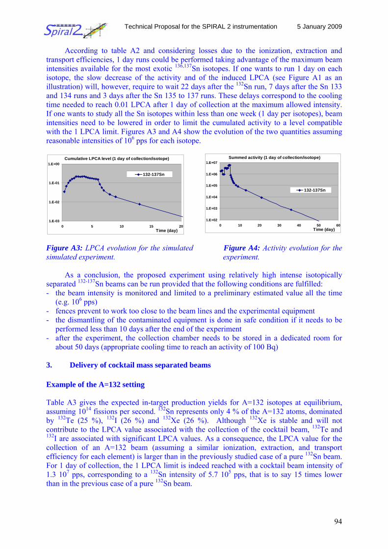
Technical Proposal for the SPIRAL 2 instrumentation 5 January 2009
94
According to table A2 and considering losses due to the ionization, extraction and transport efficiencies, 1 day runs could be performed taking advantage of the maximum beam intensities available for the most exotic 136,137Sn isotopes. If one wants to run 1 day on each isotope, the slow decrease of the activity and of the induced LPCA (see Figure A1 as an illustration) will, however, require to wait 22 days after the 132Sn run, 7 days after the Sn 133 and 134 runs and 3 days after the Sn 135 to 137 runs. These delays correspond to the cooling time needed to reach 0.01 LPCA after 1 day of collection at the maximum allowed intensity. If one wants to study all the Sn isotopes within less than one week (1 day per isotopes), beam intensities need to be lowered in order to limit the cumulated activity to a level compatible with the 1 LPCA limit. Figures A3 and A4 show the evolution of the two quantities assuming reasonable intensities of 106 pps for each isotope.
Figure A3: LPCA evolution for the simulated Figure A4: Activity evolution for the simulated experiment. experiment.
As a conclusion, the proposed experiment using relatively high intense isotopically separated 132-137Sn beams can be run provided that the following conditions are fulfilled: - the beam intensity is monitored and limited to a preliminary estimated value all the time
(e.g. 106 pps) - fences prevent to work too close to the beam lines and the experimental equipment - the dismantling of the contaminated equipment is done in safe condition if it needs to be
performed less than 10 days after the end of the experiment - after the experiment, the collection chamber needs to be stored in a dedicated room for
about 50 days (appropriate cooling time to reach an activity of 100 Bq) 3. Delivery of cocktail mass separated beams Example of the A=132 setting Table A3 gives the expected in-target production yields for A=132 isotopes at equilibrium, assuming 1014 fissions per second. 132Sn represents only 4 % of the A=132 atoms, dominated by 132Te (25 %), 132I (26 %) and 132Xe (26 %). Although 132Xe is stable and will not contribute to the LPCA value associated with the collection of the cocktail beam, 132Te and 132I are associated with significant LPCA values. As a consequence, the LPCA value for the collection of an A=132 beam (assuming a similar ionization, extraction, and transport efficiency for each element) is larger than in the previously studied case of a pure 132Sn beam. For 1 day of collection, the 1 LPCA limit is indeed reached with a cocktail beam intensity of 1.3 107 pps, corresponding to a 132Sn intensity of 5.7 105 pps, that is to say 15 times lower than in the previous case of a pure 132Sn beam.
Cumulative LPCA level (1 day of collection/isotope)
1.E-03
1.E-02
1.E-01
1.E+00
0 5 10 15 20Time (day)
132-137Sn
Summed activity (1 day of collection/isotope)
1.E+02
1.E+03
1.E+04
1.E+05
1.E+06
1.E+07
0 10 20 30 40 50 60Time (day)
132-137Sn
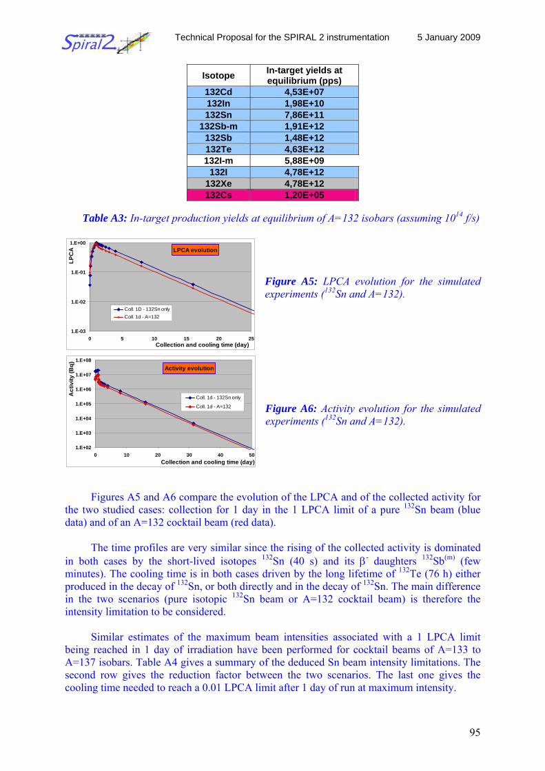
Technical Proposal for the SPIRAL 2 instrumentation 5 January 2009
95
Isotope In-target yields at equilibrium (pps)
132Cd 4,53E+07 132In 1,98E+10 132Sn 7,86E+11
132Sb-m 1,91E+12 132Sb 1,48E+12 132Te 4,63E+12 132I-m 5,88E+09
132I 4,78E+12 132Xe 4,78E+12 132Cs 1,20E+05
Table A3: In-target production yields at equilibrium of A=132 isobars (assuming 1014 f/s)
Figure A5: LPCA evolution for the simulated experiments (132Sn and A=132). Figure A6: Activity evolution for the simulated experiments (132Sn and A=132).
Figures A5 and A6 compare the evolution of the LPCA and of the collected activity for
the two studied cases: collection for 1 day in the 1 LPCA limit of a pure 132Sn beam (blue data) and of an A=132 cocktail beam (red data).
The time profiles are very similar since the rising of the collected activity is dominated
in both cases by the short-lived isotopes 132Sn (40 s) and its β- daughters 132Sb(m) (few minutes). The cooling time is in both cases driven by the long lifetime of 132Te (76 h) either produced in the decay of 132Sn, or both directly and in the decay of 132Sn. The main difference in the two scenarios (pure isotopic 132Sn beam or A=132 cocktail beam) is therefore the intensity limitation to be considered.
Similar estimates of the maximum beam intensities associated with a 1 LPCA limit
being reached in 1 day of irradiation have been performed for cocktail beams of A=133 to A=137 isobars. Table A4 gives a summary of the deduced Sn beam intensity limitations. The second row gives the reduction factor between the two scenarios. The last one gives the cooling time needed to reach a 0.01 LPCA limit after 1 day of run at maximum intensity.
LPCA evolution
1.E-03
1.E-02
1.E-01
1.E+00
0 5 10 15 20 25Collection and cooling time (day)
LPC
A
Coll. 1D - 132Sn onlyColl. 1d - A=132
Activity evolution
1.E+02
1.E+03
1.E+04
1.E+05
1.E+06
1.E+07
1.E+08
0 10 20 30 40 50Collection and cooling time (day)
Act
ivity
(Bq)
Coll. 1d - 132Sn only
Coll. 1d - A=132
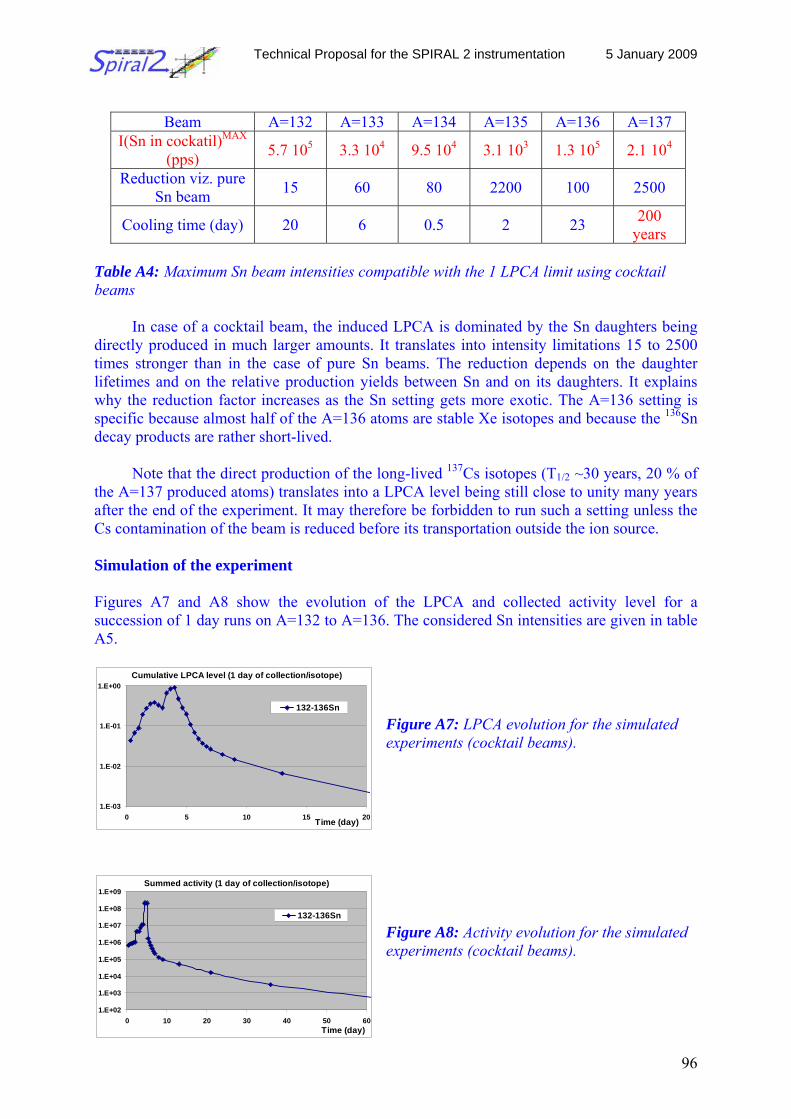
Technical Proposal for the SPIRAL 2 instrumentation 5 January 2009
96
Beam A=132 A=133 A=134 A=135 A=136 A=137
I(Sn in cockatil)MAX (pps) 5.7 105 3.3 104 9.5 104 3.1 103 1.3 105 2.1 104
Reduction viz. pure Sn beam 15 60 80 2200 100 2500
Cooling time (day) 20 6 0.5 2 23 200 years
Table A4: Maximum Sn beam intensities compatible with the 1 LPCA limit using cocktail beams
In case of a cocktail beam, the induced LPCA is dominated by the Sn daughters being directly produced in much larger amounts. It translates into intensity limitations 15 to 2500 times stronger than in the case of pure Sn beams. The reduction depends on the daughter lifetimes and on the relative production yields between Sn and on its daughters. It explains why the reduction factor increases as the Sn setting gets more exotic. The A=136 setting is specific because almost half of the A=136 atoms are stable Xe isotopes and because the 136Sn decay products are rather short-lived.
Note that the direct production of the long-lived 137Cs isotopes (T1/2 ~30 years, 20 % of
the A=137 produced atoms) translates into a LPCA level being still close to unity many years after the end of the experiment. It may therefore be forbidden to run such a setting unless the Cs contamination of the beam is reduced before its transportation outside the ion source. Simulation of the experiment Figures A7 and A8 show the evolution of the LPCA and collected activity level for a succession of 1 day runs on A=132 to A=136. The considered Sn intensities are given in table A5.
Figure A7: LPCA evolution for the simulated experiments (cocktail beams).
Figure A8: Activity evolution for the simulated experiments (cocktail beams).
Cumulative LPCA level (1 day of collection/isotope)
1.E-03
1.E-02
1.E-01
1.E+00
0 5 10 15 20Time (day)
132-136Sn
Summed activity (1 day of collection/isotope)
1.E+02
1.E+03
1.E+04
1.E+05
1.E+06
1.E+07
1.E+08
1.E+09
0 10 20 30 40 50 60Time (day)
132-136Sn
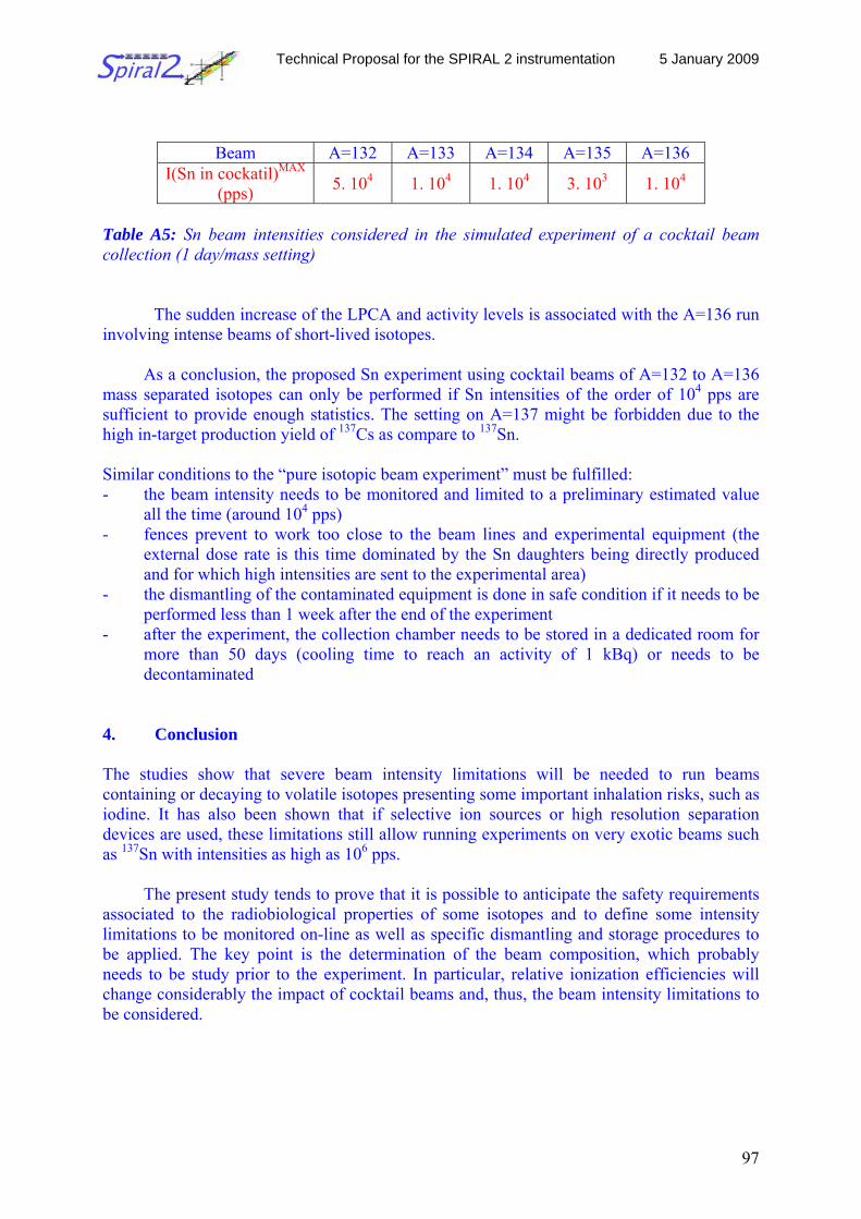
Technical Proposal for the SPIRAL 2 instrumentation 5 January 2009
97
Beam A=132 A=133 A=134 A=135 A=136 I(Sn in cockatil)MAX
(pps) 5. 104 1. 104 1. 104 3. 103 1. 104
Table A5: Sn beam intensities considered in the simulated experiment of a cocktail beam collection (1 day/mass setting)
The sudden increase of the LPCA and activity levels is associated with the A=136 run
involving intense beams of short-lived isotopes.
As a conclusion, the proposed Sn experiment using cocktail beams of A=132 to A=136 mass separated isotopes can only be performed if Sn intensities of the order of 104 pps are sufficient to provide enough statistics. The setting on A=137 might be forbidden due to the high in-target production yield of 137Cs as compare to 137Sn.
Similar conditions to the “pure isotopic beam experiment” must be fulfilled: - the beam intensity needs to be monitored and limited to a preliminary estimated value
all the time (around 104 pps) - fences prevent to work too close to the beam lines and experimental equipment (the
external dose rate is this time dominated by the Sn daughters being directly produced and for which high intensities are sent to the experimental area)
- the dismantling of the contaminated equipment is done in safe condition if it needs to be performed less than 1 week after the end of the experiment
- after the experiment, the collection chamber needs to be stored in a dedicated room for more than 50 days (cooling time to reach an activity of 1 kBq) or needs to be decontaminated
4. Conclusion The studies show that severe beam intensity limitations will be needed to run beams containing or decaying to volatile isotopes presenting some important inhalation risks, such as iodine. It has also been shown that if selective ion sources or high resolution separation devices are used, these limitations still allow running experiments on very exotic beams such as 137Sn with intensities as high as 106 pps.
The present study tends to prove that it is possible to anticipate the safety requirements
associated to the radiobiological properties of some isotopes and to define some intensity limitations to be monitored on-line as well as specific dismantling and storage procedures to be applied. The key point is the determination of the beam composition, which probably needs to be study prior to the experiment. In particular, relative ionization efficiencies will change considerably the impact of cocktail beams and, thus, the beam intensity limitations to be considered.
Technical Proposal for the SPIRAL 2 instrumentation 5 January 2009
98
5 Organization and Responsibilities 5.1 Management Board
• Representatives: - Spokesperson: B. Blank (CENBG) - GANIL liaison: J.C. Thomas (GANIL) -
• Technical working groups conveners: - RFQ: G. Ban (LPC) - HRS: B. Blank (CENBG) - Beam monitoring station: Ph. Dessagne (IPHC) - Beam preparation and off-line sources: D. Lunney (CSNSM) P. Delahaye (GANIL) - DESIR building: F. Delalee (CENBG) - DESIR safety: J.-C. Thomas (GANIL)
• Physics and Instrumentation coordinators - LUMIERE: F. Le Blanc (IPNO), G. Neyens (Leuven), P. Campbell (Manchester) - BESTIOL: M.J.G. Borge (Madrid) - MLLTRAP: P. Thirolf (Munich) - MOtrap: H. Wilschut (KVI) - LPCTrap: O. Naviliat-Cuncic, E. Liénard (LPC Caen)
5.2 WBS - work package break down structure In the work package definitions, we give only general tasks which are related to DESIR in a global sense. The design and installation of experimental equipment is the duty of the collaborations which will run these installations.
Task Number
Task name Description of Task Coordinators
1 RFQ SHIRAC Development and construction of a high-intensity cooler and buncher
G. Ban
2 HRS Design and construction of a high-resolution separator
B. Blank
3 DESIR hall Design and layout of the DESIR building
F. Delalee
4 GPIB Design and construction of a general purpose ion buncher
D. Lunney, P. Delahaye
5 Stable ion sources Installation of two stable ion sources
F. Le Blanc
6 Beam monitoring station
Tape and detector system to identify and characterize
radioactive ion beam before sending to experimental setups
P. Dessagne
7 Security and radioprotection
Developments and rules to ensure radioprotection and security at
DESIR
J.-C. Thomas
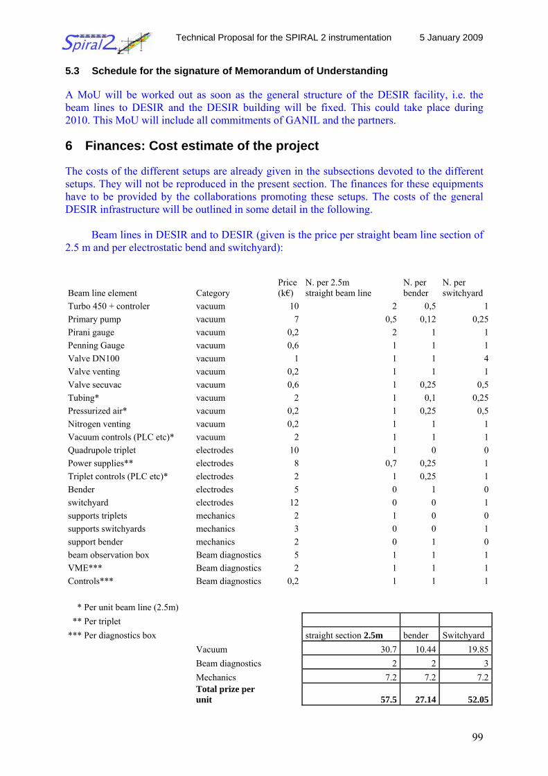
Technical Proposal for the SPIRAL 2 instrumentation 5 January 2009
99
5.3 Schedule for the signature of Memorandum of Understanding
A MoU will be worked out as soon as the general structure of the DESIR facility, i.e. the beam lines to DESIR and the DESIR building will be fixed. This could take place during 2010. This MoU will include all commitments of GANIL and the partners.
6 Finances: Cost estimate of the project The costs of the different setups are already given in the subsections devoted to the different setups. They will not be reproduced in the present section. The finances for these equipments have to be provided by the collaborations promoting these setups. The costs of the general DESIR infrastructure will be outlined in some detail in the following.
Beam lines in DESIR and to DESIR (given is the price per straight beam line section of 2.5 m and per electrostatic bend and switchyard):
Beam line element Category Price (k€)
N. per 2.5m straight beam line
N. per bender
N. per switchyard
Turbo 450 + controler vacuum 10 2 0,5 1Primary pump vacuum 7 0,5 0,12 0,25Pirani gauge vacuum 0,2 2 1 1Penning Gauge vacuum 0,6 1 1 1Valve DN100 vacuum 1 1 1 4Valve venting vacuum 0,2 1 1 1Valve secuvac vacuum 0,6 1 0,25 0,5Tubing* vacuum 2 1 0,1 0,25Pressurized air* vacuum 0,2 1 0,25 0,5Nitrogen venting vacuum 0,2 1 1 1Vacuum controls (PLC etc)* vacuum 2 1 1 1Quadrupole triplet electrodes 10 1 0 0Power supplies** electrodes 8 0,7 0,25 1Triplet controls (PLC etc)* electrodes 2 1 0,25 1Bender electrodes 5 0 1 0switchyard electrodes 12 0 0 1supports triplets mechanics 2 1 0 0supports switchyards mechanics 3 0 0 1support bender mechanics 2 0 1 0beam observation box Beam diagnostics 5 1 1 1VME*** Beam diagnostics 2 1 1 1Controls*** Beam diagnostics 0,2 1 1 1 * Per unit beam line (2.5m) ** Per triplet *** Per diagnostics box straight section 2.5m bender Switchyard Vacuum 30.7 10.44 19.85 Beam diagnostics 2 2 3 Mechanics 7.2 7.2 7.2
Total prize per unit 57.5 27.14 52.05
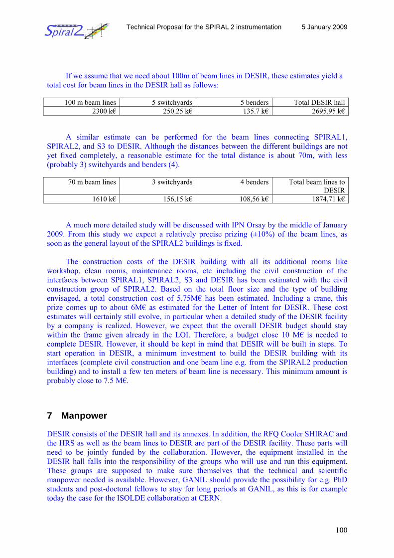
Technical Proposal for the SPIRAL 2 instrumentation 5 January 2009
100
If we assume that we need about 100m of beam lines in DESIR, these estimates yield a total cost for beam lines in the DESIR hall as follows:
100 m beam lines 5 switchyards 5 benders Total DESIR hall2300 k€ 250.25 k€ 135.7 k€ 2695.95 k€
A similar estimate can be performed for the beam lines connecting SPIRAL1, SPIRAL2, and S3 to DESIR. Although the distances between the different buildings are not yet fixed completely, a reasonable estimate for the total distance is about 70m, with less (probably 3) switchyards and benders (4).
70 m beam lines 3 switchyards 4 benders Total beam lines to DESIR
1610 k€ 156,15 k€ 108,56 k€ 1874,71 k€
A much more detailed study will be discussed with IPN Orsay by the middle of January 2009. From this study we expect a relatively precise prizing (±10%) of the beam lines, as soon as the general layout of the SPIRAL2 buildings is fixed.
The construction costs of the DESIR building with all its additional rooms like
workshop, clean rooms, maintenance rooms, etc including the civil construction of the interfaces between SPIRAL1, SPIRAL2, S3 and DESIR has been estimated with the civil construction group of SPIRAL2. Based on the total floor size and the type of building envisaged, a total construction cost of 5.75M€ has been estimated. Including a crane, this prize comes up to about 6M€ as estimated for the Letter of Intent for DESIR. These cost estimates will certainly still evolve, in particular when a detailed study of the DESIR facility by a company is realized. However, we expect that the overall DESIR budget should stay within the frame given already in the LOI. Therefore, a budget close 10 M€ is needed to complete DESIR. However, it should be kept in mind that DESIR will be built in steps. To start operation in DESIR, a minimum investment to build the DESIR building with its interfaces (complete civil construction and one beam line e.g. from the SPIRAL2 production building) and to install a few ten meters of beam line is necessary. This minimum amount is probably close to 7.5 M€. 7 Manpower DESIR consists of the DESIR hall and its annexes. In addition, the RFQ Cooler SHIRAC and the HRS as well as the beam lines to DESIR are part of the DESIR facility. These parts will need to be jointly funded by the collaboration. However, the equipment installed in the DESIR hall falls into the responsibility of the groups who will use and run this equipment. These groups are supposed to make sure themselves that the technical and scientific manpower needed is available. However, GANIL should provide the possibility for e.g. PhD students and post-doctoral fellows to stay for long periods at GANIL, as this is for example today the case for the ISOLDE collaboration at CERN.
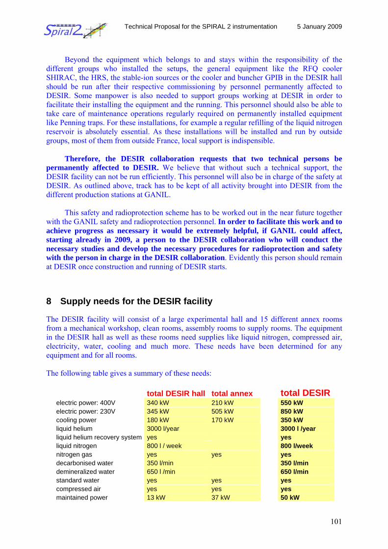
Technical Proposal for the SPIRAL 2 instrumentation 5 January 2009
101
Beyond the equipment which belongs to and stays within the responsibility of the
different groups who installed the setups, the general equipment like the RFQ cooler SHIRAC, the HRS, the stable-ion sources or the cooler and buncher GPIB in the DESIR hall should be run after their respective commissioning by personnel permanently affected to DESIR. Some manpower is also needed to support groups working at DESIR in order to facilitate their installing the equipment and the running. This personnel should also be able to take care of maintenance operations regularly required on permanently installed equipment like Penning traps. For these installations, for example a regular refilling of the liquid nitrogen reservoir is absolutely essential. As these installations will be installed and run by outside groups, most of them from outside France, local support is indispensible.
Therefore, the DESIR collaboration requests that two technical persons be
permanently affected to DESIR. We believe that without such a technical support, the DESIR facility can not be run efficiently. This personnel will also be in charge of the safety at DESIR. As outlined above, track has to be kept of all activity brought into DESIR from the different production stations at GANIL.
This safety and radioprotection scheme has to be worked out in the near future together with the GANIL safety and radioprotection personnel. In order to facilitate this work and to achieve progress as necessary it would be extremely helpful, if GANIL could affect, starting already in 2009, a person to the DESIR collaboration who will conduct the necessary studies and develop the necessary procedures for radioprotection and safety with the person in charge in the DESIR collaboration. Evidently this person should remain at DESIR once construction and running of DESIR starts.
8 Supply needs for the DESIR facility The DESIR facility will consist of a large experimental hall and 15 different annex rooms from a mechanical workshop, clean rooms, assembly rooms to supply rooms. The equipment in the DESIR hall as well as these rooms need supplies like liquid nitrogen, compressed air, electricity, water, cooling and much more. These needs have been determined for any equipment and for all rooms. The following table gives a summary of these needs:
total DESIR hall total annex total DESIRelectric power: 400V 340 kW 210 kW 550 kW electric power: 230V 345 kW 505 kW 850 kW cooling power 180 kW 170 kW 350 kW liquid helium 3000 l/year 3000 l /year liquid helium recovery system yes yes liquid nitrogen 800 l / week 800 l/week nitrogen gas yes yes yes decarbonised water 350 l/min 350 l/min demineralized water 650 l /min 650 l/min standard water yes yes yes compressed air yes yes yes maintained power 13 kW 37 kW 50 kW
Technical Proposal for the SPIRAL 2 instrumentation 5 January 2009
102
9 Relations with other projects As other radioactive beam facilities of its type like ISOLDE or the low-energy part of FAIR, DESIR will use equipment developed and designed for its particular use at an ISOL facility. Therefore synergies exist with FAIR and others as summarized in the following list:
• Beam preparation: RFQs, traps, low-energy beam diagnostics • Trap-assisted spectroscopy (MATS) • Laser spectroscopy (LASPEC) • Neutron detection (NCAP) • New types of charged-particle and gamma detectors (e.g. LaBr2)
A certain number of setups which will be used at DESIR are meant to travel. This is the
case of the TAS setup, the TETRA setup, part of the LUMIERE facility, and other “lighter” equipment. Therefore, the experimental program at DESIR has to be coordinated at least to some extent with other major facilities like NUSTAR at FAIR or ISOLDE.