Embed Size (px)
Citation preview
Two-, three-, or four-wire proximity sensors contain a transistor oscillator and a snap-action ampli�er. This provides exceedingly highaccuracy to a set switching point, even with very slowly approaching targets. Switching characteristics are una�ected by supplyvoltage �uctuations within the speci�ed limits.
The sensors can drive electromechanical relays, counters, solenoids, or electronic modules, and interface directly with logic systemsor programmable controllers without additional interface circuitry. They are available with either NPN output transistors (currentsinking) or PNP output transistors (current sourcing).
Load current ratings vary from 100 mA to 200 mA depending on physical size. Standard voltage range is 10-30 VDC with certaintypes available for 10-65 VDC. All models incorporate wire-break, transient and reverse polarity protection.Power-On false pulse suppression is also standard.
TURCK DC sensors with a Voltage Range designation of "4", "6" or "8" in the part number are short-circuit and overload protected(automatic reset). These sensors incorporate a specially designed circuit which continuously monitors the ON state output currentfor a short-circuit or overload condition. If either of these fault conditions occurs, the output is turned OFF and pulse tested until thefault is removed. This added protection causes a ≤1.8 V drop across the output in the normal ON state. This may be a problem wheninterfacing with some logic low inputs (see TTL compatibility).
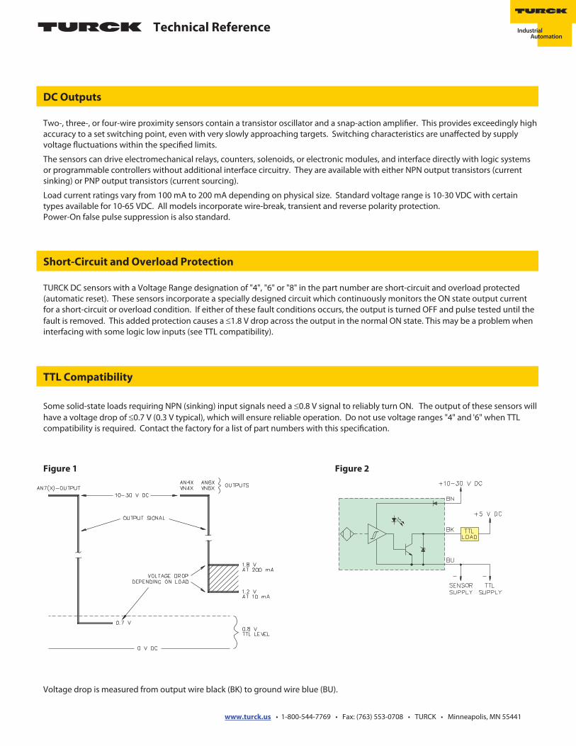
Some solid-state loads requiring NPN (sinking) input signals need a ≤0.8 V signal to reliably turn ON. The output of these sensors willhave a voltage drop of ≤0.7 V (0.3 V typical), which will ensure reliable operation. Do not use voltage ranges "4" and '6" when TTLcompatibility is required. Contact the factory for a list of part numbers with this speci�cation.
TTL Compatibility
DC Outputs
Short-Circuit and Overload Protection
Voltage drop is measured from output wire black (BK) to ground wire blue (BU).
Figure 2Figure 1
Technical Reference
www.turck.us • 1-800-544-7769 • Fax: (763) 553-0708 • TURCK • Minneapolis, MN 55441
DC Outputs
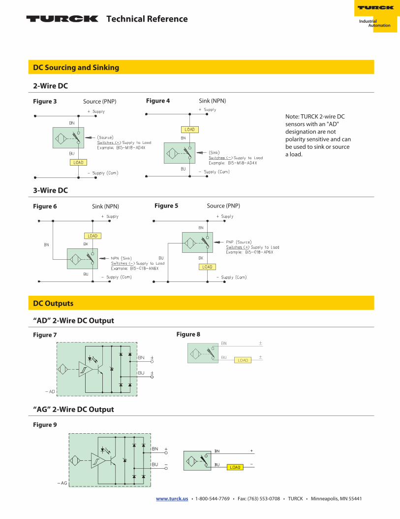
DC Sourcing and Sinking
Figure 6 Sink (NPN)
“AG” 2-Wire DC Output
Note: TURCK 2-wire DCsensors with an "AD"designation are notpolarity sensitive and canbe used to sink or sourcea load.
2-Wire DC
Figure 4 Sink (NPN)Figure 3 Source (PNP)
3-Wire DC
Figure 5 Source (PNP)
Figure 9
“AD” 2-Wire DC Output
Figure 7 Figure 8
Technical Reference
www.turck.us • 1-800-544-7769 • Fax: (763) 553-0708 • TURCK • Minneapolis, MN 55441
DC Outputs
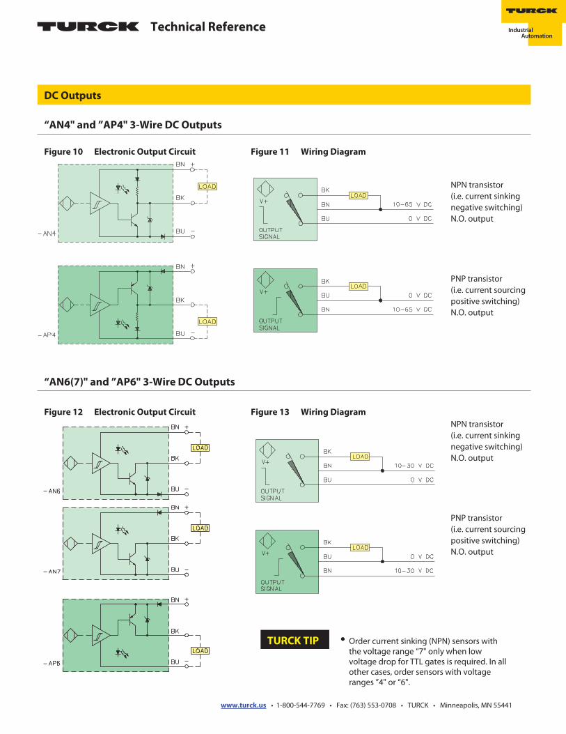
“AN6(7)" and ”AP6" 3-Wire DC Outputs
Figure 13 Wiring DiagramFigure 12 Electronic Output Circuit
Figure 11 Wiring DiagramFigure 10 Electronic Output Circuit
“AN4" and ”AP4" 3-Wire DC Outputs
NPN transistor(i.e. current sinkingnegative switching)N.O. output
PNP transistor(i.e. current sourcingpositive switching)N.O. output
NPN transistor(i.e. current sinkingnegative switching)N.O. output
PNP transistor(i.e. current sourcingpositive switching)N.O. output
• Order current sinking (NPN) sensors withthe voltage range “7" only when lowvoltage drop for TTL gates is required. In allother cases, order sensors with voltageranges ”4" or “6".
TURCK TIP
Technical Reference
www.turck.us • 1-800-544-7769 • Fax: (763) 553-0708 • TURCK • Minneapolis, MN 55441
DC Outputs
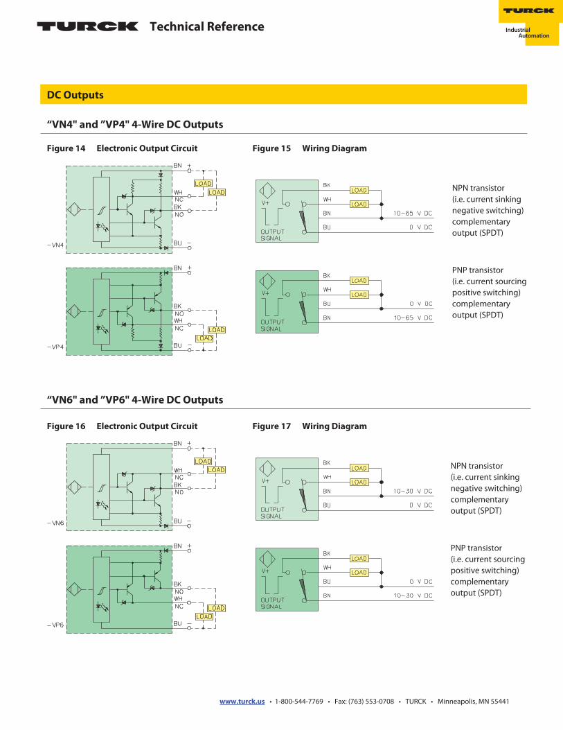
“VN6" and ”VP6" 4-Wire DC Outputs
Figure 17 Wiring DiagramFigure 16 Electronic Output Circuit
NPN transistor(i.e. current sinkingnegative switching)complementaryoutput (SPDT)
PNP transistor(i.e. current sourcingpositive switching)complementaryoutput (SPDT)
“VN4" and ”VP4" 4-Wire DC Outputs
NPN transistor(i.e. current sinkingnegative switching)complementaryoutput (SPDT)
PNP transistor(i.e. current sourcingpositive switching)complementaryoutput (SPDT)
Figure 15 Wiring DiagramFigure 14 Electronic Output Circuit
Technical Reference
www.turck.us • 1-800-544-7769 • Fax: (763) 553-0708 • TURCK • Minneapolis, MN 55441
Series/Parallel Connection
DC Outputs
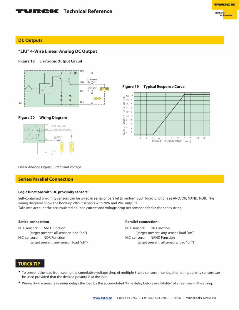
Figure 20 Wiring Diagram
“LIU" 4-Wire Linear Analog DC Output
Figure 19 Typical Response Curve
Figure 18 Electronic Output Circuit
Linear Analog Output; Current and Voltage
Logic functions with DC proximity sensors:
Self-contained proximity sensors can be wired in series or parallel to perform such logic functions as AND, OR, NAND, NOR. Thewiring diagrams show the hook-up o�our sensors with NPN and PNP outputs.Take into account the accumulated no-load current and voltage drop per sensor added in the series string.
Parallel-connection:
N.O. sensors: OR Function(target present, any sensor: load “on”)
N.C. sensors: NAND Function(target present, all sensors: load “o�”)
• To prevent the load from seeing the cumulative voltage drop of multiple 3-wire sensors in series, alternating polarity sensors canbe used provided that the desired polarity is at the load.
• Wiring 3-wire sensors in series delays the load by the accumulated “time delay before availability" of all sensors in the string.
Series-connection:
N.O. sensors: AND Function(target present, all sensors: load “on”)
N.C. sensors: NOR Function(target present, any sensor: load “o�”)
TURCK TIP
Technical Reference
www.turck.us • 1-800-544-7769 • Fax: (763) 553-0708 • TURCK • Minneapolis, MN 55441