Embed Size (px)
Citation preview

TechnicalReport 14-13
National Cooperativefor the Disposal of Radioactive Waste
Hardstrasse 73CH-5430 Wettingen
SwitzerlandTel. +41 56 437 11 11
www.nagra.ch
High-level wasterepository-induced effects
O.X. Leupin P. Smith, P. Marschall,,L. Johnson, D. Savage, V. Cloet,
J. Schneider and R. Senger
October 2016


National Cooperativefor the Disposal of Radioactive Waste
Hardstrasse 73CH-5430 Wettingen
SwitzerlandTel. +41 56 437 11 11
www.nagra.ch
TechnicalReport 14-13
O.X. Leupin P. Smith , P. Marschall , 1 2 1,L. Johnson , D. Savage , V. Cloet , 1 3 1
J. Schneider and R. Senger 1 4
1 2 3 4 Nagra, SAM, Savage earth, Intera Inc.
October 2016
High-level wasterepository-induced effects

"Copyright © 2016 by Nagra, Wettingen (Switzerland) / All rights reserved.
All parts of this work are protected by copyright. Any utilisation outwith the remit of the
copyright law is unlawful and liable to prosecution. This applies in particular to translations,
storage and processing in electronic systems and programs, microfilms, reproductions etc."
ISSN 1015-2636
This status report presents the result of work in progress and is intended to provide rapid
dissemination of current information. The methods used and results obtained will be
reassessed in the course of Stage 3 of the Sectoral Plan "Deep Geological Repositories".

I NAGRA NTB 14-13
Abstract This status report aims at describing and assessing the interactions of the radioactive waste emplaced in a high-level waste (HLW) repository with the engineered materials and the Opalinus Clay host rock. The Opalinus Clay has a thickness of about 100 m in the proposed siting regions. Among other things the results are used to steer the RD&D programme of Nagra. The repository-induced effects considered in this report are of the following broad types:
Thermal effects: i.e. effects on the host rock and engineered barriers arising principally from the heat generated by the waste
Rock-mechanical effects: i.e. effects arising from the mechanical disturbance to the rock caused by the excavation of the emplacement rooms and other underground structures
Hydraulic and gas-related effects: i.e. the effects of repository resaturation and of gas generation, e.g. due to the corrosion of metals within the repository, on the host rock and engineered barriers
Chemical effects: i.e. chemical interactions between the waste, the engineered materials and the host rock, with a focus on chemical effects of the waste and engineered materials on the host rock
The assessment of the repository-induced effects shows that detrimental chemical and mechani-cal impacts are largely confined to the rock immediately adjacent to the excavations, thermal impacts are controllable by limiting the heat load and gas effects are limited by ensuring acceptably low gas production rates and by the natural tendency of the gas to escape along the excavations and the excavation damaged zone (EDZ) rather than through the undisturbed rock. Specific measures that are part of the current reference design are discussed in relation to their significance with respect to repository-induced effects.
The SF/HLW emplacement rooms (emplacement drifts) are designed, constructed, operated and finally backfilled in such a way that formation of excavation damaged zones is limited. Speci-fically this is achieved by restricting the size of the excavations and the depth of the repository, using a low-deformation, controlled construction and excavation method and by the fact that the excavations will be backfilled relatively soon after construction with a swelling backfill material. At expected repository depths, the rooms will need to be supported to ensure stability and worker protection; this will prevent rock falls and further extension of the EDZ. Based on the modelling results, it can be concluded that the extent of the EDZ around the HLW emplace-ment rooms will not exceed a thickness of one room diameter and that the average hydraulic conductance of the EDZ around emplacement rooms, access tunnels and shafts will not exceed a value of 10-7 m3/s. Self-sealing of the EDZ and low hydraulic gradients along the tunnels will result in negligible radionuclide transport by the EDZ pathway.
The relevant chemical interactions are taken into account when designing and assessing the per-formance of a HLW repository. In the current reference design, tunnel support is provided by a concrete liner. It is expected that degradation of the liner and corrosion of the steel canister and other supporting structures will lead to some alteration of the bentonite buffer and Opalinus Clay. These detrimental effects are taken into account in dose calculations and have been found not to have a significant impact on the calculated dose rates.
For the reference gas generation rates, the gas transport capacity of the Opalinus Clay is suffi-ciently high to dispel gas without invoking pathway dilation as a gas transport mechanism and without causing damage to the rock. Even if potential transport pathways for gas along the exca-

NAGRA NTB 14-13 II
vations and EDZ are disregarded, overpressures that would lead to the onset of pathway dilation are reached only in cases combining conservative gas generation rates with a low-permeability host rock, and these overpressures are still insufficient to cause rock damage. It is noted that such calculations do not incorporate transport of gas along the EDZ, which has a lower gas entry pressure than undisturbed Opalinus Clay.
The effects of heat from the HLW on the engineered and geological barriers cannot be com-pletely eliminated, but can be kept low by ensuring a sufficient duration of interim storage, limiting canister loading and a suitable canister emplacement density.

III NAGRA NTB 14-13
Zusammenfassung Das Ziel dieses Statusberichts ist es, in einem geologischen Tiefenlager für hochaktive Abfälle (HAA-Lager) die wechselseitige Beeinflussung von eingelagertem Abfall und eingebauten bau-technischen Materialien spezifisch auf das in den vorgeschlagenen Standortgebieten etwa 100 m mächtige Wirtgestein Opalinuston zu untersuchen, um das F&E-Programm der Nagra gezielter ausrichten zu können. Die im vorliegenden Bericht untersuchten lagerbedingten Einflüsse sind dabei:
Thermische Effekte: D.h. Auswirkungen auf das Wirtgestein und die technischen Barrie-ren, die vor allem durch die vom Abfall bedingte Zerfallswärme verursacht werden
Felsmechanische Effekte: D.h. Auswirkungen, die von der mechanischen Beanspruchung des Gesteins durch den Vortrieb der Lagerstollen und weiterer Untertagbauten hervor-gerufen werden
Hydraulische und durch Gasbildung bedingte Effekte: D.h. Auswirkungen durch die Wiederaufsättigung des Tiefenlagers und Gasbildung beispielsweise aufgrund von Metall-korrosion im Tiefenlager auf Wirtgestein und technische Barrieren
Chemische Effekte: D.h. chemische Wechselwirkungen von Abfall, bautechnischen Materialien und Wirtgestein, jedoch mit Schwerpunkt auf chemische Auswirkungen von Abfall und bautechnischen Materialien auf das Wirtgestein
Das Erfassen der lagerbedingten Einflüsse zeigt, dass sich chemischen und mechanischen Beeinträchtigungen auf das Gestein in unmittelbarer Umgebung der Untertagbauten beschränken. Die thermischen Auswirkungen werden durch die Begrenzung der Wärmelast kontrollierbar und diejenigen der Gasakkumulation werden durch niedrige Gasproduktionsraten und durch die Gasfreisetzung entlang der Auflockerungszone (AUZ) und einem tieferen Gas-eintrittsdruck in der AUZ als im ungestörten Opalinuston eingeschränkt. Spezifische Mass-nahmen werden als Teil des Referenzkonzepts im Hinblick auf deren Wirksamkeit, die lager-bedingten Einflüsse zu begrenzen, diskutiert.
Die HAA-Lagerstollen wurden so ausgelegt, gebaut, betrieben und schliesslich verfüllt, dass die Bildung einer Auflockerungszone (AUZ)1 möglichst begrenzt wird. Dies wird erreicht, indem die Grösse der Ausbruchzonen und die Tiefenlage des Lagers begrenzt werden, eine gebirgs-schonende, kontrollierte Ausbruch- und Ausbaumethode angewendet wird und dadurch, dass die Lagerstollen relativ schnell nach ihrem Ausbruch wieder mit einem quellenden Tonmaterial verfüllt werden. Auf entsprechender Lagertiefe werden die Lagerstollen durch Stützmittel aus-gebaut, um deren Stabilität und die Arbeitssicherheit zu gewährleisten. Dadurch wird Nachfall und eine weitere Ausdehnung der AUZ verhindert. Basierend auf Modellrechnungen kann abschliessend festgehalten werden, dass sich die AUZ nicht über einen Tunnelquerschnitt hinaus ausdehnt und dass das mittlere hydraulische Leitvermögen der AUZ um Lagerstollen, Zugangstunnel und Schächte einen Wert von 10-7 m3/s nicht übersteigt. Die anschliessende Selbstabdichtung der AUZ und die niedrigen hydraulischen Gradienten entlang der Bau- und Betriebstunnel führen zu einem vernachlässigbaren Radionuklidtransport durch die AUZ.
Chemische Wechselwirkungen werden sowohl bei der Planung als auch bei der Bewertung der Sicherheit eines HAA-Lagers in Betracht gezogen. Im derzeitigen Referenzkonzept ist ein Tunnelausbau mit Beton vorgesehen. Die Degradation des Betons und die Korrosion von Stahl-
1 Englisch: Excavation damaged zone (EDZ).
NAGRA NTB 14-13 IV
behältern und anderen stahlhaltigen Stützelementen werden die Bentonitverfüllung zu einem gewissen Grad umwandeln. Diese Umwandlungen werden in die Dosisberechnungen mit ein-bezogen und zeigen keinen signifikanten Einfluss auf die resultierende Dosis.
Die Gastransportfähigkeit von Opalinuston ist ausreichend, um für den Referenzfall das Regime der dilatanzkontrollierten Gasausbreitung als Gastransportmechanismus zu vermeiden und somit die Schädigung des Wirtgesteins zu verhindern. Auch wenn die AUZ als möglicher Transportpfad für Gas entlang der Ausbruchzonen bei den Gastransportmodellierungen nicht berücksichtigt wird, werden Überdrücke, die zu einer dilatanzkontrollierten Gasausbreitung führen könnten, nur dann erreicht, wenn konservative Annahmen zur Gasproduktion mit einem für Gas gering durchlässigen Wirtgestein kombiniert würden. Allerdings würden solche Über-drücke zu keiner signifikaten Schädigung des Gesteins führen.
Die Auswirkungen des Wärmeeintrags auf die technischen und geologischen Barrieren können in einem HAA-Lager zwar nicht vollständig eliminiert, jedoch durch eine entsprechend lange Zwischenlagerung, eine Begrenzung der Behälterladung sowie eine geeignete Einlagerungs-dichte niedrig gehalten werden.
V NAGRA NTB 14-13
Résumé Le présent rapport reflète les connaissances actuelles et traitement des perturbations induites, dans un dépôt profond, par les déchets radioactifs de haute activité (DHA) sur les matériaux des barrières ouvragées et inversement, ainsi que plus spécifiquement sur l’Argile à Opalinus, qui atteint une épaisseur d’environ 100 mètres dans les domaines d’implantation envisagés, pour mieux pouvoir justifier le programme de R&D de la Nagra.
Les perturbations ont été réparties en quatre catégories:
Effets thermiques: à savoir les effets sur la roche d’accueil et les barrières ouvragées dus principalement à la chaleur dégagée par les déchets
Effets géomécaniques: à savoir les effets résultant de la perturbation mécanique de la roche causée par l’excavation des galeries de stockage et d’autres structures souterraines
Effets hydrauliques et effets liés aux gaz : à savoir les effets, sur la roche d’accueil ou les barrières ouvragées, qui sont liés à la resaturation du dépôt profond et à la production de gaz générés, par exemple, par la corrosion de métaux dans le dépôt
Effets chimiques: à savoir les interactions de nature chimique entre les déchets, les barrières ouvragées et la roche d’accueil, l’accent étant mis en l’occurrence sur les effets des déchets et des matériaux des barrières techniques sur la roche d’accueil
L’examen des perturbations induites par le dépôt montrent que les impacts, tant chimiques que mécaniques, se limitent essentiellement à la zone proche de l’excavation. Les effets thermiques peuvent être contrôlés en restreignant la charge thermique. Les effets des gaz, quant à eux, peuvent être maîtrisés en veillant à des taux de production d’un niveau acceptable et du fait de la tendance naturelle du gaz à s’échapper le long des galeries excavées. Par ailleurs, la pression d’entrée du gaz est plus faible dans la zone perturbée par l’excavation que dans l’Argile à Opalinus non perturbée. Des mesures spécifiques visant à limiter les perturbations induites par le dépôt sont envisagées dans le cadre du concept de référence et évaluées quant à leur effi-cacité.
Dès la conception du dépôt, puis au cours des phases de construction, d’exploitation et de comblement, on va faire en sorte de limiter au maximum la formation d’une zone perturbée autour des galeries du dépôt DHA. On va ainsi limiter la taille de la zone excavée et la profon-deur du dépôt, procéder à l’excavation de manière contrôlée et en ménageant la roche et enfin combler les galeries relativement peu de temps après leur construction à l’aide de matériaux argileux gonflant. A la profondeur envisagée pour les dépôts géologiques, il faudra prévoir des soutènements afin de garantir la stabilité des galeries et la sécurité du personnel. Cette mesure évitera que des roches se détachent après l’excavation, entrainant un élargissement de la zone perturbée. Il est permis d’affirmer, en se fondant sur les modélisations, que la dimension de la zone perturbée ne sera pas supérieure à la section d’une galerie et que la conductivité hydraulique moyenne de la zone perturbée située autour des galeries et des tunnels et puits d’accès ne dépassera pas 10-7 m3/s. Au vu des propriétés auto-cicatrisantes de la zone perturbée et des faibles gradients hydrauliques qui règnent le long des tunnels de construction et d’exploitation, le transport de radionucléides dans la zone perturbée sera négligeable.
Les interactions chimiques sont prises en compte lors de la conception et de l’évaluation de la sûreté d’un dépôt pour DHA. Dans l’actuel concept de référence, il est prévu d’utiliser du béton pour le soutènement des galeries. La dégradation du béton du revêtement et la corrosion des conteneurs en acier et d’autres éléments de soutènements entraineront certaines altérations du

NAGRA NTB 14-13 VI
matériau de comblement (bentonite) et de l’Argile à Opalinus. Ces perturbations sont prises en compte dans les calculs de doses; on a constaté qu’elles n’avaient pas de répercussions signifi-catives sur les doses calculées.
La capacité de transport de gaz au travers de l’Argile à Opalinus est suffisante pour que, en partant des hypothèses posées pour le cas de référence, l’on évite une dilatation des voies de transfert et en conséquence, des dommages à la roche d’accueil. Par ailleurs, et ceci même si l’on ne tient pas compte du transport le long des excavations et dans la zone perturbée, on n’aboutit à une surpression pouvant entraîner une dilatation des voies de transfert que si l’on pose des hypothèses conservatrices sur la génération de gaz, couplées à une faible perméabilité des roches ; même dans un tel cas de figure, la surpression serait du reste insuffisante pour causer des dommages à la roche. Il faut souligner que ces calculs ne tiennent pas compte du transport des gaz dans la zone perturbée, où la pression d’entrée du gaz est plus faible que dans l’Argile à Opalinus intacte.
On ne peut pas complètement éliminer l’impact de la chaleur émise par les DHA sur les barrières ouvragées et naturelles. Les perturbations peuvent toutefois être contrôlées en pré-voyant une durée de stockage intermédiaire suffisamment longue, un indice de charge des con-teneurs plus faible et des écarts suffisants entre les conteneurs lors de leur mise en place dans les galeries.
VII NAGRA NTB 14-13
Table of Contents
Abstract ................................................................................................................................... I
Zusammenfassung ....................................................................................................................... III
Résumé .................................................................................................................................. V
Table of Contents ....................................................................................................................... VII
List of Tables ............................................................................................................................... IX
List of Figures ............................................................................................................................. XI
1 Introduction ............................................................................................................ 1 1.1 Background and aims ............................................................................................... 1 1.2 Methodology ............................................................................................................. 3 1.2.1 Qualitative assessment of adverse consequences ..................................................... 4 1.2.2 Quantitative assessment of remaining effects on repository barriers and
safety functions ......................................................................................................... 5 1.2.3 Input to the design of the repository ......................................................................... 6 1.3 Report structure and relation to other reports ........................................................... 6
2 Description of the reference repository configuration and design ..................... 9 2.1 Repository concept ................................................................................................... 9 2.2 Safety concept and safety function indicators ........................................................ 13
3 Qualitative description of the repository-induced effects ................................. 17 3.1 Processes related to temperature evolution and its effects on the repository
system / evolution ................................................................................................... 18 3.1.1 Repository-generated heat ...................................................................................... 18 3.1.2 Impacts of repository-generated heat on the host rock ........................................... 18 3.1.3 Impacts of repository-generated heat on EDZ properties ....................................... 19 3.1.4 Impacts of repository-generated heat on the bentonite buffer ................................ 19 3.1.5 Impacts of repository-generated heat on waste form degradation .......................... 19 3.1.6 Impacts of repository-generated heat on the corrosion rates of carbon steel .......... 20 3.1.7 Impacts of repository-generated heat on solubility and sorption of released
radionuclides ........................................................................................................... 20 3.1.8 Summary of potentially detrimental effects due to couplings between
temperature evolution and other processes ............................................................. 20 3.2 Processes related to rock mechanics and its effects on the repository system ........ 21 3.2.1 Development of the EDZ ........................................................................................ 22 3.2.2 Fracture creation and reactivation during the thermal period ................................. 24 3.2.3 Heave of the rock mass during the thermal period ................................................. 24 3.2.4 Summary of potentially detrimental effects due to couplings between rock-
mechanical processes and other processes .............................................................. 25

NAGRA NTB 14-13 VIII
3.3 Processes related to the gas pressure build-up and its effect on the repository system ..................................................................................................................... 26
3.3.1 Gas production in the backfilled emplacement rooms ............................................ 26 3.3.2 Impacts of gas accumulation on the repository near field ...................................... 26 3.3.3 The role of the EDZ as a gas release path............................................................... 28 3.3.4 Impacts of gas accumulation and gas release on the host rock ............................... 28 3.3.5 Summary of potentially detrimental effects due to couplings between gas-
related processes and other processes ..................................................................... 29 3.4 Processes related to chemical interactions and their effects on the repository
system ..................................................................................................................... 30 3.4.1 Effects of construction and related activities up to operation of the repository ..... 31 3.4.2 Effects of the thermal period .................................................................................. 32 3.4.3 Degradation of cementitious material ..................................................................... 33 3.4.4 Degradation of organic materials ............................................................................ 34 3.4.5 Corrosion of metals and iron – clay interaction ...................................................... 35 3.4.6 Colloid generation and migration ........................................................................... 37 3.4.7 Summary of potentially detrimental effects due to couplings between
chemical and other processes .................................................................................. 38
4 Quantitative assessment of the repository-induced effects ............................... 41 4.1 Safety function indicator criteria for the assessment of processes ......................... 41 4.2 Effects related to temperature evolution ................................................................. 49 4.2.1 Overview ................................................................................................................ 49 4.2.2 Modelling approach ................................................................................................ 50 4.2.3 Model implementation ............................................................................................ 50 4.2.4 Model results .......................................................................................................... 52 4.2.5 Concluding remarks on the significance of thermal effects.................................... 54 4.3 Effects related to rock mechanics ........................................................................... 54 4.3.1 Overview ................................................................................................................ 54 4.3.2 Methodology ........................................................................................................... 54 4.3.3 Impacts for the Reference Case .............................................................................. 59 4.4 Effects related to gas pressure build-up and transport ............................................ 66 4.4.1 Overview ................................................................................................................ 66 4.4.2 Methodology ........................................................................................................... 68 4.4.3 Model results .......................................................................................................... 71 4.4.4 Concluding remarks on gas pressure build-up and transport .................................. 73 4.5 Effects related to chemical interactions .................................................................. 74 4.5.1 Overview ................................................................................................................ 74 4.5.2 Methodology ........................................................................................................... 75 4.5.3 Impacts for a base case ........................................................................................... 77 4.5.4 Impacts for bounding case Type 1 .......................................................................... 79 4.5.5 Impacts for bounding case Type 2 .......................................................................... 81 4.5.6 Concluding remarks on chemical interactions ........................................................ 82

IX NAGRA NTB 14-13
4.6 Dose calculations for specific repository-induced effects ...................................... 82 4.6.1 Temperature ............................................................................................................ 82 4.6.2 Rock mechanics and EDZ evolution ...................................................................... 82 4.6.3 Transport of gases and its effect on dose ................................................................ 83 4.6.4 Chemical interactions and its effect on dose .......................................................... 83 4.7 Evolution of the repository ..................................................................................... 84 4.8 Synthesis of the system behaviour under site conditions ....................................... 87
5 Engineering options for mitigating repository-induced effects on long-term safety ............................................................................................................. 89
6 References .............................................................................................................. 93
Appendix A Combined repository-induced effects ............................................................. A-1 A.1 Introduction .......................................................................................................... A-1 A.2 Model development .............................................................................................. A-2 A.3 Hydrogeological setting ........................................................................................ A-2 A.4 Model implementation .......................................................................................... A-3 A.5 Input parameters ................................................................................................... A-7 A.6 Initial and boundary conditions and evolutionary phases ................................... A-10 A.7 Model results ...................................................................................................... A-10 A.8 Discussion and conclusions ................................................................................ A-18
List of Tables
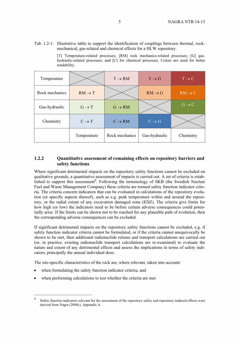
Tab. 1.2-1: Illustrative table to support the identification of couplings between thermal, rock-mechanical, gas-related and chemical effects for a HLW repository. .............. 5
Tab. 3.1-1: Potentially detrimental temperature-related (T) effects, assessment of their relevance, coupling to other rock-mechanical (RM), gas-related (G) or chemical (C) processes and treatment in, or omission from, the quantitative analyses in Chapter 4. ............................................................................................. 21
Tab. 3.2-1: Potentially detrimental rock-mechanical (RM) effects, assessment of their relevance, coupling to other temperature-related (T), gas-related (G) or chemical (C) processes and treatment in, or omission from, the quantitative analyses in Chapter 4. ............................................................................................. 25
Tab. 3.3-1: Potentially detrimental gas-related (G) effects, assessment of their relevance, coupling to other temperature-related (T), rock-mechanical (RM) or chemical (C) processes and treatment in, or omission from, the quantitative analyses in Chapter 4. ............................................................................................. 30
Tab. 3.4-1: Potentially detrimental chemical (C) effects, assessment of their relevance, coupling to other temperature-related (T), rock-mechanical (RM) or gas-related (G) processes and treatment in, or omission from, the quantitative analyses in Chapter 4. ............................................................................................. 39

NAGRA NTB 14-13 X
Tab. 4.1-1: Safety function criteria for the assessment of processes. ........................................ 41
Tab. 4.1-2: Criteria for the thermal effect on the host rock. ...................................................... 42
Tab. 4.1-3: Criteria for the thermally induced increase of porewater pressures. ...................... 43
Tab. 4.1-4: Criteria for the EDZ formation. .............................................................................. 44
Tab. 4.1-5: Criteria for the effects of the EDZ (and other processes in near field) on the buffer swelling pressure/density. ............................................................................ 45
Tab. 4.1-6: Criteria for the effect of the EDZ – convergence interaction. ................................ 45
Tab. 4.1-7: Criterion for gas-induced porewater displacement through host rock. ................... 46
Tab. 4.1-8: Criteria for gas pressure build-up. .......................................................................... 47
Tab. 4.1-9: Criterion for gas-induced porewater displacement through host rock. ................... 47
Tab. 4.1-10: Criteria related to chemical effects on the SF/HLW buffer and host rock. ............ 48
Tab. 4.5-1: Volumes of concrete and inventory of total OH- in concrete in a tunnel liner for a nominal 1 m length of tunnel. ........................................................................ 76
Tab. 4.5-2: Masses, volume percent and annular thicknesses of bentonite potentially altered by interaction with the steel canister over time using the mass balance defined by equation (3) and the rate of corrosion of steel from King (2008)...................................................................................................................... 78
Tab. 4.5-3: Masses, volume percent and annular thicknesses of bentonite potentially altered by interaction with a concrete tunnel liner for a nominal 1 m length of tunnel using the mass balance defined by equation (2) and noting that MX-80 bentonite contains 87 wt. % montmorillonite and that the initial volume of the buffer for 1 m tunnel length is 4.12 m3. ........................................... 80
Tab. A-1: Hydrogeological units of a generic siting area for a combined SF/HLW/ILW and L/ILW repository. .......................................................................................... A-2
Tab. A-2: Comparison of the given and implemented volumes with the corresponding adjustment of porosity and specific heat capacity. ............................................... A-7
Tab. A-3: Hydraulic and two-phase parameters for the different hydrogeological units and for the different underground facility components. ....................................... A-8

XI NAGRA NTB 14-13
List of Figures
Fig. 1.2-1: Methodological steps and the chapters of this report where each step is applied. ..................................................................................................................... 3
Fig. 2.1-1: Schematic illustration of the barrier systems for the different waste categories. ................................................................................................................. 9
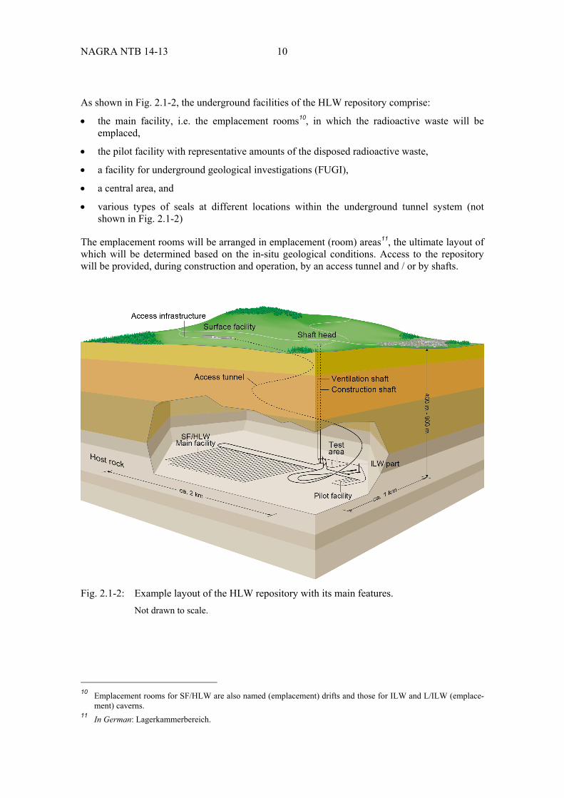
Fig. 2.1-2: Example layout of the HLW repository with its main features. ............................. 10
Fig. 2.1-3: The compartmentalisation concept adapted from Nagra (2011), for the case of emplacement of ~ 5 m long SF canisters. ........................................................... 12
Fig. 2.1-4: Cross section of a K09 LLW emplacement cavern after closure. ........................... 13
Fig. 3.1-1: Overview of the expected evolution of main processes in a HLW repository based on a compilation of modelling reports and experimental data. ..................... 17
Fig. 3.2-1: EDZ indicator criteria related to long-term safety. ................................................. 24
Fig. 4.2-1: 2D model geometry of a SF/HLW emplacement drift in the Opalinus Clay, with the 1D extention to the prescribed boundary conditions at the top (land surface) and at the bottom (crystalline). ................................................................. 51
Fig. 4.2-2: Vertical pressure profiles relative to lithostatic pressures for the repository depths considered (rows: top-600 m, middle-450 m, bottom-750 m) and for the two heat production rates (columns: left-average, right-maximum). ................ 53
Fig. 4.3-1: A conceptual framework for EDZ fracture closure in Opalinus Clay, covering the key phenomena and features from the early post-excavation phase until static formation pressure recovery. ...................................................... 55
Fig. 4.3-2: Typical fracture patterns around a SF/HLW drift under different in-situ stress conditions. ..................................................................................................... 57
Fig. 4.3-3: Basic features of the EDZ abstraction process for a circular tunnel: representative fracture patterns are simulated for relevant repository configurations with a discrete fracture network model. ......................................... 58
Fig. 4.3-4: Temporal evolution of axial hydraulic conductivity (K) of the EDZ around a backfilled emplacement drift. ................................................................................. 59
Fig. 4.3-5: Temporal evolution of the equivalent hydraulic conductivity of the EDZ. ............ 60
Fig. 4.3-6: Abstracted EDZ model, based on the reference simulation case HAA-01 FEMDEM (Table 4-1 in Geomechanica 2013). ..................................................... 61
Fig. 4.3-7: Radial profiles of (a) effective porosity and (b) effective hydraulic conductivity of 24 variant cases after recovery of static formation pressure (late times). ............................................................................................................. 63
Fig. 4.3-8: Relationship between equivalent EDZ radius and homogenised porosity (upper left) and hydraulic conductivity (upper right), in the case of a SF/HLW emplacement drift. .................................................................................. 64
Fig. 4.3-9: Relationship between equivalent EDZ radius and homogenised porosity (upper left) and hydraulic conductivity (upper right), in the case of a vertical shaft. ....................................................................................................................... 65
Fig. 4.4-1: Potential migration paths for corrosion gases accumulated in the SF/HLW emplacement drifts (after Nagra 2004). .................................................................. 66

NAGRA NTB 14-13 XII
Fig. 4.4-2: Implementation of SF/HLW emplacement drifts in the 2D rectangular grid for modelling the release of waste-generated gas in Opalinus Clay. ...................... 69
Fig. 4.4-3: Time history of gas pressure in the emplacement drift compared to 80 % of lithostatic pressure (onset of pathway dilation, dashed horizontal line) for depths of 600 m bgl. ............................................................................................... 71
Fig. 4.4-4: Time history of gas pressure in the emplacement drift compared to 80 % of lithostatic pressure (onset of pathway dilation, dashed horizontal lines) for repository depths of 450 (left) and 750 m bgl (right), respectively. ....................... 72
Fig. 4.4-5: Synthesis of simulation results: time history of the gas pressure in emplacement drifts relative to 80 % of lithostatic pressure at respective depths, in %; left: simulations with reference gas generation rate (solid lines), right: simulations with upper bound gas generation rates (dashed lines). ...................................................................................................................... 73
Fig. 4.5-1: Iron-bentonite interaction as a non-linear process. ................................................. 77
Fig. 4.5-2: A typical mineralogical alteration profile from a reaction – transport simulation of the interaction of a steel canister (right margin) and a 1 m thickness of MX-80 bentonite and a mudstone groundwater (left margin) at 100° C after different times. ................................................................................... 79
Fig. 4.5-3: Mineralogical profile across the concrete liner after about 30'000 years considering full (porosity) feedback on transport. .................................................. 80
Fig. 4.5-4: Porosity evolution at t = 0, 10 and 30.8 ka. ............................................................ 81
Fig. 4.5-5: Effect of an OPC concrete tunnel liner thickness on the thickness of alteration of bentonite. ............................................................................................ 82
Fig. A-1: Conceptual layout of a combined repository with the L/ILW cavern area and the SF/HLW/ILW emplacement area. .................................................................. A-3
Fig. A-2: Plan view of the nested integrated finite difference (IFD) mesh in the repository layer. .................................................................................................... A-4
Fig. A-3: Vertical XZ-section (top) with close-up of the L/ILW access tunnel and shaft with surrounding EDZ (bottom). .......................................................................... A-5
Fig. A-4: Plan view showing the different repository components in the repository horizon. ................................................................................................................. A-6
Fig. A-5: Vertical cross section in the YZ-section. .............................................................. A-6
Fig. A-6: The gas generation rates as a function of time for the different wastes. ............... A-9
Fig. A-7: Heat generation rate as a function of time from a MOX/U2 and a HLW canister. ................................................................................................................. A-9
Fig. A-8: Pressure distribution in the repository horizon at the end of Phase 3 (70 years). ........................................................................................................... A-11
Fig. A-9: Pressure distribution in the vertical section through the L/ILW cavern (at X coordinate = 510 m) at the end of Phase 3 (70 years). .............................. A-12
Fig. A-10: Gas saturation distribution in the plane of the repository horizon at the end of the Operational Phase 3 (70 years). .................................................................... A-12

XIII NAGRA NTB 14-13
Fig. A-11: Pressure histories in the repository components during the operational and post-closure phases for the simulation cases 1 to 4: (a) Case 1: resaturation without heat and gas generation, (b) Case 2: gas generation, (c) Case 3: heat generation, and (d) case 4: combined resaturation, heat- and gas generation. .... A-13
Fig. A-12: Case 4: Pressure distribution in the repository horizon 100 years (left) and 1'000 years (right) after the start of the post-closure phase. ............................... A-15
Fig. A-13: Pressure distribution in the repository horizon 10'000 years (left) and 100'000 years (right) after the start of the post-closure phase. ........................... A-15
Fig. A-14: Case 4: Pressure distribution in a vertical section through a SF/HLW emplacement drift 100 years (left) and 1'000 years (right) after the start of the post-closure phase. ........................................................................................ A-16
Fig. A-15: Case 4: Temperature distribution 100 years (above) and 1'000 years (below) after the start of the post-closure phase in a vertical section through a SF/HLW emplacement drift. .............................................................................. A-17


1 NAGRA NTB 14-13
1 Introduction
1.1 Background and aims
In Switzerland, the Nuclear Energy Law requires the disposal of all types of radioactive waste in deep geological repositories (KEG 2003). The Swiss Radioactive Waste Management Pro-gramme (Nagra 2008a and b) foresees two types of deep geological repository: a high-level waste repository (HLW repository) 2
for spent fuel (SF)3, vitrified high-level waste (HLW) and long-lived intermediate-level waste (ILW), and a repository for low- and intermediate-level waste (L/ILW repository) 4. The procedure for selecting the sites for the deep geological reposi-tories is specified in the concept part of the Sectoral Plan for Deep Geological Repositories5 (SGT, BFE 2008) and consists of three stages. The procedure ends with the registration of the selected site for each repository type in the SGT, following which General Licence Applications can be made.
For Stage 1 of the process, Nagra proposed six geological siting regions for the repository for L/ILW and three for the repository for HLW in November 2008 (Nagra 2008b). These siting proposals were prepared on the basis of criteria relating to safety and engineering feasibility, as well as other requirements set out in the SGT. It was noted for the three siting regions that were proposed for both the HLW and the L/ILW repositories that the two repository types could be co-located at the same site; the term used for such a facility is a 'combined repository'. The siting regions proposed by Nagra were entered in the SGT with a decision by the Federal Council in November 2011.
In Stage 2, proposals for siting the repository surface facility within the so-called planning peri-meters of the regions had to be prepared together with the siting regions and the affected Cantons for potential areas. Nagra put forward siting proposals for the surface facility at the beginning of Stage 2 and these then formed the basis for a discussion and cooperation with the regional participation bodies. The proposals were evaluated and reviewed by the regions and the Cantons during the course of Stage 2 and were also, upon their request, modified and supple-mented with additional proposals. As a result, Nagra was able to propose at least one siting area for the surface facility in each of the siting regions and to complete the associated planning stu-dies. These planning studies serve as the basis for the socio-economic-ecological impact studies for each region that are prepared under the lead of the Swiss Federal Office of Energy (SFOE)6 and for the preliminary investigations for the environmental impact assessment to be conducted at a later stage.
Stage 2 also includes a narrowing-down of the potential geological siting regions to at least two for each repository type for further investigation for Stage 3. This is done by conducting a safety-based comparison of the siting regions, with the highest priority being assigned to the long-term safety of the repository. A geological siting region can only be placed in reserve in Stage 2 if it shows clear disadvantages in terms of safety compared with the other regions. Aspects of spatial planning, ecology, economy and society are of secondary importance as selection criteria and the socio-economic studies have no impact on the selection of the geo-logical siting regions. Requirements for these safety analyses are set out in BFE (2008) and in ENSI 33/075 (ENSI 2010). The present report addresses the specific requirement that the long- 2 In German: HAA-Lager. 3 According to the current legislation, spent fuel is classified as radioactive waste. 4 In German: SMA-Lager. 5 In German: Sachplan geologische Tiefenlager (SGT). 6 In German: Bundesamt für Energie (BFE).

NAGRA NTB 14-13 2
term behaviour of the repository barrier system should be demonstrated. This includes an evalu-ation of the safety-related impact of repository-induced effects on the geological barrier (e.g. thermal effects, the formation of an excavation damaged zone, the effects of any high-pH plume and the effects of gas generation and gas pressure build-up). In ENSI 33/115 (ENSI 2011, Request #38), ENSI requires that these analyses address all potential host rocks in a site-specific manner.
The present report focuses on a HLW repository constructed in Opalinus Clay, which is the host rock proposed in Stage 1 and 2 of the SGT for this repository type. The aim of this report is to assess the effects of the radioactive waste emplaced in the repository and of the repository engi-neered materials on each other and more specifically on the Opalinus Clay host rock in order to better align the RD&D efforts of Nagra. A separate report deals with repository-induced effects for the L/ILW waste repository (Leupin et al. 2016). In the appendix of the present report repository effects of a combined repository is discussed. This is the reason why the L/ILW report is also discussed in some parts of the present report.
The repository-induced effects considered in this report are of the following broad types:
Thermal effects: i.e. effects on the host rock and engineered barriers arising principally from the heat generated by the waste; thermal effects can be assessed by measuring the state variables: temperature and heat flow
Rock-mechanical effects: i.e. effects arising from the mechanical disturbance to the rock caused by the excavation of the emplacement rooms and other underground structures; rock-mechanical effects can be assessed by evaluating the state variables: stress and strain
Hydraulic and gas-related effects7: i.e. the effects of repository resaturation and of gas generation, e.g. due to the corrosion of metals within the repository, on the host rock and engineered barriers; these hydraulic and gas related effects can be assessed by measuring the state variables: degree of saturation, specific flux and porewater pressure
Chemical effects: chemical interactions between the waste, the engineered materials and the host rock, but with a focus on chemical effects of the waste and engineered materials on the host rock. State variables that are indicative of chemical effects are: porewater composi-tion, mineralogy and porosity
For the barrier system to be acceptable, it needs to be shown that such effects will not adversely affect repository performance and safety.
Effects such as those due to any micro-organisms trapped in the repository are subsumed within the broad categories given above and discussed there accordingly.
The processes giving rise to repository-induced effects are described in detailed process reports. The descriptions given in the present report are thus limited to synopses and the reader is referred to the detailed process reports for further information. Furthermore, the main emphasis of the report is on repository-induced effects on the host rock, which are covered in more detail than effects on the engineered barriers in the following chapters. The datasets and indicator criteria used to assess the repository-induced effects were cleared in 2015 or before and thus might to some extent vary from the more site specific data and indicator criteria that will be cleared for Stage 3. The differences concern especially effects related to gas pressure build-up, rock-mechanics and thermal effects. The method developed in this status report will be reassessed in the course of stage 3 of the sectoral plan.
7 Hydraulic and gas-related effects are also referred to as "two-phase flow" phenomena in the text.

3 NAGRA NTB 14-13
1.2 Methodology
The methodology adopted in this report comprises the following broad steps and key questions (Fig. 1.2-1):
1. describe the reference repository configuration / design 2. identify and describe processes with potentially adverse effects on safety functions8 3. make a first qualitative assessment of these effects based on pre-existing data 4. if significant adverse consequences cannot be excluded on qualitative grounds, make a
quantitative assessment of these consequences, including, if necessary, radionuclide release and transport calculations
5. based on the insights from Steps 1 – 4, provide input to the design of the repository with the aim of avoiding, minimising or mitigating effects that may have a significant and detrimen-tal impact on repository safety
Fig. 1.2-1: Methodological steps and the chapters of this report where each step is applied. 8 The overall criterion for evaluating repository safety is the risk criterion issued by national regulators which is
usually expressed as a maximum dose, or risk, to a representative individual in the group in the biosphere exposed to the greatest risk. To evaluate the dose or risk from a repository a detailed and quantitative under-standing of all processes that affect the repository together with the associated uncertainties is needed. Dose and risk are therefore not very practical entities to use for the study of individual repository components. To resolve this, the concept of "safety functions" has been introduced. A safety function is a description of how an individual barrier contributes to the confinement and retardation of radionuclides. Safety functions can be defined based on the understanding of the properties of the components and the long-term evolution of the system.
Chapter 4
Process identification and description
yes
No furtherdiscussion
Chapter 3
Chapter 5
Repository site or repositoryconcept must be re-evaluated
Can the effect on the natural / technicalbarrier be conclusively addressed?
Quantitative assessment: can thesafety function indicators be met?
Can engineering options help tomitigate the effects?
yes
yes
no
no
no
Safety concept /safety functions
Reference repositoryconfiguration and design
Chapter 3
Step 3
Step 2
Step 4
Step 5
NAGRA NTB 14-13 4
In the following, Steps 2, 3 and 4 with the corresponding key questions are addressed in more detail.
1.2.1 Qualitative assessment of adverse consequences
The third step is a qualitative assessment of the specific impacts of the identified thermal, rock-mechanical, hydraulic- and gas-related, and chemical processes on the repository safety functions based on pre-existing data.
When assessing the potentially adverse consequences for the safety functions, current under-standing of these effects and all associated uncertainties are taken into account. Specific aspects that are assessed include:
the reversibility of any impact: if the impact of a process is reversible, then its adverse consequences are likely to be more limited than if it is irreversible
the relevant time period: some effects only occur for a limited time period (e.g. in the case of thermally induced effects, the period during which the waste generates significant heat) and, if radionuclides are fully contained during this period (and if the impacts are rever-sible), then there may be few if any consequences for repository safety
the spatial extent of any impact: some processes will be spatially limited, e.g. to the repository near field only, whereas others may propagate further into the repository host rock
the relevance to siting: given that an objective of SGT Stage 2 is to narrow down the number of geological siting regions for a HLW repository for further geological investiga-tions, any relevance of site-specific conditions to the adverse consequences of repository-induced effects is clearly of interest
It is important not only to consider direct (i.e. thermal, rock-mechanical, gas-related and chemi-cal) consequences of repository-induced effects, but also the couplings between these. Illustra-tive tables, such as that shown in Tab. 1.2-1, are used to support the identification of such coup-lings and promote comprehensiveness. The first letter indicates the repository-induced effect, which points with an arrow to the coupled effect. Such tables are presented and further elabora-ted in Chapter 3.
In some cases, it is possible to argue convincingly, on qualitative grounds, that the detrimental impacts of the processes on the repository safety functions will be negligible. In these cases, no further discussion is needed. In other cases, a more quantitative evaluation of consequences is necessary in Step 4 (see next section).
5 NAGRA NTB 14-13
Tab. 1.2-1: Illustrative table to support the identification of couplings between thermal, rock-mechanical, gas-related and chemical effects for a HLW repository. [T] Temperature-related processes; [RM] rock mechanics-related processes; [G] gas-hydraulic-related processes; and [C] for chemical processes. Colors are used for better readability.
Temperature T RM T G T C
Rock mechanics RM T RM G RM C
Gas-hydraulic G T G RM G C
Chemistry C T C RM C G
Temperature Rock mechanics Gas-hydraulic Chemistry
1.2.2 Quantitative assessment of remaining effects on repository barriers and safety functions
Where significant detrimental impacts on the repository safety functions cannot be excluded on qualitative grounds, a quantitative assessment of impacts is carried out. A set of criteria is estab-lished to support this assessment9. Following the terminology of SKB (the Swedish Nuclear Fuel and Waste Management Company) these criteria are termed safety function indicator crite-ria. The criteria concern indicators that can be evaluated in calculations of the repository evolu-tion (or specific aspects thereof), such as e.g. peak temperature within and around the reposi-tory, or the radial extent of any excavation damaged zone (EDZ). The criteria give limits for how high (or low) the indicators need to be before certain adverse consequences could poten-tially arise. If the limits can be shown not to be reached for any plausible path of evolution, then the corresponding adverse consequences can be excluded.
If significant detrimental impacts on the repository safety functions cannot be excluded, e.g. if safety function indicator criteria cannot be formulated, or if the criteria cannot unequivocally be shown to be met, then additional radionuclide release and transport calculations are carried out (or, in practice, existing radionuclide transport calculations are re-examined) to evaluate the nature and extent of any detrimental effects and assess the implications in terms of safety indi-cators, principally the annual individual dose.
The site-specific characteristics of the rock are, where relevant, taken into account:
when formulating the safety function indicator criteria, and
when performing calculations to test whether the criteria are met
9 Safety function indicators relevant for the assessment of the repository safety and repository-induced effects were
derived from Nagra (2008c), Appendix A.
NAGRA NTB 14-13 6
Thus, the model assumptions and parameter values that are used are intended to cover the full range of expected conditions in the potential siting areas for a HLW repository in Opalinus Clay. The expected conditions are therefore based, where possible, on site-specific field obser-vations and measurements, complemented by laboratory experiments, supporting calculations and, where necessary, expert judgement. Expert judgement is required because not all charac-teristics of the potential siting areas are well known at the present stage of the programme. Some assumptions may also be challenged by stakeholders. Thus, especially for less well known and potentially sensitive characteristics, some more extreme model assumptions and parameter values are considered that are outside the ranges expected at the potential siting areas but are still physically plausible, in addition to realistic assumptions and parameter values. The more extreme calculation cases can illustrate the robustness of the repository concept by showing that, even under highly pessimistic, hypothetical assumptions, the nature and extent of any detrimental effects are still insufficient to compromise safety. An example of this type of calculation is that of porewater flow and radionuclide transport along the EDZs of the repository tunnel system, assuming a hypothetically very high EDZ hydraulic conductivity, even though the expected evolution is that the EDZ, once formed, will reseal to some extent. The calculation is discussed further in Section 4.6.2, with details given in Poller et al. (2014).
Nagra's internal data clearance procedure was used to ensure the consistent use of parameter values in all model calculations. This data clearance procedure is an integral part of Nagra's Quality Management System and requires that the data user (client) sets out the data to be used and the purpose to which the data will be put. By signing off the data, the data producer con-firms that the data are suitable for their intended use. A data clearance committee oversees the application of this procedure.
1.2.3 Input to the design of the repository
If, based on the insights from Steps 1 – 4, repository-induced effects and associated processes are identified that could conceivably give rise to unacceptable impacts on the repository and its safety functions, then future iterations of the repository design should aim to avoid, minimise or mitigate these effects. Thus, the present study provides input to the repository design process.
1.3 Report structure and relation to other reports
The remaining chapters of this report are structured as follows:
Chapter 2 describes the reference configuration for a HLW repository in Opalinus Clay assumed in this report. This description includes the repository engineered and geological barriers, the safety functions that they perform, and the safety function indicators that are evaluated in the later chapters to assess the impact of repository-induced effects on the safety functions. Chapter 2 thus covers Step 1 of the methodology described above.
Chapter 3 identifies, and provides a qualitative description of thermal, rock-mechanical, gas-related and chemical repository-induced effects, including the couplings between them and, based on this description, provides a summary of the evolution of the repository, taking into account those effects that are judged to be potentially significant. Chapter 3 thus covers Steps 2 – 3 of the methodology described above.
Chapter 4 provides a quantitative assessment of those effects that are judged to be poten-tially significant, including the safety function indicator criteria used to judge actual signi-ficance, dose calculations of specific effects that cannot be excluded based on these criteria and a synthesis of system behaviour under site conditions. This chapter thus covers Step 4 of the methodology.

7 NAGRA NTB 14-13
Chapter 5 summarises the input that the present study provides to the repository-design pro-cess and provides, as a conclusion, input to the repository design process. This chapter thus covers Step 5 of the methodology.
The present report and the companion report on repository-induced effects in the context of a L/ILW repository (Leupin et al. 2016) refer to the findings documented in SGT Stage 2:
the main technical report for SGT Stage 2 (Nagra 2014a) provides the formal safety-related comparison of the repository siting regions currently under consideration
a geological synthesis (Nagra 2014b)
a safety report (Nagra 2014c)
a report on the operational risks (Nagra 2014d)
These reports, together with more detailed and specific process reports, provide the technical foundation for the present report.


9 NAGRA NTB 14-13
2 Description of the reference repository configuration and design
2.1 Repository concept
The post-closure safety of the HLW repository is ensured with a system of nested, passive engineered and geological barriers, which complement one another. The individual elements of the barrier system are the waste matrices, the disposal containers and canisters, the materials used for backfilling and sealing of the underground structures, the host rock plus other geo-logical formations that may additionally contribute to the confinement of radioactive materials (confining units).
Fig. 2.1-1 schematically illustrates the barrier systems for the different waste categories dis-posed of in the HLW and L/ILW repositories. In the following, the reference configuration for the HLW barrier system is described to the extent needed in the context of this report. More details on the engineered barriers and the emplacement procedures are reported in Nagra (2014d). The geological barriers are described in detail in Nagra (2014b).
Fig. 2.1-1: Schematic illustration of the barrier systems for the different waste categories. Not drawn to scale, geological profile with vertical exaggeration.
SF
Geological barriers Engineered barriers
ILW and L/ILW
Disposal canister
Backfilling and sealing
HLW
Disposal container
NAGRA NTB 14-13 10
As shown in Fig. 2.1-2, the underground facilities of the HLW repository comprise:
the main facility, i.e. the emplacement rooms10, in which the radioactive waste will be emplaced,
the pilot facility with representative amounts of the disposed radioactive waste,
a facility for underground geological investigations (FUGI),
a central area, and
various types of seals at different locations within the underground tunnel system (not shown in Fig. 2.1-2)
The emplacement rooms will be arranged in emplacement (room) areas11, the ultimate layout of which will be determined based on the in-situ geological conditions. Access to the repository will be provided, during construction and operation, by an access tunnel and / or by shafts.
Fig. 2.1-2: Example layout of the HLW repository with its main features. Not drawn to scale.
10 Emplacement rooms for SF/HLW are also named (emplacement) drifts and those for ILW and L/ILW (emplace-
ment) caverns. 11 In German: Lagerkammerbereich.

11 NAGRA NTB 14-13
On arrival at the surface facility of the repository, the radioactive materials to be emplaced will be in the following forms:
SF assemblies, each of which contains a large number of irradiated fuel rods (100 to 200). The fuel rods consist of stacks of cylindrical pellets contained in a zirconium alloy (Zirca-loy) cladding, along with other structural materials such as steel alloys. The pellets are com-posed of ceramic uranium oxide (UO2) or a blend of UO2 and PuO2 (MOX).
HLW, in which radionuclides are incorporated in a homogenous borosilicate glass matrix within a thin stainless steel fabrication flask.
ILW, with much lower activity than SF or HLW, embedded within a cementitious matrix or, in some cases, within a bitumen, polystyrene or borosilicate glass matrix. The waste matrix with the radionuclides is usually packed in steel drums and/or concrete containers. The emplacement caverns for ILW are essentially the same as those of a separate L/ILW repository (see e.g. Leupin et al. 2016).
In the surface facility, SF assemblies and fabrication flasks with vitrified HLW are loaded into disposal canisters, fabricated from carbon steel in the current reference design. The disposal canisters are about 5 (SF) and 3 (HLW) metres in length and about one metre in diameter. The average thermal output is 1'350 W at the time of closure of the repository whereas maximum heat output is 1'500 W (Senger et al. 2014). They have a wall thickness of about 14 cm. Other canister material options (Nagra 2016) are being evaluated (e.g. copper-coated canisters), but are not discussed further in this report, except to note that if options other than carbon steel were to be implemented, the repository-induced impacts related to gas production could be much smaller (e.g. in the case of copper). In this sense, it is conservative to consider the carbon steel reference design.
After transport to the underground facilities, the disposal canisters are emplaced in 300 to 600 m long, dead-end drifts, with an initial diameter of about 2.5 m. In the reference configuration, the canisters are emplaced coaxially within the drifts, requiring a pedestal of compacted bentonite blocks to support canisters prior to backfilling of the remaining spaces with highly compacted bentonite granules. The bentonite blocks and granules together form a protective mechanical and chemical buffer around the canisters. A spacing of ca. 3 m is foreseen between individual canisters, to limit the temperature increase in the surrounding buffer and rock due to heat generation in the canisters from radioactive decay.
The current repository concept, published in Nagra (2011), uses a cementitious liner to support walls of the emplacement rooms and access tunnels, designed to withstand the highest mechani-cal loads expected to arise during the construction and operational phases. To avoid any hydrau-lic shortcuts along the walls of the SF/HLW emplacement drifts that could arise from the degra-dation of the liner, and to comply with the principle of compartmentalisation, sealing sections comprised of granular and preformed bricks of buffer material are emplaced at regular intervals along the drifts, about one for every 10 canisters, to provide a hydraulic barrier. There is no liner where these sealing sections are emplaced, so that bentonite forms a watertight contact directly with the Opalinus Clay. The concept is illustrated in Fig. 2.1-3.
ILW is packed in concrete emplacement containers of standard size in the surface facility. After transport to the underground facility, the containers are stacked in dead-end emplacement caverns about 8 m in width and up to 200 m in length, which are supported by concrete liners (Fig. 2.1-4). The remaining void spaces are backfilled with specifically designed mortars and finally the caverns are sealed with a gas permeable sand-bentonite mixture and a cementitious abutment.

NAGRA NTB 14-13 12
The lower parts of the caverns ("cavities") are partitioned into disposal sections approximately 28 m in length by reinforced concrete walls ("bulkheads"). The void space between the disposal containers is filled with low-viscosity cementitious mortar (M2); the void spaces between the crane columns and between the disposal containers in the upper part of the room ("top headings") are filled with mono-grain cementitious mortar (M1, high viscosity mortar). The reference design for the ILW caverns is shown in Fig. 2.1-4.
The layout of the combined repository is described in Appendix A.
Fig. 2.1-3: The compartmentalisation concept adapted from Nagra (2011), for the case of emplacement of ~ 5 m long SF canisters. For HLW canisters the concept is the same but the HLW canisters are ~ 3 m long.
Compartmentalisation is provided by a hydraulic barrier at every 11th canister position. This hydraulic barrier is designed to prevent any lateral flow along the emplacement drift, which could otherwise occur through degraded cement liners used for stabilising the emplacement drift during the construction and operational phase.
8.35 m 5.35 m
1.6 m ca. 5.0 m
Intermediate seal (after every 11th canister)
2.5
m
2.8
-3.0
m
CA B
Steel archesHost rock (Opalinus Clay)
Bentonite pellets
Profile CProfile BProfile A
Shotcrete
Anchors(optional)
Intermediate sealHost rock
Bentonite pelletsShotcrete
Pedestal made of bentonite blocks
SF- Canisters
Longitudinal section
variable
variable

13 NAGRA NTB 14-13
Fig. 2.1-4: Cross section of a K09 LLW emplacement cavern after closure. The ILW emplacement caverns might be smaller with a cross section for 4 – 6 containers. Alternatively caverns might be conceived with a cross section for 7 or 5 drums (K06 and K04 respectively).
2.2 Safety concept and safety function indicators
Each element of a barrier system performs one or several long-term safety functions, which are (Nagra 2008c): physical isolation of the wastes from the human environment and long-term stability of the
barrier system confinement of radionuclides retarded release of radionuclides (after canister failure in the long-term) retention of radionuclides in the near field and geosphere (after canister failure in the long-
term) attenuated release of radionuclides to the environment (after canister failure in the long-
term)
Concrete
Mortar 1
Mortar 2
Concrete
Mortar 2
Lining
Filling Concrete
11.0 m
13
.2 m
Excavated Cross Section:
Outer Circumference:
123.6 m2
41.3 m
Waste
Mortar 1

NAGRA NTB 14-13 14
The overall geological situation ensures the long-term stability of the barrier system over the so-called time frame for safety assessment12, which is the main period of concern from the perspec-tive of post-closure safety and which was defined in Nagra (2008c) based on the decrease in radiological toxicity that occurs over time. It extends to one million years for the HLW reposi-tory.
The various elements of the barrier system that are key to providing these safety functions are (Nagra 2008c):
the deep underground location of the emplacement rooms that provides physical isola-tion of the wastes from the human environment over the time period to be considered
the geological setting that is not prone to geological events and processes affecting the long-term stability of the barrier system over the time period to be considered, and that is unlikely to attract human intrusion due to the absence of resources considered viable today or in the near future
the host rock and – where present – the confining units that provide low water flows, a fine and homogeneous pore structure and favourable geochemical conditions, thus pro-viding strong retention and attenuated release of radionuclides to the environment as well as a suitable hydrogeological, geochemical and geomechanical environment for the engineered barrier system over the time period to be considered
the buffer in the emplacement rooms that provides a well-defined interface between the disposal canisters and the host rock, strong retention of radionuclides and a suitable environment for the disposal canisters and the waste forms over the time period to be considered, and that is compatible with the favourable conditions in the host rock13
the backfill and sealing elements of the underground facility that prevent human access to the disposed wastes and that ensure mechanical stability of the underground structures, thus providing controlled conditions compatible with the favourable conditions in the host rock, as well as strong retention and attenuated release of radionuclides to the environment
the disposal canisters that ensure – in the case of SF and HLW – an absolute confinement of the wastes for several thousand years, and that contribute to retarded releases and strong retention of radionuclides even after breaching, due to the limited access of water and the favourable sorption capacity of corrosion products for many radionuclides
the waste forms that react only very slowly in the expected environment, ensuring low corrosion and degradation rates, and thus contribute to the confinement and retardation of releases for those radionuclides that are incorporated in the waste matrix
12 Also referred to as 'time period to be considered'. 13 At great repository depths or for tectonically strongly overprinted host rocks, a concrete liner may be required to
stabilise the emplacement rooms mechanically during construction and operation. In the longer term, this may lead to mineralogical alteration of the bentonite buffer and the host rock close to the interface with the concrete liner. The extent of such alteration zones both within bentonite and Opalinus Clay is expected to remain small (Savage 2013a). As a consequence, the contributions of the buffer and host rock to the safety functions are expected to remain essentially the same as for the case without concrete-lined emplacement rooms.

15 NAGRA NTB 14-13
These elements and the safety functions they provide must be shown to be robust with respect to repository-induced thermal, rock-mechanical, gas-related and chemical effects. In practice, this means that:
The temperature rise due to heat generated by the waste should be insufficient to adversely affect the transport and retention properties of the host rock and engineered barrier system (EBS).
The excavation damaged zone (EDZ) formed around underground openings should not lead to transport pathways with unacceptable properties.
Gas should be able to migrate without permanently damaging the transport and retention properties of the host rock. Furthermore, repository design options are available that reduce the gas-pressure build-up in the repository tunnel system.
The effects of canister corrosion products, the high-pH plume from cementitious materials and trapped oxygen on the host rock and EBS should be insignificant, and the materials used to stabilise underground openings should not be used in amounts that could compro-mise long-term safety.
The capacity of the system to meet these requirements is tested in the qualitative and quantita-tive assessments described in Chapters 3 and 4. These show, for example, that the maximum paleotemperature of the host rock is not exceeded indicating that geochemical processes detri-mental to its properties will not take place. The peak post-emplacement host-rock temperature is an example of a safety function indicator and the maximum paleotemperature of the host rock is an example of a safety function indicator criterion. As noted in Chapter 1, the criteria specify how high (or low) the indicators need to be before certain adverse consequences could poten-tially arise. If the criteria can be shown to be satisfied for all plausible paths of evolution, then the corresponding adverse consequences can be excluded. In the present example, if the criterion that the maximum paleotemperature should not be exceeded is satisfied, then thermally induced geochemical processes detrimental to host rock properties can be excluded.
Other safety function indicators considered in the following chapters include:
maximum temperature-induced pore-fluid pressure
maximum gas pressure
EDZ effective hydraulic conductivity and
extent of host rock above and below the repository that is not damaged by excavation
Criteria for these and other indicators are developed and applied in Chapter 4, Section 4.1.
In terms of the safety case, robustness is also enhanced by the fact that, if needed, design options are available to further reduce peak temperatures (although these may require con-siderable design or operational effort), to reduce the impact of the EDZ and reduce the gas-pressure build-up in the repository tunnel system. These options are discussed further in Chapter 5.


17 NAGRA NTB 14-13
3 Qualitative description of the repository-induced effects This chapter provides a qualitative description of the identified processes (Fig. 3.1-1) related to the four broad repository-induced effects (i.e. processes related to temperature evolution, pro-cesses related to rock mechanics, processes related to gas pressure build-up, and processes rela-ted to chemical interactions).
Fig. 3.1-1: Overview of the expected evolution of main processes in a HLW repository based on a compilation of modelling reports and experimental data.

NAGRA NTB 14-13 18
3.1 Processes related to temperature evolution and its effects on the repository system / evolution
3.1.1 Repository-generated heat
Decay heat from SF and HLW will increase temperatures within and around the repository for long periods of time. The maximum temperatures reached in the various disposal system com-ponents and the time dependency of the temperatures are determined principally by the heat out-put of the wastes, the selected repository layout, the thermal properties of the bentonite buffer and the surrounding rock (e.g. thermal conductivities and heat capacities) and the ambient tem-perature of the rock at repository depth.
The range of temperature within and around the SF/HLW near field depends on the thermal pro-perties of the buffer which are a function principally of its saturation state and of the ambient (site-specific) rock temperature. The development of the EDZ, which is also subject to uncer-tainty, will also affect thermal evolution (EDZ development is discussed in Section 3.2). Maxi-mum temperatures can be limited by decreasing canister heat output (e.g. by reducing canister loading and/or increasing the storage time of the SF / HLW prior to emplacement in the reposi-tory), increasing the spacing between canisters, increasing the spacing between emplacement drifts and/or decreasing the depth of the repository.
Heat in the ILW emplacement caverns is produced by hydration processes (Poller et al. 2014) and by radioactive decay of the waste. By the time of repository closure, the cement will be completely hydrated. The release of hydration heat from mortar used in plugs to close the repository and/or shotcrete used to stabilise underground structures would occur within a few months, leading to a relatively short-term temperature increase within and around the repository. It is expected that the temperature increase will be less than 5° C in the case of the ILW emplacement caverns due to the absence of large amounts of heat-emitting waste. The ambient temperature may range from about 38 – 55° C depending on the location (depth of the host rock) of the finally selected site. A temperature rise in the range of 5 to 10° C is expected to have a negligible effect on any chemical or physical processes.
On average, the decay heat per unit length of an ILW emplacement cavern is a small fraction of that of the SF/HLW emplacement drifts.
The specific temperature-related issues (for the HLW repository) highlighted in the following sections are the impacts of repository-generated heat on:
1. host rock and excavation damaged zone (EDZ)
2. bentonite buffer
3. rate of waste form degradation
4. corrosion rates of carbon steel
5. solubility and sorption of released radionuclides and
6. thermally induced overpressures
3.1.2 Impacts of repository-generated heat on the host rock
Heat generated by the SF and HLW canisters could, in principle, lead to irreversible structural changes in the host rock. However, the host rock has been subjected to much higher tempera-tures during its burial history than the present-day ambient temperature. Reconstruction of the

19 NAGRA NTB 14-13
burial history indicates maximum temperatures of about 80 – 90° C (e.g. Mazurek et al. 2006). Thus, if it can be ensured that the peak temperature of the rock does not significantly exceed the maximum value attained during its burial history, no significant irreversible structural changes are expected. The short time frame of the post-emplacement thermal transient (several hundred years), as compared with elevated temperatures persisting over millions of years during burial, reinforces this argument.
The initial temperature increase during the first decades after the emplacement of SF and HLW canisters nonetheless gives rise to a transient increase of pore pressure and rock stress, together with thermal expansion of the rock14. The implications of these rock-mechanical effects are dis-cussed in Section 3.2. Evaporation and partial desaturation of the host rock due to ventilation during the construction and operation phase, which is affected by repository generated heat, leads to various chemical effects on the host rock, as described in Section 3.4.1. The thermal pulse may also lead to further evaporation prior to eventual resaturation. However, examples from underground rock laboratories show that, even after several years, the zone of partial desaturation due to ventilation only extends to a depth of < 1 m from the tunnel walls, and it is unlikely that the additional heat from radioactive decay greatly increases the depth of the desaturated zone (Bossart & Nussbaum 2007).
3.1.3 Impacts of repository-generated heat on EDZ properties
The thermal pulse from the SF and HLW canisters may affect the mechanical evolution of the EDZ surrounding the emplacement drifts. The EDZ development is discussed in Section 3.2.1. It could also lead to the precipitation of sulphate and carbonate minerals within the EDZ (see Section 3.4).
3.1.4 Impacts of repository-generated heat on the bentonite buffer
Maintaining the swelling properties and plasticity of at least the outer part of the bentonite barrier around SF and HLW canisters is considered to be important in relation to its function of providing a low permeability diffusion barrier around the canisters and providing a degree of swelling to limit the deformation of Opalinus Clay surrounding the excavations, and hence limit EDZ formation. There are several chemical processes that might reduce both the swelling and the plasticity of bentonite buffer over time, all of which show a temperature dependency. These chemical processes are discussed in Section 3.4.
3.1.5 Impacts of repository-generated heat on waste form degradation
Data on the dissolution rates of SF and HLW are generally satisfactory up to about 100° C. Thus, assuming that canister breaching occurs sometime after about 10'000 years, the laboratory data should be relevant and adequate. In the case of SF, it is known that UO2 is thermodynami-cally stable and insoluble (solubility < 10-9 mol/l) under reducing conditions (Parks & Pohl 1988) and temperatures well above 100° C. Thus, earlier canister breaching is unlikely to accelerate dissolution. The specific dissolution rate of vitrified HLW is well known for tem-
14 Note: increased temperature causes both the pore fluids and rock matrix to expand. The partial restraint of the
rock mass and the difference in thermal expansion coefficients between fluid and rock cause differential expan-sion between the fluids and the rock. This differential expansion tends to cause fluid pressures to rise as the fluids tend to expand more than the net porosity change in the rock allows, for a given temperature change. This local pressure change causes fluid movement, but also a feedback to the rock stress state through hydro-mechanical coupling via effective stress.
NAGRA NTB 14-13 20
peratures up to about 100° C (Frugier et al. 2008). The HLW glass will be fractured due to ther-mal stresses during cooling, and this is taken into account in assessing the degradation rate of this waste form following canister breaching.
3.1.6 Impacts of repository-generated heat on the corrosion rates of carbon steel
Data on steady-state corrosion rates of carbon steel for temperatures up to 90° C in saturated and anaerobic conditions do not indicate any increase in the long-term corrosion rate relative to that at 25° C (Diomidis 2014). The data suggest that higher quality protective films form at higher temperatures, which may compensate for the increase in thermally activated transport rates in the protective film (King 2008).
3.1.7 Impacts of repository-generated heat on solubility and sorption of released radionuclides
Much of the data in the thermodynamic database used to evaluate solubilities and sorption in the near field are for a temperature of 25° C. Examination of temperature dependencies of equili-brium constants suggests that estimated solubility ranges may be valid up to ~ 50° C (Berner 2014). Thus, this represents a prudent design limit for maximum temperatures in the EBS and host rock at the time of canister breaching. The temperature dependency of sorption onto clay minerals is not well known. Literature data on oxide systems suggest some increase in sorption for most safety-relevant nuclides, at least up to 80° C. This may, however, be counterbalanced by the slight drop in pH expected at elevated temperatures.
Preliminary work at Nagra in which solubility limits are omitted in safety calculations indicates that there is little impact on overall calculated dose rates for a repository in Opalinus Clay. Thus, the requirement for improved assessment of thermal effects on properties such as solubi-lity should not be overstated. Nonetheless, there would be some benefit in extending such data to higher temperatures, at least to re-evaluate the range of values used as input to safety calcula-tions.
3.1.8 Summary of potentially detrimental effects due to couplings between temperature evolution and other processes
The potentially detrimental temperature-related effects identified in the preceding sections are summarised in Tab. 3.1-1, together with an assessment of their relevance, coupling to other rock-mechanical, gas-related or chemical processes and their treatment in, or omission from, the quantitative analyses in Chapter 4.
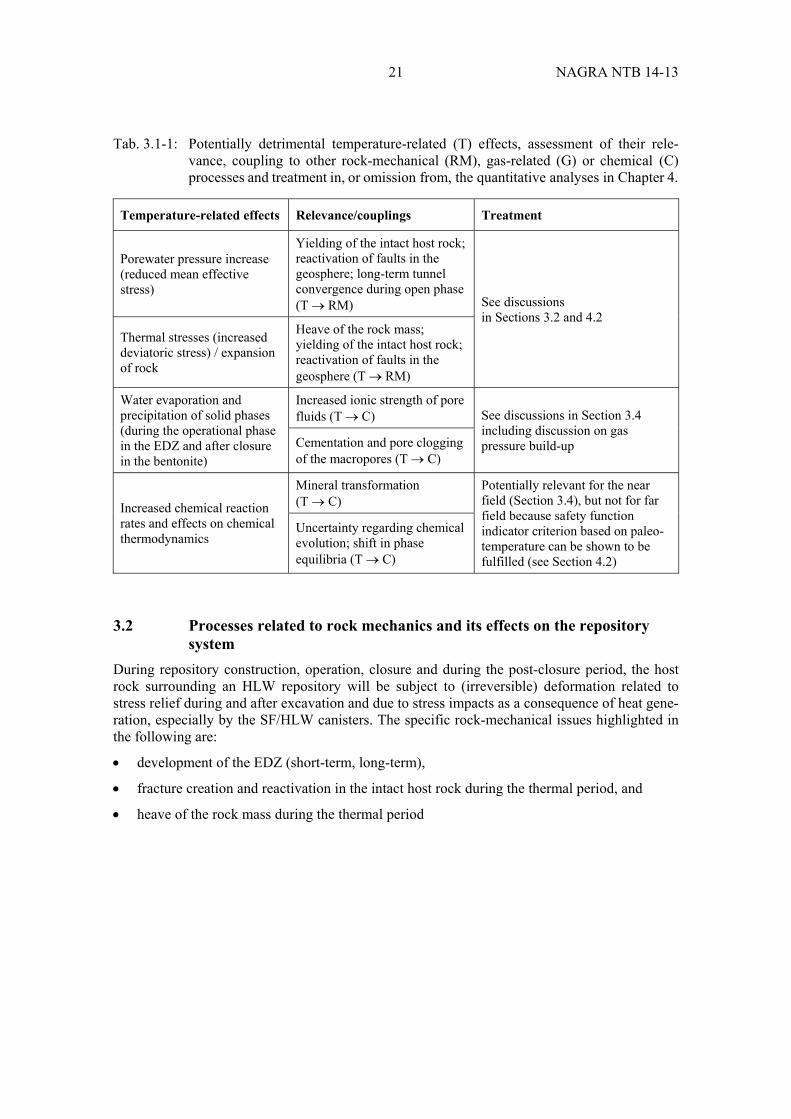
21 NAGRA NTB 14-13
Tab. 3.1-1: Potentially detrimental temperature-related (T) effects, assessment of their rele-vance, coupling to other rock-mechanical (RM), gas-related (G) or chemical (C) processes and treatment in, or omission from, the quantitative analyses in Chapter 4.
Temperature-related effects Relevance/couplings Treatment
Porewater pressure increase (reduced mean effective stress)
Yielding of the intact host rock; reactivation of faults in the geosphere; long-term tunnel convergence during open phase (T RM) See discussions
in Sections 3.2 and 4.2 Thermal stresses (increased deviatoric stress) / expansion of rock
Heave of the rock mass; yielding of the intact host rock; reactivation of faults in the geosphere (T RM)
Water evaporation and precipitation of solid phases (during the operational phase in the EDZ and after closure in the bentonite)
Increased ionic strength of pore fluids (T C) See discussions in Section 3.4
including discussion on gas pressure build-up Cementation and pore clogging
of the macropores (T C)
Increased chemical reaction rates and effects on chemical thermodynamics
Mineral transformation (T C)
Potentially relevant for the near field (Section 3.4), but not for far field because safety function indicator criterion based on paleo-temperature can be shown to be fulfilled (see Section 4.2)
Uncertainty regarding chemical evolution; shift in phase equilibria (T C)
3.2 Processes related to rock mechanics and its effects on the repository system
During repository construction, operation, closure and during the post-closure period, the host rock surrounding an HLW repository will be subject to (irreversible) deformation related to stress relief during and after excavation and due to stress impacts as a consequence of heat gene-ration, especially by the SF/HLW canisters. The specific rock-mechanical issues highlighted in the following are:
development of the EDZ (short-term, long-term),
fracture creation and reactivation in the intact host rock during the thermal period, and
heave of the rock mass during the thermal period

NAGRA NTB 14-13 22
3.2.1 Development of the EDZ
The excavation damaged zone (EDZ) around the backfilled underground structures of a geo-logical repository represents a viable release path for radionuclides as well as a possible escape route for corrosion and degradation gases. The efficiency of this release path depends on the shape and extent of the EDZ15 (see Fig. 3.2-1).
Excavation of tunnels, drifts and caverns in the host rock leads to stress redistribution and to micro- and macro-scale fractures within the EDZ. The formation of the EDZ is associated with an increased porosity, thus leading to a higher hydraulic conductivity, gas permeability and thermal conductivity, and a lower gas entry pressure around the emplacement rooms, sealing zones and other underground structures.
The EDZ adjacent to the emplacement drifts becomes partially de-saturated as a result of eva-poration due to ventilation during the construction and operation phase and due to the heat generated by the SF and HLW. The stress re-distribution in response to the excavation process causes the short-term convergence of the emplacement drifts. The ventilation regime during the operational period controls the long-term convergence. Desaturation increases the effective stress in the EDZ due to increasing suction and results in stiffening of the host rock. Unstable ventilation conditions could create cyclic deformations and thus promote the weakening of the rock and cause ongoing convergence ("creep"). Good operational procedures and tunnel supporting structures can successfully avoid these phenomena of cyclic creeping.
The hydraulic conductivity of the EDZ after the closure of the repository depends on the size, geometry and orientation of the excavation, as well as on the stiffness, self-sealing capacity and strength of the host rock and on the in-situ stress conditions. Evidence from experimental work at the Mont Terri Underground Rock Laboratory (URL) and the results of numerical analyses indicate that, in the case of SF/HLW emplacement drifts, the combined effects of the swelling pressure of the bentonite buffer and the self-sealing capacity of the Opalinus Clay will limit the effective hydraulic conductivity and gas permeability of the EDZ (the evolution of the EDZ is, however, potentially affected by chemical processes that could impact the swelling pressure of the buffer; see Section 3.4). Furthermore, tunnel support (e.g. cement liner, anchors etc.) will be used during construction of the emplacement drifts to limit the radial propagation of EDZ fractures.
The temperature evolution of the repository could also affect, and be affected by, the EDZ development. Understanding of the EDZ development during thermal loading has been acquired from studies of comparable rock formations and from several heater test experiments in the Mont Terri URL (Wileveau 2005, Gaus et al. 2012, Johnson et al. 2014).
15 The long-term safety criteria according to Tab. 4.1-4 are repeated here (Fig. 3.2-1):
The maximum hydraulic conductance of the EDZ after backfilling of the repository. Dose calculations suggest (Nagra 2014c), that the radionuclide transport in the EDZ of the backfilled repository structures is not significant, when the effective hydraulic conductivity of the EDZ is 10-8 m/s (corresponding to an equivalent thickness of the EDZ of 0.7 m), or that the product of EDZ area, AEDZ, and hydraulic conductivity, KEDZ, should be less than about 10-8 m3/s, or KEDZ should be less than 10-11 m/s.
The increase in pore volume of the plastified zone (EDZ). From a long-term safety perspective, the newly created pore volume of the damaged zone around the HLW emplacement drifts AEDZ × (nEDZ-nOPA)∙length should not exceed 0.5 m3/Tm (see discussion in Section 4.1).
The extent and shape of the plastified zone (EDZ). From a long-term safety perspective (Nagra 2014c), the plastified zone may not reduce the thickness of the intact host rock to less than 35 m, in which case its safety function as a transport barrier for radionuclides would be markedly reduced.
23 NAGRA NTB 14-13
Initially, at the time of waste emplacement, the radial stress at the wall of the backfilled emplacement drift is zero (for an unlined drift), the pore pressures are atmospheric (or even negative when relative humidity in the tunnel is < 1), while the tangential stresses may be elevated, depending on the size of the yielded zone (EDZ). Heating may cause a further increase in the tangential stress due to restrained thermal expansion of the rock mass. This may be associated with an extension of the EDZ and progressive disintegration of the rock mass in the EDZ (see Section 3.2.2). At the same time, the radial stress at the wall of the emplacement drifts builds up, leading to an increase in the mean effective stress. In the heater experiment (HE) at Mont Terri, no damage to the host rock close to the borehole wall was observed after the heating period (increase in host rock temperature was only about 20° C at 0.5 m distance from the bore-hole wall; Bossart & Nussbaum 2007).
It should be noted that a temperature increase may lead to EDZ growth, but it may also accele-rate self-sealing due to temperature-dependent restructuring of the rock fabric ("disintegration"). Insight into EDZ development during heating of a backfilled tunnel has been acquired in the Mont Terri research programme (PEBS/HE-E). Furthermore, comprehensive TH(M-) model analyses were conducted to assess the impact of the heating period on the EDZ and the host rock, respectively (Senger et al. 2014, Rudquist et al. 2013). Stress path analyses of the rock mass in the tunnel near field suggest that yielding of the rock is not to be expected in the EDZ, because the enhanced hydraulic conductivity of the EDZ prohibits the development of thermally induced porewater overpressures in this zone.
The EDZ is relevant to the repository safety functions because, if sufficiently conductive, it could provide a pathway for groundwater flow, gas flow and radionuclide transport, by-passing the undisturbed host rock and the sealing zones. In the case of ILW, because of the high poro-sity of the mortar that is used as backfill for the emplacement caverns, the hydraulic conducti-vity of the EDZ is not expected to affect overall radionuclide transport along the caverns. The EDZ is thus potentially more significant for SF/HLW. However, because of the low hydraulic conductivity of the EDZ by the time when any radionuclide release occurs, and also because of the low capacity of the tight, undisturbed host rock to supply water, the dead-end geometry of the emplacement drifts and the planned compartmentalisation of the SF/HLW drifts if a liner is used, no significant advective radionuclide transport in the axial direction is expected (see Fig. 2.1-3 and the associated text).
The EDZ may provide a reservoir within which repository-generated gas will accumulate (see Section 3.3). Furthermore, during the resaturation of the near field, it is conceivable that, due to the increased temperatures in the near-field rock, sulphate and carbonate minerals might precipi-tate in the EDZ fractures. Microorganisms may also be locally active within the EDZ. These effects are discussed in Section 3.3.4.
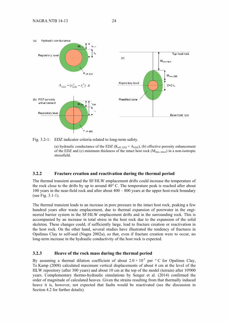
NAGRA NTB 14-13 24
Fig. 3.2-1: EDZ indicator criteria related to long-term safety. (a) hydraulic conductance of the EDZ (Keff, EDZ × AEDZ), (b) effective porosity enhancement of the EDZ and (c) minimum thickness of the intact host rock (Mmin, intact) in a non-isotropic stressfield.
3.2.2 Fracture creation and reactivation during the thermal period
The thermal transient around the SF/HLW emplacement drifts could increase the temperature of the rock close to the drifts by up to around 40° C. The temperature peak is reached after about 100 years in the near-field rock and after about 400 – 800 years at the upper host-rock boundary (see Fig. 3.1-1).
The thermal transient leads to an increase in pore pressure in the intact host rock, peaking a few hundred years after waste emplacement, due to thermal expansion of porewater in the engi-neered barrier system in the SF/HLW emplacement drifts and in the surrounding rock. This is accompanied by an increase in total stress in the host rock due to the expansion of the solid skeleton. These changes could, if sufficiently large, lead to fracture creation or reactivation in the host rock. On the other hand, several studies have illustrated the tendency of fractures in Opalinus Clay to self-seal (Nagra 2002a), so that, even if fracture creation were to occur, no long-term increase in the hydraulic conductivity of the host rock is expected.
3.2.3 Heave of the rock mass during the thermal period
By assuming a thermal dilation coefficient of about 2.0 × 10⁻⁵ per ° C for Opalinus Clay, Te Kamp (2008) calculated maximum vertical displacements of about 4 cm at the level of the HLW repository (after 300 years) and about 10 cm at the top of the model (terrain) after 10'000 years. Complementary thermo-hydraulic simulations by Senger et al. (2014) confirmed the order of magnitude of calculated heaves. Given the strains resulting from that thermally induced heave it is, however, not expected that faults would be reactivated (see the discussion in Section 4.2 for further details).

25 NAGRA NTB 14-13
3.2.4 Summary of potentially detrimental effects due to couplings between rock-mechanical processes and other processes
The potentially detrimental rock-mechanical effects identified in the preceding sections are summarised in Tab. 3.2-1, together with an assessment of their relevance, coupling to other temperature-related, gas-related or chemical processes and their treatment in, or omission from, the quantitative analyses in Chapter 4.
Tab. 3.2-1: Potentially detrimental rock-mechanical (RM) effects, assessment of their rele-vance, coupling to other temperature-related (T), gas-related (G) or chemical (C) processes and treatment in, or omission from, the quantitative analyses in Chapter 4. Note: chemical effects of H2 are dealt with in Section 3.4.
Rock-mechanical effects Relevance/couplings Treatment
EDZ creation
EDZ provides a potential pathway for groundwater flow, gas flow and radionuclide transport; EDZ reduces the thickness of the intact host rock barrier (RM G)
Taken into account in analyses of gas production and transport in Section 4.3 and 4.4
Various chemical and microbio-logical processes may occur within the newly created pore-space of the EDZ (RM C)
See Section 3.4
EDZ will have different thermal properties in comparison to the undisturbed host rock, affecting temperature evolution, especially around SF/HLW emplacement drifts (RM T)
Taken into account in analyses of repository temperature evolution in Section 4.2
Tunnel convergence
Tunnel convergence will affect the compliance with the design specifications for the SF/HLW emplacement drifts and seal sections respectively
See Sections 4.1 and 4.6.2
Fracture creation and reactivation during the thermal period
Even if fracture creation were to occur, no long-term increase in the hydraulic conductivity of the host rock is expected
See Sections 3.2.2 and 4.2
Heave of the rock mass during the thermal period
10 cm heave at ground surface has no long-term safety implications
See Sections 3.2.3 and 4.2

NAGRA NTB 14-13 26
3.3 Processes related to the gas pressure build-up and its effect on the repository system
The accumulation and release of repository-generated gases may affect a number of processes that influence long-term safety. The specific issues highlighted in the following are:
gas production in the backfilled repository emplacement rooms
impacts of gas accumulation on the repository near field
role of the EDZ as a gas release path
impacts of gas accumulation and gas release on the host rock
3.3.1 Gas production in the backfilled emplacement rooms
Gases are expected to be generated in a HLW repository as a result of anaerobic corrosion of metals (which produces H2), degradation of organic matter (which may produce gaseous compounds such as CO2 and CH4, which may incorporate 14C) and radiolysis of water (which principally produces H2). Metal corrosion (including the associated consumption of water) and organic and microbial activity in ILW emplacement caverns are discussed in Section 3.4.
The amount of gas generated corresponds directly to the waste inventory (SF/HLW disposal canisters, ILW) and to structural materials associated with tunnel construction and repository operation (rock support: anchors, bolts, arches, steel mats, steel fibres; waste emplacement: rails, track beds, lifting devices). Correspondingly, gas production takes place predominantly on the surfaces of the canisters and waste materials and at the interface between backfilled tunnels and host rock. Gas production rates are largely determined by the nature of the canister mate-rials and wastes to be disposed and the tunnel support materials, as well as by the environmental conditions and the porewater chemistry.
In the SF/HLW emplacement drifts, H2 gas production under anaerobic conditions typically occurs under fully or partially water saturated conditions (corrosion starts at relative humidity of about 60 % depending on surface roughness and salt deliquescence (Landolt et al. 2009). A free gas phase develops when the local solubility limit of the gas is exceeded, which is associated with a distinct volume increase and a concomitant build-up of gas pressures. In the case of ILW, because of the highly porous backfill material (mortar), the emplacement drifts will saturate relatively slowly and water saturation will take place preferentially in the lower part of the cavern. Anaerobic conditions will develop in partially saturated conditions due to the consump-tion of O2 by aerobic corrosion and other processes. As H2 gas is produced, it will mix with the remaining air and accumulate in the upper part of the cavern in the high-permeability mortar.
A balanced assessment of the aforementioned processes associated with gas generation requires a detailed evaluation of the environmental conditions for a given repository configuration. Not only the type of repository, but also the site-specific hydraulic conditions (rock permeability, formation pressure) and the porewater chemistry govern the impact of the relevant processes on the long-term evolution of the repository system (see Section 3.4).
3.3.2 Impacts of gas accumulation on the repository near field
In the SF/HLW emplacement drifts, gas generation processes at the canister surfaces and along the liners may delay the saturation of the buffer. During the early post-closure period, a satura-tion front develops due to the steep pressure gradient for liquid flow into the low-permeability,
27 NAGRA NTB 14-13
high-suction bentonite material, resulting in early saturated conditions around the liner with the embedded construction metals. At the same time, anaerobic conditions can be created locally due to oxygen consumption from aerobic corrosion. Hence, localised anaerobic conditions can co-exist temporarily with domains where oxidising conditions prevail. Hydrogen gas pressure build-up in the near field could affect corroding canisters by increasing the hydrogen absorption in the metal. However these effects can be considerably reduced by an appropriate choice of alloy for the canister and welding technique (Turnbull 2009).
Soon after waste emplacement, all flow and transport processes in the SF/HLW near field take place under non-isothermal conditions, with a significant temperature increase (> 100° C) due to heat generation associated with radioactive decay of waste material (SF/HLW). This affects the saturation behaviour of the bentonite buffer, as porewater is evaporated and transported away by vapour diffusion into cooler regions, where the vapour condenses creating a counter flow of liquid water towards the canister (see Section 3.1). At late times, after failure of the SF/HLW canisters and when the buffer around the canisters is saturated, the gas pressure may exceed the hydrostatic pressure and gas bubbles may form within the bentonite. In this case, the presence of trapped gas reduces the effective diffusion coefficient of the bentonite. This effect has no impli-cations for the diffusion of radionuclides after failure of the canister because the near field is expected to be saturated after the non-isothermal period.
The impact of gas accumulation in the ILW emplacement caverns is similar to that in the L/ILW emplacement caverns, as described in Leupin et al. (2016). Gas migration from the waste con-tainers mainly takes place through the high-permeability mortar in an upward direction towards the ceiling and laterally towards the cavern seal. Separation walls in the base of the emplace-ment caverns are designed to restrict liquid flow and transport of dissolved radionuclides along the cavern towards the cavern seal. Volatile radionuclides (mainly 14C) would be dispersed in the gas phase, which accumulates in the ceiling of the cavern. Restriction of gas flow could occur along the contact between the emplacement cavern and the surrounding host rock and along the contact between the cementitious backfill and the sand/bentonite seal. This is due to the hydrochemical self-sealing processes associated with chemical reactions of high-pH pore-water with clay minerals (backfill/seal interface) and clay porewater with cement (host-rock/liner interface) (see Section 3.4).
In the case of the ILW emplacement caverns, the specially designed mortar used as backfill pro-vides a much higher amount of pore volume that can be occupied by gas than in the case of the compacted bentonite in the SF/HLW emplacement drifts. However, in both cases, combined flow of gas and porewater takes place in the buffer/backfill. Various transport mechanisms con-trol this process, such as advection and diffusion of dissolved gas, visco-capillary displacement of porewater and dilatancy-controlled gas flow at elevated gas pressures. Independent of the actual gas transport mechanism, combined flow of gas and water through the bentonite buffer and through the sand/bentonite seal of the ILW emplacement caverns is associated with locali-sation phenomena, such as capillary fingering and pathway dilation (pathway dilation may also occur from excess pore pressures developed during the early thermal phase; see Section 4.2).
The ILW emplacement caverns seal, composed of a mixture of 80 % sand and 20 % bentonite, is designed to allow preferential flow of gas, while restricting liquid flow and transport of dis-solved radionuclides. The sand/bentonite mixture has a relatively low water retention, but gas can still be trapped in irregular patterns in the intergranular pore space of the sand/bentonite which may delay the consolidation process and affect the homogenisation of the seal during the resaturation process. Trapped gas facilitates gas migration through the sand/bentonite mixture creating continuous gas paths through the cavern seal.

NAGRA NTB 14-13 28
3.3.3 The role of the EDZ as a gas release path
An EDZ develops around all underground structures during repository construction and sub-sequent ventilation during the repository operation (Section 3.2). After backfilling of the under-ground structures, the EDZ re-compacts partially according to the local stress conditions and the swelling capacity of the backfill materials and of the near-field host rock.
Around the SF/HLW emplacement caverns, the EDZ is affected by the non-isothermal condi-tions at early times, resulting in an accelerated re-compaction due to thermal expansion of the host rock. With time, however, gas pressure build-up in the near field could give rise to the re-opening of the EDZ fractures. Continuous gas paths along the EDZ towards the backfilled access and operations tunnels can potentially be formed by coalescence of the re-opened EDZ fractures.
Hence, the EDZ may play a significant role as an additional gas storage volume and a release path for gas, which slows down the pressure build-up in the near field (e.g., Alcolea et al. 2014). Preferential gas pathways may develop in the EDZ. These gas-filled pathways may host sulphate reducing bacteria, leading to the production of sulphide which may diffuse into the bentonite and increase the canister corrosion rates. These potential effects are considered in the assessment of canister corrosion rates (Section 3.4).
At late times, when all the steel has corroded and gas production has declined, the gas pressure declines and effective stress on the fractures increases. However, the gas permeability of the EDZ is expected to remain higher than in undisturbed rock (Section 3.4).
The backfill in the ILW repository has high gas permeability; additionally the EDZ around the access tunnels may also provide a relevant gas pathway.
3.3.4 Impacts of gas accumulation and gas release on the host rock
Gas migration into the intact host rock can occur when the gas pressure exceeds the gas entry threshold pressure of the intact formation and overcomes the resistance to flow due to the relatively low effective gas permeability of the host rock. Gas pathways can form in the micro-scopic pore space of the intact host rock by porewater displacement. The relatively large surface area of the potential radial gas propagation front allows for diffusive transport of dissolved gas into the intact host rock. As the pore pressure declines in the host rock after the peak pressure has been reached in the emplacement rooms, the solubility limit decreases and exsolution of dis-solved gas can occur, which reduces the effective water permeability of the rock (gas entrap-ment in the host rock). Thus the invaded pore system of the intact host rock acts as an additional gas storage volume that reduces the gas overpressures in the emplacement rooms.
However, the porewater displaced from the near field will migrate into the host rock, thereby increasing the porewater pressure and the corresponding gas threshold pressure of the intact host rock. The increase in gas pressure causes a decrease in the effective stress in the host rock, which can create localised deformation and changes in pore volume, namely by fracture reacti-vation or by the creation of new pathways (pathway dilation). This may produce preferential gas pathways that could potentially also act as preferential transport paths for dissolved radio-nuclides released after canister failure. Although these paths are expected to close once gas flow ceases – even if long-lasting H2 fluxes over 100's ka along preferential flow paths locally affected rock properties, the self-sealing capacity of the rock would not be impaired because the stress in the rock would close the paths – transmissive paths are included in illustrative safety assessment calculations (Nagra 2010).
29 NAGRA NTB 14-13
The geochemical impact of H2 as electron donor for oxidised species present in the near field (sulphate, nitrate, ferrous iron) could result in local changes of the porewater chemistry and mineral composition of the host rock. For kinetic reasons, not all thermodynamically possible reactions are actually expected to occur under repository conditions, e.g. the abiotic production of CH4 from reduction of carbonate minerals or CO2 by H2. Microbial utilisation of hydrogen may occur where sufficient space and water activity is available.
Truche et al. (2009) showed that sulphate is more easily reduced by hydrogen, but the extrapola-tion of experiments conducted at 250 – 280° C led to a sulphate half-life at 90° C of approxi-mately 210 ka, thus it is not expected to be relevant in the performance assessment of a geological repository.
Truche et al. (2010) investigated sulphur species at lower oxidation states, such as pyrite which is thermodynamically unstable in the presence of H2. Pyrite reacts with H2 whereby pyrrhotite or troilite and H2S are produced. Under undisturbed in-situ conditions H2S is expected to precipi-tate with soluble Fe(II) to form FeS2. In Opalinus Clay, the amount of pyrite that could poten-tially react with H2 is limited. Traber & Blaser (2013) give a range of 1 – 3 %. It is thus not expected that the interaction between hydrogen and pyrite within the host rock would have any measurable impact on safety.
3.3.5 Summary of potentially detrimental effects due to couplings between gas-related processes and other processes
The potentially detrimental gas-related effects identified in the preceding sections are summa-rised in Tab. 3.3-1, together with an assessment of their relevance, coupling to other tempera-ture-related, rock-mechanical or chemical processes and their treatment in, or omission from, the quantitative analyses in Chapter 4.

NAGRA NTB 14-13 30
Tab. 3.3-1: Potentially detrimental gas-related (G) effects, assessment of their relevance, coup-ling to other temperature-related (T), rock-mechanical (RM) or chemical (C) pro-cesses and treatment in, or omission from, the quantitative analyses in Chapter 4. Note: chemical effects of H2 are dealt with in Section 3.4.
Gas-related effects Relevance/couplings Treatment
Gas pressurisation and gas-induced porewater displacement
Could lead to delayed resatura-tion and uncertainty in the thermo-hydraulic evolution of the near field, including duration
Taken into account in analyses in Sections 4.2 and 4.4
Gas can be trapped in irregular patterns in the inter-granular pore space of the sand/bentonite seals of ILW emplacement caverns
May delay the consolidation process and impair the homogenisation of the seal during the resaturation process and affect gas transport
This favourable effect regarding gas pressure build-up is qualitatively discussed in Section 3.3.2
Gas filled pathways in the EDZ could host sulphide producing microbes
May affect canister corrosion (G C)
Accounted for by pessimistic evaluation of steel corrosion rates and H2 gas generation rates (see Section 3.4)
Hydrogen uptake by steel, hydrogen-induced cracking (HIC)
May affect mechanical properties
Possibility of HIC mitigated by choice of alloy and weld design (Section 3.3.2)
Gas pressure decreases the effective stress in the host rock Pathway dilation (G RM). Accounted for in gas migration
analyses in Sections 4.2 and 4.4
Long-lasting H2 fluxes over 100'000s of years along preferential flow paths lead to mineralogical changes along the gas path
Mineralogical changes could reduce the self-sealing capacity of the host rock due (G C)
The possibility of persistent transmissive features due to gas migration is accounted for in radionuclide transport calcula-tions (see Section 3.3.4)
3.4 Processes related to chemical interactions and their effects on the repository system
Chemical interactions between repository barriers (engineered and natural) are driven by chemical, thermal, and hydraulic gradients, which evolve in space and time in the repository system. The use of chemically incompatible materials, such as clay (natural and engineered), cement/concrete and steel, leads to sharp chemical gradients at interfaces. Their interactions are influenced by various chemical and transport processes and moreover, are strongly coupled in a non-linear fashion. From a chemical point of view, dissolution and precipitation processes, as well as ion exchange reactions, might alter the pore space with accompanying changes in mate-rial characteristics (transport, flow, and mechanical properties, swelling pressure). As interlayer cations in the bentonite are being exchanged (e.g. Na+ for Ca2+), the bentonite swelling pressure slightly decreases. In terms of transport, the saturation state, water flow and the diffusion of solutes across the various material interfaces strongly influence the spatial extents and time-scales over which chemical processes occur. The initial temperature pulse originating from radioactive decay or the hydration of cement may also temporarily accelerate chemical transfor-mations within the vicinity of the canister, change the stability of mineral phases and accelerate
31 NAGRA NTB 14-13
diffusive transport. However, after the temperature pulse, transport will eventually come to a halt when porosity is reduced to an absolute minimum. Last but not least, mechanical processes, such as tunnel convergence or self-sealing processes, might also change the connectivity of the pore space and the associated transport parameters. These changes in transport parameters will affect the rates of chemical reactions by influencing the rates at which reactants and mobile reaction products are transported to / from the sites of reactions. Tunnel convergence may induce micro-cracks, which in turn enhance transport. Thanks to self-sealing, the hydraulic conductivity in the host rock will reach its natural diffusive transport regime again by the time the radionuclides are released (Alcolea et al. 2014, Bernier et al. 2007). The reaction rates will thus be slowed down by the mechanical effects.
A detailed description of the evolution of the near field of a HLW repository has been produced by Bradbury et al. (2014), and descriptions of the chemical interactions of engineered barriers and structures with the host rock have been published by Savage and co-workers (Savage et al. 2010, Savage 2014). Below, the following issues are highlighted as being potentially safety-relevant:
effects of construction,
effects of the thermal period,
degradation of cementitious material,
degradation of organic materials,
metal corrosion and iron – clay interaction, and
colloid migration
3.4.1 Effects of construction and related activities up to operation of the repository
During repository operation and for some time after closure, geochemical processes in the repository will be dominated first by de-saturation in the vicinity of the tunnels. Shortly after repository closure, the resaturation process will start. Gas production due to the degradation of organic materials in the ILW and the anaerobic corrosion of steel in the ILW and also the SF/HLW canisters delays the resaturation phase (Sections 3.3, 3.4.3 and 3.4.4). The unsaturated period might be very long for the ILW caverns and a complete resaturation of the near field might require more than hundred thousand years (Nagra 2008c). In the case of the SF/HLW emplacement drifts, the quasi full saturation is reached about one hundred years after closure; gas generation due to canister corrosion gives rise to very low gas saturation, in the order of 1 %. The oxidising conditions prevailing during the operational phase and immediately there-after change to reducing conditions, once the oxygen in the entrapped atmosphere is consumed by oxidation reactions in the near field.
During repository construction and before closure, tunnels and vaults are open to surface atmospheric conditions of pressure, humidity and redox, which lead to the following processes:
evaporation of water and mineral precipitation in the unsaturated zone of the EDZ, and
oxidation, especially of chemically-reduced minerals such as pyrite (FeS2)
NAGRA NTB 14-13 32
Evaporation
Evidence was found in the ventilation (VE) experiment that evaporation during the operational phase could promote salt precipitation in the unsaturated zone and, eventually, after repository closure, increase the salinity of the pore fluid in the buffer close to the waste canisters during the resaturation period (Bossart & Nussbaum 2007). However, the OPA porewater salinity may only be slightly increased (~ 2 %) as a result of evaporation during the operating phase (Gribi & Gautschi 2001), so this is unlikely to affect swelling pressures of bentonite or hydraulic con-ductivities significantly and any changes are expected to be transient.
Evaporation may also cause the formation of dissolution/precipitation zones of sulphates and carbonates (Bradbury et al. 2014). This could lead to pore-blocking in the Opalinus Clay adja-cent to tunnels (in the EDZ). If this were to occur everywhere it could reduce both the hydraulic and the gas permeabilities of the rock surrounding the emplacement rooms. In the ILW emplacement caverns, it could also lead to an increase in metal corrosion rates due to higher Salinity and/or to sulphate attack of the cement backfill (Kosakowski et al. 2014). These effects have no known implications for the long-term safety of the repository or are covered with alter-native scenarios in dose calculations (higher corrosion rate).
Oxidation of pyrite
Opalinus Clay contains roughly 1 wt. % pyrite (Table 4 in Mazurek 2011). Other sources, such as Traber & Blaser (2013), give a range of 1 – 3 % pyrite in Opalinus Clay. The oxidation (and dissolution) of this pyrite would lead to a decrease in pH of pore fluids in the host rock, the dissolution of solid carbonate minerals and the precipitation of sulphate minerals (e.g. gypsum, jarosite).
Estimates of the extent of oxidation in Opalinus Clay have previously been derived from vari-ous field studies (Nagra 2002b). Results indicate that gypsum formation in the EDZ is limited to open fracture surfaces. Calculations based on field studies of tunnels open from a few years (Mont Terri) to over 100 years (Hauenstein railway tunnel) permit bounds to be placed on the extent of oxidation. For SF/HLW emplacement drifts, only about 1 % of the pyrite originally present in the EDZ will be altered, thus long-term impacts will be insignificant (Mäder & Mazurek 1998, Nagra 2002a, Mäder 2002).
3.4.2 Effects of the thermal period
The thermal conductivity of bentonite has significant impact on peak temperatures in the buffer, and is particularly strongly coupled to the buffer saturation. On the other hand, the variation in thermal conductivities of the buffer has little impact on the temperatures in the surrounding Opalinus Clay. By limiting the maximum thermal pulse to the reconstructed maximum paleo-temperature of the Opalinus Clay, any detrimental chemical or mineralogical effects on the safety-relevant properties of the host rock can be excluded (Nagra 2008c).
As noted in Section 3.1.4, there are several types of chemical processes that might degrade the swelling capacity and reduce the plasticity of the bentonite buffer over time, all of which show a temperature dependency. However, as discussed in Sellin & Leupin (2013), measurements on bentonites from short-term thermal studies and natural analogue studies show relatively minor changes of hydraulic properties (about 1 order of magnitude) below about 130 C, regardless of the experimental conditions. At temperatures of 150° C and above, the swelling pressure is reduced and the hydraulic conductivity increases. Exposure of compacted bentonite to tempera-

33 NAGRA NTB 14-13
tures of 150° C and above may alter the plastic properties due to cementation effects (Johnson et al. 2014). Nonetheless, these hydrothermally-altered bentonites are characterised by very low hydraulic conductivities as well as reasonable plasticity and sorption capacity, even for cases where the content of expandable clays is low.
From experiments and literature review reported in Leupin et al. (2014) it can be concluded that safety function indicators such as the swelling pressure or the hydraulic conductivity are not adversely affected in the long-term by heat generated during the thermal transient.
3.4.3 Degradation of cementitious material
Cementitious materials are present in the ILW emplacement caverns and also potentially in the form of concrete tunnel liners in the emplacement drifts for SF and HLW disposal. The liners, which would be around 15 cm thick, would support the emplacement drifts during construction and operations. They would have no long-term safety function, but should not give rise to inter-actions that could compromise the long-term safety functions of other repository components. In view of this, a "low pH concrete" is preferred to minimise any such detrimental interactions, especially with the bentonite buffer and Opalinus Clay.
The effects of cementitious leachates from OPC concrete and cement waste matrices in the ILW emplacement caverns on the Opalinus Clay host rock are the same as in the case of a L/ILW repository in Opalinus Clay and are described in general terms in Section 3.4 of the L/ILW report (Leupin et al. 2016). It is noted that:
Diffusive exchange between the cementitious near field and the host rock is expected to cause minor concrete degradation within the first hundred thousand years after closure.
Diffusive exchange across concrete/clay interfaces might cause pore space clogging that could inhibit solute and mass transport across the interface within relatively short times (hundred(s) to thousands of years).
In the case of the low pH concrete foreseen for any SF/HLW emplacement drift liner, the initial pH of entrained pore fluids is ~ 11. Interaction of these pore fluids with the Opalinus Clay and bentonite buffer leads to the following potentially safety-relevant effects (Kosakowski et al. 2014, Savage 2014):
The diffusive transport of solutes across the cement – Opalinus Clay interface leads to sharp gradients in pH and in the partial pressure of carbon dioxide, together with significant gra-dients in the concentrations of calcium, aluminium and silicon. Such sharp gradients encourage rapid precipitation of carbonates, hydroxides and C-S-H solids at interfaces, leading to pore-blocking (e.g. Watson et al. 2012, Techer et al. 2012).
The exchange of Na+ in montmorillonite in bentonite by K+ and Ca2+ from the concrete pore fluids could lead to a decrease in bentonite swelling pressure. These cation exchange reac-tions advance in front of dissolution-precipitation reactions (e.g. Fernández et al. 2009). Karnland et al. (2006) looked at the swelling and hydraulic properties of exchanged MX-80 bentonite with monovalent cations (K+ and Na+) and divalent cations (Ca2+) in the interlayer and did not measure any significant differences in pressure and conductivity.
Minerals present in the bentonite buffer and Opalinus Clay, such as clays (montmorillonite, illite), quartz, feldspars, pyrite and gypsum, are slowly dissolved at high pH. Such reactions consume hydroxyl ions and slow down the progress of the high pH front. Secondary minerals, such as clays, hydroxides, carbonates, calcium silicate hydrates and aluminosili-cates, including zeolites and feldspars (e.g. Savage et al. 2007), are formed in a zonal

NAGRA NTB 14-13 34
fashion such that there may be pore-blocking near the interface due to the higher molar volume of the secondary products. There will also be reduced retention properties asso-ciated with the high-pH alteration, compared to the unaltered bentonite and Opalinus Clay (Bradbury et al. 2014).
Savage et al. (2014) made some simple mass balance calculations to estimate the maximum amount of montmorillonite that could be dissolved due to the in-diffusion of hyperalkaline solu-tion from the liner. They used the reaction for the dissolution of montmorillonite at pH > 10 and assumed that this is the only OH- consuming reaction. Taking into account that 1 kg of low pH concrete contains 1.69 moles of OH-, that the molar mass of montmorillonite is 0.367 kg/mol, and that a 1 metre long tunnel segment contains 2875 kg of low pH concrete and 1218 kg of montmorillonite, they found that 432 kg of bentonite (~ 380 kg of montmorillonite) could be altered by this reaction. This amount represents about 8 wt. % of the total bentonite around the canister in a 1 m long tunnel segment. According to Savage et al. (2014), this corresponds to an alteration annulus of 0.13 m for the given initial conditions (with no tunnel convergence). For Opalinus Clay, it has been reported in Nagra (2002b) that 1 m3 of Opalinus Clay can buffer the total hydroxide inventory of about 4 m3 of typical OPC concrete. Also according to Savage et al. (2014), this translates into 0.12 m3 and an alteration annulus of 0.04 m of Opalinus Clay for a 1 m long tunnel segment with a low-pH liner (with no tunnel convergence).
Reaction-transport simulations that include porosity feedback (Bradbury et al. 2014) show that, for this system, alteration of the Opalinus Clay may be only a few cm thick after 10 ka, whereas alteration of the bentonite may extend some 10 cm after a similar time period. The pore space at the interface between the concrete liner and the Opalinus Clay shows a strong tendency to clog after a few thousand years. At the concrete liner – bentonite interface the porosity reduction is much less and evolves more slowly. Nevertheless, pore clogging could, in principle, affect the resaturation of the repository near field and hence the duration of the thermal period locally around the SF/HLW canisters. It may also have consequences for the migration of repository-generated gas, potentially increasing gas pressure build-up. Such a degraded near field, in which the bentonite is represented by zones of contrasting properties, has been considered in dose calculations (see Section 4.6).
3.4.4 Degradation of organic materials
Some of the ILW contains organic substances that could reduce the chemical containment of radionuclides by forming soluble complexes (Nagra 2008c). Such substances may therefore also migrate into the host rock because they are not retained or degraded in the near field. Sorption may be reduced, but the effect of these substances in the far field is less than in the near field because the concentrations are lower and because different chemical conditions prevail (lower pH). More details are given in the discussion of organic materials in the context of the L/ILW repository in Section 3.4 of Leupin et al. (2016). The sorption reduction in the cementitious near field due to complexation with organic compounds is taken into account in the dose calculations (Section 4.6).
The degradation of organic material by fermentation in the ILW emplacement caverns produces CH4 and CO2, thus contributing to repository generated gas, but in minor amounts compared to the amount of H2 produced from anaerobic corrosion of steel (Section 3.4.5, below). In cementi-tious backfill, which is characterised by high pH, the CO2 can react with portlandite and/or calcium silicate hydrate (CSH) gel, producing solid carbonates and water and thus lead to the degradation of the cement matrix and affect the cement matrix properties such as high pH buffering capacity, mineralogical composition and potentially the mechanical stability. A speci-fic data set for degraded cement has been used in dose calculations (Section 4.6).
35 NAGRA NTB 14-13
3.4.5 Corrosion of metals and iron – clay interaction
In addition to the steel canisters for SF/HLW, several ILW waste types consist of, or contain, metallic materials and, in particular, steel. After depletion of dissolved oxygen from pore fluids by processes such as oxic corrosion or microbially mediated oxidation of organic matter or sulphide, the near field remains anoxic and the redox potential is largely determined by the anaerobic corrosion of steel (Wersin et al. 2003). The anaerobic corrosion of metals in the near field produces hydrogen (see Sections 3.3.1 and 3.3.2 on gas pressure build-up). The consump-tion of water leads to increased salinity in the near field (which could in principle lead to increased corrosion of metals). Note, however, that hydrogen can be an energy source for bio-reduction of aqueous species such as SO4
2-, Fe3+ etc. (Libert et al. 2011) and could thus be consumed by such processes. Production of sulphide could enhance steel and copper corrosion. On the other hand, H2 oxidation would reduce the H2 concentration.
The saturation of bentonite results in a net reduction of the pore size and in an increasing swelling pressure,which limits the likelihood of the activity of microorganisms in the nearfield. In such an environment it is not to be expected that sulfate in the porewater is reduced to corrosive sulphide. The nearfield made of compacted bentonite is furthermore an effective barrier through which transport of sulphide that might have been produced in the EDZ occurs only very slowly by diffusion (Sellin & Leupin 2013).
Anaerobic corrosion of the SF/HLW canisters and/or other iron-based components may be accompanied by a volume increase owing to the corrosion products (e.g. magnetite: Fe3O4) having larger specific molar volumes than the canister materials. The volume increase in the SF/HLW repository could create radial stresses acting on the canisters, the buffer and the surrounding rock. This process may lead to a compaction of the bentonite buffer around the canister and a re-compaction of the EDZ around the backfilled underground structures, causing a decrease in permeability. The safety-relevance of these processes is described in Sections 3.2 and 3.3. Calculations of the conversion of iron from the steel canister to magnetite indicate a volume increase of the canister of less than 5 %. The radial stress created through this volu-metric increase of the canister is covered by a 10 MPa radial stress bounding calculation in Section 4.3.
In the ILW repository, the volume increase could lead to radial stresses on the ILW containers and the ILW backfill. This process may lead to cracking of the ILW concrete containers. Furthermore, the volume increase may locally compact the ILW cementitious backfill, thereby decreasing the porosity and restricting the gas release from the waste and liquid flow towards the waste. The safety-relevance of these processes is described in Sections 3.2 and 3.3.
In the longer term, iron corrosion products react with clay materials (i.e. the bentonite buffer and, potentially, the Opalinus Clay host rock). Like concrete-clay reactions, an essential feature of iron – clay interactions is that they are strongly coupled in a non-linear fashion (e.g. Bradbury et al. 2014, Savage 2014). The potentially safety-relevant processes listed below are discussed in the paragraphs that follow: Anaerobic corrosion of steel supplies ferrous ions and hydrogen gas at the interface with
bentonite. The concentration of Fe2+ at this interface could be limited here by the solubility of a number of solids, such as magnetite, siderite, or even ferrous oxyhydroxides (e.g. Milodowski et al. 2009a and b). Sorption of ferrous ions on clay could decrease the sorption capacity of the bentonite buffer and host rock (Charlet & Tournassat 2005). The loss of the sorption capacity of bentonite has been taken into account in the dose calculations by using sorption values that are reduced by a factor of 10 (see Section 4.6).

NAGRA NTB 14-13 36
Hydrogen could react with montmorillonite and reduce ferric iron in octahedral sites (Libert et al. 2011), thus increasing the surface charge in the clay and thereby reducing the swelling pressure and increasing the hydraulic conductivity of the buffer.
Anaerobic corrosion of iron serves to increase pore fluid pH, thus accelerating clay dissolu-tion and the tendency for the formation of pore-blocking minerals such as zeolites.
Transformation of montmorillonite to non-swelling minerals such as berthierine (a serpen-tine-like mineral) and/or chlorite (mica-like sheet silicate) will change the physical pro-perties of the bentonite, potentially reducing swelling capacity and increasing the hydraulic conductivity.
Salt enrichment in the repository near field is a process associated with the generation of repository gases due to corrosion of metals. The impact of salt enrichment on the performance of the engineered barrier system is of potential significance for both the HLW and the L/ILW repositories.
Although mineral transformation of the buffer is expected to proceed slowly, due to the slow steel corrosion rate, the slow diffusive migration of Fe (II), which is retarded by sorption, and the slow kinetics of the transformation processes, there is evidence from some laboratory experiments that transformation can proceed rapidly, even at relatively low temperatures (Lantenois et al. 2005). Moreover, experiments investigating the corrosion of steel in compacted bentonite (King 2008, Carlson et al. 2007) have shown that the corrosion rate of steel is higher in compacted bentonite than in porewater without bentonite.
Didier et al. (2012) did show that hydrogen is not likely to affect the clay properties under repository-like conditions.
Laboratory experimental studies of the corrosion of iron in clay show that corrosion product layers are generally thin (< 1 µm), consisting of magnetite, siderite, or 'green rust', depending on temperature and ambient PCO2 (Johnston et al. 1985, Allen & Wood 1988, Hermansson 2004, Carlson et al. 2007). However, the results of experiments to characterise the mineralogical products of iron-bentonite interaction are equivocal because of the inevitable short-term nature of laboratory experimental studies. As reaction kinetics may be slow and early-formed solid phases may be metastable observed solid phases produced by corrosion in these experiments may not be representative of the solid phases that would occur in the long term. Factors influ-encing bentonite alteration include: reaction time, temperature, water/clay ratio, and clay and pore fluid compositions. For example, high temperature experiments (> 250° C) are dominated by iron chlorite (Mosser-Ruck et al. 2010), whereas lower temperatures produce berthierine, odinite, cronstedtite, or Fe-rich smectite (e.g. Lantenois et al. 2005, Wilson et al. 2006), depen-ding on initial clay composition and water/clay ratio.
While several experiments discussed above have shown that montmorillonite may be destabi-lised by iron corrosion, the extent of this destabilisation is not easy to assess, since the reaction rates at the temperatures of interest are slow. A simple mass balance approach was used in Wersin et al. (2007) to estimate the maximum extent of conversion of montmorillonite to non-swelling iron-silicates due to corrosion of the steel supercontainer shell in the KBS-3H disposal concept, currently being developed by the Swedish and Finnish programmes. A similar proce-dure can be applied here, where in the case of spent fuel, 70 mol % of montmorillonite could be converted to chamosite and more than 100 mol % to berthierine (Bradbury et al. 2014). For HLW, the corresponding numbers are 30 mol % for the conversion to chamosite and 80 mol % for the conversion to berthierine. From a mass balance point of view, these percentages are too large to be considered insignificant. They clearly show that the amount of iron present in the SF- and HLW-canisters has a large potential to reduce the amount of montmorillonite in bento-nite and thus reduce the swelling and sorption capacity of bentonite.
37 NAGRA NTB 14-13
The maximum extent of montmorillonite conversion to berthierine or chamosite as a function of time can be calculated by considering iron corrosion rates (Bradbury et al. 2014). Results for an average corrosion rate of 1 µm per year (Johnson & King 2003) show that after 10 ka of SF canister corrosion, 15 % of montmorillonite could be converted to berthierine and 6 % to chamosite. After 20 ka, 29 % could be converted to berthierine and 11 % to chamosite. For the corrosion of HLW canisters, the numbers are 8 % (10 ka) and 15 % (20 ka) for the conversion to berthierine, and 3 % (10 ka) and 6 % (20 ka) for the conversion to chamosite. In a similar calculation, SF canisters are completely corroded after 155 ka years, leading to the complete conversion of montmorillonite to berthierine or to 70 % of montmorillonite converted to chamo-site. HLW canisters could be completely corroded after 127 ka with 80 % of montmorillonite converted to berthierine or 30 % converted to chamosite (Bradbury et al. 2014). These very conservative bounding calculations are not used as the reference scenario, but illustrate the absolute maximum amount of bentonite that can be converted.
The effect of molecular diffusion on the transport and accumulation of dissolved NaCl asso-ciated with the generation of repository gases due to corrosion and degradation of the waste packages was examined in Senger & Papafotiou (in prep.). Depending on the model used, the simulation produced some increase in NaCl concentrations at the canister surface, but these did not exceed the solubility limit. Simulations using a reduced diffusion coefficient produced higher NaCl concentrations, but even with the upper value of gas generation and water con-sumption, the concentrations did not reach the solubility limit.
For investigating the potential NaCl accumulation in the ILW repository, a 2D cross-sectional model was used representing the detailed geometry and properties of the different materials in the caverns (Senger & Papafotiou in prep.). The results show that, depending on the model assumptions, the NaCl concentrations in the caverns might significantly increase, leading to precipitation. In the ILW caverns, the NaCl enrichment occurs by formation water inflow and by subsequent H2O consumption due to corrosion-related processes. However, because of the 2D model limitation, the simulated gas pressure build-up and associated desaturation of the low-capillary buffer material is overestimated and the simulated effect of NaCl accumulation is overestimated. Furthermore, the increase in gas saturation of the high-permeability buffer material around the ILW waste containers causes a significant reduction in relative humidity which, in turn, would slow the corrosion reaction and associated gas generation and water con-sumption and limit the accumulation of NaCl. Overall, the effect of salt enrichment in the near field of both the SF/HLW and ILW emplacement rooms does not cause any safety-relevant effects; the calculated salt concentrations in the bentonite do not lead to a decrease in swelling pressures (Karnland et al. 2006) and the accumulation in the ILW near field in the early resaturation phase is irrelevant.
A degraded near field, in which the bentonite is represented by zones of contrasting properties (including a zone where bentonite has reacted with iron corrosion products), has been con-sidered in dose calculations (see Section 4.6).
3.4.6 Colloid generation and migration
Colloids may be present in the pore spaces of the ILW near field. However, Wieland et al. (2003) have shown that, for a porewater composition representative of the ILW cementitious near field, the concentration of colloids is very low ( 100 µg/L). In addition, it is expected that, during migration from the higher-pH near field to the lower, near-neutral pH in the undisturbed Opalinus Clay, colloids would flocculate, since they are not stable in such an environment.

NAGRA NTB 14-13 38
Because of the very small average pore size in the Opalinus Clay, the formation of clay colloids from bentonite erosion can be excluded. It is generally considered that the SF/HLW bentonite buffer, once it has reached its full swelling pressure, will serve as an efficient filter of all but the smallest colloids. This view has been supported by numerous laboratory experiments. For example, column-type transport experiments using 15 nm gold colloids in compacted Kunigel bentonite with a relatively low dry density of 1'000 kg/m3 showed that the colloidal particles were effectively filtered (Kurosawa et al. 1997). Filtration would be expected to be even more effective at higher dry densities. However, even if the bentonite buffer in the near field were hypothetically to degrade to such an extent that it fails to filter colloids, Opalinus Clay has been shown to be an effective barrier to colloid migration (Voegelin & Kretzschmar 2002).
Consequently, the influence of near-field colloids for long-term safety is negligible according to current knowledge.
3.4.7 Summary of potentially detrimental effects due to couplings between chemical and other processes
The following potentially detrimental chemical effects identified in the preceding sections are summarised in Tab. 3.4-1, together with an assessment of their relevance, coupling to other temperature-related, rock-mechanical or gas-related processes and their treatment in, or omission from, the quantitative analyses in Chapter 4.

39 NAGRA NTB 14-13
Tab. 3.4-1: Potentially detrimental chemical (C) effects, assessment of their relevance, coup-ling to other temperature-related (T), rock-mechanical (RM) or gas-related (G) pro-cesses and treatment in, or omission from, the quantitative analyses in Chapter 4.
Chemical effects Relevance/couplings Treatment
Degradation of organic materials and corrosion of steel, including elevated metal corrosion rates due to (i), the higher salinity caused by evaporation, (ii), pyrite oxidation and/or (iii) sulphide produced by microbial activity
Gas production affects gas pressure build-up, evolution of saturation and thereby tempera-ture evolution (C T, C G)
Accounted for in gas generation rates assumed in Section 4.4
Volume increase of the metal corrosion product creates radial stresses acting on SF/HLW canisters, the buffer, the ILW containers, the ILW backfill and the surrounding host rock. May lead to a compaction of the bentonite buffer around the canister, cracking of the ILW concrete containers and re-compaction of the EDZ around the backfilled underground structures, causing a decrease in permeability. This, in turn, would result in an increased gas pressure build-up associated with reduced gas transport capacity along the EDZ. Furthermore, the volume increase may compact the ILW cementitious backfill thereby decreasing the porosity and restricting gas release from the waste and liquid flow towards the waste (C G)
Accounted for in Section 4.5. Arguments are creeping and corrosion rates and some bounding cases can show that there are no detrimental effects on the host rock. For ILW see L/ILW (Leupin et al. 2016)
Hydrogen from corrosion of metals
Hydrogen from corrosion can react with montmorillonite and reduce octahedral iron, giving a reduction of swelling pressure and increase in hydraulic conductivity of buffer
Didier et al. (2012) showed that these processes are not very likely to happen
Increase in salinity due to water consumption in the near field
In a HLW repository high salt concentrations might affect the swellability of the bentonite (C RM). In an ILW repository salt accumulation can be higher, but there is no detri-mental effect on the barrier system
Has been calculated in Senger & Papafotiou (in prep.), and the effects are shown to be minor
Water uptake by waste-cement reactions and the corrosion of metals
Affects evolution of saturation and thereby temperature evolution (C G)
See L/ILW report (Leupin et al. 2016), included in the modelling by Senger & Papafotiou (in prep.)
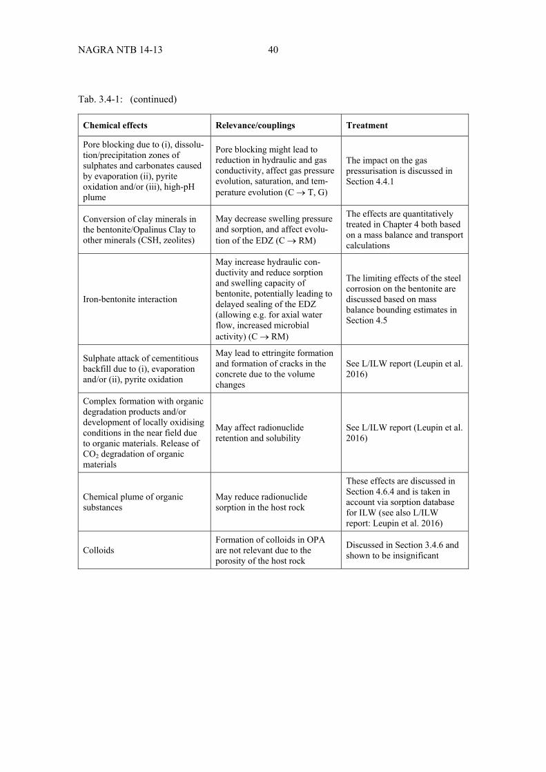
NAGRA NTB 14-13 40
Tab. 3.4-1: (continued)
Chemical effects Relevance/couplings Treatment
Pore blocking due to (i), dissolu-tion/precipitation zones of sulphates and carbonates caused by evaporation (ii), pyrite oxidation and/or (iii), high-pH plume
Pore blocking might lead to reduction in hydraulic and gas conductivity, affect gas pressure evolution, saturation, and tem-perature evolution (C T, G)
The impact on the gas pressurisation is discussed in Section 4.4.1
Conversion of clay minerals in the bentonite/Opalinus Clay to other minerals (CSH, zeolites)
May decrease swelling pressure and sorption, and affect evolu-tion of the EDZ (C RM)
The effects are quantitatively treated in Chapter 4 both based on a mass balance and transport calculations
Iron-bentonite interaction
May increase hydraulic con-ductivity and reduce sorption and swelling capacity of bentonite, potentially leading to delayed sealing of the EDZ (allowing e.g. for axial water flow, increased microbial activity) (C RM)
The limiting effects of the steel corrosion on the bentonite are discussed based on mass balance bounding estimates in Section 4.5
Sulphate attack of cementitious backfill due to (i), evaporation and/or (ii), pyrite oxidation
May lead to ettringite formation and formation of cracks in the concrete due to the volume changes
See L/ILW report (Leupin et al. 2016)
Complex formation with organic degradation products and/or development of locally oxidising conditions in the near field due to organic materials. Release of CO2 degradation of organic materials
May affect radionuclide retention and solubility
See L/ILW report (Leupin et al. 2016)
Chemical plume of organic substances
May reduce radionuclide sorption in the host rock
These effects are discussed in Section 4.6.4 and is taken in account via sorption database for ILW (see also L/ILW report: Leupin et al. 2016)
Colloids Formation of colloids in OPA are not relevant due to the porosity of the host rock
Discussed in Section 3.4.6 and shown to be insignificant

41 NAGRA NTB 14-13
4 Quantitative assessment of the repository-induced effects
4.1 Safety function indicator criteria for the assessment of processes
The purpose of this section is to formulate safety function indicator criteria for key parameters describing the site-specific evolution of the host rock in response to the processes considered. If the parameter values can be shown to meet these criteria, then potentially important detrimental effects related to the process can be excluded (see Section 1.2.2 for the methodology).
The hereby listed safety function criteria are based on the current understanding of the reposi-tory system and host-rock behaviour and might be subjected to adjustments when site specific parameters are known or progresses made that allow for a better understanding of the system evolution. The scientific robustness of the safety function criteria listed below varies but conti-nuous efforts are made to constrain uncertainties.
The scope of the safety function indicator criteria is limited to repository-induced effects on the host rock and engineered barriers (see Tab. 4.1-1). The criteria will vary to some extent according to the chosen site (which affects repository depth), as will the calculated values of the parameters. Safety function indicators relevant for the assessment of the repository safety and repository-induced effects were derived from Nagra (2008c), Appendix A.
Tab. 4.1-1: Safety function criteria for the assessment of processes.
Effects Relevant Process Safety function indicator criteria
Table
Thermal Thermal effect on the host rock Maximum rock temperature 4.1-2
Thermally induced increase of porewater pressure
Pressure maximum 4.1-3
Mechanical EDZ formation EDZ radial extent and hydraulic conductivity
4.1-4
Effect of the EDZ (and other processes in near field) on the buffer swelling pressure/density
Maximum and minimum density of the buffer
4.1-5
Vertical propagation of faults related to the formation of the EDZ
Vertical extent of the EDZ 4.1-6
Effect of the EDZ – convergence interaction Advective water flow (conver-gence-induced water flow)
4.1-7
Gas and Hydraulic
Gas pressure build-up Gas pressure (threshold for pathway dilation and gas fracking)
4.1-8
Gas-induced porewater displacement through host rock
Porewater displacement 4.1-9
Chemical Degradation of concrete emplacement room liner
Loss of safety-relevant properties of the engineered barriers
4.1-10
Iron-clay interactions Loss of safety-relevant properties of the engineered barriers
4.1-10

NAGRA NTB 14-13 42
Safety function indicator criteria for the assessment of processes related to the thermal effects on the host rock
The criterion for host rock temperature is that it should remain below the maximum paleotem-perature experienced by the host rock, i.e. the maximum temperature to which the rock has been subjected throughout its geological history (see Tab. 4.1-2 and Section 3.1.2 for further explana-tion). For example, in the context of the demonstration of the disposal feasibility for SF, HLW and ILW in Opalinus Clay at the site Zürich Nordost (ZNO), the criterion is thus that the maxi-mum temperature should be < 85° C (Nagra 2002b). If the temperature meets this criterion, significant thermally induced mineralogical alterations can be excluded.
Tab. 4.1-2: Criteria for the thermal effect on the host rock.
Issue Definition and description Reference
Relevance to safety functions
Precautionary criterion to avoid significant changes in the safety-relevant properties of the host rock
See Nagra (2002b)
Safety function indicator Temperature [° C]
Safety function indicator criterion
Maximum rock tempertaure < paleotemperature maximum (80 – 90° C)
Application of criterion The criterion applies to the part of the host rock that acts as a barrier
Justification Heating the host rock above its paleotemperature maximum engenders an inherent uncertainty regarding its chemical and mineralogical evolution (Nagra 2002b)
Elevated temperatures will cause a transient increase of pore pressure within the host rock. The pore pressures attained will also potentially be influenced by the presence of (and generation by the repository of) gas. In the case of SF and HLW, little gas is generated while the thermal out-put of the canister is still high and, in the case of ILW, the thermal output of the waste is too low to greatly increase the pressure in the rock. The safety function indicator criterion for the ther-mally induced increase of porewater pressure (Tab. 4.1-3) is set to the lithostatic pressure at repository depth16. This criterion is used in the oil and gas industry as an indicator for the assessment of the borehole stability, as discussed in more detail in Senger et al. (2013), and, if it is met, the possibility that a rock fracture will be generated and will propagate to a feature that could form a preferential release pathway (fractures, sedimentary architectural elements, faults / fault zones, and combinations of these features) can be excluded. As an additional, pre-cautionary measure, the respective distance to such features will be set, based on site- and repository-specific considerations.
16 In this generic approach lithostatic pressure is used as a rough indicator for minimum stress at repository level. It
is possible to constrain the magnitude of minimum stress when site specific information about the repository peri-meter is available.
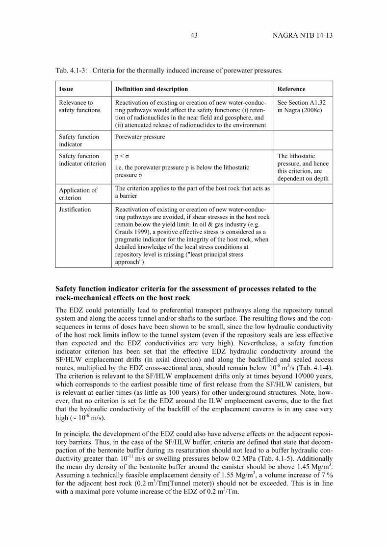
43 NAGRA NTB 14-13
Tab. 4.1-3: Criteria for the thermally induced increase of porewater pressures.
Issue Definition and description Reference
Relevance to safety functions
Reactivation of existing or creation of new water-conduc-ting pathways would affect the safety functions: (i) reten-tion of radionuclides in the near field and geosphere, and (ii) attenuated release of radionuclides to the environment
See Section A1.32 in Nagra (2008c)
Safety function indicator
Porewater pressure
Safety function indicator criterion
p < σ
i.e. the porewater pressure p is below the lithostatic pressure σ
The lithostatic pressure, and hence this criterion, are dependent on depth
Application of criterion
The criterion applies to the part of the host rock that acts as a barrier
Justification Reactivation of existing or creation of new water-conduc-ting pathways are avoided, if shear stresses in the host rock remain below the yield limit. In oil & gas industry (e.g. Grauls 1999), a positive effective stress is considered as a pragmatic indicator for the integrity of the host rock, when detailed knowledge of the local stress conditions at repository level is missing ("least principal stress approach")
Safety function indicator criteria for the assessment of processes related to the rock-mechanical effects on the host rock
The EDZ could potentially lead to preferential transport pathways along the repository tunnel system and along the access tunnel and/or shafts to the surface. The resulting flows and the con-sequences in terms of doses have been shown to be small, since the low hydraulic conductivity of the host rock limits inflow to the tunnel system (even if the repository seals are less effective than expected and the EDZ conductivities are very high). Nevertheless, a safety function indicator criterion has been set that the effective EDZ hydraulic conductivity around the SF/HLW emplacement drifts (in axial direction) and along the backfilled and sealed access routes, multiplied by the EDZ cross-sectional area, should remain below 10-8 m3/s (Tab. 4.1-4). The criterion is relevant to the SF/HLW emplacement drifts only at times beyond 10'000 years, which corresponds to the earliest possible time of first release from the SF/HLW canisters, but is relevant at earlier times (as little as 100 years) for other underground structures. Note, how-ever, that no criterion is set for the EDZ around the ILW emplacement caverns, due to the fact that the hydraulic conductivity of the backfill of the emplacement caverns is in any case very high ( 10-6 m/s).
In principle, the development of the EDZ could also have adverse effects on the adjacent reposi-tory barriers. Thus, in the case of the SF/HLW buffer, criteria are defined that state that decom-paction of the bentonite buffer during its resaturation should not lead to a buffer hydraulic con-ductivity greater than 10-11 m/s or swelling pressures below 0.2 MPa (Tab. 4.1-5). Additionally the mean dry density of the bentonite buffer around the canister should be above 1.45 Mg/m3. Assuming a technically feasible emplacement density of 1.55 Mg/m3, a volume increase of 7 % for the adjacent host rock (0.2 m3/Tm(Tunnel meter)) should not be exceeded. This is in line with a maximal pore volume increase of the EDZ of 0.2 m3/Tm.

NAGRA NTB 14-13 44
Tab. 4.1-4: Criteria for the EDZ formation.
Issue Definition and description Reference
Relevance to safety functions
The EDZ, if sufficiently large and conductive, could provide a flow and transport pathway that would by-pass the transport barrier provided by the host rock and – where present – the confining units. As a result, the safety functions: (i) retention of radionuclides in the near field and geosphere, and (ii) attenuated release of radionuclides to the environment would be affected. Brittle failure of the rock caused by the excavation process gives rise to an increase of porosity of the EDZ (nEDZ) as compared to the intact rock (nOPA ). The EDZ-induced new porespace consists of macropores, which are the preferred sites for microbial activities. Possible recompaction of the EDZ is associated with deviations of the actual buffer density and swelling pressure from the design values.
See: A1.29 in Nagra (2008c)
Safety function indicator
Product of EDZ radial cross-sectional area (AEDZ) and hydraulic conductivity (KEDZ) Product of EDZ radial cross-sectional area (AEDZ) and increase of porosity Δn = (nEDZ – nOPA)
Safety function indicator criteria
Hydraulic conductance of the EDZ KEDZ × AEDZ < 10-8 m3/s KEDZ – effective hydraulic conductivity of the EDZ AEDZ – effective cross-sectional area of the EDZ Max. acceptable void volume per m length of the SF/HLW drift (nEDZ – nOPA )× AEDZ × Fc < 0.325 m3/Tm nEDZ – effective porosity of EDZ, nOPA – porosity of intact host rock Tm – tunnel metre Fc Closure coefficient
Criterion will be dependent on repository depth if the hydraulic conductivity of the EDZ (which is related to that of the host rock) is depth depen-dent
Application of criterion
The criterion applies to the EDZ around the backfilled and sealed emplacement rooms of the main and pilot repository.
Justification Calculations reported in Poller et al. (2014) indicate that, at values of KEDZ × AEDZ of around 10-8 m3/s or above (cases SA4, SA5 and SA6), the repository tunnel system and access structures with their adjacent EDZs can provide more significant pathways contributing to peak dose rates (especially via the construction and ventilation shafts, CS and VS) compared to the host rock. It should be noted that the regulatory dose rate guideline of 0.1 mSv/a is not exceeded in the calculations reported in Poller et al. (2014) even for higher values of KEDZ × AEDZ, since the flows along the repository tunnel system and access structures remain limited by the low hydrau-lic conductivity of the host rock. Increase in void volume:
The volume around the HLW canisters to be backfilled is 4.5 m3/Tm, resulting from an initial tunnel diameter of 3 m, a thickness of the shotcrete liner of 0.2 m and a diameter of the canister of 1.05 m. The achievable bentonite emplacement density is assumed to be 1.55 Mg/m3 and the acceptable minimum density is 1.45 Mg/m3, which refers to a closure of the EDZ resulting in void volume smaller than 0.325 m3/Tm. The corresponding bentonite material density allows for fullfilling all the safety functions.

45 NAGRA NTB 14-13
Tab. 4.1-5: Criteria for the effects of the EDZ (and other processes in near field) on the buffer swelling pressure/density.
Issue Definition and description Reference
Relevance to safety functions
Enlargement of the EDZ around the SF/HLW emplacement drifts combined with other physico-chemical processes (see below) in the near field could potentially cause changes in buffer density and consequently in its swelling pressure and hydraulic conductivity that could affect its safety functions
Safety function indicator
Ps [Pa] – Swelling pressure of buffer
K [m/s] – Hydraulic conductivity of buffer
Safety function indicator criteria
0.2 MPa < Ps < minimum principal stress in the host rock around the emplacement rooms
K < 10-11 m/s for buffer around canister
Justification Ps > 0.2 MPa to avoid canister sinking (Åkesson et al. 2010)
Ps < minimum principal stress in the host rock to avoid plastic deformation of the host rock along the bedding planes.
Attenuation safety function of the buffer, by ensuring diffu-sive transport for K < 10-11 m/s (Leupin & Johnson 2013)
The EDZ, if it were sufficiently large, could in principle approach the upper or lower boundaries of the effective containment zone (host rock and confining units), reducing the extent of the undisturbed geological barrier. Calculations indicate that the geological barrier remains suffi-ciently effective provided a hydraulic conductivity of 10-12 m/s or less is maintained over a distance of at least 20 m (Nagra 2014c). Thus, the extent of the EDZ should not be such that it increases the hydraulic conductivity above this value at distances less than 20 m from the upper or lower boundaries of the host rock (Tab. 4.1-6).
Tab. 4.1-6: Criteria for the effect of the EDZ – convergence interaction.
Issue Definition and description Reference
Relevance to safety functions
The EDZ will diminish the extent of undisturbed host rock and, if sufficiently large, could hence compromise the host rock safety functions
Safety function indicator
T [m] – thickness of undisturbed host rock (with K < 10-12 m/s)
Safety function indicator criteria
T > 20 m
Justification The required minimum thickness of undisturbed Opalinus Clay is 20 m in order to comply with legal and regulatory guidelines for the dose maxima (Nagra 2008c)

NAGRA NTB 14-13 46
In the reference scenario for SF/HLW, convergence of the Opalinus Clay around the emplace-ment drift is assumed to be complete before canister breaching, and hence has no effect on radionuclide release. Furthermore, swelling of the bentonite buffer could foster the recompac-tion of the EDZ (see Geomechanica 2013), giving rise to the reduction of the effective conduc-tance of the EDZ (Alcolea et al. 2014). In the Reference Case for ILW, tunnel convergence is assumed to occur during repository construction and resaturation, with little or no deformation of the tunnel cross section occurring after resaturation of the emplacement caverns, i.e. after the start of radionuclide release. If alternative assumptions regarding the extent and duration of tunnel convergence are considered, then some enhanced water flow either through the host rock or through the access tunnel system might be possible (Nagra 2002b). A criterion on the maxi-mum magnitude of this water flow is given in Tab. 4.1-7.
Tab. 4.1-7: Criterion for gas-induced porewater displacement through host rock.
Issue Definition and description Reference
Relevance to safety functions
Excessive convergence-induced porewater displacement rates would affect the safety functions: (i) retention of radionuclides in the near field and geosphere, and (ii) attenuated release of radionuclides to the environment
See: Nagra (2002c)
Safety function indicator
Darcy flow rate [m/s]
Safety function indicator criterion
q 10-11 m/s
i.e. the Darcy flow rate, q, in the host rock due to conver-gence-induced specific porewater displacement should not exceed 10-11 m/s
Application of criterion
The criterion applies to the backfilled and sealed emplace-ment rooms of the main and pilot repository
Justification Figure A5.2-1 in (Nagra 2008c) shows that the dose rate criterion of 0.1 mSv/a can be fulfilled for all waste types if the hydraulic conductivity of the host rock K 10-10 m/s (assuming a hydraulic gradient of I = 0.1 m/m), i.e. for q = K × I 10-11 m/s
Safety function indicator criteria for the assessment of processes related to the gas pressure build-up on the host rock
Repository-generated gas will enter the rock by diffusion and, as the gas pressure increases beyond the gas entry pressure, by advection (two-phase flow) through the existing pore space in the rock. If the gas pressure increases still further, a critical pressure may be reached at which pathway dilation occurs. This process is not thought to lead to permanent damage to the favourable properties of the rock, since the microscopic dilated pathways are expected to close again once the gas pressure declines. However, if the process can be excluded, then this simpli-fies the analysis of the system and excludes some uncertainties. Thus, a safety function indicator criterion on gas pressure range for the exclusion of pathway dilation is defined in Tab. 4.1-8. At still higher pressures (if reached), the formation of macroscopic gas-induced fractures cannot be ruled out a priori. If this were to occur, irreversible changes to the favourable properties of the rock cannot be excluded. Thus, a safety function indicator criterion on gas pressure for the exclusion of gas-induced fractures is also defined in Tab. 4.1-8.
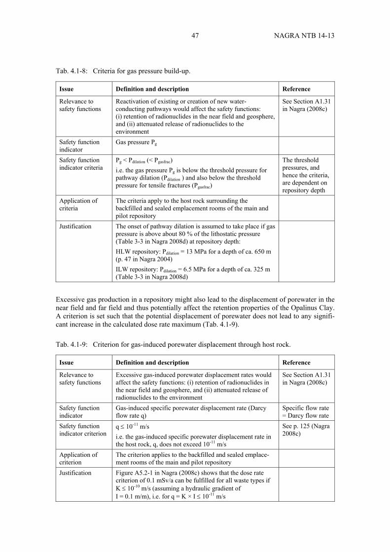
47 NAGRA NTB 14-13
Tab. 4.1-8: Criteria for gas pressure build-up.
Issue Definition and description Reference
Relevance to safety functions
Reactivation of existing or creation of new water-conducting pathways would affect the safety functions: (i) retention of radionuclides in the near field and geosphere, and (ii) attenuated release of radionuclides to the environment
See Section A1.31 in Nagra (2008c)
Safety function indicator
Gas pressure Pg
Safety function indicator criteria
Pg < Pdilation (< Pgasfrac) i.e. the gas pressure Pg is below the threshold pressure for pathway dilation (Pdilation ) and also below the threshold pressure for tensile fractures (Pgasfrac)
The threshold pressures, and hence the criteria, are dependent on repository depth
Application of criteria
The criteria apply to the host rock surrounding the backfilled and sealed emplacement rooms of the main and pilot repository
Justification The onset of pathway dilation is assumed to take place if gas pressure is above about 80 % of the lithostatic pressure (Table 3-3 in Nagra 2008d) at repository depth: HLW repository: Pdilation = 13 MPa for a depth of ca. 650 m (p. 47 in Nagra 2004) ILW repository: Pdilation = 6.5 MPa for a depth of ca. 325 m (Table 3-3 in Nagra 2008d)
Excessive gas production in a repository might also lead to the displacement of porewater in the near field and far field and thus potentially affect the retention properties of the Opalinus Clay. A criterion is set such that the potential displacement of porewater does not lead to any signifi-cant increase in the calculated dose rate maximum (Tab. 4.1-9).
Tab. 4.1-9: Criterion for gas-induced porewater displacement through host rock.
Issue Definition and description Reference
Relevance to safety functions
Excessive gas-induced porewater displacement rates would affect the safety functions: (i) retention of radionuclides in the near field and geosphere, and (ii) attenuated release of radionuclides to the environment
See Section A1.31 in Nagra (2008c)
Safety function indicator
Gas-induced specific porewater displacement rate (Darcy flow rate q)
Specific flow rate = Darcy flow rate
Safety function indicator criterion
q 10-11 m/s i.e. the gas-induced specific porewater displacement rate in the host rock, q, does not exceed 10-11 m/s
See p. 125 (Nagra 2008c)
Application of criterion
The criterion applies to the backfilled and sealed emplace-ment rooms of the main and pilot repository
Justification Figure A5.2-1 in Nagra (2008c) shows that the dose rate criterion of 0.1 mSv/a can be fulfilled for all waste types if K 10-10 m/s (assuming a hydraulic gradient of I = 0.1 m/m), i.e. for q = K × I 10-11 m/s
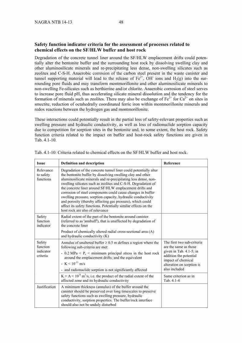
NAGRA NTB 14-13 48
Safety function indicator criteria for the assessment of processes related to chemical effects on the SF/HLW buffer and host rock
Degradation of the concrete tunnel liner around the SF/HLW emplacement drifts could poten-tially alter the bentonite buffer and the surrounding host rock by dissolving swelling clay and other aluminosilicate minerals and re-precipitating less dense, non-swelling silicates such as zeolites and C-S-H. Anaerobic corrosion of the carbon steel present in the waste canister and tunnel supporting material will lead to the release of Fe2+, OH- ions and H2(g) into the sur-rounding pore fluids and may transform montmorillonite and other aluminosilicate minerals to non-swelling Fe-silicates such as berthierine and/or chlorite. Anaerobic corrosion of steel serves to increase pore fluid pH, thus accelerating silicate mineral dissolution and the tendency for the formation of minerals such as zeolites. There may also be exchange of Fe2+ for Ca2+ on sites in smectite, reduction of octahedrally coordinated ferric iron within montmorillonite minerals and redox reactions between the hydrogen gas and montmorillonite.
These interactions could potentially result in the partial loss of safety-relevant properties such as swelling pressure and hydraulic conductivity, as well as loss of radionuclide sorption capacity due to competition for sorption sites in the bentonite and, to some extent, the host rock. Safety function criteria related to the impact on buffer and host-rock safety functions are given in Tab. 4.1-10.
Tab. 4.1-10: Criteria related to chemical effects on the SF/HLW buffer and host rock.
Issue Definition and description Reference
Relevance to safety functions
Degradation of the concrete tunnel liner could potentially alter the bentonite buffer by dissolving swelling clay and other aluminosilicate minerals and re-precipitating less dense, non-swelling silicates such as zeolites and C-S-H. Degradation of the concrete liner around SF/HLW emplacement drifts and corrosion of steel components could cause changes in buffer swelling pressure, sorption capacity, hydraulic conductivity and porosity (thereby affecting gas pressure), which could affect its safety functions. Potentially similar effects on the host rock are also of relevance
Safety function indicator
Radial extent of the part of the bentonite around canister (referred to as 'annbuff'), that is unaffected by degradation of the concrete liner Product of chemically altered radial cross-sectional area (A) and hydraulic conductivity (K)
Safety function indicator criteria
Annulus of unaltered buffer 0.5 m defines a region where the following sub-criteria are met: - 0.2 MPa < Ps < minimum principal stress in the host rock
around the emplacement drifts; and the equivalent - K < 10-11 m/s - and radionuclide sorption is not significantly affected
The first two sub-criteria are the same as those given in Tab. 4.1-5; in addition the potential impact of chemical alteration on sorption is also included
K × A < 10-8 m3/s, i.e. the product of the radial extent of the affected zone and its hydraulic conductivity
Same criterion as in Tab. 4.1-4
Justification A minimum thickness (annulus) of the buffer around the canister should be preserved over long timescales to preserve safety functions such as swelling pressure, hydraulic conductivity, sorption properties. The buffer/rock interface should also not be unduly disturbed
49 NAGRA NTB 14-13
4.2 Effects related to temperature evolution
4.2.1 Overview
The specific temperature-related issues in a SF/HLW repository comprise the impacts of reposi-tory-generated heat on (i) the host rock and the excavation damaged zone (EDZ), (ii) the bentonite buffer, (iii) the rate of waste form degradation, (iv) corrosion rates of carbon steel, (v) solubility and sorption of released radionuclides and (vi) thermally induced overpressures and their possible adverse effect on the integrity of the engineered and natural barriers17. The early-time thermal evolution of the SF/HLW near-field results in a period of elevated temperatures in the bentonite buffer and in increased pore pressures within the host rock and in the backfilled repository due to thermal expansion of the pore fluid and differential expansion of host rock pore fluid compared with the rock framework. The pore-pressure evolution of the repository will also potentially be influenced by the presence of (and generation by the repository of) gas, although, in the case of SF/HLW, little gas is generated while the thermal output of the canister is still high.
Analyses have been carried out to investigate temperature and pore-pressure evolution in the various repository configurations under consideration, covering the range of conceptual and parametric uncertainties, and to compare the results with the relevant safety function indicator criteria. The safety-relevant criterion for host-rock temperature is that it should remain below the maximum paleotemperature experienced by the host rock, i.e. the maximum temperature to which the rock has been subjected throughout its geological history (see Tab. 4.1-2). If the tem-perature meets this criterion, significant thermally induced mineralogical alteration can be excluded. Thus, the safety function indicator criteria for fluid pore pressure given in Tab. 4.1-3 are set such that, if they are met, the possibility can be excluded that a fracture will be generated and will propagate to a feature that could form a preferential release pathway (fractures, sedi-mentary architectural elements, faults / fault zones, and combinations of these features).
The temperature evolution in the L/ILW repository is dominated by the heat pulse generated by cement hydration. Calculations have shown that the temperature increase for the reference case does not exceed 5 – 10° C and that the peak is only short-lived (see Leupin et al. 2016). At this temperature, mineralogical changes occur neither in the clay rock nor in the cement matrix. As a result, no temperature effect on dose calculations is to be expected. A similar temperature evolu-tion is expected for the ILW repository.
17 The impact of heat from cement hydration in the ILW emplacement caverns is negligible (see also Darcis et al.
2014).

NAGRA NTB 14-13 50
4.2.2 Modelling approach
To investigate temperature evolution and the main controls on the pore pressure build-up in a HLW repository, a 2D model of a generic SF/HLW emplacement drift was used to simulate the combined effect of heat emission and gas migration through the intact host rock. A comprehen-sive sensitivity study was performed to evaluate in detail the development of porewater over-pressure in the EBS and the host rock for a variety of repository configurations (Senger et al. 2014). The emphasis was on the assessment of the impact of the geological and hydrogeological conditions on pressure build-up in a SF/HLW emplacement drift and near-field host rock, considering the associated conceptual and parametric uncertainties in the siting regions, namely:
the effect of the thermal and gas-related rock properties (thermal conductivity, intrinsic permeability, capillary pressure, relative permeability)
the role of thermal and hydraulic state conditions (initial and boundary conditions at reposi-tory depth)
the sensitivity to the assumed evolution of heat production.
For modelling the effect of multiphase flow and heat dissipation processes on the evolution of the SF/HLW near field, a numerical model was implemented with TOUGH2 using the equation-of-state module EOS5 for hydrogen and water (Pruess et al. 1999). The use of a TH code for the assessment of thermally induced overpressures represents a conservative approach, because the contribution of thermal stresses to the mean effective stress is not considered (increase of mean effective stress in the EDZ), but only the reduction of effective stress due to the thermally induced porewater overpressures is accounted (reduction of mean effective stress; see also Section 3.1.2). The detailed information on the modelling study is given in Senger et al. (2014) and summarised below.
4.2.3 Model implementation
The sensitivity analysis of early thermal effects due to heat generation associated with the radio-active decay of radionuclides in the SF/HLW is based on the 3D model used in Senger & Ewing (2008). The model geometry represents the generic design of the SF/HLW drifts for a deep repository setting (Nagra 2011). In order to account for the regional thermo-hydraulic con-ditions and the effect of gas generation, the 3D model geometry was simplified to a 2D cross-sectional model, which was extended by 1D elements connected to the land surface above and to the crystalline basement below (Fig. 4.2-1). Three model configurations were used, represen-ting the three repository depths at three different siting regions for a SF/HLW repository.
The hydraulic and gas-related properties of the Opalinus Clay host rock are elaborated in Senger et al. (2013) and are used as input in the numerical model assuming effective (averaged) host-rock properties. The hydraulic properties of the hydrogeological units above and below the host rock were derived from Papafotiou & Senger (2013, 2014a and b). Hydraulic property assign-ment for the units below the Muschelkalk aquifer was based on other data compilations (see also Nagra 2008d).
The initial conditions represent overall hydrostatic pressure conditions for the siting regions at the depths under consideration. The specific initial pressure distributions are based on a steady-state temperature distribution, which is in turn based on calibrated thermal conductivities from the measured temperatures in boreholes using the basal heat fluxes in the three siting regions and a prescribed temperature of 10° C at the land surface. Atmospheric pressure was prescribed at the land surface and hydrostatic pressures were computed over the entire depth profile to the crystalline basement.

51 NAGRA NTB 14-13
Fig. 4.2-1: 2D model geometry of a SF/HLW emplacement drift in the Opalinus Clay, with the 1D extention to the prescribed boundary conditions at the top (land surface) and at the bottom (crystalline).
A one-year operational period was simulated representing the effect of ventilation in an open emplacement drift. Conditions at the end of this period were used as initial conditions for the post-closure period, during which heating from radioactive decay of the waste and gas genera-tion from corrosion of the waste canister and construction material in the liner were taken into account. For the post-closure simulation, hydrostatic pressures were prescribed at the top and bottom elevation of the 2D model, accounting for possible lateral drainage of excess pressures in the overlying and underlying units surrounding the host rock (Figure 3-2 in Senger et al. 2013). No-flow conditions were specified at the lateral boundaries to mimic the effect of a pattern of parallel emplacement drifts.
Generic heat generation rates from the radioactive decay for relevant waste types from the MIRAM 2012 inventory (Nagra 2013) were represented in the model by time-varying heat pro-duction rates. Two heat production curves, representing maximum and average rates, were used in the sensitivity study, covering the range of variability for different fuel assemblies. A range of gas generation rates was provided as input to the sensitivity analyses of gas release from a SF/HLW repository (Papafotiou & Senger 2014c), including a reference value, as well as upper and lower bounding values. For the evaluation of the combined pressure build-up from heat and gas generation, the so-called reference values were used, representative of gas generation from corrosion of the waste canister (0.01 m³/Tm a for 60'000 years) and from corrosion of tunnel installations (0.06 m³/Tm a for 2'000 years).
The modelling products are simulated pressure transients, temperatures, gas saturations and the corresponding contour plots at vertical cross sections. Maximum temperatures in the host rock can be compared with the maximum paleotemperature experienced by the rock and vertical gas pressure profiles can be compared with the lithostatic pressure, these being the relevant safety function indicator criteria for effects related to temperature evolution (see Tabs. 4.1-2 and 4.1-3). In addition, the thermal and pressure-induced expansion of the entire layer column room from repository level to ground level can be estimated from the calculated temperature and pressure profiles, which can be used to derive 1D estimates of transient ground heave (see Appendix B in Senger 2014).
Effingen Member
Intrinsic permeability
Reference ¹ (600 m)
Deep ² (750 m)
Shallow ³ (450 m)
(m2) Depth (m bgl) Depth (m bgl) Depth (m bgl)
Quaternary 1E-11 0-74 - 0-89
Tertiary 1E-16 74-205 0-325 -
Malm 1E-14 205-444 325-528 89-274
1E-20 444-458 528-617
Upper confining unit 5E-20 458-545 617-695 274-395
Opalinus Clay 1E-20 545-655 695-805 395-505
Lower confining unit 5E-20 655-814 805-958 505-670
Oberer Muschelkalk 1E-14 814-877 958-1083 670-743
Unterer Muschelkalk 1E-16 877-979 1083-1130 743-848
Buntsandstein 1E-18 979-987 - 848-870
Permo-carbonif. Trough 1E-19 - 1130-2159 870-9000
Crystalline 1E-19 987-9000 2159-9000 -
¹ Corresponds to Benken lithostratigraphic profile. ² Corresponds to Weiach profile +139 m in Tertiary in order to shift tunnel depth to 750 m. ³ Corresponds to Riniken profile +64 m in Quaternary in order to shift tunnel depth to 450 m.

NAGRA NTB 14-13 52
4.2.4 Model results
The sensitivity study for thermo-hydraulic phenomena during the early post-closure period con-centrated on the temporal evolution of temperature and pore pressure in the bentonite buffer and the adjacent host rock after canister emplacement. The maximum temperature in the buffer evolved at the interface canister – bentonite during the first 10 years after canister emplacement. Depending on the simulation case the maximum temperature values ranged between 120 and 140° C. At the transition between EDZ and intact host rock the maximum temperature is reached between 100 and 500 years with peak temperatures ranging between 65 and 90° C. At a distance of 20 m from the center of the SF/HLW drift axis, the temperature in the host rock never exceeds a value of 80° C, which is below the inferred paleotemperature of the Opalinus Clay (see Section 3.1).
The evaluation of pore pressure evolution during the early post-closure period reveals that signi-ficant pore pressure build-up can develop, but that the peak pressures remain below lithostatic pressures (Fig. 4.2-2). There is little difference between the cases with average and maximum heat production rates, as the maximum heat production rate is only significantly higher than the average rate at early times; after 100 years, the two rates are similar. Thermally induced pore pressures develop in the Opalinus Clay relatively early as heat propagates radially into the sur-rounding host rock. The peak pressures are associated with the added pressurisation due to gas generation from corrosion, which is limited to the immediate vicinity of the SF/HLW emplace-ment drift. This results in a reduced pressure difference between the peak pressure in the SF/HLW drift and the elevated pore pressures in the surrounding host rock. At late times, when heat production declines and gas generation from corrosion of construction metal ceases (after 2'000 years), gas pressures in the SF/HLW drift also decline and subsequent pressure build-up associated with continued corrosion of the SF/HLW canister, which ceases after 60'000 years, is much more reduced.
The results of the simulation cases of the different repository depths indicate the greatest pressure build-up relative to the lithostatic pressures occurs assuming a repository depth of 600 m and assuming host rock properties corresponding to the deep Opalinus Clay. For a repository depth of 750 m, the pressure increase relative to the lithostatic pressure is lower, resulting in a peak pressure that is about 80 % of lithostatic. For the 450-m repository depth, the higher permeability of the shallow Opalinus Clay results in greater dissipation of excess pressure build-up and peak pressures are less than 90 % of lithostatic.
Sensitivity simulations indicate relatively little effect in terms of thermal conductivity variations or the chosen thermal pore expansivity of the Opalinus Clay. However, an increased pore com-pressibility of the host rock results in a significant reduction in the pore pressure build-up. The pore compressibility of 1.7 × 10⁻⁹ Pa-1 (corresponding to a Young-modulus of 6'000 MPa) used for all of the simulations (except for one variant).
The estimation of the potential heave of the land surface associated with the heat- and gas generation in a SF/HLW emplacement drift and corresponding temperature and pore pressure increase is based on the change in porosity of the host rock and described in detail in Senger et al. (2014). Integration of the porosity change then gives the corresponding change in elevation, assuming that the overlying and underlying units are incompressible and that the rock deforma-tion only occurs in the vertical direction. The integrated porosity change over the total thickness of the 2D model results in a total heave of about 0.2 m for the case TH01 (600-m depth, maxi-mum heat generation) and 0.25 m for TH06, which allows pressure increase beyond the 2D model boundaries (representing the maximum values of estimated heave). At 1'000 years, the estimated heave decreases compared with that after 500 years as the overall pressures and

53 NAGRA NTB 14-13
temperatures decrease (Figure 5-2 in in Senger 2014). As noted in Section 3.2.3, given the strains resulting from the thermally induced heave, it is not expected that faults would be reacti-vated by this process.
Fig. 4.2-2: Vertical pressure profiles relative to lithostatic pressures for the repository depths
considered (rows: top-600 m, middle-450 m, bottom-750 m) and for the two heat production rates (columns: left-average, right-maximum).
0
0.0 0.2TH00
0.4Fraction to Lithostatic Pressure (-)
0.6 0.8 1.0
20
-20
Z-C
oord
inat
e (m
)
-40-60
4060
10 yrs100 yrs500 yrs1000 yrs2000 yrs10 000 yrs60 000 yrs
0
0.0 0.2TH01
0.4Fraction to Lithostatic Pressure (-)
0.6 0.8 1.0
20
-20
Z-C
oord
inat
e (m
)
-40-60
4060
0
0.0 0.2TH02
0.4Fraction to Lithostatic Pressure (-)
0.6 0.8 1.0
20
-20
Z-C
oord
inat
e (m
)
-40-60
4060
0
0.0 0.2TH03
0.4Fraction to Lithostatic Pressure (-)
0.6 0.8 1.0
20
-20
Z-C
oord
inat
e (m
)
-40-60
4060
0
0.0 0.2TH04
0.4Fraction to Lithostatic Pressure (-)
0.6 0.8 1.0
20
-20
Z-C
oord
inat
e (m
)
-40-60
4060
0
0.0 0.2TH05
0.4Fraction to Lithostatic Pressure (-)
0.6 0.8 1.0
20
-20
Z-C
oord
inat
e (m
)
-40-60
4060
NAGRA NTB 14-13 54
4.2.5 Concluding remarks on the significance of thermal effects
Temperature-related issues in a SF/HLW repository and their possible adverse effects on the integrity of the engineered and natural barriers have been investigated with numerical TH models of the SF/HLW disposal system. Comparison with the relevant safety function indicator criteria indicate that thermal effects will not compromise the safety function of the barriers (engineered barriers, host rock) in any of the repository configurations under consideration. In particular, the numerical studies show that (i), thermally induced pore pressures do not exceed the lithostatic stress, which is seen as an indicator for thermal fracturing of the host rock and (ii), the host-rock temperatures remain below the maximum paleotemperature experienced by the host rock, i.e. the maximum temperature to which the rock has been subjected throughout its geological history.
4.3 Effects related to rock mechanics
4.3.1 Overview
Hydro-mechanical (HM) sensitivity analyses have been carried out to assess the extent and the shape of the EDZ around the underground structures of a HLW repository. The emphasis in the analysis is on the following components: (i) an SF/HLW emplacement drift and (ii) a vertical shaft.
Geomechanical simulations (Geomechanica 2013) provided discrete fracture networks repre-senting the EDZs around the disposal structures for a wide range of possible repository configu-rations in the Opalinus Clay. The discrete fracture networks derived from the geomechanical simulations have been used to evaluate the hydraulic significance of the EDZ (Alcolea et al. 2014). For this, a sequential modelling procedure has been developed, aimed at converting the discrete fracture networks into hydraulic continuum models with heterogeneous porosity and hydraulic-conductivity distributions. The complex shape of the EDZ has then been abstracted to provide a simplified representation that is amenable to handling with, for example, radionuclide transport modelling tools.
4.3.2 Methodology
Conceptual framework for EDZ fracture closure in Opalinus Clay
Drawing on empirical and experimental evidence about the hydraulic significance of the EDZ during tunnel construction, its evolution during operational times and after backfilling of tunnels (Lanyon et al. 2014a), the conceptual framework for a quantitative EDZ closure model can be formulated as follows (see Fig. 4.3-1):
The creation of the EDZ is a brittle process, i.e. the increase of the void volume of the plastified rock zone around the excavation is solely attributed to fracture opening, whereas the porosity of non-fractured rock domains remains essentially unchanged during the early times.
Initially, the newly created EDZ fractures are unsaturated and exposed to atmospheric pressure, whereas the non-fractured rock domains remain saturated and exhibit high matrix suction as a consequence of the high gas entry pressure of the Opalinus Clay. The initial transmissivity of the unsaturated EDZ fractures is controlled by the fracture aperture and can be very high. The matrix conductivity remains essentially unchanged, i.e. it is the same as the conductivity of the intact rock.

55 NAGRA NTB 14-13
With time, the matric suction in the rock matrix ceases due to the uptake of porewater18 from outer rock zones and the fractures start to resaturate.
Porewater uptake in the non-fractured rock zones in response to the reduction of effective stress (drained response) is associated with swelling and consequently with an increase of matrix porosity. This porosity increase of the rock matrix occurs at the expense of the fracture aperture, i.e. the fractures start to close and fracture transmissivity decreases drastically, whereas the hydraulic conductivity of the non-fractured matrix zones increases slightly as a consequence of the porosity increase.
This process of porosity and conductivity increase of the matrix is associated with a decrease of fracture aperture and transmissivity and progresses until an effective stress equi-librium is reached. This is essentially the case when the pore pressure reaches the static formation pressure.
In the following paragraphs, a heuristic EDZ model is developed that mimics the evolution des-cribed above in a simplified manner. The evolution of the hydraulic properties of the EDZ is simulated over the entire period ranging from the early post-excavation phase until static forma-tion pressure recovery.
Fig. 4.3-1: A conceptual framework for EDZ fracture closure in Opalinus Clay, covering the key phenomena and features from the early post-excavation phase until static formation pressure recovery. After Figure 2-17 of Alcolea et al. (2014). Pp: pore pressure, Patm: atmospheric pressure, Pfmt: formation pressure.
18 Note, in low permeability rock such as Opalinus Clay, vapour diffusion in the air-filled EDZ fracture network is
the dominant transport process. Assuming a relative humidity < 1 in the ventilated tunnel sections, a radial gra-dient in relative humidity is the driving force for vapour flux.
(EDZ fracture network definedby fracture orientation, density,length, aperture, ...)
EDZ fracture network
Beforeexcavation
Immediatelyafter excavation
Onset ofresaturation
Self-sealingin progress
Intact rock characterisedby matrix porosity andpermeability
Creation of tensilefractures (unsaturated)due to stress release
Resaturation of fracturesand pressure recovery
Swelling of rock matrix dueto uptake of porewater
Reference volume
liner liner
Pp = Patm Pp > Patm Pp ≈ Pfmt
NAGRA NTB 14-13 56
Modelling approach
The geomechanical simulations by Geomechanica (2013) provide discrete fracture networks representing the EDZ around the disposal structures for a wide range of repository settings representing the geological conditions in the HLW repository candidate siting regions. As an example, Fig. 4.3-2 shows the simulated fracture patterns around a SF/HLW drift at a repository depth of 750 m under different in-situ stress conditions. The plastified zone is shown consisting of tensile (blue) and shear fractures (orange). Tensile fractures, which are the more permeable hydraulic features, are located only in the immediate vicinity of the tunnel surface.
Discrete fracture networks provide input for studying the hydraulic significance of the EDZ (Alcolea et al. 2014). For this, hydraulic EDZ abstractions are derived for cylindrical tunnel cross sections in an approach consisting of the following steps (Fig. 4.3-3):
The discrete fracture networks are analysed, each of them consisting of thousands of fractures, characterised by fracture orientation, fracture length and fracture aperture. A box counting approach is applied to convert the fracture networks into cell-based porosity distributions.
An empirical porosity-permeability relationship (Kozeny-Carman) is adopted to convert cell porosities in hydraulic conductivities.
Cell-based porosity and conductivity distributions are converted to effective, uniform poro-sity / conductivity values within an annual region around the repository structure (tunnel).
Actually, the buffer zone and some fractures in the host rock are initially unsaturated. A set of two-phase flow scoping simulations has been carried out to address evolution from the initial unsaturated state. It was observed that the saturation process of the initially unsaturated pores takes 20 – 50 years. This time frame is negligible compared with the total time required for the full resaturation of the system (> 1'000 years). Therefore, the initial unsaturated state is ignored in the remaining simulations.
The resaturation process is simulated using the finite element mesh presented in Fig. 4.3-3. Boundary conditions are zero drawdown (i.e., the far field does not undergo any resaturation) at the boundaries and zero flux at the inner circle representing the canister, which is assumed impervious. Initial condition is hydrostatic pressure (which varies in depth) at elements not intersected by fractures. At elements intersected by fractures and within the buffer zone, atmo-spheric pressure conditions are imposed.
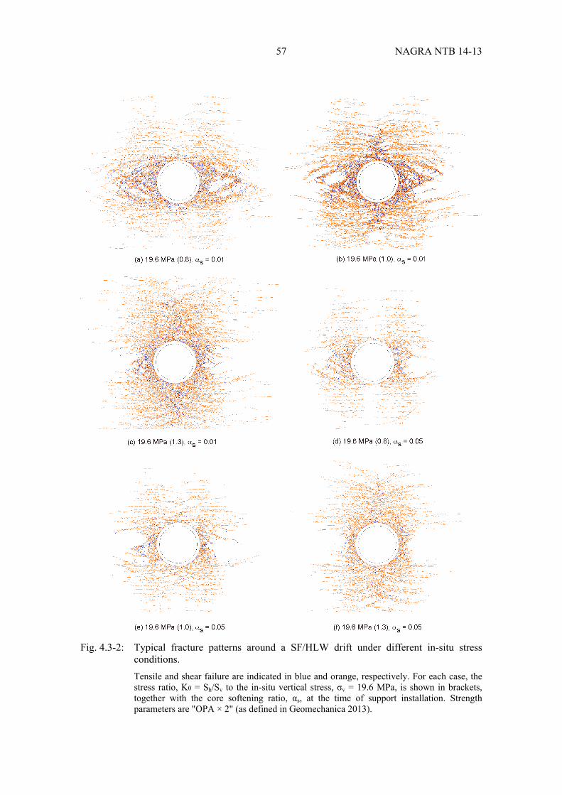
57 NAGRA NTB 14-13
Fig. 4.3-2: Typical fracture patterns around a SF/HLW drift under different in-situ stress conditions. Tensile and shear failure are indicated in blue and orange, respectively. For each case, the stress ratio, K0 = Sh/Sv to the in-situ vertical stress, σv = 19.6 MPa, is shown in brackets, together with the core softening ratio, αs, at the time of support installation. Strength parameters are "OPA × 2" (as defined in Geomechanica 2013).
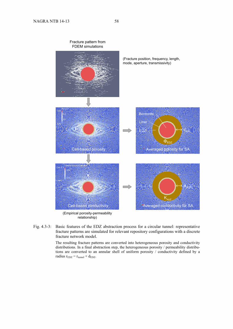
NAGRA NTB 14-13 58
Fig. 4.3-3: Basic features of the EDZ abstraction process for a circular tunnel: representative fracture patterns are simulated for relevant repository configurations with a discrete fracture network model. The resulting fracture patterns are converted into heterogeneous porosity and conductivity distributions. In a final abstraction step, the heterogeneous porosity / permeability distribu-tions are converted to an annular shell of uniform porosity / conductivity defined by a radius rEDZ = rtunnel + dEDZ.
Fracture pattern fromFDEM simulations
Cell-based porosity Averaged porosity for SA
Averaged conductivity for SACell-based conductivity
(Fracture position, frequency, length,mode, aperture, transmissivity)
(Empirical porosity-permeabilityrelationship)
dAUZ
KAUZ
dAUZ
Bentonite
Liner
EDZ
ΦEDZ
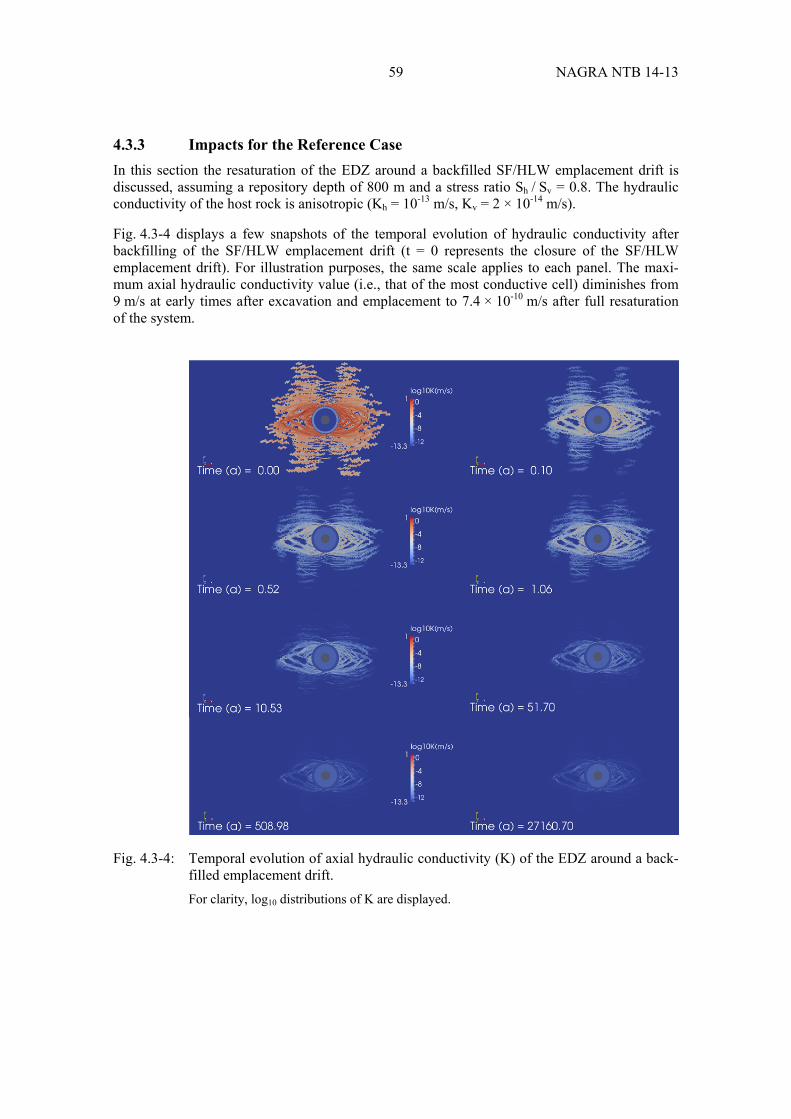
59 NAGRA NTB 14-13
4.3.3 Impacts for the Reference Case
In this section the resaturation of the EDZ around a backfilled SF/HLW emplacement drift is discussed, assuming a repository depth of 800 m and a stress ratio Sh / Sv = 0.8. The hydraulic conductivity of the host rock is anisotropic (Kh = 10-13 m/s, Kv = 2 × 10-14 m/s).
Fig. 4.3-4 displays a few snapshots of the temporal evolution of hydraulic conductivity after backfilling of the SF/HLW emplacement drift (t = 0 represents the closure of the SF/HLW emplacement drift). For illustration purposes, the same scale applies to each panel. The maxi-mum axial hydraulic conductivity value (i.e., that of the most conductive cell) diminishes from 9 m/s at early times after excavation and emplacement to 7.4 × 10⁻¹⁰ m/s after full resaturation of the system.
Fig. 4.3-4: Temporal evolution of axial hydraulic conductivity (K) of the EDZ around a back-filled emplacement drift. For clarity, log10 distributions of K are displayed.

NAGRA NTB 14-13 60
The heterogeneous distribution of hydraulic properties is then averaged by integration of the axial flux (per unit gradient) around the tunnel19. The average (equivalent) hydraulic conducti-vity is 0.039 m/s at early times and drops dramatically to values smaller than 10-12 m/s at late times, when all fractures are closed. Fig. 4.3-5 displays the temporal evolution of the equivalent EDZ hydraulic conductivity across the abstracted EDZ. The equivalent hydraulic conductivity of the EDZ drops approximately 11 orders of magnitude due to mechanical closure of fractures and swelling of the clayey materials of the matrix. The late time value of equivalent hydraulic conductivity is in good agreement with experimental values obtained at Mont Terri20 (Lanyon et al. 2014a).
The effective porosity of the EDZ can be decomposed in a fraction associated with the fractures (fracture porosity) and a contribution of the matrix (matrix porosity). Fracture porosity, matrix porosity and effective porosity can be homogenised in a similar way as described for hydraulic conductivity (see Fig. 4.3-3, upper branch). At early times, fracture porosity decreases with increasing distance from the backfilled emplacement drift (by several orders of magnitude), whereas matrix porosity is rather uniform. At late times, fracture porosity is reduced ∼4 orders of magnitude due to mechanical closure of the fractures and swelling of the clayey materials of the matrix; whereas the matrix porosity and effective porosity increase towards the tunnel walls (see Fig. 4.3-7).
Fig. 4.3-5: Temporal evolution of the equivalent hydraulic conductivity of the EDZ.
19 The enhancement of the specific flux in axial direction due to the effect of the EDZ is calculated as the arithmetic
mean of the contributions per cell. For further details see Alcolea et al. (2014). 20 In the context of the HG-A experiment, it was shown that the effective hydraulic conductivity of the EDZ around
a sealed tunnel section decreased after 5 years to values, which are 1 – 2 orders of magnitude above the conducti-vity of the intact rock.

61 NAGRA NTB 14-13
Hydraulic properties are averaged across the radial extension of the abstracted EDZ model (in this example the maximum radial extension of the EDZ at early times is 6.3 m). The average total hydraulic conductivity is 0.039 m/s at early times and drops dramatically to 2.010-13
m/s at late times, when all fractures are closed (Fig. 4.3-6). The resulting equivalent porosity21 cal-culated as the ratio void volume and effective EDZ area, which does not vary in time, is 0.15.
Fig. 4.3-6: Abstracted EDZ model, based on the reference simulation case HAA-01 FEMDEM (Table 4-1 in Geomechanica 2013). Radial distribution of equivalent hydraulic conductivity and porosity of the SF/HLW near field (including canister, bentonite buffer, liner, EDZ, host rock).
4.3.4 Impacts for variant cases
An overall evaluation of the sensitivity study consisting of a number of variant cases has been conducted addressing repository depth, stress state, rock strength, tunnel shape and design of the lining, and late time profiles (i.e., after recovery of static formation pressure) of effective poro-sity ϕEDZ (r) and effective hydraulic conductivity KEDZ(r) have been derived, as described in detail in Alcolea et al. (2014).
21 In Alcolea et al. (2014) the average value of the normalised void volume < VEDZ > (i.e. void volume per m Tunnel
length) of the EDZ is calculated by integration:
or
matrixEDZedz drrrV ))((
were ro represents the radius of the unlined tunnel. Eventually, the average void volume < VEDZ > is used to define homogenised properties of the abstracted EDZ in terms of a relationship between the equivalent porosity ϕEDZ,equiv and the associated equivalent EDZ radius requiv:
)( 20
2, rr
V
equiv
edzmatrixequivEDZ
The homogenised EDZ properties are reported in Fig. 4.3-8 for the SF/HLW drift.

NAGRA NTB 14-13 62
The evaluation of the calculated profiles show only moderate variability between cases (Fig. 4.3-7), even though the extent and shape of the EDZ fracture patterns differ considerably (Geomechanica 2013). In the case of a SF/HLW emplacement drift, close to the tunnel wall, the effective porosities range from 0.14 and 0.22. The sensitivity analyses reveal the following general dependencies of the normalised EDZ void volume VEDZ (i.e. ΔΦEDZ × AEDZ):
a distinct increase of VEDZ with increasing depth (i.e. increasing mean stress)
a distinct increase of VEDZ with decreasing rock strength
a distinct decrease of VEDZ with increasing stiffness of the tunnel support
An average value of around 0.65 m3/Tm for the normalised void volume has been derived from the analysis of a total of 25 sensitivity runs22 (Fig. 4.3-8a). The corresponding effective hydrau-lic conductivities are higher by 0.5 to 1 order of magnitude with respect to the intact rock matrix (Fig. 4.3-8b). At a distance of 2 tunnel radii (about 6 m), the rock properties are indistinguish-able from the intact rock matrix in all cases. The average hydraulic conductance KEDZ × AEDZ is in the order of 10-12 m3/s Tm.
Average profiles of ϕEDZ(r) (arithmetic mean) and KEDZ(r) (geometric mean) have also been derived from the effective porosity and conductivity profiles (Alcolea et al. 2014). The sensiti-vity studies exhibit results which are very consistent with the ones for the SF/HLW drift cross section (see Fig. 4.3-7). The moderate spread of the individual profiles around the average pro-files suggests that the average profiles can be regarded as representative ensemble means. The averaged profiles have been used to derive representative EDZ properties (equivalent porosity ϕEDZ,equiv. and hydraulic conductivity KEDZ,equiv.) as a function of equivalent radius as a basis for the annular model of the EDZ, as shown in the case of the SF/HLW emplacement drift in Fig. 4.3-8. The equivalent profiles for the vertical shaft are shown in Fig. 4.3-9.
22 According to Alcolea et al. (2014) less than 50 % of the EDZ void volume can effectively be reduced by
recompaction. The average EDZ void volume value of 0.65 m3/Tm can thus be reduced to an EDZ void volume maximum of 0.325 m3/Tm. The closure of the EDZ void volume however results in a buffer material density loss. Based on these considerations a bounding case was calculated to close 50 % of the EDZ void volume: bentonite would need to be emplaced with a dry density of ca. 1.55 Mg/m3 to end with a final material density of ca. 1.45 Mg/m3 in order to fulfill all the safety-related requirements. The sensitivity study by Alcolea et al. (2014) was aimed at investigating the impact of repository depth, in-situ stress and rock strength on the EDZ evolution. The analysis revealed that geological settings combining great repository depth and low rock strength are less favorable with respect to the safety function criterion associated with the normalised void volume.
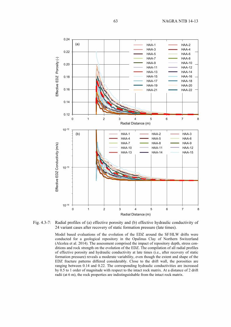
63 NAGRA NTB 14-13
Fig. 4.3-7: Radial profiles of (a) effective porosity and (b) effective hydraulic conductivity of 24 variant cases after recovery of static formation pressure (late times). Model based evaluations of the evolution of the EDZ around the SF/HLW drifts were conducted for a geological repository in the Opalinus Clay of Northern Switzerland (Alcolea et al. 2014). The assessment comprised the impact of repository depth, stress con-ditions and rock strength on the evolution of the EDZ. The compilation of all radial profiles of effective porosity and hydraulic conductivity at late times (i.e., after recovery of static formation pressure) reveals a moderate variability, even though the extent and shape of the EDZ fracture patterns differed considerably. Close to the drift wall, the porosities are ranging between 0.14 and 0.22. The corresponding hydraulic conductivities are increased by 0.5 to 1 order of magnitude with respect to the intact rock matrix. At a distance of 2 drift radii (at 6 m), the rock properties are indistinguishable from the intact rock matrix.
0.12
0.14
0.16
0.18
0.20
0.22
0.24
0 1 2 3 4 5 6 7 8
Effe
ctiv
e E
DZ
Por
osity
(-)
Radial Distance (m)
HAA-1 HAA-2HAA-3 HAA-4HAA-5 HAA-6HAA-7 HAA-8HAA-9 HAA-10HAA-11 HAA-12HAA-13 HAA-14HAA-15 HAA-16HAA-17 HAA-18HAA-19 HAA-20HAA-21 HAA-22
10-12
10-13
10-14
0 1 2 3 4 5 6 7 8
Effe
ctiv
e E
DZ
Con
duct
ivity
(m/s
)
Radial Distance (m)
HAA-1 HAA-2 HAA-3HAA-4 HAA-5 HAA-6HAA-7 HAA-8 HAA-9HAA-10 HAA-11 HAA-12HAA-13 HAA-14 HAA-15
(a)
(b)
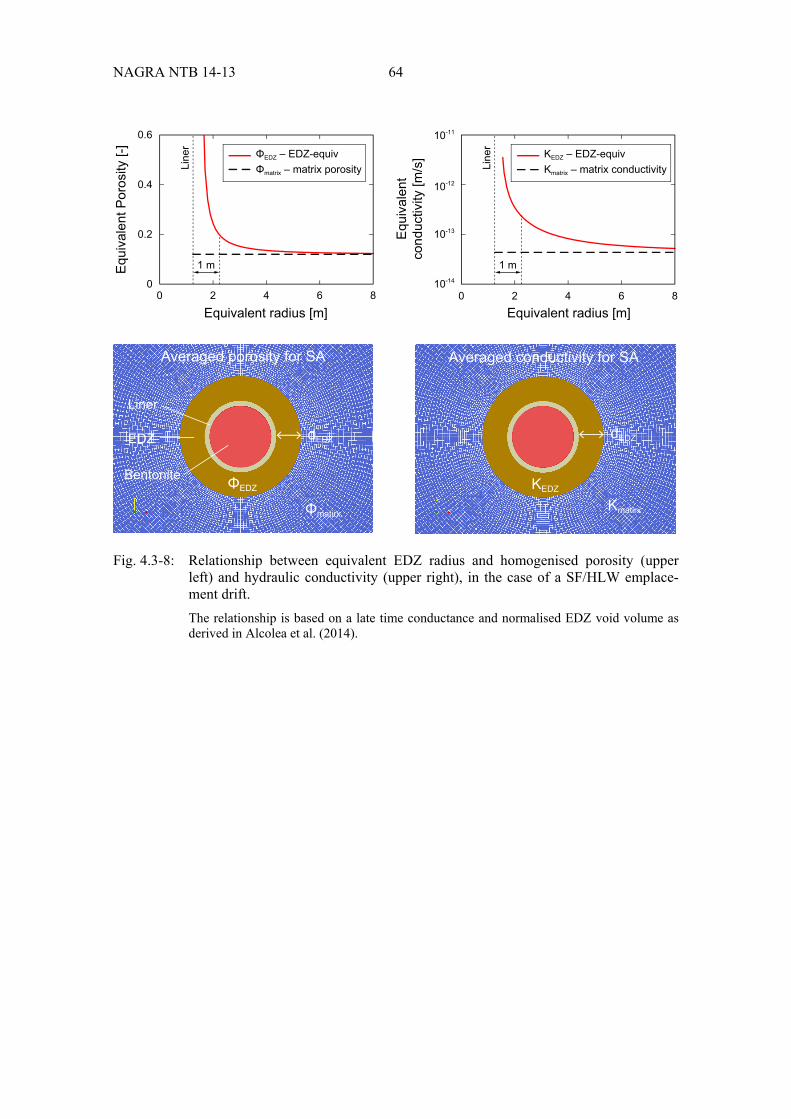
NAGRA NTB 14-13 64
Fig. 4.3-8: Relationship between equivalent EDZ radius and homogenised porosity (upper left) and hydraulic conductivity (upper right), in the case of a SF/HLW emplace-ment drift. The relationship is based on a late time conductance and normalised EDZ void volume as derived in Alcolea et al. (2014).
0
0.2
0.4
0.6
0 2
1 m
Line
r
Line
r
4 6 8
Equ
ival
ent P
oros
ity [-
]
Equ
ival
ent
cond
uctiv
ity [m
/s]
Equivalent radius [m]
ΦEDZ – EDZ-equivΦmatrix – matrix porosity
KEDZ – EDZ-equivKmatrix – matrix conductivity
10-11
10-13
10-14
0 2 4 6 8
1 m
10-12
Equivalent radius [m]
Averaged conductivity for SA
dEDZ
KEDZ
Kmatirx
Averaged porosity for SA
dEDZ
Bentonite
Liner
EDZ
ΦEDZ
Φmatirx

65 NAGRA NTB 14-13
Fig. 4.3-9: Relationship between equivalent EDZ radius and homogenised porosity (upper left) and hydraulic conductivity (upper right), in the case of a vertical shaft. The relationship is based on a late time conductance and normalised EDZ void volume as derived in Alcolea et al. (2014).
4.3.5 Concluding remarks on the hydraulic significance of the EDZ
Evaluations of the extent and hydraulic properties of the EDZ were conducted for a wide range of repository settings, covering sensitivity analyses with regard to repository depth, stress state, rock strength, tunnel shape and design of the lining. The overall assessment of the simulations indicates a marked change in hydraulic conductance of the EDZ after repository closure, which is controlled by the evolution of pore pressure in the vicinity of the backfilled underground structures. During the early times, between 10 and 100 years, the EDZ conductance is domina-ted by the high transmissivity of the fractures. As the pore pressure recovers, the EDZ fractures close progressively and the non-fractured rock matrix swells by water uptake, leading to an increase of porosity and decrease of hydraulic conductivity. After around 1'000 years, it is to be expected that most EDZ fractures are tight and the hydraulic conductance is dominated by the rock matrix. The late time conductance, normalised pore volume and radial extent of the EDZ satisfy the safety function indicator criteria for which are given in Tabs. 4.1-4 and 4.1-6.
At late times, the hydraulic conductance of the EDZ decreases by many orders of magnitude compared with its early-time values. When comparing the different simulation cases, the varia-bility of specific flux (Fig. 4.3-7) is very modest with a spread of less than an order of magni-tude. Furthermore, the radial extent of the EDZ at late times is very similar for all cases, ranging between 2 and 6 m for the HAA models.
0
0.2
0.4
0.6
0 4 8 12 16
Equ
ival
ent P
oros
ity [-
]
Equ
ival
ent
cond
uctiv
ity [m
/s]
Equivalent radius [m]
ΦEDZ – EDZ-equivΦmatrix – matrix porosity
KEDZ – EDZ-equivKmatrix – matrix conductivity
10-11
10-13
10-14
0 4 8 12 16
10-12
Equivalent radius [m]
Averaged conductivity for SA
Kmatirx
Averaged porosity for SA
Bentonite
EDZ
Φmatirx
dEDZdEDZ
1 m 1 m
ΦEDZ KEDZ

NAGRA NTB 14-13 66
The key conclusions can be summarised as follows:
At late times (i.e. after recovery of the static formation pressure) the EDZ around the back-filled underground structures of a deep geological repository in the Opalinus Clay is restricted to a radial zone with a thickness of less than 2 diameters (note that this criterion is even met at early times). Hence, the safety function criteria in Tab. 4.1-6 (vertical extent of EDZ) are met at all times.
Significant enhancement of the hydraulic conductivity is observed only in a zone with a thickness of less than half of a tunnel diameter. As late times (corresponding to the resatura-tion time of the repository), the corresponding enhancement of effective hydraulic con-ductivity in this zone is less than 1 order of magnitude with respect to the intact rock matrix. The effective hydraulic conductance is approximately 10-12 m3/s Tm and thus several orders of magnitude lower than the corresponding safety function criteria (Tab. 4.1-4).
The increase of the EDZ porosity is less than 50 % of the porosity of the intact rock matrix. An average value of around 0.65 m3/Tm for the normalised void volume has been calcu-lated, meaning that the corresponding safety function criteria (Tab. 4.1-4) can be met. For the great repository depth and for the low rock strength (e.g. strong tectonic overprint of the rocks), significant efforts may be needed with regard to the design of the tunnel support to ensure that the corresponding safety criteria are satisfied.
4.4 Effects related to gas pressure build-up and transport
4.4.1 Overview
Anaerobic corrosion of the SF/HLW canisters and other metallic components in a HLW reposi-tory (tunnel installations, including tunnel lining, steel mesh, rock anchors, tracks etc.) is associated with the formation of gas. Since the production rate of gas is higher than can be removed by dissolution and diffusion, a free gas phase will form. Fig. 4.4-1 shows a schematic representation of potential gas paths for a SF/HLW emplacement drift.
Fig. 4.4-1: Potential migration paths for corrosion gases accumulated in the SF/HLW emplacement drifts (after Nagra 2004). (1) Gas migration through EDZ, (3a/c) gas migration through the pore space and existing microfractures, (3b) gas migration through existing fractures.

67 NAGRA NTB 14-13
As canister corrosion progresses, the pressure of gas at the canister/buffer interface will increase until a critical value (the entry pressure) is reached, whereupon transport pathways will form through the saturated buffer and gas will migrate away from the canister surface to the interface with the host rock, where it will mix with gas generated by the corrosion of other metallic com-ponents.
A cementitious liner will be installed along the SF/HLW emplacement drifts at the interface between the buffer and the host rock. Chemical interaction between the liner and the adjacent buffer and rock may lead to pore clogging, increasing the resistance to the outward migration of gas, as discussed in detail in Section 3.4. It is unlikely that pore clogging will be spatially con-tinuous along the emplacement drifts, and the liner itself is likely to become fractured over time, allowing gas to migrate directly to the interface with the host rock. On the other hand, even if gas migration is prevented where the liner is present, the liner will be periodically interrupted at positions where intermediate seals of compacted bentonite are installed. In such a case, gas would migrate through the buffer to the intermediate seals, before again reaching the interface with the host rock.
Gas that is generated at, or migrates to, the interface with the host rock will accumulate there, increasing in pressure until new pathways are established that allow it to migrate further. Gas pressure at this interface is a safety function indicator. In argillaceous media such as the Opalinus Clay, sufficiently high gas pressures can create localised deformation and changes in pore volume, namely by re-opening of pre-existing, tight fractures or by the creation of new pathways (pathway dilation). This can produce preferential pathways for the generated gas, limiting any further increase in gas pressure.
Pathway dilation within the undisturbed rock may occur if gas pressure reaches about 80 % of the lithostatic formation pressure at the repository level; this is a criterion for the gas pressure safety function indicator (see Tab. 4.1-8)23. An important feature of the deformation behaviour of argillaceous rocks is their self-sealing capacity (e.g. Nagra 2002b). Permeability enhance-ment due to pathway dilation at elevated gas pressures tends not to be permanent; when the gas pressure is reduced the material reconsolidates and the hydraulic and mechanical properties of the porous medium approach the values that are characteristic of the undisturbed stress state.
If, in spite of pathway dilation, gas pressure rises to such an extent that lithostatic pressure is exceeded, then larger scale gas fracturing may occur (lithostatic pressure is a further criterion for the gas pressure safety function indicator; see Tab. 4.1-8).
The most likely situation is that gas reaching the interface with the host rock will migrate along the EDZ of the emplacement drifts and repository tunnel system, finally dissolving and diffu-sing into the rock. This is because the entry pressure for the EDZ is expected to be significantly lower than that of the undisturbed rock (Papafotiou & Senger 2014c and Nagra 2008d). The 23 Benson et al. (2002) reviewed the safety results of underground storage in the United States as part of a com-
prehensive study considering CO2 storage in deep geological formations. The authors emphasise the importance of vertical pressure gradients as an indicator for the onset of dilatancy-controlled leakage through the caprocks which cover natural gas storage formations. According to Ibrahim et al. (1970) the critical pressure gradient for dilatancy-controlled gas leakage is bracketed by the hydrostatic gradient (≈ 9.8 kPa/m) and the lithostatic gradient (≈ 22.6 kPa/m assuming a bulk density of the overburden of about 2.3 g/cm3), where the lithostatic pressure gradient represents a lower limit for the initiation of macroscopic fractures. It is noteworthy that the CSA Standard Z341 (CSA 2006) includes a recommendation that the maximum operating pressure of natural gas storage systems should not exceed 80 % of the fracture pressure of the caprock formation in order to minimise the leakage rates. In the absence of local fracture pressure data, a fracture gradient of 18.1 kPa/m is assumed, which leads to the maximum pressure gradient of 14.5 kPa/m (i.e. 80 % of the fracture gradient). Further references with a collection of case studies on critical pressure gradients in the field of reservoir engineering are found in Evans (2008).

NAGRA NTB 14-13 68
formation of pathways through the EDZ would greatly limit gas pressure build-up at the inter-face. However, in order to make a conservative estimate of the gas pressures that could poten-tially be reached, a modelling study has been carried out in which transport along the EDZ is omitted. The calculated pressures are then compared with the pressures required for pathway dilation and for larger scale gas fracturing (80 % and 100 % of the lithostatic formation pressure, respectively). The methodology and results are presented in detail in Papafotiou & Senger (2014c).
After closure of the repository, the evolution of gas pressure will be affected by numerous factors related to geology (hydrogeological and hydromechanical conditions, formation depth, hydraulic properties, confining formations) as well as aspects of the repository design (gas generation rates, properties of backfill materials, seals and EDZ, potential hydrogen consump-tion by biogenetic processes in the backfilled underground structures). Thus, a range of calcula-tion cases have been evaluated to explore the sensitivities to relevant parameter values.
It should be noted that measures can be taken if needed to reduce the gas production rate (e.g. choice of alternative canister materials, reduction in the use of materials that corrode and gene-rate gas in tunnel installations; see Chapter 5).
4.4.2 Methodology
Modelling approach and general assumptions
A 2D model of a generic SF/HLW emplacement drift (Fig. 4.4-2) has been used to simulate gas release through the surrounding Opalinus Clay host rock, with the 2D model plane perpendi-cular to the main axis of the drift. Complementary 2D simulations of the near field of a SF/HLW emplacement drift, summarised in Section 4.2, consider the early-time thermal period associated with heat generation from radioactive decay and resulting pore-pressure build-up in the repository and surrounding host rock combined with pressure build-up due to gas generation from corrosion of the waste canister and metal construction material. The results reveal that the thermally induced pore pressures develop in the Opalinus Clay relatively early as temperatures propagate radially into the surrounding host rock, whereas the gas-induced overpressuring is limited to the immediate vicinity of the SF/HLW emplacement drift. At late times after heat production has declined, pore pressures in the host rock decline and subsequent gas pressure build-up associated with continued corrosion of the SF/HLW is much lower than the pore pressures reached at early times.
To check whether the release of the accumulated gases occurs at moderate pressure so that the function of engineered and natural barriers is not impaired by excessive stresses, a comprehensive sensitivity study has been performed to evaluate in detail the gas transport capacity of the host rock for a variety of repository configurations, described in detail in Papafotiou & Senger (2014c), and summarised in the following.
The model has been implemented using the TOUGH2 equation-of-state module EOS5 for water and hydrogen (Pruess et al. 1999). The waste canisters, bentonite buffer, bentonite blocks, and tunnel installations are not represented explicitly, but are replaced by a single effective backfill material assigned to the tunnels. There is also no hydraulic connection between the tunnels other than through the host rock, and volumes of backfill in the access tunnels that are available for gas storage are not taken into account. This provides a conservative approach with respect to gas accumulation in the emplacement drifts and the associated pressure build-up. Although iso-thermal conditions are assumed, fluid properties depend on temperature, which in any given run

69 NAGRA NTB 14-13
is set equal to the ambient temperature at the assumed repository depth. Dissolution of gas in the porewater is taken into account. For computation reasons diffusive transport of dissolved gas is neglected, providing a conservative approach with respect to gas pressure build-up.
Fig. 4.4-2: Implementation of SF/HLW emplacement drifts in the 2D rectangular grid for modelling the release of waste-generated gas in Opalinus Clay.
The rock mass is assumed to behave as an elastic medium. The propagation of the gas phase through the porous medium is controlled by the gas entry pressure, also known as the capillary threshold pressure, which represents the difference between gas pressure and water pressure needed to displace the porewater from the initially fully saturated medium. Once the gas entry pressure has been exceeded, the gas mobility is controlled mostly by the intrinsic permeability of the formation, the permeability – saturation relationship (commonly known as relative per-meability), and the relationship between the capillary pressure and the water saturation (also known as suction or water retention curve). The functional dependency between the pore space saturation and the relative permeability or the capillary pressure is commonly described with parametric models, such as that by van Genuchten (1980). In calculations where the process of pathway dilation is considered, this is implemented by an approach that involves the use of a pressure-dependent multiplier (Senger et al. 2008). As noted above, the onset of pathway dila-tion is assumed to occur once gas pressure reaches 80 % of the lithostatic formation pressure at the repository level. Further details on the modelling approach are found in Senger & Papafotiou (in prep.).

NAGRA NTB 14-13 70
Geoscientific database
The results of the recent laboratory and field studies that provide the database for the gas calcu-lations are compiled and evaluated in Senger et al. (2013). The interpretation and synthesis performed for the Opalinus Clay indicate that:
The intact rock matrix of the Opalinus Clay is characterised by a very low hydraulic con-ductivity, typically in the range between 10-14 and 10-13 m/s.
Variability of rock matrix conductivity is low.
Discrete water-conducting features (WCF) or faults in the Opalinus Clay are not hydrauli-cally active.
For this study, gas-related properties have been estimated based on an effective (averaged) medium in view of the marked homogeneity of the Opalinus Clay host rock. The compilation of effective hydraulic properties for gas transport comprises four different sets of values, i.e. reference and alternative values for both shallow (300 – 500 m bgl) and deep (500 – 900 m bgl) repository configurations. Key parameters selected from these four sets in the calculation cases are the hydraulic conductivity and parameters that define the capillary pressure/saturation relationship and the relative permeability/saturation relationship.
Gas generation rates
Although corrosion of the SF/HLW canisters is the main source of repository-generated gas, the contribution of gas generated from the corrosion of tunnel installations is not negligible. Thus, separate rates of gas generation have been investigated for these two sources.
Gas generation rates due to canister corrosion are assigned:
a "realistic", reference value of 0.01 m³ of gas SATP per metre of emplacement drift per year, maintained over 60'000 years (equivalent to a corrosion rate of 2 µm per year (Diomidis 2014), and
an upper "bounding value" of 0.1 m³ of gas SATP per metre of emplacement drift per year, maintained over 10'000 years
The gas generation rate due to the corrosion of tunnel installations is assigned a "realistic", reference value of 0.06 m³ gas SATP per metre of emplacement drift per year, maintained over 2'000 years24.
24 The "realistic" gas generation rates are calculated based on a corrosion rate of 2 µm per year. The "bounding
value" is equivalent to a corrosion rate of 20 µm per year which corresponds to corrosion under wet and aerated conditions.

71 NAGRA NTB 14-13
4.4.3 Model results
In a series of sensitivity simulations, the gas transport capacity of the Opalinus Clay was evaluated for a variety of repository system properties for the different siting regions, which included:
the gas-related rock properties, comprising the reference parameter sets for "shallow" Opalinus Clay (300 – 500 m bgl) and "deep" Opalinus Clay (500 – 900 m bgl) according to Table 2-3 in Senger et al. (2013), as well as the effects of heterogeneity and pathway dilation
three different repository levels: 450 m, 600 m and 750 m bgl
the gas production rates, representing the reference values and the upper bounding rate for canister corrosion
The role of the gas-related rock properties
Simulations of gas pressure build-up were conducted for a base case and 4 different sets of gas-related rock properties, assuming a repository depth of 600 m bgl. The lithostatic pressure and the corresponding threshold pressure for the onset of pathway dilation (11.9 MPa, or 80 % of lithostatic pressure) are indicated in Fig. 4.4-3, showing the results in terms of simulated gas pressures in the emplacement drift as a function of time.
Fig. 4.4-3: Time history of gas pressure in the emplacement drift compared to 80 % of litho-static pressure (onset of pathway dilation, dashed horizontal line) for depths of 600 m bgl. Base case and sensitivity runs with spatial variability of parameter distributions (HAA01, HAA04), reduced gas transport properties (HAA02) and conservative gas generation rates (HAA03, marked with dashed line).
In addition to the base case using the reference values (RV) of gas generation rates and hydrau-lic properties, two simulations were performed with heterogeneous properties, assuming a spatially correlated property distribution (HAA01) and a spatially uncorrelated distribution (HAA04). HAA02 assumed the alternative value (AV) for the capillary strength parameter and HAA03 accounted for a conservative gas generation rate.
14
16
12
10
8
6
4
2
0102 103 104 105101100
Pre
ssur
e [M
Pa]
Time [years]
reference

NAGRA NTB 14-13 72
The results indicate that only HAA03 with conservative gas generation rates exceeds the pressure level for the onset of pathway dilation (i.e., the simulation did not include pathway dilation as a modelled process). For the reference gas generation rates, the peak pressure occurs after 2'000 years, when the corrosion of the tunnel installations ceases. The continued corrosion of the canisters leads to a second pressure peak after 60'000 years, which is slightly lower than the first one. It can be concluded that, for the reference rates, the gas transport capacity of the Opalinus Clay without invoking gas transport by pathway dilation is sufficiently high that gas is released through the host rock at acceptable excess pressures of 2 – 5 MPa above hydrostatic pressures at 600 m bgl.
The role of repository depth
The results of simulations for the different depths of 450 and 750 m bgl are summarised in Fig. 4.4-4 using parameter variants of gas-related rock properties. The corresponding threshold pressures for the onset of pathway dilation at 450 m and 750 m bgl are 8.8 and 14.8 MPa, res-pectively and the corresponding hydrostatic pressure levels are at around 4.5 and 7.5 MPa, respectively. The simulations HAA05 (750 m) and HAA09 (450 m) assume reference rock pro-perties (RV properties) and reference gas generation rates. In simulation HAA10, assuming a lower host-rock permeability for the shallow repository depth, and in the case with the upper bound of the gas generation rate (HAA11), the simulated pressures reach or exceed lithostatic pressures. However, accounting for pathway dilation, the corresponding simulation for the shallow repository depth (HAA12) shows a significant decrease of peak pressures by 30 %. For the deep repository depth, only the upper bound gas generation rate leads to a substantial increase of the peak pressure (HAA07). Similarly, the case with pathway dilation (HAA08) indicates a significant decrease of peak pressures. The results indicate that, for the reference gas generation rates, the gas transport capacity of the Opalinus Clay is sufficiently high without invoking pathway dilation to release the gas through the host rock at acceptable overpressures in the order of 2 – 5 MPa. The onset of pathway dilation is reached only in cases combining con-servative gas generation rates with low-permeability host rock, as further described below.
Fig. 4.4-4: Time history of gas pressure in the emplacement drift compared to 80 % of litho-static pressure (onset of pathway dilation, dashed horizontal lines) for repository depths of 450 (left) and 750 m bgl (right), respectively. Sensitivity runs with reduced gas transport properties (HAA06, HAA07, HAA10, HAA11) and conservative gas generation rates (HAA07, HAA08, HAA11, HAA12 marked with dashed lines). The simulations HAA05 (750 m) and HAA09 (450 m) represent the refe-rence cases (RV properties) and reference gas generation rates.
18
16
14
12
10
8
6
4
2
0102 103 104 105101
Pre
ssur
e [M
Pa]
Time [years]
20
18
16
14
12
10
8
6
4
2102 103 104 105101100100
Time [years]
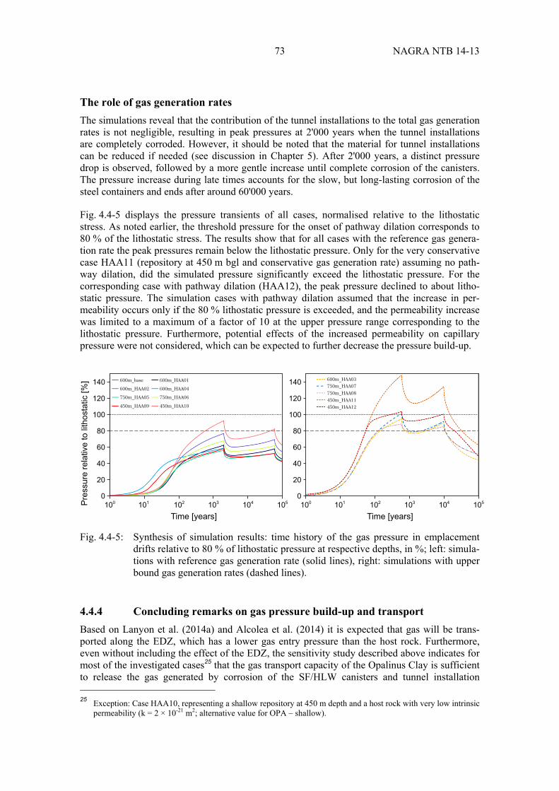
73 NAGRA NTB 14-13
The role of gas generation rates
The simulations reveal that the contribution of the tunnel installations to the total gas generation rates is not negligible, resulting in peak pressures at 2'000 years when the tunnel installations are completely corroded. However, it should be noted that the material for tunnel installations can be reduced if needed (see discussion in Chapter 5). After 2'000 years, a distinct pressure drop is observed, followed by a more gentle increase until complete corrosion of the canisters. The pressure increase during late times accounts for the slow, but long-lasting corrosion of the steel containers and ends after around 60'000 years.
Fig. 4.4-5 displays the pressure transients of all cases, normalised relative to the lithostatic stress. As noted earlier, the threshold pressure for the onset of pathway dilation corresponds to 80 % of the lithostatic stress. The results show that for all cases with the reference gas genera-tion rate the peak pressures remain below the lithostatic pressure. Only for the very conservative case HAA11 (repository at 450 m bgl and conservative gas generation rate) assuming no path-way dilation, did the simulated pressure significantly exceed the lithostatic pressure. For the corresponding case with pathway dilation (HAA12), the peak pressure declined to about litho-static pressure. The simulation cases with pathway dilation assumed that the increase in per-meability occurs only if the 80 % lithostatic pressure is exceeded, and the permeability increase was limited to a maximum of a factor of 10 at the upper pressure range corresponding to the lithostatic pressure. Furthermore, potential effects of the increased permeability on capillary pressure were not considered, which can be expected to further decrease the pressure build-up.
Fig. 4.4-5: Synthesis of simulation results: time history of the gas pressure in emplacement drifts relative to 80 % of lithostatic pressure at respective depths, in %; left: simula-tions with reference gas generation rate (solid lines), right: simulations with upper bound gas generation rates (dashed lines).
4.4.4 Concluding remarks on gas pressure build-up and transport
Based on Lanyon et al. (2014a) and Alcolea et al. (2014) it is expected that gas will be trans-ported along the EDZ, which has a lower gas entry pressure than the host rock. Furthermore, even without including the effect of the EDZ, the sensitivity study described above indicates for most of the investigated cases25 that the gas transport capacity of the Opalinus Clay is sufficient to release the gas generated by corrosion of the SF/HLW canisters and tunnel installation 25 Exception: Case HAA10, representing a shallow repository at 450 m depth and a host rock with very low intrinsic
permeability (k = 2 × 10-21 m2; alternative value for OPA – shallow).
140
120
100
80
60
40
20
0102 103 104 105101100 100P
ress
ure
rela
tive
to li
thos
tatic
[%]
Time [years]
140
120
100
80
60
40
20
0102 103 104 105101
Time [years]
600m_base
600m_HAA02
450m_HAA09
750m_HAA05
600m_HAA01
600m_HAA04
450m_HAA10
750m_HAA06
600m_HAA03
450m_HAA12450m_HAA11
750m_HAA08
750m_HAA07
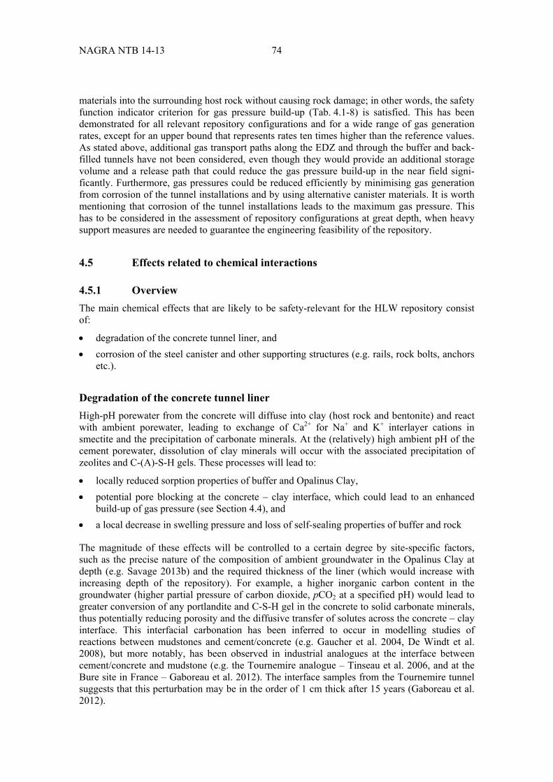
NAGRA NTB 14-13 74
materials into the surrounding host rock without causing rock damage; in other words, the safety function indicator criterion for gas pressure build-up (Tab. 4.1-8) is satisfied. This has been demonstrated for all relevant repository configurations and for a wide range of gas generation rates, except for an upper bound that represents rates ten times higher than the reference values. As stated above, additional gas transport paths along the EDZ and through the buffer and back-filled tunnels have not been considered, even though they would provide an additional storage volume and a release path that could reduce the gas pressure build-up in the near field signi-ficantly. Furthermore, gas pressures could be reduced efficiently by minimising gas generation from corrosion of the tunnel installations and by using alternative canister materials. It is worth mentioning that corrosion of the tunnel installations leads to the maximum gas pressure. This has to be considered in the assessment of repository configurations at great depth, when heavy support measures are needed to guarantee the engineering feasibility of the repository.
4.5 Effects related to chemical interactions
4.5.1 Overview
The main chemical effects that are likely to be safety-relevant for the HLW repository consist of:
degradation of the concrete tunnel liner, and corrosion of the steel canister and other supporting structures (e.g. rails, rock bolts, anchors
etc.).
Degradation of the concrete tunnel liner
High-pH porewater from the concrete will diffuse into clay (host rock and bentonite) and react with ambient porewater, leading to exchange of Ca2+ for Na+ and K+ interlayer cations in smectite and the precipitation of carbonate minerals. At the (relatively) high ambient pH of the cement porewater, dissolution of clay minerals will occur with the associated precipitation of zeolites and C-(A)-S-H gels. These processes will lead to:
locally reduced sorption properties of buffer and Opalinus Clay, potential pore blocking at the concrete – clay interface, which could lead to an enhanced
build-up of gas pressure (see Section 4.4), and a local decrease in swelling pressure and loss of self-sealing properties of buffer and rock
The magnitude of these effects will be controlled to a certain degree by site-specific factors, such as the precise nature of the composition of ambient groundwater in the Opalinus Clay at depth (e.g. Savage 2013b) and the required thickness of the liner (which would increase with increasing depth of the repository). For example, a higher inorganic carbon content in the groundwater (higher partial pressure of carbon dioxide, pCO2 at a specified pH) would lead to greater conversion of any portlandite and C-S-H gel in the concrete to solid carbonate minerals, thus potentially reducing porosity and the diffusive transfer of solutes across the concrete – clay interface. This interfacial carbonation has been inferred to occur in modelling studies of reactions between mudstones and cement/concrete (e.g. Gaucher et al. 2004, De Windt et al. 2008), but more notably, has been observed in industrial analogues at the interface between cement/concrete and mudstone (e.g. the Tournemire analogue – Tinseau et al. 2006, and at the Bure site in France – Gaboreau et al. 2012). The interface samples from the Tournemire tunnel suggests that this perturbation may be in the order of 1 cm thick after 15 years (Gaboreau et al. 2012).

75 NAGRA NTB 14-13
Because the impact of the degrading cement on the host rock is rather limited the focus of the discussion of the potential impact of the degrading tunnel liner focusses on the bentonite buffer.
Corrosion of steel structures
Anaerobic corrosion of steel leads to the production of Fe2+, OH- ions and H2(g). These species will diffuse into clay, where Fe2+ will exchange for Ca2+ on interlayer sites in smectite. Smectite may be dissolved and transformed to non-swelling Fe-silicates such as berthierine and/or chlorite. Moreover, anaerobic corrosion of steel increases pore fluid pH, thus accelerating clay dissolution and the growth of zeolites. H2(g) generated by the anaerobic corrosion of steel can react with Fe3+ in octahedral sites in smectite, increasing layer charge and decreasing swelling pressure. These processes may lead to a potential decrease in sorption capacity of buffer and host rock and in the buffer swelling pressure, and an increase in the hydraulic conductivity of buffer.
As documented by Savage (2014), the magnitude of the above effects increases in proportion to the amount of steel structures employed in the EBS and in construction, with the latter tending to increase with the increased depth of the repository.
4.5.2 Methodology
Interactions of clay with both cement/concrete and steel are strongly non-linear, with a complex interplay between fluid transport, clay ion exchange and dissolution, secondary mineral growth, and consequent changes in physical properties (porosity, permeability, and swelling pressure).
This behaviour means that it is difficult to predict long-term behaviour and materials properties from short-term experimental data. Potential impacts on long-term properties of clay are thus assessed here by using simple bounding assumptions, such as limitation by mass balance, kine-tics, and/or mass transport. For more realistic insights into the effect of chemical interfacial reactions, reactive transport models are needed, because mass balance calculations are usually too conservative in their assumptions.
Degradation of the concrete tunnel liner
The potential changes in safety-relevant properties of the bentonite due to interaction with a concrete tunnel liner correspond directly to the extent of the front of alteration defined by the removal of montmorillonite through dissolution – precipitation processes under the elevated pH conditions of pore fluids leached from concrete. Savage (2014) examined potential mass balance controls on the extent of interaction of a concrete tunnel liner with bentonite in the Nagra near-field concept through consideration of the following mass balance describing disso-lution of an ideal sodium montmorillonite at pH > 10:
(1)
Na.33Mg.33Al1.67Si4O10 (OH)2 2H2O 4.68OH
0.33Na 0.33Mg2 1.67Al(OH)4 4HSiO3

NAGRA NTB 14-13 76
It thus takes 4.68 moles of OH- to dissolve one mole of montmorillonite, conservatively assuming no other OH--consuming or -generating reactions occur (e.g. the dissolution of other minerals in bentonite, or the precipitation of new minerals), and that no dilution of OH- in groundwater occurs. The mass of montmorillonite (kg) dissolved in the buffer in this way can be calculated (e.g. Gribi et al. 2008):
(2)
with nOH- being the number of moles of OH- released per kg of concrete and M being the molar mass of montmorillonite (M = 0.367 kg/mol).
The volumes of concrete and inventories of total OH- in the tunnel liner for OPC and SR-LPC for different EBS design variants calculated by Savage (2014) are shown in Tab. 4.5-1. Savage (2014) concluded that alteration products resulted at the bentonite interface in a local loss of porosity and swelling pressure.
Tab. 4.5-1: Volumes of concrete and inventory of total OH- in concrete in a tunnel liner for a nominal 1 m length of tunnel. The OPC concrete liner is 20 cm thick and contains 17.5 wt. % CEM I (dry cement) whereas the SR-LPC concrete is 15 cm thick and contains 7.3 wt. % CEM I (dry cement). Data are from Savage (2014).
Parameter OPC SR-LPC
Concrete volume [m3] 1.70 1.25
Concrete mass [kg] 3855 2841
Total OH- [moles] 16364 4789
Destroyed bentonite [kg] 586 432
Corrosion of the steel canister
Like cement – bentonite reactions, an essential feature of iron – bentonite interactions is that they are strongly coupled in a non-linear fashion (e.g. Fig. 4.5-1). Consequently, it is not always informative to use simple mass balance or kinetic arguments to define the potential magnitude of alteration over the long-term, especially when considering alteration around large masses of iron/steel such as waste canisters. Instead, the results of coupled reaction – transport simulations can be more useful in defining the potential extent of alteration.
Here, the alteration extent is also defined as the limit of total removal of montmorillonite from the bentonite, calculated both for that portion of the bentonite surrounding waste packages and that associated with the hydraulic seals.
For alteration around the canister, both kinetic and simple mass balance constraints with respect to the conversion of an idealised sodium montmorillonite (Na0.33Mg0.33Al1.67Si4O10(OH)2) to the non-swelling sheet silicate chlorite (Fe5Al2Si3O10(OH)8), which conserve aluminium, have been employed. The mass balance can be written as follows (e.g. Savage 2014, Bradbury et al. 2014):
Montmorillonite + 4.18 Fe2+ + 6.02 H2O →
0.84 Chlorite + 0.33 Na+ + 0.33 Mg2+ + 1.50 SiO2(aq) + 7.36 H+ (3)
dissolved montmorillonite mass of concrete nOH M4.68
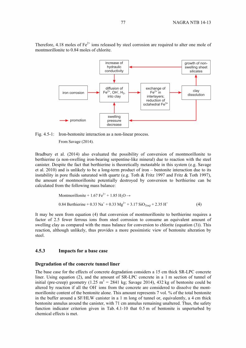
77 NAGRA NTB 14-13
Therefore, 4.18 moles of Fe2+ ions released by steel corrosion are required to alter one mole of montmorillonite to 0.84 moles of chlorite.
Fig. 4.5-1: Iron-bentonite interaction as a non-linear process. From Savage (2014).
Bradbury et al. (2014) also evaluated the possibility of conversion of montmorillonite to berthierine (a non-swelling iron-bearing serpentine-like mineral) due to reaction with the steel canister. Despite the fact that berthierine is theoretically metastable in this system (e.g. Savage et al. 2010) and is unlikely to be a long-term product of iron – bentonite interaction due to its instability in pore fluids saturated with quartz (e.g. Toth & Fritz 1997 and Fritz & Toth 1997), the amount of montmorillonite potentially destroyed by conversion to berthierine can be calculated from the following mass balance:
Montmorillonite + 1.67 Fe2+ + 1.85 H2O →
0.84 Berthierine + 0.33 Na+ + 0.33 Mg2+ + 3.17 SiO2(aq) + 2.35 H+ (4)
It may be seen from equation (4) that conversion of montmorillonite to berthierine requires a factor of 2.5 fewer ferrous ions from steel corrosion to consume an equivalent amount of swelling clay as compared with the mass balance for conversion to chlorite (equation (3)). This reaction, although unlikely, thus provides a more pessimistic view of bentonite alteration by steel.
4.5.3 Impacts for a base case
Degradation of the concrete tunnel liner
The base case for the effects of concrete degradation considers a 15 cm thick SR-LPC concrete liner. Using equation (2), and the amount of SR-LPC concrete in a 1 m section of tunnel of initial (pre-creep) geometry (1.25 m3 = 2841 kg; Savage 2014), 432 kg of bentonite could be altered by reaction if all the OH- ions from the concrete are considered to dissolve the mont-morillonite content of the bentonite alone. This amount represents 7 vol. % of the total bentonite in the buffer around a SF/HLW canister in a 1 m long of tunnel or, equivalently, a 4 cm thick bentonite annulus around the canister, with 71 cm annulus remaining unaltered. Thus, the safety function indicator criterion given in Tab. 4.1-10 that 0.5 m of bentonite is unperturbed by chemical effects is met.
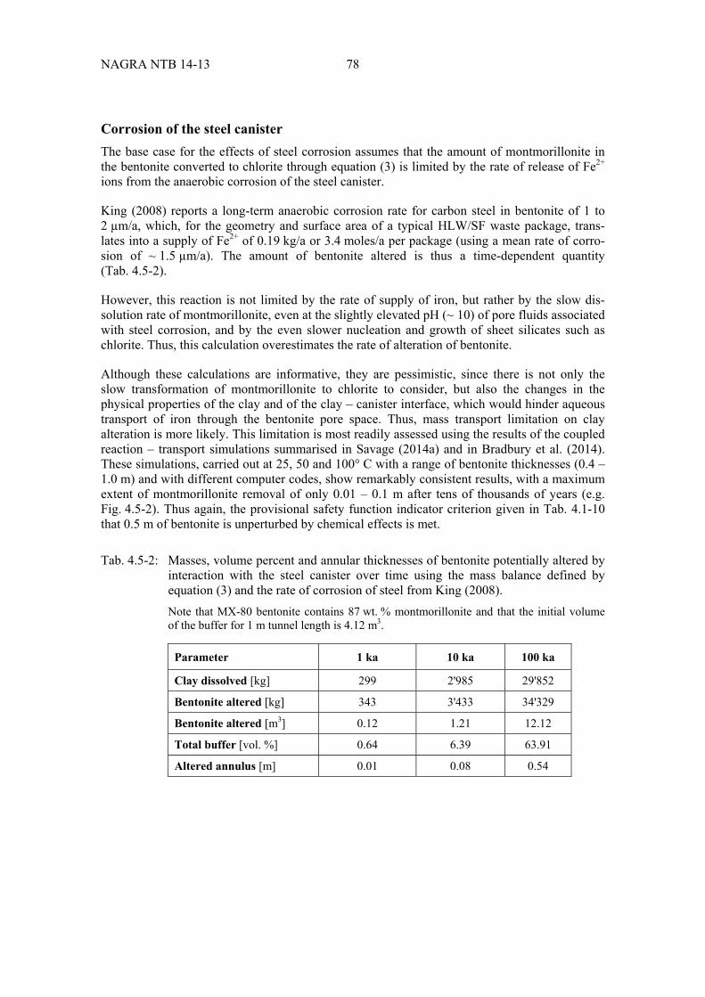
NAGRA NTB 14-13 78
Corrosion of the steel canister
The base case for the effects of steel corrosion assumes that the amount of montmorillonite in the bentonite converted to chlorite through equation (3) is limited by the rate of release of Fe2+ ions from the anaerobic corrosion of the steel canister.
King (2008) reports a long-term anaerobic corrosion rate for carbon steel in bentonite of 1 to 2 µm/a, which, for the geometry and surface area of a typical HLW/SF waste package, trans-lates into a supply of Fe2+ of 0.19 kg/a or 3.4 moles/a per package (using a mean rate of corro-sion of ~ 1.5 µm/a). The amount of bentonite altered is thus a time-dependent quantity (Tab. 4.5-2).
However, this reaction is not limited by the rate of supply of iron, but rather by the slow dis-solution rate of montmorillonite, even at the slightly elevated pH (~ 10) of pore fluids associated with steel corrosion, and by the even slower nucleation and growth of sheet silicates such as chlorite. Thus, this calculation overestimates the rate of alteration of bentonite.
Although these calculations are informative, they are pessimistic, since there is not only the slow transformation of montmorillonite to chlorite to consider, but also the changes in the physical properties of the clay and of the clay – canister interface, which would hinder aqueous transport of iron through the bentonite pore space. Thus, mass transport limitation on clay alteration is more likely. This limitation is most readily assessed using the results of the coupled reaction – transport simulations summarised in Savage (2014a) and in Bradbury et al. (2014). These simulations, carried out at 25, 50 and 100° C with a range of bentonite thicknesses (0.4 – 1.0 m) and with different computer codes, show remarkably consistent results, with a maximum extent of montmorillonite removal of only 0.01 – 0.1 m after tens of thousands of years (e.g. Fig. 4.5-2). Thus again, the provisional safety function indicator criterion given in Tab. 4.1-10 that 0.5 m of bentonite is unperturbed by chemical effects is met.
Tab. 4.5-2: Masses, volume percent and annular thicknesses of bentonite potentially altered by interaction with the steel canister over time using the mass balance defined by equation (3) and the rate of corrosion of steel from King (2008). Note that MX-80 bentonite contains 87 wt. % montmorillonite and that the initial volume of the buffer for 1 m tunnel length is 4.12 m3.
Parameter 1 ka 10 ka 100 ka
Clay dissolved [kg] 299 2'985 29'852
Bentonite altered [kg] 343 3'433 34'329
Bentonite altered [m3] 0.12 1.21 12.12
Total buffer [vol. %] 0.64 6.39 63.91
Altered annulus [m] 0.01 0.08 0.54

79 NAGRA NTB 14-13
Fig. 4.5-2: A typical mineralogical alteration profile from a reaction – transport simulation of
the interaction of a steel canister (right margin) and a 1 m thickness of MX-80 bentonite and a mudstone groundwater (left margin) at 100° C after different times. From Marty et al. (2010).
4.5.4 Impacts for bounding case Type 1
Degradation of the concrete tunnel liner
Here in a first bounding case, the potential alteration associated with the use of an OPC-concrete type tunnel liner is compared with that for an SR-LPC concrete tunnel liner in the base case. The type of bentonite alteration associated with the OPC cement/concrete liner is anticipated to be similar to that described for the SR-LPC concrete liner. However, the greater proportion of cement in OPC concrete as compared with SR-LPC concrete means that from a mass balance perspective, the physical scale of alteration will be greater for the former. Tab. 4.5-1 shows the amounts of concrete and potentially leachable hydroxyl ions in the two types of concrete. It may be seen from this table that the OPC concrete contains more than three times the amount of potentially leachable hydroxyl ions than SR-LPC concrete.
Tab. 4.5-3 shows that the 432 kg of bentonite potentially altered for the SR-LPC liner (repre-senting 7 vol. % of the total bentonite volume, or, equivalently, a 4 cm thick bentonite annulus around the canister), compares with a Figure of 1'475 kg of bentonite potentially destroyed (representing ~ 25 % of the total bentonite volume, or, equivalently, a 14 cm thick bentonite annulus around the canister) for the OPC liner. An annulus of 71 cm would thus remain unaltered, meeting the provisional safety function indicator criterion given in Tab. 4.1-10 that 0.5 m of bentonite is unperturbed by chemical effects.
These mass balance calculations are pessimistic since they do not address likely mass transport limitation of the alteration front (e.g. Savage 2013a). Reaction – transport simulations with porosity feedback (Bradbury et al. 2014) show that, for this system, alteration of the Opalinus Clay may be only a few cm thick after ~ 30 ka and that alteration of the bentonite may extend some 10 cm after a similar time period (Fig. 4.5-3). The interfaces between the concrete liner
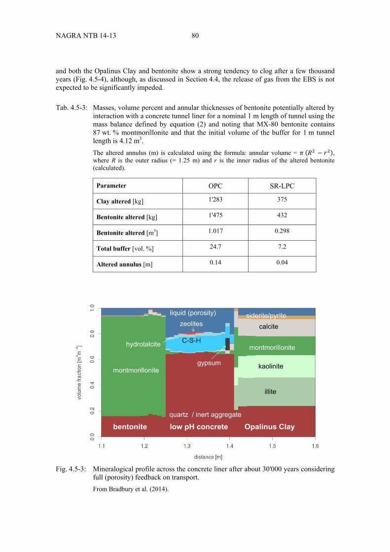
NAGRA NTB 14-13 80
and both the Opalinus Clay and bentonite show a strong tendency to clog after a few thousand years (Fig. 4.5-4), although, as discussed in Section 4.4, the release of gas from the EBS is not expected to be significantly impeded.
Tab. 4.5-3: Masses, volume percent and annular thicknesses of bentonite potentially altered by interaction with a concrete tunnel liner for a nominal 1 m length of tunnel using the mass balance defined by equation (2) and noting that MX-80 bentonite contains 87 wt. % montmorillonite and that the initial volume of the buffer for 1 m tunnel length is 4.12 m3. The altered annulus (m) is calculated using the formula: annular volume = , where R is the outer radius (= 1.25 m) and r is the inner radius of the altered bentonite (calculated).
Parameter OPC SR-LPC
Clay altered [kg] 1'283 375
Bentonite altered [kg] 1'475 432
Bentonite altered [m3] 1.017 0.298
Total buffer [vol. %] 24.7 7.2
Altered annulus [m] 0.14 0.04
Fig. 4.5-3: Mineralogical profile across the concrete liner after about 30'000 years considering full (porosity) feedback on transport. From Bradbury et al. (2014).
montmorillonite
montmorillonite
illite
kaolinite
calcitesiderite/pyrite
quartz / inert aggregate
C-S-Hhydrotalcite
liquid (porosity)
bentonite low pH concrete Opalinus Clay
zeolites
gypsum

81 NAGRA NTB 14-13
Fig. 4.5-4: Porosity evolution at t = 0, 10 and 30.8 ka. From Bradbury et al. (2014).
Corrosion of the steel canister
Although more pessimistic cases than that considered for the base case could be evaluated (e.g. the conversion of montmorillonite to berthierine), replacement of montmorillonite in the buffer by non-swelling minerals would impact upon the self-sealing aspect of the buffer only in the very long-term and it is unlikely to affect its low hydraulic conductivity and thus safety-relevant properties.
4.5.5 Impacts for bounding case Type 2
Degradation of the concrete tunnel liner
Savage (2014) evaluated the effects of different thicknesses of the concrete tunnel liner upon alkaline alteration of bentonite to ascertain whether a cut-off point exists, i.e. whether there is a certain liner thickness beyond which the unaltered bentonite is too thin to perform its safety functions. The same approach as that described above is employed, i.e. a mass balance using equation (2). The liner is assumed to be constructed from an OPC-type concrete.
The results of the calculations are shown graphically in Fig. 4.5-5. It may be seen from these data that, even in the case of a (unfeasibly large) 1 m thick OPC concrete tunnel liner, an annu-lus of 0.35 m of unaltered bentonite would still remain around the canister despite the pessi-mism of the mass balance approach.

NAGRA NTB 14-13 82
Fig. 4.5-5: Effect of an OPC concrete tunnel liner thickness on the thickness of alteration of bentonite.
4.5.6 Concluding remarks on chemical interactions
Chemical interactions in a repository for high-level waste and spent fuel are mainly related to the corrosion of steel and degradation of cement. The impacts of these reactions were assessed on a basis of kinetics and diffusion (for corrosion-related interactions) on a mass balance basis (for the degradation of concrete). It is shown that even under extreme assumptions enough bentonite (annulus of unaltered bentonite > 0.5 m) will be present to fulfil the safety require-ments as stated in Tab. 4.1-10.
4.6 Dose calculations for specific repository-induced effects
4.6.1 Temperature
The temperature evolution in the HLW repository is primarily a result of the heat generated by SF and HLW. The temperature at the bentonite buffer/canister interface is calculated to decline to < 100° C after about 100 years (Senger et al. 2014), in the case of the reference canister spacing. The temperature increase in the near field and in the adjacent host rock with respect to ambient rock temperature due to radiogenic heat is reduced to less than about 10° C at times greater than 10'000 years (i.e. the canister lifetime). Therefore, the relevant safety function indicator criterion is met, indicating that mineralogical stability of the host rock will be main-tained. Furthermore, the effects of elevated temperatures on radionuclide sorption on clay minerals, on radionuclide solubility and on radionuclide diffusion are limited. The influence of temperature on sorption is discussed in Baeyens et al. (2014), on solubility in the bentonite near field in Berner (2014) and on diffusion in Van Loon (2014). The effect of uncertainties in sorption coefficients, solubility limits and diffusion coefficients (including the estimated contri-bution of increased temperature to that uncertainty) on the calculated dose rates are presented in Nagra (2014c).Dose calculations show that thermally increased diffusion coefficients in the geosphere might have the largest impact on the maximum dose.
4.6.2 Rock mechanics and EDZ evolution
Owing to the swelling capacity of the bentonite buffer and the self-sealing properties of the Opalinus Clay, the hydraulic conductivity of the EDZ in the HLW repository will be low in the long-term, when any radionuclide releases are expected to occur. For the dose calculations,

83 NAGRA NTB 14-13
radionuclide transport is typically assumed to occur perpendicularly to the tunnel axis. How-ever, horizontal transport in or near the interface between the emplacement drifts and the adjacent host rock in the direction of the axis of the tunnels has also been analysed in Poller et al. (2014). The analysis shows that even hypothetical, unrealistically high hydraulic conductivi-ties of the EDZ will not result in unacceptable doses26.
The effect of porewater squeezing due to tunnel convergence was addressed in Nagra (2002b) and found to have a negligible effect on calculated dose rates.
4.6.3 Transport of gases and its effect on dose
Experimental evidence shows that gas will flow along the EDZ and, in addition, extensive modelling efforts (discussed in the previous sections and in Papafotiou & Senger 2014c, Nagra 2002a, Nagra 2002b, Nagra 2004, Nagra 2008d, Nagra 2011) have shown that even without considering the gas flow through the EDZ, the gas pressure build-up from the anaerobic corro-sion of the steel canisters does not affect the long-term barrier performance of the host rock.
Based on the above mentioned references, it can be concluded that gas pressure build-up and the resulting porewater displacement will not lead to high and sustained water flow rates from the emplacement drifts and along the repository tunnel system. The radiological consequences of gas-induced water flow will thus be no higher than those obtained in Poller et al. (2014) and hence far below the regulatory protection criterion.
For the case of potential volatile 14C transport, bounding calculations in Nagra (2002b) and in Nagra (2004) have shown that co-transport of 14C with hydrogen, if it occurred, would lead to acceptably low dose rates.
Overall, it can thus be concluded that gas pressure build-up will not lead to unacceptable dose rates.
4.6.4 Chemical interactions and its effect on dose
The interaction between the cement liner and the bentonite/Opalinus Clay creates a steep pH gradient that leads to mineralogical changes in both the bentonite and the Opalinus Clay, even if a low-pH cement is used. As discussed in Section 4.5, based on mass balance considerations (Savage et al. 2014) and reactive transport calculations (Bradbury et al. 2014), it can conser-vatively be assumed that about 0.2 m of bentonite and less than 0.1 m of Opalinus Clay could be affected by such changes. Given that this is less than the 0.5 m bentonite as defined by the indicator criteria, and it is also small compared with the overall thickness of the Opalinus Clay, no significant effects on dose rates are to be expected.
Mineralogical changes due to iron – bentonite interactions in the inner zone of the bentonite buffer were conceptualised in the dose calculations made in Nagra (2014c) by assuming:
the same porosity is available to migrating cations and anions in the zone
the effective diffusion coefficients of 14Corg can be conservatively taken as a proxy for the effective diffusion coefficient of all anions, while, for non-anions (cations and neutral species), the effective diffusion coefficients are the same as for unaltered bentonite
26 Furthermore, radionuclide transport along the cement liner of the HLW emplacement rooms is effectively preven-
ted by the presence of intermittent sealing sections (see Section 2.1, Fig. 2.1-3).

NAGRA NTB 14-13 84
sorption coefficients that are scaled by a factor of 1/10 to account for a reduction in the sorption capacity of the zone
solubility limits in the zone that are set to the upper limits of the expected values for the narrow range of pH and redox conditions in bentonite
An increase in salinity of the porewater will affect the sorption of those cations that sorb through cation exchange. However, because the effects of an increase in salinity on diffusion and on sorption through cation exchange largely offset each other, the transport of these radio-nuclides is affected very little (Cloet et al. 2014).
The sorption of radionuclides by surface complexation is not affected by an increased salinity. A few radionuclides may form complexes with Cl- and SO4
2- in high salinity porewater, which are taken into account in the corresponding sorption and solubility databases used for dose calculations (Baeyens et al. 2014, Berner 2014). Solubility limits in a bentonite environment are defined for the narrow range of pH and redox conditions in bentonite, as noted above.
The internal degradation of cement and the degradation of organics in the ILW are taken into account in the compilation of the cement sorption database (Wieland 2014). The dose calcula-tions reported in Nagra (2014c), which used this database (including uncertainties) as input, showed that these effects will not lead to unacceptable consequences.
4.7 Evolution of the repository
In the following sections a brief overview is given of the expected evolution of conditions in a HLW repository in Opalinus Clay. Main references are Senger (2014), Savage (2013a) and Bradbury et al. (2014). The evolution of the ILW repository is assumed to be analogous to the L/ILW repository which is described in Leupin et al. (2016).
The pre-excavation phase
The undisturbed in-situ conditions of the host rock domain, geosphere and biosphere in the can-didate siting regions will be investigated / assessed in an extensive field campaign prior to the excavation of the underground structures. For the Opalinus Clay much of the understanding already exists based on studies summarised in Entsorgungsnachweis (Nagra 2002b) and through ongoing field investigations and studies at the Mont Terri URL.
Safety-relevant parameters of the undisturbed system provide a baseline for evaluating all host rock and coupled host rock / near-field processes.
During the construction of the access tunnel and shafts, rock parameters are continuously collec-ted to update safety analysis models. Host rock properties and THM state conditions (pore pressure stress, temperature, and saturation) are finally assessed in the test area (repository URL; see Fig. 2.1-2). This facility allows for an extensive experimental programme and for a final set of host-rock parameter values to be determined. The URL is also used to study aspects such as excavation damage, tunnel support techniques and interaction of backfills with the host rock.
A pilot facility is excavated and instrumented and waste canisters are emplaced followed by backfilling. Instrumentation of the pilot facility allows monitoring the evolution of the reposi-tory analogue after closure.
85 NAGRA NTB 14-13
The excavation and waste emplacement phase
The excavation phase starts with the excavation of the access to the HLW repository, followed by the construction of operations tunnels. Waste emplacement rooms are then constructed, including installation of the necessary tunnel support measures. Each room remains open for only a short period of time until waste emplacement and backfilling occurs. A continuing sequence of excavation, waste emplacement and backfilling occurs so that a limited number of emplacement rooms are open at any given time. This phase is characterised by excavation-rela-ted perturbations such as formation of an EDZ, desiccation of the surface region of the EDZ and cooling of the rock as a result of ventilation, the creation of a high hydraulic gradient, potential import of bacteria, oxidation of exposed minerals, mineral precipitation within the open pore space and initiation of corrosion and alteration of materials used for tunnel support etc.
The excavation phase is important with regard to long-term safety as several safety-relevant parameters are defined or can be modified during excavation, operation, emplacement of the waste and backfilling operations, although these changes to the host rock are restricted to within a few metres of the excavation.
The thorough baseline characterisation – description of the initial state of the host rock – is instrumental for understanding the evolution of safety-relevant parameters and processes during the observation phase. Important aspects include:
During excavation, breakouts and EDZ formation must be minimised and needs to be care-fully observed for limiting damage of the host rock.
Tunnel support must limit further EDZ formation but should comply with long-term safety principles.
The bentonite buffer must have a density high enough to generate a sufficient swelling pressure, thus contributing to EDZ self-sealing under fully saturated conditions, provide sufficient sorption capacity for radionuclide retention upon canister breaching and a low enough swelling pressure that gas generated by canister corrosion can migrate through the buffer.
Seals and plugs must comply with the hydraulic requirements.
The emplacement rooms may be supported after construction by a shotcrete liner and steel arches.
The process of waste emplacement begins with the emplacement of the first canister together with its bentonite pedestal. The granular bentonite buffer material (water content about 5 %) is emplaced around the canister. The steps are repeated. If a shotcrete liner has been installed, intermediate seals are installed between every tenth canister and the emplacement of canisters, backfilling and sealing continues until the tunnel is filled. A bentonite seal and temporary plug is placed at the entrance to the tunnel.
The resaturation phase (0 to 100 years after emplacement)
For SF/HLW canisters, the initial heat output is limited to 1'350 W, which will result in a tem-perature at the canister interface with the backfill of about 130° C within about ten years (Senger et al. 2014). The temperature of the rock at the room boundary will reach its maximum (about 90° C) after about 100 years. The bentonite buffer will become saturated within about 50 to 100 years, when porewater pressures within the backfill are much lower compared to those in the surrounding host rock. Heat transport to the far-field rock will increase the temperature to the maximum value of ~ 75° C at a distance of 20 m above the tunnels. The porewater pressure

NAGRA NTB 14-13 86
in the rock within about 20 m of the tunnels will increase to as much as 70 % of the lithostatic pressure above the initial host rock value after about 100 years as a result of the thermal expan-sion of porewater and rock and the low hydraulic conductivity. After full saturation of the buffer, pore pressures in the buffer will increase to those in the surrounding host rock.
Gas generation through corrosion of the steel used in the tunnel support and of the canisters will begin, although most of the gas produced in the first hundred years will dissolve (Papafotiou & Senger 2014c).
As defined here, this phase ends with the close-to-full saturation of the buffer (a residual gas saturation of 1 – 2 % is expected in the buffer at the end of the resaturation phase). By then, all construction and operation tunnels are backfilled and sealed. During this phase the access tunnel and shafts are kept open. The resaturation phase largely coincides with the observation phase of the pilot repository which is thoroughly characterised to identify any deviation from the expected evolution. Only the pilot repository will be monitored.
After complete saturation27 of the near field (100 to 1'000 years after emplacement)
Between 100 and 1'000 years, the canister surface temperature will decline from 80° C to 60° C. By about 1'000 years, the near-field rock temperature will also decline to about 60° C. Pore-water pressure will reach its maximum in the near field of about 5 MPa above the initial forma-tion pressure as a result of the coupled effects of gas generation (dominated by corrosion of tun-nel support materials) and thermal expansion. In the far field (20 m from tunnels and beyond), the porewater pressure will further rise (up to about 500 years) and then begin to decline and in the confining units an insignificant increase in pore pressure will have occurred. The thermal expansion of the rock sequences above the repository footprint will result in a heave of the ground surface in the 0.2 m range (Senger et al. 2014).
Anaerobic corrosion of the canister and steel material used for tunnel support will continue.
The end of the thermal period (1'000 to 10'000 years after emplacement)
Temperatures in the near field will decline from about 60° C to about 50° C from 1'000 to 10'000 years and in the far-field rock will decrease to 10° C above ambient rock values. Corro-sion of steel materials used for tunnel support will cease after a few thousand years, although gas generation from the thick-walled disposal canisters will continue. The gas production rate is thus reduced and porewater pressure falls by several MPa in the near- and far-field rock due the combined thermal and gas production effects.
Based on our current understanding compaction of the bentonite around the canister is not expected to occur as the adjacent rock reconsolidates. The EDZ is expected to be largely self-sealed, although increased gas pressures may keep pathways open.
The cementitious liner will eventually degrade due to the resaturation with porewater and pre-cipitates might invade pores at the interface with Opalinus Clay and bentonite (skin formation). A high pH plume is expected to affect a few centimetres of the host rock and bentonite (Savage 2013a).
Corrosion of the canister has produced mobile iron species that migrate through the bentonite and form iron-rich clay minerals or Fe(II) precipitates around the canisters.
27 Note that a residual gas saturation of 1 – 2 % remains in the buffer at the end of the resaturation phase.

87 NAGRA NTB 14-13
Canister breaching and radionuclide transport period (10'000 years and beyond)
Beyond 10'000 years, the temperatures will decline gradually from 50° C back to ambient rock values. Though some of the canisters are now expected to be locally breached, corrosion and gas production will continue for tens of thousands of years. As a result, hydrogen will conti-nuously be transported through the backfill into the EDZ and host rock and mobile Fe (II) will diffuse into the bentonite. The porewater pressure in the rock surrounding the rooms will increase again slightly as the canister corrosion continues, until corrosion is complete after about 50'000 – 100'000 years.
Eventually, the canister will be breached and porewater will contact the waste matrix and radio-nuclides will diffuse through the saturated buffer and into the host rock. Depending on the chemical forms and half-lives of the radionuclides, the transport distances into the rock will vary. Safety analysis calculations show that negatively charged non-sorbing long-lived nuclides (such as 129I, 36Cl and 79Se) might migrate as far as the biosphere after several hundred thousand years.
4.8 Synthesis of the system behaviour under site conditions
Deep geological repositories are designed to avoid, minimise or mitigate the impact of poten-tially detrimental repository-induced effects on long-term safety. In the case of clay rock with a thickness of about 100 m, detrimental effects are limited because chemical and mechanical impacts are largely confined to the rock immediately adjacent to the excavation, thermal im-pacts are controllable by limiting the heat load (canister loading and spacing, spacing between emplacement rooms) and gas effects are mitigated by ensuring acceptably low gas production rates and by the natural tendency for gas entry pressures along the excavations and the EDZ to be lower than those to the undisturbed rock. Specific measures that are part of the current refe-rence design are discussed in Chapter 5 in relation to their significance with respect to reposi-tory-induced effects.
The SF/HLW emplacement drifts are designed in such a way that the formation of excavation damaged zones is limited. This is achieved by restricting the size of the excavations (maximum excavated diameter) and the depth of the repository, using a low-deformation, controlled con-struction and excavation method (with rapid installation of appropriately dimensioned support measures) and by the fact that the excavations will be backfilled relatively soon after con-struction (within a few years) with a swelling backfill material. At expected repository depths, the drifts will need to be supported to ensure stability and worker protection; this will prevent rock falls and further extension of the EDZ. Based on the modelling results described earlier in this chapter, it can be concluded that the extent of the EDZ around the HLW emplacement drifts will not exceed in any case a thickness of one drift diameter and that the hydraulic conductance of the EDZ around emplacement drifts, access tunnels and shafts will not exceed a value of 10-7 m3/s. Self-sealing of the EDZ and low hydraulic gradients along the tunnels will result in negligible radionuclide transport by the EDZ pathway.
When designing and assessing the performance of a HLW repository, the relevant chemical interactions are taken into account. With the current reference design, it is expected that degra-dation of the concrete tunnel liner and corrosion of the steel canister and other supporting structures will lead to some alteration of the bentonite buffer and Opalinus Clay. These detri-mental effects are taken into account in dose calculations and have been found not to have a significant impact on the calculated dose rates.

NAGRA NTB 14-13 88
The results from the simulations reported in Section 4.4 indicate that, for the reference gas generation rates, the gas transport capacity of the Opalinus Clay is sufficiently high to dispel gas without invoking pathway dilation as a gas transport mechanism and without causing damage to the rock. Even if potential transport pathways for gas along the excavations and EDZ are dis-regarded, overpressures that would lead to the onset of pathway dilation are reached only in cases combining conservative gas generation rates with a low-permeability host rock, and these overpressures are still insufficient to cause rock damage. It is noted that such calculations do not incorporate transport of gas along the EDZ, which has a lower gas entry pressure than undis-turbed Opalinus Clay (Papafotiou & Senger 2014c). As discussed in Chapter 5, possibilities exist for lowering gas-production rates, should this be required.
The effects of heat from HLW on the engineered and geological barriers cannot be completely eliminated, but can be kept low by ensuring a sufficient duration of interim storage, limiting canister loading and a suitable canister emplacement density.
In Appendix A, it is shown that the main conclusions regarding the repository-induced effects of a combined L/ILW and HLW repository are basically the same as for separate L/ILW and HLW repositories. The mutual influence between the L/ILW and HLW sections of the repository can be limited by ensuring an adequate spatial separation between the two sections, although this increases the space required for the combined repository, which may in turn affect the suitability of a given siting area. At present, the reference minimum horizontal distance between the emplacement rooms of the two sections is taken to be 200 m. This value roughly corresponds to the distance between the SF/HLW and ILW parts of the HLW repository.

89 NAGRA NTB 14-13
5 Engineering options for mitigating repository-induced effects on long-term safety
The disposal system described in this report is founded on a system of passive barriers that pro-vide multiple safety functions which are well understood and ultimately result in robustness. The barriers include the Opalinus Clay host rock, its surrounding geological setting and also the repository waste forms, canisters and backfill. The attributes of these barriers intrinsically favour safety, and also avoid, minimise or mitigate the impact of potentially detrimental reposi-tory-induced effects and their associated uncertainties.
Repository-induced effects and their associated uncertainties have been investigated and dis-cussed in detail in this report. It is concluded that, although not all such effects can be avoided, sufficient safety can nonetheless be achieved. The main arguments to support this conclusion are as follows:
1. For the chosen disposal system, many repository-induced effects can be ruled out as poten-tially safety-relevant through a preliminary assessment of their impact. In particular, quali-tative reasoning and quantitative considerations based on prior calculations have shown that, for the chosen disposal system, their domain of influence and/or their effects on radio-nuclide release are very limited (Chapter 3).
2. Where significant effects on those natural or engineered barriers could not be excluded, a wide range of additional detailed and rigorous analyses have been carried out to quantify their impact. Most of the analyses indicated that the repository barriers would continue to provide their designated safety functions, in spite of a number of conservative or pessimistic assumptions, demonstrating the robustness of the disposal system with respect to the detri-mental phenomena and uncertainties considered (Chapter 4).
3. Dose calculations taking into account the potentially detrimental impact of the most signi-ficant repository-induced effects (including associated uncertainties) have illustrated their overall significance to repository perfomance (Section 4.6).
Furthermore, the disposal system design incorporates flexibility to allow for different siting con-ditions, and a range of engineering options exist to further mitigate repository-induced effects, such as measures to reduce gas pressure build-up in the ILW part of the repository and avoid critical values that could potentially harm the integrity of the host rock. These measures are des-cribed further in the following paragraphs.
Engineering options to mitigate temperature-related effects
Decay heat from SF and HLW will increase temperatures within and around the repository for long periods of time. The maximum temperatures reached in the various disposal system com-ponents and the time dependency of the temperatures are determined principally by the heat out-put of the wastes, the selected repository layout, the thermal properties of the bentonite buffer and the surrounding rock (e.g. thermal conductivities and heat capacities) and the ambient tem-perature of the rock at repository depth.
Maximum temperatures can, if necessary, be limited by decreasing canister heat output (e.g. by reducing canister loading and/or increasing the storage time of the SF/HLW prior to emplace-ment in the repository) and/or increasing the spacing between canisters and/or increasing the spacing between emplacement drifts and/or by reducing depth.

NAGRA NTB 14-13 90
Engineering options to mitigate effects related to rock mechanics
The stress redistribution during tunnelling in indurated clays (e.g. shales and claystones) requires support structures such that the formation of an EDZ can be limited. In general the maintenance of a compressive regime during excavation may allow controlling the stress –failures and stress/structure failures. Such a compressive regime can be achieved by a massive liner supporting the excavated tunnels or optimised excavation technique regarding the extent of the damage of the rock.
In a geological repository a massive liner construction is nonetheless not desirable (see discus-sion on chemical effects and optimisation of the repository depth). The geometry and extent of the EDZ in indurated clays is not only controlled by the primary stress tensor, rock anisotropy (stiffness and strength) and the heterogeneity of the rock mass but also by the excavation tech-nique, tunnel geometry, tunnel support and ground interaction. By the combination of these parameters the emplacement of a massive liner support can be avoided and low to medium support measures might be enough to limit the formation of the EDZ.
During operations time, the ventilation regime can be optimised in order to minimise cyclic deformations, which may be triggered by seasonal temperature and humidity variations.
Engineering options to mitigate effects related to gas pressure build-up
Steel presents a number of advantages as a canister material for nuclear waste disposal. It is widely available and permits canisters to be manufactured at reasonable cost with relatively thick walls that provide mechanical strength and contribute to radiation shielding. Steel permits welding to be used for sealing of canisters. The most critical issue with steel is its corrosion rate and the associated rate of gas production. Given the compressible nature of repository-generated gas, additional drifts and tunnels, such as those present in a combined L/ILW and HLW reposi-tory, can reduce the gas pressure build-up by increasing the gas storage volume (see Appen-dix A). The use of steel (e.g. in supporting structures) could potentially be reduced, although there are probably only few existing materials that could be used as alternatives. On the other hand, some of the structural elements such as the rails could conceivably be removed before backfilling the emplacement rooms.
Other potential metallic canister materials, such as copper, that could give lower gas production rates are being evaluated (Landolt et al. 2009). Non-metallic, inorganic materials (ceramics), in particular oxides, also present certain advantages in terms of low degradation rates due to their thermodynamic stability, but there are issues of concern regarding their mechanical properties.
Engineering options to mitigate chemical impacts
Chemical conditions in the repository, as well as their temporal changes, are driven by the inter-actions between hydrated cement, steel, aggregates and clays. Because of the chemical nature of the major materials involved, two processes dominate: reactions of cement minerals with aggre-gate/clays and the corrosion of iron.
The cement recipe can be adjusted to some degree to reduce the amount of alkali leached into the clay and thus reduce the pH of the porewater. It can also be adjusted to resist sulphate attack by increasing the amount of silica and thus prevent the formation of ettringite minerals.
The possibilities to reduce the use of steel in the repository, and hence issues related to the corrosion of iron, have been described above.
91 NAGRA NTB 14-13
Engineering options to mitigate the mutual influence between the sections of a combined repository
In Appendix A, it is shown that the main conclusions regarding the repository-induced effects in a combined L/ILW and HLW repository are basically the same as for separate L/ILW and HLW repositories. The mutual influence between the L/ILW and HLW sections of the repository can be limited by ensuring an adequate spatial separation between the two sections, although this increases the space required for the combined repository. In the current stage of planning, the reference minimum horizontal distance between the emplacement rooms of the two sections is taken to be 200 m.
Optimisation of repository depth
In Nagra (2008b) requirements were formulated for identifying suitable repository and site con-figurations; the focus was set among others on the spatial geological conditions. These included thickness at suitable depth (minimum depth with respect to surface erosion, vertical glacial erosion and rock decompaction, maximum depth in terms of engineering requirements) and lateral extent (taking into account regional geological features), as well as the local geological-tectonic situation.
The evolution of the HLW repository and the resulting repository-induced effects might influ-ence the overall performance of the repository: with increasing depth the higher degree of rock compaction makes the rock less permeable to gas (Section 4.4) and the prevailing higher tem-perature (Section 4.2) leads to higher porewater pressures. But these processes might be coun-terbalanced by increased rock strength at greater repository depths. Increasing effective stresses at greater repository depths will also result in a need for substantial engineered structures for supporting the emplacement drifts which will affect the overall performance of the bentonite (Nagra 2014e).
With increasing depth a larger EDZ might results from stress redistribution during excavation leading to enhanced pore volume around the near field. This additional pore volume needs to be minimised in order to not decompact the emplaced bentonite.
Feasibility and safety can – in principle – be ensured at greater depth. By following a pre-cautionary approach, however, the repository depth should be limited to avoid damage to the host rock.
As the undisturbed rock temperature in the Opalinus Clay increases by 4 – 6° C/100 m with increasing siting depth as determined by the geothermal gradient, stronger ventilation of the underground installations is required during the construction and operational phase. The hydrau-lic gradients and temperature gradients induced by the ventilation in the underground installa-tions cause the host rock to cool down and increasingly dry out, which can lead to formation of shrinkage cracks. The higher the temperature differences, the more pronounced these processes are. The influence of ventilation on the long-term evolution of the EDZ therefore increases with depth. For example, loss of ventilation can lead to additional tunnel convergence during the operational phase.
In general, the average effective stress increases with greater depth and, with this, the form and extent of the EDZ induced by tunnel construction. A decrease in the swelling index with increasing depth was also observed for the Opalinus Clay. The combination of all these pro-cesses bears the risk that, as depth increases, the resulting secondary porosity does not fully heal. These processes can be counteracted with engineering measures, but these usually have a negative impact on the homogenisation of the bentonite, as explained below.

NAGRA NTB 14-13 92
The impact of the evolution of the safety-relevant properties of the bentonite backfill on the safety of a repository can only be evaluated when the distribution of the material properties can be assumed to be as homogeneous as possible. The homogenisation of the bentonite backfill is caused inter alia by the swelling of montmorillonite during the resaturation of the repository through the uptake of porewater. The uptake of porewater and the resulting swelling pressure depend, among other things, on the chemical composition and temperature of the porewater.
With increasing depth and the associated increase in the ambient temperature of up to 55° C, the swelling pressure can be reduced by up to 1 MPa. The combination of the additional installa-tions required at greater depth to ensure repository safety, which have a negative effect on the swelling pressure of the bentonite at interfaces, and the increased ambient temperature result in a poorer homogenisation of the bentonite backfill. The drop in swelling pressure and the increase in water activity associated with higher temperatures are also generally favourable for the development of microbial perturbations.
93 NAGRA NTB 14-13
6 References
Alcolea, A., Kuhlmann, U., Lanyon, G.W. & Marschall, P. (2014): Hydraulic conductance of the EDZ around underground structures of a geological repository for radioactive waste – A sensitivity study for the candidate host rocks in the proposed siting regions in Northern Switzerland. Nagra Arbeitsber. NAB 13-94.
Åkesson, M., Kristensson, O., Börgesson, L., Dueck, A. & Hernelind, J. (2010b). THM modelling of buffer, backfill and other system components. Critical processes and scenarios. SKB Tech. Rep. TR-10-11. Svensk Kärnbränslehantering AB.
Allen, C.C. & Wood, M.I. (1988): Bentonite in nuclear waste disposal: a review of research in support of the Basalt Waste Isolation Project. Applied Clay Science 3, 11-30.
Baeyens, B., Thoenen, T., Bradbury, M.H. & Marques Fernandes, M. (2014): Sorption data bases for argillaceous rocks and bentonite for the Provisional Safety Analyses for SGT-E2. Nagra Tech. Rep. NTB 12-04.
Benson, S.M., Hepple, R., Apps, J., Tsang, C.F. & Lippmann, M. (2002): Lessons learned from natural and industrial analogues for storage of carbon dioxide in deep geological forma-tions. Lawrence Berkeley National Laboratory, Report No. LBNL-51170, Berkeley.
Berner, U. (2014): Solubility of radionuclides in a bentonite environment for provisional safety analyses for SGT-E2. Nagra Tech. Rep. NTB 14-06.
BFE (2008): Sachplan geologische Tiefenlager: Konzeptteil. Bundesamt für Energie BFE, Bern.
Bossart, P. & Nussbaum, C. (2007): Mont Terri Project – Heater experiment, engineered barrier emplacement and ventilation experiment. Reports of the Swiss Geological Survey / Berichte der Landesgeologie 1. Swisstopo, Wabern.
Bradbury, M., Berner, U., Curti, E., Hummel, W., Kosakowski, G. & Thoenen, T. (2014): The long term geochemical evolution of the nearfield of the HLW repository. Nagra Tech. Rep. NTB 12-01.
Calder, N. & Avis, J. (2006): View User Manual, Version 4.0, 2006. Intera Engineering, Ottawa, Canada.
Carlson, L., Karnland, O., Oversby, V.M., Rance, A., Smart, N., Snellman, M., Vähänen, M. & Werme, L.O. (2007): Experimental studies of the interactions between anaerobically corroding iron and bentonite. Physics and Chemistry of the Earth 32, 334-345.
Charlet, L. & Tournassat, C. (2005): Fe (II)-Na (I)-Ca (II) cation exchange on montmorillonite in chloride medium: Evidence for preferential clay adsorption of chloride–metal ion pairs in seawater Aquatic Geochemistry 11/2, 115-137.
Cloet, V., Schwyn, B., Baeyens, B., Curti, E., Diomidis, N., Johnson, L.H., Mibus, J., van Loon, L.R. & Wieland, E. (2014): Einfluss der Salinität des Porenwassers der Wirtgesteine auf die Langzeitsicherheit der Tiefenlager. Nagra Arbeitsbericht NAB 14-09.
CSA (2006): Storage of hydrocarbons in underground formations. Z341 Series-06. Canadian Standards Association, Ontario.

NAGRA NTB 14-13 94
Darcis, M., Poller, A., Mishin, Y., Poppei, J. & Mayer, G. (2014): Modellrechnungen zur Tem-peraturentwicklung bei der Einlagerung von radioaktiven Abfällen in das SMA-Lager und das LMA-Lager. Nagra Arbeitsber. NAB 14-31.
De Windt, L., Marsal, F., Tinseau, E. & Pellegrini, D. (2008): Reactive transport modeling of geochemical interactions at a concrete/argillite interface, Tournemire site (France). Physics and Chemistry of the Earth 33, S295-S305.
Didier, M., Leone, L., Greneche, J.M., Giffaut, E. & Charlet, L. (2012): Adsorption of hydrogen gas and redox processes in clays. Environmental Science & Technology 46/6, 3574-3579.
Diomidis, N. (2014): Scientific basis for the production of gas due to corrosion in a deep geo-logical repository. Nagra Arbeitsber. NAB 14-21.
ENSI (2010): Anforderungen an die provisorischen Sicherheitsanalysen und den sicherheits-technischen Vergleich. Sachplan geologische Tiefenlager, Etappe 2. ENSI 33/075 (April 2010). Eidgenössisches Nuklearsicherheitsinspektorat ENSI, Brugg.
ENSI (2011): Stellungnahme zu NTB 10-01 "Beurteilung der geologischen Unterlagen für die provisorischen Sicherheitsanalysen in SGT Etappe 2". ENSI 33/115 (März 2011). Eid-genössisches Nuklearsicherheitsinspektorat ENSI, Brugg.
Evans, D.J. (2008): An appraisal of underground gas storage technologies and incidents, for the development of risk assessment methodology. BGS research report RR605. British Geo-logical Survey, Health and Safety Executive HSE.
Fernández, R., Cuevas, J. & Mäder, U.K. (2009): Modelling concrete interaction with a bento-nite barrier. European Journal of Mineralogy 21, 177-191.
Fritz, S.J. & Toth, T.A. (1997): An Fe-berthierine from a Cretaceous laterite. Part II: Estimation of Eh, pH and pCO2 conditions of formation. Clays and Clay Minerals 45, 580-586.
Frugier, P., Gin, S.,. Minet, Y, Chave, T., Bonin, B, Godon, N., Lartigue, J.-E, Ayral, A., De Windt, L., Santarini, G. (2008): SON68 nuclear glass dissolution kinetics:Current State of knowledge and basis of the new GRAAL Model, Journal of Nuclear Materials, 380, 8-21.
Gaboreau, S., Lerouge, C., Dewonck, S., Linard, Y., Bourbon, X., Fialips, C.I., Mazurier, A., Pret, D., Borschneck, D., Montouillout, V., Gaucher, E.C. & Claret, F. (2012): In-situ interaction of cement and shotcrete with claystones in a deep disposal context. American Journal of Science 312, 314-356.
Gaucher, E., Blanc, P., Matray, J.M. & Michau, N. (2004): Modeling diffusion of an alkaline plume in a clay barrier. Applied Geochemistry 19, 1505-1515.
Gaus, I., Czaikowski, O., Garitte, B., Gens, A., Kuhlmann, U. & Wieczorek, K. (2012): Design and predictive modeling of the HE-E test. PEBS Deliverable D3.2-1. Nagra Arbeitsber. NAB 12-03.
Geomechanica (2013): Extent and shape of the EDZ around underground structures of a geolo-gical repository for radioactive waste – A sensitivity study for the Opalinus Clay forma-tion in the proposed siting regions in Northern Switzerland. Nagra Arbeitsber. NAB 13-78.

95 NAGRA NTB 14-13
Grauls, D. (1999): Overpressures: Causal mechanisms, conventional and hydromechanical approaches. Oil & Gas Sci. and technol. Rev. IFP 54/6, 667-678.
Gribi, P. & Gautschi, A. (2001): Lager BE/HAA/LMA im Opalinuston: Salzanreicherung im Bereich der Tunnelwände. Unpubl. Nagra Internal Rep.
Gribi, P., Johnson, L.H., Suter, D., Smith, P.A., Pastina, B. & Snellman, M. (2008): Safety assessment for a KBS-3H spent nuclear fuel repository at Olkiluoto. SKB Process Rep. R-08-36. Swedish Nuclear Fuel and Waste Management Company, Stockholm.
Hermansson, H.-P. (2004): The stability of magnetite and its significance as a passivating film in the repository environment. SKI Report 2004:07. Swedish Nuclear Power Inspectorate, Stockholm.
Ibrahim, M.A., Tek, M.R., Katz, D.L. (1970): Threshold Pressure in Gas Storage. American Gas Association. Arlington, United States.
Johnson, L.H. & King, F. (2003): Canister options for the disposal of spent fuel. Nagra Tech. Rep. NTB 02-11.
Johnson, L.H., Niemeyer, M., Klubertanz, G., Siegel, P. & Gribi, P. (2002): Calculations of the temperature evolution of a repository for spent fuel, vitrified high-level waste and intermediate level waste in Opalinus Clay. Nagra Tech. Rep. NTB 01-04.
Johnson, L., Gaus, I., Wieczorek, K., Mayor, J.C., Sellin, P., Villar, M.V., Samper, J., Cuevas, J., Gens, A., Velasco, M., Turrero, M.J., Montenegro, L., Martin, P.L. & Armand, G. (2014): Integration of the short-term evolution of the engineered barrier system (EBS) with the long-term safety perspective (Deliverable D4.1 of the PEBS project). Nagra Arbeitsber. NAB 14-79.
Johnston, R.G., Strope, M.B. & Anantatmula, R.P. (1985): X-ray diffraction/electron micro-probe analysis of surface films formed on alloys during hydrothermal reaction with geologic materials. In: Barrett, C.S., Perdecki, P.K. & Leyden, D.C. (eds): Advances in X-Ray Analysis. Plenum Press 28, 367-375, New York.
Karnland, O., Olsson, S. & Nilsson, U. (2006): Mineralogy and sealing properties of various bentonites and smectite-rich clay materials. SKB Tech. Rep. TR 06-30. Swedish Nuclear Fuel and Waste Management SKB, Stockholm.
KEG (2003): Kernenergiegesetz vom 21.03.2003 (KEG). Systematische Sammlung des Bundesrechts SR 732.1, Schweiz.
King, F. (2008): Corrosion of carbon steel under anaerobic conditions in a repository for SF and HLW in Opalinus Clay. Nagra Tech. Rep. NTB 08-12.
Kosakowski, G., Berner, U., Wieland, E., Glaus, M. & Degueldre, D. (2014): Geochemical evo-lution of the L/ILW near field. Nagra Tech. Rep. NTB 14-11.
Kurosawa, S., Yui, M. & Yoshikawa, H. (1997): Experimental study of colloid filtration by compacted bentonite. In: Gray, W. & Triay, I. (eds.): Scientific Basis for Nuclear Waste Management XX, MRS Symposium Proceedings 465, 963-970.

NAGRA NTB 14-13 96
Landolt, D., Davenport, A., Payer, J. & Shoesmith, D.W. (2009): A review of materials and corrosion issues regarding canisters for disposal of spent fuel and high-level waste in opalinus clay. Nagra Tech. Rep. NTB 09-02.
Lantenois, S., Lanson, B., Muller, F., Bauer, A., Jullien, M. & Plançon, A. (2005): Experimental study of smectite interaction with metal Fe at low temperature: 1. Smectite destabiliza-tion. Clays and Clay Minerals 53, 597-612.
Lanyon, G.W., Martin, D., Giger, S. & Marschall, P. (2014a): Development and evolution of the Excavation Damaged Zone (EDZ) in the Opalinus Clay – A synopsis of the state of knowledge from Mont Terri. Nagra Arbeitsber. NAB 14-87.
Leupin, O. & Johnson, L.H. (2013): Buffer requirements for a SF/HLW repository in Opalinus Clay. Nagra Arbeitsber. NAB 13-46.
Leupin, O.X. (ed.), Birgersson, M., Karnland, O., Korkeakoski, P., Mäderm U.K., Sellin, P. & Wersin, P. (2014): Montmorillonite stability under nearfield conditions. Nagra Tech. Rep. NTB 14-12.
Leupin, O., Smith, P., Savage, D., Johnson, L., Marschall, P., Schneider, J. & Senger, R. (2016): Low- and intermediate-level waste repository-induced effects. Nagra Tech. Rep. NTB 14-14.
Libert, M., Bildstein, O., Esnault, L., Jullien, M. & Sellier, R. (2011): Molecular hydrogen: An abundant energy source for bacterial activity in nuclear waste repositories. Physics and Chemistry of the Earth A/B/C, 36, 1616-1623.
Mäder, U.K. (2002): Oxidation of clay-rich host rock during the operational phase of a nuclear waste repository: Case studies and quantitative estimates of pyrite oxidation in Opalinus Clay and Marl of the Palfris Formation. Unpubl. Nagra Internal Rep.
Mäder, U. & Mazurek, M. (1998): Oxidation phenomena and processes in Opalinus Clay: Evi-dence from the excavation-disturbed zones in Hauenstein and Mt. Terri Tunnels, and Sib-lingen open clay pit. Proc. Mat. Res. Soc. Symp. 506, 731-739.
Marty, N.C.M., Fritz, B., Clément, A. & Michau, N. (2010): Modelling the long term alteration of the engineered bentonite barrier in an underground radioactive waste repository. Applied Clay Science 47, 82-90.
Mazurek M. (2011): Aufbau und Auswertung der Gesteinsparameter-Datenbank für Opalinus-ton, den 'Braunen Dogger', Effinger Schichten und Mergel-Formationen des Helvetikums. Nagra Arbeitsber. NAB 11-20.
Mazurek, M., Hurford, A.J. & Leu, W. (2006): Unravelling the multi-stage burial history of the Swiss Molasse Basin: integration of apatite fission track, vitrinite reflectance and bio-marker isomerisation analysis. Basin Research 18, 27-50.
Milodowski, A.E., Cave, M.R., Kemp, S.J., Taylor, H., Vickers, B., Green, K., Williams, C.L. & Shaw, R.A. (2009a): Mineralogical investigations of the interaction between iron corrosion products and bentonite from the NF-PRO Experiments (Phase 1). SKB Tech. Rep. TR-09-02. Swedish Nuclear Fuel and Waste Management Company, Stockholm.

97 NAGRA NTB 14-13
Milodowski, A.E., Cave, M.R., Kemp, S.J., Taylor, H., Green, K., Williams, C.L., Shaw, R.A., Gowing, C.J.B. & Eatherington, N.D. (2009b): Mineralogical investigations of the inter-action between iron corrosion products and bentonite from the NF-PRO Experiments (Phase 2). SKB Tech. Rep. TR-09-03. Swedish Nuclear Fuel and Waste Management Company, Stockholm.
Mosser-Ruck, R., Cathelineau, M., Guillaume, D., Charpentier, D., Rousset, D., Barres, O. & Michau, N. (2010): Effects of temperature, pH, and iron/clay and liquid/clay ratios on experimental conversion of dioctahedral smectite to berthierine, chlorite, vermiculite, or saponite. Clays and Clay Minerals 58, 280-291.
Nagra (2002a): Projekt Opalinuston – Synthese der geowissenschaftlichen Untersuchungs-ergebnisse. Entsorgungsnachweis für abgebrannte Brennelemente, verglaste hochaktive sowie langlebige mittelaktive Abfälle. Nagra Tech. Rep. NTB 02-03.
Nagra (2002b): Project Opalinus Clay: Safety Report. Demonstration of disposal feasibility for spent fuel, vitrified high-level waste and long-lived intermediate-level waste (Entsor-gungsnachweis). Nagra Tech. Rep. NTB 02-05.
Nagra (2004): Effects of post-disposal gas generation in a repository for spent fuel, high-level waste and long-lived intermediate level waste sited in Opalinus clay. Nagra Tech. Rep. NTB 04-06.
Nagra (2008a): Entsorgungsprogramm 2008 der Entsorgungspflichtigen. Nagra Tech. Rep. NTB 08-01.
Nagra (2008b): Vorschlag geologischer Standortgebiete für das SMA- und das HAA-Lager. Darlegung der Anforderungen, des Vorgehens und der Ergebnisse (Hauptbericht). Nagra Tech. Rep. NTB 08-03.
Nagra (2008c): Vorschlag geologischer Standortgebiete für ein SMA- und ein HAA-Lager: Begründung der Abfallzuteilung, der Barrierensysteme und der Anforderungen an die Geologie (Bericht zur Sicherheit und Machbarkeit). Nagra Tech. Rep. NTB 08-05.
Nagra (2008d): Effects of post-disposal gas generation in a repository for low- and inter-mediate-level waste sited in the Opalinus Clay of Northern Switzerland. Nagra Tech. Rep. NTB 08-07.
Nagra (2010): Beurteilung der geologischen Unterlagen für die provisorischen Sicherheitsana-lysen in SGT Etappe 2: Klärung der Notwendigkeit ergänzender geologischer Unter-suchungen. Nagra Tech. Rep. NTB 10-01.
Nagra (2011): Sachplan geologische Tiefenlager, Etappe 1: Fragen des ENSI und seiner Exper-ten und zugehörige Antworten der Nagra. Nagra Arbeitsber. NAB 09-29.
Nagra (2013): Modellhaftes Inventar für radioaktive Materialien MIRAM 12. Nagra Arbeitsber. NAB 13-39.
Nagra (2014a): SGT Etappe 2: Vorschlag weiter zu untersuchender geologischer Standortge-biete mit zugehörigen Standortarealen für die Oberflächenanlage: Sicherheitstechnischer Vergleich und Vorschlag der in Etappe 3 weiter zu untersuchenden geologischen Stand-ortgebiete. Nagra Tech. Rep. NTB 14-01.

NAGRA NTB 14-13 98
Nagra (2014b): SGT Etappe 2: Vorschlag weiter zu untersuchender geologischer Standortge-biete mit zugehörigen Standortarealen für die Oberflächenanlage: Geologische Grund-lagen. Nagra Tech. Rep. NTB 14-02.
Nagra (2014c): SGT Etappe 2: Vorschlag weiter zu untersuchender geologischer Standortge-biete mit zugehörigen Standortarealen für die Oberflächenanlage: Charakteristische Dosisintervalle und Unterlagen zur Bewertung der Barrierensysteme. Nagra Tech. Rep. NTB 14-03.
Nagra (2014d): Ergänzende Sicherheitsbetrachtungen für die Untertageanlagen der geolo-gischen Tiefenlager in der Betriebsphase: Vorgaben, Vorgehen und Dokumentation der Ergebnisse. Nagra Arbeitsber. NAB 14-51.
Nagra (2014e): Beurteilung der Tiefenlage in Bezug auf die geotechnischen Bedingungen: Grundlagen für die Abgrenzung und Bewertung der Lagerperimeter. Nagra Arbeitsber. NAB 14-81.
Nagra (2016): ENSI-Nachforderung zum Indikator "Tiefenlage im Hinblick auf bautechnische Machbarkeit" in SGT Etappe 2: Prüfung der Lager- und Barrierenkonzepte. Nagra Arbeitsber. NAB 16-42.
Papafotiou, A. & Senger, R. (2013): Thermo-hydraulic modelling of the temperature distribu-tion in the siting region Zürich Nordost and Südranden. Nagra Arbeitsber. NAB 13-97.
Papafotiou, A. & Senger, R. (2014a): Thermo-hydraulic modelling of the temperature distribu-tion in the siting region Nördlich Lägern. Nagra Arbeitsber. NAB 13-56.
Papafotiou, A. & Senger, R. (2014b): Thermo-hydraulic modelling of the temperature distribu-tion in the siting region Jura Ost. Nagra Arbeitsber. NAB 14-39.
Papafotiou, A. & Senger, R. (2014c): Sensitivity analyses of gas release from a SF/HLW reposi-tory in the Opalinus Clay in the candidate siting regions of Northern Switzerland. Nagra Arbeitsber. NAB 14-10.
Parks, G.A. & Pohl, D.C. (1988): Hydrothermal solubility of uraninite. Geochim. Cosmochim. Acta 52, 863-875.
Poller, A., Smith, P., Mayer, G. & Hayek, M. (2014): Modelling of radionuclide transport along the underground access structures of deep geological repositories. Nagra Tech. Rep. NTB 14-10.
Pruess, K., Oldenburg, C. & Moridis, G. (1999): TOUGH2 user's guide, Version 2.0. LBNL Report, LBNL-43134, Berkeley, CA.
Rudquist, J., Zheng, L., Chen, F., Liu, H.H. & Birkholzer, J. (2013): Modeling of coupled thermo-hydromechanical processes with links to geochemistry associated with bentonite backfilled repository tunnels in clay formations. Rock Mech Rock Eng, Springer.
Savage, D. (2014): An assessment of the impact of the degradation of engineered structures on the safety-relevant functions of the bentonite buffer in a HLW repository. Nagra Tech. Rep. 13-02.
Savage, D. (2013b): Constraints on cement-clay interaction. Water-Rock Interaction XXIV, Avignon, France, Procedia Earth and Planetary Science 7, 770-773.
99 NAGRA NTB 14-13
Savage, D., Walker, C., Arthur, R.C., Rochelle, C.A., Oda, C. & Takase, H. (2007): Alteration of bentonite by hyperalkaline fluids: a review of the role of secondary minerals. Physics and Chemistry of the Earth 32, 287-297.
Savage, D., Watson, C., Benbow, S. & Wilson, J. (2010): Modelling iron-bentonite interactions. Applied Clay Science 47, 91-98.
Sellin, P. & Leupin, O. (2013): The use of clay as an engineered barrier in radioactive waste management – a review. Clays and Clay Minerals 61/5-6, 477-498.
Senger, R.K. & Ewing, J. (2008): Evolution of temperature and water content in the bentonite buffer: Detailed modelling of two-phase flow processes associated with the early closure period – Complementary simulations. Nagra Arbeitsber. NAB 08-53.
Senger, R.K. & Papafotiou, A. (in prep.): Effects of salt enrichment in L/ILW caverns and SF/HLW tunnels due to water consumption by iron corrosion. Nagra Arbeitsber. NAB 13-72.
Senger, R.K., Lanyon, B., Marschall, P. & Finsterle, S. (2008): Investigation of two-phase flow phenomena associated with corrosion in an SF/HLW repository in Opalinus Clay, Switzerland. Physics and Chemistry of the Earth 33, S317-S326.
Senger, R., Ewing, J., Zhang, K., Avis, J., Marschall, P. & Gaus, I. (2011): Modeling approaches for investigating gas migration from a deep low/intermediate level waste repository (Switzerland). Proceedings, TOUGH Symposium 2009, Lawrence Berkeley National Laboratory, Berkeley, California, September 14 – 16, 2009. Transport in Porous Media Journal 90/1, 113-133.
Senger, R., Papafotiou, A. & Marschall, P. (2013): Gas related property distributions in the pro-posed host rock formations of the candidate siting regions in Northern Switzerland and in the Helvetic Zone. Nagra Arbeitsber. NAB 13-83.
Senger, R.K., Papafotiou, A. & Marschall, P. (2014): Thermo-hydraulic simulations of the near-field of a SF/HLW repository during early- and late-time post-closure period. Nagra Arbeitsber. NAB 14-11.
Te Kamp, L. (2008): Comparative rock-mechanical modeling of ILW caverns in different host rocks. Nagra Arbeitsber. NAB 08-45.
Techer, I., Bartier, D., Boulvais, P., Tinseau, E., Suchorski, K., Cabrera, J. & Dauzères, A. (2012): Tracing interactions between natural argillites and hyper-alkaline fluids from engineered cement paste and concrete: Chemical and isotopic monitoring of a 15-years old deep-disposal analogue. Applied Geochemistry 27/7, 1384-1402.
Tinseau, E., Bartier, D., Hassouta, L., Devol-Brown, I. & Stammose, D. (2006): Mineralogical characterization of the Tournemire argillite after in situ reaction with concretes. Waste Management 26, 789-800.
Toth, T.A. & Fritz, S.J. (1997): An Fe-berthierine from a Cretaceous laterite. Part I: Characteri-zation. Clays and Clay Minerals 45, 564-579.
Traber, D. & Blaser, P. (2013): Gesteinsparameter der Wirtgesteine Opalinuston, 'Brauner Dogger', Effinger Schichten und Helvetische Mergel als Grundlage für die Sorptions-datenbank. Nagra Arbeitsber. NAB 12-39.
NAGRA NTB 14-13 100
Truche, L., Berger, G., Destrigneville, C., Pages, A., Guillaume, D., Giffaut, E. & Jacquot, E. (2009): Experimental reduction of aqueous sulphate by hydrogen under hydrothermal conditions: implication for the nuclear waste storage. Geochim. Cosmochim. Acta 73, 4824-4835.
Truche, L., Berger, G., Destrigneville, C., Guillaume, D. & Giffaut, E. (2010): Kinetics of pyrite to pyrrhotite reduction by hydrogen in calcite buffered solutions between 90 and 180 °C: Implications for nuclear waste disposal. Geochim. Cosmochim. Acta 74/10, 2894-2914.
Turnball, A. (2009): A review of the possible effects of hydrogen on lifetime of carbon steel nuclear waste canisters. Nagra Tech. Rep. NTB 09-04.
van Genuchten, M.T. (1980): A closed-form equation for predicting the hydraulic conductivity of unsaturated soils. Soil Sci. Soc. Am. J. 44, 892-898.
Van Loon, L.R. (2014): Effective diffusion coefficients and porosity values for argillaceous rocks and bentonite – Measured and estimated values for the Provisional Safety Analyses for SGT-E2. Nagra Tech. Rep. NTB 12-03.
Voegelin, A. & Kretzschmar, R. (2002): Stability and mobility of colloids in Opalinus Clay. Nagra Tech. Rep. NTB 02-14.
Watson, C., Savage, D., Wilson, J., Benbow, S., Walker, C. & Norris, S. (2012): The Tourne-mire industrial analogue: reactive-transport modelling of cement-clay interfaces. MT/HP/10. Clays in Natural and Engineered Barriers for Radioactive Waste Confine-ment, 5th international meeting, Montpellier, October 22-25, 2012, 920-921.
Wersin, P., Johnson, L., Schwyn, B., Berner, U. & Curti, E. (2003): Redox conditions in the near field of repository for SF/HLW and ILW in Opalinus Clay. Nagra Tech. Rep. NTB 02-13.
Wersin, P., Birgersson, M., Olsson, S., Karnland, O. & Snellman, M. (2007): Impact of corrosion-derived iron on the bentonite buffer within the KBS-3H disposal concept – the Olkiluoto site as case study. POSIVA 2007-11, Posiva Oy, Eurajoki.
Wieland, E. (2014): Sorption database for the cementitious near field of L/ILW and ILW reposi-tories for provisional safety analyses for SGT-E2. Nagra Tech. Rep. NTB 14-08.
Wieland, E., Tits, J. & Bradbury, M.H. (2003): The potential effect of cementitious colloids on radionuclide mobilisation in a repository for radioactive waste. Applied Geochemistry 19, 119-135.
Wileveau, Y. (2005): Summary of the HE-C experiment at Mont Terri: Meuse/Haute-Marne underground research laboratory. Mont Terri Technical Report TR 05-02. Mont Terri Project, Switzerland.
Wilson, J., Savage, D., Cuadros, J., Shibata, M. & Ragnarsdottir, K.V. (2006). The effect of iron on montmorillonite stability (I). Background and thermodynamic considerations. Geochemica et Consmochemica Acta 70, 306-322
Zhang, K., Wu, Y. & Pruess, K. (2008): User's Guide for TOUGH2-MP – A massively parallel version of the TOUGH2 code. LBNL-315E, Berkeley, California.
A-1 NAGRA NTB 14-13
Appendix A Combined repository-induced effects
A.1 Introduction
This appendix describes a generic feasibility study for a combined SF/HLW/ILW and L/ILW repository aimed at assessing the potential interaction between the repository system for SF/HLW/ILW and that of L/ILW. The focus is on the pressure development associated with:
gas generation from the degradation of radioactive waste material and corrosion of waste canisters, and
heat generation from the decay of SF/HLW
since these are potentially the most significant causes of interaction between the two systems.
Gas accumulation and gas migration along the backfilled underground structures and through the host rock are modelled with a two-phase flow simulator, assuming that two-phase flow is the dominant gas transport process. Dilatancy-controlled gas flow ("pathway dilation"), which is a very efficient gas transport process that occurs at elevated gas pressures, is not considered in this study.
The repository concept for co-disposal used in this study is based on a waste inventory derived from the assumptions that:
existing nuclear power plants will be operated for a period of 50 years from their com-missioning time, and
wastes from medicine, industry and research collected over the period up to the year 2050 are included in the inventory
The repository configuration (geometrical parameters, safety functions of the individual under-ground structures, gas and heat generation rates and the geological setting) is broadly similar to that assumed in previous investigations (Senger & Ewing 2008). The focus of these earlier studies was, however, on the effect of the different gas generation regimes in a L/ILW reposi-tory (Senger et al. 2011) and in a HLW repository (Senger et al. 2008). In the current study, the potential impact of heat generation from radioactive decay of the SF/HLW is also included in the pressure development calculations.
On the basis of THM calculations for a SF/HLW emplacement drift described in Senger & Papafotiou (in prep.) and summarised in Section 4.2, thermal expansion of porewater is expected to be the main cause of pressure increase during early times (within the first few thousand years). For the combined repository, it is therefore of interest to know to what extent thermal expansion of porewater contributes to the pressure evolution of the total system and, in particular, whether pressures could increase above the threshold values required to cause pathway dilation or fracture reactivation in the EDZ and surrounding host rock. At later times, when it is expected that gas generation from the L/ILW and SF/HLW/ILW systems dominates pressure evolution, it is the combined effect of these two sources of gas generation that is of interest.
To investigate these effects, the present study is carried out in two steps. Firstly, the effects on the combined repository of resaturation and heat generation in the SF/HLW system is con-sidered, and the resulting pressure development associated with the thermal expansion of pore-water, of engineered barrier materials and of the host rock is calculated. Secondly, in addition to heat generation in the SF/HLW system, gas generation in both the L/ILW system and in the SF/HLW/ILW system is included in the calculations of pressure development.

NAGRA NTB 14-13 A-2
The calculations are carried out using a 3D combined repository model that represents the main structures of the combined SF/HLW/ILW and L/ILW repository, as well as the surrounding rock, which is represented as a layered set of three discrete hydrogeological units (see Tab. A-1).
A.2 Model development
The development of the 3D model geometry of the combined repository has been automated using the visualisation software mView (Calder & Avis 2006). The pre-processor utility in mView is used to generate the input files for two-phase flow simulations. These simulations are carried out using the TOUGH2 code with the Equation-of-State Module EOS3 for air and water (Pruess et al. 1999) and the parallelised version TOUGH2_MP (Zhang et al. 2008). A mix of different gases – air, H2, CH4, and CO2 – are expected to be present during the early evolution of the combined repository, i.e. during the operational period as well as during the early post-closure period, when resaturation, heat generation from radioactive decay and gas generation from corrosion of the waste canisters and from the degradation of waste materials all take place simultaneously. The differences in thermodynamic properties (solubility, viscosity, density) between the various gases are not explicitly represented in the model. Rather, the mix of gases is represented by a single gas component (air) in the model. This is a conservative approach, since air is characterised by a lower solubility and higher viscosity than the other gases, which will lead to an over-estimation of the pressure build-up associated with gas generation. A further conservative simplification is that the effect of diffusion of dissolved gas28 is not included.
A.3 Hydrogeological setting
The thickness, depths, and boundary conditions of the three hydrogeological units incorporated in the model are summarised in Tab. A-1. All units are treated as homogeneous, and the host rock unit is assigned an anisotropic permeability. Because of the generic nature of this study, the hydraulic parameters (including two-phase flow parameters) of the three hydrogeological units are largely based on published data from earlier projects.
Tab. A-1: Hydrogeological units of a generic siting area for a combined SF/HLW/ILW and L/ILW repository.
28 It should be noted, however, that the relatively large grid size in the vicinity of the repository cavern over-
estimates the amount of dissolved gas and enhances numerical dispersion due to grid effects.
Unit Thickness [m]
Base Elevation
[m.asl]
Boundary Conditions
Top 125 - 355 top: prescribed hyd. head = 415 m
Overlying unit 65 60 - 390 Lateral: no-flow
Host rock (clay) 100 -6 - 325 Lateral: no-flow
Underlying unit 170 -275 - (+55) Lateral: no-flow
Bottom bottom: prescribed hyd. head = 415 m

A-3 NAGRA NTB 14-13
A.4 Model implementation
The geometrical configuration assumed for the combined repository for modelling purposes is shown schematically in Fig. A-1. The underground facility components included explicitly in the model are:
the SF/HLW/ILW and L/ILW access tunnels (incl. ramp),
facility for underground geological investigations (FUGI),
two shafts,
branch tunnels,
the SF/HLW/ILW and L/ILW emplacement rooms,
pilot facility, and
seals
The following simplifications are made:
unloading and transfer areas are represented as parts of the emplacement rooms,
all underground openings are represented as structures with rectangular cross sections,
all facility components are centered around the branch tunnel axis,
the overall model is inclined to match the inclination of the repository horizons of both the L/ILW and the SF/HLW/ILW facilities,
SF/HLW/ILW and L/ILW emplacement rooms, which are aligned horizontally in the axial direction, follow the overall inclination of the layers, but are assigned the horizontal BETAX parameter (cosine of the angle of the element connecting line with the gravity vector) in the TOUGH input (Pruess et al. 1999), and
the seals are represented as simple elements with equivalent hydraulic characteristics – the detailed structure of the seals is not represented
Fig. A-1: Conceptual layout of a combined repository with the L/ILW cavern area and the SF/HLW/ILW emplacement area. FUGI: facility for underground geological investigations.

NAGRA NTB 14-13 A-4
The representation of the repository components in the model is shown in Figs. A-2 – A-5. The implementation of the different underground structures is represented by a nested gridding in the horizontal plane and layered in the vertical (Figs. A-2 – A-4). The entire model is inclined in accordance with the layered structure of the hydrogeological units, with a direction of dip parallel to the y-axis, as shown in Fig. A-529. The L/ILW emplacement caverns and HLW emplacement rooms are oriented horizontally, which was approximated in the model by setting the appropriate BETAX values.
Fig. A-2: Plan view of the nested integrated finite difference (IFD) mesh in the repository layer.
29 Fig. A-5 shows the inclination as a series of steps. The inclination is, however, actually described continuously in
the model, given by the BETAX input value (cosine of the angle between the gravity vector and the line segment between two neighbouring elements).
-2000
-2000
-1000
0
1000
-3000
-1000X (m)
Y (m
)
0 1000
A'
B
B'
A

A-5 NAGRA NTB 14-13
Fig. A-3: Vertical XZ-section (top) with close-up of the L/ILW access tunnel and shaft with surrounding EDZ (bottom).
2500
200
250
300
150
500X (m)
Ele
vatio
n (m
asl
)
750 1000 1250
-2000
200
300
100
0
-1000X (m)
Section A – A'
Ele
vatio
n (m
asl
)
0 1000
Passwang-FormationOpalinus ClayLias-KeuperL/ILW Operations TunnelL/ILW Access Tunnel
L/ILW CavernILW RepositorySF/HLW Access TunnelSF/HLW Repository SealSF/HLW Repository
SF/HLW Operations TunnelShaft (Passwang-Formation)Shaft (Opalinus Clay)EDZ

NAGRA NTB 14-13 A-6
Fig. A-4: Plan view showing the different repository components in the repository horizon.
Fig. A-5: Vertical cross section in the YZ-section.
-2000
-2000
-1000
0
1000
-3000
-1000X (m)
Y (m
)
0 1000
Repository seal
L/ILW Repository
SF/HLW/ILW Repository
Repository seal
-3000
-200
0
200
400
-2000X (m)
Ele
vatio
n (m
asl
)
-1000 0
Section B – B'
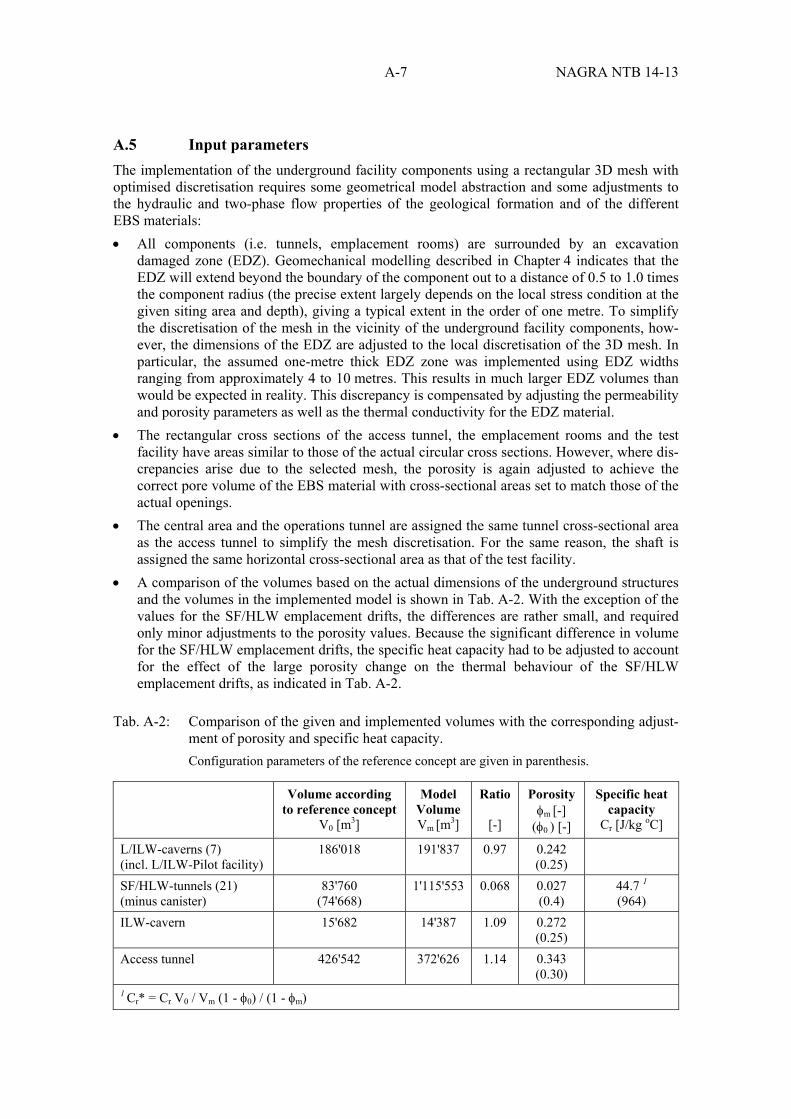
A-7 NAGRA NTB 14-13
A.5 Input parameters
The implementation of the underground facility components using a rectangular 3D mesh with optimised discretisation requires some geometrical model abstraction and some adjustments to the hydraulic and two-phase flow properties of the geological formation and of the different EBS materials: All components (i.e. tunnels, emplacement rooms) are surrounded by an excavation
damaged zone (EDZ). Geomechanical modelling described in Chapter 4 indicates that the EDZ will extend beyond the boundary of the component out to a distance of 0.5 to 1.0 times the component radius (the precise extent largely depends on the local stress condition at the given siting area and depth), giving a typical extent in the order of one metre. To simplify the discretisation of the mesh in the vicinity of the underground facility components, how-ever, the dimensions of the EDZ are adjusted to the local discretisation of the 3D mesh. In particular, the assumed one-metre thick EDZ zone was implemented using EDZ widths ranging from approximately 4 to 10 metres. This results in much larger EDZ volumes than would be expected in reality. This discrepancy is compensated by adjusting the permeability and porosity parameters as well as the thermal conductivity for the EDZ material.
The rectangular cross sections of the access tunnel, the emplacement rooms and the test facility have areas similar to those of the actual circular cross sections. However, where dis-crepancies arise due to the selected mesh, the porosity is again adjusted to achieve the correct pore volume of the EBS material with cross-sectional areas set to match those of the actual openings.
The central area and the operations tunnel are assigned the same tunnel cross-sectional area as the access tunnel to simplify the mesh discretisation. For the same reason, the shaft is assigned the same horizontal cross-sectional area as that of the test facility.
A comparison of the volumes based on the actual dimensions of the underground structures and the volumes in the implemented model is shown in Tab. A-2. With the exception of the values for the SF/HLW emplacement drifts, the differences are rather small, and required only minor adjustments to the porosity values. Because the significant difference in volume for the SF/HLW emplacement drifts, the specific heat capacity had to be adjusted to account for the effect of the large porosity change on the thermal behaviour of the SF/HLW emplacement drifts, as indicated in Tab. A-2.
Tab. A-2: Comparison of the given and implemented volumes with the corresponding adjust-ment of porosity and specific heat capacity. Configuration parameters of the reference concept are given in parenthesis.
Volume according to reference concept
V0 [m3]
Model Volume Vm [m3]
Ratio
[-]
Porosity m [-]
(0 ) [-]
Specific heat capacity
Cr [J/kg oC]
L/ILW-caverns (7) (incl. L/ILW-Pilot facility)
186'018 191'837 0.97 0.242 (0.25)
SF/HLW-tunnels (21) (minus canister)
83'760 (74'668)
1'115'553 0.068 0.027 (0.4)
44.7 1
(964) ILW-cavern 15'682 14'387 1.09 0.272
(0.25)
Access tunnel 426'542 372'626 1.14 0.343 (0.30)
1 Cr* = Cr V0 / Vm (1 - 0) / (1 - m)
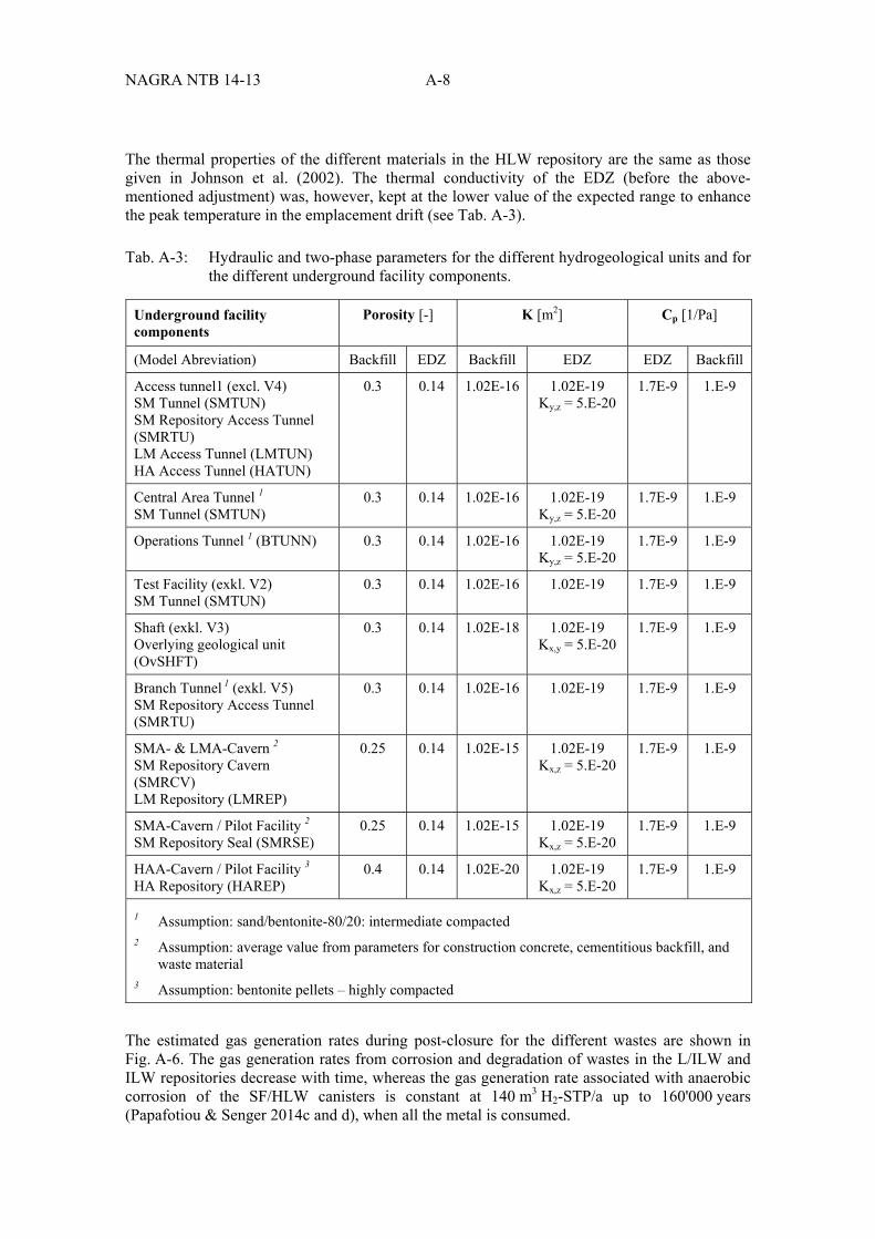
NAGRA NTB 14-13 A-8
The thermal properties of the different materials in the HLW repository are the same as those given in Johnson et al. (2002). The thermal conductivity of the EDZ (before the above-mentioned adjustment) was, however, kept at the lower value of the expected range to enhance the peak temperature in the emplacement drift (see Tab. A-3).
Tab. A-3: Hydraulic and two-phase parameters for the different hydrogeological units and for the different underground facility components.
Underground facility components
Porosity [-] K [m2] Cp [1/Pa]
(Model Abreviation) Backfill EDZ Backfill EDZ EDZ Backfill
Access tunnel1 (excl. V4) SM Tunnel (SMTUN) SM Repository Access Tunnel (SMRTU) LM Access Tunnel (LMTUN) HA Access Tunnel (HATUN)
0.3 0.14 1.02E-16 1.02E-19 Ky,z = 5.E-20
1.7E-9 1.E-9
Central Area Tunnel 1 SM Tunnel (SMTUN)
0.3 0.14 1.02E-16 1.02E-19 Ky,z = 5.E-20
1.7E-9 1.E-9
Operations Tunnel 1 (BTUNN) 0.3 0.14 1.02E-16 1.02E-19 Ky,z = 5.E-20
1.7E-9 1.E-9
Test Facility (exkl. V2) SM Tunnel (SMTUN)
0.3 0.14 1.02E-16 1.02E-19 1.7E-9 1.E-9
Shaft (exkl. V3) Overlying geological unit (OvSHFT)
0.3 0.14 1.02E-18 1.02E-19 Kx,y = 5.E-20
1.7E-9 1.E-9
Branch Tunnel 1 (exkl. V5) SM Repository Access Tunnel (SMRTU)
0.3 0.14 1.02E-16 1.02E-19 1.7E-9 1.E-9
SMA- & LMA-Cavern 2 SM Repository Cavern (SMRCV) LM Repository (LMREP)
0.25 0.14 1.02E-15 1.02E-19 Kx,z = 5.E-20
1.7E-9 1.E-9
SMA-Cavern / Pilot Facility 2 SM Repository Seal (SMRSE)
0.25 0.14 1.02E-15 1.02E-19 Kx,z = 5.E-20
1.7E-9 1.E-9
HAA-Cavern / Pilot Facility 3 HA Repository (HAREP)
0.4 0.14 1.02E-20 1.02E-19 Kx,z = 5.E-20
1.7E-9 1.E-9
1 Assumption: sand/bentonite-80/20: intermediate compacted 2 Assumption: average value from parameters for construction concrete, cementitious backfill, and
waste material 3 Assumption: bentonite pellets – highly compacted
The estimated gas generation rates during post-closure for the different wastes are shown in Fig. A-6. The gas generation rates from corrosion and degradation of wastes in the L/ILW and ILW repositories decrease with time, whereas the gas generation rate associated with anaerobic corrosion of the SF/HLW canisters is constant at 140 m3 H2-STP/a up to 160'000 years (Papafotiou & Senger 2014c and d), when all the metal is consumed.
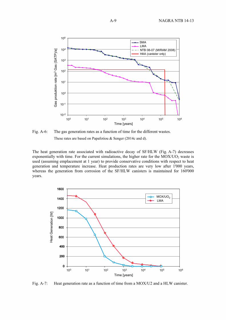
A-9 NAGRA NTB 14-13
Fig. A-6: The gas generation rates as a function of time for the different wastes. These rates are based on Papafotiou & Senger (2014c and d).
The heat generation rate associated with radioactive decay of SF/HLW (Fig. A-7) decreases exponentially with time. For the current simulations, the higher rate for the MOX/UO2 waste is used (assuming emplacement at 1 year) to provide conservative conditions with respect to heat generation and temperature increase. Heat production rates are very low after 1'000 years, whereas the generation from corrosion of the SF/HLW canisters is maintained for 160'000 years.
Fig. A-7: Heat generation rate as a function of time from a MOX/U2 and a HLW canister.
105
104
103
102
101
100
101100 102 103 104 105 106
10-1
10-2
Time [years]
Gas
pro
dukt
ion
rate
[m3
Gas
(SA
TP)/a
]
SMALMANTB 08-07 (MIRAM 2008)HAA (canister only)
200
0
400
600
800
1000
1200
1400
1600
200
0
400
600
800
1000
1200
1400
1600
Hea
t Gen
erat
ion
[W]
200
0
400
600
800
1000
1200
1400
1600
MOX/UO2LMA
101100 102 103 104 105 106
Time [years]

NAGRA NTB 14-13 A-10
A.6 Initial and boundary conditions and evolutionary phases
Initially, ambient conditions for the pressure within the model domain are hydrostatic, based on the approximate elevation of the local drainage elevation of 415 m asl across the model area (Tab. A-1). The initial temperature distribution is based on an assumed linear gradient of 0.042 ºC/m, and a prescribed temperature of 15 ºC at the top boundary. This corresponds approximately to the regional geothermal gradient in the area and yielded the expected ambient temperatures at repository depth. For the non-isothermal simulations, the temperatures at the top and bottom boundary are held constant.
The following phases in the evolution of the repository systems are modelled:
Phase 1: Excavation, construction and testing phase of the L/ILW repository region: open caverns for 20 years – ventilation assumed to take place.
Phase 2: Backfilling of L/ILW caverns and start of resaturation; excavation of the tunnels for the SF/HLW/ILW facility over a period of 20 years.
Phase 3: Closure of SF/HLW/ILW emplacement rooms; shafts kept open for monitoring for a further 30 years.
Post-closure phase (after 30 years of monitoring): start of gas generation in the waste emplacement rooms and heat generation in the SF/HLW emplacement drifts.
Initially, atmospheric pressure is assumed in the open underground facility, and the effect of ventilation was accounted for, to a first approximation, by setting the capillary suction pressure for the different EBS components to the initial emplacement saturation of the respective backfill materials. Closure of the different underground facility components is represented by allowing the initial pressure to recover.
A.7 Model results
The different mechanisms whereby pressure in the different parts of the co-disposal repository builds up are examined in separate simulations, each using the same initial conditions and the same sequence of phases for construction, operation and closure. The simulations comprise:
Case 1: Resaturation of the repository emplacement rooms and tunnels during and after the operational phase without any gas or heat generation.
Case 2: Post-closure phase considering only gas generation in the L/ILW and SF/HLW/ILW emplacement rooms.
Case 3: Post-closure phase considering only heat generation in the SF/HLW emplacement rooms (i.e., no gas generation from the L/ILW, SF/HLW and ILW).
Case 4: Post-closure phase considering both heat generation from SF/HLW and gas generation from L/ILW, SF/HLW and ILW. The results of each cases are shown in terms of pressure build-up in the different parts of the co-disposal repository, and also the spatial distribution of pressure, gas saturation and (where heat generation is simulated) temperature.
Operational phase simulation
The simulation of the operational phase (only carried out for Case 1, above) in fact covers the first three evolutionary phases described above, up to the time of repository closure at the end of Phase 3 (after 70 years). The pressure distributions at this time in the repository horizon and in a

A-11 NAGRA NTB 14-13
vertical plane are shown in Figs. A-7 and A-8; the saturation distribution is shown in Fig. A-9. Since heat generation is not modelled, the temperature distribution remains simply the ambient temperature distribution in the rock, and so is not illustrated.
The pressure responses in the different parts of the repository reflect the sequential opening of the different repository rooms and tunnels, and indicate very little recovery following closure of the L/ILW and ILW caverns and of the SF/HLW emplacement drifts (Fig. A-8). The pressure distribution along a vertical section through the L/ILW cavern (Fig. A-9) illustrates how hydro-static conditions are maintained within the bulk of the rock, with depressurisation confined to the underground facilities.
Fig. A-8: Pressure distribution in the repository horizon at the end of Phase 3 (70 years).
Pg (Pa)1.0E+075.0E+061.0E+06
0
0
-1000
1000
-1000 1000
-2000
-2000
-3000
X (m)
Y (m
)

NAGRA NTB 14-13 A-12
Fig. A-9: Pressure distribution in the vertical section through the L/ILW cavern (at X coordi-nate = 510 m) at the end of Phase 3 (70 years).
Fig. A-10: Gas saturation distribution in the plane of the repository horizon at the end of the Operational Phase 3 (70 years).
Pg (Pa)1.0E+075.0E+061.0E+06
200
0
0
400
-1000
-200
-2000-3000Y (m)
Z (m
)
Sg1.0E-04 1.0E-02 1.0E+00
0
0
-1000
1000
-1000 1000
-2000
-2000
-3000
X (m)
Y (m
)

A-13 NAGRA NTB 14-13
The saturation distribution at the end of the operational phase (Fig. A-10) reflects largely the gas saturation of the backfill material at emplacement, except in the case of the SF/HLW emplacement drifts, where a significant increase in water saturation from an initial value of 10 % to about 45 % takes place during the 30-year monitoring period following closure of the drifts.
Post-closure simulations
The results of the simulation cases examining the different mechanisms for pressure build-up following closure are summarised in Fig. A-11. The first three simulation cases consider indivi-dually the effects of (1) resaturation, (2) gas generation, and (3) heat generation. The fourth simulation case combines the heat and gas generation in the SF/HLW emplacement drifts and gas generation in the ILW and L/ILW caverns.
Fig. A-11: Pressure histories in the repository components during the operational and post-closure phases for the simulation cases 1 to 4: (a) Case 1: resaturation without heat and gas generation, (b) Case 2: gas generation, (c) Case 3: heat generation, and (d) case 4: combined resaturation, heat- and gas generation.
ILWL/ILWSF/HLWRep. Seal (V4)HLW+7 mHLW+25 m
ILWL/ILWSF/HLWRep. Seal (V4)HLW+7 mHLW+25 m
ILWL/ILWSF/HLWRep. Seal (V4)HLW+7 mHLW+25 m
ILWL/ILWSF/HLWRep. Seal (V4)HLW+7 mHLW+25 m
1.0E+00
1.0E+07
8.0E+06
6.0E+06
4.0E+06
2.0E+06
0.0E+001.0E+02 1.0E+04 1.0E+06
Time (years)a) b)
c) d)
Pre
ssur
e (P
a)
1.0E+00
1.0E+07
8.0E+06
6.0E+06
4.0E+06
2.0E+06
0.0E+001.0E+02 1.0E+04 1.0E+06
Time (years)
Pre
ssur
e (P
a)
1.0E+00
1.0E+07
8.0E+06
6.0E+06
4.0E+06
2.0E+06
0.0E+001.0E+02 1.0E+04 1.0E+06
Time (years)
Pre
ssur
e (P
a)
1.0E+00
1.0E+07
8.0E+06
6.0E+06
4.0E+06
2.0E+06
0.0E+001.0E+02 1.0E+04 1.0E+06
Time (years)
Pre
ssur
e (P
a)
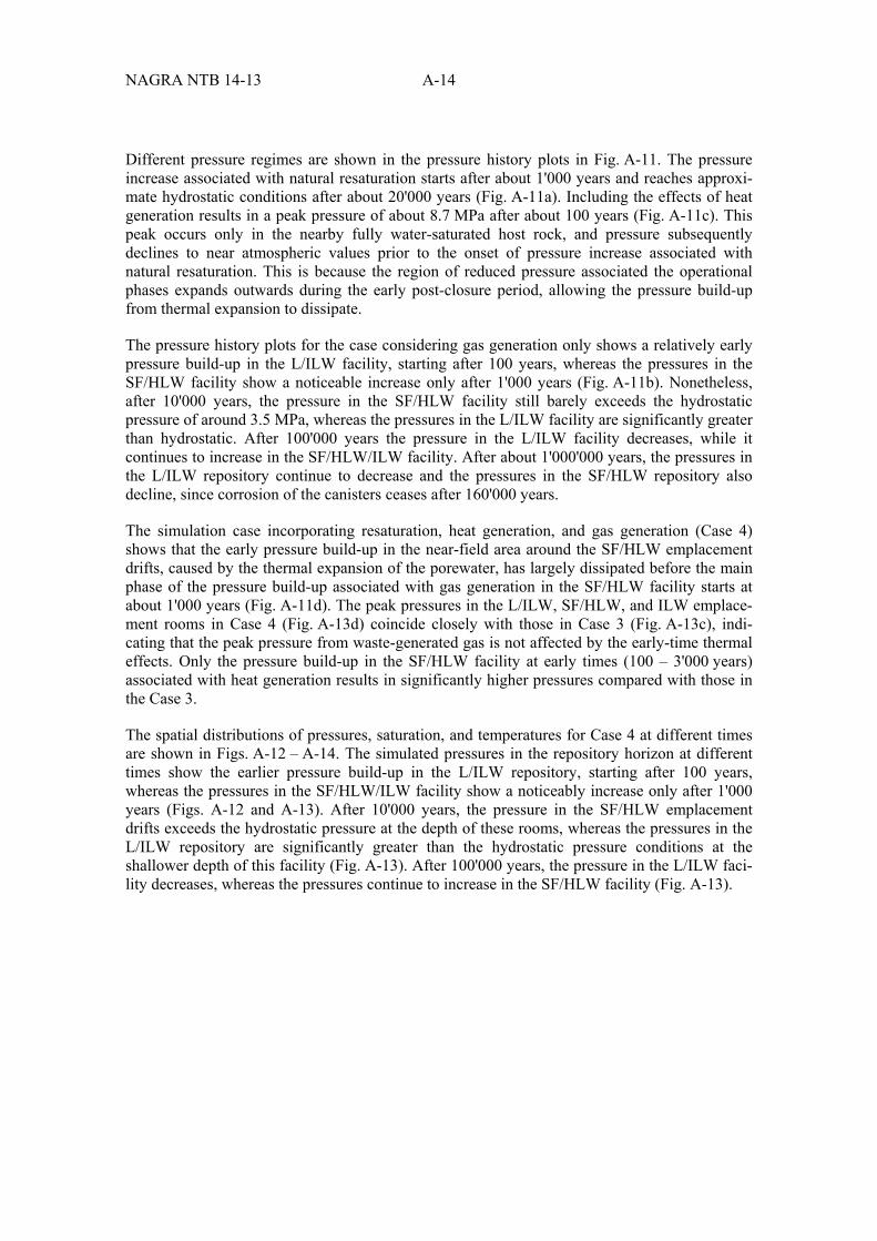
NAGRA NTB 14-13 A-14
Different pressure regimes are shown in the pressure history plots in Fig. A-11. The pressure increase associated with natural resaturation starts after about 1'000 years and reaches approxi-mate hydrostatic conditions after about 20'000 years (Fig. A-11a). Including the effects of heat generation results in a peak pressure of about 8.7 MPa after about 100 years (Fig. A-11c). This peak occurs only in the nearby fully water-saturated host rock, and pressure subsequently declines to near atmospheric values prior to the onset of pressure increase associated with natural resaturation. This is because the region of reduced pressure associated the operational phases expands outwards during the early post-closure period, allowing the pressure build-up from thermal expansion to dissipate.
The pressure history plots for the case considering gas generation only shows a relatively early pressure build-up in the L/ILW facility, starting after 100 years, whereas the pressures in the SF/HLW facility show a noticeable increase only after 1'000 years (Fig. A-11b). Nonetheless, after 10'000 years, the pressure in the SF/HLW facility still barely exceeds the hydrostatic pressure of around 3.5 MPa, whereas the pressures in the L/ILW facility are significantly greater than hydrostatic. After 100'000 years the pressure in the L/ILW facility decreases, while it continues to increase in the SF/HLW/ILW facility. After about 1'000'000 years, the pressures in the L/ILW repository continue to decrease and the pressures in the SF/HLW repository also decline, since corrosion of the canisters ceases after 160'000 years.
The simulation case incorporating resaturation, heat generation, and gas generation (Case 4) shows that the early pressure build-up in the near-field area around the SF/HLW emplacement drifts, caused by the thermal expansion of the porewater, has largely dissipated before the main phase of the pressure build-up associated with gas generation in the SF/HLW facility starts at about 1'000 years (Fig. A-11d). The peak pressures in the L/ILW, SF/HLW, and ILW emplace-ment rooms in Case 4 (Fig. A-13d) coincide closely with those in Case 3 (Fig. A-13c), indi-cating that the peak pressure from waste-generated gas is not affected by the early-time thermal effects. Only the pressure build-up in the SF/HLW facility at early times (100 – 3'000 years) associated with heat generation results in significantly higher pressures compared with those in the Case 3.
The spatial distributions of pressures, saturation, and temperatures for Case 4 at different times are shown in Figs. A-12 – A-14. The simulated pressures in the repository horizon at different times show the earlier pressure build-up in the L/ILW repository, starting after 100 years, whereas the pressures in the SF/HLW/ILW facility show a noticeably increase only after 1'000 years (Figs. A-12 and A-13). After 10'000 years, the pressure in the SF/HLW emplacement drifts exceeds the hydrostatic pressure at the depth of these rooms, whereas the pressures in the L/ILW repository are significantly greater than the hydrostatic pressure conditions at the shallower depth of this facility (Fig. A-13). After 100'000 years, the pressure in the L/ILW faci-lity decreases, whereas the pressures continue to increase in the SF/HLW facility (Fig. A-13).
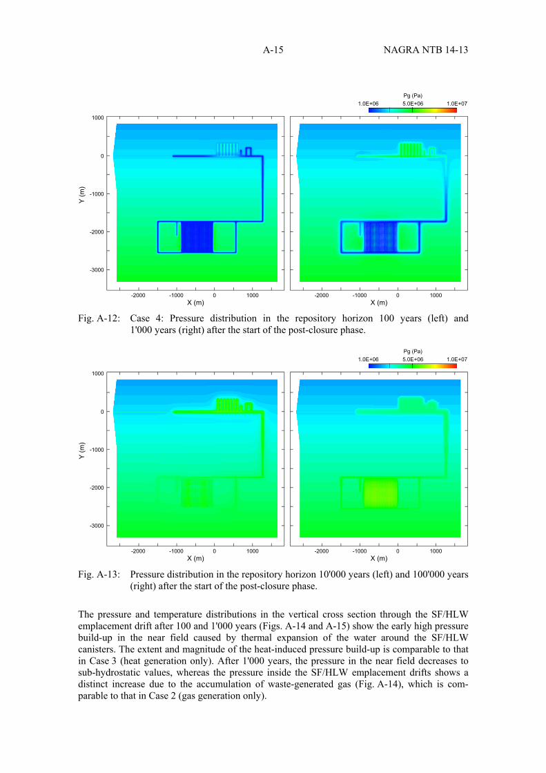
A-15 NAGRA NTB 14-13
Fig. A-12: Case 4: Pressure distribution in the repository horizon 100 years (left) and
1'000 years (right) after the start of the post-closure phase.
Fig. A-13: Pressure distribution in the repository horizon 10'000 years (left) and 100'000 years (right) after the start of the post-closure phase.
The pressure and temperature distributions in the vertical cross section through the SF/HLW emplacement drift after 100 and 1'000 years (Figs. A-14 and A-15) show the early high pressure build-up in the near field caused by thermal expansion of the water around the SF/HLW canisters. The extent and magnitude of the heat-induced pressure build-up is comparable to that in Case 3 (heat generation only). After 1'000 years, the pressure in the near field decreases to sub-hydrostatic values, whereas the pressure inside the SF/HLW emplacement drifts shows a distinct increase due to the accumulation of waste-generated gas (Fig. A-14), which is com-parable to that in Case 2 (gas generation only).
Pg (Pa)1.0E+075.0E+061.0E+06
0
0
-1000
1000
-1000 1000
-2000
-2000
-3000
X (m)
Y (m
)
0-1000 1000-2000X (m)
Pg (Pa)1.0E+075.0E+061.0E+06
0
0
-1000
1000
-1000 1000
-2000
-2000
-3000
X (m)
Y (m
)
0-1000 1000-2000X (m)

NAGRA NTB 14-13 A-16
Fig. A-14: Case 4: Pressure distribution in a vertical section through a SF/HLW emplacement drift 100 years (left) and 1'000 years (right) after the start of the post-closure phase.
Pg (Pa)1.0E+075.0E+061.0E+06
200
0
0
400
-1000
-200
-2000-3000Y (m)
Z (m
)
200
0
0
400
-1000
-200
-2000-3000Y (m)
Z (m
)

A-17 NAGRA NTB 14-13
Fig. A-15: Case 4: Temperature distribution 100 years (above) and 1'000 years (below) after the start of the post-closure phase in a vertical section through a SF/HLW emplace-ment drift.
T (degC)20 40 60 80 100
200
0
0
400
-1000
-200
-2000-3000Y (m)
Z (m
)
200
0
0
400
-1000
-200
-2000-3000Y (m)
Z (m
)

NAGRA NTB 14-13 A-18
A.8 Discussion and conclusions
A numerical study of the two-phase flow behaviour for a combined L/ILW and SF/HLW/ILW repository in Opalinus Clay has been carried out to examine effects on pressure evolution associated with (a) resaturation of backfilled underground facilities, (b) heat generation from radioactive decay of radionuclides in SF/HLW, and (c) gas generation due to corrosion and degradation of different waste components. The operational phases of each repository compo-nent have been simulated, the results of which provide initial conditions for the post-closure phase, which are the same for all simulation cases.
The simulations indicate that the resaturation and pressurisation of the backfilled underground facilities require thousands of years; pressures start to recover after about 1'000 years and reach hydrostatic conditions after about 20'000 years.
Within the first tens to hundreds of years, heat generated by radioactive decay in the SF/HLW canisters causes thermal expansion of porewater, leading to a pressure build-up mainly in the fully water-saturated host rock around the emplacement drifts. In the emplacement drifts them-selves, which are initially only partly saturated, the pressure build-up is much smaller due to the high compressibility of air. A peak pressure of about 8.7 MPa is reached in the near field after about 100 years, followed subsequently by a rapid decline as the rate of heat generation decreases exponentially and excess pressures are dissipated in an expanding region of the rock around the emplacement drifts.
Later, a more significant pressurisation mechanism affecting both the backfilled repository structures and the surrounding host rock is gas generation. The gas generation rates from the corrosion and degradation of wastes in the L/ILW and ILW emplacement caverns are assumed to decrease with time (Nagra 2008d); the L/ILW gas generation rate is more than one order of magnitude greater than that from the ILW. The ILW emplacement caverns are near the SF/HLW drifts, but are a greater distance away from the L/ILW facility. The gas generation rate associated with anaerobic corrosion of the SF/HLW canisters is initially at a much lower rate than that from L/ILW and ILW, but its contribution to the total rate becomes larger over time, since it is assumed to remain constant until all the metal is corroded at 160'000 years. As a result, the pressure build-up due to L/ILW gas generation occurs earlier, and the pressure build-up from the SF/HLW repository starts later. The simulated pressure build-up in the L/ILW facility starts after the onset of the post-closure phase and is characterised by a near linear increase between 10 and 4'000 years, when a peak pressure of 6.5 MPa is reached. This is followed by gradual decreases to near hydrostatic pressures after 1 million years.
The pressure build-up in the ILW facility is more gradual at early times compared with that due to L/ILW. At later times, the pressures in the ILW emplacement cavern largely follow the pres-sures in the SF/HLW repository. The SF/HLW facility undergoes an early pressure rise between 100 and 1'000 years due to thermal effects, followed by a steep increase between 3'000 and 10'000 years and a continuing increase to a maximum pressure of 6.5 MPa after 160'000 years. This is the time when all the metal is corroded and the gas generation stops, resulting in a sudden decline, before the pressure levels off at about 4.5 MPa in the SF/HLW emplacement drifts after a million years.
The pressure histories show a distinct separation in the pressure peak of the L/ILW facility and those of the SF/HLW/ILW repository. Moreover, thermal phenomena only affect the pressures in SF/HLW at early times (prior to about 2'000 years). The simulations show that gas migrates from the L/ILW emplacement caverns into the access tunnel, the additional length of which compared with a repository for L/ILW provides additional storage for gas accumulation (see

A-19 NAGRA NTB 14-13
Fig. A-11). Only after the pressures in the L/ILW caverns start to decline, does the pressure in the SF/HLW drifts exceed that in the L/ILW facility, resulting in gas migration from the SF/HLW facility through the tunnels toward the repository seal.
Based on this modelling study, it appears that the pressure regimes in the L/ILW and SF/HLW/ILW facilities evolve rather independently. Only the pressures in the ILW part show some interference from the other waste forms, being affected by the pressure build-up in the nearby SF/HLW emplacement drifts. The results suggest that a horizontal separation distance of a few hundred metres between the L/ILW facility and the SF/HLW/ILW facility is sufficient to avoid interference in the pressure build-up in these two parts of a combined repository.