Embed Size (px)
Citation preview

Technical Report No. 97-6
A Regime Stream Channel Reclamation Approach for Placer-Mined Watersheds
Alaska Department of Fish and Game Habitat and Restoration Division
Janet Kowalski, Director
Provisional Draft - Subject to Agency & Coastal District Review December 1997

Stream Channel Design Software
The Alaska Department of Fish and Game administers all programs and activities free from discrimination on the basis of sex, color, race, religion, national origin, age, marital status, pregnancy, parenthood, or disability. For in formation on alternative formats available for this and other department publications contact the department ADA Coordinator (voice) 90 7/465-4120: (TTD) 90 77'4 78-3648. Any person who believes s h e has been discriminated against should write to: ADF& G, PO Box 25526, Juneau, AK 99802-5526 or O.E.O. U.S. Department of the Interior, Washington D. C. 20240.

A Regime Stream Channel Reclamation Approach for Placer-Mined Watersheds
By:
Robert F. "Mac" McLean
Alaska Department of Fish and Game Habitat and Restoration Division
Janet Kowalski, Director
Provisional Draft - Subject to Agency & Coastal District Review December 1997

Acknowledgements
This project was partially funded by a federal Office of Ocean and Coastal Resource Management (OCRM) Section 309 grant totalling $146,000 provided to the Alaska Department of Fish and Game through the Alaska Division of Governmental Coordination for establishment of an Aquatic Habitat Restoration Working Group. Approximately $40,000 of the federal grant was expended on development of these interim stream reclamation guidelines. Specific activities included: literature review, agency coordination, field "truthing" design equations, development of the Microsoft ~ x c e l ~ ~ spreadsheets, and report preparation.
The principle author is Robert F. "Mac" McLean. Initial technical review of the Microsoft ~xcel"'" spreadsheets containing the channel design formulas was provided by Steve McGroarty and Jim Vohden, Alaska Department of Natural Resources, Division of Mining and Water Management, and Marlene Braun, U. S. Bureau of Land Management.
Questions regarding the interim guidelines or the scope and purpose of the grant project should be directed to Mr. McLean at:
Tel.: 9071459-728 1 FAX: 9071456-3091 E-mail: [email protected]
Special thanks is given to Mr. Hugh McNairney, RRl Site 19B, Compartment 14, Enderby, B.C., ZOE 1ZO for permission to use the cover art work (originally published in Toews and Browlee, 198 1).
RPT 97-6 Dec - 97

Table Of Contents Paae
. . Acknowledgements ........... .... .. ... .. .. .. .. ..... .. ..... .. ......... .. .......... .. .. .. .. ..... .. .. ........... .............................. 11
. . . Table of Contents ........................................................................................................................... ni
List of Tables ................................................................................................................................. iv
List of Figures ................................................................................................................................ iv
Introduction. .. . . . . . . . . . . . . . . . . . . . . . . . . . . . . . . . . . . . . . . . . . . . . . . . . . . . . . . . . . . . . . . . . . . . . . . .. .. . . . . . . . . . . . . . . . . . . . . . . . . . . . .. . . . . . . . . . . . . . . . . . . . . . . . . . . . .1
Channel Stability - Maintaining Dynamic Equilibrium ................................................................... 2
Stream Channel Reclamation Methodologies .................................................................................. 5
Stream Channel Reclamation Worksheets ....................................................................................... 6
General Channel Diversion Design Considerations ........ .. .. ........... ................ .. .... .. ............ ....... ....... 7
Acceptable Risk Factors for Stream Diversion Channels ................................................................ 8
Estimating Design Discharge .... .. .. . .. .. .. .. .......... .. .. .. .. ... .. , .. .. ................ ............. ...... .. ....... ..... ....... ... ... 9
Permanent Stream Channel Hydrologic Design Frequency ............................................................ 9
General Construction and Best Management Practices (BMPs) . .. .. . . . . . . . . . . . . . . . . . . . . . . . . . . . . . . . . . . . . . . . . . . . . . . l o
Glossary of Terms .......................................................................................................................... 11
Literature Cited . .. .... .. ..... .. .. .. .. ..... .. .. .. .. ... .. .. ..... .. .. ....... .. ... ....... .. .. .. .. .. ... .. .. ......... ...... ................... ..... 14
APPENDIX &gg
A. Example ~ i c r o s o f t ~ x c e l ~ ~ Channel Design Worksheet .................................................. 17
B. General Stream Channel Reclamation Considerations ...................................................... 29
C. Classification of Channel Types .... ... .. ......... .. .. .... .. .. .. .. .. .. .. . . . . ......... . . . . . . 3 1
PLATES (Plates are in back pocket)
1. Map showing locations og gaging stations and crest-stage partial record sites having at least 8 years of peak-flow data, and mean minimum January temperature for Alaska and conterminous basins of Canada. (From: Jones and Fahl, 1994).
2. Map showing mean annual precipitation for Alaska and conterminous basins of Canada. (From: Jones and Fahl, 1994).
RPT 97-6 Dec - 97

List of Tables Pag-e
................................................... Table 1 . Acceptable risks of flooding for stream diversions. 8 Table 2. Flood frequency recurrence interval (years) corresponding to
........................................................................ acceptable risk factors and project life 8 Table 3. Design stream channel flood frequency and risk of failure
within ten years. ........................................................................................................ 10
List of Figures
Figure 1. Stable channel balance. (Sediment load times sediment size) varies as (stream slope times stream discharge. From Lane (1955).
Figure 2. Slope-discharge relationship for braiding or meandering in sandbar streams. From Lane (1 957).
RPT 97-6 Dec - 97

Make it hard to do fyou want to discourage an action -
But make it easy to do i f you want to encourage a particular practice.
Introduction
The above axiom is the primary motivation for development of these interim stream channel restoration guidelines and associated computer spreadsheets. While fluvial morphologists have gained considerable understanding over the past century regarding geologic, hydrologic, and hydraulic factors affecting stream morphology, applying this knowledge to the day-to-day reality of state and federal regulatory agency approvals of placer mining operations in Alaska is complicated by limited staffing, absence of site- specific information, and limited exposure of many regulators to hydrogeomorphic principals.
Over the years, numerous regulators have expressed desire for consistent, straight- forward, science-based, stream channel reclamation guidelines. In response to this need, ADF&G contracted with Entrix, Inc. in 1986 to produce the two-volume report "Best Management Practices for Placer Mining" (Rundquist, et. al., 1986). While technically this report did an excellent job pulling together the basic engineering principals needed for successful stream channel reclamation, it required extensive pre-mining field surveys and detailed mathematical calculations to develop a reclamation plan. Most miners and regulators found it confusing and beyond their fiscal or technical capabilities. In 1989 a multi-agency group of state and federal regulators assembled a working group in Fairbanks charged with developing a consistent channel reclamation design methodology. This effort also failed to achieve desired results largely because agencies were unable to commit the resources necessary to prepare site-specific reclamation designs.
In light of this history, development of consensus stream reclamation guidelines was identified as one of the highest priority work tasks at the January 26, 1996 organizational meeting of the Alaska Working Group on Aquatic Habitat Restoration. This Working Group was established under an Alaska Division of Governmental Coordination Section 309 grant from the federal Office of Coastal Resource Management as an experimental, inter-agency team charged with identifying practicable solutions for day to day permitting and technical constraints limiting effective aquatic habitat conservation and restoration. Pivotal to the groups endorsement was a recognition that stream channel reclamation guidelines would need to be "relatively painless" for state and federal regulators to implement. Regulators and coastal district participants requested not only clear guidelines but a largely automated, computerized design methodology that would take much of the guess-work out plan approval, yet provide a science-based design that would provide at least nominal levels of protection for aquatic resources and riparian communities.
RPT 97-6 Dec - 97

After nearly two years of meetings with state, federal, local agencies, coastal districts, private industry, and other interested stakeholders, part of which was dove-tailed with the Department of Environmental Conservation's Section 3 19-funded placer mine reclamation program, Microsoft ~ x c e l ~ ~ spreadsheets and supporting design guidelines were developed using regional hydrologic regressions and channel regime equations to simplify the process of calculating stream flow estimates and stable channel morphology. The spreadsheets are structured to generate a regime stream channel design that approximates the median morphologies within the range of naturally occurring channel dimensions and morphologies.
A complete design can be prepared directly from a USGS 1 :63,360 Series Quad map with as few as eight input variables or enhanced with inclusion of site-specific field data when available. Typical time commitment for each plan is less than 15 minutes.
The interim design guidelines and worksheets are not intended as substitutes for traditional hydraulic designs by professional civil or mining engineers. Rather, they are intended for use when either professionally engineered designs are not required by law (as is the case under the Alaska Mining Reclamation Act - AS 27.19) or agency permitting timelines do not allow permit decisions to be delayed until adequate field studies can be conducted. Simply stated, the design worksheets are intended as a reality check that provides a median approximation of what a reclaimed stream channel should look like. Stream channel designs developed with the simplified methods should always be followed-up with on-the-ground reality checks and post-permitting site inspections. All permits approved using these methods should include a standard condition that allows for future modification of the channel design if subsequent field investigations indicate modifications are warranted.
Disclaimer: These stream channel design guidelines and microcomputer worksheets are provided as a public service to assist the mining industry, state and federal regulators, and coastal districts with evaluating stream channel reclamation plans. They do not constitute ADF&G official guidelines, policies, or regulatory requirements.
Channel Stability - Maintaining Dynamic Equilibrium
Geomorphological theory provides general information regarding the direction and extent of long-term channel stability but generally does not provide numbers useful for exact design. Nevertheless, a knowledge of geomorphology is very important for selecting a more exact hydraulic analysis method (Keefer, et. al., 1980).
Qualitative geomorphic analysis of channel stability is based on the concept of dynamic equilibrium. Rivers strive, in the long run, to achieve a balance between the product of water flow and channel slope and the product of sediment discharge and size. The most widely known geomorphic relation embodying the dynamic equilibrium concept is known as Lane's principle (Lane, 1955). More comprehensive assessment of channel response to changing conditions were conducted by Leopold and Maddock (1953), Scl~umm (1971), Santos-Cayudo and Simons (1972), and Rechard and Hasfwther (1980).
RPT 97-6 2 Dec - 97

Collectively, this research supports the following generalities regarding dynamic equilibrium (Keefer, et. al., 1980). Figure 1 depicts these relationships graphically.
depth of flow is directly proportional to water discharge and inversely proportional to sediment discharge; width of channel is directly proportional to water discharge and to sediment discharge; shape of channel expressed as width-depth ratio is directly related to sediment discharge; meander wavelength is directly proportional to water discharge and to sediment discharge; slope of the stream channel is inversely proportional to water discharge and directly proportional to sediment discharge and grain size; and sinuosity of the stream channel is proportional to valley slope and inversely proportional to sediment discharge.
These relations define the general response of any water conveying channel to change. Mathematically, these general relationships are expressed by the Sixth Power Law as:
the velocity offlowing water is doubled: the erosive,force increases four times;
the potential sediment transport increases 32 times; the diameter oj'a particle moved increases four times; and
the muss of the particle moved increases 64 times.
(STREAM SLOFE)x(STREAM DISCHARGE)
RPT 97-6
Figure 1. Stable channel balance. (Sediment loads times sediment size) varies as (stream slope times stream discharge). From Lane (1 955).
Dec - 97

The concept of dynamic equilibrium is useful in evaluating stream systems and selecting the appropriate reclamation strategy. The concept does not imply that absolute equilibrium conditions exist, but that streams can adjust to new conditions within a given range of stability. Heede (1975) lists several factors indicative of small mountain streams not in dynamic equilibrium:
channel headcuts; under developed drainage nets such as those having channelized water courses only on one-half or less of the watershed area; frequent bedscarps; and the absence of a concave longitudinal profile.
Channel headcuts are local erosion sources because headcuts advance upstream. They indicate that the stream length and gradient are not in equilibrium with the substrate size and water velocity. Bedscarps similarly indicate pronounced breaks in longitudinal gradients. These scarps proceed upstream until a smooth transition between upstream and downstream gradient is obtained. Channelized, straightened water courses often are an end product of mine reclamation. If decreased channel length results in a channel slope outside of the continuum of equilibrium values, significant changes in channel sinuosity, slope, and channel pattern may develop. Small increases in channel slope can shift a stream channel out of the equilibrium zone for a meandering channel pattern into a braided channel configuration (Figure 2).
INTERMEDIATE
W ~ ~ * I I S I P I . . ,
0 ( 2 %
MEANDENING 9.2 0 .owe. ,..#NO#S STREAM
Figure 2. Slope-discharge relationship for braiding or meandering in sandbar streams. From Lane (1957).
RPT 97-6 4

Stream Channel Reclamation Methodologies
Fluvial morphologists have identified several approaches for restoring hydraulic balance to reclaimed stream beds. Hasfurther (1985) summarizes these as follows:
4 carbon copy: the stream channel is reconstructed exactly to its pre-disturbance width, depth, slope and meander morphology. While the technique has merit in some instances, it is based on several key assumptions that frequently are not applicable. First, it presumes that the pre-disturbance channel is stable. Second, it presumes that other factors such as bedload transport rates, substrate and bank materials, runoff rates, and riparian vegetation remain constant. In reality, the hydrogeomorphology of placer mined watersheds rarely, if ever, remains constant pre- and post-mining. Substrate size gradation, riparian vegetation, and permafrost generally are radically altered and completely change the controls affecting channel development.
4 empirical relationships: morphological relationships are developed for specific regions and/or sub-regions and applied to the affected site. Although extrapolation of these equations to other watersheds potentially can be misleading, this technique is firmly founded on field investigations and often may be the only viable approach if site-specific data is unavailable.
4 natural approach: a valley is created with the reclaimed material with the intent that natural processes will take over and form their own stream channel and drainage basin morphology. Disequilibriums associated with this approach can cause high rates of erosion and sediment movement and can take decades to centuries to reach equilibrium.
4 systems approach: includes meander analysis and an evaluation of the geomorphology of the disturbed area and its effect on surrounding undisturbed areas. This method is site-specific and generally preferable but is data intensive and generally not feasible for regulators in all instance due to limited staffs and the present need to review and issue necessary permits prior to when field investigations could be completed.
As noted, while the systems approach is the preferred methodology, it requires a large amount of pre- and post-disturbance field data. In many instances, regulators are not able to collect the necessary information and model it before permit decisions are required. Permit applicant's may be unwilling to forgo operations for a year or two to acquire the necessary data. Politically, state and federal reclamation laws presently do not explicitly require channel reclamation under the systems approach methodology. Managers thus may feel pressured to accept a less rigorous design methodology. The Microsoft ~ x c e l ~ ~ worksl~eets presented here are constructed using the second preferred methodology, or empirical relationship approach.
RPT 97-6

Stream Channel Reclamation Worksheets
Nine Microsoft ~ x c e l ~ " files were developed for the following hydrogeographic areas.
Southeast Alaska and Prince William Sound (FILE: se-ak.xls) Cook Inlet 1 Mantanuska Valley (FILE: cook-inl.xls) Anchorage Bowl (FILE: anch.xls) Copper River Valley (FILE: copper.xls) Kodiak Island, South-side Alaska Peninsula and Aleutians Islands (FILE: kodiak.xls) Bristol Bay (FILE: bristol.xls) Southwest Alaska - Kuskokwim River (FILE: sw-ak.xls) Western, Northwestern, and Arctic Alaska (FILE: western.xls) Interior 1 Central Yukon River (FILE: yukon.xls)
The worksheets require the input of basic background project information (name, location, fish species, etc.) and the following eight variables:
drainage area in square miles (digitized from a USGS 1:63,360 series quad map); percent forest cover (digitized from the green area depicted on a USGS 1 :63,360 series quad map); percent lake storage (digitized from the lake area depicted on a USGS 1:63,360 series quad map); mean minimum January temperature in OF. From Jones and Fahl(1994) - Plate 1); mean annual precipitation in inches. From Jones and Fahl(1994) - Plate 2); mean watershed elevation in feet; down valley slope in feetlfeet (digitized from 1 :63,360 series USGS quad map; and maximum channel velocity (from Table 1 in the worksheet based on channel substrate size).
Based on these input variables, the worksheets automatically calculate the bankfull, two year, five year, 10 year, 20 year, 25 year, and 50 year flood discharges. Six separate regional regression models are included to provide an internal cross-check on the hydrology estimates. The average summer flow also is calculated to provide a reality check that users can compare to stream flows they may have observed during the open water months.
The worksheet includes data input cells for on-site field observations. If this data is available, the worksheets will override the regime equation-generated bankfull width and depth calculations and substitute actual channel measurements in the floodplain and channel meander calculations. If site-specific data is available on stream substrate armor and subpavement D50 gravel size, the worksheets will calculate the critical and design shear stress (1bs.lft.) for the proposed stream channel.
Determining a stable bank full channel width and depth is the next automatic calculation. Eight separate regime calculations for gravel-bed rivers are presented for an internal
RPT 97-6

cross-check and comparison. The worksheets next determines the appropriate post- mining channel type based on the down valley gradient and the bankfull discharge.
The next sequence is the automatic calculation of temporary and permanent channel dimensions. Two options are presented for temporary diversions: (1) for unstable, non- cohesive soils in wide floodplains, and (2) for stable, cohesive soils in narrow valleys. Using an acceptable risk analysis approach, different channel dimension are calculated depending on the length of time the stream diversion will remain in use and the relative fisheries values of the stream. Permanent channel and flood plain dimensions (both reclamation of an existing channel or a permanent channel diversion) are calculated for both high gradient-mountain streams and lower gradient-meandering channels.
Channel reclamation design summaries are generated including plan view and cross- sectional profiles of the regime-generated channel. Recommended channel widths, depths, flood plain widths, meander wavelength, meander beltwidth, and radius of curvature are included. The worksheets automatically run through two iterations to calculate the necessary channel sinuosity if the initial proposed channel slope is greater than the equilibrium slope for the substrate material available.
Finally, the worksheets contains input cells to automatically calculate the relationship of various channel features to each other when only one or more values are known.
The final table in the worksheet provides users with an abbreviated management interpretation of the sensitivity of various stream channel types to disturbance, long-term recovery, sediment supply, bank erosion potential, and the importance of riparian vegetation to maintaining channel stability.
An example worksheet for Western Alaska is presented in Appendix A.
General Channel Diversion Design Considerations
At mining sites located within an active floodplain, the stream channel may need to be diverted to minimize water flow through the excavation area. The diversion should be sited, designed, constructed, and operated to avoid excessive erosion or deposition, to contain floods within the range of acceptable risks, and to meet fish passage requirements if fish are present.
The location of the diversion channel should be identified during the planning phase and will depend on site features, equipment available to construct the diversion channel, the proposed sequence of mining operations, and the acceptable risk of flooding. In a narrow valley, the channel diversion may be routed along the valley walls or along one side of the floodplain. At sites where mining cuts as wide as the entire floodplain are not necessary, a permanent stream channel can be constructed on the previously mined portion of the floodplain prior to mining the other portion. This reduces the reclamation effort and minimizes impacts to fish and wildlife.
RPT 97-6

The actual design of a temporary diversion channel involves the interaction of hydrology, hydraulic engineering, and geotechnical engineering. This interaction can be complex, and miners may be well advised to seek engineering assistance. However, the Microsoft ~ x c e l ~ " worksheets represent a simplified approach suitable for most Alaska placer mining operations. Additional information may be obtained in the Surface Mining Water Diversion Design Manual (Simons, Li and Associates, 1982) and Best Management Practicesfor Placer Mining (Entrix, Inc., 1986).
Diversion channels should be designed for valley reaches of relatively constant slope. If the diversion channel is placed along the valley wall, the upstream and downstream ends of the channel will likely have different slopes and will require separate designs. Transitions between the sections should be gradual.
Acceptable Risk Factors For Stream Diversion Channels
Diversion channels must be sized to carry anticipated streamflows during the period they will be in operation without excessive erosion or overtopping. The flood frequency probability can be used to evaluate the consequences and risks associated with the design life of the diversion channel (Tables 1 and 2). These risk factors are built into the Microsoft ~ x c e l ~ ~ worksheets.
Table 1. Acceptable Risks of Flooding for Stream Diversions.
Fisheries Value of Stream Structure High Medium Low Diversion Channel 20% 35% 5 0% Settling Ponds 5% 10% 20% Stockpiles 5% 10% 20% Hazardous Material and Camp 6 % <5% <5%
Table 2. Flood Frequency Recurrence Interval (Years) Corresponding to Acceptable Risk and Project Life.
Project Acceptable Risk (%) +Life 5 10 15 20 25 30 35 40 45 50 60
1 20 10 7 5 4 3 3 2 2 2 1.7 2 40 19 13 9 7 6 5 4 4 3 3 3 59 29 19 14 11 9 7 6 6 5 4 4 78 38 25 18 14 12 10 8 7 6 5 5 98 48 31 23 18 15 12 10 9 8 6
10 195 95 62 45 35 29 24 20 17 15 11
RPT 97-6 Dec - 97

Estimating Design Discharge
The order of preference for calculating flood flows is:
1. Log Pearson I11 analysis as defined in Water Resources Council Bulletin 17B, 198 1, "Guidelines for Determining Flood Flow Frequencies" should be used for all routine designs where sufficient stream gauging records exist.
2. Local (watershed specific) regression equations where available.
3. USGS 1993 regional regression equations calibrated to nearby gauged data.
4. USGS 1993 regional regression equations un-calibrated.
5. US Army Corps of Engineers HEC-1 Flood Hydrograph if it can be calibrated and verified with actual rainfall and runoff data. This method is data intensive.
6. NRCS (formerly SCS) and other unit hydrograph methods.
7. Rational method for drainage areas less than 200 acres (only if all other methods are inappropriate).
All regional regressions and other flood discharge estimation techniques have significant standard errors associated with them (20 to 50%).
IN ALL CASES, flood discharge estimates should be cross-checked against observed field conditions in an undisturbed section of the stream. When uncertainties exist, it is usually best to return the restored channel to its original, undisturbed bankfull dimensions.
Permanent Stream Channel Hydrologic Design Frequency
Permanent stream channels should be sized to accommodate a bankfull discharge. Typically, a bankfull discharge corresponds to a flood frequency of 1 .O to 2.5 years (1.5 years - best estimate) (Leopold, 1994). (Caution: some investigators working in the inter-mounlain states suggest that bankfull discharges in smaller headwater drainages located in arid regions more closely correspond to a 5 yearJloodJFequency).
The flood design frequency should be selected commensurate with the magnitude and risk associated with damages from larger flood events. Potential risks include ecological site recovery as well as potential property damage, legal and political requirements and economic costs. Floodplains should be sized to accommodate the following flood design frequencies unless otherwise dictated by site conditions.
RPT 97-6 Dec - 97

Table 3. Design Stream Channel Flood Frequency and Risk of Failure Within 10 Years.
Acceptable Risk of Channel Failure
Flood Plain Risk of Failure Category Design Frequency Within 10 Years
Non-fish Stream 15 yr. 5 0% Low Value Fish Stream 20 yr. 40% Moderate Value Fish Stream 25 yr. 34% High Value Fish Stream 50 yr. 18%
General Construction and Best Management Practices (BMPs) The following guidelines are typical BMPs for construction of temporary channel diversions. These BMPs are intended to minimize fish stranding and non-point sedimentation during construction.
1. During excavation, the diversion channel must be isolated from the stream to be diverted at both the upstream and downstream ends of the diversion channel.
2. The bed and banks of the diversion channel must be constructed of material that will not erode at expected flows. For most diversion channels constructed of coarse tailings, the maximum water velocity should not exceed four feet per second.
3. Diversion of flow into the diversion channel must be conducted by first removing the downstream plug, then removing the upstream plug, then closing the upstream end and then the downstream end of the natural channel. Fish that become stranded in dewatered channels must be immediately captured and returned to the wetted channel without further harm.
5 . Stream diversion side slopes should not be steeper than two foot horizontal to one foot vertical (2: 1). Three foot horizontal to one foot vertical are preferred and will decrease the potential for bank erosion or failure.
6. Fish passage in the temporary bypass channel must be maintained at all times, unless otherwise directed by ADF&G.
Reclamation of Temporary Stream Diversions
Final reclamation of temporary stream diversions must conform to the overall final mine site reclamation plan, but should include provisions for backfilling and contouring the diversion channel. Valley wall diversion channels may be reclaimed by grading the diversion structure into a backsloping terrace.
Rediversion of temporary stream diversion flow into the natural or reconstructed channel must be conducted by removing the downstream plug from the natural channel and then the upstream plug, then closing the upstream end and then the downstream end of the diversion channel. Fish that become stranded in dewatered channels must be immediately captured and returned to the wetted channel without further harm.
RPT 97-6 Dec - 97

Glossary of Terms
Aggradation - A progressive buildup or raising of the channel bed and floodplain due to sediment deposition. The geologic process by which stream beds are raised in elevation and floodplains are formed. Aggradation is an indicator that a change in the stream's discharge and/or bedload characteristics is taking place. Opposite of degradation.
Armoring - A natural process where an erosion-resistant layer of relatively large particles is established on the surface of the streambed through removal of finer particles by stream flow. A properly armored streambed generally resist movement of bed material at discharges up to approximately 314 bankfull depth.
Avu1,sion - A change in channel course that occurs when a stream suddenly breaks through its banks - typically bisecting an over extended meander arc.
Bunkjull Discharge - The stream discharge corresponding to the water stage which first overtops the natural banks. This flow occurs , on average, about once ever 1 to 2 years (1.5 years).
Bunkfull Channel Depth - The maximum depth of a channel within a riffle segment when flowing at a bankfull discharge.
Bankfull Channel Width - The top surface width of a stream channel when flowing at a bankfull discharge.
Bed Load - Sediment moving on or near the stream bed and transported by jumping, rolling, or sliding on the bed layer of a stream. See also suspended load.
Bed Roughness - A measure of the irregularity of the stream bed as it contributes to flow resistance. Commonly expressed as a Manning "n" value.
Bed Slope - The inclination of the channel bottom.
Braided Channel - A stream characterized by flow within several channels which successively meet and divide. Braiding often occurs when sediment loading is too large to be carried by a single channel.
C'r~itical Shear Stress - The minimum amount of shear stress exerted by stream currents required to initiate soil particle motion. Because gravity also contributes to stream bank particle movement but not on stream beds, critical shear stress along streambanks is approximately 25% less than for stream beds.
Degradation - A progressive lowering of the channel bed due to scour. Degradation is an indicator that that a change in the stream's discharge and/or sediment load is occurring. The opposite of aggradation.
RPT 97-6 Dec - 97

Drainage Area - The total surface area upstream of a point on a stream that drains toward that point. Not to be confused with watershed. The drainage area may include one or more watersheds.
Energy Dissipation - The loss of kinetic energy of moving water due to internal turbulence, bottom friction, large rocks, debris, or other obstacles that impede flow.
Floodplain - a strip of relatively smooth land bordering a stream, built of sediment carried by the stream, which overflows at discharge stages greater than bankfull.
Fluvial - Pertaining to streams or produced by stream action.
Geomorphology - A branch of both physiography and geology that deals with the form of the earth, the general configuration of its surface, and the changes that take place due to erosion of the primary elements and in the buildup of erosional debris.
Hydraulic Gradient - The slope of the water surface. See also stream bed gradient.
Hydraulic Radius - The cross-sectional area of a stream divided by the wetted perimeter.
Hydrograph - A curve showing stream discharge over time.
Mean Annual Discharge - Daily mean discharge averaged over a period of years. Mean annual discharge generally fills a channel to about 113 of its bankfull depth.
Mean Velocity - The average cross-sectional velocity of water in a stream channel. Surface values typically are much higher that bottom velocities. May be approximated in the field by multiplying the surface velocity, as determined with a float, times 0.8.
Meander - The winding of a stream channel, usually in an erodible alluvial valley. A series of sine-generated curves characterized by curved flow and alternating banks and shoals.
Meander Amplitude - The distance between points of maximum curvature of successive meanders of opposite phase in a direction normal to the general course of the meander belt, measured between centerlines of channels.
Meander Lenglh - The lineal distance down valley between two corresponding points of successive meanders of the same phase.
Meander Belt Width - the distance between lines drawn tangential to the extreme limits of fully developed meanders. Not to be confused with meander amplitude.
Morphology - The form or shape of a stream, including the contours of its bottom.
Point Bar - The convex side of a meander bend that is built up due to sediment deposition.
RPT 97-6 12 Dec - 97

Prohuhility of Exceedence - The probability that a random flood will exceed a specified magnitude in a given period of time.
Regime - A theory of channel formation that applies to streams that make a part of their boundaries from their transported sediment load and a portion of their transported sediment load from their boundaries. Channels are considered in regime or equilibrium when bank erosion and bank formation are equal.
S'cour - Erosion due to flowing water; usually considered localized as opposed to general bed degradation.
Sinuosity - The ratio of channel length to direct down valley distance. Also may be expressed as the ratio of down valley slope to channel slope.
Stable Channel - A stream channel is considered stable, or in dynamic equilibrium, when it establishes the right balance of bed slope and cross-section to transport both the water and upstream sediment load without net bed or bank sediment deposition or erosion throughout the stream segment.
Suspended Sediment Load - That portion of a stream's total sediment load which is transported within the body of water and has very little contact the stream bed.
Tractive Force - The drag on a streambank caused by passing water which tends to pull soil particles along with the streamflow.
RPT 97-6 Dec - 97

Literature Cited
ADF&G. 1986. Alaska habitat management guide - guidelines for the protection of fish and their habitat. Alaska Department of Fish and Game, Habitat and Restoration Division. Anchorage, AK.
Ashton, W.S. and Carlson, R.F. 1984. Determination of seasonal, frequency, and durational aspects of streamflow with regard to fish passage through roadway drainage structures. AK. Department of Transportation and Public Facilities. Rpt. NO. FHWA-AK-RD-85-06. 5 1 p.
Bray, D.I. 1982. Requime equations for gravel-bed rivers. In: Gravel-Bed Rivers, Ed. by R.D. Hey, J.C. Bathurst, and C.R. Thorne. John Wiley and Sons, Ltd. pp. 517- 542.
Beschta, R.L. 1992. Channel characteristics and hydrology of Birch Creek, Interior Alaska. Oregon State University. 37 p.
Carlson, R.F. 1987. Seasonal frequency and duration aspects of streamflow in Southeast and Coastal Alaska. AK. Department of Transportation and Public Facilities. Rpt. NO. FHWA-AK-RD-97-22. 40 p.
Chang, H.H.. 1985. River morphology and thresholds. Journal of Hydraulic Engineering. American Society of Civil Engineers.Vo1. 11 1:3. pp. 503-519.
Chang, Howard H. (1988) Fluvial Processes in River Engineering. Wiley, New York.
Chow, V.T. 1959. Open-channel hydraulics. McGraw-Hill Book Company
Drage, B. and Carlson, R.F. 1977. Hydraulic geometry relationships for northern braided rivers. In: Proceedings of Third National Hydrotechnical Conference, Quebec, 30-3 1 May. pp. 235-251.
Emmett, W.W. 1972. The hydraulic geometry of some Alaskan streams south of the Yukon River. U.S. Geological Survey. Open File Rpt. 102 p.
Hardy BBT, Ltd. 1991 (Third Edition). Guidelines for the design and construction of stream channels for Yukon placer mined streams. Prepared for the Department of Fisheries and Oceans Canada, Habitat Management Division.
Hasfurther, V.R. 1985. The use of meander parameters in restoring hydrologic balance to reclaimed stream beds. IN: The Restoration of Rivers and Streams, Ed. J.A. Gore. Butterworths, Boston, MA. pp. 2 1-40.
RPT 97-6 Dec - 97

Heede, Burchard. 1975. Mountain watersheds and dynamic equilibrium. In: Watershed Management Syposium, American Society of Civil Engineers, Logan, UT. pp. 407- 419.
Hey, R.D. 1982. Design equations for mobile gravel-bed rivers. In: Gravel-Bed Rivers, Ed. by R.D. Hey, J.C. Bathurst, and C.R. Thorne. John Wiley and Sons, Ltd. pp. 553-574.
Hey, R. 1983. Plan geometry of river meanders. In: River Meandering, Proc. of the Conference River '83, New Orleans, 24-26 October. C.M. Elliott, Ed. American Society of Civil Engineers. pp. 30-43.
Jones, Stanley H. and Fahl, Charles B. 1994. Magnitude and frequency of floods in Alaska and conterminous basins of Canada. U.S. Geological Survey, Water Resources Investigations Rpt. 93 -4 179. Anchorage, AK.
Kane, D.L. and Janowicz, J.R. 1989. Flood frequency estimation for Alaska. AK Department of Natural Resources, Division of Geological Survey. Rpt. 88-17. 22 p.
Keefer, T.N., McQuivey, R. S., and Simons, D.B. 1980. Channel degradation and aggradation: causes and consequences to highways. Interim Report. Prepared for the Federal Highway Administration. Report No. FHWAIRD-801038.86 p.
Lacey, Gerald. 1948. A general theory of flow in alluvium. Jour. Institute Civil Engineers, Paper 55 15, Vol. 27.
Lamke, R.D. 1979. Characteristics of Alaskan Streams. US Geological Survey. Water Resources Investigations 78- 129. 66 p.
Lane, E. W. 1955. The importance of fluvial morphology in hydraulic engineering. American Society of Civil Engineers Proceedings, Hydraulic Division, 81 :745-1 to 745-17.
Lane, E.W. 1957. A study of the shape of channels formed by natural streams flowing in erodible material. MRD Sediment Series No. 9, U.S. Army Engineers, Omaha, NE.
Leopold, Luna B. 1994. A view of the river. Harvard University. 298 p.
Leopold, Luna B. and Maddock, Thomas. 1953. The hydraulic geometry of stream channels and some physiographic implications. U.S. Geological Survey Professional Paper 252. 57 p.
Neill, C.R. 1973. Guide to bridge hydraulics. University of Toronto Press. 191 p.
Rechard, R.P. and V.R. Hasfurther. 1980. The use of meander parameters in the restoration of mined stream beds in the eastern Powder River basin. Laramie, WY Rocky Mtn. Inst. Energy and Environ., Univ. of Wyoming.
RPT 97-6 15 Dec - 97

Rosgen, D. 1994. A classification of natural rivers. Catena, Vol. 22: 169-1 99.
Rundquist, L.A., Bradley, N.E., Baldridge, J.E., Hampton, P.D., Jennings, T.R., and Joyce, M.R. 1986. Best Management Practices for Placer Mining, Reference Manual and Technical Report. Entrix, Inc. for the AK Department of Fish and Game.
Saiitos-Cayudo, J. and Simons, D.B. 1973. River response. In: Environmental Impact of Rivers, edited by H.W. Shen. Fort Collins, CO. Water Resource Publ.
Schumm. S.A. 197 1. Fluvial geomorphology-the historical perspective. In River Mechanics, edited by H.W. Shen. Fort Collins, CO. Water Resource Publ.
Simmons, Li and Associates. 1982. Surface mining water diversion design manual. Prepared for the U.S. Dept. of the Interior Office of Surface Mining.
Toews, D.A.A. and Browlee, M.J. 1981. A handbook for fish habitat protection on forest lands in British Columbia. Department of Fisheries and Oceans Canada, Habitat Protection Division. Vancouver, B.C. 166 p.
Williams, Garnett P. 1986. River meanders and channel size. Journal of Hydrology, Vol. 88:147-164.
RPT 97-6 Dec - 97

APPENDIX A
Sample Microsoft ~ x c e l ~ ~ Channel Design Spreadsheet
Nine Microsoft ~xcel'" files are included in the accompanying diskette for the following geographic areas.
1. Southeast Alaska and Prince William Sound (FILE: se-ak.xls)
2. Cook Inlet / Mantanuska Valley (FILE: cook-inl.xls)
3. Anchorage Bowl (FILE: anch.xls)
4. Copper River Valley (FILE: copper.xls)
5 . Kodiak Island, South-side Alaska Peninsula and Aleutians Islands (FILE: kodiak.xls)
6. Bristol Bay (FILE: bristol.xls)
7. Southwest Alaska - Kuskokwim River (FILE: sw-ak.xls)
8. Western, Northwestern, and Arctic Alaska (FILE: western.xls)
9. Interior / Central Yukon River (FILE: yukon.xls)
The files are saved in Version 5.0 (Windows 3.3 1 for Workgroups) and are upwardly compatible with newer desktop systems, including Microsoft Office 95 and 97.
The files are compressed for distribution using the pkzip.exe utility. Individual worksheets may be uncompressed for use on an I B M ~ ~ compatible microcomputer hard drive by running the pkunzipexe utility included with this diskette.
To uncompress a file,
first create a target sub-directory on your hard drive, then insert the diskette into your floppy drive (normally A:\), log over to your A:\ drive, and type the following command at the A:\ prompt:
PKUNZIP A:\(selected file).zip C:\(target sub-directory)
Example: PKUNZIP A:\western.zip C:\channel
A sample spreadsheet for the western Alaska sub-region follows.
Dec - 97

RPT 97-6
(Leave Blank)
18 Dec - 97

ALASKA DEPARTMENT OF FISH AND GAME (McLean, 1997, ADF&G-H&RD Technical Report 97-6)
$ PROJECT SITE: Doe, John 2 USGS Quad: Nome C-2
Waterbody: Unnamed Creek Fish Resource Values: AG, Coho, Dolly varden
ADF&G #: 98-XXX APMA #: F98XXXX
' REGIONAL REGRESSION PEAK DISCHARGE ESTIMATES: (Formulas for Western, Northwest, and North Slope Alaska, USGS Area 3) The 1993 USGS Regressions (Jones and Fahl, 1993) are considered the most reliable for instantaneous high flows.
+ \D
Max. Channel Vel. (from
**Note: If correction factors are available for similar, adjacent gaged watersheds - use them to adjust Jones and Fahl regression values and input under "Gaged Flows."
FIELD OBSERVATIONS Rosgen Channel Type =
Bankfull Width (ft.) = feet Bankfull Depth (ft.) = feet
Meander Wavelength = feet
Valley Floor Width = feet
Channel Slope = 0.015 ft./ft. Watershed Aspect = 0
0
a -4 Armor Layer (d50) = 3 inches (est.)
Subpavement (D50) = 1.5 inches (est.)
Ratio (d501D50 = 2
PRELIMINARY HYDRAULIC CALCULATIONS NOTES / EQUATIONS Hydraulic Radius (Rh)@Qbf = 0.92 Hydraulic radius approx. = depth if W/D Ratio > 10
(Se) Equilibrium Slope = 0.0246 @where Se=0.08*d50/0.75*(Rh)
Is Equilibrium Slope > Valley Slope? YES CALC. Design Shear Stress = 0.0229 @where T = (Depth*So)/(~,/~,)-l)*d50
[Depth in (m); Y, = spec. weight of sediment; Y, =
spec. weight of water; d50=med. diam. armor layer in (m)]
MAX Critical Bed Shear Stress = 0.045568832 @where T, = 0.0834*(d50/D50)A-0.872
MAX Critical Bank Shear Stress = 0.0342 @where T,,,,, = 75% T,
Is Design Stress < Critical (Bed)? YES @Applies to moderately straight channels on mild slopes;
Is Design Stress < Critical (Bank)? YES decrease by 10% for slightly sinuous; 25% for moderate.
c:\channel\western.xIs Page 1 Dec-97

CALCULATED TYPE "C" MEANDER AND BRAIDED BANKFULL CHANNEL MORPHOLOGY (does not include constructed floodplain)
InvestigatorlMethod FORMULA (Ft.lLbs. Units) OUTPUT Correlation (8) Bray (1982) W=2.38*Q2/\.53 BF Top Width (ft.) = 21.22 0.962
d=0.226*Q2".33 Bankfull Depth (ft.) = 0.88 0.871 V=1,58*Q2". 14 Av. Vel. (fps) = 2.82 0.499
Emmett (1 972) W=2.39*QbfA.5 BF Top Width (ft.) = 14.58 (Alaskan Meander Streams) d=.26*QbfA.35 Bankfull Depth (ft.) = 0.92
V=l .62*QbfA. 15 Av. Vel. (fps) = 2.79
Drage & Carlson (1 977) W=4.66*QbfA.47 BF Top Width (ft.) = 25.51 0.54 (Braided Streams) d=. 1 3*QbfA.38 Bankfull Depth (ft.) = 0.51 0.63
V=l .65*QbfA. 15 Av. Vel. (fps) = 2.84 0.29
General Hydraulic Model ~ = a ~ 2 ~ BF Top Width (ft.) = 27.65 Beschta (1 992) d = c ~ 2 ' Bankfull Depth (ft.) = 0.70 Q=discharge AVERAGE VALUES: b=0.5; f=0.4 W=channel width a and c are back calculated from observed flows and channel widths in d=mean depth upper Birch Ck.; a=3.51; c=0.134).
USGS Channel Width W=(Q2/.4)"1 I1 .82 BF Top Width (ft.) = 15.99 D=O. 12WA0.69 Bankfull Depth (ft.) = 0.81 (USGS NIA; Used Williams (1 986) WID Relationship)
Lacey (1 948) W=2.67QbfA.5 BF Top Width (ft.) = 16.29 D=(Qbfl(l 3.5*((D,,*25.4)"0.5)))A0.333 Bankfull Depth (ft.) = 0.68
Yukon Placer 1990 DFO WID W=2.73*QbfA0.5 BF Top Width (ft.) = 16.66 Charts (converted from metric) D=0.22*QbfA0.333 Bankfull Depth (ft.) = 0.73
Chang (1988) W=[l .905+0.249(1n(0.0001065*D,oA1 .15)l(S*QbfA0.42))]*QbfA0.47 BF Top Width (ft.) = 11.34 - Sc - So D=[0.2077-0.0418(ln(0.000442*D5,"1.15)l(S*QbfA0.42))]*QbfAO.42 Bankfull Depth (ft.) = 0.91 0.0120 0.015
Is So > Sc? YES
TABLE 1. Max. Channel Velocities ( f p ~ ) ( ~ i m o n s , Li &Assoc., 1982; Neill, 1973;Chow, 1959)
@ to & Average Sandy Soil 1.5 to 1.8 Average Loam or Alluvial Soil 1.9 to 2.2
TABLE 2. Mannings (n) (Rundquist, et. al. 1986)
Minimum Averaae Maximum 0.018 0.02 0.022 0.018 0.02 0.022
' Stiff Clay I Ordinary Gravel Q
3.0 to 3.6 0.022 0.025 0.03 " l~oa rse Gravel or Cobble 3.5 to 4.3 Typical 0.03 0.04 0.05
Boulders ( I ft.) 7.5 to 9.0 0.04 0.05 0.06 Boulders (2 ft.) I Bedrock 10.0 to 12.0 0.05 0.06 0.07
c:\channel\western.xIs Page 2
TABLE 3. Stream Sinuosity vs. Slope.
Sinuosity vs. Slope (adapted from Rosgen, 1994, classification scheme)
Channel Slope (%)
Selection of Stream Type (modified from Bray, 1982)
10% T-.---
1 Meander -- \I Type "c'-
S~ Q, Discharge (cfs)
Stream Type Slope (%) Sinuosity (K) Aa+ 10 1
1 TABLE 4. Selection of Stream Type.
Q2 (X) Slope (Y) Y=0.2*XA -0.44 (R2=0.99)
10 7% 100 2.50%
1000 0.95% 10000 0.34% 100000 0.001 2
PRELIMINARY ROSGEN CLASSIFICATION CALC. Stream Type (Bray, 1982)
(SV = 0.2 * ~ 2 " -0.44) Meandering CALC. Mannings (n) (Rosgen, 1994)
Page 3

TEMPORARY BYPASSES (OPTION 1) (Note: Channel dimensions sized for
icr Z; bankfull flow only; no adjacent floodplain is a provided to accomodate flood discharges. 2
This option is acceptable where the risk of overtopping is nominal and higher flood flows will not threaten settling ponds, camp, or stockpiled material.
TEMPORARY BYPASSES (OPTION 2) (Note: Trapezoidal channel with 2 : l side slopes. The channel is designed to fully contain the design discharge without overtopping.
w w
This option is best suited for narrow valleys where the footprint of the bypass needs to be minimized. Not suitable for unstable, non-cohesive soils due to higher probability of toe erosion and bank sloughing.
PERMANENT BYPASSES & CHANNELS
Note: Channel sized for bankfull flow (using Emmett equations) with adjacent floodplain benches extending from the bankfull edge. The floodplain shelf should grade back from the channel edge at no greater than the indicated slope.
0 , Floodplain shelf designed to accomodate 2 floods at 1.8 times bankfull depth (Q50).
Maintain original channel length to reduce stream power and channel erosion.
Page 4 Dec-97
Width and Depth of Temporary Bypass Channel (USGS Channel Width Equation) Duration Relative Fisheries Value:
Acceptable Risk of Failure:
1 Season Design Width (ft.) Design Depth (ft.)
1 Year Design Width (ft.) Design Depth (ft.)
2 Year Design Width (ft.) Design Depth (ft.)
LowINone 50%
Top Width & Depth of Temporary Bypass Channel (Rundquist et. al, 1986, BMP Manual)
Medium 35%
Duration Relative Fisheries Value: Acceptable Risk of Failure:
1 Season Design Top Width (ft.) Design Depth (ft.)
1 Year Design Top Width (ft.) Design Depth (ft.)
2 Year Design Top Width (ft.) Design Depth (ft.)
HJ~J 20%
3.64 0.29
LowINone 50%
4.77 0.35
Bankfull Channel Width and Depth and Width of Adjacent Floodplain (Emmett) Channel Tvpe
NOTES: Type "B" 2 to 4% Gradient Bankfull Width (ft.) 14.58 Use some judgement;
Entrenchment = I .4-2.2 Bankfull Depth (ft.) pq entrenchment ratio in Type (FloodproneIBankfull) Min. Floodplain (ft.) "B" streams varies from
Floodplain Slope (%) 25.29% 1.4 to 2.2. For Type "B" streams, the floodplain
6.25 0.42
15.99 0.81
Medium 35%
Type "C" Typically <2% Gradient Bankfull Width (ft.) Entrenchment =>2.2 Bankfull Depth (ft.) (Floodprone/Bankfull) Min. Floodplain (ft.)
Floodplain Slope (%)
ti^& 20%
19.78 0.94
4.85 0.81
-
15.90 2.65
2.96 0.49
14.58 0.92 17.50 4.22%
23.04 1.05
19.78 0.94
3.79 0.63
shelf extends along both banks. For Type "C" streams, the shelf runs along inside meanders.
13.83 2.31
23.04 1.05
1 1.40 1.90
27.44 1.18
13.83 2.31
15.90 2.65
18.64 3.11

Williams 1986 (Type INPUT 2nd CALC. "C" Meander Channels INPUT KNOWN KNOWN CALCULATED OUTPUT
7 Only) VARIABLE VARIABLE OUTPUT VARIABLE VALUE Standard Deviation Correlation (r)
Z; Interrelationships between meander features (formulas expressed in meters; inputloutput converted to feet for use in ft.llbs. units) 3 Lm = 1.25 Lb 0 Meander Wavelength = 0.00 32% -24% 0.99 k Lm= 1.63 B 0 Meander Wavelength = 0.00 31 % -24% 0.99
Lm = 4.53 Rc 0 Meander Wavelength = 0.00 21 % -1 7% 0.99 Lb = 0.80 Lm 0 Bend Length = 0.00 32% -24% 0.99 Lb = 1.29 B 0 Bend Length = 0.00 31 % -24% 0.99 Lb = 3.77 Rc 0 Bend Length = 0.00 35% -26% 0.98 B = 0.61 Lm 0 Meander Belt Width = 0.00 31 % -24% 0.99
B = 0.78 Lb 0 Meander Belt Width = 0.00 31 % -24% 0.99 B = 2.88 Rc 0 Meander Belt Width = 0.00 42% -29% 0.98 Rc = 0.22 Lm 0 Radius of Curvature = 0.00 21 % -1 7% 0.99 Rc = 0.26 Lb 0 Radius of Curvature = 0.00 35% -26% 0.98 Rc = 0.35 B 0 Radius of Curvature = 0.00 42% -29% 0.98
Relationship of channel size to meander features A = 0.0054*LmA1 .53 0
g A = 0.0085*LbA1 .53 0 A = 0.012*BA1 .53 0 A = 0.067 Rc 1.53 0 W = 0.1 7*LmA0.89 0 W = 0.23 Lb 0.89 0 W = 0.27*BA0.89 0 W = 0.71*RcA0.89 0 D = 0.027*LmA0.66 0 D = 0.036*LbA0.66 0 D = 0.037*BA0.66 0 D = 0.085*RcA0.66 0
Cross-sectional Area = Cross-sectional Area = Cross-sectional Area = Cross-sectional Area = Bankfull Width = Bankfull Width = Bankfull Width = Bankfull Width = Bankfull Mean Depth = Bankfull Mean Depth = Bankfull Mean Depth = Bankfull Mean Depth =
Relationship of meander features to channel size Lm = 30*AA0.65 0 Meander Wavelength = 0.00 59% -37% 0.96 Lb = 22*AA0.65 0 Channel Bend Length = 0.00 77% -43% 0.95 B = 18*AA0.65 0 Meander Belt Width = 0.00 56% -36% 0.97
0 I Rc = 5.8*AA0.65 0 Radius of Curvature = 0.00 76 % -43% 0.97 3 Lm = 7.5*WA1 . I 2 0 Meander Wavelength = 0.00 65% -39% 0.96
Lb = 5.1*WA1.12 0 Channel Bend Length = 0.00 65% -39% 0.97
c:\channel\western.xls Page 5

Williams 1986 (Type INPUT 2nd CALC. "C" Meander Channels INPUT KNOWN KNOWN CALCULATED OUTPUT
Only) VARIABLE VARIABLE OUTPUT VARIABLE VALUE Standard Deviation Correlation (r) % 4
Relationship of meander features to channel size (continued) 4
A B=4.3*WA1.12 0 Meander Belt Width = 0.00 74% -42% 0.96 Rc= 1.5*WA1.12 0 Radius of Curvature = 0.00 55% -35% 0.97 Lm = 240*DA1 ,512 0 Meander Wavelength = 0.00 142% -59% 0.86 Lb = 160*DA1 .52 0 Channel Bend Length = 0.00 128% -56% 0.90 B = 148*DA1 .52 0 Meander Belt Width = 0.00 115% -53% 0.90 Rc = 42*DA1 .52 0 Radius of Curvature = 0.00 165% -62% 0.90
Relationship between channel width, channel depth, and channel sinuosity W = 21 .3*DA1 .45 Bankfull Width = 0.00 160% -62% 0.81 D = 0.12*WA0.69 Bankfull Mean Depth = 0.00 94% -48% 0.81 W = 96*DA1 .23*KA-2.35 0 1 Bankfull Width = 0.00 121% -55% 0.87 D = 0.09*WA0.59*KA1 .46 0 1 Bankfull Mean Depth = 0.00 73% -42% 0.86
KEY A = Bankfull Cross-sectional Area Lm = Meander Wavelength Rc = Loop Radius of Curvature W = Bankfull Width Lb = Along-channel Bend Length K = Channel Sinuosity D = Bankfull Mean Depth B = Meander Belt Width
RULES OF THUMB (Meander Type "C" Channels) Q5 discharge is 1 . 2 ~ Qbf (bankfull) water surface elevation Meander Wavelength = 12 x Bankfull Width Q10 discharge is 1 . 4 ~ Qbf water surface elevation Meander Beltwidth = 6 x Bankfull Width Q50 discharge is 1 . 8 ~ Qbf water surface elevation = design floodplain height. Radius of Curvature = 2.3 x Bankfull Width Channel perturbations extend 5-10 channel widths downstream Decrease allowable velocities and tractive forces bv 13% and 25%.res~ectivelv, for moderatelv sinuous channels.
THE SIXTH POWER LAW If, the velocity of flowing water is doubled; the erosive force increases 4 times; the potential sediment transport increases 32 times; the diameter of a particle moved increases 4 times; and the mass of the particle moved increases 64 times.
Page 6

STREAM CHANNEL RECLAMATION DESIGN SUMMARY
Project Site: Doe, John USGS QUAD: Nome C-2 4 Waterbody: Unnamed Creek Existing Rosgen Stream Type: NIA 7 Permit No.: #REF! Constructed Rosgen Stream Type: TYPE C m
APMA: F98XXXX
CONSTRUCTED BANKFULL DIMENSIONS (plus) Standard Error (minus) Bankfull Discharge: 37 cfs Bankfull Top Width: 14.6 feet 22.8 9.3 Bankfull Bottom Width: 9.1 feet Design Bankfull Depth: 0.92 feet
Channel Design Vel.: 2.8 fps Est. Bank Vel. (Riffle): 1.9 fps Est. Sharp Bend Vel.: 3.7 fps
Total Floodplain Width: 32.1 feet (right limit to left limit) g Floodplain Shelf: 17.5 feet (extending along inside meander from bankfull channel edge)
Floodplain Backslope: 4.22% Maximum Slope Allowed. 50:l (2%) backslopes will minimize erosion Meander Length (Lm): 130.8 feet 216 80 Meander Beltwidth: 75.0 feet 131 44 Radius of Curvature: 26.2 feet
Down Valley Slope 1.50% Se Equilibrium Slope 2.46%
Design Shear Stress 0.0229 ~b . / f t .~ Critical Shear Stress
Bed 0.0456 ~b . / f t .~ Banks 0.0342 ~b . / f t .~
TYPICAL AVERAGE SUMMER DIMENSIONS Average Discharge: 6 cfs Top Width: 6.24 feet Bottom Width: 3.30 feet Depth: 0.49 feet
1st Iteration Design Channel Slope 1.02% 1st Iteration Design Channel Sinuosity 1.46
IS FIRST ITERATION SLOPE < EQUILIBRIUM? YES
2nd Iteration Design Channel Slope 1.02% 2nd Iteration Design Channel Sinuosity 1.46
u DISCLAIMER: Stream channel and floodplain morphology exhibit considerable variation. Regime equations and other empirical design (D o relationships are median approximations intended for use when (1) site-specific evaluations are not possible or (2) the I
w 4
geomorphology of the watershed has been completely altered and a different stream type is needed for stability.
Page 7

FIGURE 1. 2 m
h) m
FIGURE 2.
Typical Cross-Sectional Profile - Type "B" Step-Pool and "C" Meander Channels (Riffle Segment).
----- -- +- 14 6 b -- . '-,, \ --
/' m a ~ . 4.22% 9.1 +/ 15%
SUMMARY Top Width 14.6 ft.
Bottom Width 9.1 ft. Bankfull Depth 0.92 ft.
Floodprone Width (Q50) 32.1 ft. Bank Slope 15% 3 to1
Max. Floodplain Back Slope 4.22% 11 to1
Typical Cross-Sectional Profile - Pool Section - Type "C" Meander Channels.
- -- --- -_ _ _ _ 4 + _-_-- - - - - m a ~ . 4.22% , 1 m a ~ . 4.22%
28% 7.11%
SUMMARY Top Width 14.6 ft.
Inside Bank to Thalweg 11.7 ft. Thalweg located 20% of width out Bankfull Depth at Thalweg 1.84 ft. from cutbank
Flood prone Width (Q50) 32.1 ft. Max. Cut Bank Slope 28% 1.6 to I
Max. Inside Bank Slope 7.11% 6.3 to I Max. Floodplain Back Slope 4.22% 11 to1
Page 8

FIGURE 3. Typical Top Profile View - Type "C" Meander Channels.
4- - Meander Wavelength = 130.8 --
Pool b Pool
-- - -- - - , , ,
- ---- , - - - A \\ Rc= , 26 2
Riffle - Beltwidth Riiie = 75 0
\ -
, - -- v Pool
SUMMARY
Meander Wavelength
Meander Pathlength
Meander Beltwidth
Down Valley Slope
Channel Slope
Sinuosity
130.8 ft.
191.6 ft.
75.0 ft.
1.50%
1.02%
1.46
Qbankfull 37 C ~ S
Q2 62 cfs
Q5 121 cfs
QIO 166 cfs
Q 2 5 230 cfs
Q 5 o 276 cfs
Page 9
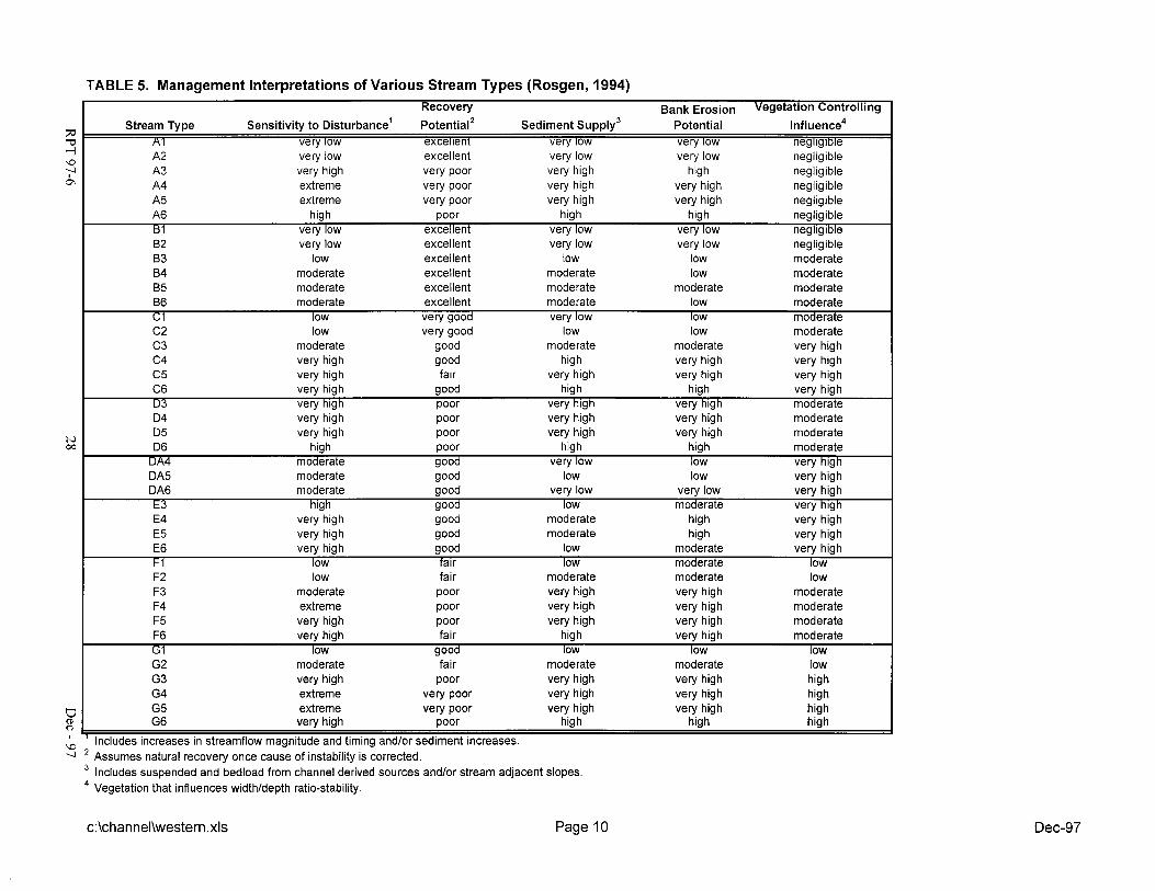
TABLE 5. Management Interpretations of Various Stream Types (Rosgen, 1994)
very low excellent very low very low negligible very high very poor very high high negligible extreme very poor very high very high negligible
7 '9
A5 extreme very poor very high very high negligible A6 high poor high high negligible B 1 very low excellent very low very low negllglble B2 very low excellent very low very low negligible B3 low excellent low low moderate B4 moderate excellent moderate low moderate 85 moderate excellent moderate moderate moderate B6 moderate excellent moderate low moderate C 1 low very good very low low moderate C2 low very good low low moderate
Recovery Bank Erosion Vegetation Controlling
Stream Type Sensitivity to ~isturbance' potential2 Sediment supply3 Potential lnfluence4 A1 very low excellent very low very low negllglble
C3 moderate good moderate moderate very high C4 very high good high very high very high C5 very high fair very high very high very high C6 very high good high high very high U3 very high poor very high very high moderate
very high very high
poor very high very high moderate poor very high very high moderate I
D6 high- poor high high^ moderate DA4 moderate good very low low very high DA5 moderate good low low very high DA6 moderate good very low very low very high t 3 high good low moderate very high E4 very high good moderate high very high E5 very high good moderate high very high E6 very high good low moderate very high k 1 low falr low moderate low F2 low fair moderate moderate low F3 moderate poor very high very high moderate F4 extreme poor very high very high moderate F5 very high poor very high very high moderate F6 very high fair high very high moderate G 1 low good low low low G2 moderate fair moderate moderate low G3 very high poor very high very high high G4 extreme very poor very high very high high G5 extreme very poor very high very high high G6 very high poor high high high
' Includes increases in streamflow magnitude and timing andlor sediment increases. Assumes natural recovery once cause of instability is corrected. Includes suspended and bedload from channel derived sources andlor stream adjacent slopes. Vegetation that influences widthldepth ratio-stability.
c:\channel\western.xls Page 10

APPENDIX B
General Stream Channel Reclamation Considerations
The following considerations should be taken into account whenever stream bypass, diversion or channelization activities are proposed. For more information consult ADF&G (1 986) "Alaska Habitat Management Guide - Guidelines for the Protection of Fish and Their Habitat."
A. Biological Considerations
1. What speciesllife stage of fish are present in the drainage system during the year?
2. What are the habitat needs and preferences of these speciesllife stages?
3. Does the time of proposed channel modification coincide with critical periods of migration, spawning, incubation, overwintering, or rearing of fish?
4. What types of natural habitat exist in presently unaltered stream sections (i.e., pool, riffle, cover, spawning substrate)?
5 . Will disruption or loss of a particular habitat type unreasonably adversely affect and species of life stage of fish?
6. Will instream cover, bank undercuts, or riparian cover be diminished?
7. Are there any chemical constituents of the substrate material that may adversely affect fish or their prey if reintroduced into the aquatic environment as suspended sediments?
8. Will stream channelization connect existing waterbodies?
9. How can your mine plan be developed to best preserve natural habitat attributes?
B. Hydraulic Considerations
1 . What is the shape and dimensions of the natural stream channel?
2. What is the natural channel meander pattern and channel slope?
3. What is the watershed's hydrograph? If not available, is an adjacent gauged stream available in a similar basin that can be used to calibrate the regional regression estimate?
4. What are the extremes in stream flow over a several year period of time?
RPT 97-6 Dec - 97

5 . What is the natural pool-riffle ratio?
6. What is the spacing between successive pools and riffles?
7. What are the stream bed and banks composed of! What is the median particle diameter (D,,)?
8. Will bank stabilization measures be needed to control erosion?
9. What effect will various instream structures have on channel conveyance capacity and bedload transport?
10. Will mining or subsequent reclamation adversely affect soil-water relationships within the riparian zone?
1 1. Will streambanks be revegetated with native species?
12. If the stream has not previously been mined, are the streambanks and adjacent floodplain underlain by permafrost?
13. What is the history of aufeis formation at this location?
Practical Considerations
1. Can your mining plan be modified to avoid or minimize instream impacts?
2. If channel diversion is necessary, can your mine plan be modified so that the stream only has to be moved once and placed back into a permanent channel?
3. Has the pay zone been adequately delineated and is it economically worth the added expense of properly diverting and reestablishing the stream?
RPT 97-6 Dec - 97

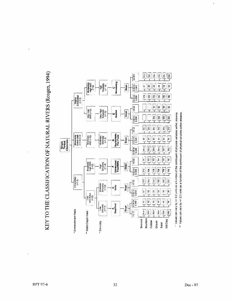
APPENDIX C Classification of Channel Types (Rosgen, 1994)
FLOODLPROWE AREA -, - - BANKPULL STAGE -
BW Descri~tion
Aa+ Deeply entrenched; vertical steps with deep scour pools; waterfalls; Slope > 10%.
A Entrenched, cascading steplpool stream; Slope 4 to 10%.
B Moderately entrenched, riffle dominated; Slope 2 to 4%.
C Meandering point-bar, riffle/pool alluvial channel; Slope < 2%.
D Braided channel wl longitudinal and transverse bars; Slope < 4%.
DA Anastomosing (multiple channels) with well vegetated bars; fine alluvium or lacuustrine soils; Slope < 0.5%.
E Incised, beaded tundra stream; high meander width ratio; Slope <2%.
F Entrenched meandering rifflelpool channel; Slope < 2%.
G Entrenched "gully" steplpool; Slope 2 to 4%.
RPT 97-6
RPT 97-6 Dec - 97