Embed Size (px)
Citation preview
Technical Report Documentation Page 1. Report No. FHWA/TX-08/0-5821-1
2. Government Accession No.
3. Recipient's Catalog No. 5. Report Date May 2008 Published: July 2008
4. Title and Subtitle GUIDELINES FOR ROUTINE MAINTENANCE OF CONCRETE PAVEMENT
6. Performing Organization Code
7. Author(s) Youn su Jung, Thomas J. Freeman, and Dan G. Zollinger
8. Performing Organization Report No. Report 0-5821-1 10. Work Unit No. (TRAIS)
9. Performing Organization Name and Address Texas Transportation Institute The Texas A&M University System College Station, Texas 77843-3135
11. Contract or Grant No. Project 0-5821 13. Type of Report and Period Covered Technical Report: September 2006 – February 2008
12. Sponsoring Agency Name and Address Texas Department of Transportation Research and Technology Implementation Office P.O. Box 5080 Austin, Texas 78763-5080
14. Sponsoring Agency Code
15. Supplementary Notes Project performed in cooperation with the Texas Department of Transportation and the Federal Highway Administration. Project Title: Develop Guidelines for Routine Maintenance of Concrete Pavement URL: http://tti.tamu.edu/documents/0-5821-1.pdf 16. Abstract
Concrete pavement has shown great performance in urban area and interstate highway settings for many years because of its low maintenance requirements and capability for long service life. However, rapidly increasing heavy traffic accelerates pavement deterioration and increases the need for more maintenance than in the past. If proper maintenance is not employed at low levels of deterioration, in a timely manner, acute degradation of pavement serviceability will occur and major repair costs may be needed.
This report discusses the visual identification of various distress types and introduces evaluation techniques using nondestructive testing (NDT), which are key to determining proper routine maintenance activities. According to the areas selected from the simplified checklist of visual distress types, falling weight deflectometer (FWD) for structural condition evaluation, ground penetration radar (GPR) for detecting voids below the slab and the presence of trapped water, and dynamic cone penetrometer (DCP) for estimating the in situ strength of base and subgrade soils are used to provide current information on pavement condition for selection of needed repair methods using a simple, systematic decision process. Key routine maintenances activities are categorized into five levels: performance monitoring, preservative, functional concrete pavement repair (CPR), structural CPR, and remove and replace. During field investigations, poorly performing areas were identified and possible fixes determined as a means of guideline development.
17. Key Words Routine Maintenance, Field Guidelines, Pavement Condition Evaluation, Decision Flowchart, Repair
18. Distribution Statement No restrictions. This document is available to the public through NTIS: National Technical Information Service Springfield, Virginia 22161 http://www.ntis.gov
19. Security Classif.(of this report) Unclassified
20. Security Classif.(of this page) Unclassified
21. No. of Pages 146
22. Price
Form DOT F 1700.7 (8-72) Reproduction of completed page authorized

GUIDELINES FOR ROUTINE MAINTENANCE OF CONCRETE
PAVEMENT
by
Youn su Jung Graduate Research Assistant
Texas Transportation Institute
Thomas J. Freeman Engineering Research Associate Texas Transportation Institute
and
Dan G. Zollinger Program Manager
Texas Transportation Institute
Report 0-5821-1 Project 0-5821
Project Title: Develop Guidelines for Routine Maintenance of Concrete Pavement
Performed in cooperation with the Texas Department of Transportation
and the Federal Highway Administration
May 2008 Published: July 2008
TEXAS TRANSPORTATION INSTITUTE The Texas A&M University System College Station, Texas 77843-3135

v
DISCLAIMER The contents of this report reflect the views of the authors, who are responsible
for the facts and the accuracy of the data presented herein. The contents do not
necessarily reflect the official view or policies of the Federal Highway Administration
(FHWA) or the Texas Department of Transportation (TxDOT). This report does not
constitute a standard, specification, or regulation. Its contents are not intended for
construction, bidding, or permit purposes. The use of names of specific products or
manufacturers listed herein does not imply endorsement of those products or
manufacturers. The engineer in charge of the project was Dan G. Zollinger, Texas P.E.
#67129.
vi
ACKNOWLEDGMENTS This project was conducted in cooperation with TxDOT and FHWA. The authors
wish to express their appreciation of the personnel of the Federal Highway
Administration and the Texas Department of Transportation for their support throughout
this project, as well as of the project coordinator, Dennis R. Cooley, P.E.; the project
director, Paul D. Montgomery, P.E.; and members of the Project Monitoring Committee.
vii
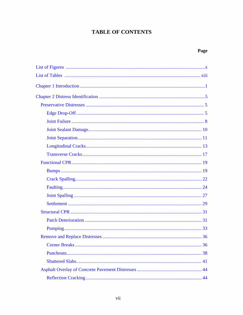
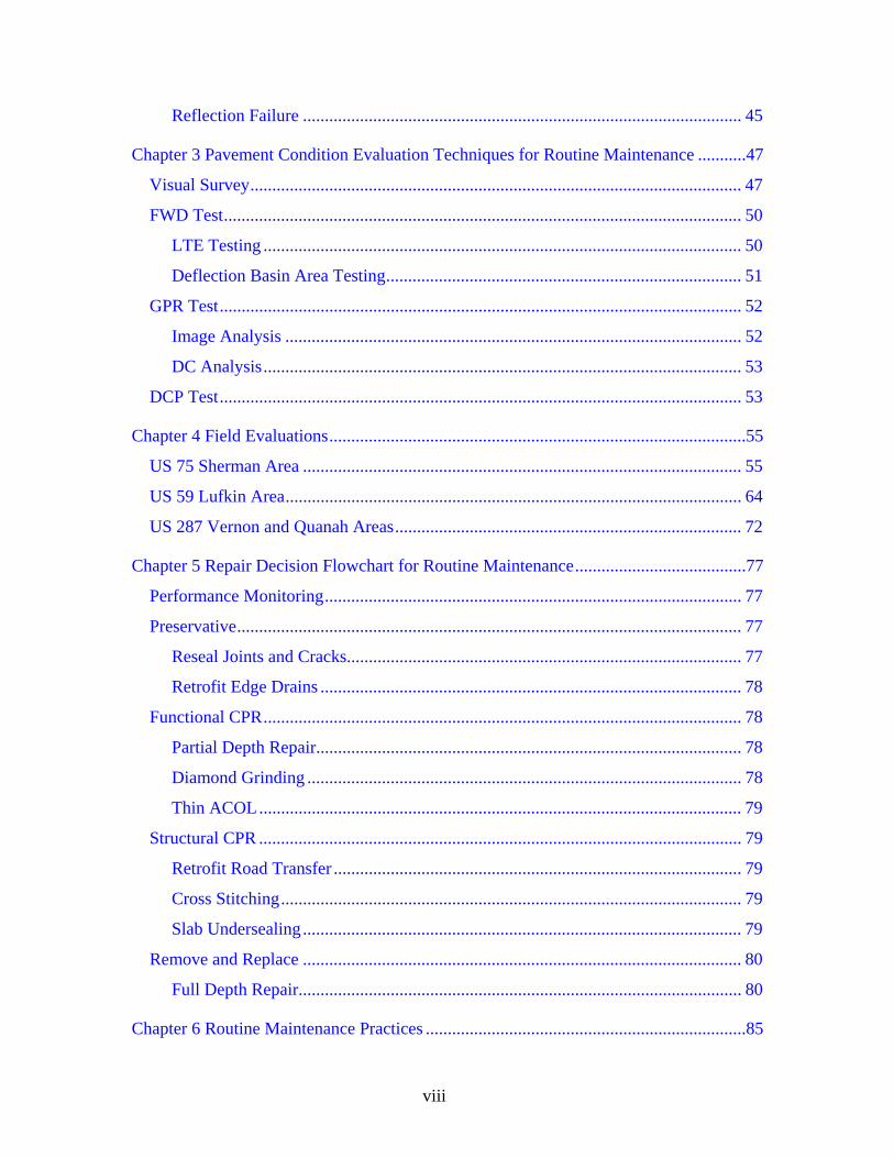
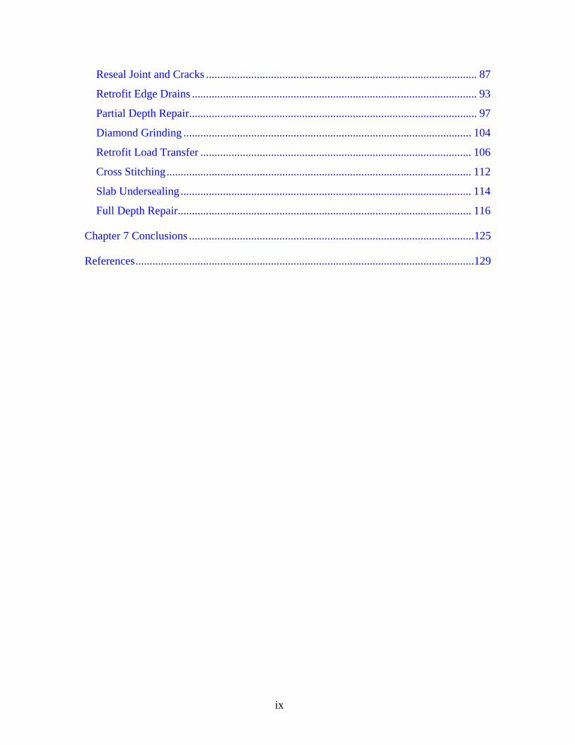
TABLE OF CONTENTS
Page
List of Figures .....................................................................................................................x
List of Tables .................................................................................................................. xiii
Chapter 1 Introduction .........................................................................................................1
Chapter 2 Distress Identification .........................................................................................5
Preservative Distresses ................................................................................................... 5
Edge Drop-Off ........................................................................................................... 5
Joint Failure ............................................................................................................... 8
Joint Sealant Damage............................................................................................... 10
Joint Separation........................................................................................................ 11
Longitudinal Cracks................................................................................................. 13
Transverse Cracks.................................................................................................... 17
Functional CPR............................................................................................................. 19
Bumps ...................................................................................................................... 19
Crack Spalling.......................................................................................................... 22
Faulting .................................................................................................................... 24
Joint Spalling ........................................................................................................... 27
Settlement ................................................................................................................ 29
Structural CPR .............................................................................................................. 31
Patch Deterioration .................................................................................................. 31
Pumping ................................................................................................................... 33
Remove and Replace Distresses ................................................................................... 36
Corner Breaks .......................................................................................................... 36
Punchouts................................................................................................................. 38
Shattered Slabs......................................................................................................... 41
Asphalt Overlay of Concrete Pavement Distresses ...................................................... 44
Reflection Cracking ................................................................................................. 44
viii
Reflection Failure .................................................................................................... 45
Chapter 3 Pavement Condition Evaluation Techniques for Routine Maintenance ...........47
Visual Survey................................................................................................................ 47
FWD Test...................................................................................................................... 50
LTE Testing ............................................................................................................. 50
Deflection Basin Area Testing................................................................................. 51
GPR Test....................................................................................................................... 52
Image Analysis ........................................................................................................ 52
DC Analysis............................................................................................................. 53
DCP Test....................................................................................................................... 53
Chapter 4 Field Evaluations...............................................................................................55
US 75 Sherman Area .................................................................................................... 55
US 59 Lufkin Area........................................................................................................ 64
US 287 Vernon and Quanah Areas............................................................................... 72
Chapter 5 Repair Decision Flowchart for Routine Maintenance.......................................77
Performance Monitoring............................................................................................... 77
Preservative................................................................................................................... 77
Reseal Joints and Cracks.......................................................................................... 77
Retrofit Edge Drains ................................................................................................ 78
Functional CPR............................................................................................................. 78
Partial Depth Repair................................................................................................. 78
Diamond Grinding ................................................................................................... 78
Thin ACOL.............................................................................................................. 79
Structural CPR .............................................................................................................. 79
Retrofit Road Transfer ............................................................................................. 79
Cross Stitching......................................................................................................... 79
Slab Undersealing.................................................................................................... 79
Remove and Replace .................................................................................................... 80
Full Depth Repair..................................................................................................... 80
Chapter 6 Routine Maintenance Practices .........................................................................85
ix
Reseal Joint and Cracks ................................................................................................ 87
Retrofit Edge Drains ..................................................................................................... 93
Partial Depth Repair...................................................................................................... 97
Diamond Grinding ...................................................................................................... 104
Retrofit Load Transfer ................................................................................................ 106
Cross Stitching............................................................................................................ 112
Slab Undersealing ....................................................................................................... 114
Full Depth Repair........................................................................................................ 116
Chapter 7 Conclusions .....................................................................................................125
References........................................................................................................................129
x
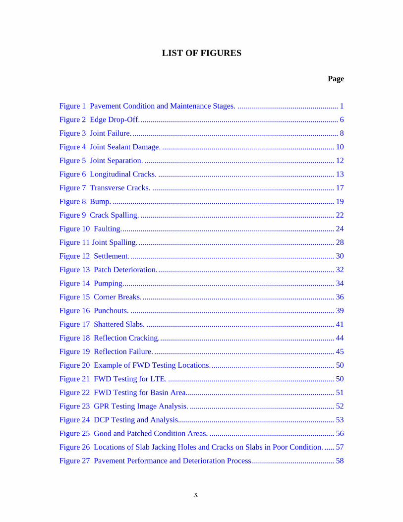
LIST OF FIGURES
Page
Figure 1 Pavement Condition and Maintenance Stages. ................................................... 1
Figure 2 Edge Drop-Off..................................................................................................... 6
Figure 3 Joint Failure. ........................................................................................................ 8
Figure 4 Joint Sealant Damage. ....................................................................................... 10
Figure 5 Joint Separation. ................................................................................................ 12
Figure 6 Longitudinal Cracks. ......................................................................................... 13
Figure 7 Transverse Cracks. ............................................................................................ 17
Figure 8 Bump. ................................................................................................................ 19
Figure 9 Crack Spalling. .................................................................................................. 22
Figure 10 Faulting............................................................................................................ 24
Figure 11 Joint Spalling. ................................................................................................... 28
Figure 12 Settlement. ....................................................................................................... 30
Figure 13 Patch Deterioration.......................................................................................... 32
Figure 14 Pumping........................................................................................................... 34
Figure 15 Corner Breaks.................................................................................................. 36
Figure 16 Punchouts. ....................................................................................................... 39
Figure 17 Shattered Slabs. ............................................................................................... 41
Figure 18 Reflection Cracking......................................................................................... 44
Figure 19 Reflection Failure. ........................................................................................... 45
Figure 20 Example of FWD Testing Locations............................................................... 50
Figure 21 FWD Testing for LTE. .................................................................................... 50
Figure 22 FWD Testing for Basin Area........................................................................... 51
Figure 23 GPR Testing Image Analysis. ......................................................................... 52
Figure 24 DCP Testing and Analysis............................................................................... 53
Figure 25 Good and Patched Condition Areas. ............................................................... 56
Figure 26 Locations of Slab Jacking Holes and Cracks on Slabs in Poor Condition. ..... 57
Figure 27 Pavement Performance and Deterioration Process.......................................... 58
xi
Figure 28 FWD Testing Result Analysis. ........................................................................ 60
Figure 29 GPR Image Analysis. ...................................................................................... 61
Figure 30 DCP Testing Results........................................................................................ 62
Figure 31 Findings from Sample Coring and Strength of Cores. .................................... 63
Figure 32 Test Sections.................................................................................................... 64
Figure 33 US 59 Asphalt Concrete (AC) Overlay Crack Repairs in Sections 1 and 2.... 65
Figure 34 US 59 Underlying JC Pavement Joint Repairs Using HMA in Section 3....... 66
Figure 35 US 59 Underlying JC Pavement Joint Repairs Using Fiber Screed
in Section 4. .................................................................................................... 67
Figure 36 US 59 Underlying JC Pavement Joint Repairs Using HMA and
Fabric Underseal in Section 5. ......................................................................... 68
Figure 37 Schematic Diagram of RDD and Sensor Array............................................... 69
Figure 38 Deflection Data of RDD Test. ......................................................................... 69
Figure 39 Deflection Data of RDD Test through Whole Section.................................... 70
Figure 40 Deflection Data of RDD Test at Joint Locations............................................. 70
Figure 41 LTE at Joint Locations. ................................................................................... 70
Figure 42 GPR Images along Wheel Path. ...................................................................... 71
Figure 43 Test Sections in Vernon................................................................................... 72
Figure 44 Repaired Section Using DBR and DG in Quanah........................................... 73
Figure 45 Load Transfer Efficiency of Test Sections in US 287..................................... 73
Figure 46 Basin Area of Test Sections on US 287. ......................................................... 74
Figure 47 Elastic Moduli of Test Sections on US 287..................................................... 74
Figure 48 GPR Image of Test Section in Quanah............................................................ 75
Figure 49 Coring in Poor Condition Section. .................................................................. 76
Figure 50 AC/Non-AC Overlaid JC Pavement Routine Maintenance
Decision Flowchart. ......................................................................................... 81
Figure 51 AC/Non-AC Overlaid CRC Pavement Routine Maintenance Decision
Flowchart. ........................................................................................................ 83
Figure 52 Details for Resealing Joints. ............................................................................ 87
Figure 53 Retrofit Transverse and Longitudinal Joints Sealant....................................... 88
Figure 54 Drainage Collector........................................................................................... 93

xii
Figure 55 Retrofitted Pavement Edge Drain.................................................................... 94
Figure 56 Subdrain System.............................................................................................. 94
Figure 57 Partial Depth Spall Repair. .............................................................................. 97
Figure 58 Spall Repair. .................................................................................................... 98
Figure 59 Details for Patching PCC Pavement................................................................ 98
Figure 60 US 59 Southbound Joint Repairs..................................................................... 99
Figure 61 Alternative Repair Strategy to Full Depth Repair for Deep Delamination. .. 100
Figure 62 Diamond Grinding......................................................................................... 104
Figure 63 Dowel Bar Retrofit Plan of Caltrans. ............................................................ 107
Figure 64 Dowel Bar Retrofit Plan of WSDOT............................................................. 108
Figure 65 Cross Stitching............................................................................................... 112
Figure 66 Slab Undersealing by Grout Injection. .......................................................... 114
Figure 67 Full Depth Repair Layouts and Joint Types. ................................................. 117
Figure 68 Full Depth Repair. ......................................................................................... 118
Figure 69 Joint Details for Repair.................................................................................. 119
Figure 70 CRC Pavement Full Depth Repair. ............................................................... 120
Figure 71 Repairing Detail for CRC Pavement. ............................................................ 120
Figure 72 Precast Concrete Slabs as Full Depth Repairs............................................... 121
xiii
LIST OF TABLES
Page
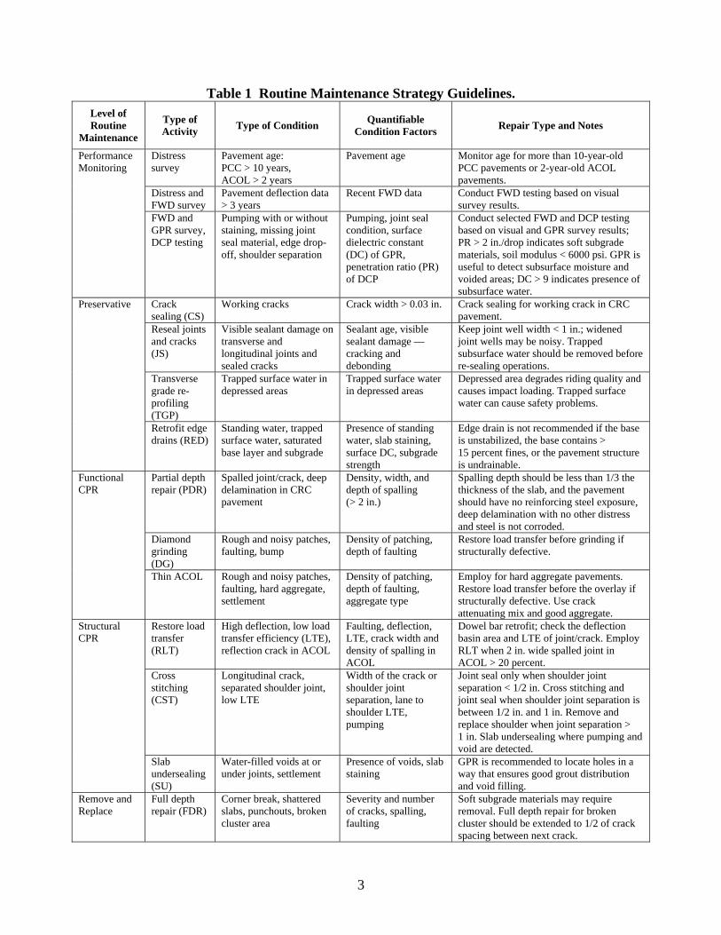
Table 1 Routine Maintenance Strategy Guidelines. .......................................................... 3
Table 2 Distress Types of Concrete Pavement. ................................................................. 5
Table 3 JC Pavement Condition Survey Form for Routine Maintenance. ...................... 48
Table 4 CRC Pavement Condition Survey Form for Routine Maintenance.................... 49
Table 5 JC Pavement Condition Survey of US 75 in Sherman. ...................................... 55
Table 6 Summary of Routine Maintenance Repairs. ....................................................... 85
Table 7 Strength Requirements for Dowel Bar Rretrofit Patching Material. ............... 111

xiv
1
CHAPTER 1 INTRODUCTION
Concrete pavement has shown great performance in urban area and interstate
highway settings for many years because of its low maintenance requirements and capability for long service life. However, rapidly increasing heavy traffic accelerates pavement deterioration and increases the need for more maintenance than in the past. If proper maintenance is not employed at low levels of deterioration, in a timely manner, acute degradation of pavement serviceability will occur and major repair costs may be needed.
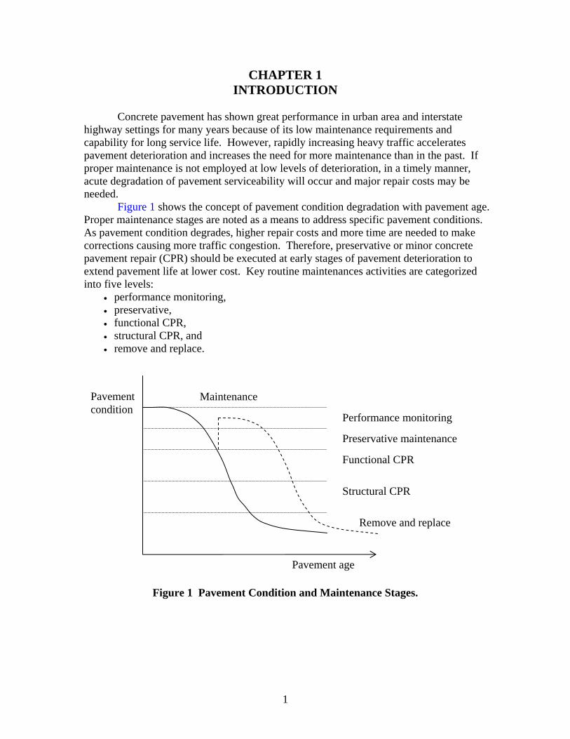
Figure 1 shows the concept of pavement condition degradation with pavement age. Proper maintenance stages are noted as a means to address specific pavement conditions. As pavement condition degrades, higher repair costs and more time are needed to make corrections causing more traffic congestion. Therefore, preservative or minor concrete pavement repair (CPR) should be executed at early stages of pavement deterioration to extend pavement life at lower cost. Key routine maintenances activities are categorized into five levels:
• performance monitoring, • preservative, • functional CPR, • structural CPR, and • remove and replace.
Figure 1 Pavement Condition and Maintenance Stages.
Pavement age
Pavement condition
Performance monitoring
Preservative maintenance
Functional CPR
Structural CPR
Remove and replace
Maintenance
2
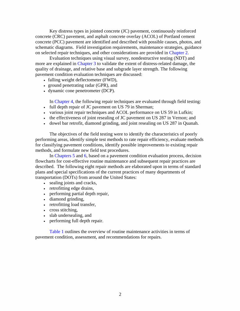
Key distress types in jointed concrete (JC) pavement, continuously reinforced concrete (CRC) pavement, and asphalt concrete overlay (ACOL) of Portland cement concrete (PCC) pavement are identified and described with possible causes, photos, and schematic diagrams. Field investigation requirements, maintenance strategies, guidance on selected repair techniques, and other considerations are provided in Chapter 2.
Evaluation techniques using visual survey, nondestructive testing (NDT) and more are explained in Chapter 3 to validate the extent of distress-related damage, the quality of drainage, and relative base and subgrade layer strength. The following pavement condition evaluation techniques are discussed:
• falling weight deflectometer (FWD), • ground penetrating radar (GPR), and • dynamic cone penetrometer (DCP).
In Chapter 4, the following repair techniques are evaluated through field testing:
• full depth repair of JC pavement on US 79 in Sherman; • various joint repair techniques and ACOL performance on US 59 in Lufkin; • the effectiveness of joint resealing of JC pavement on US 287 in Vernon; and • dowel bar retrofit, diamond grinding, and joint resealing on US 287 in Quanah.
The objectives of the field testing were to identify the characteristics of poorly
performing areas, identify simple test methods to rate repair efficiency, evaluate methods for classifying pavement conditions, identify possible improvements to existing repair methods, and formulate new field test procedures.
In Chapters 5 and 6, based on a pavement condition evaluation process, decision flowcharts for cost-effective routine maintenance and subsequent repair practices are described. The following eight repair methods are elaborated upon in terms of standard plans and special specifications of the current practices of many departments of transportation (DOTs) from around the United States:
• sealing joints and cracks, • retrofitting edge drains, • performing partial depth repair, • diamond grinding, • retrofitting load transfer, • cross stitching, • slab undersealing, and • performing full depth repair.
Table 1 outlines the overview of routine maintenance activities in terms of
pavement condition, assessment, and recommendations for repairs.
3
Table 1 Routine Maintenance Strategy Guidelines. Level of Routine
Maintenance
Type of Activity Type of Condition Quantifiable
Condition Factors Repair Type and Notes
Distress survey
Pavement age: PCC > 10 years, ACOL > 2 years
Pavement age Monitor age for more than 10-year-old PCC pavements or 2-year-old ACOL pavements.
Distress and FWD survey
Pavement deflection data > 3 years
Recent FWD data Conduct FWD testing based on visual survey results.
Performance Monitoring
FWD and GPR survey, DCP testing
Pumping with or without staining, missing joint seal material, edge drop-off, shoulder separation
Pumping, joint seal condition, surface dielectric constant (DC) of GPR, penetration ratio (PR) of DCP
Conduct selected FWD and DCP testing based on visual and GPR survey results; PR > 2 in./drop indicates soft subgrade materials, soil modulus < 6000 psi. GPR is useful to detect subsurface moisture and voided areas; DC > 9 indicates presence of subsurface water.
Crack sealing (CS)
Working cracks Crack width > 0.03 in. Crack sealing for working crack in CRC pavement.
Reseal joints and cracks (JS)
Visible sealant damage on transverse and longitudinal joints and sealed cracks
Sealant age, visible sealant damage — cracking and debonding
Keep joint well width < 1 in.; widened joint wells may be noisy. Trapped subsurface water should be removed before re-sealing operations.
Transverse grade re-profiling (TGP)
Trapped surface water in depressed areas
Trapped surface water in depressed areas
Depressed area degrades riding quality and causes impact loading. Trapped surface water can cause safety problems.
Preservative
Retrofit edge drains (RED)
Standing water, trapped surface water, saturated base layer and subgrade
Presence of standing water, slab staining, surface DC, subgrade strength
Edge drain is not recommended if the base is unstabilized, the base contains > 15 percent fines, or the pavement structure is undrainable.
Partial depth repair (PDR)
Spalled joint/crack, deep delamination in CRC pavement
Density, width, and depth of spalling (> 2 in.)
Spalling depth should be less than 1/3 the thickness of the slab, and the pavement should have no reinforcing steel exposure, deep delamination with no other distress and steel is not corroded.
Diamond grinding (DG)
Rough and noisy patches, faulting, bump
Density of patching, depth of faulting
Restore load transfer before grinding if structurally defective.
Functional CPR
Thin ACOL Rough and noisy patches, faulting, hard aggregate, settlement
Density of patching, depth of faulting, aggregate type
Employ for hard aggregate pavements. Restore load transfer before the overlay if structurally defective. Use crack attenuating mix and good aggregate.
Restore load transfer (RLT)
High deflection, low load transfer efficiency (LTE), reflection crack in ACOL
Faulting, deflection, LTE, crack width and density of spalling in ACOL
Dowel bar retrofit; check the deflection basin area and LTE of joint/crack. Employ RLT when 2 in. wide spalled joint in ACOL > 20 percent.
Cross stitching (CST)
Longitudinal crack, separated shoulder joint, low LTE
Width of the crack or shoulder joint separation, lane to shoulder LTE, pumping
Joint seal only when shoulder joint separation < 1/2 in. Cross stitching and joint seal when shoulder joint separation is between 1/2 in. and 1 in. Remove and replace shoulder when joint separation > 1 in. Slab undersealing where pumping and void are detected.
Structural CPR
Slab undersealing (SU)
Water-filled voids at or under joints, settlement
Presence of voids, slab staining
GPR is recommended to locate holes in a way that ensures good grout distribution and void filling.
Remove and Replace
Full depth repair (FDR)
Corner break, shattered slabs, punchouts, broken cluster area
Severity and number of cracks, spalling, faulting
Soft subgrade materials may require removal. Full depth repair for broken cluster should be extended to 1/2 of crack spacing between next crack.

5
CHAPTER 2 DISTRESS IDENTIFICATION
This chapter described the distresses types, possible causes, investigation
requirements, and maintenance strategies identified from research development and materials prepared by Scullion, Coppock, and C. Von Holdt (1). The pictures of distresses come from the TxDOT distress manual (2), the Strategic Highway Research Program distress manual (3), and pictures taken during this research.
This chapter presents the name and description of the distress, along with a variety of pictures. It then provides guidance on possible repair techniques and other considerations. The distresses are listed alphabetically in Table 2.
Table 2 Distress Types of Concrete Pavement.
Preservative Functional CPR Structural CPR Remove and Replace
Edge Drop-Off Joint Failure Joint Sealant Damage Joint Separation Longitudinal Cracks Transverse Cracks
Bumps Crack Spalling Faulting Joint Spalling Settlement
Patch Deterioration Pumping
Corner Break Punchouts Shattered Slabs
PRESERVATIVE DISTRESSES
In addition to these distresses, it is important to check that drainage is performing properly and that no water remains on the pavement or in the ditches. This may require reprofiling the shoulder or regrading and reprofiling the ditches. Edge Drop-Off
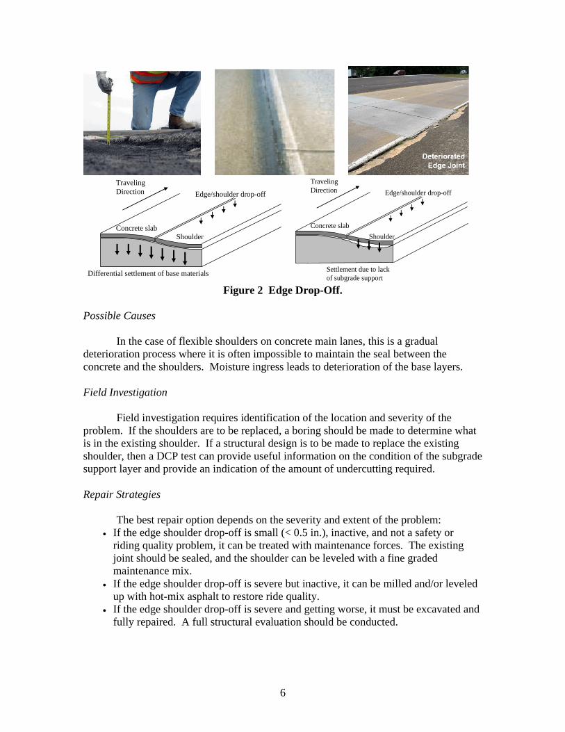
Edge/shoulder drop-offs are normally associated with the use of a flexible shoulder on pavements where the main lanes are concrete. Large differences in elevation of the main lanes versus the shoulder can be safety problems and should be addressed by maintenance forces. Frequently, the edge/shoulder joint has deteriorated and is now open. Water will enter this joint and cause erosion of the layers supporting the concrete. This can lead to rapid failure of the concrete slab. This problem has been largely eliminated in Texas in new pavements because of the use of tied concrete shoulders. The edge/shoulder problem is particularly severe with old, narrow jointed concrete pavements, which may have been only 18 or 20 ft wide. Figure 2 shows some examples of edge drop-off and schematic diagrams.
6
Edge/shoulder drop-off
Differential settlement of base materials
Concrete slab Shoulder
Traveling Direction
Concrete slab Shoulder
Traveling Direction
Settlement due to lack of subgrade support
Edge/shoulder drop-off
Figure 2 Edge Drop-Off.
Possible Causes
In the case of flexible shoulders on concrete main lanes, this is a gradual deterioration process where it is often impossible to maintain the seal between the concrete and the shoulders. Moisture ingress leads to deterioration of the base layers. Field Investigation
Field investigation requires identification of the location and severity of the problem. If the shoulders are to be replaced, a boring should be made to determine what is in the existing shoulder. If a structural design is to be made to replace the existing shoulder, then a DCP test can provide useful information on the condition of the subgrade support layer and provide an indication of the amount of undercutting required. Repair Strategies
The best repair option depends on the severity and extent of the problem: • If the edge shoulder drop-off is small (< 0.5 in.), inactive, and not a safety or
riding quality problem, it can be treated with maintenance forces. The existing joint should be sealed, and the shoulder can be leveled with a fine graded maintenance mix.
• If the edge shoulder drop-off is severe but inactive, it can be milled and/or leveled up with hot-mix asphalt to restore ride quality.
• If the edge shoulder drop-off is severe and getting worse, it must be excavated and fully repaired. A full structural evaluation should be conducted.
7
Routine Maintenance Typical routine maintenance, restoration, and structural rehabilitation options for
concrete pavements are provided below. Repair alternatives can consist of any combination of these options and other repair methods that are not listed.
Crack/Joint Sealing. Crack sealing prevents water intrusion into the longitudinal joints and the development of secondary deterioration, so all longitudinal joints should be sealed on a routine basis.
Patching with Asphalt Concrete. Patching with asphalt concrete can be used to
level the edge shoulder drop-off if it is inactive. If the edge shoulder drop-off is active and if traffic is driving over this joint, then this is a temporary measure only.
Do Nothing. If the edge shoulder drop-off is shallow, does not present a safety or
riding quality problem, and no cracks are present, doing nothing may be feasible. Maintenance Options
Full Depth Repair. Full depth repair reinstates the structural integrity of the shoulder. This repair is feasible for active edge shoulder drop-offs and for repairing localized structural problems.
Shoulder Retrofitting. In severe cases the existing shoulder will need to be completely removed. If traffic will drive over the shoulder joint, then a full structural design needs to be conducted.
Edge Drain Retrofitting. This option should be considered if the only concern is moisture ingress at the longitudinal joint and traffic will not be driving over the installed drainage system. Structural Rehabilitation Options
Localized edge shoulder drop-offs are normally treated by the maintenance
options described above. However, in the very rare occurrence that the edge shoulder drop-offs are widespread, then a full forensic investigation should be undertaken to identify the causes and optimum repair strategy. Prevention
Use tied concrete shoulders in all new concrete pavement designs.
8
Joint Failure
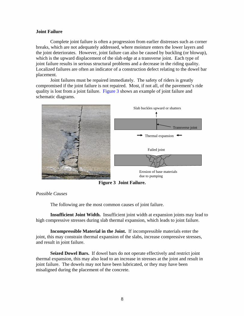
Complete joint failure is often a progression from earlier distresses such as corner breaks, which are not adequately addressed, where moisture enters the lower layers and the joint deteriorates. However, joint failure can also be caused by buckling (or blowup), which is the upward displacement of the slab edge at a transverse joint. Each type of joint failure results in serious structural problems and a decrease in the riding quality. Localized failures are often an indicator of a construction defect relating to the dowel bar placement.
Joint failures must be repaired immediately. The safety of riders is greatly compromised if the joint failure is not repaired. Most, if not all, of the pavement’s ride quality is lost from a joint failure. Figure 3 shows an example of joint failure and schematic diagrams.
Erosion of base materials due to pumping
Failed joint
Transverse joint
Thermal expansion
Slab buckles upward or shatters
Figure 3 Joint Failure.
Possible Causes
The following are the most common causes of joint failure.
Insufficient Joint Width. Insufficient joint width at expansion joints may lead to high compressive stresses during slab thermal expansion, which leads to joint failure.
Incompressible Material in the Joint. If incompressible materials enter the
joint, this may constrain thermal expansion of the slabs, increase compressive stresses, and result in joint failure.
Seized Dowel Bars. If dowel bars do not operate effectively and restrict joint
thermal expansion, this may also lead to an increase in stresses at the joint and result in joint failure. The dowels may not have been lubricated, or they may have been misaligned during the placement of the concrete.
9
Lack of Subgrade Support. Lack of subgrade support at the joint due to pumping may cause large slab deflections. These deflections may cause progressive cracking and settlement until joint failure occurs.
Nonstandard Joint Designs. In the 1960s researchers tried a range of
nonstandard joint designs to replace the labor-intensive dowel bars. The most widely used were the wrinkle-tin joints. Over time these joints deteriorated, which often resulted in locked joints and subsequent joint failure. Field Investigation
Guidelines for the identification of the most common causes of distress are as follows:
• Visually inspect the joints for incompressible materials. • If it is suspected that the dowel bars may have seized, take cores at the joint. Also
conduct a load transfer test with an FWD. Seized joints often have an LTE greater than 100 percent.
• Conduct a ground-coupled GPR survey to check for the location of the dowel bars. Repair Strategies
The only maintenance technique that is effective for the repair of joint failure is full depth repair. If joint failures are widespread, rehabilitation of the pavement should be considered. Routine Maintenance
Crack/Joint Sealing. Crack sealing helps keep the cracks clear of debris, which may reduce joint failures.
Patching with Asphalt Concrete. Patching with asphalt concrete can be used as a stopgap measure to temporarily improve ride quality. However, such patching may not last very long under traffic loading.
Do Nothing. Joint failures normally present a safety problem and should be
repaired as soon as possible. This is not a feasible option. Maintenance Options
Full Depth Repair. Full depth repair reinstates the structural integrity of the
pavement. This repair is feasible for joint failures. Structural Rehabilitation Options
The selection of an appropriate type of structural rehabilitation option depends on numerous project factors other than the cause of distress. Any of the following structural
10
rehabilitation options may be appropriate and should be evaluated on a case by case basis:
• hot mixed asphalt (HMA) overlay, • thin-bonded concrete overlay, • unbonded concrete overlay, • flexible base overlay and HMA overlay, • rubblization and HMA overlay, • crack and seat with flexible base overlay and HMA overlay, and • reconstruction.
Prevention
The following practices can minimize the occurrence of joint failure: • Frequently inspect and maintain joints to identify and react to joint sealant and
incompressible material problems. • Properly install load transfer devices at joints. • Clean joints properly before overlaying the pavement.
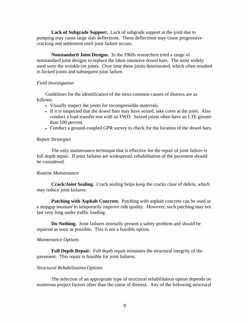
Joint Sealant Damage
Joint seal extrusion occurs when the joint sealant is squeezed from the joint. Extrusion may occur at longitudinal joints but is most common at transverse joints. Figure 4 shows an example of joint seal damage and a schematic diagram.
Transverse joint
Thermal expansion
Sealant squeezed from joint
Figure 4 Joint Sealant Damage.
Possible Causes
The following are causes of joint sealant extrusion. Excessive Compressive Forces at the Joint. Excessive compressive forces at
the joint resulting from high thermal expansion or slab creep may squeeze the sealant out of the joint.
Sealant Deterioration. Deteriorated sealant as a result of adhesive failure,
cohesive failure, or abnormal ageing may extrude from the joint.
11
Improper Joint Construction. Improper joint construction, such as inadequate
groove shape, too much sealant, and failure to clean joint properly prior to sealing, may lead to sealant extrusion.
Traffic Action. Once the joint seal has initiated, traffic action may pull the
sealant from the joint.
Field Investigation
Guidelines for the identification of the most common causes of distress are as follows:
• Insufficient joint widths should be identified visually. Inspect the slab size to determine if extrusion is due to high thermal expansion or slab creep.
• Deteriorated sealant can be inspected by inserting a knife blade into the joint face and then twisting. Effortless penetration indicates a lack of adhesion.
• Joints can be visually inspected to determine if improper joint construction is the cause of the joint failure.
Repair Strategies
Joint sealant extrusion will not cause a structural or safety threat initially. If the joint sealant extrusion is left untreated, water and incompressible materials may infiltrate into the joint and joint spalling or joint failure may result. Maintenance Options
Joint sealant extrusion should only be repaired by cleaning the joint and resealing. If the joint is left untreated, water and incompressible materials may enter the joint and create secondary problems. Prevention
The following practices can minimize the occurrence of joint failure: • Frequently inspect and maintain joints to identify and react to joint sealant
extrusion problems early. • Properly install joint sealant. • Use high quality joint sealant.
Joint Separation
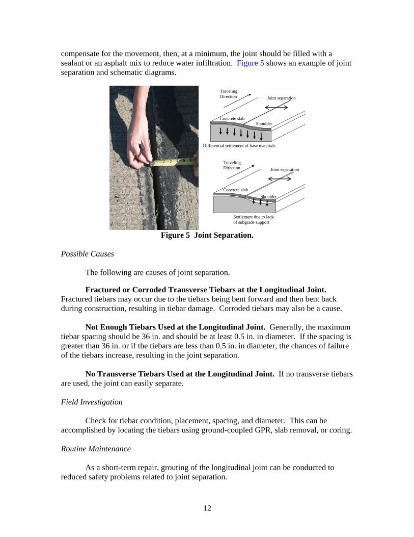
Joint separation is the lateral slippage of slabs resulting in the widening of a longitudinal joint. Joint separation usually occurs between the traffic lane and the shoulder. Lane separation is not considered serious unless water can easily infiltrate into the joint. The infiltration of water may cause additional damage or movement. Once the joint separates, the infiltration of water may cause damage to the underlying layers, additional movement, or structural problems. If a leveling course is not used to
12
compensate for the movement, then, at a minimum, the joint should be filled with a sealant or an asphalt mix to reduce water infiltration. Figure 5 shows an example of joint separation and schematic diagrams.
Joint separation
Differential settlement of base materials
Concrete slab Shoulder
Traveling Direction
Joint separation
Concrete slab Shoulder
Traveling Direction
Settlement due to lack of subgrade support
Figure 5 Joint Separation.
Possible Causes
The following are causes of joint separation.
Fractured or Corroded Transverse Tiebars at the Longitudinal Joint. Fractured tiebars may occur due to the tiebars being bent forward and then bent back during construction, resulting in tiebar damage. Corroded tiebars may also be a cause.
Not Enough Tiebars Used at the Longitudinal Joint. Generally, the maximum tiebar spacing should be 36 in. and should be at least 0.5 in. in diameter. If the spacing is greater than 36 in. or if the tiebars are less than 0.5 in. in diameter, the chances of failure of the tiebars increase, resulting in the joint separation.
No Transverse Tiebars Used at the Longitudinal Joint. If no transverse tiebars are used, the joint can easily separate. Field Investigation
Check for tiebar condition, placement, spacing, and diameter. This can be accomplished by locating the tiebars using ground-coupled GPR, slab removal, or coring. Routine Maintenance
As a short-term repair, grouting of the longitudinal joint can be conducted to
reduced safety problems related to joint separation.
13
Maintenance Options
If the joint has not separated more than 0.5 in., then cross stitching and stapling
may be options. Prevention
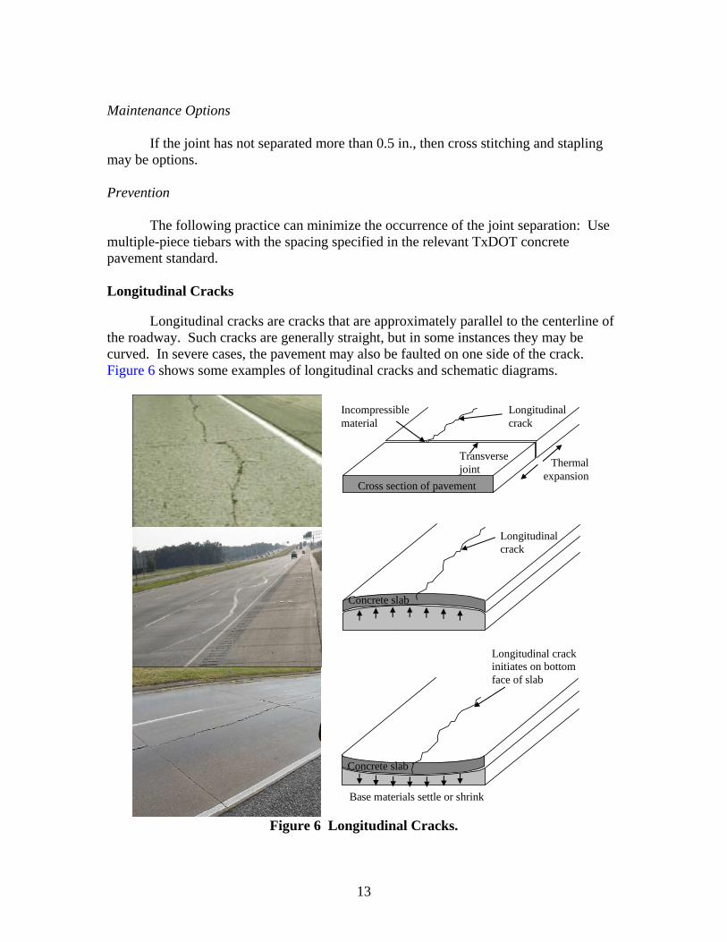
The following practice can minimize the occurrence of the joint separation: Use multiple-piece tiebars with the spacing specified in the relevant TxDOT concrete pavement standard. Longitudinal Cracks
Longitudinal cracks are cracks that are approximately parallel to the centerline of the roadway. Such cracks are generally straight, but in some instances they may be curved. In severe cases, the pavement may also be faulted on one side of the crack. Figure 6 shows some examples of longitudinal cracks and schematic diagrams.
Longitudinal crack
Thermal expansion
Transverse joint
Incompressible material
Cross section of pavement
Swelling base materials
Longitudinal crack initiates on bottom face of slab
Base materials settle or shrink
Concrete slab
Longitudinal crack
Concrete slab
Figure 6 Longitudinal Cracks.
14
Possible Causes
The following are the most common causes of longitudinal cracking. Improper Construction Joint Location. In some cases improper joint
construction can be a cause of longitudinal cracking, but in others the location of the longitudinal joint is not ideally placed relative to the width of paving. Even if the sawing of the joints is done in a timely manner after placement (the recommended timing is no later than 12 hours), problems may still occur. Most problems can be avoided when notching is done early enough, but in order for any sawcutting to be effective, it should be located approximately in the center of the paving width (for two-lane construction). These cracks occur early in pavement life and run fairly straight and parallel to the centerline.
Loss of Foundation Support. Improper compaction, inadequate stabilization, and/or water ingress may result in a loss of foundation support and differential settlement. This may cause the pavement to fault due to bending stresses, causing a longitudinal crack to form at the surface of the pavement. Cracks from this cause may occur at any stage of pavement life and normally run in a curved shape along the road.
Reflection Cracking from Stabilized Base. A cracked stabilized base layer may cause reflection cracking to propagate upward through the concrete layer. Cracks from this cause normally occur in the early stages of pavement life in pavements where stabilized bases are used.
The following are some less common causes.
Heaving Up of High Plasticity Index (PI) Swelling Soils. Swelling soils may result in an upward movement of the pavement. This upward movement creates bending stresses throughout the thickness of the slab. Since the tensile bending stresses are occurring on the top surface of the slab, the longitudinal crack may initiate on the top surface. Cracks from this cause may occur at any time during pavement life.
Edge Drying of High PI Swelling Soils. Edge drying of highly plastic soils may cause shrinkage and longitudinal cracking of the subgrade. This crack may propagate upward through the base layers and the concrete layer to form a longitudinal crack. These cracks may occur at any time during pavement life. They are typically related to subgrade soils having a PI of more than 35. Contributing factors include summer drought, steep side slopes, and roadside trees, all of which contribute to the drying out of the subgrade.
Warping and Curling Stresses. Warping and curling stresses in jointed pavements may initiate a longitudinal crack. Temperature differentials may cause the edges of the slab to curl upward. The weight of the slab restrains the slab from curling, thereby creating tensile stresses at the top of the slab, which may cause a longitudinal crack to form from the top downward. This longitudinal crack usually forms at the center
15
of the slab. Cracks from this cause may occur at any time during pavement life but normally occur during periods of large temperature differentials. Shoulders that are not tied, poor bond between the slab and the subbase, and large slab dimensions may be contributing factors.
Poor Construction Practices. In a recent forensic study, longitudinal cracking of the slab was attributed to a soft layer that was found on top of the asphalt base layer. The cracking was attributed to heavy rainfall that occurred after the placement of the steel. This rain washed a soft soil layer into the section, and the soil was not removed prior to placing the concrete. Field Investigation
Guidelines for the identification of the most common causes of distress are as follows:
• If the cracks run straight and parallel to the centerline and no faulting has occurred, then problems with improper joint construction or location are suspected. Take cores at the longitudinal joint to see if full depth cracks have formed at the joint.
• If the cracks are curved and the pavement has either faulted or there is a substantial change in cross slope due to differential settlement (as measured by a straight edge), then the loss of foundation support is suspected. Conduct a DCP investigation and take a soil sample of the subgrade soil in the settled area. Check the amount and type of stabilizer used. Research has shown that with clay soils, lime stabilizer contents in excess of 6 percent are required to provide permanent stabilization.
• If the pavement has a stabilized base layer and reflection cracking is suspected, take cores at the longitudinal crack to see if cracks propagate through all layers.
Laboratory Investigation
Laboratory testing is generally not required to validate the cause of longitudinal cracking. One area to be considered is the width of the paving lane versus the location of the sawcut longitudinal joint. However, if problems are suspected in the subgrade, then Shelby tube samples should be extracted and the samples used to map soil strata and test if material properties meet design specifications. If inadequate stabilization is suspected, see the TxDOT stabilization guidelines to determine the stabilization requirements. Repair Strategies
The best repair option depends on the cause of the cracks, the presence of other distresses, and possibly numerous other factors. The first decision is whether to perform routine maintenance, maintenance, or structural rehabilitation of the pavement. The basis for this decision is an understanding of the causes of the distress, which should give an indication of how the pavement will perform in the future. The following guidelines are given:
16
• If the cause of the cracks indicates that the cracks should remain fairly inactive over time, routine maintenance should be adequate.
• If the cause of the cracks indicates that the cracks will be active over time but is not the result of widespread structural deficiencies, maintenance should be adequate.
• If the cause of the cracks indicates widespread structural deficiencies over the length of the pavement, rehabilitation should be considered.
An understanding of the future deterioration of the pavement and all other
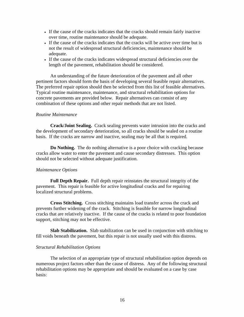
pertinent factors should form the basis of developing several feasible repair alternatives. The preferred repair option should then be selected from this list of feasible alternatives. Typical routine maintenance, maintenance, and structural rehabilitation options for concrete pavements are provided below. Repair alternatives can consist of any combination of these options and other repair methods that are not listed. Routine Maintenance
Crack/Joint Sealing. Crack sealing prevents water intrusion into the cracks and the development of secondary deterioration, so all cracks should be sealed on a routine basis. If the cracks are narrow and inactive, sealing may be all that is required.
Do Nothing. The do nothing alternative is a poor choice with cracking because cracks allow water to enter the pavement and cause secondary distresses. This option should not be selected without adequate justification. Maintenance Options
Full Depth Repair. Full depth repair reinstates the structural integrity of the pavement. This repair is feasible for active longitudinal cracks and for repairing localized structural problems.
Cross Stitching. Cross stitching maintains load transfer across the crack and prevents further widening of the crack. Stitching is feasible for narrow longitudinal cracks that are relatively inactive. If the cause of the cracks is related to poor foundation support, stitching may not be effective.
Slab Stabilization. Slab stabilization can be used in conjunction with stitching to fill voids beneath the pavement, but this repair is not usually used with this distress. Structural Rehabilitation Options
The selection of an appropriate type of structural rehabilitation option depends on numerous project factors other than the cause of distress. Any of the following structural rehabilitation options may be appropriate and should be evaluated on a case by case basis:
17
• HMA overlay, • thin-bonded concrete overlay, • unbonded concrete overlay, • flexible base overlay and HMA overlay, • rubblization and HMA overlay, • crack and seat with flexible base overlay and HMA overlay, and • reconstruction.
Prevention
The following practices can minimize the occurrence of longitudinal cracking: • Avoid paving widths that inhibit the proper location of the longitudinal sawcut
joint. • Limit the slab width (maximum width = 15 ft). • Saw joints as quickly as possible (as soon as the concrete can support the sawing
equipment and no later than 24 hours after placement). • Provide a permanent foundation layer consisting of a designed base and stabilized
layer. • Provide adequate drainage to reduce moisture content changes to the base
materials. • Reseal joints on a regular basis.
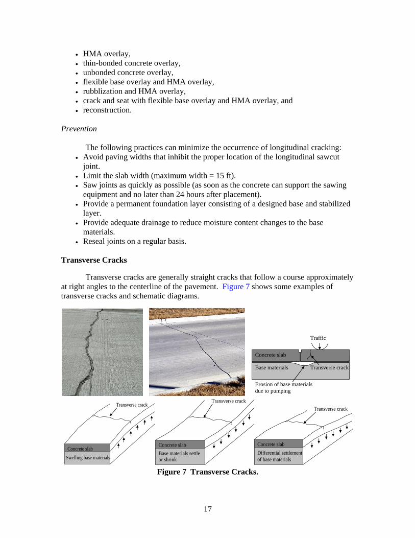
Transverse Cracks
Transverse cracks are generally straight cracks that follow a course approximately at right angles to the centerline of the pavement. Figure 7 shows some examples of transverse cracks and schematic diagrams.
Traffic
Transverse crack
Concrete slab
Base materials
Erosion of base materials due to pumping
Swelling base materials Concrete slab
Transverse crack
Base materials settle or shrink
Concrete slab
Transverse crack
Differential settlement of base materials
Concrete slab
Transverse crack
Figure 7 Transverse Cracks.
18
Possible Causes
Improper Joint Design - Excessive slab length is a joint location design error that may result in excessive tensile stresses in the slab and lead to transverse cracking.
Improper Joint Construction - Improper joint construction by failing to saw joints soon enough or deep enough may cause transverse cracks to form away from the joint.
Improper Slab Design or Construction - Improper slab design or construction resulting in inadequate slab thickness or inadequate material strength may lead to transverse cracks.
Swelling Soils - Swelling soils may result in upward movement of the pavement and cause excessive tensile stresses at the top of the slab, which may initiate transverse cracks from the top down.
Loss of Foundation Support - Loss of foundation support may result in excessive bending stresses and the development of transverse cracks. This may be from the erosion of base material at the joint or elsewhere in the slab.
Frost Heave. Frost heave of the underlying soils may result in upward movement of the pavement and cause excessive tensile stresses at the top of the slab, which may initiate transverse cracks from the top down.
The development of transverse cracks may be accelerated by warping and curling stresses in the slab, but these stresses are not expected to be the primary cause of transverse cracks. Field Investigation
Inspect slab dimensions to determine if of excessive length:
• Take a core through the joint to inspect if the joints are cracked through. • Take a core through the dowels to inspect if they are seized. • Take a core to evaluate the slab thickness and material strength. • If swelling soils are suspected, take soil samples for laboratory testing. • Take cores or use GPR to inspect for voids and loss of foundation support. • Take cores to determine is frost heave has produced upward expansion of the slab.
Laboratory Investigation
The following laboratory testing may be required: • material strength test — splitting tensile strength test (TxDOT Test Method
Tex-421-A), • sulfate tests, and • Atterberg limits.
19
Maintenance Options
The following repair strategies are recommended: • If the transverse cracks are inactive and no secondary distresses have occurred, the
cracks can be left unrepaired or sealed if wide enough. • If the transverse crack is active due to either swelling soils or loss of foundation
support, the base materials must be treated with full depth repair. Prevention
The following practices can minimize the occurrence of transverse cracking: • adequate design by limiting slab length, • appropriate sawing of the joints, • adequate dowel bar placement to prevent seizure, • adequate slab thickness design and concrete strength, • proper drainage, • stabilized base materials, and • adequate compaction.
FUNCTIONAL CPR
Functional distresses are more serious than preservative distresses and cause roughness problems with the pavement. The deterioration rate on these distresses is usually quite slow and provides many opportunities for repair. Bumps
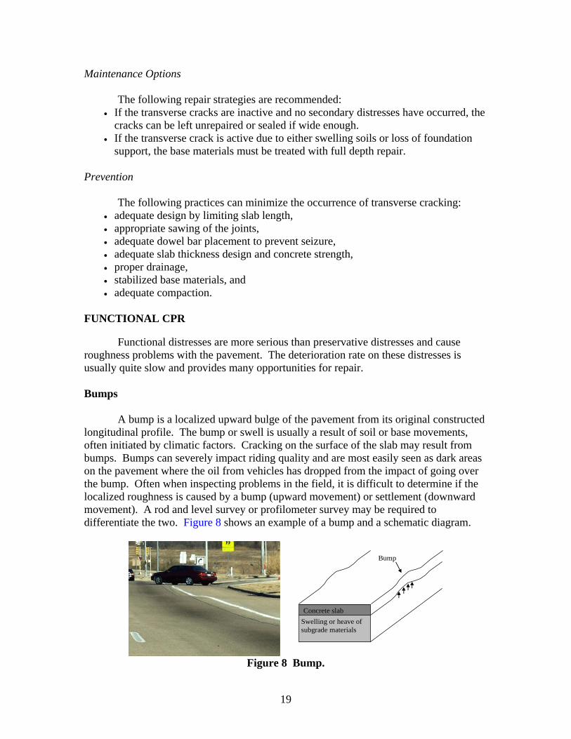
A bump is a localized upward bulge of the pavement from its original constructed longitudinal profile. The bump or swell is usually a result of soil or base movements, often initiated by climatic factors. Cracking on the surface of the slab may result from bumps. Bumps can severely impact riding quality and are most easily seen as dark areas on the pavement where the oil from vehicles has dropped from the impact of going over the bump. Often when inspecting problems in the field, it is difficult to determine if the localized roughness is caused by a bump (upward movement) or settlement (downward movement). A rod and level survey or profilometer survey may be required to differentiate the two. Figure 8 shows an example of a bump and a schematic diagram.
Swelling or heave of subgrade materials
Concrete slab
Bump
Figure 8 Bump.

20
Possible Causes
The following are three causes of bumps.
Swelling of the Subgrade. Many high PI clay subgrade materials have a high propensity to swell when they come into contact with water. Large areas in Texas are known to have highly expansive soils. The swelling of the subgrade causes a localized bump on the pavement surface.
Sulfate Heave. Sulfate heave may be another cause of the bump. The heave occurs when subgrade materials that contain high levels of sulfates are treated with calcium-based stabilizers.
Frost Heave. Frost heave of the underlying layers caused by the freezing of trapped moisture may also result in a bump. This rarely occurs in Texas. It could possibly occur in the Amarillo and Lubbock Districts. Field Investigation
Field investigation always requires a visual inspection. If the cause is not obvious, soil boring can be performed with further analysis in the laboratory. Testing is conducted in both problem and non-problem areas. Laboratory Investigation
If swelling of the subgrade or sulfate heave is suspected, the designer should
consider one or more of the following validation tests: • Atterberg limits (soils with a PI > 35 are often highly expansive), • potential vertical rise (TxDOT Test Method Tex-124-E), • sulfate content (TxDOT Test Method Tex-145-E) test conducted on raw soil from
the site, • water content, and • soil strata mapping.
Further discussion of the sulfate issue can be found at ftp://ftp.dot.state.tx.us/pub/
txdot-info/cmd/tech/sulfates.pdf. If sulfate heave is suspected, advanced tests involving scanning electron microscopes and x-ray diffraction can be conducted by the Soils and Aggregates Section of the Construction Division in Austin. One concern is whether the sulfate heave will continue or if the reaction is complete. A first step in this determination is to measure the amount of unreacted sulfates in the existing stabilized layer. If the cause is not obvious from this testing, the designer should review the causes of settlement. Routine Maintenance
21
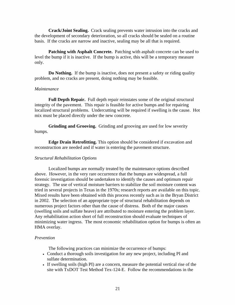
Crack/Joint Sealing. Crack sealing prevents water intrusion into the cracks and the development of secondary deterioration, so all cracks should be sealed on a routine basis. If the cracks are narrow and inactive, sealing may be all that is required.
Patching with Asphalt Concrete. Patching with asphalt concrete can be used to level the bump if it is inactive. If the bump is active, this will be a temporary measure only.
Do Nothing. If the bump is inactive, does not present a safety or riding quality problem, and no cracks are present, doing nothing may be feasible. Maintenance
Full Depth Repair. Full depth repair reinstates some of the original structural integrity of the pavement. This repair is feasible for active bumps and for repairing localized structural problems. Undercutting will be required if swelling is the cause. Hot mix must be placed directly under the new concrete.
Grinding and Grooving. Grinding and grooving are used for low severity bumps.
Edge Drain Retrofitting. This option should be considered if excavation and reconstruction are needed and if water is entering the pavement structure. Structural Rehabilitation Options
Localized bumps are normally treated by the maintenance options described above. However, in the very rare occurrence that the bumps are widespread, a full forensic investigation should be undertaken to identify the causes and optimum repair strategy. The use of vertical moisture barriers to stabilize the soil moisture content was tried in several projects in Texas in the 1970s; research reports are available on this topic. Mixed results have been obtained with this process recently such as in the Bryan District in 2002. The selection of an appropriate type of structural rehabilitation depends on numerous project factors other than the cause of distress. Both of the major causes (swelling soils and sulfate heave) are attributed to moisture entering the problem layer. Any rehabilitation action short of full reconstruction should evaluate techniques of minimizing water ingress. The most economic rehabilitation option for bumps is often an HMA overlay. Prevention
The following practices can minimize the occurrence of bumps: • Conduct a thorough soils investigation for any new project, including PI and
sulfate determination. • If swelling soils (high PI) are a concern, measure the potential vertical rise of the
site with TxDOT Test Method Tex-124-E. Follow the recommendations in the
22
online design guide for selecting undercutting and select fill requirements. Follow the recommendations of the study.
• If sulfates are a concern, follow the recommendations of TxDOT Stabilization Design Guide. Guidelines on these options are given in TxDOT’s online design manual.
Crack Spalling
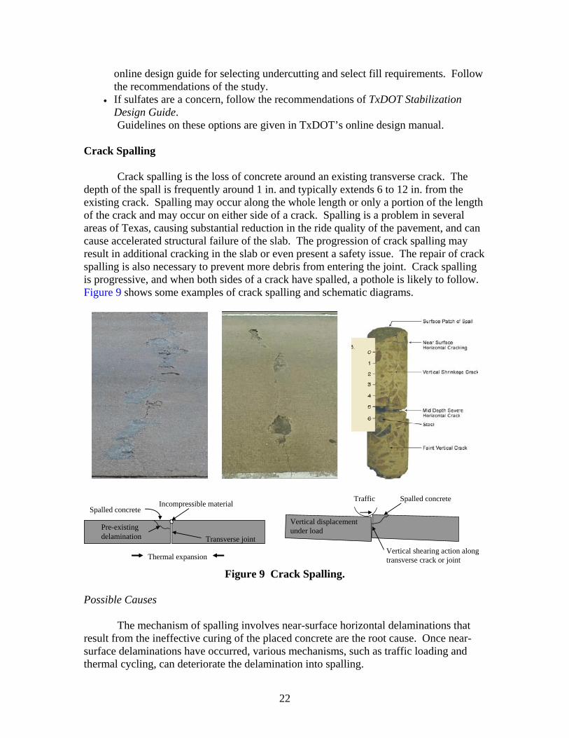
Crack spalling is the loss of concrete around an existing transverse crack. The depth of the spall is frequently around 1 in. and typically extends 6 to 12 in. from the existing crack. Spalling may occur along the whole length or only a portion of the length of the crack and may occur on either side of a crack. Spalling is a problem in several areas of Texas, causing substantial reduction in the ride quality of the pavement, and can cause accelerated structural failure of the slab. The progression of crack spalling may result in additional cracking in the slab or even present a safety issue. The repair of crack spalling is also necessary to prevent more debris from entering the joint. Crack spalling is progressive, and when both sides of a crack have spalled, a pothole is likely to follow. Figure 9 shows some examples of crack spalling and schematic diagrams.
Thermal expansion
Transverse joint
Incompressible material
Pre-existing delamination
Spalled concrete
Traffic Spalled concrete
Vertical shearing action along transverse crack or joint
Vertical displacement under load
Figure 9 Crack Spalling.
Possible Causes
The mechanism of spalling involves near-surface horizontal delaminations that result from the ineffective curing of the placed concrete are the root cause. Once near-surface delaminations have occurred, various mechanisms, such as traffic loading and thermal cycling, can deteriorate the delamination into spalling.
23
In the Houston District, severe spalling is often associated with the use of gravel aggregates in continuously reinforced concrete pavement. Severe spalling is rarely a problem with pavements constructed with limestone aggregates. It is suspected that the loss of bond between the concrete and gravel aggregates expedite spalling if horizontal delaminations are already present. The most common cause of crack spalling is the ineffective curing of concrete that leads to near-surface horizontal delaminations. Hot weather and high wind that cause high evaporation are known to negatively affect the curing process and cause near-surface delaminations. Field Investigation
Use a sounding hammer or ground-coupled GPR to identify the extent and severity of spalling. If possible, determine the weather conditions during paving operations (i.e., high wind speed and/or high temperatures). Refer to the nomograph from the Portland Cement Association manual titled “Design and Control of Concrete Mixtures” to determine the potential evaporation rate for the concrete. Laboratory Investigation
The following laboratory investigations are recommended: • Identify the type and source of the aggregates used in the concrete. Determine the
prior history of the aggregate source. • Obtain the construction date and review weather records during construction to
check if the weather may have affected curing. The ratio of wind speed to relative humidity is a good measure of delamination potential (i.e., > 30-40 mph).
• Review curing methods and curing compounds used during construction. Contact TxDOT’s Rigid Pavement and Concrete Materials Branch of the Materials and Pavements Section in the Construction Division to determine if the curing compound has been effective in the past.
• If delaminations are found at lower depths in spalled sections of concrete, additional testing may be required, but these deeper delaminations are typically not a concern unless they coincide with the longitudinal steel.
Repair Strategies
Little can be done to retard the development of spalling once it initiates. It is, therefore, feasible to leave the distress until it starts affecting ride quality and then repair it. Routine Maintenance
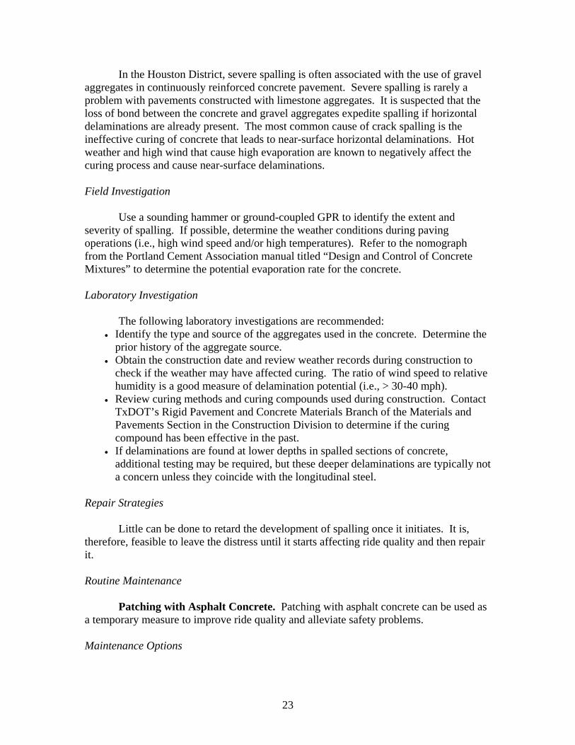
Patching with Asphalt Concrete. Patching with asphalt concrete can be used as a temporary measure to improve ride quality and alleviate safety problems. Maintenance Options
24
Full Depth Repair. Full depth repair reinstates the structural integrity of the pavement. This repair is feasible for deep spalling, which is greater than 1/3 the thickness of the slab.
Partial Depth Repair. This repair is feasible if the spalling is less than 1/3 the
thickness of the slab. Studies are underway to determine the most effective spall repair material. Prevention
Proper curing and techniques and careful selection of the aggregate can minimize the occurrence of spalling. Faulting
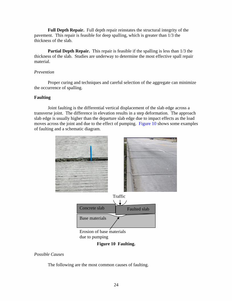
Joint faulting is the differential vertical displacement of the slab edge across a transverse joint. The difference in elevation results in a step deformation. The approach slab edge is usually higher than the departure slab edge due to impact effects as the load moves across the joint and due to the effect of pumping. Figure 10 shows some examples of faulting and a schematic diagram.
Traffic
Base materials
Erosion of base materials due to pumping
Concrete slab Faulted slab
Figure 10 Faulting.
Possible Causes
The following are the most common causes of faulting.
25
Erosion of Support by Pumping - Water enters a joint subjected to traffic action and the vertical slab movement under load propels the water back and forth under the slab in a pumping action, which erodes the underlying slab support, creates a void under the departure slab and a build up of fines under the approach slab. Faulting will then be the result. Erosion used to be a major problem for slabs built on untreated select fill bases or with some cement treated base materials. It is not too common with new pavements built on non erodible bases but it is common on jointed concrete pavement built before 1980.
Lack of Adequate Load Transfer. Faulting frequently occurs on jointed pavements where an inadequate load transfer system is used to transfer load from one slab to another. An inadequate load transfer system may be caused by the use of no load transfer steel or the use of inadequate steel. The high load stress, which is not distributed to the adjacent slab, leads to high deflections of the slab under loading. The high deflections result in more rapid settlement and degradation of the support layers. Traffic action and free moisture under the slab accelerate the development of faulting in this manner. Support layers that are susceptible to moisture can accelerate the development of faulting if free moisture is available beneath the pavement. Field Investigation
Guidelines for the identification of the most common cause of distress are as follows:
• Conduct load transfer deflection testing across the faulted joints. This can be done using the FWD or the rolling dynamic deflectometer (RDD).
• Conduct a non-contact GPR survey to detect voids and moisture beneath the joints. • Conduct a ground-coupled GPR survey to determine if the joints contain any load
transfer devices. This is often necessary with older pavements where as-built information is not available. The presence of joint steel can easily be detected with a 1.5 GHz ground-coupled survey.
• Conduct a DCP survey to identify the quality of the underlying material near the faulted joint.
• Use a dry drill to gain access to the base. Check in the drilled hole for the presence of voids or moisture directly beneath the slab.
Repair Strategies
Most localized faulting problems can be repaired by using maintenance techniques, such as slab stabilization, grinding, and dowel bar retrofitting. Maintenance techniques may be ineffective on pavements that have widespread faulting problems that originate from the use of moisture-susceptible support layers and/or inappropriate load transfer design. In these cases, structural rehabilitation may be the only solution.
An understanding of the future deterioration of the pavement and all other pertinent factors should form the basis of developing several feasible repair alternatives. The preferred repair option should then be selected from this list of feasible alternatives. Typical routine maintenance, maintenance, and structural rehabilitation options for
26
concrete pavements are provided below. Repair alternatives can consist of any combination of these options and other repair methods that are not listed. Routine Maintenance
Crack/Joint Sealing. Joint sealing prevents water intrusion into the underlying layers at the joint. Since free moisture accelerates the development of faulting, joints should be maintained on a regular basis, particularly in high rainfall areas and on pavements with moisture-susceptible support layers.
Do Nothing. Faulting creates a ride quality problem to the traveling public. In
cases where the faulting is of low severity (< 0.13 in.) and the pavement has aged, little benefit can be derived from repairing the faulting. In these cases, the do nothing alternative may be a viable option until the faulting progresses to a higher level of severity where it has a greater effect on ride quality. Maintenance Options
Full Depth Repair. Full depth repair of the pavement joint can reinstate the support layers at the joint and replace the joint load transfer system. This treatment may be feasible if the support layers have degraded as a result of pumping and the joint load transfer system is inadequate.
Dowel Bar Retrofit. Dowel bar retrofit may be used to retrofit a load transfer system when an inadequate system exists. Many old pavements were built without steel load transfer systems, where the only load transfer is by means of aggregate interlock. With the action of traffic over time, the aggregate interlock wears out so the load transfer diminishes and faulting occurs. Dowel bar retrofit is most feasible on pavements with poor load transfer systems but with little degradation of the underlying layers or voids beneath the joint. After retrofitting, the slab is usually ground to give a good ride.
Slab Stabilization. Slab stabilization can be used in conjunction with dowel bar retrofit to fill voids beneath the pavement.
Slab Jacking. Slab jacking with grouts of various types has been tried in several places around Texas. Slabs can be raised, but this technique was in some cases found to be only a temporary solution. In some cases lifting the corner of slabs has resulted in future problems at mid-slab. This method is not recommended.
Grinding and Grooving. Grinding can be used to improve ride quality by eliminating the fault. However, this action does not treat the cause of the distress and is best used in conjunction with other treatments, such as dowel bar retrofitting (DBR). Experience has shown that without additional treatments such as DBR, the faulted section will reappear in less than 2 years if only grinding is used.
27
Structural Rehabilitation Options The selection of an appropriate type of structural rehabilitation depends on
numerous project factors other than the cause of distress. Any of the following structural rehabilitation options may be appropriate and should be evaluated on a case by case basis:
• retrofit doweling, • thin-bonded concrete overlay, • unbonded concrete overlay, • undersealing, • rubblization and HMA overlay, • crack and seat with flexible base overlay and HMA overlay, and • reconstruction .
Prevention
The following practices can minimize the occurrence of faulting: • Maintain joint seals to prevent water infiltration at the joint. • Use subbases that are not erosion susceptible. • Provide adequate drainage to prevent water infiltration. • Provide sufficient load transfer devices.
Joint Spalling
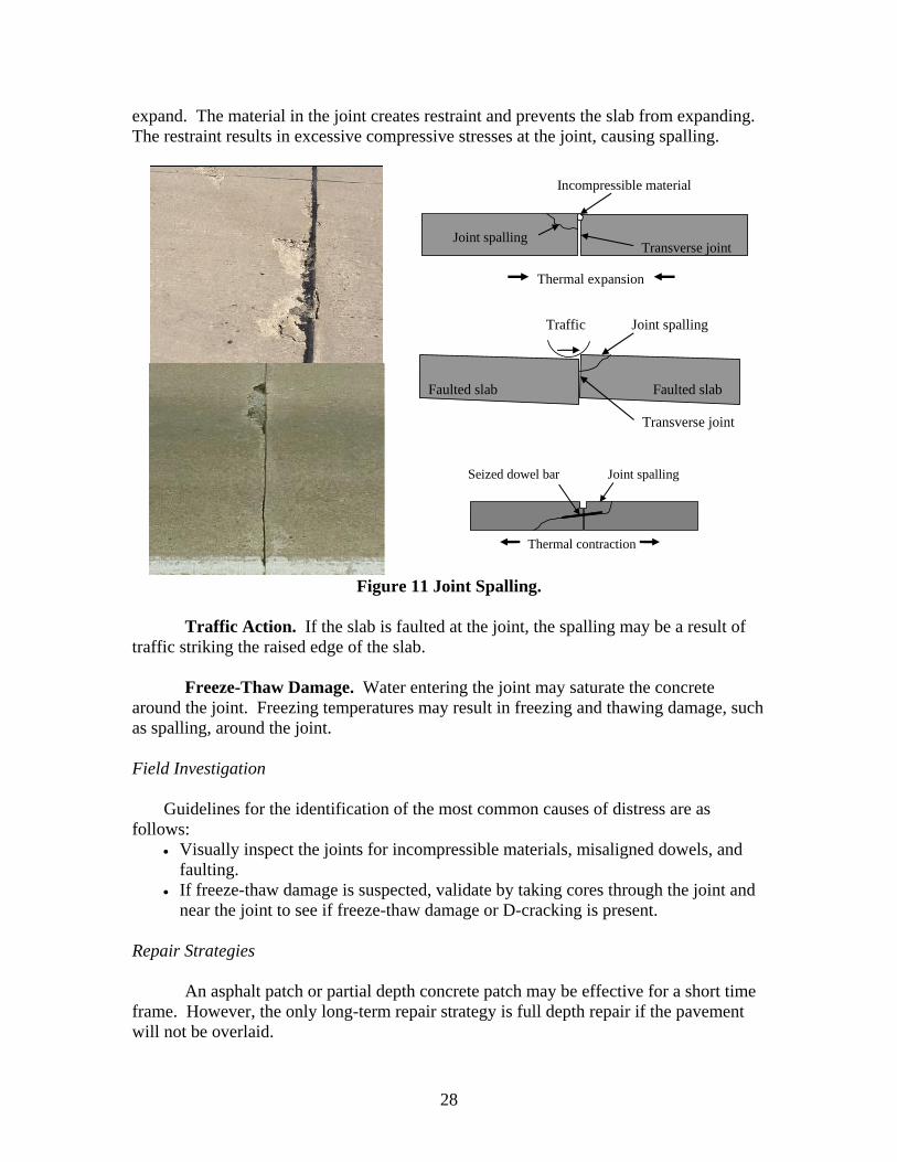
Joint spalling is the chipping of the concrete slab at the edges of longitudinal or transverse joints. The spalling may occur along the whole length or only a portion of the length of the joint and may occur on either side of the joint. Joint spalling is due to excessive local pressure at the joint. This pressure may be due to a combination of traffic action, thermal expansion, and/or steel corrosion. After both sides of a joint have spalled, the spalling may progress into a pothole.
Joint spalling will reduce the riding quality of the pavement. The progression of joint spalling may result in additional cracking in the slab or even present a safety issue. The repair of joint spalling is also necessary to prevent more debris from entering the joint. Figure 11shows an example of joint spalling and schematic diagrams. Possible Causes
The following are the most common causes of spalling.
Improperly Designed or Constructed Joints. Certain joint designs have exhibited spalling. In particular, the “wrinkled tin” transverse joint design has resulted in spalling.
Incompressible Materials in the Joints. Wide joints allow incompressible material to enter. In warmer weather, the increasing temperatures cause the slab to
28
expand. The material in the joint creates restraint and prevents the slab from expanding. The restraint results in excessive compressive stresses at the joint, causing spalling.
Thermal expansion
Transverse joint
Incompressible material
Joint spalling
Traffic Joint spalling
Transverse joint
Faulted slab Faulted slab
Seized dowel bar Joint spalling
Thermal contraction
Figure 11 Joint Spalling.
Traffic Action. If the slab is faulted at the joint, the spalling may be a result of traffic striking the raised edge of the slab.
Freeze-Thaw Damage. Water entering the joint may saturate the concrete around the joint. Freezing temperatures may result in freezing and thawing damage, such as spalling, around the joint. Field Investigation
Guidelines for the identification of the most common causes of distress are as follows:
• Visually inspect the joints for incompressible materials, misaligned dowels, and faulting.
• If freeze-thaw damage is suspected, validate by taking cores through the joint and near the joint to see if freeze-thaw damage or D-cracking is present.
Repair Strategies
An asphalt patch or partial depth concrete patch may be effective for a short time frame. However, the only long-term repair strategy is full depth repair if the pavement will not be overlaid.

29
Routine Maintenance
Patching with Asphalt Concrete. Patching with asphalt concrete can be used as a temporary measure to improve ride quality and alleviate safety problems. Little can be done to retard the development of spalling once it initiates. It is therefore feasible to leave the distress until it starts affecting ride quality and then repair it. Maintenance Options
Full Depth Repair. Full depth repair reinstates the structural integrity of the pavement. This repair is feasible for deep spalling, which is greater than 1/3 the thickness of the slab.
Partial Depth Repair. This repair is feasible if the spalling is less than 1/3 the thickness of the slab. Studies are underway to determine the most effective spall repair material. Prevention
The following practices can minimize the occurrence of joint spalling: • Frequent observation of pavement sections can provide early identification of
debris in the joints. Clean and re-seal joints if incompressible material has entered the joints.
• Be sure that the dowels are aligned properly during construction. • Use proper joint designs as indicated in the current TxDOT standards.
Settlement
Settlement is the downward vertical movement of the pavement from its original constructed longitudinal profile. The settled pavement introduces roughness into the pavement section and in extreme cases can be a safety concern. Secondary issues may be slab cracking and the ponding of water. It is often difficult to discriminate between settlements (downward) and bumps (upward). Bumps are discussed elsewhere in this section.
The main problem with settlement is the increase in pavement roughness. Once a pavement settles, severe pitch and roll may occur, causing the driver some discomfort. Ponding may also be a result of settlement. Ponding creates a safety concern since hydroplaning may become a problem. Settlement may also cause slab cracking due to the increased bending of the slab. Figure 12 shows an example of settlement and a schematic diagram.
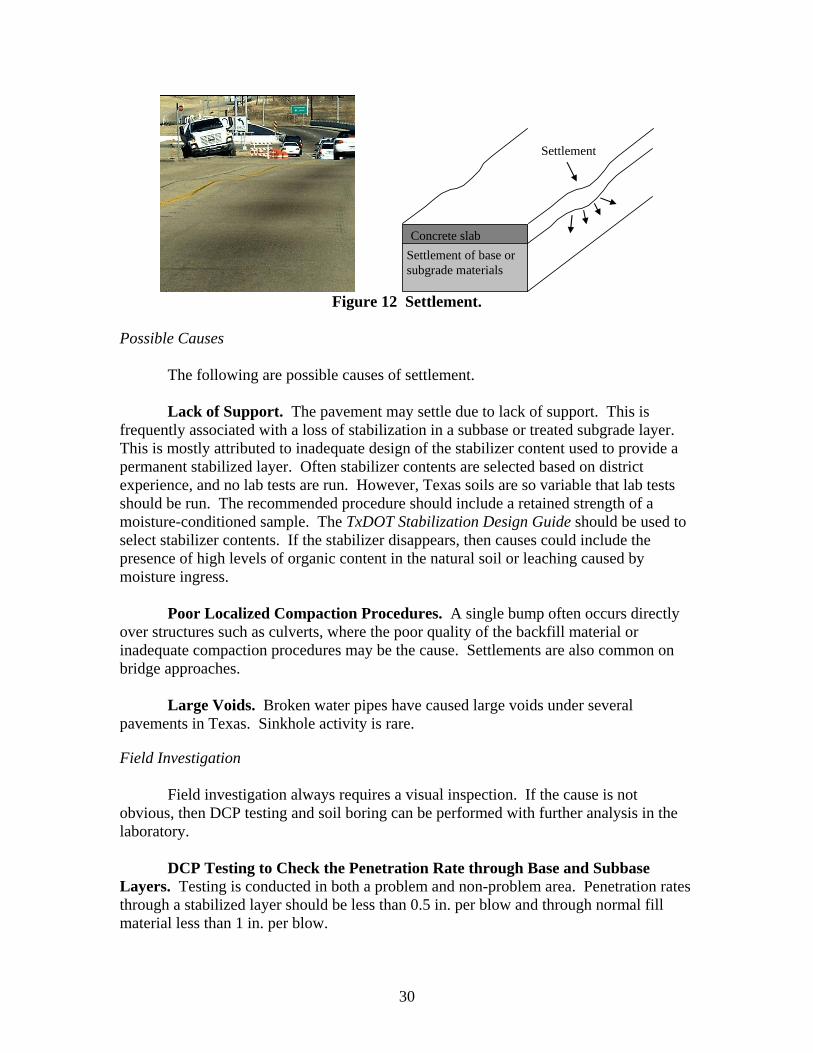
30
Settlement of base or subgrade materials
Concrete slab
Settlement
Figure 12 Settlement.
Possible Causes
The following are possible causes of settlement.
Lack of Support. The pavement may settle due to lack of support. This is frequently associated with a loss of stabilization in a subbase or treated subgrade layer. This is mostly attributed to inadequate design of the stabilizer content used to provide a permanent stabilized layer. Often stabilizer contents are selected based on district experience, and no lab tests are run. However, Texas soils are so variable that lab tests should be run. The recommended procedure should include a retained strength of a moisture-conditioned sample. The TxDOT Stabilization Design Guide should be used to select stabilizer contents. If the stabilizer disappears, then causes could include the presence of high levels of organic content in the natural soil or leaching caused by moisture ingress.
Poor Localized Compaction Procedures. A single bump often occurs directly over structures such as culverts, where the poor quality of the backfill material or inadequate compaction procedures may be the cause. Settlements are also common on bridge approaches.
Large Voids. Broken water pipes have caused large voids under several pavements in Texas. Sinkhole activity is rare.
Field Investigation
Field investigation always requires a visual inspection. If the cause is not obvious, then DCP testing and soil boring can be performed with further analysis in the laboratory.
DCP Testing to Check the Penetration Rate through Base and Subbase Layers. Testing is conducted in both a problem and non-problem area. Penetration rates through a stabilized layer should be less than 0.5 in. per blow and through normal fill material less than 1 in. per blow.
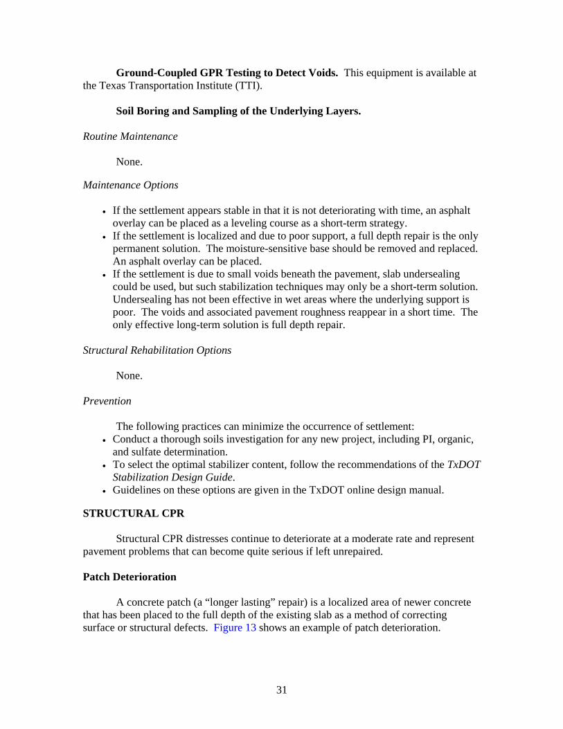
31
Ground-Coupled GPR Testing to Detect Voids. This equipment is available at the Texas Transportation Institute (TTI).
Soil Boring and Sampling of the Underlying Layers. Routine Maintenance
None. Maintenance Options
• If the settlement appears stable in that it is not deteriorating with time, an asphalt overlay can be placed as a leveling course as a short-term strategy.
• If the settlement is localized and due to poor support, a full depth repair is the only permanent solution. The moisture-sensitive base should be removed and replaced. An asphalt overlay can be placed.
• If the settlement is due to small voids beneath the pavement, slab undersealing could be used, but such stabilization techniques may only be a short-term solution. Undersealing has not been effective in wet areas where the underlying support is poor. The voids and associated pavement roughness reappear in a short time. The only effective long-term solution is full depth repair.
Structural Rehabilitation Options
None. Prevention
The following practices can minimize the occurrence of settlement: • Conduct a thorough soils investigation for any new project, including PI, organic,
and sulfate determination. • To select the optimal stabilizer content, follow the recommendations of the TxDOT
Stabilization Design Guide. • Guidelines on these options are given in the TxDOT online design manual.
STRUCTURAL CPR
Structural CPR distresses continue to deteriorate at a moderate rate and represent pavement problems that can become quite serious if left unrepaired. Patch Deterioration
A concrete patch (a “longer lasting” repair) is a localized area of newer concrete that has been placed to the full depth of the existing slab as a method of correcting surface or structural defects. Figure 13 shows an example of patch deterioration.
32
Figure 13 Patch Deterioration.
Possible Causes
Patches are intended to repair bad areas in an existing pavement; however, many times the patch itself deteriorates quickly or causes nearby disintegration. The causes for disintegration of the patch include:
• Poor compaction of the base/subgrade under the patch, usually caused by wet areas not being dried properly, difficulties in compacting in the small space, construction activities in the patched area, and many others.
• In some cases, the concrete patching material itself may be substandard due to the relatively small amounts of materials being used, the length of time between the time the material is batched and the time it is finally placed, low air and pavement temperatures at the time of placement, segregation of the material, opening the pavement to traffic before adequate strength has been reached, and many others. The causes for disintegration of the surrounding area include:
• construction practices when installing load transfer devices, • de-compaction of the area under the adjacent slab during repair operations, • spalling (causes will be the same as discussed under spalling), and • others.
Field Investigation
Typically a GPR investigation of the patched and nearby areas to confirm water under the slab and in the base is conducted, along with FWD data collection for the slabs and adjacent areas to confirm load transfer. Repair Strategies
An asphalt patch or partial depth concrete patch may be effective for a short time frame. However, the only long-term repair strategy is full depth repair if the pavement will not be overlaid. In some cases, the patches are a substantial source of roughness, which must be corrected to improve the pavement.
33
Routine Maintenance
Patching with Asphalt Concrete. Patching with asphalt concrete can be used as a temporary measure to improve ride quality and alleviate safety problems. Little can be done to retard the development of spalling once it initiates. It is, therefore, feasible to leave the distress until it starts affecting ride quality and then repair it. Maintenance Options
Full Depth Repair. Full depth repair reinstates the structural integrity of the pavement. This repair is feasible for deep spalling, which is greater than 1/3 the thickness of the slab.
Partial Depth Repair. This repair is feasible if the spalling is less than 1/3 the thickness of the slab. Studies are underway to determine the most effective spall repair material.
Diamond Grinding. Diamond grinding removes a thin layer at the surface of hardened PCC pavement using closely spaced diamond blades. This repair is feasible if the aggregates are not hard. Hard aggregates reduce production rates, increase cost, and may contribute to excessive spalling.
HMA Overlay. An overlay covers up all of the patches, provides a smoother surface, and increases the pavement score. For a pavement with a substantial number of patches (> 10/mi), an overlay is often the only technique that will improve the pavement management information system (PMIS) score. Prevention
Use of proper construction and patching techniques will minimize the
deterioration of the patch and surrounding areas.
Pumping
Pumping is the expulsion of water and silts, sands, or clays from joints or cracks when load is applied to the pavement. If water enters the joint or crack, it may erode the underlying layers of the pavement. When load is applied to the approach slab, the water will propel underneath the departure slab. When the load moves to the departure slab, the water will propel back underneath the approach slab. The constant movement of water back and forth will erode the base layers and create cavities underneath the pavement. The cavities may also create slab rocking where the edge of the slab moves vertically when load is applied to an undowelled pavement. Pumping of the pavement can be considered a major distress. After pumping is observed, failure of the pavement is not far behind. Figure 14 shows an example of pumping.
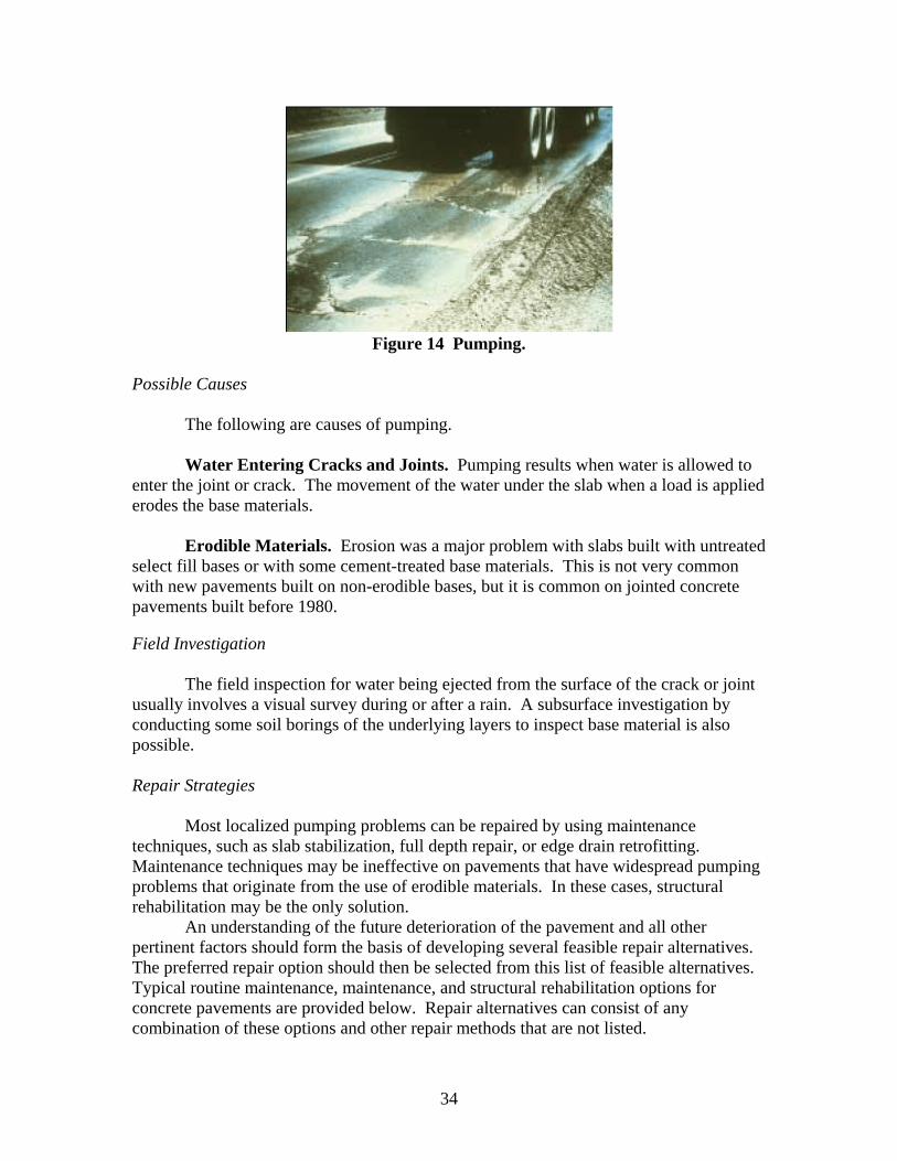
34
Figure 14 Pumping.
Possible Causes
The following are causes of pumping.
Water Entering Cracks and Joints. Pumping results when water is allowed to enter the joint or crack. The movement of the water under the slab when a load is applied erodes the base materials.
Erodible Materials. Erosion was a major problem with slabs built with untreated
select fill bases or with some cement-treated base materials. This is not very common with new pavements built on non-erodible bases, but it is common on jointed concrete pavements built before 1980. Field Investigation
The field inspection for water being ejected from the surface of the crack or joint usually involves a visual survey during or after a rain. A subsurface investigation by conducting some soil borings of the underlying layers to inspect base material is also possible. Repair Strategies
Most localized pumping problems can be repaired by using maintenance techniques, such as slab stabilization, full depth repair, or edge drain retrofitting. Maintenance techniques may be ineffective on pavements that have widespread pumping problems that originate from the use of erodible materials. In these cases, structural rehabilitation may be the only solution.
An understanding of the future deterioration of the pavement and all other pertinent factors should form the basis of developing several feasible repair alternatives. The preferred repair option should then be selected from this list of feasible alternatives. Typical routine maintenance, maintenance, and structural rehabilitation options for concrete pavements are provided below. Repair alternatives can consist of any combination of these options and other repair methods that are not listed.
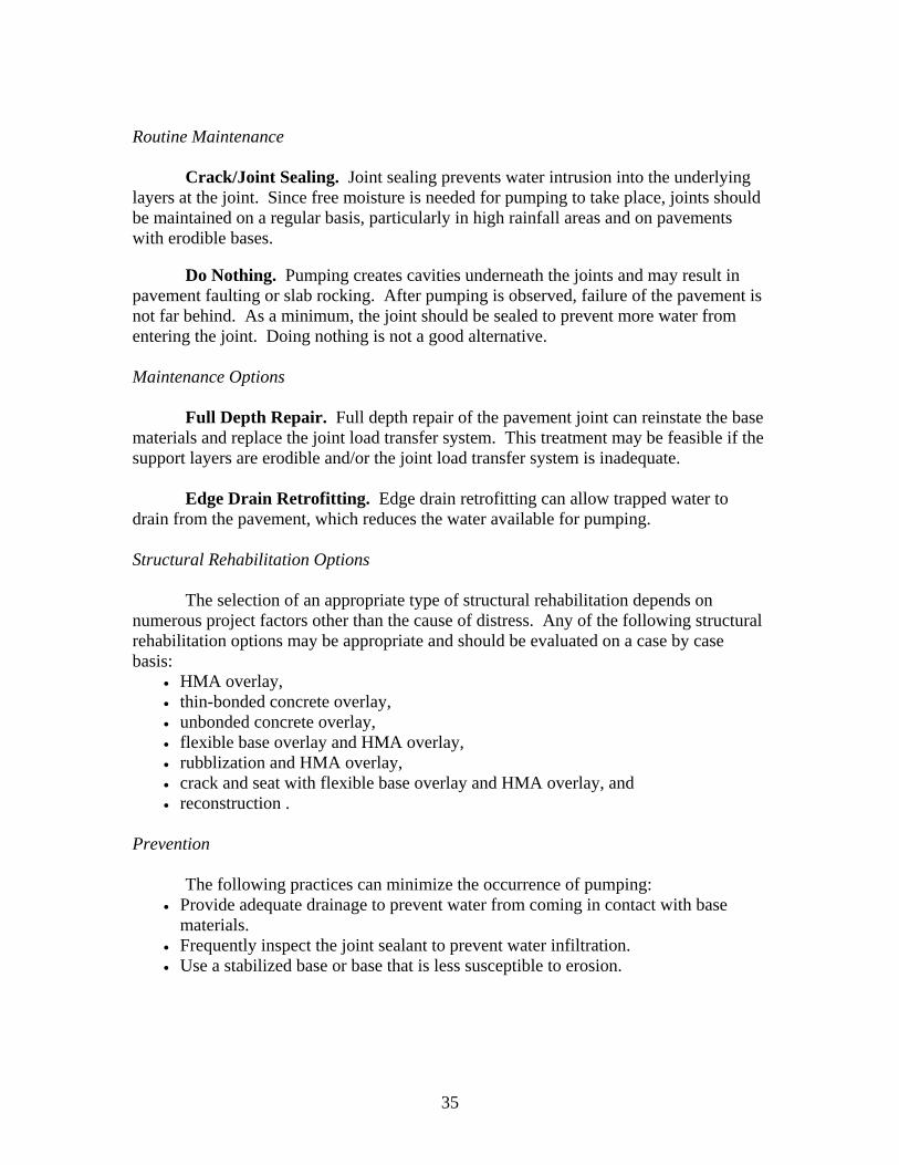
35
Routine Maintenance
Crack/Joint Sealing. Joint sealing prevents water intrusion into the underlying layers at the joint. Since free moisture is needed for pumping to take place, joints should be maintained on a regular basis, particularly in high rainfall areas and on pavements with erodible bases.
Do Nothing. Pumping creates cavities underneath the joints and may result in
pavement faulting or slab rocking. After pumping is observed, failure of the pavement is not far behind. As a minimum, the joint should be sealed to prevent more water from entering the joint. Doing nothing is not a good alternative. Maintenance Options
Full Depth Repair. Full depth repair of the pavement joint can reinstate the base materials and replace the joint load transfer system. This treatment may be feasible if the support layers are erodible and/or the joint load transfer system is inadequate.
Edge Drain Retrofitting. Edge drain retrofitting can allow trapped water to drain from the pavement, which reduces the water available for pumping. Structural Rehabilitation Options
The selection of an appropriate type of structural rehabilitation depends on numerous project factors other than the cause of distress. Any of the following structural rehabilitation options may be appropriate and should be evaluated on a case by case basis:
• HMA overlay, • thin-bonded concrete overlay, • unbonded concrete overlay, • flexible base overlay and HMA overlay, • rubblization and HMA overlay, • crack and seat with flexible base overlay and HMA overlay, and • reconstruction .
Prevention
The following practices can minimize the occurrence of pumping: • Provide adequate drainage to prevent water from coming in contact with base
materials. • Frequently inspect the joint sealant to prevent water infiltration. • Use a stabilized base or base that is less susceptible to erosion.
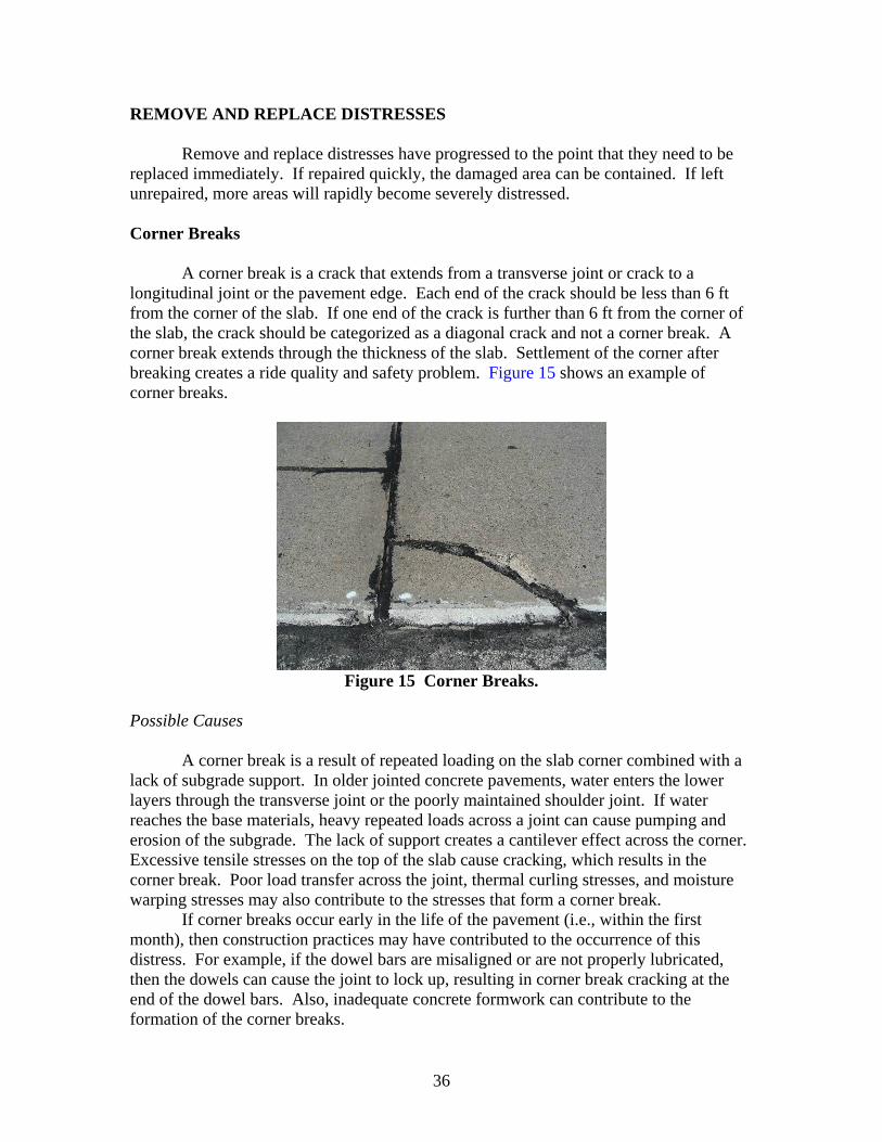
36
REMOVE AND REPLACE DISTRESSES
Remove and replace distresses have progressed to the point that they need to be replaced immediately. If repaired quickly, the damaged area can be contained. If left unrepaired, more areas will rapidly become severely distressed. Corner Breaks
A corner break is a crack that extends from a transverse joint or crack to a longitudinal joint or the pavement edge. Each end of the crack should be less than 6 ft from the corner of the slab. If one end of the crack is further than 6 ft from the corner of the slab, the crack should be categorized as a diagonal crack and not a corner break. A corner break extends through the thickness of the slab. Settlement of the corner after breaking creates a ride quality and safety problem. Figure 15 shows an example of corner breaks.
Figure 15 Corner Breaks.
Possible Causes
A corner break is a result of repeated loading on the slab corner combined with a lack of subgrade support. In older jointed concrete pavements, water enters the lower layers through the transverse joint or the poorly maintained shoulder joint. If water reaches the base materials, heavy repeated loads across a joint can cause pumping and erosion of the subgrade. The lack of support creates a cantilever effect across the corner. Excessive tensile stresses on the top of the slab cause cracking, which results in the corner break. Poor load transfer across the joint, thermal curling stresses, and moisture warping stresses may also contribute to the stresses that form a corner break.
If corner breaks occur early in the life of the pavement (i.e., within the first month), then construction practices may have contributed to the occurrence of this distress. For example, if the dowel bars are misaligned or are not properly lubricated, then the dowels can cause the joint to lock up, resulting in corner break cracking at the end of the dowel bars. Also, inadequate concrete formwork can contribute to the formation of the corner breaks.
37
Field Investigation
Poor support is the primary cause of corner breaks, so the quality of the base material should be validated by taking cores of the base material for laboratory testing. In order to investigate the amount of subslab material that will need to be replaced, it is recommended that a DCP test be conducted to identify if substantial undercutting will be needed to provide a stable support layer. Laboratory Investigation
Laboratory investigation is not normally required. However, if the cause of the problem is a loss of stabilization from the base layer, then the TxDOT Stabilization Design Guide should be consulted. Tests could be undertaken to measure the moisture susceptibility of any proposed base layer. Repair Strategies
The only maintenance technique that is effective for the repair of corner breaks is full depth repair. If corner breaks are widespread, rehabilitation of the pavement should be considered. Routine Maintenance
Crack/Joint Sealing. Joint sealing may prevent moisture from penetrating the subgrade materials and reduce the effects of pumping and erosion, which lead to corner breaks. Crack sealing of the corner crack does little to maintain the corner break. Resealing the longitudinal joint will be critical to slow the development of this distress.
Patching with Asphalt Concrete. Patching with asphalt concrete can be used as a stopgap measure to temporarily improve ride quality. However, such patching may not last very long under traffic loading.
Do Nothing. Once a corner break has occurred, little can be done to retard the further development of the distress. Low severity corner breaks have little effect on safety and ride quality, but the crack allows moisture to penetrate the support layers and accelerates deterioration. Due to the increased rate of deterioration, corner breaks normally need to be maintained fairly soon after occurrence. Maintenance Options
Full Depth Repair. Full depth repair reinstates the structural integrity of the pavement. This repair is feasible for corner breaks.
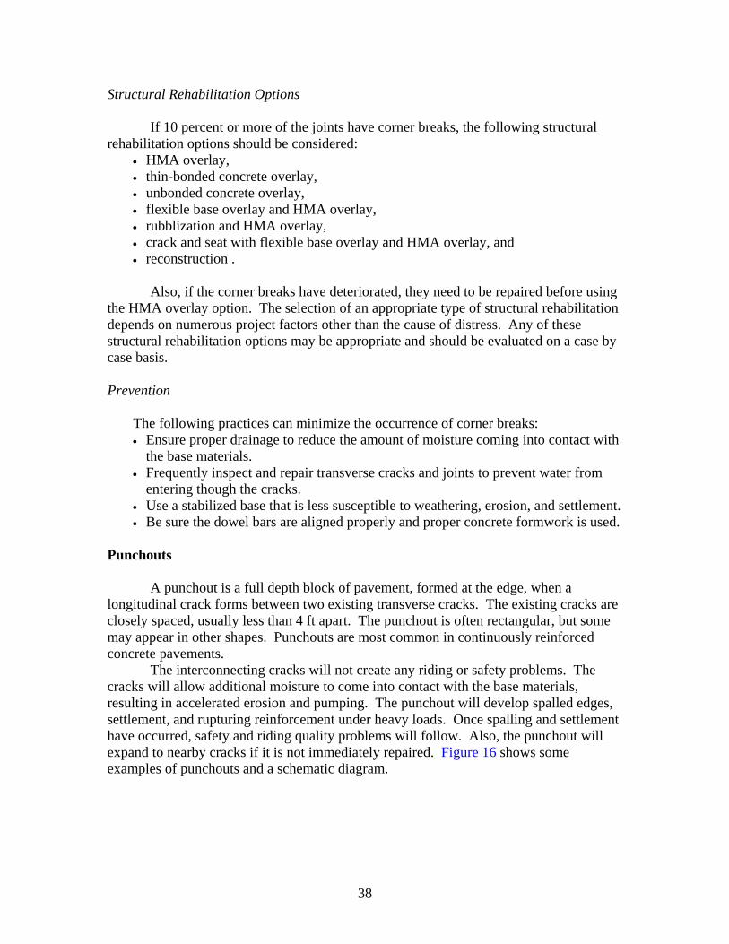
38
Structural Rehabilitation Options
If 10 percent or more of the joints have corner breaks, the following structural rehabilitation options should be considered:
• HMA overlay, • thin-bonded concrete overlay, • unbonded concrete overlay, • flexible base overlay and HMA overlay, • rubblization and HMA overlay, • crack and seat with flexible base overlay and HMA overlay, and • reconstruction .
Also, if the corner breaks have deteriorated, they need to be repaired before using
the HMA overlay option. The selection of an appropriate type of structural rehabilitation depends on numerous project factors other than the cause of distress. Any of these structural rehabilitation options may be appropriate and should be evaluated on a case by case basis. Prevention
The following practices can minimize the occurrence of corner breaks: • Ensure proper drainage to reduce the amount of moisture coming into contact with
the base materials. • Frequently inspect and repair transverse cracks and joints to prevent water from
entering though the cracks. • Use a stabilized base that is less susceptible to weathering, erosion, and settlement. • Be sure the dowel bars are aligned properly and proper concrete formwork is used.
Punchouts
A punchout is a full depth block of pavement, formed at the edge, when a longitudinal crack forms between two existing transverse cracks. The existing cracks are closely spaced, usually less than 4 ft apart. The punchout is often rectangular, but some may appear in other shapes. Punchouts are most common in continuously reinforced concrete pavements.
The interconnecting cracks will not create any riding or safety problems. The cracks will allow additional moisture to come into contact with the base materials, resulting in accelerated erosion and pumping. The punchout will develop spalled edges, settlement, and rupturing reinforcement under heavy loads. Once spalling and settlement have occurred, safety and riding quality problems will follow. Also, the punchout will expand to nearby cracks if it is not immediately repaired. Figure 16 shows some examples of punchouts and a schematic diagram.
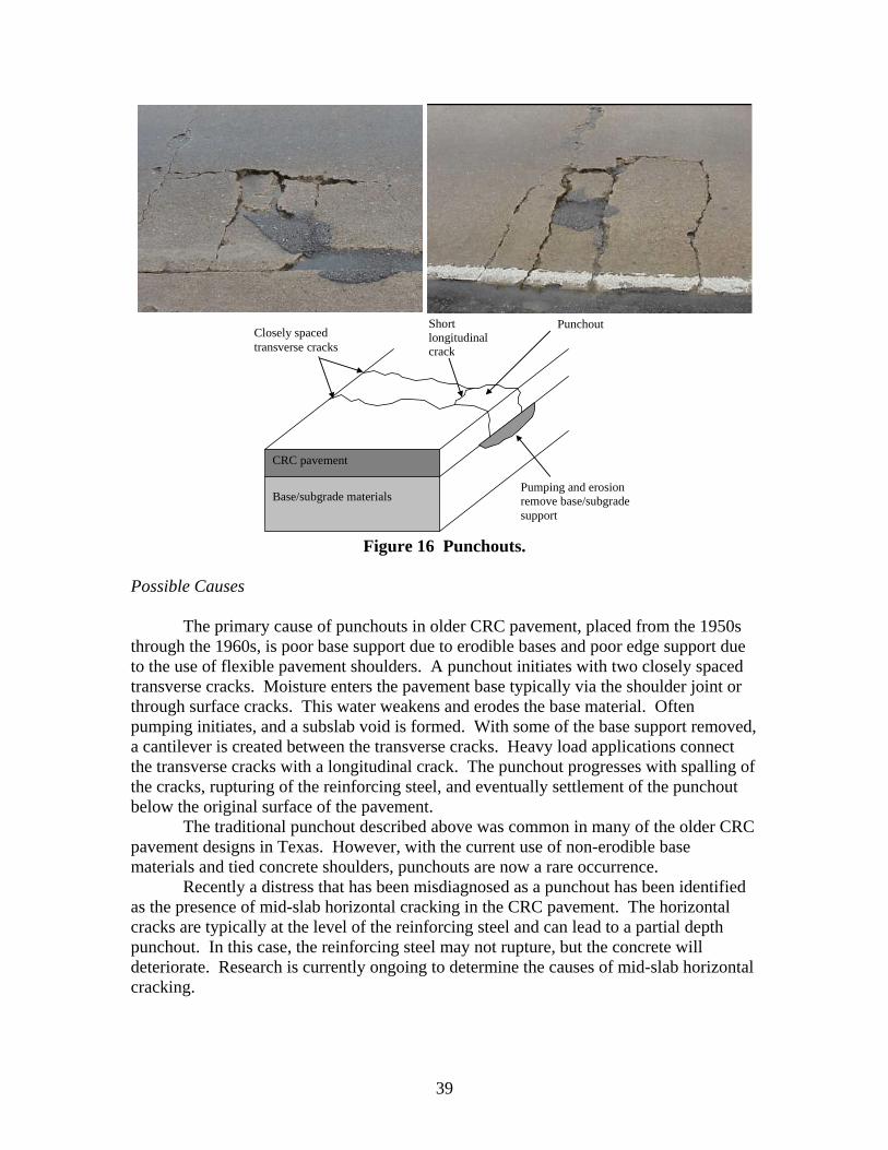
39
Base/subgrade materials
CRC pavement
Pumping and erosion remove base/subgrade support
Punchout Short longitudinal crack
Closely spaced transverse cracks
Figure 16 Punchouts.
Possible Causes
The primary cause of punchouts in older CRC pavement, placed from the 1950s through the 1960s, is poor base support due to erodible bases and poor edge support due to the use of flexible pavement shoulders. A punchout initiates with two closely spaced transverse cracks. Moisture enters the pavement base typically via the shoulder joint or through surface cracks. This water weakens and erodes the base material. Often pumping initiates, and a subslab void is formed. With some of the base support removed, a cantilever is created between the transverse cracks. Heavy load applications connect the transverse cracks with a longitudinal crack. The punchout progresses with spalling of the cracks, rupturing of the reinforcing steel, and eventually settlement of the punchout below the original surface of the pavement.
The traditional punchout described above was common in many of the older CRC pavement designs in Texas. However, with the current use of non-erodible base materials and tied concrete shoulders, punchouts are now a rare occurrence.
Recently a distress that has been misdiagnosed as a punchout has been identified as the presence of mid-slab horizontal cracking in the CRC pavement. The horizontal cracks are typically at the level of the reinforcing steel and can lead to a partial depth punchout. In this case, the reinforcing steel may not rupture, but the concrete will deteriorate. Research is currently ongoing to determine the causes of mid-slab horizontal cracking.
40
Field Investigation
In many cases the cause of the classical punchout is clear, and the repair strategy is a full depth repair. However, if a field investigation is needed, it could include a GPR survey to look for subslab moisture. Samples of the base material can also be removed. In order to investigate the amount of subslab material that will need to be replaced, it is recommended that a DCP test be conducted. This will identify if substantial undercutting is needed to provide a stable support layer. In the case of horizontal cracks, a ground-coupled GPR survey can also be helpful in identifying problems within the slab. Repair Strategies
The only maintenance technique that is effective for the repair of punchouts is full depth repair. If punchouts are widespread, rehabilitation of the pavement should be considered. Routine Maintenance
Crack/Joint Sealing. Crack sealing on reinforced concrete pavements, where cracks are numerous, is not feasible if the concrete has deteriorated. However, crack sealing may be possible if the concrete has not deteriorated (i.e., the cracks are still tightly closed and have not spalled). With CRC pavement with asphalt shoulders it is very important to have a good seal between the shoulders and the concrete main lanes. Preventing water from entering the lower layers will retard the onset of punchouts.
Patching with Asphalt Concrete. Patching with asphalt concrete can be used as a stopgap measure to temporarily improve ride quality. However, asphalt patches may not last very long under traffic loading.
Do Nothing. The nature of punchouts is such that little can be done to retard the development of the distress once it initiates. It is therefore feasible to leave the distress until it starts affecting ride quality and then to repair it. Maintenance Options
Full Depth Repair. Full depth repair reinstates the structural integrity of the pavement. This repair is feasible for punchouts.
Structural Rehabilitation Options
If three or more punchouts per mile per year are occurring, the designer needs to consider the following structural rehabilitation options:
• HMA overlay, • thin-bonded concrete overlay, • unbonded concrete overlay, • flexible base overlay and HMA overlay, • rubblization and HMA overlay,
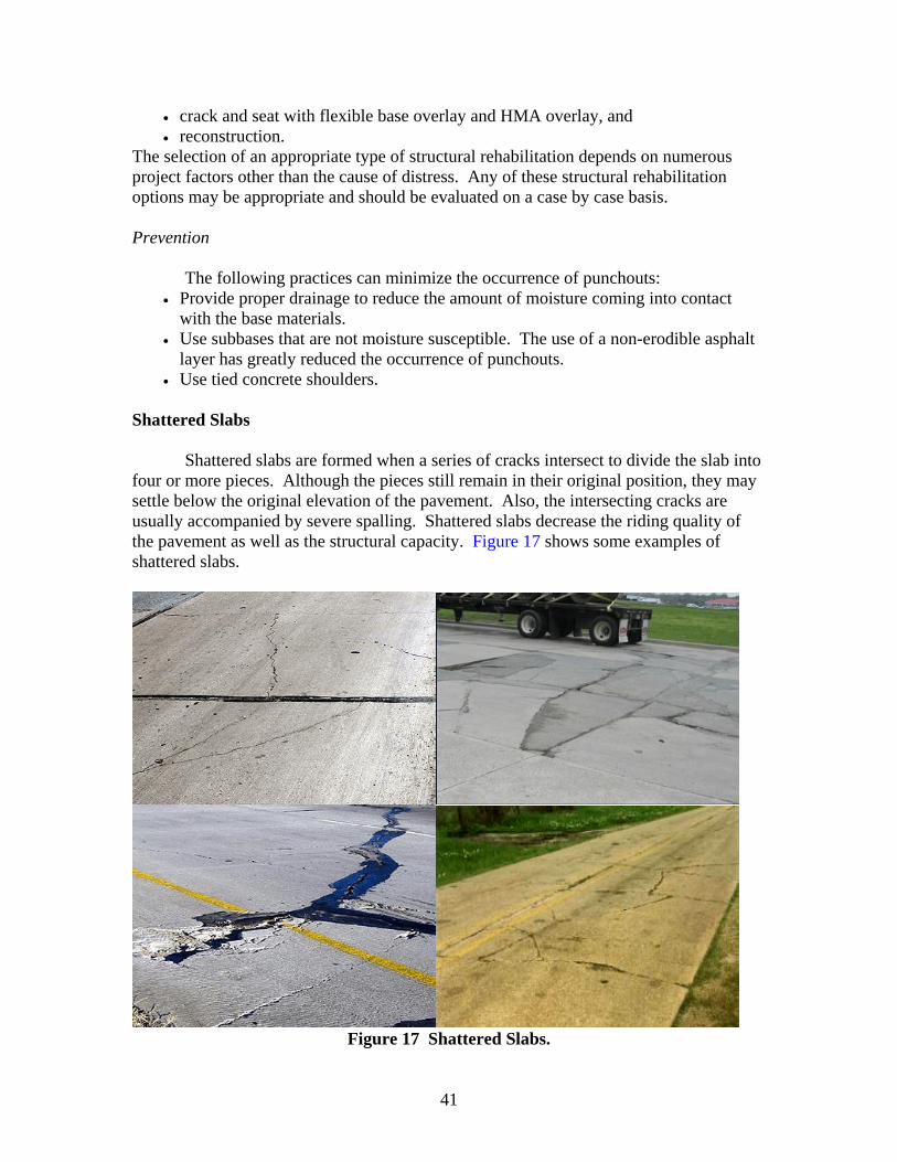
41
• crack and seat with flexible base overlay and HMA overlay, and • reconstruction.
The selection of an appropriate type of structural rehabilitation depends on numerous project factors other than the cause of distress. Any of these structural rehabilitation options may be appropriate and should be evaluated on a case by case basis. Prevention
The following practices can minimize the occurrence of punchouts: • Provide proper drainage to reduce the amount of moisture coming into contact
with the base materials. • Use subbases that are not moisture susceptible. The use of a non-erodible asphalt
layer has greatly reduced the occurrence of punchouts. • Use tied concrete shoulders.
Shattered Slabs
Shattered slabs are formed when a series of cracks intersect to divide the slab into four or more pieces. Although the pieces still remain in their original position, they may settle below the original elevation of the pavement. Also, the intersecting cracks are usually accompanied by severe spalling. Shattered slabs decrease the riding quality of the pavement as well as the structural capacity. Figure 17 shows some examples of shattered slabs.
Figure 17 Shattered Slabs.
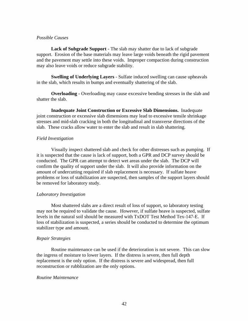
42
Possible Causes
Lack of Subgrade Support - The slab may shatter due to lack of subgrade support. Erosion of the base materials may leave large voids beneath the rigid pavement and the pavement may settle into these voids. Improper compaction during construction may also leave voids or reduce subgrade stability.
Swelling of Underlying Layers - Sulfate induced swelling can cause upheavals in the slab, which results in bumps and eventually shattering of the slab.
Overloading - Overloading may cause excessive bending stresses in the slab and shatter the slab.
Inadequate Joint Construction or Excessive Slab Dimensions. Inadequate joint construction or excessive slab dimensions may lead to excessive tensile shrinkage stresses and mid-slab cracking in both the longitudinal and transverse directions of the slab. These cracks allow water to enter the slab and result in slab shattering. Field Investigation
Visually inspect shattered slab and check for other distresses such as pumping. If it is suspected that the cause is lack of support, both a GPR and DCP survey should be conducted. The GPR can attempt to detect wet areas under the slab. The DCP will confirm the quality of support under the slab. It will also provide information on the amount of undercutting required if slab replacement is necessary. If sulfate heave problems or loss of stabilization are suspected, then samples of the support layers should be removed for laboratory study. Laboratory Investigation
Most shattered slabs are a direct result of loss of support, so laboratory testing may not be required to validate the cause. However, if sulfate heave is suspected, sulfate levels in the natural soil should be measured with TxDOT Test Method Tex-147-E. If loss of stabilization is suspected, a series should be conducted to determine the optimum stabilizer type and amount.
Repair Strategies
Routine maintenance can be used if the deterioration is not severe. This can slow the ingress of moisture to lower layers. If the distress is severe, then full depth replacement is the only option. If the distress is severe and widespread, then full reconstruction or rubblization are the only options. Routine Maintenance
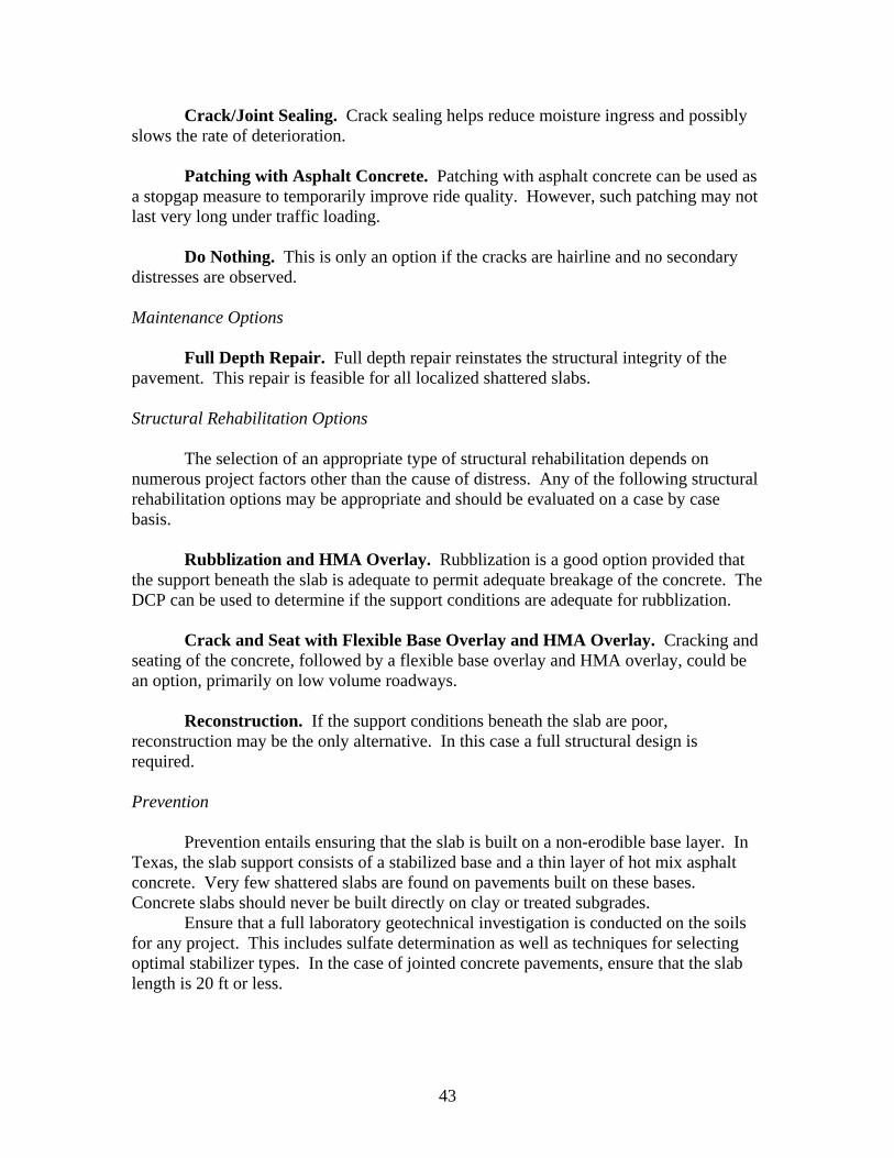
43
Crack/Joint Sealing. Crack sealing helps reduce moisture ingress and possibly slows the rate of deterioration.
Patching with Asphalt Concrete. Patching with asphalt concrete can be used as a stopgap measure to temporarily improve ride quality. However, such patching may not last very long under traffic loading.
Do Nothing. This is only an option if the cracks are hairline and no secondary distresses are observed. Maintenance Options
Full Depth Repair. Full depth repair reinstates the structural integrity of the pavement. This repair is feasible for all localized shattered slabs. Structural Rehabilitation Options
The selection of an appropriate type of structural rehabilitation depends on numerous project factors other than the cause of distress. Any of the following structural rehabilitation options may be appropriate and should be evaluated on a case by case basis.
Rubblization and HMA Overlay. Rubblization is a good option provided that the support beneath the slab is adequate to permit adequate breakage of the concrete. The DCP can be used to determine if the support conditions are adequate for rubblization.
Crack and Seat with Flexible Base Overlay and HMA Overlay. Cracking and seating of the concrete, followed by a flexible base overlay and HMA overlay, could be an option, primarily on low volume roadways.
Reconstruction. If the support conditions beneath the slab are poor, reconstruction may be the only alternative. In this case a full structural design is required. Prevention
Prevention entails ensuring that the slab is built on a non-erodible base layer. In Texas, the slab support consists of a stabilized base and a thin layer of hot mix asphalt concrete. Very few shattered slabs are found on pavements built on these bases. Concrete slabs should never be built directly on clay or treated subgrades.
Ensure that a full laboratory geotechnical investigation is conducted on the soils for any project. This includes sulfate determination as well as techniques for selecting optimal stabilizer types. In the case of jointed concrete pavements, ensure that the slab length is 20 ft or less.
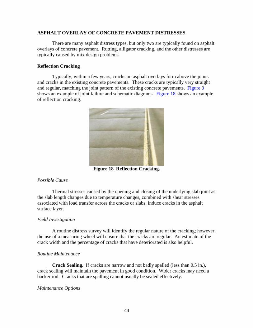
44
ASPHALT OVERLAY OF CONCRETE PAVEMENT DISTRESSES
There are many asphalt distress types, but only two are typically found on asphalt overlays of concrete pavement. Rutting, alligator cracking, and the other distresses are typically caused by mix design problems. Reflection Cracking
Typically, within a few years, cracks on asphalt overlays form above the joints and cracks in the existing concrete pavements. These cracks are typically very straight and regular, matching the joint pattern of the existing concrete pavements. Figure 3 shows an example of joint failure and schematic diagrams. Figure 18 shows an example of reflection cracking.
Figure 18 Reflection Cracking.
Possible Cause
Thermal stresses caused by the opening and closing of the underlying slab joint as the slab length changes due to temperature changes, combined with shear stresses associated with load transfer across the cracks or slabs, induce cracks in the asphalt surface layer.
Field Investigation
A routine distress survey will identify the regular nature of the cracking; however, the use of a measuring wheel will ensure that the cracks are regular. An estimate of the crack width and the percentage of cracks that have deteriorated is also helpful. Routine Maintenance
Crack Sealing. If cracks are narrow and not badly spalled (less than 0.5 in.), crack sealing will maintain the pavement in good condition. Wider cracks may need a backer rod. Cracks that are spalling cannot usually be sealed effectively. Maintenance Options
45
Patching with Asphalt Concrete. Patching with asphalt concrete can be used as a stopgap measure to temporarily improve ride quality. However, such patching may not last very long under traffic loading. Extensive patching may not be cost-effective.
Structural Rehabilitation Options
Crack Relief Layer and Structural Overlay. If the damaged area is extensive but not badly spalled, an overlay using the newer crack attenuating mixes can repair the damage and reduce the rate of deterioration.
Mill and Replace. If the damage is extensive and badly spalled, complete or partial removal and replacement are warranted. Prevention
The best preventive measure is to ensure that the underlying concrete has good load transfer prior to placing the overlay. Reflection Failure
A reflection failure is an area of pavement that is badly deteriorated due to the condition of the underlying pavement. The area is usually very broken, and pieces may be missing. Figure 19 shows an example of reflection failure.
Figure 19 Reflection Failure.
Possible Causes
The reflection failures are caused by a the reflection and surface deterioration due to the presence of a severely deteriorated patch, corner break, punchout, or shattered slab underneath the overlay. Field Investigation
To the extent possible, the underlying distress should be determined, and the field investigation should follow the procedure set for that distress.
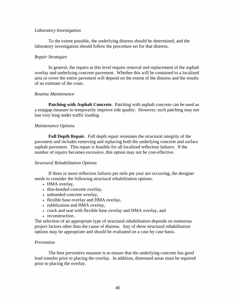
46
Laboratory Investigation
To the extent possible, the underlying distress should be determined, and the laboratory investigation should follow the procedure set for that distress. Repair Strategies
In general, the repairs at this level require removal and replacement of the asphalt overlay and underlying concrete pavement. Whether this will be contained to a localized area or cover the entire pavement will depend on the extent of the distress and the results of an estimate of the costs. Routine Maintenance
Patching with Asphalt Concrete. Patching with asphalt concrete can be used as a stopgap measure to temporarily improve ride quality. However, such patching may not last very long under traffic loading. Maintenance Options
Full Depth Repair. Full depth repair reinstates the structural integrity of the pavement and includes removing and replacing both the underlying concrete and surface asphalt pavement. This repair is feasible for all localized reflection failures. If the number of repairs becomes excessive, this option may not be cost-effective. Structural Rehabilitation Options
If three or more reflection failures per mile per year are occurring, the designer needs to consider the following structural rehabilitation options:
• HMA overlay, • thin-bonded concrete overlay, • unbonded concrete overlay, • flexible base overlay and HMA overlay, • rubblization and HMA overlay, • crack and seat with flexible base overlay and HMA overlay, and • reconstruction .
The selection of an appropriate type of structural rehabilitation depends on numerous project factors other than the cause of distress. Any of these structural rehabilitation options may be appropriate and should be evaluated on a case by case basis. Prevention
The best preventive measure is to ensure that the underlying concrete has good load transfer prior to placing the overlay. In addition, distressed areas must be repaired prior to placing the overlay.

47
CHAPTER 3 PAVEMENT CONDITION EVALUATION TECHNIQUES
FOR ROUTINE MAINTENANCE
Pavement condition evaluation is the key to determining proper routine maintenance activities. It is needed to validate the extent of distress-related damage, the quality of drainage, and relative base/subgrade layer strength. The pavement distress condition is considered relative to functional and structural performance in the decision process. The following evaluation techniques are recommended for strategic routine maintenance decisions (4):
• visual survey, • falling weight deflectometer, • ground penetrating radar, and • dynamic cone penetrometer.
VISUAL SURVEY
Selected project sites can be scanned to identify distressed areas to select locations for further inspection. There are many well-organized visual pavement condition survey protocols used by highway agencies to monitor and record pavement distresses. However, current survey protocols often require a level of inspection detail greater than what is normally needed for a routine maintenance survey; therefore, simplified survey tables are provided in Tables 3 and 4 to assist in the collection of routine maintenance information to meet critical decision criteria. The following information is collected on the simple survey form:
• general information about pavement — age and aggregate type; • condition record information — recent visual and deflection information; • condition of joint or crack sealing; • surface and subsurface drainage condition — possible locations for GPR and DCP
testing; • functional conditions — factors affecting riding quality and possible locations for
FWD, GPR, and DCP testing; • structural conditions — factors affecting premature failure of pavement and
possible locations for FWD, GPR, and DCP testing; and • identification of distressed areas for FDR.
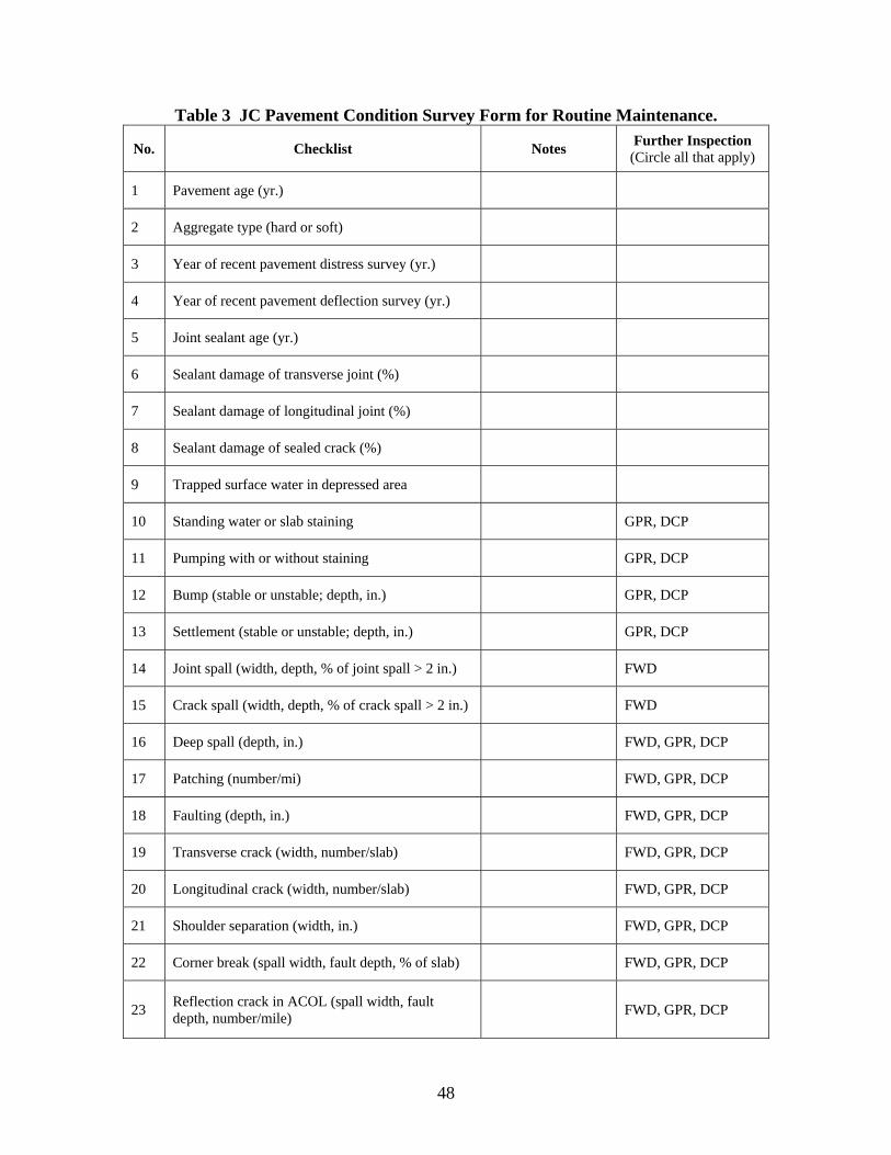
48
Table 3 JC Pavement Condition Survey Form for Routine Maintenance.
No. Checklist Notes Further Inspection (Circle all that apply)
1 Pavement age (yr.)
2 Aggregate type (hard or soft)
3 Year of recent pavement distress survey (yr.)
4 Year of recent pavement deflection survey (yr.)
5 Joint sealant age (yr.)
6 Sealant damage of transverse joint (%)
7 Sealant damage of longitudinal joint (%)
8 Sealant damage of sealed crack (%)
9 Trapped surface water in depressed area
10 Standing water or slab staining GPR, DCP
11 Pumping with or without staining GPR, DCP
12 Bump (stable or unstable; depth, in.) GPR, DCP
13 Settlement (stable or unstable; depth, in.) GPR, DCP
14 Joint spall (width, depth, % of joint spall > 2 in.) FWD
15 Crack spall (width, depth, % of crack spall > 2 in.) FWD
16 Deep spall (depth, in.) FWD, GPR, DCP
17 Patching (number/mi) FWD, GPR, DCP
18 Faulting (depth, in.) FWD, GPR, DCP
19 Transverse crack (width, number/slab) FWD, GPR, DCP
20 Longitudinal crack (width, number/slab) FWD, GPR, DCP
21 Shoulder separation (width, in.) FWD, GPR, DCP
22 Corner break (spall width, fault depth, % of slab) FWD, GPR, DCP
23 Reflection crack in ACOL (spall width, fault depth, number/mile) FWD, GPR, DCP
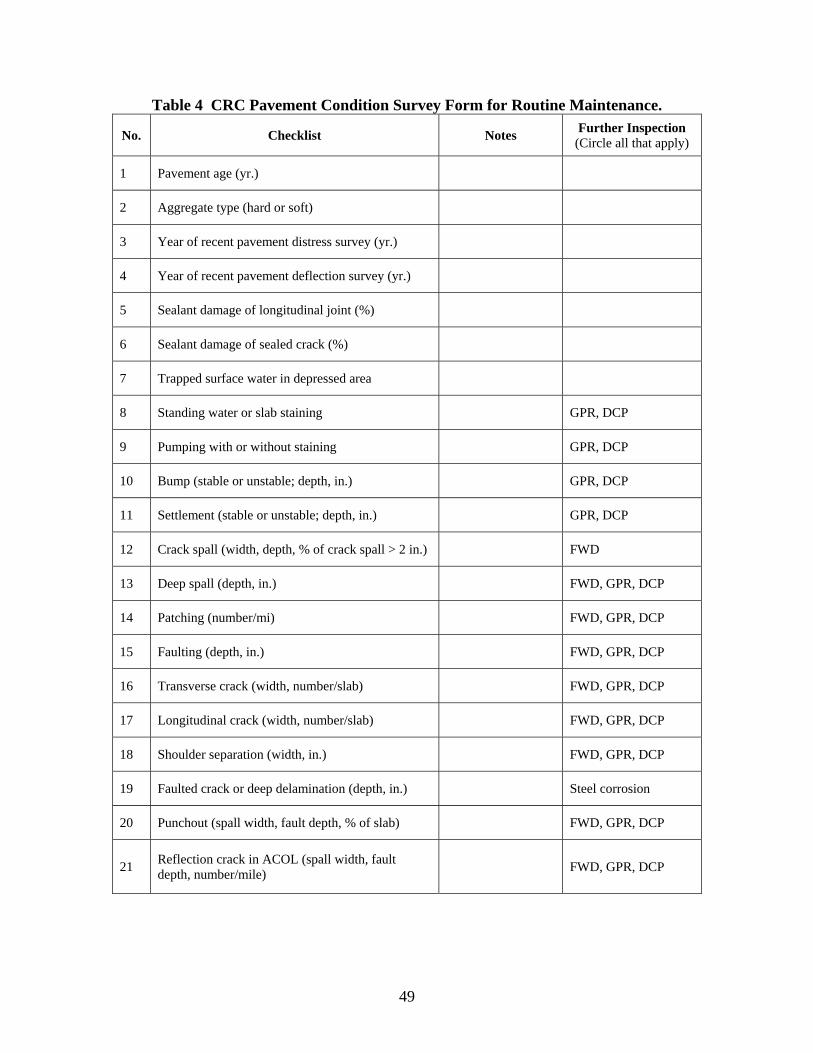
49
Table 4 CRC Pavement Condition Survey Form for Routine Maintenance.
No. Checklist Notes Further Inspection (Circle all that apply)
1 Pavement age (yr.)
2 Aggregate type (hard or soft)
3 Year of recent pavement distress survey (yr.)
4 Year of recent pavement deflection survey (yr.)
5 Sealant damage of longitudinal joint (%)
6 Sealant damage of sealed crack (%)
7 Trapped surface water in depressed area
8 Standing water or slab staining GPR, DCP
9 Pumping with or without staining GPR, DCP
10 Bump (stable or unstable; depth, in.) GPR, DCP
11 Settlement (stable or unstable; depth, in.) GPR, DCP
12 Crack spall (width, depth, % of crack spall > 2 in.) FWD
13 Deep spall (depth, in.) FWD, GPR, DCP
14 Patching (number/mi) FWD, GPR, DCP
15 Faulting (depth, in.) FWD, GPR, DCP
16 Transverse crack (width, number/slab) FWD, GPR, DCP
17 Longitudinal crack (width, number/slab) FWD, GPR, DCP
18 Shoulder separation (width, in.) FWD, GPR, DCP
19 Faulted crack or deep delamination (depth, in.) Steel corrosion
20 Punchout (spall width, fault depth, % of slab) FWD, GPR, DCP
21 Reflection crack in ACOL (spall width, fault depth, number/mile) FWD, GPR, DCP
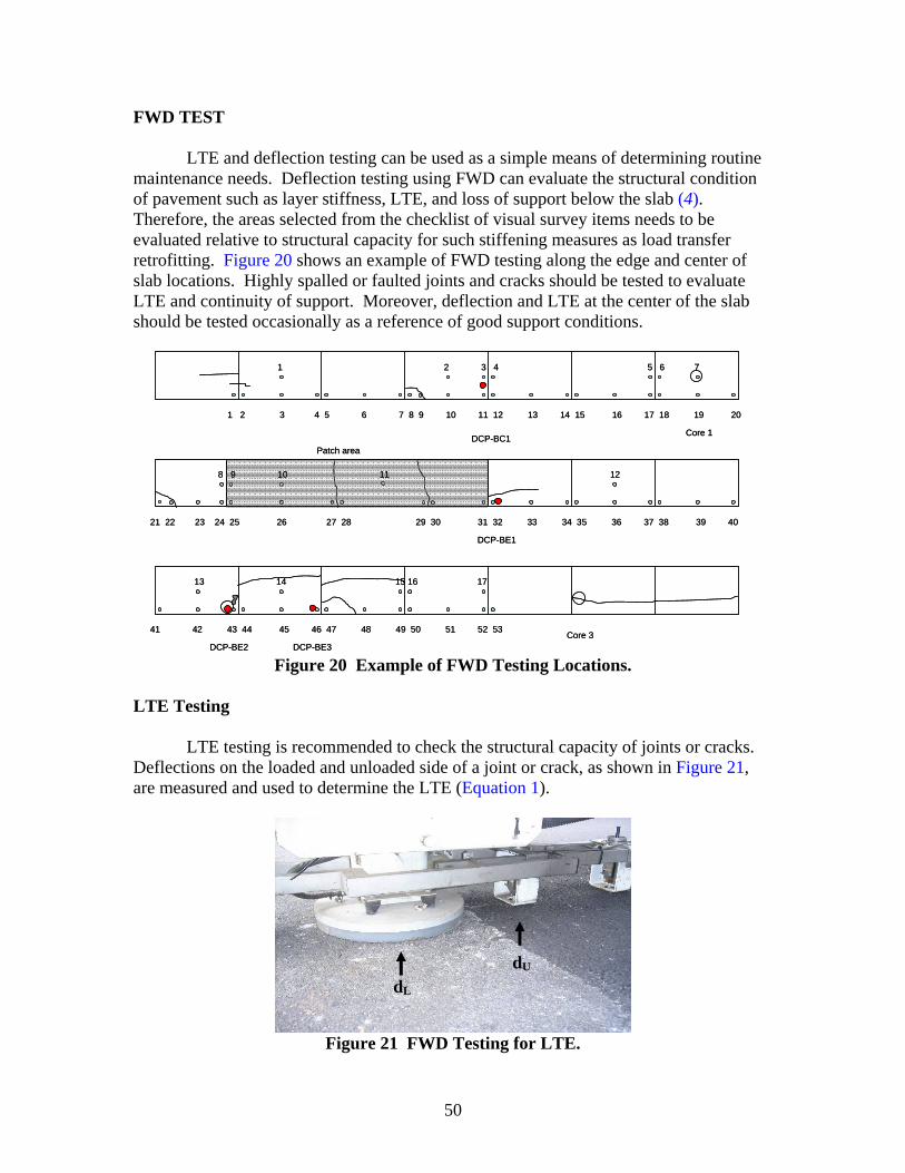
50
FWD TEST
LTE and deflection testing can be used as a simple means of determining routine maintenance needs. Deflection testing using FWD can evaluate the structural condition of pavement such as layer stiffness, LTE, and loss of support below the slab (4). Therefore, the areas selected from the checklist of visual survey items needs to be evaluated relative to structural capacity for such stiffening measures as load transfer retrofitting. Figure 20 shows an example of FWD testing along the edge and center of slab locations. Highly spalled or faulted joints and cracks should be tested to evaluate LTE and continuity of support. Moreover, deflection and LTE at the center of the slab should be tested occasionally as a reference of good support conditions.
1 2 3 4 5 6 7 8 9 10 11 12 13 14 15 16 17 18 19 20
21 22 23 24 25 26 27 28 29 30 31 32 33 34 35 36 37 38 39 40
41 42 43 44 45 46 47 48 49 50 51 52 53
1 2 3 4 5 6 7
8 9 10 11 12
13 14 15 16 17
DCP-BC1
DCP-BE1
DCP-BE2 DCP-BE3
Core 1
Core 3
Patch area
1 2 3 4 5 6 7 8 9 10 11 12 13 14 15 16 17 18 19 20
21 22 23 24 25 26 27 28 29 30 31 32 33 34 35 36 37 38 39 40
41 42 43 44 45 46 47 48 49 50 51 52 53
1 2 3 4 5 6 7
8 9 10 11 12
13 14 15 16 17
DCP-BC1
DCP-BE1
DCP-BE2 DCP-BE3
Core 1
Core 3
Patch area
Figure 20 Example of FWD Testing Locations.
LTE Testing
LTE testing is recommended to check the structural capacity of joints or cracks. Deflections on the loaded and unloaded side of a joint or crack, as shown in Figure 21, are measured and used to determine the LTE (Equation 1).
Figure 21 FWD Testing for LTE.
dL
dU
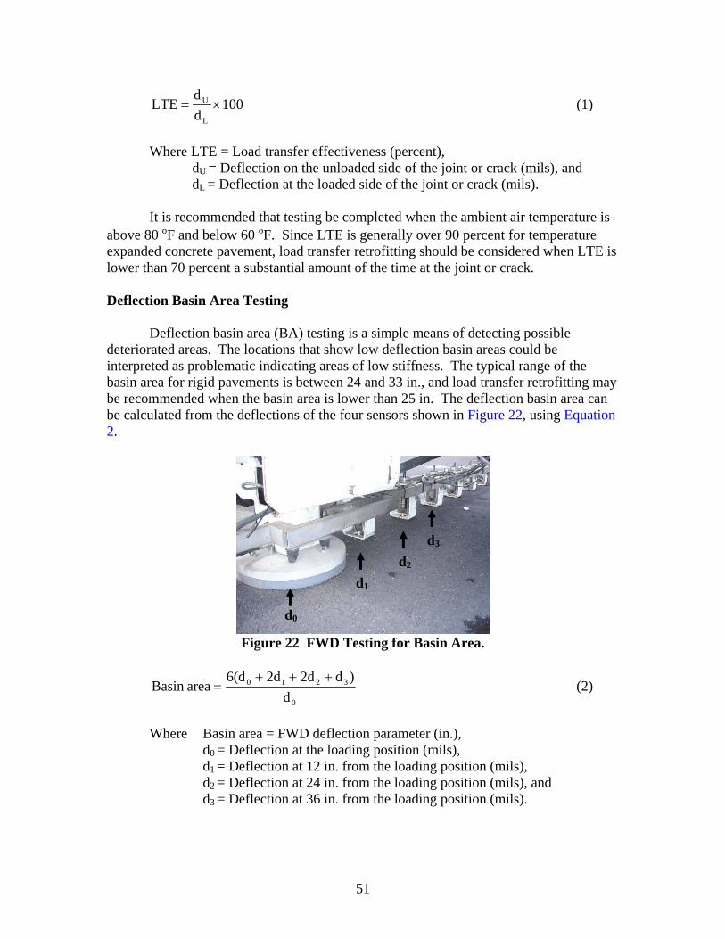
51
100dd
LTEL
U ×= (1)
Where LTE = Load transfer effectiveness (percent),
dU = Deflection on the unloaded side of the joint or crack (mils), and dL = Deflection at the loaded side of the joint or crack (mils).
It is recommended that testing be completed when the ambient air temperature is
above 80 oF and below 60 oF. Since LTE is generally over 90 percent for temperature expanded concrete pavement, load transfer retrofitting should be considered when LTE is lower than 70 percent a substantial amount of the time at the joint or crack. Deflection Basin Area Testing
Deflection basin area (BA) testing is a simple means of detecting possible deteriorated areas. The locations that show low deflection basin areas could be interpreted as problematic indicating areas of low stiffness. The typical range of the basin area for rigid pavements is between 24 and 33 in., and load transfer retrofitting may be recommended when the basin area is lower than 25 in. The deflection basin area can be calculated from the deflections of the four sensors shown in Figure 22, using Equation 2.
Figure 22 FWD Testing for Basin Area.
0
3210
d)dd2d26(d
areaBasin +++
= (2)
Where Basin area = FWD deflection parameter (in.), d0 = Deflection at the loading position (mils),
d1 = Deflection at 12 in. from the loading position (mils), d2 = Deflection at 24 in. from the loading position (mils), and
d3 = Deflection at 36 in. from the loading position (mils).
d0
d1
d2
d3
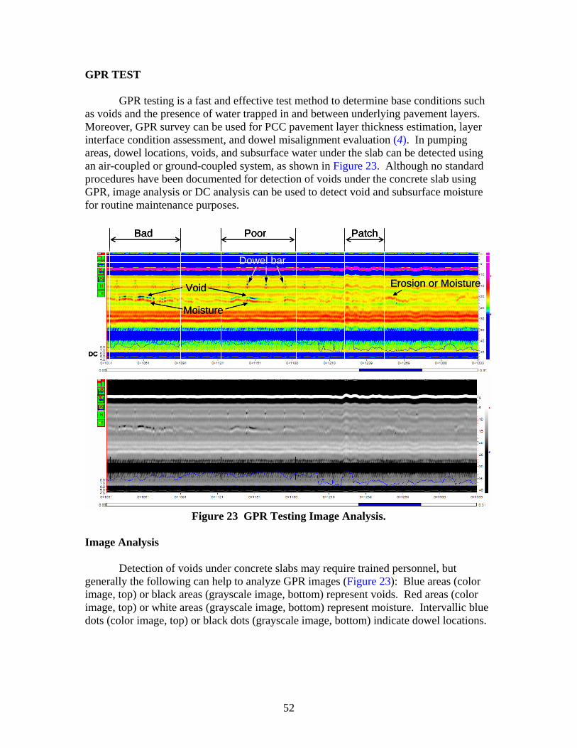
52
GPR TEST
GPR testing is a fast and effective test method to determine base conditions such as voids and the presence of water trapped in and between underlying pavement layers. Moreover, GPR survey can be used for PCC pavement layer thickness estimation, layer interface condition assessment, and dowel misalignment evaluation (4). In pumping areas, dowel locations, voids, and subsurface water under the slab can be detected using an air-coupled or ground-coupled system, as shown in Figure 23. Although no standard procedures have been documented for detection of voids under the concrete slab using GPR, image analysis or DC analysis can be used to detect void and subsurface moisture for routine maintenance purposes.
Bad Poor Patch
Void Erosion or Moisture
Moisture
DC
Bad Poor Patch
Void Erosion or Moisture
Moisture
DC
Bad Poor Patch
Void Erosion or Moisture
Moisture
DC
Figure 23 GPR Testing Image Analysis.
Image Analysis
Detection of voids under concrete slabs may require trained personnel, but generally the following can help to analyze GPR images (Figure 23): Blue areas (color image, top) or black areas (grayscale image, bottom) represent voids. Red areas (color image, top) or white areas (grayscale image, bottom) represent moisture. Intervallic blue dots (color image, top) or black dots (grayscale image, bottom) indicate dowel locations.
Dowel bar
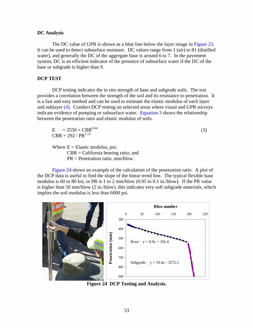
53
DC Analysis
The DC value of GPR is shown as a blue line below the layer image in Figure 23. It can be used to detect subsurface moisture. DC values range from 1 (air) to 81 (distilled water), and generally the DC of the aggregate base is around 6 to 7. In the pavement system, DC is an efficient indicator of the presence of subsurface water if the DC of the base or subgrade is higher than 9. DCP TEST
DCP testing indicates the in situ strength of base and subgrade soils. The test provides a correlation between the strength of the soil and its resistance to penetration. It is a fast and easy method and can be used to estimate the elastic modulus of each layer and sublayer (4). Conduct DCP testing on selected areas where visual and GPR surveys indicate evidence of pumping or subsurface water. Equation 3 shows the relationship between the penetration ratio and elastic modulus of soils.
E = 2550 × CBR0.64 (3) CBR = 292 / PR1.12 Where E = Elastic modulus, psi;
CBR = California bearing ratio; and PR = Penetration ratio, mm/blow.
Figure 24 shows an example of the calculation of the penetration ratio. A plot of the DCP data is useful to find the slope of the linear trend line. The typical flexible base modulus is 60 to 80 ksi, or PR is 1 to 2 mm/blow (0.05 to 0.1 in./blow). If the PR value is higher than 50 mm/blow (2 in./blow), this indicates very soft subgrade materials, which implies the soil modulus is less than 6000 psi.
y = 0.9x + 356.4
y = 19.4x - 3272.5
300
400
500
600
700
800
900
0 50 100 150 200 250
Blow number
Pene
trat
ion
(mm
)
Base:
Subgrade:
Figure 24 DCP Testing and Analysis.

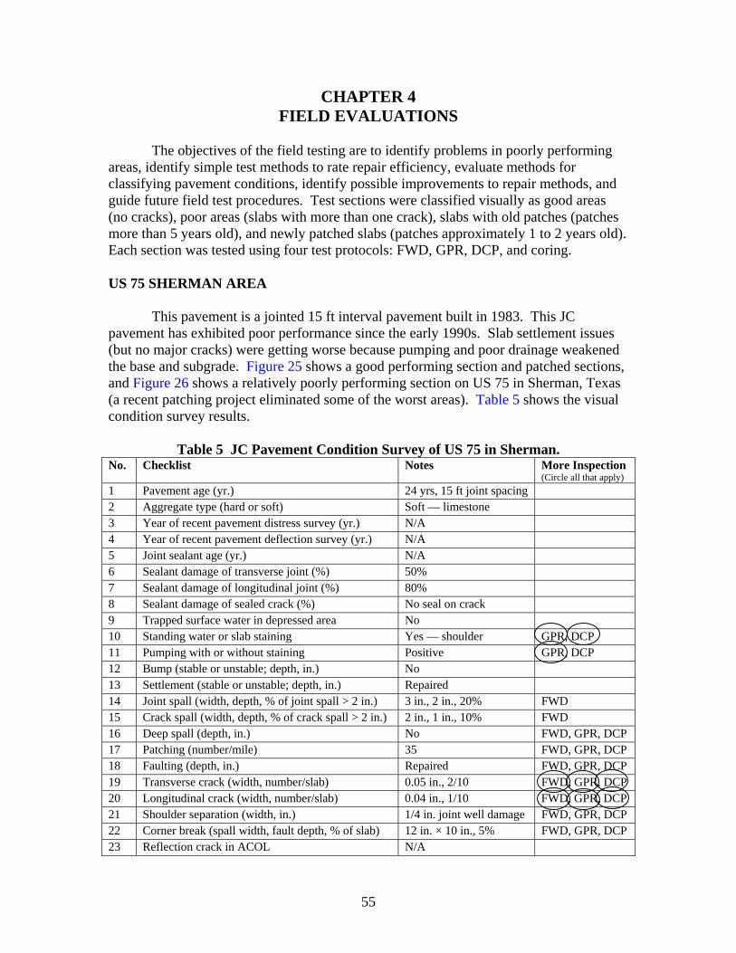
55
CHAPTER 4 FIELD EVALUATIONS
The objectives of the field testing are to identify problems in poorly performing
areas, identify simple test methods to rate repair efficiency, evaluate methods for classifying pavement conditions, identify possible improvements to repair methods, and guide future field test procedures. Test sections were classified visually as good areas (no cracks), poor areas (slabs with more than one crack), slabs with old patches (patches more than 5 years old), and newly patched slabs (patches approximately 1 to 2 years old). Each section was tested using four test protocols: FWD, GPR, DCP, and coring. US 75 SHERMAN AREA
This pavement is a jointed 15 ft interval pavement built in 1983. This JC pavement has exhibited poor performance since the early 1990s. Slab settlement issues (but no major cracks) were getting worse because pumping and poor drainage weakened the base and subgrade. Figure 25 shows a good performing section and patched sections, and Figure 26 shows a relatively poorly performing section on US 75 in Sherman, Texas (a recent patching project eliminated some of the worst areas). Table 5 shows the visual condition survey results.
Table 5 JC Pavement Condition Survey of US 75 in Sherman.
No. Checklist Notes More Inspection (Circle all that apply)
1 Pavement age (yr.) 24 yrs, 15 ft joint spacing 2 Aggregate type (hard or soft) Soft — limestone 3 Year of recent pavement distress survey (yr.) N/A 4 Year of recent pavement deflection survey (yr.) N/A 5 Joint sealant age (yr.) N/A 6 Sealant damage of transverse joint (%) 50% 7 Sealant damage of longitudinal joint (%) 80% 8 Sealant damage of sealed crack (%) No seal on crack 9 Trapped surface water in depressed area No 10 Standing water or slab staining Yes — shoulder GPR, DCP 11 Pumping with or without staining Positive GPR, DCP 12 Bump (stable or unstable; depth, in.) No 13 Settlement (stable or unstable; depth, in.) Repaired 14 Joint spall (width, depth, % of joint spall > 2 in.) 3 in., 2 in., 20% FWD 15 Crack spall (width, depth, % of crack spall > 2 in.) 2 in., 1 in., 10% FWD 16 Deep spall (depth, in.) No FWD, GPR, DCP 17 Patching (number/mile) 35 FWD, GPR, DCP 18 Faulting (depth, in.) Repaired FWD, GPR, DCP 19 Transverse crack (width, number/slab) 0.05 in., 2/10 FWD, GPR, DCP 20 Longitudinal crack (width, number/slab) 0.04 in., 1/10 FWD, GPR, DCP 21 Shoulder separation (width, in.) 1/4 in. joint well damage FWD, GPR, DCP 22 Corner break (spall width, fault depth, % of slab) 12 in. × 10 in., 5% FWD, GPR, DCP 23 Reflection crack in ACOL N/A
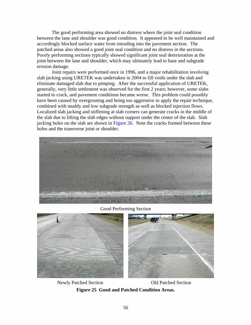
56
The good performing area showed no distress where the joint seal condition between the lane and shoulder was good condition. It appeared to be well maintained and accordingly blocked surface water from intruding into the pavement section. The patched areas also showed a good joint seal condition and no distress in the sections. Poorly performing sections typically showed significant joint seal deterioration at the joint between the lane and shoulder, which may ultimately lead to base and subgrade erosion damage.
Joint repairs were performed once in 1996, and a major rehabilitation involving slab jacking using URETEK was undertaken in 2004 to fill voids under the slab and eliminate damaged slab due to pimping. After the successful application of URETEK, generally, very little settlement was observed for the first 2 years; however, some slabs started to crack, and pavement conditions became worse. This problem could possibly have been caused by overgrouting and being too aggressive in apply the repair technique, combined with muddy and low subgrade strength as well as blocked injection flows. Localized slab jacking and stiffening at slab corners can generate cracks in the middle of the slab due to lifting the slab edges without support under the center of the slab. Slab jacking holes on the slab are shown in Figure 26. Note the cracks formed between these holes and the transverse joint or shoulder.
Good Performing Section
Newly Patched Section Old Patched Section
Figure 25 Good and Patched Condition Areas.
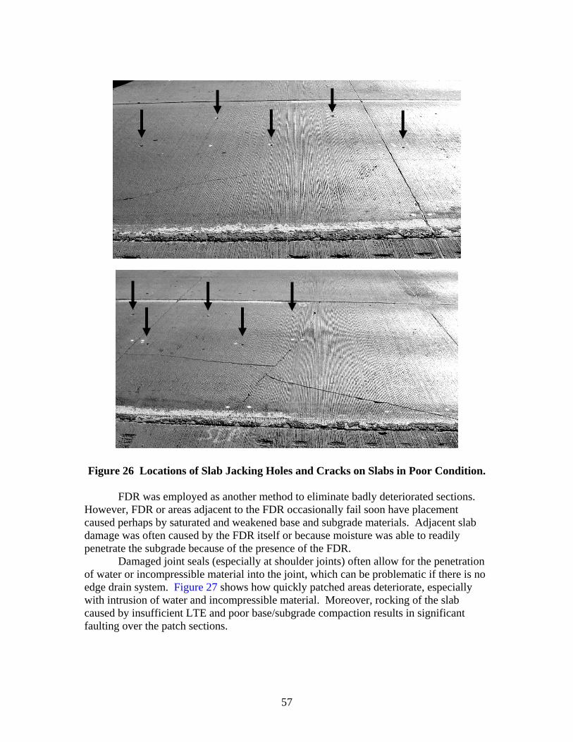
57
Figure 26 Locations of Slab Jacking Holes and Cracks on Slabs in Poor Condition.
FDR was employed as another method to eliminate badly deteriorated sections. However, FDR or areas adjacent to the FDR occasionally fail soon have placement caused perhaps by saturated and weakened base and subgrade materials. Adjacent slab damage was often caused by the FDR itself or because moisture was able to readily penetrate the subgrade because of the presence of the FDR.
Damaged joint seals (especially at shoulder joints) often allow for the penetration of water or incompressible material into the joint, which can be problematic if there is no edge drain system. Figure 27 shows how quickly patched areas deteriorate, especially with intrusion of water and incompressible material. Moreover, rocking of the slab caused by insufficient LTE and poor base/subgrade compaction results in significant faulting over the patch sections.
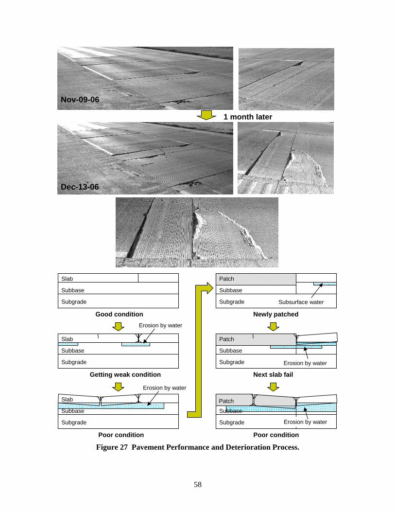
58
Figure 27 Pavement Performance and Deterioration Process.
Slab
Subbase
Subgrade
Slab
Subbase
Subgrade
Subbase
Subgrade
Subbase
Subgrade
Slab
Patch
Subgrade
Subbase
Subgrade
Subbase
Patch
Good condition
Getting weak condition
Poor condition
Newly patched
Patch
Next slab fail
Poor condition
Erosion by water
Erosion by water
Subsurface water
Erosion by water
Erosion by water
Nov-09-06
Dec-13-06
1 month later

59
Evaluation of Full Depth Repair Effectiveness
A combination of falling weight deflectometer testing and coring was used to evaluate the effectiveness of FDR sections and current JC pavement condition on US 75 in Sherman, Texas. The section profile was 10 in. thick over 6 in. of an unbound aggregate base and a natural weathered soil subgrade. Poorly performing sections were cracked, while other sections were free of cracks. Overall, the drainage condition appeared visually to be poor since there was significant standing water present in the borrow ditches alongside the sample sections. Falling Weight Deflectometer Testing
FWD testing is commonly using to check overall structural capacity such as slab stiffness, loss of support (voids), LTE of the joint, and basin area. Although backcalculation analysis involves theoretical related assumption, FWD test procedures are well established and simple to apply for investigation of pavement condition. Test locations consisted of testing before and after the joint and at the mid-slab location. These locations were tested along the edge of the slab, in the wheel paths, and at the center of the slab. Figure 28-a illustrates the FWD testing locations. LTE and basin area were backcalculated from FWD data to evaluate the relative pavement stiffness.
Figures 28-b and 28-c show joint LTE center and edge of slab. The LTEs before and after the joint are shown in the bar charts for each pavement condition. Unexpectedly, the poor condition section had the highest LTE along the slab edge, while the newly patched section had the lowest LTE (which was less than 40 percent). FDR efficiencies for the old patches are relatively low. Two out of five points associated with new patches had good LTE (approximately 80 percent and 90 percent), while the other three joints had poor LTE (approximately 50 percent, 10 percent, and 7 percent). The older patched sections providing good performance had better load transfer (approximately 70 to 80 percent). The reason for the failure of the FDR shown in Figure 27 is low LTE along with degraded base support.
Figure 28-d shows the mean and standard deviation of FWD basin areas. Patched sections show a lower mean basin area with a higher standard deviation than the cracked poorly performing area, which means the general structural capacity of FDR is lower than even the problematic pavement areas manifesting non-uniform support resulting in premature slab cracking. Existing patched areas can be checked using the FWD for structural adequacy; proper maintenance includes activities such as joint resealing and retrofit doweling to prolong the life of patched areas.
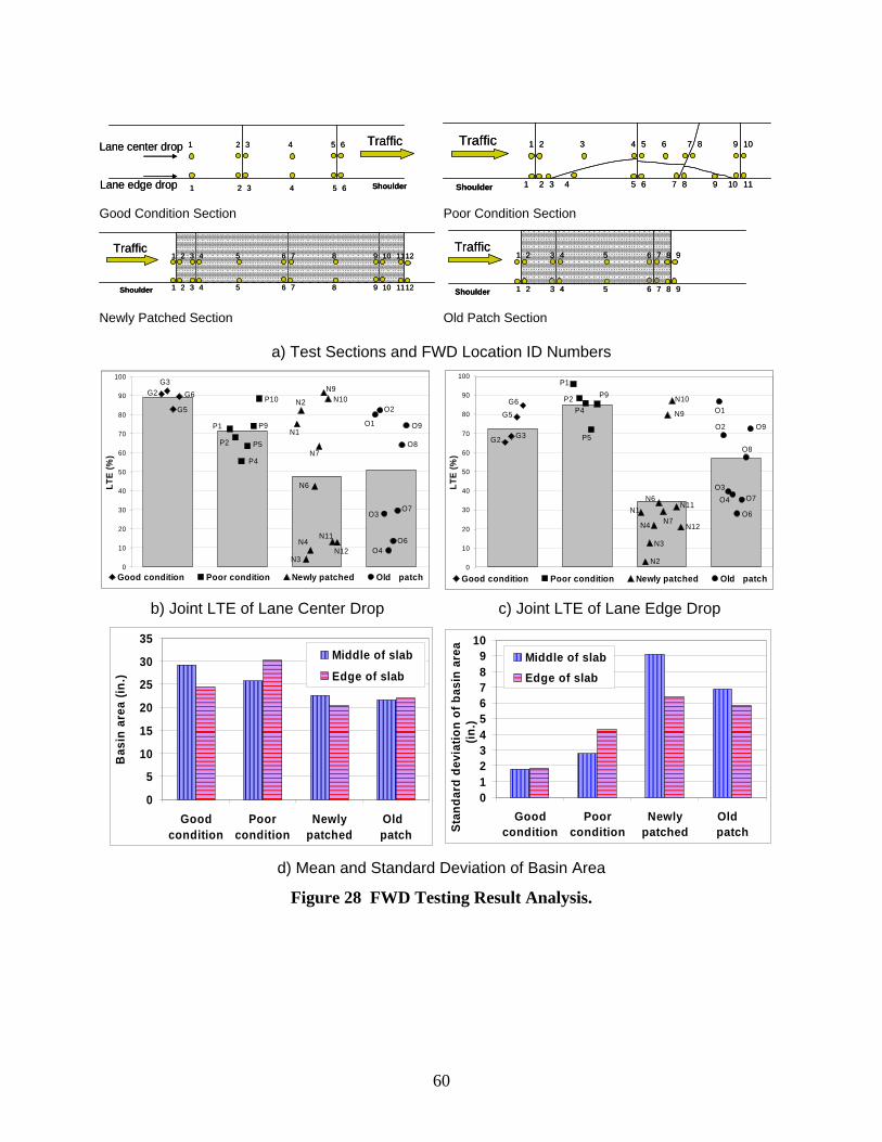
60
Traffic1 2 3 4 5 6
1 2 3 4 5 6 Shoulder
Lane center drop
Lane edge drop
Traffic1 2 3 4 5 6
1 2 3 4 5 6 Shoulder
Lane center drop
Lane edge drop
1 2 3 4 5 6 7 8 9 10
1 2 3 4 5 6 7 8 9 10 11Shoulder
Traffic 1 2 3 4 5 6 7 8 9 10
1 2 3 4 5 6 7 8 9 10 11Shoulder
Traffic
Good Condition Section Poor Condition Section
5 6 7 8 9 10 11121 2 3 4
5 6 7 8 9 10 11121 2 3 4Shoulder
Traffic5 6 7 8 9 10 11121 2 3 4
5 6 7 8 9 10 11121 2 3 4Shoulder
Traffic1 2 3 4 5 6 7 8 9
1 2 3 4 5 6 7 8 9Shoulder
Traffic1 2 3 4 5 6 7 8 9
1 2 3 4 5 6 7 8 9Shoulder
Traffic
Newly Patched Section Old Patch Section
a) Test Sections and FWD Location ID Numbers
0
10
20
30
40
50
60
70
80
90
100
LTE
(%)
Good condition Poor condition Newly patched Old patch
G2
G5
P1
P4
P9N1
N3
N6
N9
O1
O3
O6
O8
N11
G3G6
P2 P5
P10 N2
N4
N7
N10
N12
O2
O4
O7
O9
0
10
20
30
40
50
60
70
80
90
100
LTE
(%)
Good condition Poor condition Newly patched Old patch
G2
G6
P1
P4
P9
N1
N3
N6
N9 O1
O3
O6
O8
N7
G3
G5
P2
P5
N2
N4
N10
N11
O2
O4 O7
O9
N12
b) Joint LTE of Lane Center Drop c) Joint LTE of Lane Edge Drop
0
5
10
15
20
25
30
35
Goodcondition
Poorcondition
Newlypatched
Old patch
Bas
in a
rea
(in.)
Middle of slab
Edge of slab
0123456789
10
Goodcondition
Poorcondition
Newlypatched
Old patchSt
anda
rd d
evia
tion
of b
asin
are
a (in
.)
Middle of slabEdge of slab
d) Mean and Standard Deviation of Basin Area
Figure 28 FWD Testing Result Analysis.
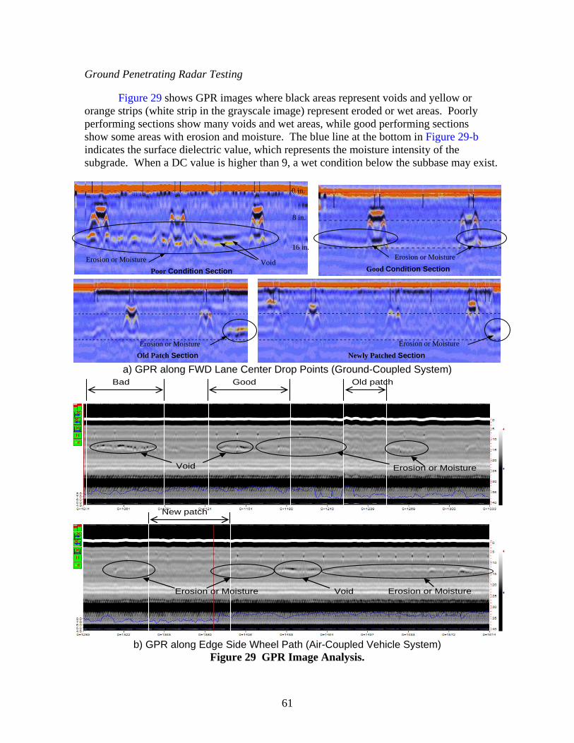
61
Ground Penetrating Radar Testing
Figure 29 shows GPR images where black areas represent voids and yellow or orange strips (white strip in the grayscale image) represent eroded or wet areas. Poorly performing sections show many voids and wet areas, while good performing sections show some areas with erosion and moisture. The blue line at the bottom in Figure 29-b indicates the surface dielectric value, which represents the moisture intensity of the subgrade. When a DC value is higher than 9, a wet condition below the subbase may exist.
a) GPR along FWD Lane Center Drop Points (Ground-Coupled System)
Void
New patch
Void Erosion or Moisture
Bad Good
Erosion or Moisture
Erosion or Moisture
Old patch
b) GPR along Edge Side Wheel Path (Air-Coupled Vehicle System) Figure 29 GPR Image Analysis.
Poor Condition Section Good Condition Section
Old Patch Section Newly Patched Section
Void
Erosion or Moisture
Erosion or Moisture
Erosion or Moisture
8 in.
16 in.
0 in.
Erosion or Moisture
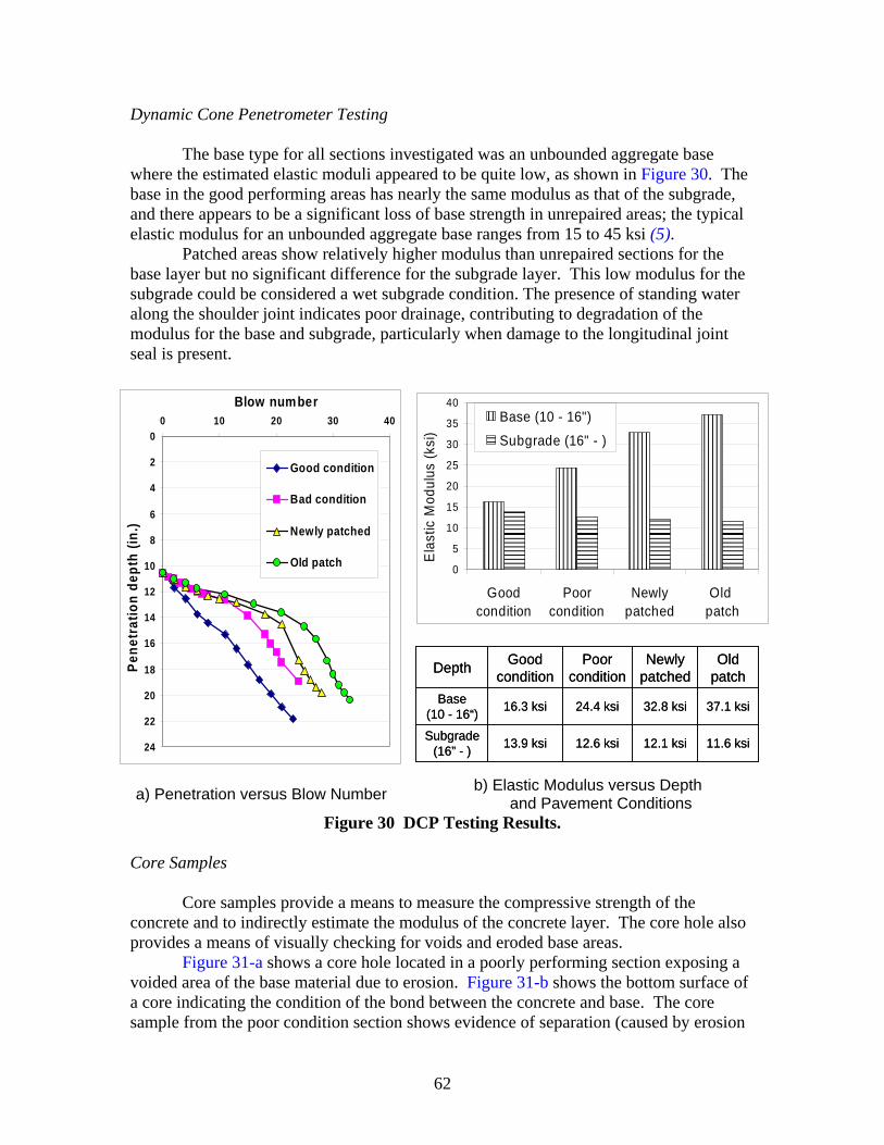
62
Dynamic Cone Penetrometer Testing
The base type for all sections investigated was an unbounded aggregate base where the estimated elastic moduli appeared to be quite low, as shown in Figure 30. The base in the good performing areas has nearly the same modulus as that of the subgrade, and there appears to be a significant loss of base strength in unrepaired areas; the typical elastic modulus for an unbounded aggregate base ranges from 15 to 45 ksi (5).
Patched areas show relatively higher modulus than unrepaired sections for the base layer but no significant difference for the subgrade layer. This low modulus for the subgrade could be considered a wet subgrade condition. The presence of standing water along the shoulder joint indicates poor drainage, contributing to degradation of the modulus for the base and subgrade, particularly when damage to the longitudinal joint seal is present.
0
5
10
15
20
25
30
35
40
Goodcondition
Poorcondition
Newlypatched
Old patch
Ela
stic
Mod
ulus
(ksi
)Base (10 - 16")
Subgrade (16" - )0
2
4
6
8
10
12
14
16
18
20
22
24
0 10 20 30 40Blow number
Pene
trat
ion
dept
h (in
.)
Good condition
Bad condition
Newly patched
Old patch
11.6 ksi12.1 ksi12.6 ksi13.9 ksiSubgrade(16” - )
37.1 ksi32.8 ksi24.4 ksi16.3 ksiBase (10 - 16“)
Old patch
Newly patched
Poor condition
Good conditionDepth
11.6 ksi12.1 ksi12.6 ksi13.9 ksiSubgrade(16” - )
37.1 ksi32.8 ksi24.4 ksi16.3 ksiBase (10 - 16“)
Old patch
Newly patched
Poor condition
Good conditionDepth
a) Penetration versus Blow Number b) Elastic Modulus versus Depth and Pavement Conditions
Figure 30 DCP Testing Results. Core Samples
Core samples provide a means to measure the compressive strength of the concrete and to indirectly estimate the modulus of the concrete layer. The core hole also provides a means of visually checking for voids and eroded base areas.
Figure 31-a shows a core hole located in a poorly performing section exposing a voided area of the base material due to erosion. Figure 31-b shows the bottom surface of a core indicating the condition of the bond between the concrete and base. The core sample from the poor condition section shows evidence of separation (caused by erosion
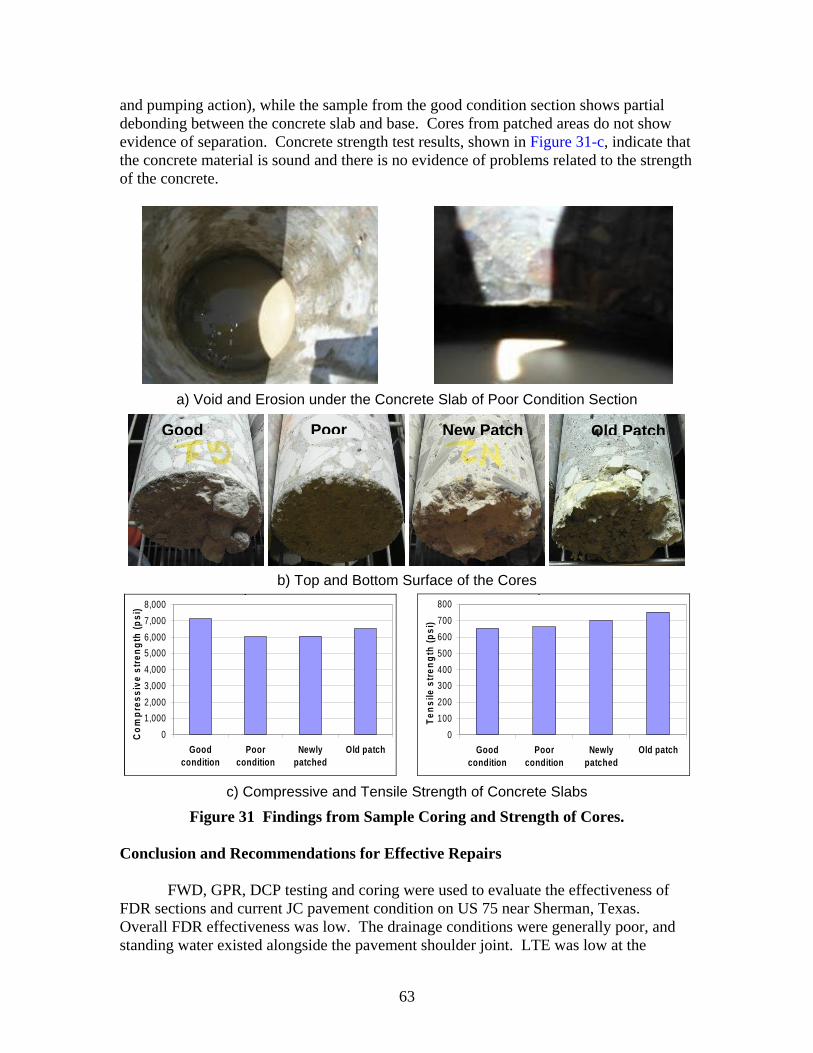
63
and pumping action), while the sample from the good condition section shows partial debonding between the concrete slab and base. Cores from patched areas do not show evidence of separation. Concrete strength test results, shown in Figure 31-c, indicate that the concrete material is sound and there is no evidence of problems related to the strength of the concrete.
a) Void and Erosion under the Concrete Slab of Poor Condition Section
b) Top and Bottom Surface of the Cores p
01,0002,0003,0004,0005,0006,0007,0008,000
Goodcondition
Poorcondition
Newlypatched
Old patch
Com
pres
sive
stre
ngth
(psi
)
p
0100200300400500600700800
Goodcondition
Poorcondition
Newlypatched
Old patch
Tens
ile s
treng
th (p
si)
c) Compressive and Tensile Strength of Concrete Slabs
Figure 31 Findings from Sample Coring and Strength of Cores. Conclusion and Recommendations for Effective Repairs
FWD, GPR, DCP testing and coring were used to evaluate the effectiveness of FDR sections and current JC pavement condition on US 75 near Sherman, Texas. Overall FDR effectiveness was low. The drainage conditions were generally poor, and standing water existed alongside the pavement shoulder joint. LTE was low at the
Good Poor New Patch Old Patch
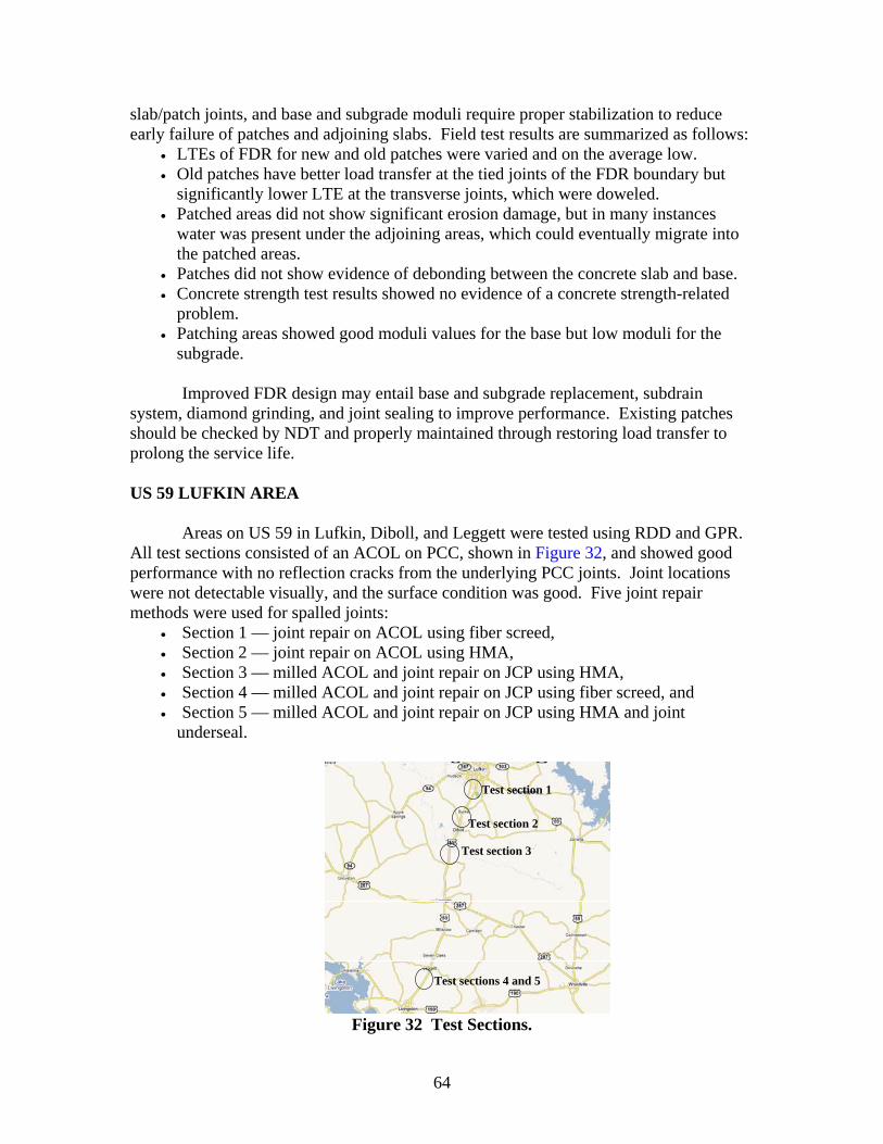
64
slab/patch joints, and base and subgrade moduli require proper stabilization to reduce early failure of patches and adjoining slabs. Field test results are summarized as follows:
• LTEs of FDR for new and old patches were varied and on the average low. • Old patches have better load transfer at the tied joints of the FDR boundary but
significantly lower LTE at the transverse joints, which were doweled. • Patched areas did not show significant erosion damage, but in many instances
water was present under the adjoining areas, which could eventually migrate into the patched areas.
• Patches did not show evidence of debonding between the concrete slab and base. • Concrete strength test results showed no evidence of a concrete strength-related
problem. • Patching areas showed good moduli values for the base but low moduli for the
subgrade.
Improved FDR design may entail base and subgrade replacement, subdrain system, diamond grinding, and joint sealing to improve performance. Existing patches should be checked by NDT and properly maintained through restoring load transfer to prolong the service life. US 59 LUFKIN AREA
Areas on US 59 in Lufkin, Diboll, and Leggett were tested using RDD and GPR. All test sections consisted of an ACOL on PCC, shown in Figure 32, and showed good performance with no reflection cracks from the underlying PCC joints. Joint locations were not detectable visually, and the surface condition was good. Five joint repair methods were used for spalled joints:
• Section 1 — joint repair on ACOL using fiber screed, • Section 2 — joint repair on ACOL using HMA, • Section 3 — milled ACOL and joint repair on JCP using HMA, • Section 4 — milled ACOL and joint repair on JCP using fiber screed, and • Section 5 — milled ACOL and joint repair on JCP using HMA and joint
underseal.
Test section 1
Test section 2
Test section 3
Test sections 4 and 5
Figure 32 Test Sections.
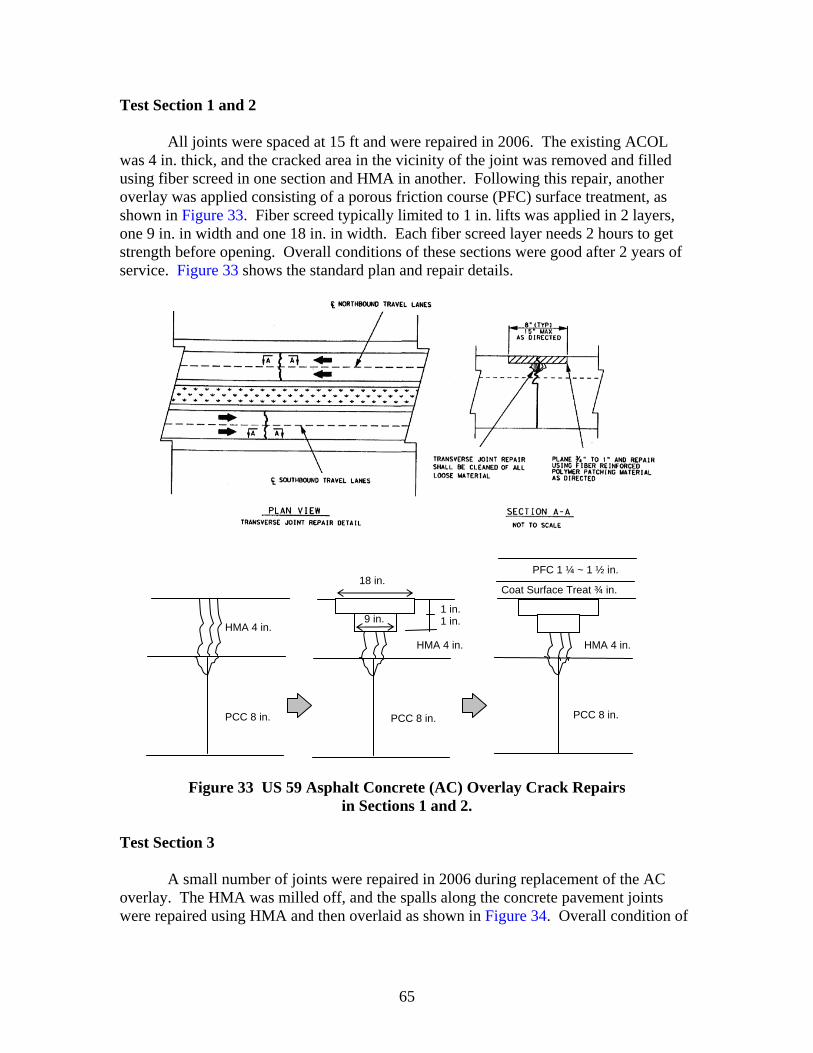
65
Test Section 1 and 2
All joints were spaced at 15 ft and were repaired in 2006. The existing ACOL was 4 in. thick, and the cracked area in the vicinity of the joint was removed and filled using fiber screed in one section and HMA in another. Following this repair, another overlay was applied consisting of a porous friction course (PFC) surface treatment, as shown in Figure 33. Fiber screed typically limited to 1 in. lifts was applied in 2 layers, one 9 in. in width and one 18 in. in width. Each fiber screed layer needs 2 hours to get strength before opening. Overall conditions of these sections were good after 2 years of service. Figure 33 shows the standard plan and repair details.
Figure 33 US 59 Asphalt Concrete (AC) Overlay Crack Repairs
in Sections 1 and 2.
Test Section 3
A small number of joints were repaired in 2006 during replacement of the AC overlay. The HMA was milled off, and the spalls along the concrete pavement joints were repaired using HMA and then overlaid as shown in Figure 34. Overall condition of
PFC 1 ¼ ~ 1 ½ in.
Coat Surface Treat ¾ in.
PCC 8 in.
HMA 4 in.
PCC 8 in.
HMA 4 in.
PCC 8 in.
HMA 4 in.
18 in.
9 in. 1 in. 1 in.
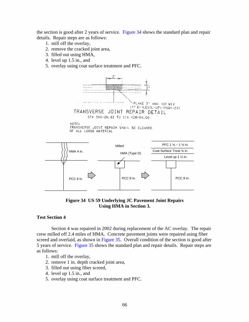
66
the section is good after 2 years of service. Figure 34 shows the standard plan and repair details. Repair steps are as follows:
1. mill off the overlay, 2. remove the cracked joint area, 3. filled out using HMA, 4. level up 1.5 in., and 5. overlay using coat surface treatment and PFC.
Figure 34 US 59 Underlying JC Pavement Joint Repairs
Using HMA in Section 3. Test Section 4
Section 4 was repaired in 2002 during replacement of the AC overlay. The repair
crew milled off 2.4 miles of HMA. Concrete pavement joints were repaired using fiber screed and overlaid, as shown in Figure 35. Overall condition of the section is good after 5 years of service. Figure 35 shows the standard plan and repair details. Repair steps are as follows:
1. mill off the overlay, 2. remove 1 in. depth cracked joint area, 3. filled out using fiber screed, 4. level up 1.5 in., and 5. overlay using coat surface treatment and PFC.
PFC 1 ¼ ~ 1 ½ in.
Coat Surface Treat ¾ in.
Level up 1 ½ in.
PCC 8 in.
HMA 4 in.
PCC 8 in. PCC 8 in.
Milled
HMA (Type D)
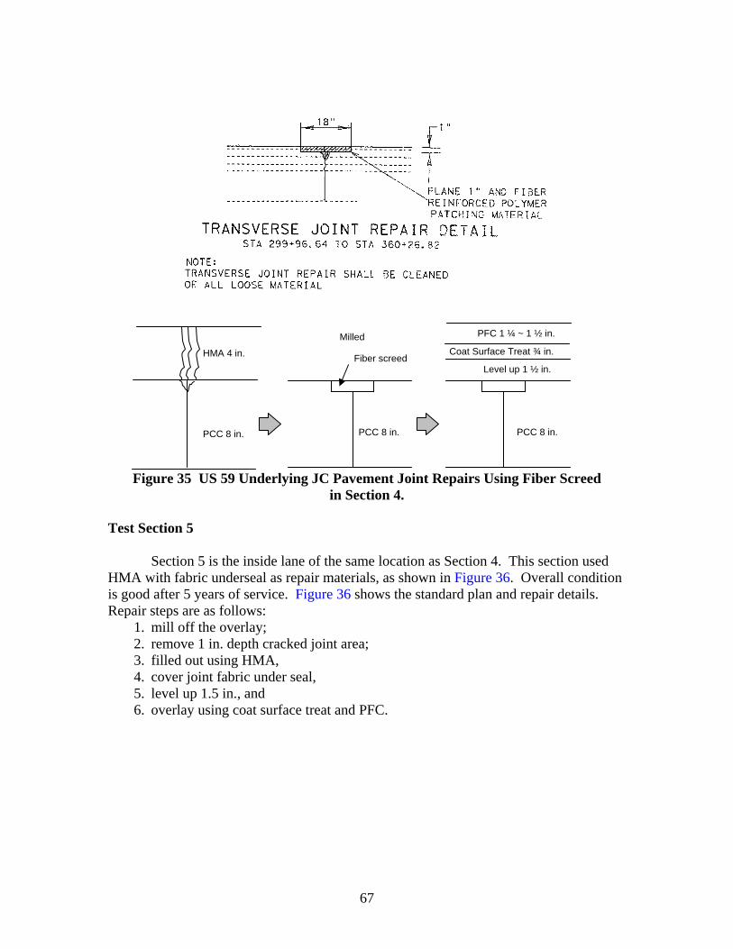
67
Figure 35 US 59 Underlying JC Pavement Joint Repairs Using Fiber Screed
in Section 4.
Test Section 5
Section 5 is the inside lane of the same location as Section 4. This section used HMA with fabric underseal as repair materials, as shown in Figure 36. Overall condition is good after 5 years of service. Figure 36 shows the standard plan and repair details. Repair steps are as follows:
1. mill off the overlay; 2. remove 1 in. depth cracked joint area; 3. filled out using HMA, 4. cover joint fabric under seal, 5. level up 1.5 in., and 6. overlay using coat surface treat and PFC.
PFC 1 ¼ ~ 1 ½ in.
Coat Surface Treat ¾ in.
Level up 1 ½ in.
PCC 8 in.
HMA 4 in.
PCC 8 in. PCC 8 in.
Milled
Fiber screed
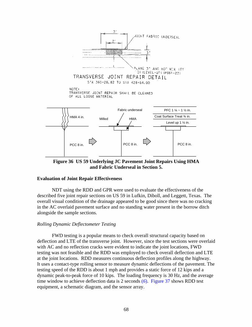
68
Figure 36 US 59 Underlying JC Pavement Joint Repairs Using HMA
and Fabric Underseal in Section 5.
Evaluation of Joint Repair Effectiveness
NDT using the RDD and GPR were used to evaluate the effectiveness of the described five joint repair sections on US 59 in Lufkin, Diboll, and Leggett, Texas. The overall visual condition of the drainage appeared to be good since there was no cracking in the AC overlaid pavement surface and no standing water present in the borrow ditch alongside the sample sections. Rolling Dynamic Deflectometer Testing
FWD testing is a popular means to check overall structural capacity based on deflection and LTE of the transverse joint. However, since the test sections were overlaid with AC and no reflection cracks were evident to indicate the joint locations, FWD testing was not feasible and the RDD was employed to check overall deflection and LTE at the joint locations. RDD measures continuous deflection profiles along the highway. It uses a contact-type rolling sensor to measure dynamic deflections of the pavement. The testing speed of the RDD is about 1 mph and provides a static force of 12 kips and a dynamic peak-to-peak force of 10 kips. The loading frequency is 30 Hz, and the average time window to achieve deflection data is 2 seconds (6). Figure 37 shows RDD test equipment, a schematic diagram, and the sensor array.
PFC 1 ¼ ~ 1 ½ in.
Coat Surface Treat ¾ in.
Level up 1 ½ in.
PCC 8 in.
HMA 4 in.
PCC 8 in. PCC 8 in.
Milled
Fabric underseal
HMA
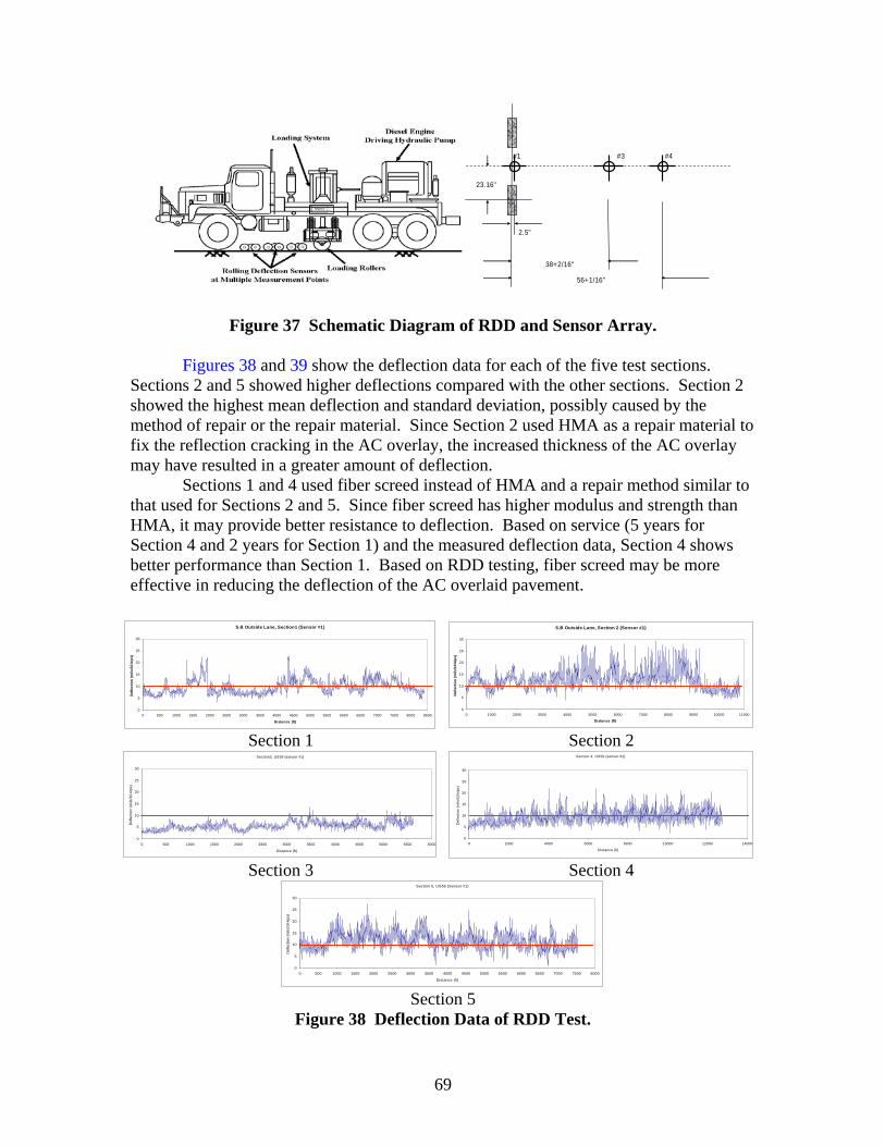
69
#1 #3 #4
2.5"
38+2/16"
56+1/16"
23.16"
Figure 37 Schematic Diagram of RDD and Sensor Array.
Figures 38 and 39 show the deflection data for each of the five test sections. Sections 2 and 5 showed higher deflections compared with the other sections. Section 2 showed the highest mean deflection and standard deviation, possibly caused by the method of repair or the repair material. Since Section 2 used HMA as a repair material to fix the reflection cracking in the AC overlay, the increased thickness of the AC overlay may have resulted in a greater amount of deflection.
Sections 1 and 4 used fiber screed instead of HMA and a repair method similar to that used for Sections 2 and 5. Since fiber screed has higher modulus and strength than HMA, it may provide better resistance to deflection. Based on service (5 years for Section 4 and 2 years for Section 1) and the measured deflection data, Section 4 shows better performance than Section 1. Based on RDD testing, fiber screed may be more effective in reducing the deflection of the AC overlaid pavement.
S.B Outside Lane, Section1 (Sensor #1)
0
5
10
15
20
25
30
0 500 1000 1500 2000 2500 3000 3500 4000 4500 5000 5500 6000 6500 7000 7500 8000 8500
Distance (ft)
Def
lect
ion
(mils
/10-
kips
)
S.B Outside Lane, Section 2 (Sensor #1)
0
5
10
15
20
25
30
0 1000 2000 3000 4000 5000 6000 7000 8000 9000 10000 11000
Distance (ft)
Defle
ctio
n (m
ils/1
0-ki
ps)
Section 1 Section 2 Section3, US59 (sensor #1)
0
5
10
15
20
25
30
0 500 1000 1500 2000 2500 3000 3500 4000 4500 5000 5500 6000
Distance (ft)
Def
lect
ion
(mils
/10-
kips
)
Section 4, US59 (sensor #1)
0
5
10
15
20
25
30
0 2000 4000 6000 8000 10000 12000 14000
Distance (ft)
Def
lect
ion
(mils
/10-
kips
)
Section 3 Section 4 Section 5, US59 (Sensor #1)
0
5
10
15
20
25
30
0 500 1000 1500 2000 2500 3000 3500 4000 4500 5000 5500 6000 6500 7000 7500 8000
Distance (ft)
Def
lect
ion
(mils
/10-
kips
)
Section 5
Figure 38 Deflection Data of RDD Test.
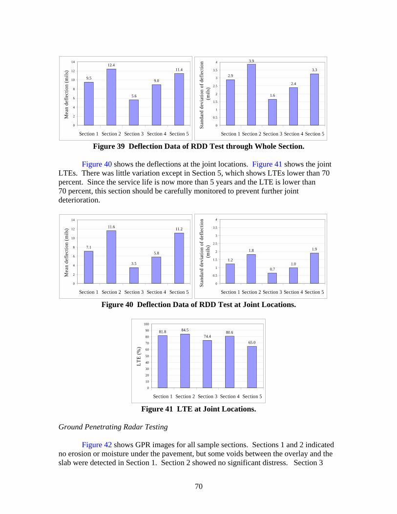
70
9.5
12.4
5.6
9.0
11.4
0
2
4
6
8
10
12
14
Section 1 Section 2 Section 3 Section 4 Section 5
Mea
n de
flect
ion
(mils
)
2.9
3.9
1.6
2.4
3.3
0
0.5
1
1.5
2
2.5
3
3.5
4
Section 1 Section 2 Section 3 Section 4 Section 5
Stan
dard
dev
iatio
n of
def
lect
ion
(mils
)
Figure 39 Deflection Data of RDD Test through Whole Section.
Figure 40 shows the deflections at the joint locations. Figure 41 shows the joint LTEs. There was little variation except in Section 5, which shows LTEs lower than 70 percent. Since the service life is now more than 5 years and the LTE is lower than 70 percent, this section should be carefully monitored to prevent further joint deterioration.
7.1
11.6
3.5
5.8
11.2
0
2
4
6
8
10
12
14
Section 1 Section 2 Section 3 Section 4 Section 5
Mea
n de
flect
ion
(mils
)
1.2
1.8
0.71.0
1.9
0
0.5
1
1.5
2
2.5
3
3.5
4
Section 1 Section 2 Section 3 Section 4 Section 5
Stan
dard
dev
iatio
n of
def
lect
ion
(mils
)
Figure 40 Deflection Data of RDD Test at Joint Locations.
81.8 84.574.4
80.6
65.0
0
10
20
30
40
50
60
70
80
90
100
Section 1 Section 2 Section 3 Section 4 Section 5
LTE
(%)
Figure 41 LTE at Joint Locations.
Ground Penetrating Radar Testing
Figure 42 shows GPR images for all sample sections. Sections 1 and 2 indicated no erosion or moisture under the pavement, but some voids between the overlay and the slab were detected in Section 1. Section 2 showed no significant distress. Section 3
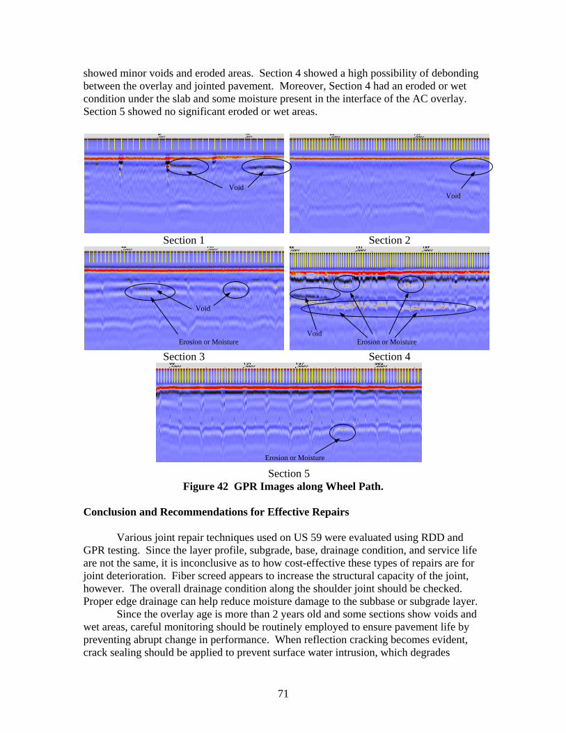
71
showed minor voids and eroded areas. Section 4 showed a high possibility of debonding between the overlay and jointed pavement. Moreover, Section 4 had an eroded or wet condition under the slab and some moisture present in the interface of the AC overlay. Section 5 showed no significant eroded or wet areas.
Section 1 Section 2
Section 3 Section 4
Section 5
Figure 42 GPR Images along Wheel Path. Conclusion and Recommendations for Effective Repairs
Various joint repair techniques used on US 59 were evaluated using RDD and GPR testing. Since the layer profile, subgrade, base, drainage condition, and service life are not the same, it is inconclusive as to how cost-effective these types of repairs are for joint deterioration. Fiber screed appears to increase the structural capacity of the joint, however. The overall drainage condition along the shoulder joint should be checked. Proper edge drainage can help reduce moisture damage to the subbase or subgrade layer.
Since the overlay age is more than 2 years old and some sections show voids and wet areas, careful monitoring should be routinely employed to ensure pavement life by preventing abrupt change in performance. When reflection cracking becomes evident, crack sealing should be applied to prevent surface water intrusion, which degrades
Erosion or Moisture
Void
Erosion or Moisture
Void
Void
Erosion or Moisture
Void

72
pavement over time. If joint faulting develops, milling the overlay and retrofitting load transfer are recommended to preserve pavement integrity. In the future, if pumping evidence is detected, particularly at the joint location, edge drainage should be considered to reduce moisture damage to the subbase or subgrade.
US 287 VERNON AND QUANAH AREAS Vernon Area Condition US 287 northbound JC pavement sections near Vernon, Texas, were tested using FWD, DCP, and coring. Figure 43 shows good and poor condition sections based on visual distress survey results. Both sections consist of 10 in., 15 ft jointed concrete pavement located 3 miles apart. The significant difference between them is that the good condition section has better joint sealing than the poor condition section. The crack and joint sealing in the poor condition section is damaged in many areas, and the shoulder joint is wide, as shown in Figure 43. Different aggregate type may be a factor in joint sealing problems. The aggregate type of the good condition area is limestone, and that of the poor condition area is gravel. Gravel has an approximately 50 percent higher coefficient of thermal expansion than limestone; therefore, joints and cracks in the poor condition section may have repeated wider opening and closing and more joint seal deterioration than the good condition section. Moreover, bounding gravel is negatively charged and more highly attracted to water.
Good Condition Section Poor Condition Section
Crack and Deteriorated Joint Sealing in Poor Condition Section
Figure 43 Test Sections in Vernon.
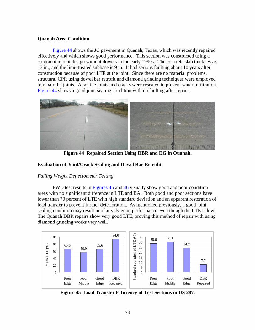
73
Quanah Area Condition Figure 44 shows the JC pavement in Quanah, Texas, which was recently repaired effectively and which shows good performance. This section was constructed using a contraction joint design without dowels in the early 1990s. The concrete slab thickness is 13 in., and the lime-treated subbase is 9 in. It had serious faulting about 10 years after construction because of poor LTE at the joint. Since there are no material problems, structural CPR using dowel bar retrofit and diamond grinding techniques were employed to repair the joints. Also, the joints and cracks were resealed to prevent water infiltration. Figure 44 shows a good joint sealing condition with no faulting after repair.
Figure 44 Repaired Section Using DBR and DG in Quanah.
Evaluation of Joint/Crack Sealing and Dowel Bar Retrofit Falling Weight Deflectometer Testing
FWD test results in Figures 45 and 46 visually show good and poor condition
areas with no significant difference in LTE and BA. Both good and poor sections have lower than 70 percent of LTE with high standard deviation and an apparent restoration of load transfer to prevent further deterioration. As mentioned previously, a good joint sealing condition may result in relatively good performance even though the LTE is low. The Quanah DBR repairs show very good LTE, proving this method of repair with using diamond grinding works very well.
65.656.9
65.6
94.0
0
20
40
60
80
100
PoorEdge
PoorMiddle
GoodEdge
DBRRepaired
Mea
n LT
E (%
)
28.6 30.124.2
7.7
05
101520253035
PoorEdge
PoorMiddle
GoodEdge
DBRRepaired
Stan
dard
dev
iatio
n of
LTE
(%)
Figure 45 Load Transfer Efficiency of Test Sections in US 287.
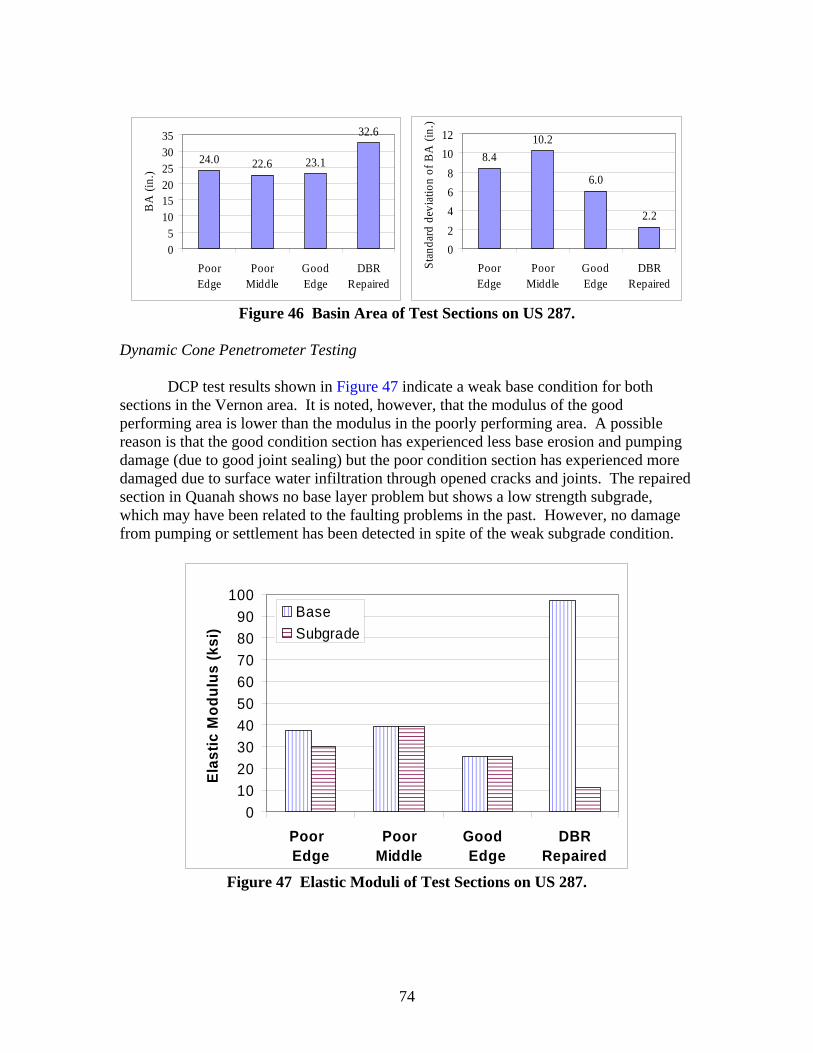
74
24.0 22.6 23.1
32.6
05
101520253035
PoorEdge
PoorMiddle
GoodEdge
DBRRepaired
BA
(in.
)
8.410.2
6.0
2.2
02468
1012
PoorEdge
PoorMiddle
GoodEdge
DBRRepaired
Stan
dard
dev
iatio
n of
BA
(in.
)
Figure 46 Basin Area of Test Sections on US 287.
Dynamic Cone Penetrometer Testing
DCP test results shown in Figure 47 indicate a weak base condition for both sections in the Vernon area. It is noted, however, that the modulus of the good performing area is lower than the modulus in the poorly performing area. A possible reason is that the good condition section has experienced less base erosion and pumping damage (due to good joint sealing) but the poor condition section has experienced more damaged due to surface water infiltration through opened cracks and joints. The repaired section in Quanah shows no base layer problem but shows a low strength subgrade, which may have been related to the faulting problems in the past. However, no damage from pumping or settlement has been detected in spite of the weak subgrade condition.
0102030405060708090
100
Poor Edge
PoorMiddle
Good Edge
DBRRepaired
Elas
tic M
odul
us (k
si)
BaseSubgrade
Figure 47 Elastic Moduli of Test Sections on US 287.
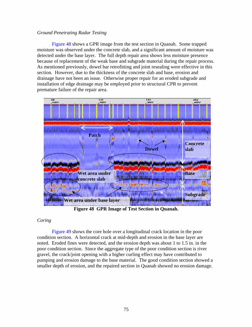
75
Ground Penetrating Radar Testing
Figure 48 shows a GPR image from the test section in Quanah. Some trapped moisture was observed under the concrete slab, and a significant amount of moisture was detected under the base layer. The full depth repair area shows less moisture presence because of replacement of the weak base and subgrade material during the repair process. As mentioned previously, dowel bar retrofitting and joint resealing were effective in this section. However, due to the thickness of the concrete slab and base, erosion and drainage have not been an issue. Otherwise proper repair for an eroded subgrade and installation of edge drainage may be employed prior to structural CPR to prevent premature failure of the repair area.
Figure 48 GPR Image of Test Section in Quanah.
Coring Figure 49 shows the core hole over a longitudinal crack location in the poor condition section. A horizontal crack at mid-depth and erosion in the base layer are noted. Eroded fines were detected, and the erosion depth was about 1 to 1.5 in. in the poor condition section. Since the aggregate type of the poor condition section is river gravel, the crack/joint opening with a higher curling effect may have contributed to pumping and erosion damage to the base material. The good condition section showed a smaller depth of erosion, and the repaired section in Quanah showed no erosion damage.
Wet area under base layer
Concrete slab
Base
Subgrade
Dowel
Patch
Wet area under concrete slab
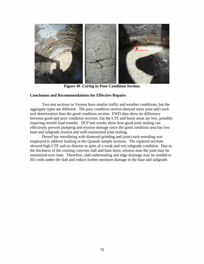
76
Figure 49 Coring in Poor Condition Section.
Conclusion and Recommendations for Effective Repairs
Two test sections in Vernon have similar traffic and weather conditions, but the aggregate types are different. The poor condition section showed more joint and crack seal deterioration than the good condition section. FWD data show no difference between good and poor condition sections, but the LTE and basin areas are low, possibly requiring retrofit load transfer. DCP test results show how good joint sealing can effectively prevent pumping and erosion damage since the good condition area has low base and subgrade erosion and well-maintained joint sealing.
Dowel bar retrofitting with diamond grinding and joint/crack resealing was employed to address faulting in the Quanah sample sections. The repaired sections showed high LTE and no distress in spite of a weak and wet subgrade condition. Due to the thickness of the existing concrete slab and base layer, erosion near the joint may be minimized over time. Therefore, slab undersealing and edge drainage may be needed to fill voids under the slab and reduce further moisture damage to the base and subgrade.
77
CHAPTER 5 REPAIR DECISION FLOWCHART FOR ROUTINE MAINTENANCE
Based on the pavement condition evaluation, a decision flowchart can provide
guidance for effective routine maintenance of AC overlaid or non-AC overlaid JC pavement and CRC pavement. The decision process for routine maintenance is categorized into five levels:
• performance monitoring, • preservative, • functional CPR, • structural CPR, and • remove and replace.
PERFORMANCE MONITORING Performance monitoring is basic and is the most important step to achieve effective routine maintenance for extending pavement service life. General pavement information needs to be assembled. Pavement age, aggregate type, traffic conditions, weather, and usual construction issues help decision makers understand the current pavement distress. If pavement age is more than 10 years for PCC or 2 years for AC overlaid pavement, the pavement condition survey should be updated.
Based on visual survey results, distressed areas may need further testing using pavement condition evaluation techniques such as FWD, GPR, and DCP to evaluate the structural condition. When pumping evidence is monitored, GPR surveying is especially useful to detect subsurface moisture and voided areas. FWD and DCP testing is useful to score the pavement’s structural condition for selecting proper maintenance repairs. PRESERVATIVE
Preservative maintenance is focused on providing minor treatment to minimize potential moisture damage, which is one of the most significant causes of deterioration of a concrete pavement system. The condition of the joint and crack seals and overall pavement drainage are key factors to prevent moisture damage due to water infiltration. Reseal Joints and Cracks
Crack and joint sealing condition is the first thing to check in a visual survey. Crack sealing is recommended when crack width is wider than 0.03 in. Resealing joints and cracks is recommended when sealants are damaged over more than 20 percent along the joint or crack to reduce infiltration of moisture and incompressible material over time.
This treatment is questionable for long-term effectiveness, but it can reduce pumping and faulting potential. Selection of proper sealing material should be based on temperature and moisture conditions; trapped subsurface water should be removed before re-sealing operations. Moreover, keep the joint well width smaller than 1 in. since widened joint wells may be noisy and degrade rideability.
78
If depressed areas are present, transverse grade re-profiling should be employed to provide drainage of the surface water because settled areas degrade riding quality and cause impact loading, and trapped surface water can cause safety problems and induce moisture damage through the joint or cracks.
Retrofit Edge Drains
If geometry and circumstances facilitate drainage, retrofitting the edge drain is recommended when water under the slab is identified or when the DC value is higher than 9 and the subgrade PR is smaller than 2 in. per blow.
However, edge drainage is not recommended if the base is unstabilized and the base contains more than 15 percent fines (passing No. 200 sieve) or if the pavement structure is undrainable. Proper design, construction, and maintenance are essential because edge drainage may accelerate deterioration of the base and subgrade if not maintained well. FUNCTIONAL CPR
Functional CPR can fix localized distress or overall riding quality problems, but it cannot increase the structural capacity of the pavement system significantly. Therefore, functional CPR can be used as a short-term solution or cooperative repair method with structural CPR to produce effective results. Partial Depth Repair
The objective of partial depth repair is to repair spall and distress without removing the entire slab. When 2 in. wide spalls are more than 10 percent of the crack or joint, partial depth repair should be employed using proper patching material for PCC pavement and AC overlaid PCC pavement. The depth of spall should be less than 1/3 the thickness of the slab, and the pavement should have no reinforcing steel exposure.
Partial depth repair also can be applied for deep delamination up to half of the CRC pavement thickness if the remaining slab is strong with no other distress and the steel is not corroded. Partial depth repairs should restore the joint face, and the joint should be sealed properly. Diamond Grinding
Rough and noisy patches, faulting, and bumps can be eliminated cost-effectively using diamond grinding. When patches are more than 10 per mile and faulting is more than 1/4 in., diamond grinding provides a smooth riding surface with good texture and reduces noise. When stabilized bumps or settled areas are present, diamond grinding can also be effective.
However, roughness will return if underlying causes are not addressed; therefore, restoration of load transfer before grinding is recommended. Grinding should not be employed for pavements with material problems or if the aggregate type is too hard to grind economically.
79
Thin ACOL
A thin AC overlay with petromat can be used to restore the functional capacity of
a pavement and improve rideability. Employing a thin AC overlay for hard aggregate pavements may be a good alternative to diamond grinding.
Existing structural distresses must be repaired and restored before the overlay is placed. This is important particularly if the pavement is structurally deficient to avoid premature failure. Use of a crack attenuating mix with good aggregate is recommended to minimize reflection cracking. STRUCTURAL CPR
The objective of structural CPR is to eliminate the cause of structural distresses and retrofit structural joint capacity to extend pavement service life. Structural CPR at the optimal time should increase pavement life. Generally, structural CPR needs functional CPR at the same time to achieve adequate results. Retrofit Road Transfer
Retrofit road transfer should be considered when faulting, high deflections, low LTE of the joint/crack, or reflection cracks in the ACOL are detected. When LTE is lower than 70 percent, the basin area is less than 25 in., and joints are spalled more than 2 in. wide over more than 20 percent, then restoration of road transfer is recommended to address faulting, pumping, and crack or joint deterioration.
Pavements exhibiting material-related distresses such as D-cracking or reactive aggregate are not candidates for retrofit road transfer. Before and after restoring road transfer, slab stabilization may be needed to address loss of support and diamond grinding needed to remove the existing faulting.
Cross Stitching
Cross stitching holds the longitudinal crack or joint together and prevents opening
and closing over time. Cross stitching should be considered when longitudinal cracks or shoulder joints separate wider than 1/2 in.
In the case of shoulder joint separation, cross stitching and joint sealing are
recommended when shoulder joint separation is between 1/2 in. and 1 in. in width. In order for joint sealing to be effective, the shoulder joint separation should remain smaller than 1/2 in.
Slab Undersealing
Slab undersealing is used to restore uniform support by filling voids and reducing
corner deflection, pumping, and faulting. Experienced contractors and proper inspection are essential to properly identify and underseal damaged areas. Therefore, GPR is
80
recommended to locate holes in a way that will ensure good grout distribution and void filling.
Slab undersealing is recommended when GPR-indicated voided cracks or joints are more than 20 percent of the inspected section or where unstable bumps or unstable settlement is present. REMOVE AND REPLACE This is the most expansive repair solution and extreme stage of repair of PCC pavement and is used when other maintenance techniques are not appropriate. Since full depth repair can be time consuming, precast concrete panels are recommended to reduce traffic congestion costs. Full Depth Repair
Full depth repair removes all deterioration in the distress area and restores load transfer at joints and cracks. This repair method should be considered when corner breaks are more than 10 percent or the slab is shattered in JC pavement and when punchouts are more than 10 percent in CRC pavement.
Soft subgrade materials may require removal and full depth repair, particularly in areas where cluster cracking is present. Grinding may be used to improve roughness created by placement of the FDR. If the deterioration is widespread over the entire project length, an overlay or reconstruction may be more cost-effective.
The decision flowcharts in Figures 50 and 51 are self-explanatory and provide guidance for effective routine maintenance.
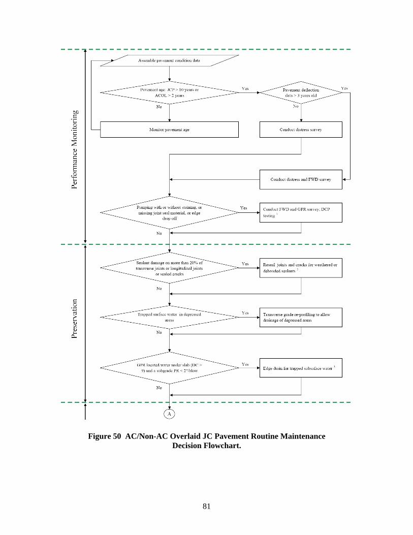
81
Figure 50 AC/Non-AC Overlaid JC Pavement Routine Maintenance
Decision Flowchart.

82
Figure 50. AC/Non-AC Overlaid JC Pavement Routine Maintenance
Decision Flowchart (Continued).
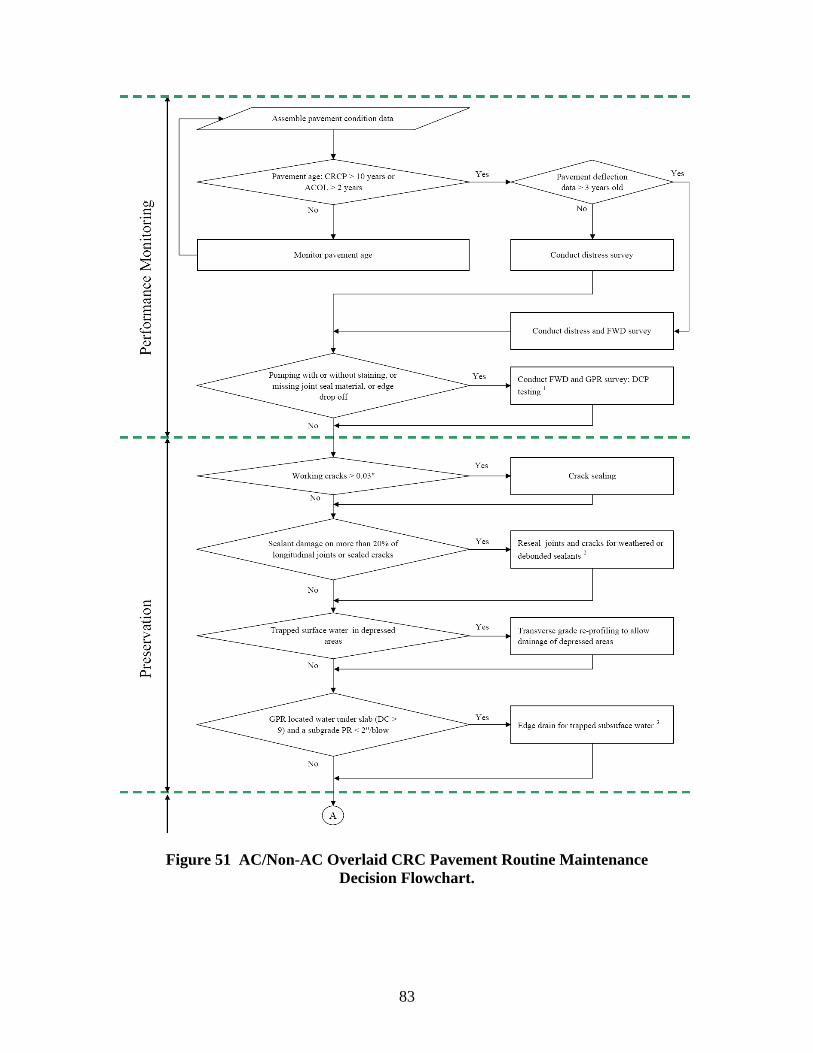
83
Figure 51 AC/Non-AC Overlaid CRC Pavement Routine Maintenance
Decision Flowchart.
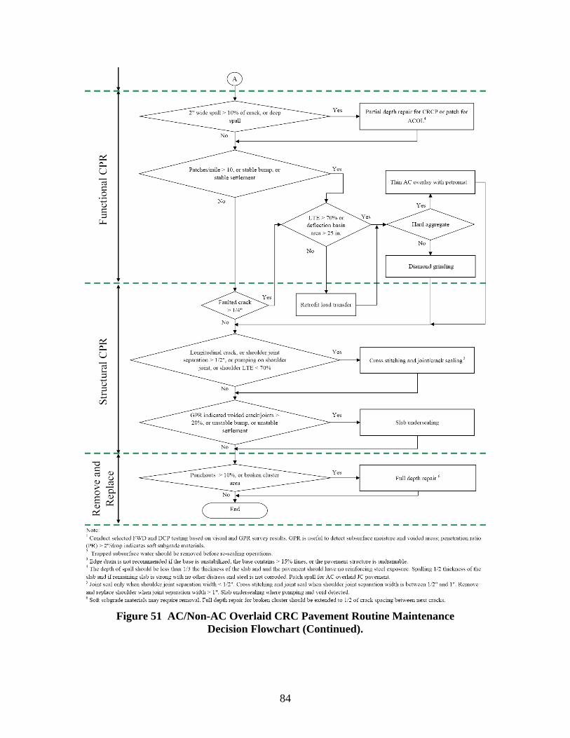
84
Figure 51 AC/Non-AC Overlaid CRC Pavement Routine Maintenance
Decision Flowchart (Continued).
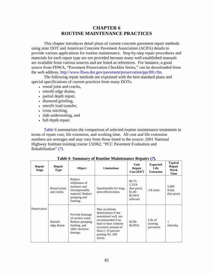
85
CHAPTER 6 ROUTINE MAINTENANCE PRACTICES
This chapter introduces detail plans of current concrete pavement repair methods
using state DOT and American Concrete Pavement Association (ACPA) details to provide various applications for routine maintenance. Step-by-step repair procedures and materials for each repair type are not provided because many well-established manuals are available from various sources and are listed as references. For instance, a good source from FHWA, “Pavement Preservation Checklist Series,” can be downloaded from the web address, http://www.fhwa.dot.gov/pavement/preservation/ppcl00.cfm. The following repair methods are explained with the best standard plans and special specifications of current practices from many DOTs:
• reseal joint and cracks, • retrofit edge drains, • partial depth repair, • diamond grinding, • retrofit load transfer, • cross stitching, • slab undersealing, and • full depth repair.
Table 6 summarizes the comparison of selected routine maintenance treatments in
terms of repair cost, life extension, and working time. All cost and life extension numbers are averages and may vary from those listed in the source: 2001 National Highway Institute training course 131062, “PCC Pavement Evaluation and Rehabilitation” (7).
Table 6 Summary of Routine Maintenance Repairs (7).
Repair Stage
Repair Type Object Limitations
Unit Repair
Cost ($/ft2)
Expected Life
Extension
Typical Repair Work Time
Reseal joints and cracks
Reduce infiltration of moisture and incompressible material. Reduce pumping and faulting.
Questionable for long-term effectiveness
$0.75-1.25/ft (hot pour), $1.00 - $2.00/ft (silicon)
3-8 years 5,000 ft/day (hot pour)
Preservative
Retrofit edge drains
Provide drainage of surface water. Reduce pumping, faulting, and other moisture damage.
May accelerate deterioration if not maintained well, not recommended if no base or base contains excessive amount of fines (>15 percent passing No. 200 sieve).
$2.00-$4.00/ft
Life of existing pavement
1 mile/day
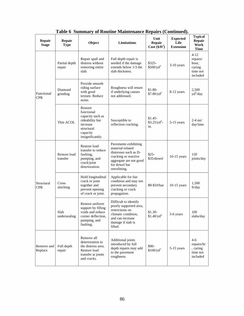
86
Table 6 Summary of Routine Maintenance Repairs (Continued).
Repair Stage
Repair Type Object Limitations
Unit Repair
Cost ($/ft2)
Expected Life
Extension
Typical Repair Work Time
Partial depth repair
Repair spall and distress without removing entire slab.
Full depth repair is needed if the damage extends below 1/3 the slab thickness.
$325-$500/yd3 3-10 years
4-12 repairs/ hour, curing time not included
Diamond grinding
Provide smooth riding surface with good texture. Reduce noise.
Roughness will return if underlying causes not addressed.
$1.80-$7.80/yd2 8-12 years 2,500
yd2/day Functional CPR
Thin ACOL
Restore functional capacity such as rideability but increase structural capacity insignificantly.
Susceptible to reflection cracking.
$1.45-$3.25/yd2-in.
5-15 years 2-4 mi/ day/lane
Restore load transfer
Restore load transfer to reduce faulting, pumping, and crack/joint deterioration.
Pavements exhibiting material-related distresses such as D-cracking or reactive aggregate are not good for dowel bar retrofitting.
$25-$35/dowel 10-15 years 150
joints/day
Cross stitching
Hold longitudinal crack or joint together and prevent opening of crack or joint.
Applicable for fair condition and may not prevent secondary cracking or crack propagation.
$9-$10/bar 10-15 years 1,500 ft/day
Structural CPR
Slab undersealing
Restore uniform support by filling voids and reduce corner deflection, pumping, and faulting.
Difficult to identify poorly supported area, restrictions on climatic condition, and can increase damage if slab is lifted.
$1.30-$1.40/yd2 3-6 years 100
slabs/day
Remove and Replace
Full depth repair
Remove all deterioration in the distress area. Restore load transfer at joints and cracks.
Additional joints introduced by full depth repairs may add to the pavement roughness.
$90-$100/yd2 5-15 years
4-6 repairs/hr, curing time not included
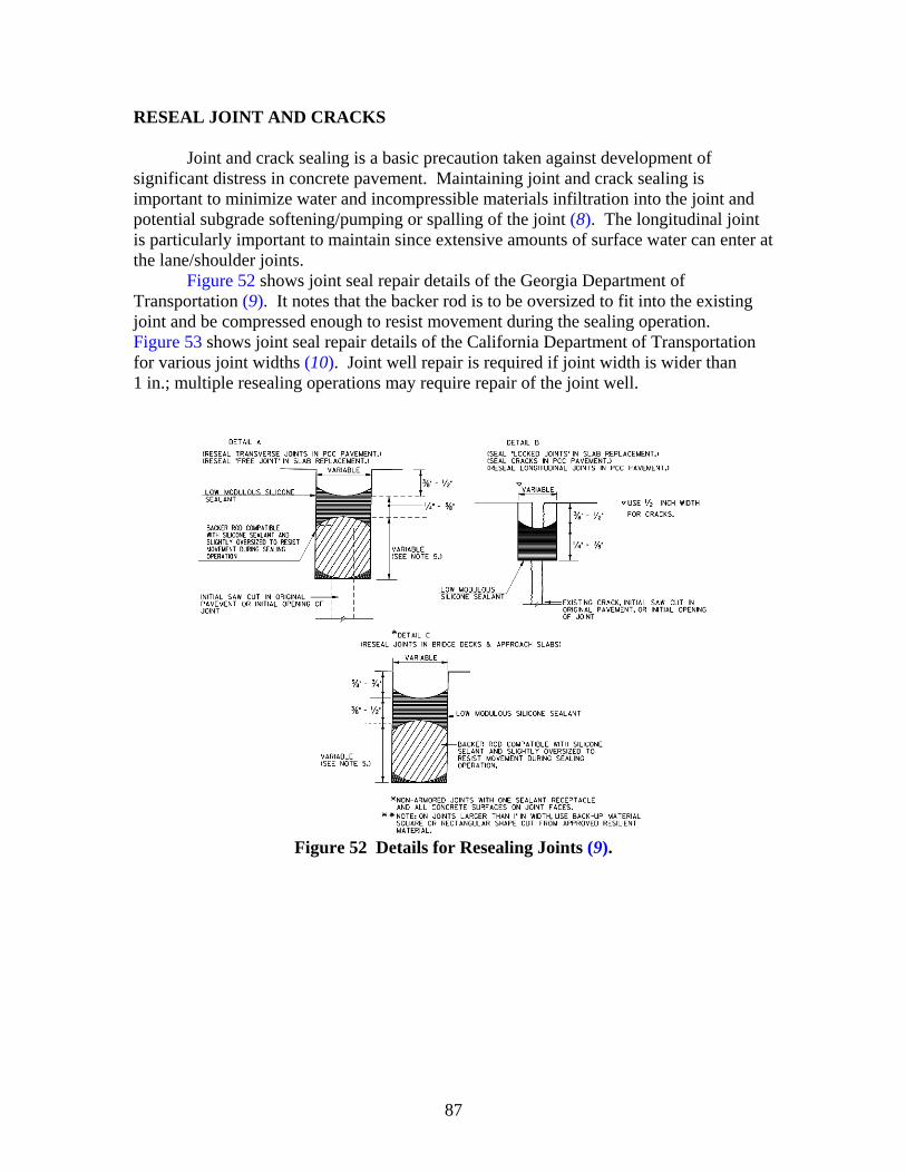
87
RESEAL JOINT AND CRACKS
Joint and crack sealing is a basic precaution taken against development of significant distress in concrete pavement. Maintaining joint and crack sealing is important to minimize water and incompressible materials infiltration into the joint and potential subgrade softening/pumping or spalling of the joint (8). The longitudinal joint is particularly important to maintain since extensive amounts of surface water can enter at the lane/shoulder joints.
Figure 52 shows joint seal repair details of the Georgia Department of Transportation (9). It notes that the backer rod is to be oversized to fit into the existing joint and be compressed enough to resist movement during the sealing operation. Figure 53 shows joint seal repair details of the California Department of Transportation for various joint widths (10). Joint well repair is required if joint width is wider than 1 in.; multiple resealing operations may require repair of the joint well.
Figure 52 Details for Resealing Joints (9).
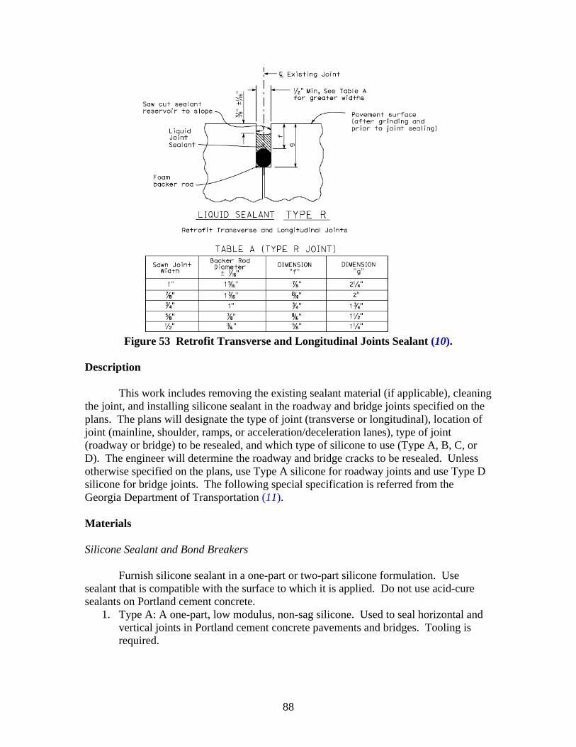
88
Figure 53 Retrofit Transverse and Longitudinal Joints Sealant (10).
Description
This work includes removing the existing sealant material (if applicable), cleaning the joint, and installing silicone sealant in the roadway and bridge joints specified on the plans. The plans will designate the type of joint (transverse or longitudinal), location of joint (mainline, shoulder, ramps, or acceleration/deceleration lanes), type of joint (roadway or bridge) to be resealed, and which type of silicone to use (Type A, B, C, or D). The engineer will determine the roadway and bridge cracks to be resealed. Unless otherwise specified on the plans, use Type A silicone for roadway joints and use Type D silicone for bridge joints. The following special specification is referred from the Georgia Department of Transportation (11). Materials Silicone Sealant and Bond Breakers
Furnish silicone sealant in a one-part or two-part silicone formulation. Use sealant that is compatible with the surface to which it is applied. Do not use acid-cure sealants on Portland cement concrete.
1. Type A: A one-part, low modulus, non-sag silicone. Used to seal horizontal and vertical joints in Portland cement concrete pavements and bridges. Tooling is required.
89
2. Type B: A one-part, very low modulus, self-leveling silicone. Used to seal horizontal joints in Portland cement concrete pavements and bridges. Tooling is not normally required.
3. Type C: A one-part, ultra-low modulus, self-leveling silicone. Used to seal horizontal joints in Portland cement concrete pavements and bridges and joints between Portland cement concrete pavement and asphaltic concrete shoulders. Tooling is not normally required.
4. Type D: A two-part, ultra-low modulus, self-leveling, rapid cure silicone. Used to seal horizontal joints in Portland cement concrete pavements and bridges and joints between Portland cement concrete pavement and asphaltic concrete shoulders. Tooling is not required.
Bond Breakers Bond breakers shall be chemically inert and resistant to oils, gasoline, solvents, and primer if one is required. Install silicone sealants over a bond breaker to prevent the sealant from bonding to the bottom of the joint. Epoxy Resin Adhesives
Furnish the epoxy adhesive as two separate components. Equipment Air Compressors Use air compressors equipped with traps to remove surplus water and oil in the compressed air. Do not use contaminated air. Ensure that the compressor can deliver compressed air at a continuous pressure of at least 90 psi (600 kPa). The engineer may check the compressed air for contamination. Silicone Sealant Pump Apply silicone sealant by pumping only. Use a caulking gun with a cartridge for touch-up work or small applications only. Use a pump with sufficient capacity to deliver the necessary volume of silicone to completely fill the joint in a single pass. Ensure that the nozzle’s size and shape closely fit into the joint to fill the joint with sealant using enough force to prevent voids in the sealant and to force the sealant to contact the joint faces. Caulking Gun Use a caulking gun with cartridge for the following situations: (a) touch-up work; (b) placing vertical runs of Type A silicone in a bridge deck joint when Type B, C, or D silicone is used in the horizontal runs; (c) sealing voids and cracks with Type A silicone
90
where Type B, C, or D silicone (which will be applied on top of the Type A silicone) might leak through; and (d) sealing small cracks in the concrete. Construction Method Preparation
Before installing a bond breaker or sealant, ensure that the joint is clean and dry. Complete all cleaning, air blasting, or air drying.
Resealing Existing Joints
1. Remove Existing Sealant. Completely remove the existing sealant in the joints. Take care during removal and cleaning to prevent damaging or enlarging the existing width of the joint. Repair any damaged areas at no cost to the department.
2. Depth of Existing Joint. Determine if the joint depth will accommodate the required sealant thickness and bond breaker and provide the required recess below the riding surface. Consider that the backer rod is thicker after it is squeezed into the joint. If necessary, saw the existing joint deeper and wider to provide the joint depth and width specified on the plans.
3. Clean the Joint. Thoroughly clean the joint of all foreign material including oil, asphalt, curing compound, sealant adhesive, paint, rust, and existing sealant if still present. Demonstrate to the engineer that the proposed method of cleaning old sealant or foreign material from joints will not widen the joints by more than 0.040 in. (1 mm). The method shall not alter the joint profile (including rounding of the top corner) or alter the texture of the concrete riding surface. Do not use chemical agents to clean the joint. Ensure that the cleaning process produces a new, clean concrete face on the vertical faces of the joint.
Sealing New Joints
1. Sawing. Saw the transverse and longitudinal joints according to the
specifications and plan details. a. Make the initial cut and wait for the concrete to harden enough to prevent
spalling or raveling. b. Make the second cut to the width and depth shown on the plans. c. Do not use a gang saw to make a completed cut in a single operation. d. If spalling of the sawed edge harms the joint seal, patch the spall with an
approved epoxy patching compound and allow it to fully cure before installing the joint sealant.
e. Make each patch to the intended neat lines of the finished cut joint. 2. Cleaning Freshly Cut Sawed Joints. Immediately after sawing the joint do the
following:
91
a. Completely remove the resulting slurry from the joint and clean the immediate area by flushing it with a jet of water under pressure. Use other tools as necessary.
b. When the surfaces are thoroughly clean and dry and immediately before placing the joint sealer, use compressed air with a pressure of at least 90 psi (620 kPa) to blow out the joint and remove dust traces.
c. If freshly cut sawed joints are contaminated before they are sealed, clean them before seal.
d. Ensure that cleaning methods do not alter the joint profile, the rounding of the top corners, or the concrete riding surface texture. Do not clean the joint with chemical agents.
Sealing Joints
1. Install Bond Breakers. Select and use bond breakers (backer rod if required or
tape) according to the following: a. Before installing a bond breaker, clean and dry the joint or crack. Before
placing the bond breaker and sealant, complete the cleaning, air blasting, or air drying.
b. Ensure that the backer rod diameter is at least 25 percent larger than the joint width.
c. Install the backer rod in the joint at the depth specified on the joint detail in the plans, as directed by the engineer.
d. The width of some bridge joints may require backup material other than the typically shaped round backer rod.
e. Use material available in square or rectangular shapes, or cut the strips from sheet stock to fit properly into the joint. Use approved bond breaking tapes in place of backer rod in some applications. See plan details for various joint types.
2. Install Silicone Sealant. Install the silicone sealant immediately after cleaning the joint or crack and installing the bond breaker. Keep the joint or crack clean and dry. If the joint or crack becomes contaminated, damp, or wet, remove the bond breaker if it has been installed. Clean and dry the joint or crack and install a new bond breaker before placing the sealant. Follow these guidelines when placing the sealant: a. Ensure that the air temperature during placement is at least 40 ºF (4 ºC). b. Use a pump to apply the silicone sealant. The pump must be able to
completely fill the joint to the specified width and height of sealant in one pass. Use a nozzle with the proper size and shape to closely fit inside the joint. The sealant must be introduced inside the joint with enough pressure to prevent voids in the sealant and to force the sealant into contact with the joint faces.
c. Use a caulking gun with cartridge for touch-up work, small applications (such as vertical runs with Type A silicone in a bridge deck joint when Type B, C, or D silicone is used), and to seal voids and cracks with Type A silicone
92
where Type B, C, or D silicone might leak through. You may also use a caulking gun to seal small cracks in the concrete.
d. After placing Type A silicone sealant, tool it to provide the specified recess, thickness, and shape as shown on the plans. Apply sufficient force to the sealant in this tooling operation to force the sealant against the joint faces and to ensure proper wetting and bonding of the sealant to the joint faces. Type B, C, and D silicones are self-leveling and do not normally require tooling.
e. Because of the consistency of Type B, C, and D silicones, ensure that the bond breaker completely closes off gaps and voids where the silicone might leak through. To ensure that the gaps are closed use any of the following methods:
• Stuff small pieces of backer rod into the gaps and voids. • Place a piece of bond breaking tape over the void. • Use Type A silicone to seal the void.
If using Type B, C, or D silicone and a backer rod, ensure the backer rod is Type M. Do not use a Type L backer rod with Type B, C, and D silicone.
f. Place the sealant to conform to the specified recess and thickness shown in the plans.
3. Clean Pavement. After sealing a joint or crack, immediately remove the surplus
sealant or other residue on the pavement or structure surfaces. 4. Open to Traffic. Do not permit traffic on the sealed joints or cracks until:
• The sealant is tack free. • The sealant has cured enough to resist displacement from slab
movement or other causes. • Debris from traffic does not imbed into the sealant.
5. Special Requirements. The following requirements apply to this work:
a. Seal the joints and cracks for any one day’s work on resealing projects within 30 calendar days after surface grinding for that day is completed, unless otherwise specified in the plans. Seal joints on new pavement after the curing period. When the plans call for resealing before specified grinding, increase the recess depth and joint depth by 1/4 to 3/8 in. (6 to 10 mm) to compensate for the depth of the pavement removed during the grinding operation.
b. The engineer will determine all cracks to be resealed. c. Route cracks to the depth specified on the plans by wet or dry sawing with
diamond or abrasive blades. Remove sawing residue or other contaminants. d. If the manufacturer recommends a primer, use it according to the
recommendations. When required, install primer before the backup material. e. Seal the bridge joints, including the approach slab, specified on the plans.
Only reseal non-armored joints (one-sealant receptacle and concrete surfaces on joint faces), unless otherwise indicated on the plans.
Measurement
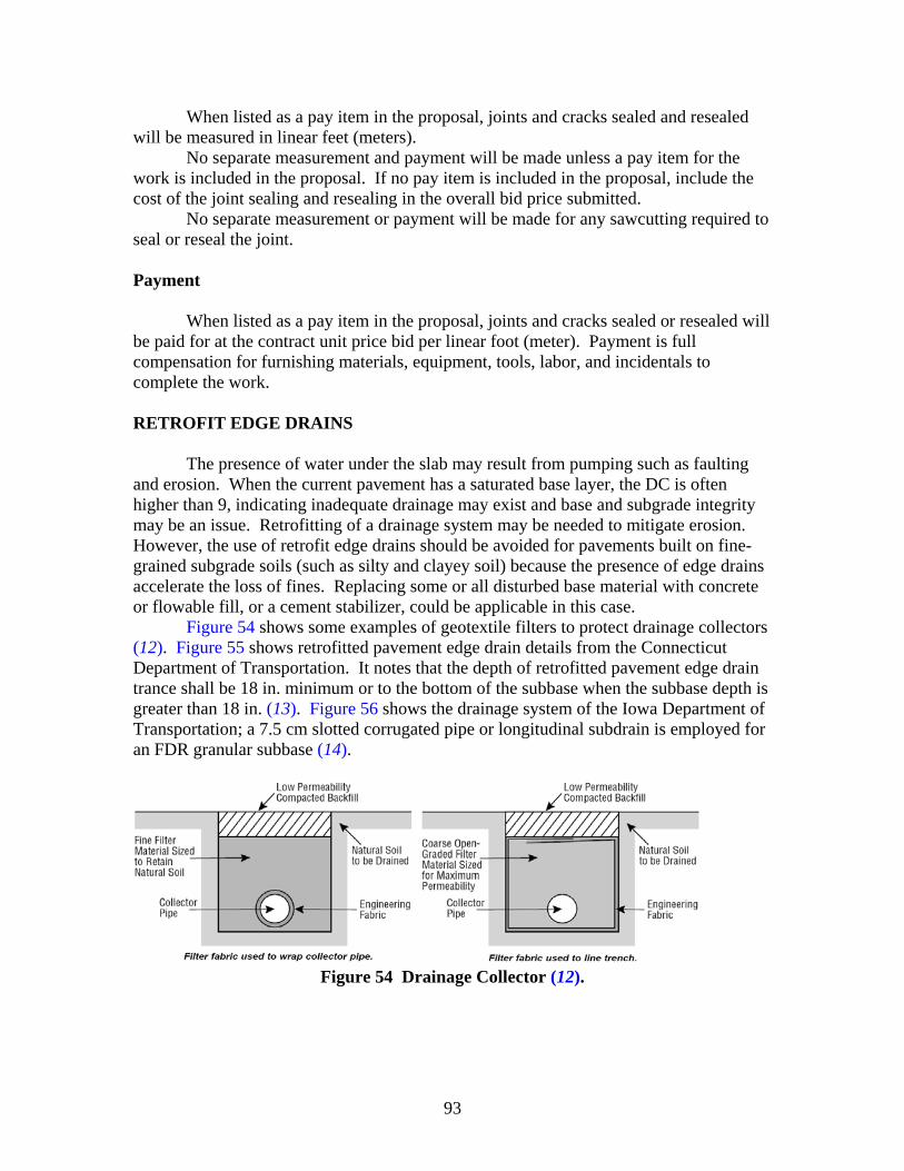
93
When listed as a pay item in the proposal, joints and cracks sealed and resealed will be measured in linear feet (meters).
No separate measurement and payment will be made unless a pay item for the work is included in the proposal. If no pay item is included in the proposal, include the cost of the joint sealing and resealing in the overall bid price submitted.
No separate measurement or payment will be made for any sawcutting required to seal or reseal the joint. Payment When listed as a pay item in the proposal, joints and cracks sealed or resealed will be paid for at the contract unit price bid per linear foot (meter). Payment is full compensation for furnishing materials, equipment, tools, labor, and incidentals to complete the work. RETROFIT EDGE DRAINS
The presence of water under the slab may result from pumping such as faulting and erosion. When the current pavement has a saturated base layer, the DC is often higher than 9, indicating inadequate drainage may exist and base and subgrade integrity may be an issue. Retrofitting of a drainage system may be needed to mitigate erosion. However, the use of retrofit edge drains should be avoided for pavements built on fine-grained subgrade soils (such as silty and clayey soil) because the presence of edge drains accelerate the loss of fines. Replacing some or all disturbed base material with concrete or flowable fill, or a cement stabilizer, could be applicable in this case.
Figure 54 shows some examples of geotextile filters to protect drainage collectors (12). Figure 55 shows retrofitted pavement edge drain details from the Connecticut Department of Transportation. It notes that the depth of retrofitted pavement edge drain trance shall be 18 in. minimum or to the bottom of the subbase when the subbase depth is greater than 18 in. (13). Figure 56 shows the drainage system of the Iowa Department of Transportation; a 7.5 cm slotted corrugated pipe or longitudinal subdrain is employed for an FDR granular subbase (14).
Figure 54 Drainage Collector (12).
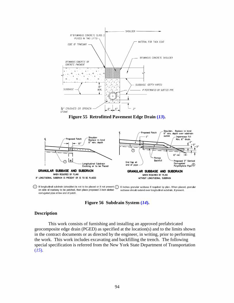
94
Figure 55 Retrofitted Pavement Edge Drain (13).
Figure 56 Subdrain System (14).
Description
This work consists of furnishing and installing an approved prefabricated geocomposite edge drain (PGED) as specified at the location(s) and to the limits shown in the contract documents or as directed by the engineer, in writing, prior to performing the work. This work includes excavating and backfilling the trench. The following special specification is referred from the New York State Department of Transportation (15).

95
Materials General
Provide a geotextile and prefabricated geocomposite edge drain of the type appropriate for the intended use as shown on the plans and as listed in the appropriate Approved List issued by the department’s Materials Bureau. Evaluation of a geotextile or prefabricated geocomposite edge drain not on the Approved List will be made in accordance with procedural directives of the Geotechnical Engineering Bureau. Evaluation will require a minimum of four months.
Provide PGED that is a flexible product consisting of a geotextile bonded to or tightly wrapped around an internal supporting core.
Provide PGED that is resistant to deterioration from salts, road oils, fuels, and other deleterious substances encountered in the type of application. Basis of Acceptance
Geotextiles. The geotextiles that are on the Approved List issued by the department’s Materials Bureau will be accepted on the basis of the brand name labeled on the geotextile or the geotextile container and verification of the geotextile by a departmental geotechnical engineer. Provide a drainage class geotextile conforming to apparent opening size (AOS) Class A and Strength Class 2 or higher.
Prefabricated Geocomposite Edge Drain: The prefabricated geocomposite edge
drains that are on the Approved List issued by the department’s Materials Bureau will be accepted on the basis of the brand name labeled on the drain’s packaging and verification by the engineer of the geotextile wrap being on the Approved List for drainage application for AOS Class A and Strength Class 2 or higher. Quality Assurance of Prefabricated Geocomposite Edge Drain
When the state elects, a 1 m long sample will be obtained for quality assurance testing. The results of this testing will only affect a product’s standing on the Approved List. No payment will be made for this sample. Backfill Material
Provide backfill material meeting the following requirements: • For existing material backfill, provide suitable material. • For underdrain filter material backfill, provide material that meets the
requirements of underdrain filter.

96
Fittings
Provide fittings and materials necessary to make splices and connections of the PGED to outlet piping and that conform to the manufacturer’s requirements. Design all fittings and materials to prevent soil intrusion into the PGED or outlet piping.
Provide fittings that allow for outletting the continuous PGED in a sag area (i.e., a tee) and for outletting the individual run length segments as shown in the contract documents or as ordered by the engineer. In cases where the PGED is terminated without an outlet, provide a fitting to prevent soil intrusion into the end of the PGED. Construction Method
Excavate a trench in the location and to the limits shown in the contract documents or as directed by the engineer. Where existing material backfill is used, place the PGED abutting the side of the trench closest to the centerline of pavement (the inside of the trench). Where underdrain filter material backfill is used, place the PGED abutting the side of the trench farthest away from the centerline of pavement (the outside of the trench). Place the PGED in an upright vertical position so that it has no bends, crimps, or sags in its final position. Be aware that many PGEDs provide drainage on only one side. Place the PGED so the side that provides drainage faces the pavement.
Backfill and compact the trench. Where underdrain filter material backfill is used, place the backfill in one lift. Where existing material backfill is used, place backfill in approximately three equal lifts. For existing material backfill, perform the trenching, PGED placement, and first lift backfill and compaction operations in one continuous operation.
Compact each lift with at least two passes of an approved vibrating pad, plate, or drum-type compactor. Other vibratory compaction systems may be used as approved by the engineer. Remove the surplus excavated material from the work area and dispose of it as required in disposal of surplus excavated materials.
For any given PGED run, install outlets no later than 48 hours after PGED placement. Do not backfill the outlet trench until the installation of the fitting and connection to the outlet pipe is inspected and approved by the engineer. Backfill all trenches before the end of the workday.
Install splices required in the PGED prior to placement of the PGED. Install splices and connections in the PGED in accordance with the manufacturer’s recommendations to ensure continuity of the PGED.
During all periods of shipment and storage, keep the PGED wrapped and protected from direct exposure to sunlight, mud, dirt, and debris. Repair or replace any damaged portion of the PGED to the satisfaction of the engineer. Payment will not be made for repairing or replacing the damaged portions caused by the contractor’s operations.
Backfill and compact all portions of the trench that are overcut in length to facilitate the operation of the trench cutting equipment in accordance with the same requirements as for the trench containing the installed PGED.
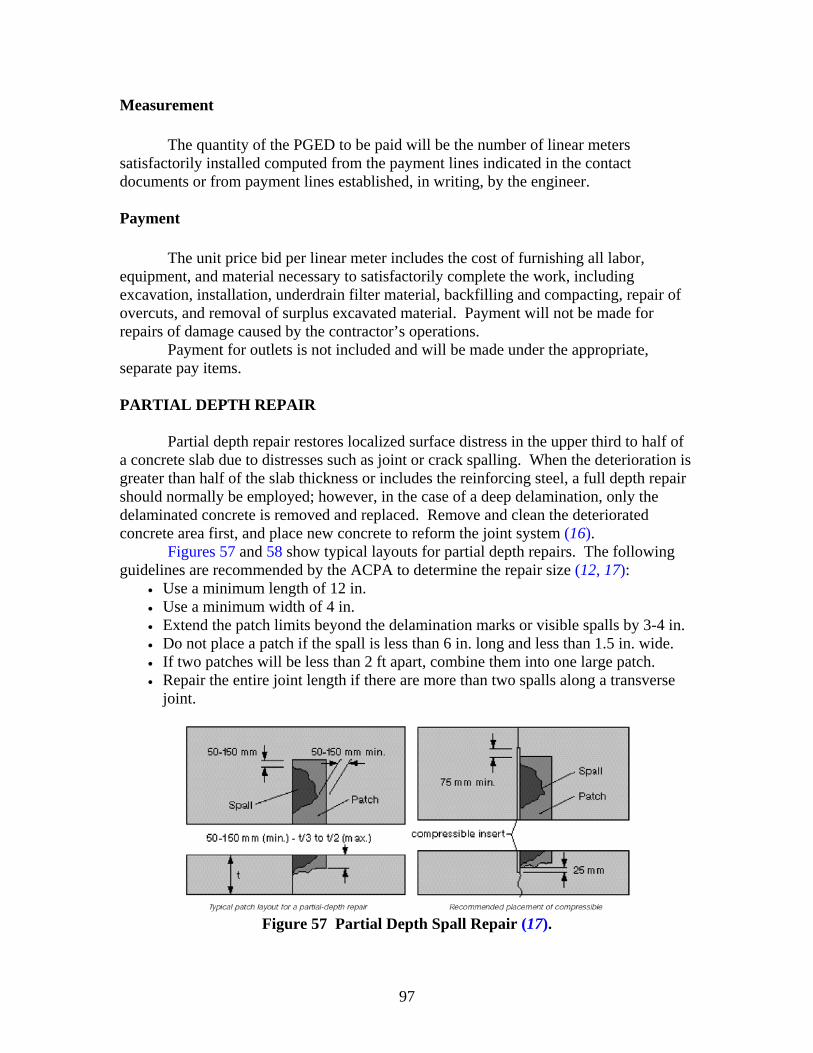
97
Measurement
The quantity of the PGED to be paid will be the number of linear meters satisfactorily installed computed from the payment lines indicated in the contact documents or from payment lines established, in writing, by the engineer. Payment
The unit price bid per linear meter includes the cost of furnishing all labor,
equipment, and material necessary to satisfactorily complete the work, including excavation, installation, underdrain filter material, backfilling and compacting, repair of overcuts, and removal of surplus excavated material. Payment will not be made for repairs of damage caused by the contractor’s operations.
Payment for outlets is not included and will be made under the appropriate, separate pay items. PARTIAL DEPTH REPAIR
Partial depth repair restores localized surface distress in the upper third to half of a concrete slab due to distresses such as joint or crack spalling. When the deterioration is greater than half of the slab thickness or includes the reinforcing steel, a full depth repair should normally be employed; however, in the case of a deep delamination, only the delaminated concrete is removed and replaced. Remove and clean the deteriorated concrete area first, and place new concrete to reform the joint system (16). Figures 57 and 58 show typical layouts for partial depth repairs. The following guidelines are recommended by the ACPA to determine the repair size (12, 17):
• Use a minimum length of 12 in. • Use a minimum width of 4 in. • Extend the patch limits beyond the delamination marks or visible spalls by 3-4 in. • Do not place a patch if the spall is less than 6 in. long and less than 1.5 in. wide. • If two patches will be less than 2 ft apart, combine them into one large patch. • Repair the entire joint length if there are more than two spalls along a transverse
joint.
Figure 57 Partial Depth Spall Repair (17).
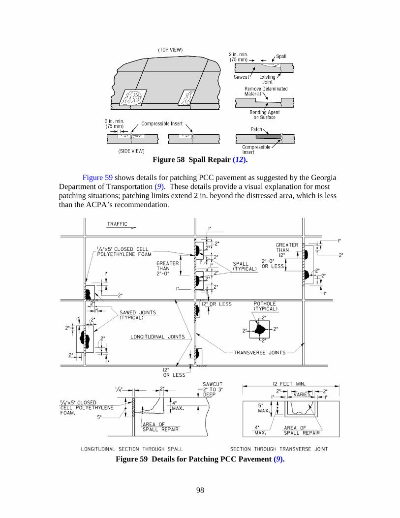
98
Figure 58 Spall Repair (12).
Figure 59 shows details for patching PCC pavement as suggested by the Georgia
Department of Transportation (9). These details provide a visual explanation for most patching situations; patching limits extend 2 in. beyond the distressed area, which is less than the ACPA’s recommendation.
Figure 59 Details for Patching PCC Pavement (9).
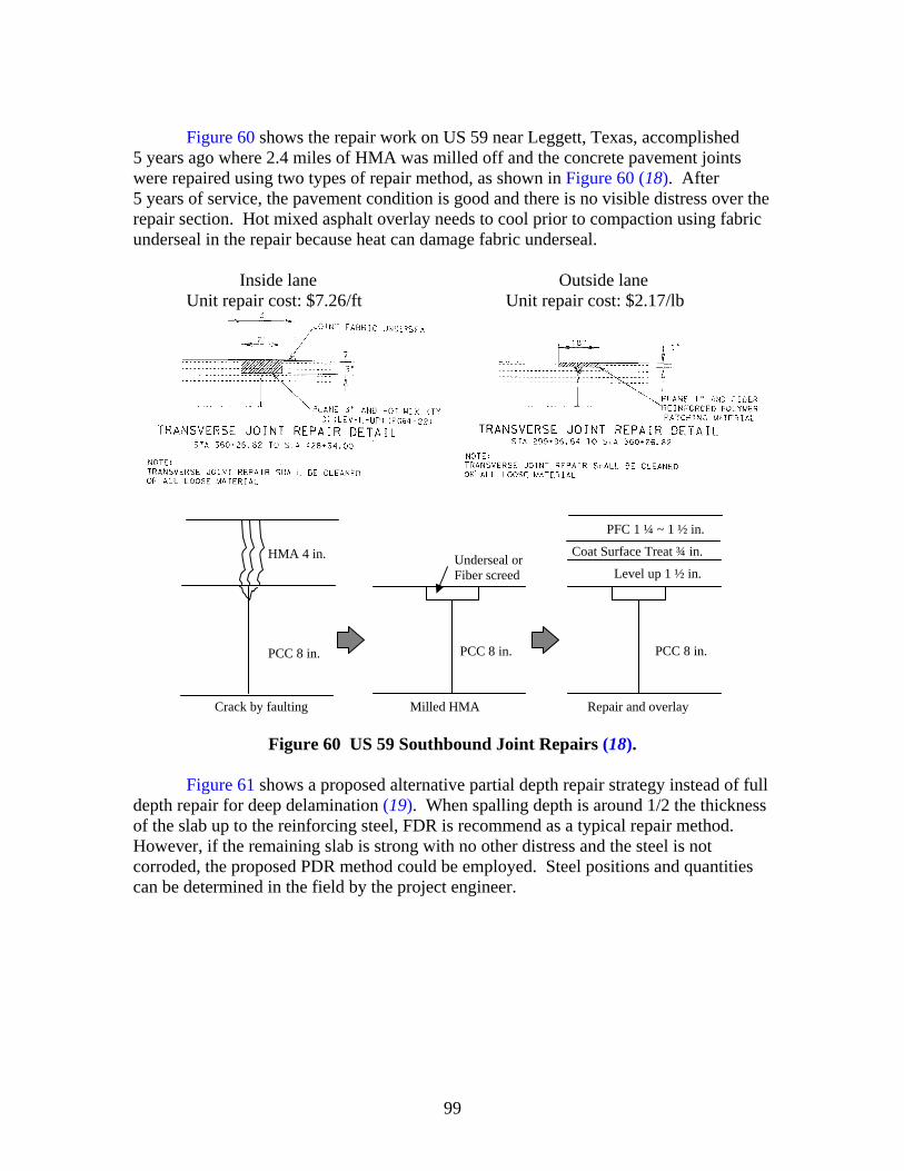
99
Figure 60 shows the repair work on US 59 near Leggett, Texas, accomplished
5 years ago where 2.4 miles of HMA was milled off and the concrete pavement joints were repaired using two types of repair method, as shown in Figure 60 (18). After 5 years of service, the pavement condition is good and there is no visible distress over the repair section. Hot mixed asphalt overlay needs to cool prior to compaction using fabric underseal in the repair because heat can damage fabric underseal.
Inside lane Outside lane
Unit repair cost: $7.26/ft Unit repair cost: $2.17/lb
Figure 60 US 59 Southbound Joint Repairs (18).
Figure 61 shows a proposed alternative partial depth repair strategy instead of full
depth repair for deep delamination (19). When spalling depth is around 1/2 the thickness of the slab up to the reinforcing steel, FDR is recommend as a typical repair method. However, if the remaining slab is strong with no other distress and the steel is not corroded, the proposed PDR method could be employed. Steel positions and quantities can be determined in the field by the project engineer.
PFC 1 ¼ ~ 1 ½ in.
Coat Surface Treat ¾ in.
Level up 1 ½ in.
PCC 8 in.
HMA 4 in.
PCC 8 in. PCC 8 in.
Milled HMA
Underseal or Fiber screed
Repair and overlay Crack by faulting
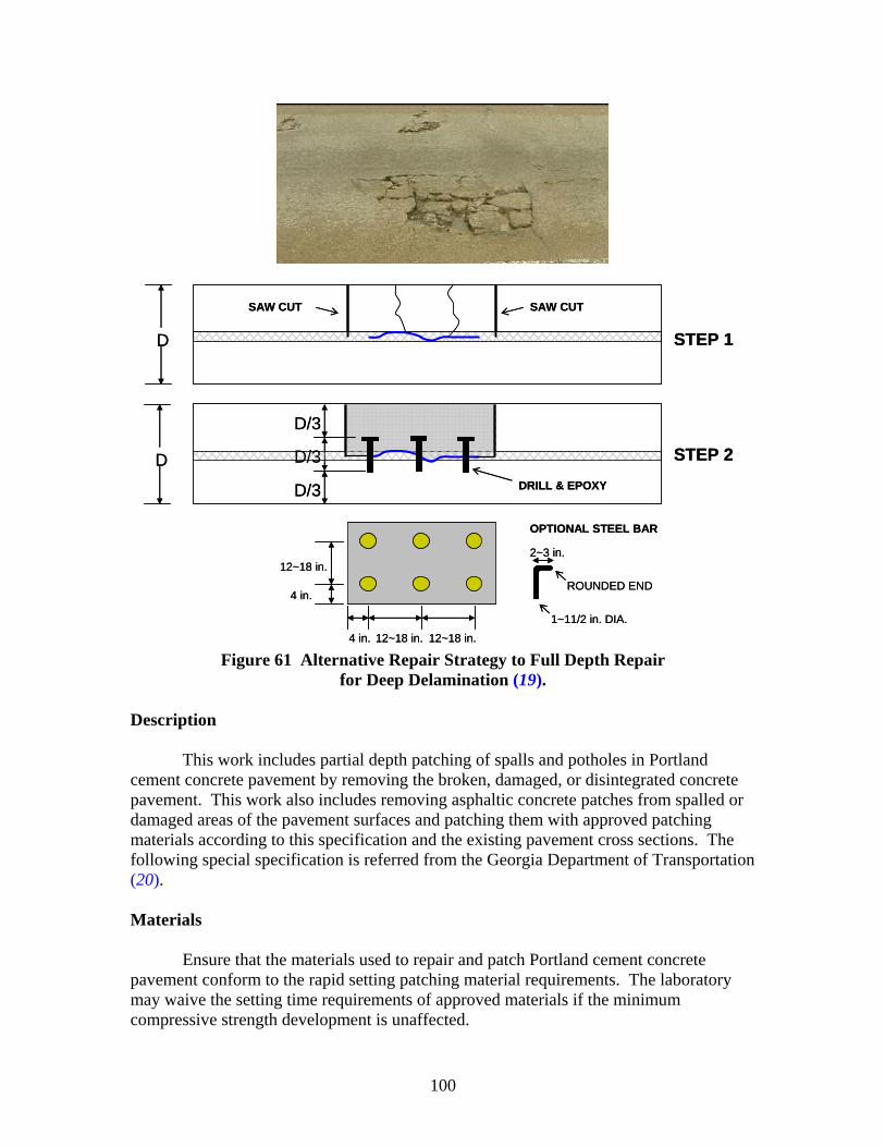
100
12~18 in.
12~18 in.
4 in.
4 in. 12~18 in.
OPTIONAL STEEL BAR
2~3 in.
1~11/2 in. DIA.
ROUNDED END
STEP 2D
D/3
D/3
STEP 1D
D/3DRILL & EPOXY
SAW CUTSAW CUT
12~18 in.
12~18 in.
4 in.
4 in. 12~18 in.
OPTIONAL STEEL BAR
2~3 in.
1~11/2 in. DIA.
ROUNDED END
STEP 2D
D/3
D/3
STEP 1D
D/3DRILL & EPOXY
SAW CUTSAW CUT
Figure 61 Alternative Repair Strategy to Full Depth Repair
for Deep Delamination (19). Description
This work includes partial depth patching of spalls and potholes in Portland cement concrete pavement by removing the broken, damaged, or disintegrated concrete pavement. This work also includes removing asphaltic concrete patches from spalled or damaged areas of the pavement surfaces and patching them with approved patching materials according to this specification and the existing pavement cross sections. The following special specification is referred from the Georgia Department of Transportation (20). Materials
Ensure that the materials used to repair and patch Portland cement concrete pavement conform to the rapid setting patching material requirements. The laboratory may waive the setting time requirements of approved materials if the minimum compressive strength development is unaffected.
101
Equipment
To clean the repair areas, use air compressors equipped with traps that can remove surplus water and oil in the compressed air. Ensure that the compressor can deliver compressed air at a continuous pressure of at least 90 psi (620 kPa).
The engineer will check the compressed air daily for contamination. Do not use contaminated air.
Construction Method Removing and Preparing the Repair Area
Prepare to perform partial patching of spalled joints and potholes as follows.
1. Partial Depth Patching of Spalled Joints. a. “Sound” each transverse joint and longitudinal joint with a visual defect to
determine the limits of the damaged or defective areas. Strike the pavement surface along the sides of each joint with a hammer, chain drag, or similar tool to detect unsound concrete that sounds flat or hollow.
b. Mark the limits of the defective areas on the pavement by making a rectangle 2 in. (50 mm) beyond the outer limits of the unsound concrete area as a guide for sawing.
c. Mark spalled areas less than 2 ft (600 mm) from each other along a joint as one spall area. If separated by 2 ft (600 mm) or more, mark as separate spall areas. Do not repair defective (spalled) joint areas less than 6 in. (150 mm) long and 1.5 in. (40 mm) wide under this specification. Thoroughly clean and seal them with silicone sealant as part of the joint sealing operation.
d. Saw the rectangular marked areas with near vertical faces at least 2 in. (50 mm) but not more than 3 in. (75 mm) deep.
e. Remove unsound material within the sawed area with a maximum 30 lb (135 N) chipping hammer.
f. Do not damage or fracture the sound concrete substrate to be left on the bottom of the spall area. Do not use sharp pointed bits.
g. If the unsound material is more than 4 in. (100 mm) deep, the engineer may direct a 6 ft (1.8 m) slab replacement be placed.
h. Before placing the patching material, saw the face of the existing transverse or longitudinal joints bordering the repair areas. Saw at least 5 in. (125 mm) deep and 0.25 in. (6 mm) wide with the full depth of the sawcut extending at least 1 in. (25 mm) beyond the limits of the repair areas in each direction.
i. Immediately before placing the patching material, thoroughly clean the surfaces within the repair areas by sandblasting and air blasting to remove oil, dust, dirt, traces of asphaltic concrete, slurry from saw operation, and other contaminants.
j. Place a 0.25 in. (6 mm) wide piece of closed-cell polyethylene foam shaped to fit the sawcut in the joints bordering the repair areas. If “back-to-back”
102
repairs are made at a joint, support the 0.25 in. (6 mm) closed-cell polyethylene foam during the placing operation to maintain a true, straight joint line. Have the engineer approve the method used. The polyethylene foam must be supported in a straight line when the patching material is placed so a straight joint line will be formed. Maintain a straight line or the engineer may require the repairs be repeated at no additional cost to the department.
2. Partial Depth Patching of Pavement Potholes. The engineer will determine
which pavement potholes will be repaired. Use the procedures given for repairing spalled joints to repair potholes within the pavement surface. The requirement of using the 0.25 in. (6 mm) closed-cell polyethylene foam does not apply.
Concrete Patching
Patch concrete one lane at a time, safely and rapidly to minimize inconvenience to the traveling public.
1. Accomplish the work with other operations in progress within an area if possible. 2. Complete the work before the grinding operation begins if grinding is specified. 3. Remove and replace completed concrete patches that contain cracks, shrinkage,
compression failures, or are damaged by construction or traffic before final acceptance at no additional cost to the department.
Placing Patching Material
Use Repair Method 1 unless the state materials research engineer gives written approval to use Repair Method 2. Use Repair Method 1 when the average daily temperature is 50 ºF (10 ºC) or above. Use of Repair Method 2, if approved, is limited to the manufacturer’s written recommendations.
For the following repair methods, begin the placement when the surface within the repair area is dry and thoroughly free of contaminants. Ensure that the finished surface including joints meets a surface tolerance of 1/8 in. (3 mm) per 10 ft (3 m). Use approved measures as necessary to keep pavement surfaces adjacent to this operation free of excess grout and other materials. Unless otherwise specified, complete the patching operations and open the lanes to traffic before sunset each day.
1. Repair Method 1. For 24 hour accelerated strength concrete, use this method as
follows: a. Completely coat the concrete surface areas within the repair area with a film
of Type II epoxy approximately 10 to 20 mils (0.25 to 0.50 mm) thick. b. Mix the concrete on site in a portable mixer. Obtain approval for the mix
design and mixing method from the laboratory. The material must meet a slump range of 1.0 in. (25 mm) to 3.0 in. (75 mm).
c. Deposit the concrete in the repair area while the epoxy is still tacky. Vibrate it to form a dense, homogeneous mass of concrete that completely fills the patch area.
103
d. Screed the concrete to the proper grade and do not disturb it until the water sheen disappears from the surface.
e. Cover the concrete with wet burlap or membrane curing compound. Allow the curing to continue for at least three hours. The engineer may require longer curing to ensure sufficient concrete strength development before opening to traffic.
2. Repair Method 2. For rapid setting patching material for Portland cement
concrete pavement: a. In addition to the requirements outlined in “Removing and Preparing the
Repair Area,” prepare the surfaces in the repair areas according to the manufacturer’s written recommendations.
b. Perform the patching material handling, mixing, placing, consolidating, screeding, and curing according to the manufacturer’s written instructions as approved by the laboratory.
c. Continue curing for at least 1 hour and until opening the section to traffic. Special Requirements
The following special requirements apply to this work: 1. If repairing adjacent to an unstable shoulder, place a form the full depth of the
repair area to maintain a true, straight shoulder joint and to prevent the patching material from intruding onto the shoulder area.
2. After curing the patching material, remove the form and repair the shoulder at no cost to the department.
3. During sandblasting, protect traffic in the adjacent lanes. 4. After the sandblasting operations:
a. Thoroughly clean the area to be repaired with compressed air. b. Remove sand from the sandblasting operation from the roadway and
shoulders. 5. Do not “over-cut” the pavement beyond marked areas whenever possible. 6. Remove saw slurry and other contaminates from the over-cutting. 7. Repair the over-cuts by filling full depth with an approved low-viscosity epoxy
compound using a Type II epoxy adhesive. Make these repairs as soon as possible, but not after the joint is resealed.
8. Re-establish original transverse and longitudinal joints by sawing and sealing the joints with silicone that meets the requirements of the plan details. Re-establish the joints within 60 days after placing the patch. Ensure that re-established joints are at least 3/8 in. (10 mm) wide.
Measurement
The area measured for payment is the number of square yards (meters) of patching complete in place and accepted.
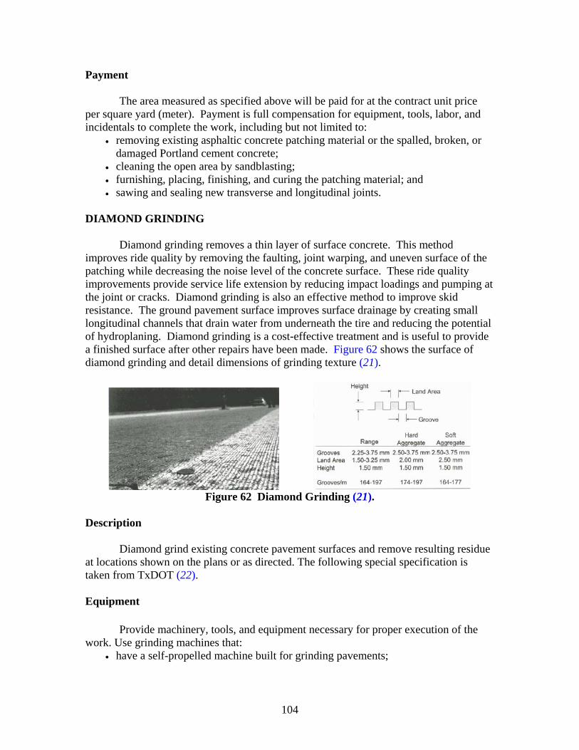
104
Payment
The area measured as specified above will be paid for at the contract unit price per square yard (meter). Payment is full compensation for equipment, tools, labor, and incidentals to complete the work, including but not limited to:
• removing existing asphaltic concrete patching material or the spalled, broken, or damaged Portland cement concrete;
• cleaning the open area by sandblasting; • furnishing, placing, finishing, and curing the patching material; and • sawing and sealing new transverse and longitudinal joints.
DIAMOND GRINDING
Diamond grinding removes a thin layer of surface concrete. This method improves ride quality by removing the faulting, joint warping, and uneven surface of the patching while decreasing the noise level of the concrete surface. These ride quality improvements provide service life extension by reducing impact loadings and pumping at the joint or cracks. Diamond grinding is also an effective method to improve skid resistance. The ground pavement surface improves surface drainage by creating small longitudinal channels that drain water from underneath the tire and reducing the potential of hydroplaning. Diamond grinding is a cost-effective treatment and is useful to provide a finished surface after other repairs have been made. Figure 62 shows the surface of diamond grinding and detail dimensions of grinding texture (21).
Figure 62 Diamond Grinding (21).
Description
Diamond grind existing concrete pavement surfaces and remove resulting residue at locations shown on the plans or as directed. The following special specification is taken from TxDOT (22). Equipment
Provide machinery, tools, and equipment necessary for proper execution of the
work. Use grinding machines that: • have a self-propelled machine built for grinding pavements;
105
• provide enough power, traction, and stability to maintain specified depth of cut and cross slope (do not use flailing devices);
• have 50 to 60 diamond blades per foot, mounted on a multi-blade arbor; • have approved dual longitudinal controls capable of operating on both sides
automatically from any longitudinal grade reference, which includes string line, ski, mobile string line, or matching shoe;
• have approved transverse controls with an automatic system to control cross slope at a given rate; and
• are able to achieve a uniform depth of cut, flush to all inlets, manholes, bridge joints, and other appurtenances within the paved area.
Construction Method
Demonstrate grinding work to receive approval of the operation procedure and the
use of grinding and residue-removing equipment. Grinding
Perform grinding in a longitudinal direction beginning and ending at lines perpendicular to the pavement lane lines. Start grinding at the outside edge of the concrete pavement, and continue across the lane surface to the opposite outer edge of the traffic lane or pavement. Grind surfaces on both sides of transverse joints or cracks and finish the surfaces in essentially the same plane. Eliminate minor depressions by extra depth grinding when directed. Transition auxiliary and ramp lane grinding from the main lane edge as directed. Terminate grinding at bridge joints.
Produce a uniform surface with a longitudinal corduroy type texture that eliminates joint and crack faults. Provide positive lateral surface drainage by maintaining a constant cross slope across each lane. Grooves
Groove 0.10 to 0.16 in. wide with a land area 0.70 to 0.80 in. between the
grooves. Groove to the specified depth as shown on the plans. Meet the groove tolerances ± 0.02 in. for width and ± 0.06 in. for depth under normal pavement conditions unless otherwise directed. Repairs
Repair damages to concrete pavement caused by contractor’s operation without
any additional compensation. As directed, perform repairs in accordance with Item 361, “Full-Depth Repair of Concrete Pavement,” or Item 720, “Repair of Spalling in Concrete Pavement,” if spalls are 0.25 to 3 in. depth.
106
Ride Quality Unless otherwise shown on the plans, measure ride quality in accordance with
Item 585, “Ride Quality for Pavement Surfaces.” Removal of Residue
Immediately and continuously remove the slurry or residue resulting from the grinding operation. Keep pavement in a washed clean condition and free of slipperiness from the slurry, etc. Do not permit the residue to flow across shoulders or lanes occupied by traffic or into gutters or other drainage facilities.
Measurement
This Item will be measured by the square yard of surface area grinded and
accepted. Measurement will be based on the depth shown, within the limits shown on the plans. Payment
The work performed and materials furnished in accordance with this Item and
measured as provided under “Measurement” will be paid for at the unit price bid for “Diamond Grinding Concrete Pavement,” of the depth specified. This price is full compensation for grinding the pavement surface, repairing of damaged concrete pavement including spalls or partial depth failures, loading, hauling, and disposing of the residue material, labor, tools, equipment, and incidentals. Demonstration work to receive approval for use of equipment will not be paid for unless work is performed in accordance with the contract and is accepted.
RETROFIT LOAD TRANSFER
When a pavement shows spalling, faulting, and pumping at joints or transverse cracks, the load transfer efficiency could be suspect because the LTE of a joint could be diminished by repeated heavy loads. When the LTE at the joint is lower than 70 percent, dowel bar retrofitting (with slab stabilization if voids are detected) should be employed at the joint or crack to increase the load transfer efficiency between slabs. The better the load transfer efficiency, the better the structural capacity of the joint or crack and the lower the deflection-related faulting and corner cracking.
Dowel bars are retrofit into Kerf cuts in the pavement surface across the joint or crack. The slots should be cleaned before dowel placement and backfilled after dowel bar placement (23, 24). Figures 63 and 64 show load transfer repair details used by the California Department of Transportation (Caltrans) and Washington State Department of Transportation (WSDOT)(25, 26).
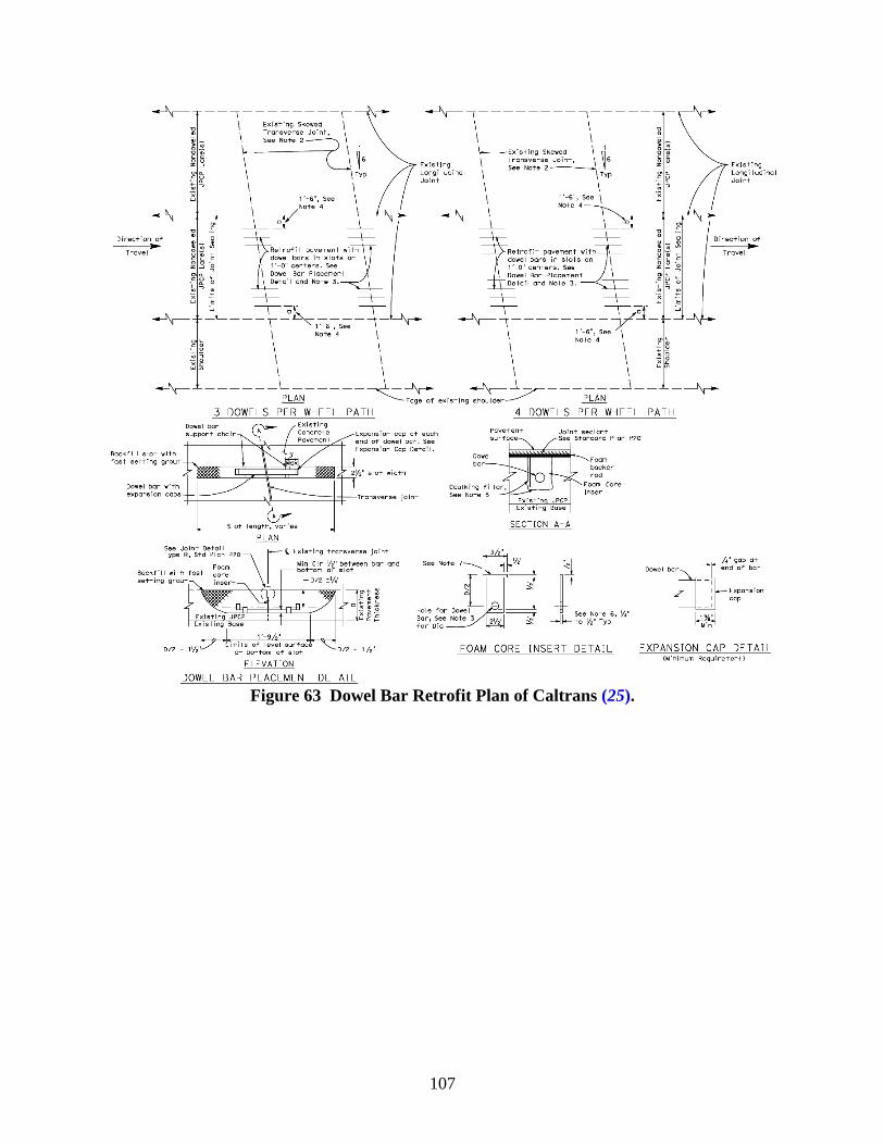
107
Figure 63 Dowel Bar Retrofit Plan of Caltrans (25).
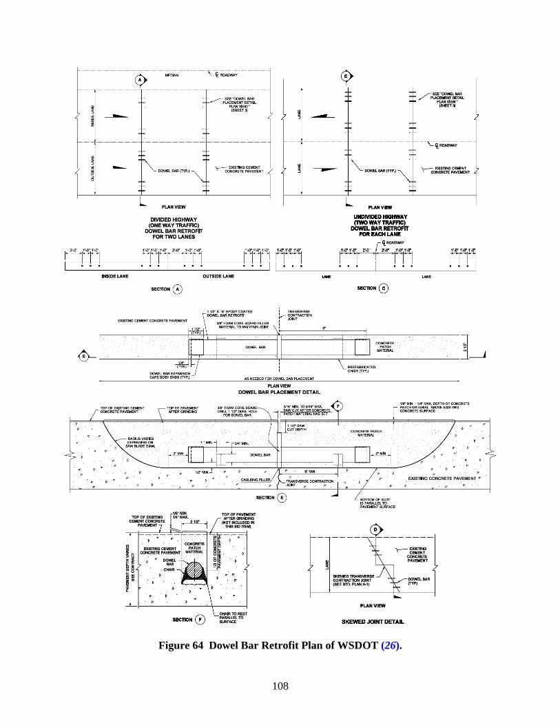
108
Figure 64 Dowel Bar Retrofit Plan of WSDOT (26).
109
Description
This work shall consist of cutting slots at transverse cracks, placing dowel bars in the slots, and filling the void with a concrete patching material. All work shall conform to details as shown on the plans. The following special specification is referred from the Michigan Department of Transportation (27). Materials
Dowel bars shall be 18 in. (460 mm) long and 1½ in. (38 mm) in diameter. They shall be epoxy coated, or encased in a sleeve, except that the epoxy coating or sleeve shall be the full length of the dowel bar.
Expansion caps shall be made of plastic as approved by the engineer and of the dimensions shall have a 1½ in. (38 mm) inside diameter, and shall provide a minimum of ½ in. (13 mm) of expansion space beyond the end of the dowel bar if using only one cap. If an expansion cap is used on each end of the dowel bar, each cap shall provide a minimum of ¼ in. (7 mm) of expansion space.
Bond release agent for the dowel bars shall be selected from the Qualified Products List (QPL) for Coatings for Dowel Bar.
Dowel bar chairs shall be made of either a non-metallic material or an epoxy-coated metallic material as approved by the engineer.
Material used to re-form the crack shall be able to be cut to the width of slot +¼ in./–0 in. (+6 mm/–0 mm), fit around the dowel bar, and be a minimum of ¼ in. (6 mm) below the existing pavement surface. It shall be of a continuous, one-piece, smooth compressible material and shall be a maximum of ¼ in. (6 mm) thick. It shall also be semi-rigid such that it will not bend or fold over when the patching material is placed. Rubber materials will not be allowed unless it can be demonstrated to the engineer that they can withstand bending or folding.
Bond breaker tape or joint sealant for sealing the crack shall be selected from the Qualified Products List. The bond breaker tape shall be selected from the Qualified Products List for Bond Breaker Tapes. The joint sealant shall be selected from the Qualified Products List for Sealant for Perimeter of Beam Repairs.
Concrete patching materials used to backfill the slots shall be selected from the Qualified Products List for Prepackaged Hydraulic Fast-Set Patching. The patching material shall be extended with aggregate up to the maximum amount specified in the QPL. If a curing compound is recommended by the manufacturer of the patching material, it shall be in accordance with Standard Specifications for Construction.
The aggregate used in the patching materials shall be a dry, clean, crushed 26A gradation conforming to Standard Specifications for Construction, or equivalent as approved by the engineer.
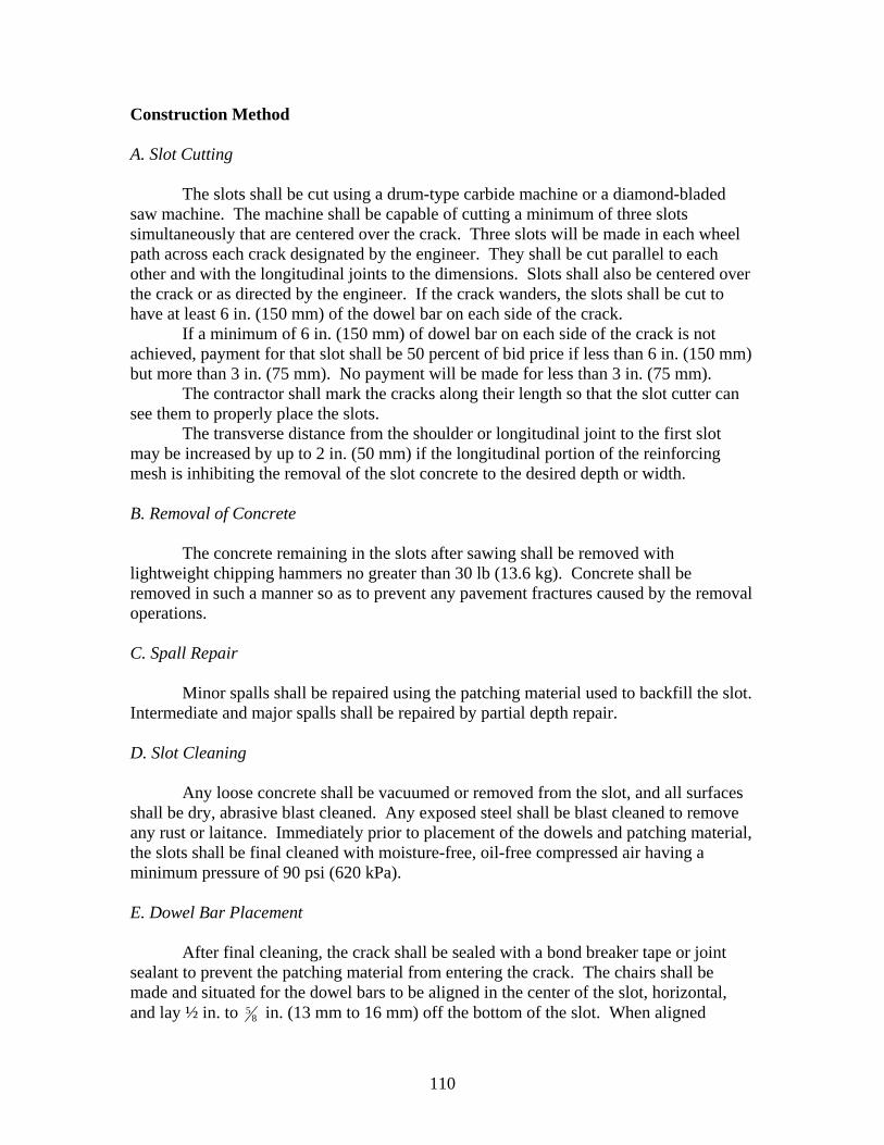
110
Construction Method A. Slot Cutting
The slots shall be cut using a drum-type carbide machine or a diamond-bladed saw machine. The machine shall be capable of cutting a minimum of three slots simultaneously that are centered over the crack. Three slots will be made in each wheel path across each crack designated by the engineer. They shall be cut parallel to each other and with the longitudinal joints to the dimensions. Slots shall also be centered over the crack or as directed by the engineer. If the crack wanders, the slots shall be cut to have at least 6 in. (150 mm) of the dowel bar on each side of the crack.
If a minimum of 6 in. (150 mm) of dowel bar on each side of the crack is not achieved, payment for that slot shall be 50 percent of bid price if less than 6 in. (150 mm) but more than 3 in. (75 mm). No payment will be made for less than 3 in. (75 mm).
The contractor shall mark the cracks along their length so that the slot cutter can see them to properly place the slots.
The transverse distance from the shoulder or longitudinal joint to the first slot may be increased by up to 2 in. (50 mm) if the longitudinal portion of the reinforcing mesh is inhibiting the removal of the slot concrete to the desired depth or width. B. Removal of Concrete
The concrete remaining in the slots after sawing shall be removed with lightweight chipping hammers no greater than 30 lb (13.6 kg). Concrete shall be removed in such a manner so as to prevent any pavement fractures caused by the removal operations. C. Spall Repair
Minor spalls shall be repaired using the patching material used to backfill the slot. Intermediate and major spalls shall be repaired by partial depth repair. D. Slot Cleaning
Any loose concrete shall be vacuumed or removed from the slot, and all surfaces shall be dry, abrasive blast cleaned. Any exposed steel shall be blast cleaned to remove any rust or laitance. Immediately prior to placement of the dowels and patching material, the slots shall be final cleaned with moisture-free, oil-free compressed air having a minimum pressure of 90 psi (620 kPa). E. Dowel Bar Placement
After final cleaning, the crack shall be sealed with a bond breaker tape or joint sealant to prevent the patching material from entering the crack. The chairs shall be made and situated for the dowel bars to be aligned in the center of the slot, horizontal, and lay ½ in. to 8
5 in. (13 mm to 16 mm) off the bottom of the slot. When aligned
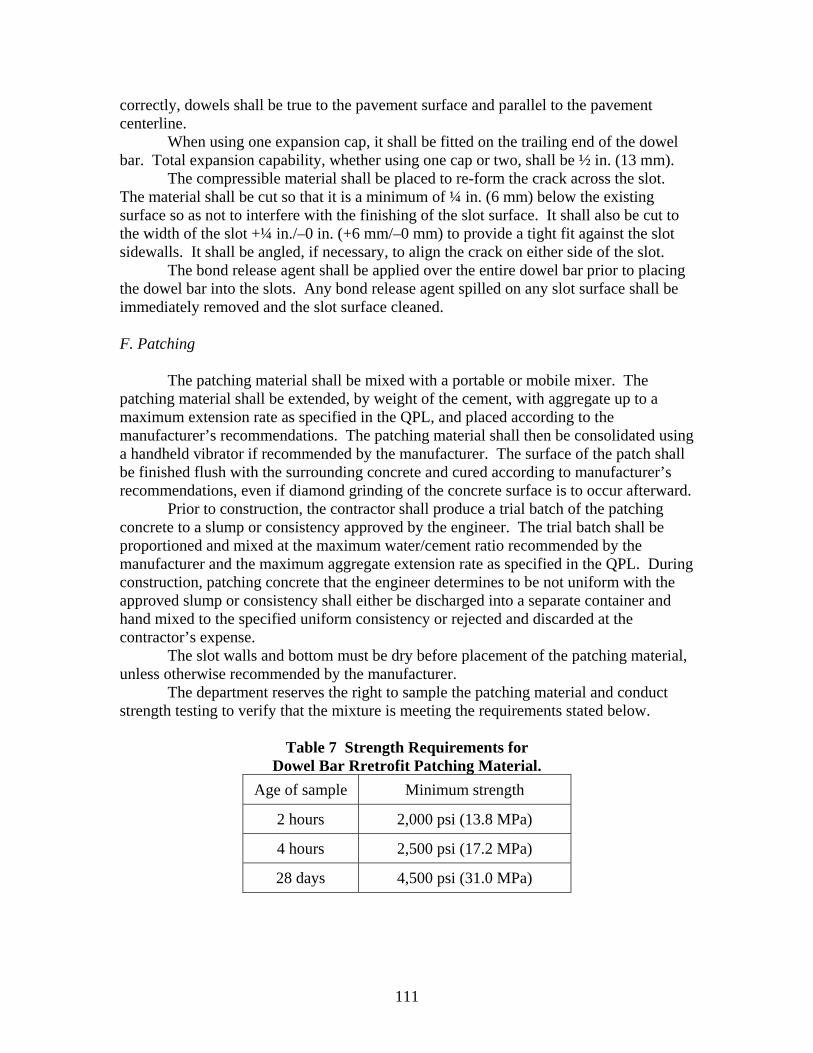
111
correctly, dowels shall be true to the pavement surface and parallel to the pavement centerline.
When using one expansion cap, it shall be fitted on the trailing end of the dowel bar. Total expansion capability, whether using one cap or two, shall be ½ in. (13 mm).
The compressible material shall be placed to re-form the crack across the slot. The material shall be cut so that it is a minimum of ¼ in. (6 mm) below the existing surface so as not to interfere with the finishing of the slot surface. It shall also be cut to the width of the slot +¼ in./–0 in. (+6 mm/–0 mm) to provide a tight fit against the slot sidewalls. It shall be angled, if necessary, to align the crack on either side of the slot.
The bond release agent shall be applied over the entire dowel bar prior to placing the dowel bar into the slots. Any bond release agent spilled on any slot surface shall be immediately removed and the slot surface cleaned. F. Patching
The patching material shall be mixed with a portable or mobile mixer. The patching material shall be extended, by weight of the cement, with aggregate up to a maximum extension rate as specified in the QPL, and placed according to the manufacturer’s recommendations. The patching material shall then be consolidated using a handheld vibrator if recommended by the manufacturer. The surface of the patch shall be finished flush with the surrounding concrete and cured according to manufacturer’s recommendations, even if diamond grinding of the concrete surface is to occur afterward.
Prior to construction, the contractor shall produce a trial batch of the patching concrete to a slump or consistency approved by the engineer. The trial batch shall be proportioned and mixed at the maximum water/cement ratio recommended by the manufacturer and the maximum aggregate extension rate as specified in the QPL. During construction, patching concrete that the engineer determines to be not uniform with the approved slump or consistency shall either be discharged into a separate container and hand mixed to the specified uniform consistency or rejected and discarded at the contractor’s expense.
The slot walls and bottom must be dry before placement of the patching material, unless otherwise recommended by the manufacturer.
The department reserves the right to sample the patching material and conduct strength testing to verify that the mixture is meeting the requirements stated below.
Table 7 Strength Requirements for
Dowel Bar Rretrofit Patching Material. Age of sample Minimum strength
2 hours 2,000 psi (13.8 MPa)
4 hours 2,500 psi (17.2 MPa)
28 days 4,500 psi (31.0 MPa)
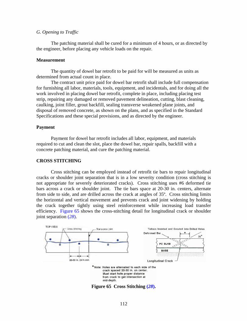
112
G. Opening to Traffic
The patching material shall be cured for a minimum of 4 hours, or as directed by the engineer, before placing any vehicle loads on the repair. Measurement
The quantity of dowel bar retrofit to be paid for will be measured as units as determined from actual count in place.
The contract unit price paid for dowel bar retrofit shall include full compensation for furnishing all labor, materials, tools, equipment, and incidentals, and for doing all the work involved in placing dowel bar retrofit, complete in place, including placing test strip, repairing any damaged or removed pavement delineation, cutting, blast cleaning, caulking, joint filler, grout backfill, sealing transverse weakened plane joints, and disposal of removed concrete, as shown on the plans, and as specified in the Standard Specifications and these special provisions, and as directed by the engineer. Payment
Payment for dowel bar retrofit includes all labor, equipment, and materials required to cut and clean the slot, place the dowel bar, repair spalls, backfill with a concrete patching material, and cure the patching material.
CROSS STITCHING
Cross stitching can be employed instead of retrofit tie bars to repair longitudinal cracks or shoulder joint separation that is in a low severity condition (cross stitching is not appropriate for severely deteriorated cracks). Cross stitching uses #6 deformed tie bars across a crack or shoulder joint. The tie bars space at 20-30 in. centers, alternate from side to side, and are drilled across the crack at angles of 35º. Cross stitching limits the horizontal and vertical movement and prevents crack and joint widening by holding the crack together tightly using steel reinforcement while increasing load transfer efficiency. Figure 65 shows the cross-stitching detail for longitudinal crack or shoulder joint separation (28).
Figure 65 Cross Stitching (28).
113
Description
This work consists of cross stitching longitudinal cracks in concrete pavement by
epoxying deformed tie bars across the pavement crack in accordance with plan details and following requirements. The following special specification is taken from the Louisiana Department of Transportation (29). Materials Deformed Tie Bars
Tie bars used for cross stitching shall be epoxy-coated deformed bars. Epoxy Coating
Epoxy coating for dowel bars and tie bars shall conform to AASHTO M284, except that the thickness of the cured coating shall be 10 +/– 2 mils. Drills
Use a hydraulic drill with tungsten carbide bits. Control the forward and reverse travel of the drill by mechanically applied pressure. Mount the drill on a suitable piece of equipment such that it is quickly transported and positioned. Rest and reference the drill rig frame on and to the pavement surface such that the drilled holes are cylindrical and repeatable in terms of position and alignment on the surface being drilled. Handheld drills are not permitted.
Construction Method
Angled holes shall be drilled on each side of the longitudinal crack at the spacing shown on the plans. The contractor will be required to drill shallow, vertical starter holes at each tie bar location if the angle drill spalls the pavement surface at the start of drilling operations.
The holes shall be blown out with compressed air and shall be dry prior to filling with epoxy. The air compressor shall be equipped with an approved oil and water trap. Holes shall be filled with a Type 1, Grade C epoxy system.
The color of the epoxy system shall approximate that of the concrete pavement. The epoxy shall be mixed in accordance with the manufacturer’s recommendations and injected into the hole using a caulking gun or other approved method. Epoxy injected shall be sufficient to fill the void between the bar and hole as evidenced by epoxy squeeze-out when the bar is inserted. The top of the reinforcing bar shall be below the pavement surface, and excess epoxy shall be removed flush with the surface of the pavement. Epoxy shall not be applied when the ambient temperature is below 40 °F.
After the tie bars have been placed and the epoxy has cured, the random crack shall be routed to a minimum depth of 3/4 in. (20 mm) and to a width of not less than 3/8 in. (10 mm) or more than 5/8 in. (16 mm). The crack shall be sealed with a silicone
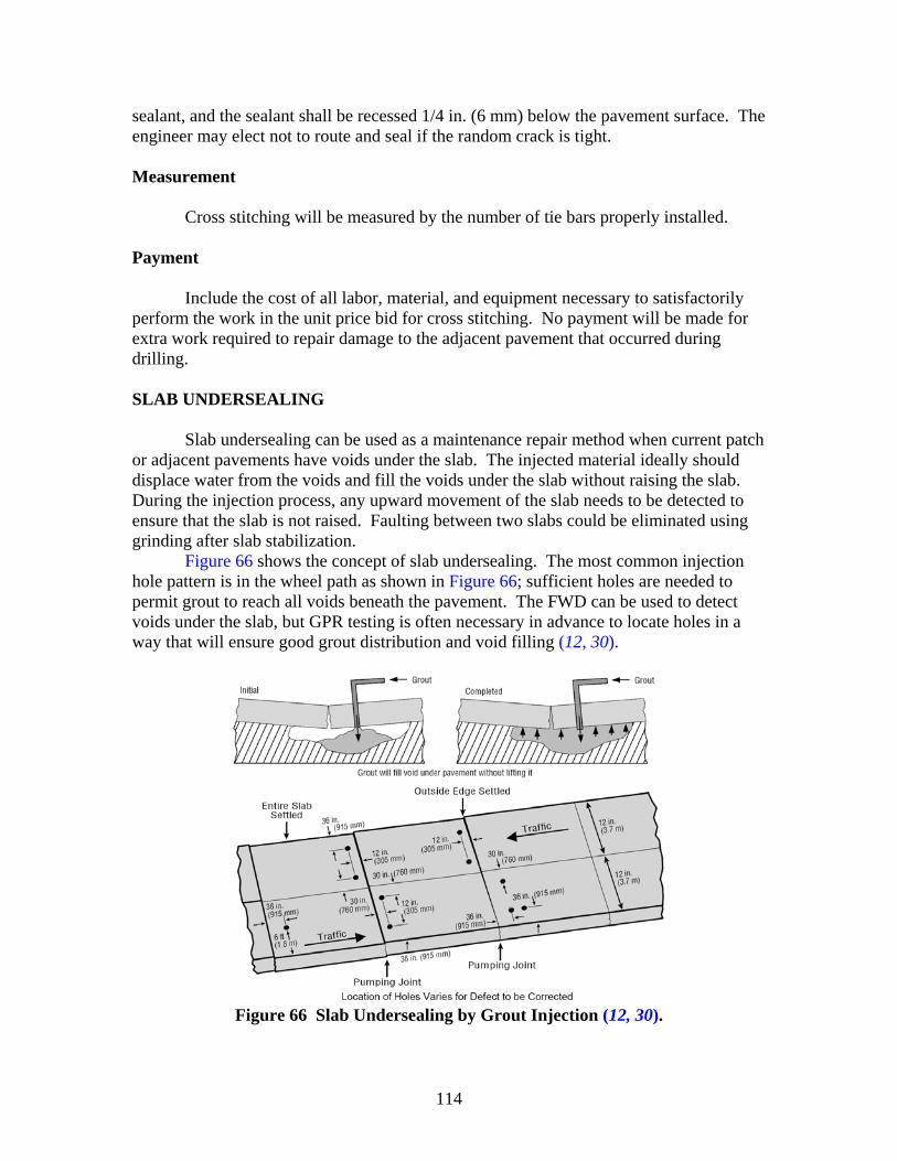
114
sealant, and the sealant shall be recessed 1/4 in. (6 mm) below the pavement surface. The engineer may elect not to route and seal if the random crack is tight. Measurement
Cross stitching will be measured by the number of tie bars properly installed. Payment
Include the cost of all labor, material, and equipment necessary to satisfactorily perform the work in the unit price bid for cross stitching. No payment will be made for extra work required to repair damage to the adjacent pavement that occurred during drilling.
SLAB UNDERSEALING
Slab undersealing can be used as a maintenance repair method when current patch or adjacent pavements have voids under the slab. The injected material ideally should displace water from the voids and fill the voids under the slab without raising the slab. During the injection process, any upward movement of the slab needs to be detected to ensure that the slab is not raised. Faulting between two slabs could be eliminated using grinding after slab stabilization.
Figure 66 shows the concept of slab undersealing. The most common injection hole pattern is in the wheel path as shown in Figure 66; sufficient holes are needed to permit grout to reach all voids beneath the pavement. The FWD can be used to detect voids under the slab, but GPR testing is often necessary in advance to locate holes in a way that will ensure good grout distribution and void filling (12, 30).
Figure 66 Slab Undersealing by Grout Injection (12, 30).
115
Description
Raise and underseal concrete slabs at locations shown on the plans and as directed. The following special specification is referred from TxDOT (31). Materials
Furnish high density polyurethane material, such as URETEK 486 or an approved equivalent. Use epoxy material that meets the requirements of DMS-6100, “Epoxies and adhesives,” Type III Class B. Equipment
Provide machinery, tools, and equipment necessary for proper execution of the work. A. Drill
Use a maximum 40 lb drill capable of drilling 1/2 in. or 5/8 in. diameter holes.
B. Pump
Furnish a pump unit with a pressure gage and that is capable of injecting the polyurethane:
• between the concrete slab and subbase, and • controlling the rate of the rise of the concrete slab.
Construction Methods A. Preparation
Prepare a profile of each area to determine the extent of the concrete slab that requires adjustment or raising. Ensure that the finished concrete slabs will conform to the grades and cross section of the slabs prior to settlement and following the settlement. Determine the exact locations of the injection holes at 3 to 6 ft intervals for each treated area. Obtain approval for the final proposed grades and the injection holes. B. Drilling
Use drilling operations that do not damage the surrounding concrete. Drill a series of 1/2 in. or 5/8 in. injection holes through the concrete as proposed or as directed. C. Injection
Inject high density polyurethane formulation directly under the slab. Do not extend the nozzle end below the bottom of the concrete. Control the rise of the slab by
116
regulating the rate of injection and by controlling the pumping unit. Do not overfill the voids under the slabs. Keep pumping pressure below 200 psi unless otherwise directed by the engineer. Cease injection at a particular location when the engineer determines that continued injection is no longer feasible due to major voids. Take precautions to prevent the injected material from going into any drainage facility and other structures.
Remove any excessive polyurethane material after the nozzle is removed from the hole. Seal the hole with an approved method and material. D. Grade Control
Control the final elevations within 1/4 in. of the proposed profile elevations. The engineer may check the treated area to confirm that the pavement has been aligned properly to facilitate drainage. E. Repairs
As directed, repair any pavement slab or bridge approach slab that is cracked, or that has excessive lifting or where the slab is left uneven, that is the result of the contractor’s operation without any additional compensation. F. Set Time
Formulate the high density polyurethane to set and obtain 90 percent of its compressive strength within 15 minutes after injection. Attain manufacturer’s recommended compressive strength unless otherwise shown on the plans. Measurement
This Item will be measured by the pound of high density polyurethane injected and accepted. Payment
The work performed and materials furnished in accordance with this Item and measured as provided under “Measurement” will be paid for at the unit price bid for “Raising and Undersealing Concrete Slabs.” This price is full compensation for furnishing and injecting material, all labor, materials, tools, and incidentals.
FULL DEPTH REPAIR
Full depth repairs involve replacing a portion of slab with new concrete. When other maintenance repair methods are not appropriate, full depth repair must be employed. When repair boundaries are decided, sawcut boundaries delineate where the old concrete will be removed before replacing with new concrete. Each repair must be large enough to minimize future problems, minimizing the patching material. The

117
patching width is normally the same as the lane width, but often half a lane width is recommended.
After the old concrete material has been removed, the base course should be examined and all of the disturbed material removed and the patch area recompacted. Replacing some or all disturbed base material (modulus is less than 10 ksi based on backcalculation of DCP testing, or PR is higher than 1 in./blow) with concrete or flowable fill may be the best alternative since it is difficult to adequately compact granular material inside a patch. If proper compaction is not achieved, the base will settle and a void will develop under the slab.
If an untreated base contains a high percentage of fines (30 to 40 percent) and wet conditions, the modulus and general performance can be improved by adding low levels (2 to 4 percent) of cement stabilizer. This cement stabilizer is also effective in improving wet subgrade soils. However, if excessive moisture exists in the repair area, it should be removed or dried before replacing. Grinding after FDR is necessary to remove uneven surfaces after patching, which may improve ride quality and extend service life by reducing impact loadings at the joint.
Figure 67 shows the patching patterns and general idea of the transverse and longitudinal joint type in various PCC pavement repair configurations (32). Figure 68 shows the full depth repair detail used by TxDOT, and Figure 69 shows the tied and contraction joint detail for full depth repair used by the Michigan Department of Transportation (33, 34).
Figure 67 Full Depth Repair Layouts and Joint Types (32).
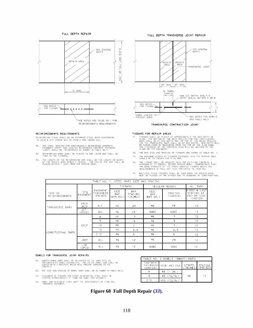
118
Figure 68 Full Depth Repair (33).
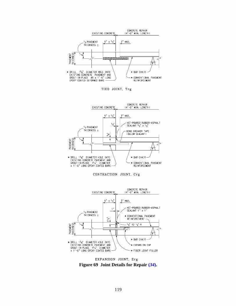
119
Figure 69 Joint Details for Repair (34).
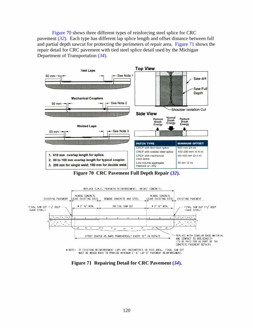
120
Figure 70 shows three different types of reinforcing steel splice for CRC pavement (32). Each type has different lap splice length and offset distance between full and partial depth sawcut for protecting the perimeters of repair area. Figure 71 shows the repair detail for CRC pavement with tied steel splice detail used by the Michigan Department of Transportation (34).
Figure 70 CRC Pavement Full Depth Repair (32).
Figure 71 Repairing Detail for CRC Pavement (34).
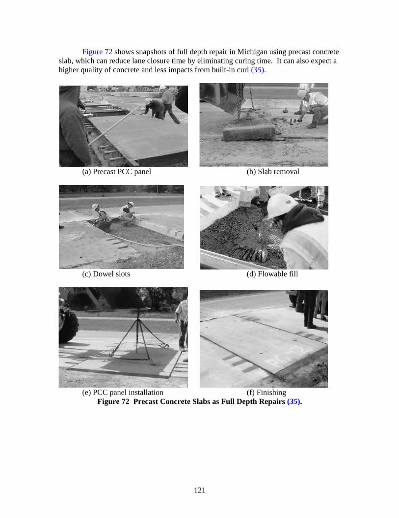
121
Figure 72 shows snapshots of full depth repair in Michigan using precast concrete slab, which can reduce lane closure time by eliminating curing time. It can also expect a higher quality of concrete and less impacts from built-in curl (35).
(a) Precast PCC panel (b) Slab removal
(c) Dowel slots (d) Flowable fill
(e) PCC panel installation (f) Finishing
Figure 72 Precast Concrete Slabs as Full Depth Repairs (35).
122
Description This Item shall govern for full depth repair of existing sections of Portland cement
concrete pavement in accordance with the existing roadway section and the details shown on the plans, and to the lines and grades established by the engineer. The following special specification is referred from TxDOT (36). Materials
Provide materials that meet the pertinent requirements of the following: • Item 360, “Concrete Pavement”; • Item 421, “Hydraulic Cement Concrete”; • Item 440, “Reinforcing Steel”; and • DMS 6100, “Epoxies and Adhesives.”
A. Hydraulic Cement Concrete for Pavement
If the time frame designated for opening to traffic is less than 72 hours after concrete placement, provide Class HES concrete designed to attain a minimum average flexural strength of 255 psi or a minimum average compressive strength of 1,800 psi within the designated time frame. Otherwise provide Class P concrete conforming to Item 360, “Concrete Pavement.” Type III cement is permitted for Class HES concrete. B. Base Material
Unless otherwise shown on the plans or permitted, furnish pavement concrete for replacement base material when required. The engineer may waive quality control tests for base material. C. Asphalt Concrete
Furnish asphalt concrete material for overlay and asphalt shoulder repair in accordance with Item 340, “Dense-Graded Hot-Mix Asphalt (Method),” as shown on the plans. The engineer may waive quality control tests for this material. Construction Method
Repair areas identified by the engineer. Make repair areas rectangular, at least 6 ft
long and at least 1/2 a full lane in width unless otherwise shown on the plans. Unless otherwise shown on the plans, accept ownership of all removed material, and dispose of it in accordance with federal, state, and local regulations. Sawcut and remove existing asphalt concrete overlay over the repair area and at least 6 in. outside each end of the repair area. Sawcut full depth through the concrete around the perimeter of the repair area before removal. Do not spall or fracture concrete adjacent to the repair area. Schedule work so that concrete placement follows full depth sawcutting by no more than 7 days unless otherwise shown on the plans or approved.
123
Remove or repair loose or damaged base material, and replace or repair it with approved base material to the original top of the base grade. Place a polyethylene sheet at least 4 mils thick as a bond breaker at the interface of the base and new pavement. Allow concrete used as base material to attain sufficient strength to prevent displacement when placing pavement concrete.
Use only drilling operations that do not damage the surrounding operations. Place new deformed reinforcing steel bars of the same size and spacing as the bars removed or as shown on the plans. Lap all reinforcing steel splices in accordance with Item 440, “Reinforcing Steel.” Place dowel bars and tiebars as shown on the plans. Epoxy-grout all tiebars for at least a 12 in. embedment into existing concrete. Completely fill the tiebar hole with Type III, Class A or Class C epoxy before inserting the tiebar into the hole. Provide grout retention disks for all tiebar holes. Provide and place approved supports to firmly hold the new reinforcing steel, tiebars, and dowel bars in place. Demonstrate, through simulated job conditions, that the bond strength of the epoxy-grouted tiebars meets a pullout strength of at least 3/4 of the yield strength of the tiebar when tested in accordance with ASTM E 488 within 18 hours after grouting. Increase embedment depth and retest when necessary to meet testing requirements. Perform tiebar testing before starting repair work.
Mix, place, cure, and test concrete to the requirements of Item 360, “Concrete Pavement,” and Item 421, “Hydraulic Cement Concrete.” Broom-finish the concrete surface unless otherwise shown on the plans. Match the grade and alignment of existing concrete pavement. After concrete strength requirements have been met, replace any asphalt overlay and shoulder material removed with new asphalt concrete material in accordance with Item 340, “Dense-Graded Hot-Mix Asphalt (Method).”
For repair areas to be opened to traffic before 72 hours, use curing mats to maintain a minimum concrete surface temperature of 70 °F when air temperature is less than 70 °F. Cure the repaired area for at least 72 hours or until overlaid with asphalt concrete, if required, or until the area is opened to traffic. Saw and seal contraction joints in the repair area in accordance with Item 360, “Concrete Pavement.” Remove repair area debris from the right of way each day.
Measurement
This Item will be measured by the square yard of concrete surface area repaired.
No measurement will be made for areas damaged because of contractor negligence. Payment
The work performed and the materials furnished in accordance with this Item and
measured as specified under “Measurement” will be paid for at the unit price bid for “Full Depth Repair” of the type and depth specified. This price is full compensation for removal, stockpiling, and disposal of waste material and for equipment, materials, labor, tools, and incidentals. Asphalt concrete, base material, and curbing will not be paid for directly but will be considered subsidiary to this Item.


125
CHAPTER 7 CONCLUSIONS
This report discusses the identification of various distress types by visual survey
and introduces recommendable evaluation techniques, which is key to determining proper routine maintenance activities.
There are many well-organized visual pavement condition survey protocols used by highway agencies to monitor and record pavement distresses. However, current survey protocols often require a level of inspection detail greater than what is normally needed for a routine maintenance survey; therefore, simplified survey tables have been provided.
Based on the areas selected from the checklist of visual survey, deflection testing using FWD can evaluate the structural condition of pavement such as layer stiffness, LTE, and loss of support below the slab. GPR testing determines base conditions such as voids and the presence of water trapped in and between underlying pavement layers. Moreover, GPR survey can be used for PCC pavement layer thickness estimation, layer interface condition assessment, and dowel misalignment evaluation. DCP testing indicates the in situ strength of base and subgrade soils. It is a fast and easy method and can be used to estimate the effective stiffness and thickness of the concrete layer, particularly at joints and cracks.
Based on distress type and pavement condition evaluation information, the following are recommended for the decision process of routine maintenance:
• If pavement age is more than 10 years for PCC or 2 years for AC overlaid pavement, the pavement condition survey should be updated.
• Based on visual survey results, distressed areas may need further testing using NDT and other techniques to evaluate the structural condition.
• Crack sealing is recommended when crack width is wider than 0.03 in. • Resealing joints and cracks is recommended when sealants are damaged over more
than 20 percent along the joint or crack. • If depressed areas are present, transverse grade re-profiling should be employed to
provide drainage of the surface. • If geometry and circumstances facilitate drainage, a retrofit edge drain is
recommended when water under the slab is identified or when the DC value is higher than 9 and the subgrade PR is smaller than 2 in. per blow.
• Edge drainage is not recommended if the base is unstabilized and the base contains more than 15 percent fines (passing No. 200 sieve) or the pavement structure is undrainable.
• When 2 in. wide spalls are more than 10 percent of a crack or joint, partial depth repair should be employed using proper patching materials for PCC pavement and AC overlaid PCC pavement.
• The depth of spall should be less than 1/3 the thickness of the slab, and the pavement should have no reinforcing steel exposure.
• Partial depth repair also can be applied for deep delamination up to half of the CRC pavement thickness if the remaining slab is strong with no other distress and the steel is not corroded.
126
• Partial depth repairs should restore the joint face, and the joint should be sealed properly.
• When patches are more than 10 per mile and faulting is more than 1/4 in., diamond grinding can provide a smooth riding surface with good texture and noise reduction.
• When stabilized bumps or settled areas are present, diamond grinding can also be effective.
• Grinding should not be employed on pavements with material problems or if the aggregate type is too hard to grind economically. Employing AC overlay for hard aggregate pavements is perhaps a good alternative instead of diamond grinding.
• A thin AC overlay with petromat can be used to restore the functional capacity of a pavement and improve rideability. Existing structural distresses must be repaired and restored before the overlay is placed. This is important particularly if the pavement is structurally deficient to avoid premature failure. Use of a crack attenuating mix with good aggregate is recommended to minimize reflection cracking.
• When LTE is lower than 70 percent, the basin area is less than 25 in., and joints are spalled more than 2 in. wide over more than 20 percent, then restoration of road transfer is recommended to address faulting, pumping, and crack or joint deterioration.
• Before and after restoring road transfer, slab stabilization may be needed to address loss of support and diamond grinding needed to remove existing faulting.
• Pavements exhibiting material-related distresses such as D-cracking or reactive aggregate are not candidates for dowel bar retrofitting.
• Cross stitching holds a longitudinal crack or joint together and prevents opening and closing over time. Cross stitching is recommended when longitudinal cracks or shoulder joints separate wider than 1/2 in.
• In the case of shoulder joint separation, cross stitching and joint sealing are recommended when shoulder joint separation is between 1/2 in. and 1 in. in width. In order for joint sealing to be effective, the shoulder joint separation should remain smaller than 1/2 in.
• Slab undersealing is recommended when GPR-indicated voided cracks or joints are more than 20 percent of the inspected section or where unstable bumps or unstable settlement is present.
• Experienced contractors and proper inspection are essential to properly identify and underseal damaged areas. Therefore, GPR is recommended to locate holes in a way that will ensure good grout distribution and void filling.
• Full depth repair can be considered when corner breaks are more than 10 percent or the slab is shattered in JC pavement and when punchouts are more than 10 percent in CRC pavement.
• Soft subgrade materials may require removal and full depth repair, particularly in areas where cluster cracking is present. Grinding may be used to improve roughness created by placement of the FDR. If the deterioration is widespread over the entire project length, an overlay or reconstruction may be more cost-effective.
127
In the field tests, the problems in poorly performing areas were identified, and possible improvements by proper repair methods and guidelines are provided. Nondestructive testing and coring were used to evaluate the effectiveness of FDR sections and current JC pavement condition on US 75 near Sherman, Texas. Overall FDR effectiveness was low. The drainage conditions were generally poor, and standing water existed alongside the pavement shoulder joint. Since LTE and subgrade moduli of FDR were low, improved FDR design may entail base and subgrade replacement, subdrain system, diamond grinding, and joint sealing to improve performance, while existing patches should be checked by NDT and properly maintained through restoring load transfer to prolong the service life.
US 59 in the Lufkin, Diboll, and Leggett area was tested using RDD and GPR testing. All test sections consisted of an ACOL on PCC and showed good performance with no reflection crack from the underlying PCC joints. Joint locations were not detectable visually, and the surface condition was good. Because layer profile, subgrade, base, drainage condition, and service life are not the same, it is inconclusive as to how cost-effective these types of repairs are for joint deterioration. Fiber screed appears to increase the structural capacity of the joint, however. The overall drainage condition along the shoulder joint should be checked, and proper edge drainage can help to reduce moisture damage in the subbase or subgrade layer.
Since the overlay age is more than 2 years old and some sections have voids and wet areas, careful monitoring should be routinely employed to ensure pavement life by preventing abrupt change in performance. When reflection cracking becomes evident, crack sealing should be applied to prevent surface water intrusion, which degrades pavement over time. If joint faulting develops, milling the overlay and retrofit load transfer are recommended to preserve pavement integrity. In the future, if pumping evidence is detected, particularly at the joint location, edge drainage should be considered to reduce moisture damage of the subbase or subgrade.
US 287 northbound JC pavement sections near Vernon, Texas, were tested using FWD, DCP, and coring. The significant difference between good and poor performing sections was joint sealing condition. Crack and joint sealing in the poor condition section was damaged in many areas, and the shoulder joint was wide. The different aggregate type may be a factor in joint sealing problems. The aggregate type of the good condition area is limestone, and that of the poor condition area is gravel. FWD data show no difference between good and poor condition sections, but the LTE and basin areas are low, possibly requiring retrofit load transfer. DCP test results show how good joint sealing can effectively prevent pumping and erosion damage since the good condition area has low base and subgrade erosion and well-maintained joint sealing.
Dowel bar retrofitting with diamond grinding and joint/crack resealing was employed to address faulting in the Quanah sample sections. The repaired sections showed high LTE and no distress in spite of a weak and wet subgrade condition. Due to the thickness of the existing concrete slab and base layer, erosion near the joint may be minimized over time. Therefore, slab undersealing and edge drainage may be needed to fill voids under the slab and reduce further moisture damage on the base and subgrade.

129
REFERENCES
1. Scullion, T., M. Coppock, and C. Von Holdt. “Development of a Concrete Pavement Rehabilitation Training CD-ROM,” Texas Department of Transportation, Austin, Texas, August 2006.
2. “Pavement Management Information System Rater’s Manual for Fiscal Year 2008,” Texas Department of Transportation, Austin, Texas, June 2007.
3. “Distress Identification Manual for the Long-Term Pavement Performance Project,” SHRP-P-338, Strategic Highway Research Program, National Research Council, Washington, D.C., 1993.
4. Zollinger, D. G., S.D. Tayabji, and K.D. Smith. “Repair and Rehabilitation of Concrete Pavements, Volume II: Guidelines for Pavement Condition Assessment and Evaluation,” Report FHWA-RD-03-R-00XYZ, FHWA, U.S. Department of Transportation, Washington, D.C., 2003.
5. Huang, Y.H. “Pavement Analysis and Design, 2nd Edition,” Pearson Prentice Hall, Upper Saddle River, New Jersey, 2004.
6. Lee, J. L., and K. H. Stokoe. “Improved Testing Speed of the Rolling Dynamic Deflectometer: A Summary,” Project Summary Report 0-4357-S, Center for Transportation Research, Austin, Texas, 2005.
7. Hoerner, T., K.D. Smith, H.T. Yu, D.G. Peshkin, and M.J. Wade. “PCC Pavement Evaluation and Rehabilitation,” Reference Manual, NHI Course 131062, National Highway Institute, Arlington, Virginia, 2001.
8. “Joint and Crack Sealing and Repair for Concrete Pavements,” TB012P, American Concrete Pavement Association, Skokie, Illinois, 1995.
9. “Resealing Joints in PCC Concrete Pavement and Bridge Deck Patching PCC Concrete Pavement,” Construction Details P-3, Georgia Department of Transportation, Atlanta, Georgia, September 1998.
10. “Concrete Pavement — Joint Details,” 2006 Standard Plan P20, California Department of Transportation, Sacramento, California, May 2006.
11. “Specification Section 461 — Sealing Roadway and Bridge Joints and Cracks,” Georgia Department of Transportation, http://tomcat2.dot.state.ga.us/ thesource/specs/index.html, revised: 2001, accessed: February 20, 2008.
12. “Concrete Pavement Repair Manual,” JP0002P, American Concrete Pavement Association, Skokie, Illinois, 2003.
130
13. “Underdrain and Outlets Pavement Edge Drain,” Standard Plan, Connecticut Department of Transportation, Newington, Connecticut, August 1991.
14. “Full Depth PCC Patch with Dowels (Existing Non-composite Pavement),” Standard Road Plan: Pavements Rehabilitation RR-4, Iowa Department of Transportation, Ames, Iowa, 2007.
15. “2006 Standard Specification 605.2410 17 — Prefabricated Geocomposite Edge Drain,” New York State Department of Transportation, https://www.nysdot.gov/ portal/page/portal/main/business-center/engineering/specifications/2006-standard-specs, revised: September 2006, accessed: February 20, 2008.
16. “Concrete Crack and Partial-Depth Spall Repair Manual,” JP003P, American Concrete Pavement Association, Skokie, Illinois, 2004.
17. “Guidelines for Partial-Depth Spall Repair,” TB003P, American Concrete Pavement Association, Skokie, Illinois, 1998.
18. “Transverse Joint Repair Detail,” Plans of Proposed State Highway Improvement, Project No. C176-5-145, Lufkin District, Texas Department of Transportation, Lufkin, Texas, April 2003.
19. Won, M. “Alternative Repair Strategy to Full Depth Repair for Deep Delamination,” Technical Conversation, Center for Transportation Research, Austin, Texas, February 2008.
20. “Specification Section 451 — Patching Portland Cement Concrete Pavement (Spall Repair),” Georgia Department of Transportation, http://tomcat2.dot.state.ga.us/ thesource/specs/index.html, revised: 2001, accessed: February 20, 2008.
21. “Diamond Grinding and Concrete Pavement Restoration,” TB008P, American Concrete Pavement Association, Skokie, Illinois, 2000.
22. “2004 English Special Specifications for Atlanta 3014 Diamond Grinding Concrete Pavement,” Texas Department of Transportation, ftp://ftp.dot.state.tx.us/pub/txdot-info/cmd/cserve/specs/2004/spec/ss3014.pdf, revised: 2004, accessed: February 20, 2008.
23. “Concrete Pavement Rehabilitation: Guide for Load Transfer Restoration,” JP0001P, American Concrete Pavement Association, Skokie, Illinois, 1998.
24. “Specification Guideline for Dowel Bar Retrofit,” IS104P, American Concrete Pavement Association, Skokie, Illinois, 2002.
25. “Dowel Bar Retrofit (Existing Jointed Plain Concrete Pavement),” 2006 Standard Plan P7, California Department of Transportation, Sacramento, California, May 2006.
131
26. “Dowel Bar Retrofit for Cement Concrete Pavement,” Standard Plan A-5, Washington State Department of Transportation, Olympia, Washington, February 2003.
27. “Special Provision for Dowel Bar Retrofit for Load Transfer across Cracks in PCC Pavement,” Michigan Department of Transportation, http://mdotwas1.mdot.state.mi.us/public/dessssp/spss/index.cfm, revised: February 2000, accessed: February 20, 2008.
28. “Stitching Concrete Pavement Cracks and Joints,” SR903P, American Concrete Pavement Association, Skokie, Illinois, 2001.
29. “2000 Standard Specifications for Roads and Bridges Manual, 602.15 Cross-Stitching Random Longitudinal Cracks,” Louisiana Department of Transportation, http://www.dotd.louisiana.gov/highways/project_devel/contractspecs/Part_VI.pdf, revised: 2000, accessed: February 20, 2008.
30. “Slab Stabilization Guidelines for Concrete Pavements,” TB018P, American Concrete Pavement Association, Skokie, Illinois, 1994.
31. “Special Specification 3043 Raising and Undersealing Concrete Slabs,” Texas Department of Transportation, ftp://ftp.dot.state.tx.us/pub/txdot-info/cmd/cserve/specs/2004/spec/ss3043.pdf, revised: April 2005, accessed: February 20, 2008.
32. “Guidelines for Full-Depth Repair,” TB002P, American Concrete Pavement Association, Skokie, Illinois, 1995.
33. “Full Depth Repair for Concrete Pavement,” Roadway Standards: Pavements FDRCP-05, Texas Department of Transportation, Austin, Texas, September 1994.
34. “Concrete Pavement Repair,” Standard Road Plans R-44-E, Michigan Department of Transportation, Lansing, Michigan, October 2004.
35. Buch, N., V. Barnhart, and R. Kowli. “Precast Concrete Slabs as Full-Depth Repairs: Michigan Experience,” Transportation Research Record 1823, Journal of the Transportation Research Board, Washington, D.C., 2003, pp. 55-63.
36. “Standard Specifications for Construction and Maintenance of Highways, Streets, and Bridges, Item 361 Full-Depth Repair of Concrete Pavement,” Texas Department of Transportation, ftp://ftp.dot.state.tx.us/pub/txdot-info/des/specs/specbook.pdf, revised: June 2004, accessed: February 20, 2008.