Embed Size (px)
Citation preview

Technical Report Documentation Page 1. Report No. FHWA/TX-12/0-6729-1
2. Government Accession No.
3. Recipient's Catalog No.
4. Title and Subtitle SYNTHESIS ON COST-EFFECTIVENESS OF EXTRADOSED BRIDGES: TECHNICAL REPORT
5. Report Date October 2012 Published: March 2016 6. Performing Organization Code
7. Author(s) Jiong Hu, Yoo Jae Kim, and Soon-Jae Lee
8. Performing Organization Report No. Report 0-6729-1
9. Performing Organization Name and Address Texas State University–San Marcos The Texas State University System San Marcos, Texas 78666-4684
10. Work Unit No. (TRAIS) 11. Contract or Grant No. Project 0-6729
12. Sponsoring Agency Name and Address Texas Department of Transportation Research and Technology Implementation Office P.O. Box 5080 Austin, Texas 78763-5080
13. Type of Report and Period Covered Technical Report: September 2011–August 2012 14. Sponsoring Agency Code
15. Supplementary Notes Project performed in cooperation with the Texas Department of Transportation and the Federal Highway Administration. Project Title: Synthesis on Cost-Effectiveness of Extradosed Bridges URL: http://tti.tamu.edu/documents/0-6729-1.pdf 16. Abstract An extradosed bridge is a unique bridge type that utilizes both prestressed girder bridge and cable-stayed bridge concepts. Since the concept of an extradosed bridge is still relatively new, there is no clear definition and specification of the type of bridge. Also, due to the unique characteristics of an extradosed bridge, it is likely to initially cost more than a conventional girder bridge but less expensive compared to a cable-stayed bridge. This synthesis study identified and collected information on 120 extradosed bridges from Asia, Europe, North America, South America and Africa through a comprehensive literature review of over 350 technical papers, reports, and websites. Cost information on 58 extradosed bridges and bridge selection reasons for 47 extradosed bridges were collected and summarized. Over 100 individuals with experience in the design and/or construction of extradosed bridges were contacted. Telephone and emailinterviews of eight experts in extradosed bridges (three from Asia, three from Europe, and two from North America) were conducted. A statistical analysis was conducted to summarize general configurations, bridge selections, constructions, and costs of extradosed bridges. Four case studies regarding extradosed bridge selection were also included in the report. In addition, this study summarized the advantages and disadvantages of utilizing extradosed bridges, best practices, and existing methodologies. While there is a variety of advantages and disadvantages comparing extradosed bridges to girder bridges and cable-stayed bridges, the team identified aesthetic (signature bridge and landmark structure), underneath (navigation/vehicular) clearance and higher restriction, and construction and structure considerations were identified as top reasons for selecting extradosed bridges over other alternatives. A bridge selection process specifying considerations for determining how and when an extradosed bridge is cost-effective and in the best interest of the public was also recommended. 17. Key Words Extradosed, Cable-Stayed, Girder, Cost-Effectiveness, Bridge Selection
18. Distribution Statement No restrictions. This document is available to the public through NTIS: National Technical Information Service Alexandria, Virginia 22312 http://www.ntis.gov
19. Security Classif. (of this report) Unclassified
20. Security Classif. (of this page) Unclassified
21. No. of Pages 192
22. Price
Form DOT F 1700.7 (8-72) Reproduction of completed page authorized


SYNTHESIS ON COST-EFFECTIVENESS OF EXTRADOSED BRIDGES: TECHNICAL REPORT
by
Jiong Hu, Ph.D. Assistant Professor
Texas State University–San Marcos
Yoo Jae Kim, Ph.D. Assistant Professor
Texas State University–San Marcos
and
Soon-Jae Lee, Ph.D. Assistant Professor
Texas State University–San Marcos
Report 0-6729-1 Project 0-6729
Project Title: Synthesis on Cost-Effectiveness of Extradosed Bridges
Performed in cooperation with the Texas Department of Transportation
and the Federal Highway Administration
October 2012 Published: March 2016
TEXAS STATE UNIVERSITY-SAN MARCOS The Texas State University System
San Marcos, Texas 78666-4684

v
DISCLAIMER
This research was performed in cooperation with the Texas Department of Transportation
(TxDOT) and the Federal Highway Administration (FHWA). The contents of this report reflect
the views of the authors, who are responsible for the facts and the accuracy of the data presented
herein. The contents do not necessarily reflect the official view or policies of the FHWA or
TxDOT. This report does not constitute a standard, specification, or regulation. The researcher in
charge of the project was Jiong Hu.
vi
ACKNOWLEDGMENTS
This project was conducted in cooperation with the Texas Department of Transportation
(TxDOT) and the Federal Highway Administration (FHWA). The authors express their
appreciation to TxDOT personnel for their support throughout this study. Special thanks are
extended to Nicholas Nemec as the project director (PD), Wade Odell as Research Engineer,
Project Monitoring Committee (PMC) members Alanna Bettis, Brian Merrill, Dean Van
Landuyt, Gregg Freeby, Paul Cepak, and Sandra Kaderka as contract specialist. Akio Kasuga
(Sumitomo Mitsui Construction), Christopher Scollard (Buckland & Taylor Ltd.), Steven L.
Stroh (URS Corporation), Jiri Strasky (Strasky, Husty and Partners, Ltd.), Deong-Hwan Park
(DongMyeong Engineering Consultants Co. LTD), Sun-Joo Choi (Yooshin Engineering Corp),
Viktor Markelj (PONTING d.o.o. Maribor), and Aivar-Oskar Saar (Järelpinge Inseneribüroo
OÜ) for their input regarding extradosed bridges and help during data collection and interviews.
The authors also thank research assistants Zhuo Wang, Ashley Kotwel, Michael Grams, and
Chase David for their assistance in this study.

vii
TABLE OF CONTENTS
Page List of Figures ............................................................................................................................... ix List of Tables ................................................................................................................................ xi Chapter 1. Introduction................................................................................................................ 1
Research Background ................................................................................................................. 1 Research Objectives .................................................................................................................... 2 Research Approaches .................................................................................................................. 2
Literature Review................................................................................................................ 2 Interviews ............................................................................................................................ 2 Case Studies ........................................................................................................................ 4
Scope of Research and Organization of the Report .................................................................... 4 Chapter 2. General Aspects of Extradosed Bridges .................................................................. 7
History of Extradosed Bridges .................................................................................................... 7 Configuration and Definitions of Extradosed Bridges.............................................................. 11 Extradosed Bridge Construction ............................................................................................... 13 Extradosed Bridge Maintenance ............................................................................................... 15 Summary ................................................................................................................................... 16
Chapter 3. Review of Extradosed Bridges ................................................................................ 17 General Information of Extradosed Bridges ............................................................................. 17 Locations and Construction Time of Extradosed Bridges ........................................................ 26 Purposes and Usage of Extradosed Bridges .............................................................................. 29 Configurations of Extradosed Bridges ...................................................................................... 30 Summary ................................................................................................................................... 45
Chapter 4. Cost of Extradosed Bridges Construction ............................................................. 47 Cost Analysis through General Surveys ................................................................................... 47
Cost Comparsion through Specific Resources .................................................................. 58 Summary ................................................................................................................................... 63
Chapter 5. Bridge Selection Procedures and Considerations ................................................. 65 Commonly Used Bridge Selection Procedures and Considerations ......................................... 65
Life Cycle Cost Analysis (LCCA) .................................................................................... 66 Value Engineering (VE) and Criteria-Based Bridge Selection Procedures ...................... 69
Advantages and Disadvantages of Extradosed Bridges ............................................................ 72 Major Reasons for Selecting Extradosed Bridges .................................................................... 74
Aesthetics Considerations ................................................................................................. 77 Economic Considerations ................................................................................................. 78 Height Restriction and Clearance ..................................................................................... 78 Compatibility and Environmental Considerations ............................................................ 80 Construction and Structure Considerations ...................................................................... 82
Statistics of Bridge Selection Reasons ...................................................................................... 86 Case Studies for Bridge Selection ............................................................................................. 88
Case #1 Sunniberg Bridge ................................................................................................ 89 Case #2 Zhangzhou Zhanbei Bridge ................................................................................. 92 Case #3 St. Croix River Crossing ..................................................................................... 96 Case #4 Walterdale River Bridge Replacement ................................................................ 99

viii
Recommended Bridge Selection Procedure and Considerations ............................................ 106 Summary ................................................................................................................................. 109
Chapter 6. Conclusions and Recommendations ..................................................................... 111 Conclusions ............................................................................................................................. 111 Recommendations ................................................................................................................... 113 References ............................................................................................................................... 115
Appendix A: List of References for Each Extradosed Bridges............................................. 135 Appendix B: Summary of Extradosed Bridges ...................................................................... 141 Appendix C: Interview Questions and Records ..................................................................... 167

ix
LIST OF FIGURES
Page Figure 1. “Extradosed” Concept at Arrêt-Darré Viaduct (picture adapted from Virlogeux 1999). 7 Figure 2. Finback Bridge–Barton Creek Bridge (photo from the Authors). ................................... 8 Figure 3. Cable-Panel Bridge–Ganter Bridge (photo adapted from lookbridges.com 2012). ........ 9 Figure 4. Typical Layouts of Finback, Cable-Panel and Extradosed Bridges. ............................. 10 Figure 5. First Extradosed Bridge–Odawara Blueway Bridge. .................................................... 11 Figure 6. Construction of Extradosed Bridge (adapted from vsl.cz 2012). .................................. 13 Figure 7. Major Extradosed Bridge Erection Sequence (adapted from Stroh 2012) .................... 14 Figure 8. Example of Free Balanced Cantilever Method for Extradosed Bridge Construction
(Ritto Bridge) (adapted from tripod.com 2012). ................................................................... 15 Figure 9. Distribution of Extradosed Bridges (by Continents). .................................................... 26 Figure 10. Distribution of Extradosed Bridges (by Countries). .................................................... 27 Figure 11. Distribution of Extradosed Bridges (by Completion Year). ........................................ 28 Figure 12. Distribution of Construction Duration......................................................................... 28 Figure 13. Extradosed Bridges Serving Different Purposes. ........................................................ 29 Figure 14. Distributions of Bridge Purposes................................................................................. 30 Figure 15. Distribution of Quantities of Spans. ............................................................................ 31 Figure 16. Examples of Bridges with the Highest and Lowest Number of Spans........................ 31 Figure 17. Distribution of Number of Towers. ............................................................................. 32 Figure 18. Examples of Extradosed Bridges with Different Numbers of Towers. ....................... 32 Figure 19. Distributions of Maximum Span Lengths. .................................................................. 33 Figure 20. Distribution of Total Span Length. .............................................................................. 33 Figure 21. Extradosed Bridges with Longest and Shortest Main and Total Span Lengths. ......... 34 Figure 22. Distribution of Tower Height. ..................................................................................... 34 Figure 23. Extradosed Bridges with the Tallest and Shortest Towers. ......................................... 35 Figure 24. Distribution of Main Span-Height Ratio. .................................................................... 36 Figure 25. Extradosed Bridges with Highest and Lowest Span-Tower Height Ratios. ................ 36 Figure 26. Examples of Extradosed Bridges with Constant and Variable Girder Thickness. ...... 37 Figure 27. Distribution of Girder Thickness (Constant or Variable). ........................................... 37 Figure 28. Distribution of Superstructure Materials. .................................................................... 38 Figure 29. Examples of Extradosed Bridges with Different Superstructure Materials. ............... 39 Figure 30. Examples of Girder with Different Numbers of Cells in Box Girders. ....................... 40 Figure 31. Distribution of Number of Cells. ................................................................................. 40 Figure 32. Distribution of Girder Depth at Midspan. ................................................................... 41 Figure 33. Distribution of Girder Depth at Tower. ....................................................................... 41 Figure 34. Examples of Bridges with Different Girder Thicknesses. ........................................... 42 Figure 35. Distribution of Span/Depth Ratio (Midspan). ............................................................. 43 Figure 36. Distribution of Span/Depth Ratio (Tower). ................................................................. 43 Figure 37. Distribution of Girder Width. ...................................................................................... 44 Figure 38. Distribution of Total Construction Cost. ..................................................................... 51 Figure 39. Distribution of Superstructure Cost. ............................................................................ 52 Figure 40. Distribution of Substructure Cost. ............................................................................... 53 Figure 41. Distribution of Superstructure Cost %. ....................................................................... 54
x
Figure 42. Distribution of Unit Cost. ............................................................................................ 56 Figure 43. Distribution of Unit Cost of Superstructure. ............................................................... 57 Figure 44. Cost Index of Different Types of Bridges from Sumitomo Mitsui Construction. ....... 62 Figure 45. Span Ranges for Different Types of Bridges. ............................................................. 66 Figure 46. BLCCA Process (adapted from Hawk 2003). ............................................................. 68 Figure 47. Examples of Bridges Selected for Aesthetic Reasons. ................................................ 77 Figure 48. Example of Consideration of Aviation Restriction (North Arm Bridge). ................... 78 Figure 49. Example of Height Restriction to Fit Adjacent Structures (Second Vivekananda
Bridge). ................................................................................................................................. 79 Figure 50. Example of Bridge with Navigation Clearance Requirement (Odawara Bridge) ....... 80 Figure 51. Example of Bridge with Vehicular Clearance Requirement (Pont de Saint-Rémy-de-
Maurienne Bridge). ............................................................................................................... 80 Figure 52. Examples of Bridges Selected due to Less Environmental Impact (Ailan Bridge). ... 81 Figure 53. Example of Bridge with Low Visual Impact (Sunniberg Bridge). .............................. 81 Figure 54. Example of Bridge with Span at Deep Valley (Trois-Bassins Viaduct). .................... 82 Figure 55. Example of Bridge with Least Navigation Interference in Flood Zone (Liuzhou
Sanmenjiang Bridge). ........................................................................................................... 83 Figure 56. Example of Bridge with Proper Span for Curvature (Puh Bridge). ............................ 83 Figure 57. Examples of Bridge in Unique Site Conditions. ......................................................... 84 Figure 58. Example of Bridge with Construction Consideration (New Pearl Harbor Memorial
Bridge). ................................................................................................................................. 85 Figure 59. Example of Bridge with Structure Consideration (Golden Ears Bridge). ................... 86 Figure 60. Statistics of Considerations in Selecting Extradosed Bridges. .................................... 87 Figure 61. Summary of Bridge Selection Reasons. ...................................................................... 88 Figure 62. Alternative Designs of the Sunniberg Bridge (adapted from Drinkwater 2012). ........ 90 Figure 63. Final Design of Sunniberg Bridge with Extradosed Concept (adapted from Drinkwater
2012). .................................................................................................................................... 91 Figure 64. Sunniberg Bridge (Wilhelm Ernst & Sohn 2012). ...................................................... 92 Figure 65. Alternative Designs for Zhangzhou Zhanbei Bridge................................................... 93 Figure 66. Zhangzhou Zhanbei Bridge (adapted from China.com 2012). .................................... 96 Figure 67. Stillwater Lift Bridge. .................................................................................................. 97 Figure 68. Selected “Build” Alternatives for St. Croix River Crossing Project Selection. .......... 98 Figure 69. Existing Walterdale Bridge ....................................................................................... 100 Figure 70. Alternatives of Walterdale Bridge Replacement. ...................................................... 102 Figure 71. Recommended Bridge Selection Process Flowchart. ................................................ 108

xi
LIST OF TABLES
Page Table 1. Information of Interviewees. ............................................................................................. 3 Table 2. Comparison of Girder, Extradosed, and Cable-Stayed Bridges. .................................... 12 Table 3. General Information of Extradosed Bridges. .................................................................. 18 Table 4. Summary of Configurations of Extradosed Bridges. ...................................................... 22 Table 5. Statistics of Configurations of Extradosed Bridges. ....................................................... 44 Table 6. General Statistics of Configuration of Extradosed Bridges. ........................................... 45 Table 7. Historical Costs of Extradosed Bridges. ......................................................................... 48 Table 8. Historical Costs of Superstructure and Substructure of Extradosed Bridges. ................ 50 Table 9. Statistics of Extradosed Bridge Construction Costs. ...................................................... 58 Table 10. Unit Costs based on Types of Bridges (data obtained from Company A). .................. 60 Table 11. Cost Index of Different Extradosed Bridges (data obtained from Sumitomo Mitsui
Construction)......................................................................................................................... 61 Table 12. Prototype of Bridge Selection Matrix Based on LCCA with Dummy Data. ................ 68 Table 13. Example of Analysis Matrix using VE Method ( from Basha and Gab-Allah 1991). .. 71 Table 14. Example of Criteria-Based Bridge Selection Matrix. ................................................... 72 Table 15. Example of Criteria-Based Bridge Selection Scoring System with Dummy Data. ...... 72 Table 16. Advantages and Disadvantages of Extradosed Bridges. ............................................... 73 Table 17. Extradosed Bridge Selection Reasons. ......................................................................... 75 Table 18. List of Cases Included in the Case Studies. .................................................................. 89 Table 19. Configuration Comparisons of Different Bridges. ....................................................... 94 Table 20. Materials Consumption Comparisons of Different Bridges. ........................................ 95 Table 21. Comparison of Different Alternatives of Walterdale Bridge Replacement. ............... 104 Table 22. Capital Costs of Different Alternatives in Walterdale Bridge Replacement. ............. 105 Table 23. Life Cycle Costs of Different Alternatives in Walterdale Bridge Replacement. ........ 105 Table 24. Recommended Bridge Selection Preferences under Different Considerations. ......... 106

1
CHAPTER 1. INTRODUCTION
RESEARCH BACKGROUND
An extradosed bridge is a relatively new type of bridge that provides a cross between
prestressed girder bridges and cable-stayed bridges. Generally speaking, the extradosed bridge
has the appearance of a cable-stayed bridge with shorter towers; however, the bridge behaves
structurally closer to a prestressed girder bridge with external prestressing. In an extradosed
bridge, the main girder is directly supported by resting on part of the towers. Therefore, in close
proximity to the towers, the girder in an extradosed bridge can act as a continuous beam. Cables
from lower towers in an extradosed bridge intersect with the girder only further out, and at a
lower angle. With this reason, in an extradosed bridge, tension forces in the girder act more to
compress the bridge girder horizontally, rather than support it vertically; thus, the cables act as
prestressing cables for a concrete girder. The girder in an extradosed bridge can be thinner than
that of a girder bridge of a comparable span, but thicker than that of a conventional cable-stayed
bridge. Since the first extradosed bridge built in Japan in 1994, there has been a steady increase
of this type of bridge, especially in Asia. However, in most other countries, this typology still
remains unfamiliar to many engineers; the cost-effectiveness of the bridge and when this type of
bridge should be considered or selected is still not clear.
Given the intermediate design of an extradosed bridge, it is unsurprising that this type of
bridge is relatively expensive (compared to a girder bridge) and material inefficient (compared to a
cable-stayed bridge). A synthesis study examines basic configurations; overall cost-effectiveness,
together with selection processes and considerations of the extradosed bridge, is therefore needed.
This study summarizes the advantages and disadvantages of utilizing extradosed bridges, and the
methods for cost-effectiveness analyses and bridge selection procedures through a comprehensive
literature review. Surveys and interviews were conducted to obtain additional information and
insights concerning selecting an extradosed bridge. While there is no standard method/procedure in
bridge selection, the feasibility of applying methods including Life Cycle Cost Analysis (LCCA),
Value Engineering (VE) analysis, criteria-based bridge selection approaches in cost-effectiveness
analyses and bridge selections will be evaluated. This synthesis study summarizes the best
practices and existing methodologies in determining how and when an extradosed bridge is cost-
2
effective. Information collected through this study will help TxDOT leaders and bridge engineers
in deciding whether to build an extradosed bridge in specific situations.
RESEARCH OBJECTIVES
The objective of this project is to gather a baseline analysis of the cost-effectiveness of
extradosed bridges. This was achieved by examining extradosed bridges from a global
perspective, and looking at the advantages and disadvantages of utilizing this unique type of
bridge. Results from the project will assist TxDOT management personnel and bridge designers
in determining how and when an extradosed bridge is cost-effective and also in the best interest
of the public.
RESEARCH APPROACHES
Literature Review
A total of 120 extradosed bridges from Asia, Europe, North America, South America,
and Africa were identified through a review of over 350 technical papers, reports, theses,
dissertations, and websites. Documents in different languages including English, Japanese,
Chinese, Korean, Vietnamese, German, Spanish, Polish, Croatian, Slovenian, Serbian, Czech,
and Portuguese were included in the study. Tools including Google translation were used for
documents with languages other than English, Chinese, Korean, and Japanese. Information
regarding configurations, bridge selections, constructions, and costs from these bridges were
collected through the literature review. Statistical analyses were performed to provide a better
understanding of existing extradosed bridge configurations, costs, and bridge selection
considerations.
Interviews
As most of the literature regarding extradosed bridges identified through the review
focused mainly on technical features of extradosed bridges, obtaining valid data on costs and
selections of extradosed bridges is challenging. Based on the information collected from the
literature review, the research team worked with the Project Director (PD) and the Project
Monitoring Committee (PMC) to develop a set of questions that will help obtain additional
information and insights concerning the selection of an extradosed bridge. Factors in bridge type

3
selection and major considerations in selecting a new type of bridge (such as an extradosed
bridge) were examined. The research team contacted over 100 individuals that have been
involved in extradosed bridge design and/or construction regarding their willingness to
participate in telephone/email interviews. Seven experts responded and participated in the
interview. Table 1 shows a list of interviewees (three from Asia, two from Europe, and two from
North America), together with their positions, affiliations, qualifications, and specific extradosed
bridges that they have been involved in.
Table 1. Information of Interviewees. Names Positions
(Affiliations) Qualifications Extradosed Bridges
Christopher Scollard, P. Eng.
Project Manager and Specialist (Buckland & Taylor Ltd.)
Involved in designs of Golden Ears Bridge and North Arm Bridge. Perform erection engineering
for the Pearl Harbor Memorial Bridge
North Arm Bridge
Golden Ear Bridge
Akio Kasuga, Ph.D., P. Eng.
Deputy Division Director and Chief
Engineer (Sumitomo Mitsui
Construction)
Designed the first extradosed bridge (Odawara Blueway Bridge), together with more than five
other extradosed bridges. Chief Engineer of Sumitomo Mitsui Construction (constructed more than 10 extradosed bridges). Published multiple technical papers related to extradosed bridges.
Odawara Blueway Bridge
Tsukuhara Bridge
Ibi River Bridge
Steven L. Stroh, Ph.D.,
P. Eng.
Vice President (URS Corporation)
Engineer of record on the Pearl Harbor Memorial Bridge. Recently completed a dissertation entitled “On the Development of the Extradosed Bridge Concept” from the University of South Florida.
Involved in the design of the St. Croix River Crossing Bridge.
Pearl Harbor Memorial
Bridge
Jiri Strasky, Prof., DSc.,
P.E.
Technical Director and Partner
(Strasky, Husty and Partners, Ltd.)
Engineer of record on the Povazska Bystrica Bridge. Involved in the design of the St. Croix
River Crossing Bridge
Povazska Bystrica Bridge
Deong-Hwan Park
Engineer (DongMyeong Engineering
Consultants Co., Ltd)
Designed multiple extradosed bridges NA
Sun-Joo Choi
Engineer (Yooshin Engineering Corp.)
Designed Gack-Hwa 1st Bridge, Dae-Ho Grand Bridge, and Guemgang 1st Bridge.
Guemgang 1st Bridge
Viktor Markelj, P. Eng.
Structural Engineer and Manager
(PONTING d.o.o. Maribor)
Architect and constructor of the Puhov Bridge. Published multiple articles regarding the Puhov Bridge. Faculty member of Civil Engineering,
University of Maribor, Slovenia.
Puhov Bridge
Aivar-Oskar Saar
Engineer (Järelpinge
Inseneribüroo OÜ)
Responsible for Smuuli extradosed bridge design and construction. Smuuli Bridge

4
In order to increase response rates, the research team originally considered using forms
for both online surveys and telephone/email interviews in collecting feedback. However, because
of the small number of interviewees identified, with the consulting of PD and PMC, the research
team decided to use only interviews in this study. Also, as English is not their native language,
most of the interviewees preferred email interviews. Interview questions developed in the study
targeted contractors, designers, and architects who have experience in extradosed bridges. A set
of 18 questions covering bridge constructions, reasons of bridge selection, costs of construction,
advantages and disadvantages, and maintenance and repairs was included in the interview. A
template of email and a list of interview questions are included in Appendix C. At the request of
two interviewees, the interview questions were translated in Korean and provided to the
individuals. Appendix C has a copy of the responses from all seven interviewees.
Case Studies
The main object of the research project is to better understand how and why extradosed
bridges were selected or not selected. However, the selection of final bridge alternatives
depended on specific site conditions, together with many other considerations. Case studies
could therefore serve as a better channel in explaining bridge selection among different
alternatives. A total of four case studies with detailed information of bridge alternatives, bridge
selection criteria, considerations, cost analyses, and processes were included in the study.
SCOPE OF RESEARCH AND ORGANIZATION OF THE REPORT
The report represents the project summary report for TxDOT Project 0-6729. The
following describes the report’s organization by chapter.
Chapter 1 presents the general background, research objectives, research approaches, and
scope of the project.
Chapter 2 summarizes the history, general concept and configuration, practices and
considerations in the construction and maintenance of extradosed bridges.
Chapter 3 presents the results from statistical analyses of extradosed bridges through
information collected from literature reviews and interviews.
Chapter 4 summarizes the cost information of extradosed bridges collected from
literature review, and interviews, together with special sources.
5
Chapter 5 summarizes the advantages and disadvantages of extradosed bridge and major
reasons in selecting extradosed bridges. Case studies with detailed information of bridge
alternatives, bridge selection criteria and considerations, and cost analysis were also
included in the chapter. Recommended bridge selection considerations and processes
were also included.
Chapter 6 summarizes the major findings and conclusions from the study.
Recommendations for future research are also presented.


7
CHAPTER 2. GENERAL ASPECTS OF EXTRADOSED BRIDGES
HISTORY OF EXTRADOSED BRIDGES
The structural concept of extradosed bridge was first proposed by Jacques Mathivat in
France at 1988 (Mathivat, 1988). In the document, the concept of extradosed referred to situation
where tendons were installed outside and above the main girder and deviated by short towers
located at supports. While the intrados is defined as the interior curve of an arch, or in the case of
a cantilever-constructed girder bridge, i.e., the soffit of the girder, the extrados is defined as the
uppermost surface of the arch. The term “extradosed” was used by Mathivat to appropriately
describe an innovative cabling concept he developed for the Arrêt-Darré Viaduct (see Figure 1),
in which external tendons were placed above the girder instead of within the cross-section as
would be the case in a girder bridge. To differentiate these shallow external tendons from stay
cables found in a cable-stayed bridge, Mathivat called them “extradosed” prestressing.
Figure 1. “Extradosed” Concept at Arrêt-Darré Viaduct (picture adapted from Virlogeux 1999).
The development of the extradosed bridge may have been influenced by other types of
unconventional cantilevered bridges in which top tendons rise above the girder level in the
negative moment regions. By locating prestressing cables in the walls above the girder, the
capacity of girder slab in compression can be utilized in negative moment regions (over the
piers), which leads to a more efficient structure comparing to a conventional box girder bridge.
Cable-panel bridges and finback bridges, both inspired by the desire to reduce the self-weight of
cantilever constructed girder bridge, were two of the bridge types that were generally considered

8
to have influenced the evolvement of the extradosed bridge concept (Stroh 2012; Mermigas
2008; Benjumea et al. 2010).
Figure 2. Finback Bridge–Barton Creek Bridge (photo from the Authors).
While a finback bridge has a wall containing the negative moment tendons that are
monolithic with the girder creating a single section, a cable-panel bridge has a wall that is
detached from the girder section, serving more as passive protection for the cables. The
“finback” is a prestressed beam with a highly variable depth of prestressing. The finback design
is unique for having internal cables at their highest as they pass over piers, which are enclosed in
a wall or ‘fin’ of concrete. The double hump profile may look similar to a cable-stayed or an
extradosed bridge, but the engineering concept is more in common with a pure beam bridge.
Many people consider the lower profile of a finback bridge to be more attractive than a
conventional prestressed beam bridge. In other words, a finback bridge is a prestressed concrete
beam bridge in which haunches are inverted above the road girder at piers, rather than below.
Haunches are defined as part of girders that are thicker over piers, usually coming to a downward
point. The finback is unique because only a single girder is haunched as fins in the center of the
structure.
The Barton Creek Boulevard Bridge at Austin, Texas, is one of the few prestressed
concrete finback bridges constructed and America’s only example of a concrete finback beam
bridge (see Figure 2). The bridge connects Austin to the estates of Barton Creek over an

9
environmentally sensitive gorge. The finback bridge design was chosen as it would be a visible
landmark into estates from above the bridge and it would consequently attract publicity to the
development (Gee 1991). Also, preliminary design costs estimated found that the finback bridge
with a main span of 341 feet was comparable to a conventional cantilever box girder bridge (Gee
1991).
Figure 3. Cable-Panel Bridge–Ganter Bridge (photo adapted from lookbridges.com 2012).
The Ganter Bridge (see Figure 3), located in Switzerland, is the first and most
well-known cable-panel bridge with a main span of 571 feet, which takes a roadway over a deep
valley at heights of up to 459 feet above the valley floor. The Ganter Bridge applied a
superstructure composed of a prestressed box girder by concrete wall-embedded cables and stiff
piers, which enable the bridge to withstand strong winds in the zone. The roadway runs parallel
to the valley on either side, while the bridge crosses at a skew, which necessitates sharp curves at
both ends of the bridge. Besides, the bridge had two unique design requirements: tall and stiff
piers for a better resistance against high winds through the valley and a very narrow roadway for
a bridge of this maximum span length. While a conventional cantilever constructed box girder
bridge would have been technically feasible, the design decision was made with aesthetics in
mind (Mermigas 2008; Benjumea et al. 2010).
Figure 4 shows a comparison of general layouts of finback, cable-panel, and extradosed
bridges. While cable-panel bridges and finback bridges bear some resemblance to extradosed
bridges, they differed in appearance and stiffness, and cables cannot be easily replaced since these

10
are encased in concrete walls. According to Virlogeux (1999), concrete walls in cable-panel and
finback bridges have two drawbacks: (1). tendons cannot be replaced; and (2). there is a cost to
construct concrete walls. Even though the additional cost of the protection system for stay-cables
would have exceeded the cost of walls, their use is only economical in shorter spans since concrete
walls add dead load to cable-panel and finback bridges. In terms of aesthetics, the stay-cable
extradosed bridges offer a lighter appearance than heavy concrete walls of finback and cable-panel
bridges. Even with a similar structure concept compared to extradosed bridges, as finback and
cable-panel bridges types have the stays encased in concrete and exhibit different behavior under
live loads, they are not to be considered in this study.
Figure 4. Typical Layouts of Finback, Cable-Panel and Extradosed Bridges.
Odawara Blueway Bridge (Figure 5), completed in 1994, was the first extradosed bridge
constructed in the world. A 400-foot main span was required at the bridge location in order to
provide sufficient navigation clearances. As the very first bridge of its kind, the design of
Odawara Blueway followed Mathivat’s “extradosed” theory with a lower tower height compared
to conventional cable-stayed bridges (Ogawa and Kasuga 2008). During the bridge selection
process, several bridge types appropriate for this span length were considered: the conventional
rigid frame girder bridge, cable-stayed bridge, and extradosed prestressed bridge. Although no
examples of this bridge type had been previously built, the Japan Highway Public Corporation
made a decision in selecting the extradosed bridge type due to the superior appearance provided
local landmark and “gateway” to the port, together with lower costs (Mermigas 2008; Benjumea
et al. 2010; Kasuga 2012). It should be pointed out that as it is commonly expected that an

11
extradosed bridge design generally leads to a lower cost compared to that of a cable-stayed
bridge; the extradosed bridge also provides a lower cost compared to a girder bridge when the
total cost is considered. Cost savings include reduced costs required to raise bridge elevations to
provide the necessary navigation clearances as compared to the deeper girders of conventional
girder bridges.
Figure 5. First Extradosed Bridge–Odawara Blueway Bridge.
CONFIGURATION AND DEFINITIONS OF EXTRADOSED BRIDGES
An extradosed bridge has a hybrid design combining the concepts of a girder bridge and a
cable-stayed bridge, with the girder directly supported by resting on part of towers while
cable-stays act as prestressing cables for a concrete girder. While girders in an extradosed bridge
are normally stiffer than those in a typical cable-stayed bridge, the cable angle in an extradosed
bridge is generally flatter and functions essentially as external post-tensioning. The term
“extradosed bridge” is used to describe a cable-stayed bridge with a stiff girder that carries live
loads through flexural behavior.
As mentioned earlier, Mathivat (1988) made the fundamental distinction that the basic
role of cables in an extradosed bridge is to provide horizontal prestress to the girder instead of to
develop elastic vertical actions, as is the case of traditional cable-stays. In the same paper,
Mathivat proposed the extradosed bridge as an alternative bridge concept and suggested using
the tower height-to-span ratio as a differentiating feature between the two bridge types, with
cable-stayed bridges defined by tower height-to-span ratios of approximately 1/5 and extradosed
bridges defined by ratios of approximately 1/15.
Ogawa and Kasuga (1998), on the other hand, suggested defining an extradosed bridge

12
by the so-called stiffness ratio between stay cables and the girders, in which the stiffness ratio
was defined as “load carried by stay cables divided by total vertical load.” A boundary of 30% is
recommended between cable-stayed and extradosed bridges, with a ratio of less than 30% to be
defined as extradosed bridges. Consequently, stays in cable-stayed bridges are designed to a
maximum allowable tensile stress of 0.45fpu (where fpu is the ultimate tensile stress of the cable),
and a value of 0.60 can be used for extradosed bridges. Table 2 summarizes comparisons among
girder bridges, extradosed bridges, and cable-stayed bridges. In the table, L refers to main span
length.
Table 2. Comparison of Girder, Extradosed, and Cable-Stayed Bridges. Girder Bridge Extradosed Bridge Cable-stayed Bridge
Typical Layout
Cable Support
Arrangement
Shear Diagram
Girder Thickness
Variable L/50 to L/15
Constant/Variable L/50 to L/30
Constant L/100 to L/50
Tower Height NA L/15 to L/8 L/5 to L/4
Prestress Internal and external prestress External prestress Cable stays
Max cable stress NA 0.60fpu 0.45fpu
While there are more than 100 extradosed bridges constructed or currently under
construction worldwide, in general, there is no widely accepted definition of extradosed bridges.
Due to the similar appearance and lack of a clear definition, extradosed bridges are often
mistaken as cable-stayed bridges, or vice versa. During the course of literature surveys and
interviews of this study, the research team identified several cable-stayed bridges that were
previously classified as extradosed bridges in other literatures.
13
With the exception of Japan, there is no widely accepted design rule and/or code that
provide design standards for extradosed bridges. According to Kasuga (2006), a design method
for stay cables is allowed to be used for extradosed bridges in the Japanese design code
(Specifications for Design and Construction of Cable-Stayed Bridges and Extradosed Bridges),
in which the allowable tensile strength was varied for the stay cables based on the fatigue design.
The reference is available only in Japanese language. In addition, the method does not define
extradosed bridges; rather, it provides a transition between extradosed bridge cables and stay
cables.
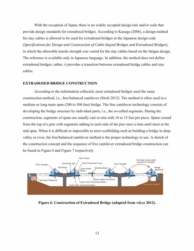
EXTRADOSED BRIDGE CONSTRUCTION
According to the information collected, most extradosed bridges used the same
construction method, i.e., free/balanced cantilever (Stroh 2012). The method is often used in a
medium or long main span (200 to 500 feet) bridge. The free cantilever technology consists of
developing the bridge structure by individual parts, i.e., the so-called segments. During the
construction, segments of spans are usually cast in-situ with 10 to 15 feet per piece. Spans extend
from the top of a pier with segments adding to each side of the pier once a time until meet at the
mid span. When it is difficult or impossible to erect scaffolding such as building a bridge in deep
valley or river, the free/balanced cantilever method is the proper technology to use. A sketch of
the construction concept and the sequence of free cantilever extradosed bridge construction can
be found in Figure 6 and Figure 7 respectively.
Figure 6. Construction of Extradosed Bridge (adapted from vsl.cz 2012).

14
Figure 7. Major Extradosed Bridge Erection Sequence (adapted from Stroh 2012)
The main advantage of the free/balanced cantilever construction method is its structural
efficiency. In this type of method, bridge segments can be prepared rapidly in-situ because the
installation and casting of segments can be processed at the same time. As an alternative,

15
segments can also be cast during the substructure construction period. An example of pylons and
pier tables, together with travelers in extradosed bridge construction with the free/balanced
cantilever method is shown in Figure 8. The disadvantage of the free/balanced cantilever method
is the possible limitation of in-situ casting space. If segments are prepared elsewhere and then
delivered to the jobsite, the transportation method needs to be considered carefully. For example,
the transportation route should be selected well and help with traffic control during
transportation will be needed.
(a) Pylon and Pier Table
(b) Form Traveler
Figure 8. Example of Free Balanced Cantilever Method for Extradosed Bridge Construction (Ritto Bridge) (adapted from tripod.com 2012).
EXTRADOSED BRIDGE MAINTENANCE
As most of extradosed bridges are still relatively new, there is not much information
regarding maintenance and repair of such bridges. However, information collected from

16
interviews conducted from this study indicated that even though there is no specific data to
support the statement, there is no reason to expect that extradosed bridges will result in higher
maintenance costs or efforts compared to other common bridge types. Compared to cable-stayed
bridges, extradosed bridges have similar inspection items, but there is likely to be lower
maintenance/inspect efforts or costs due to the lower numbers of cables and lower towers.
However, compared to girder bridges, extradosed bridges could involve higher costs and efforts
in maintenance or inspection due to the stay cables, anchorages, vibration dampers, towers,
internal anchor boxes, and grounding system (lighting protection) that would not be expected in
a typical girder bridge.
SUMMARY
The extradosed bridge has a hybrid design with the girder directly supported by resting
on part of towers while cable stays act as prestressing cables for a concrete girder. The basic role
of cables in an extradosed bridge is to provide horizontal prestress to the girder instead of to
develop elastic vertical actions, as is the case of traditional cable stays. However, there is no
widely accepted definition of an extradosed bridge. Mathivat suggested using the tower height-
to-span ratio as the differentiating feature between the two bridge types, with cable-stayed
bridges defined by tower height-to-span ratios of approximately 1/5 and extradosed bridges
defined by ratios of approximately 1/15. Meanwhile, Ogawa and Kasuga suggested defining an
extradosed bridge by the stiffness ratio (the load carried by stay cables divided by total vertical
load) of less than 30%. Further study is needed to justify what is the most appropriate definition
of an extradosed bridge. With the exception of Japan, there is no widely accepted design rule or
code that provides design standards for the extradosed bridge type. The Japanese design code
(Specifications for Design and Construction of Cable-Stayed Bridges and Extradosed Bridges) is
available only in Japanese language. The method does not define an extradosed bridge; rather, it
provides a transition between an extradosed bridge cable and a stay cable. Most of extradosed
bridges documented used the free/balanced cantilever construction method. Even though there is
no specific data to reflect maintenance costs and efforts of extradosed bridges, costs or efforts are
not expected to be higher compared to other common bridge types.

17
CHAPTER 3. REVIEW OF EXTRADOSED BRIDGES
GENERAL INFORMATION OF EXTRADOSED BRIDGES
Since the first extradosed bridge constructed in 1994, the number of extradosed bridges
being built or have been built rose quickly over the last couple decades. In order to better
understand the general configurations of extradosed bridges and trends of development, a
literature survey was conducted to summarize statuses, structural features, costs, and major
reason(s) in bridge selection from all extradosed bridges identified from literature. A total of 120
extradosed bridges from Asia, Europe, North America, South America, and Africa were
identified through the review of nearly 350 technical papers, reports, theses, dissertations, and
websites. Documents in different languages including English, Japanese, Chinese, Korean,
Vietnamese, German, Spanish, Polish, Croatian, Slovenian, Serbian, Czech, and Portuguese were
included in the study. Tools including GoogleTM translation were used for languages other than
English, Chinese, Korean, and Japanese. Appendix A lists the 120 extradosed bridges, together
with references identified for each of the bridge. A list of the 120 bridges and configurations of
bridges are presented in Table 3 and Table 4 respectively. Appendix B presents detailed
information of the 120 bridges, including photos and drawings of layouts and cross sections of
the bridges.

18
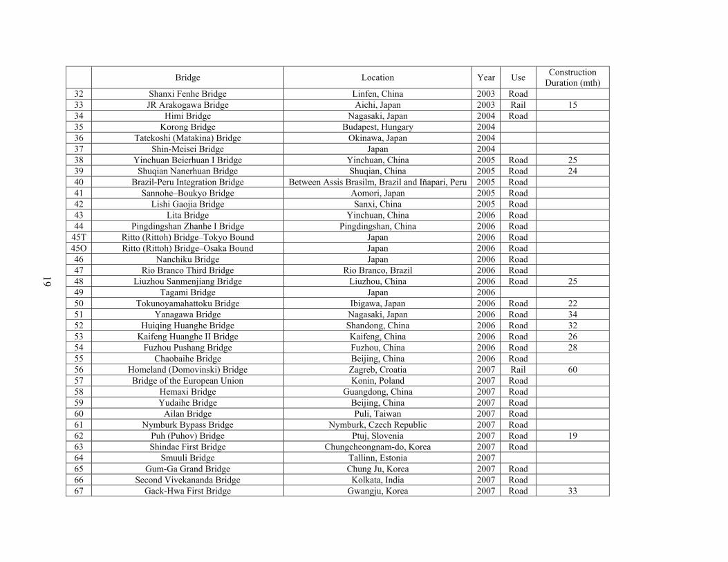
Table 3. General Information of Extradosed Bridges.
Bridge Location Year Use Construction Duration (mth)
1 Odawara Blueway Bridge Odawara, Japan 1994 Road 22 2 Tsukuhara Bridge Hyogo, Japan 1997 Road 44
3S Yashiro Bridge-South Bound Nagano, Japan 1997 Rail 3N Yashiro Bridge-North Bound Nagano, Japan 1997 Rail 4 Kanisawa Bridge Japan 1998 Road
5E Shin-Karato Bridge (Okuyama Bridge)-East Bound Kobe, Japan 1998 23 5W Shin-Karato Bridge (Okuyama Bridge)-West Bound Kobe, Japan 1998 23 6 Sunniberg Bridge Klosters, Switzerland 1998 Road 30 7 Mitanigawa Bridge (Santanigawa Bridge) Japan 1998 Road 8 Sapporo Railway Bridge Sapporo, Japan 1999 Rail 27 9 Second Mactan-Mandaue Bridge Mandaue, Philippines 1999 Road 37
10 Pont de Saint-Rémy-de-Maurienne Bridge Saint-Rémy-de-Maurienne, France 1999 Road 11 King Hussein Bridge Jordan 1999 Road 12 Pakse Bridge Between Pakse Laos and Phonthong Thailand 2000 Road 24 13 Sajiki Bridge Japan 2000 Road 14 Shikari Bridge Hokkaido, Japan 2000 Road 29 15 Surikamigawa Bridge Japan 2000 16 Wuhu Yangtze River Bridge Wuhu, China 2000 Hybrid 42 17 Yukizawa Bridge Japan 2000 Road 18 Hozu Bridge Kyoto, Japan 2001 Road 19 Ibi River Bridge (Ibigawa Bridge) Nagashima-cho, Japan 2001 Road 33 20 Kiso River Bridge (Kisogawa Bridge) Nagashima-cho, Japan 2001 Road 33 21 Miyakoda River Bridge (Miyakodagawa Bridge) Shizuoka, Japan 2001 Road 55 22 Nakanoike Bridge Japan 2001 23 Zhangzhou Zhanbei Bridge Zhangzhou, China 2001 Road 24 Fukaura Bridge Japan 2002 25 Koror-Babeldaob (Japan–Palau Friendship) Bridge Koror, Palau 2002 Road 60 26 Sashikubo Bridge Shingou-mura Japan 2002 Road 27 Shinkawa (Tobiuo) Bridge Hamamatsu, Japan 2002 Road 33 28 Tongan Yinhu Bridge Xiamen, China 2002 Road 29 Changcheng Yunhe Bridge Changzhou, China 2003 Road 15 30 Deba River Bridge Guipuzcoa, Spain 2003 Road 31 Xiaoxihu Yellow River Bridge Lanzhou, China 2003 Road 24
19
Bridge Location Year Use Construction Duration (mth)
32 Shanxi Fenhe Bridge Linfen, China 2003 Road 33 JR Arakogawa Bridge Aichi, Japan 2003 Rail 15 34 Himi Bridge Nagasaki, Japan 2004 Road 35 Korong Bridge Budapest, Hungary 2004 36 Tatekoshi (Matakina) Bridge Okinawa, Japan 2004 37 Shin-Meisei Bridge Japan 2004 38 Yinchuan Beierhuan I Bridge Yinchuan, China 2005 Road 25 39 Shuqian Nanerhuan Bridge Shuqian, China 2005 Road 24 40 Brazil-Peru Integration Bridge Between Assis Brasilm, Brazil and Iñapari, Peru 2005 Road 41 Sannohe–Boukyo Bridge Aomori, Japan 2005 Road 42 Lishi Gaojia Bridge Sanxi, China 2005 Road 43 Lita Bridge Yinchuan, China 2006 Road 44 Pingdingshan Zhanhe I Bridge Pingdingshan, China 2006 Road
45T Ritto (Rittoh) Bridge–Tokyo Bound Japan 2006 Road 45O Ritto (Rittoh) Bridge–Osaka Bound Japan 2006 Road 46 Nanchiku Bridge Japan 2006 Road 47 Rio Branco Third Bridge Rio Branco, Brazil 2006 Road 48 Liuzhou Sanmenjiang Bridge Liuzhou, China 2006 Road 25 49 Tagami Bridge Japan 2006 50 Tokunoyamahattoku Bridge Ibigawa, Japan 2006 Road 22 51 Yanagawa Bridge Nagasaki, Japan 2006 Road 34 52 Huiqing Huanghe Bridge Shandong, China 2006 Road 32 53 Kaifeng Huanghe II Bridge Kaifeng, China 2006 Road 26 54 Fuzhou Pushang Bridge Fuzhou, China 2006 Road 28 55 Chaobaihe Bridge Beijing, China 2006 Road 56 Homeland (Domovinski) Bridge Zagreb, Croatia 2007 Rail 60 57 Bridge of the European Union Konin, Poland 2007 Road 58 Hemaxi Bridge Guangdong, China 2007 Road 59 Yudaihe Bridge Beijing, China 2007 Road 60 Ailan Bridge Puli, Taiwan 2007 Road 61 Nymburk Bypass Bridge Nymburk, Czech Republic 2007 Road 62 Puh (Puhov) Bridge Ptuj, Slovenia 2007 Road 19 63 Shindae First Bridge Chungcheongnam-do, Korea 2007 Road 64 Smuuli Bridge Tallinn, Estonia 2007 65 Gum-Ga Grand Bridge Chung Ju, Korea 2007 Road 66 Second Vivekananda Bridge Kolkata, India 2007 Road 67 Gack-Hwa First Bridge Gwangju, Korea 2007 Road 33

20
Bridge Location Year Use Construction Duration (mth)
68 Pyung-Yeo II Bridge Yeosu, Korea 2008 Road 69 Dae-Ho Grand (Cho-Rack) Bridge Dangjin, Korea 2008 Road 44 70 Hirano Bridge Osaka, Japan 2008 Rail 71 Sannai–Maruyama Bypass Bridge Hachinole to Shin-Aomori, Japan 2008 Rail 36 72 Ma-Tsu Bridge Yunlin, Taiwan 2008 Road 73 North Arm Bridge Vancouver, Canada 2008 Rail 74 Sannai–Maruyama Bridge Aomori, Japan 2008 Road 75 Trois-Bassins Viaduct Bridge Reunion, France 2008 Road 33 76 Hidasie Bridge Blue Nile Gorge, Ethiopia 2008 Road 77 Riga South(ern) Bridge Riga, Latvia 2009 Road 48 78 Golden Ears Bridge Vancouver, Canada 2009 Road 79 Karnaphuli III Bridge Chittagong, Bangladesh 2009 Road 38 80 Kyong-An Bridge Kyong-An, Korea 2009 81 Husong Bridge Zhuzhou, China 2009 Road 82 Xianshen River Bridge Shanxi, China 2009 Road 83 Ankang Qiligou Bridge Shanxi, China 2009 Road 84 Incheon Bridge Incheon, Korea 2009 Road 36 85 Qishan Bridge Gaoxiong, Taiwan 2010 Road 86 Choqueyapu Bridge La Paz, Bolivia 2010 Road 87 Kantutani Bridge La Paz, Bolivia 2010 Road 88 Orkojahuira Bridge La Paz, Bolivia 2010 Road 89 Povazska Bystrica D1 Motorway Viaduct Povazska Bystrica, Slovakia 2010 Road 22 90 Teror Viaduct Gran Canaria Island, Spain 2010 Road 22 91 New Amarube Bridge Japan 2010 Rail 92 Immobility Bridge Japan 2011 Road 84 93 Un-am Grand Bridge Jeonbuk, Korea 2011 Road 86 94 Panyu Shanwan Bridge Guangzhou, China 2011 Road 95 Jiayue (Nanping) Bridge Chongqing, China 2011 Hybrid 96 Tisza Bridge More Ferenc, Hungary 2011 Road 97 Hwangdo Grand Bridge Changgi-ri, Korea 2011 Road 61 98 Nokan Bridge Busan, Korea 2011 Road 99 Guemgang I Bridge Sejong City, Korea 2012 Hybrid 52 100 Qinxiu Bridge Lugu, Taiwan 2012 Road 101 Hualiantai Fengping Bridge Hualian, Taiwan 2012 Road 30 102 Dazhihe Bridge Shanghai, China 2012 Road 103 Najin Bridge Tibet, China 2012 Road 22 104 La Massana Bridge La Massana, Andorra 2012 Road

21
Bridge Location Year Use Construction Duration (mth)
105 Naluchi Bridge Muzaffarabad, Pakistan 2012 Road 33 106 Waschmuhl Viaduct Kreos, Germany 2012 Road 107 New Pearl Harbor Memorial (Quinnipiac) Bridge New Haven, US 2012 Road 60 108 Changshan Bridge Daliang, China 2013 Road 24 109 Ningjiang Shonghuajiang Bridge Jilin, China 2013 Road 36 110 Half Sky Overpass Bridge Lugu, Taiwan 2013 Road 20 111 Yongjin Bridge Sang-ri, Korea 2014 Road 31 112 Gangchon 2nd Bridge Banggok-ri, Korea 2014 Road 113 Saint Croix River Bridge Houlton/Still Water, United States 2014 Road 114 Sanguanjiang Bridge Wuhan, China 2015 Road 42 115 Brazos River Bridge Waco, United States 2015 Road 116 Naericheon Bridge Sangnam Inje Kangwon, Korea 2015 Road 117 Yaro Grand Bridge Yaro Myun, Korea 2015 Road 54 118 Pyung-Taik Grand Bridge Pyung-Taik City, Korea 2016 Road 60 119 Beixi Hechuan Bridge Nanao, Taiwan 2016 Road 120 Kinmen Bridge Kinmen, Taiwan 2016 Road
Note: In the table, the term of “hybrid” refers to bridges serve the purpose of both road and rail (or light rail), or road with pedestrian or bike underneath.

22
Table 4. Summary of Configurations of Extradosed Bridges.
Bridge Name #c Mat #S #T Sm (ft)
St (ft) Ht (ft)
Sm/Ht
Dc/v Dm (ft)
Dt (ft)
Dw (ft)
Sm/Dm
Sm/Dt
1 Odawara Blueway Bridge 2 C 3 2x2 400 886 35.1 11.4 Var 7.2 11.5 43.6 55.5 34.9 2 Tsukuhara Bridge 1 C 3 2x2x2 591 1060 52.5 11.3 Var 9.8 18.0 42.0 60.0 32.7
3S Yashiro Bridge-South Bound C 4 3x2 344 1115 39.4 8.8 3N Yashiro Bridge-North Bound C 3 2x2 295 656 32.8 9.0 4 Kanisawa Bridge C 3 2x2 591 1242 72.5 8.1 Var 10.8 18.4 57.4 54.5 32.1
5E Shin-Karato (Okuyama) Bridge–East 2 C 3 2x2x2 394 847 39.4 10.0 Var 8.2 11.5 31.8 48.0 34.3 5W Shin-Karato (Okuyama) Bridge–West 3 C 3 2x2x2 459 929 39.4 11.7 Var 8.2 11.5 41.5 56.0 40.0 6 Sunniberg Bridge C 5 4x2 459 1726 48.6 9.5 Con 3.6 3.6 40.6 127.3 127.3 7 Mitanigawa (Santanigawa) Bridge 2 C 2 1x1 305 495 41.3 7.4 Var 8.2 21.3 66.9 37.2 14.3 8 Sapporo Railway Bridge C 2 182 364 32.5 9 Second Mactan–Mandaue Bridge 3 C 3 2x2 607 1339 59.1 10.3 Var 10.8 16.7 59.1 56.1 36.3
10 Pont de Saint-Rémy-de-Maurienne Bridge C 2 2x1 172 331 19.4 8.9 Con 7.1 7.1 44.0 24.4 24.4 11 King Hussein Bridge 3 C 3 2x2 171 394 Var 4.9 8.2 62.0 34.7 20.8 12 Pakse Bridge 1 C 3 2x2 469 1173 49.2 9.5 Var 9.8 21.3 45.3 47.7 22.0 13 Sajiki Bridge C 3 2x2 344 736 38.5 8.9 Var 6.9 10.5 36.1 50.0 32.8 14 Shikari Bridge C 5 4x1 459 1995 32.8 14.0 Var 9.8 19.7 92.1 46.7 23.3 15 Surikamigawa Bridge C 1 278 54.1 5.1 Var 9.2 16.4 30.2 30.3 17.0 16 Wuhu Yangtze River Bridge HA 3 2x2 1024 2205 114.8 8.9 Con 44.3 44.3 76.8 23.1 23.1 17 Yukizawa Bridge 2 C 2 233 464 37.7 6.2 Var 6.6 11.5 51.8 35.5 20.3 18 Hozu Bridge 1 C 3 2x2 328 827 32.8 10.0 Con 9.2 9.2 53.5 35.7 35.7 19 Ibi River Bridge (Ibigawa Bridge) 4 HB 6 5x1 891 4583 98.4 9.1 Var 14.1 24.0 108.3 63.1 37.2 20 Kiso River Bridge (Kisogawa Bridge) 4 HB 5 4x1 902 3757 98.4 9.2 Var 14.1 24.0 108.3 64.0 37.7 21 Miyakoda River (Miyakodagawa) Bridge 2 C 2 1x3 440 879 65.6 6.7 Var 13.1 21.3 65.3 33.5 20.6 22 Nakanoike Bridge 2 199 398 38.7 5.1 Var 8.2 13.1 70.2 24.2 15.2 23 Zhangzhou Zhanbei Bridge 3 C 3 2x1 433 963 54.1 8.0 Var 7.9 12.5 88.6 55.0 34.7 24 Fukaura Bridge 5 295 959 27.9 10.6 Var 8.2 9.8 44.9 36.0 30.0 25 Koror-Babeldaob (Japan-Palau Friendship) Bridge HB 3 2x2 810 1348 87.3 9.3 Var 11.5 23.0 38.1 70.6 35.3 26 Sashikubo Bridge C 2 1x2 374 748 72.2 5.2 Var 10.5 21.3 37.1 35.6 17.5 27 Shinkawa (Tobiuo) Bridge 3 C 3 2x1 427 986 42.7 10.0 Var 7.9 13.1 84.6 54.2 32.5 28 Tongan Yinhu Bridge 3 C 2 1x1 262 525 103.3 2.5 Var 7.9 12.5 88.6 33.3 21.1 29 Changcheng Yunhe Bridge 3 C 3 2x2 394 854 101.7 3.9 Var 8.5 13.5 91.9 46.2 29.3 30 Deba River Bridge C 3 2x2 217 492 39.0 5.5 Con 8.9 8.9 45.6 24.4 24.4 31 Xiaoxihu Yellow River Bridge 3 C 3 2x2 446 979 55.8 8.0 Var 8.5 14.8 90.2 52.3 30.2 32 Shanxi Fenhe Bridge C 3 2x3 492 1083 118.1 4.2 85.3

23
Bridge Name #c Mat #S #T Sm (ft)
St (ft) Ht (ft)
Sm/Ht
Dc/v Dm (ft)
Dt (ft)
Dw (ft)
Sm/Dm
Sm/Dt
33 JR Arakogawa Bridge C 3 295 659 29.5 10.0 Con 8.5 8.5 41.7 34.6 34.6 34 Himi Bridge 1 HA 3 2x2 591 1193 65.0 9.1 Con 13.1 13.1 42.5 45.0 45.0 35 Korong Bridge 3 C 2 1x2 203 375 32.2 6.3 Con 8.2 8.2 52.0 24.8 24.8 36 Tatekoshi (Matakina) Bridge C 2 1x2 185 369 34.4 5.4 Var 5.9 9.5 62.8 31.3 19.4 37 Shin-Meisei Bridge 3 C 3 2x1 401 958 54.1 7.4 Con 11.5 11.5 62.3 35.0 35.0 38 Yinchuan Beierhuan I Bridge 4 C 2 1x2 230 459 95.1 2.4 Con 7.9 7.9 196.2 28.9 28.9 39 Shuqian Nanerhuan Bridge 3 C 3 2x1 361 794 45.9 7.9 Var 7.2 11.5 65.6 50.0 31.4 40 Brazil-Peru Integration Bridge 1 C 3 2x2 361 787 49.2 7.3 Var 7.7 11.0 55.1 46.8 32.8 41 Sannohe-Boukyo Bridge 2 C 3 2x2 656 1312 82.0 8.0 Var 11.5 21.3 44.1 57.1 30.8 42 Lishi Gaojia Bridge 3 C 3 2x1 443 1001 59.1 7.5 Var 7.9 13.8 85.3 56.3 32.1 43 Lita Bridge 2 C 94.5 196.8 44 Pingdingshan Zhanhe I Bridge C 2 1x1 289 525 74.5 3.9 Var 7.2 13.1 98.4 40.0 22.0
45T Ritto (Rittoh) Bridge–Tokyo Bound 3 HA 2 1x2 558 1009 100.1 5.6 Var 14.8 24.6 64.3 37.8 22.7 45O Ritto (Rittoh) Bridge–Osaka Bound 3 HA 2 1x2 525 1026 100.1 5.2 Var 14.8 24.6 64.3 35.6 21.3 46 Nanchiku Bridge 3 C 3 2x2 361 807 36.1 10.0 Var 8.5 11.5 67.4 42.3 31.4 47 Rio Branco Third Bridge C 3 2x2 295 650 39.7 7.4 Var 6.6 8.2 69.2 45.0 36.0 48 Liuzhou Sanmenjiang Bridge 2 C 3 2x2 525 1181 72.2 7.3 Var 8.2 22.0 134.5 64.0 23.9 49 Tagami Bridge 2 263 526 47.6 5.5 Var 9.8 14.8 58.4 26.7 17.8 50 Tokunoyamahattoku Bridge 1 C 3 2x2 722 1638 73.8 9.8 Var 11.5 21.3 31.5 62.9 33.8 51 Yanagawa Bridge 2 C 2 1x2 429 858 78.7 5.4 Var 13.1 21.3 57.1 32.7 20.1 52 Huiqing Huanghe Bridge 3 C 3 2x1 722 1594 99.4 7.3 Var 13.1 24.6 65.6 55.0 29.3 53 Kaifeng Huanghe II Bridge 8 7x2 459 3314 118.1 3.9 98.4 54 Fuzhou Pushang Bridge 4 3x2 361 1194 88.6 4.1 109.9 55 Chaobaihe Bridge 3 C 4 3x1 394 1260 70.5 5.6 Var 7.2 13.8 96.8 54.5 28.6 56 Homeland (Domovinski) Bridge 5 C 3 2x2 394 866 54.1 7.3 Con 11.6 11.6 109.9 33.8 33.8 57 Bridge of the European Union 3 2x3 262 656 33.8 7.8 82.3 58 Hemaxi Bridge 3 C 3 2x1 755 1575 128.0 5.9 Var 9.8 21.3 92.8 76.7 35.4 59 Yudaihe Bridge 4 3x2 279 853 92.2 3.0 109.9 60 Ailan Bridge C 3 2x1 459 984 65.6 7.0 Var 9.8 16.7 85.1 46.7 27.5 61 Nymburk Bypass Bridge HA 3 2x2 433 702 52.5 8.3 Var 7.5 54.6 57.4 62 Puh (Puhov) Bridge 1 C 5 4x2 328 1411 27.9 11.8 Con 8.9 8.9 61.4 37.0 37.0 63 Shindae First Bridge 4 256 807 39.4 6.5 70.8 64 Smuuli Bridge C 3 2x2 279 554 65 Gum-Ga Grand Bridge C 7 6x2 410 2610 29.0 14.1 75.5 66 Second Vivekananda Bridge C 9 8x2 361 2707 45.9 7.9 Con 11.2 11.2 95.1 32.4 32.4 67 Gack-Hwa First Bridge C 2 1x2 377 705 75.5 5.0 Var 11.6 16.3 102.0 32.5 23.1 68 Pyung-Yeo II Bridge 4 C 3 2x2 394 820 34.4 11.4 Var 11.5 13.1 68.9 34.3 30.0

24
Bridge Name #c Mat #S #T Sm (ft)
St (ft) Ht (ft)
Sm/Ht
Dc/v Dm (ft)
Dt (ft)
Dw (ft)
Sm/Dm
Sm/Dt
69 Dae-Ho Grand (Cho-Rack) Bridge 2 C 5 4x2 427 1739 54.1 7.9 Var 8.2 11.5 45.9 52.0 37.1 70 Hirano Bridge C 207 71 Sannai-Maruyama Bypass Bridge 2 C 4 3x2 492 1476 72 Ma-Tsu Bridge C 410 820 114.8 3.6 Var 8.2 19.7 88.6 50.0 20.8 73 North Arm Bridge 1 C 3 2x1 591 1503 59.1 10.0 Var 9.2 19.0 33.8 64.3 31.0 74 Sannai-Maruyama Bridge 4 C 4 3x2 492 1471 57.4 8.6 Var 12.5 26.2 45.4 39.5 18.8 75 Trois-Bassins Viaduct Bridge 1 HA 413 1004 62.3 6.6 Var 13.1 23.0 72.2 31.5 18.0 76 Hidasie Bridge 476 994 77 Riga South(ern) Bridge 7 6x1 361 2635 43.7 8.3 112.5 78 Golden Ears Bridge 1 HB 794 3176 136.2 5.8 Var 8.9 14.8 105.0 89.6 53.8 79 Karnaphuli III Bridge 1 C 5 656 2723 84.5 7.8 Var 13.1 22.1 80.3 50.0 29.6 80 Kyong-An Bridge 4 C 3 2x1 427 886 53.5 8.0 Con 9.8 9.8 98.4 43.3 43.3 81 Husong Bridge 3 C 4 3x1 459 1411 61.7 7.4 Var 9.2 14.3 95.1 50.0 32.2 82 Xianshen River Bridge C 2 1x1 446 876 160.8 2.8 83 Ankang Qiligou Bridge C 3 2x1 410 886 114.2 3.6 98.4 84 Incheon Bridge 3 C 3 2x2 459 1010 Var 59.3 85 Qishan Bridge 328 656 Var 9.2 16.4 72.8 35.7 20.0 86 Choqueyapu Bridge 1 C 3 2x1 303 628 49.2 6.2 Var 6.9 11.5 45.9 44.0 26.4 87 Kantutani Bridge 1 C 3 2x1 372 766 49.2 7.6 Var 6.9 11.5 45.9 54.0 32.4 88 Orkojahuira Bridge 1 C 3 2x1 338 718 49.2 6.9 Var 6.9 11.5 45.9 49.0 29.4 89 Povazska Bystrica D1 Motorway Viaduct HA 8 7x1 400 2857 46.3 8.7 Con 19.7 19.7 100.6 20.3 20.3 90 Teror Viaduct C 3 2x2 476 856 52.5 9.1 91 New Amarube Bridge 1 C 4 3x2 271 886 16.4 16.5 Con 11.5 11.5 23.8 23.6 23.6 92 Immobility Bridge 1 C 4 3x2 509 1717 Var 42.7 93 Un-am Grand Bridge C 6 5x1 427 2198 26.2 16.3 Var 10.8 13.8 75.5 39.4 31.0 94 Panyu Shanwan Bridge 3 C 3 2x1 338 728 123.0 2.7 Var 13.1 27.9 111.5 25.8 12.1 95 Jiayue (Nanping) Bridge C 3 2x2 623 1260 90.2 96 Tisza Bridge 3 HA 3 2x1 591 52.5 11.3 Var 13.1 19.7 98.2 45.0 30.0 97 Hwangdo Grand Bridge 2 C 3 2x2 459 984 45.9 10.0 Var 8.2 13.1 47.2 56.0 35.0 98 Nokan Bridge HA 230 459 Var 73.3 99 Guemgang I Bridge 3 C 5 4x2 591 2428 85.3 6.9 98.4
100 Qinxiu Bridge C 3 2x1 384 39.4 101 Hualiantai Fengping Bridge 5 C 4 3x1 459 1470 55.8 8.2 Var 8.7 15.7 92.5 52.8 29.2 102 Dazhihe Bridge C 3 2x1 459 984 67.3 6.8 103 Najin Bridge 1 C 4 3x1 361 1181 108.3 104 La Massana Bridge 1x2x2 105 Naluchi Bridge C 2 1x2 400 800 78.7 5.1 Var 11.5 23.0 51.2 34.8 17.4

25
Bridge Name #c Mat #S #T Sm (ft)
St (ft)
Ht (ft)
Sm/Ht
Dc/v Dm (ft)
Dt (ft)
Dw (ft)
Sm/Dm
Sm/Dt
106 Waschmuhl Viaduct 3 2x2 62.8 107 New Pearl Harbor Memorial (Quinnipiac) Bridge 5 C 3 2x3 515 1013 69.9 7.4 Var 11.3 16.2 110.6 45.7 45.7 108 Changshan Bridge 3 2x2 853 1772 84.5 10.1 75.5 109 Ningjiang Shonghuajiang Bridge 3 C 5 4x1 492 2100 Var 9.8 18.0 86.9 50.0 27.3 110 Half Sky Overpass Bridge 3 2x1 1214 49.2 111 Yongjin Bridge 3 C 3 2x2 443 984 44.3 10.0 Var 8.2 14.8 50.9 54.0 30.0 112 Gangchon 2nd Bridge 3 C 3 2x2 459 1004 59.1 7.8 Var 9.0 16.4 64.6 50.9 28.0 113 Saint Croix River Bridge 3 C 8 7x2 480 3460 60.0 8.0 Con 16.0 16.0 110.0 30.0 30.0 114 Sanguanjiang Bridge 3 2x1 623 1411 109.9 115 Brazos River Bridge S 3 2x2x2 250 620 46.0 5.4 Con 56.5 116 Naericheon Bridge C 2 1x1 509 902 Var 100.1 117 Yaro Grand Bridge 3 2x1 623 1804 89.2 7.0 Var 11.5 23.0 88.6 54.3 27.1 118 Pyung-Taik Grand Bridge 8 7x1 525 3806 67.3 7.8 Var 11.5 18.0 98.1 45.7 29.1 119 Beixi Hechuan Bridge 3 2x1 525 1181 120 Kinmen Bridge 6 5x1 919 4593
Note: In the table, #c refers to the number of cells, Mat refers to girder materials (concrete, steel, or hybrid), #S refers to number of spans, #T refers to number of
towers, Sm refers to main span length (in feet), St refers to total span length (in feet), Ht refers to tower height (in feet), Sm/Ht refers main span to tower height
ratio, Dc/v refers to thickness of girder (constant or variance), Dm refers to girder thickness at mid-spans (in feet), Dt refers to girder thickness at towers (in feet),
Dw refers to girder width (in feet), Sm/Dm refers to main span length to girder thickness at mid-span ratio, and Sm/Dt refers to main span length to girder thickness
at tower ratio.
26
Statistical analyses were performed based on the information collected through literature
survey and interviews. Results are shown in the following sections.
LOCATIONS AND CONSTRUCTION TIME OF EXTRADOSED BRIDGES
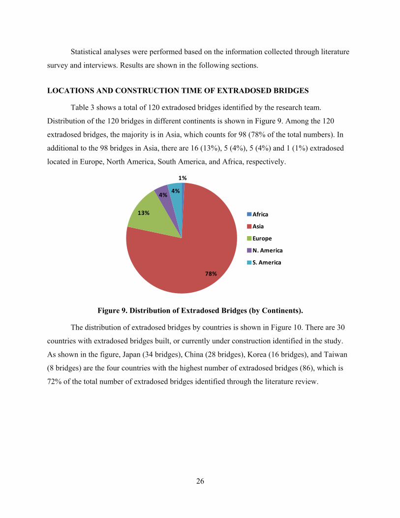
Table 3 shows a total of 120 extradosed bridges identified by the research team.
Distribution of the 120 bridges in different continents is shown in Figure 9. Among the 120
extradosed bridges, the majority is in Asia, which counts for 98 (78% of the total numbers). In
additional to the 98 bridges in Asia, there are 16 (13%), 5 (4%), 5 (4%) and 1 (1%) extradosed
located in Europe, North America, South America, and Africa, respectively.
1%
78%
13%
4%4%
Africa
Asia
Europe
N. America
S. America
Figure 9. Distribution of Extradosed Bridges (by Continents).
The distribution of extradosed bridges by countries is shown in Figure 10. There are 30
countries with extradosed bridges built, or currently under construction identified in the study.
As shown in the figure, Japan (34 bridges), China (28 bridges), Korea (16 bridges), and Taiwan
(8 bridges) are the four countries with the highest number of extradosed bridges (86), which is
72% of the total number of extradosed bridges identified through the literature review.

27
1 13
1 1 2
28
1 1 1 1 2 1 2 1
34
1
16
1 1 1 1 1 1 1 1 2 1
8
3
0
5
10
15
20
25
30
35
40
Andorra
Bangladesh
Bolivia
Brazil
Brazil/Peru
Canada
China
Croatia
Czech
Estonia
Ethiopia
France
Germ
any
Hungary
India
Japan
Jordan
Korea
Laos/Thailand
Latvia
Pakistan
Palau
Philippines
Poland
Slovakia
Slovenia
Spain
Switzerland
Taiwan
United States
Count (Out of 120)
Figure 10. Distribution of Extradosed Bridges (by Countries).
As shown in Figure 11, since construction of the very first extradosed bridge (Odawara
Blueway Bridge) was completed in 1994, there is a steady growth in the number of extradosed
bridges, with most of the bridges constructed in the last decade. The highest number of
extradosed bridges identified is in 2006, with a total of 14 bridges constructed. Due to the
limitation of available information, the list of extradosed bridges identified in the study,
especially in recent years (since 2006), might not be completed and therefore the number of
extradosed bridges could be lower than the actual number. There are also approximately 20
identified bridges currently under construction or in the design phase. Among the five bridges
identified in North America, there are two in Canada and three in the United States. The two
bridges in Canada are North Arm Bridge (completed in 2008) and Golden Ear Bridge (completed
in 2009). The three bridges in United States are the New Pearl Harbor Memorial Bridge (to be
completed in 2015; north bound was opened in summer 2012) in Connecticut, the St. Croix
River Bridge (to be completed in 2014) between Minnesota and Wisconsin, and the Brazos River
Bridge at Waco, Texas (broke ground in summer 2012 and to be completed in 2015).

28
1
2
4 4
6 6
5 5
4
5
13
12
9
8
7 7
9
0
2
4
6
8
10
12
14
Counts (out of 120)
Figure 11. Distribution of Extradosed Bridges (by Completion Year).
As shown in Figure 12, construction duration of the extradosed bridges spread in a wide
range, with a minimum of 15 months (Changcheng Yunhe Bridge and JR Arakogawa Bridge,
both completed in 2003) and a maximum of 86 months (Unam Grand Bridge, completed in
2011). While most of the bridges were constructed within 20 and 40 months, the average
construction duration was found to be 36 months.
15
27
8
229% 52% 15% 4%
0
5
10
15
20
25
30
0 to 24 25 to 48 49 to 72 73 to 96 > 96
Count (%
out of 52)
Construction Duration, mths
Figure 12. Distribution of Construction Duration.

29
PURPOSES AND USAGE OF EXTRADOSED BRIDGES
According to the literature review, the four typical purposes (uses) of extradosed bridges
are road bridge, railway or light rail bridge, road and railway hybrid bridge, and road and
pedestrian hybrid bridge. Examples of these typical purposes (uses) of extradosed bridges are
shown in Figure 13.
(a). Road (Ritto Bridge)
(b). Railway or Light Rail (North Arm Bridge)
(c). Road and Railway Hybrid (Wuhu Yangtze River Bridge)
(d). Road and Pedestrian Hybrid (Guemgang I Bridge)
Figure 13. Extradosed Bridges Serving Different Purposes.
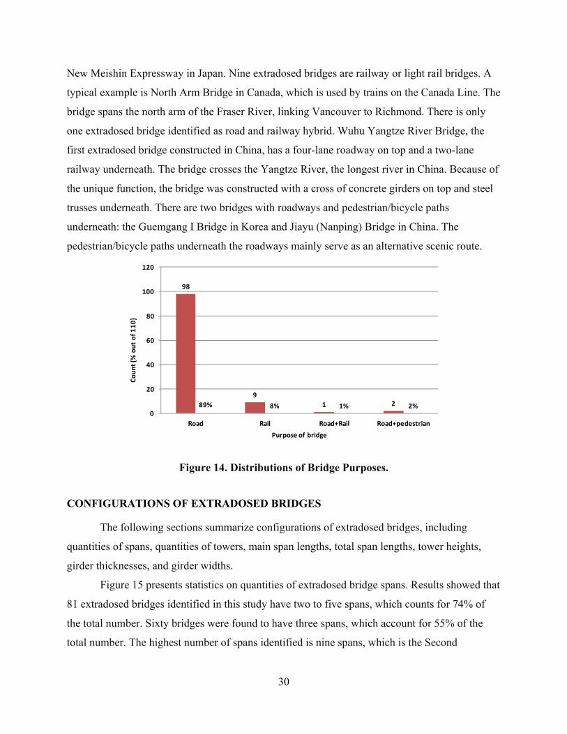
Statistics on the different purposes (uses) of extradosed bridges are shown in Figure 14.
As shown in the figure, the majority of extradosed bridges are road bridges, with 98 bridges and
89% of the total extradosed bridges identified. Road bridges connect the different sides of rivers,
valleys, and viaducts, etc. A typical example is the Ritto Bridge, located in Siga Prefecture on the
30
New Meishin Expressway in Japan. Nine extradosed bridges are railway or light rail bridges. A
typical example is North Arm Bridge in Canada, which is used by trains on the Canada Line. The
bridge spans the north arm of the Fraser River, linking Vancouver to Richmond. There is only
one extradosed bridge identified as road and railway hybrid. Wuhu Yangtze River Bridge, the
first extradosed bridge constructed in China, has a four-lane roadway on top and a two-lane
railway underneath. The bridge crosses the Yangtze River, the longest river in China. Because of
the unique function, the bridge was constructed with a cross of concrete girders on top and steel
trusses underneath. There are two bridges with roadways and pedestrian/bicycle paths
underneath: the Guemgang I Bridge in Korea and Jiayu (Nanping) Bridge in China. The
pedestrian/bicycle paths underneath the roadways mainly serve as an alternative scenic route.
98
9
1 289% 8% 1% 2%0
20
40
60
80
100
120
Road Rail Road+Rail Road+pedestrian
Count (%
out of 110)
Purpose of bridge
Figure 14. Distributions of Bridge Purposes.
CONFIGURATIONS OF EXTRADOSED BRIDGES
The following sections summarize configurations of extradosed bridges, including
quantities of spans, quantities of towers, main span lengths, total span lengths, tower heights,
girder thicknesses, and girder widths.
Figure 15 presents statistics on quantities of extradosed bridge spans. Results showed that
81 extradosed bridges identified in this study have two to five spans, which counts for 74% of
the total number. Sixty bridges were found to have three spans, which account for 55% of the
total number. The highest number of spans identified is nine spans, which is the Second

31
Vivekananda Bridge in India (see Figure 16a), with a main span of 361 feet and a total span of
2707 feet. There are a total of 19 bridges with only two spans; an example is the Yanagawa
Bridge in Japan (see Figure 16b), with a main span of 429 feet and a total span of 858 feet.
19
60
129
3 24
117% 55% 11% 8% 3% 2% 4% 1%0
10
20
30
40
50
60
70
2 3 4 5 6 7 8 9
Count (%
out of 110)
Number of Spans Figure 15. Distribution of Quantities of Spans.
(a). Second Vivekananda Bridge (9 spans) (b). Yanagawa Bridge (2 spans)
Figure 16. Examples of Bridges with the Highest and Lowest Number of Spans.
Figure 17 presents statistics on quantities of extradosed bridge towers. Note that, in this
report, the first number indicated the quantity of towers in girder direction and the second
number indicated the quantity of towers across the girder. For example, a 4×2 tower quantity of
the Golden Ear Bridge (shown in Figure 18b) indicated four towers in traffic direction (five
spans) and two towers across the girder, with a total of eight towers. Results showed that, as the
majority of extradosed bridges have three spans; the majority of tower quantities are 2×1 and
2×2. Overall, most of the bridges have either one (Figure 18c) or two (Figure 18b) towers across
the girder. There are a total of four bridges with three towers across the girder (Figure 18a), with

32
the middle tower separating the two lanes in opposite directions. In addition, four bridges
identified in the study have two separate sets of towers (Figure 18d), with each set supporting
each opposite direction.
5
8
1 1
23
31
3 34
7
34
3
1 12 2
1
0
5
10
15
20
25
30
35
Counts (%
out of 103)
Number of Towers Figure 17. Distribution of Number of Towers.
(a). Miyakoda River (Miyakodagawa) Bridge (1×3) (b). Golden Ear Bridge (4×2)
(c). Zhangzhou Zhanbei Bridge (2×1) (d). Tsukuhara Bridge (2×2×2)
Figure 18. Examples of Extradosed Bridges with Different Numbers of Towers.
Figure 19 and Figure 20 show the statistics on main span and total span lengths. Note that
all numbers included here represent the number of extradosed spans; the traditional girder spans
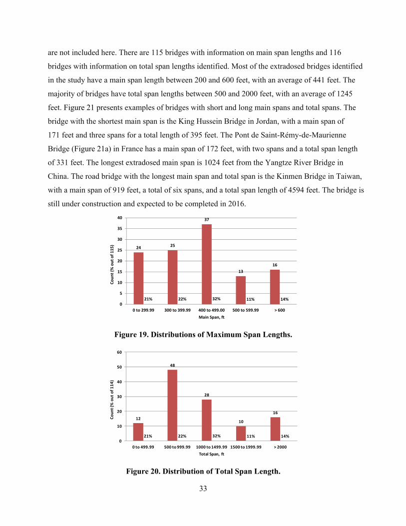
33
are not included here. There are 115 bridges with information on main span lengths and 116
bridges with information on total span lengths identified. Most of the extradosed bridges identified
in the study have a main span length between 200 and 600 feet, with an average of 441 feet. The
majority of bridges have total span lengths between 500 and 2000 feet, with an average of 1245
feet. Figure 21 presents examples of bridges with short and long main spans and total spans. The
bridge with the shortest main span is the King Hussein Bridge in Jordan, with a main span of
171 feet and three spans for a total length of 395 feet. The Pont de Saint-Rémy-de-Maurienne
Bridge (Figure 21a) in France has a main span of 172 feet, with two spans and a total span length
of 331 feet. The longest extradosed main span is 1024 feet from the Yangtze River Bridge in
China. The road bridge with the longest main span and total span is the Kinmen Bridge in Taiwan,
with a main span of 919 feet, a total of six spans, and a total span length of 4594 feet. The bridge is
still under construction and expected to be completed in 2016.
24 25
37
13
16
21% 22% 32% 11% 14%0
5
10
15
20
25
30
35
40
0 to 299.99 300 to 399.99 400 to 499.00 500 to 599.99 > 600
Count (%
out of 115)
Main Span, ft
Figure 19. Distributions of Maximum Span Lengths.
12
48
28
10
16
21% 22% 32% 11% 14%0
10
20
30
40
50
60
0 to 499.99 500 to 999.99 1000 to 1499.99 1500 to 1999.99 > 2000
Count (%
out of 114)
Total Span, ft
Figure 20. Distribution of Total Span Length.
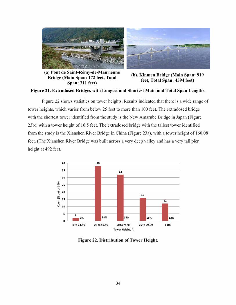
34
(a) Pont de Saint-Rémy-de-Maurienne Bridge (Main Span: 172 feet, Total
Span: 311 feet)
(b). Kinmen Bridge (Main Span: 919 feet, Total Span: 4594 feet)
Figure 21. Extradosed Bridges with Longest and Shortest Main and Total Span Lengths.
Figure 22 shows statistics on tower heights. Results indicated that there is a wide range of
tower heights, which varies from below 25 feet to more than 100 feet. The extradosed bridge
with the shortest tower identified from the study is the New Amarube Bridge in Japan (Figure
23b), with a tower height of 16.5 feet. The extradosed bridge with the tallest tower identified
from the study is the Xianshen River Bridge in China (Figure 23a), with a tower height of 160.08
feet. (The Xianshen River Bridge was built across a very deep valley and has a very tall pier
height at 492 feet.
2
38
32
16
12
2% 38% 32% 16% 12%0
5
10
15
20
25
30
35
40
0 to 24.99 25 to 49.99 50 to 74.99 75 to 99.99 >100
Count (%
out of 100)
Tower Height, ft
Figure 22. Distribution of Tower Height.

35
(a) Xianshen River Bridge (Tower Height 160.8 Feet)
(b) New Amarube Bridge (Tower Height 16.5 Feet)
Figure 23. Extradosed Bridges with the Tallest and Shortest Towers.
Main span length to tower height ratios were calculated and shown in Figure 24. Results
indicated that, in a total of 98 bridges with the information identified, most of the bridges have
the ratio between 4 and 12, with a maximum value of 16.5 (the New Amarube Bridge, completed
in 2010 in Japan; see Figure 25b) and a minimum value of 2.4 (the Yinchuan Beierhuan I Bridge,
completed in 2004 in China; see Figure 25a). Note that, while most of bridges have their cables
reach (or nearly reach) the highest points of the towers, there are approximately 10% of the
extradosed bridges constructed with towers approximately 15% to 25% taller than the highest
points of the cables (Figure 25a). The main span-to-height ratio therefore could be 15% to 25%
higher in these specific bridges. While it is believed that this is likely due to aesthetic
considerations, there is generally no accurate data available regarding the exact heights of cables.
Regardless of the abovementioned impacts, the majority of extradosed bridges identified
in the study have main span-to-tower height ratios between 1/6 and 1/9, with an average of 1/7.7.
The result is very different from what Mathivat stated (extradosed bridges generally have a main
span-to-tower height ratio of approximately 1/15, comparing to a value of approximately 1/5 for
cable-stayed bridges). The trend indicated that the definition of extradosed bridges according to
Mathivat (1998) might not be appropriate. Ogawa and Kasuga’s (1998) definition of using the
stiffness ratio (the load carried by stay cables divided by the total vertical load) and a boundary
value of 30% to distinguish a cable-stayed bridge and an extradosed bridge (with a stiffness ratio
of less than 30% to be considered as an extradosed bridge) therefore might be more appropriate.

36
4
22
44
24
4
4% 22% 45% 24% 4%0
5
10
15
20
25
30
35
40
45
50
>1/3 1/6 to 1/3 1/6 to 1/9 1/9 to 1/12 <1/12
Count (%
out of 98)
Tower Height to Main Span Ratio
Figure 24. Distribution of Main Span-Height Ratio.
(a). Yinchuan Beierhuan I Bridge (Ratio of 2.4)
(b). New Amarube Bridge (Ratio of 16.5)
Figure 25. Extradosed Bridges with Highest and Lowest Span-Tower Height Ratios.
While cable-stayed bridges typically have constant girder thicknesses, girder bridges
normally have variable girder thicknesses, i.e., with a thicker girder at the piers and thinner
girder at the mid-spans. Extradosed bridges can have either a constant (Figure 26a) or various
girder thickness (Figure 26b). As shown in Figure 27, within the 92 extradosed bridges identified
with such kind of information, 73 bridges (79% of the total) have variable girder thicknesses, and
19 bridges (21% of the total) have constant girder thicknesses.
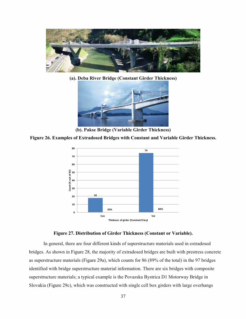
37
(a). Deba River Bridge (Constant Girder Thickness)
(b). Pakse Bridge (Variable Girder Thickness)
Figure 26. Examples of Extradosed Bridges with Constant and Variable Girder Thickness.
18
74
20% 80%
0
10
20
30
40
50
60
70
80
Con Var
Count (%
out of 92)
Thickness of girder (Constant/Vary)
Figure 27. Distribution of Girder Thickness (Constant or Variable).
In general, there are four different kinds of superstructure materials used in extradosed
bridges. As shown in Figure 28, the majority of extradosed bridges are built with prestress concrete
as superstructure materials (Figure 29a), which counts for 86 (89% of the total) in the 97 bridges
identified with bridge superstructure material information. There are six bridges with composite
superstructure materials; a typical example is the Povazska Bystrica D1 Motorway Bridge in
Slovakia (Figure 29c), which was constructed with single cell box girders with large overhangs

38
supported by precast struts. Another type of composite superstructure material is the concrete box
girders near piers and steel box girders in center. Examples of this kind of bridge are the
Koror-Babeldaob (Japan–Palau Friendship) Bridge in Palau (Figure 29d), and the Ibi River Bridge
and the Kiso River Bridge, both in Japan. According to Kasuga (1998), in the construction of the
Ibi River Bridge and the Kiso River Bridge, the free cantilevering method was adapted using 400
tons precast segments, and the 328-foot center parts are steel girders constructed by a lifting
method. The method was considered the most economic for bridges over the mouth of the wide
river. There is one bridge identified in the study with steel girders: the Brazos River Bridge in
Waco, Texas, which is to be constructed with continuous steel trapezoidal box girders.
6 4
86
16% 4% 89% 1%0
10
20
30
40
50
60
70
80
90
100
Composite‐A Composite‐B Concrete Steel
Count (%
out of 97)
Type of girder materials
Figure 28. Distribution of Superstructure Materials.

39
(a). Concrete girder–Sannai-
MaruyamaBridge (b) Steel girder–Brazos River Bridge
(c). Composite A–Povazska Bystrica D1 Motorway Bridge
(d). Composite B–Koror-Babeldaob (Japan–Palau Friendship) Bridge Figure 29. Examples of Extradosed Bridges with Different Superstructure Materials.
Figure 30 shows examples of girder cross sections with different quantities of cells in box
girders. Details of girders with various numbers of cells, together with drawings of cross sections
of different bridges, can be found in Appendix A. As summarized in Figure 31, the majority of
extradosed bridges were constructed with one to three cells, within which 37% of the total
bridges were constructed with three-cell box girders. The example showed with two and three
cells is the Shin-Karato Bridge (Okuyama Bridge), which has two cells east bound and three
cells west bound.

40
(a). Tsukuhara Bridge with Wide Single Cell Concrete Box Girder
(b). Odawara Blueway Bridge with Wide Double Cell Concrete Box Girder
(c). Shin-Meisei Bridge with Three Cell Concrete Trapezoidal Box
Girder
(d). Yinchuan Beierhuan I Bridge with Wide Four
Cell Concrete Box Girder(e). Hualiantai Fengping Bridge
with Five Cell Concrete Box GirderFigure 30. Examples of Girder with Different Numbers of Cells in Box Girders.
16
12
1
24
6
3
26% 19% 2% 39% 10% 5%0
5
10
15
20
25
30
1 2 2 and 3 3 4 5
Count (%
out of 62)
Number of Cells
Figure 31. Distribution of Number of Cells.
As shown in Figure 32 and Figure 33, while most of extradosed bridges show girder
depths at midspan between 5 to 15 feet, girder depths at piers range from 5 feet up to 30 feet. The
thinnest girder was identified as Sunniberg Bridge in Switzerland, with a constant girder
thickness of 3.6 feet (Figure 34a). The thickest girder was identified as Wuhu Yangtze River
Bridge in China, with a constant girder thickness of 44.3 feet. It should be noted that the bridge
was constructed with a double-girder steel truss with composite girder slabs on the top roadway

41
and rail lines at the bottom level. The constant girder road bridge with the girder thickness was
identified as the Povazska Bystrica D1 Motorway Viaduct in Slovakia, with a girder thickness of
19.7 feet (Figure 34b). The variable girder thickness bridge with the thickest girder was
identified as the Panyu Shawan Bridge in China, with a variable girder thickness of 13.1 feet at
midspan and 27.9 at piers (Figure 34c).
3
36
31
12
3
4% 42% 36% 14% 4%0
5
10
15
20
25
30
35
40
0 to 5.99 6 to 8.99 9 to 11.99 12 to 14.99 > 15
Count (%
out of 85)
Girder Depth at MidSpan, ft
Figure 32. Distribution of Girder Depth at Midspan.
13
32
18 18
3
15% 38% 21% 21% 4%0
5
10
15
20
25
30
35
0 to 9.99 10 to 14.99 15 to 19.99 20 to 24.99 > 25
Count (%
out of 84)
Girder Depth at Tower, ft
Figure 33. Distribution of Girder Depth at Tower.

42
(a). Sunniberg Bridge (with Constant Girder Thickness of 3.6 Feet)
(b). Wuhu Yangtze River Bridge (with Constant Girder Thickness of 44.3 Feet)
(c). Povazska Bystrica D1 Motorway Viaduct (with Constant Girder Thickness of 19.7
Feet)
(d). Panyu Shawan Bridge (with Variable Girder Thickness of 13.1 Feet at Midspans and
27.9 Feet at Piers) Figure 34. Examples of Bridges with Different Girder Thicknesses.
Calculated span length to girder thickness at midspan and pier ratios are shown in Figure
35 and Figure 36. Average values of span length to girder thickness at midspan and pier ratios
were found to be 45.4 and 30.0, respectively.

43
10
29
36
7
3
4% 42% 36% 14% 4%0
5
10
15
20
25
30
35
40
0 to 29.99 30 to 44.99 45 to 59.99 60 to 74.99 > 75
Count (%
out of 85)
Main Span to Girder Depth at MidSpan Ratio
Figure 35. Distribution of Span/Depth Ratio (Midspan).
10
32
36
3 212% 39% 43% 4% 2%
0
5
10
15
20
25
30
35
40
0 to 19.99 20 to 29.99 30 to 39.99 40 to 49.99 > 50
Count (%
out of 83)
Main Span to Girder Depth at Tower Ratio
Figure 36. Distribution of Span/Depth Ratio (Tower).
The bridge with the highest span-to-deck depth ratio at both midspan and piers is the
Sunniberg Bridge in Switzerland (completed in 1998). It was constructed with a very thin
constant girder thickness of 3.6 feet and a relatively long main span of 459 feet, which resulted
in a span-to-deck depth ratio of 127.3. The bridge with the lowest span-to-deck depth ratio at
midspan is the Povazska Bystrica D1 Motorway Viaduct in Slovakia (competed in 2010). This
was constructed with a main span length of 400 feet, and a constant girder thickness of 19.7 feet,
which resulted in a calculated span-to-depth ratio of 20.3. The bridge with the lowest span to
deck depth ratio at towers is the Panyu Shanwan Bridge in China (completed in 2011). It was
constructed with 814 feet of main span, and a girder thickness of 27.9 feet at the towers, which
resulted in a calculated span-to-depth ratio of 12.1.

44
There are 108 bridges identified with girder width information. The average girder width
was found to be at 74.0 feet. The widest girder identified was the Lita Bridge in China
(completed in 2006) with a girder width of 196.8 feet and the narrowest girder identified was the
New Amarube Bridge in Japan (completed in 2010). The bridge was a railway bridge, with a
girder width of 23.8 feet.
1
40
35
31
3
1% 36% 32% 28% 3%0
5
10
15
20
25
30
35
40
45
0 to 29.99 30 to 59.99 60 to 89.99 90 to 119.99 > 120
Count (%
out of 108)
Deck Width, ft
Figure 37. Distribution of Girder Width.
Table 5 shows a summary of statistics on extradosed bridge configurations, including
main span lengths, total span lengths, tower heights, main span-to-tower height ratios, girder
depths at midspan and tower, girder widths, main span to girder depths ratios at midspan and
tower. Detailed information of configurations, together with drawings of plan view and cross
sections of bridge girders and towers, can be found in Appendix A.
Table 5. Statistics of Configurations of Extradosed Bridges.
Mean Max Min STDEV Std Err Mean
Upper 95% Mean
Lower 95% Mean
Counts
Max Span (ft) 440.8 1024.0 171.0 169.7 15.8 472.2 409.5 115 Total Span (ft) 1244.7 4593.0 207.0 866.0 80.4 1404.0 1085.4 116
Tower Height (ft) 63.4 160.8 16.4 28.6 2.9 69.1 57.7 100 Span/Height Ratio 7.7 16.5 2.4 2.7 0.3 8.2 7.2 98 Depth Midspan (ft) 10.2 44.3 3.6 4.6 0.5 11.1 9.2 85 Depth Tower (ft) 15.8 44.3 3.6 6.1 0.7 17.2 14.5 84 Girder Width (ft) 74.1 196.8 23.8 30.1 2.9 79.9 68.4 108
Span/Depth Ratio (Midspan) 45.4 127.3 20.3 16.0 1.7 48.9 42.0 85 Span/Depth Ratio (Tower) 29.8 127.3 12.1 13.1 1.4 32.7 27.0 84

45
SUMMARY
The study identified 120 extradosed bridges in use, under construction, or in the planned
phase. A literature survey was conducted to summarize status, and structural features from all the
extradosed bridges identified from documents and interviews. Table 6 summarizes the statistics
of general information and configuration of the 120 extradosed bridges.
Table 6. General Statistics of Configuration of Extradosed Bridges. Competition
Year 2000 2001 to 2006 2007 to 2011 2012 Total
Count (%) 19 (16%) 39 (33%) 43 (35%) 22 (18%) 120
Location Asia Europe N. America S. America Africa Total Count (%) 98 (78%) 16 (13%) 5 (4%) 5 (4%) 1 (1%) 120
Construction Duration (m)
0 to 24 25 to 48 49 to 72 73 to 96 > 96 Total Count (%) 15 (28%) 27 (52%) 8 (15%) 2 (4%) 0 (0%) 52
Usage Road/ Freeway
Road & Railway
Light Rail/ Railway
Road & Pedestrian Total
Count (%) 98 (89%) 1 (1%) 9 (8%) 2 (2%) 110 Number of
Spans 2 3 4 5 6-9 Total
Count (%) 19 (17%) 60 (55%) 12 (11%) 9 (8%) 10 (9%) 110 #of Towers
Cross Girder 1 2 3 2×2 Total
Count (%) 41 (41%) 54 (52%) 4 (4%) 4 (4%) 103
Main Span (ft) <299 300 to 399 400 to 499 500 to 599 >600 Total Count (%) 24 (21%) 25 (22%) 37 (32%) 13 (11%) 16 (14%) 115
Total Span (ft) 0 to 499 500 to 999 1000 to 1499 1500 to 1999 >2000 Total Count (%) 12 (11%) 48 (42%) 28 (25%) 10 (9%) 16 (14%) 114
Tower Height (ft)
0 to 25 25 to 50 50 to 75 75 to 100 >100 Total Count (%) 2 (2%) 38 (38%) 32 (32%) 17 (17%) 12 (12%) 101
Tower Height/ Main Span
>1/3 1/6 to 1/3 1/6 to 1/9 1/9 to 1/12 <1/12 Total Count (%) 4 (4%) 22 (22%) 44 (44%) 24 (24%) 4 (4%) 98
Girder Thickness
Constant Variable Total Count (%) 18 (20%) 74 (80%) 92
Girder Materials
Concrete Composite-A Composite-B Steel Total Count (%) 86 (89%) 6 (6%) 6 (6%) 1 (1%) 97
Number of Cells
1 2 3 4 5 Total Count (%) 16 (26%) 12.5** (20%) 24.5 (40%) 6 (10%) 3 (5%) 62
Girder Depth Midspan (ft)
0 to 5.99 6 to 8.99 9 to 11.99 12 to 14.99 >15 Total Count (%) 3 (4%) 36 (42%) 31 (36%) 12 (14%) 3 (4%) 85
Girder Depth Tower (ft)
0 to 9.99 10 to 14.99 15 to 19.99 20 to 24.99 >25 Total Count (%) 13 (16%) 32 (38%) 18 (21%) 18 (21%) 3 (4%) 84
Span/Depth Midspan
0 to 29.99 30 to 44.99 45 to 59.99 60 to 74.99 >75 Total Count (%) 10 (12%) 29 (34%) 36 (42%) 7 (8%) 3 (4%) 85
Span/Depth Tower
0 to 19.99 20 to 29.99 30 to 39.99 40 to 49.99 >50 Total Count (%) 10 (12%) 32 (39%) 36 (43%) 3 (4%) 2 (2%) 84
Girder Width (ft)
0 to 29.99 30 to 59.99 60 to 89.99 90 to 119.99 >120.01 Total Count (%) 1 (1%) 40 (36%) 35 (32%) 31 (28%) 3 (3%) 108
* Note: 1. Total counts from each category are different due to the completeness of information collected; ** Shinekarto Bridge, with two cells in eastbound direction and three cells in westbound direction


47
CHAPTER 4. COST OF EXTRADOSED BRIDGES CONSTRUCTION
COST ANALYSIS THROUGH GENERAL SURVEYS
Construction cost is one of the major considerations in bridge alternatives selection. In
addition to the general information and configurations of the extradosed bridges identified, the
research team collected the information regarding construction costs of such bridges from
technical papers, reports, websites, and interviews.
Generally, initial construction costs and future maintenance costs of extradosed bridges
are considered to be higher than girder bridges and lower than cable-stayed bridges (Mermigas
2008). However, as each bridge site has its unique circumstance, the costs of constructing
specific bridges could be highly variable. Variances of unit costs are not only affected by
different site circumstances, but also determined by specific countries where the bridges are built
and the currencies in those countries.
In this study, the construction costs of 58 extradosed bridges were collected through
literature and interviews. The construction cost was first converted to the U.S. dollar equivalent
according to currency conversion rates. Since the bridges were built at different times, and in order
to have the cost information comparable, the researchers converted all costs to the present value
(PV) in the year 2012 using equation 1:
PV=P(1+A)n, (1)
where PV refers to the present value, P refers to the cost of the bridge (at the year of project
completion), A refers to the inflation (discount) rate, and n refers to the difference of year that the
project was completed (comparing to the year 2012).
To simplify the cost analysis, researchers used a constant inflation (discount) rate of 4% .
Total construction costs were also converted to unit cost per area ($/ft2) according to total girder
areas constructed. For example, the total construction cost of the Korong Bridge was
approximately 3.0 million euro in 2004. As 1 euro equals approximately 1.2 U.S. dollars, the
total cost of the Korong Bridge was calculated as equal to 3.6 million U.S. dollars in 2004 and
4.9 million U.S. dollars in present value. A total cost of 3.6 million and 4.9 million dollars
divided by the girder area of the Korong Bridge of 19,500ft2 resulted in $185/ft2 and $253/ft2 of
unit costs at project completion time and at present value, respectively.

48
Table 7. Historical Costs of Extradosed Bridges.
Bridge Name Year Total Cost Total Cost (M$)
Total Cost PV
(M$)
Unit Cost Total ($/ft2)
Unit Cost PV
($/ft2)
Reference
1 Odawara Blueway Bridge 1994 2.4 billion JY 24.0 48.6 575 1165 Kasuga 2012; Chilstrom et al. 2001; Stroh 2012 2 Tsukuhara Bridge 1997 6.5 billon JY 65.0 117.1 1004 1809 Kasuga 2012; Chilstrom et al. 2001; Stroh 2012 5 Shin-Karato (Okuyama) Bridge 1998 $34 million 34.0 58.9 519 899 Chilstrom et al. 2001; Stroh 2012; 6 Sunniberg Bridge 1998 20 million Swiss francs 20.4 35.3 291 504 Drinkwater 2007; Structurae.de 2012 9 Second Mactan–Mandaue Bridge 1999 15,565 million Yen 165.7 275.8 2096 3489 Carada 2002 12 Pakse Bridge 1999 $48 million 48.0 79.9 904 1505 Structurae.de 2012 16 Wuhu Yangtze River Bridge 2000 4600 million RMB 575.0 920.6 3397 5439 baidu.com 2012; lqgcs.com 19 Ibi River (Ibigawa) Bridge* 2001 83.7 billion JY 837.0 1288.5 966 1487 Kasuga 2012; Chilstrom et al. 2001;
20 Kiso River (Kisogawa) Bridge* 2001 83.7 billion JY 837.0 1288.5 966 1487 Kasuga 2012; Chilstrom et al. 2001;
21 Miyakoda River (Miyakodagawa) Bridge 2001 $55 million 55.0 84.7 958 1474 Chilstrom et al. 2001
25 Koror-Babeldaob (Japan–Palau Friendship) Bridge 2002 $25 million 25.0 37.0 487 721 Structurae.de 2012
27 Shinkawa (Tobiuo) Bridge 2002 $50 million 50.0 74.0 599 887 Chilstrom et al. 2001; Stroh 2012; 29 Changcheng Yunhe Bridge 2003 263 million RMB 32.9 46.8 419 596 Yang 2003 31 Xiaoxihu Yellow River Bridge 2003 400 million RMB 50.0 71.2 566 806 Shu 2002 32 Shanxi Fenhe Bridge 2003 499 million RMB 62.4 88.8 675 961 cctv.com 2012 35 Korong Bridge 2004 3 million EUR 3.6 4.9 185 253 Becze and Barta 2006 39 Shuqian Nanerhuan Bridge 2005 363 million RMB 45.4 59.7 871 1147 cscec7bjt.com 2012 40 Brazil–Peru Integration Bridge 2005 28 million Reais 12.0 15.8 276 364 bnamericas.com 2012 48 Liuzhou Sanmenjiang Bridge 2006 191 million RMB 23.9 30.2 150 190 ctcecc.com 2012 52 Huiqing Huanghe Bridge 2006 380 million RMB 47.5 60.1 454 574 huimin.gov 2012; yellowriver.gov.cn 2012; 53 Kaifeng Huanghe II Bridge 2006 2000 million RMB 250.0 316.3 767 970 Eemap.org 2012 54 Fuzhou Pushang Bridge 2006 473 million RMB 59.1 74.8 450 570 china.com.cn 2012 56 Homeland (Domovinski) Bridge 2007 40 million EUR 48.0 58.4 504 613 Dnevnik.hr 2012 57 Bridge of the European Union 2007 203,755,614,42 zl 64.7 78.7 1197 1456 nowymost.konin.pl 2012 61 Nymburk Bypass Bridge 2007 248 million CZK 11.9 14.4 309 376 Kalny et al. 62 Puh (Puhov) Bridge 2007 8.8 million Euros 10.6 12.8 122 148 www.izs.si 2012; Markelj 2012 64 Smuuli Bridge 2007 2.5 million Euros 3.0 3.6 89 109 Saar 2012 66 Second Vivekananda Bridge 2007 $37 million 37.0 45.0 144 175 Binns 2005; www.lntidpl.com 2012 67 Gack-Hwa First Bridge 2007 $19 million 19.0 23.1 264 321 blog.naver.com 2012 68 Pyung-Yeo II Bridge 2008 $146 million 146.0 170.8 2584 3022 blog.naver.com 2012

49
Bridge Name Year Total Cost Total Cost (M$)
Total Cost PV
(M$)
Unit Cost Total ($/ft2)
Unit Cost PV
($/ft2)
Reference
69 Dae-Ho Grand (Cho-Rack) Bridge 2008 $30 million 30.0 35.1 376 439 blog.naver.com 2012
73 North Arm Bridge 2008 $30–$40 million Canadian 35.0 40.9 689 806 Scollard 2012; b-t.com 2012 75 Trois-Bassins Viaduct Bridge 2008 30 million Euros 36.0 42.1 497 581 Structurae.de 2012 77 Riga South(ern) Bridge 2009 120 million Euros 144.0 162.0 486 547 www.LongStarBridges.com 2012
78 Golden Ears Bridge 2009 $250 million Canadian 250.0 281.2 750 843 Scollard 2012; b-t.com 2012; CEI 2010;dcnonl.com 2012
79 Karnaphuli III Bridge 2009 $50 million 50.0 56.2 229 257 Astin et al. 2010a; Astin 2010b;AECCafe.com 2012 80 Kyong-An Bridge 2009 $380 million 380.0 427.4 4358 4903 blog.naver.com 2012 81 Husong Bridge 2009 440 million RMB 62.9 70.7 468 527 blog.163.com 2012 83 Ankang Qiligou Bridge 2009 110 million RMB 15.7 17.7 180 203 Baidu.com 2012 85 Qishan Bridge 2010 NT$600 million 20.3 21.9 424 459 taiwantoday.tw 2012
89 Povazska Bystrica D1 Motorway Viaduct 2010 $57million 57.0 61.7 198 215 Strasky 2012
90 Teror Viaduct 2010 7.887 million Euros 9.5 10.2 skyscrapercity.com 2012 93 Un-am Grand Bridge 2011 $93 million 93.0 96.7 561 583 blog.naver.com 2012 95 Jiayue (Nanping) Bridge 2011 268 million RMB 38.3 39.8 337 350 Baidu.com 2012 97 Hwangdo Grand Bridge 2011 $19.6 million 19.6 20.4 422 438 blog.naver.com 2012; BNG 2012 99 Guemgang I Bridge 2012 $61.27 million 61.3 61.3 256 256 KESTA 2012; Choi 2012
101 Hualiantai Fengping Bridge 2012 1071 million NT 35.9 35.9 264 264 tw.myblog.yahoo.com 2012 103 Najin Bridge 2012 379 million RMB 54.1 54.1 423 423 cctv.com 2012
107 New Pearl Harbor Memorial (Quinnipiac) Bridge 2012 $517 million 517.0 517.0 4615 4615 Stroh 2012; Dunham et al. 2010
108 Changshan Bridge 2013 579 million RMB 82.7 79.5 619 595 tumukeji.com 2012 109 Ningjiang Shonghuajiang Bridge 2013 260 million RMB 37.1 35.7 203 196 Cr13g-lc.com 2011; rbtmm.com 2012 111 Yongjin Bridge 2014 5874 million KRW 5.9 5.4 117 109 BNG 2012 112 Gangchon 2nd Bridge 2014 8580 million KRW 8.6 7.9 132 122 BNG 2012 113 St. Croix River Bridge 2014 $292 million 292.0 270.0 767 709 MnRoad 2011 115 Brazos River Bridge 2015 $212 million 8.6 7.7 122 108 ourdailybears.com 2012; TxDOT 2012 117 Yaro Grand Bridge 2015 $64.90 million 64.9 57.7 406 361 KESTA 2012; 118 Pyung-Taik Grand Bridge 2016 $75.96 million 76.0 64.9 194 166 KESTA 2012; 120 Kinmen Bridge 2016 7.5 million NT 250.0 213.7 194 166 www.wantchinatimes.com 2012
* Total construction costs of both Ibi River Bridge and Kiso River Bridge

50
Table 7 summarized the documented cost information of the 58 extradosed bridges
identified. Information on superstructure costs and substructure costs together with
superstructure cost percentages were also collected; the results are summarized in Table 8. Note
that the scope of each bridge cost is often not clear due to the lack of information; therefore some
of the bridge cost information could be misleading. For example, some of the cost information
collected may include not only the construction cost of extradosed bridge sections, but also
conventional girder bridge spans; some others even include approaching roadwork construction.
Table 8. Historical Costs of Superstructure and Substructure of Extradosed Bridges.
Bridge Name
Superstructure Cost Substructure
Superstructure Cost %
Unit Cost
(M$) PV
(M$) Cost (M$) PV (M$) Superstructur
e ($/ft2) Superstructure PV ($/ft2)
1 Odawara Blueway
Bridge 15.0 30.4 9.0 18.2 63% 362 734 2 Tsukuhara Bridge 34.0 61.2 31.0 55.8 53% 532 959
19 Ibi River (Ibigawa)
Bridge 630.0 969.9 207.0 318.7 75% 725 1116
20 Kiso River (Kisogawa)
Bridge 630.0 969.9 207.0 318.7 75% 725 1116
21
Miyakoda River (Miyakodagawa)
Bridge 38.0 58.5 17.0 26.2 69% 662 1019 62 Puh (Puhov) Bridge 50% 64 Smuuli Bridge 70%
67 Gack-Hwa First
Bridge 14.5 17.6 4.5 5.5 76% 99 Guemgang I Bridge 45.7 45.7 15.5 15.5 75% 191 191
117 Yaro Grand Bridge 43.7 38.9 21.2 18.8 67% 273 243
118 Pyung-Taik Grand
Bridge 55.3 47.3 20.7 17.7 73% 141 121
Figure 38 shows the distribution of total construction costs. In the figure, there is a wide
range of overall construction costs, ranging from $3 million ($4 million in PV) to $837 million
($1289 million in PV). The average construction cost is $110.3 million (142.8 million in PV); the
majority of bridges have total construction costs between $0 and $100 million. The bridge with
the lowest construction cost is the Smuuli Bridge, which was constructed in Estonia in 2007 at a
cost of $3 million ($4 million in PV). The bridge with the highest construction cost is $838
million ($1289 million in PV), which is the construction cost of both the Ibi River Bridge and the
Kiso River Bridge. The two bridges were constructed in Japan in 2001.

51
12
14
11
7
2
21% 24% 19% 12% 3%0
2
4
6
8
10
12
14
16
0‐19.99 20‐39.99 40‐59.99 60‐79.99 80‐99.99
Count (%
out of 58)
Total Cost, M$
10 10
11 11
3
17% 17% 19% 19% 5%0
2
4
6
8
10
12
0‐19.99 20‐39.99 40‐59.99 60‐79.99 80‐99.99
Count (%
out of 58)
Total Cost PV, M$
(a). Cost at Project Completion (within 0 to 100 M$ Range) (b). Cost at PV (within 0 to 100 M$ Range)
46
3 41 2 279% 5% 7% 2% 3% 3%
0
5
10
15
20
25
30
35
40
45
50
Count (%
out of 58)
Total Cost, M$
45
3 41 1 1 1 278% 5% 7% 2% 2% 2% 2% 3%
0
5
10
15
20
25
30
35
40
45
50
Count (%
out of 58)
Total Cost PV, M$ (c). Cost at Project Completion (d). Cost at PV
Figure 38. Distribution of Total Construction Cost.

52
2 2
3
22% 22%33%
0
0.5
1
1.5
2
2.5
3
3.5
0‐19.99 20‐39.99 40‐59.99 60‐79.99 80‐99.99
Count (%
out of 9)
Superstructure Cost, M$
1
4
1 1
11%
44%
11% 11%
0
0.5
1
1.5
2
2.5
3
3.5
4
4.5
0‐19.99 20‐39.99 40‐59.99 60‐79.99 80‐99.99
Count (%
out of 9)
Superstructure Cost PV, M$
(a). Cost at Project Completion (within 0 to 100 M$ Range) (b). Cost at PV (within 0 to 100 M$ Range)
7
2
78%22%
0
1
2
3
4
5
6
7
8
Count (%
out of 9)
Superstructure Cost, M$
7
2
78%22%
0
1
2
3
4
5
6
7
8
Count (%
out of 9)
Superstructure Cost PV, M$
(c). Cost at Project Completion (d). Cost at PV
Figure 39. Distribution of Superstructure Cost.

53
4
3
44% 33%
0
0.5
1
1.5
2
2.5
3
3.5
4
4.5
0‐19.99 20‐39.99 40‐59.99 60‐79.99 80‐99.99
Count (%
out of 9)
Substructure Cost, M$
5
1 1
56%
11% 11%
0
1
2
3
4
5
6
0‐19.99 20‐39.99 40‐59.99 60‐79.99 80‐99.99
Count (%
out of 9)
Substructure Cost PV, M$
(a). Cost at Project Completion (within 0 to 100 M$ Range) (b). Cost at PV (within 0 to 100 M$ Range)
7
2
78%22%
0
1
2
3
4
5
6
7
8
Count (%
out of 9)
Substructure Cost, M$
2
22%
0
0.5
1
1.5
2
2.5
Count (%
out of 9)
Sub Cost PV, M$
(c). Cost at Project Completion (d). Cost at PV
Figure 40. Distribution of Substructure Cost.

54
There are only a very limited number of bridges identified with separated substructure and
superstructure costs; the information is shown in Figure 39 and Figure 40, respectively. The average
superstructure cost collected in this research was found to be $167.4 million ($248.8 million in PV).
The bridge with the highest superstructure cost is the Ibi River Bridge and the Kiso River Bridge;
both were constructed in Japan in 2001 and cost $630 million ($930 million in PV). The bridge with
the lowest superstructure cost of $14.5 million ($17.6 million in PV) is the Gack-Hwa First Bridge
constructed in Korea in 2007.
The average substructure cost collected in this research was found to be $59.2 million
($88.3 million in PV). The bridges with the highest substructure cost are the Ibi River Bridge and
the Kiso River Bridge, both of which were constructed with a substructure cost of $207 million
($319 million in PV). The bridge with the lowest substructure cost is the Gack-Hwa First Bridge,
which has a substructure cost of $4.5 million ($5.5 million in PV). According to the information
collected, costs of the superstructure portions count for an average of 68% of total costs, which
range from 50% (Puh Bridge) to 76% (Gack-Hwa First Bridge) (see Figure 41).
2
1
2
3 3
18%9%
18%27% 27%
0
0.5
1
1.5
2
2.5
3
3.5
0.500‐0.549 0.550‐0.599 0.600‐0.649 0.650‐0.699 0.700‐0.749 0.750‐0.799
Count (%
out of 11)
Substructure Cost % Figure 41. Distribution of Superstructure Cost %.
Distributions of calculated overall unit costs and of superstructure unit costs are shown in
Figure 42 and Figure 43, respectively. Results showed that the average overall unit cost is
$720.7/ft2 ($925.7/ft2 in PV). The bridge identified with the lowest unit cost is the Smuuli
Bridge, with a unit cost of $89/ft2 ($108/ft2 in PV). The bridge identified with the highest unit
cost is the Kyong-An Bridge, with a unit cost of $4358/ft2 ($4903/ft2 in PV).The calculated
average superstructure unit cost is $451.5/ft2 ($687.2/ft2 in PV). The bridge identified with the
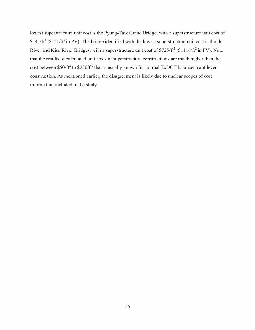
55
lowest superstructure unit cost is the Pyung-Taik Grand Bridge, with a superstructure unit cost of
$141/ft2 ($121/ft2 in PV). The bridge identified with the lowest superstructure unit cost is the Ibi
River and Kiso River Bridges, with a superstructure unit cost of $725/ft2 ($1116/ft2 in PV). Note
that the results of calculated unit costs of superstructure constructions are much higher than the
cost between $50/ft2 to $250/ft2 that is usually known for normal TxDOT balanced cantilever
construction. As mentioned earlier, the disagreement is likely due to unclear scopes of cost
information included in the study.

56
12
10
17
65
21% 18% 30% 11% 9%0
2
4
6
8
10
12
14
16
18
0‐199.9 200‐399.9 400‐599.9 600‐799.9 800‐999.9
Count (%
out of 57)
Unit Cost Total, $/ft2
11 11
13
3
7
19% 19% 23% 5% 12%0
2
4
6
8
10
12
14
0‐199.9 200‐399.9 400‐599.9 600‐799.9 800‐999.9
Count (%
out of 57)
Unit Cost Total PV, $/ft2
(a). Cost at Project Completion (within 0 to 1000$/ft2 Range) (b). Cost at PV (within 0 to 1000$/ft2 Range)
50
2 2 1 288% 4% 4% 2% 4%0
10
20
30
40
50
60
Count (%
out of 57)
Unit Cost Total, $/ft2
45
7
2 2 179% 12% 4% 4% 2%0
5
10
15
20
25
30
35
40
45
50
Count (%
out of 57)
Unit Cost Total PV, $/ft2
(c). Cost at Project Completion (d). Cost at PV
Figure 42. Distribution of Unit Cost.

57
2 2
1
3
25% 25%13%
38%
0
0.5
1
1.5
2
2.5
3
3.5
0‐199.9 200‐399.9 400‐599.9 600‐799.9 800‐999.9 1000‐1199.9
Count (%
out of 8)
Unit Cost Superstructure , $/ft2
(a) Cost at Project Completion
2
1 1 1
2
29%14% 14% 14%
29%
0
0.5
1
1.5
2
2.5
0‐199.9 200‐399.9 400‐599.9 600‐799.9 800‐999.9 1000‐1199.9
Count (%
out of 8)
Unit Cost Superstructure PV , $/ft2
(b). Cost at PV
Figure 43. Distribution of Unit Cost of Superstructure.
A statistical analysis was performed based on the cost information collected; the results
are summarized in Table 9. As shown in Table 7 and Table 8, the cost information collected in
the study is highly variable and might not be appropriate to provide baseline information
regarding cost of a normal extradosed bridge construction. There is a small number of bridges,
including the Kyong-An Bridge and the New Pearl Harbor Memorial Bridge, that show
significantly higher costs comparing to other bridges. The significant difference might lead to a
distortion of cost analysis. Adjusted average values were therefore calculated by excluding
outliers, i.e., values outside of average values plus or minus one standard deviation.
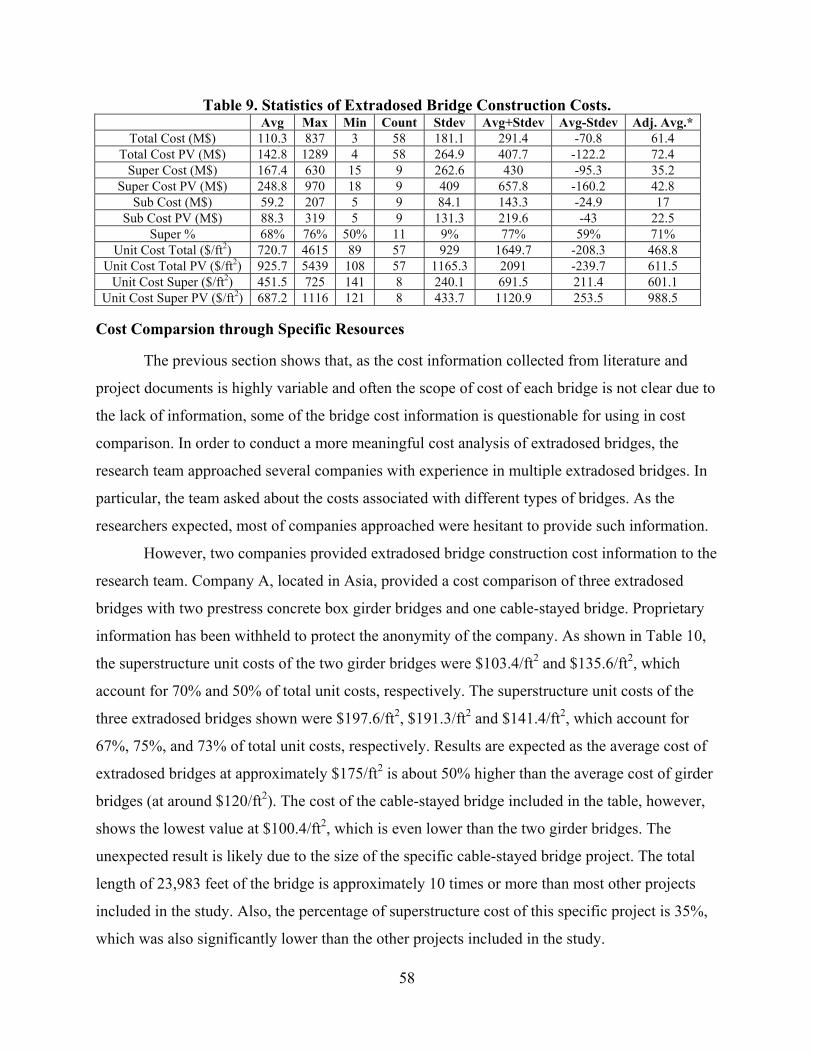
58
Table 9. Statistics of Extradosed Bridge Construction Costs. Avg Max Min Count Stdev Avg+Stdev Avg-Stdev Adj. Avg.*
Total Cost (M$) 110.3 837 3 58 181.1 291.4 -70.8 61.4 Total Cost PV (M$) 142.8 1289 4 58 264.9 407.7 -122.2 72.4
Super Cost (M$) 167.4 630 15 9 262.6 430 -95.3 35.2 Super Cost PV (M$) 248.8 970 18 9 409 657.8 -160.2 42.8
Sub Cost (M$) 59.2 207 5 9 84.1 143.3 -24.9 17 Sub Cost PV (M$) 88.3 319 5 9 131.3 219.6 -43 22.5
Super % 68% 76% 50% 11 9% 77% 59% 71% Unit Cost Total ($/ft2) 720.7 4615 89 57 929 1649.7 -208.3 468.8
Unit Cost Total PV ($/ft2) 925.7 5439 108 57 1165.3 2091 -239.7 611.5 Unit Cost Super ($/ft2) 451.5 725 141 8 240.1 691.5 211.4 601.1
Unit Cost Super PV ($/ft2) 687.2 1116 121 8 433.7 1120.9 253.5 988.5
Cost Comparsion through Specific Resources
The previous section shows that, as the cost information collected from literature and
project documents is highly variable and often the scope of cost of each bridge is not clear due to
the lack of information, some of the bridge cost information is questionable for using in cost
comparison. In order to conduct a more meaningful cost analysis of extradosed bridges, the
research team approached several companies with experience in multiple extradosed bridges. In
particular, the team asked about the costs associated with different types of bridges. As the
researchers expected, most of companies approached were hesitant to provide such information.
However, two companies provided extradosed bridge construction cost information to the
research team. Company A, located in Asia, provided a cost comparison of three extradosed
bridges with two prestress concrete box girder bridges and one cable-stayed bridge. Proprietary
information has been withheld to protect the anonymity of the company. As shown in Table 10,
the superstructure unit costs of the two girder bridges were $103.4/ft2 and $135.6/ft2, which
account for 70% and 50% of total unit costs, respectively. The superstructure unit costs of the
three extradosed bridges shown were $197.6/ft2, $191.3/ft2 and $141.4/ft2, which account for
67%, 75%, and 73% of total unit costs, respectively. Results are expected as the average cost of
extradosed bridges at approximately $175/ft2 is about 50% higher than the average cost of girder
bridges (at around $120/ft2). The cost of the cable-stayed bridge included in the table, however,
shows the lowest value at $100.4/ft2, which is even lower than the two girder bridges. The
unexpected result is likely due to the size of the specific cable-stayed bridge project. The total
length of 23,983 feet of the bridge is approximately 10 times or more than most other projects
included in the study. Also, the percentage of superstructure cost of this specific project is 35%,
which was also significantly lower than the other projects included in the study.
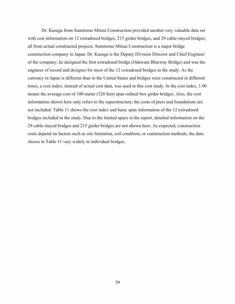
59
Dr. Kasuga from Sumitomo Mitsui Construction provided another very valuable data set
with cost information on 12 extradosed bridges, 215 girder bridges, and 29 cable-stayed bridges;
all from actual constructed projects. Sumitomo Mitsui Construction is a major bridge
construction company in Japan. Dr. Kasuga is the Deputy Division Director and Chief Engineer
of the company; he designed the first extradosed bridge (Odawara Blueway Bridge) and was the
engineer of record and designer for most of the 12 extradosed bridges in the study. As the
currency in Japan is different than in the United States and bridges were constructed in different
times, a cost index, instead of actual cost data, was used in this cost study. In the cost index, 1.00
means the average cost of 100-meter (328 feet) span ordinal box girder bridges. Also, the cost
information shown here only refers to the superstructure; the costs of piers and foundations are
not included. Table 11 shows the cost index and basic span information of the 12 extradosed
bridges included in the study. Due to the limited space in the report, detailed information on the
29 cable-stayed bridges and 215 girder bridges are not shown here. As expected, construction
costs depend on factors such as site limitation, soil condition, or construction methods; the data
shown in Table 11 vary widely in individual bridges.
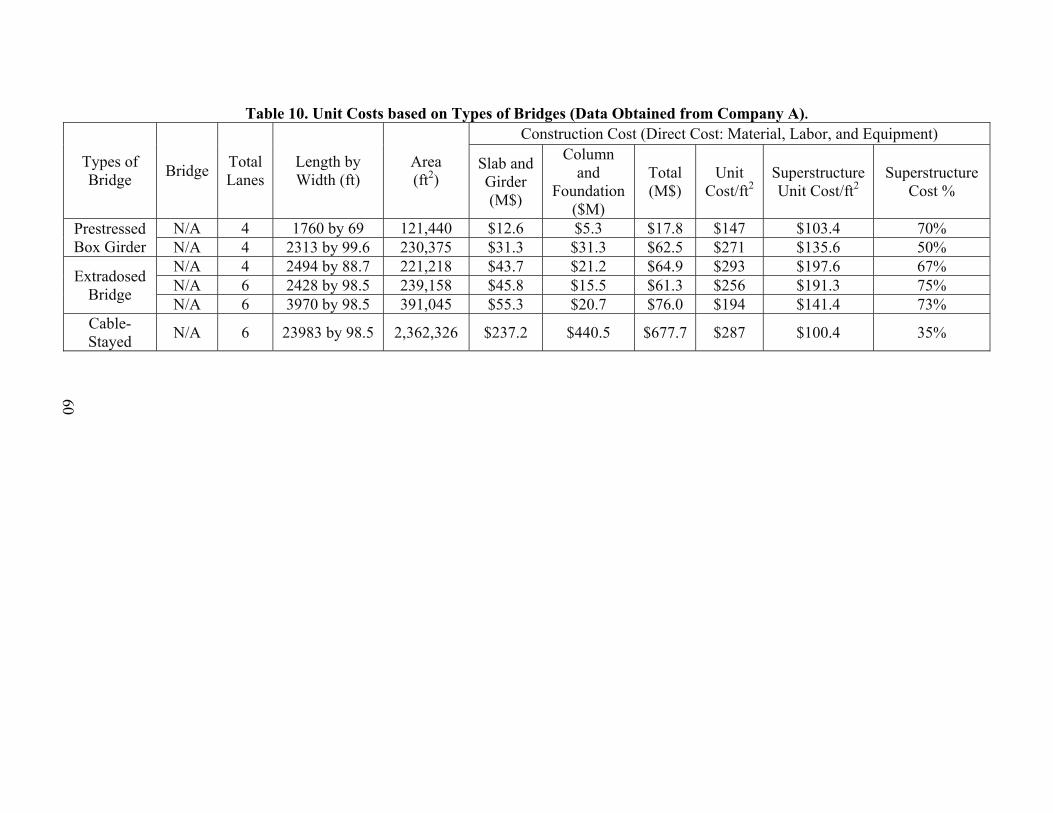
60
Table 10. Unit Costs based on Types of Bridges (Data Obtained from Company A).
Types of Bridge Bridge Total
Lanes Length by Width (ft)
Area (ft2)
Construction Cost (Direct Cost: Material, Labor, and Equipment)
Slab and Girder (M$)
Column and
Foundation ($M)
Total (M$)
Unit Cost/ft2
Superstructure Unit Cost/ft2
Superstructure Cost %
Prestressed Box Girder
N/A 4 1760 by 69 121,440 $12.6 $5.3 $17.8 $147 $103.4 70% N/A 4 2313 by 99.6 230,375 $31.3 $31.3 $62.5 $271 $135.6 50%
Extradosed Bridge
N/A 4 2494 by 88.7 221,218 $43.7 $21.2 $64.9 $293 $197.6 67% N/A 6 2428 by 98.5 239,158 $45.8 $15.5 $61.3 $256 $191.3 75% N/A 6 3970 by 98.5 391,045 $55.3 $20.7 $76.0 $194 $141.4 73%
Cable-Stayed N/A 6 23983 by 98.5 2,362,326 $237.2 $440.5 $677.7 $287 $100.4 35%

61
Table 11. Cost Index of Different Extradosed Bridges (Data Obtained from Sumitomo Mitsui Construction).
Bridge Name Year Structure Type Number of Span
Total Length (ft)
Road Width (ft)
Main Span Length (ft)
*Equivalent Length of Main
Span
Cost Index
Odawara Blueway Bridge 1994 rigid frame 3 886 31 400 400 1.00
Tsukuhara Bridge 1998 rigid frame 3 1,060 30 591 591 1.64
Ibi Bridge 2002 Continuous (composite ) 6 4,583 92 891 891 2.23
Hozu Bridge 2001 rigid frame 3 1,207 48 328 328 1.05 Tobiuo Bridge 2003 continuous 3 1,266 82 427 427 1.11
Akatonobo Bridge 2004 rigid frame 3 965 52 401 401 1.51 Arakogawa Bridge 2004 rigid frame 3 807 30 295 295 1.09 Tatekoshi Bridge 2004 rigid frame 2 371 51 185 370 1.34 Yanagawa Bridge 2006 rigid frame 2 866 46 430 860 1.81 Nanchiku Bridge 2006 rigid frame 3 814 50 361 361 1.26 Satonojyo Bridge 2006 rigid frame 3 610 49 253 253 1.05
Asagiri Bridge 2006 rigid frame 2 545 49 279 558 1.08 *Equivalent length of main span: Equivalent length = 2.0 × maximum length for a 2-span structure

62
Figure 44 shows the relationship between main span lengths and cost indices of the
three different types of bridges. The figure shows that although there is no clear trend in the costs
of the three different types of bridges observed, generally speaking, extradosed bridges are more
economical than cable-stayed bridges. Also, even though the cost of cable-stayed bridges could
be significantly higher, this is not necessarily higher than traditional girder bridges. Even though
cost indices are highly variable, compared to girder bridges, especially within 500 feet of the
main span length, extradosed bridges could be a cost-effective option. As shown in Figure 44, at
the span length ranging from 300 to 800 feet, an extradosed bridge could be a competitive bridge
form compared to a cable-stayed bridge.
y = 0.0004x + 0.9577R² = 0.0263
y = 0.0018x + 0.545R² = 0.7844
y = 0.0005x + 1.5441R² = 0.028
0.0
0.5
1.0
1.5
2.0
2.5
3.0
0 200 400 600 800 1000 1200
Co
st in
dex
Main span length, ft
Girder BridgeExtradosed BridgeCable-stayed BridgeLinear (Girder Bridge)Linear (Extradosed Bridge)Linear (Cable-stayed Bridge)
Figure 44. Cost Index of Different Types of Bridges from Sumitomo Mitsui Construction.
Note that even though construction costs of bridges are highly dependable on site
conditions, the cost of bridges constructed by a same company, likely with the same setup and
crews, should provide a more reliable comparison. Therefore, compared to construction costs
from different sources collected through literature review and interviews, cost information
collected from the two abovementioned specific companies is considered to be more
representative.

63
An extradosed bridge generally requires a comparable amount of prestressing as a girder
bridge, but a reduced quantity of concrete. If the cost of towers is excluded, the superstructure
cost of an extradosed bridge can be on a par with or less than that of a girder bridge. Since
concrete accounts for a significant portion of the superstructure cost, the extradosed bridge could
be at an advantage in the total material cost. Due to the reduced superstructure weight and the
resulting potential reduced cost of the substructure, the overall cost of an extradosed bridge
construction might not necessarily be higher than that of a girder bridge and therefore could be a
more cost-effective alternative.
SUMMARY
While construction of extradosed bridges spread out in different countries and different
times, and each bridge was constructed under different site conditions, construction costs
collected from this study were found to be highly variable Cost information collected from
selected companies with experience in building girder bridges, extradosed bridges, and cable-
stay bridges showed that extradosed bridges are generally found to be less expensive than cable-
stayed bridges. The information also showed that extradosed bridges could be at an advantage to
prestressed girder bridges in total material costs due to the reduced quantities of concrete because
of the use of extradosed cables. In addition, considering the reduced superstructure weight and
potential reduced substructure cost, the overall cost of extradosed bridges is not necessary higher
than girder bridges.

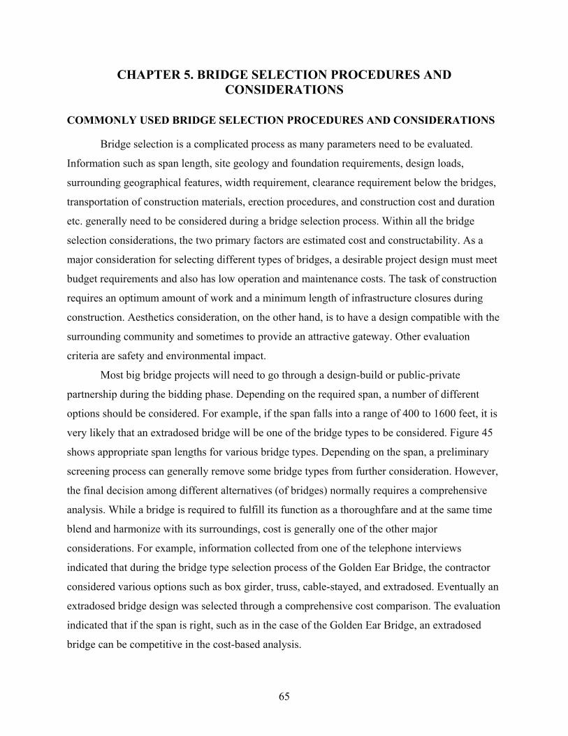
65
CHAPTER 5. BRIDGE SELECTION PROCEDURES AND CONSIDERATIONS
COMMONLY USED BRIDGE SELECTION PROCEDURES AND CONSIDERATIONS
Bridge selection is a complicated process as many parameters need to be evaluated.
Information such as span length, site geology and foundation requirements, design loads,
surrounding geographical features, width requirement, clearance requirement below the bridges,
transportation of construction materials, erection procedures, and construction cost and duration
etc. generally need to be considered during a bridge selection process. Within all the bridge
selection considerations, the two primary factors are estimated cost and constructability. As a
major consideration for selecting different types of bridges, a desirable project design must meet
budget requirements and also has low operation and maintenance costs. The task of construction
requires an optimum amount of work and a minimum length of infrastructure closures during
construction. Aesthetics consideration, on the other hand, is to have a design compatible with the
surrounding community and sometimes to provide an attractive gateway. Other evaluation
criteria are safety and environmental impact.
Most big bridge projects will need to go through a design-build or public-private
partnership during the bidding phase. Depending on the required span, a number of different
options should be considered. For example, if the span falls into a range of 400 to 1600 feet, it is
very likely that an extradosed bridge will be one of the bridge types to be considered. Figure 45
shows appropriate span lengths for various bridge types. Depending on the span, a preliminary
screening process can generally remove some bridge types from further consideration. However,
the final decision among different alternatives (of bridges) normally requires a comprehensive
analysis. While a bridge is required to fulfill its function as a thoroughfare and at the same time
blend and harmonize with its surroundings, cost is generally one of the other major
considerations. For example, information collected from one of the telephone interviews
indicated that during the bridge type selection process of the Golden Ear Bridge, the contractor
considered various options such as box girder, truss, cable-stayed, and extradosed. Eventually an
extradosed bridge design was selected through a comprehensive cost comparison. The evaluation
indicated that if the span is right, such as in the case of the Golden Ear Bridge, an extradosed
bridge can be competitive in the cost-based analysis.

66
0 1000 2000 3000 4000 5000 6000 7000 8000 9000
Girder
Truss
Arch
Extradosed
Cable‐stayed
Suspension
Span Length Range (feet)
Bridge Type
Figure 45. Span Ranges for Different Types of Bridges.
Beside the abovementioned considerations, the methods for cost-effectiveness analyses
including Life Cycle Cost Analysis, Value Engineering (VE), and criteria-based bridge selection
procedures that can be used for general bridge selection are summarized below.
Life Cycle Cost Analysis (LCCA)
Bridge construction involves fabrication and erection operations needed for safe and
efficient building of the structures in accordance with the construction documents. Bridge
maintenance, on the other hand, involves ensuring public safety, i.e., to reduce life cycle costs
and earn public confidence. As shown in Chapter 4, an extradosed bridge will probably initially
cost more than a conventional girder bridge, yet would cost less than a cable-stayed bridge of the
same length. However, an extradosed bridge is also expected to be less expensive to maintain
over a longer term basis, compared to a cable-stayed bridge. Therefore, it is important to
examine the overall cost-effectiveness of extradosed bridges over other types of bridges. LCCA
is a process for evaluating the total economic cost of an asset by analyzing initial costs and

67
discounted future expenditures, such as operation, maintenance, and repair (O, M&R) costs, and
user and social costs over the service life of the asset.
While a bridge with a longer service life is generally preferable, the maintenance fee
increases along with the time or use of a bridge. The LCCA methodology has some important
characteristics that allow composites to be evaluated on an equal basis with existing construction
materials. The method is project-based, which means that materials are compared based on costs to
build typical structures, instead of measures such as “dollars per pound of material.” Costs of
constructing and demolishing bridges can be obtained from the engineer who designed the bridge,
and the general contractor who was awarded the bridge contract. Operation, maintenance, and
repair figures can be obtained from maintenance officials. All agency costs involved in each
alternative over the planning period are factored into the LCCA, potentially including the costs of
design, construction, contingency and administration, right-of-way, inspection and routine
maintenance, painting and repair, rehabilitation and strengthening, girder widening, complete
bridge demolition and replacement. The concept of LCCA used in infrastructure is not new for
TxDOT, as an LCCA program has been developed through TxDOT Projects 0-1734 and 0-1739
(Beg et al. 1998; Waalkes 1999). TxDOT is currently considering LCCA for selecting pavement
alternates, i.e., rigid versus flexible pavement (Wimsatt et al. 2009).
A procedure for bridge alternatives selection could be established based on previous
researches of bridge LCCA. Parameters—such as bridge span, width, depth of the valley or
seabed—should be considered as factors of influence on bridge LCCA. An example of the
process and basic steps of a BLCCA program, NCHRP’s Bridge Life-Cycle Cost Analysis
(Hawk 2003) is illustrated in Figure 46.

68
Figure 46. BLCCA Process (adapted from Hawk 2003).
A prototype of a bridge selection matrix based on LCCA can be developed accordingly.
An example of a developed prototype is shown in Table 12, in which the bolded number
indicates the optimum alternative based on LCCA.
Table 12. Prototype of Bridge Selection Matrix Based on LCCA with Dummy Data. Alternative A
(Girder)Alternative B (Extradosed)
Alternative C (Cable-stayed)
Construction Costs Design Costs $3,000 $6,000 $10,000 Construction Costs $80,000 $100,000 $150,000
O, M, & R Costs Operation $10,000 $10,000 $10,000 Maintenance $5,000 $2,000 $3,000
Repair $30,000 $5,000 $0 Salvage Value Salvage Value $0 $2,000 $5,000
Life Cycle Cost $128,000 $121,000 $168,000 Note: All data here have been converted into Net Present Value (NPV)

69
It should be pointed out that the analysis of LCC is often challenging as some cost data
are hard to collect; it is also difficult to provide a precise prediction of the service life of an
infrastructure. While the NCHRP synthesis 483 (Bridge Life-Cycle Cost Analysis) indicated that
LCCA can be a promising tool in bridge selection base on cost-effectiveness, the application of
the LCCA concept in bridges is still very limited. Issues such as target reliability level,
whole-life performance assessment rules, and optimum inspection-repair-replacement strategies
for bridges must be analyzed and resolved from a life-cycle cost perspective. Cost estimates will
probably be preliminary in nature and based primarily on historical cost data from other relevant
structures. As it is difficult to completely predict the service life of an infrastructure asset, it is
equally difficult to anticipate or forecast its LCC.
At present, only selected state departments of transportation are considering life-cycle
cost methodologies and software with the goal of developing a standard method for assessing the
cost-effectiveness of concrete bridges. As most of extradosed bridges are relatively new, it is
expected that maintenance costs or estimation might not be available from contractors and
agencies. Models and simulations are therefore needed to predict maintenance and repairing
costs, which will inevitably further increase the difficulty in LCCA. While TxDOT is still not
practically ready to adopt the LCCA concept in the bridge selection process, it clearly recognized
the advantages of LCCA in the decision-making process. LCCA can be used in TxDOT bridge
selection when necessary information is available in the future.
Value Engineering (VE) and Criteria-Based Bridge Selection Procedures
Bridge management is the decision-making process for selecting and prioritizing the
actions necessary to maintain a bridge within acceptable limits of safety and serviceability.
While the lowest agency cost option may not necessarily be implemented when other
considerations such as aesthetical and cultural value, user cost, and environmental concerns are
taken into account, current decision-making approaches including LCCA normally do not
include indirect impact from the abovementioned considerations. A criteria-based bridge
selection process was therefore developed for deciding on bridge maintenance and bridge type
selection. The difference between criteria-based selection and traditional cost-based selection is
that instead of comparing the exact dollar amounts (costs) that are often difficult to obtain, a
grading (or ranking) system is normally developed so that input from different groups (agencies,

70
engineers, experts, and publics etc.) can be considered and translated into a composite score for
the decision.
Value Engineering (VE) analysis (or multi-attribute ranking method) is another tool that
is commonly used in alternative selection, which covers a broader area compared to an LCCA
(Wilson 2005). VE is a systematic application of recognized analysis techniques normally used
by a multi-disciplined team. The analysis:
Identifies the necessary functions of a product or service.
Establishes a monetary value or worth for that function.
Generates alternatives through the use of creative thinking.
Provides the necessary function reliably, at the lowest life-cycle cost consistent with
performance, maintainability, safety, and aesthetics.
In addition, costs not normally included in traditional LCCA, such as performance,
maintainability, safety, and aesthetics are also to be quantified and taken into account during the
decision-making process. VE may be viewed as a multi-peer review of project recommendations,
and it is designed to gather expertise and experiences of individuals in order to produce the most
effective solution for transportation needs. Since there are different concerns caused by differing
preferences, experiences, and background, a support system is generally required to enable each
stakeholder to evaluate and rank solution alternatives before engaging in negotiation with the
other stakeholders. The support system can be developed based on a combination of value-based
analysis, multicriteria group decision making based on satisfying options, and negotiation
process based on coalition formation. A VE therefore was used for bridge management decision
through balanced consideration of multiple and conflicting criteria involving different decision
makers, such as estate managers, project managers, and engineers (Dabous and Alkass 2008 &
2010; Utomo and Idrus 2010). Different VE programs have already been adapted by some state
agencies in decision making regarding infrastructure management. Table 13 shows an example
of the analysis matrix of decision of three alternatives using VE methods:

71
Table 13. Example of Analysis Matrix using VE Method (adapted from Basha and Gab-Allah 1991).
Evaluation criteria Normalized weight
Alternatives Precast Concrete
Girders Incremental Launching
Prefabricated Steel Construction
Rank Score Rank Score Rank Score Construction cost 24 3.7 88.9 1.7 40.8 1.4 33.6
Maintenance 5 4.0 20.0 3.0 15.0 2.0 10.0 Durability 12 4.0 48.0 4.0 48.0 3.0 36.0 Service life 10 4.0 40.0 4.0 40.0 2.0 20.0
Resource availability 16 3.2 51.2 3.3 52.8 1.0 16.0 Ease of construction 14 3.0 42.0 2.0 28.0 3.0 42.0
Progress rate 12 3.4 40.8 2.6 31.2 4.9 57.6 Design efficiency 7 3.9 27.3 3.0 21.0 4.0 28.0
Total scores - - 358 - 277 - 243 Note: 1. Ranks are excellent = 5; very good = 4, good = 3, fair = 2, and poor = 1; 2. Score = rank × weight
A similar approach called “criteria-based bridge selection” is also used for bridge
maintenance or bridge type decisions. Generally, various categories to be used in this analysis
will be identified based on literature review, construction documents, collection of public
opinions, and feedback from bridge engineers. A survey can be used to obtain input on the
various bridge types being considered to determine weights of each category and scores from
each alternative. During the bridge selection process, a set of design guidelines that represent
aesthetic, environmental and context sensitive considerations is developed first. Alternatives are
then to be developed based on public inputs, together with engineering, context, constructability
assessments, and budgets. In order to select the appropriate bridge type, the public can also be
polled on the degree of importance that should be given over different categories such as
aesthetics, construction costs, maintenance, and construction impacts. Table 14 presents an
example of a criteria-based bridge selection matrix that can be used for bridge selection between
extradosed bridges, concrete, and steel girder bridges.
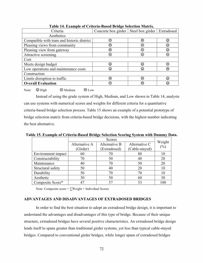
72
Table 14. Example of Criteria-Based Bridge Selection Matrix. Criteria Concrete box girder Steel box girder Extradosed
Aesthetics Compatible with tram and historic district Pleasing views from community Pleasing view from gateway Attractive screening Cost Meets design budget Low operations and maintenance costs Construction Limits disruption to traffic Overall Evaluation
Note: High Medium Low
Instead of using the grade system of High, Medium, and Low shown in Table 14, analysts
can use systems with numerical scores and weights for different criteria for a quantitative
criteria-based bridge selection process. Table 15 shows an example of a potential prototype of
bridge selection matrix from criteria-based bridge decisions, with the highest number indicating
the best alternative.
Table 15. Example of Criteria-Based Bridge Selection Scoring System with Dummy Data. Scores Weight
(%) Alternative A (Girder)
Alternative B (Extradosed)
Alternative C (Cable-stayed)
Environment impact 60 70 80 10 Constructability 70 50 40 20 Maintenance 40 70 50 20 Structural safety 50 40 20 10 Durability 50 70 70 10 Aesthetic 30 50 60 30 Composite Score* 47 57 53 100
Note: Composite score = ∑Weight × Individual Scores
ADVANTAGES AND DISADVANTAGES OF EXTRADOSED BRIDGES
In order to find the best situation to adopt an extradosed bridge design, it is important to
understand the advantages and disadvantages of this type of bridge. Because of their unique
structure, extradosed bridges have several positive characteristics. An extradosed bridge design
lends itself to spans greater than traditional girder systems, yet less than typical cable-stayed
bridges. Compared to conventional girder bridges, while longer spans of extradosed bridges
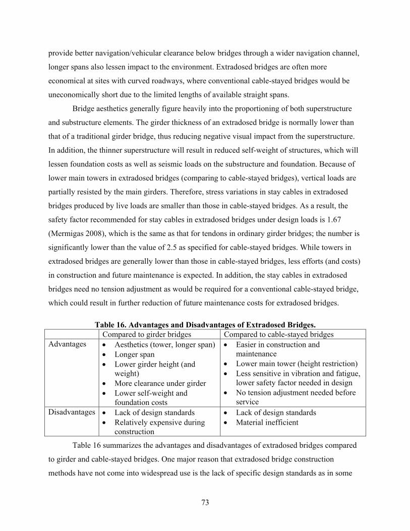
73
provide better navigation/vehicular clearance below bridges through a wider navigation channel,
longer spans also lessen impact to the environment. Extradosed bridges are often more
economical at sites with curved roadways, where conventional cable-stayed bridges would be
uneconomically short due to the limited lengths of available straight spans.
Bridge aesthetics generally figure heavily into the proportioning of both superstructure
and substructure elements. The girder thickness of an extradosed bridge is normally lower than
that of a traditional girder bridge, thus reducing negative visual impact from the superstructure.
In addition, the thinner superstructure will result in reduced self-weight of structures, which will
lessen foundation costs as well as seismic loads on the substructure and foundation. Because of
lower main towers in extradosed bridges (comparing to cable-stayed bridges), vertical loads are
partially resisted by the main girders. Therefore, stress variations in stay cables in extradosed
bridges produced by live loads are smaller than those in cable-stayed bridges. As a result, the
safety factor recommended for stay cables in extradosed bridges under design loads is 1.67
(Mermigas 2008), which is the same as that for tendons in ordinary girder bridges; the number is
significantly lower than the value of 2.5 as specified for cable-stayed bridges. While towers in
extradosed bridges are generally lower than those in cable-stayed bridges, less efforts (and costs)
in construction and future maintenance is expected. In addition, the stay cables in extradosed
bridges need no tension adjustment as would be required for a conventional cable-stayed bridge,
which could result in further reduction of future maintenance costs for extradosed bridges.
Table 16. Advantages and Disadvantages of Extradosed Bridges. Compared to girder bridges Compared to cable-stayed bridges Advantages Aesthetics (tower, longer span)
Longer span Lower girder height (and
weight) More clearance under girder Lower self-weight and
foundation costs
Easier in construction and maintenance
Lower main tower (height restriction) Less sensitive in vibration and fatigue,
lower safety factor needed in design No tension adjustment needed before
service Disadvantages Lack of design standards
Relatively expensive during construction
Lack of design standards Material inefficient
Table 16 summarizes the advantages and disadvantages of extradosed bridges compared
to girder and cable-stayed bridges. One major reason that extradosed bridge construction
methods have not come into widespread use is the lack of specific design standards as in some

74
countries. As mentioned in Chapter 2, with the exception of Japan, there is no widely accepted
design rule and/or code that provide design standards for extradosed bridges. The reference is
available only in Japanese language. It is often challenging to revise the design of an extradosed
bridge so it will conform to the local design code, owing to regulations specifying that the
external cable system must not be placed on the outside of the girders. On the other hand, given
the extradosed bridge’s intermediate design, it is often considered as relatively expensive
(compared to girder bridges) and material inefficient (compared to cable-stayed bridges). In
many cases, the spans of extradosed bridges are short enough that the use of cables is more for
aesthetic purposes rather than as an engineering-necessitated choice. However, this does not
necessarily mean it is a bad choice; the extradosed bridge type is a very elegant form especially
when the difference in cost and efficiency is small.
MAJOR REASONS FOR SELECTING EXTRADOSED BRIDGES
Through literature and interviews, bridge selection reasons for a total of 47 extradosed
bridges were identified and summarized in Table 17. As shown in the table, major reasons in
which extradosed bridges were selected include:
Aesthetic consideration (signature bridge).
Structure and construction consideration (proper span lengths, unique site conditions, and
seismic consideration).
Underneath (navigation/vehicular/hydraulic) clearance and height (aviation) restriction.
Economic, together with compatibility and environmental considerations.

75
Table 17. Extradosed Bridge Selection Reasons. Bridge Name Reasons Reference
1 Odawara Blueway Bridge Lower cost, landmark structure, underneath clearance, height restriction Mermigas 2008, Kasuga 2012, Stroh 2012
2 Tsukuhara Bridge Economic, aesthetic, fit with adjacent CS pedestrian bridge Mermigas 2008, Kasuga 2012 5 Shin-Karato (Okuyama) Bridge Shallow depth girder spans over unstable slope Mermigas 2008
6 Sunniberg Bridge Sensitive landscape, justified the increased cost, least visual impact on the idyllic Alpine view. Tall piers, emphasis on aesthetics Mermigas 2008; Drinkwater, 2007
9 Second Mactan–Mandaue Bridge Height restriction from airport Mermigas 2008
10 Pont de Saint-Rémy-de-Maurienne Bridge Shallow clearance over highway underneath Stroh 2012
12 Pakse Bridge Long navigational span of long viaduct Mermigas 2008 16 Wuhu Yangtze River Bridge Navigation clearance, aviation restriction, proper span for navigation Fang 2002
19 Ibi River Bridge (Ibigawa Bridge) Economic, aesthetic, heavy prefabrication. Lightweight design, shortened construction period, design against fatigue for the stays.
Mermigas 2008, Kasuga 2012; Ikeda and Kasuga 2010
20 Kiso River Bridge (Kisogawa Bridge)
Economic, aesthetic, heavy prefabrication. Lightweight design, shortened construction period, design against fatigue for the stays.
Mermigas 2008, Kasuga 2012; Ikeda and Kasuga 2010
21 Miyakoda River Bridge (Miyakodagawa Bridge) Landmark structure with good seismic resistance Mermigas 2008
23 Zhangzhou Zhanbei Bridge Fit adjacent buildings, proper span for navigation, aesthetic, shorten construction period, relative low cost, use of unique site condition
(island in the river) Tang et al. 2002,
25 Koror-Babeldaob (Japan-Palau Friendship) Bridge Navigational clearance, height restriction from airport Mermigas 2008
27 Shinkawa (Tobiuo) Bridge Clearance under bridge Mermigas 2008 28 Tongan Yinhu Bridge Aesthetic Li and Zeng, 2002
30 Deba River Bridge Compactable with surrounding landscape, shallow clearance over highway underneath
Llombart and Revoltos 2004, Mermigas 2008
31 Xiaoxihu Yellow River Bridge Navigation clearance, aesthetic, height restriction, anti-sedimentation Zhang and Kang 2002
39 Shuqian Nanerhuan Bridge Seismic resistance for earthquake, navigation clearance, aesthetic, signature bridge, shorten construction time Zhang 2004
41 Sannohe–Boukyo Bridge Span of 200 meters to cross protected river and train line Mermigas 2008 42 Lishi Gaojia Bridge Aesthetic, low cost, minimum span of 120 meters He 2004a, He 2004b
45 Ritto (Rittoh) Bridge–Tokyo Bound Gateway structure to reflect the cultural context of Kansai District. Mermigas 2008
48 Liuzhou Sanmenjiang Bridge Navigation clearance, proper span for navigation and flood release Bandu, 2012 55 Fuzhou Pushang Bridge Aesthetic, economic compared to cable-stayed bridges Eemap, 2012 57 Homeland (Domovinski) Bridge Long span of viaduct to cross the river Mermigas 2008

76
Bridge Name Reasons Reference
61 Ailan Bridge Signature bridge, aesthetic, long span to reduce number of piers, least environment impact Ko 2008
62 Nymburk Bypass Bridge Navigation clearance, appropriate span Lusas.com, 2012
63 Puh (Puhov) Bridge
Preserve views of historical heritage, large span, thin structure, and severe restrictions on support layout, low bridge elevation and requested
waterway and shipping clearance, road geometry in a sharp curvature (not allowing longer spans).
Slovenia Chapter of Engineers 2012, Makelj 2010; Makelj 2012
65 Smuuli Bridge Impossible to put scaffolding or pier in the middle of roadway part station Saar 2012
67 Second Vivekananda Bridge Comparable to the temple on the Calcutta side, navigation clearance, height less than nearby temple Mermigas 2008; Binns 2005
74 North Arm Bridge Navigation clearance, height restriction from airport, seismic consideration to decrease superstructure weight Mermigas 2008; Scollard 2012
76 Trois-Bassins Viaduct Bridge Tall piers, access from one side of gorge only, harmonious to the environment
Stroh 2012; Mermigas 2008; Charlon and Frappart 2008
79 Golden Ears Bridge Navigation clearance, height restriction from airport, seismic consideration to decrease superstructure weight Mermigas 2008; Scollard 2012
80 Karnaphuli III Bridge Geographical uniqueness, possible impact of siltation Finical Express, 2012 82 Husong Bridge Aesthetic and compatible with the river 163.com 2012 86 Choqueyapu Bridge Signature bridge Sobrino 2011
89 Povazska Bystrica D1 Motorway Viaduct Signature bridge Strasky 2012
90 Teror Viaduct The grandeur of the landscape and dimensions of the valley require a structure to provide great clearance Skyscrapercity.com 2012
95 Jiayue (Nanping) Bridge Navigation clearance, aesthetic Baidu.com 2012 96 Tisza Bridge Proper span and navigation clearance in flood area Matyassy 2010
99 Guemgang I Bridge Construction method, environment, cost, aesthetic. Does not overshadow its neighbor. Choi 2012, BD&E 2008
103 Najin Bridge Aesthetic, low maintenance, compatible to nearby buildings cctv.com 2012, qikan.com.cn 2012
107 New Pearl Harbor Memorial (Quinnipiac) Bridge
Aviation limitation, navigation clearance, desired span length, reasonable cost, signature bridge Stroh 2012
109 Ningjiang Shonghuajiang Bridge Proper span for navigation and flood, navigation clearance, compatible to environment, aesthetic Liu et al. 2010
113 Saint Croix River Bridge Signature bridge, geometric, and physical restriction Strasky 2012 115 Brazos River Bridge Aesthetics requirement Finley 2012
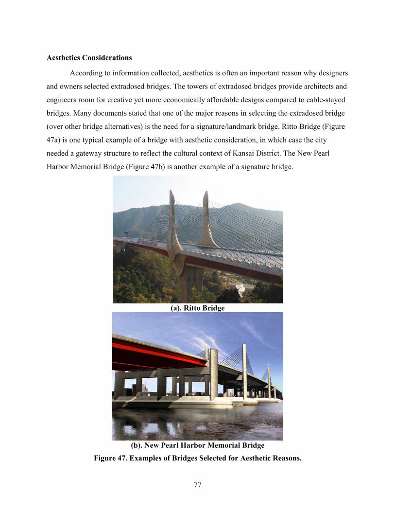
77
Aesthetics Considerations
According to information collected, aesthetics is often an important reason why designers
and owners selected extradosed bridges. The towers of extradosed bridges provide architects and
engineers room for creative yet more economically affordable designs compared to cable-stayed
bridges. Many documents stated that one of the major reasons in selecting the extradosed bridge
(over other bridge alternatives) is the need for a signature/landmark bridge. Ritto Bridge (Figure
47a) is one typical example of a bridge with aesthetic consideration, in which case the city
needed a gateway structure to reflect the cultural context of Kansai District. The New Pearl
Harbor Memorial Bridge (Figure 47b) is another example of a signature bridge.
(a). Ritto Bridge
(b). New Pearl Harbor Memorial Bridge
Figure 47. Examples of Bridges Selected for Aesthetic Reasons.

78
Economic Considerations
As stated in Chapter 4, initial construction cost is one of the major considerations in
bridge selection. Generally, initial and future maintenance costs of extradosed bridges are
considered to be higher than that of girder bridges and lower than that of cable-stayed bridges.
Compared to the prestressed girder bridge, the extradosed bridge design could be at an advantage
in total materials costs due to the reduced quantity of concrete. In addition, considering the
reduced superstructure weight and potential reduced substructure cost, overall costs of
extradosed bridges are not necessarily higher than girder bridges. According to the survey from
the research team, economics is one of the major reasons that extradosed bridges were selected
over other alternatives.
Height Restriction and Clearance
Comparing to cable-stayed bridges, extradosed bridges have shorter towers. The tower
height of an extradosed bridge is usually around one-eighth of the main span length. In contrast,
the tower height of a cable-stayed bridge is usually around one-fifth of the main span. For
example, the two extradosed bridges built in Canada, North Arm Bridge (Figure 5) and Golden
Ears Bridge; are adjacent to the Vancouver Airport. In order to provide a sufficient glide
clearance for the airplanes, the heights of the towers are closely restricted. The height restriction
therefore resulted in the selection of extradosed bridges over traditional cable-stayed bridges.
Figure 48. Example of Consideration of Aviation Restriction (North Arm Bridge).

79
Besides aviation restriction, some other bridges also have restrctions for different
considerations. One example is the Second Vivekananda Bridge (Figure 49) constructed in India,
where the bridge towers were required to be lower than the nearby temple and comparable to
adjacent structures.
Figure 49. Example of Height Restriction to Fit Adjacent Structures (Second Vivekananda
Bridge).
Compared to girder bridges, extradosed bridges generally have shallow structures. Girder
thicknesses of extradosed bridges are usually between 6 to 13 feet, which is approximately half
of the girder thicknesses of conventional girder bridges. The shallow structure can provide better
clearance for the underneath traffic, either by land or waterway. The first extradosed bridge, the
Odawara Blueway Bridge (Figure 50) is a good example of bridges requiring navigation
clearance for boat traffic underneath the bridge. An example with a vehicular clearance
requirement is the Pont de Saint-Rémy-de-Maurienne Bridge (Figure 51). The bridge was
constructed above an existing roadway and a river. To avoid building piers in the road or the
river, span lengths were set to be 172 feet and 159 feet, respectively, due to the unique site
location. With the fixed span lengths, a girder bridge design would have much deeper girders
than the extradosed bridge design, which will reduce the clearance underneath the bridge. It was
also not possible to increase the elevation of the bridge or build an arch bridge to provide
underneath clearance in such short spans. As a result, the extradosed bridge was the proper
design in this special case.
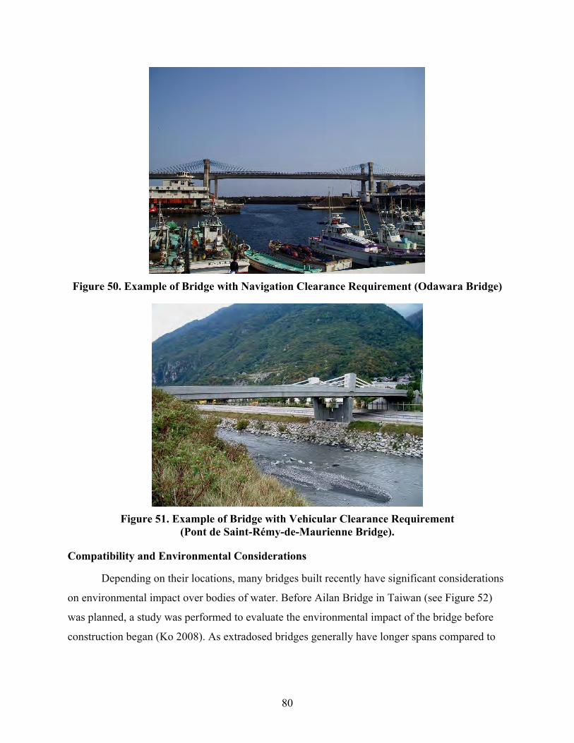
80
Figure 50. Example of Bridge with Navigation Clearance Requirement (Odawara Bridge)
Figure 51. Example of Bridge with Vehicular Clearance Requirement
(Pont de Saint-Rémy-de-Maurienne Bridge).
Compatibility and Environmental Considerations
Depending on their locations, many bridges built recently have significant considerations
on environmental impact over bodies of water. Before Ailan Bridge in Taiwan (see Figure 52)
was planned, a study was performed to evaluate the environmental impact of the bridge before
construction began (Ko 2008). As extradosed bridges generally have longer spans compared to
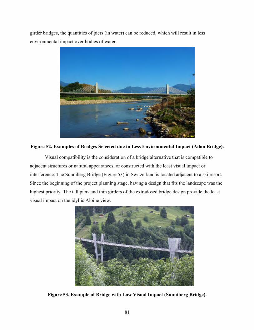
81
girder bridges, the quantities of piers (in water) can be reduced, which will result in less
environmental impact over bodies of water.
Figure 52. Examples of Bridges Selected due to Less Environmental Impact (Ailan Bridge).
Visual compatibility is the consideration of a bridge alternative that is compatible to
adjacent structures or natural appearances, or constructed with the least visual impact or
interference. The Sunniberg Bridge (Figure 53) in Switzerland is located adjacent to a ski resort.
Since the beginning of the project planning stage, having a design that fits the landscape was the
highest priority. The tall piers and thin girders of the extradosed bridge design provide the least
visual impact on the idyllic Alpine view.
Figure 53. Example of Bridge with Low Visual Impact (Sunniberg Bridge).

82
Construction and Structure Considerations
Proper span length is probably one of the most important reasons that extradosed bridges
are selected over other bridge alternatives. An example of long span designs that were used in
crossing deep valleys or rivers is the Trois-Bassins Viaduct in France. As shown in Figure 54,
the bridge crosses a deep ravine. In order to minimize the number of piers, a cable-stayed bridge
design or an extradosed bridge design is preferable. Between the two alternatives, the extradosed
bridge option is more competitive under similar span lengths owing to the lower construction
cost, better constructability, and easier maintenance.
Figure 54. Example of Bridge with Span at Deep Valley (Trois-Bassins Viaduct).
Another reason that extradosed bridges were commonly selected is that these can provide
proper spans for navigation, particularly in flood zones. An example is the Liuzhou Sanmenjiang
Bridge (Figure 55). As the bridge is in a flood zone, the selection of an extradosed bridge design
(over a traditional girder bridge design) can reduce quantities of piers in the water, which not
only provides better a navigation clearance, but also significantly reduces the dangers of
potential impact during flood season.
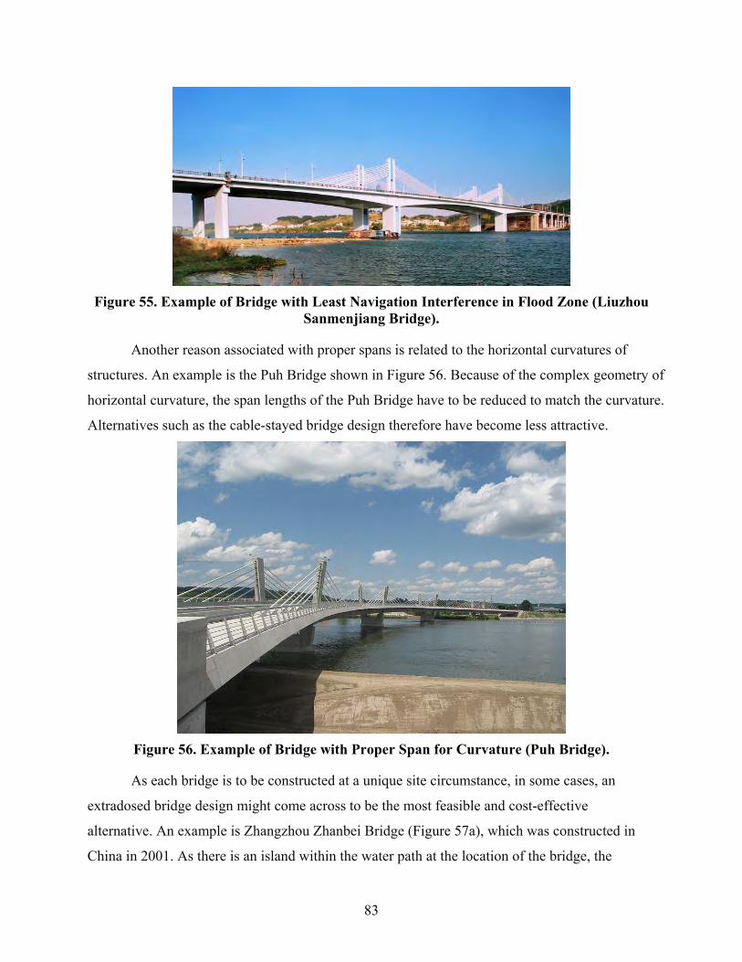
83
Figure 55. Example of Bridge with Least Navigation Interference in Flood Zone (Liuzhou
Sanmenjiang Bridge).
Another reason associated with proper spans is related to the horizontal curvatures of
structures. An example is the Puh Bridge shown in Figure 56. Because of the complex geometry of
horizontal curvature, the span lengths of the Puh Bridge have to be reduced to match the curvature.
Alternatives such as the cable-stayed bridge design therefore have become less attractive.
Figure 56. Example of Bridge with Proper Span for Curvature (Puh Bridge).
As each bridge is to be constructed at a unique site circumstance, in some cases, an
extradosed bridge design might come across to be the most feasible and cost-effective
alternative. An example is Zhangzhou Zhanbei Bridge (Figure 57a), which was constructed in
China in 2001. As there is an island within the water path at the location of the bridge, the

84
extradosed bridge design turned out to be more attractive compared to the alternative of the
concrete-filled steel tube arch bridge. As one of the piers sits right on the island in the river, there
is only one foundation that needs excavation under the water. As a result, construction cost and
duration can be significantly reduced.
Another example of how the extradosed bridge turned out to be an optimum alternative is
the Deba River Bridge (Figure 57b). As one side of the bridge connects to a channel, the bridge
needs to be built in a relatively low altitude in order to meet the elevation of the channel. In
addition, the underneath water traffic passing capacity also needed to be assured. The extradosed
bridge design that has shallow girders eventually turned out to be the ultimate design for this
case (Llombart 2004).
(a).Zhangzhou Zhanbei Bridge
(b). Deba River Bridge
Figure 57. Examples of Bridge in Unique Site Conditions.

85
Construction consideration is one of many other reasons that may lead to decisions of
constructing extradosed bridges. During the construction of the New Pearl Harbor Memorial
Bridge (Figure 58), the design of an extradosed bridge has the advantage of providing
appropriate span lengths through avoiding existing bridge piers, whereas the old bridge can still
be of service during the period of the new bridge construction (CDOT 2012).
Figure 58. Example of Bridge with Construction Consideration (New Pearl Harbor
Memorial Bridge).
Compared to a girder bridge, the extradosed bridge has a shallow structure that also
provides lighter structure weight. In situations where the soil condition cannot support heavy
structures, the extradosed bridge design is preferred. Other seismic considerations, such as
bridges constructed in earthquake zones, also require decreased superstructure weights through
the reduction of girder depth. The better seismic stability was considered one of the benefits of
the final designs of North Arm Bridge and Golden Ears Bridge (Figure 59).

86
Figure 59. Example of Bridge with Structure Consideration (Golden Ears Bridge).
It should be noted that while the reasons for bridge selection listed above might not be
complete or appropriate for other bridge types, some could also be interrelated. For example, an
appropriate span range might reduce the environmental impact through the reduction of
quantities of piers in bodies of water. In most cases, an extradosed bridge was selected as the
ultimate design due to more than one of the reasons mentioned above. In general, there are two
most common situations in which extradosed bridges are better choices than either girder bridges
or cable-stayed bridges. When longer spans and thinner girder depths are needed, the extradosed
type is usually surpassed by the girder bridge type. When a bridge is to be constructed in deep
valleys or rivers, an extradosed bridge is generally a better choice compared to a cable-stayed
bridge because of its better constructability, which in turn leads to lower cost. As a hybrid of a
girder bridge and a cable-stayed bridge, the extradosed bridge design provides another option
when neither girder nor cable-stayed bridges is the ultimate choice.
STATISTICS OF BRIDGE SELECTION REASONS
Results showed that while there is a variety of reasons for selecting extradosed bridges
(over other alternatives), the major reasons are:
Aesthetic considerations or needs for signature bridges.

87
Underneath clearance and height restriction.
Compatibility or environmental consideration.
Construction and structure considerations.
Using the identified bridge selection reasons of the 47 extradosed bridges, the researchers
performed a statistic analysis and the results are summarized in Figure 60. The majority (77%) of
bridges have either construction or structure considerations because of the appropriate span
length or unique site conditions. The analysis revealed that 60% of the bridges have
considerations such as height restriction or navigation/vehicular clearance, and that 57% of the
bridges were selected with aesthetic considerations, i.e., the need for a signature bridge or
landmark structure. Also, it noted that 43% of the bridges were selected with compatibility and
environmental considerations, and 21% of the bridges were selected with economic
considerations in mind.
27
10
28
20
36
57% 21% 60% 43% 77%
0
5
10
15
20
25
30
35
40
Aesthetic Eonomic Height Restriction and
Clearance
Compactibility and
Environment
Construction and Structure
Counts (%
out of 47)
Figure 60. Statistics of Considerations in Selecting Extradosed Bridges.
As most of bridges were selected based upon multiple reasons, the percentages shown in
Figure 60 referred to percentages of bridges selected with specific reasons as the only or one of
the considerations. The total percentages in the figure therefore added up to over 100%. Another
approach was adapted by considering partial counts for individual categories. For example, in the
case of Odawara Blueway Bridge, there are four major reasons (economic, aesthetic, clearance,

88
and height restrictions) identified as primary reasons for bridge selection; each of them therefore
counts for 0.25 in the matrix for bridge selection. These adjusted factors were then used and the
distribution of bridge selection reasons is displayed in Figure 61. Similar to the results shown in
Figure 60, the top three reasons for selecting extradosed bridges were aesthetics, construction
and structure, and height restriction and clearance, which account for 28%, 28%, and 24%,
respectively. Only 7% of the bridges are decided by economic reasons, which indicated that most
of the bridges were selected without the cost consideration, or at least not as a primary
consideration.
Aesthetic, 28%
Economic, 7%
Height Restriction and Clearance, 24%
Compactibility and
Environment, 14%
Construction and Structure, 28%
Figure 61. Summary of Bridge Selection Reasons.
CASE STUDIES FOR BRIDGE SELECTION
The selection of a final bridge alternative is typically based upon specific site conditions
and many other considerations. Case studies could therefore serve as a better channel in
analyzing when extradosed bridges should be selected. Four projects were identified and
included as case studies. In addition to project background, information such as bridge
configuration, constructability (site constraints and construction duration), and costs were
collected based on literature review and data collected through surveys and interviews. Case
studies were focused on how and why extradosed bridges were selected (or not selected) in
specified projects. Table 18 lists the cases included in this study.

89
Table 18. List of Cases Included in the Case Studies. Bridge Location Year Built Major Bridge Alternatives
Sunniberg Bridge Switzerland 1998 Truss, girder, extradosed Zhangzhou Zhanbei Bridge China 2001 Extradosed, arch, girder
St. Croix River Crossing U.S. 2014 Extradosed, cable-stayed, girder
Walterdale Bridge Canada 2015 Through-arch bridge, girder, extradosed, cable-stayed
Case #1 Sunniberg Bridge
The Sunniberg Bridge was planned to be constructed in the mid-1970s. However, it did
not happen until a final plan was formulated in 1996, when an extradosed bridge design was
carried out. The main reason for the long planning period is the critical concern to limit the
environmental impact. A proposal for the Sunniberg Bridge construction to cross the Lanquart
Valley and connect to the town of Klosters was carried out in the mid-1970s. However, the initial
design was rejected by the local government due to the environmental concerns (Figi et al. 1997).
In 1993, the government decided to restart this project, and a design competition was conducted.
The extradosed concept design was presented by a Swiss engineer, Christian Menn, and this
design was finally detailed and completed by one of the companies involved in this competition
(Drinkwater 2012).
Aside from the extradosed bridge design, there were four alternative designs. Design (a) is
a six-span composite truss bridge with span lengths of 221.8 feet, 305.0 feet, 305.0 feet, 305.0 feet,
277.2 feet, and 249.5 feet, respectively. Design (b) is a six-span concrete cantilever bridge with
span lengths of 187.0 feet, 341.2 feet, 341.2 feet, 341.2 feet, 341.2 feet, and 178.0 feet,
respectively. Design (c) is a seven-span triangular composite box girder bridge with two 196.9-foot
side spans and five 262.5-foot main spans. Design (d) is a nine-span continuous concrete beam
bridge that contains two 155.8-foot side spans and seven 205.1-foot main spans (Drinkwater
2012). Drawings of the four designs are shown in Figure 62. In this case, the cable-stayed bridge
design was not considered for several reasons. Firstly, a cable-stayed bridge has a higher cost than
an extradosed bridge and a girder bridge. Secondly, the high towers of a cable-stayed bridge may
break the harmony with nature. Lastly, the bridge was to be designed with a curved girder, which
limited the maximum span length, and the cable-stayed bridge designed in this span range does not
have advantages over other bridge types.

90
(a). 6-Span Composite Truss Bridge
(b) 6-Span Concrete Cantilever Bridge
(c). 7-Span Triangular Composite Concrete Box Bridge
(d) 9-Span Continuous Concrete Beam Bridge
Figure 62. Alternative Designs of the Sunniberg Bridge (adapted from Drinkwater 2012).
The extradosed design of the Sunniberg Bridge has five spans with a total length of
1726 feet. The girder has a curved radius 1650 feet at an inclination of 3.2%. Lengths of five
spans are 194 feet, 420 feet, 459 feet, 440 feet, and 213 feet. The girder carries two lanes with a
girder width of 40.6 feet. There are eight short towers with the same height of 48.6 feet (above
the girder surface). The tallest pylon is 203.4 feet high, from the valley floor to the girder
surface. The center span length to tower height ratio is about 9.46:1.
Because the construction site was located near a natural resort and this bridge would be
the only engineering structure in the Lanquart Valley, the local citizens of Klosters requested that
the structure of bridge should be as thin and transparent as possible in order to minimize the
visual impact on the natural view. The unique topography and the requirement to minimize the

91
construction footprint on the ecology, together with characteristics of the extradosed concept,
finally led to this decision to choose an extradosed bridge design. Structural advantages of the
extradosed bridge made it possible for the bridge to be designed to have longer spans, thinner
girders, and fewer pylons compared to a girder bridge or a truss bridge. These characteristics
fulfilled the request of less environmental impact very well. According to Drinkwater (2012),
slender piers, low pylons, and transparently thin girders blended effortlessly into the magnificent
Alpine landscape. When viewed from the valley floor, the narrow pier legs blended into the
wooded environment, which gave an impression that the bridge has been grown rather than
constructed. Additionally, because of the low pylons, the bridge is below eye level, which allows
it to be obscured by vegetation and to appear unobtrusive when viewed from most locations in
Klosters. Furthermore, since the bridge was to cross the wide and deep valley, fewer pylons
reduced the construction cost and at the same time, minimized the environmental impact. This
design perfectly met the design requirements as well as the major concerns of this project, which
are aesthetics and environmental impact. The five-span extradosed bridge design (Figure 63) was
finally selected and constructed because it fulfills both project functions and provides an
aesthetically pleasing structure.
Figure 63. Final Design of Sunniberg Bridge with Extradosed Concept (adapted from Drinkwater 2012).

92
One disadvantage of the extradosed design is its construction cost, which was
approximately 14% higher than the most economical design. However, since this bridge was part
of the Klosters Bypass project, the increased cost of this bridge only resulted in a 0.5% increase
in the cost of the whole project. The government believed this was acceptable and worthy
(Drinkwater 2012).
Figure 64. Sunniberg Bridge (Wilhelm Ernst & Sohn 2012).
The Sunniberg Bridge was eventually constructed near Klosters in Switzerland and
located in the Lanquart Valley below an international Swiss ski resort (Drinkwater 2012). The
construction period of this bridge was between 1996 and 1998 (Wilhelm Ernst & Sohn 2012).
The bridge is one of the largest in the Alps (Drinkwater 2012). The construction cost of this
bridge is 17,000,000 1996 Swiss francs (18,601,570 U.S. dollars) (Wilhelm Ernst & Sohn 2012;
Drinkwater 2012).
Case #2 Zhangzhou Zhanbei Bridge
The Zhanbei Bridge is located in Zhangzhou City, Fujian Province, China. The bridge
was design to replace an old bridge at the same location that was to be demolished after the new
bridge was completed. Three different types of bridges were designed as alternatives, which
include a girder bridge, an extradosed bridge, and a concrete-filled steel tube arch bridge. The
cable-stayed bridge design was not considered, because of the much higher cost; also, the river is
not wide enough to use such a long-spanning bridge. Detailed drawings of the three alternative
designs can be found in Figure 65.
The girder bridge design has five spans with lengths of 148 feet, three 233 feet (midspan),
and 148 feet, with a total span length of 965 feet. The extradosed bridge design has three spans of

93
265 feet, 433 feet, and 265 feet, with a total span length of 963 feet. The two towers are 54.1 feet
in height and eight cables go through each tower. The concrete-filled steel tube arch bridge design
has three spans of 131 feet, 492 feet, and 131 feet, with a total span length of 623 feet. Suspension
rods were set every 16.4 ft through the whole bridge length (Tang, 2002).
(a). Girder Bridge
(b). Extradosed Bridge
(c). Concrete-filled Steel Tube Arch Bridge.
Figure 65. Alternative Designs for Zhangzhou Zhanbei Bridge.
Among the three different types of bridge designs, the girder bridge design is the easiest one
to construct and has the lowest cost. However, two more piers with foundations were needed when
the girder bridge design was compared to the other two designs. Because the central span is
relatively small, the navigation ability is also low. Compared to the concrete-filled steel tube arch
bridge, the extradosed bridge design is easier to be constructed, and at a lower cost. With the
extradosed bridge design, one of the piers sits right on the island in the river. There is therefore only
one foundation that needs excavation under the water, and this reduces both the cost and the
construction period. The longer central span of the extradosed bridge provides a better navigation
capability compared to that of the girder bridge. The towers and cables of the extradosed bridge also
have a better appearance compared to the girder bridge. The concrete-filled steel tube arch bridge
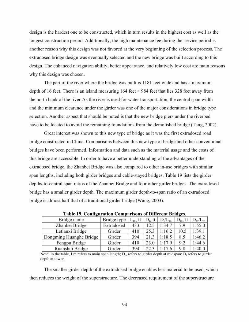
94
design is the hardest one to be constructed, which in turn results in the highest cost as well as the
longest construction period. Additionally, the high maintenance fee during the service period is
another reason why this design was not favored at the very beginning of the selection process. The
extradosed bridge design was eventually selected and the new bridge was built according to this
design. The enhanced navigation ability, better appearance, and relatively low cost are main reasons
why this design was chosen.
The part of the river where the bridge was built is 1181 feet wide and has a maximum
depth of 16 feet. There is an island measuring 164 feet × 984 feet that lies 328 feet away from
the north bank of the river. As the river is used for water transportation, the central span width
and the minimum clearance under the girder was one of the major considerations in bridge type
selection. Another aspect that should be noted is that the new bridge piers under the riverbed
have to be located to avoid the remaining foundations from the demolished bridge (Tang, 2002).
Great interest was shown to this new type of bridge as it was the first extradosed road
bridge constructed in China. Comparisons between this new type of bridge and other conventional
bridges have been performed. Information and data such as the material usage and the costs of
this bridge are accessible. In order to have a better understanding of the advantages of the
extradosed bridge, the Zhanbei Bridge was also compared to other in-use bridges with similar
span lengths, including both girder bridges and cable-stayed bridges. Table 19 lists the girder
depths-to-central span ratios of the Zhanbei Bridge and four other girder bridges. The extradosed
bridge has a smaller girder depth. The maximum girder depth-to-span ratio of an extradosed
bridge is almost half that of a traditional girder bridge (Wang, 2003).
Table 19. Configuration Comparisons of Different Bridges. Bridge name Bridge type Lm, ft Dt, ft Dt/Lm Dm, ft Dm/Lm
Zhanbei Bridge Extradosed 433 12.5 1:34.7 7.9 1:55.0Letianxi Bridge Girder 410 25.3 1:16.2 10.5 1:39.1
Dongming Huanghe Bridge Girder 394 21.3 1:18.5 8.5 1:46.2Fengpu Bridge Girder 410 23.0 1:17.9 9.2 1:44.6
Ruanshui Bridge Girder 394 22.3 1:17.6 9.8 1:40.0Note: In the table, Lm refers to main span length; Dm refers to girder depth at midspan; Dt refers to girder depth at tower.
The smaller girder depth of the extradosed bridge enables less material to be used, which
then reduces the weight of the superstructure. The decreased requirement of the superstructure

95
results in reduced material consumption, labor costs, and construction period. The smaller girder
depth of the extradosed bridge also shortens the bridge approach (Wang, 2003).
The towers of an extradosed bridge are generally shorter than the towers of a cable-stayed
bridge. In the case of the Zhanbei Bridge, the tower height of the extradosed bridge is
approximately half that of a traditional cable-stayed bridge (Wang, 2003). The lower tower
height not only decreases materials consumption but also reduces the construction difficulty. For
example, the technique of cable anchoring in an extradosed bridge is simpler than the anchoring
technique used in a traditional cable-stayed bridge. The simpler technique allows a shorter
construction period, lower requirements for skilled labor, and better construction quality.
Table 20. Materials Consumption Comparisons of Different Bridges. Bridge name Bridge type Concrete
ft3/ft2 Steel strand
lb/ft2 Rebar lb/ft2
Steel cablelb/ft2
Zhanbei Bridge Extradosed 2.46 5.86 25.11 3.13 Letianxi Bridge Girder 2.95 9.07 23.21 -
Dongming Yellow River Bridge Girder 3.08 11.86 22.65 - Fengpu Bridge Girder 2.99 14.17 19.56 -
Ruanshui Bridge Girder 2.79 9.54 18.33 -
Table 20 shows the concrete and steel consumptions of the Zhanbei Bridge and the
same four other girder bridges previously shown in Table 19 (Wang, 2003). The concrete
consumption of the extradosed bridge decreased by approximately 16.7% compared to the
other bridges. In addition, the rebar consumption of the extradosed bridge increased by
approximately 19.6% compared to the other bridges. Even though steel cables were used only
in the extradosed bridge, depending on the amount of concrete and steel used as well as their
prices, the total material costs of concrete and steel in an extradosed bridge are comparable to
that of girder bridges of similar length.
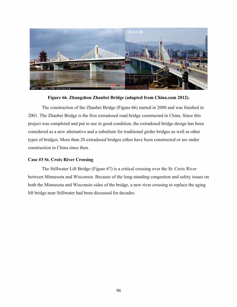
96
Figure 66. Zhangzhou Zhanbei Bridge (adapted from China.com 2012).
The construction of the Zhanbei Bridge (Figure 66) started in 2000 and was finished in
2001. The Zhanbei Bridge is the first extradosed road bridge constructed in China. Since this
project was completed and put to use in good condition, the extradosed bridge design has been
considered as a new alternative and a substitute for traditional girder bridges as well as other
types of bridges. More than 20 extradosed bridges either have been constructed or are under
construction in China since then.
Case #3 St. Croix River Crossing
The Stillwater Lift Bridge (Figure 67) is a critical crossing over the St. Croix River
between Minnesota and Wisconsin. Because of the long-standing congestion and safety issues on
both the Minnesota and Wisconsin sides of the bridge, a new river crossing to replace the aging
lift bridge near Stillwater had been discussed for decades.
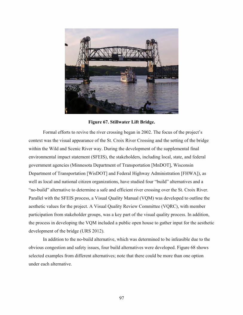
97
Figure 67. Stillwater Lift Bridge.
Formal efforts to revive the river crossing began in 2002. The focus of the project’s
context was the visual appearance of the St. Croix River Crossing and the setting of the bridge
within the Wild and Scenic River way. During the development of the supplemental final
environmental impact statement (SFEIS), the stakeholders, including local, state, and federal
government agencies (Minnesota Department of Transportation [MnDOT], Wisconsin
Department of Transportation [WisDOT] and Federal Highway Administration [FHWA]), as
well as local and national citizen organizations, have studied four “build” alternatives and a
“no-build” alternative to determine a safe and efficient river crossing over the St. Croix River.
Parallel with the SFEIS process, a Visual Quality Manual (VQM) was developed to outline the
aesthetic values for the project. A Visual Quality Review Committee (VQRC), with member
participation from stakeholder groups, was a key part of the visual quality process. In addition,
the process in developing the VQM included a public open house to gather input for the aesthetic
development of the bridge (URS 2012).
In addition to the no-build alternative, which was determined to be infeasible due to the
obvious congestion and safety issues, four build alternatives were developed. Figure 68 shows
selected examples from different alternatives; note that there could be more than one option
under each alternative.

98
(a) B1-2–1500-Foot Cable Stay (b) B1-3–Six 500-Foot Extradosed Box Girders
(c). B1-4–Ten 360-Foot Haunched Concrete Box Girders
(d). C2–500-Foot Concrete Girder Arch and Box Girder Approaches
(e). D1–Three 350-Foot Steel Thru Trusses (f). D2–500-Foot Steel Bowstring Main Span with Five 250-Foot Haunched Concrete
Girders
Figure 68. Selected “Build” Alternatives for St. Croix River Crossing Project Selection.
The preferred alternative was identified through a balanced decision-making process,
which considered the transportation purpose and needs to provide safe and efficient mobility.
During the process, environmental, economic, social, and historic resource concerns present within
the project area were considered. Among all different alternatives, the St. Croix Visual Quality
Review Committee and Project Team (Wisconsin DOT, Minnesota DOT, and Consultant Team)
chose the B1-3 Six 500 Ft Extradosed Box Girders architectural bridge concept for further
development. This concept successfully balances the engineering and functional criteria of cost,
maintenance, and construction means with visual, aesthetic, and architectural project criteria.
Several areas of concern were considered in identifying the optimum bridge type (visibility, height
of towers, quantity of piers in the river) and the effects of piers on the natural environment,
including wildlife, aquatic life, wetlands, and the Wisconsin bluffs.

99
The final project involves a new river crossing structure of segmental concrete
construction, including 3,460 feet of extradosed spans (six 480-foot spans and two 290-foot
end spans). The bridge will provide 40-feet wide roadways in each direction and a 12-foot
wide pedestrian trail. The superstructure will be integrally connected to the substructure at
every pier. Both a double- and a single-box girder cross section are considered viable. Under
the preferred alternative, the old lift bridge will be converted to a pedestrian/bicycle facility
and will be a component of a loop trial connecting Minnesota and Wisconsin via the lift
bridge and new river crossing.
The new St. Croix River Crossing is characterized by three key features. The first feature
is the extradosed bridge type, which is new to the United States. The second feature is the use of
only two expansion joints in the long, continuous length of structure to accommodate thermal
and long-term creep and shrinkage movements of the superstructure. The third feature is the
emphasis on the bridge aesthetics, with particular attention paid to creating a structure with an
“organic” appearance to complement the scenic river setting. The total anticipated project cost is
$299 to $334 million (2004 dollars) with 10% to 90% bid probability and $373 million (2004
dollars) with 100% bid probability.
Case #4 Walterdale River Bridge Replacement
The Walterdale Bridge (see Figure 69) was constructed from 1912 to 1913 with a
three-span structural steel truss design. The bridge was originally designed to carry two lanes of
roadway traffic and a street railway across the North Saskatchewan River in Edmonton, Alberta,
Canada. Through some changes of traffic needs, the bridge currently carries two lanes of
northbound traffic, along with pedestrians and bicyclists on sidewalks on both sides, and a
number of utilities across the river. While the Walterdale Bridge has served Edmonton for a
century and is reaching the end of its service life, a new Walterdale Bridge is needed to replace
the existing bridge.
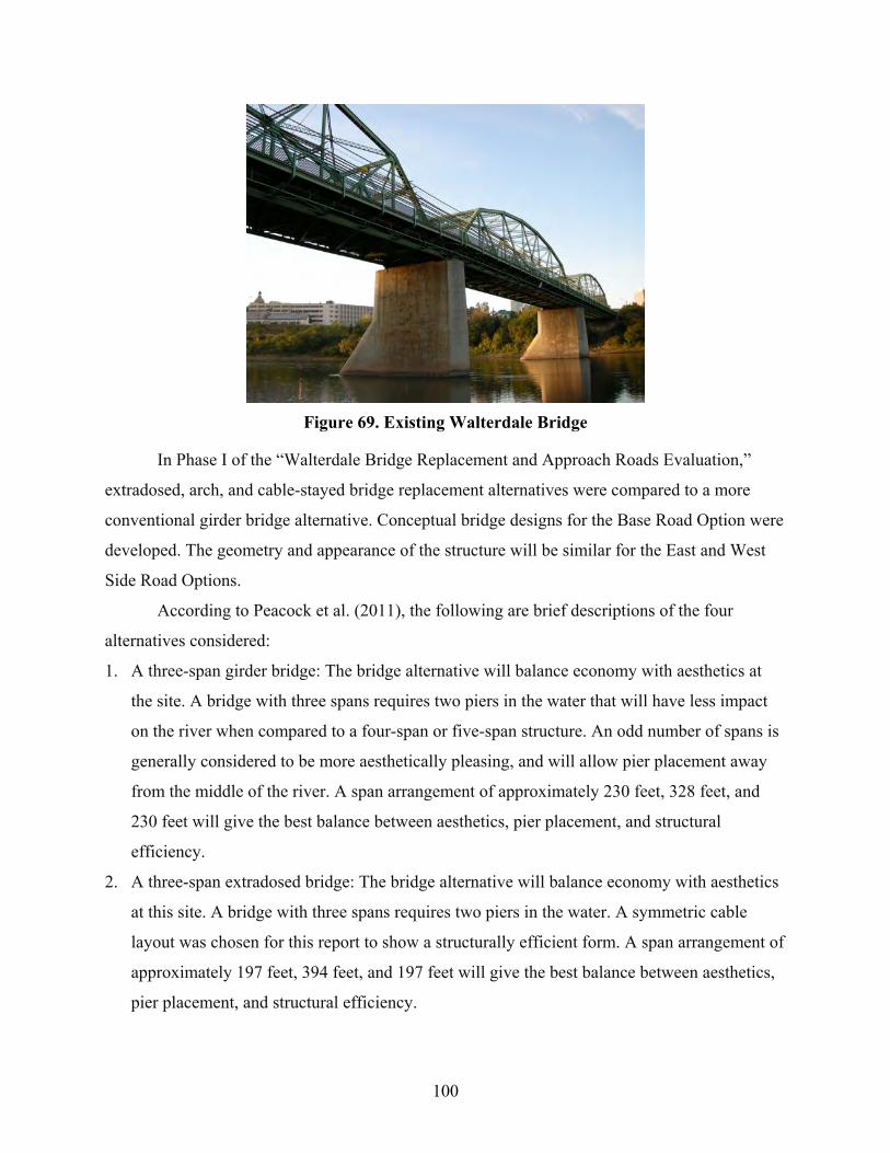
100
Figure 69. Existing Walterdale Bridge
In Phase I of the “Walterdale Bridge Replacement and Approach Roads Evaluation,”
extradosed, arch, and cable-stayed bridge replacement alternatives were compared to a more
conventional girder bridge alternative. Conceptual bridge designs for the Base Road Option were
developed. The geometry and appearance of the structure will be similar for the East and West
Side Road Options.
According to Peacock et al. (2011), the following are brief descriptions of the four
alternatives considered:
1. A three-span girder bridge: The bridge alternative will balance economy with aesthetics at
the site. A bridge with three spans requires two piers in the water that will have less impact
on the river when compared to a four-span or five-span structure. An odd number of spans is
generally considered to be more aesthetically pleasing, and will allow pier placement away
from the middle of the river. A span arrangement of approximately 230 feet, 328 feet, and
230 feet will give the best balance between aesthetics, pier placement, and structural
efficiency.
2. A three-span extradosed bridge: The bridge alternative will balance economy with aesthetics
at this site. A bridge with three spans requires two piers in the water. A symmetric cable
layout was chosen for this report to show a structurally efficient form. A span arrangement of
approximately 197 feet, 394 feet, and 197 feet will give the best balance between aesthetics,
pier placement, and structural efficiency.

101
3. A single span arch bridge: The bridge alternative will carry pedestrians and traffic over the
river without requiring piers in the river. A symmetric arch layout with vertical hanger cables
was chosen for this report to show a simple, clean form. A 787-foot span will be used, with a
height of 131 feet, giving a span to depth ratio of 6. Span to depth ratios can vary; a
shallower arch will have a sleeker appearance but will be less efficient structurally.
4. A single span cable-stayed bridge: The bridge alternative will carry pedestrians and traffic
over the river without requiring piers in the river. An asymmetric, single-tower layout has
been chosen for this report to show a simple, clean form. A 787-foot span will be used, with
a tower height of 394 feet. A shorter tower could be used, but will be less structurally
efficient.
Conceptual bridge designs of the four alternatives are shown in Figure 70.

102
Figure 70. Alternatives of Walterdale Bridge Replacement.

103
In evaluating bridge replacement alternatives, the project team made reference to the
following selection criteria: user experience, views, pedestrian and bicyclist movement, visual
lightness, tower and piers and utilities. According to Peacock et al. (2011), the outstanding
advantages and disadvantages of the four structural alternatives are as follows:
The girder alternative is economical to construct in the Alberta marketplace, and has a
low profile that will have little visual impact on the river valley and adjacent structures. Since it
does not rise above the roadway, the girder alternative will do little to announce the entrance to
downtown Edmonton. The girder alternative will require a deeper girder than the other
alternatives, which will require the approach roadways to be higher and, in turn, will also
increase the footprint in the river valley. Because modern bridges in Alberta are generally
constructed from girders, most people consider this alternative to be commonplace.
The extradosed alternative has been used successfully for bridges throughout the
world, with two notable examples constructed recently in Vancouver. Since the
appearance is considered utilitarian, many people do not believe that this alternative
will become a point of pride for the citizens of Edmonton. This alternative also has
the disadvantage of requiring two piers in the North Saskatchewan River.
The classic arch form has been used for the construction of iconic bridges since
Roman times. This alternative pays homage to the existing bridge, and relates well to
the river valley and the adjacent low level and high level bridges. With arches that
rise above a slender girder, this alternative will become the gateway to downtown and
a point of pride for the citizens of Edmonton if properly designed. To avoid having
piers in the river, a single arch span between the south and north banks was proposed.
Because the erection requires care and attention on the part of the contractor, the cost
of an arch bridge will be in the range of 10 to 20% more than other functional
signature bridges.
In the past 30 years, cable-stayed bridges have been constructed throughout the
world. By virtue of a high tower on the south bank and a slender girder, this
alternative has the potential to become a signature structure in and of itself. However,
many people believe that this alternative will overwhelm the river valley and detract
from the surrounding facilities. The backstay cables and tie-down required for this

104
alternative on the south bank have the potential to complicate the design and
construction of the approach roadways.
Table 21 presents the selected comparison of the girder, extradosed, arch and
cable-stayed alternatives to replace the existing bridge from consideration of the evaluation
criteria.
Table 21. Comparison of Different Alternatives of Walterdale Bridge Replacement. Girder Extradosed Arch Cable-Stayed
Profile Low profile
Higher profile than girder; girder more
slender
Girder very slender; arch quite
prominent
Girder very slender; tower about 3 times
higher than high level bridge
Impact on river Two piers in
river; removal of existing piers
Two piers in river; removal
of existing piers
No piers in river; removal of existing
piers
No piers in river; removal of existing
piers
Constructability
Common bridge type. Segmental
construction required.
Less common bridge type;
more complex than girder
Arch erection complex Requires
well-thought-out girder erection
procedures
Very tall tower Requires
well-thought-out girder erection
procedures
Capital cost Lowest Medium Highest Medium
Operating and maintenance
costs Lowest
Careful detailing will be
required to reduce cable maintenance
costs
Careful detailing will be required to
reduce cable maintenance costs; requires upkeep if paint is used for steel arch ribs
Careful detailing will be required to reduce
cable maintenance costs; expensive to
work at heights when maintaining bridge
Life cycle cost Lowest Medium Highest Medium
Table 22 tabulates preliminary cost estimates for the various bridge alternatives in 2011
dollars. Costs are for the complete construction of the bridge structures including the
superstructure, towers, piers, and abutments, but not including the approach fills, ramps,
retaining walls or other structures required to bring the roads, pedestrians, and bicyclists to the
new bridge.

105
Table 22. Capital Costs of Different Alternatives in Walterdale Bridge Replacement.
Bridge Alternatives
Bridge Area (ft2)
Unit Cost
($/ft2) Cost 30%
ContingencyConstruction
Cost 15% Eng.
and Admin Project
Cost Girder 60,278 604 $36.4 $10.9 $47.3 $7.1 $54.4
Extradosed 60,278 743 $44.8 $13.4 $58.2 $8.7 $66.9 Arch 60,278 929 $56.0 $16.8 $72.8 $10.9 $83.7
Cable-Stayed 61,892 836 $51.8 $15.5 $67.3 $10.1 $77.4 Note: All costs are in millions
Table 23 tabulates life cycle costs for the various bridge alternatives over a 50-year
period (assuming a 75-year lifespan). In preparing the life cycle cost analyses, it was assumed
that minor bridge maintenance will be undertaken every five years, and major rehabilitation will
be needed every 25 years. Minor rehab will include concrete sealer and cable inspections. Major
rehab includes the work completed in a minor rehabilitation plus steel coating replacement,
girder rehabilitation, and cable repairs. A discount rate of 4% was assumed. The total residual
value includes 15% engineering and administration costs.
Table 23. Life Cycle Costs of Different Alternatives in Walterdale Bridge Replacement. Bridge
Alternatives Bridge
Area (ft2) Minor Rehab (Every 5 yrs)
Major Rehab (Year 25)
Major Rehab (Year 50)
50-Year PV Total + Residual
Girder 60,278 $1.5 $5.0 $7.0 $55.1 Extradosed 60,278 $2.5 $7.0 $9.0 $68.4
Arch 60,278 $2.5 $10.0 $12.0 $86.0 Cable-Stayed 61,892 $2.5 $7.0 $9.0 $78.4
As shown in Table 22 and Table 23, both capital and life cycle costs of the extradosed
bridge design were calculated to be relatively low among the four alternatives. Regardless of the
highest cost, as the study progressed in Phase 2, a through-arch bridge was selected as the
preferred alternative. This alternative will carry three lanes of northbound traffic on the
alignment of the approved roadway option, which is located to the east of the existing bridge.
Although any of the four alternatives considered can be designed to be a signature functional
bridge, from consideration of the advantages and disadvantages of each we recommend that the
arch alternative be used for the Walterdale Bridge replacement. The bridge is currently scheduled
for replacement. Construction is scheduled to begin in early 2013, and will continue through
2015. The old bridge is scheduled to be removed from 2015–2016.

106
RECOMMENDED BRIDGE SELECTION PROCEDURE AND CONSIDERATIONS
Based on information as summarized in previous sections, the bridge selection process
can be a complicated process with considerations including engineering requirement, site
condition, constructability, structure, aesthetic, economic, compatibility and environment impact,
and other potential policies and considerations. As different bridges will have different
considerations, it is practically impossible to provide a standard bridge selection process
according to findings from the study. Table 24 shows bridge selection preferences under
different considerations recommended by the research team. Noted that the table is developed
based upon selection among a girder bridge, an extradosed bridge, and a cable-stayed bridge;
some other less common bridge type such as truss and arch bridges are not considered here. In
the table, while “No” generally indicated the alternative should be eliminated from the
consideration, there are 1st, 2nd, and 3rd levels of preference under the category, with 1st
indicated as the most preferable alternative and 3rd indicated as the least preferable alternative.
Table 24. Recommended Bridge Selection Preferences under Different Considerations.
Engineering Requirement
Span <400ft 1st 2nd No Span 400 to 600ft 1st/2nd 1st/2nd No
Span 600 to 1200 ft No 1st/2nd 1st /2nd Span >1200 ft No No Yes
Site Condition
Require Navigation Clearance 3rd 2nd 1st
Height Restriction 1st 2nd 3rd Sharp Curves 1st 2nd 3rd
Structure Consideration
Seismic Consideration 3rd 2nd 1st
Aesthetic Consideration Signature Bridge 3rd 2nd 1st
Other Considerations
Economic 1st 2nd 3rd Environment Impact 3rd 2nd 1st
Figure 71 provided a recommended flowchart for the bridge alternatives selection
process. There are many different considerations included in the selection process. In order to
provide a clear flowchart, instead of providing a flowchart with specific alternatives, the figure
presents prefered bridge alternatives. Generally speaking, it is recommended to have engineering
requirements, i.e., main span range as the first parameter to be considered. While a girder bridge

107
is likely to be the most appropriate alternative for a shorter main span length (particularly those
less than 400 feet), a cable-stayed bridge is more appropriate for a longer main span (particularly
those more than 1200 feet). All three alternatives are feasible for spans ranging between 400 and
1200 feet.
Site condition is the next major factor to be considered in the recommended bridge
alternatives selection process. In a situation where the navigation clearance is required (i.e.,
either a wider space between the bottom of the girder or longer spans for navigation is needed), a
girder bridge often becomes not appropriate due to the thicker girder and shorter span. Height
restriction, either due to limits of aviation or adjacent building heights, will usually lead to the
elimination of the cable-stayed bridge alternative. Sharp curves due to specific site condition, on
the other hand, will make the cable-stayed bridge alternative not feasible due to the longer span
length.
Structure considerations, such as the need to reduce superstructure weight due to the
seismic consideration in earthquake zones, could lead to the elimination of the girder bridge
alternative.
Aesthetic considerations, such as the need for signature bridges, normally lead to either
extradosed bridges or cable-stayed bridges. Other considerations, such as economic, and
environment impact (e.g., the need of less piers in bodies of water) could also lead to the
selection among different alternatives. While a girder bridge is normally the most cost-effective
option, especially in shorter spans, the alternative could also lead to less compatibility and/or
higher environmental impact.
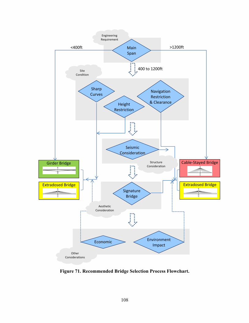
108
Main Span
<400ft >1200ft
Navigation Restriction & ClearanceHeight
Restriction
SeismicConsideration
SignatureBridge
Extradosed Bridge
400 to 1200ft
Sharp Curves
Engineering Requirement
Cable‐Stayed Bridge Girder Bridge
Extradosed Bridge
Economic EnvironmentImpact
Structure Consideration
Site Condition
Aesthetic Consideration
Other Considerations
Figure 71. Recommended Bridge Selection Process Flowchart.
109
SUMMARY
Besides the initial construction costs comparison, life cycle cost analysis (LCCA), value
engineering (VE), and criteria-based bridge selection procedures are commonly used in a bridge
selection process. While there are various advantages and disadvantages noted when extradosed
bridges were compared to girder bridges and cable-stayed bridges, in the long run, aesthetic
(signature bridge and landmark structure), underneath clearance and height restriction, and
construction and structure considerations were identified as the top reasons for selecting the
extradosed bridge over other alternatives. The process of bridge selection should be a
combination of considerations of needs from the public (owners), cost-effectiveness, jobsite
condition, and site restrictions. While bridge selection is a complicated process with many
factors and considerations to be taken into account, span range is usually served as the
preliminary criterion to screen out bridge type alternatives. Other considerations including
aesthetic, constructability, and environmental impact can all be weighed in the decision. The
research team developed the recommended bridge type selection procedure. It proposes using
such considerations as engineering requirement, site conditions, structure considerations,
aesthetic consideration, etc. in screening bridge alternatives.

111
CHAPTER 6. CONCLUSIONS AND RECOMMENDATIONS
CONCLUSIONS
Through a team review of over 350 technical papers, reports, and websites, a total of 120
extradosed bridges from Asia, Europe, North America, South America, and Africa was
identified. A comprehensive literature survey was conducted to summarize status, structural
features, costs, and major reason(s) in selecting extradosed bridges. Interviews of eight experts
with experience in extradosed bridge design and construction were conducted to better
understand extradosed bridges. Questions related to bridge construction, reasons for bridge
selection, cost of construction, advantages and disadvantages, and maintenance and repair were
included in the interview. The following conclusions can be made from the study:
The extradosed bridge is a hybrid design with the girder directly supported by resting on
part of the tower while cable stays act as prestressing cables for a concrete girder. The
basic role of cables in an extradosed bridge is to provide horizontal prestress to the girder
instead of developing elastic vertical actions, as is the case of traditional cable stays. In
addition to those commonly used cable-stayed bridges, girder bridges, arch bridges, and
truss bridges, the unique configuration of extradosed bridge provides an alternative for
bridge selection;
While there is no widely accepted definition of extradosed bridges, according to a statistics
analysis from data of extradosed bridge configurations collected through literature review,
it is recommended to use Ogawa’s and Kasuga’s definition of an extradosed bridge by the
stiffness ratio (load carried by stay cables divided by total vertical load) of less than 30%.
All extradosed bridges identified from the study were found to be using the free balanced
cantilever construction method. Even though there is no specific data to support the
maintenance cost and effort of maintaining extradosed bridges, these are not expected to
be higher compared to typical cable-stayed bridges.
As construction of extradosed bridges spreads out in different countries and different
times, and each bridge was constructed under different site conditions, construction costs
collected from this study were found to be highly variable. Additional cost analyses were
performed with cost information collected from companies with experience in girder
bridges, extradosed bridges, and cable-stayed bridges. Results showed that while an

112
extradosed bridge is generally found to be less expensive compared to a cable-stayed
bridge, the extradosed bridge could be at an advantage to the prestressed girder bridge in
total materials cost due to the resulting reduced quantity of concrete when extradosed
cables are used. In addition, due to the reduced superstructure weight and the resulting
reduced substructure costs, the overall cost of constructing an extradosed bridge might
not be necessarily higher than a girder bridge and therefore could be a more cost-effective
alternative.
While bridge selection is a complicated process with many factors and considerations to
be taken into account, span range is usually served as the preliminary criteria to screen
out bridge type alternatives. Besides cost analyses (both initial construction costs and life
cycle costs), value engineering (VE) and criteria-based bridge selection procedures are
commonly used in the bridge selection process. While there is a variety of advantages
and disadvantages comparing to girder bridge and cable-stayed bridges, aesthetic
(signature bridge and landmark structure), underneath (navigation) clearance, and proper
span lengths were identified as the top reasons for selecting the extradosed bridge over
other alternatives.
The process of bridge selection should combine a consideration of needs from the public
(owners), cost-effectiveness, and jobsite condition and restrictions. The research team
recommended a bridge alternatives selection procedure whereby parameters including
engineering requirement, site conditions, structure considerations, aesthetic and other
considerations are to be used in screening bridge alternatives.

113
RECOMMENDATIONS
The following recommendations were made based on the data collected and knowledge
obtained from the present research work:
1. As the extradosed bridge is still a relatively new concept, one of the major challenges of
constructing this type of bridge is the lack of specifications for bridge design. With the
exception of Japan, there are no widely accepted design rules in the codes that provide
design standards for this bridge type. The Japanese design code (Specifications for
Design and Construction of Cable-Stayed Bridges and Extradosed Bridges) is available
only in Japanese language and the method does not define the extradosed bridge; rather,
it provides a transition between an extradosed bridge cable and a stay cable. A bridge
design specification or guideline is needed for engineers to better understand and utilize
this new type of bridge.
2. While the process of bridge selection can be a combination of considered needs from the
public (owners), cost-effectiveness, and jobsite condition and restrictions, the
recommended bridge type selection procedure that the research team developed can only
serve as a preliminary guideline for bridge selection (with regard to extradosed bridges).
A detailed and comprehensive bridge selection procedure with consideration of life cycle
cost analysis (LCCA), value engineering (VE) and criteria-base bridge selection
procedures could be beneficial to TxDOT.


115
REFERENCES
1. 1000 Friends of Waco, Brazos River Bridge Hearing this Thursday, February 1, 2011. http://www.1000friendsofwaco.com/?p=243. Accessed February 15, 2012.
2. 114NEWS, Hemaxi Technique Study Passing China Railway Company Examination, http://www.114news.com/build/index.html, Accessed April 29, 2012. [in Chinese]
3. 123RF Limited, South bridge in Riga Over the Daugava River. http://www.123rf.com/photo_9949352_south-bridge-in-riga-over-the-daugava-river.html. Accessed February 15, 2012.
4. 163.com, Zhuzhou Lusong Bridge Technology Radiate Splendor, http://a4367007.blog.163.com/blog/static/53124422200910803635990/, Accessed October 28, 2012. [in Chinese]
5. A2C03: Committee on Concrete Bridges, Concrete Bridges. In Transportation Research Board’s Transportation in the New Millennium: State of the Art and Future Directions, Perspectives from Transportation Research Board Standing Committees, 2000
6. AASHTO, Guidelines for Value Engineering 1987, American Association of State Highway and Transportation Officials, Washington, D.C., 2001.
7. ABES Wagner & Partner ZT-GmbH, Smuuli Bridge, http://www.abes.at/eng/portfolio/bridges/smuuli.htm. Accessed February 15, 2012.
8. AEC-INC.JP, The Project for Construction of Naluchi Bridge, Muzaffarabad, http://www.aec-inc.jp/index-6-06E.htm, Accessed October 28, 2012.
9. AECCAFE, Third Karnaphuli Bridge, Bangladesh, http://www10.aeccafe.com/blogs/arch-showcase/2011/02/02/third-karnaphuli-bridge-bangladesh/, Accessed October 28, 2012.
10. Adesanya, A., Frontage Bridges to Enhance Downtown, I-35. The Baylor Lariat, February 4, 2011. http://baylorlariat.com/2011/02/04/frontage-bridges-to-enhance-downtown, Accessed June 25, 2012.
11. Akita, Kanisawa Bridge – Extradosed Bridge (Span 180.0m) – in Akita Prefecture, http://www.ce.akita-u.ac.jp/album/2007/album_0701a_e.htm. Accessed April 22, 2012.
12. Alpine, Domovinski Most Zagreb, http://www.alpine.at/en/bereiche/bruckenbau/domovinski-most-zagreb-hrdomovinski-most-zagreb-hr/. Accessed February 15, 2012.
13. Al-Wazeer, A., Harris, B., and Nutakor, C., Applying LCCA to Bridges, Public Roads, Vol. 69, No. 3, 2005.
14. Anderson R., Use of High Performance Concrete in the Seismic Design of the New Pearl Harbor Memorial Bridge, Presented at ACI Fall 2011 Convention, Pittsburg, 2011.
15. BMEMA.org, Anhui Hailuo Group Co., Ltd., Wuhu Yangtze River Bridge, http://www.bmema.org/user/shili2.asp?pid=20. Accessed April 22, 2012. [in Chinese]
16. Astin, D. Design of the Third Karnaphuli Bridge. In IABSE-JSCE Joint Conference on Advances in Bridge Engineering-II, August 8, 2010a, pp. 257-265.
17. Astin, D., H. Xye, and A. Gillarduzzi. Design and Construction of Third Karnaphuli Bridge, Bangladesh. Bridge Engineering, Vol. 163, No. 4, December 2010b, pp. 161-171.

116
18. Autohome.com.cn, New Bridge to Cross Han River - Sanguanjiang Bridge to Construct, http://www.autohome.com.cn/news/201202/296045.html, Accessed October 28, 2012. [in Chinese]
19. Baidu, Ankang Qiligou Hanjiang Bridge, http://baike.baidu.com/view/2281634.htm?fromTaglist. Accessed February 15, 2012. [in Chinese]
20. Basha, I.M, and A.A. Gab-Allah, Value Engineering in Egyptian Bridge Construction, Journal of Construction Engineering and Management, Vol. 117, No. 3, 1991.
21. Beg, M.A., Z. Zhang, and W.R. Hudson, A Rational Pavement Type Selection Procedure, TxDOT Project Report 0-1734-S, 1998.
22. BBG.CO.KR, Hwangdo Bridge, www.bng.co.kr, Accessed July 20, 2012. [in Koran] 23. Becze, J., and J. Bartz, Korong Prestressed Extradosed Bridge, Structures Engineering
Internal, No. 1, 2006. 24. Benguela, http://benguela.zzl.org/catumbela_bridge.html. Accessed April 24, 2012. 25. Benjumea, J., G. Chio, and E. Maldonado, Structural Behavior and Design Criteria of
Extradosed Bridges: General Insight and State of the Art, Revista Ingenieria de Construccion, Vol. 24, No. 3, 2010.
26. Bergman, D., D. Radojevic, and H. Ibrahim. Design of the Golden Ears Bridge. IABSE Report, No. 93, 2007, pp. 58-61.
27. Bergman, D., A. Griezic, and C. Scollard, Custom Fit. Civil Engineering, Vol. 79, No. 8, 2009, pp. 64-71.
28. Bilfinger Berger Ingenieurbau GmbH, Goldfinger Bridge, http://www.civil.bilfinger.com/, Accessed February 15, 2012.
29. Binns, J. Extra-Dosed Bridge Distinguishes Tollway Project in India, Civil Engineering News, 2005, pp. 20.
30. BJTZZS, Tongzhou will start Building a Fifth Bridge Across Canal Bridge (Tentative planned to be completed in October next year), http://www.bjtzzs.gov.cn/html/xinwenzixun/20061231/257.html, Accessed October 28, 2012. [in Chinese]
31. BlogSpot.com, Sannohe Suspension Bridge, July 26, 2011, http://shari-willinglylostinjapan.blogspot.com/2011/07/sannohe-suspension-bridge.html. Accessed April 22, 2012.
32. BNAMERICAS, Business News Americas, Border Bridge Expected to Open Nov, Business News Americas, August 9, 2005. http://www.bnamericas.com/news/infrastructure/border_bridge_expe... Accessed June 21, 2012.
33. Bridgeworld.net, Seiun Bridge, http://bridgeworld.net/seiun-bridge/, Accessed October 29, 2012. [in Korean]
34. Brinckerhoff, P., St. Croix River Crossing Preliminary Engineering Concept Refinement Report, 2010.
35. Buckland & Taylor Ltd., Design Build of the Canada Line’s River Crossing- The North Arm Bridge. Canadian Consulting Engineer, Vol. 49, No. 6, 2008, pp. 40-42.
36. Buckland & Taylor Ltd., Pearl Harbor Memorial Bridge. Worldwide Bridge Engineering, June 2011. http://www.b-t.com/menu/project/bridgesbytype/extradosedbridges/Pages.aspx. Accessed June 7, 2012.

117
37. Buckland & Taylor. Design and Construction of the Main Span of the Golden Ears Bridge, June 2011. Ltd., http://www.b-t.com/menu/project/designbuild/Pages/Golden-Ears-Bridge.aspx. Accessed February 15, 2012.
38. Buckland & Taylor Ltd., North Arm Bridge, http://www.b-t.com/menu/project/designbuild/Pages/North-Arm-Bridge.aspx. Accessed February 15, 2012.
39. Buyric. Golden Ears Bridge- Costing $5 Million More a Year Than Expected. June 2, 2010. http://www.buyric.com/news/2010/06/golden-ears-bridge-costing-5-milli... Accessed February 15, 2012.
40. B-T.COM, Pearl Harbor Memorial Bridge, http://www.b-t.com/menu/project/bridgesbytype/extradosedbridges/pages/pearl-harbor-memorial-bridge.aspx, Accessed October 28, 2012.
41. Cai, W., Z. Zhou, and T. Lei, Main Bridge Constriction General of Zhangzhou War Preparation Bridge, Bridge Construction, 2002.
42. ABC.es, El viaducto acorta 1,5 kilometros el trayecto de Teror a Las Palmas, http://www.abc.es/20101221/comunidad-canarias/viaducto-acorta-kilometros-trayecto-20101221.html. Accessed February 15, 2012. [In Spanish]
43. CCTV.com, http://jt.cctv.com/html/, Accessed June 20, 2012. [in Chinese] 44. Ceci.com.tw, Taiwan No. 9 Road Improvement Plan,
http://hipcm.ceci.com.tw/public/home.aspx?pd=p00025&ID=cnb1, Accessed October 28 2012. [in Chinese]
45. CEI Report. Golden Ears Bridge Vancouver, Canada. Concrete Engineering International, Vol. 44, No. 3, 2010, pp. 30-32.
46. CH2M HILL, http://www.ch2m.com/corporate/markets/transportation/highways-bridges.asp. Accessed February 15, 2012.
47. Charlon, P., and J. Frappart. Ravine des Trois Bassins Bridge in La Reunion Island. A Successful Application of Extradosed Prestressing. Tailor Made Concrete Structures, 2008, pp. 1147-1148.
48. Chen, C., H. Zhou, and R. Xiao, Recent development of Extradosed Bridges, World Bridges, No. 1, 2006.[ in Chinese]
49. Chinatibetnews.com, Eleven Sections of Najin Bridge to be Completed Next Month, http://www.chinatibetnews.com/shehui/2012-10/19/content_1082989.htm, Accessed October 28, 2012. [in Chinese]
50. CSCEC7bjt.com, China Construction Seventh Engineering Division Traffic Co., Ltd., http://www.cscec7bjt.com/gczs_show.asp?id=42. Accessed February 15, 2012. [in Chinese]
51. Chilstrom, J., Triandafilou, L.N., Stark, W.R., Zaffetti, R.P., Gallucci, C.P., Liberatore, F.R., Stroh, S., Platosh, J., Stahnke, D., Moretti, A.A., Chandra, V., and Giordano, K.E. Extradosed Bridge Technology in Japan and the New Pearl Harbor Memorial Bridge. FHWA, U.S. Department of Transportation, 2001.
52. CCSEBISC.com.cn, China Construction Sixth Engineering Bureau Infrastructure Services Company, Pingdingshan Kaifa Road Zhanhe Bridge, July 11, 2011, http://www.ccsebisc.com.cn/Heda_content.asp?channelid=45&classid=13&id=97. Accessed February 15, 2012. [in Chinese]
53. CRFSDI.com.cn, China Railway Siyuan Survey and Design Group Co., Ltd., http://www.crfsdi.com.cn/show.asp?id=248. Accessed February 15, 2012.

118
54. China.com, Zhangzhou Zhanbei Bridge to be Renamed, http://club.china.com/data/thread/1011/2730/19/50/7_1.html. Accessed April 22, 2012.
55. ChnRoad.com, Shaanxi Ankang Qiligou Bridge to Complete Closure, August 1, s008, http://www.chnroad.com/industrynews/newsread.asp?id=7026. Accessed April 23, 2012. [in Chinese]
56. Cho, Y., S. Kim, J. Park, and S. Lee, Design & Construction of PSC Box-Girder Bridge With Central Suspension by Extradosed Cables and Constant Girder Depth, 2003. [in Korean]
57. Christian, J. and L. Newton, Highway Construction and Maintenance Costs, Canadian Journal of Civil Engineering, 26, 1999
58. City of Konin, Crossing the Warta- A New Course of National Road 25. http://www.nowymost.konin.pl/index.php?page=7. Accessed February 15, 2012. [in Polish]
59. Clark, J.A., Value Engineering for Small Transportation Projects, Thesis, Worcester Polytechnic Institute, 1999
60. CNBRIDGE, China Bridge Web, http://baike.cnbridge.cn, Accessed October 28, 2012. [in Chinese]
61. CNKI, Ankang Qiligou Han River Bridge Dwarf Tower Cable-Stayed Main Beam Construction Technology, http://mall.cnki.net/magazine/article/xbjt200803018.htm, Accessed October 28, 2012. [in Chinese]
62. Construction News, Mota-Engil in Angola in the final stage of the Catumbela Bridge, http://home.nestor.minsk.by/build/news/2009/08/3104.html. Accessed April 24, 2012.
63. Cr13g-lc.com, The Smooth Wrap up of the Main Bridge Underwater Engineering Jian'an Company Ningjiang Songhua River Bridge, November 11, 2011, http://www.cr13g-1c.com/ReadNews.asp?NewsID=747, Accessed October 28, 2012. [in Chinese]
64. Cridlebaugh, B. Bridge Basics. Bridges & Tunnels of Allegheny County & Pittsburg, PA. http://pghbridges.com/basics.htm. Accessed March 3, 2011.
65. Crototis, R., B. Beams, D. Hattan. Comprehensive Risk Analysis for Structure Type Selection. Report No. CDOT-2010-2, Colorado Department of Transportation, 2010.
66. CSCEC7BJT, China Construction Seventh Engineering Division Traffic Co. LTD., http://www.cscec7bjt.com/gczs_show.asp?id=42, Accessed October 28, 2012. [in Chinese]
67. CTCECC, http://ctcecc.com/, Accessed June 16, 2012. [in Chinese] 68. CTDOT, Project Description: I-95 new Haven Harbor Crossing Corridor Improvement
Program, Colorado Department of Transportation, 2012. 69. Dabous, S.A. and S. Alkass, A Multi-attribute Ranking Method for Bridge Management,
Engineering, Construction and Architectural Management, Vol. 17, No. 3, 2010. 70. Dabous, S.A. and S. Alkass, Decision support method for multi-criteria selection of
bridge rehabilitation strategy, Construction Management and Economics, No. 26, 2008. 71. DAHE.com, Kaifeng Yellow River Bridge: Natural Moat Thoroughfare Henan Bridge,
http://www.dahe.cn/hnxw/shmtdd/dhb/t20060718_580505.htm, Accessed October 28, 2012. [in Chinese]
72. DAUM, http://cafe.daum.net/projectgroup, Accessed October 28, 2012. [in Korean] 73. Dienvidu Tilts, http://www.dienvidutilts.lv/index.php?lang_id=2&menu_id=40.
Accessed February 15, 2012.

119
74. DM Engineering Co., Ltd., Extradosed & Arch Bridges, www.dm-eng.com/img/main/DM_Engineering_Brochure.pdf, Accessed October 28, 2012.
75. Dnevnik Mucke, The bridge that Connects Zagreb with Nothing, http://pollitika.com/most-koji-spaja-zagreb-sa-nicim. Accessed February 15, 2012. [in Croatian]
76. Dnevnik.hr, Homeland Bridge is Finally Open. May 5, 2007. http://dnevnik.hr/vijesti/hrvatska/otvoren-najveci-most-u-hrvatskoj.html. Accessed February 15, 2012. [in Serbian]
77. Dong, J., Construction of Pile Caps of Pushang Bridge, Fuzhou with Combined Steel Sheet Pile and Steel Boxed Cofferdam, The 2nd Engineering Co., Ltd., March 2006, pp. 68-70. [in Chinese]
78. Drinkwater, L. J. Analysis of the Sunniberg Bridge. Proceedings of Bridge Engineering 2 Conference, Bath University, Bath, UK, 2007.
79. Dunham, J.S, W. Bonzon, K. Stiff, S. Stroh, and A. Moretti. New England’s Gateway: the Pearl Harbor Memorial Bridge. Concrete Technology Today, Vol. 2, 2010, pp. 48-52.
80. DYWIDAG-Systems International, http://www.dywidag-systems.com/references/bridges/sannai-maruyama-overpass-bridge-japan.html. Accessed April 24, 2012.
81. E-KONSTRUKCIJE.SI, "Puh Bridge" over the river Drava Ptuj, http://www.e-konstrukcije.si/index.php?PageID=65, Accessed October 28, 2012. [in Slovenian]
82. Echizenya, H., M. Hasegawa, K. Tachibana, and H. Nunoshita, Design and Construction of Yukizawa Bridge, Vol. 42, No. 5, 2000. [in Japanese]
83. Edmonton.ca, Walterdale Bridge FAQ, http://www.edmonton.ca/transportation/RoadsTraffic/H3-WalterdaleBridge_HistoricalResourcesFAQ_08022012.pdf, Accessed October 30, 2012.
84. EEmap.org, Liaoning Dalian Changhai Changshan Bridge, http://www.eemap.org/id/66502. Accessed April 22, 2012. [in Chinese]
85. Ehlen, M.A., Agencies Gain a Bridge Lifecycle Assessment Tool-Software Program Standardizes Materials and Design Comparisons. Bridge Builder, 1999.
86. Ehlen, M.A., Life-cycle Costs of New Construction Material”, Journal of Infrastructure Systems, 1997.
87. Ehlen, M.A., The Economics of Composites in Highway Bridges, CDA Winter, 1996 88. Eipsa S.L., Bridge over the River Deba,
http://www.eipsa.net/es/ficha_proyecto.asp?id_proyecto=11. Accessed February 15, 2012. [in Spanish]
89. Epitos.blog.hu, Suspended Bridges, Prestressed, http://epitos.blog.hu/2009/07/30/feszitett_fuggesztett_hidak. Accessed February 15, 2012. [in Hungarian]
90. Faber, M., R. Rackwitz. Sustainable Decision Making in Civil Engineering. Structural Engineering International, 2004.
91. Fang, Q. The Wuhu Yangtze River Bridge, Journal of Huazhong University of Science and Technology, Vol. 19, No. 1, 2002, pp. 1-3.
92. Feng, M. China’s Major Bridges, International Association for Bridge and Structural Engineers, undated.
93. Figi, H., C. Menn, D.J. Bänziger, and A. Bacchetta, Sunniberg Bridge, Klosters, Switzerland, Structural Engineering International, Vol. 7, No. 1, 1997, pp. 6-8.
120
94. Lusas.com, Finite Element Analysis Ltd., Cable Stayed Bridge over the River Labe at Nymburk. January 2010. http://www.lusas.com/case/bridge/river_labe_nymburk.html. Accessed February 15, 2012.
95. Finley Engineering Group. Finley Provides Bridge Construction Engineering Service for First “Extradosed” Bridge Design in Texas. June 27, 2012. www.finleyengineering group.com. Accessed July 5, 2012.
96. Frangopol, D.M., J.S. Kong, and E.S. Gharaibeh, Reliability-Based Life-Cycle Management of Highway Bridges, Journal of Computing in Civil Engineering, 2001.
97. GangaRao H.V.S., R. Wade, R., and V. Howser, Value Engineering Approach to Low-Volume Road Bridge Selection. Journal of Structural Engineering, Vol. 114, No. 9, 1988.
98. Gao, F., Z. Chen, L. Yang, and Y. Wang, Mechanical Characteristics Analysis of Partially Cable-stayed Bridge. Journal of Zhengzhou University, Vol. 26, No. 1, 2005, pp.54-56.
99. Grc.com.pk, 100. Go.JP, Construction of the Immobility Bridge,
http://www.ktr.mlit.go.jp/ktr_content/content/000041527.pdf, Accessed October 28, 2012. [in Japanese]
101. Godzwon, G. Bridge Asset Management. Government Engineering, No. 5, 2004. 102. Gov.cn, Chongqing Jiayue Bridge Opens for Traffic, February 11, 2010,
http://www.gov.cn/jrzg/2010-02/11/content_1533644.htm, Accessed October 28, 2012. [in Chinese]
103. GRC.COM.PK, Ghulam Rasool & Company(Pvt) Ltd. Construction of West Bank Bypass Project (Package-01) Muzaffarabad, AJK Extradosed Box Girder Bridge. http://grc.com.pk/br8.php. Accessed June 26, 2012.
104. TOPIX.COM, New bridge to come up in Muzaffarabad, http://www.topix.com/forum/world/pakistan/TBRVBT7IT2TJOI0HE, Accessed October 28, 2012.
105. GRID, Ltd., http://www.grid.pt/homeE.htm. Accessed February 15, 2012. 106. Gridnev, A. The South Bridge Project, Riga, Latvia. Tilts, undated. 107. Griezic, A., Scollard C.R., Bergman D.W., Design of the First Extradosed Transit
Bridge in North America, undated. 108. Guardian News and Media Limited, Pacific-Atlantic Route Drives up Fears of
Crime and Destruction, http://www.guardian.co.uk/environment/2011/jul/14/pacific-atlantic-route-brazil-peru. Accessed February 15, 2012.
109. H2L2, Quinnipiac Bridge, http://www.h2l2.com/infrastructure_gallery_13.php. Accessed February 15, 2012.
110. Hawk, H., Bridge Life-Cycle Cost Analysis, NCHRP Synthesis 483, Transportation Research Board, 2003.
111. He, X. Structural Analysis of Main Spans of Lishi Viaduct. Highway, No. 5, 2004a, pp. 68-70. [in Chinese]
112. He, X., Design of Low Tower Cable-Stayed Bridge, Journal of Highway and Transportation Research and Development, Vol. 21, No. 4, 2004b, pp.66-69. [in Chinese]
113. He, X., Y. Hu, Q. Ding, and J. Chen. Liuzhou Sanmenjiang Bridge Stayed Cable Construction Technique, Railway Engineering, Vol. 4, 2007, pp. 14-15. [in Chinese]

121
114. Hearn, G., Purvis, R.L., Thompson, P., Bushman, W.H., McGhee, K.K., and McKeel W.T. Jr., Bridge Maintenance and Management – A look to the future, Transportation Research Board A306, undated.
115. Heller, A. The Third Karnaphuli Bridge, Bangladesh. Internet Business Systems, Inc., February 2011. http://www10.aeccafe.com/blogs/arch-showcase/2011/02/02/third-karnaphuli-bridge-bangladesh/. Accessed April 24, 2012.
116. HighestBridges.com, Tounoyamahattoku Bridge, http://www.highestbridges.com/wiki/index.php?title=tokunoyamahattoku... Accessed June 20, 2012.
117. Hino, S. The Great Himiyume Bridge, Highway Entrance to Nagasaki; The World First Extra-Dosed Bridge Using Corrugated Steel Plate Webs. Kyushu University, 2005, pp. 1-6.
118. Hoher, The Puli Line - Acer Bees Ecological Farm, July 13, 2010, http://hoher.idv.tw/blog/read-1597.html. Accessed February 15, 2012. [in Chinese]
119. Hohmann, D. Project Development and Design. Bridge Engineering Program-Distinguished Speaker Series. University at Buffalo. 2011.
120. Honigmann, C., D. P. Billington, and M. Hon. Conceptual Design for the Sunniberg Bridge. Journal of Bridge Engineering, Vol. 8, No. 3, 2003, pp.122-130.
121. Hu, Y. Control Technology for the Temperature of Massive Concrete for Liuzhou Sanmenjiang Bridge, Journal of Railway Engineering Society, Vol. 130, No. 7, 2009, pp. 62-66. [in Chinese]
122. Hu, Y., Q. Ding, and Z. Yan, Wide Girder Bridge Guyed Travelers Design and Stress Analysis. Hunan Communication Science and Technology, Vol.33, No. 1, 2007, pp. 105-108. [in Chinese]
123. Huang R., A Performance-based Bridge LCCA Model Using Visual Inspection Inventory Data, Construction Management and Economic, 24, 2006.
124. Hui X., Overview of Chang Cheng Road Beijing-Hangzhou Canal Bridge Construction Management, Jiangsu Transportation Engineering, No. 5, 2003. [in Chinese]
125. HUIMIN.gov.cn, Huiqing Yellow River Bridge Style Show, http://www.huimin.gov.cn/art/2008/12/23/art_121_9126.html, Accessed October 28, 2012. [in Chinese]
126. HWM2, Cable-stayed Bridges, Fin Back Bridges, and Extradosed Bridges, http://hwm2.gyao.ne.jp/kappaclub/bridge05.html, Accessed October 28, 2012. [in Japanese]
127. Hyundae. Construction, Design and Construction of Extradosed Bridges, undated. [in Korean]
128. I95newhaven.com, I-95 New Haven Harbor Crossing Corridor Improvement Program, http://www.i95newhaven.com/. Accessed February 15, 2012.
129. Ikeda, S., and A. Kasuga, Development of Extradosed Structures in the Bridge Construction. 25th Conference on Our World in Concrete & Structures. Singapore, 2010.
130. Ikeda, S., and A. Kasuga, Performance-Creative Design Concept for Concrete Infrastructure. 25th Conference on Our World in Concrete & Structures. Singapore, 2010.

122
131. Infonortedigital.com, Teror Celebrates Viaduct on 28 and 29 January, http://www.infonortedigital.com/portada/portada/6- interes/2921-teror-celebra-la-apertura-del-viaducto-el-28-y-29-de-enero. Accessed February 15, 2012.
132. Institute of Metal Constructions, Puhova Bridge in Ptuj. http://www.e-konstrukcije.si/index.php?PageID=65. Accessed February 15, 2012.
133. IBT, International Bridge Technologies, Inc., Second Vivekananda Bridge Tollway- Kolkata, India, http://www.ibtengineers.com/PROJECTS/Vivekananda/Vivekananda1.html. Accessed April 24, 2012.
134. Ishii, M., Structural Systems for Extradosed Bridges, Dissertation, Polytechnic School of the University of São Paulo, 2006. [in Portuguese]
135. IZS, Puh Bridge in Ptuj, http://www.izs.si/dobra-praksa/primeri-dobre-prakse/inzenirski-objekti/puhov-most-na-ptuju/, Accessed October 28, 2012.
136. JBSI, Japan Bridge & Structure Institute, Inc., Prize Winning Cable-Stayed and Extradosed Bridges, http://www.jbsi.co.jp/works/03.html, Access October 28, 2012. [in Japanese]
137. Jica.go.jp, Japan International Cooperation Agency, Second Mandaue – Mactan Bridge Construction Project, http://www.jica.go.jp/english/operations/evaluation/oda_loan/post/2002/pdf/082_full.pdf, 2002.
138. Jsce.or.jp, Japan Society of Civil Engineering, http://www.jsce.or.jp/committee/tanaka-sho/jyushou/sakuhin.htm. Accessed April 22, 2012. [in Japanese]
139. Jau, W. and S. Li The Monitoring of an Extra-Dosed Bridge, The Rational and Design. National Chiao-Tung University, Hsinchu 300, Taiwan.
140. Jawad, D., and K.Ozbay, Probabilistic Lifecycle Cost Optimization for Pavement Management at the Project-Level. Transportation Research Board, 2006.
141. Joseph, E. C. et. al. Extradosed Bridge Technology in Japan and the New Pearl Harbor Memorial Bridge. Federal Highway Administration, Connecticut. Dept. of Transportation, 2001.
142. JPCEA Awards, Sannai Maruyama Bridge, http://www.jpcea.or.jp/eng-jjjj/eng-h20-gijyutu-kyoukai-syou-soukai.htm. Accessed April 24, 2012.
143. JSCE, Japan Society of Civil Engineers Tanka Prize Work for 2000. [in Japanese] 144. Kajima Co., Shikari Bridge, http://www.kajima.co.jp/project/works/ex/shikari-
bridge.html. Accessed April 22, 2012. [in Japanese] 145. Kalny, M., V. Kvasnicka, P. Nemec, I. Batal, J. Chmelik, and P. Stedronsky.
Cable Stayed Bridge Over the Labe At Nymburk. Bridges Mostly, No. 3, 2009, pp. 18-23. 146. Taiwan Today, Kaohsiung City’s New Qishan Bridge Inaugurated, January 2011.
http://taiwantoday.tw/ct.asp?xItem=144606&CtNode=436. Accessed June 25, 2012. 147. Kasuga, A., Development of a New Bridge Construction Method using
Suspension Structures, Structural Concrete, Vol. 12, No. 2, 2011, pp. 65-75. 148. Kasuga, A., Construction of Arch Bridges in Japan, in fib Symposium PRAGUE
2011. 149. Kasuga, A. Extradosed bridges in Japan. Structural Concrete, Vol. 7, No. 3, 2006,
pp. 91-103.

123
150. Kazimierz P., Konin is to Bridge the European Union, http://www.palasz.konin.pl/index.php?page=3. Accessed February 15, 2012.
151. Keoleian, G.A., A. Kendall, R. Chandler, G.E. Helfand, M. Lepech, and V.C. Li, Life Cycle Cost Model for Evaluating the Sustainability of Bridge Girders, in Advances in Life-Cycle Cost Analysis and Design of Civil Infrastructure Systems, 2001.
152. Kim, S.H., J.W. Seo, Y.B. Lee, I.H. Seo, Construction Planning and Analysis of Six Continuous Extradosed PSC Bridge, Taylor & Francis Group, London, 2008.
153. Klaiber F.W., T.J. Wipf, and F.M. Russo, Cost-Effective Practices for Off-System and Local Interest Bridges, NCHRP Synthesis 327, 2004.
154. Ko, T. The Environmental Consideration in Planning and Construction of the National Highway No. 6, In Proceedings of Fourth U.S.-Taiwan Bridge Engineering Workshop, Princeton, New Jersey. 2008.
155. Koh, H., J. Choo, Recent Major Bridges in Korea, International Association for Bridge and Structural Engineering, undated.
156. Komiya, M., A Characteristics and Design of PC Bridges with large Eccentric Cables (PC Extradosed Bridge), Japan Bridge & Structure Institute, Inc., 1999.
157. Konstrukce Media, s.r.o., Highway Viaduct over Povazska Bystrica, http://www.silnice-zeleznice.cz/clanek/dalnicni-estakada-nad-povazskou-bystricou/. Accessed February 15, 2012. [in Czech]
158. Konstrukce Media, s.r.o., Urban overpass in Považská Bystrica, http://www.silnice-zeleznice.cz/clanek/mestska-estakada-v-povazskej-bystrici/. Accessed February 15, 2012.
159. Kurita, A., O. Ohyama. Recent Steel-Concrete Hybrid Bridges in Japan. Steel Structures, 2003, pp. 271-279.
160. L&T IDPL., Second Vivekananda Bridge (Kolkata), http://www.lntidpl.com/second-vivekananda-bridge.aspx. Accessed April 24, 2012.
161. News.lnd.com.cn, The Changshan Bridge to be Delivered Next Year, http://news.lnd.com.cn/htm/2012-02/29/content_2184174.htm, Accessed October 28, 2012. [in Chinese]
162. Lai Z., Review of National Highway Construction, 2009. [in Chinese] 163. LBM.RLP.DE, Landesbetrieb Mobilitat Rheinland-Pfalz, Wash Mühltal Bridge
and Sounds, http://www.lbm.rlp.de/icc/Internet/nav/c5f/broker.jsp?uMen=c5f2eb9d-9139-9219-13a7-697a7fd72763&uCon=142605a2-9ce3-6a21-c770-0bb40a7fd727&uTem=aaaaaaaa-aaaa-aaaa-aaaa-000000000011. Accessed February 15, 2012. [in German]
164. Lane Construction Corporation, I-35 Improvements, Mcclennan County, TX. Laneconstruct.com, April 2012.
165. Leonhardt, Andra und Partner. Gumgang Bridge No.1. www.lap-consult.com/english/e_projekt.php?sp=00306&kat=. Accessed April 29, 2012.
166. Li B., Line-type Control of 3# Cable-Stayed Bridge of Lishi Viaduct, Shanxi Architecture, Vol. 34, No. 21, 2008. [in Chinese]
167. Li, H., Designing the Type for Lanzhou Xiaoxihu Major Bridge Over Yellow River. Journal of Northwest Institute of Architectural Engineering, Vol 19, No. 4, 2002, pp. 29-36. [in Chinese]
168. Li, J., Wide Girder Extradosed Bridge Design and Construction, Railway Construction, Vol. 8, 2006, pp. 9-10. [in Chinese]

124
169. Li, S., and M. Zeng, Design of Yinhu Bridge in Xiamen. Bridge Design, Vol. 4, 2002. pp. 43-46. [in Chinese]
170. Li, X., and R. Xiao, Mechanical Behavior Analysis and Design Experience of Low-Pylon Cable-Stayed Bridge. Structural Engineers, Vol. 21. No. 4. 2005. [in Chinese]
171. Liao, J., and T.Chen, Design of Zhuzhou Husong Bridge partial Cable-Stayed Bridge, China and International Road, vol. 26, No., 3, 2006. [in Chinese]
172. LibertyTimes.com, Halfsky Viaduct Breakgound on the 20th, http://www.libertytimes.com.tw/, Accessed October 28, 2012. [in Chinese]
173. Lin, P., F. Liu, S. Zhou, S. Liu. Mechanical Characteristics and Defining of Extradosed Bridges. Journal of the China Railway Society, Vol. 29, No. 2, 2007. [in Chinese]
174. Lin S., and Y. Guo, Design and Construction of National Highway 6 Doushan No. 2 Viaduct, Zhongxin Engineering, No. 105, pp. 43-50, 2009. [in Chinese]
175. Liu, S. Q. Chen, and S. Li. Tongan Yinhu Single Pylon Partial One-Side Cable-Stayed Bridge. Journal of Highway and Transportation Research and Development, Vol. 23, No. 5, 2006, pp. 57-59. [in Chinese]
176. Liu, X., Z. Qin, Y.W. Leung, and L. Yue, Construction of the Precast Segmental Approach Structures for Sutong Bridge, undated.
177. Liu, X., C. Guo and J. Li, Stay Cables Design of Pingdingshan Kaifa Road Zhanhe No. 1 Bridge, Henan Science, Vol. 22, No. 4, 2004. [in Chinese]
178. Liu, Z., S. Meng, H. Zang, and Y. Zhang, Model Test and Design Investigation on Saddle Deviator Zone of Extra-dosed Bridge, Journal of Southeast University, Vol. 37, No. 2, 2007. [in Chinese]
179. Liu Z. and K. Zheng, Optimization of Rigidity of Extradosed Bridge Piers, Shanxi Architecture, Vol. 33, No. 31, 2007. [in Chinese]
180. Liuzhou OVM Machinery Co., Ltd., Extra-Dosed Bridge, http://www.ovmchina.com/ovmweb-e/EECenter/InfoView.aspx?infoId=310&eetypeId=3&SearchValue=. Accessed April 24, 2012.
181. Llombart Jaques, J. A., J. Revoltós Fort, and J. Fernández Vega, Viaducto Sobre el Barranco de Teror. Accessed February 15, 2012.
182. Llombart, J. A., and J. Revoltós. Extradosed Bridge over the river Deba. Realizaciones, 2004.
183. Lookbridges.com, Ganter Bridge in Brig, Switzerland, http://lookbridges.com/ganter-bridge-in-brig-switzerland, Accessed October 29, 2012.
184. Lopez-Anido, R., Life-Cycle Cost Survey of Concrete Bridge Girders – A Benchmark for FRP Bridge Girder Replacement, in Transportation Research Board, Washington D.C., 201.
185. LQBK, Road and Bridge Engineers, http://baike.lqgcs.com/, Accessed October 28, 2012. [in Chinese]
186. lumontad_777, http://wikimapia.org/showphoto/?obj=1266735&type=1&lng=0&id=422988. Accessed April 22, 2012.
187. LUSAS Bridge, Cable Stayed Bridge over the River Labe at Nymburk, http://lusas.com/case/bridge/, Accessed March 19, 2012.

125
188. Markelj, V., The First Extradosed Bridge in Slovenia, Structural Engineering International, 2010, pp. 462-467.
189. Matascik, M., Municipal Flyover In Povazska Bystrica, Silnice Zeleznice, July 2010. Translate.googleusercontent.com/translate_c?client=tmpg&hl=en&langpair=cs%7Cen&rurl=translate.go… Accessed March 19, 2012.
190. Matyassy, L., Construction of the Tisza-Bridge Spanning the River on the Motor Road M43, Concrete Structures, 2010, pp. 29-31.
191. May, Korea’s Newest City to Have Two Dramatic Bridges. Bridge Design & Engineering, Vol. 51, 2008, pp. 35.
192. McGowan, C., Brazos River Bridge Hearing This Thursday. February 2011. www.1000friendsofwaco.com/?p=243. Accessed April 25, 2012.
193. Merko, http://www.merko.ee/eng/contact. Accessed February 15, 2012. 194. Mermigas, K.K., Behavior and Design of Extradosed Bridges, Master thesis,
Analysis: State-of-the-practice vs. State-of-the-art, University of Toronto, 2008, 83rd in Annual Meeting of the Transportation Research Board, 2004.
195. Metrostav, http://www.metrostav.cz/en/contacts/adresar. Accessed February 15, 2012.
196. Middlesex Companies, http://www.middlesexcompanies.com/withoutsound/contact.html. Accessed February 15, 2012.
197. Minnesota Department of Transportation, http://www.dot.state.mn.us/metro/projects/stcroix/contacts.html. Accessed February 15, 2012.
198. MnDOT, WIDOT and FHWA, Supplemental Final Environmental Impact Statement – St. Croix River Crossing Project, Minnesota Department of Transportation, Wisconsin Department of Transportation and Federal Highway Administration, June 2006.
199. Mohammadi, J., S. Guralnick, Y, Li. Incorporating Life-Cycle Cost in Highway-Bridge Planning and Design. Journal of Transportation Engineering, 1995, pp. 417-424.
200. Moore, M., TxDOT to Break Ground on New Brazos Bridges in Late Summer 2012. Our Daily Bears, April 17, 2012. Ourdailybears.com/…txdot-to-break-ground-on-new-brazos-bridges-in-late-summer-2012-baylor-stad… Accessed April 29, 2012.
201. Mutsuyoshi, H., D.H. Nguyen, and A. Kasuga, Recent Technology of Prestressed Concrete Bridges in Japan, in IABSE-JSCE Joint Conference on Advances in Bridge Engineering-II, Dhaka, Bangladesh, 2010.
202. Myaena.net, Halfsky Viaduct Bridge to Break Ground, to become the Tallest Extradosed Bridge in Taiwan, http://myaena.net/newspaper.php?nn_id=54&news_id=1067, Accessed October 28, 2012. [in Chinese]
203. Nantou.gov.tw, The Overpass Construction in HalfSky area Begins, Will be the Tallest Extradosed Bridge in Taiwan, http://www.nantou.gov.tw/english/hotnewsdetail.asp?dptid=376480000&catetype=02&cid=519&cid1=522&mcid=63642, Accessed October 28, 2012. [in Chinese]

126
204. Nazret.com, Ethiopia's First Extradosed Bridge to Span the Blue Nile Gorge, http://nazret.com/blog/index.php/2008/09/06/ethiopia_s_first_extradosed_bridge_to_sp, Accessed October 28, 2012.
205. Naver.com, Start Extradosed School, http://blog.naver.com/PostView.nhn?blogId=bi1he2s3&logNo=100014722735&redirect=Dlog&widgetTypeCall=true. Accessed April 22, 2012. [in Korean]
206. Naqash, T. New Bridge to Come Up in Muzaffarabad. Greater Kashmir, March 2009. www.greaterkashmir.com/news/2009/mar/3/new-bridge-to-come-up-in-muzaffarabad-34.asp. Accessed April 29, 2012.
207. News.cn, The Najin Bridge to be bided, to be Built as a Low Tower Cable-stayed Bridge, November 11, 2010, http://tibet.news.cn/gdbb/2010-11/11/content_21367711.htm. Accessed February 15, 2012. [in Chinese]
208. NewsToday, Karnaphuli Bridge-III opens to Traffic, http://www.newstoday.com.bd/index.php?option=details&news_id=7008&date=2010-09-09, Accessed October 28, 2012.
209. NiPic.com, Pictures of the Xiaoxihu Yellow River Bridge from South Band of the Yellow River, http://www.nipic.com/show/1/62/4533804k812a7f9d.html. Accessed April 22, 2012.
210. Niwa J., The Transition of Bridge Technology seen from the Construction of Amarube Bridge Replacement, Kawada Technical Report, Vol. 2010. [in Japanese]
211. Normile, D., Extradosed Box Girder Span Exposes Prestressed Cables, Odawara. ENR, February 21, 1994. pp. 20
212. Soil and Structures, Noteworthy Strapped Cables and Multitube Saddles, Soil and Structures, 2007, pp.18.
213. konin.pl, Bridge of the European Union, December 15, 2007, http://nowymost.konin.pl/, Accessed March 19, 2012.
214. Nuruzzaman, A.S., Lessons Learnt From the Design and Construction of Third Karnaphuli Bridge: The First Extra-Dosed Cable Stayed Bridge of Bangladesh, in Proceedings of IABSE-JSCE Joint Conference on Advances in Bridge Engineering- 2, Dahka, Bangladesh, 2010pp.77-92.
215. O&G Industries, Inc., http://www.ogind.com/contact.aspx?id=136. Accessed February 15, 2012.
216. bandadeteror.com, Opening of the New Viaduct Teror, La Banda, January 2011. www.bandadeteror.com/web/content/inauguracion-del-nuevo-viaducto-de-teror. Accessed April 29, 2012. [in Spanish]
217. Orangebd Ltd. Karnaphuli Bridge Opens to Traffic. 2010. http://www.thefinancialexpress-bd.com/more.php?news_id=111569&date=2010-09-08, Accessed February 15, 2012.
218. Tok2.com, Overview of the Bridge East Chestnut, www.42.tok2.com/home/h-nagai/bridge/rittoh-br/rittoh-bridge.htm. Accessed April 23, 2012.
219. Ozbay, K., D. Jawad, N.A. Parker, S. Hussain, and J. Pang. Life Cycle Cost 220. Key Construction Technology in Prestressed Concrete Partial Cable-stayed
Bridges. Railway Construction Technology, Vol. 4, 2006, pp.7-10. 221. konin.pl, Konin is to bridge the European Union,
http://www.palasz.konin.pl/index.php?page=3, Accessed October 28, 2012. [in Polish]
127
222. Pang, J., Key Construction Technology in Prestressed Concrete Partial Cable-stayed Bridges, Railway Construction Technology, No. 4, 2006. [in Chinese]
223. Park, E., K. Jung, Y. Shin., Construction of Extradosed Bridge in the Government Financed Section, undated.
224. PBS&J. St. Croix River Crossing Cost Estimate Review, FHWA. February 2006. 225. Peacock, R., C. Broks, and J. Montgomery, Walterdale Bridge Replacement and
Approach Roads Evaluation – Concept Planning Study, City of Edmonton, 2011. 226. Peng, W., T. Cui, and M. Zhu, Hemaxi Bridge Partial Extradosed Design,
Highway, No.5, 2007, pp. 87-89. 227. People.com.cn, Wuhan Sanguanjiang Bridge to be Constructed,
http://hb.people.com.cn/n/2012/0215/c194174-16752433.html, Accessed October 28, 2012. [in Chinese]
228. Phipps, A. Marine Builds Longest-Span Precast Segmental Bridge With Unique Design-Build Selection Process. Transportation Research Record 1696, 2000, pp. 71-75.
229. Pont-TERV Engineering Consultants, M43 Motorway, Mora Ferenc Tisza Bridge. http://www.pontterv.com/m43_e.htm. Accessed July 27, 2012.
230. Pontex, s.r.o., Cable Stayed Bridge over the Labe at Nymburk,. http://www.pontex.cz/references. Accessed February 15, 2012.
231. PORR, Bridge Puhov, http://www.porr-group.com/typo3temp/references_pdf/8035_en.pdf. Accessed February 15, 2012.
232. Qiaoliangren.net, Chongqing Nanping Bridge, www.quaoliangren.net, Accessed July 24, 2012. [in Chinese]
233. QLJG8.com, The three new low tower cable-stayed bridges in La Paz, Bolivia, http://www.qljg8.com/post/70.html, Accessed October 28, 2012. [in Chinese]
234. Quan, H., Study of Shandong Huiqin Yellow River Bridge Main Bridge Design, Science and Technology Innovation Herald, No. 28, 2008. [in Chinese]
235. Racansky, M., Highway Viaduct Over Povazska Bystrica, Silnice Zeleznice, July 2010. Translate.googleusercontent.com/translate_c?client=tmpg&hl=en&langpair=cs%7Cen&url=translate.go… Accessed March 19, 2012.
236. Rahman, S. and D.J. Vanier, Life Cycle Cost Analysis as a Decision Support Tool for Managing Municipal Infrastructure, National Research Council Canada, NRCC-46774, 2004.
237. Ran L., Determination and Proceed of Hemaxi Bridge T-o Construction, Railway Engineering, No. 9, 2006. [in Chinese]
238. RBSCE.com, Guangzhou Panyu Shawan Bridge Opened to Traffic, http://www.rbsce.com/news/ReadNews.asp?NewsID=3333, Accessed October 28, 2012.
239. RBTMM.com, Ankang Qiligou Hanjiang Bridge, http://baike.rbtmm.com/?doc-view-4018.html. Accessed April 23, 2012. [in Chinese]
240. Rbtmm.com, Ningjiang Songhua River Bridge, http://baike.rbtmm.com/?doc-view-4366.html, Accessed October 28, 2012. [in Chinese]
241. Reed Business Information, North Arm Fraser River Bridge Marks a First for North America. Journal of Commerce, October 1, 2007. http://www.joconl.com/article/id24546. Accessed February 15, 2012.
242. Reed Business Information, Sky-High View in Vancouver. Daily Commercial News, August 29, 2008. http://www/dcnonl.com/cgi-

128
bin/dcnhome.pl?rm=print_story&story_id=30348&source=article. Accessed March 18, 2012.
243. panoramio.com, South Bridge over Daugava in Riga, http://www.panoramio.com/photo/1093088. Accessed February 15, 2012. [in Chinese]
244. Road.jp, http://precious.road.jp/hyogo/tsukuhararoad.htm. Accessed February 15, 2012.
245. Road Traffic Technology. Golden Ears Bridge, Canada. http://www.roadtraffic-technology.com/projects/golden-ears-bridge. Accessed February 2012.
246. Roberts, J. Life-Cycle Cost Analysis for Bridges. American Segmental Bridge Institute, Vol. 48, 2006, pp. 1-15.
247. Rowson, J. Andorra Bridge Collapse, New Civil Engineer, November 2009. http://www.nce.co.uk/andorra-bridge-collapse/5210764.article. Accessed June 26, 2012.
248. Ruiz-Teran, A.M., and Aparicio, A.C., Two New Types of Bridges: Under-Girder Cable-Stayed Bridges and Combined Cable-Stayed Bridges – the State of the Art, Canadian Journal of Civil Engineering, 34, 2007
249. Runa59, http://www.flickr.com/photos/dan59/3952664035/sizes/z/in/photostream/. Accessed April 24, 2012.
250. Safi, M. Bridge Life Cycle Cost Optimization – Analysis, Evaluation, & Implementation, Thesis, Stockholm, Sweden, 2009.
251. Sakran, M., D.S. Rao, Cable Stayed Bridges for Elegance and Economy, undated. 252. Silva Barbara, M.J., Study Bridges with Pre-effort Extradorsal, Dissertation,
Technical University of Lisbon, 2011. [in Portuguese] 253. Shanxi Today, Taiyuan Northwest Central Expressway Fenhe Cable-Stayed
Bridge, http://www.jrsx.com.cn/onews.asp?id=6574&owen1=%BB%F9%B4%A1%BD%A8%C9%E8, Accessed October 28, 2012. [in Chinese]
254. Shane, J.S., D.D. Gransberg, and T. Busch. Project Management Tools for Design-bid-Build Mega-Projects. Proceedings of 47th ASC Annual International Conference, Omaha, Nebraska 2012.
255. Shanghai Civil Engineering Co., Liuzhou Jinglan Bridge, http://www.crecsh.com/show.aspx?id=382. Accessed April 24, 2012. [in Chinese]
256. Sherif, Y.A., M.A. Haroun, and I.A.E. Nosair, Optimal Construction Method Optimal Construction Method For Bridge Girders: A Value Engineering Spirit Approach, The Construction, Building and Real Estate Research Conference of the Royal Institution of Chartered Surveyors, Paris, 2010.
257. Shimizu Co., Osaka Outside Loop Line, Hirano Region Viaduct, http://www.shimz.co.jp/english/theme/bridges/pakse.html. Accessed April 22, 2012. [in Japanese]
258. SHP.ED, Bridge 206, Freeway D1, Povazska Bystricia, Slovakia, http://www.shp.eu/en/strasky-husty-a-partneri/projects/bridges/highway-bridges/cable-stayed-bridges/bridge-206-freeway-d1-povazska-bystricia-slovakia/, Accessed October 28, 2012.
259. SHSZ.ORG.CN, Largest Domestic Span Extradosed Rail Traisit Construction, http://www.shsz.org.cn/book/shownews.asp?num=szzz-20121612185, Accessed October 28, 2012. [in Chinese]
129
260. SINA.com.cn., Jinji Highway Xianshen River Bridge Main Bridge Completion, http://news.sina.com.cn/c/p/2008-10-15/075216456651.shtml. Accessed April 24, 2012. [in Chinese]
261. SK Engineering & Construction, Extradosed Bridges, undated. [in Korean] 262. Skyscraper Source Media, Puentes Trillizos,
http://skyscraperpage.com/cities/?builingID=83669. Accessed June 26, 2012. 263. Slovenian Chamber of Engineers, Puh Bridge in Ptuj. http://www.izs.si/dobra-
praksa/primeri-dobre-prakse/inzenirski-objekti/puhov-most-na-ptuju/. Accessed February 15, 2012.
264. Slovenian Chamber of Engineers, http://www.izs.si/en/about-izs/. Accessed February 15, 2012.
265. SOGO Engineering, Inc., Hozu Bridge, http://www.sogo-eng.co.jp/english/service/hozu.htm. Accessed April 22, 2012.
266. Sobrino, J., Building Triplets, Roads & Bridges, 2011, pp. 26-33. 267. SRBG.com.cn, New Roads and Bridges,
http://www.srbg.com.cn/upload/pdf/20111118/1.pdf, Accessed October 28, 2012. 268. MnRoad, St. Croix River Crossing Project - Total Project Cost Estimate,
February 2011, http://www.dot.state.mn.us/metro/projects/stcroix/pdfs/status/CHAP%20152TotalProjCostEstimateFeb2011.pdf. Accessed February 15, 2012.
269. Standard Practice for Measuring Life-Cycle Costs of Buildings and Building Systems, ASTM International, Designation: E917-05, February 28, 2011.
270. Strasky, Husty and Partners Ltd., http://www.shp.eu/en/strasky-husty-a-partneri/projects/bridges/highway-bridges/cable-stayed-bridges/bridge-206-freeway-d1-povazska-bystricia-slovakia/. Accessed February 15, 2012.
271. Strasky, J., M. Matascik, R. Novak, K. Taborska, Urban Viaduct in Povazska Bystrica, Slovakia, Structural Engineering International, Vol. 21, No. 3, 2011 , pp. 356-359.
272. Strasky, J., M. Matascik, R. Novak, K. Taborska, Multi-Span Extradosed Viaduct in Povaska Bystrica, Slovakia, in 3rd FIB International Congress, 2010.
273. Stroh, S. L., On the Development of the Extradosed Bridge Concept, Dissertation, University of South Florida, 2012.
274. Suha Road Construction, http://www.suhua.gov.tw/default.aspx, Accessed July 30, 2012. [in Chinese]
275. Sumitomo Electric Industries, Ltd., Tower Saddles Delivered for the First Time to the Sannai Maruyama Overbridge of the Tohoku Shinkansen Super-Express Line, http://global-sei.com/sn/2008/372/3.html. Accessed April 24, 2012.
276. Sumitomo Mitsui Construction Co., Ltd., Bridge Works, http://www.smcon.co.jp/english/works/bridge.html. Accessed April 26, 2012.
277. SXHighway, Fuzhou Pushang Bridge to Break Ground next Month, http://xy.sxhighway.gov.cn/constructread.gl?id=1748, Accessed October 28, 2012. [in Chinese]
278. T. Y. Lin International Group, Beigang Matsu Bridge, http://www.tylin.com/en/projects/beigang_matsu_bridge. Accessed February 15, 2012.
279. TABIKAPPA, http://tabikappa.blog55.fc2.com/, Accessed October 28, 2012. [in Japanese]

130
280. TaiwanToday.com, Kaosiung City’s New Qishan Bridge Inaugurated, taiwantoday.tw, Accessed October 28, 2012.
281. Takami, K., and S. Hamada. Composite Construction in Steel and Concrete IV: Behavior of Extradosed Bridge with Composite Girder, undated, pp. 63-71.
282. Tamai, S., T. Tanaka, T. Suzuki, and T. Sakamoto. Design and Construction of the Longest Span Shinkansen Bridge. The Concrete Journal, Vol. 46, No. 7, 2008, pp. 31-37.
283. Tang, D., and S. Chen. Ankang Qiligou Hanjiang Bridge Stayed-Cable Installation, Prestress Technology, Vol. 2, No. 73, 2009, pp. 23-27.
284. Tang, S., W. Cai, and H. Chen. Overall Design of Zhangzhou War Preparation (Zhanbei) Bridge. Bridge Construction, 2002, No. 1, pp. 1-4. [Chinese]
285. Tang, S., W. Cai, H. Chen, and G. Peng. Design and analysis of Xiyangping Bridge in Zhangzhou, China. ARCH’07- 5th International Conference on Arch Bridges. Madiera, Portual, 2007, pp. 897-902.
286. TCOC, http://www.tcoc.org.tw/index.aspx?AspxAutoDetectCookieSupport=1, Accessed June 23, 2012. [in Chinese]
287. Tie J., Jingcheng Highway Changbaihe Bridge Square Piers Construction Technique, Department of Defense Transportation Engineering and Technique, No. 2, 2006.
288. The McGraw-Hill Companies. Highway Bridge. McGraw-Hill’s Access Science Encyclopedia of Science and Technology Online. http://www.accessscience.com/popu.aspx?id=800420&name=print. Accessed September 23, 2008.
289. Tjsznet.com, Shanxi Linfen Fenhe Bridge, http://www.tjsznet.com/newsShow.asp?ArticleID=738, Accessed October 28, 2012. [in Chinese]
290. The Zenitaka Co., http://www.zenitaka.co.jp/english/works2_04.html. Accessed April 22, 2012.
291. TOK2.com, Yashiro Bridge, Nagano Shinkansen, http://www42.tok2.com/home/h-nagai/bridge/ritto-br/ritto-bridge.htm. Accessed April 22, 2012.
292. Torok, Z., Construction Technology of Extradosed Tisza Bridge of M43 Motorway in Hungary, Concrete Structures, 2011, pp. 32-37.
293. Toshimitsu, H. 2-Span Continuous Extra-Dose Prestressed Concrete Bridge, VSL News, No. 2, 1999, pp. 3.
294. Travel-Images.com, www.travel-images.com/photo/photo-bolivia119.html. Accessed April 24, 2012.
295. Trimbath, K. Hybrid Extradosed Bridge Underway in British Columbia. Civil Engineering News, October 2006, pp. 28-30.
296. Trimet.org/pm, Portland-Milwaukie Light Rail Bridge Fact Sheet, August 2011 Trimet.org/pm, Accessed June 18, 2012.
297. Tripmondo,www.tripmondo.com/china/jiangsu-sheng/ershilian/picture-gallery-of-ershilian/. Accessed April 22, 2012.
298. Tripod.com, Ritto Ohashi, http://kyoto609.tripod.com/426bridge/index.html, Accessed October 29, 2012.

131
299. Tumukeji.com, Shanghai Dazhi River Extradosed Bridge, http://www.tumukeji.com/article/7402.html, Accessed October 28, 2012. [in Chinese]
300. TxDOT, Public Hearing-Interstate 35 Frontage Road Bridges at the Brazos River. Texas Ranger Museum Education Center, February 3, 2011.
301. T.Y.Lin International, St. Croix River Crossing-Final Design. 2012. 302. URS, Proposal for St. Croix Crossing Project – Final Bridge Design, 2012. 303. URS Co., http://www.urscorp.com/Contact/index.php. Accessed February 15,
2012. 304. Utomo C. and Idrus A., Value–based Group Decision on Support Bridge
Selection, International Journal of Human and Social Sciences, 5 (12), 2010. 305. SAVE International, Value Standard and Body of Knowledge. SAVE
International Value Standard, 2007. 306. vBulletin Solutions, Inc., Bridge of the European Union,
http://www.skyscrapercity.com/showthread.php?t=424935&page=30. Accessed February 15, 2012. [in Polish]
307. STEC, http://www.stec.net/, Accessed June 16, 2012. [in Chinese] 308. Stewardship Practices, Procedures, and Policies for Highway Construction and
Maintenance, Chapter 7 – Bridge Maintenance, NCHRP Project 25-25, 2004. 309. Vineyard, P. J. Strongly Dosed. Roads & Bridges, Vol. 48, No. 11, 2010, pp. 32. 310. Virlogeux, M., Recent Evolution of Cable-Stayed Bridges, Engineering
Structures, Vol. 21, 1999, pp. 737-755. 311. Vonganan, B. The Second Mekong International Bridge, Thailand, Structural
Engineering International, January 2009, pp. 67-68. 312. VSL. Kisosansen Bridge- Japan, www.vsl.com. Accessed March, 2012. 313. Vsl.cz, Free Cantilever Method, http://www.vsl.cz/en/prod_betonaz.html,
Accessed October 29, 2012. 314. Waalkes, S.M, T. Dossey, B.F. McCullough and R. Harrison, A Sensitivity
Analysis of the Rigid Pavement Life-Cycle Cost Analysis Program, TxDOT Project Report 0-1739, 1999.
315. Wang, J. The First Extradosed Bridge in China – Zhangzhou Beizhan Bridge Design. East China Highway, 2003, No. 1, pp. 13-15. [in Chinese]
316. Wantchinatimes.com, Kinmen Bridge Construction Given the Go Ahead, China Times, January 10, 2011. http://www.wantchinatimes.con/news-subclass-cnt.aspx?id=201101100,Accessed June 25, 2012.
317. Warne T.R., Columbia River Crossing Project Bridge Review Panel Final Report, Tom Warne & Associates, 2011.
318. WEBLINE, http://webline.jp/info/prsc.co.jp, Accessed June 22, 2012. [in Japanese]
319. Welch, R. Golden Ears Bridge. Canadian Consulting Engineer, June-July 2010. Pp. 18-21.
320. Weyer, R.R., Cady, P.D., and McClure R.M., Cost-Effective Decision Models for Maintenance, Rehabilitation, and Replacement of Bridges, Journal of TRB, 950, 1984.
321. Wiecon. No. 6 National Highway, Contract C 608, Taiwan Extra-Dosed Bridge. Project Reference Catalogue, 2012.
322. Wikipedia, http://www.wikipedia.org/, Accessed October 28, 2012.

132
323. Wilhelm Ernst & Sohn, http://en.structurae.de/firms/data/index.cfm?id=f001714. Accessed February 15, 2012.
324. Wilcox, T., Statement of the Landscape Designer, Tanja Wilcox, in Proceedings of the First FIB Congress, Osaka 2002.
325. Wilson, D.C, NCHRP Synthesis 352, Value Engineering Applications in Transportation, Transportation Research Board, 2005.
326. Wimsatt, A.J., C.M. Chang-Albitres, P. E. Krugler, T. Scullion, T.J. Freeman, and M.B. Valdovinos, Considerations for Rigid vs. Flexible Pavement Designs when allowed as Alternate Bids, TxDOT Report 0-6085-1, 2009.
327. Wood, D., TxDOT, Contractors Make Big Moves on I-35, ENR August 15, 2011. http://www.texas.construction/texas_construction_news/2011/0815-TxDOT, Accessed June 25, 2012.
328. Xie, H., Look for the most Difficult Bridge in Asia - Xianshen River Bridge, http://xiehongjian.blshe.com/post/4942/264873. Accessed April 24, 2012.
329. XINHUANET.com, http://www.js.xinhuanet.com/xin_wen_zhong_xin/2007-07/03/content_10465677.htm. Accessed April 22, 2012.
330. XINHUA News Agency, Brazil, Peru, Bolivia Strengthen Integration, China.org, August 12, 2004. http://www.china.org.cn/english/international/103749.htm. Accessed June 21, 2012.
331. Xu, L., Study of the Construction Control Technique for Low Tower Cable-Stayed Bridge, Thesis, undated. [in Chinese].
332. Xuan G. and G. Yang, Analysis of Large Span Concrete Extradosed Bridge Structure System, Sichuan Architecture, Vol. 29, No. 1, 2009. [in Chinese]
333. Yamazaki J., The Scheme and Its Management of Autonomous Public Authority in Realizing Innovations onto Expressway Bridges, in Symposium on Social Management Systems (SSMS), Kochi, Japan, 2009.
334. Yang, C., Chang Cheng Road, Beijing-Hangzhou Canal Bridge held ceremoniously folded ceremony, http://www.rbsce.com/news/ReadNews.asp?NewsID=127, 2003. [in Chinese]
335. Yan, F., Safety Hazard under the Lishi Viaduct Bridge has been Removed, http://yanfenqin.blshe.com/post/8624/291502. Accessed April 24, 2012.
336. Yang, H., The New Model of Road Bridge in Mountain Areas – Partial Oblique Bridge, Shanxi Architecture, Vol. 30, No. 18, 2004. [in Chinese]
337. YAHOO.com.cn, http://tw.blog.yahoo.com/, Accessed June 23, 2012. [in Chinese]
338. Yasublog, Shinkansen Bridge, http://d.hatena.ne.jp/ysdk1/20090714/p1, Accessed October 28, 2012. [in Japanese]
339. YELLOWRIVER, Huiqing Huaghe Bridge, http://www.yellowriver.gov.cn/zlcp/sjcx/qlsd/201108/t20110811_82150.html, Accessed October 28, 2012. [in Chinese]
340. Yogi, Construction Set to Begin on the IH-35 Bridges Over Brazos, BaylorFans.com, February 12, 2012. http://www.baylorfans.com/forums/archive/index.php/t-235464.html. Accessed June 25, 2012.
341. Yoosin Corporation, Design Guide for Extradosed Bridges, undated. [in Korean]
133
342. Zenitaka Corporation, The Tohoku Shinkansen III Maruyama Viaduct Fortifications, http://www.zenitaka.co.jp/reports/sannaireport.html, Accessed October 28, 2012. [in Japanese]
343. Zenitaka Corporation, Yashiro Bridge, Nagano Shinkansen, www.zenitaka.co.jp/english/works2_04.html. Accessed April 22,2012.
344. Zeroboard, Tsurumi Tsubasa Bridge, http://bridgeworld.net/zboard/zboard.php?id=japan&page=1&sn1=&divpage=1&sn=off&ss=on&sc=on&select_arrange=headnum&desc=asc&no=32. Accessed April 22, 2012. [in Korean]
345. Zhang, D., and W. Kang. Design Analysis of Xiaoxihu Yellow River Bridge in Lanzhou City, Journal of Lanzhou Railway University, Vol. 21, No. 6, 2002, pp. 69-72. [in Chinese]
346. Zhang, G. Jinghang River Suqian Nanerhuan Bridge Desing, China International Highway, Vol. 2, 2004, pp. 41-44.
347. Zhang, X., S. Sun, and A. Gu. Study on the Beam for Extradosed Prestressed Bridges. Advanced Material Research, Vols. 255-260, 2011, pp. 931-937.
348. Zhao L, Liu Y., Yang Z., and Li Z., Design and Construction of Ningjiang the Songhuajiang Extradosed Bridge Main Beam, Northern Transportation, No. 10, 2010. [in Chinese]
349. Zhao, L., M. Shaoping, Z. Hua, and Z. Yufeng. Model Test and Design Investigation on Saddle Deviator Zone of Extra-Dosed Bridge. Journal of Southeast University, Vol. 37, No. 2, 2007, pp. 291-295. [in Chinese]
350. Zhao, X., and Li, M., Discuss on Construction Controlling Method for Prestressed Concrete Partition Cable-Stayed Bridge, Modern Transportation Technique, 2005. [in Chinese]
351. Zheng, M., X. Chen, S. Liu, and M. Chen. Design of the First Extradosed Bridge in Taiwan. China Technology, Vol. 89, 2011, pp. 52-58. [in Chinese]


134
APPENDIX A: LIST OF REFERENCES FOR EACH EXTRADOSED BRIDGES
Bridge Location Year References 1 Odawara Blueway Bridge Odawara, Japan 1994 Kasuga 2012; Chilstrom et al. 2001; Mermigas
2008; Stroh 2012; Wilhelm 2012; Kasuga 2006; TABIKAPPA, 2012
2 Tsukuhara Bridge Hyogo, Japan 1997 Kasuga 2012; Chilstrom et al. 2001; Mermigas 2008; Stroh 2012; Wilhelm 2012
3 Yashiro Bridge Nagano, Japan 1997 Wilhelm 2012; Zenitaka 2012; TABIKAPPA, 2012
4 Kanisawa Bridge Japan 1998 Mermigas 2008; Stroh 2012; Akita 2012 5 Shin-Karato Bridge
(Okuyama Bridge) Kobe, Japan 1998 Mermigas 2008; Stroh 2012; Wilhelm 2012;
Chilstrom et al. 2001 6 Sunniberg Bridge Klosters,
Switzerland 1998 Drinkwater 2007; Honigmann 2003; Mermigas
2008; Stroh 2012; Wilhelm 2012; Figi et al. 1997
7 Mitanigawa Bridge (Santanigawa Bridge)
Japan 1998 Mermigas 2008; Stroh 2012
8 Sapporo Railway Bridge Sapporo, Japan 1999 Toshimitsu 1999; Wilhelm 2012 9 Second Mactan–Mandaue
Bridge Mandaue, Philippines
1999 Chilstrom et al. 2001; Japan 2002; Mermigas 2008; Stroh 2012; Wilhelm 2012
10 Pont de Saint-Rémy-de-Maurienne Bridge
Saint-Remy-de-Maurienne, France
1999 Mermigas 2004; Mermigas 2008; Stroh 2012; Wilhelm 2012
11 King Hussein Bridge Jordan 1999 Sumitomo 2012 12 Pakse Bridge Between Pakse
Laos and Phonthong Thailand
2000 Mermigas 2008; Stroh 2012; Shimizu 2012; Wikipedia 2012; Wilhelm 2012
13 Sajiki Bridge Japan 2000 Mermigas 2008; Stroh 2012 14 Shikari Bridge Hokkaido, Japan 2000 Mermigas 2008; Stroh 2012; Wilhelm 2012;
JASC 2000; Wikipedia, 2012. 15 Surikamigawa Bridge Japan 2000 Mermigas 2008; Stroh 2012 16 Wuhu Yangtze River
Bridge Wuhu, China 2000 Baidu 2012; Fang 2002; LQBK 2012;
bmema.org 2012 17 Yukizawa Bridge Japan 2000 Mermigas 2008; Stroh 2012; Echizenya et al.
2000 18 Hozu Bridge Kyoto, Japan 2001 TABIKAPPA, 2012; Mermigas 2008; Stroh
2012; Wilhelm 2012 19 Ibi River Bridge (Ibigawa
Bridge) Nagashima-cho, Japan
2001 Chilstrom et al. 2001; Ikeda 2010; TABIKAPPA, 2012; Mermigas 2008; Stroh 2012; Wilhelm 2012
20 Kiso River Bridge (Kisogawa Bridge)
Nagashima-cho, Japan
2001 Chilstrom et al. 2001; Ikeda 2010; TABIKAPPA, 2012; Mermigas 2008; Stroh 2012; VSL 2008; Wilhelm 2012
21 Miyakoda River Bridge (Miyakodagawa Bridge)
Shizuoka, Japan 2001 Chilstrom et al. 2001; TABIKAPPA, 2012; Mermigas 2008; Stroh 2012; Wilhelm 2012
22 Nakanoike Bridge Japan 2001 Mermigas 2008; Stroh 2012 23 Zhangzhou Zhanbei Bridge Zhangzhou, China 2001 Baidu 2012; Tang et al. 2002; Tang et al. 2007;
Wang 2003; Cai et al. 2002; China.com 2012 24 Fukaura Bridge Japan 2002 Mermigas 2008; Stroh 2012; 25 Pont de Saint-Rémy-de-
Maurienne Bridge
Koror, Palau 2002 Mermigas 2008; Stroh 2012; Wilhelm 2012; Wikipedia 2012
135

135
Bridge Location Year References 26 Sashikubo Bridge Shingou-mura
Japan 2002 Mermigas 2008; Stroh 2012
27 Shinkawa (Tobiuo) Bridge Hamamatsu, Japan 2002 TABIKAPPA, 2012; DYWIDAG 2012; Mermigas 2008; Stroh 2012; Wilhelm 2012; Chilstrom et al. 2001
28 Tongan Yinhu Bridge Xiamen, China 2002 Li and Zeng 2002; Liu et al. 2006; CNBRIDGE 2012
29 Changcheng Yunhe Bridge Changzhou, China 2003 Pang 2006; Zhao 2007; Yang 2003; Hui 2003; Liu et al. 2007
30 Deba River Bridge Guipuzcoa, Spain 2003 Eipsa 2012; Llombart 2004; Mermigas 2008; Stroh 2012; Wilhelm 2012
31 Xiaoxihu Yellow River Bridge
Lanzhou, China 2003 Li 2002; Zhang and Kang 2002; NiPic.com 2012
32 Shanxi Fenhe Bridge Linfen, China 2003 CCTV 2012; Shangxi Today 2012; TJSZNET 2012
33 JR Arakogawa Bridge Aichi, Japan 2003 TABIKAPPA, 2012 34 Himi Bridge Nagasaki, Japan 2004 Hino 2005; TABIKAPPA, 2012; Mermigas
2008; Stroh 2012; Wilhelm 2012 35 Korong Bridge Budapest, Hungary 2004 Becze and Bartz 2006; Fricy 2009; Wilhelm
2012 36 Tatekoshi (Matakina)
Bridge Okinawa, Japan 2004 DYWIDAG 2012; Mermigas 2008; Stroh 2012;
Wilhelm 2012 37 Shin-Meisei Bridge Japan 2004 Mermigas 2008; Stroh 2012 38 Yinchuan Beierhuan I
Bridge Yinchuan, China 2005 XINHUANET 2012
39 Shuqian Nanerhuan Bridge Shuqian, China 2005 Zhang 2004; CNBRIDGE 2012; CSCEC7BJT 2012
40 Brazil-Peru Integration Bridge
Between Assis Brasilm Brazill and Inapari Peru
2005 Border 2005; Mermigas 2008; Stroh 2012; Wilhelm 2012; XINHUA 2004; BNAMERICAS 2012
41 Sannohe–Boukyo Bridge Aomori, Japan 2005 DYWIDAG 2012; Mermigas 2008; Stroh 2012; Wilhelm 2012; blogspot.com 2011
42 Lishi Gaojia Bridge Sanxi, China 2005 He 2004a; He 2004b; Li 2008; Li 2008 43 Lita Bridge Yinchuan, China 2006 Li 2006; SINA 2012 44 Pingdingshan Zhanhe I
Bridge Pingdingshan, China
2006 Gao et al. 2005; Liu et al. 2004; CCSEBISC.com.cn 2011
45 Ritto (Rittoh) Bridge Japan 2006 Mermigas 2008; Stroh 2012; Overview 2012; Wikipedia 2012; Wilhelm 2012; TABIKAPPA, 2012; NAVER 2012
46 Nanchiku Bridge Japan 2006 Mermigas 2008; Stroh 2012 47 Rio Branco Third Bridge Rio Branco, Brazil 2006 Mermigas 2008; Stroh 2012; Wilhelm 2012 48 Liuzhou Sanmenjiang
Bridge Liuzhou, China 2006 Hu et al. 2007; Hu 2009; STEC 2012; BAIDU
2012; CTCECC 2012; SINA 2012 49 Tagami Bridge Japan 2006 Mermigas 2008; Stroh 2012 50 Tokunoyamahattoku
Bridge Ibigawa, Japan 2006 Highestbridges 2012; Mermigas 2008; Stroh
2012; Wilhelm 2012; Wikipedia 2012; WEBLINE 2012; TABIKAPPA, 2012
51 Yanagawa Bridge Nagasaki, Japan 2006 Mermigas 2008; Stroh 2012 52 Huiqing Huanghe Bridge Shandong, China 2006 YELLOWRIVER 2012; HUIMIN 2012; Quan
2008 53 Kaifeng Huanghe II Bridge Kaifeng, China 2006 CHINA 2012; HAHE.com 2012 54 Fuzhou Pushang Bridge Fuzhou, China 2006 Dong 2006; BAIDU 2012; SXHighway 2012;
CNBRIDGE 2012 55 Chaobaihe Bridge
Beijing, China 2006 BAIDU 2012; CNBRIDGE 2012; Tie 2006
136
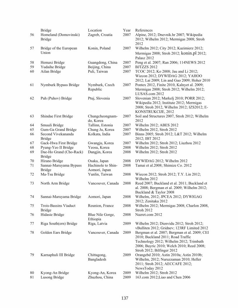
136
Bridge Location Year References 56 Homeland (Domovinski)
Bridge Zagreb, Croatia 2007 Alpine, 2012; Dnevnik.hr 2007; Wikipedia
2012; Wilhelm 2012; Mermigas 2008; Stroh 2012
57 Bridge of the European Union
Konin, Poland 2007 Wilhelm 2012; City 2012; Kazimierz 2012; Mermigas 2008; Stroh 2012; konin.pl 2012; Palasz 2012
58 Hemaxi Bridge Guangdong, China 2007 Peng et al. 2007; Ran 2006; 114NEWS 2012 59 Yudaihe Bridge Beijing, China 2007 BJTZZS 2012 60 Ailan Bridge Puli, Taiwan 2007 TCOC 2012; Ko 2008; Jau and Li 2012;
Wiecon 2012; DYWIDAG 2012; YAHOO 2012; Lai 2009; Lin and Guo 2009; Hoher 2010
61 Nymburk Bypass Bridge Nymburk, Czech Republic
2007 Pontex 2012, Finite 2010, Kalnyet al. 2009; Mermigas 2008; Stroh 2012; Wilhelm 2012; LUSAS.com 2012
62 Puh (Puhov) Bridge Ptuj, Slovenia 2007 Slovenian 2012; Markelj 2010; PORR 2012; Wikipedia 2012; Institute 2012; Mermigas 2008; Stroh 2012, Wilhelm 2012; IZS2012; E-KONSTRUKCIJE, 2012
63 Shindae First Bridge Chungcheongnam-do, Korea
2007 Soil and Structures 2007, Stroh 2012; Wilhelm 2012
64 Smuuli Bridge Tallinn, Estonia 2007 Wilhelm 2012; ABES 2012 65 Gum-Ga Grand Bridge Chung Ju, Korea 2007 Wilhelm 2012, Stroh 2012 66 Second Vivekananda
Bridge Kolkata, India 2007 Binns 2005; Stroh 2012; L&T 2012; Wilhelm
2012; IBT 2012 67 Gack-Hwa First Bridge Gwangju, Korea 2007 Wilhelm 2012; Stroh 2012; Liuzhou 2012 68 Pyung-Yeo II Bridge Yeosu, Korea 2008 Wilhelm 2012; Stroh 2012 69 Dae-Ho Grand (Cho-Rack)
Bridge Dangjin, Korea 2008 Wilhelm 2012; Stroh 2012
70 Hirano Bridge Osaka, Japan 2008 DYWIDAG 2012; Wilhelm 2012 71 Sannai-Maruyama Bypass
Bridge Hachinole to Shin-Aomori, Japan
2008 Tamai et al.2008; Shimize Co. 2012
72 Ma-Tsu Bridge Yunlin, Taiwan 2008 Wiecon 2012; Stroh 2012; T.Y. Lin 2012; Wilhelm 2012
73 North Arm Bridge Vancouver, Canada 2008 Reed 2007; Buckland et al. 2011; Buckland et al. 2008; Bergman et al. 2009; Wilhelm 2012; Buckland & Taylor 2008
74 Sannai-Maruyama Bridge Aomori, Japan 2008 Wilhelm, 2012; JPCEA 2012; DYWIGAG 2012; Zenitaka 2012
75 Trois-Bassins Viaduct Bridge
Reunion, France 2008 Wilhelm 2012; Mermigas 2008; Charlon 2008, Stroh 2012
76 Hidasie Bridge Blue Nile Gorge, Ethiopia
2008 Nazret.com 2012
77 Riga South(ern) Bridge Riga, Latvia 2009 Wilhelm 2012; Dienvidu 2012; Stroh 2012; vBulliten 2012; Gridnev; 123RF Limited 2012
78 Golden Ears Bridge Vancouver, Canada 2009 Bergman et al. 2007; Bergman et al. 2009; CEI 2010; Buckland 2011; Road Traffic Technology 2012; Wilhelm 2012; Trimbath 2006; Buyric 2010; Welch 2010; Reed 2008; Stroh 2012; Bilfinger 2012
79 Karnaphuli III Bridge Chittagong, Bangladesh
2009 Orangebd 2010; Astin 2010a; Astin 2010b; Wilhelm, 2012; Nuruzzaman 2010; Heller 2011; Stroh 2012; AECCAFE 2012; NewsToday 2012
80 Kyong-An Bridge Kyong-An, Korea 2009 Wilhelm 2012; Stroh 2012 81 Lusong Bridge Zhuzhou, China 2009 163.com 2012;Liao and Chen 2006
137

137
Bridge Location Year References 82 Xianshen River Bridge Shanxi, China 2009 Wilhelm 2012; CNKI 2012; Baidu 2012; Tang
and Chen 2009; Sina.com.cn 83 Ankang Qiligou Bridge Shanxi, China 2009 Baidu 2012; RBTMM.com; ChnRoad.com
2008 84 Incheon Bridge Incheon, Korea 2009 Park et al. 85 Qishan Bridge Gaoxiong, Taiwan 2010 TaiwanToday 2012 86 Choqueyapu Bridge La Paz, Bolivia 2010 Wilhelm 2012; Sobrino 2011; Skyscraper 2012;
Stroh 2012; QLJG8.com 2012 87 Kantutani Bridge La Paz, Bolivia 2010 Wilhelm 2012; Sobrino 2011; Skyscraper 2012;
Stroh 2012; QLJG8.com 2012 88 Orkojahuira Bridge La Paz, Bolivia 2010 Wilhelm 2012; Sobrino 2011; Skyscraper 2012;
Stroh 2012; QLJG8.com 2012 89 Povazska Bystrica D1
Motorway Viaduct Povazska Bystrica, Slovakia
2010 Wilhelm 2012; Strasky et al. 2011; Strasky 2010; Strasky 2012; Matascik 2012; Racansky 2012; Stroh 2012; SHP.ED 2012
90 Teror Viaduct Gran Canaria Island, Spain
2010 Wilhelm 2012’ Eispa 2012; Skyscraper 2012; bandadeteror.com 2012; abc.es 2012
91 New Amarube Bridge Japan 2010 Wikipedia 2012, Niwa 2010 92 Immobility Bridge Japan 2011 Wikipedia 2012, Go.JP 2012 93 Un-am Grand Bridge Jeonbuk, Korea 2011 Wilhelm 2012 94 Panyu Shanwan Bridge Guangzhou, China 2011 RBSCE.com 2012; Liu and Zheng 2007; Xuang
and Yang 2009 95 Jiayue (Nanping) Bridge Chongqing, China 2011 Baidu 2012; CNBridge 2012; Gov.cn 2010;
Qiaoliangren.net 2012 96 Tisza Bridge More Ferenc,
Hungary 2011 Pont-Terv 2012; Matyassy 2010; Torok 2011
97 Hwangdo Grand Bridge Changgi-ri, Korea 2011 BBG.CO.KR 2012 98 Nokan Bridge Busan, Korea 2011 DM Engineering Co. Ltd. 2012 99 Guemgang I Bridge Sejong City, Korea 2012 Wilhelm 2012; Naver.com 2012(122);
Leonhardt 2012; 100 Qinxiu Bridge Lugu, Taiwan 2012 TaiwanToday.com 2012; 101 Hualiantai Fengping
Bridge Hualian, Taiwan 2012 Yahoo.com 2012
102 Dazhihe Bridge Shanghai, China 2012 Tumukeji.com 2012; SHSZ.ORG.CN 2012 103 Najin Bridge Tibet, China 2012 Wilhelm 2012; News.CN 2010;
Chinatibetnews.com 2012, CCTV.com 2012 104 La Massana Bridge La Massana,
Andorra 2012 Wilhelm 2012; Rowson 2012; Stroh 2012
105 Naluchi Bridge Muzaffarabad, Pakistan
2012 Wilhelm 2012; Nagash 2012; Ghulam 2012; TOPIX.COM 2012; AEC-INC.JP 2012; GRC.COM.PK 2012
106 Waschmuhl Viauct Kreos, Germany 2012 Wilhelm 2012; Landesbetrieb 2012; LBM.RLP.DE 2012
107 New Pearl Harbor Memorial (Quinnipiac) Bridge
New Haven, US 2012 Wilhelm 2012; Dunham et al. 2010; Buckland 2012(20); Shane et al. 2012; Wikipedia 2012; Stroh 2012; CTDOT 2012; B-T.com 2012; Anderson 2011; i95newhaven.com 2012
108 Changshan Bridge Daliang, China 2013 EEmap.org 2012; Tumukeji.com 2012; News.lnd.com.cn 2012
109 Ningjiang Shonghuajiang Bridge
Jilin, China 2013 Zhao et al. 2010; Cr13g-lc.com 2011; rbtmm.com 2012
110 Halfsky Overpass Bridge Lugu, Taiwan 2013 Nantou.gov.tw 2012; LibertyTimes.com 2012; Myaena.net 2012
111 Yongjin Bridge Sang-ri, Korea 2014 BNG.CO.KR 2012 112 Gangchon 2nd Bridge Banggok-ri, Korea 2014 BNG.CO.KR 2012
138

138
Bridge Location Year References 113 Saint Croix River Bridge Houlton/Still
Water, United States
2014 Brinckerhoff 2010; URS 2012; Wilhelm 2012; Vineyard 2010; Minnesota 2012; Brinckerhoff 2012; PBS&J 2006
114 Sanguanjiang Bridge Wuhan, China 2015 163.com 2012; people.com.cn 2012; autohome.com.cn 2012
115 Brazos River Bridge Waco, United States
2015 McGowan 2011; Moore 2012; Finley 2012; TxDOT 2011; TxDOT 2012; Lane 2012; Adesanya 2012; Yogi 2012; Wood 2012; 1000 Friends of Waco 2012
116 Naericheon Bridge Sangnam Inje Kangwon, Korea
2015 DM Engineering Co. Ltd. 2012
117 Yaro Grand Bridge Yaro myun, Korea 2015 Naver 2012 118 Pyung-Taik Grand Bridge Pyung-Taik City,
Korea 2016 Naver 2012
119 Beixi Hechuan Bridge Nanao, Taiwan 2016 Ceci.com.tw 2012 120 Kinmen Bridge Kinmen, Taiwan 2016 Wantchinatimes.com 2012
139

140

139
APPENDIX B: SUMMARY OF EXTRADOSED BRIDGES
Name Country
Year Built (Construction Duration, mth)
Span Lengths (ft) Tower Height (ft) (#)
Girder Depth (ft) x Width (ft)
Girder Description
Picture Drawings
1 Odawara Blueway Bridge (小田原ブルーウェイブ
リッジ, 小田原港橋) Japan
1994 (35)
243+433+243 35.1 (2x2)
(7.2-11.5)x42.7 Wide double cell concrete
box girder
2 Tsukuhara Bridge (つくはら橋, 佐敷大橋)
Japan 1997 (36)
217+519+253 52.5 (2x2x2)
(9.8-18.0)x42.0 Wide single cell concrete box girder. Two separate
bounds.
3 Yashiro Bridge (屋代橋)
Japan 1997
213+344+344+213 (S) 180+295+180 (N)
39.4 (2x3, S) 32.8 (2x2, N) -
Concrete box girder
141

140
4 Kanisawa Bridge
(蟹沢大橋) Japan 1998
326+591+326 72.5 (2x2)
(10.8-18.4)x57.4 Concrete box girder
5 Shin-Karato (Okuyama) Bridge (唐櫃新橋)
Japan 1998
217+394+236 (E) 243+459+227 (W)
39.4 (2x2 Both bounds) (8.2-11.5)x31.8 (E) (8.2-11.5)x41.5 (W)
Two and three cell concrete box girder
(West Bound) 6 Sunniberg Bridge
Switzerland 1998 (30)
194+420+459+440+213 48.6 (4x2) 3.6x40.6
Concrete slab with edge stiffening beams
7 Mitanigawa Bridge (Santanigawa Bridge)
Japan 1999
190+305 41.3 (1x1)
(8.2-21.3)x66.9 Double cell concrete box
girder
142

141
8 Sapporo Railway Bridge (新川高架桥)
Japan 1999 (27)
182+182 32.5 (1x2)
NA Continuous prestressed
concrete bridge
9 Second Mactan–Mandaue Bridge
Philippines 1999 (27)
366+607+366 59.1 (2x2)
(10.8-16.7)x59.1 Three cell concrete box
girder
10 Pont de Saint-Rémy-de-Maurienne Bridge
France 1999
172+159 19.4 (1x2) 7.1x44.0
U-shape concrete girder with transverse ribs between
edge beams
11 King Hussein Bridge Jordan 1999
112+171+112 -(2x2)
(4.9-8.2)x62.0 Three cell concrete box
girder
12 Pakse Bridge Laos and Thailand
2000
404+469+300 49.2 (2x2)
(9.8-21.3)x45.3 Single cell concrete box
girder
143

142
13 Sajiki Bridge (佐敖大桥) Japan 2000
201+344+191 38.5 (2x2)
(6.9-10.5)x36.1 Concrete box girder
14 Shikari Bridge (土狩大橋)
Japan 2000
308+459+459+459+308 32.8 (4x1)
(9.8-19.7)x92.1 Concrete box girder
15 Surikamigawa Bridge Japan 2000
278 54.1
(9.2-16.4)x30.2 Concrete box girder
16 Wuhu Yangtze River Bridge (芜湖长江大桥)
China 2002 (42)
591+1024+591 114.8 (2x2) 44.3x76.8
Double-girderer steel truss with composite girder slab on top roadway, two rail
lines on bottom level.
17 Yukizawa Bridge (雪沢大橋)
Japan 2000
231+233 37.7 (2x2)
(6.6-11.5)x51.8 Two cell concrete box girder
144
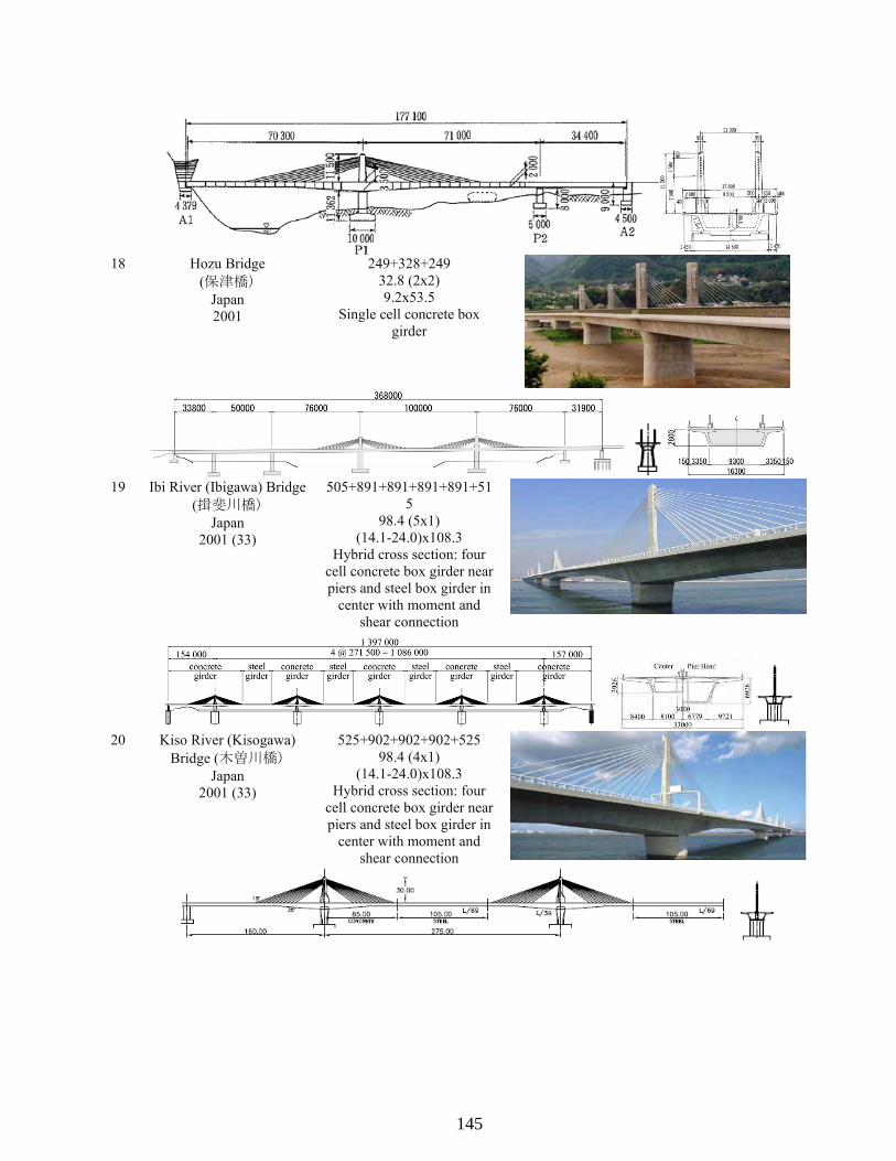
143
18 Hozu Bridge (保津橋)
Japan 2001
249+328+249 32.8 (2x2) 9.2x53.5
Single cell concrete box girder
19 Ibi River (Ibigawa) Bridge (揖斐川橋)
Japan 2001 (33)
505+891+891+891+891+515
98.4 (5x1) (14.1-24.0)x108.3
Hybrid cross section: four cell concrete box girder near piers and steel box girder in
center with moment and shear connection
20 Kiso River (Kisogawa) Bridge (木曽川橋)
Japan 2001 (33)
525+902+902+902+525 98.4 (4x1)
(14.1-24.0)x108.3 Hybrid cross section: four
cell concrete box girder near piers and steel box girder in
center with moment and shear connection
145

144
21 Miyakoda (Miyakodagawa) River
Bridge (都田川橋) Japan
2001 (55)
440+440 65.6 (1x3)
(13.1-21.3)x65.3 Parallel double cell concrete
box girder
22 Nakanoike Bridge Japan 2001
199+199 38.7
(8.2-13.1)x70.2
23 Zhangzhou Zhanbei Bridge (漳州战备大桥)
China 2001 (17)
265+433+265 54.1 (2x1)
(7.9-12.5)x88.6 Three cell concrete box
girder
24 Fukaura Bridge (長者ヶ橋)
Japan 2002
204+293+217+148+96 27.9
(8.2-9.8)x44.9
25 Koror-Babeldaob (Japan-Palau Friendship) Bridge
Palua 2002 (60)
269+810+269 97.3 (2x2)
(11.5-23.0)x38.1 Hybrid cross section: wide single concrete box girder near piers and steel box
girder in central.
26 Sashikubo Bridge
Japan 2002
374+374 72.2 (1x2)
(10.5-21.3)x37.1 Concrete box girder
146

145
27 Shinkawa (Tobiuo) Bridge (とびうお大橋,
新川大桥) Japan 2002
295+427+264 42.7 (2x1)
(7.9-13.1)x84.6 Three cell concrete box
girder
28 Tongan Yinhu Bridge
(同安银湖大桥) China 2002
262.5+262.5 103.3 (1x1)
(7.9-12.5)x88.6 Three cell concrete box
girder
29 Changcheng Yunhe Bridge (常澄路京杭运河特大桥)
China 2003 (15)
230+394+230 101.7 (2x2)
(8.5-13.5)x91.9 Three cell concrete girder
box
30 Deba River Bridge Spain 2003
138+217+138 39.0 (2x2)
(8.9-8.9)x45.6 U shaped concrete girder
with transverse ribs between edge beams
31 Xiaoxihu Yellow River Bridge (小西湖黄河大桥)
China 2003 (22)
266+446+266 55.8 (2x2)
(8.5-14.8)x88.6 Three cell concrete girder
box
147

146
32 Shanxi Fenhe Bridge (山西汾河大桥)
China 2003
295+492+295 118.1 (2x3) NAx85.3
33 JR Arakogawa Bridge (JR荒子川橋梁)
Japan 2003 (15)
178+295+185 29.5 (2x2) 8.5x41.7
Concrete box girder
34 Himi Bridge (日見夢大橋)
Japan 2004
301+591+301 65 (2x2)
13.1x40.8 Single cell doubly
composite box girder with corrugated steel webs
35 Korong Bridge Hungary
2004
172+203 31.0 (1x2) 8.2x52.0
Three cell concrete box girder stiffened with
transverse ribs
148

147
36 Tatekoshi (Matakina) Bridge Japan 2004
185+185 34.4 (1x2)
(5.9-9.5)x62.8 Concrete box girder
37 Shin-Meisei Bridge (赤とんぼ橋)
Japan 2004
290+401+266 54.1 (2x1) 11.5x62.3
Three cell concrete trapezoidal box girder.
38 Yinchuan Beierhuan I Bridge
(银川市北二环路一号桥) China
2004 (25)
230+230 95.1 (1x2) 7.9x196.2
Wide four cell concrete box girder
39 Shuqian Nanerhuan Bridge (宿迁南京路运河大桥)
China 2005 (24)
217+361+217 45.9 (2x1)
(7.2-11.5)x65.6 Three cell concrete box
girder
149

148
40 Brazil-Peru Integration Bridge
Brazil/Peru 2005
213+361+213 49.2 (2x2)
(7.1-11.0)x55.1 Wide single cell concrete
box girder
41 Sannohe-Boukyo Bridge (三戸望郷大橋)
Japan 2005
328+656+328 82.0 (2x2)
(11.5-21.3)x44.1 Two cell concrete box girder
42 Lishi Gaojia Bridge (离石高架桥)
China 2005
279+443+279 59.1 (2x1)
(7.9-13.8)x85.3 Three cell concrete box
girder
43 Yinchuan Lixinglu I Bridge
(银川丽兴路一号桥) China 2006
- 94.5
-x196.8 Two cell concrete box girder
150
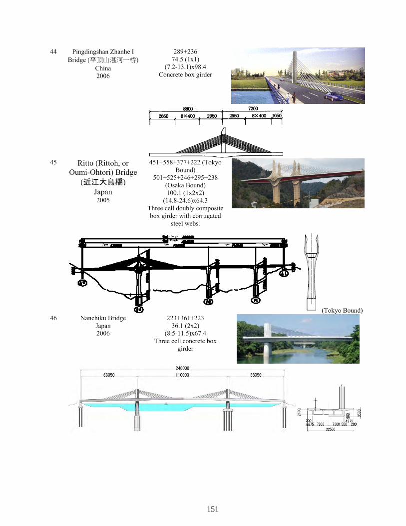
149
44 Pingdingshan Zhanhe I Bridge (平顶山湛河一桥)
China 2006
289+236 74.5 (1x1)
(7.2-13.1)x98.4 Concrete box girder
45 Ritto (Rittoh, or Oumi-Ohtori) Bridge
(近江大鳥橋) Japan 2005
451+558+377+222 (Tokyo Bound)
501+525+246+295+238 (Osaka Bound) 100.1 (1x2x2)
(14.8-24.6)x64.3 Three cell doubly composite box girder with corrugated
steel webs.
(Tokyo Bound) 46 Nanchiku Bridge
Japan 2006
223+361+223 36.1 (2x2)
(8.5-11.5)x67.4 Three cell concrete box
girder
151

150
47 Rio Branco Third Bridge Brazil 2006
177+295+177 39.7 (2x2)
(6.6-8.2)x69.2 Girder slab with L-shape edge beams (appears as single box girder with
incomplete bottom slab) that taper to I beams at midspan.
48 Liuzhou Sanmenjiang Bridge (柳州三门江大桥)
China 2006 (25)
328+525+328 72.2 (2x2)
(8.2-22)x134 Separated concrete box
girder, two cell on each side.
49 Tagami Bridge Japan 2006
263+263 47.6
(9.8-14.8)x58.4
50 Tokunoyamahattoku Bridge (徳之山八徳橋)
Japan 2006 (22)
458+722+458 73.8 (2x2)
(11.5-21.3)x31.5 Single cell concrete box
girder
152

151
51 Yanagawa Bridge Japan
2006 (34)
429+429 78.7 (1x2)
(13.1-21.3)x57.1 Two cell concrete box girder
52 Huiqing Huanghe Bridge (惠青黄河大桥)
China 2006 (32)
436+722+439 99.4 (2x1)
(13.1-24.6)x65.6 Three cell concrete box
girder
53 Kaifeng Huanghe II Bridge (开封黄河二桥)
China 2006 (26)
279+6x459+279 118.1 (7x2)
-x98.4
54 Fuzhou Pushang Bridge (福州浦上大桥)
China 2006 (28)
236+361+361+236 88.6 (3x2)
-x109.9
55 Chaobaihe Bridge (京承高速潮白河大桥)
China 2006
236+394+394+236 70.5 (3x1)
(7.2-13.8)x96.8 Three cell concrete girder
153

152
56 Homeland (Domovinski) Bridge Croatia 2007
236+394+236 54.1 (2x2) 11.6x109.9
Five cell concrete box girder supported light rail between
cable planes
57 Bridge of the European Union Poland 2007
197+262+197 33.8 (2x2)
-x82.3
58 Hemaxi Bridge (荷麻溪大桥)
China 2007
410+755+410 128
(9.8-21.3)x92.8 Three cell concrete box
girder
59 Yudaihe Bridge
(玉带河大桥) China 2007
148+279+279+148 92.2 (3x2)
-x109.9
60 Ailan Bridge (國道六號愛蘭橋)
Taiwan 2007
262+459+262 65.6 (2x1)
(9.8-16.7)x85.1 Multi-cell concrete box
girder.
154

153
61 Nymburk Bypass Bridge Czech 2007
135+443+135 52.5 (2x2) (7.5-)x54.6
Composite steel-concrete structure built into the ends
of the concrete structure.
62 Puh (Puhov) Bridge Slovenia 2007 (19)
231+328+328+328+213 27.9 (6x3) 8.9x61.4
Single cell concrete box girder
63 Shindae Bridge Korea 2007
148+256+256+148 39.4
-x70.8
64 Smuuli Bridge Estonia
2007
138+279+138 - (2x2)
- Concrete box girder
65 Gum-Ga Grand (Kumga) Bridge Korea 2007
85.35+125+125+125+125+125+85.25 8.85 (6x2)
-x23 Multiple cell concrete box
girder
66 Second Vivekananda Bridge India 2007
180+7x361+180 45.9 (8x2) 11.2x95.1
Concrete box girder
155

154
67 Gack-Hwa First Bridge Korea
2007 (33)
377+328 75.5 (1x2)
(11.6-16.3x10² Multiple cell concrete box
girder
68 Pyung-Yeo II Bridge
Korea 2008
213+394+213 34.4 (2x2)
(11.5-13.1)x68.9 Four cell concrete box
girder
69 Dae-Ho Grand (Cho-Rack) Bridge Korea 2008
230+427+427+427+230 54.1 (4x2)
(8.2-11.5)x45.19 Two cell concrete box girder
70 Hirano Bridge Japan 2008
207 (main span) - -
Concrete box girder
156

155
71 Sannai-Maruyama Bypass Bridge (三内丸高架桥)
Japan 2008 (36)
246+492+492+246 - (3x2)
- Two cell concrete box
girder.
72 Ma-Tsu Bridge (媽祖大橋)
Taiwan 2008
410+410 114.8 (1x1)
(8.2-19.7)x88.6 Concrete box girder
73 North Arm (Canada Line Extradosed Transit) Bridge
Canada 2008
456+591+456 59.1 (2x1)
(9.2-19.0)x33.8 Single cell concrete box
girder
74 Sannai-Maruyama Bridge Japan 2008
243+492+492+243 57.4 (3x2)
(12.5-24.2)x45.4 Four cell concrete box
girder
157

156
75 Trois-Bassins Viaduct Bridge France
2008 (33)
413+343+248 32.8 & 62.3 (1x1 &1x1)
(13.1-23.0)x72.2 Single cell concrete box girder with steel struts supporting long girder
cantilevers.
76 Hidasie Bridge Ethiopia
2008
476 (994 Total) -(2x2)
77 Riga South(ern) Bridge Latvia
2008 (48)
361 (main) 43.7 (6x1)
-x112.5
78 Golden Ear Bridge Canada
2009
397+794+794+794+397 136.2 (4x2)
(8.9-14.8)x105.0 Steel box girders at edge of girder with transverse floor
beams composite with precast concrete girder.
79 Karnaphuli III (Shah Amanat) Bridge
Bangladesh 2009
377+656x3+377 84.5 (4x1)
(13.1-22.1)x80.3 Single cell concrete box
girder
158
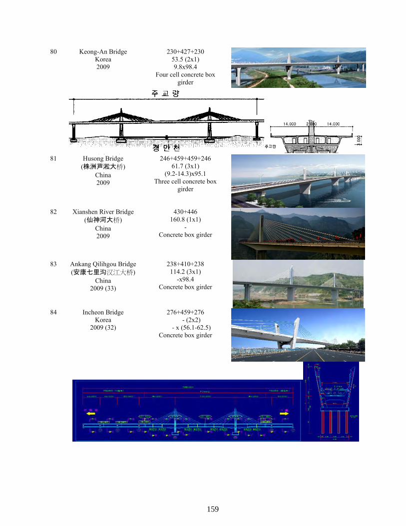
157
80 Keong-An Bridge Korea 2009
230+427+230 53.5 (2x1) 9.8x98.4
Four cell concrete box girder
81 Husong Bridge (株洲芦淞大桥)
China 2009
246+459+459+246 61.7 (3x1)
(9.2-14.3)x95.1 Three cell concrete box
girder
82 Xianshen River Bridge (仙神河大桥)
China 2009
430+446 160.8 (1x1)
- Concrete box girder
83 Ankang Qilihgou Bridge (安康七里沟汉江大桥)
China 2009 (33)
238+410+238 114.2 (3x1)
-x98.4 Concrete box girder
84 Incheon Bridge Korea
2009 (32)
276+459+276 - (2x2)
- x (56.1-62.5) Concrete box girder
159
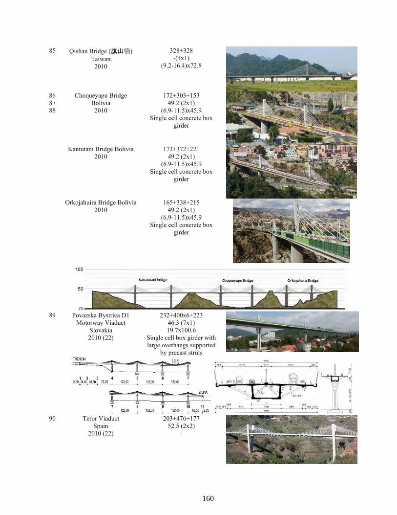
158
85 Qishan Bridge (旗山橋) Taiwan
2010
328+328 -(1x1)
(9.2-16.4)x72.8
86 87 88
Choqueyapu Bridge Bolivia 2010
172+303+153 49.2 (2x1)
(6.9-11.5)x45.9 Single cell concrete box
girder
Kantutani Bridge Bolivia 2010
173+372+221 49.2 (2x1)
(6.9-11.5)x45.9 Single cell concrete box
girder
Orkojahuira Bridge Bolivia 2010
165+338+215 49.2 (2x1)
(6.9-11.5)x45.9 Single cell concrete box
girder
89 Povazska Bystrica D1 Motorway Viaduct
Slovakia 2010 (22)
232+400x6+223 46.3 (7x1) 19.7x100.6
Single cell box girder with large overhangs supported
by precast struts
90 Teror Viaduct Spain
2010 (22)
203+476+177 52.5 (2x2)
-
160

159
91 New Amarube Bridge 余部橋梁(新橋梁)
Japan 2010
164+271+271+180 16.5 (3x2) 11.5x23.8
Single cell concrete box girder
92 Immobility Bridge 不動大橋
Japan 2011 (84)
410+509+509+290 -(3x2) -x42.7
Single cell concrete box girder
93 Un-am Grand Bridge Korea
2011 (86)
246+427x4+246 26.2 (5x1)
(10.8-13.5)x75.5 Concrete box girder
94 Panyu Shawan Bridge (番禺沙湾大桥)
China 2011
451+814+451 123.0 (2x1)
(13.1-27.9)x111.5 Three cell concrete box
girder 95 Jiayue (Nanping) Bridge
(嘉陵江南屏大桥,
嘉悦大桥) China 2011
335+623+302 - (2x2) -x90.2
Concrete box girder
161

160
96 Tisza Bridge Hungary
2011
312+591+312 52.5 (2x1)
(13.1-19.7)x98.2 Three cell box girder with
corrugated steel web
97 Hwangdo Grand Bridge Korea
2011 (11)
262+459+262 45.9 (2x2)
(8.2-13.5)x47.2 Two cell concrete box girder
98 Noksan Bridge Korea 2011
230+230 -(1x1) -x73.3
Concrete box girder and orthotropic steel girder
girder 99 Guemgang I Bridge
Korea 2012 (52)
328+591x3+328 85.2 (4x2)
-x98.4 Three cell continuous
concrete beam
100 Qinxiu Bridge (鹿谷清秀橋)
Taiwan 2012
384 Total - (2x1) -x39.4
Concrete box girder
162

161
101 Hualiantai Fengping Bridge (花蓮縣豐平橋)
Taiwan 2012 (30)
276+459+459+276 55.8 (3x1)
(8.7-15.7)x92.5 Five cell concrete box girder
102 Dazhihe Bridge (上海大治河桥)
China 2012
262+459+262 67.3 (2x1)
- Concrete box girder
103 Najin Bridge (纳金大桥) China
2012 (22)
230+361+361+230 -(3x1) x108.3
Single cell concrete box girder
104 La Massana Bridge Andorra
2012
- -(1x2x2)
-
105 Naluchi Bridge Pakistan
2012 (33)
400+400 78.7 (1x2)
(11.5-23)x51.2 Concrete box girder
106 Waschmuhl Viauct Germany
2012
- - (2x2) -x62.8
163

162
107 New Pearl Harbor Memorial (Quinnipiac)
Bridge United States
2012/2015 (60)
249+515+249 69.9 (2x3)
(11.3-16.2)x110.6 Five cell concrete box girder
108 Changshan Bridge (长山大桥)
China 2013 (24)
459+853+459 84.5 (2x2)
-x75.5
109 Ningjiang Shonghuajiang Bridge
(宁江松花江特大桥) China
2013 (36)
312+3x492+312 - (4x1)
(9.8-18)x86.9 Three cell concrete box
girder
110 Halfsky Overpass Bridge (小半天高架橋)
Taiwan 2013 (20)
1214 (Total) -(2x1)
111 Yongjin Bridge Korea
2014 (18)
271+443+271 44.3 (2x2)
(8.2-14.8)x50.9 Three cell concrete box
girder
112 Gangchon 2nd Bridge Korea
2014 (32)
272+459+272 59.1 (2x2)
(9-16.4)x64.6 Three cell concrete box
girder
164
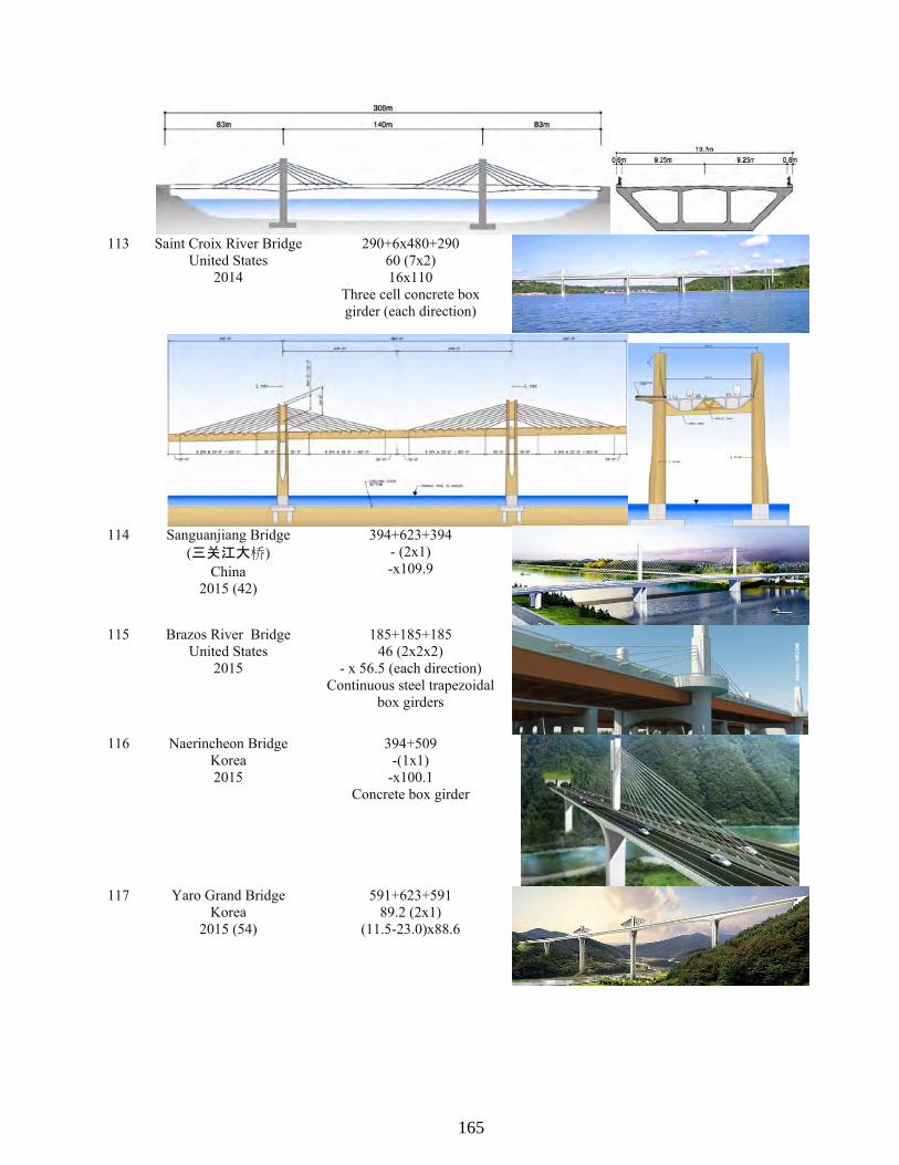
163
113 Saint Croix River Bridge United States
2014
290+6x480+290 60 (7x2) 16x110
Three cell concrete box girder (each direction)
114 Sanguanjiang Bridge (三关江大桥)
China 2015 (42)
394+623+394 - (2x1) -x109.9
115 Brazos River Bridge United States
2015
185+185+185 46 (2x2x2)
- x 56.5 (each direction) Continuous steel trapezoidal
box girders
116 Naerincheon Bridge Korea 2015
394+509 -(1x1)
-x100.1 Concrete box girder
117 Yaro Grand Bridge Korea
2015 (54)
591+623+591 89.2 (2x1)
(11.5-23.0)x88.6
165

164
118 Pyung-Taik Grand Bridge Korea
2016 (60)
361+525x6+295 67.3 (7x1)
(11.5-18)x98.1
119 Beixi Hechuan Bridge (南澳北溪河川橋)
Taiwan 2016
312+525+344 - (2x1)
120 Kinmen Bridge (金门大桥)
Taiwan 2016
919 (4593 Total) - (5x1)
166

165
APPENDIX C: INTERVIEW QUESTIONS AND RECORDS
Interview Questions
Research Questions Regarding Extradosed Bridge Dear XXXX, First of all, thanks for sharing the photos with us and thanks again for willing to participate in our research. As I mentioned earlier, the study is associate with Texas Department of Transportation Project 0-6729 (Synthesis on Cost Effectiveness of Extradosed Bridges). Since extradosed bridge is still a fairly new concept, there is not much information out there regarding extradosed bridge, practically to help making decision in selecting this kind of bridge. We are seeking inputs from personnel with experiences on extradosed bridges. Our record shows that you have been involving in the design and construction of XXXX Bridge and would like to receive your inputs regarding this bridges and general concept of extradosed bridge. Following are a series of questions related to the particular bridge and some general questions related to extradosed bridges. We are estimating that the whole set of questions will take approximately 15 to 20 minutes to complete. Should there be any question that you feel better to communicate through phone call, or any other comments that you would like to share we will be more than happy to do that as well. Your responds will be summarized and included in our project report and we will be more than happy to share it with you after we finalize the report, should you be interested. Once again, on behalf of the research team, I will like to thank you for your time and support on this research. Regards, Jiong Hu XXXX Bridge 1. Bridge Construction
a. What was the construction duration of the bridge? b. What was the construction method of the extradosed part of the bridge? What were the
major reasons that this method was used? c. Based on your experience, is there any challenge or advantage in adopting this
construction method during the construction of the bridge? 2. Reasons of selecting extradosed bridge
a. Can you list the major reasons that led to the decision of selecting extradosed design over other bridge designs (i.e., cable-stayed bridge and girder bridge)? Among them, what reason is the most critical one?
b. Among all the options during the bridge selection process, what type of bridge was the second best option for this case?
167

166
3. Cost of extradosed bridges construction (Please note that we understand that this information might be sensitive, we can have the information remain anonymous if you request so.)
a. What was the total cost of the bridge? What was the total cost of extradosed section of the bridge?
b. What was the proportion of the extradosed part (superstructure of the extradosed part, including labor, material, and so forth) of this bridge in the total cost?
c. What was the unit cost (in $/m2 or any other units that you are using)? d. Can you compare the cost this bridge to an alternate bridge type (the second best option
in this case)? e. Comparing to the alternate bridge type (the second best option in this case), what part(s)
of the extradosed bridge increased/decreased the total cost most? 4. Advantages and disadvantages of extradosed bridges.
a. Based on your experiences, what are the advantages of extradosed bridges? b. Based on your experiences, what are the disadvantages of extradosed bridges? c. Can you compare the following aspects of this bridge to an alternate bridge type (the
second best option of this case)? i. Cost effectiveness:
ii. Construction period and method: iii. Future maintenance and repair difficulties:
5. Maintenance and repair cost
a. Do you experience or expect higher or lower maintenance cost comparing to cable-stayed bridge, by how much percentage?
b. Do you experience or expect higher or lower maintenance cost comparing to girder bridge, by how much percentage?
c. Do you experience or expect higher or lower repair cost comparing to cable-stayed bridge, by how much percentage?
d. Do you experience or expect higher or lower repair cost comparing to girder bridge, by how much percentage?
e. Is there any special issue related to maintenance and repair of extradosed bridge (comparing to cable-stayed bridge and girder bridge)?
Should there be any question list above that is not clear or need clarification, please let me know.
168

167
Interview Record #1
Interviewee: Christopher Scollard Bridge Name: North Arm Bridge 1. Bridge Construction
a. Approximately 2 years. b. Balanced cantilever - that is the way these bridges are built. Other options are not
practical for bridges of moderate spans. c. Many challenges as there always are, but none related to this construction method being
chosen over another.
2. Reasons of selecting extradosed bridge a. The extradosed bridge was selected because it satisfied the span requirement and had
short pylons that were outside of the flight path leading up to the adjacent airport. b. No other options met the span requirements and were consistent with the precast
segmental system being used throughout the project, which was much larger than just the construction of the extradosed bridge.
3. Cost of extradosed bridges construction Insufficient information available to answer.
4. Advantages and disadvantages of extradosed bridges.
a. Moderate spans with short pylons and moderate superstructure weight. b. Heavier and with all the added complications of a cable-stayed bridge. c. i. Cost effectiveness: Unproven - cost effectiveness is not the primary driver for this type
of bridge; geometry is more influential; ii. Construction period and method: No real difference; iii. Future maintenance and repair difficulties: No real difference.
5. Maintenance and repair cost We don't have specific data to support answers to these questions, but don't expect
maintenance costs to be any higher than for other more common bridge types. Bridge Name: Golden Ears Bridge Answers for the North Arm Bridge are generally applicable to the Golden Ears Bridge. There are very few differences between this bridge and a more conventional cable-stayed bridge other than slightly shallower cable angles (and thus lower live load stress range in the cables) and a slightly deeper and stiffer superstructure. Construction period was longer than the North Arm Bridge because the bridge length is much longer.
Interview Record #2
Interviewee: Akio Kasuga Bridge Name: Odawara Blueway Bridge
169
168
1. Bridge Construction
a. 1992/12 to 1994/10 b. Free cantilevering method.
Most economical method for the bridge over the port. c. Free cantilevering method for extradosed bridges is the same as conventional one.
2. Reasons of selecting extradosed bridge a. Major reason is the cost. And another reason is aesthetics for harbor bridge. b. Conventional box girder bridge.
3. Cost of extradosed bridges construction a. Total cost : 2.4 Billion JY, Superstructure : 1.5 Billion JY b. 63% c. 390,000 JY/m2 (superstructure) d. No information e. Cheaper substructure cost because of lighter superstructure.
4. Advantages and disadvantages of extradosed bridges. a. Easy construction (No stay cable force adjustment during construction, easy camber
control due to stiffer girder, cheaper stay cable system because of low fatigue stress due to live load)
b. Shorter tower sometimes leads difficulties of elegant design of tower and pier. c. i. Cost effectiveness: Cheaper;
ii. Construction period and method: A little bit longer because of stay cable construction; iii. Future maintenance and repair difficulties: Maintenance and possibility of stay cable replacement are added.
5. Maintenance and repair cost a. I think the maintenance cost is almost the same as CSB. In Odawara Buleway bridge, we
did the detail inspection once for extradosed cables. One lane was shut down during the night inspection. (One tower and one side took one night. Totally four nights)
b. No information of percentage. c. I think the maintenance cost is higher than girder bridge because of extradosed cables. No
information of percentage. d. No experience and information. e. I think there is no special issue.
Bridge Name: Tsukuhara Bridge 1. Bridge Construction
a. 1994/12 to 1998/7 b. Free cantilevering method.
Most economical method for the bridge over the lake. c. Free cantilevering method for extradosed bridges is the same as conventional one.
2. Reasons of selecting extradosed bridge
170

169
See Odawara Blueway Bridge 3. Cost of extradosed bridges construction
a. Total cost : 6.5 Billion JY, Superstructure : 3.4 Billion JY b. 53% c. 573,000 JY/m2 (superstructure) d. No information e. Cheaper substructure cost because of lighter superstructure.
4. Advantages and disadvantages of extradosed bridges.
See Odawara Blueway Bridge 5. Maintenance and repair cost
See Odawara Blueway Bridge. But we have not inspected extradosed cables of Tsukuhara Bridge yet. Bridge Name: Ibi River Bridge 1. Bridge Construction
a. 1997/3 to 2001/7 b. Free cantilevering method using 400 tons precast segments. 100m center part is steel
girder constructed by lifting method. Most economical method for the bridge over the mouth of the wide river.
c. First application of 400-ton heavy segments. Extradosed with composite girder (100m center part is steel box girder.)
2. Reasons of selecting extradosed bridge
See Odawara Blueway Bridge 3. Cost of extradosed bridges construction
a. Total cost : 83.7 Billion JY, Superstructure : 63.0 Billion JY (This cost includes Ibi and Kiso River bridge. Kiso Bridge is 5-span type. Structure is the same as Ibi River Bridge.)
b. 75% c. 780,000 JY/m2 (superstructure) d. No information e. Cheaper substructure cost because of lighter superstructure.
4. Advantages and disadvantages of extradosed bridges.
See Odawara Blueway Bridge 5. Maintenance and repair cost
See Odawara Blueway Bridge
Interview Record #3
Interviewee: Deong-Hwan Park Bridge Name: NA
171

170
1. Bridge Construction
a. In general, the construction duration of the ED Bridge is similar to the duration of PSC Box bridge added the duration of its main tower on the bridge; construction period for main tower per each is 3 to 5 months, in case of Free Cantilever Method (FCM), the duration of substructure is 1 to 2 months, and each segment which is upper girder is about 20days. (일반적으로 PSC BOX교량의 공기와 비슷하며 주탑시공기간이 추가됨 공사기간은 주탑시공(기당) 3~5개월, 주두부(FCM공법 적용시) 1~2개월, 상부시공(Seg 당) 20일 정도임.)
b. The construction method of ED Bridge is depended on site conditions which are the types of foundations, substructures, and span length. Typically FCM method would be used at ED Bridge for crossing the river and long span at sea bridge.( ED교는 하부시공조건에 따라 시공방법이 다르나, 일반적으로 하천횡단이나 해상교량에 적용되는 장경간 교량으로 FCM공법을 많이 적용함)
c. It would be able to use for curved bridge. Also, when Form traveler can be applied for the construction, it will improve the constructability and come out better quality of material management by the repetitive task without site conditions under the bridge. (하부 조건에 구애받지 않고 곡선교량에 적용 가능하며, F/T를 이용한 반복작업으로 시공성이 좋고 재료의 품질관리가 양호함.)
2. Reasons of selecting extradosed bridge a. As you know, since cable-stayed bridge has to support the main structures using the
cable, the load imposed on the plate girder is relatively smaller than PSC Box bridge. To ensure the stiffness of the cable, the height of the tower would be enhanced. Therefore, economic feasibility and constructability is not as good as its ED Bridge. In addition, cable stayed bridge is vulnerable to the dynamic behavior due to the low structural rigidity. On the other hand, ED bridge is supported by both girder and cable with lower tower so it has much better structural rigidity and excellent dynamic behavior compared with cable stayed bridge. (사장교는 말 그대로 케이블이 주 지지구조물로 보강형이 지지하는 하중의 비율이 작음. 따라서 케이블의 강성확보를 위해 주탑의 높이가 높아져야 하고 이로인한 시공성, 경제성이 ED교에 비해 좋지 않으며, 구조적으로 강성이 크지 않아 동적거동에 취약한 측면이 있음. 반면 ED교의 경우, 주형과 케이블이 함께 지지하는 구조물로 주탑이 높지 않아도 되고, 강성이 커 사장교에 비해 동적거동이 우수함.)
b. PSC BOX Bridge and Cable Stayed Bridge (PSC BOX 교, 사장교)
3. Cost of extradosed bridges construction
a. Not sure exact number because detailed construction cost must include design cost as well. The unit construction cost, including sub, superstructure and main tower, of the ED Bridges that have already built is about $465 to $511 per ft2. (currency rate 1 dollar = 1000 won) (구체적인 공사비는 설계를 통해야 하고, 현재 시공된 ED교의 면적당 공사비(상,하부 포함)는 500~550만원 정도임.)
172

171
b. It varies, but the construction cost of superstructure is about 75 to 80% of total construction cost depending on site condition. (총 공사비중 상부공사비는 약 75~80% 정도로 보이나 하부조건에 따라 틀리므로 정확한 수치를 알수는 없음.)
c. See above “a” (위 a 참조) d. It varies, but in case of PSC BOX Bridge, The unit construction cost, including sub,
superstructure and main tower, applied FCM is about $372 to $418 per ft2. (PSC BOX교의 경우, 시공방법에 따라 차이가 있으나 FCM공법 적용시 면적당 공사비(상,하부 포함)는 보통400~450만원 정도임.) It is varies due to different types of materials such as steel, concrete, and composite bridge, but the unit construction cost of Concrete Cable stayed bridge is $697 per ft2. (사장교의 경우는 재료(강, 콘크리트, 복합구조 등)에 따라 다르며 콘크리트 사장교의 경우는 면적당 750만원 정도임.)
e. Since ED Bridge has main tower, ED Bridge has longer span than PSC BOX bridge so that ED Bridge is lower construction cost of substructure. However ED bridge gets much bigger eccentricity than its PSC BOX bridge so ED Bridge uses more strands that increase construction cost than PSC BOX bridge. Finally, overall construction cost of ED Bridge is little more. The construction cost of cable stayed bridge is very expensive due to the cable and main tower. (PSC BOX교의 경우, ED교는 주탑이 추가되므로 하부 공사비가 적으며 또한 ED교는 대편심교량으로 텐던(강연선)량이 PSC BOX교보다 다소 많음 따라서 PSC BOX교의 공사비가 저렴하며, 사장교는 케이블과 주탑공사비로 인해 공사비가 고가임.)
4. Advantages and disadvantages of extradosed bridges. a. It can be possible to make the long span with low price compared to cable-stayed bridge
and can be secured due to the higher stiffness of the bridge. (저렴한 가격(사장교에 비해)으로 장대교량 적용이 가능하며, 교량강성이 커 안전성 확보가 우수함.)
b. Since the installation of Cable outside would be dropped the constructability and brought out safety issues, it has disadvantages over PSC BOX bridge. (당연히 외부에 설치되는 케이블의 시공성과 안전성(케이블의 부가응력 등)이 일반 PSC BOX교 보다 불리함.)
c. i. Cost effectiveness: See previous answers (위의 내용들로 대체); ii. Construction period and method: See previous answers (위의 내용들로 대체); iii. Future maintenance and repair difficulties: In the Maintenance and repair PSC Box, ED Bridge, and Cable –stayed Bridge is advantageous in order due to the cable and fatigue at the anchorage (유지관리차원에서는 PSC BOX > ED교 > 사장교 순으로 유리하며, 이유는 외부 케이블 및 정착부 피로 등에 대한 유지관리 측면에서 외부 케이블이 있는 교량이 불리함.).
5. Maintenance and repair cost It would be difficult that the maintenance aspect can be expressed as a certain portion of
total project (budget).
(유지관리 측면을 비율로 나타내기는 좀 어려울 듯) a. N/A
173

172
b. N/A c. N/A d. N/A e. I think it would be fatigue problem (역시 피로에 대한 부분이 아닐까 생각됨.)
Interview Record #4
Interviewee: Sun-Joo Choi Bridge: Guemgang 1st Bridge 1. Bridge Construction
a. 5 Years (5년) b. Free Cantilever Methods, Because the bridge cross the river (F.C.M, 하천를 횡단하기 때문에)
c. N/A 2. Reasons of selecting extradosed bridge
a. Construction method, Environment, Construction cost, Aesthetics, Etc... The most important factor among all motioned above was aesthetic. (시공방법, 환경문제 , 공사비, 주변경관과의 조회등. 가장 주요했던 부분은 경관을 고려했기때문임. )
b. PSC-Box Girder (PSC-BOX거더) 3. Cost of extradosed bridges construction
a. $53 Million (total length of ED bridge is 2,362.2 ft) (530억원 (720m 전체 E/D교) (Currency Rate $1 = 1,000won)
b. 55% c. $557.4/ft2 (600만원/ m2) d. $45 Million (PSC-Box Girder Bridge) (450억원( PSC-BOX 거더교)) e. Main Tower and Cable (주탑, 케이블)
4. Advantages and disadvantages of extradosed bridges. a. Can be reduced H/L ratio and increased span (거더지점부 형고 감소, 지간장 증가) b. Higher Construction cost (공사비 증가) c. i. Cost effectiveness: bridge is higher than PSC BOX (E/D < PSC BOX ED);
ii. Construction period and method: Almost same construction period (E/D = PSC BOX ( 거의 비슷함)); iii. Future maintenance and repair difficulties: Not able to answer the question, you should contact a person who is a construction engineer (E/D > PSC BOX 아래질문은 유지관리 비용으로 설계 분야에서는 답이 조금 곤란합니다.시공분야에서 조언을 구하시는 것이).
5. Maintenance and repair cost
a. N/A b. N/A c. N/A d. N/A e. N/A
174

173
Interview Record #5
Interviewee: Steven L. Stroh Bridge: New Pearl Harbor Memorial Bridge 1. Bridge Construction
a. Project was bid summer of 2009 and completion is summer of 2015. 6 year duration. First bridge (northbound) is opened summer 2012.
b. Balanced Cantilever erection, cast-in-place using form travelers. The large segment size, poor access for lifting large segments, and lack of a nearby land with water access to set up a casting yard led decision away from precast.
c. This erection method was a good choice for the PHMB. 2. Reasons of selecting extradosed bridge
a. Nearby airport clearances precluded tower height necessary for a cable stayed bridge. Profile grade restrictions set by adjacent interchange precluded the necessary depth for a girder bridge with a 515 foot main span. Therefore a girder bridge at this site would have a shorter span and less favorable navigation conditions. Extradosed bridge provided desired span length while allowing the required profile grades to be compatible with adjacent interchange (primary reason) Cost for extradosed bridge was within reasonable comparison with shorter span girder bridge (about 15%) Extradosed bridge provided the opportunity for a signature bridge, worthy of the designation of a memorial bridge at this site.
b. A girder bridge, but with a shorter span.
3. Cost of extradosed bridges construction a. Overall contract $517 million, including extradosed bridge, approach bridges and ramps,
at-grade roadway, retaining walls, maintenance of traffic, utilities, etc. Extradosed portion – not available
b. Not available c. Not Available d. During the type study, the extradosed concept was compared with a girder bridge that had
a shorter span, and the cost delta was about 15% (extradosed being higher) e. The stay cables, the more costly superstructure and the towers.
4. Advantages and disadvantages of extradosed bridges.
a. For the span range between 300 and 700 feet they can be: cost effective with other bridge types (Girder, cable stayed, arch, truss); can accommodate four or more spans efficiently (no backstay cables required) (Cable stayed bridge are not efficient under for multiple spans); can provide some geometric advantages for some site conditions, such as shorter towers than a cable stayed and shallower girders than a girder bridge; Can provide a visually appealing bridge.
b. More complex to construct than a girder bridge. Under some conditions may not be more costly than other bridge types.
175
174
Can only accommodate limited width tapers of girder. Extremely wide girders (over 100’) can be difficult to accommodate
c. i. Cost effectiveness: Comparable, or only slightly more costly; ii. Construction period and method: Construction period slightly longer. Erection method same (Balanced Cantilever); iii. Future maintenance and repair difficulties: Added maintenance and repair to address stay cables and dampers.
5. Maintenance and repair cost
a. Extradosed and cable stayed have similar inspection items, but extradosed bridge has less cables, lower tower and would therefore to have a slightly less inspection effort. Cost delta unknown.
b. Higher inspection effort for an extradosed versus a girder bridge. Extradosed bridge includes stay cables, anchorages, vibration dampers, towers, internal anchor boxes, grounding system (lighting protection) aesthetic lighting that would not be expected on a typical girder bridge. Cost percentage delta unknown.
c. Expect similar d. Probably higher, due to stay cables. e. Compared to cable stayed: similar. Compared to girder bridge: extradosed has additional
elements as noted in 5b.
Interview Record #6
Interviewee: Jiri Strasky Bridge: Povazska Bystrica Bridge 1. Bridge Construction
a. 22 months b. Cast-in-place segmental structure erected in 2x7 symmetrical cantilevers. This is a
common and economical technology. It allows simultaneous construction of all cantilevers.
c. It is common technology. 2. Reasons of selecting extradosed bridge
a. City of Povazska Bystrica wanted to have a ‘Signature Bridge’. According to my opinion a typical cantilever structure would be more appropriate. There is no reason for a cable-stayed bridge – see Elevation.
b. A typical cantilever structure would be more appropriate.
3. Cost of extradosed bridges construction a. $57millions. b. Extradosed portion was 91% of the bridge. I am not able to determine the portion of the
cost. c. $1,940/m2. d. It would be cheaper; however, we have not done it. As I informed you, the reason for the
extradosed bridge was not economy. e. Pylon and stay cables
176
175
4. Advantages and disadvantages of extradosed bridges. a. It is a suitable solution where a tall pylons of the cable-stayed bridge are not appropriate
– in cities, mountains, etc. b. Pylon and stay cables. Unfortunately, I have not seen any beautiful extradosed bridge. c. i. Cost effectiveness: It is more expensive than cantilever structure;
ii. Construction period and method: The same as cantilever structure; iii. Future maintenance and repair difficulties: Stay cables requires a special attention.
5. Maintenance and repair cost
a. I do not have this experience b. Yes, but I am not able to estimate it. c. Lower, since fatigue is smaller, but I am not able to estimate it. d. Higher, due to the stay cables, but I am not able to estimate it. e. Compare to girder structure there are stay cables that have to maintained.
Interview Record #7
Interviewee: Viktor Markelj Bridge: Puhov Bridge 1. Bridge Construction
a. November 2005 – May 2007 b. Free cantilevering, due to building over water (artificial accumulation lake) c. Challenge: road axis in curvature; Advantage: other method was not possible
2. Reasons of selecting extradosed bridge
a. Very severe boundary conditions for bridge concept: Severe restrictions on the support layout due to the slurry walls on the banks of the lake and other obstacles dictated the longitudinal layout; Low bridge elevation and requested waterway and shipping clearance of 4.0 m underneath dictated the thickness of structure; Road geometry in a sharp curvature of radius R = 460 m (not allowing longer spans for cable-stayed bridge); Very strict limitations have been set due to the historical heritage, preserving of the old city views, which limited the height of structures (pylons) on maximum 10 m.
b. Steel continuous girder of constant depth
3. Cost of extradosed bridges construction (Please note that we understand that this information might be sensitive, we can have the information remain anonymous if you request so.)
a. Total cost 8,8 mio Eur; Extradosed section 4,4 mio, Rest (foundation, substructure, equipment, furniture etc) 4,4 mio Eur
b. 50% c. 8,8mio/8097m2=1086 Eur/m2 d. N/A e. N/A
177

176
4. Advantages and disadvantages of extradosed bridges. a. More slender structure than in case of girder, Active controlling of deformations in
construction stages; Sometimes more attractive appearance b. Very complex construction; High cost, much higher than girder c. Cost effectiveness: usually higher than other solutions; ii. Construction period and
method: construction period approximately the same; iii. Future maintenance and repair difficulties: higher than girder, lower than Cable-stayed
5. Maintenance and repair cost
a. Lower - %NA b. Higher c. Lower d. Higher e. The maintenance concept is similar (changing of cables under the partially restricted
traffic), new element is maintenance of saddles in short pylons)
Interview Record #8
Interviewee: Aivar-Oskar Saar Bridge: Smuuli Bridge 1. Bridge Construction
a. Piles, Structure about 6 Months, Superstructure about 9 Months b. From one side the construction method was drop-down formwork, from another side
mostly due the time factor scaffolding. This viaduct is over 8 pair of railway park and it was all the time filled with trains.
c. Yes 2. Reasons of selecting extradosed bridge
a. Impossible was to put scaffolding or pier in middle of Railway park (station) b. Launching or precast beams, but same issue, we didn’t receive possibility or access to the
railways, especially for piling 3. Cost of extradosed bridges construction
a. Full bridge length was about 370 meters and more than 12 meters wide, the cost were about 2,5 M€. What was the total cost of extradosed section of the bridge? About 1,3 M€
b. The superstructure part was probably some 70 % c. It was probably about 700-900€/m2 d. More expensive than the bridge with launching or precast beams. e. The total cost was increased due the design, which was late, also due the drop-down
formwork, also due the weak concrete subcontractor 4. Advantages and disadvantages of extradosed bridges.
a. Advantages are small amount of materials, especially concrete to the m2, possibility to cover quite big openings without supports.
b. Probably weak designer and concrete contractor
178

177
c. i. Cost effectiveness: It depend completely about context, in some conditions it can be even cheaper than the another solutions; ii. Construction period and method: Extradosed bridge needs; iii. Future maintenance and repair difficulties: More difficult will be the cables and anchorages service probably
5. Maintenance and repair cost
a. Probably same b. Higher maintenance cost than for girder bridges c. Same d. Higher e. I think that the situation of cables should be checked at least once per year from side of trained staff.
179

180


![[PREVIEW] Extradosed Bridges](https://img.pdfslide.net/doc/110x75/61a9bba4955dac294f5d3b75/preview-extradosed-bridges.jpg)