Embed Size (px)
Citation preview
Technical Report
NetApp Private Storage for Microsoft Azure Solution Architecture and Deployment Guide
Mark Beaupre, NetApp
September 2016 | TR-4316
Abstract
This document describes the architecture of the NetApp® Private Storage for Microsoft Azure
solution and provides procedures for deploying and testing the solution.
2 NetApp Private Storage for Microsoft Azure Solution Architecture and Deployment Guide © 2016 NetApp, Inc. All rights reserved.
TABLE OF CONTENTS
1 NetApp Private Storage for Microsoft Azure Solution ...................................................................... 3
1.1 Assumptions ...................................................................................................................................................3
1.2 Use Case Overview ........................................................................................................................................3
1.3 Technical Overview .........................................................................................................................................3
2 Solution Architecture ........................................................................................................................... 4
2.1 Solution Architecture Components ..................................................................................................................4
2.2 Network Topology Diagram.............................................................................................................................9
2.3 NetApp Private Storage for Microsoft Azure Data Security Elements ........................................................... 10
3 NetApp Private Storage for Microsoft Azure Deployment Overview ............................................ 11
3.1 Planning ........................................................................................................................................................ 11
3.2 Deployment ................................................................................................................................................... 14
3.3 Validation ...................................................................................................................................................... 28
4 Azure Government.............................................................................................................................. 36
4.1 Deployment Considerations for NPS for Azure Government ........................................................................ 37
4.2 Planning ........................................................................................................................................................ 37
4.3 Deployment ................................................................................................................................................... 38
References ................................................................................................................................................. 45
Version History ......................................................................................................................................... 45
LIST OF TABLES
Table 1) NPS IP address plan. ..................................................................................................................................... 12
LIST OF FIGURES
Figure 1) Azure ExpressRoute network architecture. .....................................................................................................5
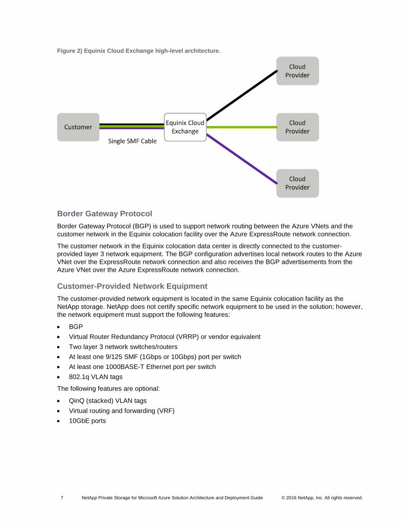
Figure 2) Equinix Cloud Exchange high-level architecture. ............................................................................................7
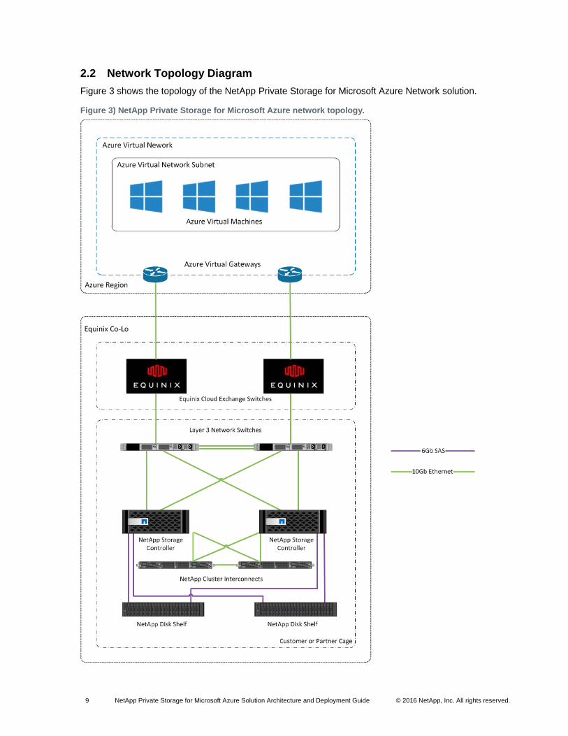
Figure 3) NetApp Private Storage for Microsoft Azure network topology. ......................................................................9
3 NetApp Private Storage for Microsoft Azure Solution Architecture and Deployment Guide © 2016 NetApp, Inc. All rights reserved.
1 NetApp Private Storage for Microsoft Azure Solution
This document describes the storage architecture of the NetApp Private Storage for Microsoft Azure
solution and provides procedures for deploying and testing the solution.
1.1 Assumptions
This document assumes that the reader has working knowledge of the following:
Microsoft Azure
Windows PowerShell
NetApp storage administration
Network administration
Windows and/or Linux administration
1.2 Use Case Overview
The NetApp Private Storage for Microsoft Azure solution is a cloud-connected storage architecture that
allows enterprises to build an agile cloud infrastructure that combines the scalability and flexibility of the
Microsoft Azure cloud with the control and performance of NetApp storage.
NetApp storage is deployed at an Equinix colocation facility and is connected to Microsoft Azure
computing resources through the Equinix Cloud Exchange and the Microsoft Azure ExpressRoute
service.
Typical use cases for the NetApp Private Storage for Microsoft Azure solution include the following:
Oracle, SQL Server, and SAP primary workloads
Disaster recovery
Development and test
Big data analytics
Data with compliance requirements
Data center migration and consolidation
For more information about NetApp Private Storage (NPS) use cases, see NVA-0009: NetApp Private
Storage for Cloud NetApp Validated Architecture.
1.3 Technical Overview
The NetApp Private Storage for Microsoft Azure solution combines computing resources from Microsoft
Azure with NetApp storage deployed at Equinix colocation facilities. Connectivity from the NetApp storage
to the Azure cloud is made possible by the Equinix Cloud Exchange and the Microsoft Azure
ExpressRoute service.
The Microsoft Azure ExpressRoute service offers dedicated high-bandwidth, low-latency, secure network
connectivity to the Azure cloud. ExpressRoute connections through the Equinix Cloud Exchange can be
at 200Mbps, 500Mbps, or 1Gbps.
In the Equinix colocation data center, the customer provides network equipment (switch or router) and
NetApp storage systems. Virtual machines (VMs) in the Azure cloud connect to the NetApp storage
through IP-based storage protocols (iSCSI, CIFS, or NFS). Additional MPLS or point-to-point VPN
network resources can be used to provide connectivity between Azure regions as well as connectivity to
the on-premises data centers.
4 NetApp Private Storage for Microsoft Azure Solution Architecture and Deployment Guide © 2016 NetApp, Inc. All rights reserved.
2 Solution Architecture
This section describes the components of the solution architecture, the network topology, and the security
features.
2.1 Solution Architecture Components
The solution architecture includes the following components:
Azure virtual machines (VMs) service
Azure virtual network (VNet) service
Azure ExpressRoute service
Equinix colocation data center
Equinix Cloud Exchange
Border Gateway Protocol (BGP)
Customer-provided layer 3 network equipment
NetApp storage (FAS and FlexArray® storage virtualization software)
Azure VMs Service
The Azure VMs service provides scalable, flexible, on-demand computing resources for the Azure cloud.
The environment allows VMs to be deployed from preconfigured VM images.
Azure VM Locations
The Azure VM service is available on a per-Azure-region basis. Each Azure region is tied to a specific
geographic region.
The Azure Management Portal can be used to deploy EC2 VM resources for the NetApp Private Storage
for Azure solution. Advanced Azure users can programmatically deploy Azure VMs through APIs and
scripts that use Azure command-line tools or Azure PowerShell modules.
For more information about locations where Azure VMs are available, see Azure Services by region in the
Microsoft Azure documentation.
Azure VM Instance Types
Azure VMs are available in different sizes. The size of the VM is a combination of CPU, memory, disk
size, and IOPS.
For more information about the Azure VM sizes available, see Windows Virtual Machine Sizes and Linux
Virtual Machine Sizes in the Microsoft Azure documentation.
Note: Not all instance types are available for all Azure regions.
Available Operating Systems
Azure VMs can run Windows or Linux OSs. For a list of supported Microsoft OSs and applications that
can run on an Azure VM, refer to Microsoft Server Software Support for Windows Azure Virtual Machines.
For a list of supported distributions and drivers for Linux OSs that can run on an Azure VM, refer to Linux
on Azure-Endorsed Distributions.
For each OS and application type, validate version compatibility with the NetApp client software and
ONTAP® version through the NetApp Interoperability Matrix Tool. (This site requires a NetApp Support
account login.)
5 NetApp Private Storage for Microsoft Azure Solution Architecture and Deployment Guide © 2016 NetApp, Inc. All rights reserved.
Azure VNet Service
The Azure VNet service provides isolated RFC 1918 IPv4 address ranges (10.0.0.0/8, 172.16.0.0/12,
192.186.0.0/16) in Azure into which Azure VMs can be deployed.
An Azure VNet can be customized, including its Classless Interdomain Routing (CIDR) IP address
ranges, subnets, routing, gateways, Domain Name System (DNS) settings, and network security.
The Azure VNet can be connected to the customer network located in Equinix in or to on-premises
networks through point-to-point VPN.
For more information, see the Azure Virtual Network documentation.
Azure ExpressRoute
Azure ExpressRoute is used to establish private dedicated network connections between the customer-
provided network equipment in the Equinix data center and the Azure VNet. ExpressRoute supports the
use of industry standard 802.1q VLANs.
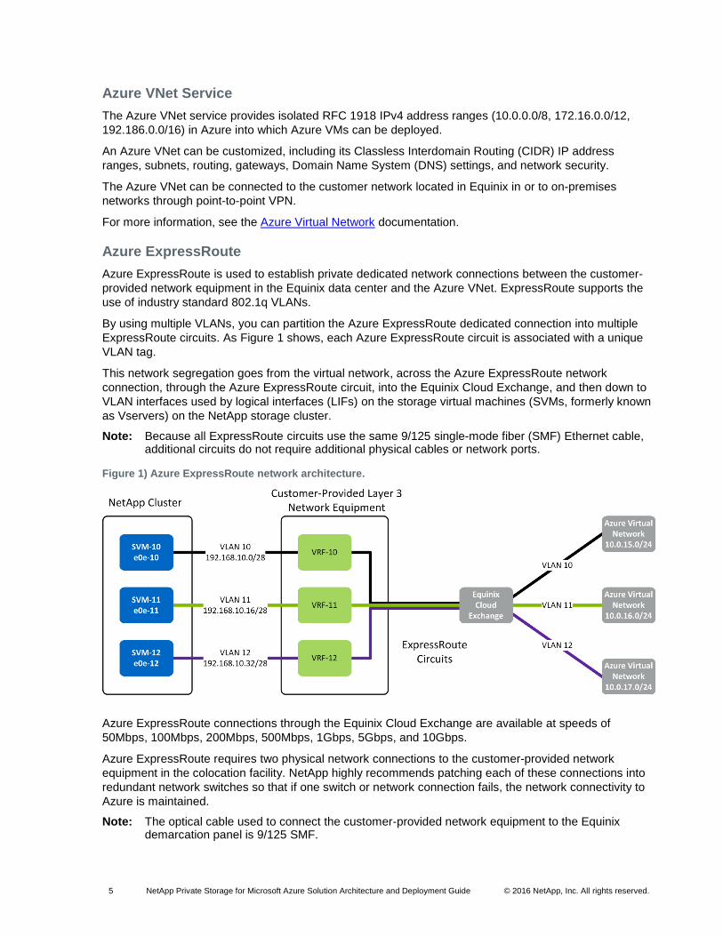
By using multiple VLANs, you can partition the Azure ExpressRoute dedicated connection into multiple
ExpressRoute circuits. As Figure 1 shows, each Azure ExpressRoute circuit is associated with a unique
VLAN tag.
This network segregation goes from the virtual network, across the Azure ExpressRoute network
connection, through the Azure ExpressRoute circuit, into the Equinix Cloud Exchange, and then down to
VLAN interfaces used by logical interfaces (LIFs) on the storage virtual machines (SVMs, formerly known
as Vservers) on the NetApp storage cluster.
Note: Because all ExpressRoute circuits use the same 9/125 single-mode fiber (SMF) Ethernet cable, additional circuits do not require additional physical cables or network ports.
Figure 1) Azure ExpressRoute network architecture.
Azure ExpressRoute connections through the Equinix Cloud Exchange are available at speeds of
50Mbps, 100Mbps, 200Mbps, 500Mbps, 1Gbps, 5Gbps, and 10Gbps.
Azure ExpressRoute requires two physical network connections to the customer-provided network
equipment in the colocation facility. NetApp highly recommends patching each of these connections into
redundant network switches so that if one switch or network connection fails, the network connectivity to
Azure is maintained.
Note: The optical cable used to connect the customer-provided network equipment to the Equinix demarcation panel is 9/125 SMF.
6 NetApp Private Storage for Microsoft Azure Solution Architecture and Deployment Guide © 2016 NetApp, Inc. All rights reserved.
For more information about Azure ExpressRoute, see the ExpressRoute documentation.
Equinix Colocation Data Center
Azure ExpressRoute Point of Presence
Equinix offers private connectivity to Azure that does not go over the Internet using the Equinix Cloud
Exchange. The Equinix Cloud Exchange peering points with Azure are located inside Equinix data
centers.
A list of Azure peering locations and associated Azure regions can be found in the Azure ExpressRoute
documentation.
For a list of observed latencies from Equinix to Azure, refer to NetApp Cloudlab Latencies documentation.
Note: Because customers might experience varying latencies, NetApp recommends validating the latency of the connectivity to Azure before deploying workloads into the NetApp Private Storage for Microsoft Azure solution.
Physical Security
Equinix colocation data centers offer a secure, highly available environment in which the customer-owned
NetApp storage and network equipment for the NetApp Private Storage for Microsoft Azure solution
reside. Equinix provides a high degree of physical security.
Customers have the option of deploying their storage into dedicated secure cages or into secure cabinets
in shared cages.
For more information about Equinix physical security, see the Equinix Physical Security web site.
Operational Security
Equinix facilities have a minimum N+1 power and cooling system redundancy. Many Equinix facilities
have N+2 power and cooling system redundancy.
For more information about Equinix operational reliability, refer to the Equinix Operational Reliability web
site.
Equinix Cloud Exchange
The Equinix Cloud Exchange is an Azure ExpressRoute Exchange provider. As Figure 2 shows, the
Equinix Cloud Exchange allows customers to rapidly connect to multiple network and cloud service
providers over an SMF optical cable. The dynamic connectivity of the Cloud Exchange provides the ability
to quickly connect and disconnect cloud services as customers’ technical and business requirements
change.
The Cloud Exchange portal is used by customers to request connectivity to Microsoft Azure through
Azure ExpressRoute.
To purchase ports on the Equinix Cloud Exchange, contact your Equinix account team.
7 NetApp Private Storage for Microsoft Azure Solution Architecture and Deployment Guide © 2016 NetApp, Inc. All rights reserved.
Figure 2) Equinix Cloud Exchange high-level architecture.
Border Gateway Protocol
Border Gateway Protocol (BGP) is used to support network routing between the Azure VNets and the
customer network in the Equinix colocation facility over the Azure ExpressRoute network connection.
The customer network in the Equinix colocation data center is directly connected to the customer-
provided layer 3 network equipment. The BGP configuration advertises local network routes to the Azure
VNet over the ExpressRoute network connection and also receives the BGP advertisements from the
Azure VNet over the Azure ExpressRoute network connection.
Customer-Provided Network Equipment
The customer-provided network equipment is located in the same Equinix colocation facility as the
NetApp storage. NetApp does not certify specific network equipment to be used in the solution; however,
the network equipment must support the following features:
BGP
Virtual Router Redundancy Protocol (VRRP) or vendor equivalent
Two layer 3 network switches/routers
At least one 9/125 SMF (1Gbps or 10Gbps) port per switch
At least one 1000BASE-T Ethernet port per switch
802.1q VLAN tags
The following features are optional:
QinQ (stacked) VLAN tags
Virtual routing and forwarding (VRF)
10GbE ports
8 NetApp Private Storage for Microsoft Azure Solution Architecture and Deployment Guide © 2016 NetApp, Inc. All rights reserved.
Required Feature Description
As noted previously, BGP is used to route network traffic between the local network in the Equinix data
center and the Azure VNet.
Azure ExpressRoute requires two physical connections (9/125 SMF) from the customer network
equipment to the Cloud Exchange. Redundant physical connections protect against potential loss of
ExpressRoute service caused by a failure in the physical link.
1000BASE-T network ports on the switch provide network connectivity from the NetApp storage cluster.
Although these ports can be used for data, NetApp recommends using 1GbE ports for node management
and out-of-band management.
802.1q VLAN tags are used by the Equinix Cloud Exchange and Azure ExpressRoute to segregate
network traffic on the same physical network connection.
Optional Feature Description
QinQ VLAN tags can be used by the Equinix Cloud Exchange to support the routing of the network traffic
from the network to Azure. The outer service tag (S-tag) is used to route traffic to Azure from the Cloud
Exchange. The inner customer tag (C-tag) is passed on to Azure for routing to the Azure VNet through
ExpressRoute.
Redundant network switches protect from a loss of ExpressRoute service caused by switch failure.
Note: For information about configuring redundant network switches, consult your network equipment vendor’s documentation.
Connecting 10GbE ports on the storage to the switch provides the highest amount of bandwidth capability
between the switch and the storage to support data access.
NetApp FAS Storage and FlexArray
Both NetApp clustered Data ONTAP and Data ONTAP operating in 7-Mode can function with the NetApp
Private Storage for Microsoft Azure solution; however, NetApp highly recommends using clustered Data
ONTAP with the solution.
9 NetApp Private Storage for Microsoft Azure Solution Architecture and Deployment Guide © 2016 NetApp, Inc. All rights reserved.
2.2 Network Topology Diagram
Figure 3 shows the topology of the NetApp Private Storage for Microsoft Azure Network solution.
Figure 3) NetApp Private Storage for Microsoft Azure network topology.
10 NetApp Private Storage for Microsoft Azure Solution Architecture and Deployment Guide © 2016 NetApp, Inc. All rights reserved.
2.3 NetApp Private Storage for Microsoft Azure Data Security Elements
According to many customer surveys, governance and control of data are primary concerns of enterprises
as they move data to the cloud. Regulatory compliance prohibiting the storage of data in the cloud is
another major area of concern. NetApp Private Storage for Microsoft Azure allows customers to store
their data on NetApp storage that they own or control so that they can maintain the compliance and
control of their data.
The solution contains the following security-related elements:
Microsoft Azure VNets
Microsoft Azure ExpressRoute
Equinix data center physical security
NetApp Data ONTAP FAS disk encryption
Third-party network security software
Microsoft Azure VNet
The Azure VNet provides isolation for the resources (VMs, services, and so forth) that are provisioned in
it. Azure resources provisioned in a virtual network can communicate with each other within the network.
Resources external to the virtual network do not have access to the resources in the virtual network.
Azure VNets can be accessed securely through an ExpressRoute site-to-site VPN connection,
ExpressRoute telco connection, or ExpressRoute exchange provider.
Microsoft Azure ExpressRoute
Azure ExpressRoute using an ExpressRoute exchange provider is a private, secure network connection
that does not traverse the Internet. The connectivity to Microsoft Azure from the NetApp storage in the
Equinix data center is through physical cross-connects that are not shared with other customers.
The Equinix Cloud Exchange provides an additional layer of segregation by leveraging VLAN tags for
Cloud Exchange virtual circuits to further isolate network traffic between Azure customers and Equinix.
Equinix Data Center Physical Security
Equinix provides state-of-the-art physical security at all of its data centers where Azure ExpressRoute is
available. The data centers have security guards and security systems to provide video surveillance. The
security systems have biometric hand scanners combined with mantrap interlocks to restrict access to
authorized personnel only.
For more information about Equinix physical security, refer to the Equinix Physical Security webpage.
NetApp Storage Encryption
NetApp Storage Encryption (NSE) software is the NetApp implementation of full-disk encryption (FDE)
that uses self-encrypting drives from leading vendors, allowing data on NetApp storage to be fully
encrypted while maintaining storage efficiency and performance.
For more information, refer to NetApp Storage Encryption.
Third-Party Network Security Hardware and Software
Third-party security hardware and software devices can be used with the NetApp Private Storage for
Microsoft Azure solution as long as the security solution can work in a TCP/IP environment because the
NetApp Private Storage for Microsoft Azure solution does not support Fibre Channel (FC) or Fibre
Channel over Ethernet (FCoE). NetApp does not certify third-party security solutions that can be used
with the NetApp Private Storage for Microsoft Azure solution. To implement a security solution with the
11 NetApp Private Storage for Microsoft Azure Solution Architecture and Deployment Guide © 2016 NetApp, Inc. All rights reserved.
NetApp Private Storage for Microsoft Azure solution, contact your NetApp account team for further
guidance.
3 NetApp Private Storage for Microsoft Azure Deployment Overview
This section describes the standard deployment methodology for NetApp Private Storage for Microsoft
Azure. However, because no two customer environments are the same, NetApp has delivery partners
who specialize in deploying NPS solutions. These partners are experienced and can help make your
NetApp Private Storage for Microsoft Azure deployment a success. For more information about NPS
delivery partners, contact your NetApp account representative.
The workflow for deploying the NetApp Private Storage for Microsoft Azure solution includes the following
tasks:
1. Planning:
a. Preinstallation and site preparation
2. Deployment:
a. Installing equipment in the Equinix data center
b. Setting up the Azure ExpressRoute
c. Setting up the Azure VNet
d. Setting up local network switches
e. Configuring NetApp storage
3. Validation:
a. Testing connections and protocol access
b. Testing iSCSI protocol connectivity
c. Performance test guidelines
3.1 Planning
Preinstallation and Site Preparation
The preinstallation and site preparation take place during the planning phase of the NetApp Private
Storage for Microsoft Azure workflow. This includes:
1. Establishing the colocation power and space requirements
2. Ordering space and power
3. Ordering the network, storage, and rack hardware
4. Creating an IP address plan
5. Obtaining Azure and Equinix portal accounts
6. Ordering the Equinix Cloud Exchange ports from Equinix
7. Creating an inbound shipment request through Equinix
8. Installing the Azure PowerShell modules
Establishing Colocation Power and Space Requirements
Use the NetApp Hardware Universe or contact your NetApp account team to determine the power and
space requirements for the NetApp storage you want to deploy with the NetApp Private Storage for
Microsoft Azure solution.
12 NetApp Private Storage for Microsoft Azure Solution Architecture and Deployment Guide © 2016 NetApp, Inc. All rights reserved.
See the technical specifications or contact your network switch vendor about the power and space
requirements of the network equipment that you want to deploy with NetApp Private Storage for Microsoft
Azure.
Ordering Space and Power
There are two types of colocation space at Equinix: shared and dedicated. A shared space is a secure
cage containing secure cabinets used by multiple customers. Customers are required to use Equinix
racks in a shared-space configuration.
A dedicated space is a secure cage that is assigned to a single customer. The smallest dedicated cage
consists of five cabinets. Customers can either use Equinix standard racks or use their own.
It is recommended that customers use redundant power connections connected to separate power
distribution units (PDUs) so that the NPS solution can survive the loss of a single power connection.
The typical power connection configuration used with NPS is 208V/30A single-phase AC power. The
voltage specifications may vary from region to region.
Contact your Equinix account team for more information about the available space and power options in
the Equinix data center where you want to deploy NPS.
Ordering Network, Storage, and Rack Hardware
If you require more than six ports of power on a PDU, you need to purchase a third-party PDU or order
additional power connections from Equinix. Equinix sells PDUs that fit well with its cabinets. The Equinix
cabinets are standard 42U, 4-post racks.
Contact your NetApp account team to make sure that you are ordering the appropriate rail kits for your
cabinets.
If you are using a secure cabinet in a shared cage, you need to order a top-of-rack demarcation panel to
connect the network equipment to the Equinix Cloud Exchange. The type of demarcation panel should be
24-port SC optical.
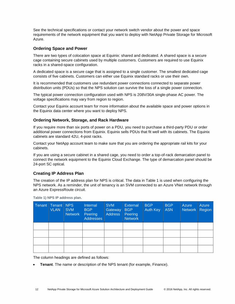
Creating IP Address Plan
The creation of the IP address plan for NPS is critical. The data in Table 1 is used when configuring the
NPS network. As a reminder, the unit of tenancy is an SVM connected to an Azure VNet network through
an Azure ExpressRoute circuit.
Table 1) NPS IP address plan.
Tenant Tenant VLAN
NPS SVM Network
Internal BGP Peering Addresses
SVM Gateway Address
External BGP Peering Network
BGP Auth Key
BGP ASN
Azure Network
Azure Region
The column headings are defined as follows:
Tenant. The name or description of the NPS tenant (for example, Finance).
13 NetApp Private Storage for Microsoft Azure Solution Architecture and Deployment Guide © 2016 NetApp, Inc. All rights reserved.
Tenant VLAN. The VLAN number that the NPS tenant uses to connect the NetApp storage assigned to them to the Azure VNet over an Azure ExpressRoute circuit (for example, 65).
NPS SVM network. The network CIDR that is used by the NetApp SVM logical network interfaces.
The network is typically a private network CIDR (for example, 192.168.25.32/28), but can be a
public network CIDR if you are using a public ExpressRoute circuit.
Internal BGP peering addresses. These addresses are part of the SVM network (for example,
192.168.25.34 and 192.168.25.35). They are used for the peering between the switches so that
routing is preserved in the case there is a loss of a port, cable, or switch. Each IP address is assigned to each VLAN interface used by the tenant.
SVM gateway address. The IP address that is used by the SVM as the network gateway. This IP address is a (VRRP or vendor equivalent) virtual IP address and is configured on each switch. This
address is in the SVM network (for example, 192.168.25.33) and is assigned to a VLAN interface
on each switch.
External BGP peering network. Azure requires two physical connections and two peering networks.
Each peering network is a /30 network (for example, 192.168.202.180/30 and
192.168.202.184/30). Each peering network is assigned to a switch.
Note: The lower IP address number of the peering network (for example, 192.168.202.181/30) is assigned to the layer 3 interface on the network equipment in Equinix, and the higher number (for example, 192.168.202.182/30) is assigned to the Azure VNet Gateway.
BGP authentication key. A text string that represents a shared key between the network equipment in Equinix and Azure. This key securely establishes the external BGP session (for example,
f291423b811fcb483aba30e7).
BGP autonomous system number (BGP ASN). A unique number assigned to the network equipment in Equinix. The ASN can be a private or public number. Private ASN numbers range from 64512 to 65535 (our example uses 64514).
Note: ASN 65515–65520 are reserved for Azure usage and cannot be used.
Azure network. The network CIDR of the Azure VNet (for example, 10.174.0.0/20).
Azure region. The Azure region in which the VNet is created and connected through Azure ExpressRoute (for example, West U.S.).
Obtaining Azure and Equinix Customer Portal Accounts
If you do not have an Azure account, see to the How to Buy Azure documentation or contact the Azure
Enterprise Agreement administrator for your organization.
Contact your Equinix account team to get your account set up in the Equinix Customer Portal and the
Equinix Cloud Exchange Portal.
Ordering Equinix Cloud Exchange Ports from Equinix
Order two Cloud Exchange ports for Azure ExpressRoute by contacting your Equinix account team.
There are two types of Cloud Exchange network ports:
A standard Cloud Exchange network port, which is a physical network port on the Cloud Exchange switch that can be shared with multiple customers.
A buyout Cloud Exchange port, which is a physical port on the Cloud Exchange switch that is dedicated to a single customer.
There are two sizes of Cloud Exchange network ports: 1Gbps single-mode Fibre and 10Gbps single-
mode Fibre.
Note: 10Gbps Azure ExpressRoute circuits require 10Gbps buyout ports.
14 NetApp Private Storage for Microsoft Azure Solution Architecture and Deployment Guide © 2016 NetApp, Inc. All rights reserved.
Creating Inbound Shipment Request Through Equinix
Equinix physical security procedures require that there be an inbound shipping request for any shipments
sent to an Equinix data center. The shipping addresses for the data center (also known as IBX) can be
found in the Equinix Customer Portal.
In the inbound shipment request, make sure to provide the shipper, shipment tracking number, number
and weight of items in the shipment, and date on which the shipment is expected to arrive at the IBX.
When shipping equipment to the Equinix data center, the format of the address should be as follows:
Name of cage/suite
c/o Equinix
Address of the data center
For more information about Equinix shipping and receiving procedures for your IBX, see the Equinix
Customer Portal or contact your Equinix Client Services manager.
Installing Azure PowerShell Modules
There are two types of Azure management deployment frameworks: Service Manager and Resource
Manager. Azure Service Manager is also known as the classic resource deployment model. Azure
Resource Manager is the new resource deployment model that Microsoft recommends for all new Azure
resource deployments.
The main advantage of using Azure Resource Manager is that you can deploy, manage, monitor, and
deprovision Azure resources as a group. Role-based access control (RBAC) is another significant
advantage of using Azure Resource Manager.
For more information about the differences between Azure Service Manager and Azure Resource
Manager, see the Azure Resource Manager documentation.
Note: This deployment guide uses Azure Resource Management PowerShell modules.
To install the Azure PowerShell modules, run the following command from an Internet-connected
Windows 8 or Windows 2012 (or higher) computer:
Install-Module AzureRm
The installation updates the $env:PSModulePath environment variable with the directories where the
modules are installed.
To verify that the Azure PowerShell modules are installed, run the following command:
Get-Module -ListAvailable
For more information about how to install Azure PowerShell modules, see the Azure PowerShell
documentation.
3.2 Deployment
Installing Equipment in Equinix Data Center
You can begin to install the equipment in the data center after the preinstallation and site preparation
phase is complete.
To set up the data center, complete the following steps:
1. Set up security access to the Equinix data center and cage.
2. Make sure that all required materials (hardware, software, accessories, and so on) are available on site.
15 NetApp Private Storage for Microsoft Azure Solution Architecture and Deployment Guide © 2016 NetApp, Inc. All rights reserved.
3. Install the NetApp storage in the rack.
4. Install the customer-provided network equipment in the rack.
5. Patch network equipment to the demarcation panel.
Setting Security Access to Equinix Data Center and Cage
Use the Equinix Customer Portal to create a security access request for the Equinix IBX where the NPS
solution is being deployed. The security access registration process includes a biometric scan, PIN
assignment, and security card assignment (depending on the IBX). You need to bring a government-
issued identification to the IBX.
Note: It is vital that the name on the security access request is identical to the government-issued identification, or Equinix security will not process the request.
After the security access process is complete, you are able to visit the Equinix IBX without the need for an
Equinix work visit request.
Making Sure That Required Materials Are Available on Site
The shipment can be inventoried in person, or the Equinix SmartHands technicians can inventory the
shipment. If you want to have the Equinix SmartHands technicians inventory the shipment, use the
Equinix Customer Portal to create a SmartHands request.
Installing NetApp Storage in the Rack
If you are using an Equinix cabinet in a shared cage, the NetApp storage can be installed in person, or
you can have a NetApp partner install the storage.
If you are using a dedicated Equinix cage, the racks in the cage must be installed. Use the Equinix
Customer Portal to create an Equinix SmartHands request to have the racks installed.
If you are having a NetApp partner install the storage, use the Equinix Customer Portal to create a work
visit request for the partner engineers. The engineers need to bring a government-issued identification,
and the names on the work visit request must match the government-issued identification.
Due to Equinix safety rules, the power distribution units (PDUs) in the rack need to be connected to
Equinix power by an Equinix SmartHands technician. Use the Equinix Customer Portal to create a
SmartHands request to connect the PDUs.
Installing Customer-Provided Network Equipment in the Rack
The network equipment can be installed at the same time as the NetApp storage.
If the network equipment is to be installed at a different time, use the Equinix Customer Portal to create a
work visit request for the partner engineers. The engineers need to bring a government-issued
identification, and the names on the work visit request must match the government-issued identification.
Patching Network Equipment to Demarcation Panel
After the network equipment and the Cloud Exchange ports have been patched to the demarcation panel,
patch the switches to the ports on the demarcation panel.
After the switches are patched to the demarcation panel, schedule a network turnup using the Equinix
Customer Portal or through your Equinix Client Services Manager.
16 NetApp Private Storage for Microsoft Azure Solution Architecture and Deployment Guide © 2016 NetApp, Inc. All rights reserved.
Setting Up Azure ExpressRoute
To set up Azure ExpressRoute, complete the following steps:
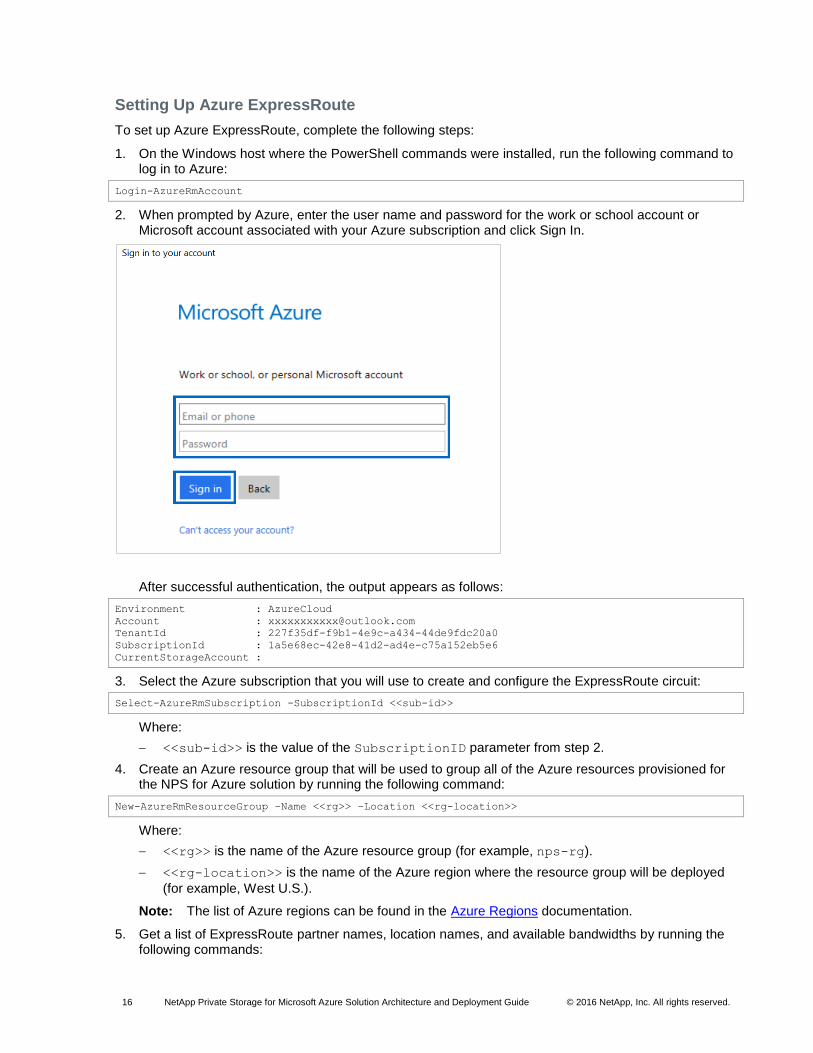
1. On the Windows host where the PowerShell commands were installed, run the following command to log in to Azure:
Login-AzureRmAccount
2. When prompted by Azure, enter the user name and password for the work or school account or Microsoft account associated with your Azure subscription and click Sign In.
After successful authentication, the output appears as follows:
Environment : AzureCloud
Account : [email protected]
TenantId : 227f35df-f9b1-4e9c-a434-44de9fdc20a0
SubscriptionId : 1a5e68ec-42e8-41d2-ad4e-c75a152eb5e6
CurrentStorageAccount :
3. Select the Azure subscription that you will use to create and configure the ExpressRoute circuit:
Select-AzureRmSubscription -SubscriptionId <<sub-id>>
Where:
<<sub-id>> is the value of the SubscriptionID parameter from step 2.
4. Create an Azure resource group that will be used to group all of the Azure resources provisioned for the NPS for Azure solution by running the following command:
New-AzureRmResourceGroup –Name <<rg>> –Location <<rg-location>>
Where:
<<rg>> is the name of the Azure resource group (for example, nps-rg).
<<rg-location>> is the name of the Azure region where the resource group will be deployed
(for example, West U.S.).
Note: The list of Azure regions can be found in the Azure Regions documentation.
5. Get a list of ExpressRoute partner names, location names, and available bandwidths by running the following commands:
17 NetApp Private Storage for Microsoft Azure Solution Architecture and Deployment Guide © 2016 NetApp, Inc. All rights reserved.
$FormatEnumerationLimit = 20
Get-AzureRmExpressRouteServiceProvider | fl Name,PeeringLocations,BandwidthsOffered
The output of the command appears as follows for Equinix:
Name : Equinix
PeeringLocations : {Amsterdam, Atlanta, Chicago, Dallas, Hong Kong, London, Los Angeles,
Melbourne, New York, Osaka, Sao Paulo, Seattle, Silicon Valley, Singapore,
Sydney, Tokyo, Toronto, Washington DC}
BandwidthsOffered : {50Mbps, 100Mbps, 200Mbps, 500Mbps, 1Gbps, 2Gbps, 5Gbps, 10Gbps}
6. Create the Azure ExpressRoute circuit by running the following command:
New-AzureRmExpressRouteCircuit –Name <<ckt-name>> –ResourceGroupName <<rg>> –Location <<rg-
location>> –SkuTier <<sku-tier>> –SkuFamily <<sku-family>> –ServiceProviderName <<sp-name>> –
PeeringLocation <<peer-location>> –BandwidthInMbps <<bandwidth>>
Where:
<<ckt-name>> is the name of the ExpressRoute circuit (for example, nps-sv5-65).
<<rg>> is the name of the Azure resource group created in step 4 (for example, nps-rg).
<<rg-location>> is the name of the Azure region used in step 4 (for example, West U.S.).
<<sku-tier>> is the SKU tier for the ExpressRoute circuit. The value of this parameter is
Standard or Premium (in this example, Standard).
<<sku-family>> is the SKU family for the ExpressRoute circuit. The value of this parameter is
MeteredData or UnlimitedData (in this example, MeteredData).
<<sp-name>> is the name of the Azure ExpressRoute partner (for example, Equinix).
<<peer-location>> is the name of the metro location where the Equinix Cloud Exchange is
located (in this example, Silicon Valley).
<<bandwidth>> is the bandwidth of the ExpressRoute circuit (for example, 1000).
Note: 10Gbps ExpressRoute circuits require buyout ports on the Equinix Cloud Exchange.
The output of the command appears as follows:
Name : nps-sv5-65
ResourceGroupName : nps-rg
Location : westus
Id : /subscriptions/1a5e68ec-42e8-41d2-ad4e-
b75a152eb5e6/resourceGroups/nps-rg/providers/
Microsoft.Network/expressRouteCircuits/nps-sv5-65
Etag : W/"c15b4e8a-b103-41b2-aaf0-ae110ae37cf9"
ProvisioningState : Succeeded
Sku : {
"Name": "Standard_MeteredData",
"Tier": "Standard",
"Family": "MeteredData"
}
CircuitProvisioningState : Enabled
ServiceProviderProvisioningState : NotProvisioned
ServiceProviderNotes :
ServiceProviderProperties : {
"ServiceProviderName": "Equinix",
"PeeringLocation": "Silicon Valley",
"BandwidthInMbps": 1000
}
ServiceKey : 1969f4df-0298-40ca-94e0-b7e12bfdfe94
Peerings : []
Authorizations : []
AllowClassicOperations : False
18 NetApp Private Storage for Microsoft Azure Solution Architecture and Deployment Guide © 2016 NetApp, Inc. All rights reserved.
Note: The value of the ServiceProviderProvisioningState is NotProvisioned until the ExpressRoute circuit is linked to an Equinix Cloud Exchange virtual circuit using the value of the ServiceKey parameter.
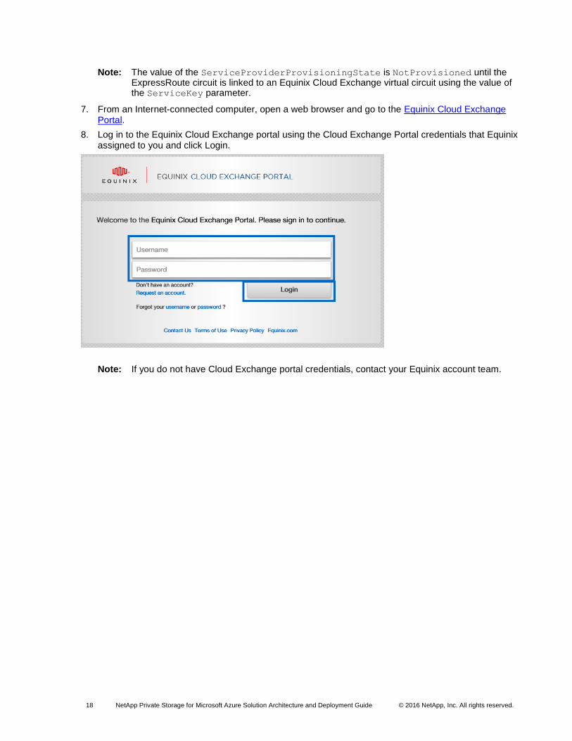
7. From an Internet-connected computer, open a web browser and go to the Equinix Cloud Exchange Portal.
8. Log in to the Equinix Cloud Exchange portal using the Cloud Exchange Portal credentials that Equinix assigned to you and click Login.
Note: If you do not have Cloud Exchange portal credentials, contact your Equinix account team.
19 NetApp Private Storage for Microsoft Azure Solution Architecture and Deployment Guide © 2016 NetApp, Inc. All rights reserved.
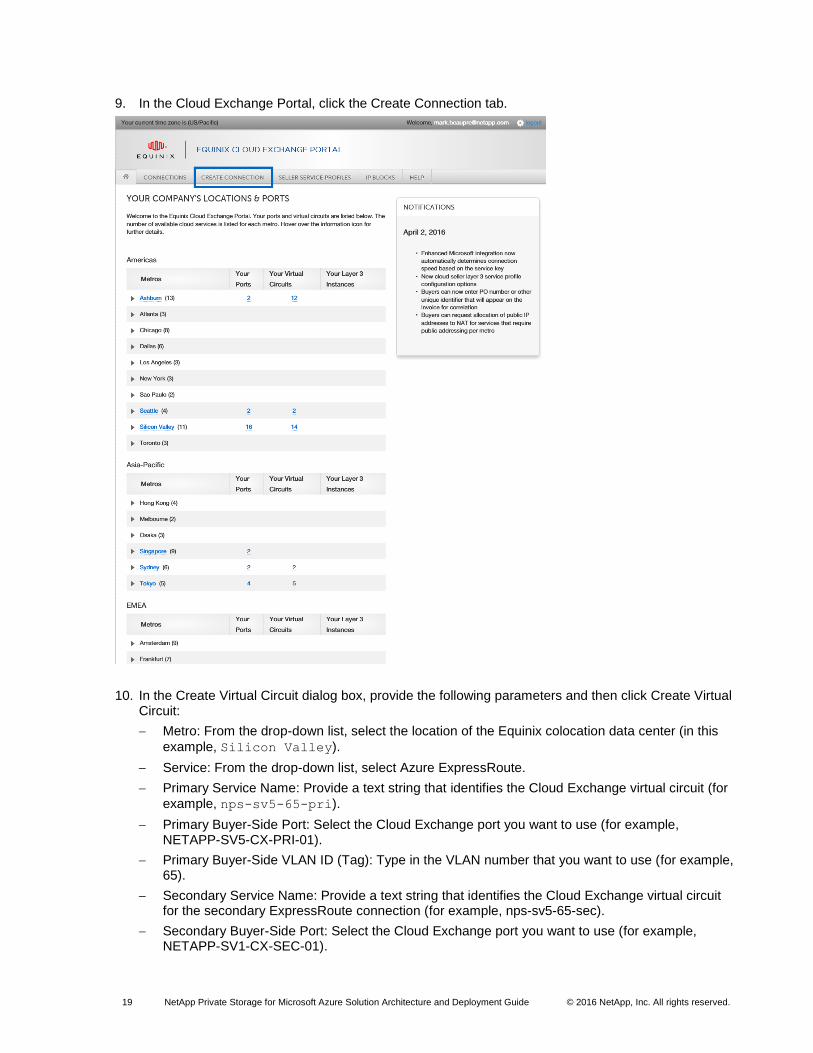
9. In the Cloud Exchange Portal, click the Create Connection tab.
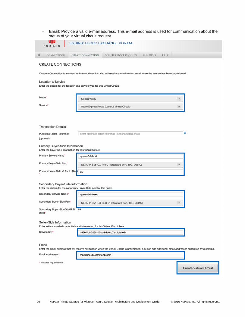
10. In the Create Virtual Circuit dialog box, provide the following parameters and then click Create Virtual Circuit:
Metro: From the drop-down list, select the location of the Equinix colocation data center (in this
example, Silicon Valley).
Service: From the drop-down list, select Azure ExpressRoute.
Primary Service Name: Provide a text string that identifies the Cloud Exchange virtual circuit (for
example, nps-sv5-65-pri).
Primary Buyer-Side Port: Select the Cloud Exchange port you want to use (for example, NETAPP-SV5-CX-PRI-01).
Primary Buyer-Side VLAN ID (Tag): Type in the VLAN number that you want to use (for example, 65).
Secondary Service Name: Provide a text string that identifies the Cloud Exchange virtual circuit for the secondary ExpressRoute connection (for example, nps-sv5-65-sec).
Secondary Buyer-Side Port: Select the Cloud Exchange port you want to use (for example, NETAPP-SV1-CX-SEC-01).
20 NetApp Private Storage for Microsoft Azure Solution Architecture and Deployment Guide © 2016 NetApp, Inc. All rights reserved.
Email: Provide a valid e-mail address. This e-mail address is used for communication about the status of your virtual circuit request.
21 NetApp Private Storage for Microsoft Azure Solution Architecture and Deployment Guide © 2016 NetApp, Inc. All rights reserved.
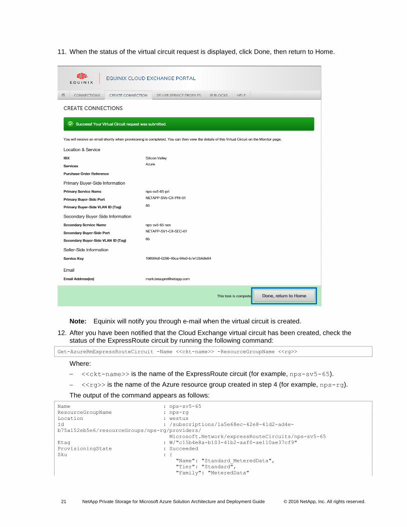
11. When the status of the virtual circuit request is displayed, click Done, then return to Home.
Note: Equinix will notify you through e-mail when the virtual circuit is created.
12. After you have been notified that the Cloud Exchange virtual circuit has been created, check the status of the ExpressRoute circuit by running the following command:
Get-AzureRmExpressRouteCircuit -Name <<ckt-name>> -ResourceGroupName <<rg>>
Where:
<<ckt-name>> is the name of the ExpressRoute circuit (for example, nps-sv5-65).
<<rg>> is the name of the Azure resource group created in step 4 (for example, nps-rg).
The output of the command appears as follows:
Name : nps-sv5-65
ResourceGroupName : nps-rg
Location : westus
Id : /subscriptions/1a5e68ec-42e8-41d2-ad4e-
b75a152eb5e6/resourceGroups/nps-rg/providers/
Microsoft.Network/expressRouteCircuits/nps-sv5-65
Etag : W/"c15b4e8a-b103-41b2-aaf0-ae110ae37cf9"
ProvisioningState : Succeeded
Sku : {
"Name": "Standard_MeteredData",
"Tier": "Standard",
"Family": "MeteredData"
22 NetApp Private Storage for Microsoft Azure Solution Architecture and Deployment Guide © 2016 NetApp, Inc. All rights reserved.
}
CircuitProvisioningState : Enabled
ServiceProviderProvisioningState : Provisioned
ServiceProviderNotes :
ServiceProviderProperties : {
"ServiceProviderName": "Equinix",
"PeeringLocation": "Silicon Valley",
"BandwidthInMbps": 1000
}
ServiceKey : 1969f4df-0298-40ca-94e0-b7e12bfdfe94
Peerings : []
Authorizations : []
AllowClassicOperations : False
Note: The value of the ServiceProviderProvisioningState parameter should change to Provisioned.
13. After the ExpressRoute circuit has been successfully provisioned, run the following commands to configure BGP peering on the ExpressRoute circuit:
$ckt = Get-AzureRmExpressRouteCircuit -Name <<ckt-name>> –ResourceGroup <<rg>>
Add-AzureRmExpressRouteCircuitPeeringConfig –Name <<ckt-peer-cfg>> –ExpressRouteCircuit $ckt –
PeeringType AzurePrivatePeering –PeerASN <<asn>> –PrimaryPeerAddressPrefix <<pri-peer-cidr>> –
SecondaryPeerAddressPrefix <<sec-peer-cidr>> –VlanId <<vlan>> -SharedKey <<bgp-key>>
Set-AzureRmExpressRouteCircuit –ExpressRouteCircuit $ckt
Where:
<<ckt-name>> is the name of the ExpressRoute circuit (for example, nps-sv5-65).
<<rg>> is the name of the Azure resource group created in step 4 (for example, nps-rg).
<<ckt-peer-cfg>> is the name of the Azure BGP peering configuration (for example,
AzurePrivatePeering).
<<asn>> is the autonomous system number of your network equipment in Equinix (for example,
64514).
<<pri-peer-cidr>> is the CIDR of the primary peering network (for example,
92.168.202.180/30).
<<sec-peer-cidr>> is the CIDR of the secondary peering network (for example,
192.168.202.184/30).
<<vlan-id>> is the VLAN number used for the ExpressRoute circuit (for example, 65).
<<bgp-key>> is the BGP shared key used to establish the BGP session for the ExpressRoute
circuit (for example, f291423b811fcb483aba30e7).
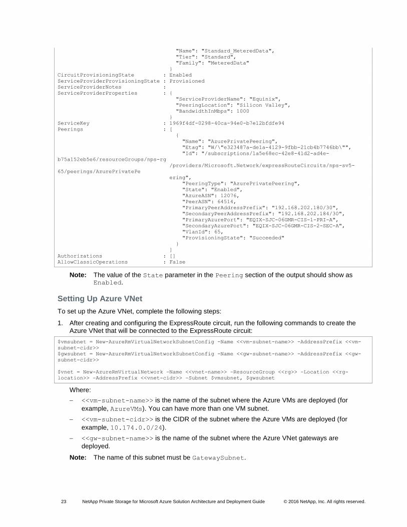
14. Validate the configuration of the ExpressRoute circuit by running the following command:
Get-AzureRmExpressRouteCircuit –Name <<ckt-name>> –ResourceGroup <<rg>>
Where:
<<ckt-name>> is the name of the ExpressRoute circuit (for example, nps-sv5-65).
<<rg>> is the name of the Azure resource group created in step 4 (for example, nps-rg).
The output of the command appears as follows:
Name : nps-sv5-65
ResourceGroupName : nps-rg
Location : westus
Id : /subscriptions/1a5e68ec-42e8-41d2-ad4e-
b75a152eb5e6/resourceGroups/nps-rg/providers/
Microsoft.Network/expressRouteCircuits/nps-sv5-65
Etag : W/"e323487a-de1a-4129-9fbb-21cb4b7746bb"
ProvisioningState : Succeeded
Sku : {
23 NetApp Private Storage for Microsoft Azure Solution Architecture and Deployment Guide © 2016 NetApp, Inc. All rights reserved.
"Name": "Standard_MeteredData",
"Tier": "Standard",
"Family": "MeteredData"
}
CircuitProvisioningState : Enabled
ServiceProviderProvisioningState : Provisioned
ServiceProviderNotes :
ServiceProviderProperties : {
"ServiceProviderName": "Equinix",
"PeeringLocation": "Silicon Valley",
"BandwidthInMbps": 1000
}
ServiceKey : 1969f4df-0298-40ca-94e0-b7e12bfdfe94
Peerings : [
{
"Name": "AzurePrivatePeering",
"Etag": "W/\"e323487a-de1a-4129-9fbb-21cb4b7746bb\"",
"Id": "/subscriptions/1a5e68ec-42e8-41d2-ad4e-
b75a152eb5e6/resourceGroups/nps-rg
/providers/Microsoft.Network/expressRouteCircuits/nps-sv5-
65/peerings/AzurePrivatePe
ering",
"PeeringType": "AzurePrivatePeering",
"State": "Enabled",
"AzureASN": 12076,
"PeerASN": 64514,
"PrimaryPeerAddressPrefix": "192.168.202.180/30",
"SecondaryPeerAddressPrefix": "192.168.202.184/30",
"PrimaryAzurePort": "EQIX-SJC-06GMR-CIS-1-PRI-A",
"SecondaryAzurePort": "EQIX-SJC-06GMR-CIS-2-SEC-A",
"VlanId": 65,
"ProvisioningState": "Succeeded"
}
]
Authorizations : []
AllowClassicOperations : False
Note: The value of the State parameter in the Peering section of the output should show as Enabled.
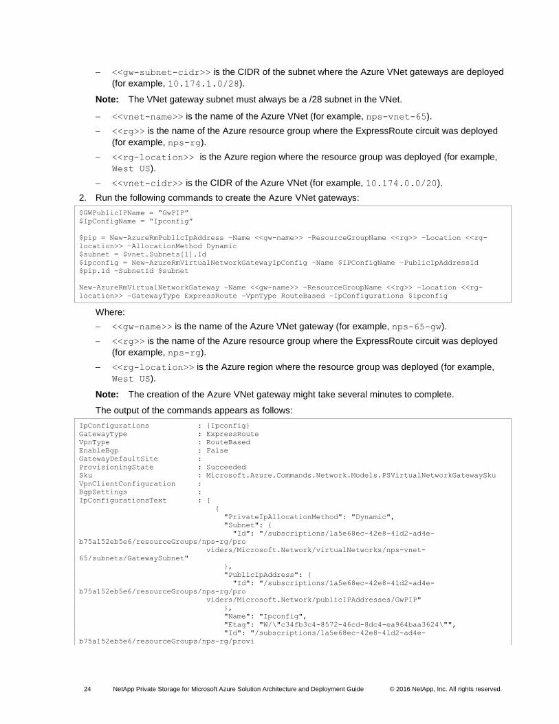
Setting Up Azure VNet
To set up the Azure VNet, complete the following steps:
1. After creating and configuring the ExpressRoute circuit, run the following commands to create the Azure VNet that will be connected to the ExpressRoute circuit:
$vmsubnet = New-AzureRmVirtualNetworkSubnetConfig -Name <<vm-subnet-name>> -AddressPrefix <<vm-
subnet-cidr>>
$gwsubnet = New-AzureRmVirtualNetworkSubnetConfig -Name <<gw-subnet-name>> -AddressPrefix <<gw-
subnet-cidr>>
$vnet = New-AzureRmVirtualNetwork –Name <<vnet-name>> –ResourceGroup <<rg>> –Location <<rg-
location>> –AddressPrefix <<vnet-cidr>> –Subnet $vmsubnet, $gwsubnet
Where:
<<vm-subnet-name>> is the name of the subnet where the Azure VMs are deployed (for
example, AzureVMs). You can have more than one VM subnet.
<<vm-subnet-cidr>> is the CIDR of the subnet where the Azure VMs are deployed (for
example, 10.174.0.0/24).
<<gw-subnet-name>> is the name of the subnet where the Azure VNet gateways are
deployed.
Note: The name of this subnet must be GatewaySubnet.
24 NetApp Private Storage for Microsoft Azure Solution Architecture and Deployment Guide © 2016 NetApp, Inc. All rights reserved.
<<gw-subnet-cidr>> is the CIDR of the subnet where the Azure VNet gateways are deployed
(for example, 10.174.1.0/28).
Note: The VNet gateway subnet must always be a /28 subnet in the VNet.
<<vnet-name>> is the name of the Azure VNet (for example, nps-vnet-65).
<<rg>> is the name of the Azure resource group where the ExpressRoute circuit was deployed
(for example, nps-rg).
<<rg-location>> is the Azure region where the resource group was deployed (for example,
West US).
<<vnet-cidr>> is the CIDR of the Azure VNet (for example, 10.174.0.0/20).
2. Run the following commands to create the Azure VNet gateways:
$GWPublicIPName = “GwPIP”
$IpConfigName = “Ipconfig”
$pip = New-AzureRmPublicIpAddress –Name <<gw-name>> –ResourceGroupName <<rg>> –Location <<rg-
location>> –AllocationMethod Dynamic
$subnet = $vnet.Subnets[1].Id
$ipconfig = New-AzureRmVirtualNetworkGatewayIpConfig –Name $IPConfigName –PublicIpAddressId
$pip.Id –SubnetId $subnet
New-AzureRmVirtualNetworkGateway –Name <<gw-name>> –ResourceGroupName <<rg>> –Location <<rg-
location>> –GatewayType ExpressRoute –VpnType RouteBased –IpConfigurations $ipconfig
Where:
<<gw-name>> is the name of the Azure VNet gateway (for example, nps-65-gw).
<<rg>> is the name of the Azure resource group where the ExpressRoute circuit was deployed
(for example, nps-rg).
<<rg-location>> is the Azure region where the resource group was deployed (for example,
West US).
Note: The creation of the Azure VNet gateway might take several minutes to complete.
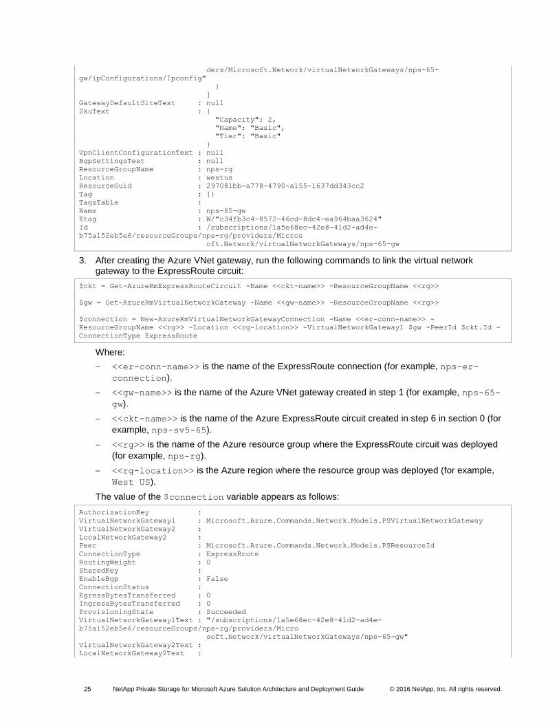
The output of the commands appears as follows:
IpConfigurations : {Ipconfig}
GatewayType : ExpressRoute
VpnType : RouteBased
EnableBgp : False
GatewayDefaultSite :
ProvisioningState : Succeeded
Sku : Microsoft.Azure.Commands.Network.Models.PSVirtualNetworkGatewaySku
VpnClientConfiguration :
BgpSettings :
IpConfigurationsText : [
{
"PrivateIpAllocationMethod": "Dynamic",
"Subnet": {
"Id": "/subscriptions/1a5e68ec-42e8-41d2-ad4e-
b75a152eb5e6/resourceGroups/nps-rg/pro
viders/Microsoft.Network/virtualNetworks/nps-vnet-
65/subnets/GatewaySubnet"
},
"PublicIpAddress": {
"Id": "/subscriptions/1a5e68ec-42e8-41d2-ad4e-
b75a152eb5e6/resourceGroups/nps-rg/pro
viders/Microsoft.Network/publicIPAddresses/GwPIP"
},
"Name": "Ipconfig",
"Etag": "W/\"c34fb3c4-8572-46cd-8dc4-ea964baa3624\"",
"Id": "/subscriptions/1a5e68ec-42e8-41d2-ad4e-
b75a152eb5e6/resourceGroups/nps-rg/provi
25 NetApp Private Storage for Microsoft Azure Solution Architecture and Deployment Guide © 2016 NetApp, Inc. All rights reserved.
ders/Microsoft.Network/virtualNetworkGateways/nps-65-
gw/ipConfigurations/Ipconfig"
}
]
GatewayDefaultSiteText : null
SkuText : {
"Capacity": 2,
"Name": "Basic",
"Tier": "Basic"
}
VpnClientConfigurationText : null
BgpSettingsText : null
ResourceGroupName : nps-rg
Location : westus
ResourceGuid : 297081bb-a778-4790-a155-1637dd343cc2
Tag : {}
TagsTable :
Name : nps-65-gw
Etag : W/"c34fb3c4-8572-46cd-8dc4-ea964baa3624"
Id : /subscriptions/1a5e68ec-42e8-41d2-ad4e-
b75a152eb5e6/resourceGroups/nps-rg/providers/Micros
oft.Network/virtualNetworkGateways/nps-65-gw
3. After creating the Azure VNet gateway, run the following commands to link the virtual network gateway to the ExpressRoute circuit:
$ckt = Get-AzureRmExpressRouteCircuit -Name <<ckt-name>> -ResourceGroupName <<rg>>
$gw = Get-AzureRmVirtualNetworkGateway -Name <<gw-name>> -ResourceGroupName <<rg>>
$connection = New-AzureRmVirtualNetworkGatewayConnection -Name <<er-conn-name>> -
ResourceGroupName <<rg>> -Location <<rg-location>> -VirtualNetworkGateway1 $gw -PeerId $ckt.Id -
ConnectionType ExpressRoute
Where:
<<er-conn-name>> is the name of the ExpressRoute connection (for example, nps-er-
connection).
<<gw-name>> is the name of the Azure VNet gateway created in step 1 (for example, nps-65-
gw).
<<ckt-name>> is the name of the Azure ExpressRoute circuit created in step 6 in section 0 (for
example, nps-sv5-65).
<<rg>> is the name of the Azure resource group where the ExpressRoute circuit was deployed
(for example, nps-rg).
<<rg-location>> is the Azure region where the resource group was deployed (for example,
West US).
The value of the $connection variable appears as follows:
AuthorizationKey :
VirtualNetworkGateway1 : Microsoft.Azure.Commands.Network.Models.PSVirtualNetworkGateway
VirtualNetworkGateway2 :
LocalNetworkGateway2 :
Peer : Microsoft.Azure.Commands.Network.Models.PSResourceId
ConnectionType : ExpressRoute
RoutingWeight : 0
SharedKey :
EnableBgp : False
ConnectionStatus :
EgressBytesTransferred : 0
IngressBytesTransferred : 0
ProvisioningState : Succeeded
VirtualNetworkGateway1Text : "/subscriptions/1a5e68ec-42e8-41d2-ad4e-
b75a152eb5e6/resourceGroups/nps-rg/providers/Micro
soft.Network/virtualNetworkGateways/nps-65-gw"
VirtualNetworkGateway2Text :
LocalNetworkGateway2Text :
26 NetApp Private Storage for Microsoft Azure Solution Architecture and Deployment Guide © 2016 NetApp, Inc. All rights reserved.
PeerText : "/subscriptions/1a5e68ec-42e8-41d2-ad4e-
b75a152eb5e6/resourceGroups/nps-rg/providers/Micro
soft.Network/expressRouteCircuits/nps-sv5-65"
ResourceGroupName : nps-rg
Location : westus
ResourceGuid : e7ca48d3-a21c-4138-b7af-11ea287c65fe
Tag : {}
TagsTable :
Name : nps-65-erconnection
Etag : W/"b552e54a-dd34-402e-973b-85eb63d24cf9"
Id : /subscriptions/1a5e68ec-42e8-41d2-ad4e-
b75a152eb5e6/resourceGroups/nps-rg/providers/Micros
oft.Network/connections/nps-65-erconnection
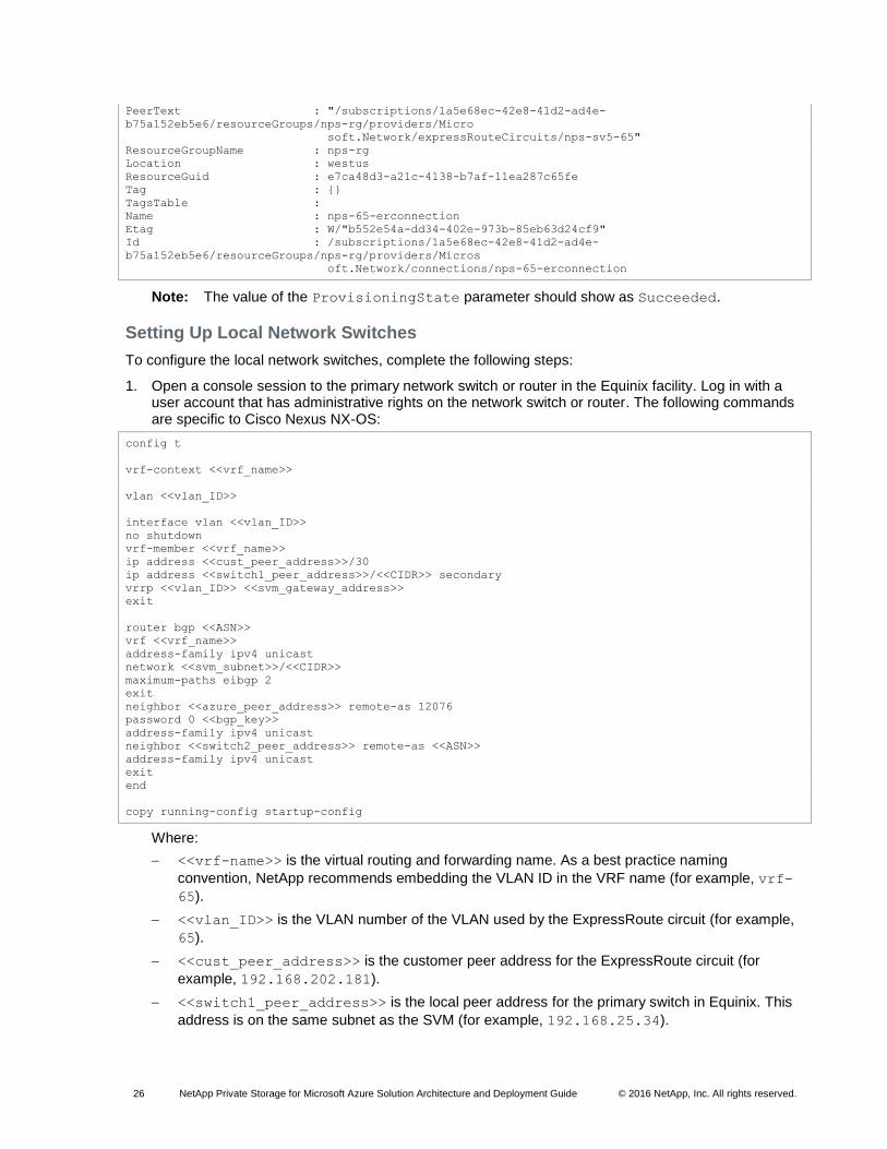
Note: The value of the ProvisioningState parameter should show as Succeeded.
Setting Up Local Network Switches
To configure the local network switches, complete the following steps:
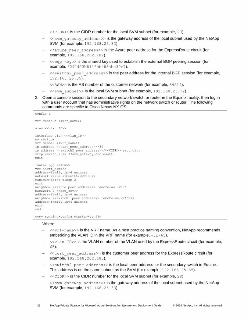
1. Open a console session to the primary network switch or router in the Equinix facility. Log in with a user account that has administrative rights on the network switch or router. The following commands are specific to Cisco Nexus NX-OS:
config t
vrf-context <<vrf_name>>
vlan <<vlan_ID>>
interface vlan <<vlan_ID>>
no shutdown
vrf-member <<vrf_name>>
ip address <<cust_peer_address>>/30
ip address <<switch1_peer_address>>/<<CIDR>> secondary
vrrp <<vlan_ID>> <<svm_gateway_address>>
exit
router bgp <<ASN>>
vrf <<vrf_name>>
address-family ipv4 unicast
network <<svm_subnet>>/<<CIDR>>
maximum-paths eibgp 2
exit
neighbor <<azure_peer_address>> remote-as 12076
password 0 <<bgp_key>>
address-family ipv4 unicast
neighbor <<switch2_peer_address>> remote-as <<ASN>>
address-family ipv4 unicast
exit
end
copy running-config startup-config
Where:
<<vrf-name>> is the virtual routing and forwarding name. As a best practice naming
convention, NetApp recommends embedding the VLAN ID in the VRF name (for example, vrf-
65).
<<vlan_ID>> is the VLAN number of the VLAN used by the ExpressRoute circuit (for example,
65).
<<cust_peer_address>> is the customer peer address for the ExpressRoute circuit (for
example, 192.168.202.181).
<<switch1_peer_address>> is the local peer address for the primary switch in Equinix. This
address is on the same subnet as the SVM (for example, 192.168.25.34).
27 NetApp Private Storage for Microsoft Azure Solution Architecture and Deployment Guide © 2016 NetApp, Inc. All rights reserved.
<<CIDR>> is the CIDR number for the local SVM subnet (for example, 28).
<<svm_gateway_address>> is the gateway address of the local subnet used by the NetApp
SVM (for example, 192.168.25.33).
<<azure_peer_address>> is the Azure peer address for the ExpressRoute circuit (for
example, 192.168.202.182).
<<bgp_key>> is the shared key used to establish the external BGP peering session (for
example, f291423b811fcb483aba30e7).
<<switch2_peer_address>> is the peer address for the internal BGP session (for example,
192.168.25.35).
<<ASN>> is the AS number of the customer network (for example, 64514).
<<svm_subnet>> is the local SVM subnet (for example, 192.168.25.32).
2. Open a console session to the secondary network switch or router in the Equinix facility, then log in with a user account that has administrative rights on the network switch or router. The following commands are specific to Cisco Nexus NX-OS:
config t
vrf-context <<vrf_name>>
vlan <<vlan_ID>>
interface vlan <<vlan_ID>>
no shutdown
vrf-member <<vrf_name>>
ip address <<cust_peer_address>>/30
ip address <<switch2_peer_address>>/<<CIDR>> secondary
vrrp <<vlan_ID>> <<svm_gateway_address>>
exit
router bgp <<ASN>>
vrf <<vrf_name>>
address-family ipv4 unicast
network <<svm_subnet>>/<<CIDR>>
maximum-paths eibgp 2
exit
neighbor <<azure_peer_address>> remote-as 12076
password 0 <<bgp_key>>
address-family ipv4 unicast
neighbor <<switch1_peer_address>> remote-as <<ASN>>
address-family ipv4 unicast
exit
end
copy running-config startup-config
Where:
<<vrf-name>> is the VRF name. As a best practice naming convention, NetApp recommends
embedding the VLAN ID in the VRF name (for example, vrf-65).
<<vlan_ID>> is the VLAN number of the VLAN used by the ExpressRoute circuit (for example,
65).
<<cust_peer_address>> is the customer peer address for the ExpressRoute circuit (for
example, 192.168.202.185).
<<switch2_peer_address>> is the local peer address for the secondary switch in Equinix.
This address is on the same subnet as the SVM (for example, 192.168.25.35).
<<CIDR>> is the CIDR number for the local SVM subnet (for example, 28).
<<svm_gateway_address>> is the gateway address of the local subnet used by the NetApp
SVM (for example, 192.168.25.33).
28 NetApp Private Storage for Microsoft Azure Solution Architecture and Deployment Guide © 2016 NetApp, Inc. All rights reserved.
Note: This IP address is the same IP address as on the primary switch.
<<azure_peer_address>> is the Azure peer address for the ExpressRoute circuit (for
example, 192.168.202.186).
<<bgp_key>> is the shared key used to establish the external BGP peering session (for
example, f291423b811fcb483aba30e7).
<<switch1_peer_address>> is the peer address for the internal BGP session (for example,
192.168.25.34).
<<ASN>> is the AS number of the customer network (for example, 64514).
<<svm_subnet>> is the local SVM subnet (for example, 192.168.25.32).
Configuring NetApp Storage
Note: Obtain the information from the NPS IP address plan in Table 1.
To configure the NetApp storage, complete the followings steps:
1. Create VLAN interface ports on cluster nodes using the same VLAN number as the ExpressRoute
circuit (for example, e0e-65).
2. Create a SVM on the cluster.
3. Create LIFs on the SVM that uses the VLAN interface ports. The IP addresses used are part of the
SVM network (192.168.25.32/28):
a. Management LIF (for example, 192.168.25.36/28)
b. CIFS/NFS LIF (for example, 192.168.25.37/28)
c. iSCSI LIF (one per cluster node: 192.168.25.38/28, 192.168.25.39/28, and so on)
3.3 Validation
Testing Connections and Protocol Access
Perform the procedures listed in this section to verify and test the ExpressRoute network connection and
in the NetApp Private Storage for Microsoft Azure environment.
Preparing Azure VM Instance
To prepare the Azure VM instance, complete the following steps:
1. From an Internet-connected host, launch a web browser and go to the Azure Portal.
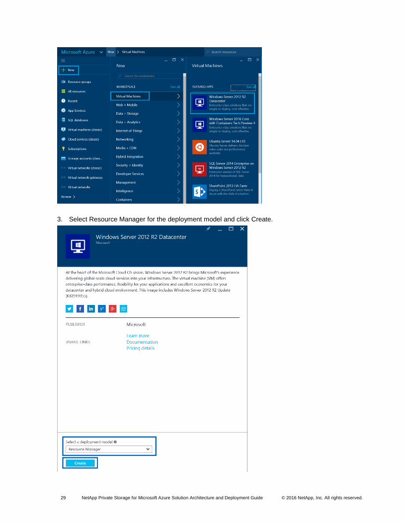
2. In the Azure Portal, click New > Virtual Machine and select the virtual machine type you want to launch. This example uses Windows Server 2012 R2 Datacenter.
29 NetApp Private Storage for Microsoft Azure Solution Architecture and Deployment Guide © 2016 NetApp, Inc. All rights reserved.
3. Select Resource Manager for the deployment model and click Create.
30 NetApp Private Storage for Microsoft Azure Solution Architecture and Deployment Guide © 2016 NetApp, Inc. All rights reserved.
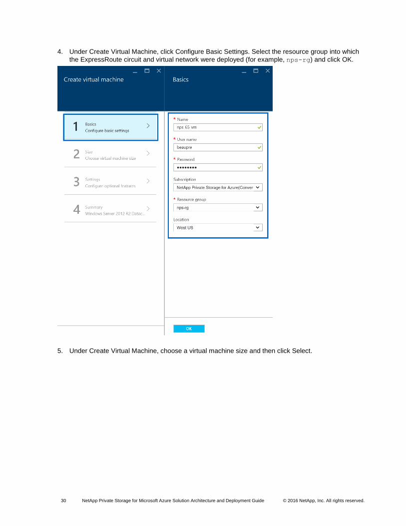
4. Under Create Virtual Machine, click Configure Basic Settings. Select the resource group into which
the ExpressRoute circuit and virtual network were deployed (for example, nps-rg) and click OK.
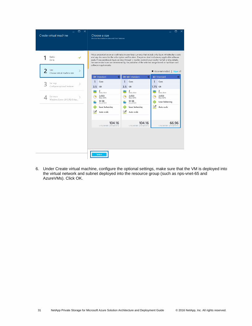
5. Under Create Virtual Machine, choose a virtual machine size and then click Select.
31 NetApp Private Storage for Microsoft Azure Solution Architecture and Deployment Guide © 2016 NetApp, Inc. All rights reserved.
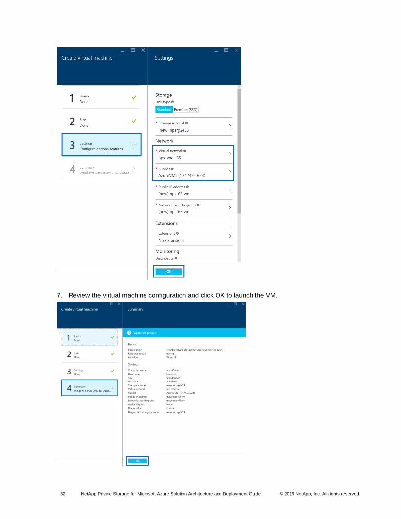
6. Under Create virtual machine, configure the optional settings, make sure that the VM is deployed into the virtual network and subnet deployed into the resource group (such as nps-vnet-65 and AzureVMs). Click OK.
32 NetApp Private Storage for Microsoft Azure Solution Architecture and Deployment Guide © 2016 NetApp, Inc. All rights reserved.
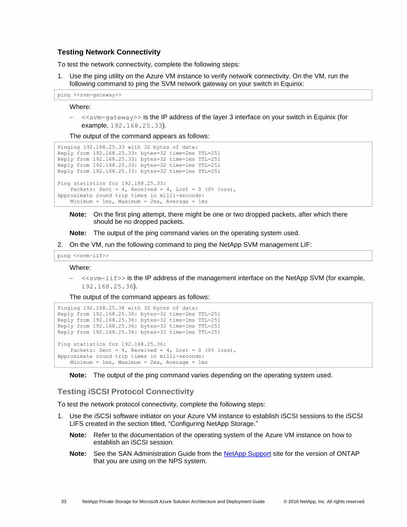
7. Review the virtual machine configuration and click OK to launch the VM.
33 NetApp Private Storage for Microsoft Azure Solution Architecture and Deployment Guide © 2016 NetApp, Inc. All rights reserved.
Testing Network Connectivity
To test the network connectivity, complete the following steps:
1. Use the ping utility on the Azure VM instance to verify network connectivity. On the VM, run the following command to ping the SVM network gateway on your switch in Equinix:
ping <<svm-gateway>>
Where:
<<svm-gateway>> is the IP address of the layer 3 interface on your switch in Equinix (for
example, 192.168.25.33).
The output of the command appears as follows:
Pinging 192.168.25.33 with 32 bytes of data:
Reply from 192.168.25.33: bytes=32 time=2ms TTL=251
Reply from 192.168.25.33: bytes=32 time=1ms TTL=251
Reply from 192.168.25.33: bytes=32 time=1ms TTL=251
Reply from 192.168.25.33: bytes=32 time=1ms TTL=251
Ping statistics for 192.168.25.33:
Packets: Sent = 4, Received = 4, Lost = 0 (0% loss),
Approximate round trip times in milli-seconds:
Minimum = 1ms, Maximum = 2ms, Average = 1ms
Note: On the first ping attempt, there might be one or two dropped packets, after which there should be no dropped packets.
Note: The output of the ping command varies on the operating system used.
2. On the VM, run the following command to ping the NetApp SVM management LIF:
ping <<svm-lif>>
Where:
<<svm-lif>> is the IP address of the management interface on the NetApp SVM (for example,
192.168.25.36).
The output of the command appears as follows:
Pinging 192.168.25.36 with 32 bytes of data:
Reply from 192.168.25.36: bytes=32 time=2ms TTL=251
Reply from 192.168.25.36: bytes=32 time=1ms TTL=251
Reply from 192.168.25.36: bytes=32 time=1ms TTL=251
Reply from 192.168.25.36: bytes=32 time=1ms TTL=251
Ping statistics for 192.168.25.36:
Packets: Sent = 4, Received = 4, Lost = 0 (0% loss),
Approximate round trip times in milli-seconds:
Minimum = 1ms, Maximum = 2ms, Average = 1ms
Note: The output of the ping command varies depending on the operating system used.
Testing iSCSI Protocol Connectivity
To test the network protocol connectivity, complete the following steps:
1. Use the iSCSI software initiator on your Azure VM instance to establish iSCSI sessions to the iSCSI LIFS created in the section titled, “Configuring NetApp Storage.”
Note: Refer to the documentation of the operating system of the Azure VM instance on how to establish an iSCSI session.
Note: See the SAN Administration Guide from the NetApp Support site for the version of ONTAP that you are using on the NPS system.
34 NetApp Private Storage for Microsoft Azure Solution Architecture and Deployment Guide © 2016 NetApp, Inc. All rights reserved.
2. The successful outcome of the test is that an iSCSI session is successfully established from the iSCSI software initiator on the Azure VM instance to the iSCSI LIF on the NPS.
Verifying iSCSI LUN Access
To verify iSCSI LUN access, complete the following steps:
1. From a local administration host or from the Azure VM instance, create an aggregate, flexible volume, LUN, and igroup using the ONTAP CLI or NetApp OnCommand® System Manager software.
Note: The commands and/or workflows to create these storage primitives depend on the version of ONTAP used on the NPS system.
Note: See the SAN Administration Guide from the NetApp Support site for the version of ONTAP that you are using on the NPS system.
2. After configuring the NetApp storage, use iSCSI tools on the Azure VM instance to discover the iSCSI LUN (such as iscsiadm, Windows ISCSI control panel application, and so on).
Note: Refer to the documentation of the operating system of the Azure VM instance on how to discover the iSCSI LUN.
3. After the iSCSI LUN has been discovered by the Azure VM instance, create a file system on the LUN and mount the file system.
Note: Refer to the documentation of the operating system of the Azure VM instance on how to discover the iSCSI LUN.
4. Use the CD utility on your Azure VM instance connected to the iSCSI LUN. Write a text file and save it to the iSCSI LUN.
Note: Refer to the documentation of the operating system of the Azure VM instance on how to write and save a file.
5. The successful outcome of this test is that you will be able to access the LUN file system and write a file to it.
Verifying SMB Protocol Connectivity
To verify SMB protocol connectivity, complete the following steps:
1. To perform this test, you need an Azure VM instance running the Windows operating system deployed to the Azure VNet that is connected to the ExpressRoute circuit. If you do not have a Windows VM instance deployed, deploy one before proceeding to step 2.
2. From a local administration host or from the Azure VM instance, create a flexible volume and junction point on the NPS system.
Note: Refer to the File Access Management Guide for CIFS from the NetApp Support site for the version of ONTAP that you are using on the NPS system.
3. After creating the SMB share, use the Azure VM instance to access the share. Write a text file and save it to the SMB share.
4. The successful outcome of this test is that you will be able to access the SMB share and write a file to it.
Verifying NFS Protocol Connectivity
To verify NFS protocol connectivity, complete the following steps:
1. To perform this test, you need an Azure VM instance running the Linux operating system deployed to the Azure VNet that is connected to the ExpressRoute circuit. If you do not have a Linux VM instance deployed, deploy one before proceeding to step 2.
35 NetApp Private Storage for Microsoft Azure Solution Architecture and Deployment Guide © 2016 NetApp, Inc. All rights reserved.
2. From a local administration host or from the Linux VM instance, create a flexible volume and junction point on the NPS system.
Note: Refer to the File Access Management Guide for NFS on the NetApp Support site for the version of ONTAP that you are using on the NPS system.
3. After creating the NFS export, use the Azure VM instance to mount the export. Write a text file and save it to the NFS export.
4. The successful outcome for this test is that you will be able to access the NFS export and write a file to it.
Testing AutoSupport
For NetApp AutoSupport® to work, the NetApp storage must have access to the Internet or to a mail host
that has access to the Internet. You can accomplish this in one of the following ways:
Set up a mail host in the Azure VNet that is connected to the storage.
Set up a network connection to the Internet in the colocation where the storage is located.
Set up a network connection on premises over a VPN or MPLS connection.
Note: Refer to the System Administration Guide from the NetApp Support site for the version of ONTAP that you are using on the NPS system.
Performance Test Guidelines
The concepts underlying performance testing with NetApp Private Storage for Microsoft Azure are similar
to those for performance testing in environments. The following sections describe considerations to take
into account when conducting performance testing in the NetApp Private Storage for Microsoft Azure
solution environment.
Understanding Goals of Performance Testing
Performance tests are used to validate the performance of the storage, network, and computing
resources, given a specific workload that is an estimate of a real-world workload.
All architectures have limits to their performance. The goal of performance testing is not to see how much
load you can put in the environment before things break, but to follow an iterative, deliberate process that
results in data that can be plotted and analyzed so that architects can anticipate performance based on a
given workload (that is, performance curves).
NetApp Storage Considerations for Performance Testing
The considerations for sizing NetApp storage are the same in the NetApp Private Storage for Microsoft
Azure solution architecture as in typical deployments of NetApp storage. NetApp storage requires the
following considerations:
Number and type of NetApp controllers. Are the number and type of controllers used in the testing appropriate for the performance testing?
Number and type of disks in the aggregates. Do the number and types of disks in the aggregate used in the testing have enough IOPS and storage capacity for the testing?
Flash Cache. Are Flash Cache™ adapters installed in the storage controller nodes?
Cluster node network connectivity. What is the bandwidth of network connections (1GbE or 10GbE), and what is the number of connections used to connect the storage to the network equipment in the colocation facility that is connected to the Azure cloud?
36 NetApp Private Storage for Microsoft Azure Solution Architecture and Deployment Guide © 2016 NetApp, Inc. All rights reserved.
Network Equipment Considerations for Performance Testing
The considerations for the network equipment in the NetApp Private Storage for Microsoft Azure solution
architecture are the same as those in typical network environments. The network equipment requires the
following considerations:
Available CPU and memory. Does the switch that is being used have enough resources to support the performance testing? Adding additional workload to an oversubscribed network switch might contribute to invalid performance testing results.
Network ports used. What is the bandwidth of network connections (200Mbps, 500Mbps, or 1Gbps), and what is the number of connections used to connect to the storage and to Azure? Is enough bandwidth available to accommodate a performance test?
Microsoft Azure Considerations for Performance Testing
It is very important to understand how the components of the Azure cloud can affect performance testing.
The following considerations apply to the Azure cloud:
Azure ExpressRoute network connection. Is there enough bandwidth available to accommodate performance testing? Contention for network bandwidth can affect performance testing results. Be sure that there is enough network bandwidth to support the testing.
Azure VM instance type. Verify that you are using the proper instance type for performance testing. Azure throttles network throughput for smaller instance types and allocates more network for larger network types. Having the correct instance type is critical for a successful performance test. For more information about instance types, refer to Virtual Machine and Cloud Service Sizes for Azure in the Microsoft Azure documentation.
Load-Generation and Monitoring Tools Used for Performance Testing
The load-generation and monitoring tools used for performance testing with the NetApp Private Storage
for Microsoft Azure solution architecture are the same as those used for typical NetApp storage
environments. Here are some considerations on the tools and monitoring used for performance testing:
Know what tool you will use. Each tool has advantages and disadvantages. Understanding the correct tool for your performance testing can provide more accurate test results.
Know your workload. What kind of workload will you be testing? Understanding the I/O patterns of the workloads you are testing helps make it possible to configure the load-generation tool correctly so that the testing can accurately model the performance.
Monitor the stack. Implement monitoring for the computing, network, and storage resources so that bottlenecks can be identified. Collect performance data from each stack so that analysis can provide a more complete picture of how the NetApp Private Storage for Microsoft Azure solution architecture is performing.
4 Azure Government
Microsoft Azure Government consists of two Azure regions: U.S. government Iowa and U.S. government
Virginia. These regions are completely separated from all other Azure regions. Azure Government is used
by the U.S. government agencies to run workloads and services in the Azure cloud subject to the strict
compliance requirements of the U.S. government. For more information, see the Azure Government
documentation.
Azure ExpressRoute connectivity to the Azure government regions is available in the Equinix Chicago
and Equinix Ashburn (Washington, D.C.) data centers. Customers can also connect to Azure Government
from their on-premises data centers using point-to-point network links provided by Level 3
Communications. For more information, see the Azure Government ExpressRoute for Microsoft Azure
Government data sheet.
37 NetApp Private Storage for Microsoft Azure Solution Architecture and Deployment Guide © 2016 NetApp, Inc. All rights reserved.
The functionality of the ExpressRoute service in the Azure Government regions is similar to the
functionality of ExpressRoute in the other commercial Azure regions. There are public, private, and
Microsoft ExpressRoute circuits. The workflows to create and configure them are the same as the
ExpressRoute workflows in the other Azure commercial regions.
Note: Azure Government uses Service Management cmdlets and the classic Azure Portal.
The Federal Risk and Authorization Management Program (FedRAMP) does not directly affect the
technical aspects of the solution, but it does affect the ability of the solution to be deployed and managed.
Note: The International Traffic in Arms Regulations (ITAR) boundary for Azure ExpressRoute is not specifically defined by the Microsoft Azure Government documentation. If you have an ITAR requirement for your solution, contact your NetApp account team for further assistance.
The use cases for NetApp Private Storage for Azure are also valid for NetApp Private Storage in the
Azure Government regions.
4.1 Deployment Considerations for NPS for Azure Government
Although the Azure Government regions are very similar in functionality to Azure commercial regions,
there are differences that must be considered when deploying NPS for Azure Government.
The high-level deployment workflow for NPS for Azure Government consists of the following phases and
tasks:
1. Planning:
a. Setting up an Azure Government subscription
b. Planning the IP address
c. Installing Azure PowerShell service management modules
2. Deployment:
a. Installing the equipment in the Equinix data center
b. Setting up the Azure VNet
c. Setting up the Azure ExpressRoute circuit
d. Setting up the network switch
e. Configuring the NetApp storage
f. Testing the connections and protocols access
Note: These steps are similar to those for an NPS deployment using an Azure commercial region. This section contains the additional steps required to deploy NPS with Azure Government.
4.2 Planning
Setting Up Azure Government Subscription
Only U.S. citizens are authorized to access or use Azure Government resources. For more information
about how to order an Azure Government subscription, see the Azure Government documentation.
After you have the Azure Government subscription, open a support request with Microsoft support to
enable ExpressRoute direct connections on the subscription.
Planning IP Address
The IP address plan for Azure Government is the same as the IP address plan for Azure commercial
regions. For more information about the IP address plan, see section 3.1.
38 NetApp Private Storage for Microsoft Azure Solution Architecture and Deployment Guide © 2016 NetApp, Inc. All rights reserved.
Installing Azure PowerShell Service Management Modules
As noted earlier in this section, Azure Government regions use Azure PowerShell Service Management
cmdlets.
To install the Azure Service Management PowerShell modules, run the following command from an
Internet-connected Windows 8 or Windows 2012 (or later) computer:
Install-Module Azure
To import the Azure on which the Azure Service Management PowerShell modules were installed, run the
following commands:
Import-Module 'C:\Program Files (x86)\Microsoft
SDKs\Azure\PowerShell\ServiceManagement\Azure\Azure.psd1'
Import-Module 'C:\Program Files (x86)\Microsoft
SDKs\Azure\PowerShell\ServiceManagement\Azure\ExpressRoute\ExpressRoute.psd1'
To import the Azure Service Management PowerShell modules when you start a PowerShell session, run
the following command:
notepad $profile
If the PowerShell profile file does not exist, you will be prompted to create one. In Notepad, copy the
commands used to import the Azure Service Management PowerShell modules. Save the file.
For more information about how to install and configure Azure PowerShell modules, see the Azure
PowerShell documentation.
4.3 Deployment
Installing Equipment in Equinix Data Center
You can install the equipment in the data center after the preinstallation and site preparation phase is
complete.
To set up the data center, complete the following steps:
1. Set up security access to the Equinix data center and cage.
2. Make sure that the required materials (hardware, software, and accessories) are on site.
3. Install the NetApp storage, customer-provided network equipment, and accessories in the rack.
Setting Up Azure VNet
Note: A Microsoft account associated with the Azure Government subscription and Azure PowerShell modules installed on an Internet-connected computer are required.
Note: For the VPC configuration parameters, refer to the NPS for Azure Government IP address plan.
To set up the Azure VNet, complete the following steps:
1. On the Windows host where the PowerShell commands were installed, log in to Azure by running the following command:
Login-AzureRmAccount
2. When prompted by Azure, enter the user name and password for the work or school account or the Microsoft account associated with your Azure Government subscription. Click Sign In to continue.
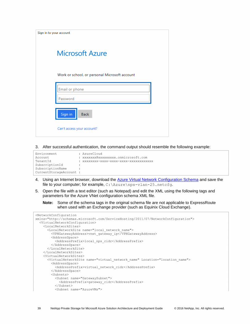
39 NetApp Private Storage for Microsoft Azure Solution Architecture and Deployment Guide © 2016 NetApp, Inc. All rights reserved.
3. After successful authentication, the command output should resemble the following example:
Environment : AzureCloud
Account : [email protected]
TenantId : xxxxxxxx-xxxx-xxxx-xxxx-xxxxxxxxxxxx
SubscriptionId :
SubscriptionName :
CurrentStorageAccount :
4. Using an Internet browser, download the Azure Virtual Network Configuration Schema and save the
file to your computer; for example, C:\Azure\nps-vlan-25.netcfg.
5. Open the file with a text editor (such as Notepad) and edit the XML using the following tags and parameters for the Azure VNet configuration schema XML file.
Note: Some of the schema tags in the original schema file are not applicable to ExpressRoute when used with an Exchange provider (such as Equinix Cloud Exchange).
<NetworkConfiguration
xmlns="http://schemas.microsoft.com/ServiceHosting/2011/07/NetworkConfiguration">
<VirtualNetworkConfiguration>
<LocalNetworkSites>
<LocalNetworkSite name="local_network_name">
<VPNGatewayAddress>vnet_gateway_ip</VPNGatewayAddress>
<AddressSpace>
<AddressPrefix>local_nps_cidr</AddressPrefix>
</AddressSpace>
</LocalNetworkSite>
</LocalNetworkSites>
<VirtualNetworkSites>
<VirtualNetworkSite name="virtual_network_name" Location="location_name">
<AddressSpace>
<AddressPrefix>virtual_network_cidr</AddressPrefix>
</AddressSpace>
<Subnets>
<Subnet name="GatewaySubnet">
<AddressPrefix>gateway_cidr</AddressPrefix>
</Subnet>
<Subnet name="AzureVMs">
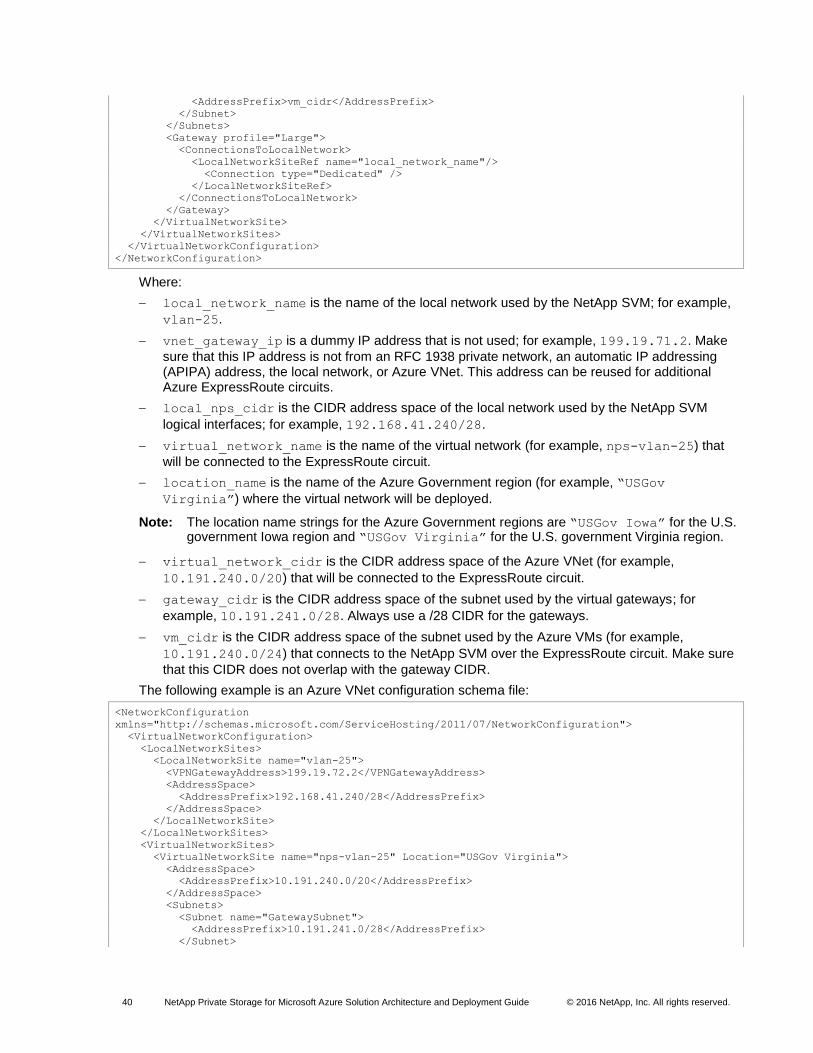
40 NetApp Private Storage for Microsoft Azure Solution Architecture and Deployment Guide © 2016 NetApp, Inc. All rights reserved.
<AddressPrefix>vm_cidr</AddressPrefix>
</Subnet>
</Subnets>
<Gateway profile="Large">
<ConnectionsToLocalNetwork>
<LocalNetworkSiteRef name="local_network_name"/>
<Connection type="Dedicated" />
</LocalNetworkSiteRef>
</ConnectionsToLocalNetwork>
</Gateway>
</VirtualNetworkSite>
</VirtualNetworkSites>
</VirtualNetworkConfiguration>
</NetworkConfiguration>
Where:
local_network_name is the name of the local network used by the NetApp SVM; for example,
vlan-25.
vnet_gateway_ip is a dummy IP address that is not used; for example, 199.19.71.2. Make
sure that this IP address is not from an RFC 1938 private network, an automatic IP addressing (APIPA) address, the local network, or Azure VNet. This address can be reused for additional Azure ExpressRoute circuits.
local_nps_cidr is the CIDR address space of the local network used by the NetApp SVM
logical interfaces; for example, 192.168.41.240/28.
virtual_network_name is the name of the virtual network (for example, nps-vlan-25) that
will be connected to the ExpressRoute circuit.
location_name is the name of the Azure Government region (for example, “USGov
Virginia”) where the virtual network will be deployed.
Note: The location name strings for the Azure Government regions are “USGov Iowa” for the U.S. government Iowa region and “USGov Virginia” for the U.S. government Virginia region.
virtual_network_cidr is the CIDR address space of the Azure VNet (for example,
10.191.240.0/20) that will be connected to the ExpressRoute circuit.
gateway_cidr is the CIDR address space of the subnet used by the virtual gateways; for
example, 10.191.241.0/28. Always use a /28 CIDR for the gateways.
vm_cidr is the CIDR address space of the subnet used by the Azure VMs (for example,
10.191.240.0/24) that connects to the NetApp SVM over the ExpressRoute circuit. Make sure
that this CIDR does not overlap with the gateway CIDR.
The following example is an Azure VNet configuration schema file:
<NetworkConfiguration
xmlns="http://schemas.microsoft.com/ServiceHosting/2011/07/NetworkConfiguration">
<VirtualNetworkConfiguration>
<LocalNetworkSites>
<LocalNetworkSite name="vlan-25">
<VPNGatewayAddress>199.19.72.2</VPNGatewayAddress>
<AddressSpace>
<AddressPrefix>192.168.41.240/28</AddressPrefix>
</AddressSpace>
</LocalNetworkSite>
</LocalNetworkSites>
<VirtualNetworkSites>
<VirtualNetworkSite name="nps-vlan-25" Location="USGov Virginia">
<AddressSpace>
<AddressPrefix>10.191.240.0/20</AddressPrefix>
</AddressSpace>
<Subnets>
<Subnet name="GatewaySubnet">
<AddressPrefix>10.191.241.0/28</AddressPrefix>
</Subnet>
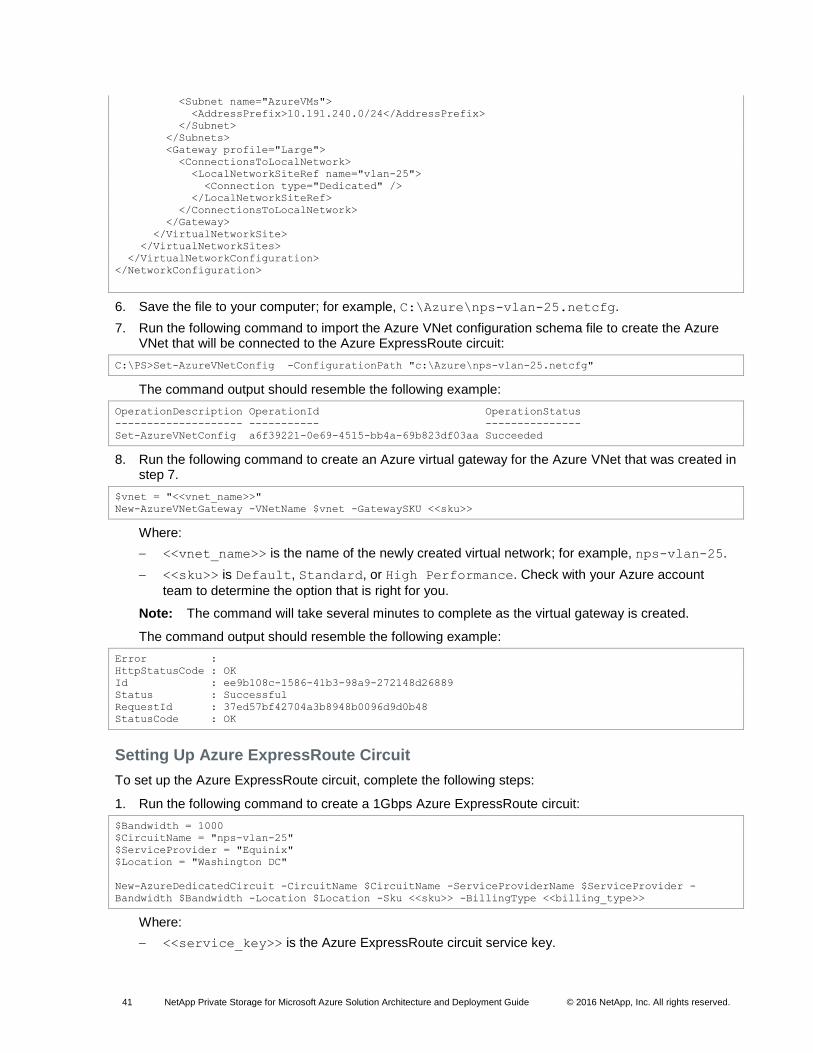
41 NetApp Private Storage for Microsoft Azure Solution Architecture and Deployment Guide © 2016 NetApp, Inc. All rights reserved.
<Subnet name="AzureVMs">
<AddressPrefix>10.191.240.0/24</AddressPrefix>
</Subnet>
</Subnets>
<Gateway profile="Large">
<ConnectionsToLocalNetwork>
<LocalNetworkSiteRef name="vlan-25">
<Connection type="Dedicated" />
</LocalNetworkSiteRef>
</ConnectionsToLocalNetwork>
</Gateway>
</VirtualNetworkSite>
</VirtualNetworkSites>
</VirtualNetworkConfiguration>
</NetworkConfiguration>
6. Save the file to your computer; for example, C:\Azure\nps-vlan-25.netcfg.
7. Run the following command to import the Azure VNet configuration schema file to create the Azure VNet that will be connected to the Azure ExpressRoute circuit:
C:\PS>Set-AzureVNetConfig -ConfigurationPath "c:\Azure\nps-vlan-25.netcfg"
The command output should resemble the following example:
OperationDescription OperationId OperationStatus
-------------------- ----------- ---------------
Set-AzureVNetConfig a6f39221-0e69-4515-bb4a-69b823df03aa Succeeded
8. Run the following command to create an Azure virtual gateway for the Azure VNet that was created in step 7.
$vnet = "<<vnet_name>>"
New-AzureVNetGateway -VNetName $vnet -GatewaySKU <<sku>>
Where:
<<vnet_name>> is the name of the newly created virtual network; for example, nps-vlan-25.
<<sku>> is Default, Standard, or High Performance. Check with your Azure account
team to determine the option that is right for you.
Note: The command will take several minutes to complete as the virtual gateway is created.
The command output should resemble the following example:
Error :
HttpStatusCode : OK
Id : ee9b108c-1586-41b3-98a9-272148d26889
Status : Successful
RequestId : 37ed57bf42704a3b8948b0096d9d0b48
StatusCode : OK
Setting Up Azure ExpressRoute Circuit
To set up the Azure ExpressRoute circuit, complete the following steps:
1. Run the following command to create a 1Gbps Azure ExpressRoute circuit:
$Bandwidth = 1000
$CircuitName = "nps-vlan-25"
$ServiceProvider = "Equinix"
$Location = "Washington DC"
New-AzureDedicatedCircuit -CircuitName $CircuitName -ServiceProviderName $ServiceProvider -
Bandwidth $Bandwidth -Location $Location -Sku <<sku>> -BillingType <<billing_type>>
Where:
<<service_key>> is the Azure ExpressRoute circuit service key.
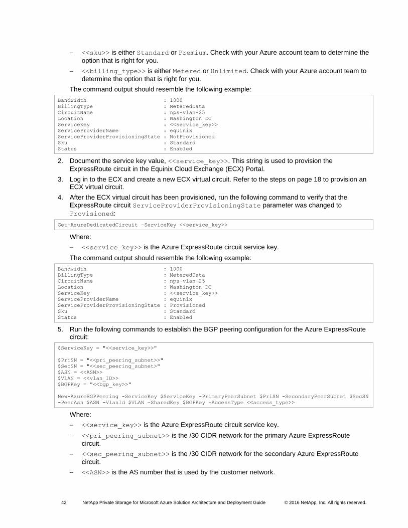
42 NetApp Private Storage for Microsoft Azure Solution Architecture and Deployment Guide © 2016 NetApp, Inc. All rights reserved.
<<sku>> is either Standard or Premium. Check with your Azure account team to determine the
option that is right for you.
<<billing_type>> is either Metered or Unlimited. Check with your Azure account team to
determine the option that is right for you.
The command output should resemble the following example:
Bandwidth : 1000
BillingType : MeteredData
CircuitName : nps-vlan-25
Location : Washington DC
ServiceKey : <<service_key>>
ServiceProviderName : equinix
ServiceProviderProvisioningState : NotProvisioned
Sku : Standard
Status : Enabled
2. Document the service key value, <<service_key>>. This string is used to provision the
ExpressRoute circuit in the Equinix Cloud Exchange (ECX) Portal.
3. Log in to the ECX and create a new ECX virtual circuit. Refer to the steps on page 18 to provision an ECX virtual circuit.
4. After the ECX virtual circuit has been provisioned, run the following command to verify that the
ExpressRoute circuit ServiceProviderProvisioningState parameter was changed to
Provisioned:
Get-AzureDedicatedCircuit -ServiceKey <<service_key>>
Where:
<<service_key>> is the Azure ExpressRoute circuit service key.
The command output should resemble the following example:
Bandwidth : 1000
BillingType : MeteredData
CircuitName : nps-vlan-25
Location : Washington DC
ServiceKey : <<service_key>>
ServiceProviderName : equinix
ServiceProviderProvisioningState : Provisioned
Sku : Standard
Status : Enabled
5. Run the following commands to establish the BGP peering configuration for the Azure ExpressRoute circuit:
$ServiceKey = "<<service_key>>"
$PriSN = "<<pri_peering_subnet>>"
$SecSN = "<<sec_peering_subnet>"
$ASN = <<ASN>>
$VLAN = <<vlan_ID>>
$BGPKey = "<<bgp_key>>"
New-AzureBGPPeering -ServiceKey $ServiceKey -PrimaryPeerSubnet $PriSN -SecondaryPeerSubnet $SecSN
-PeerAsn $ASN -VlanId $VLAN –SharedKey $BGPKey –AccessType <<access_type>>
Where:
<<service_key>> is the Azure ExpressRoute circuit service key.
<<pri_peering_subnet>> is the /30 CIDR network for the primary Azure ExpressRoute
circuit.
<<sec_peering_subnet>> is the /30 CIDR network for the secondary Azure ExpressRoute
circuit.
<<ASN>> is the AS number that is used by the customer network.
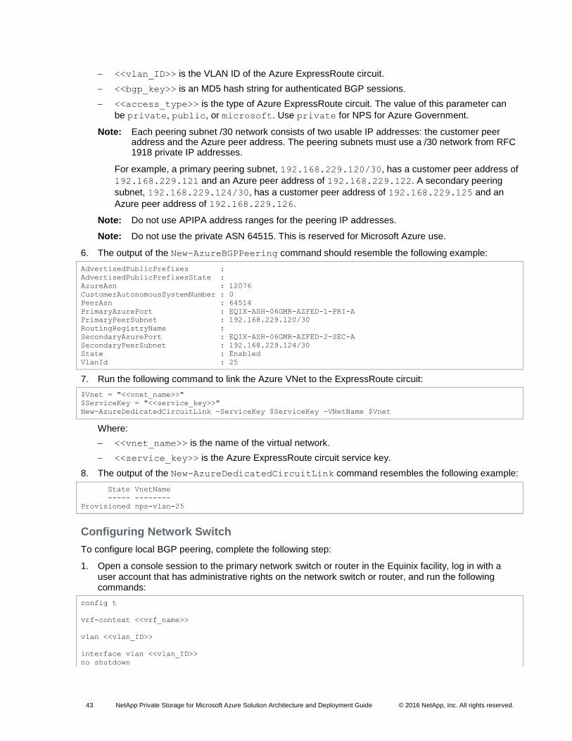
43 NetApp Private Storage for Microsoft Azure Solution Architecture and Deployment Guide © 2016 NetApp, Inc. All rights reserved.
<<vlan_ID>> is the VLAN ID of the Azure ExpressRoute circuit.
<<bgp_key>> is an MD5 hash string for authenticated BGP sessions.
<<access_type>> is the type of Azure ExpressRoute circuit. The value of this parameter can
be private, public, or microsoft. Use private for NPS for Azure Government.
Note: Each peering subnet /30 network consists of two usable IP addresses: the customer peer address and the Azure peer address. The peering subnets must use a /30 network from RFC 1918 private IP addresses.
For example, a primary peering subnet, 192.168.229.120/30, has a customer peer address of
192.168.229.121 and an Azure peer address of 192.168.229.122. A secondary peering
subnet, 192.168.229.124/30, has a customer peer address of 192.168.229.125 and an
Azure peer address of 192.168.229.126.
Note: Do not use APIPA address ranges for the peering IP addresses.
Note: Do not use the private ASN 64515. This is reserved for Microsoft Azure use.
6. The output of the New-AzureBGPPeering command should resemble the following example:
AdvertisedPublicPrefixes :
AdvertisedPublicPrefixesState :
AzureAsn : 12076
CustomerAutonomousSystemNumber : 0
PeerAsn : 64514
PrimaryAzurePort : EQIX-ASH-06GMR-AZFED-1-PRI-A
PrimaryPeerSubnet : 192.168.229.120/30
RoutingRegistryName :
SecondaryAzurePort : EQIX-ASH-06GMR-AZFED-2-SEC-A
SecondaryPeerSubnet : 192.168.229.124/30
State : Enabled
VlanId : 25
7. Run the following command to link the Azure VNet to the ExpressRoute circuit:
$Vnet = "<<vnet_name>>"
$ServiceKey = "<<service_key>>"
New-AzureDedicatedCircuitLink -ServiceKey $ServiceKey -VNetName $Vnet
Where:
<<vnet_name>> is the name of the virtual network.
<<service_key>> is the Azure ExpressRoute circuit service key.
8. The output of the New-AzureDedicatedCircuitLink command resembles the following example:
State VnetName
----- --------
Provisioned nps-vlan-25
Configuring Network Switch
To configure local BGP peering, complete the following step:
1. Open a console session to the primary network switch or router in the Equinix facility, log in with a user account that has administrative rights on the network switch or router, and run the following commands:
config t
vrf-context <<vrf_name>>
vlan <<vlan_ID>>
interface vlan <<vlan_ID>>
no shutdown
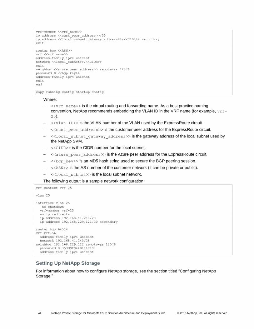
44 NetApp Private Storage for Microsoft Azure Solution Architecture and Deployment Guide © 2016 NetApp, Inc. All rights reserved.
vrf-member <<vrf_name>>
ip address <<cust_peer_address>>/30
ip address <<local_subnet_gateway_address>>/<<CIDR>> secondary
exit
router bgp <<ASN>>
vrf <<vrf_name>>
address-family ipv4 unicast
network <<local_subnet>>/<<CIDR>>
exit
neighbor <<azure_peer_address>> remote-as 12076
password 0 <<bgp_key>>
address-family ipv4 unicast
exit
end
copy running-config startup-config
Where:
<<vrf-name>> is the virtual routing and forwarding name. As a best practice naming
convention, NetApp recommends embedding the VLAN ID in the VRF name (for example, vrf-
25).
<<vlan_ID>> is the VLAN number of the VLAN used by the ExpressRoute circuit.
<<cust_peer_address>> is the customer peer address for the ExpressRoute circuit.
<<local_subnet_gateway_address>> is the gateway address of the local subnet used by
the NetApp SVM.
<<CIDR>> is the CIDR number for the local subnet.
<<azure_peer_address>> is the Azure peer address for the ExpressRoute circuit.
<<bgp_key>> is an MD5 hash string used to secure the BGP peering session.
<<ASN>> is the AS number of the customer network (it can be private or public).
<<local_subnet>> is the local subnet network.
The following output is a sample network configuration:
vrf context vrf-25
vlan 25
interface vlan 25
no shutdown
vrf-member vrf-25
no ip redirects
ip address 192.168.41.241/28
ip address 192.168.229.121/30 secondary
router bgp 64514
vrf vrf-56
address-family ipv4 unicast
network 192.168.41.240/28
neighbor 192.168.229.122 remote-as 12076
password 0 353d9f94481a1c19
address-family ipv4 unicast
Setting Up NetApp Storage
For information about how to configure NetApp storage, see the section titled “Configuring NetApp
Storage.”
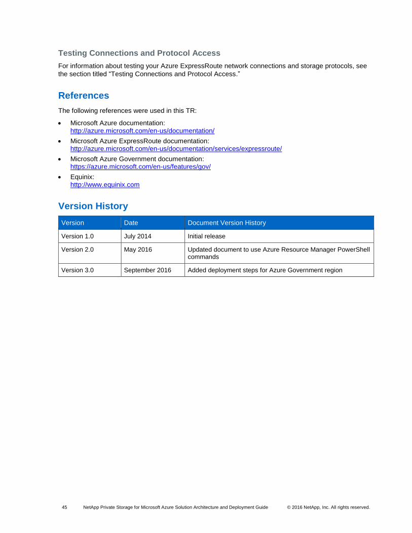
45 NetApp Private Storage for Microsoft Azure Solution Architecture and Deployment Guide © 2016 NetApp, Inc. All rights reserved.
Testing Connections and Protocol Access
For information about testing your Azure ExpressRoute network connections and storage protocols, see
the section titled “Testing Connections and Protocol Access.”
References
The following references were used in this TR:
Microsoft Azure documentation: http://azure.microsoft.com/en-us/documentation/
Microsoft Azure ExpressRoute documentation: http://azure.microsoft.com/en-us/documentation/services/expressroute/
Microsoft Azure Government documentation: https://azure.microsoft.com/en-us/features/gov/
Equinix: http://www.equinix.com
Version History
Version Date Document Version History
Version 1.0 July 2014 Initial release
Version 2.0 May 2016 Updated document to use Azure Resource Manager PowerShell commands
Version 3.0 September 2016 Added deployment steps for Azure Government region
46 NetApp Private Storage for Microsoft Azure Solution Architecture and Deployment Guide © 2016 NetApp, Inc. All rights reserved.
Refer to the Interoperability Matrix Tool (IMT) on the NetApp Support site to validate that the exact product and feature versions described in this document are supported for your specific environment. The NetApp IMT defines the product components and versions that can be used to construct configurations that are supported by NetApp. Specific results depend on each customer’s installation in accordance with published specifications.
Copyright Information
Copyright © 1994–2016 NetApp, Inc. All rights reserved. Printed in the U.S. No part of this document covered by copyright may be reproduced in any form or by any means—graphic, electronic, or mechanical, including photocopying, recording, taping, or storage in an electronic retrieval system—without prior written permission of the copyright owner.
Software derived from copyrighted NetApp material is subject to the following license and disclaimer:
THIS SOFTWARE IS PROVIDED BY NETAPP “AS IS” AND WITHOUT ANY EXPRESS OR IMPLIED WARRANTIES, INCLUDING, BUT NOT LIMITED TO, THE IMPLIED WARRANTIES OF MERCHANTABILITY AND FITNESS FOR A PARTICULAR PURPOSE, WHICH ARE HEREBY DISCLAIMED. IN NO EVENT SHALL NETAPP BE LIABLE FOR ANY DIRECT, INDIRECT, INCIDENTAL, SPECIAL, EXEMPLARY, OR CONSEQUENTIAL DAMAGES (INCLUDING, BUT NOT LIMITED TO, PROCUREMENT OF SUBSTITUTE GOODS OR SERVICES; LOSS OF USE, DATA, OR PROFITS; OR BUSINESS INTERRUPTION) HOWEVER CAUSED AND ON ANY THEORY OF LIABILITY, WHETHER IN CONTRACT, STRICT LIABILITY, OR TORT (INCLUDING NEGLIGENCE OR OTHERWISE) ARISING IN ANY WAY OUT OF THE USE OF THIS SOFTWARE, EVEN IF ADVISED OF THE POSSIBILITY OF SUCH DAMAGE.
NetApp reserves the right to change any products described herein at any time, and without notice. NetApp assumes no responsibility or liability arising from the use of products described herein, except as expressly agreed to in writing by NetApp. The use or purchase of this product does not convey a license under any patent rights, trademark rights, or any other intellectual property rights of NetApp.
The product described in this manual may be protected by one or more U.S. patents, foreign patents, or pending applications.
RESTRICTED RIGHTS LEGEND: Use, duplication, or disclosure by the government is subject to restrictions as set forth in subparagraph (c)(1)(ii) of the Rights in Technical Data and Computer Software clause at DFARS 252.277-7103 (October 1988) and FAR 52-227-19 (June 1987).
Trademark Information
NetApp, the NetApp logo, Go Further, Faster, AltaVault, ASUP, AutoSupport, Campaign Express, Cloud
ONTAP, Clustered Data ONTAP, Customer Fitness, Data ONTAP, DataMotion, Flash Accel, Flash
Cache, Flash Pool, FlashRay, FlexArray, FlexCache, FlexClone, FlexPod, FlexScale, FlexShare, FlexVol,
FPolicy, GetSuccessful, LockVault, Manage ONTAP, Mars, MetroCluster, MultiStore, NetApp Fitness,
NetApp Insight, OnCommand, ONTAP, ONTAPI, RAID DP, RAID-TEC, SANshare, SANtricity,
SecureShare, Simplicity, Simulate ONTAP, SnapCenter, SnapCopy, Snap Creator, SnapDrive,
SnapIntegrator, SnapLock, SnapManager, SnapMirror, SnapMover, SnapProtect, SnapRestore,
Snapshot, SnapValidator, SnapVault, SolidFire, StorageGRID, Tech OnTap, Unbound Cloud, WAFL, and
other names are trademarks or registered trademarks of NetApp, Inc. in the United States and/or other
countries. All other brands or products are trademarks or registered trademarks of their respective holders
and should be treated as such. A current list of NetApp trademarks is available on the web at
http://www.netapp.com/us/legal/netapptmlist.aspx. TR-4316-0916