Embed Size (px)
Citation preview

bi 62 10342
Technical Report No, 32-2 I 2
An Experimental lnuestigation of the Performance of the Nifrogen Tetroxide- Hydrazine System in the Oxidizer-Rich and Fuel-Rich Regions
J, J, Chilenski D, He Lee
PASADENA, CALIFORNIA
March 12, 1962
NATIONAL AERONAUTICS AND S P A C E ADMINISTRATION
CONTRACT No. NAS 7-100
Technical Report No. 32-212
An Experimentol Inuestigution of the Performunce of the Nitrogen Tetroxide - Hydruzine System in the Oxidizer-Rich and Fuel-Rich Regions
J. J. Chilenski D. H. Lee
./ D. R. Bartz, H e f Propulsion Research
J E T P R O P U L S I O N L A B O R A T O R Y C A L I F O R N I A I N S T I T U T E O F T E C H N O L O G Y
P A S A D E N A . C A L I F O R N I A
March 12, 1962

Copyright@ 1962 Jet Propulsion laboratory
California Institute of Technology

~
~
JPL TECHNICAL REPORT NO . 32-212
CONTENTS
II . ExperimentalProgram . . . . . . . . . . . . . . . . . 3 A . Oxidizer-Rich Region (High Mixture Ratio) . . . . . . . . . . 3
1 . ExperimentalEffort . . . . . . . . . . . . . . . . . 3
2.Results. . . . . . . . . . . . . . . . . . . . . . 5 6
1 . Experimental Effort . . . . . . . . . . . . . . . . . 6 2.Results . . . . . . . . . . . . . . . . . . . . . 8
B . Fuel-Rich Region (Low Mixture Ratio) . . . . . . . . . . . .
111 . Conclusions . . . . . . . . . . . . . . . . . . . . . . 12
Nomenclature . . . . . . . . . . . . . . . . . . . . . . 12
References . . . . . . . . . . . . . . . . . . . . . . . . 13
TABLES
1 . High-mixture-ratio bipropellant N20,-N 2H4 test data. L* = 3900 in . . . . 2 . High-mixture-ratio bipropellant N20pN2H4 test data. L*= 100 in . . . . 3 . Low-mixture-ratio bipropellant N20pN2H4 test data. L* = 250 in . . . . .
5
6
9
FIGURES
1 . Oxidizer-rich gas generator. L*=3900 in . . . . . . . . . . . . . 2 . Experimental test setup of high-mixture-ratio survey gas
3
generator. L* = 3900 in . . . . . . . . . . . . . . . . . . . 4
4 3 . Single-element concentric-spray gas-generator injector . . . . . . . 4 . Experimental test setup of high-mixture-ratio
gas generator. L* = 100 in . . . . . . . . . . . . . . . . . . 5
5 . Variation of gas temperature with mixture ratio for the N20pN2H4 bipropellant system in the high-mixture-ratio region . . . . . . . . 6
111

JPL TECHNICAL REPORT NO. 32-212
FIGURES (Cont'd 1
6. Variation of characteristic exhaust velocity c* with mixture ratio for the N2O,-&H4 bipropellant system in the high-mixture-ratio region . . 7
7. Injector used in low-mixture-ratio survey test program . . . . . . . 7
8. Experimental test setup of low-mixture-ratio survey combustor . . . . 8
9. Water-cooled, shielded, aspirating thermocouple probe . . . . . . 8
bipropellant system in the low-mixture-ratio region . . . . . . . . 10
11. Relationship of experimental data in the low-mixture-ratio region with calculated data having assumed percentages of ammonia decomposition . . . . . . . . . . . . . . . . . . . . . 10
10. Variation of gas temperature with mixture ratio for the N2042H4
12. Variation of characteristic exhaust velocity c* with mixture ratio for the N2OpN2H4 bipropellant system in the low-mixture-ratio region . . . . 11
V

JPL TECHNICAL REPORT NO. 32-212
ABSTRACT
The results of an experimental program directed toward determining some of the operational characteristics of the nitrogen tetroxide- hydrazine propellant system under oxidizer-rich and fuel-rich condi- tions are reported. Data are presented for the mixture-ratio ranges of 0 to 0.55 at a nominal chamber pressure of 300 psia and characteristic chamber length of 250 in., and at mixture ratios of 5.9 to 13.0 at nominal chamber pressures of 400 and 500 psia and characteristic chamber lengths of 100 and 3900 in.
The relationship of the actual performance data obtained in each region with those predicted from thermochemical performance calcu- lations is presented. From this comparison, it is concluded that in neither region are equilibrium conditions obtained and that utilization of performance data obtained from assumptions of equilibrium will lead to serious errors. In the oxidizer-rich region investigated, tempera- tures considerably below those predicted occur throughout the range of mixture ratios investigated because of the lack of exothermic dis- sociation of the nitrogen oxides. In the fuel-rich region, below a mixture ratio of 0.3, temperatures considerably higher than those predicted occur because of the lack of endothermic dissociation of ammonia.
1. INTRODUCTION
Liquid-propellant systems utilizing compounds which are readily storable at normal ambient temperatures en- joy considerable current interest for both military and space-vehicle applications. A superior bipropellant com- bination of this type is the system nitrogen tetroxide- hydrazine. Considerable research and development effort has been expended in defining the optimum theoretical performance of this system, its operational characteristics
and vagaries, and in demonstrating its use in rocket engines and propulsion systems (Refs. 1, 2, 3, 4). The general interest in utilizing this propellant combination has also, quite naturally, produced interest in and require- ments for information and data regarding the operational characteristics of the system for auxiliary applications. Typical applications of this type include turbo-p,ump energy sources, generated-gas tank pressurization sys-
1

JPL TECHNICAL REPORT NO. 32-212
tems, vernier rockets, midcourse propulsion systems, and attitude-control rockets.
In general, in the interest of obtaining simplicity and flexibility in an auxiliary system, it is desired that such devices operate at combustion-temperature levels consid- erably below those obtained at conditions of optimum performance. In addition, because of the peculiarities and uniqueness of a particular auxiliary application, it may be required that the products of combustion be specifically reducing or oxidizing in nature. The foregoing qualifica- tions are most readily obtained by simply operating the bipropellant system in an off-mixture-ratio condition.
Specifically, the experimental program described in this Report was initiated to obtain oxidizer-rich data for use in a feasibility demonstration of a bipropellant gas gen- erator operating on nitrogen tetroxide-hydrazine for use in' a generated-gas pressurization system for the propel- lant tanks of the 6000-lb-thrust upper stage Vega vehicle (Ref. 5). Upon subsequent cancellation of the Vega sys- tem, the development of the generated-gas tank pressur- ization system was discontinued. The experimental effort on the combustion device, however, was broadened to include both the oxidizer-rich and fuel-rich regions in the interests of obtaining data applicable to propulsion auxiliaries in general.
A search of the literature indicated few theoretical or experimental performance data for the nitrogen tetrox- ide-hydrazine system in the high-mixture-ratio range, i.e., above a mixture ratio of 4 (4 parts by weight oxidizer to 1 part fuel) (Ref. 6 ) , and only a single reference to
theoretical performance in the low-mixture-ratio range, i.e., below 0.6 (Ref. 7 ) .
It was recognized that the prediction of operating per- formance might be difficult in both the oxidizer-rich and fuel-rich regions with this particular propellant system because of the presence of chemical species which resist kinetically the approach to chemical equilibrium. In the oxidizer-rich region, such species consist of the nitrogen oxides. Nitric oxide is known to be a relatively stable compound, whose rate of decomposition has been reported by Wise and Frech to be small even near temperatures of 1500°K (Ref. 8). In addition, earlier calculations by Altman and Penner regarding the decom- position of NO during expansion through a rocket nozzle at temperatures below 2700" K have suggested that the nitric oxide equilibrium cannot be maintained because of the rapid temperature drop (Ref. 9 ) . In the fuel-rich region, the presence of ammonia certainly would be expected to lead to nonequilibrium conditions. It is well known that under conditions such as are obtained during the monopropellant decomposition of hydrazine, chemi- cal equilibrium is not obtained and that the kinetics of the ammonia dissociation can be manipulated through the use of appropriate catalysts to obtain reaction exit temperatures over an approximate temperature range of 1300 to 2200"F, as desired for a particular application (Refs. 10, 11). From such knowledge, it was recognized that the effects of the kinetics of ammonia dissociation would certainly be expected to be of significance in some portion of the low-mixture-ratio operating range and that thermochemical equilibrium computations would not yield data suitable for comparison with the experimental data.
2

JPL TECHNICAL REPORT NO. 32-212
II. EXPERIMENTAL PROGRAM
This investigation had the following objectives: (1) to determine the operational characteristics of the propel- lant system at oxidizer-rich mixture ratios of 5.0 to 14.0; (2 ) to determine the operational characteristics of the propellant system nitrogen tetroxide-hydrazine at fuel- rich mixture ratios between 0 ( monopropellant-hydrazine operation) and 0.5; (3) to compare the actual opera- tional data obtained with the theoretically predicted data from thermochemical calculations.
The choice of mixture-ratio ranges to be investigated was admittedly arbitrary in nature. However, it was gen- erally felt that (1) in the case of the oxidizer-rich region, the limits chosen would bracket temperature levels most suitable for auxiliary propulsion applications ( 2 ) in the fuel-rich region, a mixture ratio of 0.5 appeared to be an appropriate upper limit for investigation because of the existence of theoretical and operating data in that region and above (Ref. 7) and because of the anticipated tem- perature level of approximately 3500°F obtained at that mixture ratio.
The following discussion is divided into two parts, one describing the high-mixture-ratio portion of the investiga- tion and the other the low-mixture-ratio portion. Each part includes a description of experimental equipment used, the results of the experimental investigation, and a discussion relating the theoretical and experimental information pertinent to that region.
A. Oxidizer-Rich Region fHigh Mixture Ratio)
1. Experimental Effort Two combustion devices were utilized in the experi-
mental investigation of the oxidizer-rich performance of nitrogen tetroxidehydrazine. Initially, a series of tests were conducted utilizing existing experimental hardware which had previously been developed and employed in an advanced-development generated-gas tank pressuriza- tion system version of the Corporul missile. The system had utilized a monopropellant-hydrazine gas generator to pressurize the fuel tank and an oxidizer-rich bipro- pellant gas generator using red fuming nitric acid and hydrazine to pressurize the oxidizer tank. This technique was quite successful; details of the development effort can be found in Refs. 12 and 13. A sketch of the bipro- pellant combustion device as used in the present investi- gation is shown in Fig. 1. The unit was 5 in. in diameter.
PILOT 7
TU R
6 OXIDIZER NOZZLES -
PILOT TRIPLET UEL
E-& OXlDlZER- , SPRAY NOZZLES
PILOT TRIPLET PILOT TRIPLET
CONTAINING 9
SPRAY NOZZLES IN GROUPS OF 3. WITH EACH GROUP AT
TURBULENCE
SPRAY NOZZ INTERVALS
5 THERMOCOUPLE
RADIALLY AT
VALS A R M D AT VARIOUS DEPTHS IN GAS STREAM
Fig. 1. Oxidizer-rich gas generator, L*=3900 in.
The top section of the generator included a pilot flame produced by two triplet injectors (two oxidizer jets impinging on a central fuel jet), mounted diametrically opposite each other on the chamber wall. Six spray noz- zles were mounted in the head of the generator and injected highly atomized oxidizer through the pilot-flame region. Immediately below the top section of the gen- erator, nine additional spray nozzles were mounted in a downstream diluent spray ring. In order to obtain a relatively uniform temperature profile across the cham- ber, a turbulence ring with a Id-in.-diameter orifice was mounted in the generator 3 in. below the diluent spray ring. The over-all characteristic length Lo of the unit as used in this investigation was 3900 in., approximately 2150 in. of which was located below the turbulence ring.
The gas generator was mounted for these tests as shown in Fig. 2. The top section of the generator was water-cooled; the remainder of the generator was un- cooled. Five thermocouple probes were mounted at uni- form radial increments in the chamber wall near the aft end of the generator, approximately 8 in. below the turbulence ring. These probes consisted of commercially available chromel-alumel sheathed thermocouples, with
3
J P L TECHNICAL REPORT NO. 32-212
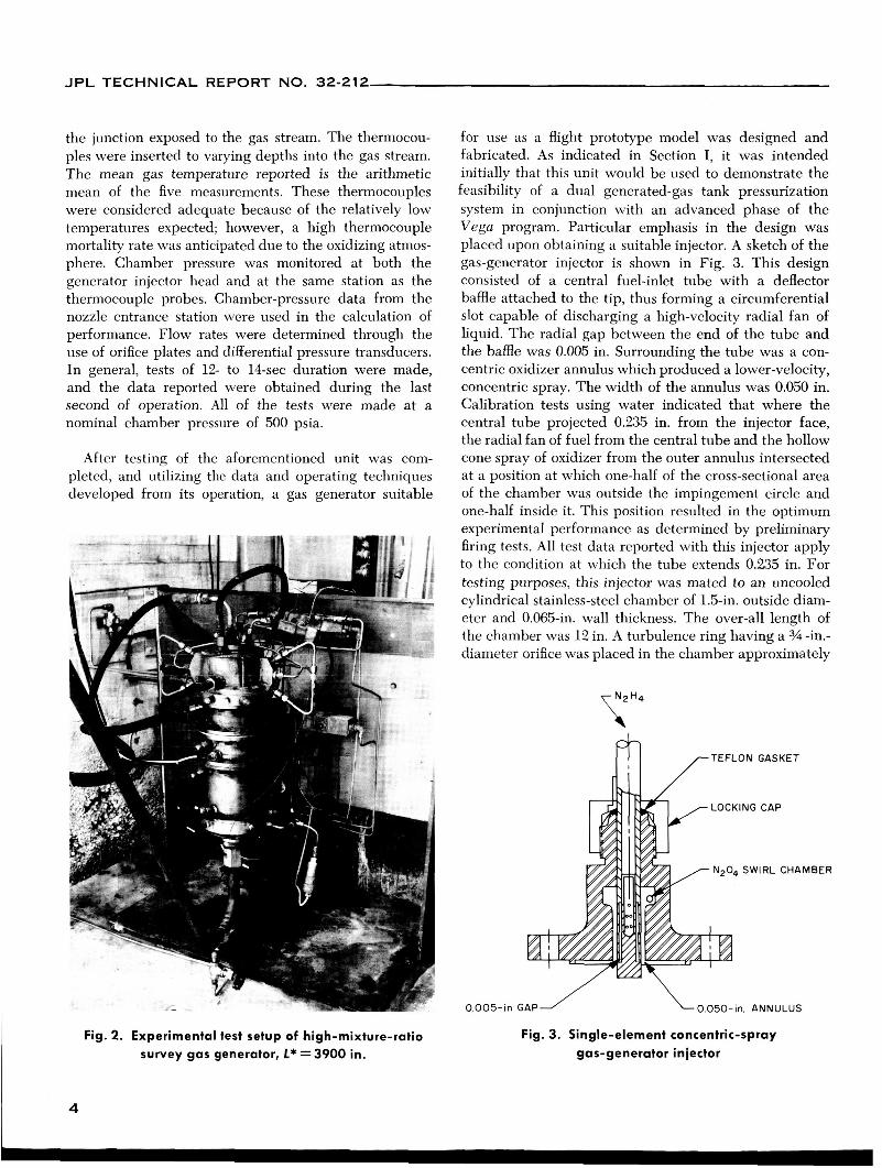
the junction exposed to the gas stream. The thermocou- ples were inserted to varying depths into the gas stream. The mean gas temperature reported is the arithmetic mean of the five measurements. These thermocouples were considered adequate because of the relatively low temperatures expected; however, a high thermocouple mortality rate was anticipated due to the oxidizing atmos- phere. Chamber pressure was monitored at both the generator injector head and at the same station as the thermocouple probes. Chamber-pressure data from the nozzle entrance station were used in the calculation of performance. Flow rates were determined through the use of orifice plates and differential pressure transducers. In general, tests of 12- to 14-sec duration were made, and the data reported were obtained during the last second of operation. All of the tests were made at a nominal chamber pressure of 500 psia.
After testing of the aforementioned unit was com- pleted, and utilizing the data and operating techniques developed from its operation, a gas generator suitable
Fig. 2. Experimental test setup of high-mixture-ratio survey gas generator, L* = 3900 in.
for use as a flight prototype model was designed and fabricated. As indicated in Section I, it was intended initially that this unit would be used to demonstrate the feasibility of a dual generated-gas tank pressurization system in conjunction with an advanced phase of the Vega program. Particular emphasis in the design was placed upon obtaining a suitable injector. A sketch of the gas-generator injector is shown in Fig. 3. This design consisted of a central fuel-inlet tube with a deflector baffle attached to the tip, thus forming a circumferential slot capable of discharging a high-velocity radial fan of liquid. The radial gap between the end of the tube and the baffle was 0.005 in. Surrounding the tube was a con- centric oxidizer annulus which produced a lower-velocity, concentric spray. The width of the annulus was 0.050 in. Calibration tests using water indicated that where the central tube projected 0.235 in. from the injector face, the radial fan of fuel from the central tube and the hollow cone spray of oxidizer from the outer annulus intersected at a position at which one-half of the cross-sectional area of the chamber was outside the impingement circle and one-half inside it. This position resulted in the optimum experimental performance as determined by preliminary firing tests. All test data reported with this injector apply to the condition at which the tube extends 0.235 in. For testing purposes, this injector was mated to an uncooled cylindrical stainless-steel chamber of 1.5-in. outside diam- eter and 0.065-in. wall thickness. The over-all length of the chamber was 12 in. A turbulence ring having a 34 -in.- diameter orifice was placed in the chamber approximately
fi /-TEFLON GASKET
0.005- in GAP L00.050-in. ANNULUS
Fig. 3. Single-element concentric-spray gas-generator injector
4

~~~~ ~~ ~~
JPL TECHNICAL REPORT NO. 32-212
675 1033 1667 466 497 563 632 71 0 778 888
1053 1261 1499
&-in. below the injector face to obtain a near-uniform temperature profile. The over-all L" of the unit was 100 in., with 62 in. of this total below the turbulence ring.
634 1038 1634 502 535 610 692 776 847 960
1128 1325 1565
The test setup of this gas generator is shown in Fig. 4. Instrumentation on the co'mbustor included three com- mercially obtained sheathed thermocouples and probes with exposed junctions. The thermocouples were located 1% in. from the aft end of the generator and were in- serted to different depths into the gas stream. The mean temperature reported is the arithmetic mean of the three measurements obtained. Two chamber-pressure trans- ducers were utilized, one near the head of the generator and one near the aft end at the same station as the ther- mocouples. Chamber-pressure measurements reported are those obtained from the transducers mounted at the aft end of the chamber. Orifice plates and differential- pressure transducers were utilized for liquid-flow meas- urements. Tests were run at chamber pressures of 400 and 500 psia. Test durations of 5, 10, and 15 sec were used in this series, with data being reduced from opera- tion during the last second of operation.
2. Results
,4 total of 21 tests were made with the two oxidizer-rich bipropellant gas generators in which data satisfactory for reduction and presentation were obtained. Utilizing the initially described combustor of 3900-in. characteristic chamber length, a series of 13 tests were made over a mixture-ratio range of 5.9 to 13.0. The data from these tests are shown in Table 1. Data from the eight tests
Table 1. High-mixture-ratio bipropellant N204-N2H4 test data, l* ~ 3 9 0 0 in.'
Test No.
322 323 324 325 326 327 328 329 330 331 332 333 334
W t
lblsec
0.73 0.59 0.47 0.70 0.68 0.66 0.64 0.60 0.58 0.54 0.50 0.46 0.42
Fig. 4. Experimental test setup of high-mixture-ratio gas generator, l* = 100 in.
using the unit of 100-in. characteristic length, covering a mixture-ratio range of 7.49 to 10.16, are reported in Table 2.
11.48 7.94 5.93
12.90 12.97 12.28 1 1.34 10.19 9.59 8.59 7.59 6.69 5.91
P C
psia
565 563 561 505 496 498 502 503 498 495 498 500 495
C*
f t fsec
1950 2410 3030 1810 1822 1895 1982 2113 2170 2310 2515 2755 2968
r, O F
620 1071 1673 527 563 628 71 6 802 877 989
1171 1372 1609
r2 O F
700 1079 1728 524 559 624 710 79 1 863 981
1158 __ -
r3 O F
578 1011 1543 493 528 606 692 782 856 964
1120 1321 1560
r4 O F
597 998
1553 502 528 628 710 795 863 977
1137 1346 1591
r5 r,,,, I O F
O F
Test duration
see
12 12 12 13 13 13 13 13 13 12 14 13 12
.Nozzle-throat area for all tests = 0.078 in.'
5

JPL TECHNICAL REPORT NO. 32-212
- 1185 799 78 1 795 813 833 833
Table 2. High-mixture-ratio bipropellant N204-N2H4 test data, L* = 100 in.'
5 5 5
15 15 10 10 10
I
1381 042 820 842 859 871 877
TI TZ
O F 1 O F
1036 70 1 697 70 1 735 744 752
- I -
I .Nozzls-throot are0 for all tests = 0.166 in . l
1137 054 825 842 863 084 871
I
In order to observe the relationship of the experimental data to the data predicted on the basis of thermodynamic equilibrium, a series of thermochemical performance cal- culations of the nitrogen tetroxide-hydrazine system were performed. These calculations were made using an IBM 7090 computer program developed by and obtained from the Aeronutronic Division of the Ford Motor Company; the program consists of an extension of the Rand method for determining equilibrium compositions by free-energy minimization. This method is described by B. R. Kubert and S. E. Stephanou in Ref. 14. Cases were run over the mixture-ratio range of 5.0 through 15.0, for chamber pressures of 300 and 500 psia exhausting to 14.7 psia. The reaction-chamber temperatures obtained from these calculations were significantly higher than the experi- mentally observed chamber temperatures through the entire mixture-ratio range investigated, apparently indi- cating, as anticipated, a non-equilibrium condition. In addition, while the program indicated essentially only H,O, N,, and 0, in the exhaust gas, with only trace quantities of NO or NO,, in fact, the observed exhaust products from the gas-generator tests were virtually opaque and varied in color from brownish-red through brown, characteristic of the nitrogen oxides. Figure 5 in- dicates the magnitude of the difference existing between the theoretical equilibrium temperatures and the ob- served chamber temperatures. Since the dissociation of both nitrogen dioxide and nitric oxide is exothermic, it is evident that the lack of decomposition of the oxides would produce gas temperatures below those predicted for equilibrium conditions. It should be noted that the test data points for both the Lo = 3900-in. and Lo = 100-in. gas generators fall essentially along a com- mon line, which would appear to indicate that even with gross excursion in residence time the approach to equi- librium conditions is not enhanced. The variation of
characteristic exhaust velocity cu with mixture ratio for both series of tests and its relation to the theoretical maximum value are presented in Fig. 6.
6. Fuel-Rich Region (Low Mixture Ratiol 1. Experimental Effort
The combustion device used in these tests was assem- bled from an existing uncooled heavy-walled gas gener- ator originally designed and used in the monopropellant circuit of the Corporal advanced-development gas-
4000
3600
DATA
0 Lf = 3900in.
0 L a = looin.
MIXTURE RATIO io /k f
Fig. 5. Variation of gas temperature with mixture ratio for the N204-N2H4 bipropellant system in the
high-mixture-ratio region
6

~ 1
JPL TECHNICAL REPORT NO. 32-212
MIXTURE RATIO wo/wf
Fig. 6. Variation of characteristic exhaust velocity c* with mixture ratio for the N20pN2H4 bipropellant system
in the high-mixture-ratio region
generation-system program mentioned in A-1. The injector, shown in Fig. 7, consisted of a 90-deg conical head having a single oxidizer-spray nozzle mounted axially at the apex of the cone and four fuel-spray nozzles mounted on the cone wall. Conventional oil-burner atomizing nozzles were used." The comblustion chamber was fab- ricated from stainless steel with an inside diameter of 3.5 in. and a wall thickness of 0.5 in. The nozzle-throat area was sized to give a chamber Lo of 250 in. The results of previous work done at the Jet Propulsion Laboratory had shown this L" value to be a lower limit at which stable thermal decomposition of monopropellant hydra- zine could he sustained reliably (Refs. 15 and 16). The experimental rocket-motor test setup is shown in Fig, 8.
Considerable effort was expended to obtain reliable combustion gas temperature data in the range of 2000 to 3000 O F ; to this end, a water-cooled, shielded, aspirating- thermocouple probe was designed and fabricated. The design objectives for the thermocouple probe were ( 1 ) to surround the measuring junction with a radiation shield, and ( 2 ) to decrease the flow velocity past the junction. The probe consisted of an 0.062-in.-diameter, piatinum- sheathed thermocouple tube, with 0.010-in.-diameter platinum and 90% platinum-10% rhodium wires em- bedded in swaged magnesium-oxide insulation. The thermocouple tube was concentrically covered by an 0.125-in.4ameter X 0.010-in. wall-thickness tantalum aspirating tube. This tube also acted as a radiation shield.
"Slanrifactiired by the Delavan SIfg. Co., West Des hloines, Iowa.
The two tubes were held concentric by a sleeve spacer, which was silver-soldered in place. To prevent the silver solder from melting at the high temperatures, a water- cooling jacket fabricated from 3's -in. tubing was soldered over the probe end. Although tantalum has very poor oxidation resistance, satisfactory operation was obtained in the highly reducing atmosphere of the low-mixture- ratio tests. A sketch of the thermocouple probe is shown in Fig. 9.
Two series of tests were conducted over the mixture- ratio range of 0.0 to 0.55. Typically, the tests were per- formed at a nominal chamber pressure of 300 +-E psia, and were of 6-sec duration. The first series of tests was made without thermocouples, the second with the ther- mocouple probes described in the preceding paragraph. Five such probes were mounted at 72-deg increments in the aft portion of the combustion chamber immediately upstream of the converging section of the nozzle. Each point in the reduced data represents an arithmetic mean of the five thermocouple measurements made at various depths in a cross-sectional plane of the test motor. Two probes were mounted approximately on the motor center- line, two at a depth of 0.9 in. (one-quarter of the motor diameter ), and one at a depth of '/2 in. The greatest single
Fig. 7. Injector used in low-mixture-ratio survey test program
7

JPL TECHNICAL REPORT NO. 32-212
Fig. 8. Experimental test setup of low-mixture-ratio survey combustor
source of error introduced in obtaining a good average temperature was found to be the nonuniform mixing of the combustion gases. The injector design caused hot spots or hot streaks through the chamber. This streaking became more noticeable as the mixture ratio was in- creased (more flow was introduced through the single oxidizer spray jet ) . Since the thermocouples are point-
WATER-COOLING JACKET
THERMOCOUPLE
JUNCTION
LAASPIRATING TUBE AND RADIATION SHIELD
Fig. 9. Water-cooled, shielded, aspirating thermocouple probe
source probes, the temperature measured is particularly dependent on the thermocouple location in relation to the injector hot streaks. Thus, it is assumed that, by taking an arithmetic mean of the five probes, a reason- ably accurate value of the average gas temperature was obtained.
Chamber pressure was recorded from an instrumenta- tion port located on the chamber side wall. Propellant- flow measurements were accomplished through the use of orifice plates and differential-pressure transducers.
2. Results
A total of 60 tests were made with the fuel-rich gas generator. As indicated, two series of tests were con- ducted; the first was accomplished with a minimum of instrumentation to determine the suitability of the test equipment and the second with the already described thermocouple probes. Data from all of the tests are re- ported in Table 3. As a result of previous investigations at JPL concerning the monopropellant characteristics of hydrazine, it was recognized that the presence of am-
8

~~~
I I
~
JPL TECHNICAL REPORT NO. 32-212 I
monia in the fuel-rich exhaust products would, at least in the very low-mixture-ratio range, lead to non-equilib- rium conditions. As was done in the case of the oxidizer- rich regime, thermochemical performance calculations were carried out in order to ascertain where such calcu-
lations might be valid for prediction of combustor opera- tion and where their use would lead to error. For ready comparison, a plot of the combustion temperature as theoretically predicted and the actual data obtained are shown in Fig. 10.
Table 3. low-mixture-ratio bipropellant N 2 0 , - N 2 H 4 test data, L* = 250 in.
Test No.
410
41 1
412
41 3
414
416
422
423
424
425
426
427
A B C D E A B C D E F G H I K B C D E A B C D E A B C D E B C D E A A B B C C A B C A B C D E F A B A B C D A B C D E F
W,
lblrec
0.55 0.56 0.56 0.56 0.57 0.58 0.58 0.58 0.57 0.57 0.57 0.57 0.56 0.56 0.56 0.51 0.51 0.51 0.51 0.50 0.51 0.49 0.49 0.50 0.47 0.48 0.49 0.49 0.48 0.47 0.47 0.49 0.48 0.56 0.55 0.57 0.56 0.58 0.57 0.54 0.55 0.55 0.52 0.53 0.53 0.51 0.51 0.52 0.51 0.52 0.53 0.52 0.49 0.50 0.52 0.50 0.51 0.51 0.49 0.50
0.040 0.043 0.050 0.053 0.052 0 0 0
0.014 0.014 0.023 0.035 0.050 0.051 0.052 0.230 0.246 0.252 0.253 0.239 0.243 0.300 0.305 0.301 0.293 0.322 0.354 0.395 0.444 0.322 0.373 0.535 0.552 0.034
0 0.033
0 0.030
0 0.041 0.039 0.044 0.085 0.098 0.109 0.145 0.154 0.154 0.214 0.212 0.209 0.234 0.275 0.267 0.316 0.284 0.301 0.303 0.365 0.362 -
P I psia
301 304 305 308 308 302 304 304 301 302 301 304 301 302 303 295 299 300 301 298 301 297 299 298 287 297 306 31 2 315 284 290 310 310 301 289 304 293 306 297 293 295 299 286 292 292 287 290 291 301 302 312 307 295 297 315 303 308 308 305 306
C *
ftlrec
4513 4478 4485 4497 4479 4307 4334 4325 4378 4376 4409 4452 4426 4475 4473 4800 4871 4879 4890 4887 4898 4986 5034 4958 5054 5047 5114 5145 5241 5037 51 24 5308 5328 4455 4350 4437 4332 4397 4318 4488 4450 4459 4577 4555 4596 4649 4683 4677 4860 4830 4805 4846 4915 4903 501 9 5000 4990 4975 5087 5068
-
-
2088 2030 2054 2027 2033 2021 2012 1988 2000 2139 2148 2151 2244 2271 2277
2435 2489 2658 2592
2051 1960 2018 1908 2000 1920 201 2 1981 1991 2166 2154 2175 2280 2349 2360 2399 2372 2372 2328 2337 2295
2082 2015 205 1 2015 2030 2009 2024 2000 1994 2139 2142 2148 2205 2250 2250 2417 2432 2444 2477 2673 2610
T. O F
2027 1846 I988 I 8 2 1 1975 1815 2030 2021 2021 2091 2139 2118 2193 2193 2259 2357 2393 3250 3140 31 10 3240
h O F
1899 1874 1852 1720 1793 1702 2277 2148 2157 2024 2091 2054 2112 2112 2109
2148 2241 2190 2202 2235
Tm... OF
-
2029 1945 1993 1898 1966 1893 2071 2026 2033 2112 2135 2129 2207 2235 2251 2391 2336 2548 2525 2596 2595
-
TSrl dumtion
sec
6 6 6 6 6 6 6 6 7 6 6 6 6 6 6 7 7 7 7 7 7 7 7 7 7 7 7 7 7 6 6 6 6
16 16 16 16 16 16 5 5 5 5 5 5 5 5 5 5 5 5 5 5 5 5 5 5 5 5 5 -
Both bipropellant and monopropellant data obtained; 6-sac bipropellant opemlion IO-sec rnonopropellonl operation
Bipropellant data only
Thermocouple data not valid; tantalum shield eroded
9

JPL TECHNICAL REPORT NO. 32-212
0
3 L
e *- lL
LQ
MIXTURE RATIO wo/w,
Fig. 10. Variation of gas temperature with mixture ratio for the N204-N2H4 bipropellant system in the
low-mixture-ratio region f G
It is interesting to note from the plot the divergence from chemical equilibrium found at the low mixture ratios. Indeed, it would appear that chemical equilibrium is not approached until a mixture of approximately 0.3 is reached. Thus, as expected, it is quite inaccurate to use equilibrium thermochemical data below this mixture ratio in combustion devices of reasonable residence time and chamber pressure. In order to better characterize this non-equilibrium region, a comparison of a series of theoretical performance curves for arbitrary fractions of ammonia dissociation have been plotted in Fig. 11, along with the experimental data obtained in this investigation. The thermochemical performance data plotted were ob-
Fig. 11. Relationship of experimental data in the low-mixture-ratio region with
calculated data having assumed percentages of ammonia
decomposition
tained from Ref. 7 and were calculated by assuming that Of the N204 was reduced by the N2H4 t' Hzo and
mole of N,04. The remaining N,H4 was assumed to decompose in accordance with the following equation (for 0% NH, decomposition) :
From this plot (Fig. 11 ), an estimate of the actual per- centage of ammonia dissociated can be obtained. At a
with data previously obtained in thermal decomposition hydrazine gas generators (Ref. 11) in which values of 29% ammonia dissociation resulted. The experimentally obtained c' for both series of tests is shown in Fig. 12.
This reaction requires two Of N2H4 for every mixture ratio of zero, the experimental data check
N,H, + NH, + %N2 + 1hH2
1 0
JPL TECHNICAL REPORT NO. 32-212
111. CONCLUSIONS
The combustion of nitrogen tetroxidehydrazine was found to be smooth and reliable over wide mixture-ratio ranges, in particular from 0 to 0.55 and from 5 to 13.0. The design and operation of suitable combustion devices in these off-mixture-ratio regimes was a straightforward task requiring only the use of conventional rocket-engine design techniques.
The off -mixture-ratio experimental performance ob- tained with this propellant system pointed up the signifi- cance of kinetic effects in low-temperature combustion systems as well as the necessity for using caution in applying thermochemical equilibrium performance cal- culations. In the oxidizer-rich regime, experimental combustion temperatures obtained were considerably lower than predicted because of the lack of exothermic
dissociation on the part of the nitrogen oxides; in the fuel-rich region, the measured temperatures were higher than predicted because of the lack of endothermic dis- sociation of ammonia.
It would appear that over the mixture-ratio range in- vestigated in the oxidizer-rich regime, the effect of varying Lo over wide limits is of little significance in altering the resultant nature of combustion products. For design purposes, the assumption of a stable gas mixture of combustion-gas temperature and characteristic exhaust velocity versus mixture ratio as determined in this study would seem to be logical. In the fuel-rich region, the use of the experimental data developed is suggested up to a mixture ratio of approximately 0.3; above this mixture ratio, assumption of a percentage of the thermochemical equilibrium value appears to be suitable.
NOMENCLATURE
ca characteristic velocity, ft/sec
La characteristic length, in.
wo weight flow of oxidizer, lb/sec
weight flow of fuel, lb/sec
T, reaction temperature, O F
12

JPL TECHNICAL REPORT NO. 32-212
0 WITHOUT TEMPERATURE PROBES A WITH TEMPERATURE PROBES
0.2 0.3 0.4
MIXTURE RATIO Wo/%
1 1 0
Fig. 12. Variation of characteristic exhaust velocity c* with mixture ratio for the N204-N2H4 bipropellant system in the low-mixture-ratio region
1 1

JPL TECHNICAL REPORT NO. 32-212
REFERENCES
1. Delcomp, J. N., and Elliott, D. G., Development of a 6000-Pound-Thrust Propulsion System Using Storable Propellants, Publication No. 30-7, Jet Propulsion Labora- tory, Pasadena, California, July 3 1, 1959. (CONFIDENTIAL)
2. Elverum, G. W., Jr., Massier, P. F., and Lee, D. H., Research and Development of Storable Propellants Using Hydrazine as the Fuel, Publication No. 30-5, Jet Pro- pulsion Laboratory, Pasadena, California, July 17, 1959. (CONFIDENTIAL)
3. Smith, W. W., The le t Propulsion laboratory 6000-Pound-Thrust Storable Propul- sion System, Publication No. 30-8, Jet Propulsion laboratory, Pasadena, Cali- fornia, July 15, 1959. (CONFIDENTIAL)
4. Bartz, D. R., Noel, M. B., and Grant, A. F., Jr., Evaluation of Hydrazine as a Regenerative Coolant, Publication No. 1 1 1, Jet Propulsion Laboratory, Pasadena, California, October 15, 1957. (CONFIDENTIAL)
5. luno IV Final Report, Jet Propulsion Laboratory, Pasadena, California, Report No. 20-1 23, December 20, 1960. (CONFIDENTIAL)
6. Cole, 1. G., The Nitrogen Oxides As Rocket Fuel Oxidants Including the Theoreti- cal Performance of Propellant Systems Employing Nitrogen Tetroxide, Progress Report No. 9-23, Jet Propulsion Laboratory, Pasadena, California, October 1 8, 1948. (CONFIDENTIAL)
7. Elverum, G. W., and Martinez, J. S., Results of Performance Calculations for N 2 0 4 - N2H4 Bipropellant System, Memorandum No. 20-1 74, Jet Propulsion Labora- tory, Pasadena, California, July 3, 1958.
8. Wise, H., and Frech, M. F., Reaction Kinetics of Rocket Propellant Gases, 1. Rate of Decomposition of Nitric Oxide at Elevated Temperatures, Progress Report No. 9-46, Jet Propulsion Laboratory, Pasadena, California, March 27, 1950.
9. Altman, D., and Penner, S. S., Chemical Reaction and the Flow Process with Spe- cific Application to Nitric Oxide Decomposition, Progress Report No. 9-5, Jet Propulsion Laboratory, Pasadena, California, May 23, 1947.
10. Grant, Arthur F., Jr., Development of Hydrazine as a Monopropellant and Gas Generant, Report No. 9-1, Jet Propulsion Laboratory, Pasadena, California, March 1, 1950. (CONFIDENTIAL)
1 1. Grant, Arthur F., Jr., Basic Factors Involved in the Design and Operation of Cata- lytic Monopropellant-Hydrazine Reaction Chambers, Report No. 20-77, Jet Pro- pulsion Laboratory, Pasadena, California, December 3 1, 1954. (CONFIDENTIAL)
12. Densmore, J. E., Dual Generated-Gas System for Pumping Propellants, Progress Report No. 20-240, Jet Propulsion Laboratory, Pasadena, California, September 30, 1954. (CONFIDENTIAL)
13. Densmore, J. E., Bell, G. L., and Stanford, H. B., Generated-Gas System for Pump- ing Propellants, Report No. 20-93, Jet Propulsion Laboratory, Pasadena, Cali- fornia, April 3, 1957. (CONFIDENTIAL)
14. Kinetics, Equilibria and Performance of High Temperature Systems, Bahn and Zukoski, editors, Proceedings of the First Conference Western States Section, The Combustion Institute, Butterworths, Washington, D. C., 1960.
15. Combined Bimonthly Summary No. 61, 1 August 1957 to 1 October 1957, Jet Pro- pulsion Laboratory, Pasadena, California, pp. 38-39. (CONFIDENTIAL)
16. Combined Bimonthly Summary No. 62, 1 October 1957 to 1 December 1957, Jet Propulsion Laboratory, Pasadena, California, pp. 45-46. (CONFIDENTIAL)
1 3