Embed Size (px)
Citation preview
- 36 -
NIPPON STEEL & SUMITOMO METAL TECHNICAL REPORT No. 117 DECEMbER 2017
UDC 621 . 318 . 3Technical Report
Development of New Reinforcement Method and 10 T Magnetization of QMG™ Magnet
Mitsuru MORITA* Hidekazu TESHIMAShinya NARIKI
AbstractRecent progress in the application of the oxide bulk superconductor (QMG ™) has been
reported. QMG is the high-Tc bulk superconductor originally developed by Nippon Steel & Sumitomo Metal Corporation. Regarding the ring-shaped QMG bulk magnet, we describe the generation of a 10 T class high magnetic field that was made possible by developing new rein-forcement technology. QMG consisting of a RE (rare earth element) -based oxide supercon-ducting material as the main component now enables the production of large high-perfor-mance materials by single crystallization techniques using the RE substitution effect. As a result, although it had potentially high superconducting properties of a bulk magnet function-ing as a 10 T class powerful magnet, the material may become cracked due to the electromag-netic force generated when magnetized. By developing a new reinforcing method, we suc-ceeded in preventing this cracking and generated a high magnetic field of more than 10 T.
1. PrefaceAbout 80% of the superconductivity technology market is con-
stituted by magnetic resonance imaging (MRI) and nuclear magnetic resonance (NMR) spectroscopy, and it is a strong magnetic field ap-plication that reaches several tesla by the superconducting magnets used in these devices. 1) After succeeding in liquefying helium in 1908, Heike Kamerlingh Onnes observed superconductivity for the first time at 4.2 K in his research using mercury and the ultralow temperature liquid helium as a refrigerant in 1911. As many re-searchers do today, he is said to have been working on the use of su-perconducting materials for the production of wire and the applica-tion to magnets, as part of the application of the superconductivity phenomenon involving the complete disappearance of materials' electrical resistance. 2) At present, MRI and NMR spectroscopy both using superconducting magnets are essential for diagnosis systems used in the medical field and analyzing systems in the drug discov-ery, analysis, and other fields, respectively. In this sense, supercon-ducting magnets are everywhere now, having penetrated society. Since the first observation of superconductivity, along with the in-crease in practical application of the phenomenon, the tenacious search for superconductors that exhibit superconductivity at higher temperatures has made progress. Following the discovery of an ox-
ide superconductor by Bednorz and Müller in 1986, high-tempera-ture superconducting substances that exhibit superconductivity at the boiling point of liquid nitrogen (77 K) were found one after an-other over the next couple of years. 3–5)
With such development, Nippon Steel & Sumitomo Metal Cor-poration started the R&D of oxide superconducting materials. We promoted the R&D with our focus on not only the search for materi-als with higher critical temperatures (critical temperature: tempera-ture at which materials exhibit the state of superconductivity [Tc]) than those of already discovered types, but also on properties in-volved in critical current density (Jc: maximum current value that can flow while the state of superconductivity is maintained), which is one of the most important parameters for the application of a su-perconducting material. This effort succeeded in producing a single crystal superconducting material, named QMG ™, excellent in the Jc property. 6, 7) This material, with a critical temperature of approx. 90 K, is a compound oxide consisting of yttrium (Y) and other rare earth elements (REs), barium (Ba), and copper (Cu). Its main com-ponent is a superconducting substance expressed as REBa2Cu3O7–x.
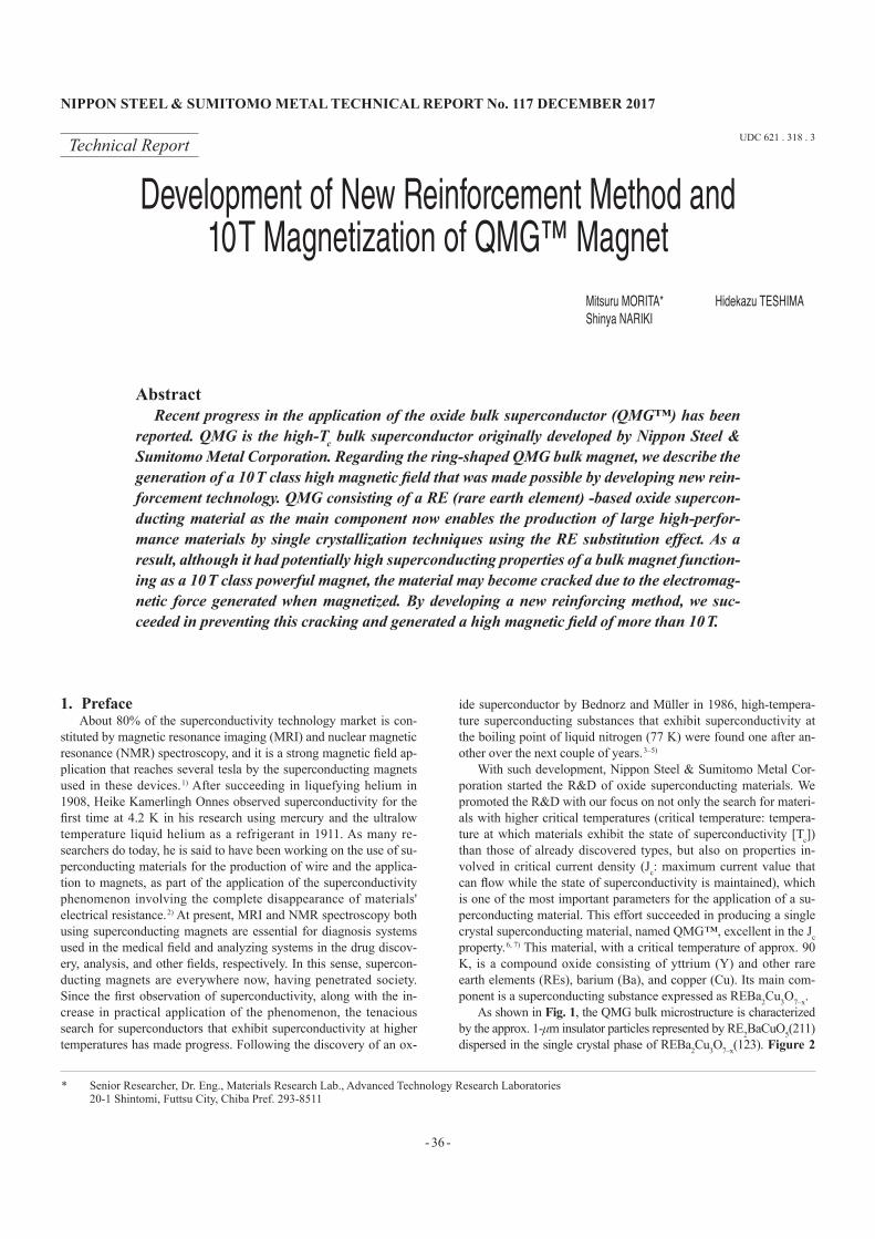
As shown in Fig. 1, the QMG bulk microstructure is characterized by the approx. 1-μm insulator particles represented by RE2BaCuO5(211) dispersed in the single crystal phase of REBa2Cu3O7–x(123). Figure 2
* Senior Researcher, Dr. Eng., Materials Research Lab., Advanced Technology Research Laboratories 20-1 Shintomi, Futtsu City, Chiba Pref. 293-8511
NIPPON STEEL & SUMITOMO METAL TECHNICAL REPORT No. 117 DECEMbER 2017
- 37 -
shows the appearance of a QMG bulk as a monocrystalline solid in which the 123 phase is grown from a seed crystal. On the surface of a QMG bulk when it has just fully grown, crystal habit lines with four-fold rotational symmetry extending from the seed crystal can be observed; this is a trace of the growth generally progressed under the condition that the seed crystal is put in contact with axis c such that the seed crystal's normal line and axis c are in the same direc-tion.
As described above, the QMG bulk has both macrostructural and microstructural characteristics: a monocrystalline material without grain boundaries, which prevent the flow of the superconducting current, constituting the material and dispersed fine 211 particles re-sponsible for the magnetic flux pinning function, respectively. The product name of “QMG” derives from the Quench and Melt Growth method, which was used when the first microstructure was pro-duced. 7, 8) After the first production, an improved Quench and Melt Growth method involving the composition substitution for REs and the use of seed crystals with a higher decomposition temperature enabled the production of a monocrystalline material, thus establish-ing the basic production method. 9–11)
With the excellent Jc property as indicated by the material struc-ture characteristics described above, R&D to expand the application of QMG is currently underway. In addition to the current lead 12) that has already been put into practical use and the magnetic bearing member 13) for power storage flywheels that is now at the verification testing stage, the use of QMG to produce bulk magnets 14) is making progress; the method involves passing permanent currents in a QMG bulk to trap magnetic fluxes in it, thereby forcing the QMG bulk to function as a permanent magnet.
During the earliest days of the bulk magnet application develop-ment, the low temperature environment had been created using liq-
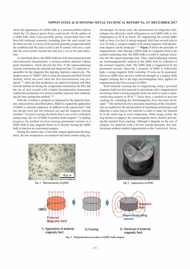
uid nitrogen. In recent years, the advancement of refrigerator tech-nologies has allowed a small refrigerator to cool QMG bulk to low temperatures at 50 K or below. By magnetizing the cooled QMG bulk to force it to have a strong magnetic field from several tesla to over 10 tesla, a compact magnet with strong magnetic field (perma-nent magnet) can be produced. 15–17) Figure 3 shows the principle of magnetization. After placing a QMG bulk in a magnetic field in the normal conducting state, the QMG bulk is cooled to undergo transi-tion into the superconducting state. Then, superconducting currents are electromagnetically induced in the QMG bulk by reduction of the external magnetic field. The QMG bulk is magnetized by the permanent currents. Since the Jc property of QMG is sufficiently high, a strong magnetic field exceeding 10 tesla can be generated. However, QMG does not have sufficient strength as a magnet. Bulk magnet cracking due to the large electromagnetic force applied for magnetization has been an issue of QMG.
Such material cracking due to magnetizing using a powerful magnetic field was first reported in association with a magnetization test during which a strong magnetic field was used to create a super-conducting magnet at 40 K. 18) Since then, a method to prevent cracking by containing the electromagnetic force has been devel-oped. 19) The method involves precision machining of the circumfer-ence as enabled by the advancement of machining technologies and adhering a metal ring to the material in order to make the material fit in the metal ring at room temperature. When being cooled, the ring shrinks to suppress the electromagnetic force, thereby prevent-ing the material from cracking. Although it depends on the size of samples, for materials with a 60-mm outside diameter, this rein-forcement method enabled magnetization at the 5 tesla level. Never-
Fig. 1 Microstructure of QMG Fig. 2 Appearance of QMG
Fig. 3 Magnetization procedure of QMG bulk magnet
- 38 -
NIPPON STEEL & SUMITOMO METAL TECHNICAL REPORT No. 117 DECEMbER 2017
theless, the application to desktop NMR spectrometers 20) and mag-netic drug delivery systems (MDDSs) 21) using ring-shaped QMG bulks in particular is in progress, increasing the required magnetic field strength. This means that a new reinforcement technology has become necessary. Meanwhile, there have been few reports on the mechanism responsible for material cracking, and the strain behav-ior of materials that cause fracturing is not well known. 22)
This paper describes the progress in the reinforcement technolo-gy development to prevent an approx. 60 mm outside diameter QMG ring from fracturing. The application expansion R&D of QMG rings in such size is being accelerated. First, the results of an examination on the trapped magnetic flux density and strain behav-ior in the magnetization process are described. Then, after an expla-nation of the concept used for the reinforcement method conceived from the findings is given, the results of test production and evalua-tion are described.
2. body2.1 Trapped magnetic flux density and strain behavior in the
magnetization process 23, 24)
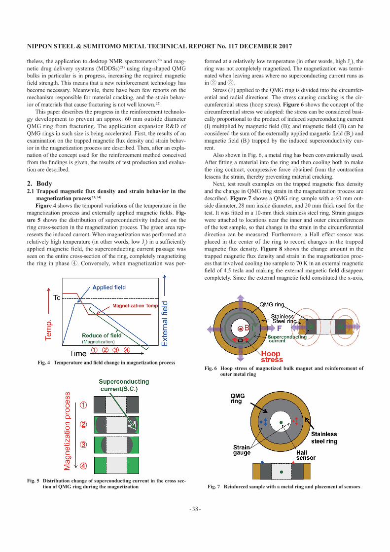
Figure 4 shows the temporal variations of the temperature in the magnetization process and externally applied magnetic fields. Fig-ure 5 shows the distribution of superconductivity induced on the ring cross-section in the magnetization process. The green area rep-resents the induced current. When magnetization was performed at a relatively high temperature (in other words, low Jc) in a sufficiently applied magnetic field, the superconducting current passage was seen on the entire cross-section of the ring, completely magnetizing the ring in phase ④. Conversely, when magnetization was per-
formed at a relatively low temperature (in other words, high Jc), the ring was not completely magnetized. The magnetization was termi-nated when leaving areas where no superconducting current runs as in ② and ③.
Stress (F) applied to the QMG ring is divided into the circumfer-ential and radial directions. The stress causing cracking is the cir-cumferential stress (hoop stress). Figure 6 shows the concept of the circumferential stress we adopted: the stress can be considered basi-cally proportional to the product of induced superconducting current (I) multiplied by magnetic field (B); and magnetic field (B) can be considered the sum of the externally applied magnetic field (Be) and magnetic field (Bt) trapped by the induced superconductivity cur-rent.
Also shown in Fig. 6, a metal ring has been conventionally used. After fitting a material into the ring and then cooling both to make the ring contract, compressive force obtained from the contraction lessens the strain, thereby preventing material cracking.
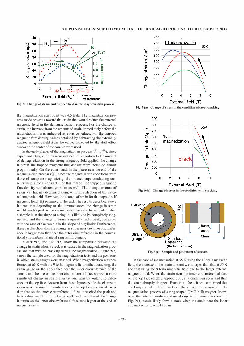
Next, test result examples on the trapped magnetic flux density and the change in QMG ring strain in the magnetization process are described. Figure 7 shows a QMG ring sample with a 60 mm out-side diameter, 28 mm inside diameter, and 20 mm thick used for the test. It was fitted in a 10-mm thick stainless steel ring. Strain gauges were attached to locations near the inner and outer circumferences of the test sample, so that change in the strain in the circumferential direction can be measured. Furthermore, a Hall effect sensor was placed in the center of the ring to record changes in the trapped magnetic flux density. Figure 8 shows the change amount in the trapped magnetic flux density and strain in the magnetization proc-ess that involved cooling the sample to 70 K in an external magnetic field of 4.5 tesla and making the external magnetic field disappear completely. Since the external magnetic field constituted the x-axis,
Fig. 4 Temperature and field change in magnetization process
Fig. 5 Distribution change of superconducting current in the cross sec-tion of QMG ring during the magnetization
Fig. 6 Hoop stress of magnetized bulk magnet and reinforcement of outer metal ring
Fig. 7 Reinforced sample with a metal ring and placement of sensors
NIPPON STEEL & SUMITOMO METAL TECHNICAL REPORT No. 117 DECEMbER 2017
- 39 -
the magnetization start point was 4.5 tesla. The magnetization pro-cess made progress toward the origin that would reduce the external magnetic field in the demagnetization process. For the change in strain, the increase from the amount of strain immediately before the magnetization was indicated as positive values. For the trapped magnetic flux density, values obtained by subtracting the externally applied magnetic field from the values indicated by the Hall effect sensor at the center of the sample were used.
In the early phases of the magnetization process (① to ②), since superconducting currents were induced in proportion to the amount of demagnetization in the strong magnetic field applied, the change in strain and trapped magnetic flux density were increased almost proportionally. On the other hand, in the phase near the end of the magnetization process (④), since the magnetization conditions were those of complete magnetizing, the induced superconducting cur-rents were almost constant. For this reason, the trapped magnetic flux density was almost constant as well. The change amount of strain was linearly decreased along with the reduction of the exter-nal magnetic field. However, the change of strain for the trapped self magnetic field (Bt) remained in the end. The results described above indicate that depending on the circumstances, the change in strain would reach a peak in the magnetization process. In particular, when a sample is in the shape of a ring, it is likely to be completely mag-netized, and the change in strain frequently had a peak, compared with the case of the sample in the shape of a cylinder. Furthermore, these results show that the change in strain near the inner circumfer-ence is larger than that near the outer circumference in the conven-tional circumferential metal ring reinforcement.
Figure 9 (a) and Fig. 9 (b) show the comparison between the change in strain when a crack was caused in the magnetization proc-ess and that with no cracking during the magnetization. Figure 9 (c) shows the sample used for the magnetization tests and the positions in which strain gauges were attached. When magnetization was per-formed at 60 K with the 9 tesla magnetic field without cracking, the strain gauge on the upper face near the inner circumference of the sample and the one on the inner circumferential face showed a more significant change in strain than the one near the outer circumfer-ence on the top face. As seen from these figures, while the change in strain near the inner circumference on the top face increased faster than that on the inner circumferential face, it reached the peak and took a downward turn quicker as well; and the value of the change in strain on the inner circumferential face rose higher at the end of magnetization.
In the case of magnetization at 55 K using the 10 tesla magnetic field, the increase of the strain amount was sharper than that at 55 K and that using the 9 tesla magnetic field due to the larger external magnetic field. When the strain near the inner circumferential face on the top face reached approx. 800 με, a crack was seen, and then the strain abruptly dropped. From these facts, it was confirmed that cracking started in the vicinity of the inner circumference in the magnetization process of a ring-shaped QMG bulk magnet. More-over, the outer circumferential metal ring reinforcement as shown in Fig. 9 (c) would likely form a crack when the strain near the inner circumference reached 800 με.
Fig. 8 Change of strain and trapped field in the magnetization processFig. 9 (a) Change of stress in the condition without cracking
Fig. 9 (b) Change of stress in the condition with cracking
Fig. 9 (c) Sample and placement of sensors
- 40 -
NIPPON STEEL & SUMITOMO METAL TECHNICAL REPORT No. 117 DECEMbER 2017
2.2 Concept of the new reinforcement methodThese test results indicate that the cracking mechanism is in-
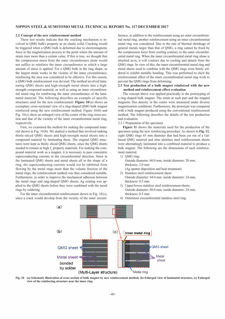
volved in QMG bulk's property as an elastic solid; Cracking would be triggered when a QMG bulk is deformed due to electromagnetic force in the magnetization process to the point where the amount of strain rises more than a certain value. If this is true, we thought that the compression stress from the outer circumference alone would not suffice to reinforce the inner circumference to which a large amount of stress is applied. For a QMG bulk in the ring shape, as the largest strain works in the vicinity of the inner circumference, reinforcing the area was considered to be effective. For this reason, a QMG bulk reinforcement was devised. The method involved lami-nating QMG sheets and high-strength metal sheets into a high-strength compound material, as well as using an inner circumferen-tial metal ring for reinforcing the inner circumference of the lami-nated material. The following describes an example of specific structures used for the new reinforcement. Figure 10 (a) shows an exemplary cross-sectional view of a ring-shaped QMG bulk magnet reinforced using the new reinforcement method. Figure 10 (b) and Fig. 10 (c) show an enlarged view of the center of the ring cross-sec-tion and that of the vicinity of the inner circumferential metal ring, respectively.
First, we examined the method for making the compound mate-rial shown in Fig. 10 (b). We studied a method that involved making thinly-sliced QMG sheets and high-strength metal sheets into a compound material by laminating these. The original QMG struc-tures were kept as thinly sliced QMG sheets, since the QMG sheets needed to remain as high Jc property materials. For making the com-pound material work as a magnet, it is necessary to pass concentric superconducting currents in the circumferential direction. Since in the laminated QMG sheets and metal sheets all in the shape of a ring, the superconducting currents would not be inhibited from flowing by the metal rings more than the volume fraction of the metal rings, the reinforcement method was thus considered suitable. Furthermore, in order to improve the mechanical adhesion between the metal rings and ring-shaped QMG sheets, Ag coating was ap-plied to the QMG sheets before they were combined with the metal rings by soldering.
For the inner circumferential reinforcement shown in Fig. 10 (c), since a crack would develop from the vicinity of the inner circum-
ference, in addition to the reinforcement using an outer circumferen-tial metal ring, another reinforcement using an inner circumferential metal ring was considered. Due to the rate of thermal shrinkage of general metals larger than that of QMG, a ring cannot be fixed by the compression force from cooling contrary to the outer circumfer-ential metal ring. When the inner circumferential metal ring alone is attached as-is, it will contract due to cooling and detach from the QMG rings. In view of this, the inner circumferential metal ring and metal sheets used to combine with the QMG rings were firmly sol-dered to exhibit metallic bonding. This was performed to elicit the reinforcement effect of the inner circumferential metal ring work to prevent the QMG rings from deforming.2.3 Test production of a bulk magnet reinforced with the new
method and reinforcement effect evaluationThe concept above was applied practically to the prototyping of
a ring-shaped bulk magnet. The strain at each part and the trapped magnetic flux density in the center were measured under diverse magnetization conditions. Furthermore, the prototype was compared with a bulk magnet produced using the conventional reinforcement method. The following describes the details of the test production and evaluation.2.3.1 Preparation of the specimen
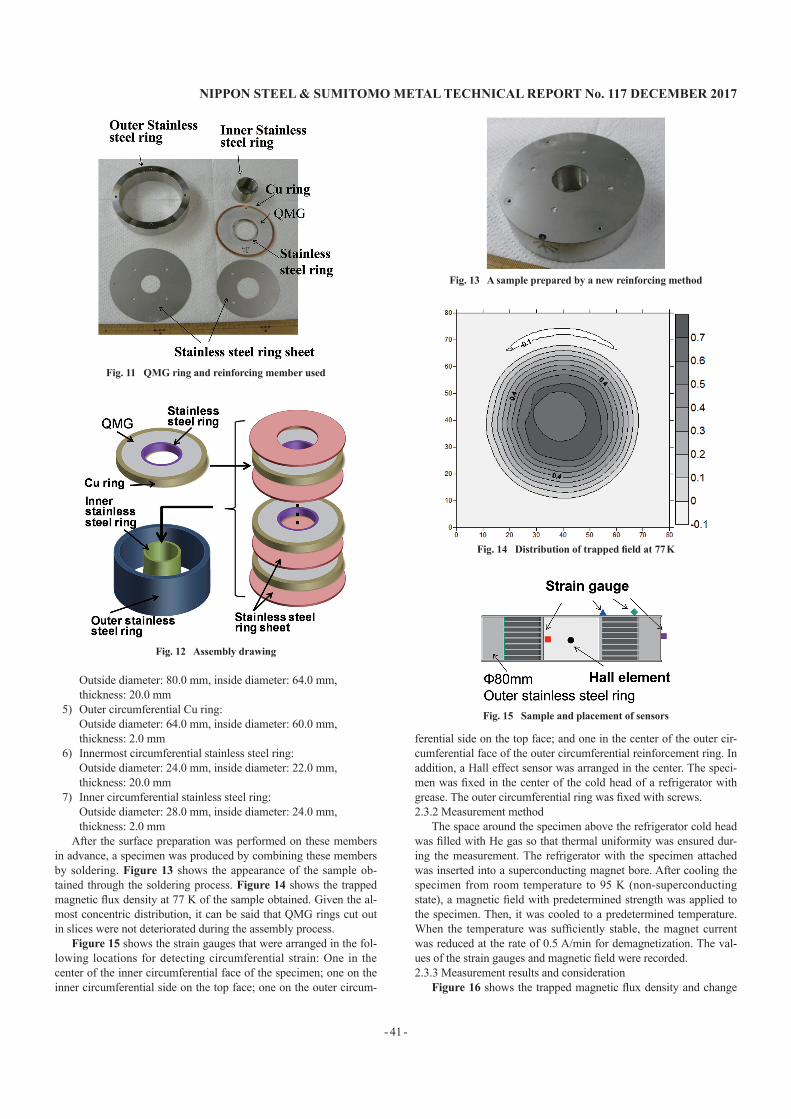
Figure 11 shows the materials used for the production of the specimen using the new reinforcing procedure. As shown in Fig. 12, eight QMG rings 65 mm diameter that had been cut out of a Gd-based QMG material and nine stainless steel reinforcement sheets were alternatingly laminated into a combined material to produce a bulk magnet. The following are the dimensions of each reinforce-ment material.
1) QMG ring: Outside diameter: 60.0 mm, inside diameter: 28 mm, thickness: 2.0 mm (Ag sputter deposition and heat treatment) 2) Stainless steel reinforcement sheet: Outside diameter: 64.0 mm, inside diameter: 24 mm, thickness: 0.5 mm3) Upper/lower stainless steel reinforcement sheets: Outside diameter: 80.0 mm, inside diameter: 24 mm, thickness: 0.5 mm4) Outermost circumferential stainless steel ring:
Fig. 10 (a) Schematic illustration of cross section of bulk magnet by new reinforcement method, (b) Enlarged view of laminated structure, (c) Enlarged view of the reinforcing structure near the inner ring
NIPPON STEEL & SUMITOMO METAL TECHNICAL REPORT No. 117 DECEMbER 2017
- 41 -
Outside diameter: 80.0 mm, inside diameter: 64.0 mm, thickness: 20.0 mm5) Outer circumferential Cu ring: Outside diameter: 64.0 mm, inside diameter: 60.0 mm, thickness: 2.0 mm6) Innermost circumferential stainless steel ring: Outside diameter: 24.0 mm, inside diameter: 22.0 mm, thickness: 20.0 mm7) Inner circumferential stainless steel ring: Outside diameter: 28.0 mm, inside diameter: 24.0 mm, thickness: 2.0 mm
After the surface preparation was performed on these members in advance, a specimen was produced by combining these members by soldering. Figure 13 shows the appearance of the sample ob-tained through the soldering process. Figure 14 shows the trapped magnetic flux density at 77 K of the sample obtained. Given the al-most concentric distribution, it can be said that QMG rings cut out in slices were not deteriorated during the assembly process.
Figure 15 shows the strain gauges that were arranged in the fol-lowing locations for detecting circumferential strain: One in the center of the inner circumferential face of the specimen; one on the inner circumferential side on the top face; one on the outer circum-
ferential side on the top face; and one in the center of the outer cir-cumferential face of the outer circumferential reinforcement ring. In addition, a Hall effect sensor was arranged in the center. The speci-men was fixed in the center of the cold head of a refrigerator with grease. The outer circumferential ring was fixed with screws.2.3.2 Measurement method
The space around the specimen above the refrigerator cold head was filled with He gas so that thermal uniformity was ensured dur-ing the measurement. The refrigerator with the specimen attached was inserted into a superconducting magnet bore. After cooling the specimen from room temperature to 95 K (non-superconducting state), a magnetic field with predetermined strength was applied to the specimen. Then, it was cooled to a predetermined temperature. When the temperature was sufficiently stable, the magnet current was reduced at the rate of 0.5 A/min for demagnetization. The val-ues of the strain gauges and magnetic field were recorded.2.3.3 Measurement results and consideration
Figure 16 shows the trapped magnetic flux density and change
Fig. 11 QMG ring and reinforcing member used
Fig. 12 Assembly drawing
Fig. 13 A sample prepared by a new reinforcing method
Fig. 14 Distribution of trapped field at 77 K
Fig. 15 Sample and placement of sensors
- 42 -
NIPPON STEEL & SUMITOMO METAL TECHNICAL REPORT No. 117 DECEMbER 2017
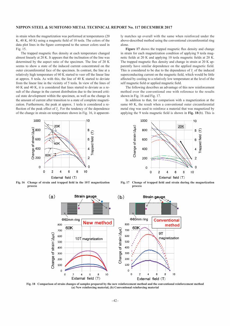
in strain when the magnetization was performed at temperatures (20 K, 40 K, 60 K) using a magnetic field of 10 tesla. The colors of the data plot lines in the figure correspond to the sensor colors used in Fig. 15.
The trapped magnetic flux density at each temperature changed almost linearly at 20 K. It appears that the inclination of the line was determined by the aspect ratio of the specimen. The line of 20 K seems to show a state of the induced current concentrated on the outer circumferential face of the specimen. In contrast, the line at a relatively high temperature of 60 K started to veer off the linear line at approx. 8 tesla. As with this, the line of 40 K started to deviate from the linear line in the vicinity of 5 tesla. In view of the lines of 60 K and 40 K, it is considered that lines started to deviate as a re-sult of the change in the current distribution due to the inward criti-cal state development within the specimen, as well as the change in the amount of current after transition to a state of complete magneti-zation. Furthermore, the peak at approx. 1 tesla is considered a re-flection of the peak effect of Jc. For the tendency of the dependence of the change in strain on temperature shown in Fig. 16, it apparent-
ly matches up overall with the same when reinforced under the above-described method using the conventional circumferential ring alone.
Figure 17 shows the trapped magnetic flux density and change in strain for each magnetization condition of applying 9 tesla mag-netic fields at 20 K and applying 10 tesla magnetic fields at 20 K. The trapped magnetic flux density and change in strain at 20 K ap-parently have similar dependence on the applied magnetic field. This is considered to be due to the dependence of Jc of the induced superconducting current on the magnetic field, which would be little affected by cooling to a relatively low temperature at the level of the self magnetic field or applied magnetic field.
The following describes an advantage of this new reinforcement method over the conventional one with reference to the results shown in Fig. 16 and Fig. 17.
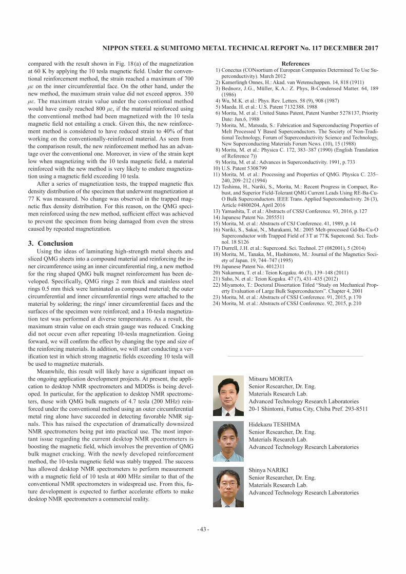
In addition to that, for comparison with a magnetization at the same 60 K, the result when a conventional outer circumferential metal ring was used to reinforce a material that was magnetized by applying the 9 tesla magnetic field is shown in Fig. 18 (b). This is
Fig. 16 Change of strain and trapped field in the 10 T magnetization process
Fig. 17 Change of trapped field and strain during the magnetization process
Fig. 18 Comparison of strain changes of samples prepared by the new reinforcement method and the conventional reinforcement method(a) New reinforcing material, (b) Conventional reinforcing material
NIPPON STEEL & SUMITOMO METAL TECHNICAL REPORT No. 117 DECEMbER 2017
- 43 -
compared with the result shown in Fig. 18 (a) of the magnetization at 60 K by applying the 10 tesla magnetic field. Under the conven-tional reinforcement method, the strain reached a maximum of 700 με on the inner circumferential face. On the other hand, under the new method, the maximum strain value did not exceed approx. 350 με. The maximum strain value under the conventional method would have easily reached 800 με, if the material reinforced using the conventional method had been magnetized with the 10 tesla magnetic field not entailing a crack. Given this, the new reinforce-ment method is considered to have reduced strain to 40% of that working on the conventionally-reinforced material. As seen from the comparison result, the new reinforcement method has an advan-tage over the conventional one. Moreover, in view of the strain kept low when magnetizing with the 10 tesla magnetic field, a material reinforced with the new method is very likely to endure magnetiza-tion using a magnetic field exceeding 10 tesla.
After a series of magnetization tests, the trapped magnetic flux density distribution of the specimen that underwent magnetization at 77 K was measured. No change was observed in the trapped mag-netic flux density distribution. For this reason, on the QMG speci-men reinforced using the new method, sufficient effect was achieved to prevent the specimen from being damaged from even the stress caused by repeated magnetization.
3. ConclusionUsing the ideas of laminating high-strength metal sheets and
sliced QMG sheets into a compound material and reinforcing the in-ner circumference using an inner circumferential ring, a new method for the ring shaped QMG bulk magnet reinforcement has been de-veloped. Specifically, QMG rings 2 mm thick and stainless steel rings 0.5 mm thick were laminated as compound material; the outer circumferential and inner circumferential rings were attached to the material by soldering; the rings' inner circumferential faces and the surfaces of the specimen were reinforced; and a 10-tesla magnetiza-tion test was performed at diverse temperatures. As a result, the maximum strain value on each strain gauge was reduced. Cracking did not occur even after repeating 10-tesla magnetization. Going forward, we will confirm the effect by changing the type and size of the reinforcing materials. In addition, we will start conducting a ver-ification test in which strong magnetic fields exceeding 10 tesla will be used to magnetize materials.
Meanwhile, this result will likely have a significant impact on the ongoing application development projects. At present, the appli-cation to desktop NMR spectrometers and MDDSs is being devel-oped. In particular, for the application to desktop NMR spectrome-ters, those with QMG bulk magnets of 4.7 tesla (200 MHz) rein-forced under the conventional method using an outer circumferential metal ring alone have succeeded in detecting favorable NMR sig-nals. This has raised the expectation of dramatically downsized NMR spectrometers being put into practical use. The most impor-tant issue regarding the current desktop NMR spectrometers is boosting the magnetic field, which involves the prevention of QMG bulk magnet cracking. With the newly developed reinforcement method, the 10-tesla magnetic field was stably trapped. The success has allowed desktop NMR spectrometers to perform measurement with a magnetic field of 10 tesla at 400 MHz similar to that of the conventional NMR spectrometers in widespread use. From this, fu-ture development is expected to further accelerate efforts to make desktop NMR spectrometers a commercial reality.
References1) Conectus (CONsortium of European Companies Determined To Use Su-
perconductivity). March 20122) Kamerlingh Onnes, H.: Akad. van Wetenschappen. 14, 818 (1911)3) Bednorz, J. G., Müller, K. A.: Z. Phys, B-Condensed Matter. 64, 189
(1986)4) Wu, M. K. et al.: Phys. Rev. Letters. 58 (9), 908 (1987)5) Maeda. H. et al.: U.S. Patent 7 132 388. 19886) Morita, M. et al.: United States Patent, Patent Number 5 278 137, Priority
Date: Jun.6, 19887) Morita, M., Matsuda, S.: Fabrication and Superconducting Properties of
Melt Processed Y Based Superconductors. The Society of Non-Tradi-tional Technology, Forum of Superconductivity Science and Technology, New Superconducting Materials Forum News. (10), 15 (1988)
8) Morita, M. et al.: Physica C. 172, 383–387 (1990) (English Translation of Reference 7))
9) Morita, M. et al.: Advances in Superconductivity. 1991, p. 73310) U.S. Patent 5 308 79911) Morita, M. et al.: Processing and Properties of QMG. Physica C. 235–
240, 209–212 (1994)12) Teshima, H., Nariki, S., Morita, M.: Recent Progress in Compact, Ro-
bust, and Superior Field-Tolerant QMG Current Leads Using RE-Ba-Cu-O Bulk Superconductors. IEEE Trans. Applied Superconductivity. 26 (3), Article #4800204, April 2016
13) Yamashita, T. et al.: Abstracts of CSSJ Conference. 93, 2016, p. 12714) Japanese Patent No. 205551115) Morita, M. et al.: Abstracts of CSJ Conference. 41, 1989, p. 1416) Nariki, S., Sakai, N., Murakami, M.: 2005 Melt-processed Gd-Ba-Cu-O
Superconductor with Trapped Field of 3 T at 77 K Supercond. Sci. Tech-nol. 18 S126
17) Durrell, J. H. et al.: Supercond. Sci. Technol. 27 (082001), 5 (2014)18) Morita, M., Tanaka, M., Hashimoto, M.: Journal of the Magnetics Soci-
ety of Japan. 19, 744–747 (1995)19) Japanese Patent No. 401231120) Nakamura, T. et al.: Teion Kogaku. 46 (3), 139–148 (2011)21) Saho, N. et al.: Teion Kogaku. 47 (7), 431–435 (2012)22) Miyamoto, T.: Doctoral Dissertation Titled “Study on Mechanical Prop-
erty Evaluation of Large Bulk Superconductors”. Chapter 4, 200123) Morita, M. et al.: Abstracts of CSSJ Conference. 91, 2015, p. 17024) Morita, M. et al.: Abstracts of CSSJ Conference. 92, 2015, p. 210
Mitsuru MORITASenior Researcher, Dr. Eng. Materials Research Lab.Advanced Technology Research Laboratories20-1 Shintomi, Futtsu City, Chiba Pref. 293-8511
Hidekazu TESHIMASenior Researcher, Dr. Eng.Materials Research Lab.Advanced Technology Research Laboratories
Shinya NARIKISenior Researcher, Dr. Eng.Materials Research Lab.Advanced Technology Research Laboratories