Embed Size (px)
Citation preview
NIPPON STEEL & SUMITOMO METAL TECHNICAL REPORT No. 117 DECEMbER 2017
- 23 -
UDC 621 . 354 . 035 . 1Technical Report
Mechanical and Forming Properties of LAMINELITE™, Laminated Stainless Steel Foil for Battery Packaging
Masaharu IBARAGI* Koichi NOSEHiroto UNNO Naoki FUJIMOTOMasahiro FUKUDA
AbstractDue to its excellent properties of easy heat sealing to seal off moisture and forming flex-
ibility, laminated aluminum foil has been widely used for the soft packs for packaging ac-cumulator batteries such as lithium ion secondary batteries and capacitors. However, prob-lems have arisen due to its low strength. It is possible to improve its strength and other mechanical properties maintaining the advantages by using stainless steel foil as the base material of the laminates. In addition, this makes it possible to better seal the package against moisture by laser-welding heat-sealed edges, which was difficult with conventional soft packs. The new package material is expected to be instrumental in improving the per-formance of batteries.
1. IntroductionFor packaging accumulator batteries such as lithium ion second-
ary batteries and capacitors, three types of containers are widely used: laminate pouches (or soft packs) and cylindrical and square cans. 1) Of these, laminate pouches, made of metal base material (foils) laminated with resin films, are suitable for packaging flat and large-size batteries due to easy heat sealing and forming work. Their market share has increased recently thanks to the expanding use of smart phones, tablet devices, and the like.
While aluminum foil is commonly used as the base material of the laminates at present, it is meant mainly as a moisture barrier, and because of its low strength and rigidity, it is prone to deformation under puncturing and other external force. Therefore, there is much room for improvement of its mechanical properties as a container material. 2)
In the meantime, it is possible to strengthen soft battery packs while maintaining their advantages by using a ferrous material, stainless steel foil, as the base material for laminate pouches. 3, 4)
Strengthening of soft packs makes it possible to simplify or elimi-nate external battery components that are presently provided to pro-tect fragile soft packs, and the weight and costs of batteries can be further reduced. On the other hand, thinner and thinner laminates are required for battery containers recently especially for mobile
electronic devices, but when they are too thin, the risk of pin holes in the base metal foil increases. In this respect, too, stainless steel is less prone to pin holes during foil rolling than aluminum. 5) There have also been many cases of fire especially of lithium ion second-ary batteries. Since aluminum melts at temperatures (660°C) far lower than that at which stainless steel does (1 500°C), it is vulnera-ble to temperature rise. Moreover, since it is an active element, it has a risk of entering into a thermite reaction leading to thermal run-away, but such a risk of dangerous chemical reaction is unlikely with stainless steel.
As stated above, the use of stainless steel foil as the base metal of the laminate for the battery soft packs has many advantages, but this requires high technology for the production of very thin foil. The Metal Foil Company of Nippon Steel & Sumikin Materials Co., Ltd. (NSMAT) is capable of this. The company manufactures and sells stainless steel foil in a self-contained manner, and is character-ized by integrated production and quality control systems, the proc-esses from materials procurement to foil rolling and forming being completed autonomously within the group of Nippon Steel & Sumi-tomo Metal Corporation. Its excellent rolling expertise ensures ac-curate thickness and flatness control in very thin gauges. Thanks to its world leading technology for ultra-thin gauge stainless steel foil, NSMAT maintains an overwhelming share in the field of the sus-
* Senior Researcher, Ph.D., Materials Research Lab., Advanced Technology Research Laboratories 20-1 Shintomi, Futtsu City, Chiba Pref. 293-8511
- 24 -
NIPPON STEEL & SUMITOMO METAL TECHNICAL REPORT No. 117 DECEMbER 2017
pension for hard disc drives in the world market. In consideration of the further down-sizing of electronic devices, especially in thick-ness, and consequent need for thinner batteries in the future, the stainless steel foil of NSMAT is the most suitable for the base mate-rial of laminate pouches.
The present paper considers the excellent mechanical and form-ing properties of laminated stainless steel foil for battery cases, mar-keted under the trade name of LAMINELITE™; more specifically, with respect to the mechanical properties, it presents the advantages in the use of stainless steel with high Young's modulus and strength for the soft packs, and with respect to the forming properties, wide freedom in shape forming, control of metallographic structure to re-alize the freedom in forming, and revolutionary welded laminate pouches that can seal out moisture to the lowest possible level.
2. Mechanical Properties2.1 Analysis of package deformation under increased internal
pressure by simulationThe Young's moduli and the tensile strengths of stainless steel
and aluminum are, respectively, as follows: Young's moduli 200 and 70 kN/mm2, approximately, and tensile strengths 800 and 200 MPa. 6) Since the figures of stainless steel are three to four times larger than those of aluminum, the use of stainless steel as the base material of the laminate is expected to add such excellent mechani-cal properties as higher strength and resistance to deformation to the soft pack, enhancing the operational stability and safety of the bat-tery elements. 4)
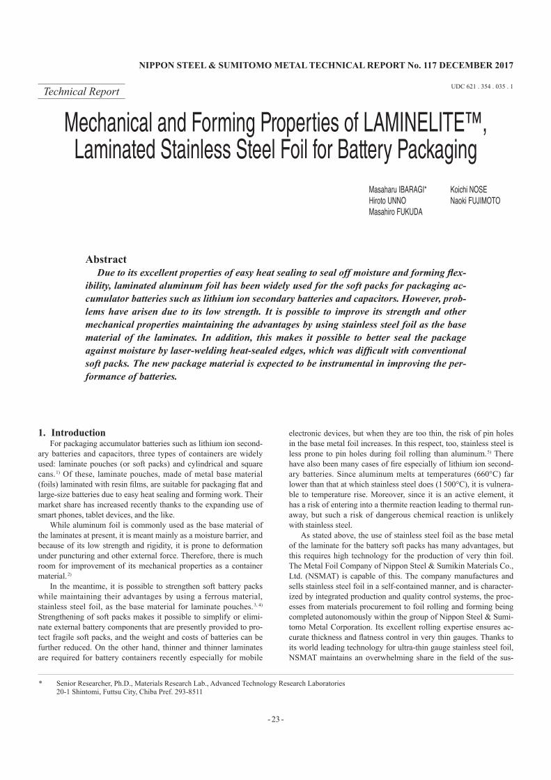
Using the FEM analysis function of the software package Marc, we calculated by simulation the bulging of battery cases made of laminated stainless steel and aluminum foils, and the distribution of the stress imposed on the heat seal resin when the pressure inside the case increased by 0.3 kg/cm2. 4) Here, the laminates were as-sumed to consist of metal foils 50 μm in thickness and resin sheets of polypropylene (PP) 60 μm in thickness, the cases to be 35 × 45 × 5 mm in size and to be heat sealed in a band 10 mm in width along the edges.
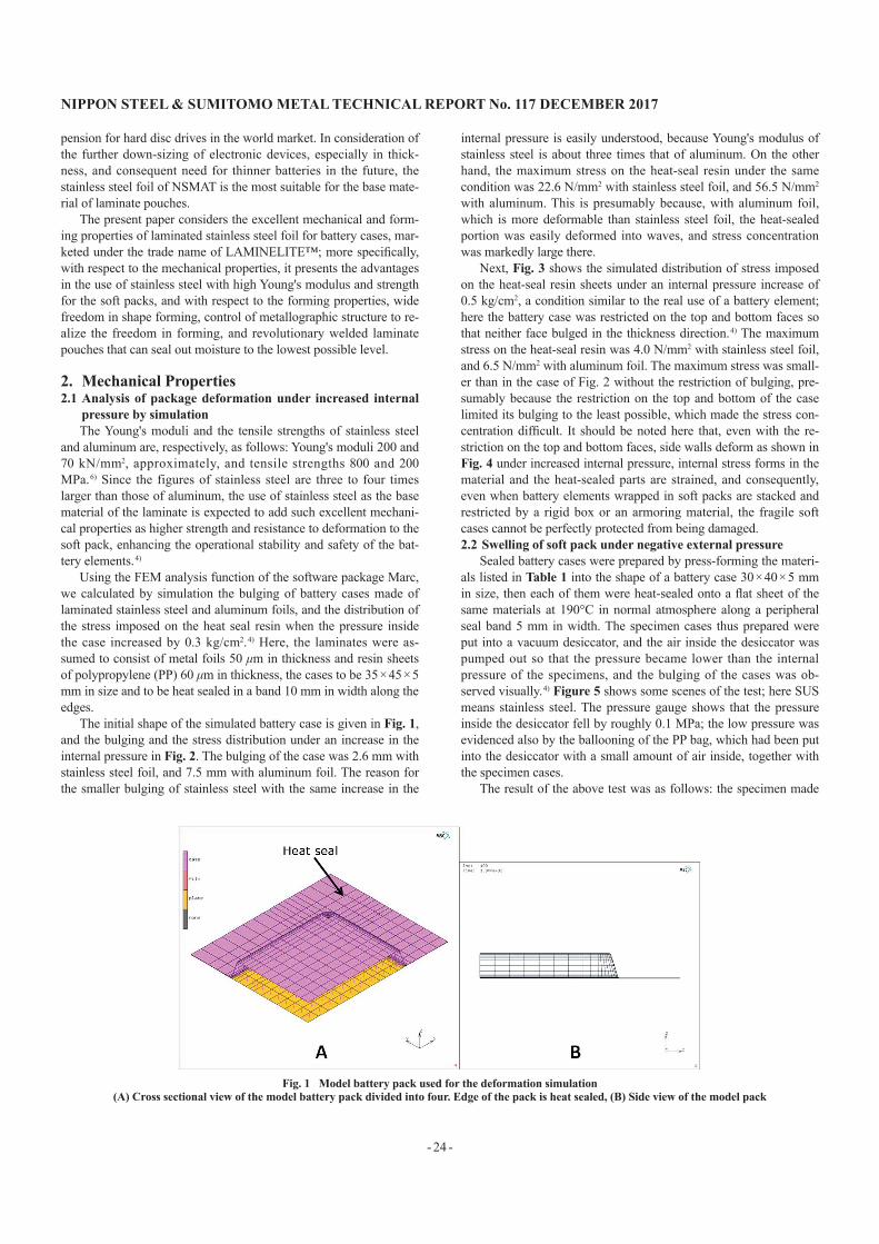
The initial shape of the simulated battery case is given in Fig. 1, and the bulging and the stress distribution under an increase in the internal pressure in Fig. 2. The bulging of the case was 2.6 mm with stainless steel foil, and 7.5 mm with aluminum foil. The reason for the smaller bulging of stainless steel with the same increase in the
internal pressure is easily understood, because Young's modulus of stainless steel is about three times that of aluminum. On the other hand, the maximum stress on the heat-seal resin under the same condition was 22.6 N/mm2 with stainless steel foil, and 56.5 N/mm2 with aluminum. This is presumably because, with aluminum foil, which is more deformable than stainless steel foil, the heat-sealed portion was easily deformed into waves, and stress concentration was markedly large there.
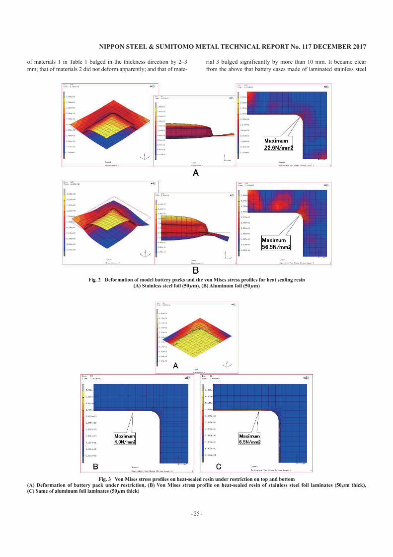
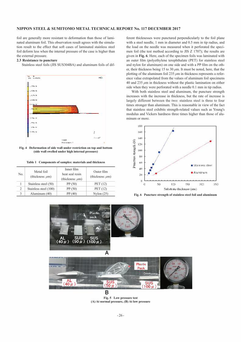
Next, Fig. 3 shows the simulated distribution of stress imposed on the heat-seal resin sheets under an internal pressure increase of 0.5 kg/cm2, a condition similar to the real use of a battery element; here the battery case was restricted on the top and bottom faces so that neither face bulged in the thickness direction. 4) The maximum stress on the heat-seal resin was 4.0 N/mm2 with stainless steel foil, and 6.5 N/mm2 with aluminum foil. The maximum stress was small-er than in the case of Fig. 2 without the restriction of bulging, pre-sumably because the restriction on the top and bottom of the case limited its bulging to the least possible, which made the stress con-centration difficult. It should be noted here that, even with the re-striction on the top and bottom faces, side walls deform as shown in Fig. 4 under increased internal pressure, internal stress forms in the material and the heat-sealed parts are strained, and consequently, even when battery elements wrapped in soft packs are stacked and restricted by a rigid box or an armoring material, the fragile soft cases cannot be perfectly protected from being damaged.2.2 Swelling of soft pack under negative external pressure
Sealed battery cases were prepared by press-forming the materi-als listed in Table 1 into the shape of a battery case 30 × 40 × 5 mm in size, then each of them were heat-sealed onto a flat sheet of the same materials at 190°C in normal atmosphere along a peripheral seal band 5 mm in width. The specimen cases thus prepared were put into a vacuum desiccator, and the air inside the desiccator was pumped out so that the pressure became lower than the internal pressure of the specimens, and the bulging of the cases was ob-served visually. 4) Figure 5 shows some scenes of the test; here SUS means stainless steel. The pressure gauge shows that the pressure inside the desiccator fell by roughly 0.1 MPa; the low pressure was evidenced also by the ballooning of the PP bag, which had been put into the desiccator with a small amount of air inside, together with the specimen cases.
The result of the above test was as follows: the specimen made
Fig. 1 Model battery pack used for the deformation simulation(A) Cross sectional view of the model battery pack divided into four. Edge of the pack is heat sealed, (b) Side view of the model pack
NIPPON STEEL & SUMITOMO METAL TECHNICAL REPORT No. 117 DECEMbER 2017
- 25 -
of materials 1 in Table 1 bulged in the thickness direction by 2–3 mm; that of materials 2 did not deform apparently; and that of mate-
rial 3 bulged significantly by more than 10 mm. It became clear from the above that battery cases made of laminated stainless steel
Fig. 2 Deformation of model battery packs and the von Mises stress profiles for heat sealing resin(A) Stainless steel foil (50 µm), (b) Aluminum foil (50 µm)
Fig. 3 Von Mises stress profiles on heat-sealed resin under restriction on top and bottom(A) Deformation of battery pack under restriction, (B) Von Mises stress profile on heat-sealed resin of stainless steel foil laminates (50 µm thick), (C) Same of aluminum foil laminates (50 µm thick)
- 26 -
NIPPON STEEL & SUMITOMO METAL TECHNICAL REPORT No. 117 DECEMbER 2017
foil are generally more resistant to deformation than those of lami-nated aluminum foil. This observation result agrees with the simula-tion result to the effect that soft cases of laminated stainless steel foil deform less when the internal pressure of the case is higher than the external pressure.2.3 Resistance to puncture
Stainless steel foils (JIS SUS304BA) and aluminum foils of dif-
ferent thicknesses were punctured perpendicularly to the foil plane with a steel needle, 1 mm in diameter and 0.5 mm in tip radius, and the load on the needle was measured when it perforated the speci-men foil (the test method according to JIS Z 1707); the results are given in Fig. 6. Here, each of the specimen foils was laminated with an outer film (polyethylene terephthalate (PET) for stainless steel and nylon for aluminum) on one side and with a PP film on the oth-er, their thickness being 15 to 30 μm. It must be noted, here, that the plotting of the aluminum foil 235 μm in thickness represents a refer-ence value extrapolated from the values of aluminum foil specimens 40 and 235 μm in thickness without the plastic lamination on either side when they were perforated with a needle 0.1 mm in tip radius.
With both stainless steel and aluminum, the puncture strength increases with the increase in thickness, but the rate of increase is largely different between the two: stainless steel is three to four times stronger than aluminum. This is reasonable in view of the fact that stainless steel exhibits strength-related values such as Young's modulus and Vickers hardness three times higher than those of alu-minum or more.
Fig. 4 Deformation of side wall under restriction on top and bottom(side wall swelled under high internal pressure)
Table 1 Components of samples: materials and thickness
No.Metal foil
(thickness: μm)
Inner film heat seal resin
(thickness: μm)
Outer film (thickness: μm)
1 Stainless steel (50) PP (50) PET (12)2 Stainless steel (100) PP (50) PET (12)3 Aluminum (40) PP (40) Nylon (25) Fig. 6 Puncture strength of stainless steel foil and aluminum
Fig. 5 Low pressure test(A) At normal pressure, (b) At low pressure
NIPPON STEEL & SUMITOMO METAL TECHNICAL REPORT No. 117 DECEMbER 2017
- 27 -
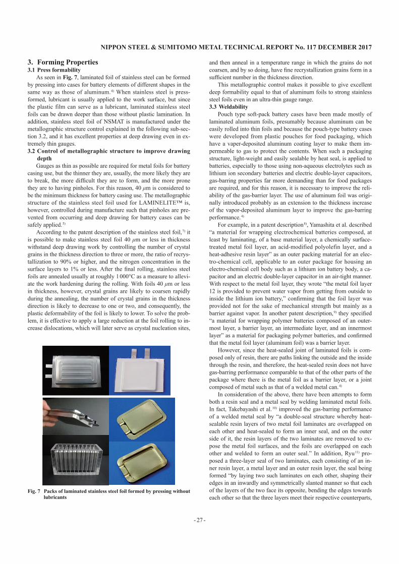
3. Forming Properties3.1 Press formability
As seen in Fig. 7, laminated foil of stainless steel can be formed by pressing into cases for battery elements of different shapes in the same way as those of aluminum. 4) When stainless steel is press-formed, lubricant is usually applied to the work surface, but since the plastic film can serve as a lubricant, laminated stainless steel foils can be drawn deeper than those without plastic lamination. In addition, stainless steel foil of NSMAT is manufactured under the metallographic structure control explained in the following sub-sec-tion 3.2, and it has excellent properties at deep drawing even in ex-tremely thin gauges.3.2 Control of metallographic structure to improve drawing
depthGauges as thin as possible are required for metal foils for battery
casing use, but the thinner they are, usually, the more likely they are to break, the more difficult they are to form, and the more prone they are to having pinholes. For this reason, 40 μm is considered to be the minimum thickness for battery casing use. The metallographic structure of the stainless steel foil used for LAMINELITE™ is, however, controlled during manufacture such that pinholes are pre-vented from occurring and deep drawing for battery cases can be safely applied. 5)
According to the patent description of the stainless steel foil, 7) it is possible to make stainless steel foil 40 μm or less in thickness withstand deep drawing work by controlling the number of crystal grains in the thickness direction to three or more, the ratio of recrys-tallization to 90% or higher, and the nitrogen concentration in the surface layers to 1% or less. After the final rolling, stainless steel foils are annealed usually at roughly 1 000°C as a measure to allevi-ate the work hardening during the rolling. With foils 40 μm or less in thickness, however, crystal grains are likely to coarsen rapidly during the annealing, the number of crystal grains in the thickness direction is likely to decrease to one or two, and consequently, the plastic deformability of the foil is likely to lower. To solve the prob-lem, it is effective to apply a large reduction at the foil rolling to in-crease dislocations, which will later serve as crystal nucleation sites,
and then anneal in a temperature range in which the grains do not coarsen, and by so doing, have fine recrystallization grains form in a sufficient number in the thickness direction.
This metallographic control makes it possible to give excellent deep formability equal to that of aluminum foils to strong stainless steel foils even in an ultra-thin gauge range.3.3 Weldability
Pouch type soft-pack battery cases have been made mostly of laminated aluminum foils, presumably because aluminum can be easily rolled into thin foils and because the pouch-type battery cases were developed from plastic pouches for food packaging, which have a vaper-deposited aluminum coating layer to make them im-permeable to gas to protect the contents. When such a packaging structure, light-weight and easily sealable by heat seal, is applied to batteries, especially to those using non-aqueous electrolytes such as lithium ion secondary batteries and electric double-layer capacitors, gas-barring properties far more demanding than for food packages are required, and for this reason, it is necessary to improve the reli-ability of the gas-barrier layer. The use of aluminum foil was origi-nally introduced probably as an extension to the thickness increase of the vapor-deposited aluminum layer to improve the gas-barring performance. 4)
For example, in a patent description 8), Yamashita et al. described “a material for wrapping electrochemical batteries composed, at least by laminating, of a base material layer, a chemically surface-treated metal foil layer, an acid-modified polyolefin layer, and a heat-adhesive resin layer” as an outer packing material for an elec-tro-chemical cell, applicable to an outer package for housing an electro-chemical cell body such as a lithium ion battery body, a ca-pacitor and an electric double-layer capacitor in an air-tight manner. With respect to the metal foil layer, they wrote “the metal foil layer 12 is provided to prevent water vapor from getting from outside to inside the lithium ion battery,” confirming that the foil layer was provided not for the sake of mechanical strength but mainly as a barrier against vapor. In another patent description, 9) they specified “a material for wrapping polymer batteries composed of an outer-most layer, a barrier layer, an intermediate layer, and an innermost layer” as a material for packaging polymer batteries, and confirmed that the metal foil layer (aluminum foil) was a barrier layer.
However, since the heat-sealed joint of laminated foils is com-posed only of resin, there are paths linking the outside and the inside through the resin, and therefore, the heat-sealed resin does not have gas-barring performance comparable to that of the other parts of the package where there is the metal foil as a barrier layer, or a joint composed of metal such as that of a welded metal can. 4)
In consideration of the above, there have been attempts to form both a resin seal and a metal seal by welding laminated metal foils. In fact, Takebayashi et al. 10) improved the gas-barring performance of a welded metal seal by “a double-seal structure whereby heat-sealable resin layers of two metal foil laminates are overlapped on each other and heat-sealed to form an inner seal, and on the outer side of it, the resin layers of the two laminates are removed to ex-pose the metal foil surfaces, and the foils are overlapped on each other and welded to form an outer seal.” In addition, Ryu 11) pro-posed a three-layer seal of two laminates, each consisting of an in-ner resin layer, a metal layer and an outer resin layer, the seal being formed “by laying two such laminates on each other, shaping their edges in an inwardly and symmetrically slanted manner so that each of the layers of the two face its opposite, bending the edges towards each other so that the three layers meet their respective counterparts,
Fig. 7 Packs of laminated stainless steel foil formed by pressing without lubricants
- 28 -
NIPPON STEEL & SUMITOMO METAL TECHNICAL REPORT No. 117 DECEMbER 2017
and joining them so that the inner layers of the two form an inner heat-sealed joint, the metal foil layers form a welded joint in the middle, and the outer layers form a heat-sealed outer joint.”
When laminated metal foils are welded together, however, the resin layers hinder direct contact of the metal foils and work as insu-lators. As a result, if resistance welding or ultrasonic welding is em-ployed, it is necessary to remove the resin layers from the portions to weld, which is an additional and troublesome process step. On the other hand, when the heat for welding is supplied from outside, such as in arc welding or laser welding, the resin is decomposed and gas is generated at temperatures far lower than the melting point of the metal. As a result, when the metal is melted, it is mostly blown away by the gas; such explosion thus occurs inevitably. For this rea-son, both Takebayashi et al. and Ryu recommend removal of the resin layers from the weld joint as a pre-treatment.
With laminates of stainless steel foil, in contrast, in consideration of the facts that the melting point of ferrous material is far higher than that of aluminum alloys, that the specific weight of stainless steel is greater, that it is more suitable for laser welding than alumi-num owing to a lower reflectance ratio and thermal conductivity, 12) etc., there may be a condition where it is possible to form a seal by metal welding without having to remove the resin layers before-hand. 4) This is because the effects of gas on molten metal are ex-pected to decrease with the increase in the difference between the melting point of the metal and the temperature of gas generation from the resin, and with the higher specific weight of the metal.
Stainless steel laminate was prepared using foil of JIS SUS-304BA of NSMAT, 100 μm in thickness, as the substrate, a PP sheet 50 μm in thickness as the inner heat-seal film, and a PET sheet 12 μm in thickness as the outer film. Edge-heat-seal specimens were prepared by cutting the laminate into 100-mm squares, putting two square sheets together with the PP side contacting each other, they were heat-sealed in a band 5 mm in width along an edge by holding at 190°C for 5 s under a pressing load of 0.5 MPa using a heat sealer having aluminum heat-seal bars, and then left to cool in the atmo-sphere.
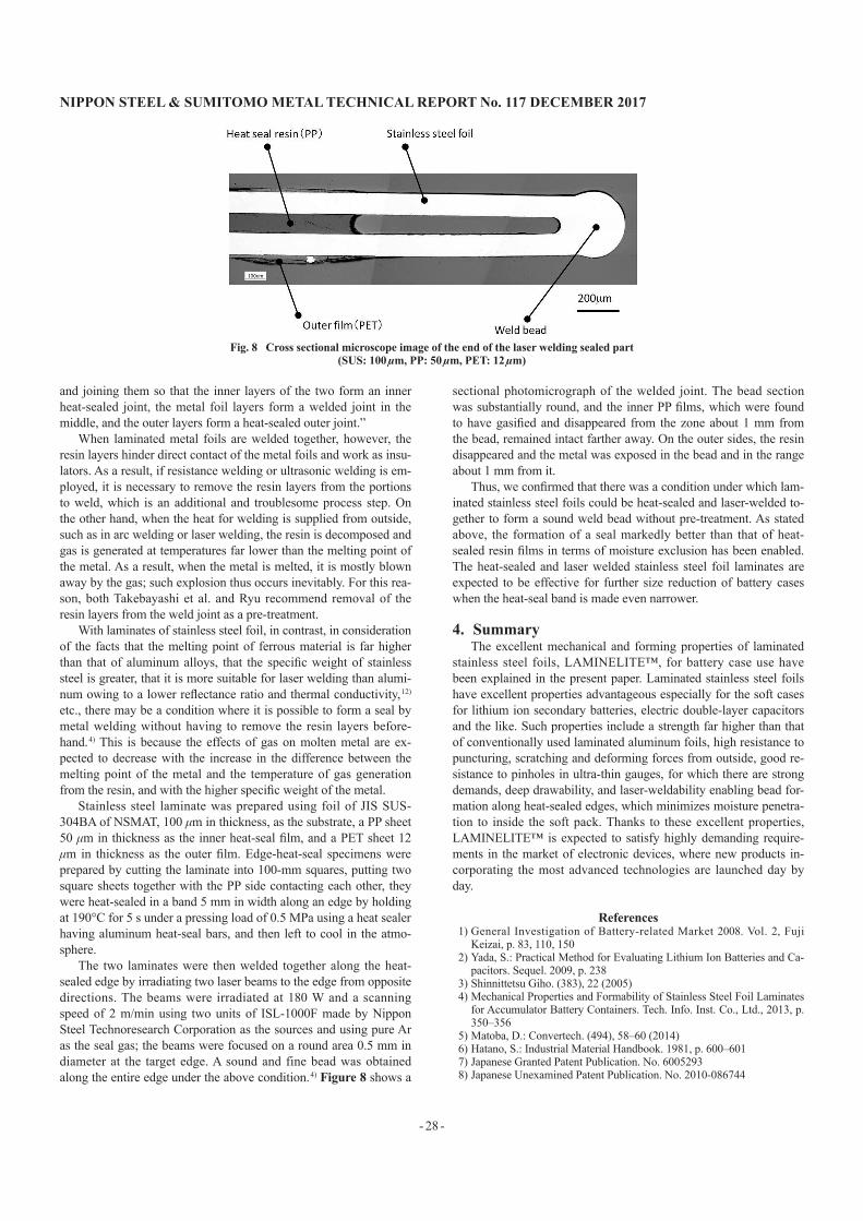
The two laminates were then welded together along the heat-sealed edge by irradiating two laser beams to the edge from opposite directions. The beams were irradiated at 180 W and a scanning speed of 2 m/min using two units of ISL-1000F made by Nippon Steel Technoresearch Corporation as the sources and using pure Ar as the seal gas; the beams were focused on a round area 0.5 mm in diameter at the target edge. A sound and fine bead was obtained along the entire edge under the above condition. 4) Figure 8 shows a
sectional photomicrograph of the welded joint. The bead section was substantially round, and the inner PP films, which were found to have gasified and disappeared from the zone about 1 mm from the bead, remained intact farther away. On the outer sides, the resin disappeared and the metal was exposed in the bead and in the range about 1 mm from it.
Thus, we confirmed that there was a condition under which lam-inated stainless steel foils could be heat-sealed and laser-welded to-gether to form a sound weld bead without pre-treatment. As stated above, the formation of a seal markedly better than that of heat-sealed resin films in terms of moisture exclusion has been enabled. The heat-sealed and laser welded stainless steel foil laminates are expected to be effective for further size reduction of battery cases when the heat-seal band is made even narrower.
4. SummaryThe excellent mechanical and forming properties of laminated
stainless steel foils, LAMINELITE™, for battery case use have been explained in the present paper. Laminated stainless steel foils have excellent properties advantageous especially for the soft cases for lithium ion secondary batteries, electric double-layer capacitors and the like. Such properties include a strength far higher than that of conventionally used laminated aluminum foils, high resistance to puncturing, scratching and deforming forces from outside, good re-sistance to pinholes in ultra-thin gauges, for which there are strong demands, deep drawability, and laser-weldability enabling bead for-mation along heat-sealed edges, which minimizes moisture penetra-tion to inside the soft pack. Thanks to these excellent properties, LAMINELITE™ is expected to satisfy highly demanding require-ments in the market of electronic devices, where new products in-corporating the most advanced technologies are launched day by day.
References1) General Investigation of Battery-related Market 2008. Vol. 2, Fuji
Keizai, p. 83, 110, 1502) Yada, S.: Practical Method for Evaluating Lithium Ion Batteries and Ca-
pacitors. Sequel. 2009, p. 2383) Shinnittetsu Giho. (383), 22 (2005)4) Mechanical Properties and Formability of Stainless Steel Foil Laminates
for Accumulator Battery Containers. Tech. Info. Inst. Co., Ltd., 2013, p. 350–356
5) Matoba, D.: Convertech. (494), 58–60 (2014)6) Hatano, S.: Industrial Material Handbook. 1981, p. 600–6017) Japanese Granted Patent Publication. No. 60052938) Japanese Unexamined Patent Publication. No. 2010-086744
Fig. 8 Cross sectional microscope image of the end of the laser welding sealed part(SUS: 100 µm, PP: 50 µm, PET: 12 µm)

NIPPON STEEL & SUMITOMO METAL TECHNICAL REPORT No. 117 DECEMbER 2017
- 29 -
9) Japanese Unexamined Patent Publication. No. 2000-34018710) Japanese Unexamined Patent Publication. No. 2000-22309011) Japanese Unexamined Patent Publication. No. 2008-02163412) For Example, Katayama, S.: Journal of the Japan Welding Society. 78 (2),
124 (2009)
Masaharu IBARAGISenior Researcher, Ph.D.Materials Research Lab.Advanced Technology Research Laboratories20-1 Shintomi, Futtsu City, Chiba Pref. 293-8511
Naoki FUJIMOTOManagerManufacturingMetal Foil CompanyNippon Steel & Sumikin Materials Co., Ltd.
Koichi NOSESenior ResearcherHydrogen & Energy Materials Research Lab.Steel Research Laboratories
Masahiro FUKUDAManufacturingMetal Foil CompanyNippon Steel & Sumikin Materials Co., Ltd.
Hiroto UNNOManager, Dr. Eng.ManufacturingMetal Foil CompanyNippon Steel & Sumikin Materials Co., Ltd.