Embed Size (px)
Citation preview
NIPPON STEEL & SUMITOMO METAL TECHNICAL REPORT No. 111 MARCH 2016
- 67 -
1. IntroductionHigher productivity is pursued in hot rolling of steel products,
and production of high-strength steel sheets is increasing. For this application, the rolls for hot rolling are required to have increasingly higher resistance to wear, sticking, surface roughing, and operation troubles. Presently, high-speed tool steel (HSS) with hardness en-hanced by having, principally, MC type carbides and M7C3 type eu-tectic carbides expose in the matrix is widely used for the work rolls of hot rolling (such rolls being hereafter referred to as “the hot roll-ing rolls”). HSS rolls began to be commercially used for this appli-cation in the early 1990s, as a result of their higher exposing amount of hard carbides and better resistance to wear and sticking than that of conventional high-Cr cast iron rolls. However, in the intervening years, many problems have been encountered when deploying these rolls in industrial applications, and various countermeasures devel-oped in the fields of material design and manufacturing methods have been applied. As a result, HSS rolls are still used at the former and middle stands of the finishing mill trains of hot strip mills.1–5)
To improve the tribological properties of the hot rolling rolls, it is considered effective to have high amounts of carbides and other hard phases expose in the roll surface layer. As far as the Continu-ous Pouring process for Cladding (CPC process) and the centrifugal casting process are concerned, by which HSS rolls are mainly man-ufactured (such rolls being herein called cast HSS rolls), it is diffi-
cult to increase the amount of exposed carbides by improvements in material design or manufacturing methods.
Recently, there have been reports on the development of new types of hot rolling rolls which have performance indicators several times higher than those of cast HSS rolls, wherein the contents of the hard phases is increased,6–9) which are manufactured not by cast-ing but by the sintering of metal powder to increase the mixing amount of the hard ceramics. Some of these relate to super-cermet rolls, wherein an tungsten carbide type material for the rolls for steel wire-rod rolling is modified to make it applicable to the hot rolling of strips,6, 7) and the others, by the present authors, relate to rolls of fiber-reinforced metal (FRM), a composite material of HSS and ce-ramic fiber.8, 9) To minimize the decrease in mechanical properties such as toughness and resistance to heat crack, the latter has been developed aiming at improving tribological characteristics without sacrificing mechanical properties by adding ceramic fiber instead of particles. The authors have made it clear that the developed FRM for rolling rolls comprising HSS with dispersed alumina fiber is ex-pected to exhibit a wear resistance twice that of cast HSS or higher while maintaining mechanical properties equal to or better than those of the conventional cast HSS rolls.
To confirm whether the FRM was suitable as the material for the hot rolling rolls, the authors conducted tests on the effects of the shape of the alumina fiber, especially its aspect ratio, over the hot
Technical Report UDC 621 . 771 . 016 . 2 : 669 . 771 . 07
* Chief Researcher, Steel Rolling Research Lab., Process Research Laboratories 20-1 Shintomi, Futtsu City, Chiba Pref. 293-8511
Characteristics of Wear and Rolling on Fiber Reinforced Metal at High Temperature
Tsuyoshi INOUE* Shigeru UCHIDAShigeru OGAWA
AbstractThe possibility of applying a new material of fiber-reinforced metal (FRM) comprising
high-speed tool steel (HSS) containing alumina fiber to the work rolls for hot rolling has been examined. This type of FRM is expected to exhibit improved tribological properties (wear resistance, etc.) without lowering toughness or other mechanical properties, even at high fiber mixing ratios. FRM specimens of high alumina fiber contents were prepared by sintering, and their wear resistance, rolling performance, and mechanical properties were tested using laboratory facilities. It was found that the wear resistance of the FRM was three times that of cast HSS rolls, its rolling load and friction coefficient were slightly lower, and the thermal shock resistance and tensile strength equal to or better than those of the latter. The new FRM thus proved promising as a new material for hot rolling rolls.
NIPPON STEEL & SUMITOMO METAL TECHNICAL REPORT No. 111 MARCH 2016
- 68 -
wear resistance of the material, and the performance of FRM rolls during hot rolling. As is often the case with new roll materials, at the beginning of the use of cast HSS rolls there were problems peculiar to the material, such as an increase in rolling loads due to MC type carbides (this will be explained in more detail in Sub-section 3.2).10) In light of these observations, the difference in rolling loads and friction coefficients between cast HSS and FRM rolls and their basic mechanical properties were examined through tests using laboratory facilities. This paper reports the results of these tests and studies.
2. Test Method2.1 Trial production of FRM
In the manufacture of the FRM specimens for the present test, commercially available HSS powder and ceramic fiber were used as the raw materials. The HSS powder was that of SKH10 according to JIS G 4403 “HSSs”, and it was atomized to a particle size of 45 μm or less. As easily procurable ceramic fibers, SiC and alumina were selected, and their compatibility with the HSS powder was exam-ined through sintering tests using a uniaxial hot press. Bundles of SiC or alumina fibers were mixed with the HSS powder at a concen-tration of 10 volume % and sintered into FRM specimens approxi-mately 23 × 35 × 3 mm in size. The sintering conditions were as fol-lows: temperature 1 000°C; pressure roughly 40 MPa; and holding time roughly 2 h.
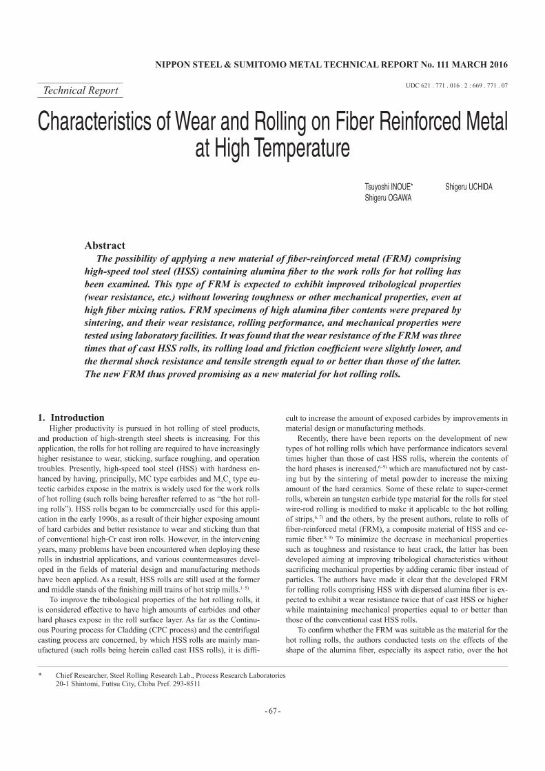
Figure 1 shows sectional photomicrographs of the specimens thus obtained. Whereas in the specimen of HSS and alumina fiber (part (a)), where the fiber shape was well preserved and the adhe-sion of the metal matrix (C) to the fiber (A) was good, in that of HSS and SiC fiber (part (b)), the fiber was deformed and there were defects presumably caused by some reaction between the metal ma-trix (C) and the fiber (B); see the voids indicated with white arrows at the metal/fiber interfaces. Based on this finding, alumina fiber was selected for the trial manufacture of the specimens for the tests reported in this work.
The alumina fiber used for the test FRM roll to examine the suit-ability of the material for the hot rolling rolls was defined as fol-lows: purity 95% or more; ratio of α phase roughly 50% or more; and shape 8 to 10 μm in diameter with an aspect ratio of roughly 50, or 3 to 7 μm in diameter with an aspect ratio of 20 to 40 by crushing in a ball mill. The alumina fiber in either of the above two different shapes was added to the HSS powder at a concentration of 20 vol-ume %, and the powders were then thoroughly mixed into a homo-geneous mixture. The mixture was then sintered at 1 000°C for about 3 hours under a pressure of 98 MPa using a hot isostatic press (HIP), and the sintered pieces were subjected to the same heat treat-
ment as that for cast HSS rolls. The specimens were machined and set in test rolls. The heat treatment condition was set such that the Shore hardness of the FRM specimens would be 83 to 86, approxi-mately the same as that of the cast HSS rolls.
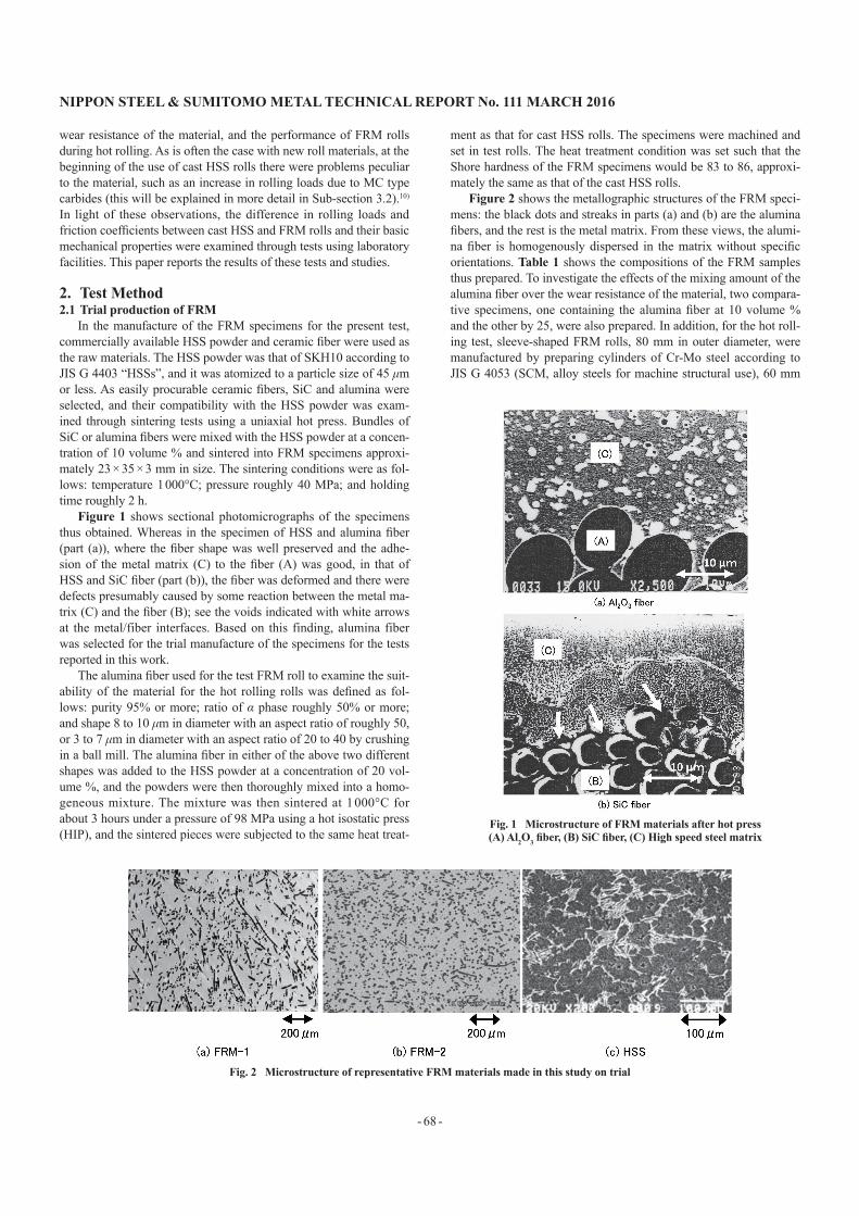
Figure 2 shows the metallographic structures of the FRM speci-mens: the black dots and streaks in parts (a) and (b) are the alumina fibers, and the rest is the metal matrix. From these views, the alumi-na fiber is homogenously dispersed in the matrix without specific orientations. Table 1 shows the compositions of the FRM samples thus prepared. To investigate the effects of the mixing amount of the alumina fiber over the wear resistance of the material, two compara-tive specimens, one containing the alumina fiber at 10 volume % and the other by 25, were also prepared. In addition, for the hot roll-ing test, sleeve-shaped FRM rolls, 80 mm in outer diameter, were manufactured by preparing cylinders of Cr-Mo steel according to JIS G 4053 (SCM, alloy steels for machine structural use), 60 mm
Fig. 1 Microstructure of FRM materials after hot press(A) Al2O3 fiber, (B) SiC fiber, (C) High speed steel matrix
Fig. 2 Microstructure of representative FRM materials made in this study on trial
NIPPON STEEL & SUMITOMO METAL TECHNICAL REPORT No. 111 MARCH 2016
- 69 -
in outer diameter, 45 mm in inner diameter and 100 mm in length, and cladding their outer surfaces with a layer, roughly 10 mm in thickness, of the FRM of different compositions by the HIP.2.2 Test equipment and conditions
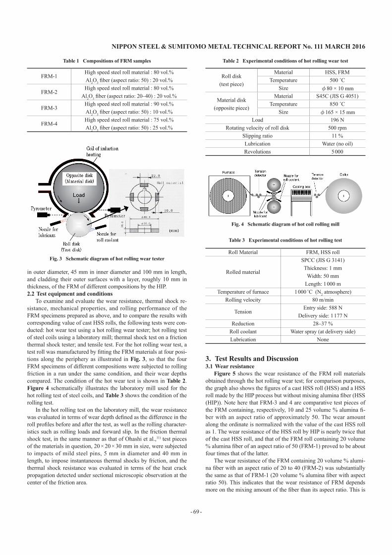
To examine and evaluate the wear resistance, thermal shock re-sistance, mechanical properties, and rolling performance of the FRM specimens prepared as above, and to compare the results with corresponding value of cast HSS rolls, the following tests were con-ducted: hot wear test using a hot rolling wear tester; hot rolling test of steel coils using a laboratory mill; thermal shock test on a friction thermal shock tester; and tensile test. For the hot rolling wear test, a test roll was manufactured by fitting the FRM materials at four posi-tions along the periphery as illustrated in Fig. 3, so that the four FRM specimens of different compositions were subjected to rolling friction in a run under the same condition, and their wear depths compared. The condition of the hot wear test is shown in Table 2. Figure 4 schematically illustrates the laboratory mill used for the hot rolling test of steel coils, and Table 3 shows the condition of the rolling test.
In the hot rolling test on the laboratory mill, the wear resistance was evaluated in terms of wear depth defined as the difference in the roll profiles before and after the test, as well as the rolling character-istics such as rolling loads and forward slip. In the friction thermal shock test, in the same manner as that of Ohashi et al.,11) test pieces of the materials in question, 20 × 20 × 30 mm in size, were subjected to impacts of mild steel pins, 5 mm in diameter and 40 mm in length, to impose instantaneous thermal shocks by friction, and the thermal shock resistance was evaluated in terms of the heat crack propagation detected under sectional microscopic observation at the center of the friction area.
3. Test Results and Discussion3.1 Wear resistance
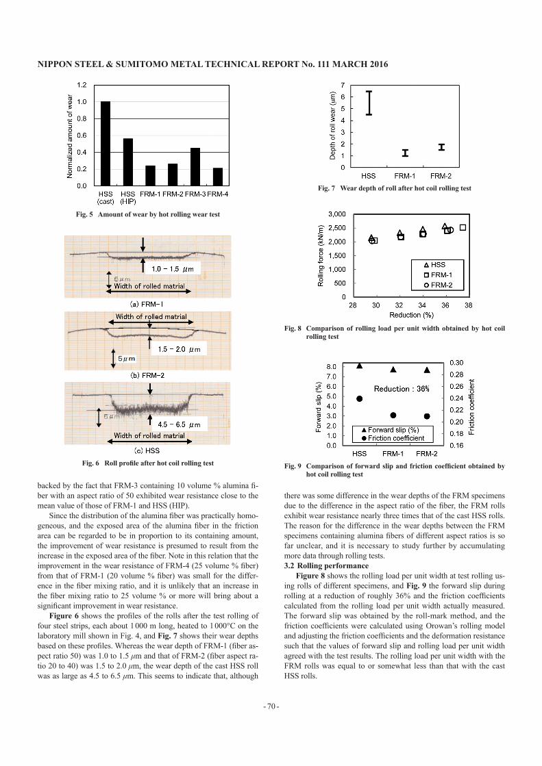
Figure 5 shows the wear resistance of the FRM roll materials obtained through the hot rolling wear test; for comparison purposes, the graph also shows the figures of a cast HSS roll (HSS) and a HSS roll made by the HIP process but without mixing alumina fiber (HSS (HIP)). Note here that FRM-3 and 4 are comparative test pieces of the FRM containing, respectively, 10 and 25 volume % alumina fi-ber with an aspect ratio of approximately 50. The wear amount along the ordinate is normalized with the value of the cast HSS roll as 1. The wear resistance of the HSS roll by HIP is nearly twice that of the cast HSS roll, and that of the FRM roll containing 20 volume % alumina fiber of an aspect ratio of 50 (FRM-1) proved to be about four times that of the latter.
The wear resistance of the FRM containing 20 volume % alumi-na fiber with an aspect ratio of 20 to 40 (FRM-2) was substantially the same as that of FRM-1 (20 volume % alumina fiber with aspect ratio 50). This indicates that the wear resistance of FRM depends more on the mixing amount of the fiber than its aspect ratio. This is
Table 2 Experimental conditions of hot rolling wear test
Roll disk(test piece)
Material HSS, FRMTemperature 500 ˚C
Size φ80 × 10 mm
Material disk(opposite piece)
Material S45C (JIS G 4051)Temperature 850 ˚C
Size φ165 × 15 mmLoad 196 N
Rotating velocity of roll disk 500 rpmSlipping ratio 11 %Lubrication Water (no oil)Revolutions 5 000
Table 1 Compositions of FRM samples
FRM-1High speed steel roll material : 80 vol.%Al2O3 fiber (aspect ratio: 50) : 20 vol.%
FRM-2High speed steel roll material : 80 vol.%
Al2O3 fiber (aspect ratio: 20–40) : 20 vol.%
FRM-3High speed steel roll material : 90 vol.%Al2O3 fiber (aspect ratio: 50) : 10 vol.%
FRM-4High speed steel roll material : 75 vol.%Al2O3 fiber (aspect ratio: 50) : 25 vol.%
Fig. 3 Schematic diagram of hot rolling wear tester
Fig. 4 Schematic diagram of hot coil rolling mill
Table 3 Experimental conditions of hot rolling test
Roll Material FRM, HSS roll
Rolled material
SPCC (JIS G 3141)Thickness: 1 mm
Width: 50 mmLength: 1 000 m
Temperature of furnace 1 000 ˚C (N2 atmosphere)Rolling velocity 80 m/min
TensionEntry side: 588 N
Delivery side: 1 177 NReduction 28–37 %
Roll coolant Water spray (at delivery side)Lubrication None
NIPPON STEEL & SUMITOMO METAL TECHNICAL REPORT No. 111 MARCH 2016
- 70 -
backed by the fact that FRM-3 containing 10 volume % alumina fi-ber with an aspect ratio of 50 exhibited wear resistance close to the mean value of those of FRM-1 and HSS (HIP).
Since the distribution of the alumina fiber was practically homo-geneous, and the exposed area of the alumina fiber in the friction area can be regarded to be in proportion to its containing amount, the improvement of wear resistance is presumed to result from the increase in the exposed area of the fiber. Note in this relation that the improvement in the wear resistance of FRM-4 (25 volume % fiber) from that of FRM-1 (20 volume % fiber) was small for the differ-ence in the fiber mixing ratio, and it is unlikely that an increase in the fiber mixing ratio to 25 volume % or more will bring about a significant improvement in wear resistance.
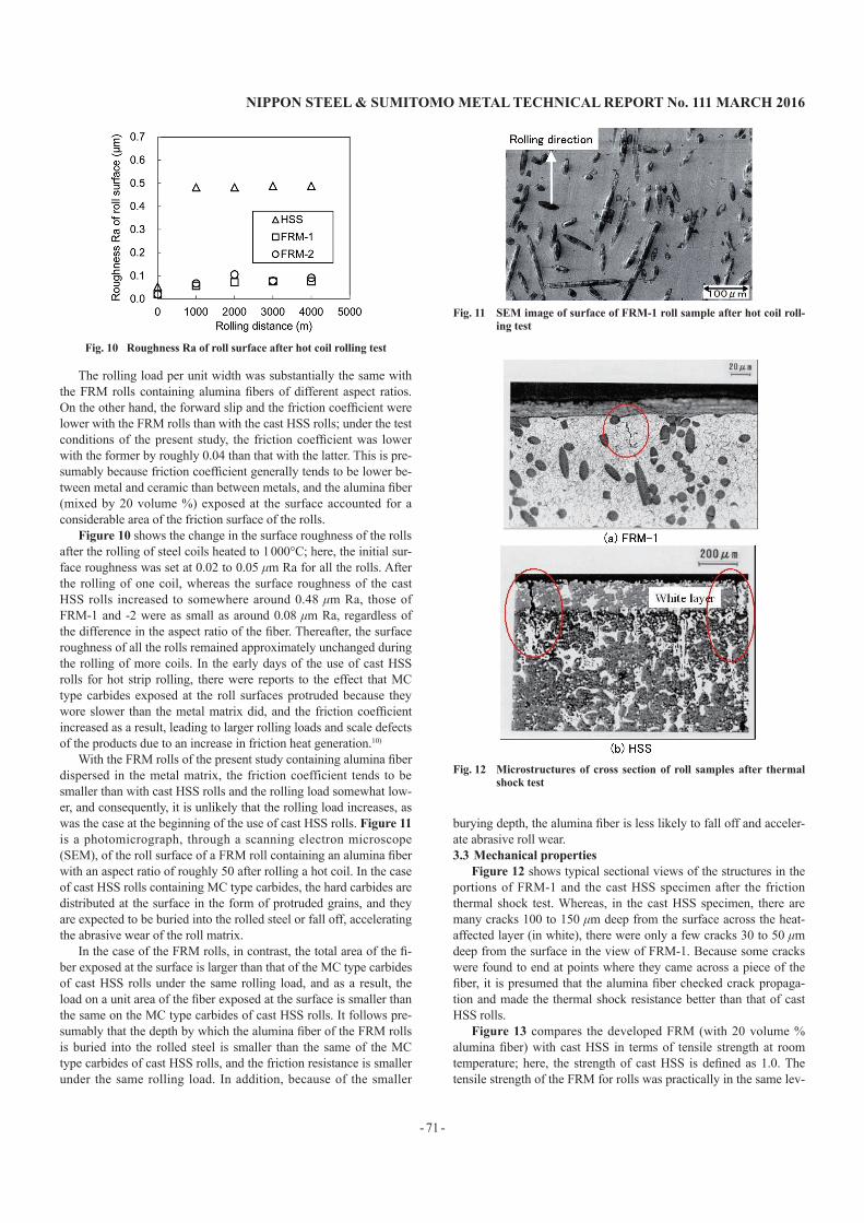
Figure 6 shows the profiles of the rolls after the test rolling of four steel strips, each about 1 000 m long, heated to 1 000°C on the laboratory mill shown in Fig. 4, and Fig. 7 shows their wear depths based on these profiles. Whereas the wear depth of FRM-1 (fiber as-pect ratio 50) was 1.0 to 1.5 μm and that of FRM-2 (fiber aspect ra-tio 20 to 40) was 1.5 to 2.0 μm, the wear depth of the cast HSS roll was as large as 4.5 to 6.5 μm. This seems to indicate that, although
there was some difference in the wear depths of the FRM specimens due to the difference in the aspect ratio of the fiber, the FRM rolls exhibit wear resistance nearly three times that of the cast HSS rolls. The reason for the difference in the wear depths between the FRM specimens containing alumina fibers of different aspect ratios is so far unclear, and it is necessary to study further by accumulating more data through rolling tests.3.2 Rolling performance
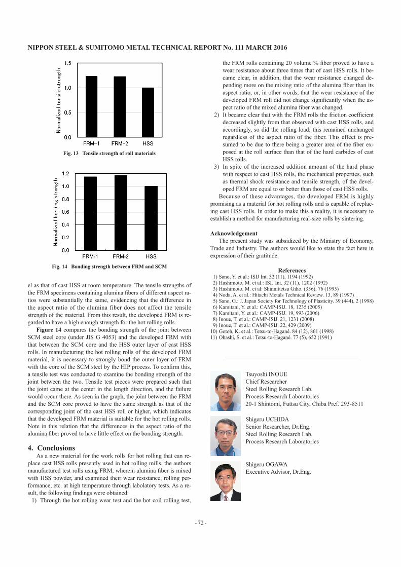
Figure 8 shows the rolling load per unit width at test rolling us-ing rolls of different specimens, and Fig. 9 the forward slip during rolling at a reduction of roughly 36% and the friction coefficients calculated from the rolling load per unit width actually measured. The forward slip was obtained by the roll-mark method, and the friction coefficients were calculated using Orowan’s rolling model and adjusting the friction coefficients and the deformation resistance such that the values of forward slip and rolling load per unit width agreed with the test results. The rolling load per unit width with the FRM rolls was equal to or somewhat less than that with the cast HSS rolls.
Fig. 5 Amount of wear by hot rolling wear test
Fig. 6 Roll profile after hot coil rolling test
Fig. 7 Wear depth of roll after hot coil rolling test
Fig. 8 Comparison of rolling load per unit width obtained by hot coil rolling test
Fig. 9 Comparison of forward slip and friction coefficient obtained by hot coil rolling test
NIPPON STEEL & SUMITOMO METAL TECHNICAL REPORT No. 111 MARCH 2016
- 71 -
The rolling load per unit width was substantially the same with the FRM rolls containing alumina fibers of different aspect ratios. On the other hand, the forward slip and the friction coefficient were lower with the FRM rolls than with the cast HSS rolls; under the test conditions of the present study, the friction coefficient was lower with the former by roughly 0.04 than that with the latter. This is pre-sumably because friction coefficient generally tends to be lower be-tween metal and ceramic than between metals, and the alumina fiber (mixed by 20 volume %) exposed at the surface accounted for a considerable area of the friction surface of the rolls.
Figure 10 shows the change in the surface roughness of the rolls after the rolling of steel coils heated to 1 000°C; here, the initial sur-face roughness was set at 0.02 to 0.05 μm Ra for all the rolls. After the rolling of one coil, whereas the surface roughness of the cast HSS rolls increased to somewhere around 0.48 μm Ra, those of FRM-1 and -2 were as small as around 0.08 μm Ra, regardless of the difference in the aspect ratio of the fiber. Thereafter, the surface roughness of all the rolls remained approximately unchanged during the rolling of more coils. In the early days of the use of cast HSS rolls for hot strip rolling, there were reports to the effect that MC type carbides exposed at the roll surfaces protruded because they wore slower than the metal matrix did, and the friction coefficient increased as a result, leading to larger rolling loads and scale defects of the products due to an increase in friction heat generation.10)
With the FRM rolls of the present study containing alumina fiber dispersed in the metal matrix, the friction coefficient tends to be smaller than with cast HSS rolls and the rolling load somewhat low-er, and consequently, it is unlikely that the rolling load increases, as was the case at the beginning of the use of cast HSS rolls. Figure 11 is a photomicrograph, through a scanning electron microscope (SEM), of the roll surface of a FRM roll containing an alumina fiber with an aspect ratio of roughly 50 after rolling a hot coil. In the case of cast HSS rolls containing MC type carbides, the hard carbides are distributed at the surface in the form of protruded grains, and they are expected to be buried into the rolled steel or fall off, accelerating the abrasive wear of the roll matrix.
In the case of the FRM rolls, in contrast, the total area of the fi-ber exposed at the surface is larger than that of the MC type carbides of cast HSS rolls under the same rolling load, and as a result, the load on a unit area of the fiber exposed at the surface is smaller than the same on the MC type carbides of cast HSS rolls. It follows pre-sumably that the depth by which the alumina fiber of the FRM rolls is buried into the rolled steel is smaller than the same of the MC type carbides of cast HSS rolls, and the friction resistance is smaller under the same rolling load. In addition, because of the smaller
burying depth, the alumina fiber is less likely to fall off and acceler-ate abrasive roll wear.3.3 Mechanical properties
Figure 12 shows typical sectional views of the structures in the portions of FRM-1 and the cast HSS specimen after the friction thermal shock test. Whereas, in the cast HSS specimen, there are many cracks 100 to 150 μm deep from the surface across the heat-affected layer (in white), there were only a few cracks 30 to 50 μm deep from the surface in the view of FRM-1. Because some cracks were found to end at points where they came across a piece of the fiber, it is presumed that the alumina fiber checked crack propaga-tion and made the thermal shock resistance better than that of cast HSS rolls.
Figure 13 compares the developed FRM (with 20 volume % alumina fiber) with cast HSS in terms of tensile strength at room temperature; here, the strength of cast HSS is defined as 1.0. The tensile strength of the FRM for rolls was practically in the same lev-
Fig. 10 Roughness Ra of roll surface after hot coil rolling test
Fig. 11 SEM image of surface of FRM-1 roll sample after hot coil roll-ing test
Fig. 12 Microstructures of cross section of roll samples after thermal shock test
NIPPON STEEL & SUMITOMO METAL TECHNICAL REPORT No. 111 MARCH 2016
- 72 -
el as that of cast HSS at room temperature. The tensile strengths of the FRM specimens containing alumina fibers of different aspect ra-tios were substantially the same, evidencing that the difference in the aspect ratio of the alumina fiber does not affect the tensile strength of the material. From this result, the developed FRM is re-garded to have a high enough strength for the hot rolling rolls.
Figure 14 compares the bonding strength of the joint between SCM steel core (under JIS G 4053) and the developed FRM with that between the SCM core and the HSS outer layer of cast HSS rolls. In manufacturing the hot rolling rolls of the developed FRM material, it is necessary to strongly bond the outer layer of FRM with the core of the SCM steel by the HIP process. To confirm this, a tensile test was conducted to examine the bonding strength of the joint between the two. Tensile test pieces were prepared such that the joint came at the center in the length direction, and the failure would occur there. As seen in the graph, the joint between the FRM and the SCM core proved to have the same strength as that of the corresponding joint of the cast HSS roll or higher, which indicates that the developed FRM material is suitable for the hot rolling rolls. Note in this relation that the differences in the aspect ratio of the alumina fiber proved to have little effect on the bonding strength.
4. ConclusionsAs a new material for the work rolls for hot rolling that can re-
place cast HSS rolls presently used in hot rolling mills, the authors manufactured test rolls using FRM, wherein alumina fiber is mixed with HSS powder, and examined their wear resistance, rolling per-formance, etc. at high temperature through labolatory tests. As a re-sult, the following findings were obtained:
1) Through the hot rolling wear test and the hot coil rolling test,
the FRM rolls containing 20 volume % fiber proved to have a wear resistance about three times that of cast HSS rolls. It be-came clear, in addition, that the wear resistance changed de-pending more on the mixing ratio of the alumina fiber than its aspect ratio, or, in other words, that the wear resistance of the developed FRM roll did not change significantly when the as-pect ratio of the mixed alumina fiber was changed.
2) It became clear that with the FRM rolls the friction coefficient decreased slightly from that observed with cast HSS rolls, and accordingly, so did the rolling load; this remained unchanged regardless of the aspect ratio of the fiber. This effect is pre-sumed to be due to there being a greater area of the fiber ex-posed at the roll surface than that of the hard carbides of cast HSS rolls.
3) In spite of the increased addition amount of the hard phase with respect to cast HSS rolls, the mechanical properties, such as thermal shock resistance and tensile strength, of the devel-oped FRM are equal to or better than those of cast HSS rolls.
Because of these advantages, the developed FRM is highly promising as a material for hot rolling rolls and is capable of replac-ing cast HSS rolls. In order to make this a reality, it is necessary to establish a method for manufacturing real-size rolls by sintering.
AcknowledgementThe present study was subsidized by the Ministry of Economy,
Trade and Industry. The authors would like to state the fact here in expression of their gratitude.
References1) Sano, Y. et al.: ISIJ Int. 32 (11), 1194 (1992)2) Hashimoto, M. et al.: ISIJ Int. 32 (11), 1202 (1992)3) Hashimoto, M. et al: Shinnittetsu Giho. (356), 76 (1995)4) Noda, A. et al.: Hitachi Metals Technical Review. 13, 89 (1997)5) Sano, G.: J. Japan Society for Technology of Plasticity. 39 (444), 2 (1998)6) Kamitani, Y. et al.: CAMP-ISIJ. 18, 1235 (2005)7) Kamitani, Y. et al.: CAMP-ISIJ. 19, 993 (2006)8) Inoue, T. et al.: CAMP-ISIJ. 21, 1231 (2008)9) Inoue, T. et al.: CAMP-ISIJ. 22, 429 (2009)
10) Gotoh, K. et al.: Tetsu-to-Hagané. 84 (12), 861 (1998)11) Ohashi, S. et al.: Tetsu-to-Hagané. 77 (5), 652 (1991)
Fig. 13 Tensile strength of roll materials
Fig. 14 Bonding strength between FRM and SCM
Tsuyoshi INOUEChief ResearcherSteel Rolling Research Lab.Process Research Laboratories20-1 Shintomi, Futtsu City, Chiba Pref. 293-8511
Shigeru UCHIDASenior Researcher, Dr.Eng.Steel Rolling Research Lab.Process Research Laboratories
Shigeru OGAWAExecutive Advisor, Dr.Eng.