Embed Size (px)
Citation preview

NIPPON STEEL & SUMITOMO METAL TECHNICAL REPORT No. 115 JULY 2017
- 47 -
1. IntroductionIn the case of the pile foundations of support structures of many
plant buildings and equipment, the footing and the ground beams connecting each footing are generally constructed at the top end po-sition of the pile. As the construction work involves many on-site labor works such as the formwork, re-bar, and the concrete pouring work, the construction work requires numerous work stages and construction terms. Therefore, the construction work has become la-bor-dependent-structured.
On the other hand, the on-site labor cost has increased since the 1990s due to the aging of skilled workers and the shortage of young workers. Therefore, with the aim of reducing the construction cost and shortening the construction term, Nippon Steel & Sumitomo Metal Corporation has developed the Sat-in Pile Foundation. This is a joining method of a column and a foundation steel pipe pile in which the inside of the steel pipe pile is filled in with concrete after the column is inserted into the steel pipe pile through its head. This structure acquired the certification of the Building Center of Japan in 2003 as Sat-in Pile Foundation (Certification No. BCJ Certifica-tion-FD0061-01) 1) and has been applied to more than 20 in-compa-ny and outside company projects. This article reports the designing method, loading test results, actual applications and the effects of the Sat-in Pile Foundation.
2. Outline of Sat-in Pile Foundation2.1 Outline of construction method
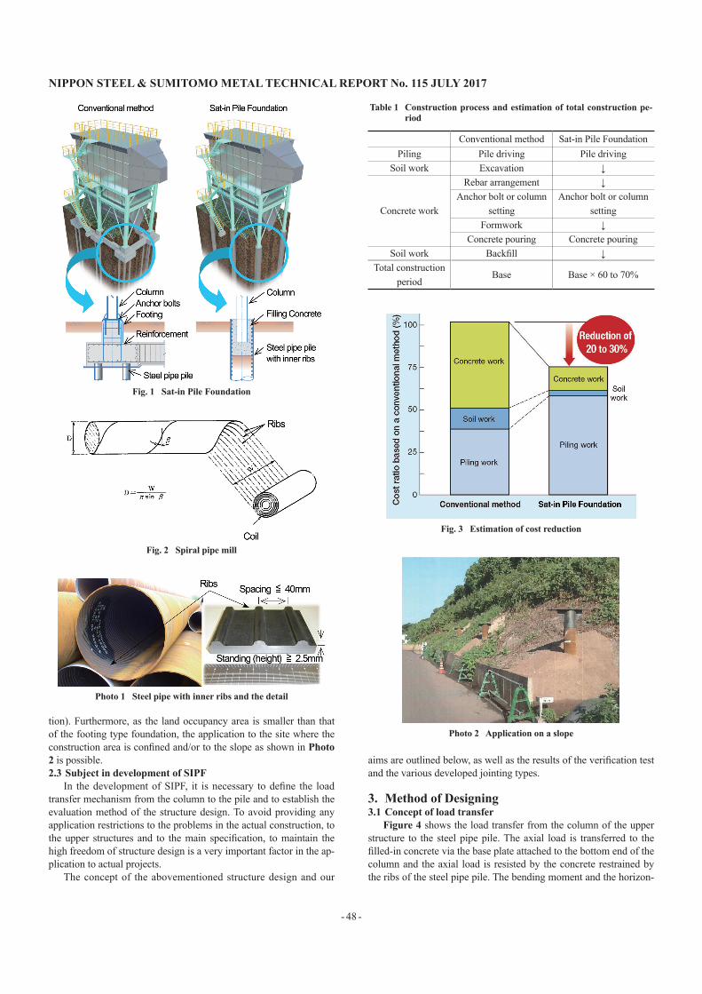
The construction method of the Sat-in Pile Foundation (herein-after referred to as “SIPF”) consists of three elements of the steel column, filling concrete (not reinforced) and the steel pipe pile as shown in Fig. 1. To construct the structure that transfers the load from the upper structure securely, the steel column is inserted into the steel pipe pile, which is filled in with concrete. For the steel pipe pile, the internally-ribbed steel pipe pile (specified in JIS A 5525 Annex A) is used to secure the bonding of the concrete to the steel pipe pile to strengthen the integrity of the steel pipe pile and the concrete. This steel pipe is produced by the spiral pipe forming method as shown in Fig. 2, using the rolled coiled steel strip sheet that has the ribs standing 2.5 mm high or above and arranged at in-tervals of 40 mm or less as shown in Photo 1. 2.2 Characteristics of SIPF
In SIPF, as the column has to be incorporated into the steel pipe pile, the size of the steel pipe pile becomes larger than that of the conventional structure. However, the number of steel pipe piles can be reduced. Additionally, not only the labor-dependent type soil work and the concrete work (formwork, re-bar work), but also the volume of excavation are reduced (Table 1). As a result thereof, a 30–40% shortening of the construction term and a 20–30% reduc-tion of the total cost of the foundation construction as shown in Fig. 3 can be realized (based on actual results of in-company construc-
Technical Report UDC 624.154.7
Development and Application of Sat-in Pile FoundationHiroko NAITO* Yoshihiro TAKANOYuzo AKASHI Masato TSUJIIYoshinori KABAYAMA Shinji TAENAKAYoshiro ISHIHAMA
AbstractConventional pile foundations for plant equipment such as frame structures are designed
with a concrete footing and ground beams connecting each. Therefore, the construction process depends on on-site labor, since it involves formwork, re-bar work and concrete pouring at the site, which means there are numerous work stages and requires long con-struction time. The Sat-in Pile Foundation has been developed by Nippon Steel & Sumitomo Metal Corporation, capable of saving labor required concrete works at site, achieving effi-ciency and shortening construction term. This paper introduces the developed pile founda-tion, composed of just one steel pipe pile with protrusions on the inner surfaces and filling concrete for one column.
* Manager, Civil Engineering Dept., Civil Engineering Div., Plant Engineering and Facility Management Center 20-1 Shintomi, Futtsu City, Chiba Pref. 293-8511
NIPPON STEEL & SUMITOMO METAL TECHNICAL REPORT No. 115 JULY 2017
- 48 -
tion). Furthermore, as the land occupancy area is smaller than that of the footing type foundation, the application to the site where the construction area is confined and/or to the slope as shown in Photo 2 is possible. 2.3 Subject in development of SIPF
In the development of SIPF, it is necessary to define the load transfer mechanism from the column to the pile and to establish the evaluation method of the structure design. To avoid providing any application restrictions to the problems in the actual construction, to the upper structures and to the main specification, to maintain the high freedom of structure design is a very important factor in the ap-plication to actual projects.
The concept of the abovementioned structure design and our
aims are outlined below, as well as the results of the verification test and the various developed jointing types.
3. Method of Designing3.1 Concept of load transfer
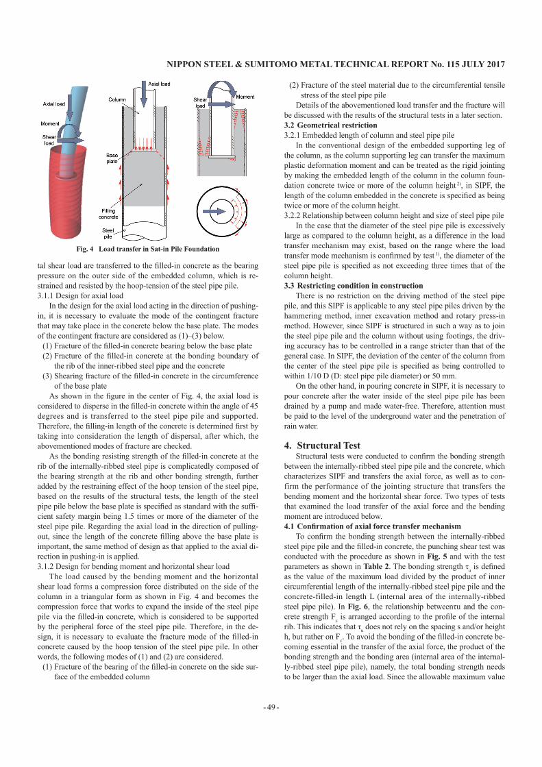
Figure 4 shows the load transfer from the column of the upper structure to the steel pipe pile. The axial load is transferred to the filled-in concrete via the base plate attached to the bottom end of the column and the axial load is resisted by the concrete restrained by the ribs of the steel pipe pile. The bending moment and the horizon-
Fig. 1 Sat-in Pile Foundation
Photo 1 Steel pipe with inner ribs and the detail
Fig. 2 Spiral pipe mill
Photo 2 Application on a slope
Table 1 Construction process and estimation of total construction pe-riod
Conventional method Sat-in Pile FoundationPiling Pile driving Pile driving
Soil work Excavation ↓
Concrete work
Rebar arrangement ↓Anchor bolt or column
settingAnchor bolt or column
settingFormwork ↓
Concrete pouring Concrete pouringSoil work Backfill ↓
Total construction period
Base Base × 60 to 70%
Fig. 3 Estimation of cost reduction
NIPPON STEEL & SUMITOMO METAL TECHNICAL REPORT No. 115 JULY 2017
- 49 -
tal shear load are transferred to the filled-in concrete as the bearing pressure on the outer side of the embedded column, which is re-strained and resisted by the hoop-tension of the steel pipe pile. 3.1.1 Design for axial load
In the design for the axial load acting in the direction of pushing-in, it is necessary to evaluate the mode of the contingent fracture that may take place in the concrete below the base plate. The modes of the contingent fracture are considered as (1)–(3) below.
(1) Fracture of the filled-in concrete bearing below the base plate(2) Fracture of the filled-in concrete at the bonding boundary of
the rib of the inner-ribbed steel pipe and the concrete(3) Shearing fracture of the filled-in concrete in the circumference
of the base plateAs shown in the figure in the center of Fig. 4, the axial load is
considered to disperse in the filled-in concrete within the angle of 45 degrees and is transferred to the steel pipe pile and supported. Therefore, the filling-in length of the concrete is determined first by taking into consideration the length of dispersal, after which, the abovementioned modes of fracture are checked.
As the bonding resisting strength of the filled-in concrete at the rib of the internally-ribbed steel pipe is complicatedly composed of the bearing strength at the rib and other bonding strength, further added by the restraining effect of the hoop tension of the steel pipe, based on the results of the structural tests, the length of the steel pipe pile below the base plate is specified as standard with the suffi-cient safety margin being 1.5 times or more of the diameter of the steel pipe pile. Regarding the axial load in the direction of pulling-out, since the length of the concrete filling above the base plate is important, the same method of design as that applied to the axial di-rection in pushing-in is applied. 3.1.2 Design for bending moment and horizontal shear load
The load caused by the bending moment and the horizontal shear load forms a compression force distributed on the side of the column in a triangular form as shown in Fig. 4 and becomes the compression force that works to expand the inside of the steel pipe pile via the filled-in concrete, which is considered to be supported by the peripheral force of the steel pipe pile. Therefore, in the de-sign, it is necessary to evaluate the fracture mode of the filled-in concrete caused by the hoop tension of the steel pipe pile. In other words, the following modes of (1) and (2) are considered.
(1) Fracture of the bearing of the filled-in concrete on the side sur-face of the embedded column
(2) Fracture of the steel material due to the circumferential tensile stress of the steel pipe pile
Details of the abovementioned load transfer and the fracture will be discussed with the results of the structural tests in a later section. 3.2 Geometrical restriction3.2.1 Embedded length of column and steel pipe pile
In the conventional design of the embedded supporting leg of the column, as the column supporting leg can transfer the maximum plastic deformation moment and can be treated as the rigid jointing by making the embedded length of the column in the column foun-dation concrete twice or more of the column height 2), in SIPF, the length of the column embedded in the concrete is specified as being twice or more of the column height. 3.2.2 Relationship between column height and size of steel pipe pile
In the case that the diameter of the steel pipe pile is excessively large as compared to the column height, as a difference in the load transfer mechanism may exist, based on the range where the load transfer mode mechanism is confirmed by test 1), the diameter of the steel pipe pile is specified as not exceeding three times that of the column height. 3.3 Restricting condition in construction
There is no restriction on the driving method of the steel pipe pile, and this SIPF is applicable to any steel pipe piles driven by the hammering method, inner excavation method and rotary press-in method. However, since SIPF is structured in such a way as to join the steel pipe pile and the column without using footings, the driv-ing accuracy has to be controlled in a range stricter than that of the general case. In SIPF, the deviation of the center of the column from the center of the steel pipe pile is specified as being controlled to within 1/10 D (D: steel pipe pile diameter) or 50 mm.
On the other hand, in pouring concrete in SIPF, it is necessary to pour concrete after the water inside of the steel pipe pile has been drained by a pump and made water-free. Therefore, attention must be paid to the level of the underground water and the penetration of rain water.
4. Structural TestStructural tests were conducted to confirm the bonding strength
between the internally-ribbed steel pipe pile and the concrete, which characterizes SIPF and transfers the axial force, as well as to con-firm the performance of the jointing structure that transfers the bending moment and the horizontal shear force. Two types of tests that examined the load transfer of the axial force and the bending moment are introduced below. 4.1Confirmationofaxialforcetransfermechanism
To confirm the bonding strength between the internally-ribbed steel pipe pile and the filled-in concrete, the punching shear test was conducted with the procedure as shown in Fig. 5 and with the test parameters as shown in Table 2. The bonding strength τu is defined as the value of the maximum load divided by the product of inner circumferential length of the internally-ribbed steel pipe pile and the concrete-filled-in length L (internal area of the internally-ribbed steel pipe pile). In Fig. 6, the relationship betweenτu and the con-crete strength Fc is arranged according to the profile of the internal rib. This indicates that τu does not rely on the spacing s and/or height h, but rather on Fc. To avoid the bonding of the filled-in concrete be-coming essential in the transfer of the axial force, the product of the bonding strength and the bonding area (internal area of the internal-ly-ribbed steel pipe pile), namely, the total bonding strength needs to be larger than the axial load. Since the allowable maximum value
Fig. 4 Load transfer in Sat-in Pile Foundation

NIPPON STEEL & SUMITOMO METAL TECHNICAL REPORT No. 115 JULY 2017
- 50 -
of the axial force is the product of Fc and the area Ac of the internal-ly-ribbed steel pipe pile with concrete, if the total bonding strength is made larger than that, bonding to the ribbed steel pipe does not fracture in advance by axial load. Then, from the formula (1) which satisfies the above, the relationship between the value obtained by the formulae (1) and the ratio of the bonding length L vs. the steel pipe diameter D is shown in Fig. 7.
{Fc × (1/4) πDin2}/ (πDinLτu) ≤ 1 (1)
where Fc : standard design strength of concrete (MPa), Din : steel pipe diameter (mm) after subtraction by the pipe thickness and the height of the rib, L: filled-in concrete length (mm), τu : bonding strength (MPa). In order for the value on the vertical axis to become 1.0 or below where the bonding fracture does not take place in ad-vance, a bonding length of 1.5 times or larger than the pipe diameter must be secured. From this, in SIPF, as the standard for the filled-in concrete length, it is specified that a length longer than 1.5 times or more of the pile diameter must be secured below the base plate. 4.2Confirmationoftransfermechanismofbendingmoment
To clarify the load transfer mechanism and the load bearing ca-pacity of the jointing section when a column is embedded in a steel
pipe pile, a test sample of a steel pipe pile of 1 200 mm in diameter × 9 mm thickness jointed with a steel pipe column of 900 mm in di-ameter × 16 mm thickness was built, and a bending test was con-ducted. As shown in Fig. 8, the bending moment acted upon the test sample at four points, namely at the loading points on the jointing section and at the supporting points. In the test, to expedite the frac-ture at the joint section, the embedding depth was shortened to 1.5 times that of the column height. Furthermore, to prevent the yield-ing of the column ahead of the fracture at the joint section, the col-umn was filled-in with concrete at the joint-section.
In Fig. 9, the relationship between the load and the displacement at point A is shown. The process of yielding at each point is as fol-lows. First, the tensile strain in the axial direction of the steel col-umn of 900 mm in deameter yielded at 2 242 kN, followed by the yielding of the tensile strain in the axial direction of the steel pipe pile of 1 200 mm in deameter at 2 443 kN. Thereafter, the strain in the circumferential direction at the top end of the steel pipe pile of 1 200 mm in deameter yielded at 3 204 kN. It was confirmed that the load bearing capacity of the joint section is higher than the yielding load bearing capacity of the column and the steel pipe pile and the yielding of the steel pipe pile, the hoop tension of which restrains
Table 2 Case of punching shear tests
Diameter of steel pipe D (mm) 250, 400, 600Height of shear keys h (mm) 2.5, 3.0, 4.1Spacing of shear keys s (mm) 36, 40Compressive strength of concrete Fcu (MPa) 25 to 50Angle of ribs θ (deg.) 0, 30, 40
Fig. 5 Outline of the punching shear test
Fig. 6 Bonding strength of the interface between concrete and steel pipe with ribs
Fig. 7 Relationship of concrete length to the failure mode
Fig. 8 Outline of the bending test

NIPPON STEEL & SUMITOMO METAL TECHNICAL REPORT No. 115 JULY 2017
- 51 -
the bending moment and the horizontal shear force occurred later than the occurrence of the yielding of the steel pipe pile in the axial direction. From this, it was revealed that as long as the dimensions of the joint section are secured, the joint section is not essential and the ordinary design of the column and the steel pipe pile is accept-able.
Figure 10 shows the distribution in the axial direction of the strain in the circumferential direction of the steel pipe pile of 1 200 mm in deameter at the time when the steel column of 900 mm in deameter yielded in the axial direction at the load of 2 242 kN. With respect to the center position of the embedded column, as the trian-gular pattern of the strain distribution of the bottom side of the steel pipe pile takes the opposite form when compared with that on the top side of the steel pipe pile, the column rotates around the center point of the embedded column and the compressive stress developed on the side of the column and distributed in a triangular form is transferred to the pile in a triangular form via the concrete, confirm-ing the appropriateness of the load transfer mechanism shown on the right side figure in Fig. 4.
This test revealed that appropriate designing such as making the embedded length of the column sufficient would allow the embed-ded column to yield prior to the yielding of the joint section, and also would prevent the joint section from being in a critical state.
5. Joint TypeMany of the plant support structures are designed so as to bear
horizontal forces with a diagonal brace. In this case, the foot of the column is pin-jointed and axial loads and/or horizontal loads are large, and large bending moments do not occur. Furthermore, with the assortment of only the rigid jointing of the embedded column, SIPF is unable to fully enjoy the advantage of shortening the con-struction term as the erection of the support structure on-site and the process of fixing the column leg part with concrete are very compli-cated. Taking this into consideration and with due attention paid to the characteristics of the support structure, the types of joint as shown in Table 3 have been developed.
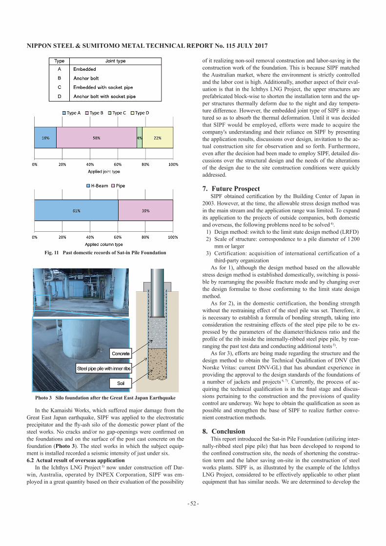
Firstly, in terms of jointing structure, there are two types. One is the embedded joint type of rigid jointing of the upper structure with the lower structure; the other type is the anchor bolt joint type of pin-jointing. In SIPF, the column and/or the base plate have to be incorporated into the steel pipe pile geometrically. Therefore, de-pending on the sizes of the column and/or the base plate, a steel pipe pile whose diameter is larger than that required of a pile has to be used, affording inefficient design. To solve the problem, a socket pipe jointing structure has also been developed: The structure uses a socket pipe made of an internally-ribbed steel pipe having a diame-ter slightly larger than that of the steel pipe pile to join the column and the steel pipe pile. In this type, for the column leg joint struc-ture, two types of embedded joint and anchor bolt joint are provided and either of them is separately applicable depending on the load on the supporting structures, interactive conditions, dimensional condi-tion and so forth. Thus, rational and efficient design is realized. At the early stage of the development, the object of the development was the steel pipe column. However, applications to the H-section steel column have increased to many applications and SIPF is appli-cable to both rectangular and circular shaped base plates.
Figure 11 shows the share percentage of the applied joint types and the column types. This indicates that the actual result of the share percentage of the anchor bolt joint type with the H-section steel pile is the highest.
6. Actual Result of Application6.1 Actual result of domestic application
The one column/one pile structure has been applied to the foun-dations of many in-company plants such as electrostatic precipita-tors, silos, and piping and wiring supporting structures that are sup-ported by steel columns. Now the number of the applications has reached well over approximately 20 projects (approximately 360 piles) since 1994 and has contributed to the shortening of the con-struction term and the reduction in cost.
Fig. 10 Axialdirectiondistributionofthestraininthecircumferentialdirection
Fig. 9 Relationship between load and displacement
Table 3 Joint type of Sat-in Pile Foundation
Joint type
Embedded Anchor boltEmbedded
with socket pipeAnchor bolt
with socket pipe
NIPPON STEEL & SUMITOMO METAL TECHNICAL REPORT No. 115 JULY 2017
- 52 -
In the Kamaishi Works, which suffered major damage from the Great East Japan earthquake, SIPF was applied to the electrostatic precipitator and the fly-ash silo of the domestic power plant of the steel works. No cracks and/or no gap-openings were confirmed on the foundations and on the surface of the post cast concrete on the foundation (Photo 3). The steel works in which the subject equip-ment is installed recorded a seismic intensity of just under six. 6.2 Actual result of overseas application
In the Ichthys LNG Project 3) now under construction off Dar-win, Australia, operated by INPEX Corporation, SIPF was em-ployed in a great quantity based on their evaluation of the possibility
of it realizing non-soil removal construction and labor-saving in the construction work of the foundation. This is because SIPF matched the Australian market, where the environment is strictly controlled and the labor cost is high. Additionally, another aspect of their eval-uation is that in the Ichthys LNG Project, the upper structures are prefabricated block-wise to shorten the installation term and the up-per structures thermally deform due to the night and day tempera-ture difference. However, the embedded joint type of SIPF is struc-tured so as to absorb the thermal deformation. Until it was decided that SIPF would be employed, efforts were made to acquire the company's understanding and their reliance on SIPF by presenting the application results, discussions over design, invitation to the ac-tual construction site for observation and so forth. Furthermore, even after the decision had been made to employ SIPF, detailed dis-cussions over the structural design and the needs of the alterations of the design due to the site construction conditions were quickly addressed.
7. Future ProspectSIPF obtained certification by the Building Center of Japan in
2003. However, at the time, the allowable stress design method was in the main stream and the application range was limited. To expand its application to the projects of outside companies, both domestic and overseas, the following problems need to be solved 4).
1) Deign method: switch to the limit state design method (LRFD) 2) Scale of structure: correspondence to a pile diameter of 1 200
mm or larger3) Certification: acquisition of international certification of a
third-party organizationAs for 1), although the design method based on the allowable
stress design method is established domestically, switching is possi-ble by rearranging the possible fracture mode and by changing over the design formulae to those conforming to the limit state design method.
As for 2), in the domestic certification, the bonding strength without the restraining effect of the steel pile was set. Therefore, it is necessary to establish a formula of bonding strength, taking into consideration the restraining effects of the steel pipe pile to be ex-pressed by the parameters of the diameter/thickness ratio and the profile of the rib inside the internally-ribbed steel pipe pile, by rear-ranging the past test data and conducting additional tests 5).
As for 3), efforts are being made regarding the structure and the design method to obtain the Technical Qualification of DNV (Det Norske Vritas: current DNV-GL) that has abundant experience in providing the approval to the design standards of the foundations of a number of jackets and projects 6, 7). Currently, the process of ac-quiring the technical qualification is in the final stage and discus-sions pertaining to the construction and the provisions of quality control are underway. We hope to obtain the qualification as soon as possible and strengthen the base of SIPF to realize further conve-nient construction methods.
8. ConclusionThis report introduced the Sat-in Pile Foundation (utilizing inter-
nally-ribbed steel pipe pile) that has been developed to respond to the confined construction site, the needs of shortening the construc-tion term and the labor saving on-site in the construction of steel works plants. SIPF is, as illustrated by the example of the Ichthys LNG Project, considered to be effectively applicable to other plant equipment that has similar needs. We are determined to develop the
Photo 3 Silo foundation after the Great East Japan Earthquake
Fig. 11 Past domestic records of Sat-in Pile Foundation

NIPPON STEEL & SUMITOMO METAL TECHNICAL REPORT No. 115 JULY 2017
- 53 -
single pipe pile type and the hybrid structure with a concrete column to make effective use of the steel material through the in-company and outside company projects.
* “Sat-in Pile Foundation” is the registered trademark of Nippon Steel & Sumikin Engineering Co., Ltd.
References1) The Building Center of Japan (a General Incorporated Foundation): One
Column One Pile (Sat-in Pile) Evaluation of Resistance Force of Pile Head Joining Structure (BCJ Rating-FD0061-01). 2003
2) Architectural Institute of Japan: Guideline for Designing Jointing in Steel Structure. Second Version. Tokyo, Maruzen Co., Ltd. 2006. p. 298
3) JGC Corporation: Home Page, Actual Results http://www.jgc.com/jp/03_projects/01_epc_energy_chemical/03_lng_
pj_06.html4) Tatsuta, M. et al.: Nippon Steel & Sumitomo Metal Technical Report.
(113), 133 (2016)5) Taenaka, S. et al.: Steel Pipe with Roll-Formed Shear Keys and Their
Application in Foundation Systems. 10th Intl. Conf. on Advanced in Steel Concrete Composite and Hybrid Structures. Singapore, 2012.7
6) DNV: Service Specification-DNV-RP-A203-Technology Qualification7) DNV: Service Specification-DNV-OSS-401-Technology Qualification
Management
Hiroko NAITOManagerCivil Engineering Dept., Civil Engineering Div.Plant Engineering and Facility Management Center20-1 Shintomi, Futtsu City, Chiba Pref. 293-8511
Yoshinori KABAYAMASenior ManagerMarket Development Dept.Slag & Cement Div.
Yoshihiro TAKANOGeneral ManagerCivil Engineering Div.Plant Engineering and Facility Management Center
Shinji TAENAKASenior Researcher, Ph.D.Steel Structures Research Lab.Steel Research Laboratories
Yuzo AKASHISenior ManagerMarket Development Dept.Slag & Cement Div.
Yoshiro ISHIHAMASenior ResearcherSteel Structures Research Lab.Steel Research Laboratories
Masato TSUJIIGeneral Manager, Head of Div., Ph.D.Steel Structures Research Lab.Steel Research Laboratories