Embed Size (px)
Citation preview
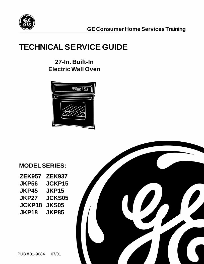
PUB # 31-9084 07/01
MODEL SERIES:
TECHNICAL SERVICE GUIDE
GE Consumer Home Services Training
27-In. Built-InElectric Wall Oven
ZEK957JKP56JKP45JKP27JCKP18JKP18
ZEK937JCKP15JKP15JCKS05JKS05JKP85
IMPORTANT SAFETY NOTICE The information in this service guide is intended for use byindividuals possessing adequate backgrounds of electrical,electronic, and mechanical experience. Any attempt to repair amajor appliance may result in personal injury and propertydamage. The manufacturer or seller cannot be responsible for theinterpretation of this information, nor can it assume any liability inconnection with its use.
WARNINGTo avoid personal injury, disconnect power before servicing this prod-uct. If electrical power is required for diagnosis or test purposes,disconnect the power immediately after performing the necessarychecks.
RECONNECT ALL GROUNDING DEVICESIf grounding wires, screws, straps, clips, nuts, or washers used tocomplete a path to ground are removed for service, they must bereturned to their original position and properly fastened.
GE Consumer Home Services TrainingTechnical Service Guide
Copyright © 2001
All rights reserved. This service guide may not be reproduced in whole or in partin any form without written permission from the General Electric Company.
!
– 1 –
Table of ContentsTable of Contents
Introduction ................................................................................................. 3
Nomenclature ............................................................................................. 4
Control Panel Features5 .............................................................................. 5
Component Locator Views ......................................................................... 11
Oven ......................................................................................................... 15
Lift-Off Oven Door ..................................................................................... 15
Door Assembly ........................................................................................... 15
Oven Door Gasket ..................................................................................... 16
Door Hinge Assemblies .............................................................................. 17
Door Hinge Replacement ........................................................................... 17
Component Compartment Airflow............................................................... 17
Electronic Oven Control System ................................................................ 18
Control Panel ............................................................................................. 18
Electronic Control (EC) .............................................................................. 18
Control Voltage .......................................................................................... 19
Key Panel Test ........................................................................................... 19
Ohmmeter Test .......................................................................................... 20
ERC Failure Codes .................................................................................... 21
Special Functions ...................................................................................... 23
Oven Sensor and Sensor Circuits ............................................................. 23
Oven Sensor and Door Switch Ohmmeter Test ......................................... 24
Sensor and Lock Switch Connectors ......................................................... 24
Oven Circuits............................................................................................. 25
Oven Calibration ........................................................................................ 25
Motorized Door Lock ................................................................................. 26
Oven Thermal Switch ................................................................................ 27
Lock Thermal Switch.................................................................................. 27
Fan Switch ................................................................................................. 27
Convection Bake Element and Fan Assembly ............................................ 28
– 2 –
Table of ContentsTable of Contents
Microwave ................................................................................................. 29
Microwave Removal ................................................................................. 30
Microwave Outer Case Removal .............................................................. 30
Microwave Door ....................................................................................... 30
Microwave Control Panel ......................................................................... 31
Microwave Power Control Board (PCB) ................................................... 32
Microwave Low-Voltage Transformer ....................................................... 32
Microwave Key Panel Test ....................................................................... 33
Microwave High-Voltage Capacitor ........................................................... 33
Microwave High-Voltage Diode ................................................................ 34
Microwave High-Voltage Transformer ...................................................... 35
Microwave Magnetron .............................................................................. 35
Microwave Magnetron Fan ....................................................................... 36
Microwave Magnetron TCO ..................................................................... 36
Microwave Fan Thermal Switch ................................................................ 37
Microwave Fuse ....................................................................................... 37
Microwave Flame TCO ............................................................................. 37
Microwave Gas (Humidity) Sensor............................................................ 38
Microwave Interlocks and Monitor ........................................................... 38
Microwave Oven Lamp Assembly ............................................................. 40
Microwave Turntable Motor ..................................................................... 40
Microwave Performance Test ................................................................... 40
Microwave Leak Test ............................................................................... 40
Microwave Fault Codes ............................................................................ 41
Microwave Diagnostic Charts ................................................................... 42
Schematics and Wiring DiagramsX ............................................................ 45
Quizz ......................................................................................................... 66
Warrantiesx ............................................................................................... 67
– 3 –
Introduction
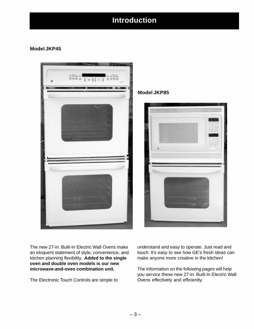
The new 27-in. Built-In Electric Wall Ovens makean eloquent statement of style, convenience, andkitchen planning flexibility. Added to the singleoven and double oven models is our newmicrowave-and-oven combination unit.
The Electronic Touch Controls are simple to
understand and easy to operate. Just read andtouch. It’s easy to see how GE’s fresh ideas canmake anyone more creative in the kitchen!
The information on the following pages will helpyou service these new 27-in. Built-In Electric WallOvens effectively and efficiently.
Model JKP45
Model JKP85
– 4 –
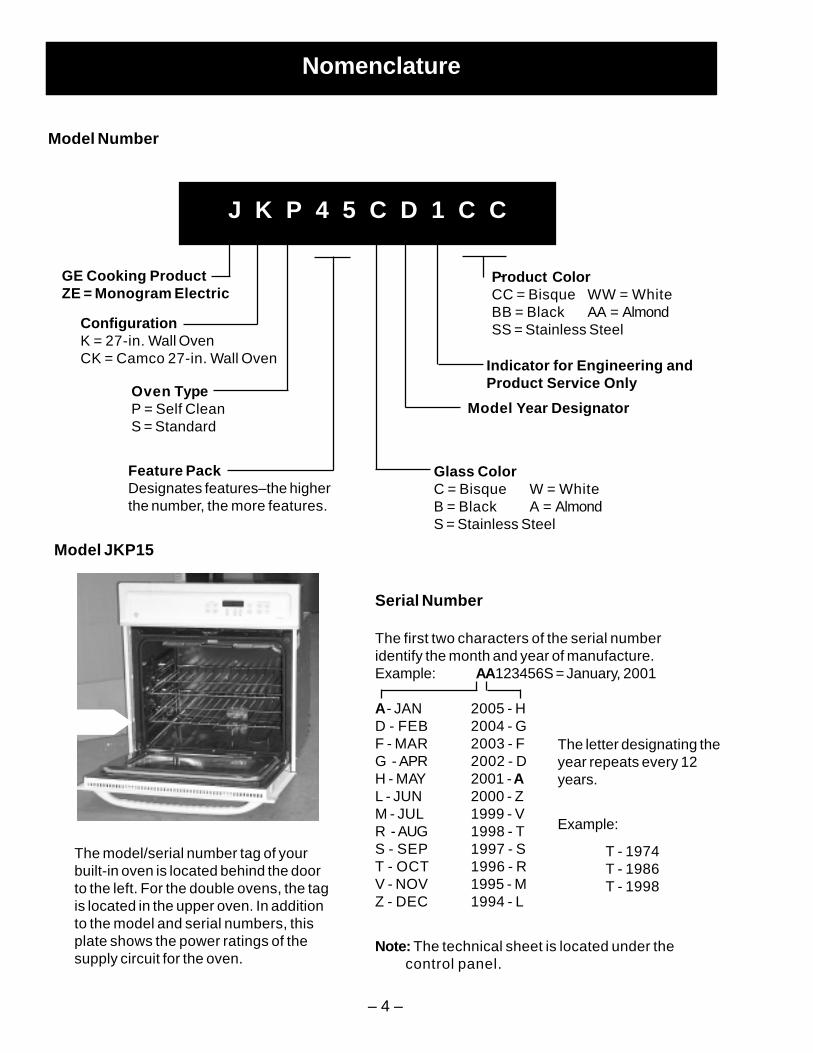
Feature PackDesignates features–the higherthe number, the more features.
Nomenclature
Model Number
Serial Number
The first two characters of the serial numberidentify the month and year of manufacture.Example: AA123456S = January, 2001
A - JAN 2005 - HD - FEB 2004 - GF - MAR 2003 - FG - APR 2002 - DH - MAY 2001 - AL - JUN 2000 - ZM - JUL 1999 - VR - AUG 1998 - TS - SEP 1997 - ST - OCT 1996 - RV - NOV 1995 - MZ - DEC 1994 - L
Note: The technical sheet is located under the control panel.
The letter designating theyear repeats every 12years.
Example:
T - 1974T - 1986T - 1998
J K P 4 5 C D 1 C C
GE Cooking ProductZE = Monogram Electric
ConfigurationK = 27-in. Wall OvenCK = Camco 27-in. Wall Oven
Oven TypeP = Self CleanS = Standard
Product ColorCC = Bisque WW = WhiteBB = Black AA = AlmondSS = Stainless Steel
Indicator for Engineering andProduct Service Only
The model/serial number tag of yourbuilt-in oven is located behind the doorto the left. For the double ovens, the tagis located in the upper oven. In additionto the model and serial numbers, thisplate shows the power ratings of thesupply circuit for the oven.
Model Year Designator
Glass ColorC = Bisque W = WhiteB = Black A = AlmondS = Stainless Steel
Model JKP15
– 5 –
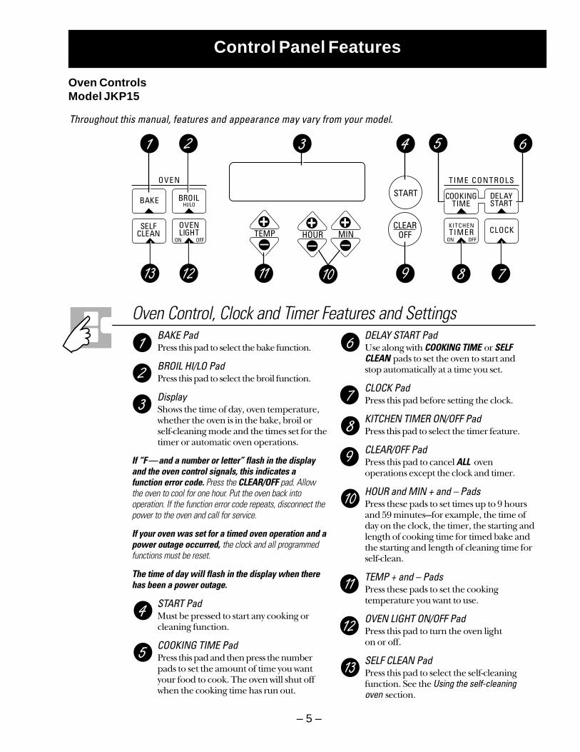
Control Panel Features
Throughout this manual, features and appearance may vary from your model.
Oven Control, Clock and Timer Features and SettingsBAKE PadPress this pad to select the bake function.
BROIL HI/LO PadPress this pad to select the broil function.
DisplayShows the time of day, oven temperature,whether the oven is in the bake, broil orself-cleaning mode and the times set for thetimer or automatic oven operations.
If “F—and a number or letter” flash in the displayand the oven control signals, this indicates afunction error code. Press the CLEAR/OFF pad. Allowthe oven to cool for one hour. Put the oven back intooperation. If the function error code repeats, disconnect thepower to the oven and call for service.
If your oven was set for a timed oven operation and apower outage occurred, the clock and all programmedfunctions must be reset.
The time of day will flash in the display when therehas been a power outage.
START PadMust be pressed to start any cooking orcleaning function.
COOKING TIME PadPress this pad and then press the numberpads to set the amount of time you wantyour food to cook. The oven will shut offwhen the cooking time has run out.
DELAY START PadUse along with COOKING TIME or SELFCLEAN pads to set the oven to start and stop automatically at a time you set.
CLOCK PadPress this pad before setting the clock.
KITCHEN TIMER ON/OFF PadPress this pad to select the timer feature.
CLEAR/OFF PadPress this pad to cancel ALL ovenoperations except the clock and timer.
HOUR and MIN + and – PadsPress these pads to set times up to 9 hoursand 59 minutes—for example, the time of day on the clock, the timer, the starting andlength of cooking time for timed bake andthe starting and length of cleaning time forself-clean.
TEMP + and – PadsPress these pads to set the cookingtemperature you want to use.
OVEN LIGHT ON/OFF PadPress this pad to turn the oven light on or off.
SELF CLEAN PadPress this pad to select the self-cleaningfunction. See the Using the self-cleaning oven section.
Oven ControlsModel JKP15
– 6 –
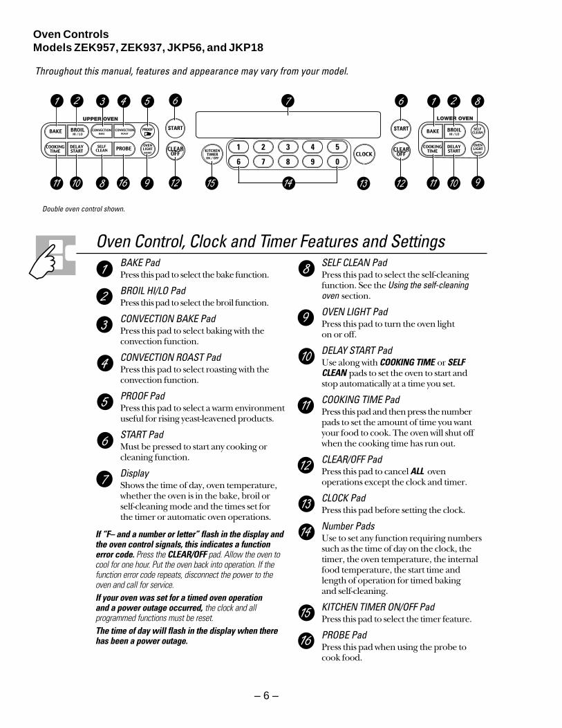
Oven ControlsModels ZEK957, ZEK937, JKP56, and JKP18
Throughout this manual, features and appearance may vary from your model.
UPPER OVEN LOWER OVEN
Oven Control, Clock and Timer Features and SettingsBAKE PadPress this pad to select the bake function.
BROIL HI/LO PadPress this pad to select the broil function.
CONVECTION BAKE PadPress this pad to select baking with theconvection function.
CONVECTION ROAST PadPress this pad to select roasting with theconvection function.
PROOF PadPress this pad to select a warm environmentuseful for rising yeast-leavened products.
START PadMust be pressed to start any cooking orcleaning function.
DisplayShows the time of day, oven temperature,whether the oven is in the bake, broil orself-cleaning mode and the times set for the timer or automatic oven operations.
If “F– and a number or letter” flash in the display andthe oven control signals, this indicates a functionerror code. Press the CLEAR/OFF pad. Allow the oven tocool for one hour. Put the oven back into operation. If thefunction error code repeats, disconnect the power to theoven and call for service.If your oven was set for a timed oven operation and a power outage occurred, the clock and allprogrammed functions must be reset. The time of day will flash in the display when therehas been a power outage.
SELF CLEAN PadPress this pad to select the self-cleaningfunction. See the Using the self-cleaningoven section.
OVEN LIGHT PadPress this pad to turn the oven light on or off.
DELAY START PadUse along with COOKING TIME or SELFCLEAN pads to set the oven to start and stop automatically at a time you set.
COOKING TIME PadPress this pad and then press the numberpads to set the amount of time you wantyour food to cook. The oven will shut offwhen the cooking time has run out.
CLEAR/OFF PadPress this pad to cancel ALL ovenoperations except the clock and timer.
CLOCK PadPress this pad before setting the clock.
Number PadsUse to set any function requiring numberssuch as the time of day on the clock, thetimer, the oven temperature, the internalfood temperature, the start time and length of operation for timed baking and self-cleaning.
KITCHEN TIMER ON/OFF PadPress this pad to select the timer feature.
PROBE PadPress this pad when using the probe to cook food.
Double oven control shown.
– 7 –
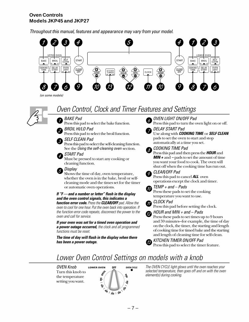
Oven ControlsModels JKP45 and JKP27
Oven Control, Clock and Timer Features and SettingsBAKE PadPress this pad to select the bake function.BROIL HI/LO PadPress this pad to select the broil function.SELF CLEAN PadPress this pad to select the self-cleaning function.See the Using the self-cleaning oven section.START PadMust be pressed to start any cooking orcleaning function.DisplayShows the time of day, oven temperature,whether the oven is in the bake, broil or self-cleaning mode and the times set for the timeror automatic oven operations.
If “F —and a number or letter” flash in the displayand the oven control signals, this indicates afunction error code. Press the CLEAR/OFF pad. Allow theoven to cool for one hour. Put the oven back into operation. Ifthe function error code repeats, disconnect the power to theoven and call for service.If your oven was set for a timed oven operation and a power outage occurred, the clock and all programmedfunctions must be reset. The time of day will flash in the display when therehas been a power outage.
OVEN LIGHT ON/OFF PadPress this pad to turn the oven light on or off.DELAY START PadUse along with COOKING TIME or SELF CLEANpads to set the oven to start and stopautomatically at a time you set.COOKING TIME PadPress this pad and then press the HOUR andMIN + and – pads to set the amount of timeyou want your food to cook. The oven willshut off when the cooking time has run out.CLEAR/OFF PadPress this pad to cancel ALL oven operations except the clock and timer.TEMP + and – PadsPress these pads to set the cookingtemperature you want to use.CLOCK PadPress this pad before setting the clock.HOUR and MIN + and – PadsPress these pads to set times up to 9 hoursand 59 minutes—for example, the time of dayon the clock, the timer, the starting and lengthof cooking time for timed bake and the startingand length of cleaning time for self-clean.KITCHEN TIMER ON/OFF PadPress this pad to select the timer feature.
(on some models)
Lower Oven Control Settings on models with a knobOVEN Knob Turn this knob tothe temperaturesetting you want.
The OVEN CYCLE light glows until the oven reaches yourselected temperature, then goes off and on with the oven element(s) during cooking.
Throughout this manual, features and appearance may vary from your model.
– 8 –
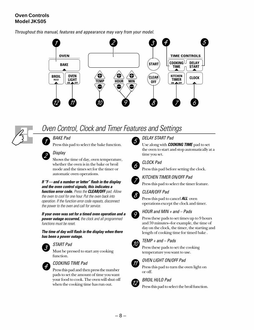
Oven ControlsModel JKS05
Throughout this manual, features and appearance may vary from your model.
Oven Control, Clock and Timer Features and SettingsBAKE PadPress this pad to select the bake function.
DisplayShows the time of day, oven temperature,whether the oven is in the bake or broilmode and the times set for the timer orautomatic oven operations.
If “F—and a number or letter” flash in the displayand the oven control signals, this indicates afunction error code. Press the CLEAR/OFF pad. Allowthe oven to cool for one hour. Put the oven back intooperation. If the function error code repeats, disconnect the power to the oven and call for service.
If your oven was set for a timed oven operation and apower outage occurred, the clock and all programmedfunctions must be reset.
The time of day will flash in the display when therehas been a power outage.
START PadMust be pressed to start any cookingfunction.
COOKING TIME PadPress this pad and then press the numberpads to set the amount of time you wantyour food to cook. The oven will shut offwhen the cooking time has run out.
DELAY START PadUse along with COOKING TIME pad to setthe oven to start and stop automatically at atime you set.
CLOCK PadPress this pad before setting the clock.
KITCHEN TIMER ON/OFF PadPress this pad to select the timer feature.
CLEAR/OFF PadPress this pad to cancel ALL ovenoperations except the clock and timer.
HOUR and MIN + and – PadsPress these pads to set times up to 9 hoursand 59 minutes—for example, the time ofday on the clock, the timer, the starting andlength of cooking time for timed bake .
TEMP + and – PadsPress these pads to set the cookingtemperature you want to use.
OVEN LIGHT ON/OFF PadPress this pad to turn the oven light onor off.
BROIL HI/LO PadPress this pad to select the broil function.
– 9 –
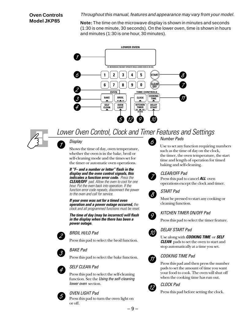
Oven ControlsModel JKP85
Lower Oven Control, Clock and Timer Features and SettingsDisplay
Shows the time of day, oven temperature,whether the oven is in the bake, broil orself-cleaning mode and the times set forthe timer or automatic oven operations.
If “F– and a number or letter” flash in thedisplay and the oven control signals, thisindicates a function error code. Press theCLEAR/OFF pad. Allow the oven to cool for onehour. Put the oven back into operation. If thefunction error code repeats, disconnect the powerto the oven and call for service.
If your oven was set for a timed ovenoperation and a power outage occurred, theclock and all programmed functions must be reset.
The time of day (may be incorrect) will flashin the display when the there has been apower outage.
BROIL HI/LO Pad
Press this pad to select the broil function.
BAKE Pad
Press this pad to select the bake function.
SELF CLEAN Pad
Press this pad to select the self-cleaningfunction. See the Using the self-cleaninglower oven section.
OVEN LIGHT PadPress this pad to turn the oven light on or off.
CLEAR/OFF PadPress this pad to cancel ALL oven operations except the clock and timer.
START Pad
Must be pressed to start any cooking orcleaning function.
KITCHEN TIMER ON/OFF Pad
Press this pad to select the timer feature.
DELAY START Pad
Use along with COOKING TIME or SELFCLEAN pads to set the oven to start and stop automatically at a time you set.
COOKING TIME Pad
Press this pad and then press the numberpads to set the amount of time you wantyour food to cook. The oven will shut offwhen the cooking time has run out.
CLOCK Pad
Press this pad before setting the clock.
Number Pads
Use to set any function requiring numberssuch as the time of day on the clock, the timer, the oven temperature, the starttime and length of operation for timedbaking and self-cleaning.
CLEAR/OFF PadPress this pad to cancel ALL oven operations except the clock and timer.
START Pad
Must be pressed to start any cooking orcleaning function.
KITCHEN TIMER ON/OFF Pad
Press this pad to select the timer feature.
DELAY START Pad
Use along with COOKING TIME or SELFCLEAN pads to set the oven to start and stop automatically at a time you set.
COOKING TIME Pad
Press this pad and then press the numberpads to set the amount of time you wantyour food to cook. The oven will shut offwhen the cooking time has run out.
CLOCK Pad
Press this pad before setting the clock.
Throughout this manual, features and appearance may vary from your model.
Note: The time on the microwave display is shown in minutes and seconds(1:30 is one minute, 30 seconds). On the lower oven, time is shown in hoursand minutes (1:30 is one hour, 30 minutes).
– 10 –
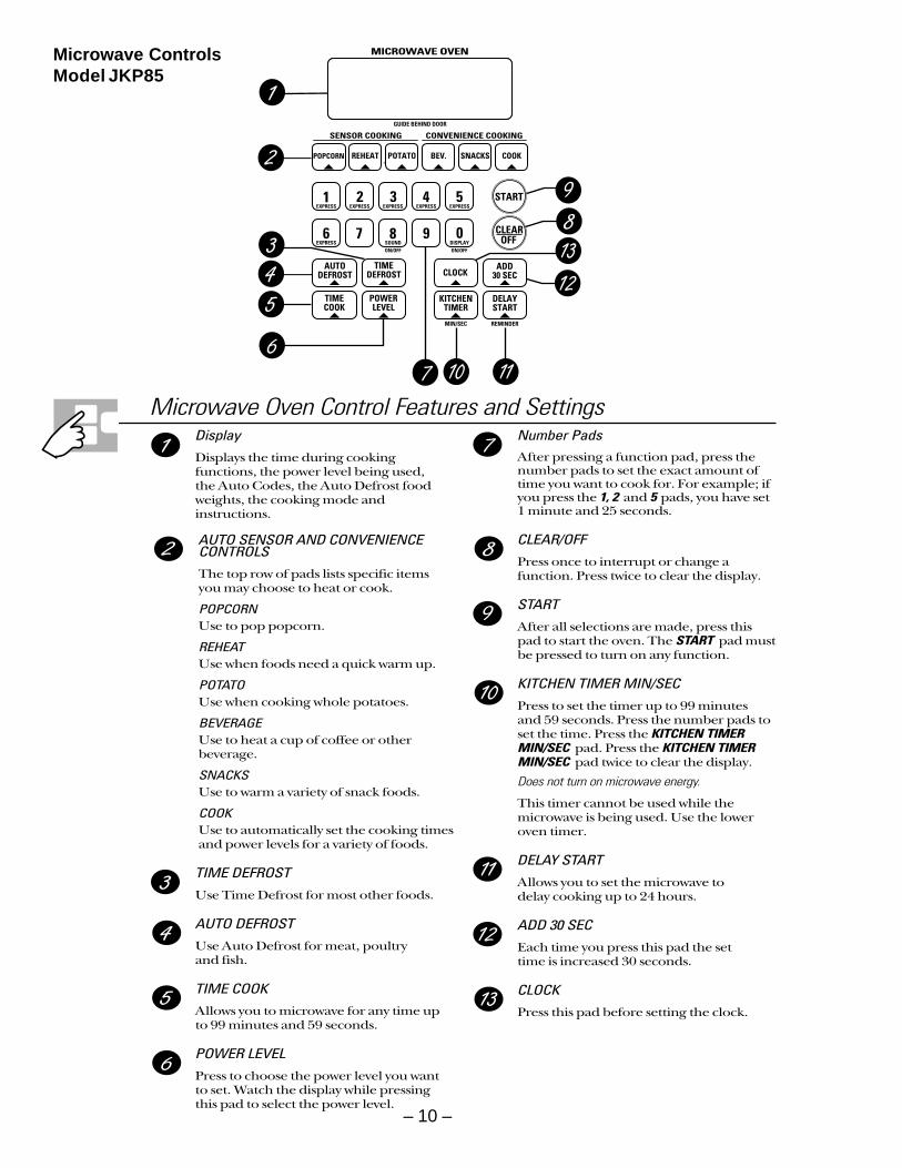
Microwave Oven Control Features and SettingsDisplayDisplays the time during cookingfunctions, the power level being used, the Auto Codes, the Auto Defrost foodweights, the cooking mode andinstructions.
AUTO SENSOR AND CONVENIENCECONTROLSThe top row of pads lists specific itemsyou may choose to heat or cook.
POPCORNUse to pop popcorn.
REHEATUse when foods need a quick warm up.
POTATOUse when cooking whole potatoes.
BEVERAGEUse to heat a cup of coffee or otherbeverage.
SNACKSUse to warm a variety of snack foods.
COOKUse to automatically set the cooking timesand power levels for a variety of foods.
TIME DEFROSTUse Time Defrost for most other foods.
AUTO DEFROSTUse Auto Defrost for meat, poultry and fish.
TIME COOKAllows you to microwave for any time upto 99 minutes and 59 seconds.
POWER LEVELPress to choose the power level you wantto set. Watch the display while pressingthis pad to select the power level.
Number PadsAfter pressing a function pad, press thenumber pads to set the exact amount oftime you want to cook for. For example; ifyou press the 1, 2 and 5 pads, you have set1 minute and 25 seconds.
CLEAR/OFFPress once to interrupt or change afunction. Press twice to clear the display.
STARTAfter all selections are made, press thispad to start the oven. The START pad mustbe pressed to turn on any function.
KITCHEN TIMER MIN/SECPress to set the timer up to 99 minutes and 59 seconds. Press the number pads toset the time. Press the KITCHEN TIMERMIN/SEC pad. Press the KITCHEN TIMERMIN/SEC pad twice to clear the display.
Does not turn on microwave energy.
This timer cannot be used while themicrowave is being used. Use the loweroven timer.
DELAY STARTAllows you to set the microwave to delay cooking up to 24 hours.
ADD 30 SECEach time you press this pad the set time is increased 30 seconds.
CLOCKPress this pad before setting the clock.
Microwave ControlsModel JKP85
– 11 –
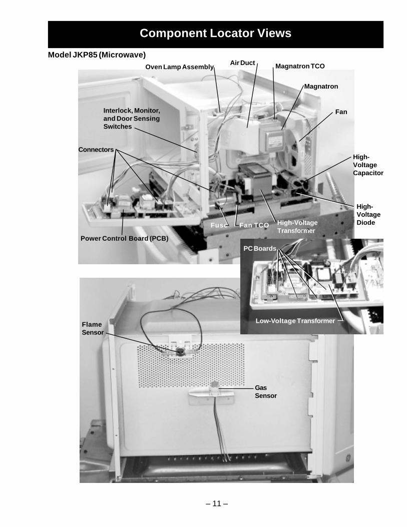
Component Locator Views
Model JKP85 (Microwave)Magnatron TCO
High-VoltageCapacitor
Fan
Magnatron
Oven Lamp Assembly
Interlock, Monitor,and Door SensingSwitches
Power Control Board (PCB)
PC Boards
Connectors
Fuse Fan TCO
GasSensor
FlameSensor
Low-Voltage Transformer
High-VoltageDiodeHigh-Voltage
Transformer
Air Duct
– 12 –
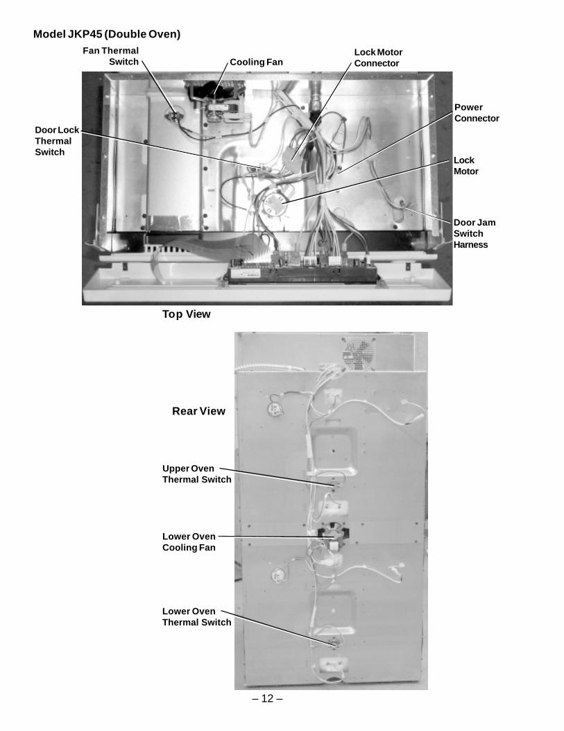
Model JKP45 (Double Oven)
Cooling Fan
Door JamSwitchHarness
Top View
LockMotor
Door LockThermalSwitch
Fan ThermalSwitch
Lock MotorConnector
PowerConnector
Rear View
Upper OvenThermal Switch
Lower OvenThermal Switch
Lower OvenCooling Fan
– 13 –
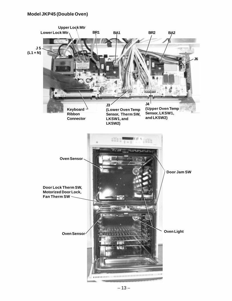
Model JKP45 (Double Oven)
KeyboardRibbonConnector
J 5(L1 + N)
Lower Lock Mtr
Oven Sensor
Oven Sensor
Door Jam SW
BR2Upper Lock Mtr
BA1BR1 BA2
J6
J4(Upper Oven TempSensor, LKSW1,and LKSW2)
J3(Lower Oven TempSensor, Therm SW,LKSW1, andLKSW2)
Door Lock Therm SW,Motorized Door Lock,Fan Therm SW
Oven Light
– 14 –
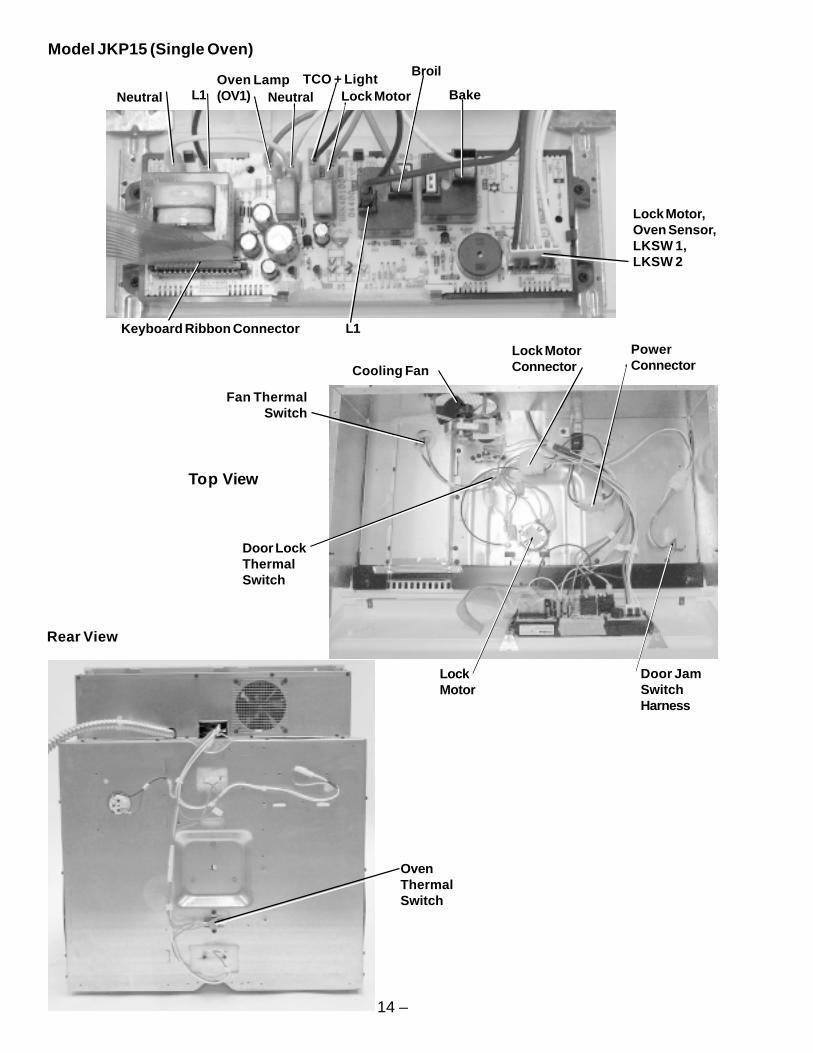
Model JKP15 (Single Oven)
Rear View
OvenThermalSwitch
Cooling Fan
Door JamSwitchHarness
Top View
LockMotor
Door LockThermalSwitch
Fan ThermalSwitch
Lock MotorConnector
PowerConnector
NeutralOven Lamp(OV1)L1 Neutral
L1
TCO + LightBakeLock Motor
Broil
Lock Motor,Oven Sensor,LKSW 1,LKSW 2
Keyboard Ribbon Connector
– 15 –
Oven
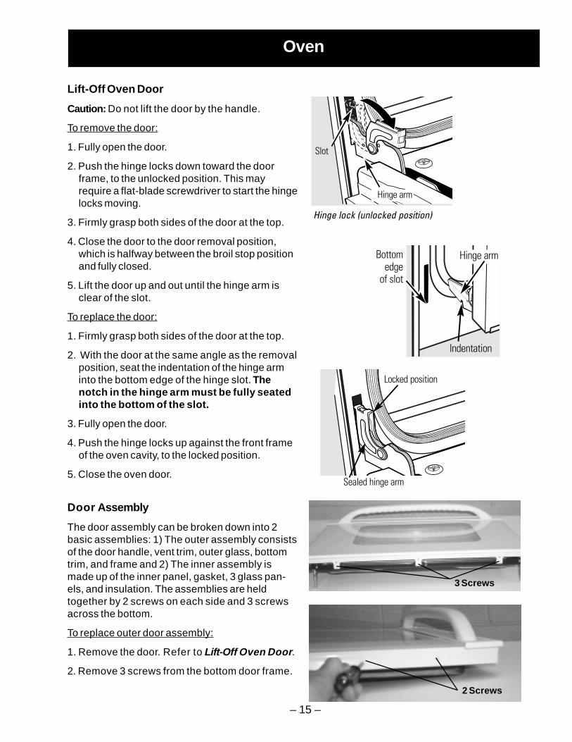
Lift-Off Oven Door
Caution: Do not lift the door by the handle.
To remove the door:
1. Fully open the door.
2. Push the hinge locks down toward the doorframe, to the unlocked position. This mayrequire a flat-blade screwdriver to start the hingelocks moving.
3. Firmly grasp both sides of the door at the top.
4. Close the door to the door removal position,which is halfway between the broil stop positionand fully closed.
5. Lift the door up and out until the hinge arm isclear of the slot.
To replace the door:
1. Firmly grasp both sides of the door at the top.
2. With the door at the same angle as the removalposition, seat the indentation of the hinge arminto the bottom edge of the hinge slot. Thenotch in the hinge arm must be fully seatedinto the bottom of the slot.
3. Fully open the door.
4. Push the hinge locks up against the front frameof the oven cavity, to the locked position.
5. Close the oven door.
Door Assembly
The door assembly can be broken down into 2basic assemblies: 1) The outer assembly consistsof the door handle, vent trim, outer glass, bottomtrim, and frame and 2) The inner assembly ismade up of the inner panel, gasket, 3 glass pan-els, and insulation. The assemblies are heldtogether by 2 screws on each side and 3 screwsacross the bottom.
To replace outer door assembly:
1. Remove the door. Refer to Lift-Off Oven Door.
2. Remove 3 screws from the bottom door frame.
Hinge lock (unlocked position)
Slot
Hinge arm
hef theo the
f the
Hinge arm
Indentation
Bottomedge
of slot
Locked position
Sealed hinge arm
3 Screws
2 Screws
– 16 –
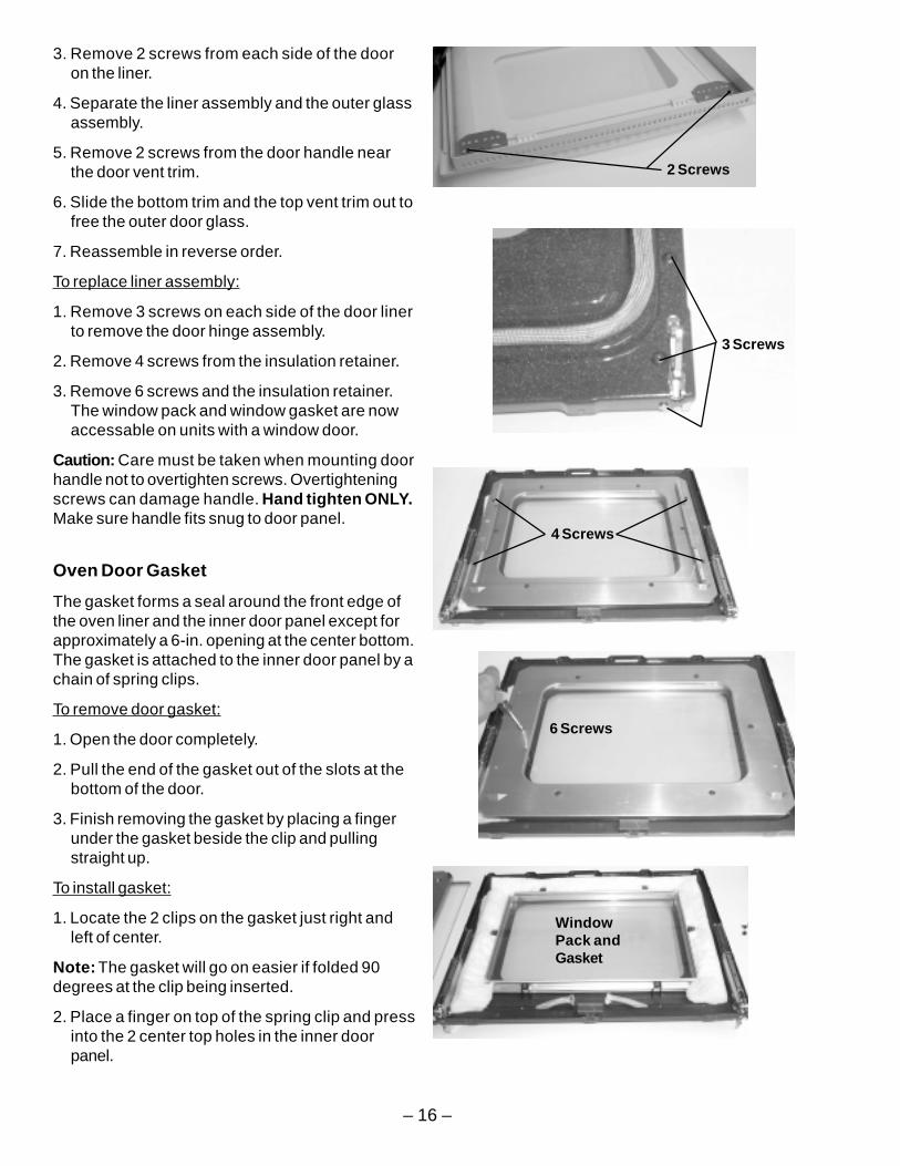
3. Remove 2 screws from each side of the dooron the liner.
4. Separate the liner assembly and the outer glassassembly.
5. Remove 2 screws from the door handle nearthe door vent trim.
6. Slide the bottom trim and the top vent trim out tofree the outer door glass.
7. Reassemble in reverse order.
To replace liner assembly:
1. Remove 3 screws on each side of the door linerto remove the door hinge assembly.
2. Remove 4 screws from the insulation retainer.
3. Remove 6 screws and the insulation retainer.The window pack and window gasket are nowaccessable on units with a window door.
Caution: Care must be taken when mounting doorhandle not to overtighten screws. Overtighteningscrews can damage handle. Hand tighten ONLY.Make sure handle fits snug to door panel.
Oven Door Gasket
The gasket forms a seal around the front edge ofthe oven liner and the inner door panel except forapproximately a 6-in. opening at the center bottom.The gasket is attached to the inner door panel by achain of spring clips.
To remove door gasket:
1. Open the door completely.
2. Pull the end of the gasket out of the slots at thebottom of the door.
3. Finish removing the gasket by placing a fingerunder the gasket beside the clip and pullingstraight up.
To install gasket:
1. Locate the 2 clips on the gasket just right andleft of center.
Note: The gasket will go on easier if folded 90degrees at the clip being inserted.
2. Place a finger on top of the spring clip and pressinto the 2 center top holes in the inner doorpanel.
2 Screws
WindowPack andGasket
6 Screws
4 Screws
3 Screws
– 17 –
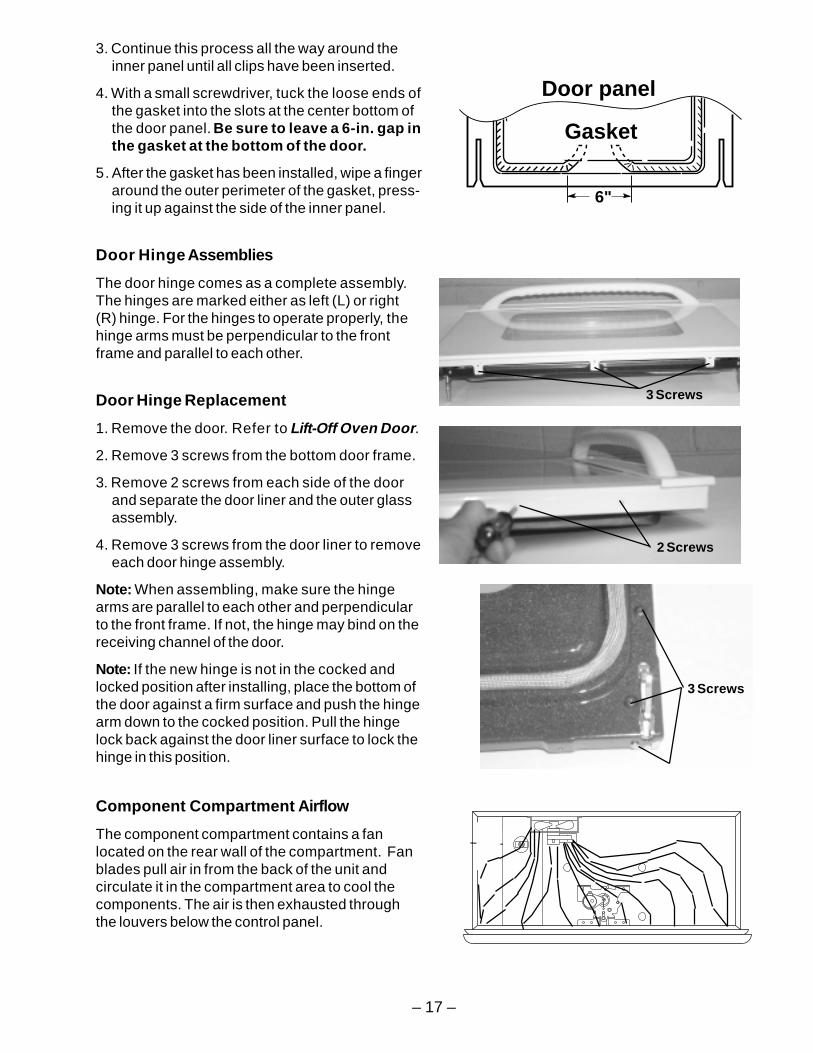
3. Continue this process all the way around theinner panel until all clips have been inserted.
4. With a small screwdriver, tuck the loose ends ofthe gasket into the slots at the center bottom ofthe door panel. Be sure to leave a 6-in. gap inthe gasket at the bottom of the door.
5. After the gasket has been installed, wipe a fingeraround the outer perimeter of the gasket, press-ing it up against the side of the inner panel.
Door Hinge Assemblies
The door hinge comes as a complete assembly.The hinges are marked either as left (L) or right(R) hinge. For the hinges to operate properly, thehinge arms must be perpendicular to the frontframe and parallel to each other.
Door Hinge Replacement
1. Remove the door. Refer to Lift-Off Oven Door.
2. Remove 3 screws from the bottom door frame.
3. Remove 2 screws from each side of the doorand separate the door liner and the outer glassassembly.
4. Remove 3 screws from the door liner to removeeach door hinge assembly.
Note: When assembling, make sure the hingearms are parallel to each other and perpendicularto the front frame. If not, the hinge may bind on thereceiving channel of the door.
Note: If the new hinge is not in the cocked andlocked position after installing, place the bottom ofthe door against a firm surface and push the hingearm down to the cocked position. Pull the hingelock back against the door liner surface to lock thehinge in this position.
6"
Door panel
Gasket
3 Screws
Component Compartment Airflow
The component compartment contains a fanlocated on the rear wall of the compartment. Fanblades pull air in from the back of the unit andcirculate it in the compartment area to cool thecomponents. The air is then exhausted throughthe louvers below the control panel.
2 Screws
3 Screws
– 18 –
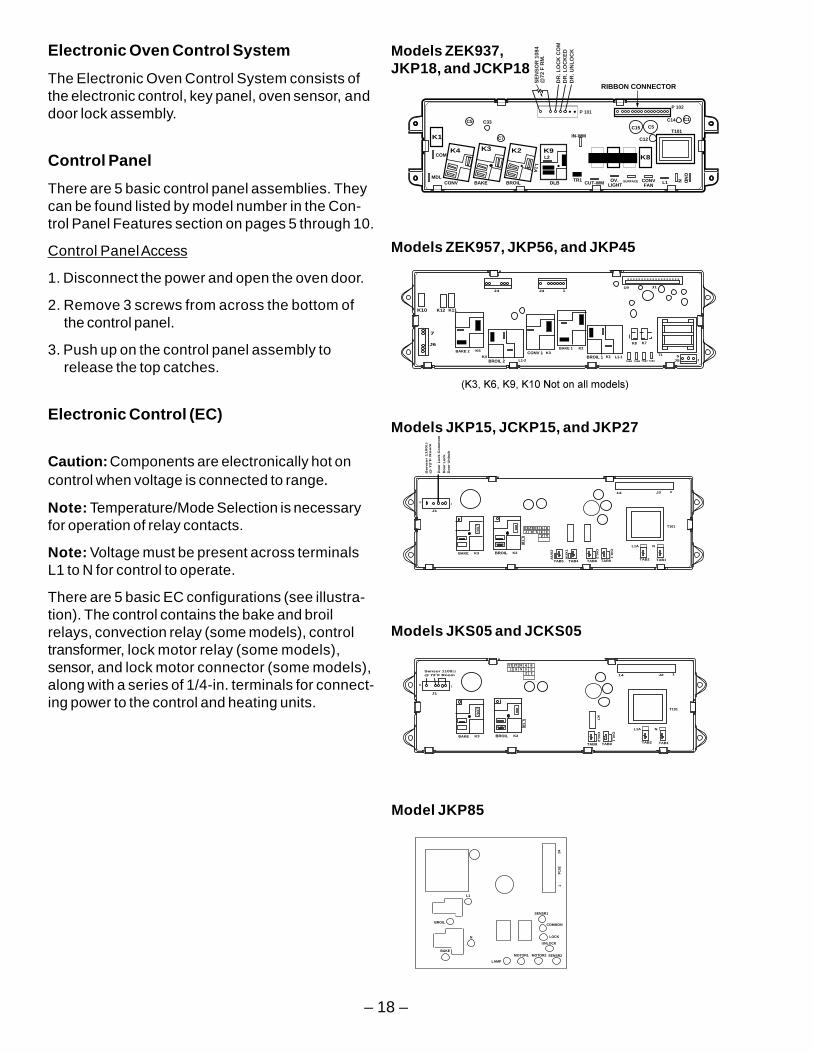
Electronic Oven Control System
The Electronic Oven Control System consists ofthe electronic control, key panel, oven sensor, anddoor lock assembly.
Control Panel
There are 5 basic control panel assemblies. Theycan be found listed by model number in the Con-trol Panel Features section on pages 5 through 10.
Control Panel Access
1. Disconnect the power and open the oven door.
2. Remove 3 screws from across the bottom ofthe control panel.
3. Push up on the control panel assembly torelease the top catches.
Electronic Control (EC)
Caution: Components are electronically hot oncontrol when voltage is connected to range.
Note: Temperature/Mode Selection is necessaryfor operation of relay contacts.
Note: Voltage must be present across terminalsL1 to N for control to operate.
There are 5 basic EC configurations (see illustra-tion). The control contains the bake and broilrelays, convection relay (some models), controltransformer, lock motor relay (some models),sensor, and lock motor connector (some models),along with a series of 1/4-in. terminals for connect-ing power to the control and heating units.
SE
NS
OR
108
4
@72
F R
M.
DR
. LO
CK
CO
MD
R. L
OC
KE
DD
R. U
NL
OC
K
RIBBON CONNECTOR
P 101
MDLBROIL DLB
L1A
CONV
COM
CONVFANBAKE
K1
K8K7
OV. LIGHT L1
NG
ND
K4 K3 K2 K9
C5 C33
C7
L2
TR1CUT-WM SURFACE
T101C5C15
C12
C14 C1
P 102
K6K5
IN-WM
D/>&/=&/<&/+*'" E
BAKE 2
K11
J4
K10
J6
7
K12
K5
BROIL 2K4
L1-2
CONV 1 K3BAKE 1 K2
BROIL 1 K1 L1-1
J3 1
...................19 J1
TAB4 TAB3 TAB2 TAB1
K8 K7
T1
J55
I
Models ZEK937,JKP18, and JCKP18
Models ZEK957, JKP56, and JKP45
Models JKS05 and JCKS05
L1
BROIL
N
BAKE
1
P10
2
14
SENSR1
COMMON
LOCK
UNLOCK
LAMP
MOTOR1 MOTOR2 SENSR2
Model JKP85
BAKE
J1
K3 BROIL K2
14
T101
Sen
so
r 1
100
Ω@
72˚F
Ro
om
19
L1
B
1234567
13 12 10 9 8
TAB8
OV
L2
TAB9
OV
L1
1J2
TAB2 TAB1
L1A N
Do
or
Lo
ck
Co
mm
om
Do
or
Lo
ck
Do
or
Un
loc
k
TAB5 TAB4
AU
X1
AU
X2
Models JKP15, JCKP15, and JKP27
BAKE
J1
K3 BROIL K2
14
T101
Sensor 1100Ω@ 72˚F Room
16
L1
B
1234567
13 12 10 9 8
TAB8
OV
L2
TAB9
OV
L1
K7
1J2
TAB2 TAB1
L1A N
– 19 –
Key Panel Test
The key panel is connected to the control by aribbon connector. The control will sound a tonewhen any of the pads are depressed except for the+/- pads.
To help isolate a problem to either the control orkey panel, depress each pad on the key panelfollowed by the Clear / Off pad and observe thefollowing:
• Bake, Broil, Clean, Timer, Clock, Stop Time,and Cook Time Modes - Audible tone plusdisplay showing mode of operation selected.
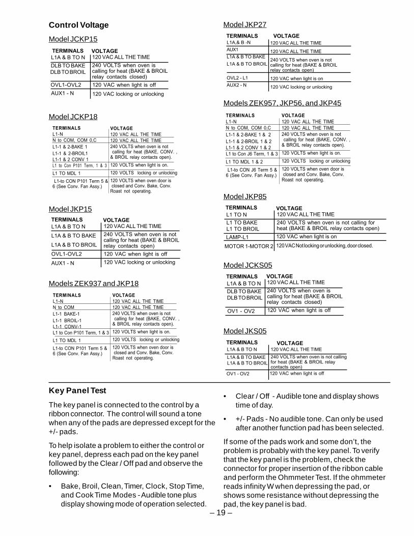
Control Voltage
• Clear / Off - Audible tone and display showstime of day.
• +/- Pads - No audible tone. Can only be usedafter another function pad has been selected.
If some of the pads work and some don’t, theproblem is probably with the key panel. To verifythat the key panel is the problem, check theconnector for proper insertion of the ribbon cableand perform the Ohmmeter Test. If the ohmmeterreads infinity W when depressing the pad, orshows some resistance without depressing thepad, the key panel is bad.
TERMINALS
L1A & B TO NVOLTAGE120 VAC ALL THE TIME
240 VOLTS when oven iscalling for heat (BAKE & BROILrelay contacts closed)
DLB TO BAKE
DLB TO BROIL
120 VAC when light is off
120 VAC locking or unlockingAUX1 - N
OVL1-OVL2
Model JCKP15
Model JCKP18TERMINALS
L1-N
N to COM, COM 0,C
L1-1 & 2-BAKE 1
L1-1 & 2-BROIL1
L1-1 & 2 CONV 1
L1 to Con P101 Term, 1 & 3
L1 TO MDL 1
L1-to CON P101 Term 5 &6 (See Conv. Fan Assy.)
VOLTAGE
120 VAC ALL THE TIME
120 VAC ALL THE TIME
240 VOLTS when oven is not calling for heat (BAKE, CONV. ,& BROIL relay contacts open).
120 VOLTS when light is on.
120 VOLTS locking or unlocking
120 VOLTS when oven door is closed and Conv. Bake, Conv.Roast not operating.
Model JCKS05TERMINALS
L1A & B TO N
DLB TO BAKEDLB TO BROIL
VOLTAGE120 VAC ALL THE TIME
240 VOLTS when oven iscalling for heat (BAKE & BROILrelay contacts closed)
120 VAC when light is offOV1 - OV2
Model JKP15TERMINALS
L1A & B TO N
L1A & B TO BAKE
L1A & B TO BROIL
OVL1-OVL2
AUX1 - N
VOLTAGE120 VAC ALL THE TIME
240 VOLTS when oven is notcalling for heat (BAKE & BROILrelay contacts open)
120 VAC when light is off
120 VAC locking or unlocking
Models ZEK937 and JKP18
TERMINALS
L1-N
N to COM
L1-1 BAKE-1
L1-1 BROIL-1
L1-1 CONV-1
L1 to Con P101 Term, 1 & 3
L1 TO MDL 1
L1-to CON P101 Term 5 &6 (See Conv. Fan Assy.)
VOLTAGE
120 VAC ALL THE TIME
120 VAC ALL THE TIME
240 VOLTS when oven is not calling for heat (BAKE, CONV. ,& BROIL relay contacts open).
120 VOLTS when light is on.
120 VOLTS locking or unlocking
120 VOLTS when oven door is closed and Conv. Bake, Conv.Roast not operating.
Model JKP27
L1A,& B -N
AUX1
L1A & B TO BAKE
L1A & B TO BROIL
OVL2 - L1
AUX2 - N
TERMINALS VOLTAGE
120 VAC ALL THE TIME
120 VAC ALL THE TIME
240 VOLTS when oven is notcalling for heat (BAKE & BROILrelay contacts open)
120 VAC when light is on
120 VAC locking or unlocking
Models ZEK957, JKP56, and JKP45
TERMINALS
L1-N
N to COM, COM 0,C
L1-1 & 2-BAKE 1 & 2
L1-1 & 2-BROIL 1 & 2
L1-1 & 2 CONV 1 & 2
L1 to Con J6 Term, 1 & 3
L1 TO MDL 1 & 2
L1-to CON J6 Term 5 &6 (See Conv. Fan Assy.)
VOLTAGE
120 VAC ALL THE TIME
120 VAC ALL THE TIME
240 VOLTS when oven is not calling for heat (BAKE, CONV. ,& BROIL relay contacts open).
120 VOLTS when light is on.
120 VOLTS locking or unlocking
120 VOLTS when oven door is closed and Conv. Bake, Conv.Roast not operating.
Model JKP85TERMINALS
L1 TO NVOLTAGE120 VAC ALL THE TIME
240 VOLTS when oven is not calling forheat (BAKE & BROIL relay contacts open)
L1 TO BAKEL1 TO BROIL
120 VAC when light is on
120 VAC Not locking or unlocking, door closed.
LAMP-L1
MOTOR 1-MOTOR 2
Model JKS05
TERMINALS
L1A & B TO N
L1A & B TO BAKE
L1A & B TO BROIL
VOLTAGE120 VAC ALL THE TIME
240 VOLTS when oven is not callingfor heat (BAKE & BROIL relaycontacts open)
120 VAC when light is offOV1 - OV2
– 20 –
Function
Bake
Broil
Oven Light
Cooking Time
Delay Start Time
Kitchen Timer
Clock
Clear/Off
Pins
11 to 13
10 to 13
11 to 14
12 to 10
11 ro 12
9 to 13
9 to 12
3 to 4
touch pads come as part. 1 to 2
14 to 9
8 to 14
5to 13
5 to 12
6 to 13
6 to 12
7 to 14
7 to 12
7 to 13
10 to 14
Start
1
2
3
4
5
6
7
8
9
0
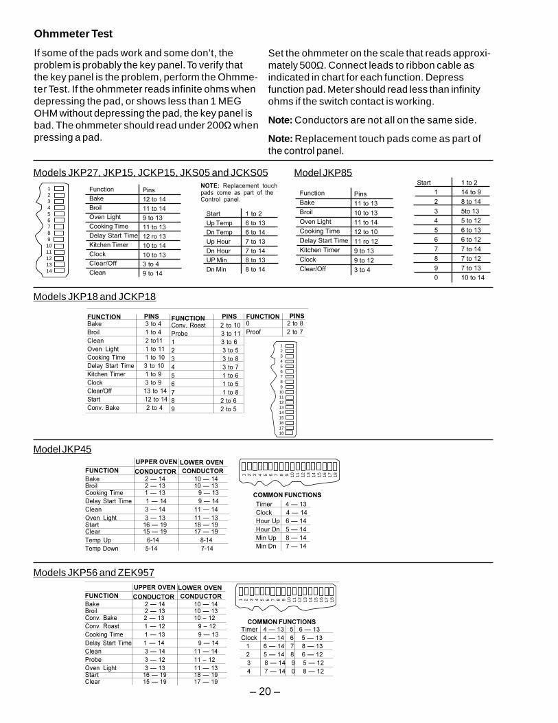
Ohmmeter Test
If some of the pads work and some don’t, theproblem is probably the key panel. To verify thatthe key panel is the problem, perform the Ohmme-ter Test. If the ohmmeter reads infinite ohms whendepressing the pad, or shows less than 1 MEGOHM without depressing the pad, the key panel isbad. The ohmmeter should read under 200Ω whenpressing a pad.
Set the ohmmeter on the scale that reads approxi-mately 500Ω. Connect leads to ribbon cable asindicated in chart for each function. Depressfunction pad. Meter should read less than infinityohms if the switch contact is working.
Note: Conductors are not all on the same side.
Note: Replacement touch pads come as part ofthe control panel.
1 to 2
6 to 13
6 to 14
7 to 13
7 to 14
8 to 13
8 to 14
Start
Up Temp
Dn Temp
Up Hour
Dn Hour
UP Min
Dn Min
NOTE: Replacement touchpads come as part of theControl panel.
Function
Bake
Broil
Oven Light
Cooking Time
Delay Start Time
Kitchen Timer
Clock
Clear/Off
Clean
Pins
12 to 14
11 to 14
9 to 13
11 to 13
12 ro 13
10 to 14
10 to 13
3 to 4
9 to 14
1234567891011121314
Models JKP27, JKP15, JCKP15, JKS05 and JCKS05
Model JKP45
Model JKP85
FUNCTION
Bake 2 — 14 10 — 14Broil 2 — 13 10 — 13Cooking Time 1 — 13 9 — 13
Delay Start Time 1 — 14 9 — 14
Clean 3 — 14 11 — 14
Oven Light 3 — 13 11 — 13Start 16 — 19 18 — 19Clear 15 — 19 17 — 19
Temp Up 6-14 8-14
Temp Down 5-14 7-14
UPPER OVEN
CONDUCTOR CONDUCTOR
COMMON FUNCTIONS
Timer 4 — 13
Clock 4 — 14
Hour Up 6 — 14
Hour Dn 5 — 14
Min Up 8 — 14
Min Dn 7 — 14
LOWER OVEN
1 2 3 4 5 6 7 8 9 10 11 12 13 14 15 16 17 18
!"#$ % %!&'() % %'*+!"#$ % ,'*+'"-. % ,''#(*/($% %0$)"1."&.($ % %)$"* % %2&'3$ % ,+$* (/4. % %."&. % % )$"& % %
($&%%)'5#%%%%%%
% %%%
1 2 3 4 5 6 7 8 9 10 11 12 13 14 15 16 17 18
Models JKP56 and ZEK957
Models JKP18 and JCKP18
FUNCTIONBake 3 to 4
Broil 1 to 4
Clean 2 to11
Oven Light 1 to 11
Cooking Time 1 to 10
Delay Start Time 3 to 10
Kitchen Timer 1 to 9
Clock 3 to 9
Clear/Off 13 to 14
Start 12 to 14
Conv. Bake 2 to 4
PINS
NOTE: Conductors are on eitherside but not both, Pin numbers areshown on control.
123456789
101112131415161718
FUNCTIONConv. Roast 2 to 10
Probe 3 to 11
1 3 to 6
2 3 to 5
3 3 to 8
4 3 to 7
5 1 to 6
6 1 to 5
7 1 to 8
8 2 to 6
9 2 to 5
FUNCTION0 2 to 8
Proof 2 to 7
PINS PINS
– 21 –
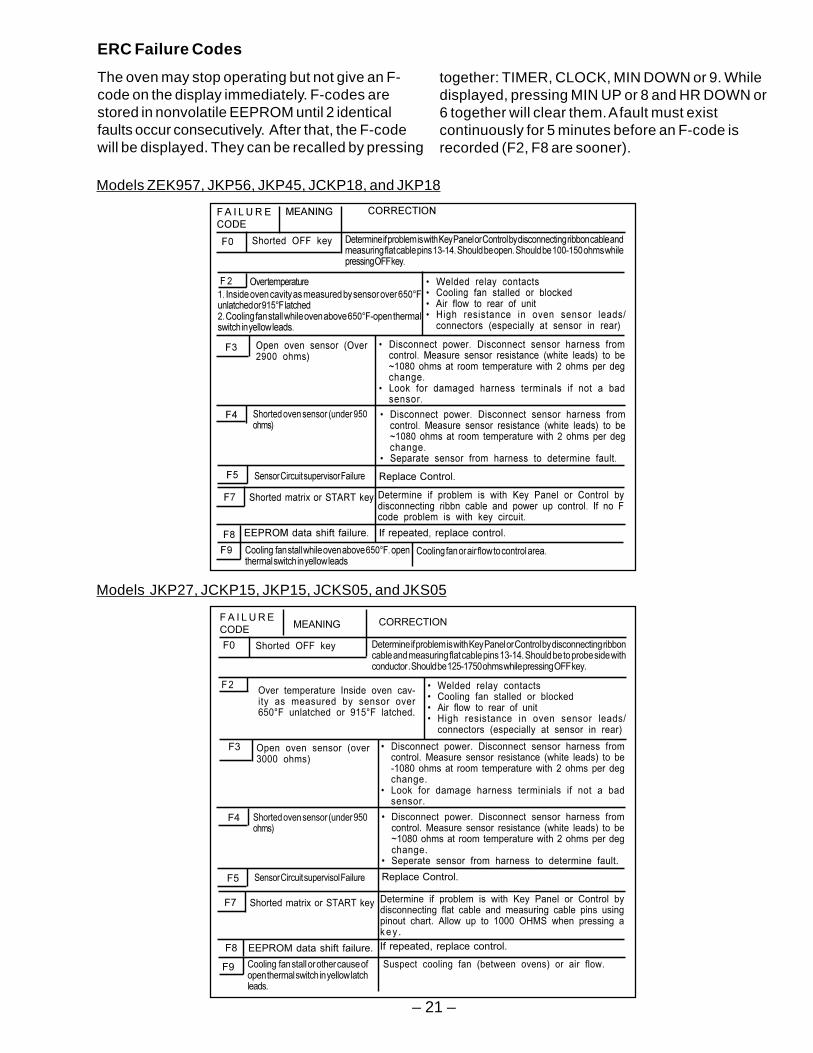
ERC Failure Codes
The oven may stop operating but not give an F-code on the display immediately. F-codes arestored in nonvolatile EEPROM until 2 identicalfaults occur consecutively. After that, the F-codewill be displayed. They can be recalled by pressing
together: TIMER, CLOCK, MIN DOWN or 9. Whiledisplayed, pressing MIN UP or 8 and HR DOWN or6 together will clear them. A fault must existcontinuously for 5 minutes before an F-code isrecorded (F2, F8 are sooner).
0
! "##$
# % & ' & $& ( & ) * + , -
"## $
"*
& . , - / 0 %
& 1$
" * ,"*%2 -
*,2! -
& . , - / 0 %
&
34(54$ 6 # $
29"."-4(:. :"()7&$ :&$$".$9>&$)"5$5'*.&')
**7! 8#
6***7! 8# 2!8# % **7! 8#
*# $)"5$'*.&')
Models ZEK957, JKP56, JKP45, JCKP18, and JKP18
F A I L U R E
CODE
Determine if problem is with Key Panel or Control by disconnecting ribboncable and measuring flat cable pins 13-14. Should be to probe side withconductor . Should be 125-1750 ohms while pressing OFF key.
F 2 • Welded relay contacts• Cooling fan stalled or blocked• Air flow to rear of unit• High resistance in oven sensor leads/
connectors (especially at sensor in rear)
Shorted OFF keyF0
Over temperature Inside oven cav-ity as measured by sensor over650°F unlatched or 915°F latched.
F3 • Disconnect power. Disconnect sensor harness fromcontrol. Measure sensor resistance (white leads) to be-1080 ohms at room temperature with 2 ohms per degchange.
• Look for damage harness terminials if not a badsensor.
Open oven sensor (over3000 ohms)
Shorted oven sensor (under 950ohms)
F4 • Disconnect power. Disconnect sensor harness fromcontrol. Measure sensor resistance (white leads) to be~1080 ohms at room temperature with 2 ohms per degchange.
• Seperate sensor from harness to determine fault.
Shorted matrix or START keyF7 Determine if problem is with Key Panel or Control bydisconnecting flat cable and measuring cable pins usingpinout chart. Allow up to 1000 OHMS when pressing ak e y .
F8 EEPROM data shift failure. If repeated, replace control.
F9 Cooling fan stall or other cause ofopen thermal switch in yellow latchleads.
Suspect cooling fan (between ovens) or air flow.
CORRECTIONMEANING
Sensor Circuit supervisol FailureF5 Replace Control.
Models JKP27, JCKP15, JKP15, JCKS05, and JKS05
– 22 –
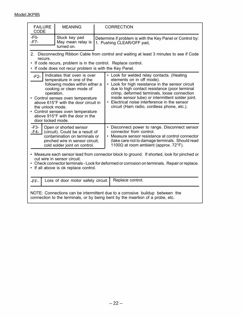
2. Disconnecting Ribbon Cable from control and waiting at least 3 minutes to see if Coderecurs.
• If code recurs, problem is in the control. Replace control.
• If code does not recur problem is with the Key Panel.
FAILURE MEANING CORRECTIONCODE
-F0--F7-
Stuck key padMay mean relay isturned on.
Determine if problem is with the Key Panel or Control by:1. Pushing CLEAR/OFF pad,
-F2- Indicates that oven is overtemperature in one of thefollowing modes within either acooking or clean mode ofoperation.
• Look for welded relay contacts. (Heatingelements on in off mode).
• Look for high resistance in the sensor circuitdue to high contact resistance (poor terminalcrimp, deformed terminals, loose connectioninside sensor tube) or intermittent solder joint.
• Electrical noise interference in the sensorcircuit (Ham radio, cordless phone, etc.).
• Control senses oven temperatureabove 615°F with the door circuit inthe unlock mode.
• Control senses oven temperatureabove 915°F with the door in thedoor locked mode.
Replace control.
• Disconnect power to range. Disconnect sensorconnector from control.
• Measure sensor resistance at control connector(take care not to damage terminals. Should read1100Ω at room ambient (approx. 72°F).
-F3--F4-
-FF- Loss of door motor safety circuit.
NOTE: Connections can be intermittent due to a corrosive buildup between theconnection to the terminals, or by being bent by the insertion of a probe, etc.
Open or shorted sensor(circuit). Could be a result ofcontamination on terminals orpinched wire in sensor circuit,cold solder joint on control.
• Measure each sensor lead from connector block to ground. If shorted, look for pinched orcut wire in sensor circuit.
• Check connector terminals - Look for deformed or corrosion on terminals. Repair or replace.• If all above is ok replace control.
Model JKP85
– 23 –
Special Functions
The control has a section that can be entered tochange how the control will work. To enter thissection, press and hold BAKE and BROIL padsfor 2 seconds. SF appears in the display. Selectthe area to change. When the change has beenmade, press START to return to Time of Day.
• End-of-Cycle Tone - Press TIMER pad.*Display shows Con Beep when control is setfor Continuous End-of-Cycle Tone or Beepwhen set for Noncontinuous.
• °F or °C - Press Broil pad. *Display will showeither F or C. Press Broil pad again tochange.
• 12 hour, 24 hour, or blank out Time of DayClock - Press Clock pad. *Display will show12 hr, 24 hr, OFF for blank clock. Press againto change.
• Cook & Hold (used only with Time Bake orDelay Bake functions) - Press Cooking Timepad. *Display will show either Hld On or HldOff. Press again to change.
• Child Lockout - Press CLEAN. *Display willshow Loc On (when any heating functions aretried, display will show Off). Press CLEANagain for Loc Off, control unlocked.
• 12-hour shutdown comes set to shut downafter 12 hours of continuous operations; thiscan be eliminated - Press Delay Start pad.*Display will show No Shdn. To turn back on,press Delay Start pad again and display willshow 12 Shdn.
Note: Sabbath is between No Shdn and 12 Shdn.
• Sales Mode (special feature added for salesfloor demonstration) - Press Clock and Timerpads at the same time. *Display will start tocycle through the different modes of operation.
• Sabbath Mode (GE models only) disables allbut bake, timebake, no beeps, and 12h shut-down override, and puts symbols on reddisplay during bake. Access by pressing DelayStart pad until display shows Sabbath. Exit bypressing Delay Start pad until No Shdn o r 12Shdn shows.
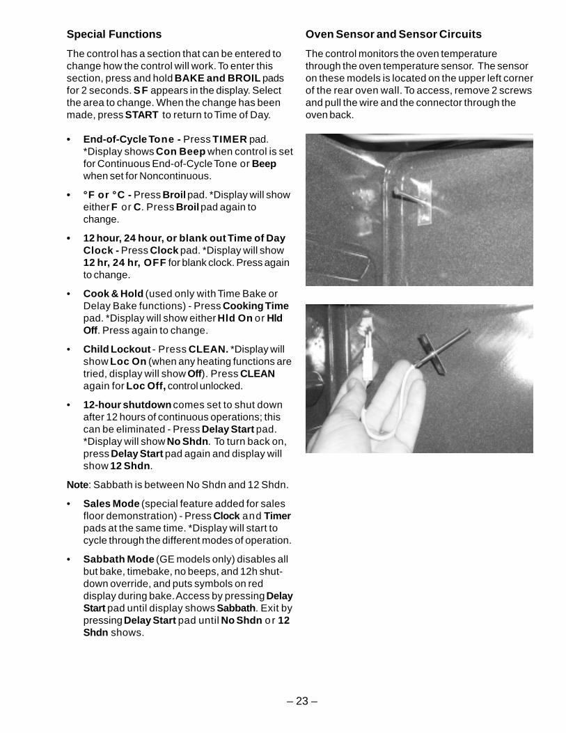
Oven Sensor and Sensor Circuits
The control monitors the oven temperaturethrough the oven temperature sensor. The sensoron these models is located on the upper left cornerof the rear oven wall. To access, remove 2 screwsand pull the wire and the connector through theoven back.
– 24 –
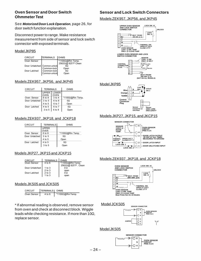
Sensor and Lock Switch Connectors
LOCK SW. #2
UNLOCK
LOCKSW. #1
OVEN SENSOR1100Ω @ RM. TEMP2582Ω @ CLEAN TEMPMeat Probe Not On All Models
THERMAL SW.OPEN AT 216 FCLOSE 177 F
12345678
BU O Y W
W
OVEN SENSOR AND LOCK SWITCH CONNECTOR
MEAT PROBE 30K-50K @m
Models ZEK937, JKP18, and JCKP18
1
2
3
4
6
SENSOR CONNECTOR
SENSOR 1100 @ROOMTEMP.
THERMALSWITCH
LOCK SW. 1
LOCK SW. 2
OVEN SENSORCIRCUITPINS 4 & 6
DOOR LATCH OUTPUT-25 VDC AT ALL TIMESMEASURED TO GROUND
DOOR LATCH INPUT
DOOR UNLATCHED INPUT
OPENS 216˚ FCLOSES 177˚ F
Models JKP27, JKP15, and JKCP15
LOCK SW. #2
UNLOCK
LOCKSW. #1
OVEN SENSOR1100 @ RM. TEMP2562 @ CLEAN TEMP
THERMAL SW.OPEN AT 216 FCLOSE 177 F
12345678
BU O Y W
W
3456789
10
SENSOR1100 @ RM2562 @ 825 F
CONTROLCONNECTORPLUG
LOWER OVEN SENSOR AND LOCK SWITCH CONNECTOR
LOCKSW1 LOCK
LOCKSW2 UNLOCK
UPPER OVEN SENSOR AND LOCK SWITCH CONNECTOR
MEAT PROBE 30K-50K @ rm
(NOT ON ALL MODELS)
MEAT PROBE 30K-50K @ rm
Models ZEK957, JKP56, and JKP45
9
87
BlueOrange
Yel/Blk
ControlConnectorPlug
LockSW. 1 Unlock
SW. 2
SensorConnector at Unit Rear
Sensor1000Ω @RM2562Ω@825˚F
Model JKP85
"L-1" 123
4
6
SENSOR CONNECTOR
OVEN SENSORCIRCUITPINS 4 & 6
5
JUMPER
Model JCKS05
4
6
SENSOR CONNECTOR
OVEN SENSORCIRCUITPINS 4 & 6
5
Model JKS05
* If abnormal reading is observed, remove sensorfrom oven and check at disconnect block. Wiggleleads while checking resistance. If more than 10Ω,replace sensor.
Models ZEK937, JKP18, and JCKP18
CIRCUIT TERMINALS OHMS
UPPER OVEN
Oven Sensor 6 to 8 *1100Ω@Rm Temp.
Door Unlatched 3 to 5 0Ω 4 to 5 Open
Door Latched 4 to 5 0Ω 3 to 5 Open
Models JKS05 and JCKS05
CIRCUIT TERMINALS OHMS
Oven Sensor 4 to 6 *1100Ω@Rm Temp.
Models JKP27, JKP15 and JCKP15
CIRCUIT TERMINALS OHMSOven Sensor 4 to 6 *1100Ω@Rm Temp.
2562Ω@ 825°F . CleanDoor Unlatched 1 to 3 0 Ω
2 to 3 openDoor Latched 2 to 3 0 Ω
1 to 3 open
Models ZEK957, JKP56, and JKP45
CIRCUIT TERMINALS OHMS
UPPER LOWER OVEN OVEN
Oven Sensor 6 to 8 3 to 4 *1100Ω@Rm Temp.
Door Unlatched 3 to 5 6 to 8 0Ω 4 to 5 6 to 7 Open
Door Latched 4 to 5 6 to 7 0Ω 3 to 5 6 to 8 Open
Model JKP85
CIRCUIT TERMINALS OHMS
Oven Sensor *1100Ω@Rm Temp. 2562Ω@ 825°F Clean
Door Unlatched Common-unlock 0Ω Common-lock Open
Door Latched Common-lock 0Ω Common-unlock Open
Oven Sensor and Door SwitchOhmmeter Test
See Motorized Door Lock Operation, page 26, fordoor switch function explanation.
Disconnect power to range. Make resistancemeasurement from side of sensor and lock switchconnector with exposed terminals.
– 25 –
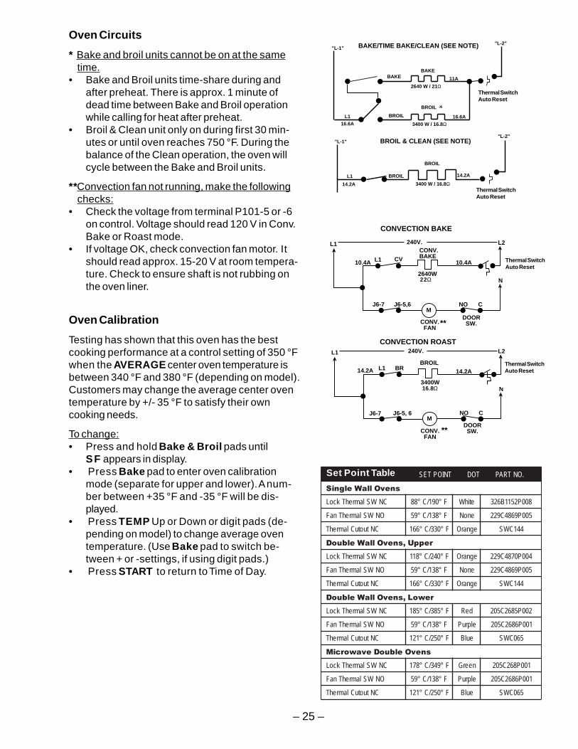
Oven Circuits
* Bake and broil units cannot be on at the sametime.
• Bake and Broil units time-share during andafter preheat. There is approx. 1 minute ofdead time between Bake and Broil operationwhile calling for heat after preheat.
• Broil & Clean unit only on during first 30 min-utes or until oven reaches 750 °F. During thebalance of the Clean operation, the oven willcycle between the Bake and Broil units.
**Convection fan not running, make the followingchecks:
• Check the voltage from terminal P101-5 or -6on control. Voltage should read 120 V in Conv.Bake or Roast mode.
• If voltage OK, check convection fan motor. Itshould read approx. 15-20 V at room tempera-ture. Check to ensure shaft is not rubbing onthe oven liner.
Oven Calibration
Testing has shown that this oven has the bestcooking performance at a control setting of 350 °Fwhen the AVERAGE center oven temperature isbetween 340 °F and 380 °F (depending on model).Customers may change the average center oventemperature by +/- 35 °F to satisfy their owncooking needs.
To change:• Press and hold Bake & Broil pads until
SF appears in display.• Press Bake pad to enter oven calibration
mode (separate for upper and lower). A num-ber between +35 °F and -35 °F will be dis-played.
• Press TEMP Up or Down or digit pads (de-pending on model) to change average oventemperature. (Use Bake pad to switch be-tween + or -settings, if using digit pads.)
• Press START to return to Time of Day.
.ONTRAPTODTNIOPTES
snevOllaWelgniS
CNWSlamrehTkcoL F°091/C°88 etihW 800P2511B623
ONWSlamrehTnaF F°831/C°95 enoN 500P9684C922
CNtuotuClamrehT F°033/C°661 egnarO 441CWS
reppU,snevOllaWelbuoD
CNWSlamrehTkcoL F°042/C°811 egnarO 400P0784C922
ONWSlamrehTnaF F°831/C°95 enoN 500P9684C922
CNtuotuClamrehT F°033/C°661 egnarO 441CWS
rewoL,snevOllaWelbuoD
CNWSlamrehTkcoL F°583/C°581 deR 200P5862C502
ONWSlamrehTnaF F°831/C°95 elpruP 100P6862C502
CNtuotuClamrehT F°052/C°121 eulB 560CWS
snevOelbuoDevaworciM
CNWSlamrehTkcoL F°943/C°871 neerG 100P862C502
ONWSlamrehTnaF F°831/C°95 elpruP 100P6862C502
CNtuotuClamrehT F°052/C°121 eulB 560CWS
Set Point Table
L2L1
N
L1
J6-7 J6-5,6M
CONV.BAKE
CONV. FAN
DOOR SW.
2640W 22W
CONVECTION BAKE
NO C
L2L1
N
L1
J6-7 J6-5, 6M
BROIL
CONV. FAN
DOOR SW.
3400W 16.8W
CONVECTION ROAST
NO C
240V.
240V.
10.4A 10.4A
14.2A 14.2A
CV
BR
**
**
(Lower Only)Thermal Switch 250˚ F auto Reset
(Lower Only)Thermal Switch 250˚ F auto Reset
BAKEBAKE
"L-1"
BROILL1
BROIL
"L-2"
"L-1"
L1 BROIL
BROIL
"L-2"
2640 W / 21Ω
3400 W / 16.8Ω
BAKE/TIME BAKE/CLEAN (SEE NOTE)
BROIL & CLEAN (SEE NOTE)
3400 W / 16.8Ω
11A
16.6A
14.2A
Thermal Switch300˚F ManualReset (Lower Only)
16.6A
14.2AThermal Switch300˚F ManualReset (Lower Only)
Thermal SwitchAuto Reset
Thermal SwitchAuto Reset
Thermal SwitchAuto Reset
22Ω
Thermal SwitchAuto Reset
16.8Ω
– 26 –
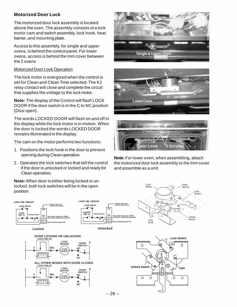
Lock Switch
CamUnlock SwitchL
LOCK RELAY
C MDL
LOCKMOTOR DOOR
SWITCHN
NC
CNO
ALL OTHER MODES WITH DOOR CLOSED
L
LOCK RELAY
C MDL
LOCKMOTOR DOOR
SWITCHN
NC
CNO
DOOR LOCKING OR UNLOCKING
543
Door latch output pin -25VDCat all times measured to ground
Door Unlatched Input Pin
Sensor and Lock Switch ConnectorsLOCK SW.#2
LOCKSW. #1
LOCK SW. CIRCUIT
Thermal Switch6
8
Locked
543
Door latch output pin -25VDCat all times measured to ground
Door Unlatched Input Pin
Sensor and Lock Switch ConnectorsLOCK SW.#2
UnlOCKSW. #1
LOCK SW. CIRCUIT
Thermal Switch6
8
Unlocked
Motorized Door Lock
The motorized door lock assembly is locatedabove the oven. The assembly consists of a lockmotor cam and switch assembly, lock hook, heatbarrier, and mounting plate.
Access to this assembly, for single and upperovens, is behind the control panel. For lowerovens, access is behind the trim cover betweenthe 2 ovens.
Motorized Door Lock Operation
The lock motor is energized when the control isset for Clean and Clean Time selected. The K1relay contact will close and complete the circuitthat supplies the voltage to the lock motor.
Note: The display of the Control will flash LOCKDOOR if the door switch is in the C to NC position(Door open).
The words LOCKED DOOR will flash on and off inthe display while the lock motor is in motion. Whenthe door is locked the words LOCKED DOORremains illuminated in the display.
The cam on the motor performs two functions:
1. Positions the lock hook in the door to preventopening during Clean operation.
2. Operates the lock switches that tell the controlif the door is unlocked or locked and ready forClean operation.
Note: When door is either being locked or un-locked, both lock switches will be in the openposition.
Note: For lower oven, when assembling, attachthe motorized door lock assembly to the trim coverand assemble as a unit.
MotorizedDoor Lock 2 Screws
Single & Upper Oven
Lower Oven
– 27 –
FanOn Device
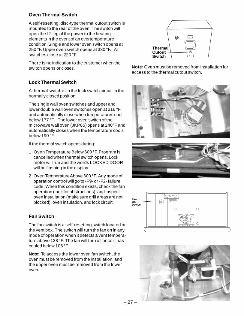
Oven Thermal Switch
A self-resetting, disc-type thermal cutout switch ismounted to the rear of the oven. The switch willopen the L2 leg of the power to the heatingelements in the event of an overtemperaturecondition. Single and lower oven switch opens at250 °F. Upper oven switch opens at 330 °F. Allswitches close at 220 °F.
There is no indication to the customer when theswitch opens or closes.
Lock Thermal Switch
A thermal switch is in the lock switch circuit in thenormally closed position.
The single wall oven switches and upper andlower double wall oven switches open at 216 °Fand automatically close when temperatures coolbelow 177 °F. The lower oven switch of themicrowave wall oven (JKP85) opens at 240°F andautomatically closes when the temperature coolsbelow 190 °F.
If the thermal switch opens during:
1. Oven Temperature Below 600 °F. Program iscancelled when thermal switch opens. Lockmotor will run and the words LOCKED DOORwill be flashing in the display.
2. Oven Temperature Above 600 °F. Any mode ofoperation control will go to -F9- or -F2- failurecode. When this condition exists, check the fanoperation (look for obstructions), and inspectoven installation (make sure grill areas are notblocked), oven insulation, and lock circuit.
Fan Switch
The fan switch is a self-resetting switch located onthe vent box. The switch will turn the fan on in anymode of operation when it detects a vent tempera-ture above 138 °F. The fan will turn off once it hascooled below 106 °F.
Note: To access the lower oven fan switch, theoven must be removed from the installation, andthe upper oven must be removed from the loweroven.
ThermalCutoutSwitch
Note: Oven must be removed from installation foraccess to the thermal cutout switch.
DoorLockThermalSwitch
DoorLockThermalSwitch
– 28 –
FANBLADE
OVENLINER
OVENINSULATION
OUTERBACK PANEL
CONV.FAN
(3)
SCREWS(4)
COLLARMTG.SHAFT
MOUNTINGSCREWS
(3)
LINER
CONV. FANMTG.SCREWS
FAN BLADENUT
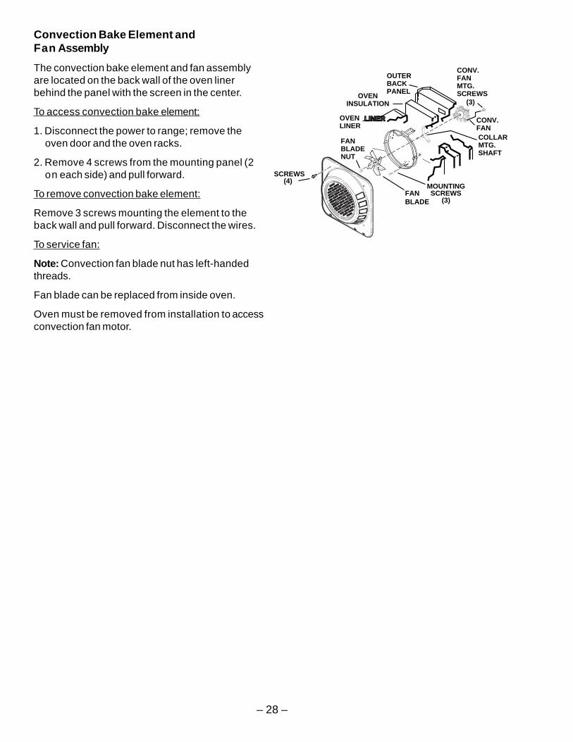
Convection Bake Element andFan Assembly
The convection bake element and fan assemblyare located on the back wall of the oven linerbehind the panel with the screen in the center.
To access convection bake element:
1. Disconnect the power to range; remove theoven door and the oven racks.
2. Remove 4 screws from the mounting panel (2on each side) and pull forward.
To remove convection bake element:
Remove 3 screws mounting the element to theback wall and pull forward. Disconnect the wires.
To service fan:
Note: Convection fan blade nut has left-handedthreads.
Fan blade can be replaced from inside oven.
Oven must be removed from installation to accessconvection fan motor.
– 29 –
Microwave
WARNING:DISCONNECT POWER BEFORE SERVICING.
Reconnect all grounding devices.
All parts of this appliance capable of conducting electrical current are grounded. If ground wires,screws, straps, clips, nuts, or washers used to complete a path to ground are removed for service,they must be returned to their original position and properly fastened.
Precautions to be observed before and during servicing to avoidpossible exposure to excessive microwave energy:
A . A microwave emissions check should be performed prior to servicing if oven is operative.
B. Do not operate or allow the oven to be operated with the door open.
C. If the oven operates with the door open:
1) Instruct the user not to operate the oven.
2) Contact the manufacturer and the center for devices and radiological health immediately.
D. Make the following safety checks on all ovens to be serviced before activating themagnetron or other microwave source. Make repairs as necessary.
1) Interlock operation
2) Proper door closing
3) Seal and sealing surfaces (arching, wear, and other damage)
4) Damage to and loosening of hinges and latches
5) Evidence of dropping or abuse
E. Before turning on microwave power for any test or inspection within the microwavegenerating compartments, check the magnetron, wave guide or transmission line, andcavity for proper alignment, integrity, and connections.
F. Any defective or misadjusted components in the interlock, monitor, door seal, and micro-wave generation and transmission systems shall be repaired, replaced, or adjusted byprocedure described in this manual before the oven is released to the owner.
G . A microwave leakage check to verify compliance with the federal performance standardshould be performed on each oven prior to release to the owner.
– 30 –
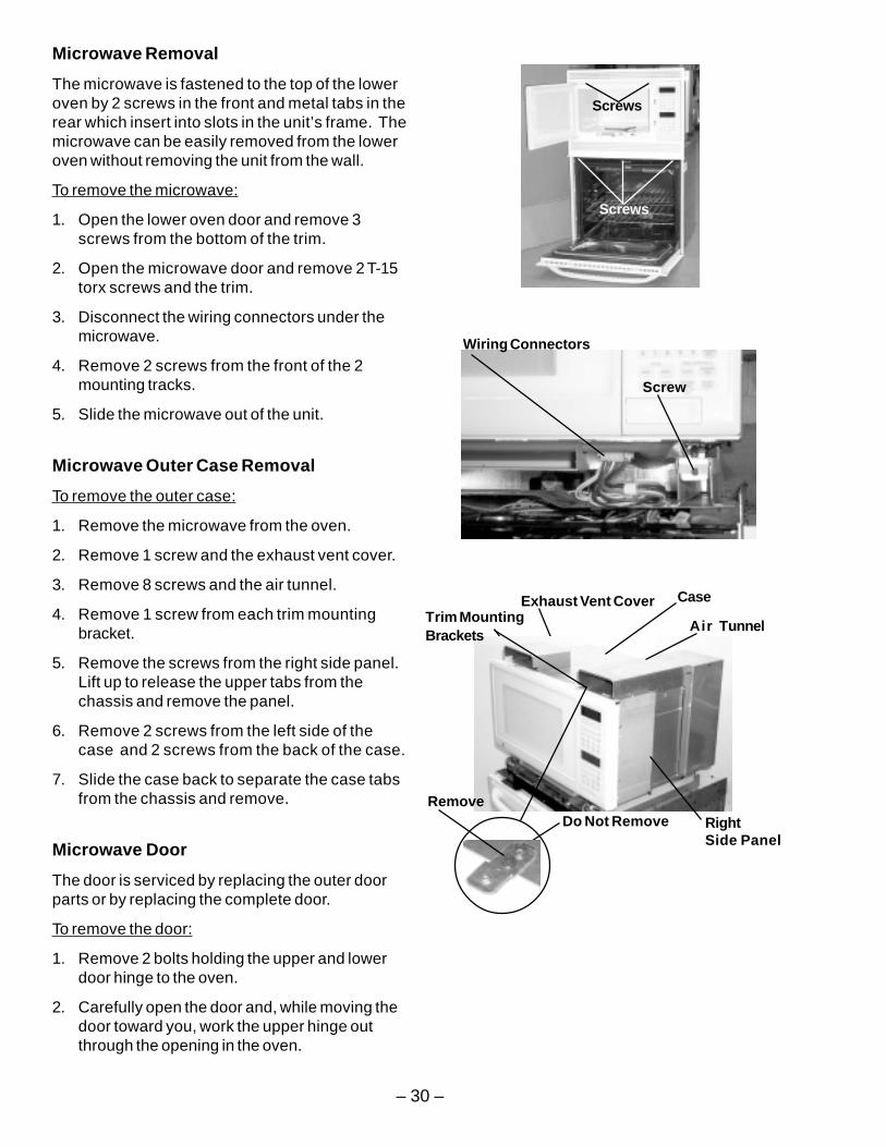
Microwave Removal
The microwave is fastened to the top of the loweroven by 2 screws in the front and metal tabs in therear which insert into slots in the unit’s frame. Themicrowave can be easily removed from the loweroven without removing the unit from the wall.
To remove the microwave:
1. Open the lower oven door and remove 3screws from the bottom of the trim.
2. Open the microwave door and remove 2 T-15torx screws and the trim.
3. Disconnect the wiring connectors under themicrowave.
4. Remove 2 screws from the front of the 2mounting tracks.
5. Slide the microwave out of the unit.
Microwave Outer Case Removal
To remove the outer case:
1. Remove the microwave from the oven.
2. Remove 1 screw and the exhaust vent cover.
3. Remove 8 screws and the air tunnel.
4. Remove 1 screw from each trim mountingbracket.
5. Remove the screws from the right side panel.Lift up to release the upper tabs from thechassis and remove the panel.
6. Remove 2 screws from the left side of thecase and 2 screws from the back of the case.
7. Slide the case back to separate the case tabsfrom the chassis and remove.
Microwave Door
The door is serviced by replacing the outer doorparts or by replacing the complete door.
To remove the door:
1. Remove 2 bolts holding the upper and lowerdoor hinge to the oven.
2. Carefully open the door and, while moving thedoor toward you, work the upper hinge outthrough the opening in the oven.
Exhaust Vent Cover
Air TunnelTrim MountingBrackets
RightSide Panel
Case
RemoveDo Not Remove
Wiring Connectors
Screw
Screws
Screws
– 31 –
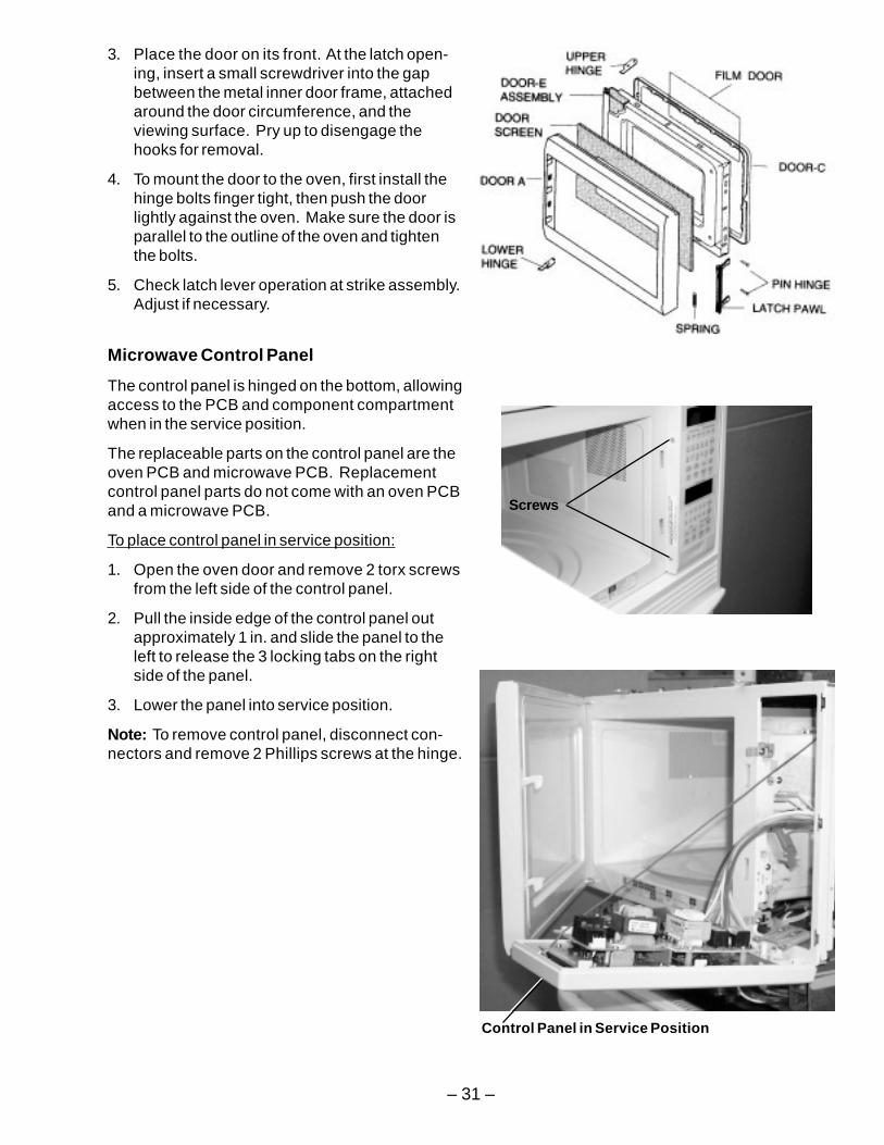
3. Place the door on its front. At the latch open-ing, insert a small screwdriver into the gapbetween the metal inner door frame, attachedaround the door circumference, and theviewing surface. Pry up to disengage thehooks for removal.
4. To mount the door to the oven, first install thehinge bolts finger tight, then push the doorlightly against the oven. Make sure the door isparallel to the outline of the oven and tightenthe bolts.
5. Check latch lever operation at strike assembly.Adjust if necessary.
Microwave Control Panel
The control panel is hinged on the bottom, allowingaccess to the PCB and component compartmentwhen in the service position.
The replaceable parts on the control panel are theoven PCB and microwave PCB. Replacementcontrol panel parts do not come with an oven PCBand a microwave PCB.
To place control panel in service position:
1. Open the oven door and remove 2 torx screwsfrom the left side of the control panel.
2. Pull the inside edge of the control panel outapproximately 1 in. and slide the panel to theleft to release the 3 locking tabs on the rightside of the panel.
3. Lower the panel into service position.
Note: To remove control panel, disconnect con-nectors and remove 2 Phillips screws at the hinge.
Screws
Control Panel in Service Position
– 32 –
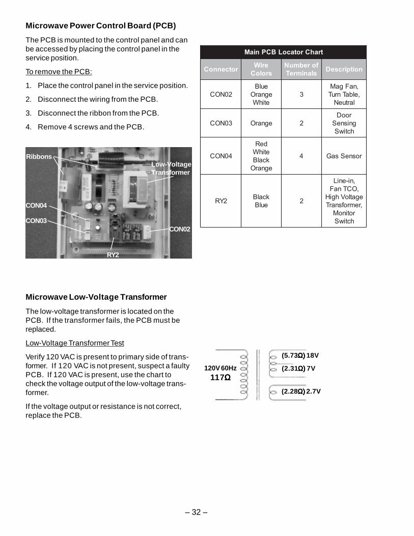
Microwave Power Control Board (PCB)
The PCB is mounted to the control panel and canbe accessed by placing the control panel in theservice position.
To remove the PCB:
1. Place the control panel in the service position.
2. Disconnect the wiring from the PCB.
3. Disconnect the ribbon from the PCB.
4. Remove 4 screws and the PCB.
Microwave Low-Voltage Transformer
The low-voltage transformer is located on thePCB. If the transformer fails, the PCB must bereplaced.
Low-Voltage Transformer Test
Verify 120 VAC is present to primary side of trans-former. If 120 VAC is not present, suspect a faultyPCB. If 120 VAC is present, use the chart tocheck the voltage output of the low-voltage trans-former.
If the voltage output or resistance is not correct,replace the PCB.
trahCrotacoLBCPniaM
rotcennoC eriWsroloC
forebmuNslanimreT noitpircseD
20NOCeulBegnarOetihW
3,naFgaM,elbaTnruTlartueN
30NOC egnarO 2rooDgnisneShctiwS
40NOC
deRetihWkcalBegnarO
4 rosneSsaG
2YR kcalBeulB 2
,ni-eniL,OCTnaFegatloVhgiH,remrofsnarT
rotinoMhctiwS
CON04
CON03CON02
RY2
RibbonsLow-VoltageTransformer
120V 60Hz117ΩΩΩΩΩ
(5.73Ω) Ω) Ω) Ω) Ω) 18V
(2.31Ω) Ω) Ω) Ω) Ω) 7V
(2.28Ω) Ω) Ω) Ω) Ω) 2.7V
– 33 –
Microwave Key Panel Test
The control panel circuits from the keys to thePCB can be verified by a continuity test.
Refer to the chart in the mini-manual locatedbehind the control panel.
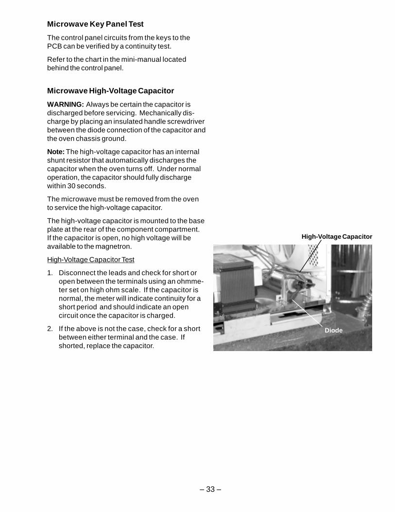
Microwave High-Voltage Capacitor
WARNING: Always be certain the capacitor isdischarged before servicing. Mechanically dis-charge by placing an insulated handle screwdriverbetween the diode connection of the capacitor andthe oven chassis ground.
Note: The high-voltage capacitor has an internalshunt resistor that automatically discharges thecapacitor when the oven turns off. Under normaloperation, the capacitor should fully dischargewithin 30 seconds.
The microwave must be removed from the ovento service the high-voltage capacitor.
The high-voltage capacitor is mounted to the baseplate at the rear of the component compartment.If the capacitor is open, no high voltage will beavailable to the magnetron.
High-Voltage Capacitor Test
1. Disconnect the leads and check for short oropen between the terminals using an ohmme-ter set on high ohm scale. If the capacitor isnormal, the meter will indicate continuity for ashort period and should indicate an opencircuit once the capacitor is charged.
2. If the above is not the case, check for a shortbetween either terminal and the case. Ifshorted, replace the capacitor.
High-Voltage Capacitor
Diode
– 34 –
Microwave High-Voltage Diode
The microwave must be removed from the oven toservice the high-voltage diode.
WARNING: Discharge the high-voltage capacitor beforetouching any oven components or wiring.
The high-voltage diode is connected to the high-voltagecapacitor and is grounded to the chassis.
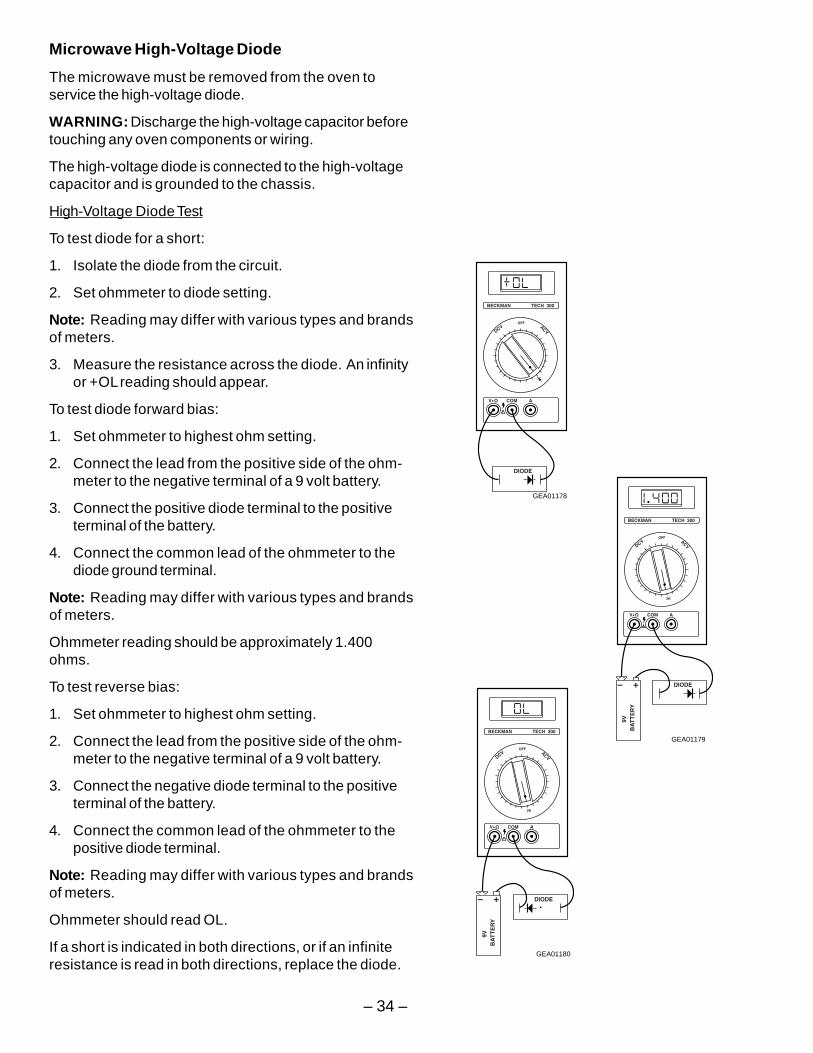
High-Voltage Diode Test
To test diode for a short:
1. Isolate the diode from the circuit.
2. Set ohmmeter to diode setting.
Note: Reading may differ with various types and brandsof meters.
3. Measure the resistance across the diode. An infinityor +OL reading should appear.
To test diode forward bias:
1. Set ohmmeter to highest ohm setting.
2. Connect the lead from the positive side of the ohm-meter to the negative terminal of a 9 volt battery.
3. Connect the positive diode terminal to the positiveterminal of the battery.
4. Connect the common lead of the ohmmeter to thediode ground terminal.
Note: Reading may differ with various types and brandsof meters.
Ohmmeter reading should be approximately 1.400ohms.
To test reverse bias:
1. Set ohmmeter to highest ohm setting.
2. Connect the lead from the positive side of the ohm-meter to the negative terminal of a 9 volt battery.
3. Connect the negative diode terminal to the positiveterminal of the battery.
4. Connect the common lead of the ohmmeter to thepositive diode terminal.
Note: Reading may differ with various types and brandsof meters.
Ohmmeter should read OL.
If a short is indicated in both directions, or if an infiniteresistance is read in both directions, replace the diode.
GEA01180
GEA01178
GEA01179
– 35 –
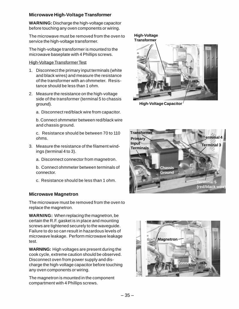
Microwave High-Voltage Transformer
WARNING: Discharge the high-voltage capacitorbefore touching any oven components or wiring.
The microwave must be removed from the oven toservice the high-voltage transformer.
The high-voltage transformer is mounted to themicrowave baseplate with 4 Phillips screws.
High-Voltage Transformer Test
1. Disconnect the primary input terminals (whiteand black wires) and measure the resistanceof the transformer with an ohmmeter. Resis-tance should be less than 1 ohm.
2. Measure the resistance on the high-voltageside of the transformer (terminal 5 to chassisground).
a. Disconnect red/black wire from capacitor.
b. Connect ohmmeter between red/black wireand chassis ground.
c. Resistance should be between 70 to 110ohms.
3. Measure the resistance of the filament wind-ings (terminal 4 to 3).
a. Disconnect connector from magnetron.
b. Connect ohmmeter between terminals ofconnector.
c. Resistance should be less than 1 ohm.
Microwave Magnetron
The microwave must be removed from the oven toreplace the magnetron.
WARNING: When replacing the magnetron, becertain the R.F. gasket is in place and mountingscrews are tightened securely to the waveguide.Failure to do so can result in hazardous levels ofmicrowave leakage. Perform microwave leakagetest.
WARNING: High voltages are present during thecook cycle, extreme caution should be observed.Disconnect oven from power supply and dis-charge the high-voltage capacitor before touchingany oven components or wiring.
The magnetron is mounted in the componentcompartment with 4 Phillips screws.
Magnetron Fan
Magnetron
Connector
Transformer
PrimaryInputTerminals
Terminal 5(red/black wire)
ChassisGround
Terminal 3
Terminal 4
High-VoltageTransformer
High-Voltage Capacitor
– 36 –
Magnetron Test
1. Isolate the magnetron from the high-voltagecircuit by disconnecting the magnetron con-nector.
2. Check for continuity across the magnetronfilament leads with an ohmmeter. Resistanceshould be less than 1 ohm.
3. Check for continuity between one magnetronfilament lead and the chassis ground. Thistest should indicate an infinite resistance. Ifthere is continuity, the magnetron is groundedand must be replaced.
4. Check for continuity between the other magne-tron filament lead and the chassis ground.This test should indicate an infinite resistance.If there is continuity, the magnetron isgrounded and must be replaced.
Power output of the magnetron can be measuredby conducting a Performance Test (see MicrowavePerformance Test).
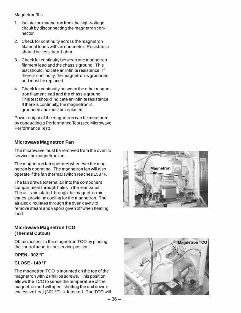
Microwave Magnetron Fan
The microwave must be removed from the oven toservice the magnetron fan.
The magnetron fan operates whenever the mag-netron is operating. The magnetron fan will alsooperate if the fan thermal switch reaches 158 °F.
The fan draws external air into the componentcompartment through holes in the rear panel.The air is circulated through the magnetron airvanes, providing cooling for the magnetron. Theair also circulates through the oven cavity toremove steam and vapors given off when heatingfood.
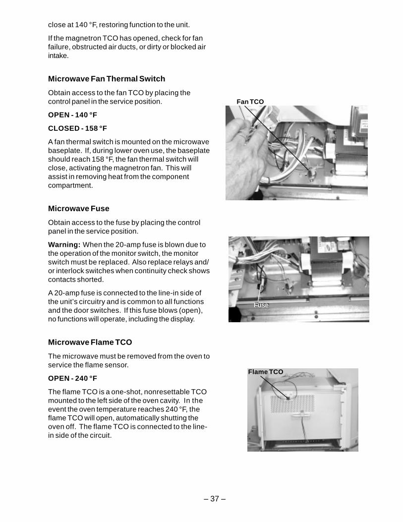
Microwave Magnetron TCO(Thermal Cutout)
Obtain access to the magnetron TCO by placingthe control panel in the service position.
OPEN - 302 °F
CLOSE - 140 °F
The magnetron TCO is mounted on the top of themagnetron with 2 Phillips screws. This positionallows the TCO to sense the temperature of themagnetron and will open, shutting the unit down ifexcessive heat (302 °F) is detected. The TCO will
MagnetronFan
Magnetron TCO
– 37 –
close at 140 °F, restoring function to the unit.
If the magnetron TCO has opened, check for fanfailure, obstructed air ducts, or dirty or blocked airintake.
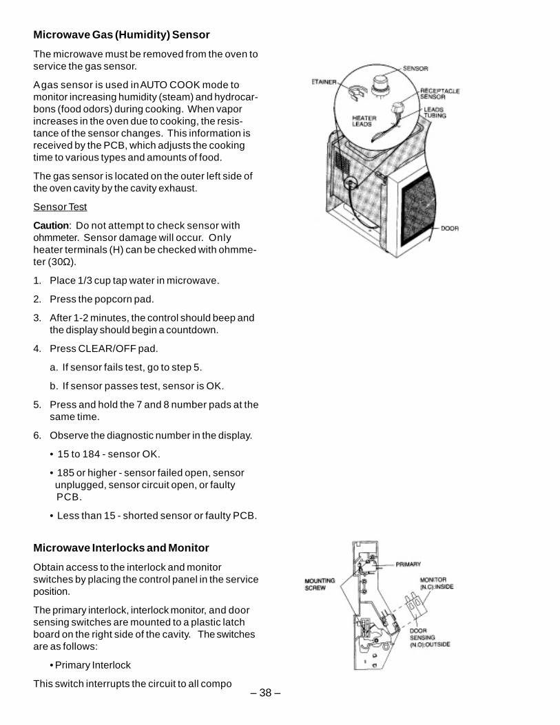
Microwave Fan Thermal Switch
Obtain access to the fan TCO by placing thecontrol panel in the service position.
OPEN - 140 °F
CLOSED - 158 °F
A fan thermal switch is mounted on the microwavebaseplate. If, during lower oven use, the baseplateshould reach 158 °F, the fan thermal switch willclose, activating the magnetron fan. This willassist in removing heat from the componentcompartment.
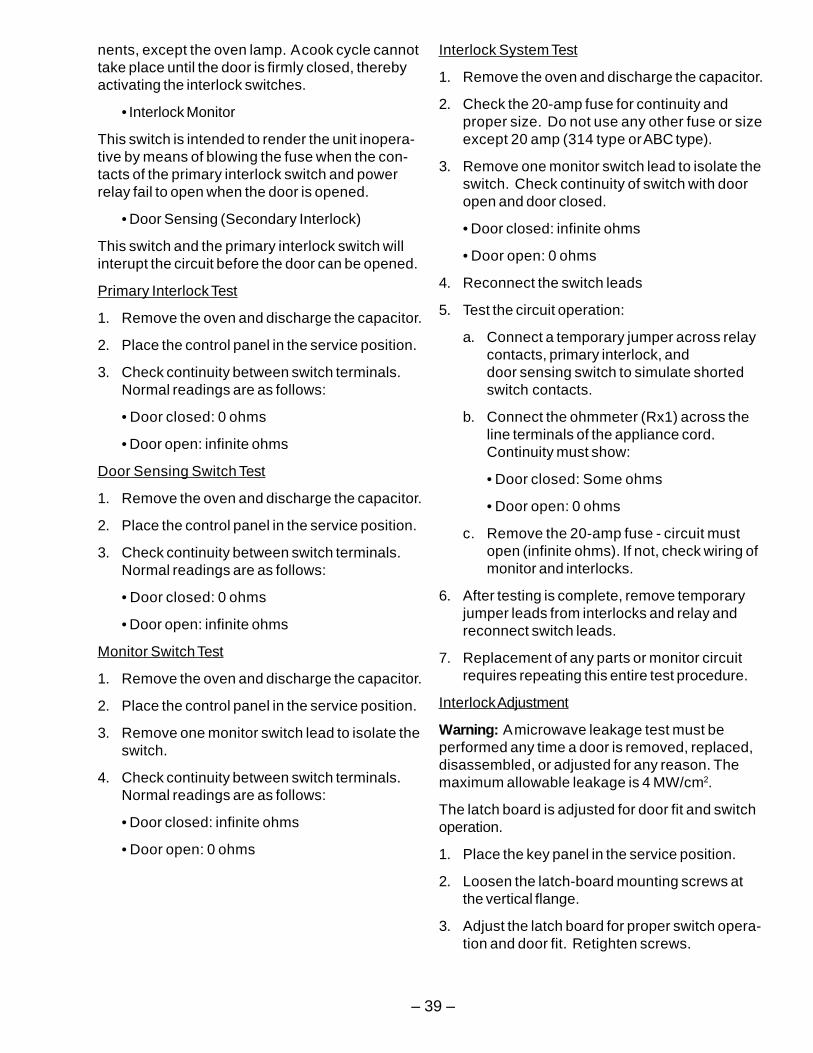
Microwave Fuse
Obtain access to the fuse by placing the controlpanel in the service position.
Warning: When the 20-amp fuse is blown due tothe operation of the monitor switch, the monitorswitch must be replaced. Also replace relays and/or interlock switches when continuity check showscontacts shorted.
A 20-amp fuse is connected to the line-in side ofthe unit’s circuitry and is common to all functionsand the door switches. If this fuse blows (open),no functions will operate, including the display.
Microwave Flame TCO
The microwave must be removed from the oven toservice the flame sensor.
OPEN - 240 °F
The flame TCO is a one-shot, nonresettable TCOmounted to the left side of the oven cavity. In theevent the oven temperature reaches 240 °F, theflame TCO will open, automatically shutting theoven off. The flame TCO is connected to the line-in side of the circuit.
Fan TCO
Flame TCO
FuseFuse
– 38 –
Microwave Gas (Humidity) Sensor
The microwave must be removed from the oven toservice the gas sensor.
A gas sensor is used in AUTO COOK mode tomonitor increasing humidity (steam) and hydrocar-bons (food odors) during cooking. When vaporincreases in the oven due to cooking, the resis-tance of the sensor changes. This information isreceived by the PCB, which adjusts the cookingtime to various types and amounts of food.
The gas sensor is located on the outer left side ofthe oven cavity by the cavity exhaust.
Sensor Test
Caution: Do not attempt to check sensor withohmmeter. Sensor damage will occur. Onlyheater terminals (H) can be checked with ohmme-ter (30Ω).
1. Place 1/3 cup tap water in microwave.
2. Press the popcorn pad.
3. After 1-2 minutes, the control should beep andthe display should begin a countdown.
4. Press CLEAR/OFF pad.
a. If sensor fails test, go to step 5.
b. If sensor passes test, sensor is OK.
5. Press and hold the 7 and 8 number pads at thesame time.
6. Observe the diagnostic number in the display.
• 15 to 184 - sensor OK.
• 185 or higher - sensor failed open, sensor unplugged, sensor circuit open, or faulty PCB.
• Less than 15 - shorted sensor or faulty PCB.
Microwave Interlocks and Monitor
Obtain access to the interlock and monitorswitches by placing the control panel in the serviceposition.
The primary interlock, interlock monitor, and doorsensing switches are mounted to a plastic latchboard on the right side of the cavity. The switchesare as follows:
• Primary Interlock
This switch interrupts the circuit to all compo
– 39 –
Interlock System Test
1. Remove the oven and discharge the capacitor.
2. Check the 20-amp fuse for continuity andproper size. Do not use any other fuse or sizeexcept 20 amp (314 type or ABC type).
3. Remove one monitor switch lead to isolate theswitch. Check continuity of switch with dooropen and door closed.
• Door closed: infinite ohms
• Door open: 0 ohms
4. Reconnect the switch leads
5. Test the circuit operation:
a. Connect a temporary jumper across relaycontacts, primary interlock, anddoor sensing switch to simulate shortedswitch contacts.
b. Connect the ohmmeter (Rx1) across theline terminals of the appliance cord.Continuity must show:
• Door closed: Some ohms
• Door open: 0 ohms
c. Remove the 20-amp fuse - circuit mustopen (infinite ohms). If not, check wiring ofmonitor and interlocks.
6. After testing is complete, remove temporaryjumper leads from interlocks and relay andreconnect switch leads.
7. Replacement of any parts or monitor circuitrequires repeating this entire test procedure.
Interlock Adjustment
Warning: A microwave leakage test must beperformed any time a door is removed, replaced,disassembled, or adjusted for any reason. Themaximum allowable leakage is 4 MW/cm2.
The latch board is adjusted for door fit and switchoperation.
1. Place the key panel in the service position.
2. Loosen the latch-board mounting screws atthe vertical flange.
3. Adjust the latch board for proper switch opera-tion and door fit. Retighten screws.
nents, except the oven lamp. A cook cycle cannottake place until the door is firmly closed, therebyactivating the interlock switches.
• Interlock Monitor
This switch is intended to render the unit inopera-tive by means of blowing the fuse when the con-tacts of the primary interlock switch and powerrelay fail to open when the door is opened.
• Door Sensing (Secondary Interlock)
This switch and the primary interlock switch willinterupt the circuit before the door can be opened.
Primary Interlock Test
1. Remove the oven and discharge the capacitor.
2. Place the control panel in the service position.
3. Check continuity between switch terminals.Normal readings are as follows:
• Door closed: 0 ohms
• Door open: infinite ohms
Door Sensing Switch Test
1. Remove the oven and discharge the capacitor.
2. Place the control panel in the service position.
3. Check continuity between switch terminals.Normal readings are as follows:
• Door closed: 0 ohms
• Door open: infinite ohms
Monitor Switch Test
1. Remove the oven and discharge the capacitor.
2. Place the control panel in the service position.
3. Remove one monitor switch lead to isolate theswitch.
4. Check continuity between switch terminals.Normal readings are as follows:
• Door closed: infinite ohms
• Door open: 0 ohms
– 40 –
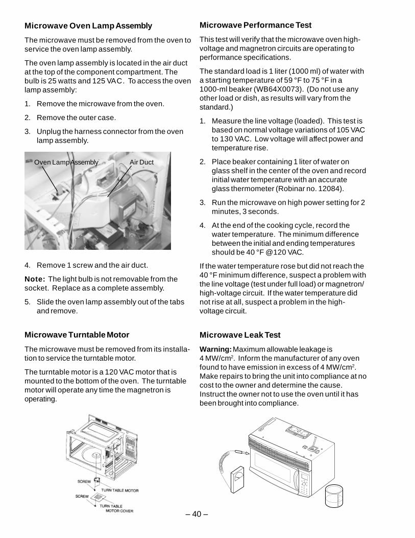
Microwave Oven Lamp Assembly
The microwave must be removed from the oven toservice the oven lamp assembly.
The oven lamp assembly is located in the air ductat the top of the component compartment. Thebulb is 25 watts and 125 VAC. To access the ovenlamp assembly:
1. Remove the microwave from the oven.
2. Remove the outer case.
3. Unplug the harness connector from the ovenlamp assembly.
4. Remove 1 screw and the air duct.
Note: The light bulb is not removable from thesocket. Replace as a complete assembly.
5. Slide the oven lamp assembly out of the tabsand remove.
Microwave Turntable Motor
The microwave must be removed from its installa-tion to service the turntable motor.
The turntable motor is a 120 VAC motor that ismounted to the bottom of the oven. The turntablemotor will operate any time the magnetron isoperating.
Oven Lamp Assembly Air Duct
Microwave Performance Test
This test will verify that the microwave oven high-voltage and magnetron circuits are operating toperformance specifications.
The standard load is 1 liter (1000 ml) of water witha starting temperature of 59 °F to 75 °F in a1000-ml beaker (WB64X0073). (Do not use anyother load or dish, as results will vary from thestandard.)
1. Measure the line voltage (loaded). This test isbased on normal voltage variations of 105 VACto 130 VAC. Low voltage will affect power andtemperature rise.
2. Place beaker containing 1 liter of water onglass shelf in the center of the oven and recordinitial water temperature with an accurateglass thermometer (Robinar no. 12084).
3. Run the microwave on high power setting for 2minutes, 3 seconds.
4. At the end of the cooking cycle, record thewater temperature. The minimum differencebetween the initial and ending temperaturesshould be 40 °F @120 VAC.
If the water temperature rose but did not reach the40 °F minimum difference, suspect a problem withthe line voltage (test under full load) or magnetron/high-voltage circuit. If the water temperature didnot rise at all, suspect a problem in the high-voltage circuit.
Microwave Leak Test
Warning: Maximum allowable leakage is4 MW/cm2. Inform the manufacturer of any ovenfound to have emission in excess of 4 MW/cm2.Make repairs to bring the unit into compliance at nocost to the owner and determine the cause.Instruct the owner not to use the oven until it hasbeen brought into compliance.
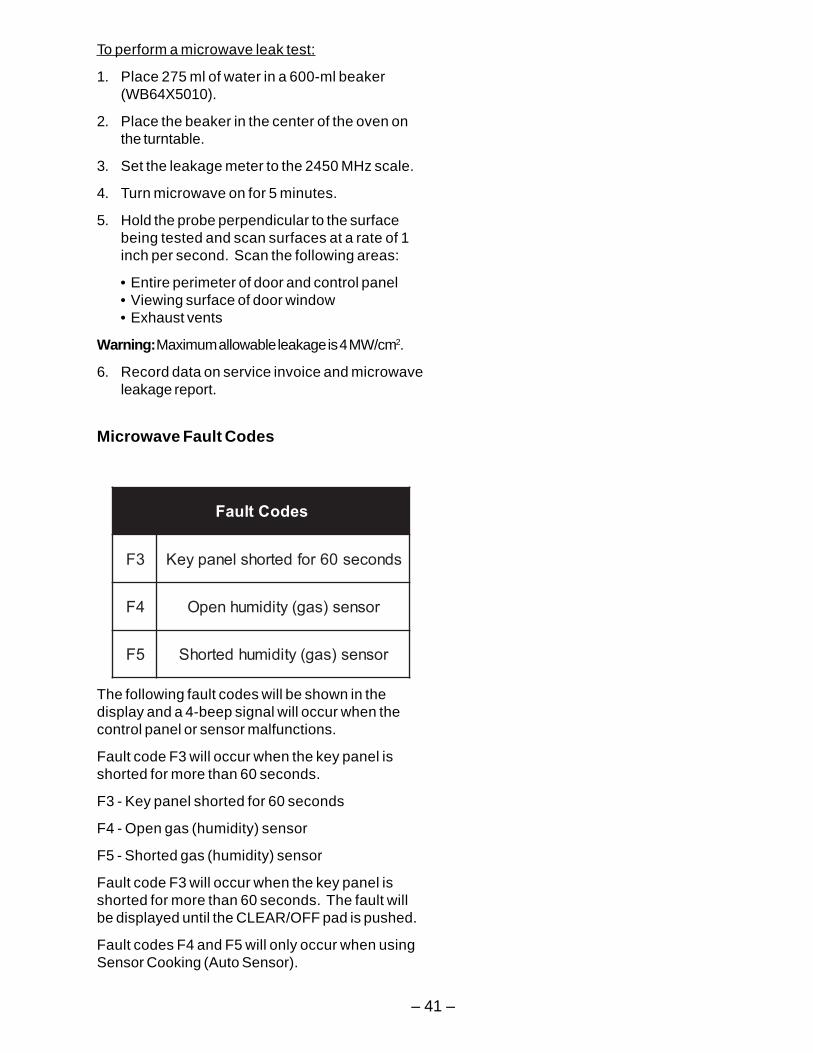
– 41 –
sedoCtluaF
3F sdnoces06rofdetrohslenapyeK
4F rosnes)sag(ytidimuhnepO
5F rosnes)sag(ytidimuhdetrohS
To perform a microwave leak test:
1. Place 275 ml of water in a 600-ml beaker(WB64X5010).
2. Place the beaker in the center of the oven onthe turntable.
3. Set the leakage meter to the 2450 MHz scale.
4. Turn microwave on for 5 minutes.
5. Hold the probe perpendicular to the surfacebeing tested and scan surfaces at a rate of 1inch per second. Scan the following areas:
• Entire perimeter of door and control panel• Viewing surface of door window• Exhaust vents
Warning: Maximum allowable leakage is 4 MW/cm2.
6. Record data on service invoice and microwaveleakage report.
Microwave Fault Codes
The following fault codes will be shown in thedisplay and a 4-beep signal will occur when thecontrol panel or sensor malfunctions.
Fault code F3 will occur when the key panel isshorted for more than 60 seconds.
F3 - Key panel shorted for 60 seconds
F4 - Open gas (humidity) sensor
F5 - Shorted gas (humidity) sensor
Fault code F3 will occur when the key panel isshorted for more than 60 seconds. The fault willbe displayed until the CLEAR/OFF pad is pushed.
Fault codes F4 and F5 will only occur when usingSensor Cooking (Auto Sensor).
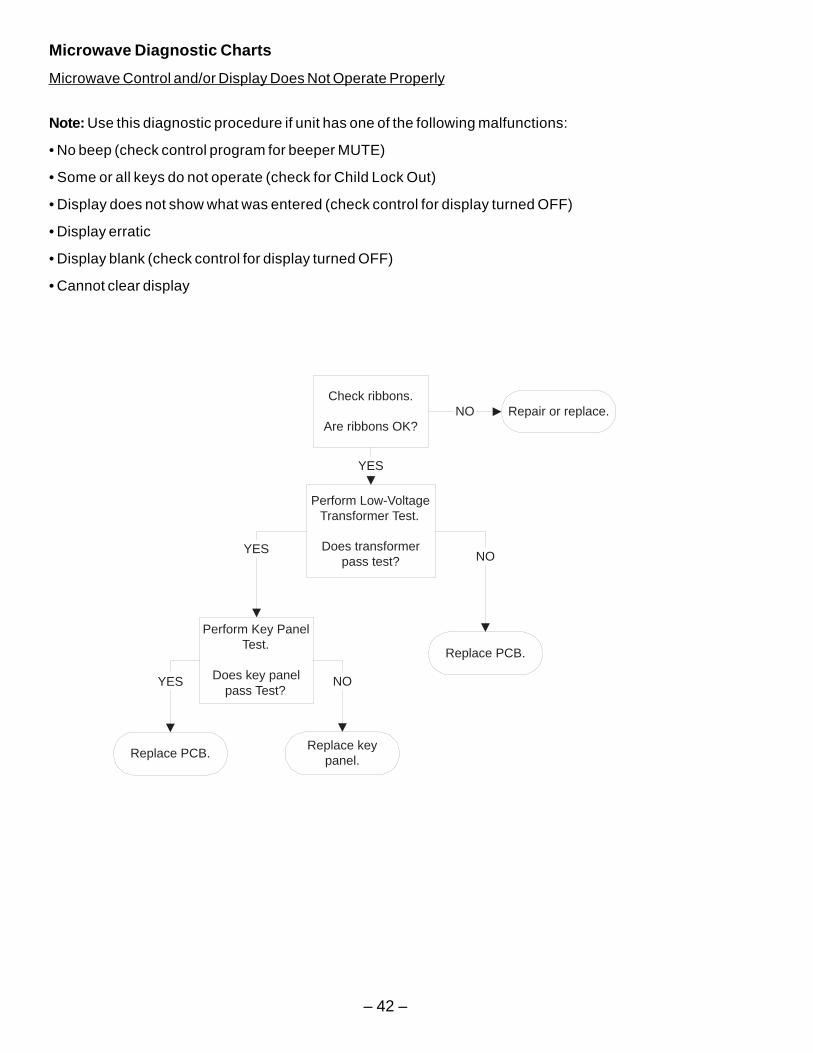
– 42 –
Microwave Diagnostic Charts
Microwave Control and/or Display Does Not Operate Properly
Note: Use this diagnostic procedure if unit has one of the following malfunctions:
• No beep (check control program for beeper MUTE)
• Some or all keys do not operate (check for Child Lock Out)
• Display does not show what was entered (check control for display turned OFF)
• Display erratic
• Display blank (check control for display turned OFF)
• Cannot clear display
Perform Low-VoltageTransformer Test.
Does transformerpass test?
YESNO
Replace PCB.
Perform Key PanelTest.
Does key panelpass Test?
YES NO
Replace keypanel.
Replace PCB.
Check ribbons.
Are ribbons OK?
YES
Repair or replace.NO
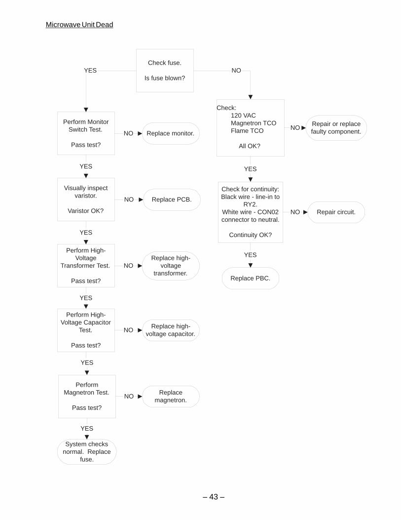
– 43 –
Microwave Unit Dead
Check fuse.
Is fuse blown?
Check: 120 VAC Magnetron TCO Flame TCO
All OK?
NO
Replace PBC.
Repair or replacefaulty component.
NO
Visually inspectvaristor.
Varistor OK?
Replace PCB.NO
Perform MonitorSwitch Test.
Pass test?
Replace monitor.NO
Perform High-Voltage
Transformer Test.
Pass test?
Replace high-voltage
transformer.NO
YES
Perform High-Voltage Capacitor
Test.
Pass test?
Replace high-voltage capacitor.
NO
YES
PerformMagnetron Test.
Pass test?
YES
Replacemagnetron.
NO
System checksnormal. Replace
fuse.
YES
Check for continuity:Black wire - line-in to
RY2.White wire - CON02connector to neutral.
Continuity OK?
YES
Repair circuit.NO
YES
YES
YES
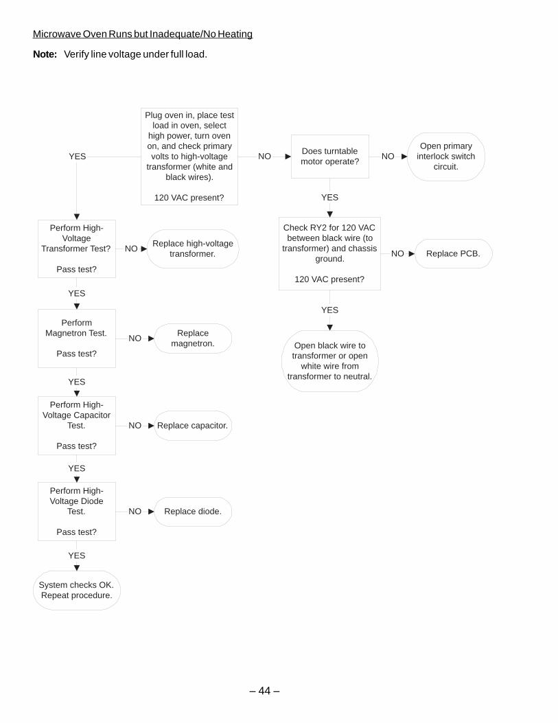
– 44 –
Microwave Oven Runs but Inadequate/No Heating
Note: Verify line voltage under full load.
Plug oven in, place testload in oven, select
high power, turn ovenon, and check primaryvolts to high-voltage
transformer (white andblack wires).
120 VAC present?
Check RY2 for 120 VACbetween black wire (to
transformer) and chassisground.
120 VAC present?
NO
Perform High-Voltage
Transformer Test?
Pass test?
Does turntablemotor operate?
Open primaryinterlock switch
circuit.YES
Replace high-voltagetransformer.
Perform High-Voltage Capacitor
Test.
Pass test?
Replace capacitor.
Perform High-Voltage Diode
Test.
Pass test?
Replace diode.
PerformMagnetron Test.
Pass test?
Replacemagnetron.
System checks OK.Repeat procedure.
NO
NO
YES
NO Replace PCB.NO
YES
Open black wire totransformer or open
white wire fromtransformer to neutral.
NO
NO
YES
YES
YES
YES
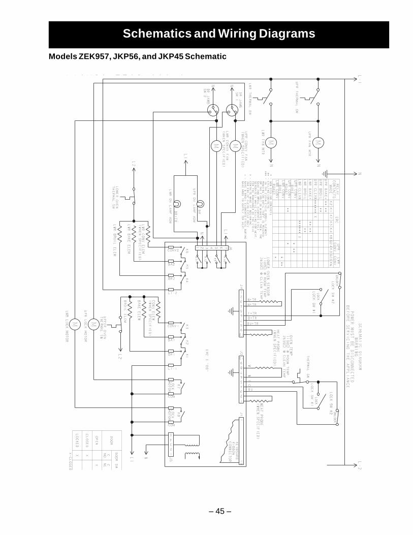
– 45 –
Schematics and Wiring Diagrams
Models ZEK957, JKP56, and JKP45 Schematic
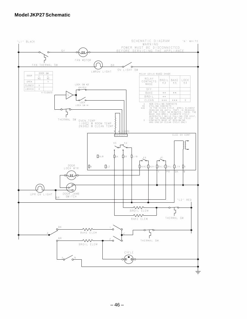
– 46 –
Model JKP27 Schematic
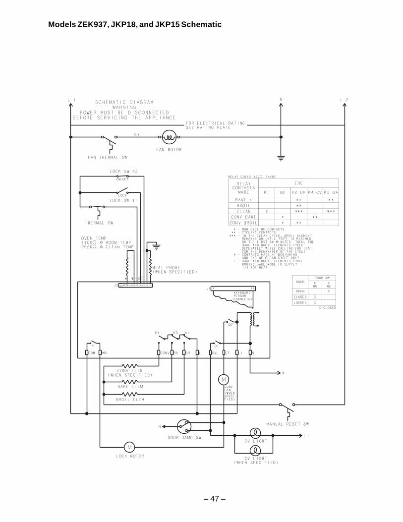
– 47 –
Models ZEK937, JKP18, and JKP15 Schematic
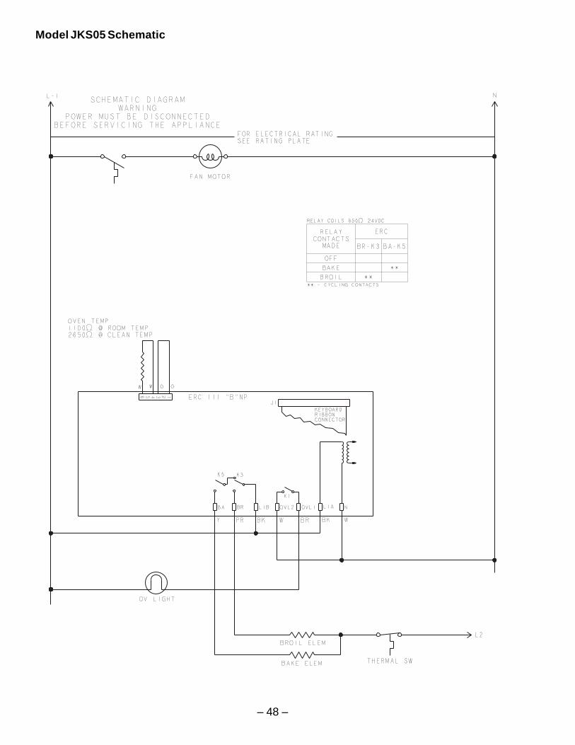
– 48 –
d
Model JKS05 Schematic
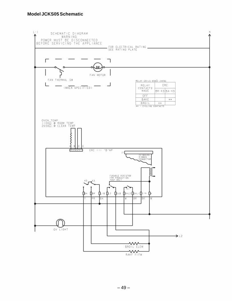
– 49 –
Model JCKS05 Schematic
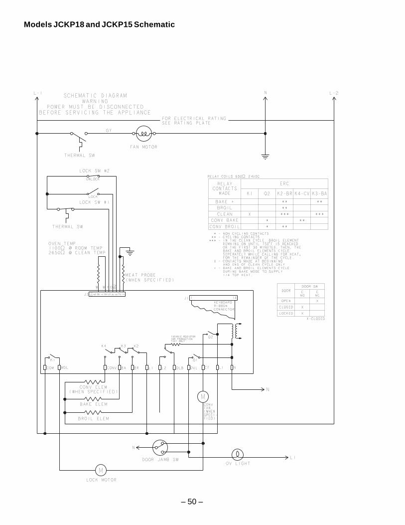
– 50 –
Models JCKP18 and JCKP15 Schematic
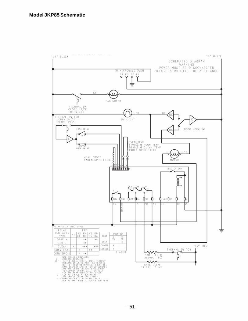
– 51 –
Model JKP85 Schematic
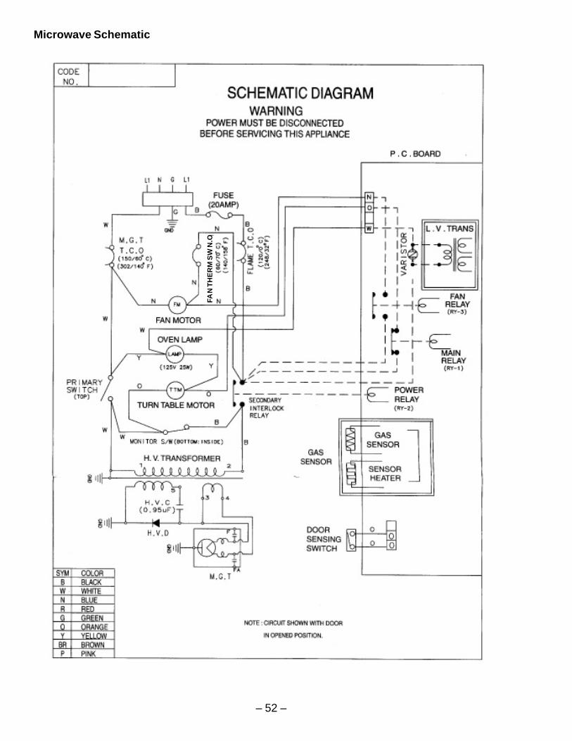
– 52 –
Microwave Schematic
FAN
TH
ER
M S
W N
.O
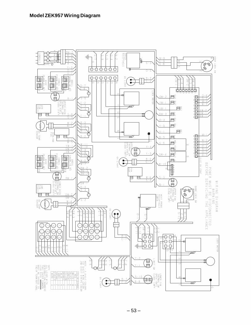
– 53 –
Model ZEK957 Wiring Diagram
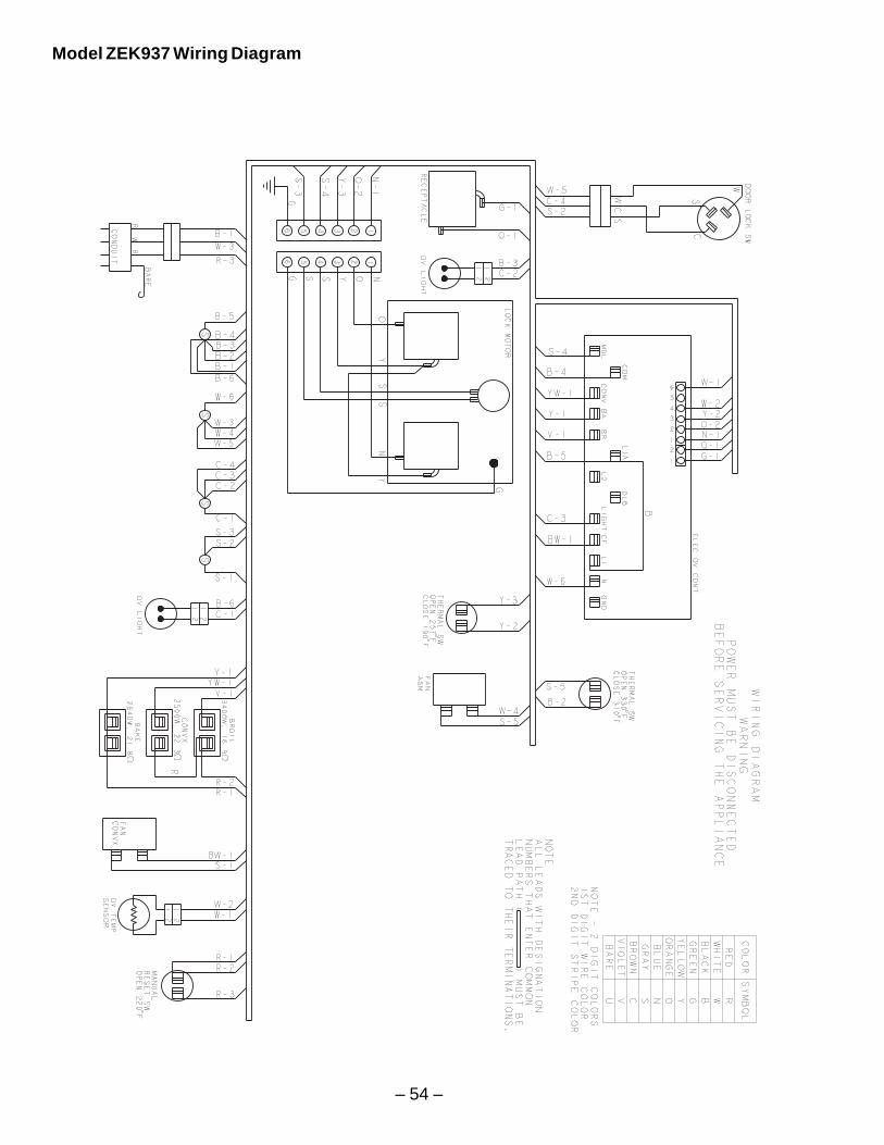
– 54 –
Model ZEK937 Wiring Diagram
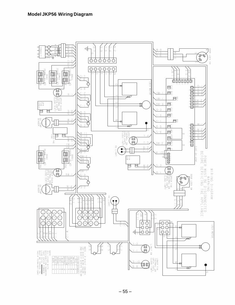
– 55 –
Model JKP56 Wiring Diagram
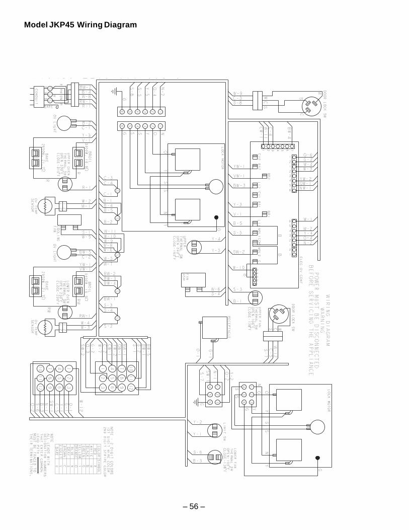
– 56 –
Model JKP45 Wiring Diagram
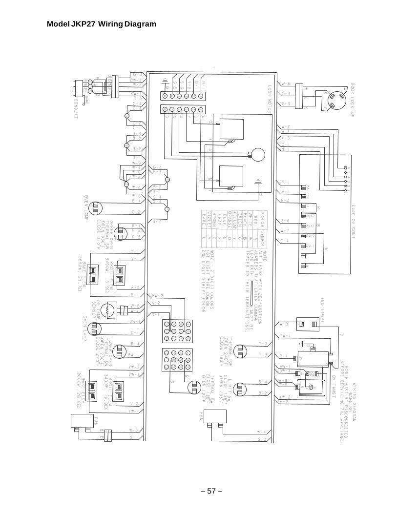
– 57 –
Model JKP27 Wiring Diagram
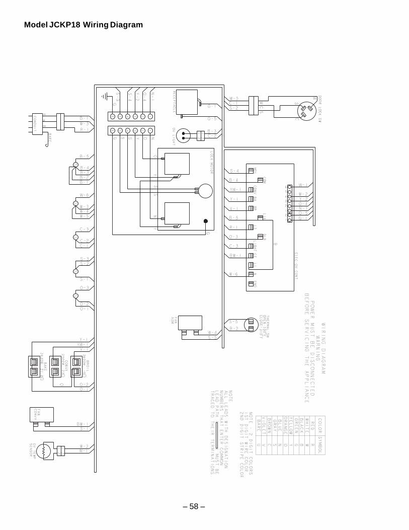
– 58 –
Model JCKP18 Wiring Diagram
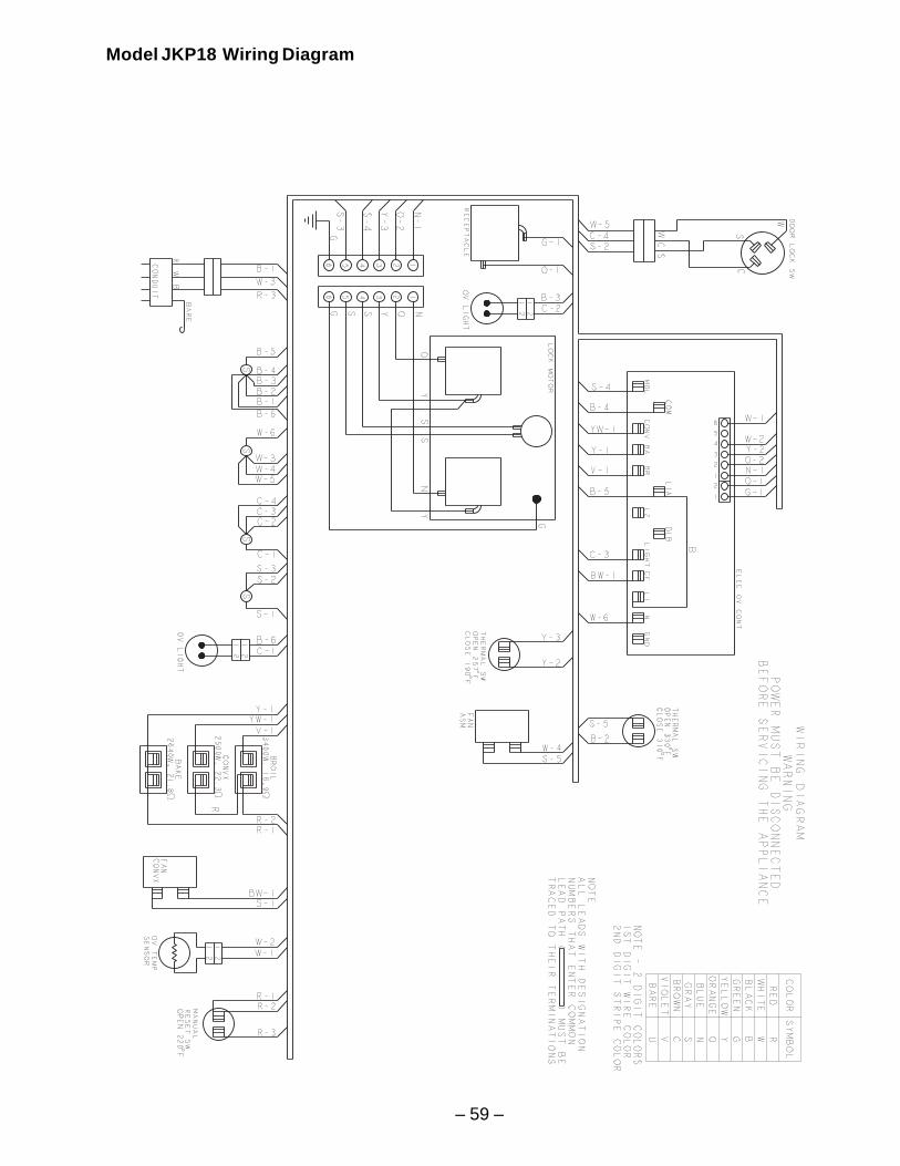
– 59 –
Model JKP18 Wiring Diagram
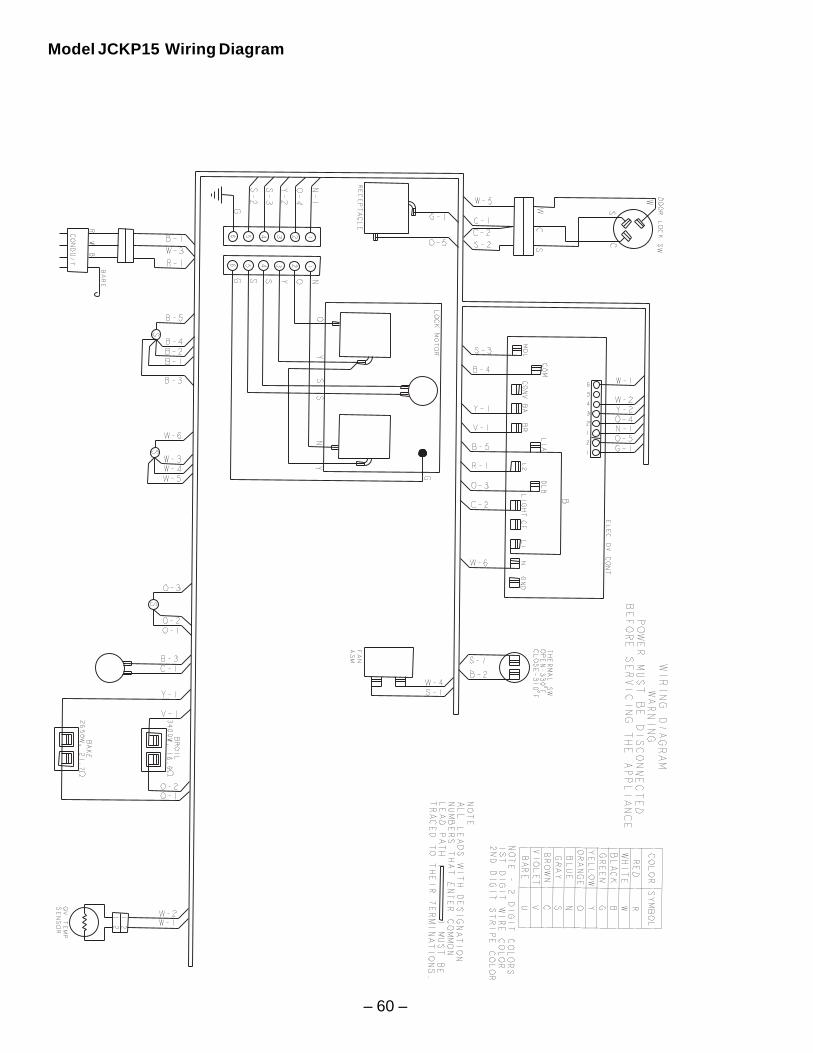
– 60 –
Model JCKP15 Wiring Diagram
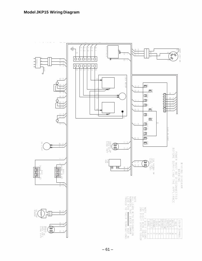
– 61 –
Model JKP15 Wiring Diagram
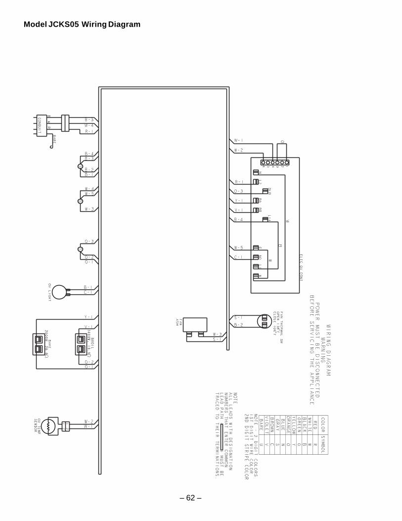
– 62 –
Model JCKS05 Wiring Diagram
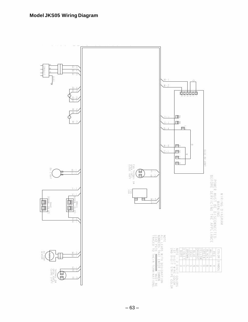
– 63 –
Model JKS05 Wiring Diagram
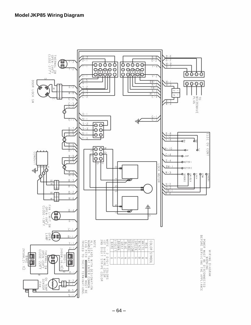
– 64 –
Model JKP85 Wiring Diagram
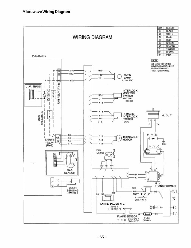
– 65 –
Microwave Wiring Diagram
FAN THERMAL SW N.O.
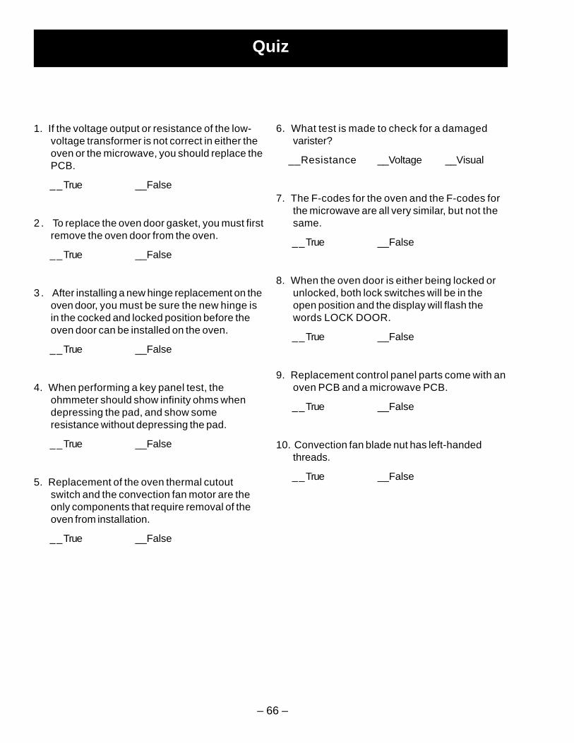
– 66 –
Quiz
1. If the voltage output or resistance of the low-voltage transformer is not correct in either theoven or the microwave, you should replace thePCB.
__True __False
2 . To replace the oven door gasket, you must firstremove the oven door from the oven.
__True __False
3 . After installing a new hinge replacement on theoven door, you must be sure the new hinge isin the cocked and locked position before theoven door can be installed on the oven.
__True __False
4. When performing a key panel test, theohmmeter should show infinity ohms whendepressing the pad, and show someresistance without depressing the pad.
__True __False
5. Replacement of the oven thermal cutoutswitch and the convection fan motor are theonly components that require removal of theoven from installation.
__True __False
6. What test is made to check for a damagedvarister?
__Resistance __Voltage __Visual
7. The F-codes for the oven and the F-codes forthe microwave are all very similar, but not thesame.
__True __False
8. When the oven door is either being locked orunlocked, both lock switches will be in theopen position and the display will flash thewords LOCK DOOR.
__True __False
9. Replacement control panel parts come with anoven PCB and a microwave PCB.
__True __False
10. Convection fan blade nut has left-handedthreads.
__True __False
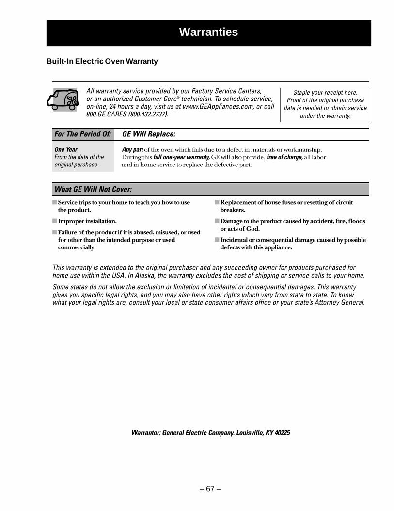
– 67 –
For The Period Of: GE Will Replace:
One Year Any part of the oven which fails due to a defect in materials or workmanship. From the date of the During this full one-year warranty, GE will also provide, free of charge, all labor original purchase and in-home service to replace the defective part.
Service trips to your home to teach you how to use the product.
Improper installation.
Failure of the product if it is abused, misused, or usedfor other than the intended purpose or usedcommercially.
Replacement of house fuses or resetting of circuitbreakers.
Damage to the product caused by accident, fire, floodsor acts of God.
Incidental or consequential damage caused by possibledefects with this appliance.
What GE Will Not Cover:
This warranty is extended to the original purchaser and any succeeding owner for products purchased forhome use within the USA. In Alaska, the warranty excludes the cost of shipping or service calls to your home.
Some states do not allow the exclusion or limitation of incidental or consequential damages. This warrantygives you specific legal rights, and you may also have other rights which vary from state to state. To knowwhat your legal rights are, consult your local or state consumer affairs office or your state’s Attorney General.
Warrantor: General Electric Company. Louisville, KY 40225
Staple your receipt here. Proof of the original purchase
date is needed to obtain serviceunder the warranty.
All warranty service provided by our Factory Service Centers, or an authorized Customer Care® technician. To schedule service,on-line, 24 hours a day, visit us at www.GEAppliances.com, or call800.GE.CARES (800.432.2737).
Warranties
Built-In Electric Oven Warranty
– 68 –
For The Period Of: GE Will Replace:
One Year Any part of the microwave cooking center which fails due to a defect in materials From the date of the or workmanship. During this full one-year warranty, GE will also provide, original purchase free of charge, all labor and in-home service to replace the defective part.
Limited Additional A replacement magnetron tube the magnetron tube fails because of aFour-Year manufacturing defect. During this limited additional four-year warranty, youFor the second through will be responsible for any labor or in-home service.the fifth year from dateof the original purchase
Service trips to your home to teach you how to use the product.
Improper installation.
Failure of the product if it is abused, misused, or used for other than the intended purpose or usedcommercially.
Replacement of house fuses or resetting of circuitbreakers.
Damage to the product caused by accident, fire, floodsor acts of God.
Incidental or consequential damage caused by possibledefects with this appliance.
What GE Will Not Cover:
This warranty is extended to the original purchaser and any succeeding owner for products purchased forhome use within the USA. In Alaska, the warranty excludes the cost of shipping or service calls to your home.
Some states do not allow the exclusion or limitation of incidental or consequential damages. This warrantygives you specific legal rights, and you may also have other rights which vary from state to state. To knowwhat your legal rights are, consult your local or state consumer affairs office or your state’s Attorney General.
Warrantor: General Electric Company. Louisville, KY 40225
All warranty service provided by our Factory Service Centers, oran authorized Customer Care® technician. To schedule service,on-line, 24 hours a day, visit us at www.GEAppliances.com, orcall 800.GE.CARES (800.432.2737).
Staple your receipt here. Proof of the original purchase
date is needed to obtain serviceunder the warranty.
Built-In Microwave Cooking Center Warranty