Embed Size (px)
Citation preview

SECTION TSM 341.1
PAGE 1 OF 19
ISSUE L
TECHNICAL SERVICE MANUAL
CONTENTS
INTRODUCTIONThe illustrations used in this manual are for identification purposes only and cannot be used for ordering parts. Due to the nature of the pump and the close manufacturing tolerances, certain replacement parts are only available in assemblies. Instructions given are for replacing the pump or coupling parts, or entire pumping unit. Always give name of part, model and serial number of the pump when ordering repair parts. The pump model and serial number can be found on the nameplate secured to the pump. In the Viking model number system, the first number “8” indicates a magnetically coupled design. The next two numbers determine the series size and the last two numbers indicate the gear length. SG Series pumps have cast iron construction. SGN pumps feature ductile iron external construction.This manual deals with Model SG-804, SG-805 & SG-807 pumps mounting on the magnetic drive MD-A4, MD-A9, MD-B15 and MD-B40 couplings, as well as Model SG-810 & SG-814 pumps mounting on the magnetic drive MD2-B & MD2-C couplings. Refer to Figures 1 through 26 for general configuration and nomenclature used in this manual. Pump specifications and recommendations are listed in Catalog Section 341.3.
FIGURE 1SG-80514 MD-A4M
Motor Direct Connected To Footless Bracket & Pump
FIGURE 2SG-80711 MD-A9B & Mounted Pump(Counterclockwise Rotation Shaft)
MAGNETIC DRIVE - CAST IRON & DUCTILE IRON PUMPS SERIES SG & SGN
SIZES 804, 805, 807, 810 & 814
Introduction .......................................................................... 1Safety Information & Instructions..........................................2Special Information .............................................................. 3Health Concerns .................................................................. 3Installation ........................................................................... 3Start Up ............................................................................... 5Maintenance ........................................................................ 5MD-A & MD-B Coupling Pump Removal ............................. 7SG-804, -805 & -807 Pump Disassembly............................ 9SG-804, -805 & -807 Pump Assembly................................. 9MD-A & MD-B Coupling Assembly .................................... 10MD2-B & MD2-C Coupling Pump Removal ....................... 11SG-810 & SG-814 Pump Disassembly.............................. 12MD2-B Coupling Disassembly ........................................... 14MD2-C Coupling Disassembly........................................... 14SG-810 & SG-814 Pump Assembly................................... 14Installation of Carbon Graphite Bushings .......................... 14Assembly of Coupling - Series MD2-B & MD2-C .............. 14MD2-B Bearing Carrier Assembly...................................... 15MD2-C Bearing Carrier Assembly ..................................... 15Pressure Relief Valve Instructions ..................................... 16Troubleshooting ................................................................. 16Do’s and Don’ts ................................................................. 17Maintenance ...................................................................... 18Warranty ............................................................................ 19
UNMOUNTED PUMP UNITSCAST IRON DUCTILE IRON Units are designated by the
unmounted pump model number followed by the magnetic coupling size and letter indicating the drive style provided.
D - Direct Drive
M - Motor Mounted (Close Coupled C-Flange)
B - Bearing Carrier Mounted
R - Viking Reducer Drive
P - Commercial Reducer Drive
(Example: SG-80514-MD-A4 B)
SG-80417 -SG-80418 -SG-80425 -SG-80435 -SG-80450 -SG-80470 -SG-80518 SGN-80518SG-80525 SGN-80525SG-80535 SGN-80535SG-80550 SGN-80550SG-80570 SGN-80570SG-80510 SGN-80510SG-80514 SGN-80514SG-80519 SGN-80519SG-80528 SGN-80528SG-80741 SGN-80741SG-80758 SGN-80758SG-80782 SGN-80782SG-80711 SGN-80711SG-80716 SGN-80716SG-80722 SGN-80722SG-80732 SGN-80732SG-81009 -SG-81013 -SG-81026 -SG-81420 -SG-81436 -SG-81456 -
MODEL NUMBER CHART:
Electronic copies of the most current TSM issue can be found on the Viking Pump website at www.vikingpump.com
VIKING PUMP, INC. • A Unit of IDEX Corporation • Cedar Falls, IA 50613 USA

SECTION TSM 341.1 ISSUE L PAGE 2 OF 19
BEFORE opening any liquid chamber (pumping chamber, reservoir, relief valve adjusting cap fitting, etc.) be sure that :
● Any pressure in the chamber has been completely vented through the suction or discharge lines or other appropriate openings or connections.
● The pump drive system means (motor, turbine, engine, etc.) has been “locked out” or otherwise been made non-operational so that it cannot be started while work is being done on the pump.
● You know what material the pump has been handling, have obtained a material safety data sheet (MSDS) for the material, and understand and follow all precautions appropriate for the safe handling of the material.
BEFORE operating the pump, be sure all drive guards are in place.
DO NOT operate pump if the suction or discharge piping is not connected.
DO NOT place fingers into the pumping chamber or its connection ports or into any part of the drive train if there is any possibility of the pump shafts being rotated.
DO NOT exceed the pump’s rated pressure, speed, temperature, or change the system/duty parameters from those the pump was originally supplied, without confirming its suitability for the new service.
BEFORE operating the pump, be sure that:
● It is clean and free from debris
● all valves in the suction and discharge pipelines are fully opened.
● All piping connected to the pump is fully supported and correctly aligned with the pump.
● Pump rotation is correct for the desired direction of flow.
INSTALL pressure gauges/sensors next to the pump suction and discharge connections to monitor pressures.
USE extreme caution when lifting the pump. Suitable lifting devices should be used when appropriate. Lifting eyes installed on the pump must be used only to lift the pump, not the pump with drive and/or base plate. If the pump is mounted on a base plate, the base plate must be used for all lifting purposes. If slings are used for lifting, they must be safely and securely attached. For weight of the pump alone (which does not include the drive and/or base plate) refer to the Viking Pump product catalog.
DO NOT attempt to dismantle a pressure relief valve that has not had the spring pressure relieved or is mounted on a pump that is operating.
AVOID contact with hot areas of the pump and/or drive. Certain operating conditions, temperature control devices (jackets, heat-tracing, etc.), improper installation, improper operation, and improper maintenance can all cause high temperatures on the pump and/or drive.
THE PUMP must be provided with pressure protection. This may be provided through a relief valve mounted directly on the pump, an in-line pressure relief valve, a torque limiting device, or a rupture disk. If pump rotation may be reversed during operation, pressure protection must be provided on both sides of pump. Relief valve adjusting screw caps must always point towards suction side of the pump. If pump rotation is reversed, position of the relief valve must be changed. Pressure relief valves cannot be used to control pump flow or regulate discharge pressure. For additional information, refer to Viking Pump’s Technical Service Manual TSM 000 and Engineering Service Bulletin ESB-31.
THE PUMP must be installed in a matter that allows safe access for routine maintenance and for inspection during operation to check for leakage and monitor pump operation.
WARNING
SAFETY INFORMATION AND INSTRUCTIONS
Danger - Failure to follow the indicated instruction may result in serious injury or death.
Warning - In addition to possible serious injury or death, failure to follow the indicated instruction may cause damage to pump and/or other equipment.
IMPROPER INSTALLATION, OPERATION OR MAINTENANCE OF PUMP MAY CAUSE SERIOUS INJURY OR DEATH AND/OR RESULT IN DAMAGE TO PUMP AND/OR OTHER EQUIPMENT. VIKING’S WARRANTY DOES NOT COVER FAILURE DUE TO IMPROPER INSTALLATION, OPERATION OR MAINTENANCE.
THIS INFORMATION MUST BE FULLY READ BEFORE BEGINNING INSTALLATION, OPERATION OR MAINTENANCE OF PUMP AND MUST BE KEPT WITH PUMP. PUMP MUST BE INSTALLED, OPERATED AND MAINTAINED ONLY BY SUITABLY TRAINED AND QUALIFIED PERSONS.
THE FOLLOWING SAFETY INSTRUCTIONS MUST BE FOLLOWED AND ADHERED TO AT ALL TIMES.
WARNINGSymbolLegend :
!
!
!
!
!
WARNING
!
!
!
WARNING
!
WARNING
!
WARNING
!
WARNING
!

SECTION TSM 341.1 ISSUE L PAGE 3 OF 19
CAUTION !Rare earth magnets used in these couplings have extremely strong magnetic fields capa-ble of changing the performance or damaging items such as the following:
• Pacemakers• Metal implants• Watches• Computers and discs• Credit cards
Completely assembled magnetic couplings will not affect the items listed above.Altered performance or damage can occur only when the coupling halves are separated.There are no known harmful effects of these magnetic fields on the human body itself.
INSTALLATIONGeneralThe following items must be considered prior to pump installation:1. Location - locate the pump as close as possible to
supply of liquid being pumped. If possible locate the pump below liquid supply. Viking pumps are self priming; but, the better the suction conditions the better the pump will perform.
2. Accessibility - pump must be accessible for inspection, maintenance and repair.
SPECIAL INFORMATIONROTATION: Viking Mag Drive® pumps are designed to run in a designated direction (indicated on name plate). Shaft rotation determines which port is suction and which is discharge. Running the pump in the opposite direction may seriously affect the performance of the unit and the relief valve (if present) will not operate. If rotation must be reversed, contact your Viking Pump supplier for instructions and parts to change over.1. A pressure relief valve is mounted as standard on the
SG/SGN series magnetically coupled pumps.2. The SG/SGN series is a positive displacement pump
and requires some form of over pressure protection. Without pressure protection, if the discharge line is blocked or becomes closed, pressure will build up until the motor stalls, drive equipment fails, a pump part breaks, or the piping and/or other equipment in the system bursts.This may be an integral pressure relief valve supplied with the pump, a torque limiting device or a rupture disk.
3. Do not use decoupling of magnets as protection from over pressure. SG/SGN Series pumps can develop potentially damaging pressure before the magnets decouple. Decoupling of the magnets may also cause damage to the magnets themselves.
4. The relief valve adjusting screw cap must always point toward suction side of pump.
5. Pressure relief valves cannot be used to control flow or regulate pressure.
For additional information on pressure relief valves. Refer to Technical Service Manual TSM000 and Engineering Service Bulletin ESB-31.
DANGER !Before opening any Viking pump liquid chamber (pumping chamber, reservoir, relief valve adjusting cap fitting etc.) Be sure:1. That any pressure in the chamber has
been completely vented through the suction or discharge lines or other appropriate openings or connections.
2. That the driving means (motor, turbine, engine, etc.) has been “locked out” or made non- operational so that it cannot be started while work is being done on pump.
3. That you know what liquid the pump has been handling and the precautions necessary to safely handle the liquid. Obtain a material safety data sheet (MSDS) for the liquid to be sure these precautions are understood.
Failure to follow above listed precautionary measures may result in serious injury or death.
SGN - 81013 - M 0 V USpur Gear Principle Design Series Bracket:
M = Metric (ISO) Bracket for IEC Motor Mount (-10,-14)U = SAE Bracket for NEMA Motor Mount (-10,-14)
Relief Valve:O = Without ValveV = With Valve(Single Pumps only)
Shaft Rotation:(Viewed from shaft end)0 = Clockwise1 = Counter-Clockwise
Seal Type:8 = Mag Drive
Material of Construction:Blank = Cast Iron N = Ductile Iron (-805,-807)
Frame Size Pump Size

S D
S D
S D
USE STRAIGHT EDGE. THESE SURFACES MUST BE PARALLEL
CHECK WIDTH BETWEEN THESE SURFACES WITH INSIDE CALIPERS TO BE CERTAIN THE FACES ARE EQUAL DISTANCE APART AND PARALLEL
COUPLINGALIGNMENT
FIGURE 6
SECTION TSM 341.1 ISSUE L PAGE 4 OF 19
MountingWhen using an M drive configuration, alignment is insured by the coupling bracket. If the unit features a bearing carrier, then a flexible coupling will be required and care should be given to properly align the bearing carrier to the motor. See “Alignment” on this page.Since the magnetic coupling is integral to the mounting of the pump, more specific information is presented under the ASSEMBLY and DISASSEMBLY sections presented elsewhere.1. Pump mounting surface and canister outer surface must
be clean and free of metal particles.2. Mounting capscrews must be torqued evenly. See
TABLE 1 below for recommended torque value.
Piping/HoseThe cause of many pumping problems can be traced to suction piping. It should always be as large in diameter and as short in length as possible.Before starting the layout and installation of your piping system, consider the following points:1. Never use piping smaller than the pump port connections.
Piping larger in diameter than the port connection is sometimes is required to reduce suction losses.
2. Be sure the inside of the pipe is clean before installing.3. When approaching an obstacle in the suction line, go
around instead of over it. Going over obstacle creates an air pocket. Where practical slope the piping so no air or liquid pockets will be formed. Air pockets in the suction line make it hard for the pump to prime.
4. A strainer on the suction side of the pump should always be considered in any pumping system. The strainer will keep foreign matter from entering the pump. The strainer mesh or perforation size should be as fine as possible to protect the pump without causing excessive pressure drop. Use of a strainer is particularly important at start up to help clean the system of weld beads, pipe scale and other foreign objects.
5. A pressure relief valve is required in the discharge line. See Pressure Relief Valves, SPECIAL INFORMATION, page 3.
6. Pump must not be used to support piping. The weight of the pipe must be carried by hangers, supports, stands, etc.
FT-LBs: Nm:
804 12-15 16-20805 12-15 16-20807 31-34 42-46810 50-65 68-88814 50-65 68-88
TABLE 1
FIGURE 3Clockwise Rotation
of 804 & 805(Viewed From Shaft End)
FIGURE 4Clockwise Rotation
of 807(Viewed From Shaft End)
FIGURE 5Clockwise Rotation
of 810 & 814(Viewed From Shaft End)
General Cont’d3. Suction/Discharge - SG/SGN Series pumps are designed
for clockwise rotation as standard (viewed from end of shaft). Refer to Figure 3, Figure 4 and Figure 5. Always check rotation arrow on nameplate before mounting and start-up.
3. Do not strike or press the inner magnet coupling half to install on the pump shaft. Damage to the pump or coupling may result if the coupling does not slide onto pump shaft, inspect the coupling bore, shaft and key for nicks or burrs and remove if present.
4. Once the pump has been mounted, place a small amount of compatible liquid into the suction port and turn by hand to ensure the pump turns freely.
AlignmentCheck alignment after mounting on units with a bearing carrier. 1. If the unit has a flexible coupling, remove any coupling
guards or covers and check alignment of the coupling halves. A straight edge (piece of key stock will work) across the coupling must rest evenly on both rims at the top, bottom and sides. See Figure 6.
2. Make final check of alignment after the piping is hooked up. Replace the guards.

SECTION TSM 341.1 ISSUE L PAGE 5 OF 19
START UPBefore pushing the “start” button, check the following:1. Vacuum and pressure gauges (liquid filled) are mounted
on or near the pump. Gauges are the quickest and most accurate way of finding out what is happening in the pump.
2. The pump is correctly aligned.3. There is no pipe strain on the pump.4. Pump turns freely by hand. If the unit features a bearing
carrier then rotate the flexible coupling, but if the unit is motor mounted then carefully try to turn the motor fan blades to turn the pump over.
5. The motor has been jogged and is running in the correct direction. Refer to “General” page 4 item 3.
6. A pressure relief valve is installed properly.7. The suction piping is connected and tight, and the valves
are open.8. The discharge piping is connected and tight, the valves
are open and there is a place for liquid to go.9. All guards are in place.The above checklist is a general guideline to be used prior to starting the pump. Since Viking Pump cannot foresee every application for our product and possible system design, final responsibility is with the user. The pump must be utilized within the catalog specifications and the pump system must be designed to provide safe working conditions.
MAINTENANCECLEANING UNIT: Keep the pump, coupling and motor as clean as possible. This will facilitate inspection, adjustment and repair work.STORAGE: If the pump or coupling are to be stored, drain pump and pour non-detergent SAE 30 weight oil into pump port. Apply grease to pump or coupling shaft extension, if present or accessible. Viking suggests rotating the pump shaft every 30 days to circulate the oil in the pump. The pump and coupling should be stored in a dry area. Note: if the liquid to be pumped reacts with oil, use an acceptable alternate.SUGGESTED REPAIR TOOLS: The following are required to properly repair a SG/SGN Series Mag Drive pump. The tools are in addition to standard mechanics tools such as open end wrenches, pliers, screw drivers, etc. Most of the items can be obtained from an industrial supply house.1. Soft face hammer 2. Allen wrenches3. Internal snap ring pliers (for bearing carriers only)
2-810-029-047-9994. External snap ring pliers 2-810-029-3755. Arbor press6. Torque wrench
7. When fastening the piping to the pump, it should not be necessary to impose any strain on pump casing. “Springing” or “drawing” piping up to the pump will cause distortion, possible misalignment and probable rapid wear of the pump. Do not use pump to correct errors in piping layout or assembly.
8. All joints of piping system must be tight; liquid thread sealant will help assure leak free threaded joints. Loose joints result in liquid leaks or suction side leaks. Air leaks make the pump noisy and reduce flow. CAUTION: Be careful not to over tighten fittings as this can cause cracked joints. Do not use PTFE / plumber’s tape. Reduced friction makes over tightening very easy and will result in cracked ports.
9. Drive alignment must be checked after the piping is hooked up.
10. Provide a pressure relief device if any part of a pump and piping system that can be valved off, thus completely isolated. A rise in temperature will cause liquid to expand. With no provision for pressure relief in the closed off section, there is a chance that the pump or piping will rupture.
Push the “start” button. The pump should begin to deliver liquid within 15 seconds!If the pump does not deliver liquid, push the stop button. Do not run the pump without liquid flow longer than 30 seconds because the pump or coupling could be damaged or ruined. Review steps just outlined. Consider what the suction and discharge gauges indicate. Since the pump will not develop much pressure when filled with air, it may be necessary to vent the discharge line until liquid begins to flow.Reprime the pump and push the “start” button again. If the pump still does not deliver liquid, consider one or more of the following:1. Suction line air leaks.2. The end of the suction pipe is not submerged deep
enough in liquid.3. Suction lift is too great or suction piping is too long.4. Liquid is vaporizing in the suction line before it gets to
the pump.5. Magnetic coupling is decoupling for some reason.If after consideration of these points, the pump still does not deliver liquid, review all points given under START UP and read through the TROUBLESHOOTING guide (page 16) and try again. If pump still will not deliver liquid, contact your Viking Pump supplier.
DANGER !Before starting pump, be sure all drive equipment guards are in place.Failure to properly mount guards may result in serious injury or death.
SECTION TSM 341.1 ISSUE L PAGE 6 OF 19
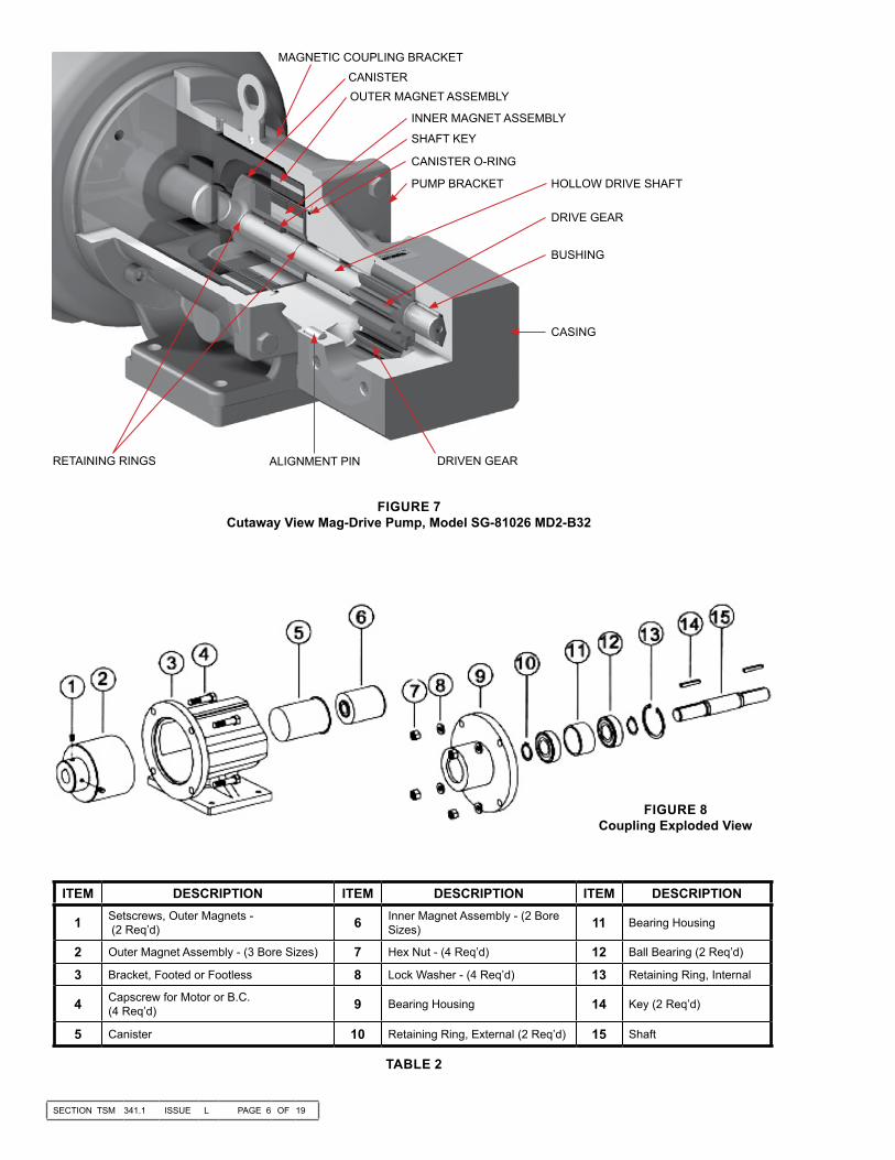
ITEM DESCRIPTION ITEM DESCRIPTION ITEM DESCRIPTION
1 Setscrews, Outer Magnets - (2 Req’d) 6 Inner Magnet Assembly - (2 Bore
Sizes) 11 Bearing Housing
2 Outer Magnet Assembly - (3 Bore Sizes) 7 Hex Nut - (4 Req’d) 12 Ball Bearing (2 Req’d)
3 Bracket, Footed or Footless 8 Lock Washer - (4 Req’d) 13 Retaining Ring, Internal
4 Capscrew for Motor or B.C. (4 Req’d) 9 Bearing Housing 14 Key (2 Req’d)
5 Canister 10 Retaining Ring, External (2 Req’d) 15 Shaft
FIGURE 8Coupling Exploded View
FIGURE 7Cutaway View Mag-Drive Pump, Model SG-81026 MD2-B32
TABLE 2
MAGNETIC COUPLING BRACKETCANISTEROUTER MAGNET ASSEMBLY
INNER MAGNET ASSEMBLY
CANISTER O-RING
PUMP BRACKET HOLLOW DRIVE SHAFT
DRIVE GEAR
BUSHING
CASING
DRIVEN GEARALIGNMENT PINRETAINING RINGS
SHAFT KEY

INNER MAGNET ASSEMBLY
STATIC CANISTER O-RING
RETAININGRINGS
CANISTER
SETSCREWS(2) REQUIRED
CAPSCREWS(4) REQUIRED
BRACKET
PLACE HANDS BACK HERE
DO NOT PLACEFINGERS HERE
SECTION TSM 341.1 ISSUE L PAGE 7 OF 19
BRACKET CAPSCREWS
MD-A & MD-B COUPLINGPUMP REMOVALRead all of the instructions before proceeding with disassembly of the coupling and/or pump.1. Remove piping from the ports and remove the mounting
capscrews securing the pump to the bracket (See Figure 9). Support larger pumps with an overhead hoist if possible.
2. The canister will probably be full of liquid. Use care while removing from the pump and pull straight off. Remove the external snap ring (closest to end of shaft) and slide off the inner magnet assembly (See Figure 11). Use caution, as this is a very strong magnet.
3. Do not remove the canister O-ring unless it is damaged, especially if it is PTFE (Derivative) Encapsulated. If a new O-ring is required, follow instructions in the PUMP ASSEMBLY section, page 10.
4. You should be able to visually inspect the outer magnets from the end of the bracket. If removal is necessary, start by removing the (4) capscrews and separating the bracket from the motor or bearing carrier (See Figure 12). Loosen setscrews in outer magnet assembly to pull assembly off shaft. If the unit features a bearing carrier, the bearings should not require maintenance since they are sealed. If necessary, disassemble by removing the single internal retaining ring (See Figure 8) then press the shaft and bearings out of the housing. Remove the external retaining rings from the shaft to remove bearings.
FIGURE 9
FIGURE 10
FIGURE 11
CAUTION !Use extreme caution, when pulling the inner magnet away from the outer magnet (See Figure 18, page 11). Do not place your fingers between the pump mounting flange and the face of the bracket. If you do not completely pull the pump out it will snap back and could pinch a finger or hand. Once the inner magnet is removed from the bracket be careful setting it down as it will attract any iron or steel object.
(2) Required for SG-807 with MD-A Coupling (4) REQUIRED FOR ALL SG-804 & SG-805, & SG-807 WITH MD-B COUPLING
FIGURE 12
DANGER !Before opening any Viking pump liquid chamber (pumping chamber, reservoir, relief valve adjusting cap fitting etc.) Be sure:1. That any pressure in the chamber has
been completely vented through the suction or discharge lines or other appropriate openings or connections.
2. That the driving means (motor, turbine, engine, etc.) has been “locked out” or made non- operational so that it cannot be started while work is being done on pump.
3. That you know what liquid the pump has been handling and the precautions necessary to safely handle the liquid. Obtain a material safety data sheet (MSDS) for the liquid to be sure these precautions are understood.
Failure to follow above listed precautionary measures may result in serious injury or death.
SECTION TSM 341.1 ISSUE L PAGE 8 OF 19
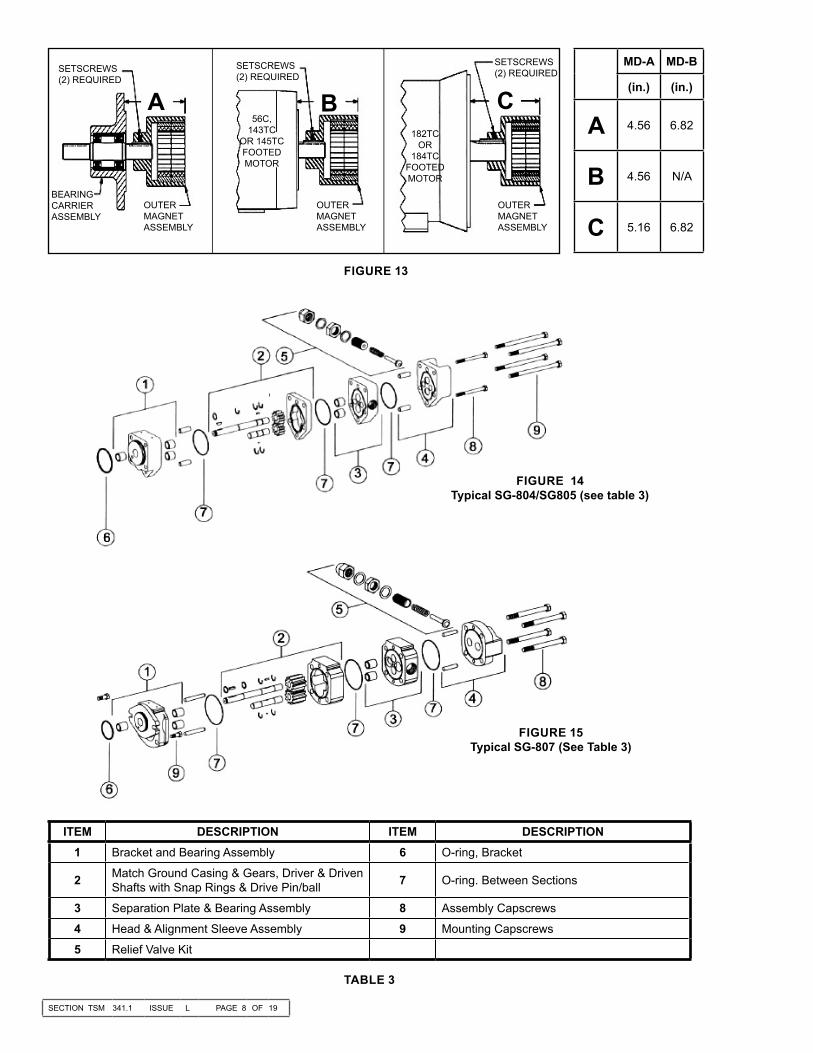
ITEM DESCRIPTION ITEM DESCRIPTION1 Bracket and Bearing Assembly 6 O-ring, Bracket
2 Match Ground Casing & Gears, Driver & Driven Shafts with Snap Rings & Drive Pin/ball 7 O-ring. Between Sections
3 Separation Plate & Bearing Assembly 8 Assembly Capscrews
4 Head & Alignment Sleeve Assembly 9 Mounting Capscrews
5 Relief Valve Kit
TABLE 3
FIGURE 14Typical SG-804/SG805 (see table 3)
FIGURE 15Typical SG-807 (See Table 3)
FIGURE 13
SETSCREWS(2) REQUIRED
BEARINGCARRIERASSEMBLY
OUTERMAGNETASSEMBLY
56C, 143TC
OR 145TCFOOTED MOTOR
SETSCREWS(2) REQUIRED
OUTERMAGNETASSEMBLY
SETSCREWS(2) REQUIRED
OUTERMAGNETASSEMBLY
182TCOR
184TCFOOTED MOTOR
A B C
MD-A MD-B
(in.) (in.)
A 4.56 6.82
B 4.56 N/A
C 5.16 6.82
SECTION TSM 341.1 ISSUE L PAGE 9 OF 19
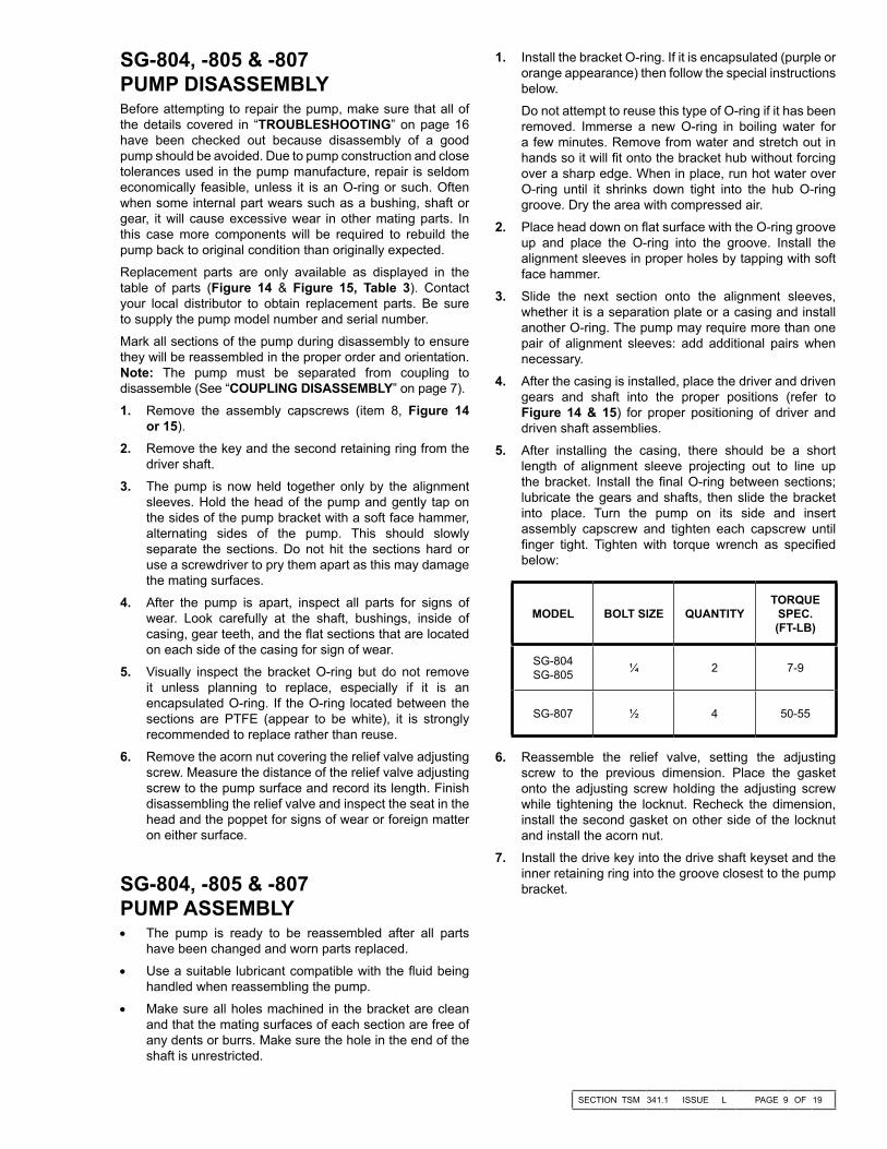
SG-804, -805 & -807 PUMP DISASSEMBLYBefore attempting to repair the pump, make sure that all of the details covered in “TROUBLESHOOTING” on page 16 have been checked out because disassembly of a good pump should be avoided. Due to pump construction and close tolerances used in the pump manufacture, repair is seldom economically feasible, unless it is an O-ring or such. Often when some internal part wears such as a bushing, shaft or gear, it will cause excessive wear in other mating parts. In this case more components will be required to rebuild the pump back to original condition than originally expected.Replacement parts are only available as displayed in the table of parts (Figure 14 & Figure 15, Table 3). Contact your local distributor to obtain replacement parts. Be sure to supply the pump model number and serial number.Mark all sections of the pump during disassembly to ensure they will be reassembled in the proper order and orientation. Note: The pump must be separated from coupling to disassemble (See “COUPLING DISASSEMBLY” on page 7).1. Remove the assembly capscrews (item 8, Figure 14
or 15).2. Remove the key and the second retaining ring from the
driver shaft.3. The pump is now held together only by the alignment
sleeves. Hold the head of the pump and gently tap on the sides of the pump bracket with a soft face hammer, alternating sides of the pump. This should slowly separate the sections. Do not hit the sections hard or use a screwdriver to pry them apart as this may damage the mating surfaces.
4. After the pump is apart, inspect all parts for signs of wear. Look carefully at the shaft, bushings, inside of casing, gear teeth, and the flat sections that are located on each side of the casing for sign of wear.
5. Visually inspect the bracket O-ring but do not remove it unless planning to replace, especially if it is an encapsulated O-ring. If the O-ring located between the sections are PTFE (appear to be white), it is strongly recommended to replace rather than reuse.
6. Remove the acorn nut covering the relief valve adjusting screw. Measure the distance of the relief valve adjusting screw to the pump surface and record its length. Finish disassembling the relief valve and inspect the seat in the head and the poppet for signs of wear or foreign matter on either surface.
SG-804, -805 & -807 PUMP ASSEMBLY• The pump is ready to be reassembled after all parts
have been changed and worn parts replaced.• Use a suitable lubricant compatible with the fluid being
handled when reassembling the pump.• Make sure all holes machined in the bracket are clean
and that the mating surfaces of each section are free of any dents or burrs. Make sure the hole in the end of the shaft is unrestricted.
MODEL BOLT SIZE QUANTITYTORQUE
SPEC.(FT-LB)
SG-804SG-805 ¼ 2 7-9
SG-807 ½ 4 50-55
6. Reassemble the relief valve, setting the adjusting screw to the previous dimension. Place the gasket onto the adjusting screw holding the adjusting screw while tightening the locknut. Recheck the dimension, install the second gasket on other side of the locknut and install the acorn nut.
7. Install the drive key into the drive shaft keyset and the inner retaining ring into the groove closest to the pump bracket.
1. Install the bracket O-ring. If it is encapsulated (purple or orange appearance) then follow the special instructions below.Do not attempt to reuse this type of O-ring if it has been removed. Immerse a new O-ring in boiling water for a few minutes. Remove from water and stretch out in hands so it will fit onto the bracket hub without forcing over a sharp edge. When in place, run hot water over O-ring until it shrinks down tight into the hub O-ring groove. Dry the area with compressed air.
2. Place head down on flat surface with the O-ring groove up and place the O-ring into the groove. Install the alignment sleeves in proper holes by tapping with soft face hammer.
3. Slide the next section onto the alignment sleeves, whether it is a separation plate or a casing and install another O-ring. The pump may require more than one pair of alignment sleeves: add additional pairs when necessary.
4. After the casing is installed, place the driver and driven gears and shaft into the proper positions (refer to Figure 14 & 15) for proper positioning of driver and driven shaft assemblies.
5. After installing the casing, there should be a short length of alignment sleeve projecting out to line up the bracket. Install the final O-ring between sections; lubricate the gears and shafts, then slide the bracket into place. Turn the pump on its side and insert assembly capscrew and tighten each capscrew until finger tight. Tighten with torque wrench as specified below:

SECTION TSM 341.1 ISSUE L PAGE 10 OF 19
ITEM NAME OF PART ITEM NAME OF PART ITEM NAME OF PART1 Bracket & Bushing Assembly 14 Crescent Snap Rings (4 Required) 21 Relief Valve Assembly
2 Bracket 15 Gear Pins (2 Required) 22 Mounting Capscrews (4 Required)
3 Bushings (5 Required) 16 Gears (2 Required) 23 O-Ring for Relief Valve
10 External Retaining Rings (2 Required) 17 Alignment Pins (2 Required) 24 O-Ring for Canister
11 O-ring for Casing 18 Casing & Bushing Assembly 25 Orifice
12 Drive Shaft 19 Casing 26 Key for Inner Magnet
13 Driven Shaft 20 Capscrews (4 Required)
FIGURE 16EXPLODED VIEW – MODELS SG-10 AND SG-14 MAG DRIVE PUMPS
TABLE 4
MD-A & MD-B COUPLING ASSEMBLY
DANGER !
Follow these directions exactly to avoid injury to self or damage to pumping unit. Be careful to keep inner and outer magnets at least (1) foot apart until step 4. Do not engage magnets in any other fashion.
1. Inspect magnets for any metal objects that may be attached. Remove any foreign material. Locate the outer magnet assembly per drawing (See Figure 13 on page 8). Apply Loctite to the set screw threads and tighten both setscrews on to the motor or bearing carrier shaft. The bearing carrier housing features a machined step on its mounting flange, which is the reference point for setting the position of the outer magnet.
2. Mount the bracket to the motor (or bearing carrier to footed bracket) and secure with 4 capscrews (See Figure 12 on page 7). Reach in and rotate magnets by hand to make sure there is no interference. If rubbing occurs, check the dimension. (See Figure 13 on page 8).
3. Slide the inner magnet assembly onto the pump shaft (with key and inner retaining ring in place) and secure
CAUTION !Do not place fingers near mounting surface to avoid pinching (See Figure 9 on page 7).
5. Finish assembly by securing the pump to the bracket. With power disconnected, check to see if the pump turns over freely. This may be done by spinning the motor fan blades or bearing carrier shaft. Use specified torque below:
FT-LBs: Nm:
804 12-15 16-20805 12-15 16-20807 31-34 42-46
TABLE 1
with second retaining ring. Rotate the pump shaft and magnet to make sure they turn freely. Inspect for any foreign particles which could damage the pump. Check the bracket O-ring to make sure it is in good condition and installed properly. Place the canister onto the pump and press on until the canister is in contact with the pump bracket (See Figure 11 on page 7).
4. Remove any foreign particles from the outside of the canister, then slide the canister into the coupling bracket (See Figure 10 on page 7).

SECTION TSM 341.1 ISSUE L PAGE 11 OF 19
FIGURE 18PUMP AND BRACKET SEPARATION SEQUENCE
MD2-B & MD2-C COUPLING PUMP REMOVALRead all of the instructions before proceeding with disassembly of the coupling and/or pump.1. Remove the piping to the ports and remove the
capscrews securing the pump to the bracket. Support the pump with an overhead hoist if possible. Use the M10 x 120 capscrew (jackscrew) in the bracket to separate the inner magnet from the outer. (See Figure 18).
CAUTION !Use extreme caution, when pulling the inner magnet away from the outer magnet (see Figure 18). Do not place your fingers between the pump mounting flange and the face of the bracket. If you do not completely pull the pump out it will snap back and could pinch a finger or hand. Once the inner magnet is removed from the bracket be careful setting it down as it will attract any iron or steel object.
2. The canister will contain some liquid, therefore use care while removing from the pump and pull it straight off. See Figure 19.
FIGURE 17
3. Remove the external snap ring (closest to end of shaft) and slide off the inner magnet assembly (See Figure 20). Use caution, as this is a very strong magnet.
4. Do not remove the canister O-ring unless it is damaged, especially if it is PTFE (Derivative) Encapsulated. If a new O-ring is required, follow instructions in the PUMP ASSEMBLY section, page 12.
5. You should be able to visually inspect the outer magnets from the end of the bracket. If removal is necessary, start by removing the (4) capscrews and separating the bracket from the motor or bearing carrier (See Figure 12, page 7). Loosen setscrews in outer magnet assembly to pull assembly off shaft.
FIGURE 19CANISTER REMOVAL
FIGURE 20INNER MAGNET REMOVAL
BRACKET CAPSCREWS (4)

SECTION TSM 341.1 ISSUE L PAGE 12 OF 19
ITEM DESCRIPTION ITEM DESCRIPTION ITEM DESCRIPTION
601 Bolt-on Hub with Hardware 607 Capscrews (metric) for Pump - 4 Req’d 613 Drive Key - Outboard Side
602 Outer Magnet Assembly 608 Canister and Bushing Assembly 614 Shaft
603 Bracket 609 Inner Magnet Assembly 615 Drive Key - Inboard Side
604 Capscrew (jackscrew) for Disassembly (metric) 610 Capscrews (metric) for Motor or Bearing
Carrier - (4) Req’d 616 Ball Bearing - 2 Req’d
605 Lifting Eye 611 Bearing Carrier Housing 617 Spacer
606 Pipe Plug for Sensor Hole 612 External Retaining Ring - 2 Req’d 618 Internal Retaining Ring
FIGURE 21M DRIVE CONFIGURATION
MD2- B SERIES COUPLING AND BEARING CARRIER COMPONENTS
DANGER !Before opening any Viking pump liquid cham-ber (pumping chamber, reservoir, relief valve adjusting cap fitting etc.) Be sure:1. That any pressure in the chamber has been completely vented through the suction or discharge lines or other appropriate openings or connections.2. That the driving means (motor, turbine, engine, etc.) has been “locked out” or made non- operational so that it cannot be started while work is being done on pump. 3. That you know what liquid the pump has been handling and the precautions necessary to safely handle the liquid. Obtain a material safety data sheet (MSDS) for the liquid to be sure these precautions are understood.Failure to follow above listed precautionary measures may result in serious injury or death.
SG-810 & SG-814 PUMP DISASSEMBLY1. Mark bracket and casing before disassembly to insure
proper reassembly. Remove bracket from pump casing.2. Remove both shaft assemblies.3. To remove the gears from the shafts, remove the snap
rings. The gears should then slide freely off the shaft. NOTE: There is a small pin located under the gear which can fall out of its groove when the gears are removed.
4. If the bearings or bushings need to be replaced: Remove the bearings from the bracket and casing using a Blind Bearing Puller. To remove carbon graphite or silicon carbide bushings, use a cold chisel or punch to break the bushing. Be careful not to damage the bore.

Bearing Carrier Housing
Ball Bearings
External Retaining Rings
Spacer
Internal Retaining Ring
Set ScrewOuter Magnet
Bolt-on Hub
“A”
Tapered Roller Bearing, (Outer)
Lockwasher and Locknut
Retaining End Cap and Setscrew
Lipseal
Set Screw
Inner KeyOuter Magnet
Bolt-on Hub
Spacer
Bearing Carrier Housing
Tapered Roller Bearing, (Inner)
“A”
SECTION TSM 341.1 ISSUE L PAGE 13 OF 19
ITEM DESCRIPTION ITEM DESCRIPTION ITEM DESCRIPTION
601 Bolt-on Hub with Hardware 610 Capscrews (metric) for Motor or Bearing Carrier - 4 Req’d (284 Motor Frame, - 5 req’d) 622 Lip Seal (Outer)
602 Outer Magnet Assembly 611 Bearing Carrier Housing 623 Outer Bearing Spacer
603 Bracket 613 Drive Key - Outboard Side 624 Tapered Roller Bearing - 2 Req’d
604 Capscrew (jackscrew) for Disassembly (metric) 614 Shaft 625 Lip Seal (Inner)
605 Lifting Eye 615 Drive Key - Inboard Side 626 Setscrew - 2 Req’d
606 Pipe Plug for Sensor Hole 617 Inner Bearing Spacer 627 Insert - 2 Req’d
607 Capscrews (metric) for Pump - 4 Req’d 619 Locknut 628 Grease Fitting
608 Canister and Bushing Assembly 620 Lockwasher 629 Adapter (NEMA motor only)
609 Inner Magnet Assembly 621 End Cap 630 Capscrews (metric) for Adaptor - 4 Req’d
FIGURE 22M DRIVE CONFIGURATION
MD2- C SERIES COUPLING AND BEARING CARRIER COMPONENTS
FIGURE 23 MD2-B OUTER MAGNET, BOLT ON HUB
AND BEARING CARRIER
Bearing Carrier for MD2-B Couplings Bearing Carrier for MD2-C Couplings
FIGURE 24MD2-C OUTER MAGNET, BOLT ON HUB
AND BEARING CARRIER

SECTION TSM 341.1 ISSUE L PAGE 14 OF 19
DANGER !Before starting the pump, be sure all drive equipment guards are in place.Failure to properly mount guards may result in serious injury or death.
MD2-C COUPLING DISASSEMBLYThe bearing carrier for the MD2-C coupling features two tapered roller bearings secured by a threaded end cap. The unit is greased externally using the grease fitting. If further disassembly is required, reference Figure 9 on page 7 and Figure 15, then proceed as follows:1. Remove the two setscrews from the bolt-on hub and
slide the outer magnet off of the shaft. Remove the outboard drive key in shaft.
2. Place the inboard side of the shaft in a vise with padded jaws. Bend the lockwasher tab up and gently tap the locknut in a counterclockwise direction. Remove the locknut and lockwasher.
3. Loosen the two setscrews retaining the end cap. Back out the end cap completely. Pull or gently tap the shaft out the back of the bearing housing. Be sure to keep the cup and cone of the outer bearing together. If either the cup or cone requires replacing, it is recommended to replace as a set. The inner cone will probably stay in the housing unless it is to be replaced.
4. One lip seal is pressed into the end cap and the other is pressed into the bearing housing. Do not remove the lipseals unless they require replacement. If removed, pay close attention to the orientation as shown in Figure 15 when installing the new lip seals.
Series MD2-B and MD2-C, All Sizes
DANGER !Follow these directions exactly to avoid injury to self or damage to the pumping unit. Be care-ful to keep the inner and outer magnets at least (1) foot apart until step 4. Do not engage the magnets in any other fashion.
CAUTION !Do not place fingers onto the front of pump mounting flange. Align the canister into bore of the bracket and gently slide it in. When the magnets start to engage, the unit will finish en-gagement on its own very rapidly unless the M10x120mm capscrew is properly used. Make sure fingers are not on the front of the pump. See Figure Sequence 19.
ASSEMBLY OF COUPLING
MODELS RECOMMENDED CAPSCREW TORQUESG-10 / SG-410 80 ft. lbs. (110 Nm)
SG-14 / SG-414 100 ft. lbs. (140 Nm)
SG-810 & SG-814 PUMP ASSEMBLY1. Be sure to clean the bracket and casing thoroughly. If the
bearings were removed, install new pump bearings into each bore using an arbor press. If carbon graphite, Refer to “Installation of Carbon Graphite Bushings” below.
2. Assemble the shaft / gear assemblies. Install one snap ring onto the shaft. Place the anti rotation pin into its groove on the shaft. Slide the gear over the pin and lock into place using the second snap ring. NOTE: Make sure the snap rings do not block the flow path along the gear ID.
3. Coat shaft / gear assemblies with light oil. Place both shafts in the casing with the drive shaft (longer shaft) on the top (nameplate side).
4. Lubricate the casing O-ring and place it in the groove.5. Place the pump bracket onto the casing. Tighten the
capscrews evenly.
MD2-B COUPLING DISASSEMBLYThe bearing carrier for an MD2 B coupling features two sealed ball bearings along with the outer magnet assembly. If further disassembly of this unit is required, reference Figure 8 on page 6 and Figure 14, then proceed as follows:1. Remove the internal retaining ring. Using a press, press
the shaft out of the housing.2. Remove the external retaining rings from shaft. Place
the unit into the press and push out shaft out of the bearings.
INSTALLATION OF CARBON GRAPHITE BUSHINGSWhen installing carbon graphite bushings, extreme care must be taken to prevent breaking. Carbon graphite is a brittle material and is easily cracked. If cracked, the bushing will quickly disintegrate. Using a lubricant and adding a chamfer on the bushing and the mating part will help in installation. The additional precautions listed below must be followed for proper installation.1. A press must be used for installation.2. Be certain bushing is started straight.3. Do not stop pressing operation until bushing is in proper
position. Starting and stopping will result in a cracked bushing.
4. Check bushing for cracks after installation.Carbon graphite bushings with extra interference fits are frequently furnished for high temperature operation. These bushings must be installed by a shrink fit.1. Heat bracket or idler to 750ºF.2. Install cool bushing with a press.3. If facilities are not available to reach 750ºF temperature,
it is possible to install with 450ºF temperature; however the lower the temperature, the greater the possibility of cracking the bushing.
Consult factory with specific questions on high temperature applications.
SECTION TSM 341.1 ISSUE L PAGE 15 OF 19
DANGER !Be certain that the driving means (motor, turbine, engine, etc.) has been “locked out” or made non-operational so that it cannot be started while work is being done on pump.
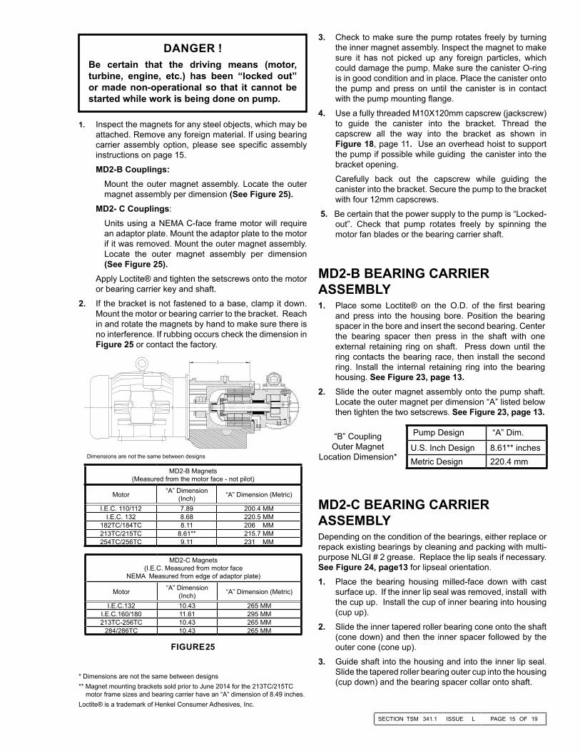
1. Inspect the magnets for any steel objects, which may be attached. Remove any foreign material. If using bearing carrier assembly option, please see specific assembly instructions on page 15.MD2-B Couplings:
Mount the outer magnet assembly. Locate the outer magnet assembly per dimension (See Figure 25).
MD2- C Couplings: Units using a NEMA C-face frame motor will require an adaptor plate. Mount the adaptor plate to the motor if it was removed. Mount the outer magnet assembly. Locate the outer magnet assembly per dimension (See Figure 25).
Apply Loctite® and tighten the setscrews onto the motor or bearing carrier key and shaft.
2. If the bracket is not fastened to a base, clamp it down. Mount the motor or bearing carrier to the bracket. Reach in and rotate the magnets by hand to make sure there is no interference. If rubbing occurs check the dimension in Figure 25 or contact the factory.
Dimensions are not the same between designs
Loctite® is a trademark of Henkel Consumer Adhesives, Inc.
MD2-B Magnets (Measured from the motor face - not pilot)
Motor “A” Dimension (Inch) “A” Dimension (Metric)
I.E.C. 110/112 7.89 200.4 MMI.E.C. 132 8.68 220.5 MM
182TC/184TC 8.11 206 MM213TC/215TC 8.61** 215.7 MM254TC/256TC 9.11 231 MM
MD2-C Magnets (I.E.C. Measured from motor face
NEMA Measured from edge of adaptor plate)
Motor “A” Dimension (Inch) “A” Dimension (Metric)
I.E.C.132 10.43 265 MMI.E.C.160/180 11.61 295 MM213TC-256TC 10.43 265 MM
284/286TC 10.43 265 MM
3. Check to make sure the pump rotates freely by turning the inner magnet assembly. Inspect the magnet to make sure it has not picked up any foreign particles, which could damage the pump. Make sure the canister O-ring is in good condition and in place. Place the canister onto the pump and press on until the canister is in contact with the pump mounting flange.
4. Use a fully threaded M10X120mm capscrew (jackscrew) to guide the canister into the bracket. Thread the capscrew all the way into the bracket as shown in Figure 18, page 11. Use an overhead hoist to support the pump if possible while guiding the canister into the bracket opening. Carefully back out the capscrew while guiding the canister into the bracket. Secure the pump to the bracket with four 12mm capscrews.
5. Be certain that the power supply to the pump is “Locked-out”. Check that pump rotates freely by spinning the motor fan blades or the bearing carrier shaft.
MD2-B BEARING CARRIER ASSEMBLY1. Place some Loctite® on the O.D. of the first bearing
and press into the housing bore. Position the bearing spacer in the bore and insert the second bearing. Center the bearing spacer then press in the shaft with one external retaining ring on shaft. Press down until the ring contacts the bearing race, then install the second ring. Install the internal retaining ring into the bearing housing. See Figure 23, page 13.
2. Slide the outer magnet assembly onto the pump shaft. Locate the outer magnet per dimension “A” listed below then tighten the two setscrews. See Figure 23, page 13.
Pump Design “A” Dim.
U.S. Inch Design 8.61** inches Metric Design 220.4 mm
“B” Coupling Outer Magnet
Location Dimension*
MD2-C BEARING CARRIER ASSEMBLYDepending on the condition of the bearings, either replace or repack existing bearings by cleaning and packing with multi-purpose NLGI # 2 grease. Replace the lip seals if necessary. See Figure 24, page13 for lipseal orientation.1. Place the bearing housing milled-face down with cast
surface up. If the inner lip seal was removed, install with the cup up. Install the cup of inner bearing into housing (cup up).
2. Slide the inner tapered roller bearing cone onto the shaft (cone down) and then the inner spacer followed by the outer cone (cone up).
3. Guide shaft into the housing and into the inner lip seal. Slide the tapered roller bearing outer cup into the housing (cup down) and the bearing spacer collar onto shaft.
FIGURE 25
* Dimensions are not the same between designs** Magnet mounting brackets sold prior to June 2014 for the 213TC/215TC motor frame sizes and bearing carrier have an “A” dimension of 8.49 inches.

SECTION TSM 341.1 ISSUE L PAGE 16 OF 19
4. Thread in the end cap until it meets the outer cup. Install the lockwasher and locknut. Secure the end of the shaft in a vice with padded jaws then tighten the locknut. Tighten the end cap until there is considerable drag on the bearings, then back off the end cap approximately 10°. Secure the end cap into position by tightening the two set screws.
5. Tighten the locknut again, then bend over the appropriate lockwasher tab.
6. Install the inboard drive key, then slide the magnet onto the shaft. Locate the outer magnet per dimension “A” listed below. Tighten the two setscrews to lock into proper position. See Figure 24, page 13.
Pump Design “A” Dim.
U.S. Inch Design 10.43 inches Metric Design 265 mm
“C” Coupling Outer Magnet
Location Dimension
DANGER !Before opening any Viking pump liquid chamber (pumping chamber, reservoir, relief valve adjusting cap fitting etc.) Be sure:1. That any pressure in the chamber has
been completely vented through the suction or discharge lines or other appropriate openings or connections.
2. That the driving means (motor, turbine, engine, etc.) has been “locked out” or made non- operational so that it cannot be started while work is being done on pump.
3. That you know what liquid the pump has been handling and the precautions necessary to safely handle the liquid. Obtain a material safety data sheet (MSDS) for the liquid to be sure these precautions are understood.
Failure to follow above listed precautionary measures may result in serious injury or death.
VALVE - LIST OF PARTS1. Valve Cap 6. Valve Body2. Adjusting Screw 7. Valve Spring3. Lock Nut 8. Poppet4. Spring Guide 9. Cap Gasket5. Bonnet
PRESSURE RELIEF VALVE INSTRUCTIONS
FIGURE 26
DISASSEMBLY – RELIEF VALVE:Mark the valve and head before disassembly to ensure proper reassembly.1. Remove the valve cap.2. Measure and record the length of extension of the
adjusting screw. Refer to “A” on Figure 26. 3. Loosen the locknut and back out the adjusting screw until
spring pressure is released.4. Remove the bonnet, spring guide, spring and poppet from
the valve body. Clean and inspect all parts for wear or damage and replace as necessary.
ASSEMBLY – RELIEF VALVE:Reverse the procedures outlined under DISASSEMBLY – RELIEF VALVE. If the valve is removed for repairs, be sure to replace in the original position. The relief valve adjusting screw cap must always point towards the suction side of the pump. If the pump rotation is reversed, remove the relief valve and turn end for end.
PRESSURE ADJUSTMENT:If a new spring is installed or if pressure setting of pressure relief valve is to be changed from that which the factory has set, the following instructions must be carefully followed.1. Carefully remove valve cap which covers adjusting screw. Loosen locknut which locks adjusting screw so pressure
setting will not change during operation of pump.2. Install a pressure gauge in discharge line for actual
adjusting operation.3. Turn adjusting screw in to increase pressure and out to
decrease pressure.
4. With discharge line closed at point beyond pressure gauge, gauge will show maximum pressure valve will allow while pump is in operation.

SECTION TSM 341.1 ISSUE L PAGE 17 OF 19
TROUBLE SHOOTINGA Viking pump that is properly installed and maintained will give long satisfactory performance.If trouble does develop, one of the first steps toward finding the difficulty is to install a vacuum gauge in the suction line and a pressure gauge in the discharge line. Readings on these gauges often give a clue on where to start looking for trouble.
Vacuum Gauge - Suction PortHigh vacuum reading would indicate:1. Suction line is blocked, a valve is closed, a strainer is
plugged or a pinched suction hose.2. Suction line is too small.3. Liquid is too viscous to flow through piping.4. Lift required too high.Low reading would indicate:1. Air leak in the suction line.2. The end of pipe is not in the liquid.3. The pump is worn.4. The pump is dry and should be primed.Fluttery, jumping or erratic reading would indicate:1. The liquid is vaporizing.2. The liquid is coming to the pump in slugs, possibly an
air leak or insufficient liquid above the end of the suction pipe.
3. Vibrating from cavitation, misalignment, or damaged parts.
4. Decoupling of magnetic coupling, possibly due to pressure spikes.
Pressure Gauge - Discharge PortHigh reading would indicate:1. High viscosity and small diameter and/or lengthy
discharge line.2. Strainer or filter plugged.3. Pressure relief valve set too high.4. Valve in the discharge line partially closed.5. Line is partially plugged from build up on inside of pump,
solidified product or foreign object.6. Liquid in pipe not up to temperature.Low reading would indicate:1. Pressure relief valve set too low.2. Pressure relief valve poppet not seating properly.3. Pump mounting capscrews not torqued to specifications
(SG-804 Series 12-15 ft.-lbs).4. Pump assembly bolts not torqued into specifications
(SG-807 Series 50-55 ft.-lbs).5. Bypass around pump is partially open.6. Too much extra clearance.7. Pump damaged or worn.8. Magnetic coupling is decoupling.
Fluttery, jumping or erratic reading would indicate:1. Cavitation.2. Liquid is coming to the pump in slugs.3. An air leak in the suction line.4. Vibrating from misalignment or mechanical problems.Pump does not pump:1. Lost its prime from an air leak or low level in tank.2. Suction lift is too high.3. Rotating in the wrong direction.4. Motor does not come up to speed.5. Suction and discharge valves are not open.6. Strainer is clogged.7. Bypass valve open, pressure relief valve set too low or
pressure relief valve poppet is stuck open.8. Pump is worn out.9. Any changes in liquid, system or operation that would
help explain the trouble, e.g. new liquid, additional lines or process changes.
10. Temperature changes either in the liquid or the environment.
11. Magnetic coupling is decoupling. Change in application (temperature, pressure, viscosity, etc.) may require additional torque beyond coupling capabilities.
Pump starts, then looses its prime:1. Supply tank is empty.2. Liquid is vaporizng in the suction line.3. Air leak or air pockets in the suction line.4. Pump is worn out.Pump is noisy:1. The pump is being starved (heavy liquid cannot get
to pump fast enough). Increase the suction pump size or reduce the length. If pump is above the liquid, raise the liquid level to approach the liquid level of the pump. If the liquid level is already above pump, increase the head of liquid.
2. Pump is cavitating (liquid vaporizing in suction line). Increase the suction pipe size or reduce the length. If pump is above liquid, raise the liquid level to approach the level of the pump. If the liquid level is already above pump, increase the head of liquid.
3. Check alignment.4. Anchor the base or piping to eliminate vibration.Pump not delivering up to capacity:1. Starving or cavitating - increase the suction pipe size or
reduce the length.2. Strainer is partially clogged.3. An air leak somewhere in the suction line.4. The pump is running too slow. Is the motor the correct
speed and wired up correctly?5. The pressure relief valve is set too low, stuck open or
has a damaged poppet seat.

SECTION TSM 341.1 ISSUE L PAGE 18 OF 19
MAINTENANCE:1. DO make sure any pump that has residual system
pressure in it or that has handled high vapor pressure liquids, has been vented through the suction or discharge lines or other openings provided for this purpose.
2. DO make sure that if the pump is still hooked to driver while maintenance is being performed that the driver has been “locked out” so that it cannot be inadvertently started while work is being done on the pump.
3. DO make sure any pump that has handled a corrosive, flammable, hot or toxic liquid has been drained, flushed, vented and/or cooled before it is disassembled.
4. DO record pump model number and serial number and file for further use.
5. DO obtain, read and keep all maintenance instructions furnished with pump.
Pump Model Number:
Serial Number:
Date Received:
Date Installed:
Distributor:
Comments:
6. A bypass line around pump partially opened.7. The pump worn out.Pump takes too much power (stalls motor):1. Liquid is more viscous than unit is sized to handle.2. System pressure relief valve set too high.3. Coupling is mis-aligned.4. Bushings froze up or liquid set up in the coupling.
DO’S AND DON’TSDo’s and Don’ts for installation, operation and maintenance of Viking pumps to assure safe, long, trouble free operation.Installation:1. DO install pump as close to supply tank as possible.2. DO leave working space around the pumping unit.3. DO use large diameter pipe with short and straight runs.4. DO install a strainer in suction line.5. DO a double check of alignment after unit is mounted
and piping is hooked up.6. DO provide pressure relief valve for discharge side of
pump.7. DO check for proper rotation as indicated on nameplate.8. DO use piping, hose and fittings rated for maximum
system pressure.9. DO check to make sure all guards are in place.10. DO handle magnets with extreme caution remembering
they will attract to any ferrous objects.Operation:1. DON’T run the pump (or coupling especially) at speeds
faster than shown in catalog for that size.2. DON’T allow the pump to develop pressure higher than
those shown in catalog at that size.3. DON’T expose the pump to coupling or temperatures
above or below limits shown in catalog for that design or specific construction.
4. DON’T operate unit without all guards in place.5. DON’T operate pump without a pressure relief valve in
discharge piping; be sure the valve is mounted and set correctly.
6. DON’T operate the pump with all the liquid bypassing through the internal pressure relief valve or without any flow of liquid going through the pump for more than 30 seconds. Operation under either of these conditions may result in a heat build up and damage to the pump or coupling.
7. DO have spare parts, pump or complete standby unit available, particularly if the pump is an essential part of a key operation or process.

SECTION TSM 341.1
PAGE 19 OF 19
ISSUE L
TECHNICAL SERVICE MANUAL MAGNETIC DRIVE - CAST IRON & DUCTILE IRON PUMPS
SERIES SG & SGN SIZES 804, 805, 807, 810 & 814
CAUTION !TO REDUCE THE RISK OF LEAKAGE WITH VIKING MAG DRIVE PUMPS, USERS SHOULD COMPLY WITH THE FOLLOWING GUIDELINES AND ADHERE TO THE FOLLOWING PROCEDURES:
■ Thepumpconfigurationandmaterialsusedinapumpare tailored to the application for which it is ordered. Users should never use a pump for an application thatisdifferentfromtheapplicationspecifiedwhenthepumpwasordered.Thisincludesdifferencesinliquid, speed, pressure, temperature or viscosity.
■ Users must understand the characteristics of liquids they are pumping and be especially aware of any particulates in the liquid. Particulates can cause rapid wear of the bushings, especially if carbon graphite bushings are used. Hard bushings and hard shafts can reduce the risk of rapid wear, but the use of hard materials is not always the optimal solution. In applications involving non-abrasive, non-self lubricating liquids, carbon graphite bushings are typically the preferred material.
■ Users should periodically inspect their pump for wear. This is especially critical and should be carried out with greater frequency when carbon graphite bushings are used or the same pump has not previously been used for the same application, including the same liquid, speed, pressure, temperature and viscosity. Users should promptly replace worn parts when they are discovered.
■ Users should continuously monitor pumps that are handling hazardous liquids. This is especially critical for unmanned, remote locations. If a user does not have in-house expertise in the area of monitoring, it should contact a local engineering firm withmonitoring experience.
VIKING PUMP, INC. • A Unit of IDEX Corporation • Cedar Falls, IA 50613 USA
WARRANTYViking pumps, strainers and reducers are warranted to be free of defects in material and workmanship under normal conditions of use and service. The warranty period varies by type of product. A Viking product that fails during its warranty period under normal conditions of use and service due to a defect in material or workmanship will be repaired or replaced by Viking. At Viking’s sole option, Viking may refund (in cash or by credit) the purchase price paid to it for a Viking product (less a reasonable allowance for the period of use) in lieu of repair or replacement of such Viking product. Viking’s warranty is subject to certain restrictions, limitations, exclusions and exceptions. A complete copy of Viking’s warranty, including warranty periods and applicable restrictions, limitations, exclusions and exceptions, is posted on Viking’s website (www.vikingpump.com/warranty/warranty-info). A complete copy of the warranty may also be obtained by contacting Viking through regular mail at Viking Pump, Inc., 406 State Street, Cedar Falls, Iowa 50613, USA.
THIS WARRANTY IS AND SHALL BE VIKING’S SOLE AND EXCLUSIVE WARRANTY AND IS IN LIEU OF ALL OTHER WARRANTIES, EXPRESS OR IMPLIED, INCLUDING, BUT NOT LIMITED TO, ALL WARRANTIES OF MERCHANTABILITY, FITNESS FOR A PARTICULAR PURPOSE AND NON-INFRINGMENT, ALL OF WHICH OTHER WARRANTIES ARE EXPRESSLY EXCLUDED.
THE RIGHTS AND REMEDIES UNDER THIS WARRANTY ARE AND SHALL BE THE SOLE AND EXCLUSIVE RIGHTS AND REMEDIES AGAINST VIKING. EXCEPT FOR THE SPECIFIC LIABILITIES AND OBLIGATIONS PROVIDED UNDER THIS WARRANTY, VIKING SHALL HAVE NO LIABILITY OR OBLIGATION WITH RESPECT TO ANY PRODUCT CLAIMED TO BE DEFECTIVE IN ANY MANNER.
UNDER NO CIRCUMSTANCES SHALL VIKING BE LIABLE UNDER THIS WARRANTY OR OTHERWISE FOR SPECIAL, INCIDENTAL, INDIRECT, CONSEQUENTIAL OR PUNITIVE DAMAGES OF ANY KIND, INCLUDING, BUT NOT LIMITED TO, LOST OR UNREALIZED SALES, REVENUES, PROFITS, INCOME, COST SAVINGS OR BUSINESS, LOST OR UNREALIZED CONTRACTS, LOSS OF GOODWILL, DAMAGE TO REPUTATION, LOSS OF PROPERTY, LOSS OF INFORMATION OR DATA, LOSS OF PRODUCTION, DOWNTIME, OR INCREASED COSTS, IN CONNECTION WITH ANY PRODUCT, EVEN IF VIKING HAS BEEN ADVISED OR PLACED ON NOTICE OF THE POSSIBILITY OF SUCH DAMAGES AND NOTWITHSTANDING THE FAILURE OF ANY ESSENTIAL PURPOSE OF ANY PRODUCT.
© 12/2016 Viking Pump Inc. All rights reserved