Embed Size (px)
Citation preview
TechnicalService/Training Manual
© SUB-ZERO FREEZER COMPANY INC. 2003 ALL RIGHTS RESERVED JOB AID #3756394 (REVISION D -August, 2003
440000 SSeerriieess440000 SSeerriieessWWiinnee SSttoorraaggeeWWiinnee SSttoorraaggee

400 Series400 Series General Information
1-1
SECTION 1
GENERALINFORMATION
400 Series400 SeriesGeneral Information
1-2
TECHNICAL ASSISTANCE:If you should have any questions regarding this equip-ment, please contact:
Sub-Zero Freezer Co., Inc.Attn: Service Department
P.O.Box 44988Madison, WI 53744-4988
Customer Service & Parts Warranty ClaimsPhone (800) 222-7820
Technical AssistancePhone (800) 919-8324
Customer Service & Technical AssistanceFacsimile (608) 441-5887
Parts Warranty ClaimsFacsimile (608) 441-5886
Service Department E-Mail [email protected]
Office Hours7:00 AM to 7:00 PM Central Time
Monday - Friday
This manual is designed to be used by Authorized Service Personnel only. Sub-Zero Freezer Co., Inc.assumes no responsibility for any repairs made on Sub-Zero refrigeration units by anyone other thanAuthorized Service Technicians.
IMPORTANT SAFETY INFORMATION:
Below are the Product Safety Labels used in this manu-al. The "Signal Words" used are WARNING or CAU-TION.
When reviewing this manual, please note these differ-ent safety labels placed in areas where awareness ofpersonal safety and product safety should be taken.
Below each Product Safety Label is a description of theprecautions to be taken when the signal word isobserved.
INTRODUCTION:This 400 Series Technical Service/Training Manual, Part #3756394, has been compiled to provide the most recentinformation on safety, installation, set-up, design, operation, features, troubleshooting, wiring diagrams, and repairprocedures of the 400 Series units. This information will enable the service technician to troubleshoot and diagnosemalfunctions, perform necessary repairs, and return a 400 Series unit to proper operational status.The service technician should read the complete instructions contained in this training/service manual before initiat-ing any repairs on a 400 Series unit.
PART ORDERING:
Service parts must be ordered through an Authorized Sub-Zero Parts Distributor. Please note that the serial numberof the unit being repaired is often important when ordering service replacement parts. Always refer to the PartsPrice List for any parts that may have substitutions determined by serial number.
INDICATES THAT HAZARDOUS OR UNSAFE PRAC-TICES COULD RESULT IN SEVERE PERSONALINJURY OR DEATH
Indicates that hazardous or unsafe practices couldresult in minor personal injury or product and/orproperty damage
In addition, please pay attention to the signal word“NOTE:”, which highlights information that is especiallyimportant for the section it is in.
400 Series400 Series General Information
1-3
Section 1 - General InformationIntroduction ....................................................................... 1-2Important Safety Information ............................................ 1-2Technical Assistance ........................................................ 1-2Part Ordering .................................................................... 1-2Table of Contents .............................................................. 1-3Warranty Information ........................................................ 1-6Model Description ............................................................. 1-7Wine Storage Temperature Range &Recommended Wine Storage/Serving Temp's ................. 1-9
Section 2 - Installation InformationInstallation Considerations.................................................. 2-2
Unit leveling (Model 424) .............................................. 2-2Unit leveling (Model 427, 427R) ................................... 2-2Unit leveling (Model 430) .............................................. 2-3Door Adjustment (Model 424) ....................................... 2-4Door & Drawer Adjustment (Model 427, 427R) ............ 2-4Door Adjustment (Model 430) ....................................... 2-4Door Stop Adjustment (Model 427, 427R) ................... 2-5Door Stop Installation (Model 430) ............................... 2-5Door Panel Removal & Installation (All Models) ........... 2-5Stainless Steel Door Panel Removal & Installation (Model 424) ................................................................. 2-5Overlay Door Panel Removal & Installation (Model 424) .................................................................. 2-5Door Panel Removal & Installation (Model 427, 427R) ........................................................ 2-6Drawer Panel Removal & Installation (Model 427R) ................................................................ 2-7Stainless Steel Door Panel Removal & Installation (Model 430) .................................................................. 2-7Framed & Overlay Door Panel Removal & Installation (Model 430) .................................................................. 2-8
Section 3 - Electronic Control System InformationWine Storage Electronic Control System:
Wine Storage Electronic Control Terminology and Component Descriptions ................... 3-2Basic Wine Storage Electronic Control System ............. 3-3Wine Storage Control Board Layout & Summary Table ................................... 3-4
Wine Storage Control Panel Layout .............................. 3-5Basic Wine Storage Electronic Control Input Operations ............................. 3-5
Unit ON/OFF .............................................................. 3-5Adjusting Wine Storage Set-Points ............................3-6Wine Storage Lighting System ON/OFF ....................3-6Wine Storage Alarm Bell ON/OFF ............................. 3-6
Functions of the Wine Storage Electronic Control System ............................... 3-7
Sense and Display Average Compartment Temperatures ..................................... 3-7Supply Power to the Lighting System ........................3-8Supply Power to the Evaporator Fans .......................3-9Regulate Refrigerant Valve Activity and Compressor and Condenser Fan Cycling(Prior to Serial #1944319)......................................... 3-10Regulate Refrigerant Valve Activity and Compressor and Condenser Fan Cycling(Starting with Serial #1944319)................................. 3-11Control Wine Storage Off-cycle Defrost ................... 3-12
Unique Wine Storage Electronic Control Input Operations ............................................ 3-13
Temperature Units Selection Mode ......................... 3-13Sabbath Mode ......................................................... 3-14Showroom Mode ..................................................... 3-15
Wine Storage Temperature Alarm Featureand Possible Error Indicators. .................................... 3-16
Warm Temperature Alarm ....................................... 3-16Cold Temperature Alarm ..........................................3-17Thermistor Malfunction Error Indicators .................. 3-17
Wine Storage Diagnostic Mode .................................. 3-19Manual Wine Storage Refrigerant Valve Activation Mode ...............................................3-20Wine Storage Temperature Log Recall Mode ............. 3-21
Wine Storage Temperature Log Index Chart ........... 3-23
427R Refrigerator Electronic Control System:Model 427R Refrigerator Electronic Control Terminology and Component Descriptions ...................3-24Model 427R Basic Refrigerator Electronic Control System ........................................... 3-25Model 427R Refrigerator Control Board Layout & Summary Table ................................. 3-26
Model 427R Refrigerator Control Panel Layout ......... 3-27427R Refrigerator Basic Electronic Control Input Operations ............................................ 3-28
Refrigerator Section ON/OFF .................................. 3-28Adjusting Refrigerator Set-Points ........................... 3-28Refrigerator Drawer Ajar Alarm ON/OFF ................ 3-28
Functions of the 427R Refrigerator Electronic Control System ........................................... 3-29
Sense and Display Average Compartment Temperatures .................................... 3-29Supply Power to the Lighting System ..................... 3-30Supply Power to the Evaporator Fan ....................... 3-31Regulate Refrigerator Compressor Cycling(Prior to Serial #1944319) ...................................... 3-32Regulate Refrigerator Compressor Cycling(Starting with Serial #1944319) .............................. 3-33Refrigerator Off-cycle Defrost ................................. 3-34
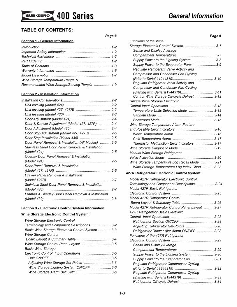
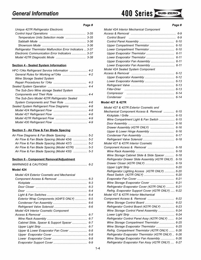
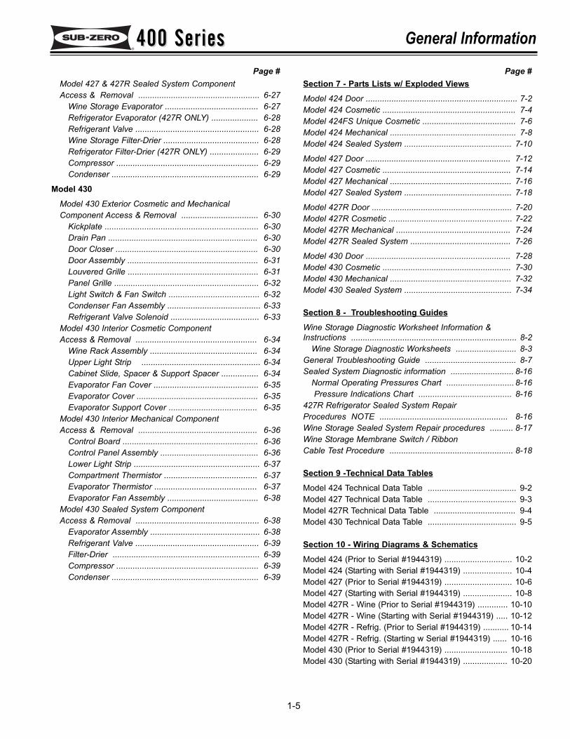
TABLE OF CONTENTS:Page # Page #
400 Series400 SeriesGeneral Information
1-4
Unique 427R Refrigerator Electronic Control Input Operations ........................................... 3-35
Temperature Units Selection mode ......................... 3-35Sabbath Mode ......................................................... 3-36Showroom Mode ..................................................... 3-36
Refrigerator Thermistor Malfunction Error Indicators ... 3-37Electronic Communication Error Indicators .................. 3-37Model 427R Diagnostic Mode .................................... 3-38
Section 4 - Sealed System InformationHFC-134a Refrigerant Service Information ...................... 4-2
General Rules for Working w/134a .............................. 4-2Wine Storage Sealed SystemRepair Procedures for 134a ........................................ 4-3
Sealed System Operation ................................................ 4-4The Sub-Zero Wine storage Sealed SystemComponents and Their Role ......................................... 4-4The Sub-Zero Model 427R Refrigerator SealedSystem Components and Their Role ........................... 4-6
Sealed System Refrigerant Flow Diagrams ..................... 4-8Model 424 Refrigerant Flow ......................................... 4-8Model 427 Refrigerant Flow ......................................... 4-8Model 427R Refrigerant Flow ....................................... 4-9Model 430 Refrigerant Flow ......................................... 4-9
Section 5 - Air Flow & Fan Blade SpacingAir Flow Diagrams & Fan Blade Spacing ......................... 5-2
Air Flow & Fan Blade Spacing (Model 424) ................. 5-2Air Flow & Fan Blade Spacing (Model 427) ................. 5-2Air Flow & Fan Blade Spacing (Model 427R) ............... 5-3Air Flow & Fan Blade Spacing (Model 430) ................. 5-3
Section 6 - Component Removal/AdjustmentWARNINGS & CAUTIONS .............................................. 6-2
Model 424Model 424 Exterior Cosmetic and Mechanical Component Access & Removal .................................... 6-3
Kickplate .................................................................... 6-3Door Closer .............................................................. 6-3Door .......................................................................... 6-4Light & Fan Switches ................................................ 6-4Exterior Wrap Components (424FS ONLY) .............. 6-5Condenser Fan Assembly ......................................... 6-6Refrigerant Valve Solenoid ....................................... 6-6
Model 424 Interior Cosmetic ComponentAccess & Removal ....................................................... 6-7
Wine Rack Assembly ................................................. 6-7Cabinet Slide, Spacer & Support Spacer .................. 6-7Upper Light Strip ................ ...................................... 6-7Upper & Lower Evaporator Fan Cover ...................... 6-8Upper Evaporator Cover ........................................... 6-8Lower Evaporator Cover ........................................... 6-8Evaporator Support Cover ......................................... 6-9
Page # Page #Model 424 Interior Mechanical Component Access & Removal ....................................................... 6-9
Control Board ......................................................... 6-9Control Panel Assembly .......................................... 6-10Upper Compartment Thermistor .............................. 6-10Lower Compartment Thermistor .............................. 6-10Upper Evaporator Thermistor .................................. 6-11Lower Evaporator Thermistor .................................. 6-11Upper Evaporator Fan Assembly ............................. 6-11Lower Evaporator Fan Assembly ............................. 6-11
Model 424 Sealed System Component Access & Removal .................................................... 6-12
Upper Evaporator Assembly .................................... 6-12Lower Evaporator Assembly .................................... 6-13Refrigerant Valve ..................................................... 6-13Filter-Drier ............................................................. 6-13Compressor .......................................................... 6-14Condenser ............................................................ 6-14
Model 427 & 427RModel 427 & 427R Exterior Cosmetic and Mechanical Component Access & Removal ............. 6-15
Kickplate / Grille ....................................................... 6-15Wine Compartment Light & Fan Switch ................... 6-15Door Assembly ........................................................ 6-16Drawer Assembly (427R ONLY) ............................. 6-16Upper & Lower Hinge Assembly ............................. 6-16Condenser Fan Assembly ....................................... 6-17Refrigerant Valve Solenoid ...................................... 6-18
Model 427 & 427R Interior Cosmetic Component Access & Removal ................................ 6-18
Wine Rack Assembly ............................................... 6-18Wine Storage Cabinet Slide & Slide Spacer ........... 6-18Refrigerator Drawer Slide Assembly (427R ONLY) . 6-19Drawer Closer (427R ONLY) ................................... 6-19Upper Light Strip ...................................................... 6-20Refrigerator Lighting Access (427R ONLY) ............. 6-20Reed Switch (427R ONLY) ..................................... 6-20Evaporator Fan Cover ............................................. 6-21Wine Storage Evaporator Cover ............................ 6-21Refrigerator Evaporator Cover (427R ONLY) .......... 6-21Refrig. Evaporator Support Cover (427R ONLY) ..... 6-22
Model 427 & 427R Interior Mechanical Component Access & Removal ................................ 6-22
Wine Storage Control Board ................................... 6-22Refrigerator Control Board (427R ONLY) ................ 6-23Wine Storage Control Panel Assembly .................... 6-24Lower Light Strip ...................................................... 6-24Refrigerator Control Panel Assy (427R ONLY) ....... 6-24Wine Storage Compartment Thermistor ................... 6-25Wine Storage Evaporator Thermistor ...................... 6-25Refrig. Compartment Thermistor (427R ONLY) ....... 6-26Refrigerator Evaporator Thermistor (427R ONLY) .. 6-26Wine Storage Evaporator Fan Assembly ................. 6-26Refrigerator Evaporator Fan Assy (427R ONLY) .... 6-27
400 Series400 Series General Information
1-5
Page # Page #Model 427 & 427R Sealed System Component Access & Removal .................................................... 6-27
Wine Storage Evaporator ........................................ 6-27Refrigerator Evaporator (427R ONLY) .................... 6-28Refrigerant Valve ..................................................... 6-28Wine Storage Filter-Drier ......................................... 6-28Refrigerator Filter-Drier (427R ONLY) ..................... 6-29Compressor ............................................................. 6-29Condenser ............................................................... 6-29
Model 430Model 430 Exterior Cosmetic and Mechanical Component Access & Removal ................................. 6-30
Kickplate .................................................................. 6-30Drain Pan ................................................................ 6-30Door Closer ............................................................. 6-30Door Assembly ........................................................ 6-31Louvered Grille ........................................................ 6-31Panel Grille .............................................................. 6-32Light Switch & Fan Switch ....................................... 6-32Condenser Fan Assembly ........................................ 6-33Refrigerant Valve Solenoid ...................................... 6-33
Model 430 Interior Cosmetic Component Access & Removal .................................................... 6-34
Wine Rack Assembly .............................................. 6-34Upper Light Strip ................................................... 6-34Cabinet Slide, Spacer & Support Spacer ................ 6-34Evaporator Fan Cover ............................................. 6-35Evaporator Cover .................................................... 6-35Evaporator Support Cover ...................................... 6-35
Model 430 Interior Mechanical Component Access & Removal ................................................... 6-36
Control Board .......................................................... 6-36Control Panel Assembly .......................................... 6-36Lower Light Strip ...................................................... 6-37Compartment Thermistor ........................................ 6-37Evaporator Thermistor ............................................ 6-37Evaporator Fan Assembly ....................................... 6-38
Model 430 Sealed System Component Access & Removal ..................................................... 6-38
Evaporator Assembly ............................................... 6-38Refrigerant Valve ..................................................... 6-39Filter-Drier ............................................................... 6-39Compressor ............................................................. 6-39Condenser ............................................................... 6-39
Section 7 - Parts Lists w/ Exploded ViewsModel 424 Door ................................................................. 7-2Model 424 Cosmetic ......................................................... 7-4Model 424FS Unique Cosmetic ........................................ 7-6Model 424 Mechanical ...................................................... 7-8Model 424 Sealed System .............................................. 7-10
Model 427 Door .............................................................. 7-12Model 427 Cosmetic ....................................................... 7-14Model 427 Mechanical .................................................... 7-16Model 427 Sealed System .............................................. 7-18
Model 427R Door ............................................................ 7-20Model 427R Cosmetic ..................................................... 7-22Model 427R Mechanical ................................................. 7-24Model 427R Sealed System ........................................... 7-26
Model 430 Door .............................................................. 7-28Model 430 Cosmetic ....................................................... 7-30Model 430 Mechanical .................................................... 7-32Model 430 Sealed System .............................................. 7-34
Section 8 - Troubleshooting GuidesWine Storage Diagnostic Worksheet Information &Instructions ....................................................................... 8-2
Wine Storage Diagnostic Worksheets .......................... 8-3General Troubleshooting Guide ....................................... 8-7Sealed System Diagnostic information ........................... 8-16
Normal Operating Pressures Chart ............................. 8-16Pressure Indications Chart ........................................ 8-16
427R Refrigerator Sealed System Repair Procedures NOTE ....................................................... 8-16Wine Storage Sealed System Repair procedures .......... 8-17Wine Storage Membrane Switch / Ribbon Cable Test Procedure ..................................................... 8-18
Section 9 -Technical Data TablesModel 424 Technical Data Table ...................................... 9-2Model 427 Technical Data Table ...................................... 9-3Model 427R Technical Data Table ................................... 9-4Model 430 Technical Data Table ...................................... 9-5
Section 10 - Wiring Diagrams & SchematicsModel 424 (Prior to Serial #1944319) ............................. 10-2Model 424 (Starting with Serial #1944319) ..................... 10-4Model 427 (Prior to Serial #1944319) ............................. 10-6Model 427 (Starting with Serial #1944319) ..................... 10-8Model 427R - Wine (Prior to Serial #1944319) ............. 10-10Model 427R - Wine (Starting with Serial #1944319) ..... 10-12Model 427R - Refrig. (Prior to Serial #1944319) ........... 10-14Model 427R - Refrig. (Starting w Serial #1944319) ...... 10-16Model 430 (Prior to Serial #1944319) ........................... 10-18Model 430 (Starting with Serial #1944319) ................... 10-20
400 Series400 SeriesGeneral Information
1-6
WARRANTY INFORMATION:
This page contains a summary of the 2, 5 & 12 YearWarranty that is supplied with every 400 Series unit.This is followed by a summary of the two special war-ranties: The Non-Residential Warranty which applies tounits installed in non-residential applications, and theDisplay/Model Home Warranty which applies to distribu-tor or dealers display units and units in model homes,sold three years after date of manufacture. The lastentries on this page are details and notes about thewarranties.
TWO, FIVE & TWELVE YEAR Warranty Summary• Two year TOTAL PRODUCT warranty, *parts and
labor.
• Five Year SEALED SYSTEM warranty, **parts andlabor.
• Sixth through Twelfth year LIMITED SEALED SYS-TEM warranty, sealed system **parts only.
ONE & FIVE YEAR Non-Residential WarrantySummary (Example: Office, Boat, etc.)
• One Year TOTAL PRODUCT warranty, *parts andlabor.
• Five year LIMITED SEALED SYSTEM warranty,sealed system **parts only.
ONE & FIVE YEAR Display/Model Home WarrantySummary (Display units sold three years after dateof manufacture)
• One Year TOTAL PRODUCT warranty, *parts andlabor.
• Five year LIMITED SEALED SYSTEM warranty,sealed system **parts only.
Warranty Details:• * Total Product Parts includes, but is not limited to the following:
Electronic Control System Components, Fan & LightSwitches, Fan Motors & Blades, Defrost & DrainHeaters, Defrost Terminators, Drain Pans, Drain Tubes,Wiring, Light sockets & bulbs, Door hinges, Doorclosers & Cams, Compressor Electricals, etc. . .
• ** Sealed System Parts include the following:
Compressors, Condensers, Evaporators, Filter-Driers,Heat-exchangers, All Tubing That Carries the Freon.NOTE: Condenser Fan Motors, Freon, Solder andcompressor electricals are NOT considered sealedsystem parts.
Warranty Notes:• All warranties begin at the time of the unit's initialinstallation.
• All Warranty and Service information collected by Sub-Zero is arranged and stored under the unit serial number.This information is now also stored under the customer'slast name.NOTE: Sub-Zero still requests that you have the modeland serial number available whenever contacting the fac-tory or parts distributor.
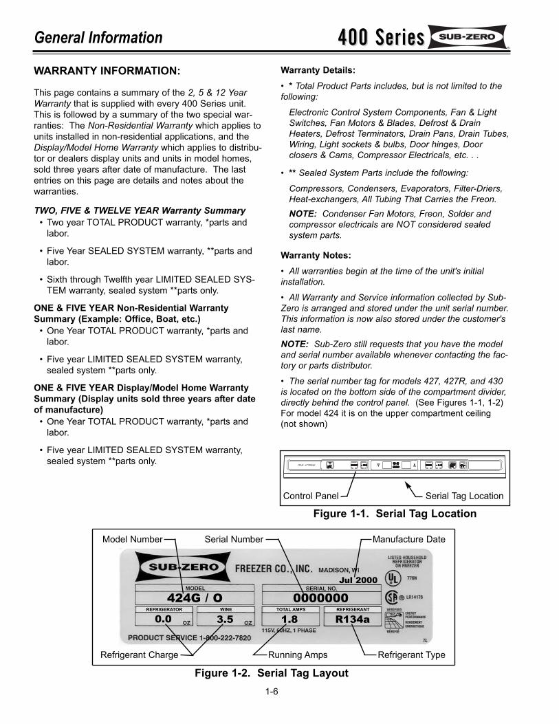
• The serial number tag for models 427, 427R, and 430is located on the bottom side of the compartment divider,directly behind the control panel. (See Figures 1-1, 1-2)For model 424 it is on the upper compartment ceiling(not shown)
Figure 1-2. Serial Tag Layout
Serial Tag LocationControl Panel
Figure 1-1. Serial Tag Location
424G / O 00000000.0 3.5 1.8 R134a
Jul 2000
Model Number Serial Number Manufacture Date
Refrigerant Charge Running Amps Refrigerant Type
TOTAL AMPS REFRIGERANTWINEREFRIGERATOR
400 Series400 Series General Information
1-7
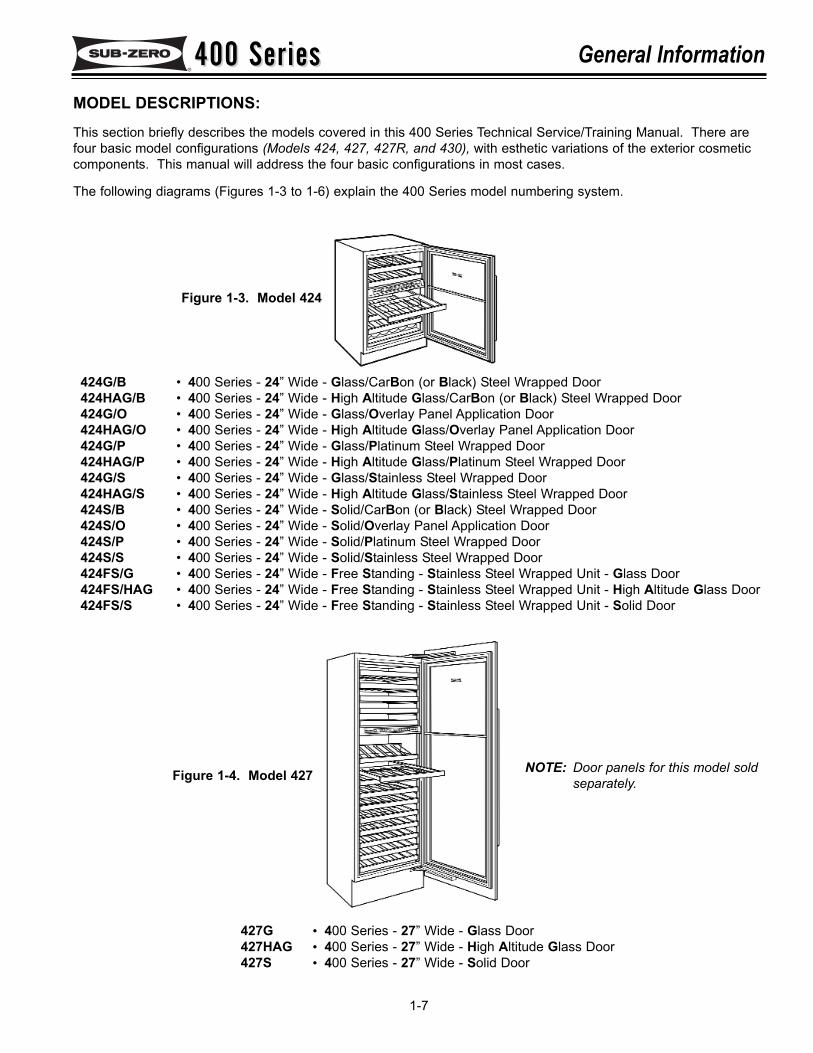
MODEL DESCRIPTIONS:This section briefly describes the models covered in this 400 Series Technical Service/Training Manual. There arefour basic model configurations (Models 424, 427, 427R, and 430), with esthetic variations of the exterior cosmeticcomponents. This manual will address the four basic configurations in most cases.
The following diagrams (Figures 1-3 to 1-6) explain the 400 Series model numbering system.
424G/B • 400 Series - 24” Wide - Glass/CarBon (or Black) Steel Wrapped Door424HAG/B • 400 Series - 24” Wide - High Altitude Glass/CarBon (or Black) Steel Wrapped Door424G/O • 400 Series - 24” Wide - Glass/Overlay Panel Application Door424HAG/O • 400 Series - 24” Wide - High Altitude Glass/Overlay Panel Application Door424G/P • 400 Series - 24” Wide - Glass/Platinum Steel Wrapped Door424HAG/P • 400 Series - 24” Wide - High Altitude Glass/Platinum Steel Wrapped Door424G/S • 400 Series - 24” Wide - Glass/Stainless Steel Wrapped Door424HAG/S • 400 Series - 24” Wide - High Altitude Glass/Stainless Steel Wrapped Door424S/B • 400 Series - 24” Wide - Solid/CarBon (or Black) Steel Wrapped Door424S/O • 400 Series - 24” Wide - Solid/Overlay Panel Application Door424S/P • 400 Series - 24” Wide - Solid/Platinum Steel Wrapped Door424S/S • 400 Series - 24” Wide - Solid/Stainless Steel Wrapped Door424FS/G • 400 Series - 24” Wide - Free Standing - Stainless Steel Wrapped Unit - Glass Door424FS/HAG • 400 Series - 24” Wide - Free Standing - Stainless Steel Wrapped Unit - High Altitude Glass Door424FS/S • 400 Series - 24” Wide - Free Standing - Stainless Steel Wrapped Unit - Solid Door
427G • 400 Series - 27” Wide - Glass Door427HAG • 400 Series - 27” Wide - High Altitude Glass Door427S • 400 Series - 27” Wide - Solid Door
Figure 1-3. Model 424
Figure 1-4. Model 427 NOTE: Door panels for this model soldseparately.
400 Series400 SeriesGeneral Information
1-8
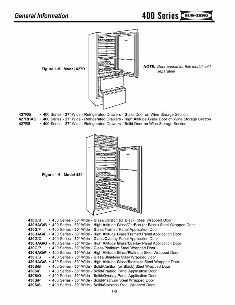
427RG • 400 Series - 27” Wide - Refrigerated Drawers - Glass Door on Wine Storage Section427RHAG • 400 Series - 27” Wide - Refrigerated Drawers - High Altitude Glass Door on Wine Storage Section427RS • 400 Series - 27” Wide - Refrigerated Drawers - Solid Door on Wine Storage Section
Figure 1-5. Model 427R
Figure 1-6. Model 430
430G/B • 400 Series - 30” Wide - Glass/CarBon (or Black) Steel Wrapped Door430HAG/B • 400 Series - 30” Wide - High Altitude Glass/CarBon (or Black) Steel Wrapped Door430G/F • 400 Series - 30” Wide - Glass/Framed Panel Application Door430HAG/F • 400 Series - 30” Wide - High Altitude Glass/Framed Panel Application Door430G/O • 400 Series - 30” Wide - Glass/Overlay Panel Application Door430HAG/O • 400 Series - 30” Wide - High Altitude Glass/Overlay Panel Application Door430G/P • 400 Series - 30” Wide - Glass/Platinum Steel Wrapped Door430HAG/P • 400 Series - 30” Wide - High Altitude Glass/Platinum Steel Wrapped Door430G/S • 400 Series - 30” Wide - Glass/Stainless Steel Wrapped Door430HAG/S • 400 Series - 30” Wide - High Altitude Glass/Stainless Steel Wrapped Door430S/B • 400 Series - 30” Wide - Solid/CarBon (or Black) Steel Wrapped Door430S/F • 400 Series - 30” Wide - Solid/Framed Panel Application Door430S/O • 400 Series - 30” Wide - Solid/Overlay Panel Application Door430S/P • 400 Series - 30” Wide - Solid/Platinum Steel Wrapped Door430S/S • 400 Series - 30” Wide - Solid/Stainless Steel Wrapped Door
NOTE: Door panels for this model soldseparately.
400 Series400 Series General Information
1-9
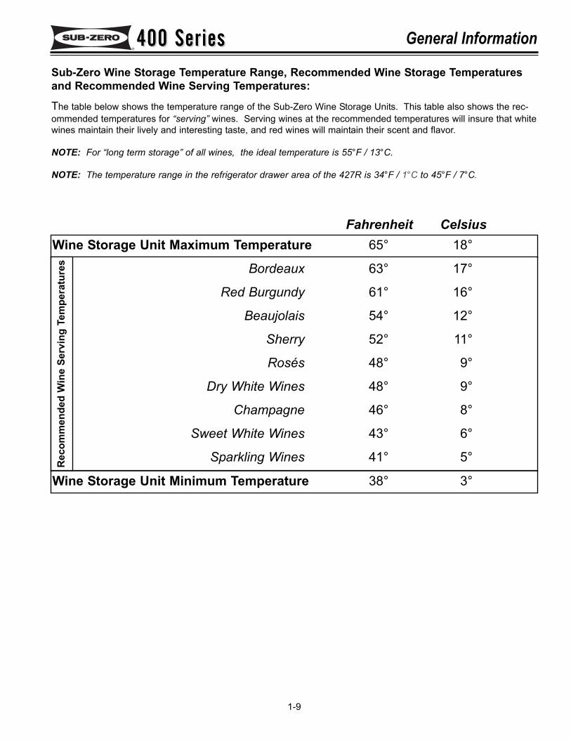
Wine Storage Unit Maximum Temperature 65° 18°
Sub-Zero Wine Storage Temperature Range, Recommended Wine Storage Temperaturesand Recommended Wine Serving Temperatures:
Bordeaux 63° 17°
Red Burgundy 61° 16°
Beaujolais 54° 12°
Sherry 52° 11°
Rosés 48° 9°
Dry White Wines 48° 9°
Champagne 46° 8°
Sweet White Wines 43° 6°
Sparkling Wines 41° 5°
Wine Storage Unit Minimum Temperature 38° 3°
Fahrenheit Celsius
The table below shows the temperature range of the Sub-Zero Wine Storage Units. This table also shows the rec-ommended temperatures for “serving” wines. Serving wines at the recommended temperatures will insure that whitewines maintain their lively and interesting taste, and red wines will maintain their scent and flavor.
NOTE: For “long term storage” of all wines, the ideal temperature is 55°F / 13°C.
NOTE: The temperature range in the refrigerator drawer area of the 427R is 34°F / 1°C to 45°F / 7°C.
Rec
omm
ende
d W
ine
Serv
ing
Tem
pera
ture
s
400 Series400 SeriesGeneral Information
1-10
400 Series400 Series Installation Information
2-1
SECTION 2
INSTALLATIONINFORMATION
INSTALLATION CONSIDERATIONS:
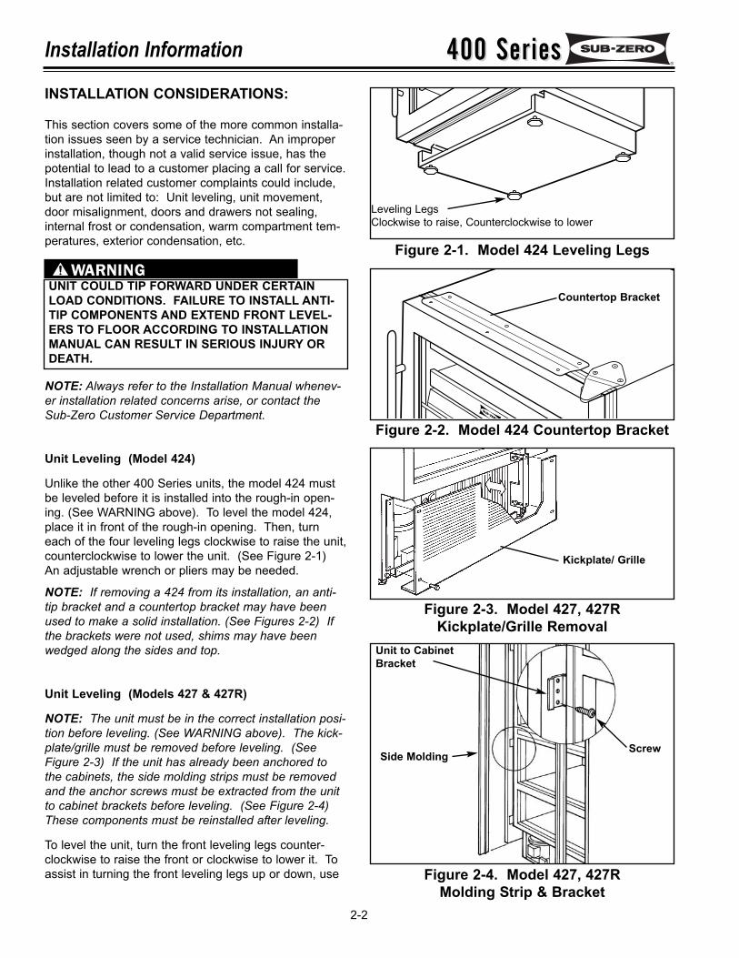
This section covers some of the more common installa-tion issues seen by a service technician. An improperinstallation, though not a valid service issue, has thepotential to lead to a customer placing a call for service.Installation related customer complaints could include,but are not limited to: Unit leveling, unit movement,door misalignment, doors and drawers not sealing,internal frost or condensation, warm compartment tem-peratures, exterior condensation, etc.
NOTE: Always refer to the Installation Manual whenev-er installation related concerns arise, or contact theSub-Zero Customer Service Department.
Unit Leveling (Model 424)
Unlike the other 400 Series units, the model 424 mustbe leveled before it is installed into the rough-in open-ing. (See WARNING above). To level the model 424,place it in front of the rough-in opening. Then, turneach of the four leveling legs clockwise to raise the unit,counterclockwise to lower the unit. (See Figure 2-1)An adjustable wrench or pliers may be needed.
NOTE: If removing a 424 from its installation, an anti-tip bracket and a countertop bracket may have beenused to make a solid installation. (See Figures 2-2) Ifthe brackets were not used, shims may have beenwedged along the sides and top.
Unit Leveling (Models 427 & 427R)
NOTE: The unit must be in the correct installation posi-tion before leveling. (See WARNING above). The kick-plate/grille must be removed before leveling. (SeeFigure 2-3) If the unit has already been anchored tothe cabinets, the side molding strips must be removedand the anchor screws must be extracted from the unitto cabinet brackets before leveling. (See Figure 2-4)These components must be reinstalled after leveling.
To level the unit, turn the front leveling legs counter-clockwise to raise the front or clockwise to lower it. Toassist in turning the front leveling legs up or down, use
400 Series400 SeriesInstallation Information
2-2
UNIT COULD TIP FORWARD UNDER CERTAINLOAD CONDITIONS. FAILURE TO INSTALL ANTI-TIP COMPONENTS AND EXTEND FRONT LEVEL-ERS TO FLOOR ACCORDING TO INSTALLATIONMANUAL CAN RESULT IN SERIOUS INJURY ORDEATH.
Figure 2-1. Model 424 Leveling Legs
Figure 2-2. Model 424 Countertop Bracket
Figure 2-4. Model 427, 427RMolding Strip & Bracket
Figure 2-3. Model 427, 427RKickplate/Grille Removal
Leveling LegsClockwise to raise, Counterclockwise to lower
Side Molding
Unit to CabinetBracket
Screw
Kickplate/ Grille
Countertop Bracket
400 Series400 Series Installation Information
2-3
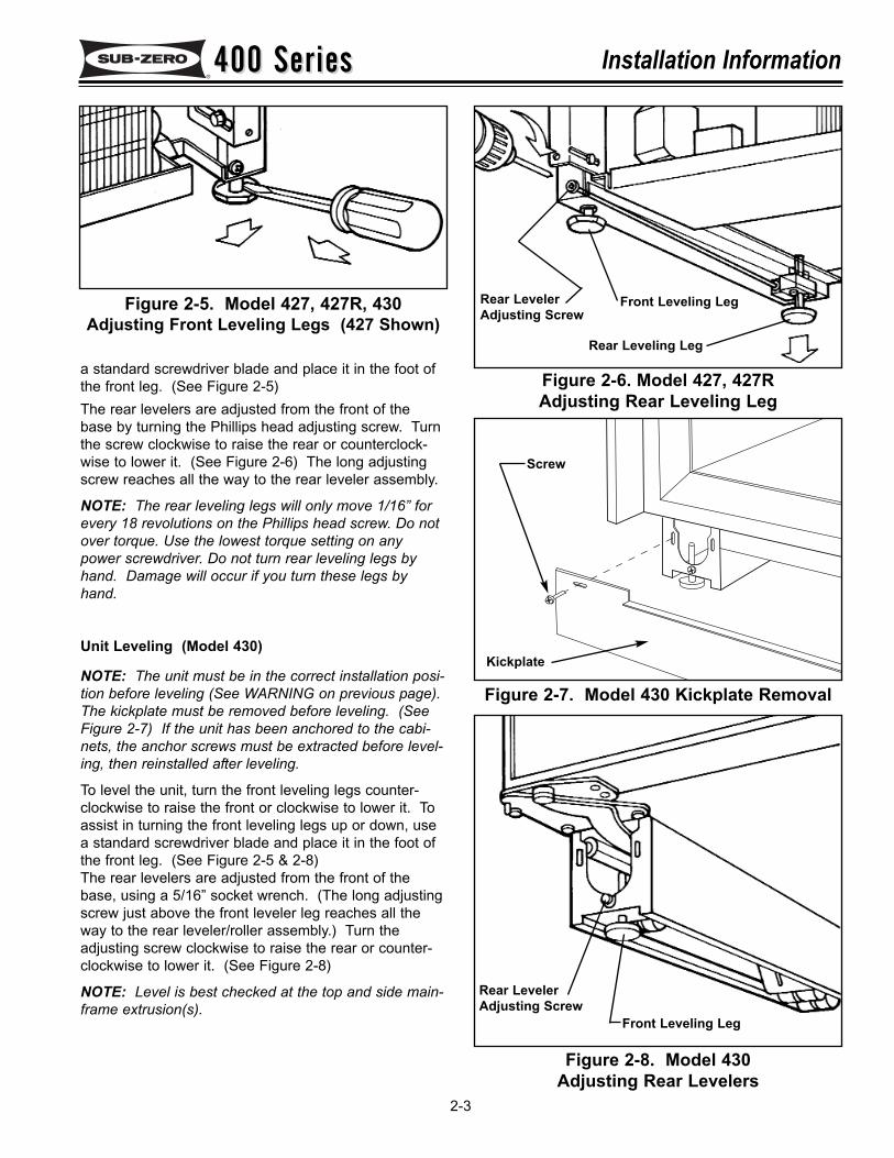
Figure 2-6. Model 427, 427RAdjusting Rear Leveling Leg
Figure 2-7. Model 430 Kickplate Removal
Figure 2-8. Model 430Adjusting Rear Levelers
Figure 2-5. Model 427, 427R, 430Adjusting Front Leveling Legs (427 Shown)
a standard screwdriver blade and place it in the foot ofthe front leg. (See Figure 2-5)The rear levelers are adjusted from the front of thebase by turning the Phillips head adjusting screw. Turnthe screw clockwise to raise the rear or counterclock-wise to lower it. (See Figure 2-6) The long adjustingscrew reaches all the way to the rear leveler assembly.
NOTE: The rear leveling legs will only move 1/16” forevery 18 revolutions on the Phillips head screw. Do notover torque. Use the lowest torque setting on anypower screwdriver. Do not turn rear leveling legs byhand. Damage will occur if you turn these legs byhand.
Unit Leveling (Model 430)
NOTE: The unit must be in the correct installation posi-tion before leveling (See WARNING on previous page).The kickplate must be removed before leveling. (SeeFigure 2-7) If the unit has been anchored to the cabi-nets, the anchor screws must be extracted before level-ing, then reinstalled after leveling.
To level the unit, turn the front leveling legs counter-clockwise to raise the front or clockwise to lower it. Toassist in turning the front leveling legs up or down, usea standard screwdriver blade and place it in the foot ofthe front leg. (See Figure 2-5 & 2-8)The rear levelers are adjusted from the front of thebase, using a 5/16” socket wrench. (The long adjustingscrew just above the front leveler leg reaches all theway to the rear leveler/roller assembly.) Turn theadjusting screw clockwise to raise the rear or counter-clockwise to lower it. (See Figure 2-8)
NOTE: Level is best checked at the top and side main-frame extrusion(s).
Kickplate
Screw
Rear LevelerAdjusting Screw
Front Leveling Leg
Rear LevelerAdjusting Screw
Front Leveling Leg
Rear Leveling Leg
400 Series400 SeriesInstallation Information
2-4
Figure 2-9. Model 424Door / Cabinet Hinge Adjustment
Figure 2-10. Model 430 Top Door Hinge
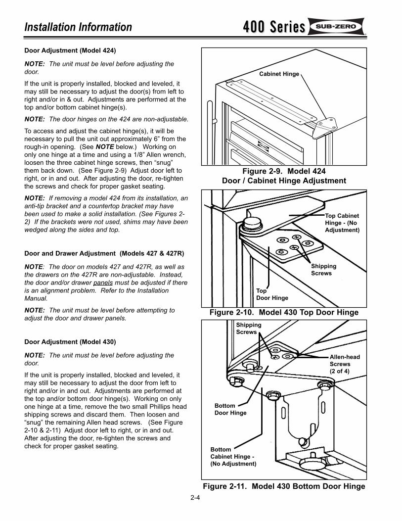
Door Adjustment (Model 424)
NOTE: The unit must be level before adjusting thedoor.
If the unit is properly installed, blocked and leveled, itmay still be necessary to adjust the door(s) from left toright and/or in & out. Adjustments are performed at thetop and/or bottom cabinet hinge(s).
NOTE: The door hinges on the 424 are non-adjustable.
To access and adjust the cabinet hinge(s), it will benecessary to pull the unit out approximately 6” from therough-in opening. (See NOTE below.) Working ononly one hinge at a time and using a 1/8” Allen wrench,loosen the three cabinet hinge screws, then “snug”them back down. (See Figure 2-9) Adjust door left toright, or in and out. After adjusting the door, re-tightenthe screws and check for proper gasket seating.
NOTE: If removing a model 424 from its installation, ananti-tip bracket and a countertop bracket may havebeen used to make a solid installation. (See Figures 2-2) If the brackets were not used, shims may have beenwedged along the sides and top.
Door and Drawer Adjustment (Models 427 & 427R)
NOTE: The door on models 427 and 427R, as well asthe drawers on the 427R are non-adjustable. Instead,the door and/or drawer panels must be adjusted if thereis an alignment problem. Refer to the InstallationManual.
NOTE: The unit must be level before attempting toadjust the door and drawer panels.
Door Adjustment (Model 430)
NOTE: The unit must be level before adjusting thedoor.
If the unit is properly installed, blocked and leveled, itmay still be necessary to adjust the door from left toright and/or in and out. Adjustments are performed atthe top and/or bottom door hinge(s). Working on onlyone hinge at a time, remove the two small Phillips headshipping screws and discard them. Then loosen and“snug” the remaining Allen head screws. (See Figure2-10 & 2-11) Adjust door left to right, or in and out.After adjusting the door, re-tighten the screws andcheck for proper gasket seating.
Figure 2-11. Model 430 Bottom Door Hinge
Cabinet Hinge
Top CabinetHinge - (NoAdjustment)
ShippingScrews
Top Door Hinge
BottomDoor Hinge
ShippingScrews
Allen-headScrews(2 of 4)
BottomCabinet Hinge - (No Adjustment)
400 Series400 Series Installation Information
2-5
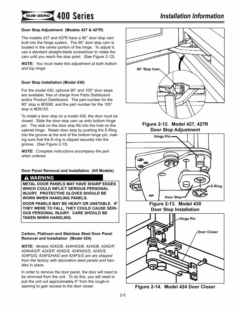
Door Stop Adjustment (Models 427 & 427R)
The models 427 and 427R have a 90° door stop cambuilt into the hinge system. The 90° door stop cam islocated in the center portion of the hinge. To adjust it,use a standard straight-blade screwdriver to rotate thecam until you reach the stop point. (See Figure 2-12)
NOTE: You must make this adjustment at both bottomand top hinge.
Door Stop Installation (Model 430)
For the model 430, optional 90° and 105° door stopsare available, free of charge from Parts Distributorsand/or Product Distributors. The part number for the90° stop is #DS90, and the part number for the 105°stop is #DS105.
To install a door stop on a model 430, the door must beclosed. Slide the door stop cam up onto bottom hingepin. The stub on the door stop fits into the hole on thecabinet hinge. Retain door stop by pushing the E-Ringinto the groove at the end of the bottom hinge pin, mak-ing sure that the E-ring is clipped securely into thegroove. (See Figure 2-13)
NOTE: Complete instructions accompany the partwhen ordered.
Figure 2-12. Model 427, 427RDoor Stop Adjustment
Figure 2-13. Model 430Door Stop Installation
E-Ring
Door Stop
Hinge Pin
METAL DOOR PANELS MAY HAVE SHARP EDGESWHICH COULD INFLICT SERIOUS PERSONALINJURY. PROTECTIVE GLOVES SHOULD BEWORN WHEN HANDLING PANELS.DOOR PANELS MAY BE HEAVY OR UNSTABLE. IFTHEY WERE TO FALL, THEY COULD CAUSE SERI-OUS PERSONAL INJURY. CARE SHOULD BETAKEN WHEN HANDLING.
Door Panel Removal and Installation (All Models)
Carbon, Platinum and Stainless Steel Door PanelRemoval and Installation (Model 424)
NOTE: Models 424G/B, 424HAG/B, 424S/B, 424G/P,424HAG/P, 424S/P, 424G/S, 424HAG/S, 424S/S,424FS/G, 424FS/HAG and 424FS/S are are shippedfrom the factory with decorative steel panels and han-dles in place.
In order to remove the door panel, the door will need tobe removed from the unit. To do this, you will need topull the unit out approximately 6” from the rough-inopening to gain access to the door closer. Figure 2-14. Model 424 Door Closer
90° Stop Cam
Door Closer
Hinge Pin
400 Series400 SeriesInstallation Information
2-6
NOTE: If removing a model 424 from its installation, ananti-tip bracket and a countertop bracket may havebeen used to make a solid installation. (See Figures 2-2) If the brackets were not used, shims may have beenwedged along the sides and top.
Remove the two mounting screws securing the doorcloser to the side of unit base. Slide the door closerdown off of the bottom door hinge pin. (See Figure 2-14)
NOTE: It may be necessary to lean the unit back slight-ly to create enough clearance between the hinge pinand the floor.
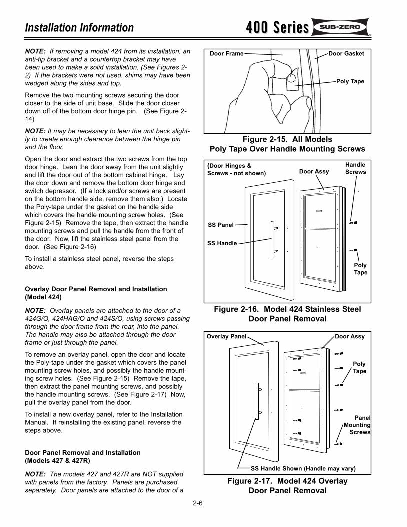
Open the door and extract the two screws from the topdoor hinge. Lean the door away from the unit slightlyand lift the door out of the bottom cabinet hinge. Laythe door down and remove the bottom door hinge andswitch depressor. (If a lock and/or screws are presenton the bottom handle side, remove them also.) Locatethe Poly-tape under the gasket on the handle sidewhich covers the handle mounting screw holes. (SeeFigure 2-15) Remove the tape, then extract the handlemounting screws and pull the handle from the front ofthe door. Now, lift the stainless steel panel from thedoor. (See Figure 2-16)
To install a stainless steel panel, reverse the stepsabove.
Overlay Door Panel Removal and Installation(Model 424)
NOTE: Overlay panels are attached to the door of a424G/O, 424HAG/O and 424S/O, using screws passingthrough the door frame from the rear, into the panel.The handle may also be attached through the doorframe or just through the panel.
To remove an overlay panel, open the door and locatethe Poly-tape under the gasket which covers the panelmounting screw holes, and possibly the handle mount-ing screw holes. (See Figure 2-15) Remove the tape,then extract the panel mounting screws, and possiblythe handle mounting screws. (See Figure 2-17) Now,pull the overlay panel from the door.
To install a new overlay panel, refer to the InstallationManual. If reinstalling the existing panel, reverse thesteps above.
Door Panel Removal and Installation(Models 427 & 427R)
NOTE: The models 427 and 427R are NOT suppliedwith panels from the factory. Panels are purchasedseparately. Door panels are attached to the door of a
Figure 2-15. All ModelsPoly Tape Over Handle Mounting Screws
Figure 2-16. Model 424 Stainless SteelDoor Panel Removal
Figure 2-17. Model 424 OverlayDoor Panel Removal
Poly Tape
Door GasketDoor Frame
HandleScrews
SS Handle
(Door Hinges &Screws - not shown)
SS Panel
PolyTape
Door Assy
Door Assy
PolyTape
PanelMounting
Screws
Overlay Panel
SS Handle Shown (Handle may vary)
400 Series400 Series Installation Information
2-7
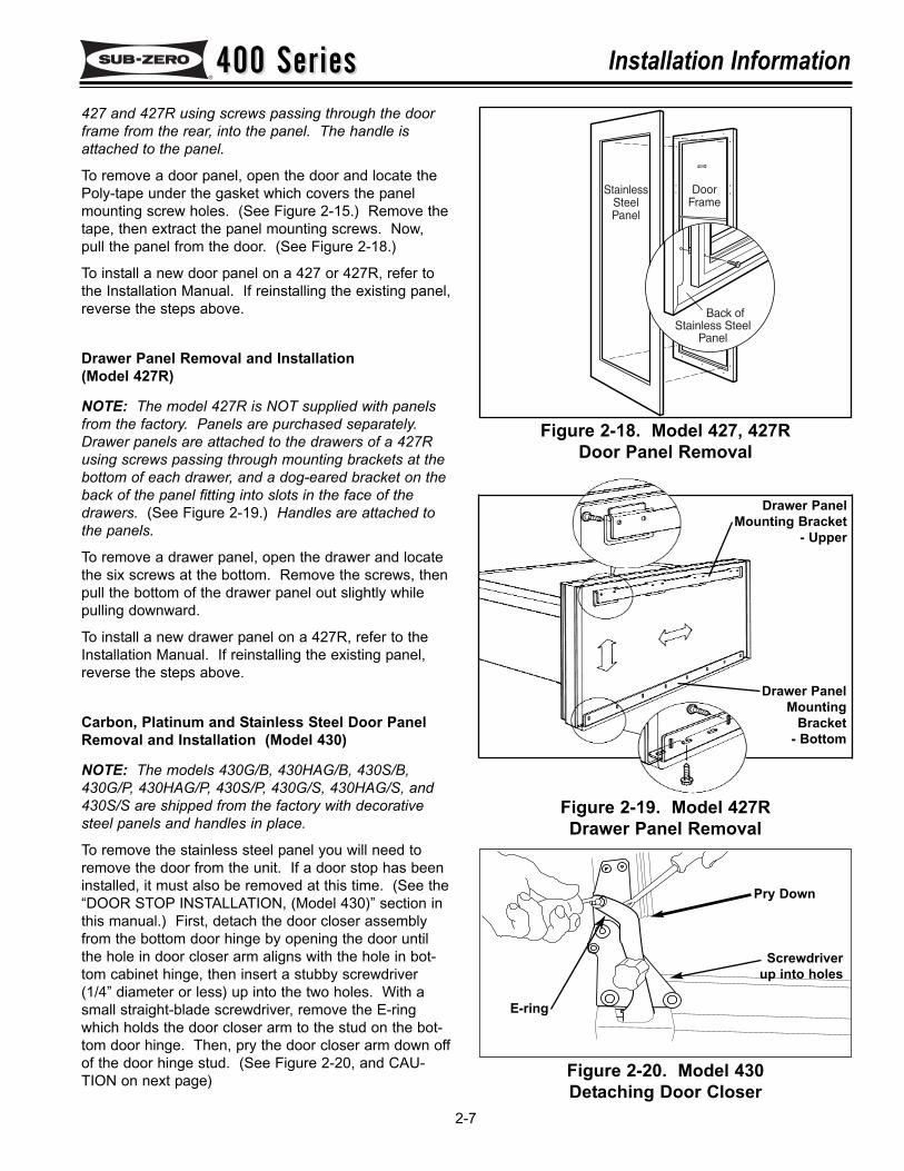
427 and 427R using screws passing through the doorframe from the rear, into the panel. The handle isattached to the panel.
To remove a door panel, open the door and locate thePoly-tape under the gasket which covers the panelmounting screw holes. (See Figure 2-15.) Remove thetape, then extract the panel mounting screws. Now,pull the panel from the door. (See Figure 2-18.)
To install a new door panel on a 427 or 427R, refer tothe Installation Manual. If reinstalling the existing panel,reverse the steps above.
Drawer Panel Removal and Installation (Model 427R)
NOTE: The model 427R is NOT supplied with panelsfrom the factory. Panels are purchased separately.Drawer panels are attached to the drawers of a 427Rusing screws passing through mounting brackets at thebottom of each drawer, and a dog-eared bracket on theback of the panel fitting into slots in the face of thedrawers. (See Figure 2-19.) Handles are attached tothe panels.
To remove a drawer panel, open the drawer and locatethe six screws at the bottom. Remove the screws, thenpull the bottom of the drawer panel out slightly whilepulling downward.
To install a new drawer panel on a 427R, refer to theInstallation Manual. If reinstalling the existing panel,reverse the steps above.
Carbon, Platinum and Stainless Steel Door PanelRemoval and Installation (Model 430)
NOTE: The models 430G/B, 430HAG/B, 430S/B,430G/P, 430HAG/P, 430S/P, 430G/S, 430HAG/S, and430S/S are shipped from the factory with decorativesteel panels and handles in place.
To remove the stainless steel panel you will need toremove the door from the unit. If a door stop has beeninstalled, it must also be removed at this time. (See the“DOOR STOP INSTALLATION, (Model 430)” section inthis manual.) First, detach the door closer assemblyfrom the bottom door hinge by opening the door untilthe hole in door closer arm aligns with the hole in bot-tom cabinet hinge, then insert a stubby screwdriver(1/4” diameter or less) up into the two holes. With asmall straight-blade screwdriver, remove the E-ringwhich holds the door closer arm to the stud on the bot-tom door hinge. Then, pry the door closer arm down offof the door hinge stud. (See Figure 2-20, and CAU-TION on next page)
Figure 2-18. Model 427, 427RDoor Panel Removal
Figure 2-19. Model 427RDrawer Panel Removal
Figure 2-20. Model 430Detaching Door Closer
Drawer PanelMounting Bracket
- Upper
Drawer PanelMounting
Bracket- Bottom
Pry Down
Screwdriverup into holes
E-ring
400 Series400 SeriesInstallation Information
2-8
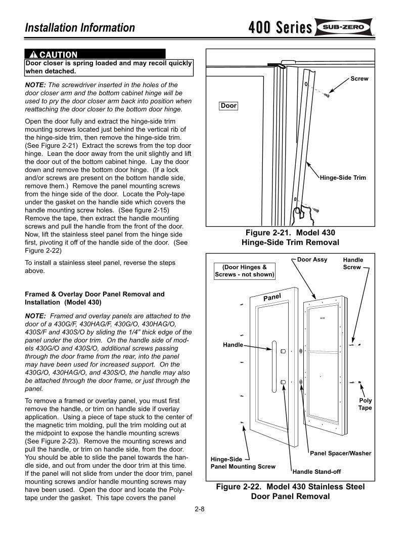
NOTE: The screwdriver inserted in the holes of thedoor closer arm and the bottom cabinet hinge will beused to pry the door closer arm back into position whenreattaching the door closer to the bottom door hinge.
Open the door fully and extract the hinge-side trimmounting screws located just behind the vertical rib ofthe hinge-side trim, then remove the hinge-side trim.(See Figure 2-21) Extract the screws from the top doorhinge. Lean the door away from the unit slightly and liftthe door out of the bottom cabinet hinge. Lay the doordown and remove the bottom door hinge. (If a lockand/or screws are present on the bottom handle side,remove them.) Remove the panel mounting screwsfrom the hinge side of the door. Locate the Poly-tapeunder the gasket on the handle side which covers thehandle mounting screw holes. (See figure 2-15)Remove the tape, then extract the handle mountingscrews and pull the handle from the front of the door.Now, lift the stainless steel panel from the hinge sidefirst, pivoting it off of the handle side of the door. (SeeFigure 2-22)
To install a stainless steel panel, reverse the stepsabove.
Framed & Overlay Door Panel Removal andInstallation (Model 430)
NOTE: Framed and overlay panels are attached to thedoor of a 430G/F, 430HAG/F, 430G/O, 430HAG/O,430S/F and 430S/O by sliding the 1/4” thick edge of thepanel under the door trim. On the handle side of mod-els 430G/O and 430S/O, additional screws passingthrough the door frame from the rear, into the panelmay have been used for increased support. On the430G/O, 430HAG/O, and 430S/O, the handle may alsobe attached through the door frame, or just through thepanel.
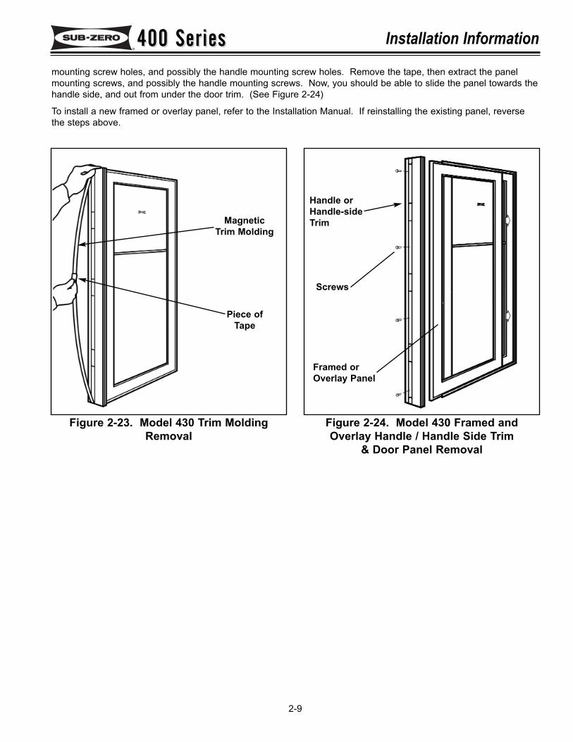
To remove a framed or overlay panel, you must firstremove the handle, or trim on handle side if overlayapplication. Using a piece of tape stuck to the center ofthe magnetic trim molding, pull the trim molding out atthe midpoint to expose the handle mounting screws(See Figure 2-23). Remove the mounting screws andpull the handle, or trim on handle side, from the door.You should be able to slide the panel towards the han-dle side, and out from under the door trim at this time.If the panel will not slide from under the door trim, panelmounting screws and/or handle mounting screws mayhave been used. Open the door and locate the Poly-tape under the gasket. This tape covers the panel
Figure 2-21. Model 430Hinge-Side Trim Removal
Figure 2-22. Model 430 Stainless SteelDoor Panel Removal
Hinge-Side Trim
Screw
Door
Panel
PolyTape
Door Assy HandleScrew(Door Hinges &
Screws - not shown)
Handle
Door closer is spring loaded and may recoil quicklywhen detached.
Hinge-SidePanel Mounting Screw
Handle Stand-off
Panel Spacer/Washer
400 Series400 Series Installation Information
2-9
Figure 2-23. Model 430 Trim MoldingRemoval
Figure 2-24. Model 430 Framed andOverlay Handle / Handle Side Trim
& Door Panel Removal
mounting screw holes, and possibly the handle mounting screw holes. Remove the tape, then extract the panelmounting screws, and possibly the handle mounting screws. Now, you should be able to slide the panel towards thehandle side, and out from under the door trim. (See Figure 2-24)
To install a new framed or overlay panel, refer to the Installation Manual. If reinstalling the existing panel, reversethe steps above.
MagneticTrim Molding
Handle orHandle-sideTrim
Screws
Piece ofTape
Framed orOverlay Panel
400 Series400 SeriesInstallation Information Notes
2-10
400 Series400 Series Electronic Control System Information
3-1
SECTION 3
ELECTRONIC CONTROLSYSTEM INFORMATION
400 Series400 SeriesElectronic Control System Information
3-2
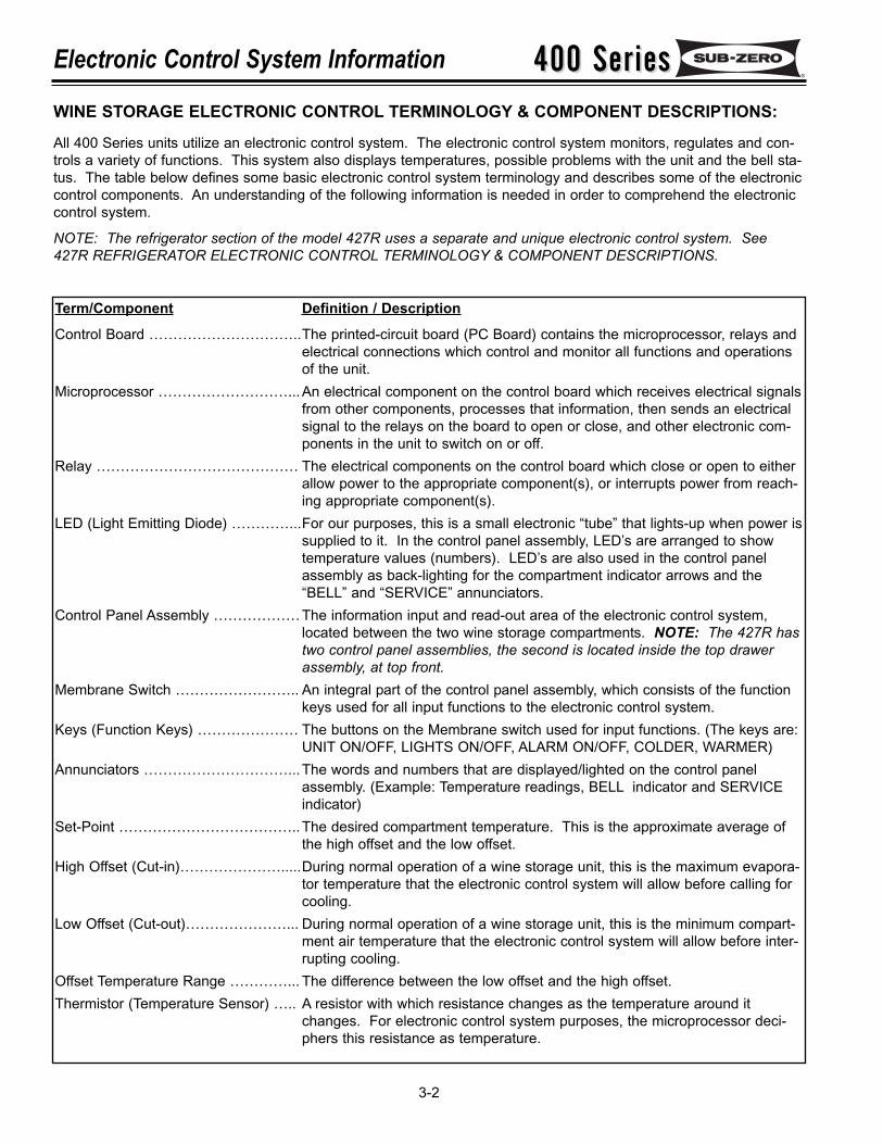
Term/Component Definition / Description
Control Board …………………………..The printed-circuit board (PC Board) contains the microprocessor, relays andelectrical connections which control and monitor all functions and operationsof the unit.
Microprocessor ………………………...An electrical component on the control board which receives electrical signalsfrom other components, processes that information, then sends an electricalsignal to the relays on the board to open or close, and other electronic com-ponents in the unit to switch on or off.
Relay …………………………………… The electrical components on the control board which close or open to eitherallow power to the appropriate component(s), or interrupts power from reach-ing appropriate component(s).
LED (Light Emitting Diode) …………...For our purposes, this is a small electronic “tube” that lights-up when power issupplied to it. In the control panel assembly, LED’s are arranged to showtemperature values (numbers). LED’s are also used in the control panelassembly as back-lighting for the compartment indicator arrows and the“BELL” and “SERVICE” annunciators.
Control Panel Assembly ………………The information input and read-out area of the electronic control system,located between the two wine storage compartments. NOTE: The 427R hastwo control panel assemblies, the second is located inside the top drawerassembly, at top front.
Membrane Switch …………………….. An integral part of the control panel assembly, which consists of the functionkeys used for all input functions to the electronic control system.
Keys (Function Keys) ………………… The buttons on the Membrane switch used for input functions. (The keys are:UNIT ON/OFF, LIGHTS ON/OFF, ALARM ON/OFF, COLDER, WARMER)
Annunciators …………………………...The words and numbers that are displayed/lighted on the control panelassembly. (Example: Temperature readings, BELL indicator and SERVICEindicator)
Set-Point ………………………………..The desired compartment temperature. This is the approximate average ofthe high offset and the low offset.
High Offset (Cut-in)………………….....During normal operation of a wine storage unit, this is the maximum evapora-tor temperature that the electronic control system will allow before calling forcooling.
Low Offset (Cut-out)…………………... During normal operation of a wine storage unit, this is the minimum compart-ment air temperature that the electronic control system will allow before inter-rupting cooling.
Offset Temperature Range …………... The difference between the low offset and the high offset.Thermistor (Temperature Sensor) ….. A resistor with which resistance changes as the temperature around it
changes. For electronic control system purposes, the microprocessor deci-phers this resistance as temperature.
WINE STORAGE ELECTRONIC CONTROL TERMINOLOGY & COMPONENT DESCRIPTIONS:
All 400 Series units utilize an electronic control system. The electronic control system monitors, regulates and con-trols a variety of functions. This system also displays temperatures, possible problems with the unit and the bell sta-tus. The table below defines some basic electronic control system terminology and describes some of the electroniccontrol components. An understanding of the following information is needed in order to comprehend the electroniccontrol system.
NOTE: The refrigerator section of the model 427R uses a separate and unique electronic control system. See427R REFRIGERATOR ELECTRONIC CONTROL TERMINOLOGY & COMPONENT DESCRIPTIONS.
400 Series400 Series Electronic Control System Information
3-3
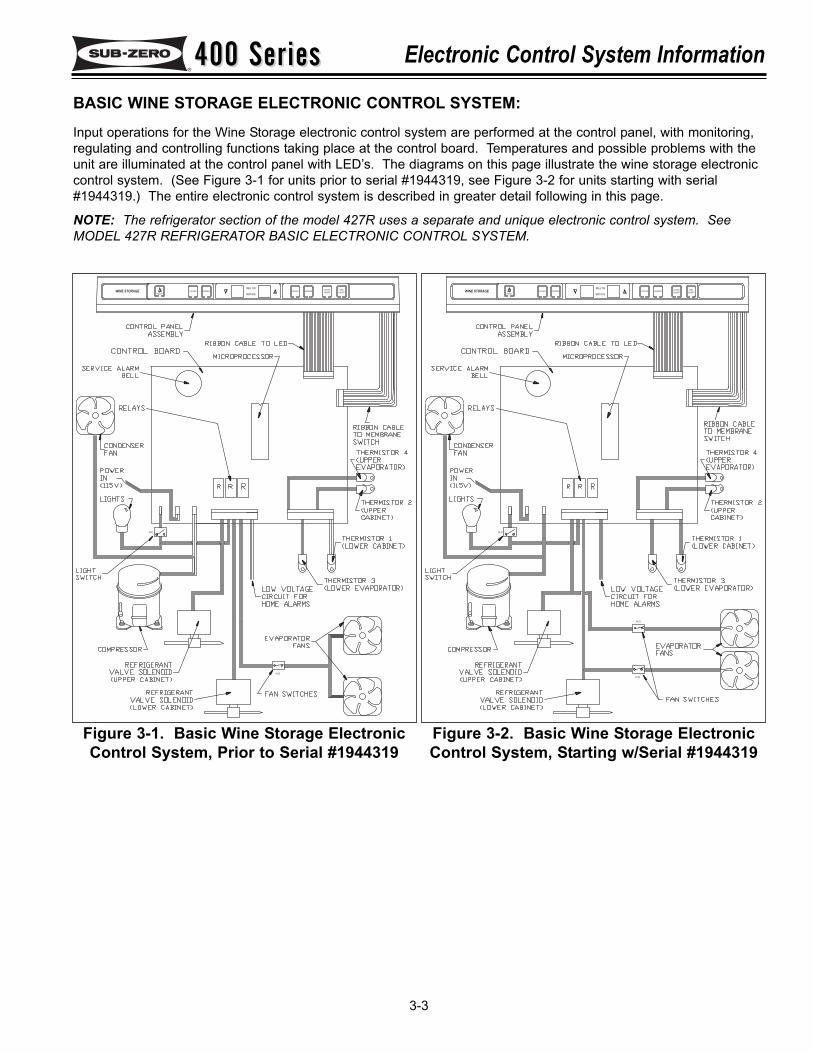
Figure 3-1. Basic Wine Storage ElectronicControl System, Prior to Serial #1944319
BASIC WINE STORAGE ELECTRONIC CONTROL SYSTEM:Input operations for the Wine Storage electronic control system are performed at the control panel, with monitoring,regulating and controlling functions taking place at the control board. Temperatures and possible problems with theunit are illuminated at the control panel with LED’s. The diagrams on this page illustrate the wine storage electroniccontrol system. (See Figure 3-1 for units prior to serial #1944319, see Figure 3-2 for units starting with serial#1944319.) The entire electronic control system is described in greater detail following in this page.
NOTE: The refrigerator section of the model 427R uses a separate and unique electronic control system. SeeMODEL 427R REFRIGERATOR BASIC ELECTRONIC CONTROL SYSTEM.
WINE STORAGE COLDER WARMER COLDER WARMER
ON/OFF
LIGHTS
ON/OFF
UNIT
ON/OFF
BELL ON
SERVICE
N.C.
N.O.
Figure 3-2. Basic Wine Storage ElectronicControl System, Starting w/Serial #1944319
WINE STORAGE COLDER WARMER COLDER WARMER
ON/OFF
LIGHTS
ON/OFF
UNIT
ON/OFF
BELL ON
SERVICE
N.C.
N.O.
N.O.
400 Series400 SeriesElectronic Control System Information
3-4
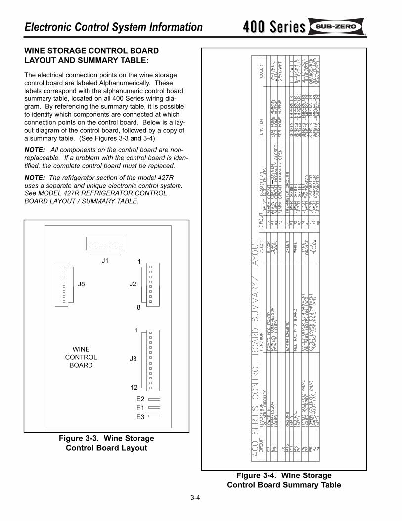
Figure 3-3. Wine Storage Control Board Layout
Figure 3-4. Wine Storage Control Board Summary Table
WINECONTROL
BOARD
J1
J8 J2
J3
1
12
E2E1E3
1
8
WINE STORAGE CONTROL BOARDLAYOUT AND SUMMARY TABLE:The electrical connection points on the wine storagecontrol board are labeled Alphanumerically. Theselabels correspond with the alphanumeric control boardsummary table, located on all 400 Series wiring dia-gram. By referencing the summary table, it is possibleto identify which components are connected at whichconnection points on the control board. Below is a lay-out diagram of the control board, followed by a copy ofa summary table. (See Figures 3-3 and 3-4)
NOTE: All components on the control board are non-replaceable. If a problem with the control board is iden-tified, the complete control board must be replaced.
NOTE: The refrigerator section of the model 427Ruses a separate and unique electronic control system.See MODEL 427R REFRIGERATOR CONTROLBOARD LAYOUT / SUMMARY TABLE.
400 Series400 Series Electronic Control System Information
3-5
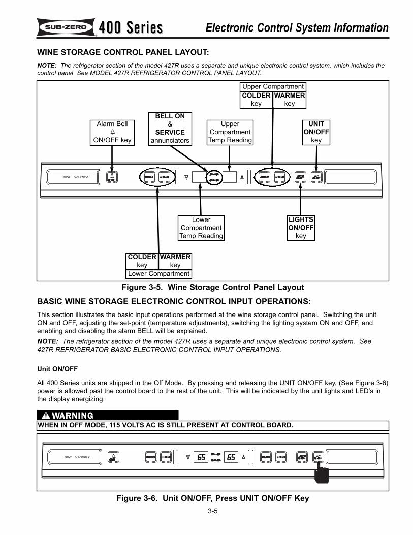
WINE STORAGE CONTROL PANEL LAYOUT:NOTE: The refrigerator section of the model 427R uses a separate and unique electronic control system, which includes thecontrol panel See MODEL 427R REFRIGERATOR CONTROL PANEL LAYOUT.
Figure 3-5. Wine Storage Control Panel Layout
WHEN IN OFF MODE, 115 VOLTS AC IS STILL PRESENT AT CONTROL BOARD.
Figure 3-6. Unit ON/OFF, Press UNIT ON/OFF Key
BELL ON&
SERVICEannunciators
UpperCompartmentTemp Reading
LowerCompartmentTemp Reading
Upper Compartment COLDER
keyWARMER
key
Lower Compartment
COLDERkey
WARMERkey
Alarm Bell
ON/OFF key
UNITON/OFF
key
LIGHTSON/OFF
key
6655 6655
BASIC WINE STORAGE ELECTRONIC CONTROL INPUT OPERATIONS:This section illustrates the basic input operations performed at the wine storage control panel. Switching the unitON and OFF, adjusting the set-point (temperature adjustments), switching the lighting system ON and OFF, andenabling and disabling the alarm BELL will be explained.NOTE: The refrigerator section of the model 427R uses a separate and unique electronic control system. See427R REFRIGERATOR BASIC ELECTRONIC CONTROL INPUT OPERATIONS.
Unit ON/OFF
All 400 Series units are shipped in the Off Mode. By pressing and releasing the UNIT ON/OFF key, (See Figure 3-6)power is allowed past the control board to the rest of the unit. This will be indicated by the unit lights and LED’s inthe display energizing.
400 Series400 SeriesElectronic Control System Information
3-6
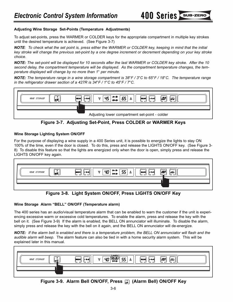
Adjusting Wine Storage Set-Points (Temperature Adjustments)
To adjust set-points, press the WARMER or COLDER keys for the appropriate compartment in multiple key strokesuntil the desired temperature is achieved. (See Figure 3-7) NOTE: To check what the set point is, press either the WARMER or COLDER key, keeping in mind that the initialkey stroke will change the previous set-point by a one degree increment or decrement depending on your key strokechoice.NOTE: The set-point will be displayed for 10 seconds after the last WARMER or COLDER key stroke. After the 10second delay, the compartment temperature will be displayed. As the compartment temperature changes, the tem-perature displayed will change by no more than 1° per minute.NOTE: The temperature range in a wine storage compartment is 38°F / 3°C to 65°F / 18°C. The temperature rangein the refrigerator drawer section of a 427R is 34°F / 1°C to 45°F / 7°C.
Figure 3-7. Adjusting Set-Point, Press COLDER or WARMER Keys
Wine Storage Lighting System ON/OFF
For the purpose of displaying a wine supply in a 400 Series unit, it is possible to energize the lights to stay ON100% of the time, even if the door is closed. To do this, press and release the LIGHTS ON/OFF key. (See Figure 3-8) To disable this feature so that the lights are energized only when the door is open, simply press and release theLIGHTS ON/OFF key again.
Wine Storage Alarm “BELL” ON/OFF (Temperature alarm)
The 400 series has an audio/visual temperature alarm that can be enabled to warn the customer if the unit is experi-encing excessive warm or excessive cold temperatures. To enable the alarm, press and release the key with thebell on it. (See Figure 3-9) If the alarm is enabled, the BELL ON annunciator will illuminate. To disable the alarm,simply press and release the key with the bell on it again, and the BELL ON annunciator will de-energize.
NOTE: If the alarm bell is enabled and there is a temperature problem, the BELL ON annunciator will flash and theaudible alarm will beep. The alarm feature can also be tied in with a home security alarm system. This will beexplained later in this manual.
Figure 3-8. Light System ON/OFF, Press LIGHTS ON/OFF Key
Figure 3-9. Alarm Bell ON/OFF, Press
Adjusting lower compartment set-point - colder
66554455
4400 5555
4400 5555
(Alarm Bell) ON/OFF Key
400 Series400 Series Electronic Control System Information
3-7
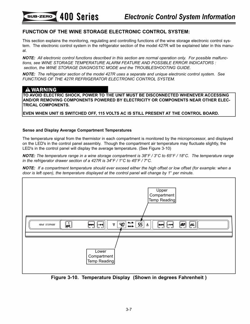
FUNCTION OF THE WINE STORAGE ELECTRONIC CONTROL SYSTEM:This section explains the monitoring, regulating and controlling functions of the wine storage electronic control sys-tem. The electronic control system in the refrigerator section of the model 427R will be explained later in this manu-al.
NOTE: All electronic control functions described in this section are normal operation only. For possible malfunc-tions, see WINE STORAGE TEMPERATURE ALARM FEATURE AND POSSIBLE ERROR INDICATORS :section, the WINE STORAGE DIAGNOSTIC MODE and the TROUBLESHOOTING GUIDE.
NOTE: The refrigerator section of the model 427R uses a separate and unique electronic control system. SeeFUNCTIONS OF THE 427R REFRIGERATOR ELECTRONIC CONTROL SYSTEM.
TO AVOID ELECTRIC SHOCK, POWER TO THE UNIT MUST BE DISCONNECTED WHENEVER ACCESSINGAND/OR REMOVING COMPONENTS POWERED BY ELECTRICITY OR COMPONENTS NEAR OTHER ELEC-TRICAL COMPONENTS.
EVEN WHEN UNIT IS SWITCHED OFF, 115 VOLTS AC IS STILL PRESENT AT THE CONTROL BOARD.
Sense and Display Average Compartment Temperatures
The temperature signal from the thermistor in each compartment is monitored by the microprocessor, and displayedon the LED's in the control panel assembly. Though the compartment air temperature may fluctuate slightly, theLED's in the control panel will display the average temperature. (See Figure 3-10)
NOTE: The temperature range in a wine storage compartment is 38°F / 3°C to 65°F / 18°C. The temperature rangein the refrigerator drawer section of a 427R is 34°F / 1°C to 45°F / 7°C.
NOTE: If a compartment temperature should ever exceed either the high offset or low offset (for example: when adoor is left open), the temperature displayed at the control panel will change by 1° per minute.
Figure 3-10. Temperature Display (Shown in degrees Fahrenheit )
4400 5555
UpperCompartmentTemp Reading
LowerCompartmentTemp Reading
400 Series400 SeriesElectronic Control System Information
3-8
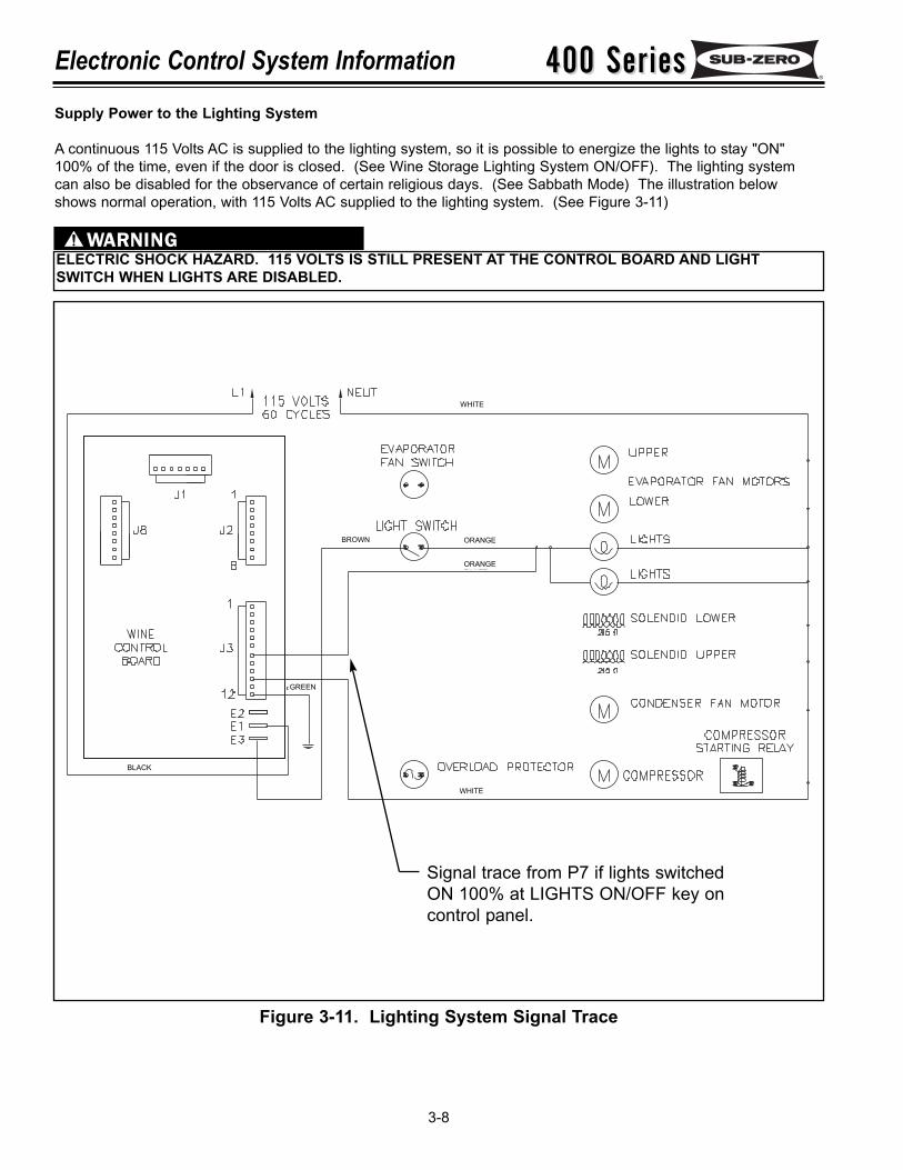
Supply Power to the Lighting System
A continuous 115 Volts AC is supplied to the lighting system, so it is possible to energize the lights to stay "ON"100% of the time, even if the door is closed. (See Wine Storage Lighting System ON/OFF). The lighting systemcan also be disabled for the observance of certain religious days. (See Sabbath Mode) The illustration belowshows normal operation, with 115 Volts AC supplied to the lighting system. (See Figure 3-11)
ELECTRIC SHOCK HAZARD. 115 VOLTS IS STILL PRESENT AT THE CONTROL BOARD AND LIGHTSWITCH WHEN LIGHTS ARE DISABLED.
Figure 3-11. Lighting System Signal Trace
Signal trace from P7 if lights switchedON 100% at LIGHTS ON/OFF key oncontrol panel.
BLACK
WHITE
WHITE
ORANGEBROWN
ORANGE
GREEN
400 Series400 Series Electronic Control System Information
3-9
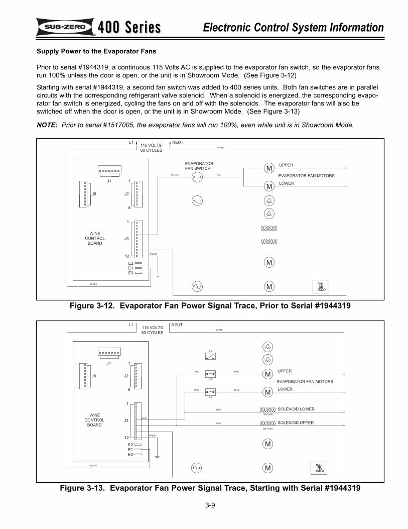
Supply Power to the Evaporator Fans
Prior to serial #1944319, a continuous 115 Volts AC is supplied to the evaporator fan switch, so the evaporator fansrun 100% unless the door is open, or the unit is in Showroom Mode. (See Figure 3-12)
Starting with serial #1944319, a second fan switch was added to 400 series units. Both fan switches are in parallelcircuits with the corresponding refrigerant valve solenoid. When a solenoid is energized, the corresponding evapo-rator fan switch is energized, cycling the fans on and off with the solenoids. The evaporator fans will also beswitched off when the door is open, or the unit is in Showroom Mode. (See Figure 3-13)
NOTE: Prior to serial #1517005, the evaporator fans will run 100%, even while unit is in Showroom Mode.
MUPPER
WHITE
NEUT
EVAPORATOR
FAN SWITCH
MLOWER
EVAPORATOR FAN MOTORS
M
M
REDYELLOW
L1
1
J2
J1
8
1
J8
WINE
E2
E1
12
E3
BLACK
BOARD
CONTROL J3
GREEN
115 VOLTS
60 CYCLES
Figure 3-12. Evaporator Fan Power Signal Trace, Prior to Serial #1944319
60 CYCLES
115 VOLTS
GREEN
J3CONTROL
BOARD
BLACK
E3
12
E1
E2
WINE
J8
1
8
J1
J2
1
L1
PINK
PINK
BLUE
PINK
SOLENOID UPPER
295 OHMS
EVAPORATOR FAN MOTORS
SOLENOID LOWER
295 OHMS
LOWER
NEUT
WHITE
UPPER
BLUE BLUE
N.O.
N.O.
N.C.
BLUE
M
M
M
M
Figure 3-13. Evaporator Fan Power Signal Trace, Starting with Serial #1944319
400 Series400 SeriesElectronic Control System Information
3-10
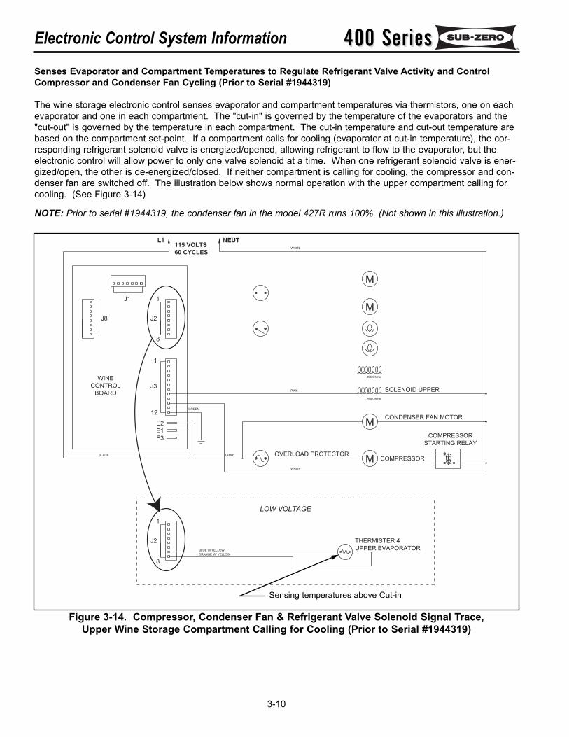
Senses Evaporator and Compartment Temperatures to Regulate Refrigerant Valve Activity and ControlCompressor and Condenser Fan Cycling (Prior to Serial #1944319)
The wine storage electronic control senses evaporator and compartment temperatures via thermistors, one on eachevaporator and one in each compartment. The "cut-in" is governed by the temperature of the evaporators and the"cut-out" is governed by the temperature in each compartment. The cut-in temperature and cut-out temperature arebased on the compartment set-point. If a compartment calls for cooling (evaporator at cut-in temperature), the cor-responding refrigerant solenoid valve is energized/opened, allowing refrigerant to flow to the evaporator, but theelectronic control will allow power to only one valve solenoid at a time. When one refrigerant solenoid valve is ener-gized/open, the other is de-energized/closed. If neither compartment is calling for cooling, the compressor and con-denser fan are switched off. The illustration below shows normal operation with the upper compartment calling forcooling. (See Figure 3-14)
NOTE: Prior to serial #1944319, the condenser fan in the model 427R runs 100%. (Not shown in this illustration.)
M
WHITE
NEUT
M
295 Ohms
COMPRESSOR
295 Ohms
M
M COMPRESSOR
CONDENSER FAN MOTOR
SOLENOID UPPER
STARTING RELAY
PINK
WHITE
GRAY OVERLOAD PROTECTOR
L1
1
J2
J1
8
1
J8
WINE
E2
E1
12
E3
BLACK
BOARD
CONTROL J3
GREEN
115 VOLTS
60 CYCLES
UPPER EVAPORATOR
THERMISTER 4
1
ORANGE W/ YELLOW
8
J2
LOW VOLTAGE
BLUE W/YELLOW
Figure 3-14. Compressor, Condenser Fan & Refrigerant Valve Solenoid Signal Trace, Upper Wine Storage Compartment Calling for Cooling (Prior to Serial #1944319)
Sensing temperatures above Cut-in
400 Series400 Series Electronic Control System Information
3-11
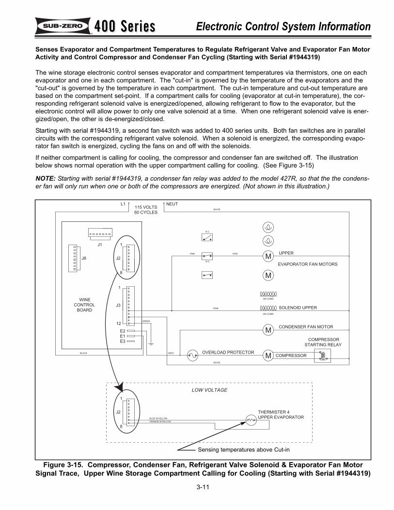
Senses Evaporator and Compartment Temperatures to Regulate Refrigerant Valve and Evaporator Fan MotorActivity and Control Compressor and Condenser Fan Cycling (Starting with Serial #1944319)
The wine storage electronic control senses evaporator and compartment temperatures via thermistors, one on eachevaporator and one in each compartment. The "cut-in" is governed by the temperature of the evaporators and the"cut-out" is governed by the temperature in each compartment. The cut-in temperature and cut-out temperature arebased on the compartment set-point. If a compartment calls for cooling (evaporator at cut-in temperature), the cor-responding refrigerant solenoid valve is energized/opened, allowing refrigerant to flow to the evaporator, but theelectronic control will allow power to only one valve solenoid at a time. When one refrigerant solenoid valve is ener-gized/open, the other is de-energized/closed.
Starting with serial #1944319, a second fan switch was added to 400 series units. Both fan switches are in parallelcircuits with the corresponding refrigerant valve solenoid. When a solenoid is energized, the corresponding evapo-rator fan switch is energized, cycling the fans on and off with the solenoids.
If neither compartment is calling for cooling, the compressor and condenser fan are switched off. The illustrationbelow shows normal operation with the upper compartment calling for cooling. (See Figure 3-15)
NOTE: Starting with serial #1944319, a condenser fan relay was added to the model 427R, so that the the condens-er fan will only run when one or both of the compressors are energized. (Not shown in this illustration.)
60 CYCLES
115 VOLTS
GREEN
J3CONTROL
BOARD
BLACK
E3
12
E1
E2
WINE
J8
1
8
J1
J2
1
L1
OVERLOAD PROTECTORGRAY
WHITE
PINK
PINK PINK
STARTING RELAY
SOLENOID UPPER
CONDENSER FAN MOTOR
COMPRESSOR
295 OHMS
COMPRESSOR
EVAPORATOR FAN MOTORS
295 OHMS
NEUT
WHITE
UPPER
N.O.
N.C.
M
M
M
M
LOW VOLTAGE
ORANGE W/YELLOW
UPPER EVAPORATOR
THERMISTER 4J2
1
8
BLUE W/YELLOW
Figure 3-15. Compressor, Condenser Fan, Refrigerant Valve Solenoid & Evaporator Fan MotorSignal Trace, Upper Wine Storage Compartment Calling for Cooling (Starting with Serial #1944319)
Sensing temperatures above Cut-in
400 Series400 SeriesElectronic Control System Information
3-12
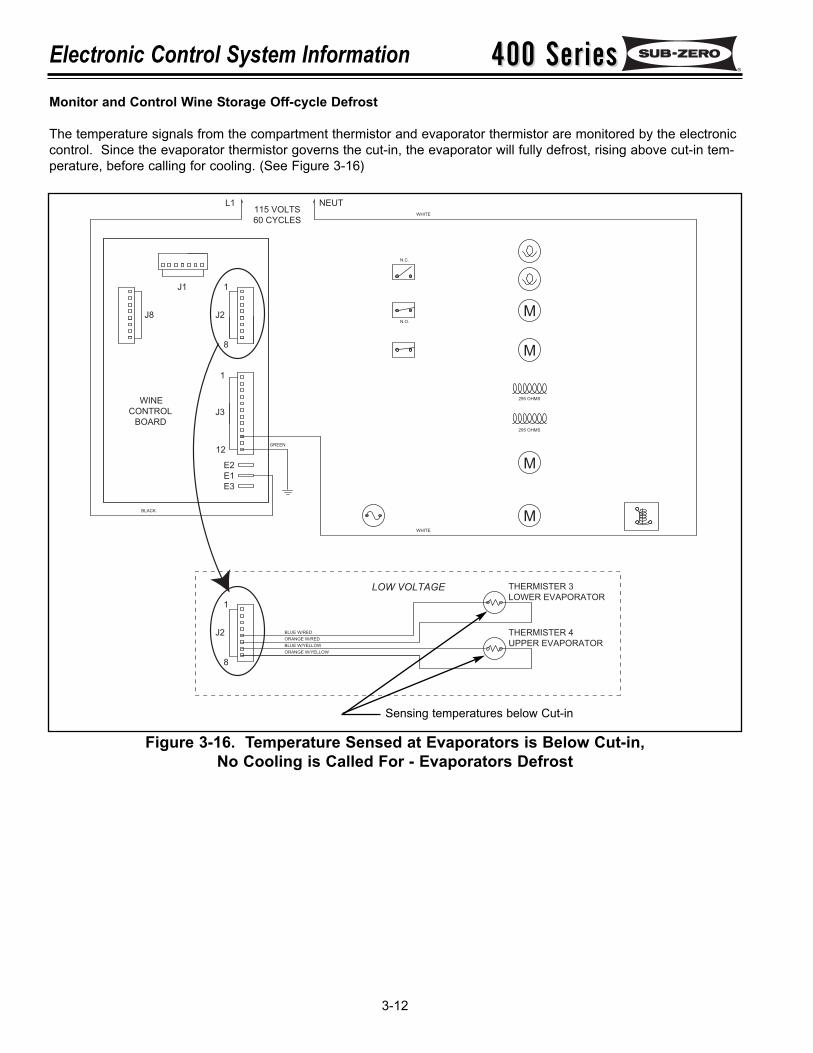
Monitor and Control Wine Storage Off-cycle Defrost
The temperature signals from the compartment thermistor and evaporator thermistor are monitored by the electroniccontrol. Since the evaporator thermistor governs the cut-in, the evaporator will fully defrost, rising above cut-in tem-perature, before calling for cooling. (See Figure 3-16)
60 CYCLES
115 VOLTS
GREEN
J3CONTROL
BOARD
BLACK
E3
12
E1
E2
WINE
J8
1
8
J1
J2
1
L1
WHITE
295 OHMS
295 OHMS
NEUT
WHITE
N.O.
N.C.
M
M
M
M
LOW VOLTAGE
ORANGE W/YELLOW
UPPER EVAPORATOR
THERMISTER 4J2
1
8
BLUE W/RED
ORANGE W/RED
BLUE W/YELLOW
LOWER EVAPORATOR
THERMISTER 3
Figure 3-16. Temperature Sensed at Evaporators is Below Cut-in, No Cooling is Called For - Evaporators Defrost
Sensing temperatures below Cut-in
400 Series400 Series Electronic Control System Information
3-13
5555 4400
°°CC
UNIQUE WINE STORAGE ELECTRONIC CONTROL INPUT OPERATIONS:This section illustrates unique wine storage electronic control input operations performed at the control panel, thatyou would not expect a customer to perform every day. This section explains the Temperature Units SelectionMode, Sabbath Mode and Showroom Mode.NOTE: The refrigerator section of the model 427R uses a separate and unique electronic control system. See427R REFRIGERATOR SECTION, UNIQUE ELECTRONIC CONTROL INPUT OPERATIONS.
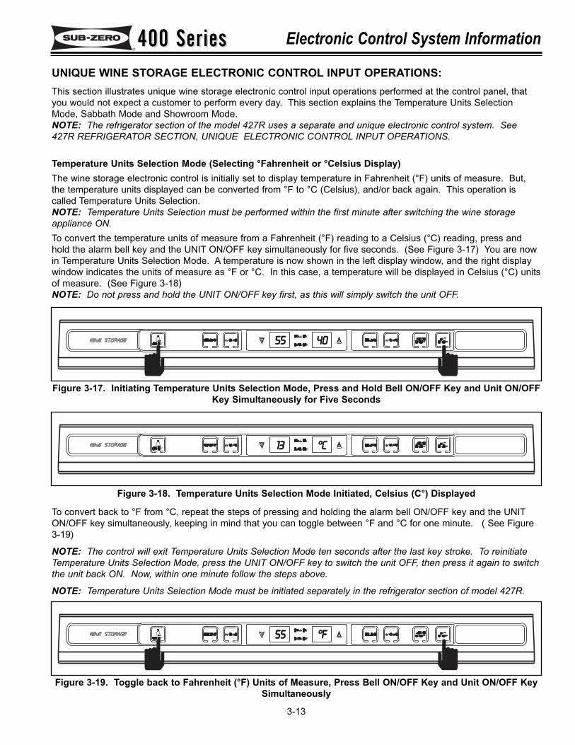
Temperature Units Selection Mode (Selecting °Fahrenheit or °Celsius Display)The wine storage electronic control is initially set to display temperature in Fahrenheit (°F) units of measure. But,the temperature units displayed can be converted from °F to °C (Celsius), and/or back again. This operation iscalled Temperature Units Selection.NOTE: Temperature Units Selection must be performed within the first minute after switching the wine storageappliance ON.To convert the temperature units of measure from a Fahrenheit (°F) reading to a Celsius (°C) reading, press andhold the alarm bell key and the UNIT ON/OFF key simultaneously for five seconds. (See Figure 3-17) You are nowin Temperature Units Selection Mode. A temperature is now shown in the left display window, and the right displaywindow indicates the units of measure as °F or °C. In this case, a temperature will be displayed in Celsius (°C) unitsof measure. (See Figure 3-18)NOTE: Do not press and hold the UNIT ON/OFF key first, as this will simply switch the unit OFF.
To convert back to °F from °C, repeat the steps of pressing and holding the alarm bell ON/OFF key and the UNITON/OFF key simultaneously, keeping in mind that you can toggle between °F and °C for one minute. ( See Figure3-19)
NOTE: The control will exit Temperature Units Selection Mode ten seconds after the last key stroke. To reinitiateTemperature Units Selection Mode, press the UNIT ON/OFF key to switch the unit OFF, then press it again to switchthe unit back ON. Now, within one minute follow the steps above.
NOTE: Temperature Units Selection Mode must be initiated separately in the refrigerator section of model 427R.
Figure 3-17. Initiating Temperature Units Selection Mode, Press and Hold Bell ON/OFF Key and Unit ON/OFFKey Simultaneously for Five Seconds
Figure 3-18. Temperature Units Selection Mode Initiated, Celsius (C°) Displayed
°°FF
Figure 3-19. Toggle back to Fahrenheit (°F) Units of Measure, Press Bell ON/OFF Key and Unit ON/OFF KeySimultaneously
1133
5555
400 Series400 SeriesElectronic Control System Information
3-14
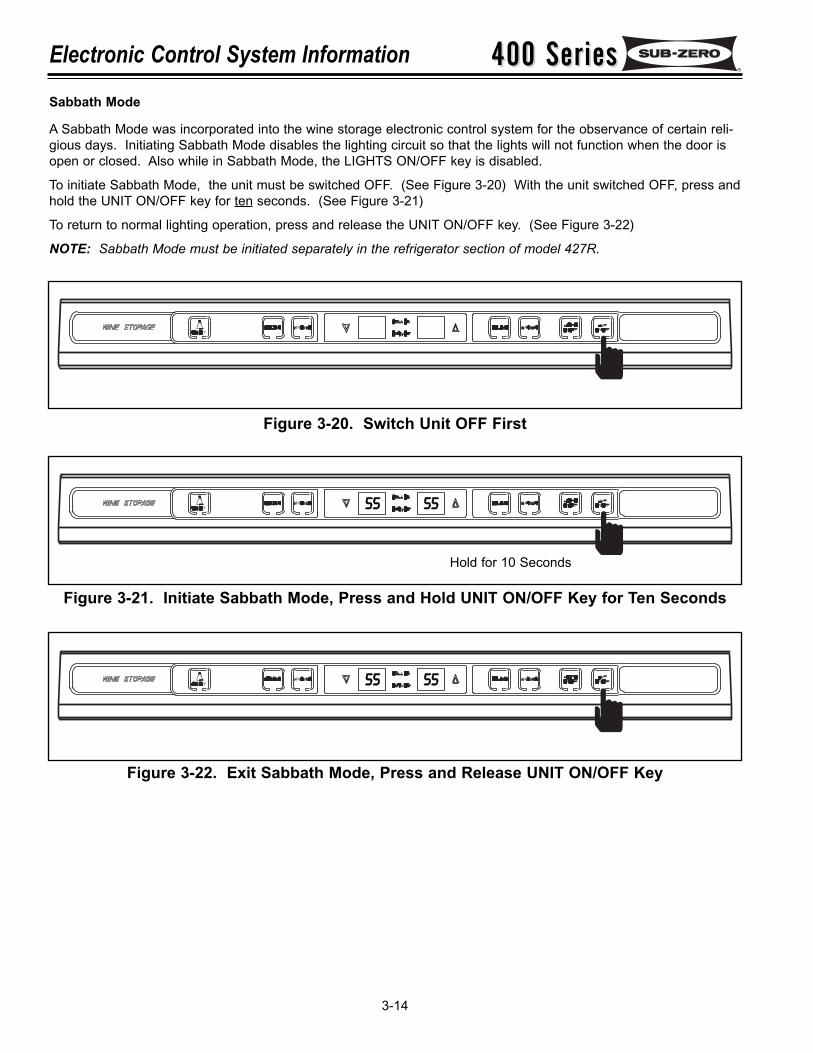
Sabbath Mode
A Sabbath Mode was incorporated into the wine storage electronic control system for the observance of certain reli-gious days. Initiating Sabbath Mode disables the lighting circuit so that the lights will not function when the door isopen or closed. Also while in Sabbath Mode, the LIGHTS ON/OFF key is disabled.
To initiate Sabbath Mode, the unit must be switched OFF. (See Figure 3-20) With the unit switched OFF, press andhold the UNIT ON/OFF key for ten seconds. (See Figure 3-21)
To return to normal lighting operation, press and release the UNIT ON/OFF key. (See Figure 3-22)
NOTE: Sabbath Mode must be initiated separately in the refrigerator section of model 427R.
Figure 3-20. Switch Unit OFF First
Figure 3-21. Initiate Sabbath Mode, Press and Hold UNIT ON/OFF Key for Ten Seconds
5555 5555
Figure 3-22. Exit Sabbath Mode, Press and Release UNIT ON/OFF Key
5555 5555
Hold for 10 Seconds
400 Series400 Series Electronic Control System Information
3-15
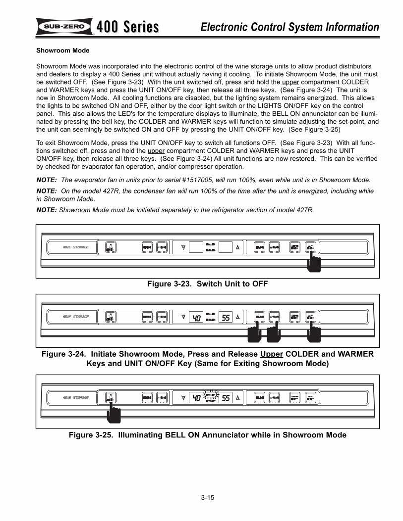
Showroom Mode
Showroom Mode was incorporated into the electronic control of the wine storage units to allow product distributorsand dealers to display a 400 Series unit without actually having it cooling. To initiate Showroom Mode, the unit mustbe switched OFF. (See Figure 3-23) With the unit switched off, press and hold the upper compartment COLDERand WARMER keys and press the UNIT ON/OFF key, then release all three keys. (See Figure 3-24) The unit isnow in Showroom Mode. All cooling functions are disabled, but the lighting system remains energized. This allowsthe lights to be switched ON and OFF, either by the door light switch or the LIGHTS ON/OFF key on the controlpanel. This also allows the LED's for the temperature displays to illuminate, the BELL ON annunciator can be illumi-nated by pressing the bell key, the COLDER and WARMER keys will function to simulate adjusting the set-point, andthe unit can seemingly be switched ON and OFF by pressing the UNIT ON/OFF key. (See Figure 3-25)
To exit Showroom Mode, press the UNIT ON/OFF key to switch all functions OFF. (See Figure 3-23) With all func-tions switched off, press and hold the upper compartment COLDER and WARMER keys and press the UNITON/OFF key, then release all three keys. (See Figure 3-24) All unit functions are now restored. This can be verifiedby checked for evaporator fan operation, and/or compressor operation.
NOTE: The evaporator fan in units prior to serial #1517005, will run 100%, even while unit is in Showroom Mode.NOTE: On the model 427R, the condenser fan will run 100% of the time after the unit is energized, including whilein Showroom Mode.NOTE: Showroom Mode must be initiated separately in the refrigerator section of model 427R.
Figure 3-23. Switch Unit to OFF
Figure 3-24. Initiate Showroom Mode, Press and Release Upper COLDER and WARMERKeys and UNIT ON/OFF Key (Same for Exiting Showroom Mode)
Figure 3-25. Illuminating BELL ON Annunciator while in Showroom Mode
4400 5555
55554400
400 Series400 SeriesElectronic Control System Information
3-16
WINE STORAGE TEMPERATURE ALARM FEATURE AND POSSIBLE ERROR INDICATORS:All wine storage units are equipped with an audio-visual temperature alarm feature. Low voltage wiring provisionson all 400 Series units also makes it possible to tie the temperature alarm feature into a home security alarm sys-tem. This section explains the temperature alarm feature and the audio and/or visual error indicators that may alerta customer of a malfunction.
NOTE: If the temperature alarm feature is tied into a home security system, the connections are made using thesecurity system’s logic. If problems occur between the wine storage unit and the security system, then a homesecurity system technician should be contacted.
NOTE: The refrigerator section of the model 427R uses a separate and unique electronic control system. See427R REFRIGERATOR SECTION, POSSIBLE ERROR INDICATORS.
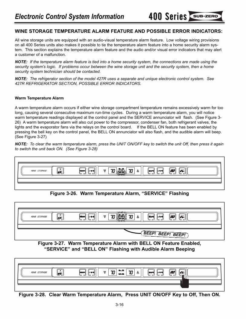
Warm Temperature Alarm
A warm temperature alarm occurs if either wine storage compartment temperature remains excessively warm for toolong, causing several consecutive maximum run-time cycles. During a warm temperature alarm, you will noticewarm temperature readings displayed at the control panel and the SERVICE annunciator will flash. (See Figure 3-26) A warm temperature alarm will also cut power to the compressor, condenser fan, both refrigerant valves, thelights and the evaporator fans via the relays on the control board. If the BELL ON feature has been enabled bypressing the bell key on the control panel, the BELL ON annunciator will also flash, and the audible alarm will beep.(See Figure 3-27)
NOTE: To clear the warm temperature alarm, press the UNIT ON/OFF key to switch the unit Off, then press it againto switch the unit back ON. (See Figure 3-28)
Figure 3-26. Warm Temperature Alarm, “SERVICE” Flashing
7700 7700
7700 7700
Figure 3-27. Warm Temperature Alarm with BELL ON Feature Enabled, “SERVICE” and “BELL ON” Flashing with Audible Alarm Beeping
7700 7700
BEEP! BEEP! BEEP!
Figure 3-28. Clear Warm Temperature Alarm, Press UNIT ON/OFF Key to Off, Then ON.
400 Series400 Series Electronic Control System Information
3-17
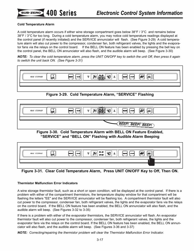
Cold Temperature Alarm
A cold temperature alarm occurs if either wine storage compartment goes below 38°F / 3°C and remains below38°F / 3°C for too long. During a cold temperature alarm, you may notice cold temperature readings displayed atthe control panel (if recently initiated) and the SERVICE annunciator will flash. (See Figure 3-29) A cold tempera-ture alarm will also cut power to the compressor, condenser fan, both refrigerant valves, the lights and the evapora-tor fans via the relays on the control board. If the BELL ON feature has been enabled by pressing the bell key onthe control panel, the BELL ON annunciator will also flash, and the audible alarm will beep. (See Figure 3-30)
NOTE: To clear the cold temperature alarm, press the UNIT ON/OFF key to switch the unit Off, then press it againto switch the unit back ON. (See Figure 3-31)
Figure 3-29. Cold Temperature Alarm, “SERVICE” Flashing
3344 4400
3344 4400
Figure 3-30. Cold Temperature Alarm with BELL ON Feature Enabled, “SERVICE” and “BELL ON” Flashing with Audible Alarm Beeping
3344 4400
BEEP! BEEP! BEEP!
Figure 3-31. Clear Cold Temperature Alarm, Press UNIT ON/OFF Key to Off, Then ON.
Thermistor Malfunction Error Indicators
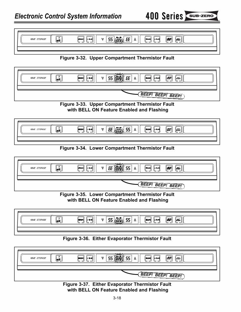
A wine storage thermistor fault, such as a short or open condition, will be displayed at the control panel. If there is aproblem with either of the compartment thermistors, the temperature display window for that compartment will beflashing the letters "EE" and the SERVICE annunciator will be flashing too. A compartment thermistor fault will alsocut power to the compressor, condenser fan, both refrigerant valves, the lights and the evaporator fans via the relayson the control board. If the BELL ON feature has been enabled, the BELL ON annunciator will also flash, and theaudible alarm will beep. (See Figures 3-32 to 3-35)
If there is a problem with either of the evaporator thermistors, the SERVICE annunciator will flash. An evaporatorthermistor fault will also cut power to the compressor, condenser fan, both refrigerant valves, the lights and theevaporator fans via the relays on the control board. If the BELL ON feature has been enabled, the BELL ON annun-ciator will also flash, and the audible alarm will beep. (See Figures 3-36 and 3-37)
NOTE: Correcting/repairing the thermistor problem will clear the Thermistor Malfunction Error Indicator.
400 Series400 SeriesElectronic Control System Information
3-18
Figure 3-32. Upper Compartment Thermistor Fault
5555 EEEE
Figure 3-33. Upper Compartment Thermistor Faultwith BELL ON Feature Enabled and Flashing
5555 EEEE
BEEP! BEEP! BEEP!
Figure 3-34. Lower Compartment Thermistor Fault
eeee 5555
Figure 3-35. Lower Compartment Thermistor Faultwith BELL ON Feature Enabled and Flashing
EEEE 5555
BEEP! BEEP! BEEP!
Figure 3-36. Either Evaporator Thermistor Fault
5555 5555
Figure 3-37. Either Evaporator Thermistor Faultwith BELL ON Feature Enabled and Flashing
5555 5555
BEEP! BEEP! BEEP!
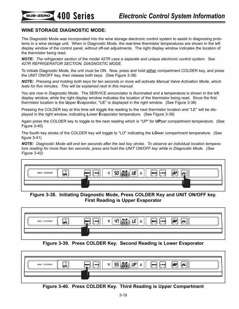
400 Series400 Series Electronic Control System Information
3-19
WINE STORAGE DIAGNOSTIC MODE:The Diagnostic Mode was incorporated into the wine storage electronic control system to assist in diagnosing prob-lems in a wine storage unit. When in Diagnostic Mode, the real-time thermistor temperatures are shown in the leftdisplay window of the control panel, without off-set adjustments. The right display window indicates the location ofthe thermistor being read.NOTE: The refrigerator section of the model 427R uses a separate and unique electronic control system. See427R REFRIGERATOR SECTION, DIAGNOSTIC MODE.
To initiate Diagnostic Mode, the unit must be ON. Now, press and hold either compartment COLDER key, and pressthe UNIT ON/OFF key, then release both keys. (See Figure 3-38)NOTE: Pressing and holding both keys for ten seconds or more will activate Manual Valve Activation Mode, whichlasts for five minutes. This will be explained next in this manual.
You are now in Diagnostic Mode. The SERVICE annunciator is illuminated and a temperature is shown in the leftdisplay window, while the right display window indicates the location of the thermistor being read. Since the firstthermistor location is the Upper Evaporator, "UE" is displayed in the right window. (See Figure 3-38)
Pressing the COLDER key at this time will toggle the reading to the next thermistor location and "LE" will be dis-played in the right window, indicating Lower Evaporator temperature. (See Figure 3-39)
Again press the COLDER key to toggle to the next reading which is "UP" for UPper compartment temperature. (SeeFigure 3-40)
The fourth key stroke of the COLDER key will toggle to "LO" indicating the LOwer compartment temperature. (Seefigure 3-41)NOTE: Diagnostic Mode will end ten seconds after the last key stroke. To observe an individual location tempera-ture reading for more than ten seconds, press and hold the UNIT ON/OFF key while in Diagnostic Mode. (SeeFigure 3-42)
5500 UUEE
Figure 3-38. Initiating Diagnostic Mode, Press COLDER Key and UNIT ON/OFF key.First Reading is Upper Evaporator
4477 LLEE
Figure 3-39. Press COLDER Key. Second Reading is Lower Evaporator
5555 UUPP
Figure 3-40. Press COLDER Key. Third Reading is Upper Compartment
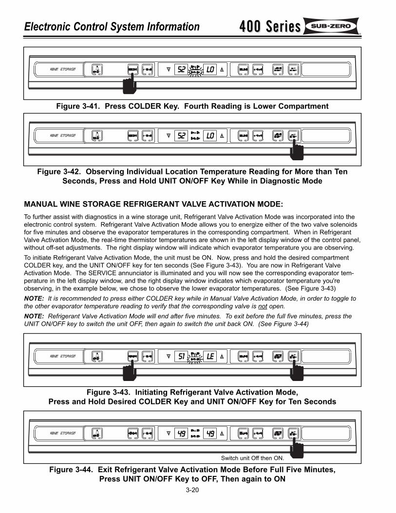
400 Series400 SeriesElectronic Control System Information
3-20
5522 LLOO
Figure 3-41. Press COLDER Key. Fourth Reading is Lower Compartment
MANUAL WINE STORAGE REFRIGERANT VALVE ACTIVATION MODE:To further assist with diagnostics in a wine storage unit, Refrigerant Valve Activation Mode was incorporated into theelectronic control system. Refrigerant Valve Activation Mode allows you to energize either of the two valve solenoidsfor five minutes and observe the evaporator temperatures in the corresponding compartment. When in RefrigerantValve Activation Mode, the real-time thermistor temperatures are shown in the left display window of the control panel,without off-set adjustments. The right display window will indicate which evaporator temperature you are observing.To initiate Refrigerant Valve Activation Mode, the unit must be ON. Now, press and hold the desired compartmentCOLDER key, and the UNIT ON/OFF key for ten seconds (See Figure 3-43). You are now in Refrigerant ValveActivation Mode. The SERVICE annunciator is illuminated and you will now see the corresponding evaporator tem-perature in the left display window, and the right display window indicates which evaporator temperature you'reobserving, in the example below, we chose to observe the lower evaporator temperatures. (See Figure 3-43)NOTE: It is recommended to press either COLDER key while in Manual Valve Activation Mode, in order to toggle tothe other evaporator temperature reading to verify that the corresponding valve is not open.NOTE: Refrigerant Valve Activation Mode will end after five minutes. To exit before the full five minutes, press theUNIT ON/OFF key to switch the unit OFF, then again to switch the unit back ON. (See Figure 3-44)
5522 LLOO
Figure 3-42. Observing Individual Location Temperature Reading for More than TenSeconds, Press and Hold UNIT ON/OFF Key While in Diagnostic Mode
5511 LLEE
Figure 3-43. Initiating Refrigerant Valve Activation Mode,Press and Hold Desired COLDER Key and UNIT ON/OFF Key for Ten Seconds
4499 4499
Figure 3-44. Exit Refrigerant Valve Activation Mode Before Full Five Minutes, Press UNIT ON/OFF Key to OFF, Then again to ON
Switch unit Off then ON.
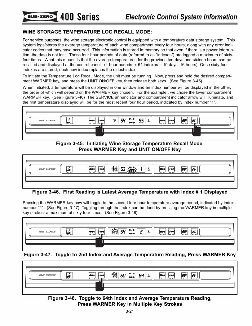
400 Series400 Series Electronic Control System Information
3-21
WINE STORAGE TEMPERATURE LOG RECALL MODE:For service purposes, the wine storage electronic control is equipped with a temperature data storage system. Thissystem logs/stores the average temperature of each wine compartment every four hours, along with any error indi-cator codes that may have occurred. This information is stored in memory so that even if there is a power interrup-tion, the data is not lost. These four hour periods of data (referred to as "indexes") are logged a maximum of sixty-four times. What this means is that the average temperatures for the previous ten days and sixteen hours can berecalled and displayed at the control panel. (4 hour periods x 64 indexes = 10 days, 16 hours) Once sixty-fourindexes are stored, each new index replaces the oldest index.To initiate the Temperature Log Recall Mode, the unit must be running. Now, press and hold the desired compart-ment WARMER key, and press the UNIT ON/OFF key, then release both keys. (See Figure 3-45)When initiated, a temperature will be displayed in one window and an index number will be displayed in the other,the order of which will depend on the WARMER key chosen. For the example , we chose the lower compartmentWARMER key. (See Figure 3-46) The SERVICE annunciator and compartment indicator arrow will illuminate, andthe first temperature displayed will be for the most recent four hour period, indicated by index number "1".
5544 5555
Figure 3-45. Initiating Wine Storage Temperature Recall Mode, Press WARMER Key and UNIT ON/OFF Key
5533 11
Figure 3-46. First Reading is Latest Average Temperature with Index # 1 Displayed
Pressing the WARMER key now will toggle to the second four hour temperature average period, indicated by indexnumber "2". (See Figure 3-47) Toggling through the index can be done by pressing the WARMER key in multiplekey strokes, a maximum of sixty-four times. (See Figure 3-48)
5544 22
Figure 3-47. Toggle to 2nd Index and Average Temperature Reading, Press WARMER Key
6600 6644
Figure 3-48. Toggle to 64th Index and Average Temperature Reading, Press WARMER Key in Multiple Key Strokes
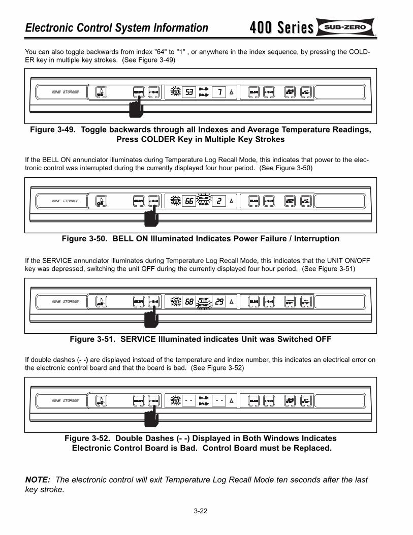
400 Series400 SeriesElectronic Control System Information
3-22
You can also toggle backwards from index "64" to "1" , or anywhere in the index sequence, by pressing the COLD-ER key in multiple key strokes. (See Figure 3-49)
5533 77
Figure 3-49. Toggle backwards through all Indexes and Average Temperature Readings,Press COLDER Key in Multiple Key Strokes
If the BELL ON annunciator illuminates during Temperature Log Recall Mode, this indicates that power to the elec-tronic control was interrupted during the currently displayed four hour period. (See Figure 3-50)
6666 22
Figure 3-50. BELL ON Illuminated Indicates Power Failure / Interruption
If the SERVICE annunciator illuminates during Temperature Log Recall Mode, this indicates that the UNIT ON/OFFkey was depressed, switching the unit OFF during the currently displayed four hour period. (See Figure 3-51)
6688 2299
Figure 3-51. SERVICE Illuminated indicates Unit was Switched OFF
If double dashes (- -) are displayed instead of the temperature and index number, this indicates an electrical error onthe electronic control board and that the board is bad. (See Figure 3-52)
- - - -
Figure 3-52. Double Dashes (- -) Displayed in Both Windows IndicatesElectronic Control Board is Bad. Control Board must be Replaced.
NOTE: The electronic control will exit Temperature Log Recall Mode ten seconds after the lastkey stroke.
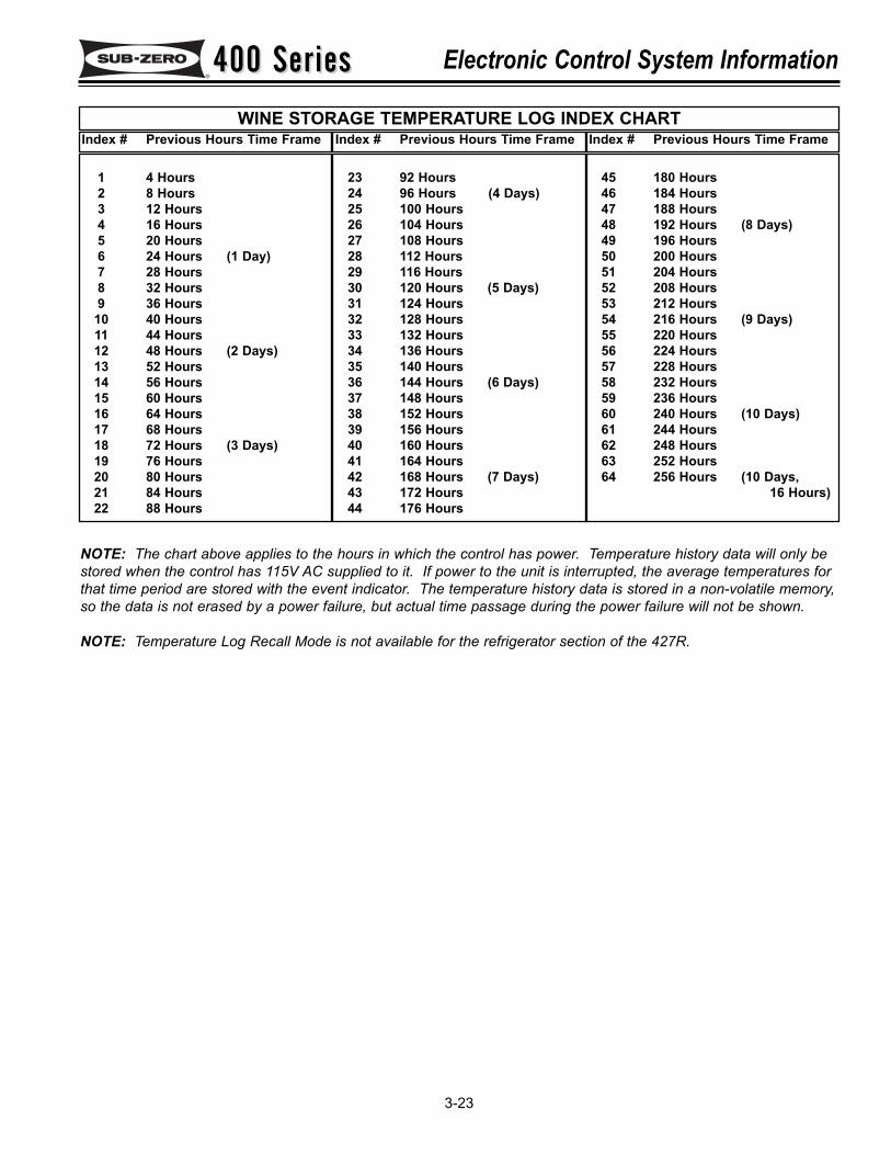
400 Series400 Series Electronic Control System Information
3-23
1 4 Hours2 8 Hours3 12 Hours4 16 Hours5 20 Hours6 24 Hours (1 Day)7 28 Hours8 32 Hours9 36 Hours
10 40 Hours11 44 Hours12 48 Hours (2 Days)13 52 Hours14 56 Hours15 60 Hours16 64 Hours17 68 Hours18 72 Hours (3 Days)19 76 Hours20 80 Hours21 84 Hours22 88 Hours
23 92 Hours24 96 Hours (4 Days)25 100 Hours26 104 Hours27 108 Hours28 112 Hours29 116 Hours30 120 Hours (5 Days)31 124 Hours32 128 Hours33 132 Hours34 136 Hours35 140 Hours36 144 Hours (6 Days)37 148 Hours38 152 Hours39 156 Hours40 160 Hours41 164 Hours42 168 Hours (7 Days)43 172 Hours44 176 Hours
WINE STORAGE TEMPERATURE LOG INDEX CHART
45 180 Hours46 184 Hours47 188 Hours48 192 Hours (8 Days)49 196 Hours50 200 Hours51 204 Hours52 208 Hours53 212 Hours54 216 Hours (9 Days)55 220 Hours56 224 Hours57 228 Hours58 232 Hours59 236 Hours60 240 Hours (10 Days)61 244 Hours62 248 Hours63 252 Hours64 256 Hours (10 Days,
16 Hours)
Index # Previous Hours Time Frame Index # Previous Hours Time Frame Index # Previous Hours Time Frame
NOTE: The chart above applies to the hours in which the control has power. Temperature history data will only bestored when the control has 115V AC supplied to it. If power to the unit is interrupted, the average temperatures forthat time period are stored with the event indicator. The temperature history data is stored in a non-volatile memory,so the data is not erased by a power failure, but actual time passage during the power failure will not be shown.
NOTE: Temperature Log Recall Mode is not available for the refrigerator section of the 427R.
400 Series400 SeriesElectronic Control System Information
3-24
MODEL 427R REFRIGERATOR ELECTRONIC CONTROL TERMINOLOGY & COMPONENTDESCRIPTIONS:
The refrigerator section and the wine storage section of the model 427R use separate and unique electronic controlsystems. Like the wine storage control, the refrigerator electronic control monitors, regulates and controls a varietyof functions, to include display of temperatures and possible problems with the unit. But, there is not a temperaturealarm associated with the refrigerator electronic control. Instead, a "drawer ajar alarm" is provided. Another differ-ence lies in the display area where an LCD (Liquid Crystal Display) is used, instead of LCD’s.
The table below defines some basic 427R refrigerator electronic control system terminology and describes some ofthe electronic control components. An understanding of the following information is needed in order to comprehendthis control system.
Term/Component Definition / Description
Control Board …………………………..The printed-circuit board (PC Board) contains the microprocessor, relays andelectrical connections which control and monitor all functions and operationsof the unit.
Microprocessor ………………………...An electrical component on the control board which receives electrical signalsfrom other components, processes that information, then sends an electricalsignal to the relays on the board to open or close, and other electronic com-ponents in the unit to switch on or off.
Relay …………………………………… The electrical components on the control board which close or open to eitherallow power to the appropriate component(s), or interrupts power from reach-ing appropriate component(s).
LCD (Liquid Crystal Display) ………… For our purposes, this is the part of the control panel which electronically dis-plays temperature values and possible error signals.
Control Panel Assembly ………………The information input and read-out area of the electronic control system,located inside the top drawer assembly, at top front.
Membrane Switch …………………….. An integral part of the control panel assembly, which consists of the functionkeys used for all input functions to the electronic control system.
Keys (Function Keys) ………………… The buttons on the Membrane switch used for input functions. The keys are:UNIT ON/OFF, ALARM (drawer ajar alarm ON/OFF) COLDER, WARMER.
Annunciators …………………………...The words and numbers that are displayed at the control panel assembly.(Example: Temperature readings, drawer indicator, drawer ajar bell)
Set-Point ………………………………..The desired compartment temperature. This is the approximate average ofthe high offset and the low offset.
High Offset (Cut-in)………………….....During normal operation, this is the maximum compartment air temperaturethat the electronic control system will allow before calling for cooling.
Low Offset (Cut-out)…………………... During normal operation, this is the minimum compartment air temperaturethat the electronic control system will allow before interrupting cooling.
Offset Temperature Range …………... The difference between the low offset and the high offset.
Thermistor (Temperature Sensor) ….. A resistor with which resistance changes as the temperature around itchanges. For electronic control system purposes, the microprocessor deci-phers this resistance as temperature.
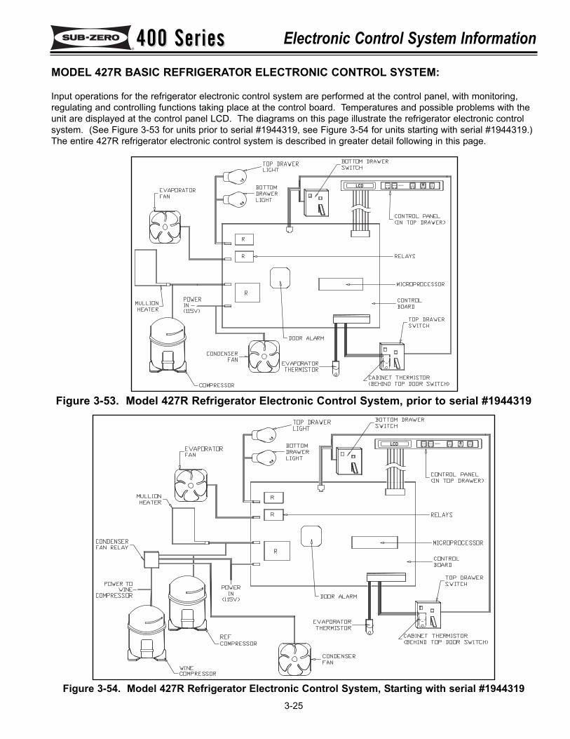
400 Series400 Series Electronic Control System Information
3-25
Figure 3-53. Model 427R Refrigerator Electronic Control System, prior to serial #1944319
MODEL 427R BASIC REFRIGERATOR ELECTRONIC CONTROL SYSTEM:
Input operations for the refrigerator electronic control system are performed at the control panel, with monitoring,regulating and controlling functions taking place at the control board. Temperatures and possible problems with theunit are displayed at the control panel LCD. The diagrams on this page illustrate the refrigerator electronic controlsystem. (See Figure 3-53 for units prior to serial #1944319, see Figure 3-54 for units starting with serial #1944319.)The entire 427R refrigerator electronic control system is described in greater detail following in this page.
FREEZERON/OFF
ICE
ON/OFF
UNITCOLDER WARMER
ON/OFFLCD
Figure 3-54. Model 427R Refrigerator Electronic Control System, Starting with serial #1944319
FREEZERON/OFF
ICE
ON/OFF
UNITCOLDER WARMER
ON/OFFLCD
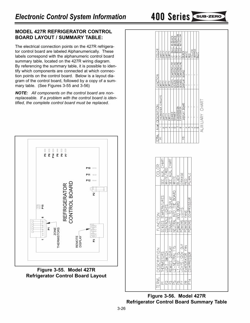
400 Series400 SeriesElectronic Control System Information
3-26
MODEL 427R REFRIGERATOR CONTROLBOARD LAYOUT / SUMMARY TABLE:The electrical connection points on the 427R refrigera-tor control board are labeled Alphanumerically. Theselabels correspond with the alphanumeric control boardsummary table, located on the 427R wiring diagram.By referencing the summary table, it is possible to iden-tify which components are connected at which connec-tion points on the control board. Below is a layout dia-gram of the control board, followed by a copy of a sum-mary table. (See Figures 3-55 and 3-56)
NOTE: All components on the control board are non-replaceable. If a problem with the control board is iden-tified, the complete control board must be replaced.
Figure 3-55. Model 427RRefrigerator Control Board Layout
Figure 3-56. Model 427RRefrigerator Control Board Summary Table
REF
RIG
ERAT
OR
CO
NTR
OL
BOAR
DR
EMO
TED
ISPL
AY
ZON
ETH
ERM
ISTO
RSP1
P3P2
P15
18
P12
P11
P10
P5 P6 P14 P8 P9 P7
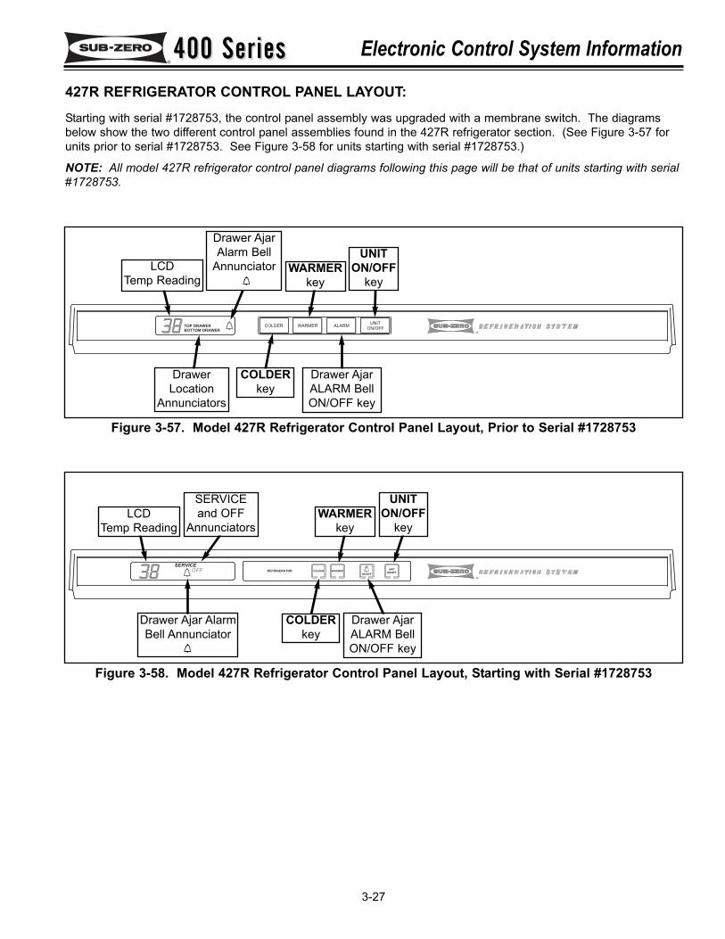
400 Series400 Series Electronic Control System Information
3-27
TOP DRAWER
BOTTOM DRAWERTM
COLDER WARMER ALARMUNIT
ON/OFF
Figure 3-57. Model 427R Refrigerator Control Panel Layout, Prior to Serial #1728753
Drawer AjarAlarm Bell
Annunciator
427R REFRIGERATOR CONTROL PANEL LAYOUT:Starting with serial #1728753, the control panel assembly was upgraded with a membrane switch. The diagramsbelow show the two different control panel assemblies found in the 427R refrigerator section. (See Figure 3-57 forunits prior to serial #1728753. See Figure 3-58 for units starting with serial #1728753.)
NOTE: All model 427R refrigerator control panel diagrams following this page will be that of units starting with serial#1728753.
COLDERkey
Drawer AjarALARM BellON/OFF key
DrawerLocation
Annunciators
LCDTemp Reading
UNITON/OFF
keyWARMER
key
SERVICE
OFF
TM
COLDER WARMER
ON/OFF
REFRIGERATORUNIT
ON/OFF
Figure 3-58. Model 427R Refrigerator Control Panel Layout, Starting with Serial #1728753
Drawer Ajar Alarm Bell Annunciator
COLDERkey
Drawer AjarALARM BellON/OFF key
LCDTemp Reading
UNITON/OFF
keyWARMER
key
SERVICEand OFF
Annunciators
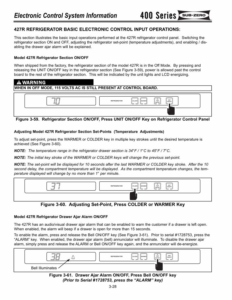
400 Series400 SeriesElectronic Control System Information
3-28
COLDER WARMER
ON/OFF
REFRIGERATORUNIT
ON/OFF
Adjusting Model 427R Refrigerator Section Set-Points (Temperature Adjustments)
To adjust set-point, press the WARMER or COLDER key in multiple key strokes until the desired temperature isachieved (See Figure 3-60).
NOTE: The temperature range in the refrigerator drawer section is 34°F / 1°C to 45°F / 7°C.
NOTE: The initial key stroke of the WARMER or COLDER keys will change the previous set-point.
NOTE: The set-point will be displayed for 10 seconds after the last WARMER or COLDER key stroke. After the 10second delay, the compartment temperature will be displayed. As the compartment temperature changes, the tem-perature displayed will change by no more than 1° per minute.
Figure 3-60. Adjusting Set-Point, Press COLDER or WARMER Key
Model 427R Refrigerator Drawer Ajar Alarm ON/OFF
The 427R has an audio/visual drawer ajar alarm that can be enabled to warn the customer if a drawer is left open.When enabled, the alarm will beep if a drawer is open for more than 15 seconds.To enable the alarm, press and release the Bell ON/OFF key (See Figure 3-61). Prior to serial #1728753, press the“ALARM” key. When enabled, the drawer ajar alarm (bell) annunciator will illuminate. To disable the drawer ajaralarm, simply press and release the ALARM or Bell ON/OFF key again, and the annunciator will de-energize.
COLDER WARMER
ON/OFF
REFRIGERATORUNIT
ON/OFF
Figure 3-61. Drawer Ajar Alarm ON/OFF, Press Bell ON/OFF key(Prior to Serial #1728753, press the “ALARM” key)
Bell Illuminates
427R REFRIGERATOR BASIC ELECTRONIC CONTROL INPUT OPERATIONS:This section illustrates the basic input operations performed at the 427R refrigerator control panel. Switching therefrigerator section ON and OFF, adjusting the refrigerator set-point (temperature adjustments), and enabling / dis-abling the drawer ajar alarm will be explained.
Model 427R Refrigerator Section ON/OFF
When shipped from the factory, the refrigerator section of the model 427R is in the Off Mode. By pressing andreleasing the UNIT ON/OFF key in the refrigerator section (See Figure 3-59), power is allowed past the controlboard to the rest of the refrigerator section. This will be indicated by the unit lights and LCD energizing.
WHEN IN OFF MODE, 115 VOLTS AC IS STILL PRESENT AT CONTROL BOARD.
COLDER WARMER
ON/OFF
REFRIGERATORUNIT
ON/OFF
Figure 3-59. Refrigerator Section ON/OFF, Press UNIT ON/OFF Key on Refrigerator Control Panel
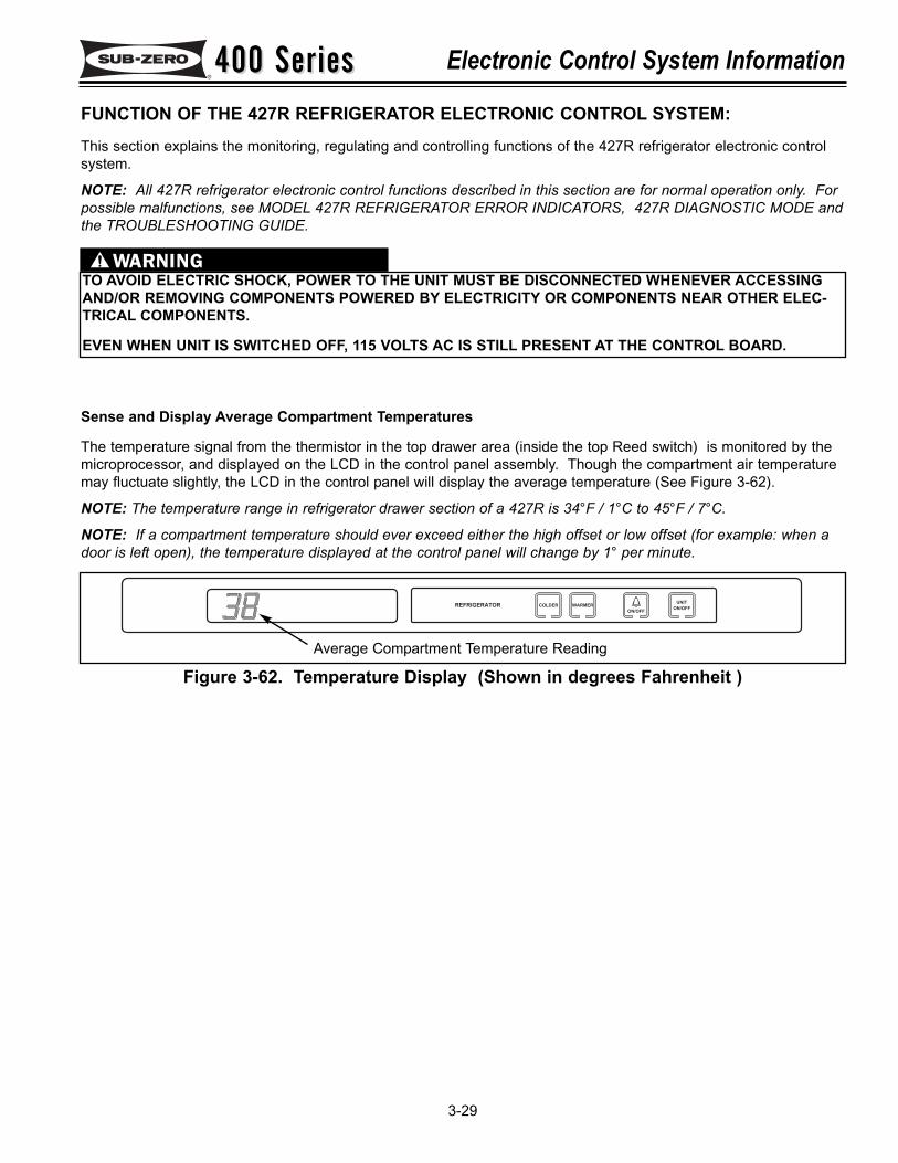
400 Series400 Series Electronic Control System Information
3-29
FUNCTION OF THE 427R REFRIGERATOR ELECTRONIC CONTROL SYSTEM:This section explains the monitoring, regulating and controlling functions of the 427R refrigerator electronic controlsystem.
NOTE: All 427R refrigerator electronic control functions described in this section are for normal operation only. Forpossible malfunctions, see MODEL 427R REFRIGERATOR ERROR INDICATORS, 427R DIAGNOSTIC MODE andthe TROUBLESHOOTING GUIDE.
TO AVOID ELECTRIC SHOCK, POWER TO THE UNIT MUST BE DISCONNECTED WHENEVER ACCESSINGAND/OR REMOVING COMPONENTS POWERED BY ELECTRICITY OR COMPONENTS NEAR OTHER ELEC-TRICAL COMPONENTS.
EVEN WHEN UNIT IS SWITCHED OFF, 115 VOLTS AC IS STILL PRESENT AT THE CONTROL BOARD.
Sense and Display Average Compartment Temperatures
The temperature signal from the thermistor in the top drawer area (inside the top Reed switch) is monitored by themicroprocessor, and displayed on the LCD in the control panel assembly. Though the compartment air temperaturemay fluctuate slightly, the LCD in the control panel will display the average temperature (See Figure 3-62).
NOTE: The temperature range in refrigerator drawer section of a 427R is 34°F / 1°C to 45°F / 7°C.
NOTE: If a compartment temperature should ever exceed either the high offset or low offset (for example: when adoor is left open), the temperature displayed at the control panel will change by 1° per minute.
COLDER WARMER
ON/OFF
REFRIGERATORUNIT
ON/OFF
Figure 3-62. Temperature Display (Shown in degrees Fahrenheit )Average Compartment Temperature Reading
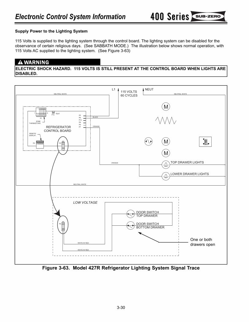
400 Series400 SeriesElectronic Control System Information
3-30
115 VOLTS
60 CYCLES
NEUTRAL WHITE
NEUTRAL WHITE
REFRIGERATOR
CONTROL BOARD
P3 P2
1
P1
TESTP15
8
P5
P9
P7
P8
P14
P6
ORANGE
BLACK
ORANGE
L1
LOWER DRAWER LIGHTS
TOP DRAWER LIGHTS
M
M
NEUTRAL WHITE
NEUT
M
REMOTE
DISPLAY
ZONE
THERMISTORS
LOW VOLTAGE
BOTTOM DRAWER
WHITE W/ RED
WHITE W/ RED
P2 DOOR SWITCH
TOP DRAWER
DOOR SWITCH
Supply Power to the Lighting System
115 Volts is supplied to the lighting system through the control board. The lighting system can be disabled for theobservance of certain religious days. (See SABBATH MODE.) The illustration below shows normal operation, with115 Volts AC supplied to the lighting system. (See Figure 3-63)
ELECTRIC SHOCK HAZARD. 115 VOLTS IS STILL PRESENT AT THE CONTROL BOARD WHEN LIGHTS AREDISABLED.
Figure 3-63. Model 427R Refrigerator Lighting System Signal Trace
One or bothdrawers open
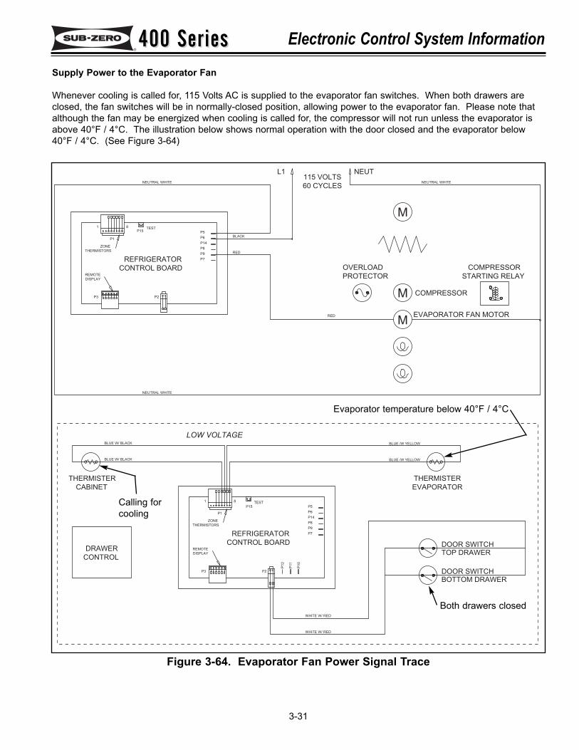
400 Series400 Series Electronic Control System Information
3-31
Supply Power to the Evaporator Fan
Whenever cooling is called for, 115 Volts AC is supplied to the evaporator fan switches. When both drawers areclosed, the fan switches will be in normally-closed position, allowing power to the evaporator fan. Please note thatalthough the fan may be energized when cooling is called for, the compressor will not run unless the evaporator isabove 40°F / 4°C. The illustration below shows normal operation with the door closed and the evaporator below40°F / 4°C. (See Figure 3-64)
115 VOLTS
60 CYCLES
L1
STARTING RELAY
COMPRESSOR
COMPRESSOR
PROTECTOR
OVERLOAD
NEUT
BOTTOM DRAWER
WHITE W/ RED
WHITE W/ RED
NEUTRAL WHITE
THERMISTER
CONTROL
DRAWER
BLUE W/ BLACK
CABINET
BLUE W/ BLACK
CONTROL BOARD
REFRIGERATOR
ZONE
THERMISTORS
P1
REMOTE
DISPLAY
P3
1 8
P6
P2
P12
P8
P14
P10
P11
P9
P7
TEST
P15 P5
NEUTRAL WHITE
REFRIGERATOR
CONTROL BOARDREMOTE
DISPLAY
P3 P2
ZONE
THERMISTORS
1
P1
TESTP15
8
P5
P9
P7
P8
P14
P6
RED
BLACK
RED
BLUE /W YELLOW
DOOR SWITCH
TOP DRAWER
DOOR SWITCH
THERMISTER
EVAPORATOR
BLUE /W YELLOW
EVAPORATOR FAN MOTOR
M
M
NEUTRAL WHITE
M
LOW VOLTAGE
Figure 3-64. Evaporator Fan Power Signal Trace
Evaporator temperature below 40°F / 4°C
Calling forcooling
Both drawers closed
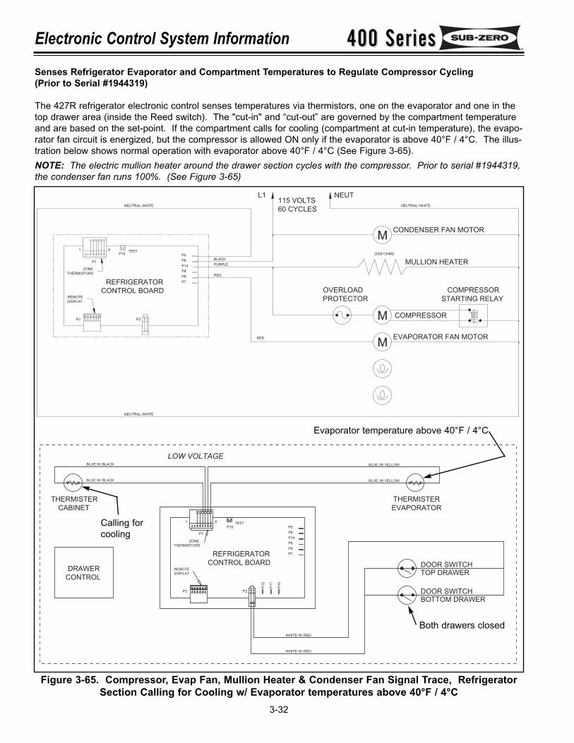
400 Series400 SeriesElectronic Control System Information
3-32
Senses Refrigerator Evaporator and Compartment Temperatures to Regulate Compressor Cycling(Prior to Serial #1944319)
The 427R refrigerator electronic control senses temperatures via thermistors, one on the evaporator and one in thetop drawer area (inside the Reed switch). The "cut-in" and “cut-out” are governed by the compartment temperatureand are based on the set-point. If the compartment calls for cooling (compartment at cut-in temperature), the evapo-rator fan circuit is energized, but the compressor is allowed ON only if the evaporator is above 40°F / 4°C. The illus-tration below shows normal operation with evaporator above 40°F / 4°C (See Figure 3-65).NOTE: The electric mullion heater around the drawer section cycles with the compressor. Prior to serial #1944319,the condenser fan runs 100%. (See Figure 3-65)
Figure 3-65. Compressor, Evap Fan, Mullion Heater & Condenser Fan Signal Trace, RefrigeratorSection Calling for Cooling w/ Evaporator temperatures above 40°F / 4°C
BOTTOM DRAWER
WHITE W/ RED
WHITE W/ RED
THERMISTER
CONTROL
DRAWER
BLUE W/ BLACK
CABINET
BLUE W/ BLACK
CONTROL BOARD
REFRIGERATOR
ZONE
THERMISTORS
P1
REMOTE
DISPLAY
P3
1 8
P6
P2
P12
P8
P14
P10
P11
P9
P7
TEST
P15 P5
BLUE /W YELLOW
DOOR SWITCH
TOP DRAWER
DOOR SWITCH
THERMISTER
EVAPORATOR
BLUE /W YELLOW
LOW VOLTAGE
115 VOLTS
60 CYCLES
NEUTRAL WHITE
NEUTRAL WHITE
REFRIGERATOR
CONTROL BOARD
P3 P2
1
P1
TESTP15
8
P5
P9
P7
P8
P14
P6
RED
PURPLE
BLACK
RED
L1
CONDENSER FAN MOTOR
STARTING RELAY
COMPRESSOR
EVAPORATOR FAN MOTOR
COMPRESSORM
M
PROTECTOR
OVERLOAD
2000 OHMS
MULLION HEATER
NEUTRAL WHITE
NEUT
M
REMOTE
DISPLAY
ZONE
THERMISTORS
Evaporator temperature above 40°F / 4°C
Calling forcooling
Both drawers closed
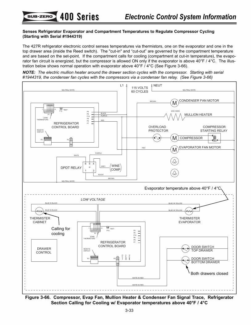
400 Series400 Series Electronic Control System Information
3-33
Senses Refrigerator Evaporator and Compartment Temperatures to Regulate Compressor Cycling(Starting with Serial #1944319)
The 427R refrigerator electronic control senses temperatures via thermistors, one on the evaporator and one in thetop drawer area (inside the Reed switch). The "cut-in" and “cut-out” are governed by the compartment temperatureand are based on the set-point. If the compartment calls for cooling (compartment at cut-in temperature), the evapo-rator fan circuit is energized, but the compressor is allowed ON only if the evaporator is above 40°F / 4°C. The illus-tration below shows normal operation with evaporator above 40°F / 4°C (See Figure 3-66).NOTE: The electric mullion heater around the drawer section cycles with the compressor. Starting with serial#1944319, the condenser fan cycles with the compressors via a condenser fan relay. (See Figure 3-66)
Figure 3-66. Compressor, Evap Fan, Mullion Heater & Condenser Fan Signal Trace, RefrigeratorSection Calling for Cooling w/ Evaporator temperatures above 40°F / 4°C
115 VOLTS
60 CYCLES
L1
STARTING RELAY
COMPRESSOR
COMPRESSOR
PROTECTOR
OVERLOAD
NEUT
31
56 4
DPDT RELAY
NEUTRAL WHITE
NEUTRAL WHITE
REFRIGERATOR
CONTROL BOARDREMOTE
DISPLAY
P3 P2
ZONE
THERMISTORS
1
P1
TESTP15
8
P5
P9
P7
P8
P14
P6
RED
PURPLE
BLACK
RED
CONDENSER FAN MOTOR
EVAPORATOR FAN MOTOR
M
M
2000 OHMS
MULLION HEATER
NEUTRAL WHITE
M
PURPLE
BLACK
WHITE
BROWN
BROWN
BOTTOM DRAWER
WHITE W/ RED
WHITE W/ RED
THERMISTER
CONTROL
DRAWER
BLUE W/ BLACK
CABINET
BLUE W/ BLACK
CONTROL BOARD
REFRIGERATOR
ZONE
THERMISTORS
P1
REMOTE
DISPLAY
P3
1 8
P6
P2
P1
2
P8
P14
P1
0
P1
1
P9
P7
TEST
P15 P5
BLUE /W YELLOW
DOOR SWITCH
TOP DRAWER
DOOR SWITCH
THERMISTER
EVAPORATOR
BLUE /W YELLOW
LOW VOLTAGE
GREY WINE
COMP
Evaporator temperature above 40°F / 4°C
Calling forcooling
Both drawers closed
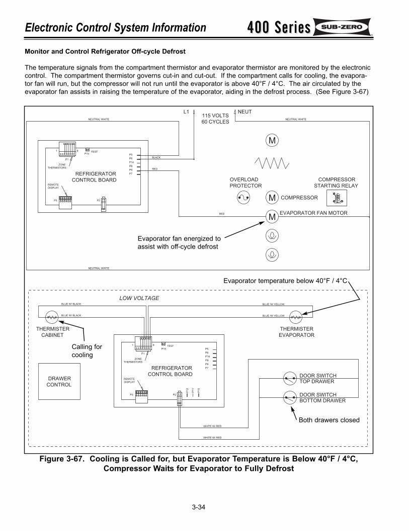
400 Series400 SeriesElectronic Control System Information
3-34
Figure 3-67. Cooling is Called for, but Evaporator Temperature is Below 40°F / 4°C,Compressor Waits for Evaporator to Fully Defrost
Monitor and Control Refrigerator Off-cycle Defrost
The temperature signals from the compartment thermistor and evaporator thermistor are monitored by the electroniccontrol. The compartment thermistor governs cut-in and cut-out. If the compartment calls for cooling, the evapora-tor fan will run, but the compressor will not run until the evaporator is above 40°F / 4°C. The air circulated by theevaporator fan assists in raising the temperature of the evaporator, aiding in the defrost process. (See Figure 3-67)
115 VOLTS
60 CYCLES
L1
STARTING RELAY
COMPRESSOR
COMPRESSOR
PROTECTOR
OVERLOAD
NEUT
BOTTOM DRAWER
WHITE W/ RED
WHITE W/ RED
NEUTRAL WHITE
THERMISTER
CONTROL
DRAWER
BLUE W/ BLACK
CABINET
BLUE W/ BLACK
CONTROL BOARD
REFRIGERATOR
ZONE
THERMISTORS
P1
REMOTE
DISPLAY
P3
1 8
P6
P2
P12
P8
P14
P10
P11
P9
P7
TEST
P15 P5
NEUTRAL WHITE
REFRIGERATOR
CONTROL BOARDREMOTE
DISPLAY
P3 P2
ZONE
THERMISTORS
1
P1
TESTP15
8
P5
P9
P7
P8
P14
P6
RED
BLACK
RED
BLUE /W YELLOW
DOOR SWITCH
TOP DRAWER
DOOR SWITCH
THERMISTER
EVAPORATOR
BLUE /W YELLOW
EVAPORATOR FAN MOTOR
M
M
NEUTRAL WHITE
M
LOW VOLTAGE
Evaporator temperature below 40°F / 4°C
Calling forcooling
Both drawers closed
Evaporator fan energized toassist with off-cycle defrost
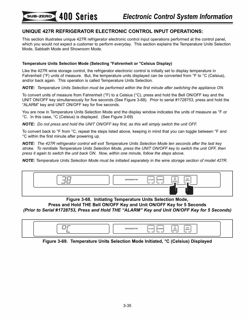
400 Series400 Series Electronic Control System Information
3-35
UNIQUE 427R REFRIGERATOR ELECTRONIC CONTROL INPUT OPERATIONS:This section illustrates unique 427R refrigerator electronic control input operations performed at the control panel,which you would not expect a customer to perform everyday. This section explains the Temperature Units SelectionMode, Sabbath Mode and Showroom Mode.
Temperature Units Selection Mode (Selecting °Fahrenheit or °Celsius Display)
Like the 427R wine storage control, the refrigerator electronic control is initially set to display temperature inFahrenheit (°F) units of measure. But, the temperature units displayed can be converted from °F to °C (Celsius),and/or back again. This operation is called Temperature Units Selection.
NOTE: Temperature Units Selection must be performed within the first minute after switching the appliance ON.
To convert units of measure from Fahrenheit (°F) to a Celsius (°C), press and hold the Bell ON/OFF key and theUNIT ON/OFF key simultaneously for five seconds (See Figure 3-68). Prior to serial #1728753, press and hold the“ALARM” key and UNIT ON/OFF key for five seconds.
You are now in Temperature Units Selection Mode and the display window indicates the units of measure as °F or°C. In this case, °C (Celsius) is displayed. (See Figure 3-69)
NOTE: Do not press and hold the UNIT ON/OFF key first, as this will simply switch the unit OFF.
To convert back to °F from °C, repeat the steps listed above, keeping in mind that you can toggle between °F and°C within the first minute after powering up.
NOTE: The 427R refrigerator control will exit Temperature Units Selection Mode ten seconds after the last keystroke. To reinitiate Temperature Units Selection Mode, press the UNIT ON/OFF key to switch the unit OFF, thenpress it again to switch the unit back ON. Now, within one minute, follow the steps above.
NOTE: Temperature Units Selection Mode must be initiated separately in the wine storage section of model 427R.
Figure 3-68. Initiating Temperature Units Selection Mode, Press and Hold THE Bell ON/OFF Key and Unit ON/OFF Key for 5 Seconds
(Prior to Serial #1728753, Press and Hold THE “ALARM” Key and Unit ON/OFF Key for 5 Seconds)
Figure 3-69. Temperature Units Selection Mode Initiated, °C (Celsius) Displayed
COLDER WARMER
ON/OFF
REFRIGERATORUNIT
ON/OFF
COLDER WARMER
ON/OFF
REFRIGERATORUNIT
ON/OFF
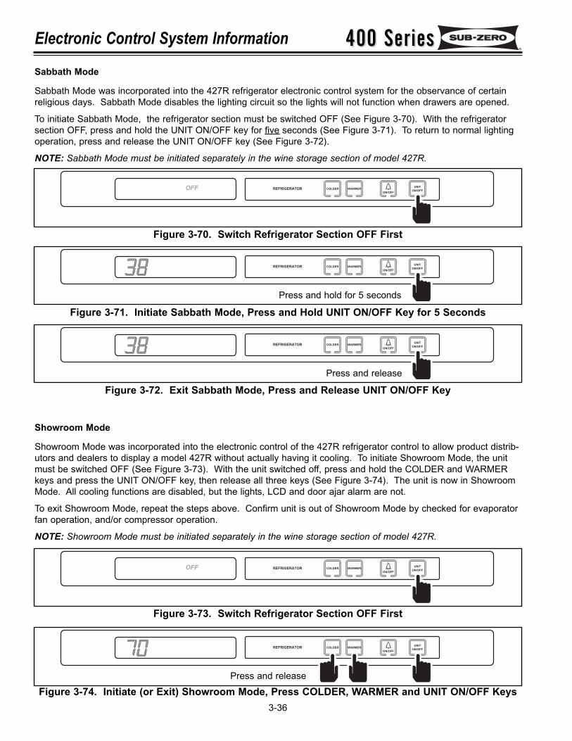
400 Series400 SeriesElectronic Control System Information
3-36Figure 3-74. Initiate (or Exit) Showroom Mode, Press COLDER, WARMER and UNIT ON/OFF Keys
COLDER WARMER
ON/OFF
REFRIGERATORUNIT
ON/OFF
Sabbath Mode
Sabbath Mode was incorporated into the 427R refrigerator electronic control system for the observance of certainreligious days. Sabbath Mode disables the lighting circuit so the lights will not function when drawers are opened.
To initiate Sabbath Mode, the refrigerator section must be switched OFF (See Figure 3-70). With the refrigeratorsection OFF, press and hold the UNIT ON/OFF key for five seconds (See Figure 3-71). To return to normal lightingoperation, press and release the UNIT ON/OFF key (See Figure 3-72).
NOTE: Sabbath Mode must be initiated separately in the wine storage section of model 427R.
Figure 3-70. Switch Refrigerator Section OFF First
Figure 3-71. Initiate Sabbath Mode, Press and Hold UNIT ON/OFF Key for 5 Seconds
Figure 3-72. Exit Sabbath Mode, Press and Release UNIT ON/OFF Key
COLDER WARMER
ON/OFF
REFRIGERATORUNIT
ON/OFFOFF
COLDER WARMER
ON/OFF
REFRIGERATORUNIT
ON/OFF
Press and hold for 5 seconds
Showroom Mode
Showroom Mode was incorporated into the electronic control of the 427R refrigerator control to allow product distrib-utors and dealers to display a model 427R without actually having it cooling. To initiate Showroom Mode, the unitmust be switched OFF (See Figure 3-73). With the unit switched off, press and hold the COLDER and WARMERkeys and press the UNIT ON/OFF key, then release all three keys (See Figure 3-74). The unit is now in ShowroomMode. All cooling functions are disabled, but the lights, LCD and door ajar alarm are not.
To exit Showroom Mode, repeat the steps above. Confirm unit is out of Showroom Mode by checked for evaporatorfan operation, and/or compressor operation.
NOTE: Showroom Mode must be initiated separately in the wine storage section of model 427R.
Figure 3-73. Switch Refrigerator Section OFF First
COLDER WARMER
ON/OFF
REFRIGERATORUNIT
ON/OFFOFF
COLDER WARMER
ON/OFF
REFRIGERATORUNIT
ON/OFF
Press and release
Press and release
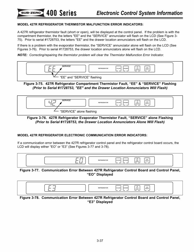
400 Series400 Series Electronic Control System Information
3-37
MODEL 427R REFRIGERATOR THERMISTOR MALFUNCTION ERROR INDICATORS:
A 427R refrigerator thermistor fault (short or open), will be displayed at the control panel. If the problem is with thecompartment thermistor, the the letters "EE" and the “SERVICE” annunciator will flash on the LCD (See Figure 3-75). Prior to serial #1728753, the letters "EE" and the drawer location annunciators will flash on the LCD.
If there is a problem with the evaporator thermistor, the “SERVICE” annunciator alone will flash on the LCD (SeeFigures 3-76). Prior to serial #1728753, the drawer location annunciators alone will flash on the LCD.
NOTE: Correcting/repairing the thermistor problem will clear the Thermistor Malfunction Error Indicator.
Figure 3-76. 427R Refrigerator Evaporator Thermistor Fault, “SERVICE” alone Flashing(Prior to Serial #1728753, the Drawer Location Annunciators Alone Will Flash)
Figure 3-75. 427R Refrigerator Compartment Thermistor Fault, “EE” & “SERVICE” Flashing(Prior to Serial #1728753, "EE" and the Drawer Location Annunciators Will Flash)
COLDER WARMER
ON/OFF
REFRIGERATORUNIT
ON/OFF
SERVICE
“EE” and “SERVICE” flashing
COLDER WARMER
ON/OFF
REFRIGERATORUNIT
ON/OFF
SERVICE
“SERVICE” alone flashing
COLDER WARMER
ON/OFF
REFRIGERATORUNIT
ON/OFF
Figure 3-78. Communication Error Between 427R Refrigerator Control Board and Control Panel,“E3” Displayed
COLDER WARMER
ON/OFF
REFRIGERATORUNIT
ON/OFF
Figure 3-77. Communication Error Between 427R Refrigerator Control Board and Control Panel,“EO” Displayed
MODEL 427R REFRIGERATOR ELECTRONIC COMMUNICATION ERROR INDICATORS:
If a communication error between the 427R refrigerator control panel and the refrigerator control board occurs, theLCD will display either “EO” or “E3” (See Figures 3-77 and 3-78).
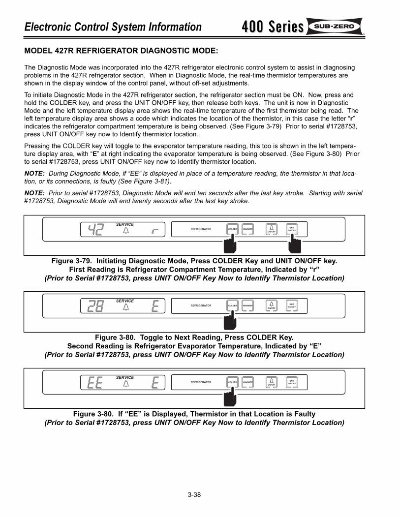
400 Series400 SeriesElectronic Control System Information
3-38
COLDER WARMER
ON/OFF
REFRIGERATORUNIT
ON/OFF
SERVICE
Figure 3-79. Initiating Diagnostic Mode, Press COLDER Key and UNIT ON/OFF key.First Reading is Refrigerator Compartment Temperature, Indicated by “r”
(Prior to Serial #1728753, press UNIT ON/OFF Key Now to Identify Thermistor Location)
MODEL 427R REFRIGERATOR DIAGNOSTIC MODE:
The Diagnostic Mode was incorporated into the 427R refrigerator electronic control system to assist in diagnosingproblems in the 427R refrigerator section. When in Diagnostic Mode, the real-time thermistor temperatures areshown in the display window of the control panel, without off-set adjustments.
To initiate Diagnostic Mode in the 427R refrigerator section, the refrigerator section must be ON. Now, press andhold the COLDER key, and press the UNIT ON/OFF key, then release both keys. The unit is now in DiagnosticMode and the left temperature display area shows the real-time temperature of the first thermistor being read. Theleft temperature display area shows a code which indicates the location of the thermistor, in this case the letter “r”indicates the refrigerator compartment temperature is being observed. (See Figure 3-79) Prior to serial #1728753,press UNIT ON/OFF key now to Identify thermistor location.
Pressing the COLDER key will toggle to the evaporator temperature reading, this too is shown in the left tempera-ture display area, with “E” at right indicating the evaporator temperature is being observed. (See Figure 3-80) Priorto serial #1728753, press UNIT ON/OFF key now to Identify thermistor location.
NOTE: During Diagnostic Mode, if “EE” is displayed in place of a temperature reading, the thermistor in that loca-tion, or its connections, is faulty (See Figure 3-81).
NOTE: Prior to serial #1728753, Diagnostic Mode will end ten seconds after the last key stroke. Starting with serial#1728753, Diagnostic Mode will end twenty seconds after the last key stroke.
COLDER WARMER
ON/OFF
REFRIGERATORUNIT
ON/OFF
SERVICE
Figure 3-80. Toggle to Next Reading, Press COLDER Key.Second Reading is Refrigerator Evaporator Temperature, Indicated by “E”
(Prior to Serial #1728753, press UNIT ON/OFF Key Now to Identify Thermistor Location)
COLDER WARMER
ON/OFF
REFRIGERATORUNIT
ON/OFF
SERVICE
Figure 3-80. If “EE” is Displayed, Thermistor in that Location is Faulty(Prior to Serial #1728753, press UNIT ON/OFF Key Now to Identify Thermistor Location)
400 Series400 Series Sealed System Information
4-1
SECTION 4
SEALED SYSTEMINFORMATION
400 Series400 SeriesSealed System Information
4-2
HFC-134a REFRIGERANT SERVICE INFORMATION:
The 400 Series sealed system contains HFC-134a refrigerant. This section gives some generalrules for working with 134a, and explains procedures to be followed while servicing the sealedsystem.
General Rules for Working with 134a Refrigerant
• Use equipment dedicated to 134a sealed system service only.
• Use only 134a refrigerant for back-flushing and sweep charging.• Always replace the filter-drier when servicing the sealed system.
• The filter-drier must be cut from the sealed system. Never un-braze the drier as the heat willdrive moisture back into the sealed system.
• Do not leave sealed system nor replacement compressor open to the atmosphere for morethan 10 minutes.
• When the rubber plugs are pulled from the service compressor, a release of pressure shouldbe heard. If no release of pressure is heard, do not use the compressor.
• Use ONLY virgin 134a refrigerant when recharging the sealed system.
134a refrigerant requires synthetic Ester oil in the compressor, and does not tolerate contamination fromother refrigerants, moisture, petroleum-based lubricants, silicone lubricants, cleaning compounds, rustinhibitors, leak detection dyes, or any other type of additive.
NOTE: The 427R Refrigerator Sealed System Service Procedures for 134a are the same asthose in the table at right, except for the “NOTE” in the second column of the table.
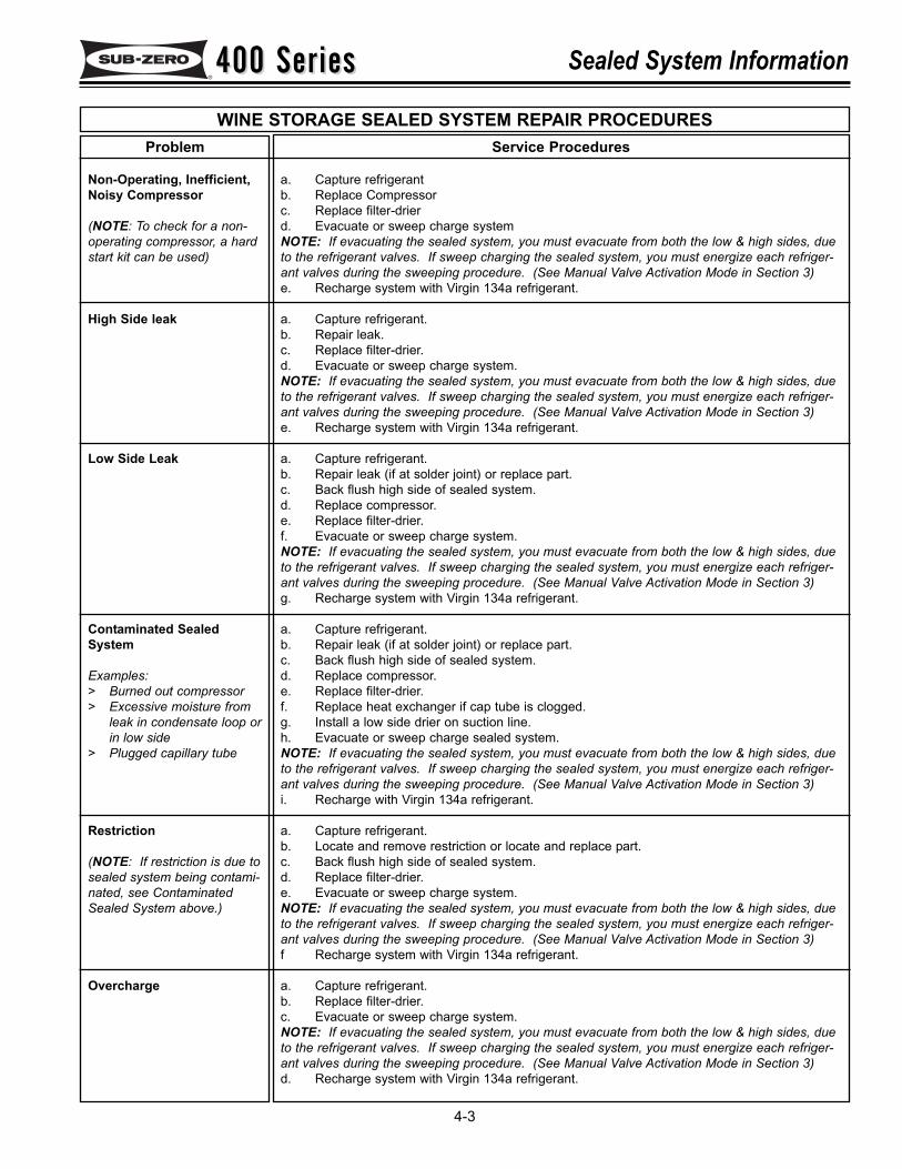
400 Series400 Series Sealed System Information
4-3
WINE STORAGE SEALED SYSTEM REPAIR PROCEDURESService Procedures
a. Capture refrigerantb. Replace Compressorc. Replace filter-drierd. Evacuate or sweep charge systemNOTE: If evacuating the sealed system, you must evacuate from both the low & high sides, dueto the refrigerant valves. If sweep charging the sealed system, you must energize each refriger-ant valves during the sweeping procedure. (See Manual Valve Activation Mode in Section 3) e. Recharge system with Virgin 134a refrigerant.
a. Capture refrigerant.b. Repair leak.c. Replace filter-drier.d. Evacuate or sweep charge system.NOTE: If evacuating the sealed system, you must evacuate from both the low & high sides, dueto the refrigerant valves. If sweep charging the sealed system, you must energize each refriger-ant valves during the sweeping procedure. (See Manual Valve Activation Mode in Section 3) e. Recharge system with Virgin 134a refrigerant.
a. Capture refrigerant.b. Repair leak (if at solder joint) or replace part.c. Back flush high side of sealed system.d. Replace compressor.e. Replace filter-drier.f. Evacuate or sweep charge system.NOTE: If evacuating the sealed system, you must evacuate from both the low & high sides, dueto the refrigerant valves. If sweep charging the sealed system, you must energize each refriger-ant valves during the sweeping procedure. (See Manual Valve Activation Mode in Section 3) g. Recharge system with Virgin 134a refrigerant.
a. Capture refrigerant.b. Repair leak (if at solder joint) or replace part.c. Back flush high side of sealed system.d. Replace compressor.e. Replace filter-drier.f. Replace heat exchanger if cap tube is clogged.g. Install a low side drier on suction line.h. Evacuate or sweep charge sealed system.NOTE: If evacuating the sealed system, you must evacuate from both the low & high sides, dueto the refrigerant valves. If sweep charging the sealed system, you must energize each refriger-ant valves during the sweeping procedure. (See Manual Valve Activation Mode in Section 3) i. Recharge with Virgin 134a refrigerant.
a. Capture refrigerant.b. Locate and remove restriction or locate and replace part.c. Back flush high side of sealed system.d. Replace filter-drier.e. Evacuate or sweep charge system.NOTE: If evacuating the sealed system, you must evacuate from both the low & high sides, dueto the refrigerant valves. If sweep charging the sealed system, you must energize each refriger-ant valves during the sweeping procedure. (See Manual Valve Activation Mode in Section 3) f Recharge system with Virgin 134a refrigerant.
a. Capture refrigerant.b. Replace filter-drier.c. Evacuate or sweep charge system.NOTE: If evacuating the sealed system, you must evacuate from both the low & high sides, dueto the refrigerant valves. If sweep charging the sealed system, you must energize each refriger-ant valves during the sweeping procedure. (See Manual Valve Activation Mode in Section 3) d. Recharge system with Virgin 134a refrigerant.
.
Problem
Non-Operating, Inefficient,Noisy Compressor
(NOTE: To check for a non-operating compressor, a hardstart kit can be used)
High Side leak
Low Side Leak
Contaminated SealedSystem
Examples:> Burned out compressor> Excessive moisture from
leak in condensate loop orin low side
> Plugged capillary tube
Restriction
(NOTE: If restriction is due tosealed system being contami-nated, see ContaminatedSealed System above.)
Overcharge
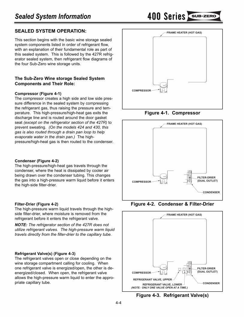
400 Series400 SeriesSealed System Information
4-4
SEALED SYSTEM OPERATION:This section begins with the basic wine storage sealedsystem components listed in order of refrigerant flow,with an explanation of their fundamental role as part ofthis sealed system. This is followed by the 427R refrig-erator sealed system, then refrigerant flow diagrams ofthe four Sub-Zero wine storage units.
The Sub-Zero Wine storage Sealed SystemComponents and Their Role:
Compressor (Figure 4-1)The compressor creates a high side and low side pres-sure difference in the sealed system by compressingthe refrigerant gas, thus raising the pressure and tem-perature. This high-pressure/high-heat gas exits thedischarge line and is routed around the door gasketseat (except on the refrigerator section of the 427R) toprevent sweating. (On the models 424 and 430, thisgas is also routed through a drain pan loop to helpevaporate water in the drain pan.) The high-pressure/high-heat gas is then routed to the condenser.
Condenser (Figure 4-2)The high-pressure/high-heat gas travels through thecondenser, where the heat is dissipated by cooler airbeing drawn over the condenser tubing. This changesthe gas into a high-pressure warm liquid before it entersthe high-side filter-drier.
Filter-Drier (Figure 4-2)The high-pressure warm liquid travels through the high-side filter-drier, where moisture is removed from therefrigerant before it enters the refrigerant valve.NOTE: The refrigerator section of the 427R does notutilize refrigerant valves. The high-pressure warm liquidtravels directly from the filter-drier to the capillary tube.
Refrigerant Valve(s) (Figure 4-3)The refrigerant valves open or close depending on thewine storage compartment calling for cooling. Whenone refrigerant valve is energized/open, the other is de-energized/closed. When open, the refrigerant valveallows the high-pressure warm liquid to enter the appro-priate capillary tube.
Figure 4-1. Compressor
Figure 4-2. Condenser & Filter-Drier
Figure 4-3. Refrigerant Valve(s)
COMPRESSOR
REFRIGERANT VALVE, UPPER
REFRIGERANT VALVE, LOWER CONDENSER
FILTER-DRIER(DUAL OUTLET)
FRAME HEATER (HOT GAS)
(NOTE: ONLY ONE VALVE OPEN AT A TIME.)
COMPRESSOR
CONDENSER
FILTER-DRIER(DUAL OUTLET)
FRAME HEATER (HOT GAS)
COMPRESSOR
FRAME HEATER (HOT GAS)
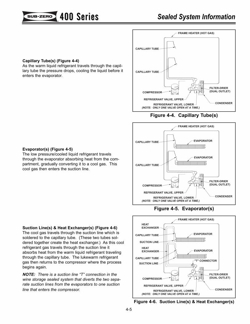
400 Series400 Series Sealed System Information
4-5
Capillary Tube(s) (Figure 4-4)As the warm liquid refrigerant travels through the capil-lary tube the pressure drops, cooling the liquid before itenters the evaporator.
Evaporator(s) (Figure 4-5)The low pressure/cooled liquid refrigerant travelsthrough the evaporator absorbing heat from the com-partment, gradually converting it to a cool gas. Thiscool gas then enters the suction line.
Suction Line(s) & Heat Exchanger(s) (Figure 4-6)The cool gas travels through the suction line which issoldered to the capillary tube. (These two tubes sol-dered together create the heat exchanger.) As this coolrefrigerant gas travels through the suction line itabsorbs heat from the warm liquid refrigerant travelingthrough the capillary tube. The lukewarm refrigerantgas then returns to the compressor where the processbegins again.
NOTE: There is a suction line “T” connection in thewine storage sealed system that diverts the two sepa-rate suction lines from the evaporators to one suctionline that enters the compressor.
Figure 4-4. Capillary Tube(s)
Figure 4-5. Evaporator(s)
Figure 4-6. Suction Line(s) & Heat Exchanger(s)
COMPRESSOR
REFRIGERANT VALVE, UPPER
REFRIGERANT VALVE, LOWER CONDENSER
FILTER-DRIER(DUAL OUTLET)
EVAPORATOR
EVAPORATOR
FRAME HEATER (HOT GAS)
HEATEXCHANGER
CAPILLARY TUBE
CAPILLARY TUBE
HEATEXCHANGER
SUCTION LINE
SUCTION LINE
(NOTE: ONLY ONE VALVE OPEN AT A TIME.)
"T" CONNECTOR
COMPRESSOR
REFRIGERANT VALVE, UPPER
REFRIGERANT VALVE, LOWER CONDENSER
FILTER-DRIER(DUAL OUTLET)
EVAPORATOR
EVAPORATOR
FRAME HEATER (HOT GAS)
CAPILLARY TUBE
CAPILLARY TUBE
(NOTE: ONLY ONE VALVE OPEN AT A TIME.)
COMPRESSOR
REFRIGERANT VALVE, UPPER
REFRIGERANT VALVE, LOWER CONDENSER
FILTER-DRIER(DUAL OUTLET)
FRAME HEATER (HOT GAS)
CAPILLARY TUBE
CAPILLARY TUBE
(NOTE: ONLY ONE VALVE OPEN AT A TIME.)
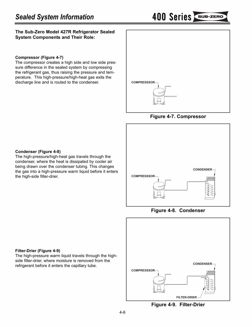
400 Series400 SeriesSealed System Information
4-6
The Sub-Zero Model 427R Refrigerator SealedSystem Components and Their Role:
Compressor (Figure 4-7)The compressor creates a high side and low side pres-sure difference in the sealed system by compressingthe refrigerant gas, thus raising the pressure and tem-perature. This high-pressure/high-heat gas exits thedischarge line and is routed to the condenser.
Condenser (Figure 4-8)The high-pressure/high-heat gas travels through thecondenser, where the heat is dissipated by cooler airbeing drawn over the condenser tubing. This changesthe gas into a high-pressure warm liquid before it entersthe high-side filter-drier.
Filter-Drier (Figure 4-9)The high-pressure warm liquid travels through the high-side filter-drier, where moisture is removed from therefrigerant before it enters the capillary tube.
Figure 4-7. Compressor
Figure 4-8. Condenser
Figure 4-9. Filter-Drier
CONDENSER
FILTER-DRIER
COMPRESSSOR
CONDENSER
COMPRESSSOR
COMPRESSSOR
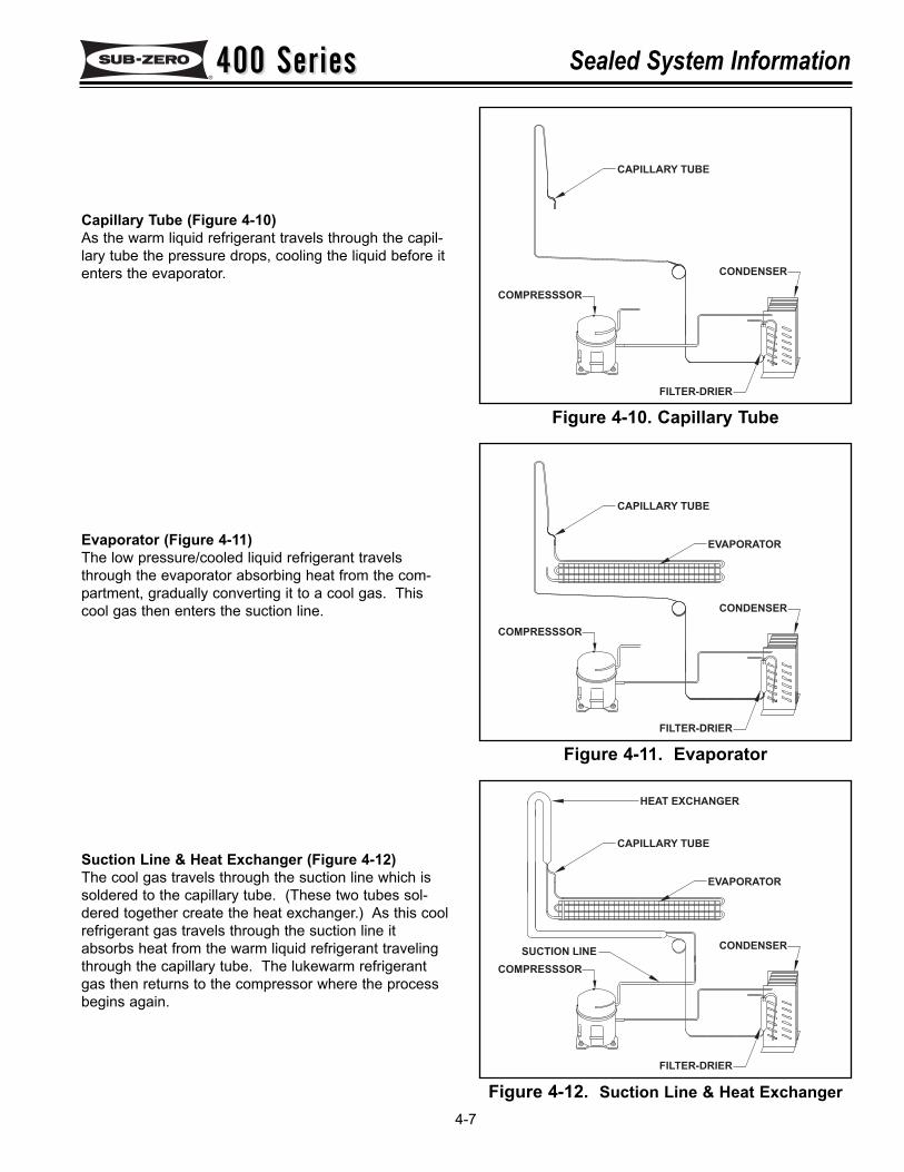
400 Series400 Series Sealed System Information
4-7
Capillary Tube (Figure 4-10)As the warm liquid refrigerant travels through the capil-lary tube the pressure drops, cooling the liquid before itenters the evaporator.
Evaporator (Figure 4-11)The low pressure/cooled liquid refrigerant travelsthrough the evaporator absorbing heat from the com-partment, gradually converting it to a cool gas. Thiscool gas then enters the suction line.
Suction Line & Heat Exchanger (Figure 4-12)The cool gas travels through the suction line which issoldered to the capillary tube. (These two tubes sol-dered together create the heat exchanger.) As this coolrefrigerant gas travels through the suction line itabsorbs heat from the warm liquid refrigerant travelingthrough the capillary tube. The lukewarm refrigerantgas then returns to the compressor where the processbegins again.
Figure 4-10. Capillary Tube
Figure 4-11. Evaporator
Figure 4-12. Suction Line & Heat Exchanger
CONDENSER
FILTER-DRIER
SUCTION LINECOMPRESSSOR
EVAPORATOR
CAPILLARY TUBE
HEAT EXCHANGER
CONDENSER
FILTER-DRIER
COMPRESSSOR
EVAPORATOR
CAPILLARY TUBE
CONDENSER
FILTER-DRIER
COMPRESSSOR
CAPILLARY TUBE
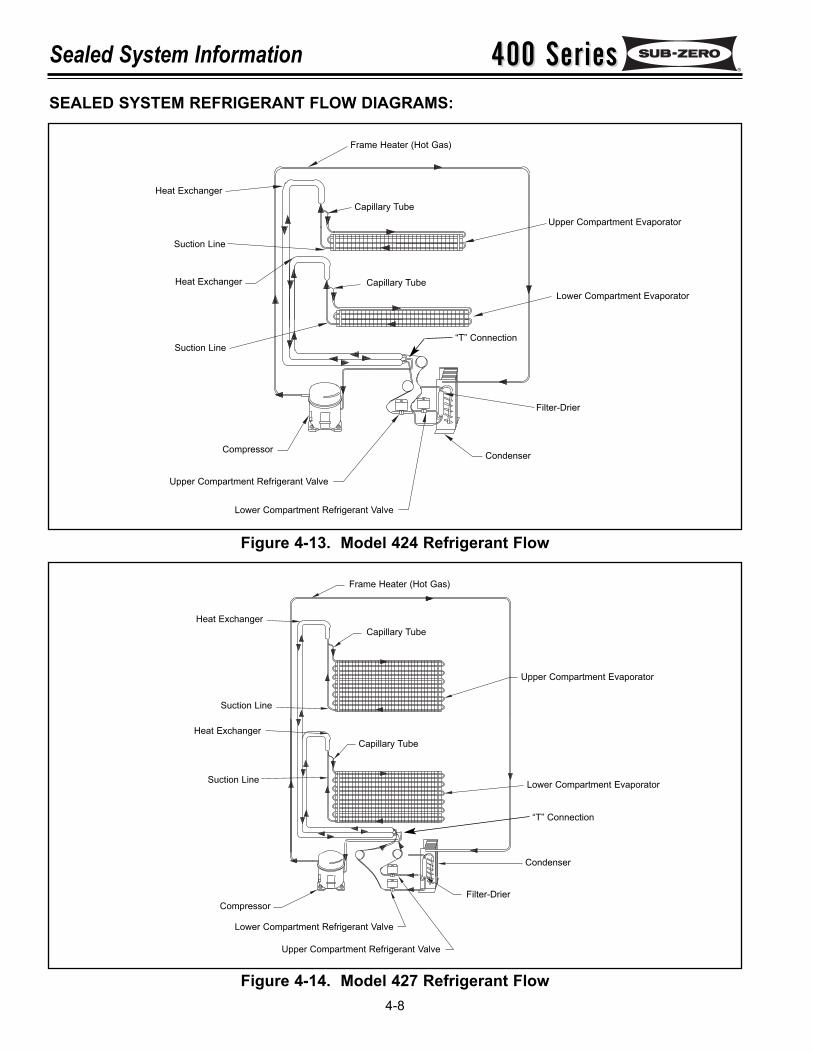
400 Series400 SeriesSealed System Information
4-8
SEALED SYSTEM REFRIGERANT FLOW DIAGRAMS:
Figure 4-13. Model 424 Refrigerant Flow
Figure 4-14. Model 427 Refrigerant Flow
Condenser
Upper Compartment Refrigerant Valve
Lower Compartment Refrigerant Valve
Compressor
Capillary TubeHeat Exchanger
Capillary Tube
Frame Heater (Hot Gas)
Suction Line
Suction Line
Frame Heater (Hot Gas)
Suction Line
Suction Line
Heat Exchanger
Heat Exchanger
Heat Exchanger
Capillary Tube
Capillary Tube
Upper Compartment Evaporator
Lower Compartment Evaporator
Upper Compartment Evaporator
Lower Compartment Evaporator
Compressor
Condenser
Upper Compartment Refrigerant Valve
Lower Compartment Refrigerant Valve
Filter-Drier
Filter-Drier
“T” Connection
“T” Connection
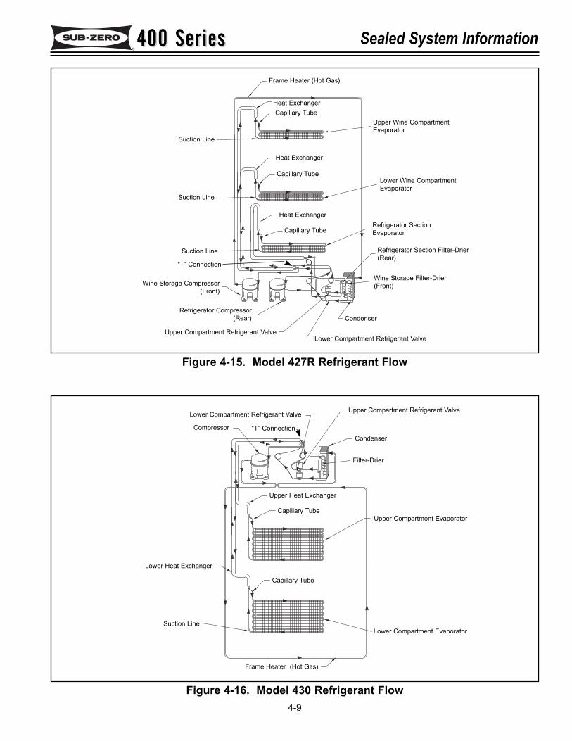
400 Series400 Series Sealed System Information
4-9
Figure 4-15. Model 427R Refrigerant Flow
Figure 4-16. Model 430 Refrigerant Flow
Upper Compartment Refrigerant ValveLower Compartment Refrigerant Valve
CompressorCondenser
Filter-Drier
Upper Compartment Evaporator
Lower Compartment Evaporator
Frame Heater (Hot Gas)
Suction Line
Lower Heat Exchanger
Upper Heat Exchanger
Capillary Tube
Capillary Tube
Condenser
Upper Compartment Refrigerant ValveLower Compartment Refrigerant Valve
Wine Storage Compressor(Front)
Refrigerator Compressor(Rear)
Capillary Tube
Capillary Tube
Heat Exchanger
Heat Exchanger
Heat Exchanger
Wine Storage Filter-Drier(Front)
Refrigerator Section Filter-Drier(Rear)
Refrigerator SectionEvaporator
Lower Wine CompartmentEvaporator
Upper Wine CompartmentEvaporator
Capillary Tube
Frame Heater (Hot Gas)
Suction Line
Suction Line
Suction Line
“T” Connection
“T” Connection
400 Series400 SeriesSealed System Information Notes
4-10
400 Series400 Series Air Flow & Fan Blade Spacing
5-1
SECTION 5
AIR FLOW &FAN BLADE SPACING
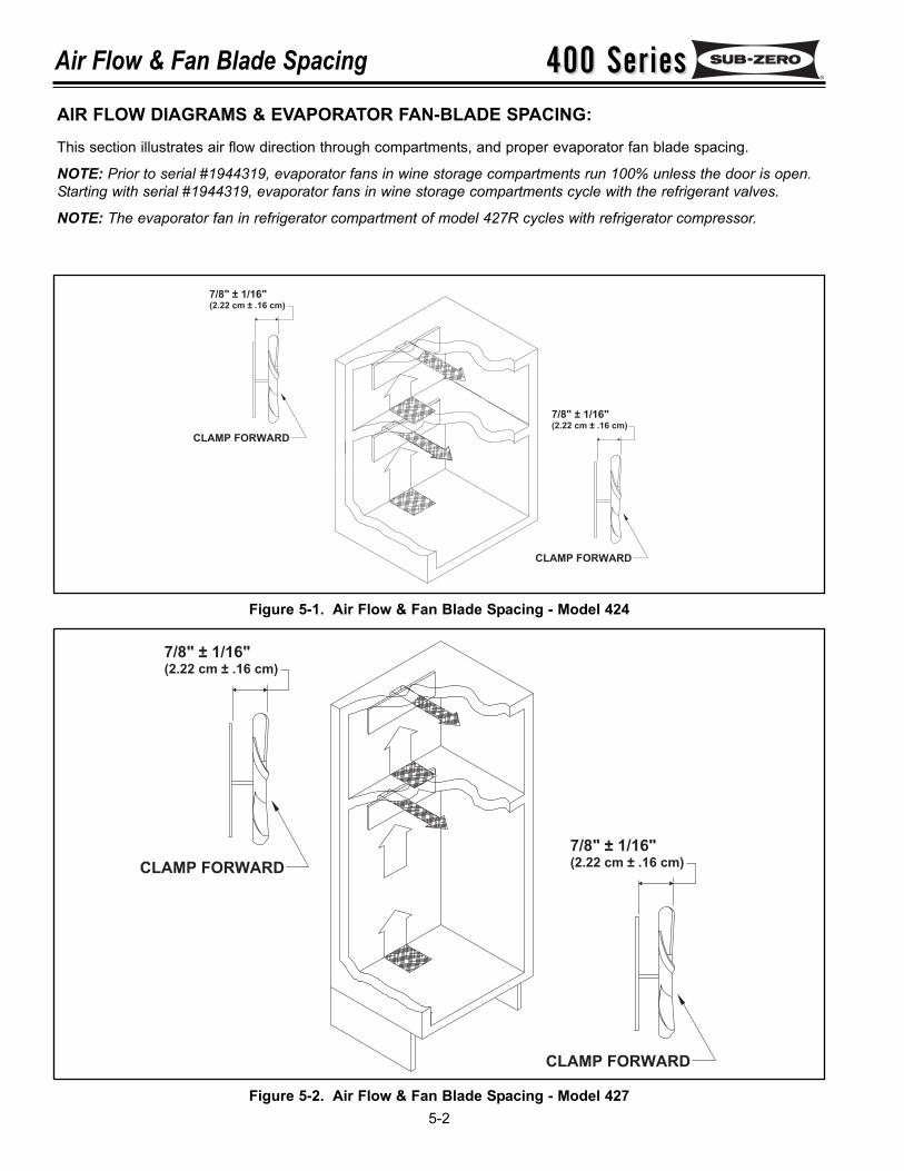
400 Series400 SeriesAir Flow & Fan Blade Spacing
5-2
7/8" ± 1/16"(2.22 cm ± .16 cm)
CLAMP FORWARD
7/8" ± 1/16"(2.22 cm ± .16 cm)
CLAMP FORWARD
7/8" ± 1/16"(2.22 cm ± .16 cm)
CLAMP FORWARD
7/8" ± 1/16"(2.22 cm ± .16 cm)
CLAMP FORWARD
Figure 5-1. Air Flow & Fan Blade Spacing - Model 424
Figure 5-2. Air Flow & Fan Blade Spacing - Model 427
AIR FLOW DIAGRAMS & EVAPORATOR FAN-BLADE SPACING:This section illustrates air flow direction through compartments, and proper evaporator fan blade spacing.
NOTE: Prior to serial #1944319, evaporator fans in wine storage compartments run 100% unless the door is open.Starting with serial #1944319, evaporator fans in wine storage compartments cycle with the refrigerant valves.
NOTE: The evaporator fan in refrigerator compartment of model 427R cycles with refrigerator compressor.
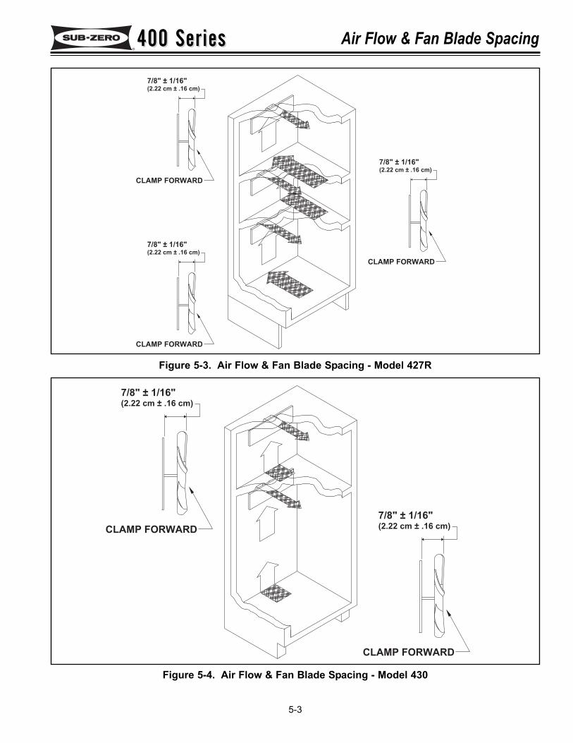
400 Series400 Series Air Flow & Fan Blade Spacing
5-3
7/8" ± 1/16"(2.22 cm ± .16 cm)
CLAMP FORWARD
7/8" ± 1/16"(2.22 cm ± .16 cm)
CLAMP FORWARD
7/8" ± 1/16"(2.22 cm ± .16 cm)
CLAMP FORWARD
7/8" ± 1/16"(2.22 cm ± .16 cm)
CLAMP FORWARD
7/8" ± 1/16"(2.22 cm ± .16 cm)
CLAMP FORWARD
Figure 5-3. Air Flow & Fan Blade Spacing - Model 427R
Figure 5-4. Air Flow & Fan Blade Spacing - Model 430
400 Series400 SeriesAir Flow & Fan Blade Spacing Notes
5-4
400 Series400 Series Component Access and Removal
6-1
SECTION 6
COMPONENT REMOVAL
400 Series400 SeriesComponent Access and Removal
6-2
COMPONENT ACCESS AND REMOVAL:This section explains how to access and remove components on / in a 400 Series unit. Due to the diversity of the400 Series, this section is divided into three sub-sections with the model 424 being covered first, followed by themodels 427 and 427R, and the third sub-section covers the model 430. In each of the three sub-sections you willfind access and removal instructions for the external cosmetic and mechanical components, followed by the interiorcosmetic components, the interior mechanical components and the sealed system components.Before continuing, please take note of the WARNINGS and CAUTIONS below.
IF IT IS NECESSARY TO REMOVE A UNIT FROM ITS INSTALLATION, REMEMBER THAT THE UNIT COULDTIP FORWARD WHEN PULLED FORWARD, BEYOND THE ANTI-TIP COMPONENTS, RESULTING IN SERIOUSINJURY OR DEATH. PULLING A UNIT FROM ITS INSTALLATION SHOULD ONLY BE PERFORMED BY ANAUTHORIZED SERVICE TECHNICIAN OR INSTALLER.
TO AVOID ELECTRIC SHOCK, POWER TO THE UNIT MUST BE DISCONNECTED WHENEVER ACCESSINGAND/OR REMOVING COMPONENTS POWERED BY ELECTRICITY OR COMPONENTS NEAR OTHER ELEC-TRICAL COMPONENTS.
When removing or disconnecting door closers and/or hInge assemblies, remember they are spring loadedand may recoil quickly when released.
To avoid static electric damage to the control board, always handle the board by the edges.
When working in the compressor area, remember that compressor and tubing could be hot.
When working on or around evaporator or condenser, remember evaporator and condenser fins are sharp.
WHEN REMOVING A DOOR FROM A UNIT, REMEMBER THAT DOORS ARE HEAVY. IF A DOOR WERE TOFALL , IT COULD CAUSE SERIOUS PERSONAL INJURY.
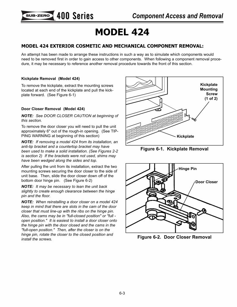
400 Series400 Series Component Access and Removal
6-3
MODEL 424MODEL 424 EXTERIOR COSMETIC AND MECHANICAL COMPONENT REMOVAL:
An attempt has been made to arrange these instructions in such a way as to simulate which components wouldneed to be removed first in order to gain access to other components. When following a component removal proce-dure, it may be necessary to reference another removal procedure towards the front of this section.
Figure 6-1. Kickplate Removal
Kickplate
KickplateMounting
Screw(1 of 2)
Figure 6-2. Door Closer Removal
Door Closer
Hinge Pin
Kickplate Removal (Model 424)
To remove the kickplate, extract the mounting screwslocated at each end of the kickplate and pull the kick-plate forward. (See Figure 6-1)
Door Closer Removal (Model 424)
NOTE: See DOOR CLOSER CAUTION at beginning ofthis section.To remove the door closer you will need to pull the unitapproximately 6" out of the rough-in opening. (See TIP-PING WARNING at beginning of this section)NOTE: If removing a model 424 from its installation, ananti-tip bracket and a countertop bracket may havebeen used to make a solid installation. (See Figures 2-2is section 2) If the brackets were not used, shims mayhave been wedged along the sides and top.After pulling the unit from its installation, extract the twomounting screws securing the door closer to the side ofunit base. Then, slide the door closer down off of thebottom door hinge pin. (See Figure 6-2) NOTE: It may be necessary to lean the unit backslightly to create enough clearance between the hingepin and the floor.NOTE: When reinstalling a door closer on a model 424keep in mind that there are slots in the cam of the doorcloser that must line-up with the ribs on the hinge pin.Also, the cams may be in "full-closed position" or "full -open position." It is easiest to install a door closer ontothe hinge pin with the door closed and the cams in the"full-open position." Then, after the closer is on thehinge pin, rotate the closer to the closed position andinstall the screws.
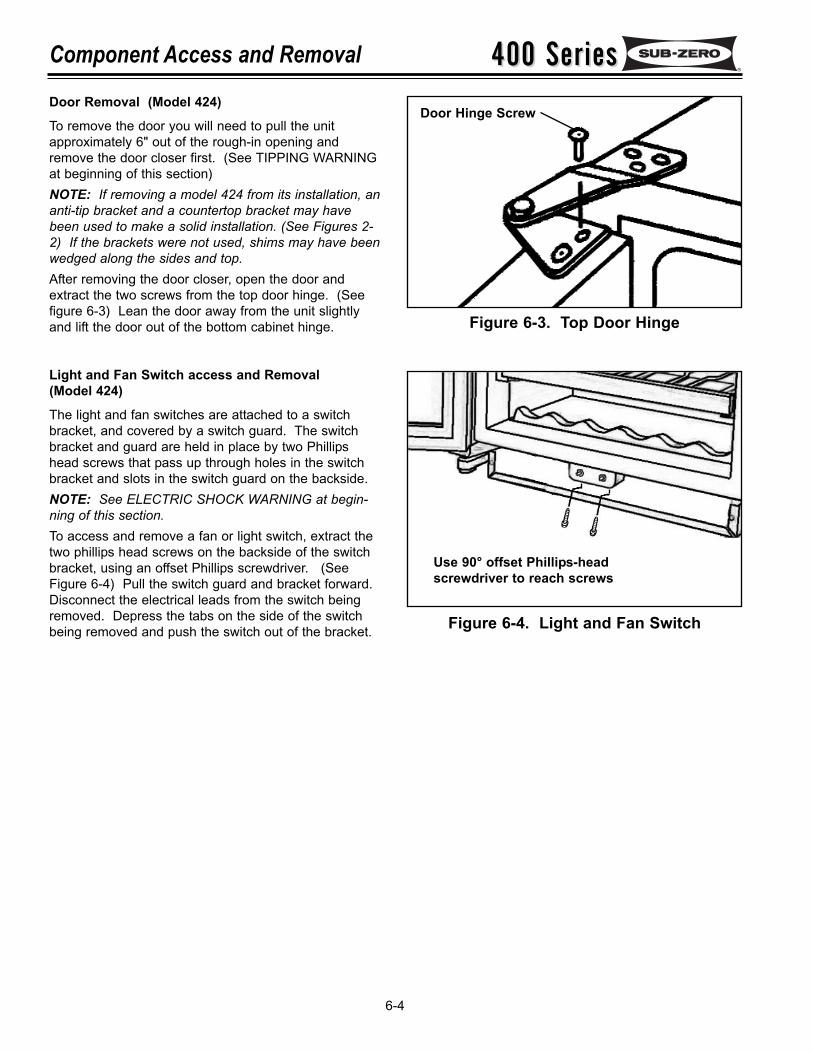
400 Series400 SeriesComponent Access and Removal
6-4
Door Removal (Model 424)
To remove the door you will need to pull the unitapproximately 6" out of the rough-in opening andremove the door closer first. (See TIPPING WARNINGat beginning of this section)NOTE: If removing a model 424 from its installation, ananti-tip bracket and a countertop bracket may havebeen used to make a solid installation. (See Figures 2-2) If the brackets were not used, shims may have beenwedged along the sides and top.After removing the door closer, open the door andextract the two screws from the top door hinge. (Seefigure 6-3) Lean the door away from the unit slightlyand lift the door out of the bottom cabinet hinge.
Light and Fan Switch access and Removal(Model 424)
The light and fan switches are attached to a switchbracket, and covered by a switch guard. The switchbracket and guard are held in place by two Phillipshead screws that pass up through holes in the switchbracket and slots in the switch guard on the backside.NOTE: See ELECTRIC SHOCK WARNING at begin-ning of this section.To access and remove a fan or light switch, extract thetwo phillips head screws on the backside of the switchbracket, using an offset Phillips screwdriver. (SeeFigure 6-4) Pull the switch guard and bracket forward.Disconnect the electrical leads from the switch beingremoved. Depress the tabs on the side of the switchbeing removed and push the switch out of the bracket.
Figure 6-3. Top Door Hinge
Figure 6-4. Light and Fan Switch
Door Hinge Screw
Use 90° offset Phillips-headscrewdriver to reach screws
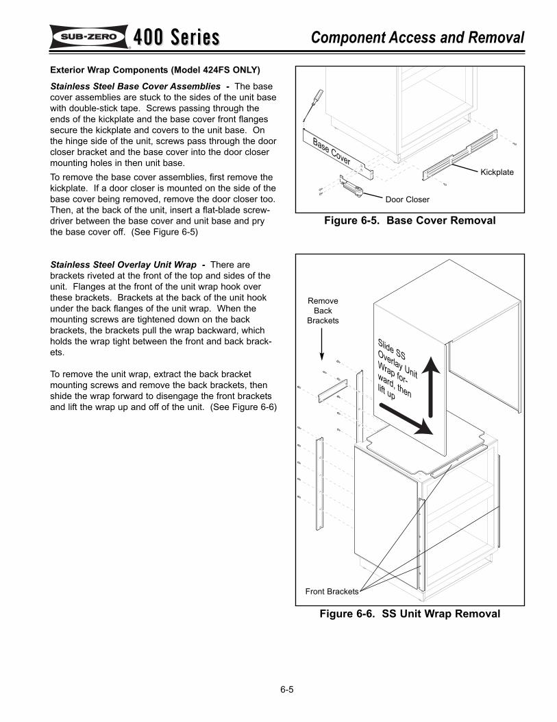
400 Series400 Series Component Access and Removal
6-5
Exterior Wrap Components (Model 424FS ONLY)
Stainless Steel Base Cover Assemblies - The basecover assemblies are stuck to the sides of the unit basewith double-stick tape. Screws passing through theends of the kickplate and the base cover front flangessecure the kickplate and covers to the unit base. Onthe hinge side of the unit, screws pass through the doorcloser bracket and the base cover into the door closermounting holes in then unit base.To remove the base cover assemblies, first remove thekickplate. If a door closer is mounted on the side of thebase cover being removed, remove the door closer too.Then, at the back of the unit, insert a flat-blade screw-driver between the base cover and unit base and prythe base cover off. (See Figure 6-5)
Stainless Steel Overlay Unit Wrap - There arebrackets riveted at the front of the top and sides of theunit. Flanges at the front of the unit wrap hook overthese brackets. Brackets at the back of the unit hookunder the back flanges of the unit wrap. When themounting screws are tightened down on the backbrackets, the brackets pull the wrap backward, whichholds the wrap tight between the front and back brack-ets.
To remove the unit wrap, extract the back bracketmounting screws and remove the back brackets, thenshide the wrap forward to disengage the front bracketsand lift the wrap up and off of the unit. (See Figure 6-6)
Kickplate
Door Closer
Base Cover
Figure 6-5. Base Cover Removal
Figure 6-6. SS Unit Wrap Removal
Slide SSOverlay UnitWrap for-ward, thenlift up
Front Brackets
RemoveBack
Brackets
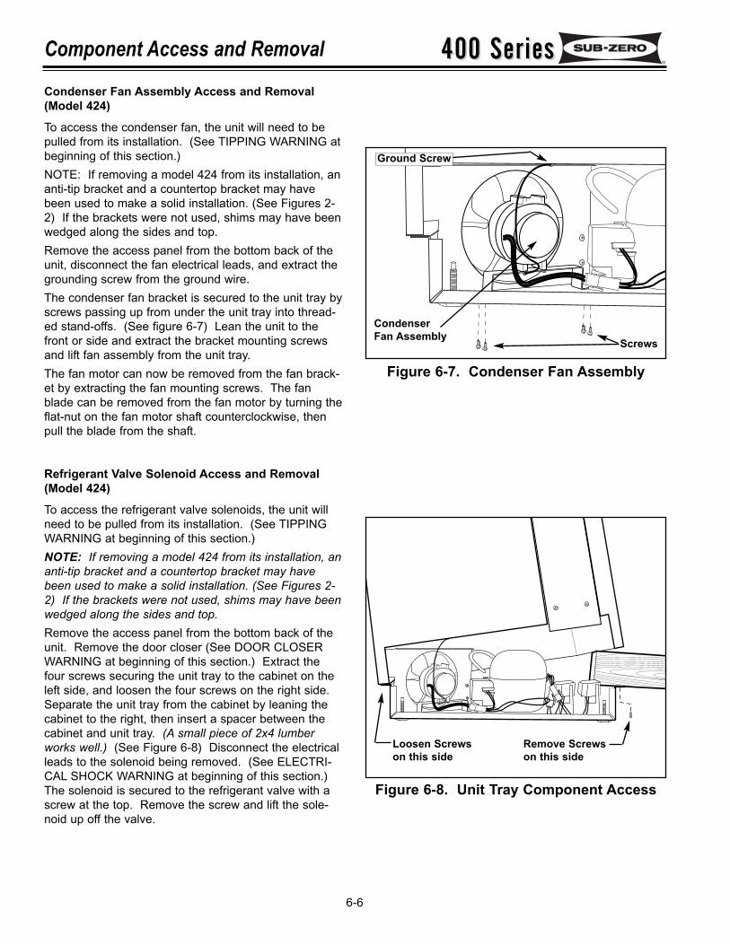
400 Series400 SeriesComponent Access and Removal
6-6
Condenser Fan Assembly Access and Removal(Model 424)
To access the condenser fan, the unit will need to bepulled from its installation. (See TIPPING WARNING atbeginning of this section.)NOTE: If removing a model 424 from its installation, ananti-tip bracket and a countertop bracket may havebeen used to make a solid installation. (See Figures 2-2) If the brackets were not used, shims may have beenwedged along the sides and top.Remove the access panel from the bottom back of theunit, disconnect the fan electrical leads, and extract thegrounding screw from the ground wire.The condenser fan bracket is secured to the unit tray byscrews passing up from under the unit tray into thread-ed stand-offs. (See figure 6-7) Lean the unit to thefront or side and extract the bracket mounting screwsand lift fan assembly from the unit tray.The fan motor can now be removed from the fan brack-et by extracting the fan mounting screws. The fanblade can be removed from the fan motor by turning theflat-nut on the fan motor shaft counterclockwise, thenpull the blade from the shaft.
Refrigerant Valve Solenoid Access and Removal(Model 424)
To access the refrigerant valve solenoids, the unit willneed to be pulled from its installation. (See TIPPINGWARNING at beginning of this section.)NOTE: If removing a model 424 from its installation, ananti-tip bracket and a countertop bracket may havebeen used to make a solid installation. (See Figures 2-2) If the brackets were not used, shims may have beenwedged along the sides and top.Remove the access panel from the bottom back of theunit. Remove the door closer (See DOOR CLOSERWARNING at beginning of this section.) Extract thefour screws securing the unit tray to the cabinet on theleft side, and loosen the four screws on the right side.Separate the unit tray from the cabinet by leaning thecabinet to the right, then insert a spacer between thecabinet and unit tray. (A small piece of 2x4 lumberworks well.) (See Figure 6-8) Disconnect the electricalleads to the solenoid being removed. (See ELECTRI-CAL SHOCK WARNING at beginning of this section.)The solenoid is secured to the refrigerant valve with ascrew at the top. Remove the screw and lift the sole-noid up off the valve.
Figure 6-7. Condenser Fan Assembly
Figure 6-8. Unit Tray Component Access
Screws
Ground Screw
CondenserFan Assembly
Loosen Screwson this side
Remove Screwson this side
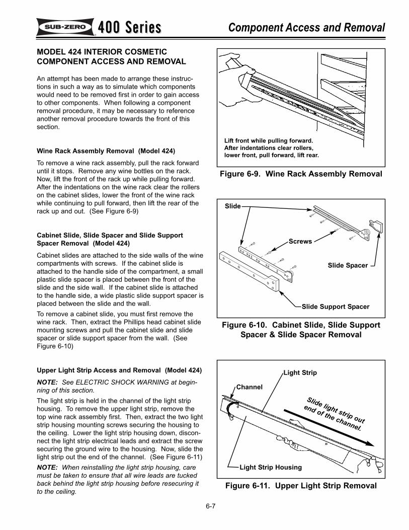
400 Series400 Series Component Access and Removal
6-7
Figure 6-9. Wine Rack Assembly Removal
Figure 6-10. Cabinet Slide, Slide SupportSpacer & Slide Spacer Removal
Figure 6-11. Upper Light Strip Removal
MODEL 424 INTERIOR COSMETIC COMPONENT ACCESS AND REMOVAL
An attempt has been made to arrange these instruc-tions in such a way as to simulate which componentswould need to be removed first in order to gain accessto other components. When following a componentremoval procedure, it may be necessary to referenceanother removal procedure towards the front of thissection.
Wine Rack Assembly Removal (Model 424)
To remove a wine rack assembly, pull the rack forwarduntil it stops. Remove any wine bottles on the rack.Now, lift the front of the rack up while pulling forward.After the indentations on the wine rack clear the rollerson the cabinet slides, lower the front of the wine rackwhile continuing to pull forward, then lift the rear of therack up and out. (See Figure 6-9)
Cabinet Slide, Slide Spacer and Slide SupportSpacer Removal (Model 424)
Cabinet slides are attached to the side walls of the winecompartments with screws. If the cabinet slide isattached to the handle side of the compartment, a smallplastic slide spacer is placed between the front of theslide and the side wall. If the cabinet slide is attachedto the handle side, a wide plastic slide support spacer isplaced between the slide and the wall.To remove a cabinet slide, you must first remove thewine rack. Then, extract the Phillips head cabinet slidemounting screws and pull the cabinet slide and slidespacer or slide support spacer from the wall. (SeeFigure 6-10)
Upper Light Strip Access and Removal (Model 424)
NOTE: See ELECTRIC SHOCK WARNING at begin-ning of this section.The light strip is held in the channel of the light striphousing. To remove the upper light strip, remove thetop wine rack assembly first. Then, extract the two lightstrip housing mounting screws securing the housing tothe ceiling. Lower the light strip housing down, discon-nect the light strip electrical leads and extract the screwsecuring the ground wire to the housing. Now, slide thelight strip out the end of the channel. (See Figure 6-11)NOTE: When reinstalling the light strip housing, caremust be taken to ensure that all wire leads are tuckedback behind the light strip housing before resecuring itto the ceiling.
Lift front while pulling forward.After indentations clear rollers,lower front, pull forward, lift rear.
Slide Support Spacer
Slide
Screws
Slide light strip out
end of the channel.
Channel
Light Strip
Light Strip Housing
Slide Spacer
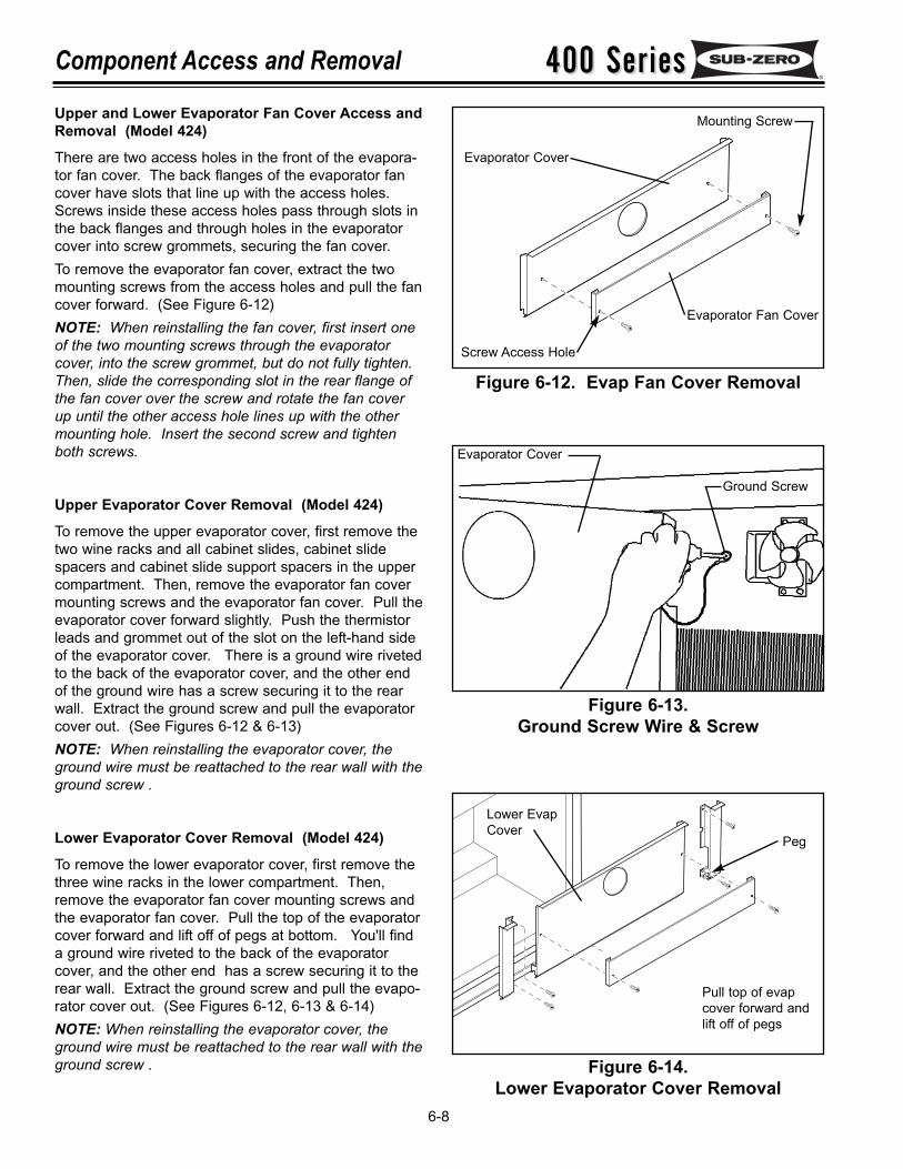
400 Series400 SeriesComponent Access and Removal
6-8
Upper and Lower Evaporator Fan Cover Access andRemoval (Model 424)
There are two access holes in the front of the evapora-tor fan cover. The back flanges of the evaporator fancover have slots that line up with the access holes.Screws inside these access holes pass through slots inthe back flanges and through holes in the evaporatorcover into screw grommets, securing the fan cover.To remove the evaporator fan cover, extract the twomounting screws from the access holes and pull the fancover forward. (See Figure 6-12)NOTE: When reinstalling the fan cover, first insert oneof the two mounting screws through the evaporatorcover, into the screw grommet, but do not fully tighten.Then, slide the corresponding slot in the rear flange ofthe fan cover over the screw and rotate the fan coverup until the other access hole lines up with the othermounting hole. Insert the second screw and tightenboth screws.
Upper Evaporator Cover Removal (Model 424)
To remove the upper evaporator cover, first remove thetwo wine racks and all cabinet slides, cabinet slidespacers and cabinet slide support spacers in the uppercompartment. Then, remove the evaporator fan covermounting screws and the evaporator fan cover. Pull theevaporator cover forward slightly. Push the thermistorleads and grommet out of the slot on the left-hand sideof the evaporator cover. There is a ground wire rivetedto the back of the evaporator cover, and the other endof the ground wire has a screw securing it to the rearwall. Extract the ground screw and pull the evaporatorcover out. (See Figures 6-12 & 6-13)NOTE: When reinstalling the evaporator cover, theground wire must be reattached to the rear wall with theground screw .
Lower Evaporator Cover Removal (Model 424)
To remove the lower evaporator cover, first remove thethree wine racks in the lower compartment. Then,remove the evaporator fan cover mounting screws andthe evaporator fan cover. Pull the top of the evaporatorcover forward and lift off of pegs at bottom. You'll finda ground wire riveted to the back of the evaporatorcover, and the other end has a screw securing it to therear wall. Extract the ground screw and pull the evapo-rator cover out. (See Figures 6-12, 6-13 & 6-14)NOTE: When reinstalling the evaporator cover, theground wire must be reattached to the rear wall with theground screw .
Figure 6-12. Evap Fan Cover Removal
Figure 6-13.Ground Screw Wire & Screw
Figure 6-14.Lower Evaporator Cover Removal
Evaporator Fan Cover
Screw Access Hole
Evaporator Cover
Ground Screw
Evaporator Cover
Mounting Screw
Pull top of evapcover forward andlift off of pegs
Lower EvapCover
Peg
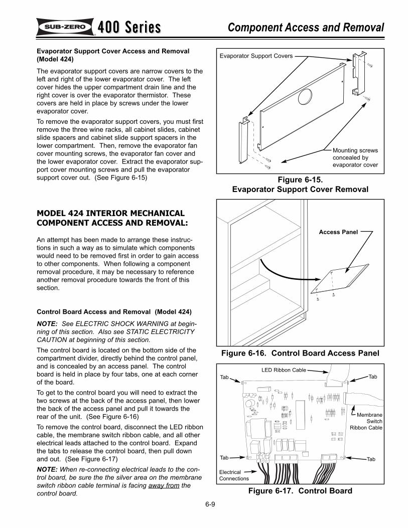
400 Series400 Series Component Access and Removal
6-9
Evaporator Support Cover Access and Removal(Model 424)
The evaporator support covers are narrow covers to theleft and right of the lower evaporator cover. The leftcover hides the upper compartment drain line and theright cover is over the evaporator thermistor. Thesecovers are held in place by screws under the lowerevaporator cover.To remove the evaporator support covers, you must firstremove the three wine racks, all cabinet slides, cabinetslide spacers and cabinet slide support spacers in thelower compartment. Then, remove the evaporator fancover mounting screws, the evaporator fan cover andthe lower evaporator cover. Extract the evaporator sup-port cover mounting screws and pull the evaporatorsupport cover out. (See Figure 6-15) Figure 6-15.
Evaporator Support Cover Removal
MODEL 424 INTERIOR MECHANICAL COMPONENT ACCESS AND REMOVAL:
An attempt has been made to arrange these instruc-tions in such a way as to simulate which componentswould need to be removed first in order to gain accessto other components. When following a componentremoval procedure, it may be necessary to referenceanother removal procedure towards the front of thissection.
Control Board Access and Removal (Model 424)
NOTE: See ELECTRIC SHOCK WARNING at begin-ning of this section. Also see STATIC ELECTRICITYCAUTION at beginning of this section.The control board is located on the bottom side of thecompartment divider, directly behind the control panel,and is concealed by an access panel. The controlboard is held in place by four tabs, one at each cornerof the board.To get to the control board you will need to extract thetwo screws at the back of the access panel, then lowerthe back of the access panel and pull it towards therear of the unit. (See Figure 6-16)To remove the control board, disconnect the LED ribboncable, the membrane switch ribbon cable, and all otherelectrical leads attached to the control board. Expandthe tabs to release the control board, then pull downand out. (See Figure 6-17)NOTE: When re-connecting electrical leads to the con-trol board, be sure the the silver area on the membraneswitch ribbon cable terminal is facing away from thecontrol board.
Figure 6-16. Control Board Access Panel
Figure 6-17. Control Board
Evaporator Support Covers
Mounting screws concealed by evaporator cover
Tab
LED Ribbon Cable
MembraneSwitch
Ribbon Cable
ElectricalConnections
Tab
TabTab
Access Panel
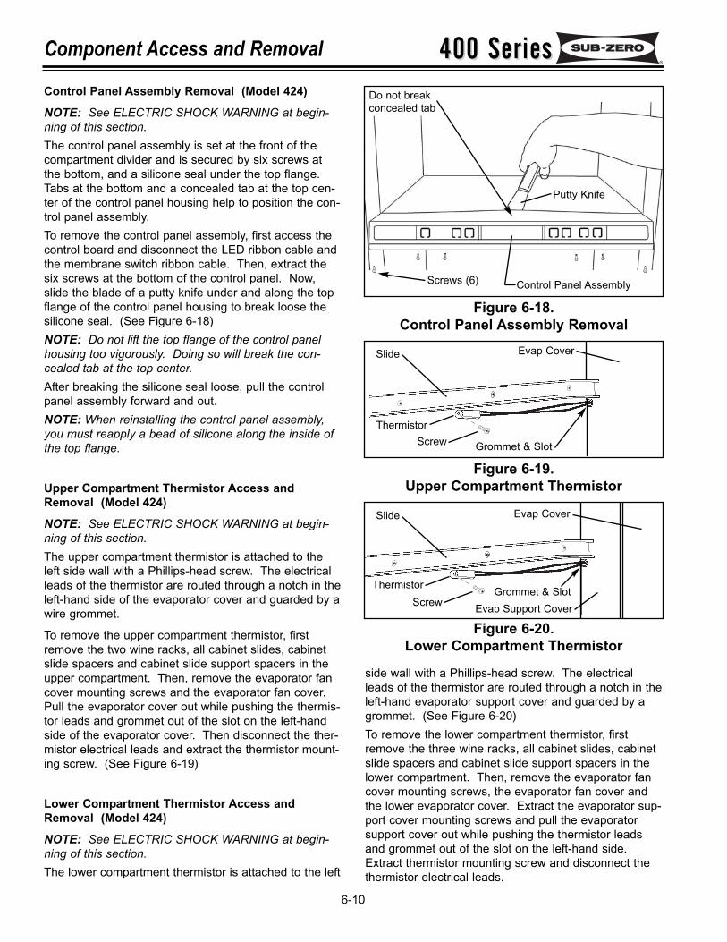
400 Series400 SeriesComponent Access and Removal
6-10
Control Panel Assembly Removal (Model 424)
NOTE: See ELECTRIC SHOCK WARNING at begin-ning of this section.The control panel assembly is set at the front of thecompartment divider and is secured by six screws atthe bottom, and a silicone seal under the top flange.Tabs at the bottom and a concealed tab at the top cen-ter of the control panel housing help to position the con-trol panel assembly.To remove the control panel assembly, first access thecontrol board and disconnect the LED ribbon cable andthe membrane switch ribbon cable. Then, extract thesix screws at the bottom of the control panel. Now,slide the blade of a putty knife under and along the topflange of the control panel housing to break loose thesilicone seal. (See Figure 6-18)NOTE: Do not lift the top flange of the control panelhousing too vigorously. Doing so will break the con-cealed tab at the top center.After breaking the silicone seal loose, pull the controlpanel assembly forward and out.NOTE: When reinstalling the control panel assembly,you must reapply a bead of silicone along the inside ofthe top flange.
Upper Compartment Thermistor Access andRemoval (Model 424)
NOTE: See ELECTRIC SHOCK WARNING at begin-ning of this section.The upper compartment thermistor is attached to theleft side wall with a Phillips-head screw. The electricalleads of the thermistor are routed through a notch in theleft-hand side of the evaporator cover and guarded by awire grommet.
To remove the upper compartment thermistor, firstremove the two wine racks, all cabinet slides, cabinetslide spacers and cabinet slide support spacers in theupper compartment. Then, remove the evaporator fancover mounting screws and the evaporator fan cover.Pull the evaporator cover out while pushing the thermis-tor leads and grommet out of the slot on the left-handside of the evaporator cover. Then disconnect the ther-mistor electrical leads and extract the thermistor mount-ing screw. (See Figure 6-19)
Lower Compartment Thermistor Access andRemoval (Model 424)
NOTE: See ELECTRIC SHOCK WARNING at begin-ning of this section.The lower compartment thermistor is attached to the left
side wall with a Phillips-head screw. The electricalleads of the thermistor are routed through a notch in theleft-hand evaporator support cover and guarded by agrommet. (See Figure 6-20)To remove the lower compartment thermistor, firstremove the three wine racks, all cabinet slides, cabinetslide spacers and cabinet slide support spacers in thelower compartment. Then, remove the evaporator fancover mounting screws, the evaporator fan cover andthe lower evaporator cover. Extract the evaporator sup-port cover mounting screws and pull the evaporatorsupport cover out while pushing the thermistor leadsand grommet out of the slot on the left-hand side.Extract thermistor mounting screw and disconnect thethermistor electrical leads.
Figure 6-18.Control Panel Assembly Removal
Figure 6-19.Upper Compartment Thermistor
Figure 6-20.Lower Compartment Thermistor
Control Panel Assembly
Putty Knife
Screws (6)
Do not breakconcealed tab
Thermistor
Evap Cover
Screw
Slide
Grommet & Slot
Slide
ThermistorScrew
Grommet & SlotEvap Support Cover
Evap Cover
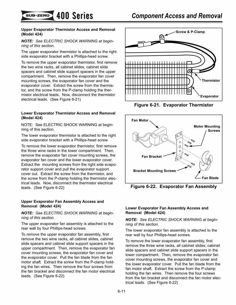
400 Series400 Series Component Access and Removal
6-11
Upper Evaporator Thermistor Access and Removal(Model 424)
NOTE: See ELECTRIC SHOCK WARNING at begin-ning of this section.The upper evaporator thermistor is attached to the rightside evaporator bracket with a Phillips-head screw.To remove the upper evaporator thermistor, first removethe two wine racks, all cabinet slides, cabinet slidespacers and cabinet slide support spacers in the uppercompartment. Then, remove the evaporator fan covermounting screws, the evaporator fan cover and theevaporator cover. Extract the screw from the thermis-tor, and the screw from the P-clamp holding the ther-mistor electrical leads. Now, disconnect the thermistorelectrical leads. (See Figure 6-21)
Lower Evaporator Thermistor Access and Removal(Model 424)
NOTE: See ELECTRIC SHOCK WARNING at begin-ning of this section.The lower evaporator thermistor is attached to the rightside evaporator bracket with a Phillips-head screw.To remove the lower evaporator thermistor, first removethe three wine racks in the lower compartment. Then,remove the evaporator fan cover mounting screws, theevaporator fan cover and the lower evaporator cover.Extract the mounting screws from the right side evapo-rator support cover and pull the evaporator supportcover out. Extract the screw from the thermistor, andthe screw from the P-clamp holding the thermistor elec-trical leads. Now, disconnect the thermistor electricalleads. (See Figure 6-22)
Upper Evaporator Fan Assembly Access andRemoval (Model 424)
NOTE: See ELECTRIC SHOCK WARNING at begin-ning of this section.The upper evaporator fan assembly is attached to therear wall by four Phillips-head screws.To remove the upper evaporator fan assembly, firstremove the two wine racks, all cabinet slides, cabinetslide spacers and cabinet slide support spacers in theupper compartment. Then, remove the evaporator fancover mounting screws, the evaporator fan cover andthe evaporator cover. Pull the fan blade from the fanmotor shaft. Extract the screw from the P-clamp hold-ing the fan wires. Then remove the four screws fromthe fan bracket and disconnect the fan motor electricalleads. (See Figure 6-22)
Figure 6-21. Evaporator Thermistor
Figure 6-22. Evaporator Fan Assembly
Lower Evaporator Fan Assembly Access andRemoval (Model 424)
NOTE: See ELECTRIC SHOCK WARNING at begin-ning of this section.The lower evaporator fan assembly is attached to therear wall by four Phillips-head screws.To remove the lower evaporator fan assembly, firstremove the three wine racks, all cabinet slides, cabinetslide spacers and cabinet slide support spacers in thelower compartment. Then, remove the evaporator fancover mounting screws, the evaporator fan cover andthe lower evaporator cover. Pull the fan blade from thefan motor shaft. Extract the screw from the P-clampholding the fan wires. Then remove the four screwsfrom the fan bracket and disconnect the fan motor elec-trical leads. (See Figure 6-22)
Thermistor
Screw & P-Clamp
Evaporator
Fan Motor
Fan Bracket
Motor MountingScrews
Bracket Mounting Screws
Fan Blade
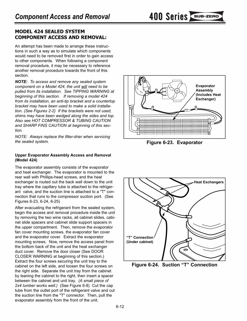
400 Series400 SeriesComponent Access and Removal
6-12
Figure 6-23. Evaporator
Figure 6-24. Suction “T” Connection
Heat Exchangers
“T” Connection(Under cabinet)
MODEL 424 SEALED SYSTEMCOMPONENT ACCESS AND REMOVAL:
An attempt has been made to arrange these instruc-tions in such a way as to simulate which componentswould need to be removed first in order to gain accessto other components. When following a componentremoval procedure, it may be necessary to referenceanother removal procedure towards the front of thissection.NOTE: To access and remove any sealed systemcomponent on a Model 424, the unit will need to bepulled from its installation. See TIPPING WARNING atbeginning of this section. If removing a model 424from its installation, an anti-tip bracket and a countertopbracket may have been used to make a solid installa-tion. (See Figures 2-2) If the brackets were not used,shims may have been wedged along the sides and top.Also see HOT COMPRESSOR & TUBING CAUTIONand SHARP FINS CAUTION at beginning of this sec-tion. NOTE: Always replace the filter-drier when servicingthe sealed system.
Upper Evaporator Assembly Access and Removal(Model 424)
The evaporator assembly consists of the evaporatorand heat exchanger. The evaporator is mounted to therear wall with Phillips-head screws, and the heatexchanger is routed out the back wall down to the unittray where the capillary tube is attached to the refriger-ant valve, and the suction line is attached to a "T" con-nection that runs to the compressor suction port. (SeeFigures 6-23, 6-24, 6-25)After evacuating the refrigerant from the sealed system,begin the access and removal procedure inside the unitby removing the two wine racks, all cabinet slides, cabi-net slide spacers and cabinet slide support spacers inthe upper compartment. Then, remove the evaporatorfan cover mounting screws, the evaporator fan coverand the evaporator cover. Extract the evaporatormounting screws. Now, remove the access panel fromthe bottom back of the unit and the heat exchangerduct cover. Remove the door closer (See DOORCLOSER WARNING at beginning of this section.)Extract the four screws securing the unit tray to thecabinet on the left side, and loosen the four screws onthe right side. Separate the unit tray from the cabinetby leaning the cabinet to the right, then insert a spacerbetween the cabinet and unit tray. (A small piece of2x4 lumber works well.) (See Figure 6-8) Cut the captube from the outlet port of the refrigerant valve and cutthe suction line from the "T" connector. Then, pull theevaporator assembly from the front of the unit.
EvaporatorAssembly(Includes HeatExchanger)
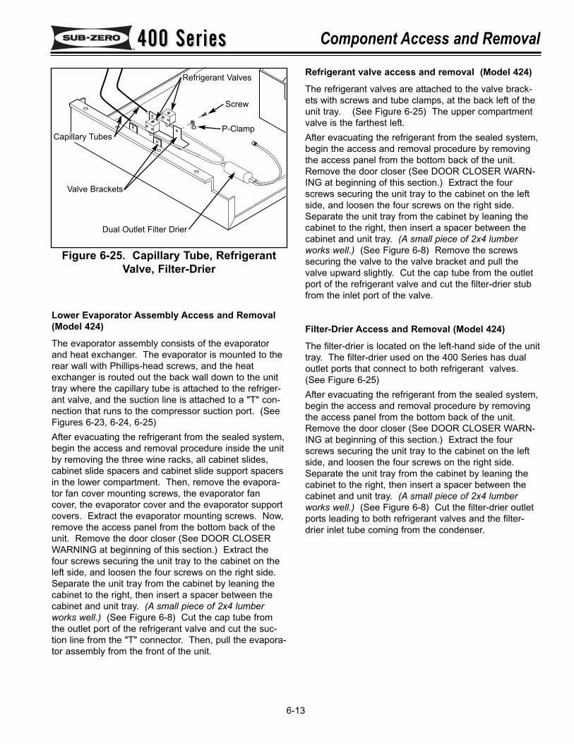
400 Series400 Series Component Access and Removal
6-13
Figure 6-25. Capillary Tube, RefrigerantValve, Filter-Drier
Dual Outlet Filter Drier
Refrigerant Valves
Capillary Tubes
Valve Brackets
P-Clamp
Screw
Lower Evaporator Assembly Access and Removal(Model 424)
The evaporator assembly consists of the evaporatorand heat exchanger. The evaporator is mounted to therear wall with Phillips-head screws, and the heatexchanger is routed out the back wall down to the unittray where the capillary tube is attached to the refriger-ant valve, and the suction line is attached to a "T" con-nection that runs to the compressor suction port. (SeeFigures 6-23, 6-24, 6-25)After evacuating the refrigerant from the sealed system,begin the access and removal procedure inside the unitby removing the three wine racks, all cabinet slides,cabinet slide spacers and cabinet slide support spacersin the lower compartment. Then, remove the evapora-tor fan cover mounting screws, the evaporator fancover, the evaporator cover and the evaporator supportcovers. Extract the evaporator mounting screws. Now,remove the access panel from the bottom back of theunit. Remove the door closer (See DOOR CLOSERWARNING at beginning of this section.) Extract thefour screws securing the unit tray to the cabinet on theleft side, and loosen the four screws on the right side.Separate the unit tray from the cabinet by leaning thecabinet to the right, then insert a spacer between thecabinet and unit tray. (A small piece of 2x4 lumberworks well.) (See Figure 6-8) Cut the cap tube fromthe outlet port of the refrigerant valve and cut the suc-tion line from the "T" connector. Then, pull the evapora-tor assembly from the front of the unit.
Refrigerant valve access and removal (Model 424)
The refrigerant valves are attached to the valve brack-ets with screws and tube clamps, at the back left of theunit tray. (See Figure 6-25) The upper compartmentvalve is the farthest left.After evacuating the refrigerant from the sealed system,begin the access and removal procedure by removingthe access panel from the bottom back of the unit.Remove the door closer (See DOOR CLOSER WARN-ING at beginning of this section.) Extract the fourscrews securing the unit tray to the cabinet on the leftside, and loosen the four screws on the right side.Separate the unit tray from the cabinet by leaning thecabinet to the right, then insert a spacer between thecabinet and unit tray. (A small piece of 2x4 lumberworks well.) (See Figure 6-8) Remove the screwssecuring the valve to the valve bracket and pull thevalve upward slightly. Cut the cap tube from the outletport of the refrigerant valve and cut the filter-drier stubfrom the inlet port of the valve.
Filter-Drier Access and Removal (Model 424)
The filter-drier is located on the left-hand side of the unittray. The filter-drier used on the 400 Series has dualoutlet ports that connect to both refrigerant valves.(See Figure 6-25)After evacuating the refrigerant from the sealed system,begin the access and removal procedure by removingthe access panel from the bottom back of the unit.Remove the door closer (See DOOR CLOSER WARN-ING at beginning of this section.) Extract the fourscrews securing the unit tray to the cabinet on the leftside, and loosen the four screws on the right side.Separate the unit tray from the cabinet by leaning thecabinet to the right, then insert a spacer between thecabinet and unit tray. (A small piece of 2x4 lumberworks well.) (See Figure 6-8) Cut the filter-drier outletports leading to both refrigerant valves and the filter-drier inlet tube coming from the condenser.
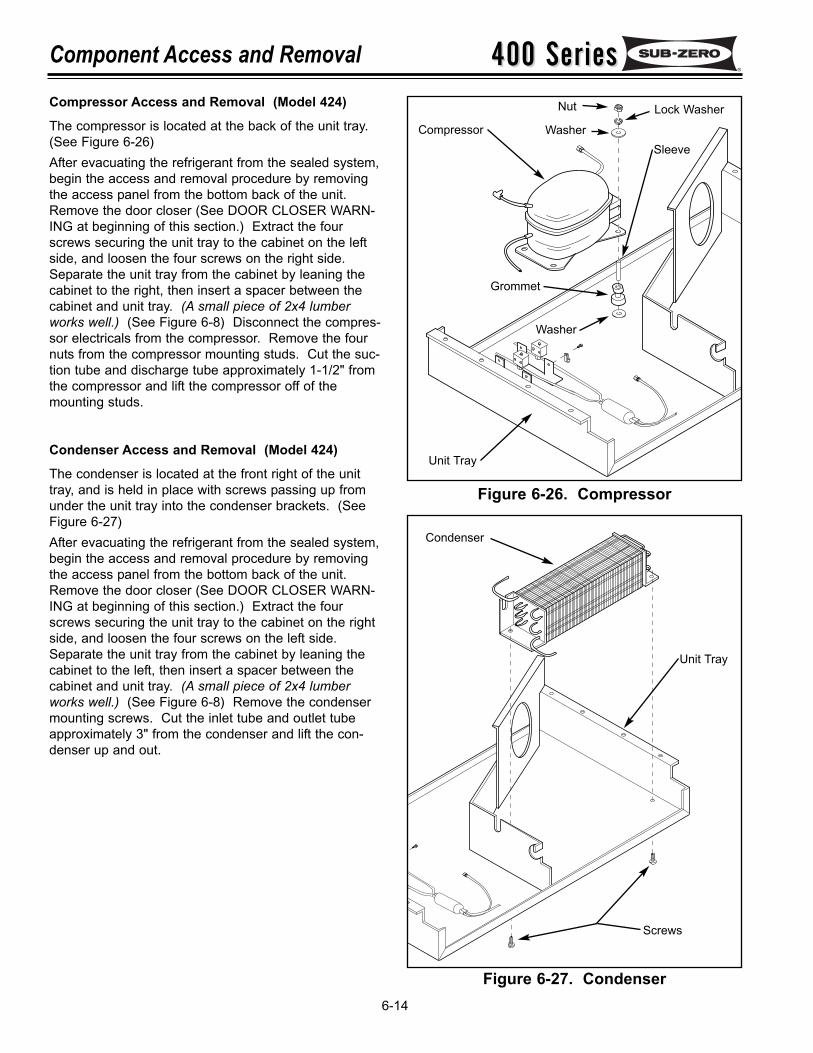
400 Series400 SeriesComponent Access and Removal
6-14
Compressor Access and Removal (Model 424)
The compressor is located at the back of the unit tray.(See Figure 6-26)After evacuating the refrigerant from the sealed system,begin the access and removal procedure by removingthe access panel from the bottom back of the unit.Remove the door closer (See DOOR CLOSER WARN-ING at beginning of this section.) Extract the fourscrews securing the unit tray to the cabinet on the leftside, and loosen the four screws on the right side.Separate the unit tray from the cabinet by leaning thecabinet to the right, then insert a spacer between thecabinet and unit tray. (A small piece of 2x4 lumberworks well.) (See Figure 6-8) Disconnect the compres-sor electricals from the compressor. Remove the fournuts from the compressor mounting studs. Cut the suc-tion tube and discharge tube approximately 1-1/2" fromthe compressor and lift the compressor off of themounting studs.
Condenser Access and Removal (Model 424)
The condenser is located at the front right of the unittray, and is held in place with screws passing up fromunder the unit tray into the condenser brackets. (SeeFigure 6-27)After evacuating the refrigerant from the sealed system,begin the access and removal procedure by removingthe access panel from the bottom back of the unit.Remove the door closer (See DOOR CLOSER WARN-ING at beginning of this section.) Extract the fourscrews securing the unit tray to the cabinet on the rightside, and loosen the four screws on the left side.Separate the unit tray from the cabinet by leaning thecabinet to the left, then insert a spacer between thecabinet and unit tray. (A small piece of 2x4 lumberworks well.) (See Figure 6-8) Remove the condensermounting screws. Cut the inlet tube and outlet tubeapproximately 3" from the condenser and lift the con-denser up and out.
Figure 6-26. Compressor
Figure 6-27. Condenser
Compressor
Unit Tray
Condenser
Screws
Unit Tray
Nut Lock Washer
WasherSleeve
Grommet
Washer
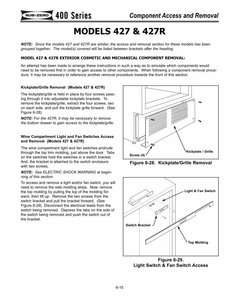
400 Series400 Series Component Access and Removal
6-15
MODELS 427 & 427RNOTE: Since the models 427 and 427R are similar, the access and removal section for these models has beengrouped together. The model(s) covered will be listed between brackets after the heading.
MODEL 427 & 427R EXTERIOR COSMETIC AND MECHANICAL COMPONENT REMOVAL:
An attempt has been made to arrange these instructions in such a way as to simulate which components wouldneed to be removed first in order to gain access to other components. When following a component removal proce-dure, it may be necessary to reference another removal procedure towards the front of this section.
Figure 6-28. Kickplate/Grille Removal
Figure 6-29.Light Switch & Fan Switch Access
Kickplate / GrilleScrew (4)
Light & Fan Switch
Top Molding
Switch Bracket
Kickplate/Grille Removal (Models 427 & 427R)
The kickplate/grille is held in place by four screws pass-ing through it into adjustable kickplate brackets. Toremove the kickplate/grille, extract the four screws, twoon each side, and pull the kickplate grille forward. (SeeFigure 6-28)NOTE: For the 427R, it may be necessary to removethe bottom drawer to gain access to the kickplate/grille.
Wine Compartment Light and Fan Switches Accessand Removal (Models 427 & 427R)
The wine compartment light and fan switches protrudethrough the top trim molding, just above the door. Tabson the switches hold the switches in a switch bracket.And, the bracket is attached to the switch enclosurewith two screws. NOTE: See ELECTRIC SHOCK WARNING at begin-ning of this section.To access and remove a light and/or fan switch, you willneed to remove the side molding strips. Now, removethe top molding by pulling the top of the molding for-ward, then lift up. Remove the two screws from theswitch bracket and pull the bracket forward. (SeeFigure 6-29) Disconnect the electrical leads from theswitch being removed. Depress the tabs on the side ofthe switch being removed and push the switch out ofthe bracket.
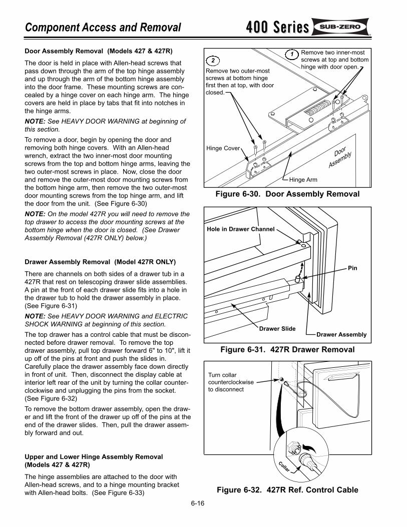
Hinge Cover
Remove two inner-mostscrews at top and bottomhinge with door open.Remove two outer-most
screws at bottom hingefirst then at top, with doorclosed.
Door
Assembly
Hinge Arm
400 Series400 SeriesComponent Access and Removal
6-16
Figure 6-30. Door Assembly Removal
Figure 6-32. 427R Ref. Control Cable
Figure 6-31. 427R Drawer Removal
Pin
Drawer Slide
Hole in Drawer Channel
Drawer Assembly
Turn collarcounterclockwiseto disconnect
Collar
12
Door Assembly Removal (Models 427 & 427R)
The door is held in place with Allen-head screws thatpass down through the arm of the top hinge assemblyand up through the arm of the bottom hinge assemblyinto the door frame. These mounting screws are con-cealed by a hinge cover on each hinge arm. The hingecovers are held in place by tabs that fit into notches inthe hinge arms.NOTE: See HEAVY DOOR WARNING at beginning ofthis section.To remove a door, begin by opening the door andremoving both hinge covers. With an Allen-headwrench, extract the two inner-most door mountingscrews from the top and bottom hinge arms, leaving thetwo outer-most screws in place. Now, close the doorand remove the outer-most door mounting screws fromthe bottom hinge arm, then remove the two outer-mostdoor mounting screws from the top hinge arm, and liftthe door from the unit. (See Figure 6-30)NOTE: On the model 427R you will need to remove thetop drawer to access the door mounting screws at thebottom hinge when the door is closed. (See DrawerAssembly Removal (427R ONLY) below.)
Drawer Assembly Removal (Model 427R ONLY)
There are channels on both sides of a drawer tub in a427R that rest on telescoping drawer slide assemblies.A pin at the front of each drawer slide fits into a hole inthe drawer tub to hold the drawer assembly in place.(See Figure 6-31)NOTE: See HEAVY DOOR WARNING and ELECTRICSHOCK WARNING at beginning of this section.The top drawer has a control cable that must be discon-nected before drawer removal. To remove the topdrawer assembly, pull top drawer forward 6" to 10", lift itup off of the pins at front and push the slides in.Carefully place the drawer assembly face down directlyin front of unit. Then, disconnect the display cable atinterior left rear of the unit by turning the collar counter-clockwise and unplugging the pins from the socket.(See Figure 6-32)To remove the bottom drawer assembly, open the draw-er and lift the front of the drawer up off of the pins at theend of the drawer slides. Then, pull the drawer assem-bly forward and out.
Upper and Lower Hinge Assembly Removal(Models 427 & 427R)
The hinge assemblies are attached to the door withAllen-head screws, and to a hinge mounting bracketwith Allen-head bolts. (See Figure 6-33)
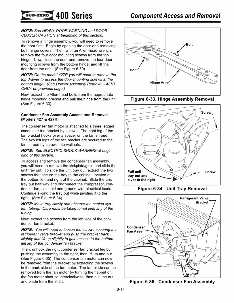
400 Series400 Series Component Access and Removal
6-17
Figure 6-33. Hinge Assembly Removal
Figure 6-34. Unit Tray Removal
Figure 6-35. Condenser Fan Assembly
Hinge Arm
Bolt
Bolt
Pull unit tray out andpivot to the right
Screw
CondenserFan Assy
Refrigerant ValveBracket
Screw
NOTE: See HEAVY DOOR WARNING and DOORCLOSER CAUTION at beginning of this section.To remove a hinge assembly, you will need to removethe door first. Begin by opening the door and removingboth hinge covers. Then, with an Allen-head wrench,remove the four door mounting screws from the tophinge. Now, close the door and remove the four doormounting screws from the bottom hinge, and lift thedoor from the unit. (See Figure 6-30)NOTE: On the model 427R you will need to remove thetop drawer to access the door mounting screws at thebottom hinge. (See Drawer Assembly Removal - 427RONLY, on previous page.)Now, extract the Allen-head bolts from the appropriatehinge mounting bracket and pull the hinge from the unit.(See Figure 6-33)
Condenser Fan Assembly Access and Removal(Models 427 & 427R)
The condenser fan motor is attached to a three leggedcondenser fan bracket by screws. The right leg of thefan bracket hooks over a spacer on the fan shroud.The two left legs of the fan bracket are secured to thefan shroud by screws into wellnuts.NOTE: See ELECTRIC SHOCK WARNING at begin-ning of this section.To access and remove the condenser fan assembly,you will need to remove the kickplate/grille and slide theunit tray out. To slide the unit tray out, extract the twoscrews that secure the tray to the cabinet, located atthe bottom left and right of the cabinet. Slide the unittray out half way and disconnect the compressor, con-denser fan, solenoid and ground wire electrical leads.Continue sliding the tray out while pivoting it to theright. (See Figure 6-34)NOTE: Move tray slowly and observe the sealed sys-tem tubing. Care must be taken to not kink any of thetubing.Now, extract the screws from the left legs of the con-denser fan bracket. NOTE: You will need to loosen the screws securing therefrigerant valve bracket and push the bracket backslightly and lift up slightly to gain access to the bottomleft leg of the condenser fan bracket.Then, unhook the right condenser fan bracket leg bypushing the assembly to the right, then lift up and out.(See Figure 6-35) The condenser fan motor can nowbe removed from the bracket by extracting the screwsin the back side of the fan motor. The fan blade can beremoved from the fan motor by turning the flat-nut onthe fan motor shaft counterclockwise, then pull the nutand blade from the shaft.
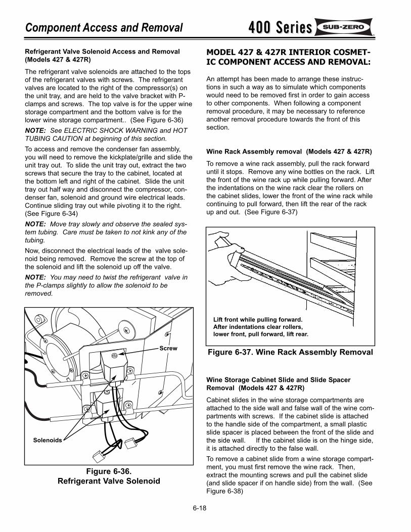
400 Series400 SeriesComponent Access and Removal
6-18
Figure 6-36.Refrigerant Valve Solenoid
Figure 6-37. Wine Rack Assembly Removal
MODEL 427 & 427R INTERIOR COSMET-IC COMPONENT ACCESS AND REMOVAL:
An attempt has been made to arrange these instruc-tions in such a way as to simulate which componentswould need to be removed first in order to gain accessto other components. When following a componentremoval procedure, it may be necessary to referenceanother removal procedure towards the front of thissection.
Wine Rack Assembly removal (Models 427 & 427R)
To remove a wine rack assembly, pull the rack forwarduntil it stops. Remove any wine bottles on the rack. Liftthe front of the wine rack up while pulling forward. Afterthe indentations on the wine rack clear the rollers onthe cabinet slides, lower the front of the wine rack whilecontinuing to pull forward, then lift the rear of the rackup and out. (See Figure 6-37)
Wine Storage Cabinet Slide and Slide SpacerRemoval (Models 427 & 427R)
Cabinet slides in the wine storage compartments areattached to the side wall and false wall of the wine com-partments with screws. If the cabinet slide is attachedto the handle side of the compartment, a small plasticslide spacer is placed between the front of the slide andthe side wall. If the cabinet slide is on the hinge side,it is attached directly to the false wall.To remove a cabinet slide from a wine storage compart-ment, you must first remove the wine rack. Then,extract the mounting screws and pull the cabinet slide(and slide spacer if on handle side) from the wall. (SeeFigure 6-38)
Screw
Solenoids
Lift front while pulling forward.After indentations clear rollers,lower front, pull forward, lift rear.
Refrigerant Valve Solenoid Access and Removal(Models 427 & 427R)
The refrigerant valve solenoids are attached to the topsof the refrigerant valves with screws. The refrigerantvalves are located to the right of the compressor(s) onthe unit tray, and are held to the valve bracket with P-clamps and screws. The top valve is for the upper winestorage compartment and the bottom valve is for thelower wine storage compartment.. (See Figure 6-36)NOTE: See ELECTRIC SHOCK WARNING and HOTTUBING CAUTION at beginning of this section.To access and remove the condenser fan assembly,you will need to remove the kickplate/grille and slide theunit tray out. To slide the unit tray out, extract the twoscrews that secure the tray to the cabinet, located atthe bottom left and right of the cabinet. Slide the unittray out half way and disconnect the compressor, con-denser fan, solenoid and ground wire electrical leads.Continue sliding tray out while pivoting it to the right.(See Figure 6-34)NOTE: Move tray slowly and observe the sealed sys-tem tubing. Care must be taken to not kink any of thetubing.Now, disconnect the electrical leads of the valve sole-noid being removed. Remove the screw at the top ofthe solenoid and lift the solenoid up off the valve.NOTE: You may need to twist the refrigerant valve inthe P-clamps slightly to allow the solenoid to beremoved.
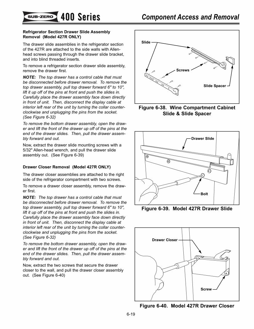
400 Series400 Series Component Access and Removal
6-19
Figure 6-38. Wine Compartment CabinetSlide & Slide Spacer
Figure 6-39. Model 427R Drawer Slide
Refrigerator Section Drawer Slide AssemblyRemoval (Model 427R ONLY)
The drawer slide assemblies in the refrigerator sectionof the 427R are attached to the side walls with Allen-head screws passing through the drawer slide bracket,and into blind threaded inserts.To remove a refrigerator section drawer slide assembly,remove the drawer first.NOTE: The top drawer has a control cable that mustbe disconnected before drawer removal. To remove thetop drawer assembly, pull top drawer forward 6" to 10",lift it up off of the pins at front and push the slides in.Carefully place the drawer assembly face down directlyin front of unit. Then, disconnect the display cable atinterior left rear of the unit by turning the collar counter-clockwise and unplugging the pins from the socket.(See Figure 6-32)To remove the bottom drawer assembly, open the draw-er and lift the front of the drawer up off of the pins at theend of the drawer slides. Then, pull the drawer assem-bly forward and out.Now, extract the drawer slide mounting screws with a5/32" Allen-head wrench, and pull the drawer slideassembly out. (See Figure 6-39)
Drawer Closer Removal (Model 427R ONLY)
The drawer closer assemblies are attached to the rightside of the refrigerator compartment with two screws.To remove a drawer closer assembly, remove the draw-er first.NOTE: The top drawer has a control cable that mustbe disconnected before drawer removal. To remove thetop drawer assembly, pull top drawer forward 6" to 10",lift it up off of the pins at front and push the slides in.Carefully place the drawer assembly face down directlyin front of unit. Then, disconnect the display cable atinterior left rear of the unit by turning the collar counter-clockwise and unplugging the pins from the socket.(See Figure 6-32)To remove the bottom drawer assembly, open the draw-er and lift the front of the drawer up off of the pins at theend of the drawer slides. Then, pull the drawer assem-bly forward and out.Now, extract the two screws that secure the drawercloser to the wall, and pull the drawer closer assemblyout. (See Figure 6-40)
Slide
Screws
Slide Spacer
Figure 6-40. Model 427R Drawer Closer
Drawer Slide
Bolt
Drawer Closer
Screw
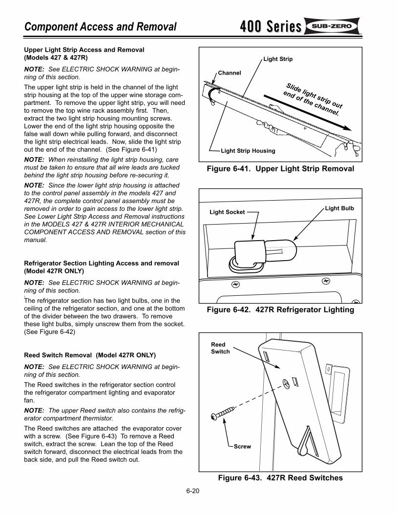
400 Series400 SeriesComponent Access and Removal
6-20
Figure 6-41. Upper Light Strip Removal
Upper Light Strip Access and Removal (Models 427 & 427R)
NOTE: See ELECTRIC SHOCK WARNING at begin-ning of this section.The upper light strip is held in the channel of the lightstrip housing at the top of the upper wine storage com-partment. To remove the upper light strip, you will needto remove the top wine rack assembly first. Then,extract the two light strip housing mounting screws.Lower the end of the light strip housing opposite thefalse wall down while pulling forward, and disconnectthe light strip electrical leads. Now, slide the light stripout the end of the channel. (See Figure 6-41)NOTE: When reinstalling the light strip housing, caremust be taken to ensure that all wire leads are tuckedbehind the light strip housing before re-securing it.NOTE: Since the lower light strip housing is attachedto the control panel assembly in the models 427 and427R, the complete control panel assembly must beremoved in order to gain access to the lower light strip.See Lower Light Strip Access and Removal instructionsin the MODELS 427 & 427R INTERIOR MECHANICALCOMPONENT ACCESS AND REMOVAL section of thismanual.
Refrigerator Section Lighting Access and removal(Model 427R ONLY)
NOTE: See ELECTRIC SHOCK WARNING at begin-ning of this section.3
The refrigerator section has two light bulbs, one in theceiling of the refrigerator section, and one at the bottomof the divider between the two drawers. To removethese light bulbs, simply unscrew them from the socket.(See Figure 6-42)
Reed Switch Removal (Model 427R ONLY)
NOTE: See ELECTRIC SHOCK WARNING at begin-ning of this section.The Reed switches in the refrigerator section controlthe refrigerator compartment lighting and evaporatorfan.NOTE: The upper Reed switch also contains the refrig-erator compartment thermistor.The Reed switches are attached the evaporator coverwith a screw. (See Figure 6-43) To remove a Reedswitch, extract the screw. Lean the top of the Reedswitch forward, disconnect the electrical leads from theback side, and pull the Reed switch out.
Figure 6-42. 427R Refrigerator Lighting
Figure 6-43. 427R Reed Switches
Slide light strip out
end of the channel.
Channel
Light Strip
Light Strip Housing
ReedSwitch
Screw
Light BulbLight Socket
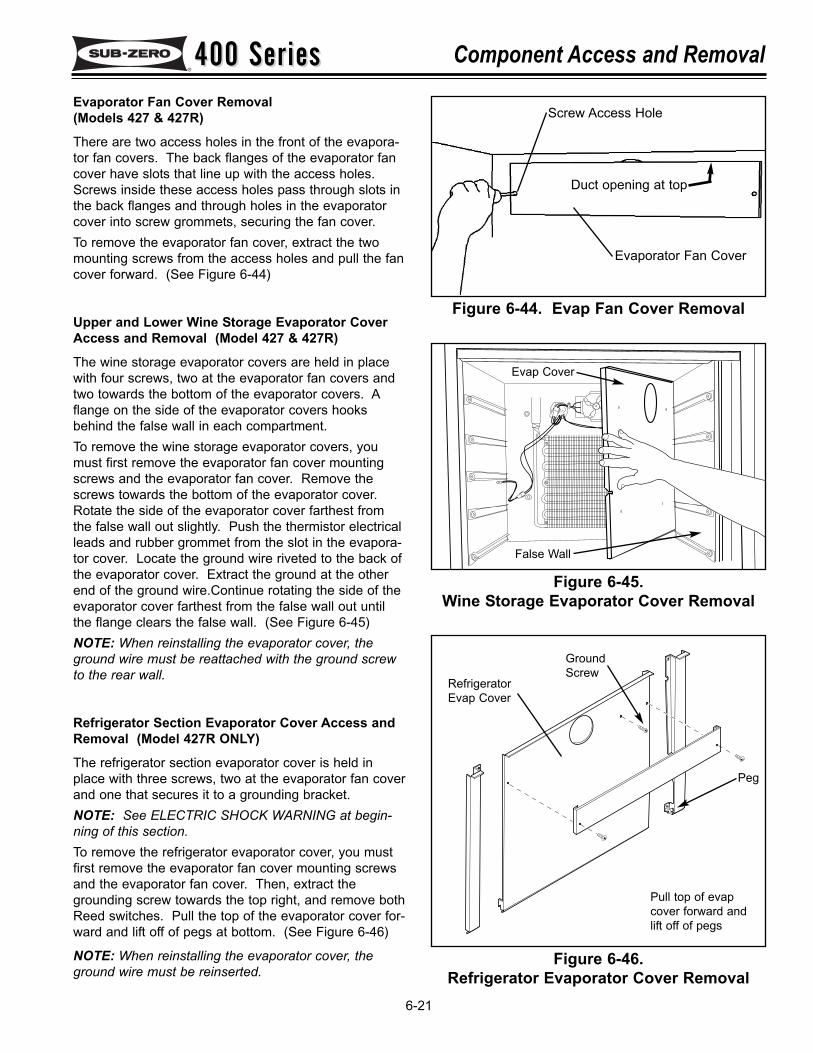
400 Series400 Series Component Access and Removal
6-21
Figure 6-44. Evap Fan Cover Removal
Duct opening at top
Evaporator Fan Cover
Screw Access HoleEvaporator Fan Cover Removal(Models 427 & 427R)
There are two access holes in the front of the evapora-tor fan covers. The back flanges of the evaporator fancover have slots that line up with the access holes.Screws inside these access holes pass through slots inthe back flanges and through holes in the evaporatorcover into screw grommets, securing the fan cover.To remove the evaporator fan cover, extract the twomounting screws from the access holes and pull the fancover forward. (See Figure 6-44)
Upper and Lower Wine Storage Evaporator CoverAccess and Removal (Model 427 & 427R)
The wine storage evaporator covers are held in placewith four screws, two at the evaporator fan covers andtwo towards the bottom of the evaporator covers. Aflange on the side of the evaporator covers hooksbehind the false wall in each compartment.To remove the wine storage evaporator covers, youmust first remove the evaporator fan cover mountingscrews and the evaporator fan cover. Remove thescrews towards the bottom of the evaporator cover.Rotate the side of the evaporator cover farthest fromthe false wall out slightly. Push the thermistor electricalleads and rubber grommet from the slot in the evapora-tor cover. Locate the ground wire riveted to the back ofthe evaporator cover. Extract the ground at the otherend of the ground wire.Continue rotating the side of theevaporator cover farthest from the false wall out untilthe flange clears the false wall. (See Figure 6-45)NOTE: When reinstalling the evaporator cover, theground wire must be reattached with the ground screwto the rear wall.
Refrigerator Section Evaporator Cover Access andRemoval (Model 427R ONLY)
The refrigerator section evaporator cover is held inplace with three screws, two at the evaporator fan coverand one that secures it to a grounding bracket. NOTE: See ELECTRIC SHOCK WARNING at begin-ning of this section.To remove the refrigerator evaporator cover, you mustfirst remove the evaporator fan cover mounting screwsand the evaporator fan cover. Then, extract thegrounding screw towards the top right, and remove bothReed switches. Pull the top of the evaporator cover for-ward and lift off of pegs at bottom. (See Figure 6-46)
NOTE: When reinstalling the evaporator cover, theground wire must be reinserted.
Figure 6-45.Wine Storage Evaporator Cover Removal
Figure 6-46.Refrigerator Evaporator Cover Removal
Pull top of evapcover forward andlift off of pegs
RefrigeratorEvap Cover
Peg
GroundScrew
False Wall
Evap Cover
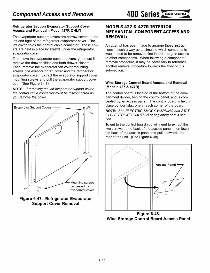
400 Series400 SeriesComponent Access and Removal
6-22
MODELS 427 & 427R INTERIORMECHANICAL COMPONENT ACCESS ANDREMOVAL:
An attempt has been made to arrange these instruc-tions in such a way as to simulate which componentswould need to be removed first in order to gain accessto other components. When following a componentremoval procedure, it may be necessary to referenceanother removal procedure towards the front of thissub-section.
Wine Storage Control Board Access and Removal(Models 427 & 427R)
The control board is located at the bottom of the com-partment divider, behind the control panel, and is con-cealed by an access panel. The control board is held inplace by four tabs, one at each corner of the board.NOTE: See ELECTRIC SHOCK WARNING and STAT-IC ELECTRICITY CAUTION at beginning of this sec-tion.To get to the control board you will need to extract thetwo screws at the back of the access panel, then lowerthe back of the access panel and pull it towards therear of the unit. (See Figure 6-48)
Figure 6-48.Wine Storage Control Board Access Panel
Refrigerator Section Evaporator Support CoverAccess and Removal (Model 427R ONLY)
The evaporator support covers are narrow covers to theleft and right of the refrigerator evaporator cover. Theleft cover holds the control cable connector. These cov-ers are held in place by screws under the refrigeratorevaporator cover.To remove the evaporator support covers, you must firstremove the drawer slides and both drawer closers.Then, remove the evaporator fan cover mountingscrews, the evaporator fan cover and the refrigeratorevaporator cover. Extract the evaporator support covermounting screws and pull the evaporator support coverout. (See Figure 6-47)NOTE: If removing the left evaporator support cover,the control cable connector must be disconnected asyou remove the cover.
Figure 6-47. Refrigerator EvaporatorSupport Cover Removal
Evaporator Support Covers
Mounting screws concealed by evaporator cover
Access Panel
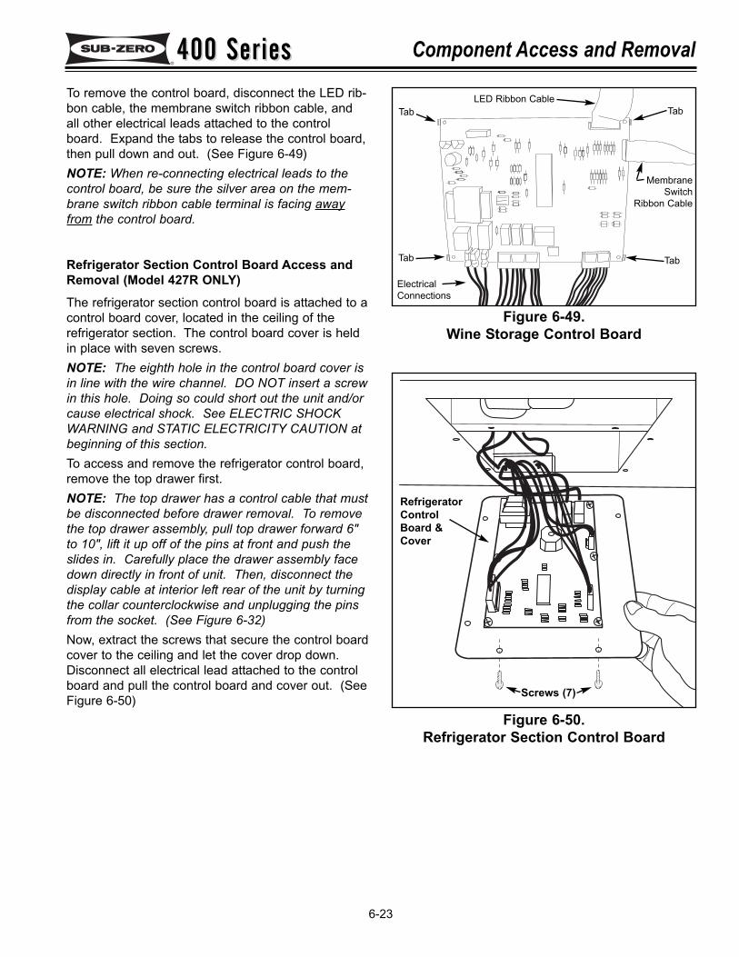
400 Series400 Series Component Access and Removal
6-23
Figure 6-49.Wine Storage Control Board
Tab
LED Ribbon Cable
MembraneSwitch
Ribbon Cable
ElectricalConnections
Tab
TabTab
To remove the control board, disconnect the LED rib-bon cable, the membrane switch ribbon cable, andall other electrical leads attached to the controlboard. Expand the tabs to release the control board,then pull down and out. (See Figure 6-49)NOTE: When re-connecting electrical leads to thecontrol board, be sure the silver area on the mem-brane switch ribbon cable terminal is facing awayfrom the control board.
Refrigerator Section Control Board Access andRemoval (Model 427R ONLY)The refrigerator section control board is attached to acontrol board cover, located in the ceiling of therefrigerator section. The control board cover is heldin place with seven screws.NOTE: The eighth hole in the control board cover isin line with the wire channel. DO NOT insert a screwin this hole. Doing so could short out the unit and/orcause electrical shock. See ELECTRIC SHOCKWARNING and STATIC ELECTRICITY CAUTION atbeginning of this section.To access and remove the refrigerator control board,remove the top drawer first.NOTE: The top drawer has a control cable that mustbe disconnected before drawer removal. To removethe top drawer assembly, pull top drawer forward 6"to 10", lift it up off of the pins at front and push theslides in. Carefully place the drawer assembly facedown directly in front of unit. Then, disconnect thedisplay cable at interior left rear of the unit by turningthe collar counterclockwise and unplugging the pinsfrom the socket. (See Figure 6-32)Now, extract the screws that secure the control boardcover to the ceiling and let the cover drop down.Disconnect all electrical lead attached to the controlboard and pull the control board and cover out. (SeeFigure 6-50)
Figure 6-50.Refrigerator Section Control Board
RefrigeratorControlBoard &Cover
Screws (7)
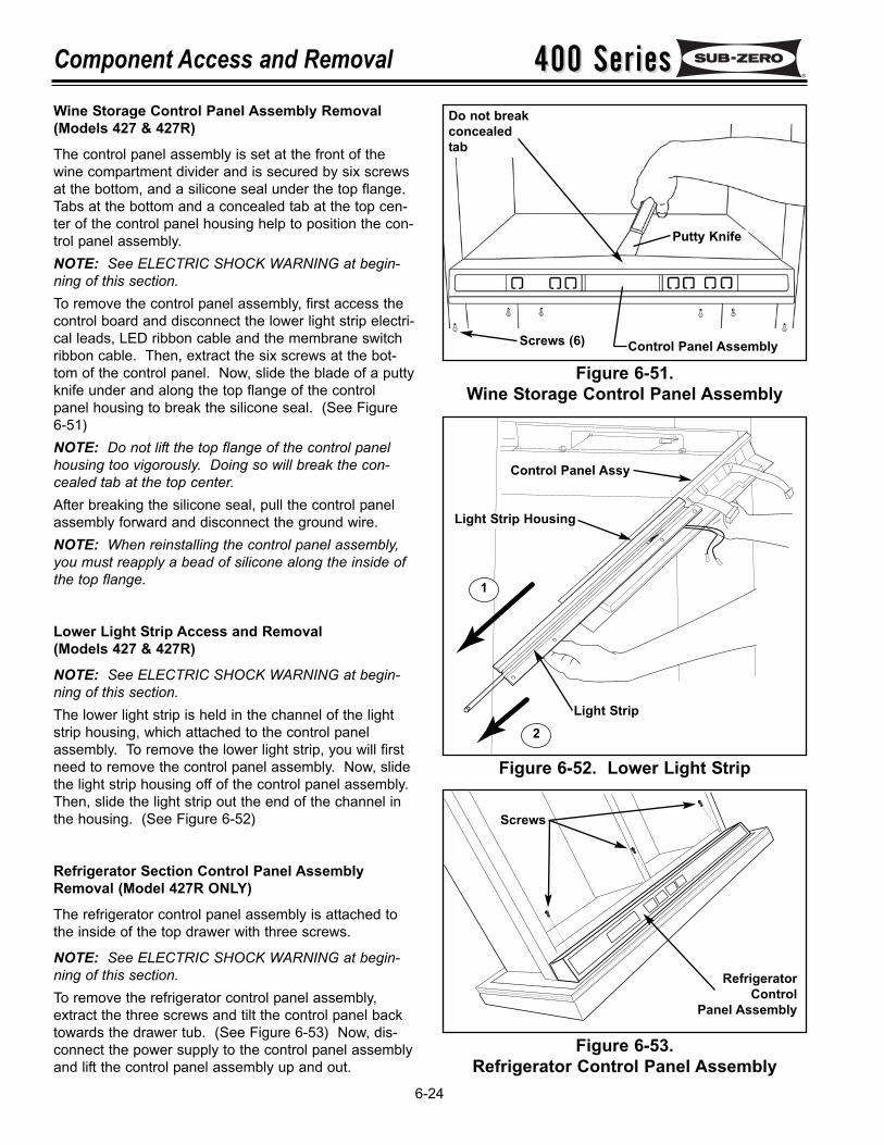
400 Series400 SeriesComponent Access and Removal
6-24
Figure 6-51.Wine Storage Control Panel Assembly
Figure 6-53.Refrigerator Control Panel Assembly
Wine Storage Control Panel Assembly Removal(Models 427 & 427R)
The control panel assembly is set at the front of thewine compartment divider and is secured by six screwsat the bottom, and a silicone seal under the top flange.Tabs at the bottom and a concealed tab at the top cen-ter of the control panel housing help to position the con-trol panel assembly.NOTE: See ELECTRIC SHOCK WARNING at begin-ning of this section.To remove the control panel assembly, first access thecontrol board and disconnect the lower light strip electri-cal leads, LED ribbon cable and the membrane switchribbon cable. Then, extract the six screws at the bot-tom of the control panel. Now, slide the blade of a puttyknife under and along the top flange of the controlpanel housing to break the silicone seal. (See Figure6-51)NOTE: Do not lift the top flange of the control panelhousing too vigorously. Doing so will break the con-cealed tab at the top center.After breaking the silicone seal, pull the control panelassembly forward and disconnect the ground wire.NOTE: When reinstalling the control panel assembly,you must reapply a bead of silicone along the inside ofthe top flange.
Lower Light Strip Access and Removal (Models 427 & 427R)
NOTE: See ELECTRIC SHOCK WARNING at begin-ning of this section.The lower light strip is held in the channel of the lightstrip housing, which attached to the control panelassembly. To remove the lower light strip, you will firstneed to remove the control panel assembly. Now, slidethe light strip housing off of the control panel assembly.Then, slide the light strip out the end of the channel inthe housing. (See Figure 6-52)
Refrigerator Section Control Panel AssemblyRemoval (Model 427R ONLY)
The refrigerator control panel assembly is attached tothe inside of the top drawer with three screws.
NOTE: See ELECTRIC SHOCK WARNING at begin-ning of this section.To remove the refrigerator control panel assembly,extract the three screws and tilt the control panel backtowards the drawer tub. (See Figure 6-53) Now, dis-connect the power supply to the control panel assemblyand lift the control panel assembly up and out.
Control Panel Assembly
Putty Knife
Screws (6)
Do not breakconcealedtab
1
2
Control Panel Assy
Light Strip Housing
Light Strip
Figure 6-52. Lower Light Strip
RefrigeratorControl
Panel Assembly
Screws

400 Series400 Series Component Access and Removal
6-25
Figure 6-54.Wine Storage Compartment Thermistors
Figure 6-55.Wine Storage Evaporator Thermistors
Wine Storage Compartment Thermistors Accessand Removal (Models 427 & 427R)
The upper and lower wine compartment thermistors areattached to the wall of both compartments with Phillips-head screws, and the electrical leads of the thermistorsare routed through notches in the side of the evaporatorcovers and guarded by a wire grommets. (See Figure6-54)NOTE: See ELECTRIC SHOCK WARNING at begin-ning of this section.To remove a compartment thermistor, you must firstremove the wine racks in the appropriate compartment.Then, remove the screw from the compartment thermis-tor. Remove the evaporator fan cover mounting screwsand the evaporator fan cover. Remove the mountingscrews towards the bottom of the evaporator cover.Rotate the side of the evaporator cover farthest fromthe false wall out slightly and push the thermistor elec-trical leads and rubber grommet from the slot in theevaporator cover. Now, reach behind the evaporatorcover and disconnect the thermistor electrical leads andremove the thermistor mounting screw. (See Figure 6-54)
Wine Storage Evaporator Thermistors Access andRemoval (Models 427 & 427R)
The upper and lower wine storage evaporator thermis-tors are attached to the right side evaporator bracketsof both evaporators with Phillips-head screws. (SeeFigure 6-55)NOTE: See ELECTRIC SHOCK WARNING at begin-ning of this section.To access and remove a wine storage evaporator ther-mistor, you must first remove the wine racks in theappropriate compartment. Then, remove the evapora-tor fan cover mounting screws and the evaporator fancover. Remove the evaporator cover mounting screwstowards the bottom of the evaporator cover. Rotate theside of the evaporator cover farthest from the false wallout slightly and push the compartment thermistor elec-trical leads and grommet from the slot in the evaporatorcover. You'll find a ground wire riveted to the back ofthe evaporator cover, and the other end of the groundwire has a screw securing it to the rear wall. Extractthe ground screw and continue rotate the side of theevaporator cover farthest from the false wall out untilthe flange clears the false wall. Pull the evaporatorcover out. Remove the screw from the evaporator ther-mistor, disconnect the thermistor electrical leads andpull the evaporator thermistor out. (See Figure 6-55)
Thermistor
Evap Cover
Screw
Slide
Grommet & Slot
Thermistor
P-Clamp
Evaporator
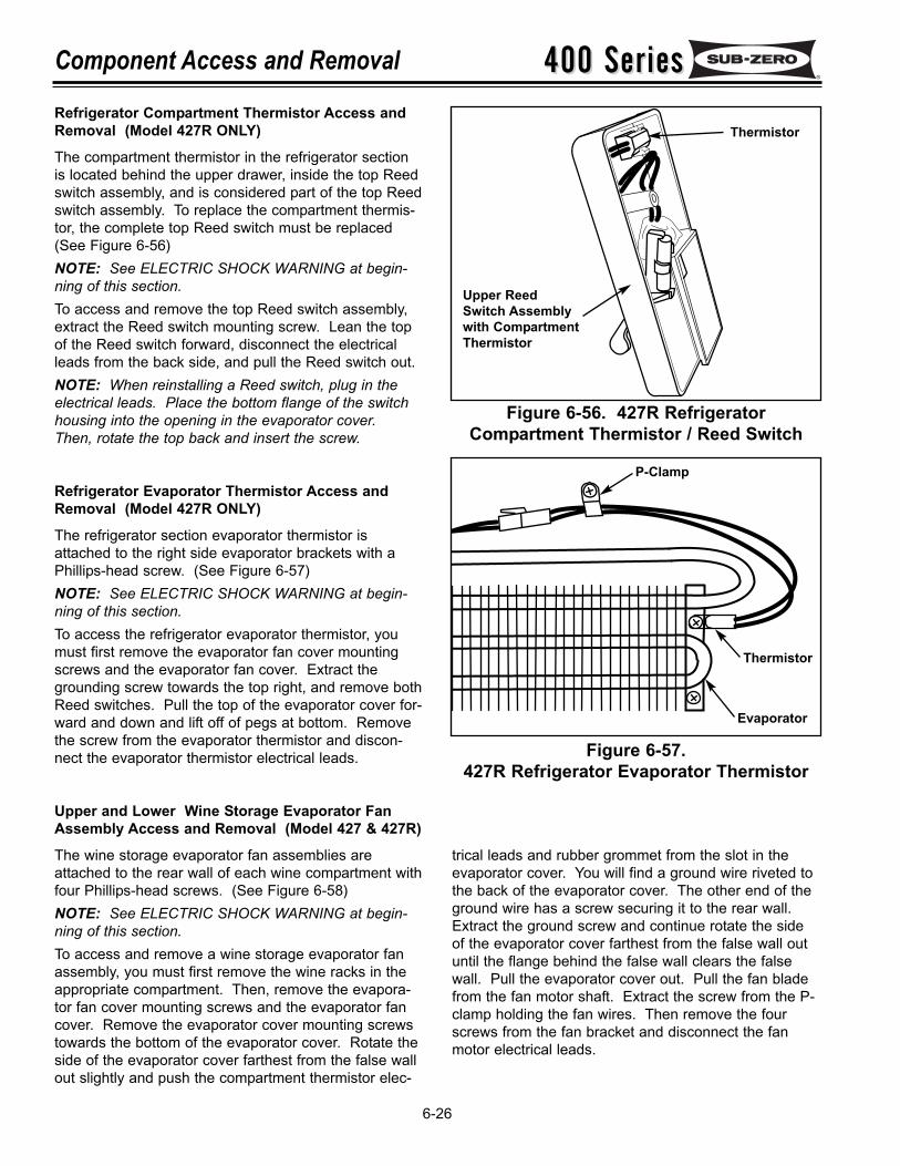
400 Series400 SeriesComponent Access and Removal
6-26
Refrigerator Compartment Thermistor Access andRemoval (Model 427R ONLY)
The compartment thermistor in the refrigerator sectionis located behind the upper drawer, inside the top Reedswitch assembly, and is considered part of the top Reedswitch assembly. To replace the compartment thermis-tor, the complete top Reed switch must be replaced(See Figure 6-56)NOTE: See ELECTRIC SHOCK WARNING at begin-ning of this section.To access and remove the top Reed switch assembly,extract the Reed switch mounting screw. Lean the topof the Reed switch forward, disconnect the electricalleads from the back side, and pull the Reed switch out.NOTE: When reinstalling a Reed switch, plug in theelectrical leads. Place the bottom flange of the switchhousing into the opening in the evaporator cover.Then, rotate the top back and insert the screw.
Refrigerator Evaporator Thermistor Access andRemoval (Model 427R ONLY)
The refrigerator section evaporator thermistor isattached to the right side evaporator brackets with aPhillips-head screw. (See Figure 6-57)NOTE: See ELECTRIC SHOCK WARNING at begin-ning of this section.To access the refrigerator evaporator thermistor, youmust first remove the evaporator fan cover mountingscrews and the evaporator fan cover. Extract thegrounding screw towards the top right, and remove bothReed switches. Pull the top of the evaporator cover for-ward and down and lift off of pegs at bottom. Removethe screw from the evaporator thermistor and discon-nect the evaporator thermistor electrical leads.
Upper and Lower Wine Storage Evaporator FanAssembly Access and Removal (Model 427 & 427R)
The wine storage evaporator fan assemblies areattached to the rear wall of each wine compartment withfour Phillips-head screws. (See Figure 6-58)NOTE: See ELECTRIC SHOCK WARNING at begin-ning of this section.To access and remove a wine storage evaporator fanassembly, you must first remove the wine racks in theappropriate compartment. Then, remove the evapora-tor fan cover mounting screws and the evaporator fancover. Remove the evaporator cover mounting screwstowards the bottom of the evaporator cover. Rotate theside of the evaporator cover farthest from the false wallout slightly and push the compartment thermistor elec-
Figure 6-56. 427R RefrigeratorCompartment Thermistor / Reed Switch
Figure 6-57.427R Refrigerator Evaporator Thermistor
trical leads and rubber grommet from the slot in theevaporator cover. You will find a ground wire riveted tothe back of the evaporator cover. The other end of theground wire has a screw securing it to the rear wall.Extract the ground screw and continue rotate the sideof the evaporator cover farthest from the false wall outuntil the flange behind the false wall clears the falsewall. Pull the evaporator cover out. Pull the fan bladefrom the fan motor shaft. Extract the screw from the P-clamp holding the fan wires. Then remove the fourscrews from the fan bracket and disconnect the fanmotor electrical leads.
Thermistor
P-Clamp
Evaporator
Upper Reed Switch Assemblywith CompartmentThermistor
Thermistor
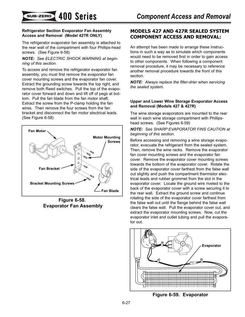
400 Series400 Series Component Access and Removal
6-27
Figure 6-58.Evaporator Fan Assembly
MODELS 427 AND 427R SEALED SYSTEMCOMPONENT ACCESS AND REMOVAL:
An attempt has been made to arrange these instruc-tions in such a way as to simulate which componentswould need to be removed first in order to gain accessto other components. When following a componentremoval procedure, it may be necessary to referenceanother removal procedure towards the front of thissection.NOTE: Always replace the filter-drier when servicingthe sealed system.
Upper and Lower Wine Storage Evaporator Accessand Removal (Models 427 & 427R)
The wine storage evaporators are mounted to the rearwall in each wine storage compartment with Phillips-head screws. (See Figures 6-59)NOTE: See SHARP EVAPORATOR FINS CAUTION atbeginning of this section.Before accessing and removing a wine storage evapo-rator, evacuate the refrigerant from the sealed system.Then, remove the wine racks. Remove the evaporatorfan cover mounting screws and the evaporator fancover. Remove the evaporator cover mounting screwstowards the bottom of the evaporator cover. Rotate theside of the evaporator cover farthest from the false wallout slightly and push the compartment thermistor elec-trical leads and rubber grommet from the slot in theevaporator cover. Locate the ground wire riveted to theback of the evaporator cover with a screw securing it tothe rear wall. Extract the ground screw and continuerotating the side of the evaporator cover farthest fromthe false wall out until the flange behind the false wallclears the false wall. Pull the evaporator cover out, andextract the evaporator mounting screws. Now, cut theevaporator inlet and outlet tubing and pull the evapora-tor out.
Refrigerator Section Evaporator Fan AssemblyAccess and Removal (Model 427R ONLY)
The refrigerator evaporator fan assembly is attached tothe rear wall of the compartment with four Phillips-headscrews. (See Figure 6-58)NOTE: See ELECTRIC SHOCK WARNING at begin-ning of this section.To access and remove the refrigerator evaporator fanassembly, you must first remove the evaporator fancover mounting screws and the evaporator fan cover.Extract the grounding screw towards the top right, andremove both Reed switches. Pull the top of the evapo-rator cover forward and down and lift off of pegs at bot-tom. Pull the fan blade from the fan motor shaft.Extract the screw from the P-clamp holding the fanwires. Then remove the four screws from the fanbracket and disconnect the fan motor electrical leads.(See Figure 6-58)
Fan Motor
Fan Bracket
Motor MountingScrews
Bracket Mounting Screws
Fan Blade
Figure 6-59. Evaporator
Evaporator
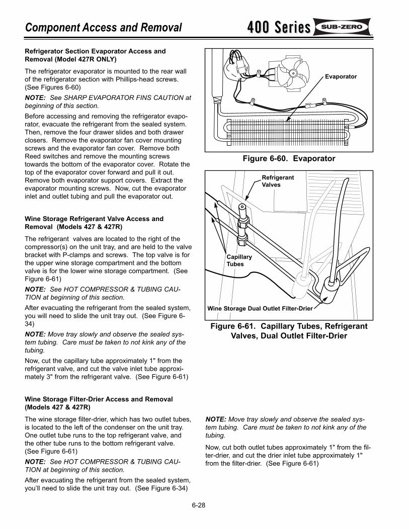
400 Series400 SeriesComponent Access and Removal
6-28
Figure 6-60. Evaporator
Figure 6-61. Capillary Tubes, RefrigerantValves, Dual Outlet Filter-Drier
NOTE: Move tray slowly and observe the sealed sys-tem tubing. Care must be taken to not kink any of thetubing.
Now, cut both outlet tubes approximately 1" from the fil-ter-drier, and cut the drier inlet tube approximately 1"from the filter-drier. (See Figure 6-61)
Evaporator
Refrigerator Section Evaporator Access andRemoval (Model 427R ONLY)
The refrigerator evaporator is mounted to the rear wallof the refrigerator section with Phillips-head screws.(See Figures 6-60)NOTE: See SHARP EVAPORATOR FINS CAUTION atbeginning of this section.Before accessing and removing the refrigerator evapo-rator, evacuate the refrigerant from the sealed system.Then, remove the four drawer slides and both drawerclosers. Remove the evaporator fan cover mountingscrews and the evaporator fan cover. Remove bothReed switches and remove the mounting screwstowards the bottom of the evaporator cover. Rotate thetop of the evaporator cover forward and pull it out.Remove both evaporator support covers. Extract theevaporator mounting screws. Now, cut the evaporatorinlet and outlet tubing and pull the evaporator out.
Wine Storage Refrigerant Valve Access andRemoval (Models 427 & 427R)
The refrigerant valves are located to the right of thecompressor(s) on the unit tray, and are held to the valvebracket with P-clamps and screws. The top valve is forthe upper wine storage compartment and the bottomvalve is for the lower wine storage compartment. (SeeFigure 6-61)NOTE: See HOT COMPRESSOR & TUBING CAU-TION at beginning of this section.After evacuating the refrigerant from the sealed system, you will need to slide the unit tray out. (See Figure 6-34)NOTE: Move tray slowly and observe the sealed sys-tem tubing. Care must be taken to not kink any of thetubing.Now, cut the capillary tube approximately 1" from therefrigerant valve, and cut the valve inlet tube approxi-mately 3" from the refrigerant valve. (See Figure 6-61)
Wine Storage Filter-Drier Access and Removal(Models 427 & 427R)
The wine storage filter-drier, which has two outlet tubes,is located to the left of the condenser on the unit tray.One outlet tube runs to the top refrigerant valve, andthe other tube runs to the bottom refrigerant valve.(See Figure 6-61)NOTE: See HOT COMPRESSOR & TUBING CAU-TION at beginning of this section.After evacuating the refrigerant from the sealed system, you’ll need to slide the unit tray out. (See Figure 6-34)
RefrigerantValves
CapillaryTubes
Wine Storage Dual Outlet Filter-Drier
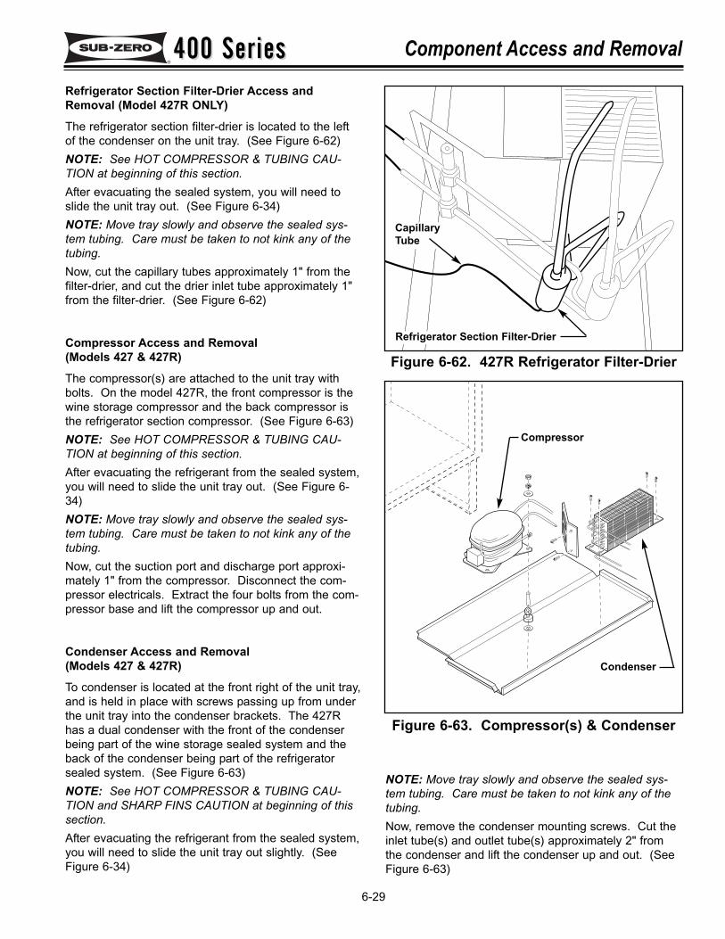
400 Series400 Series Component Access and Removal
6-29
Figure 6-62. 427R Refrigerator Filter-Drier
Figure 6-63. Compressor(s) & Condenser
Refrigerator Section Filter-Drier Access andRemoval (Model 427R ONLY)
The refrigerator section filter-drier is located to the leftof the condenser on the unit tray. (See Figure 6-62)NOTE: See HOT COMPRESSOR & TUBING CAU-TION at beginning of this section.After evacuating the sealed system, you will need toslide the unit tray out. (See Figure 6-34)NOTE: Move tray slowly and observe the sealed sys-tem tubing. Care must be taken to not kink any of thetubing.Now, cut the capillary tubes approximately 1" from thefilter-drier, and cut the drier inlet tube approximately 1"from the filter-drier. (See Figure 6-62)
Compressor Access and Removal(Models 427 & 427R)
The compressor(s) are attached to the unit tray withbolts. On the model 427R, the front compressor is thewine storage compressor and the back compressor isthe refrigerator section compressor. (See Figure 6-63)NOTE: See HOT COMPRESSOR & TUBING CAU-TION at beginning of this section.After evacuating the refrigerant from the sealed system, you will need to slide the unit tray out. (See Figure 6-34)NOTE: Move tray slowly and observe the sealed sys-tem tubing. Care must be taken to not kink any of thetubing.Now, cut the suction port and discharge port approxi-mately 1" from the compressor. Disconnect the com-pressor electricals. Extract the four bolts from the com-pressor base and lift the compressor up and out.
Condenser Access and Removal(Models 427 & 427R)
To condenser is located at the front right of the unit tray,and is held in place with screws passing up from underthe unit tray into the condenser brackets. The 427Rhas a dual condenser with the front of the condenserbeing part of the wine storage sealed system and theback of the condenser being part of the refrigeratorsealed system. (See Figure 6-63)NOTE: See HOT COMPRESSOR & TUBING CAU-TION and SHARP FINS CAUTION at beginning of thissection.After evacuating the refrigerant from the sealed system, you will need to slide the unit tray out slightly. (SeeFigure 6-34)
Refrigerator Section Filter-Drier
CapillaryTube
NOTE: Move tray slowly and observe the sealed sys-tem tubing. Care must be taken to not kink any of thetubing.Now, remove the condenser mounting screws. Cut theinlet tube(s) and outlet tube(s) approximately 2" fromthe condenser and lift the condenser up and out. (SeeFigure 6-63)
Compressor
Condenser
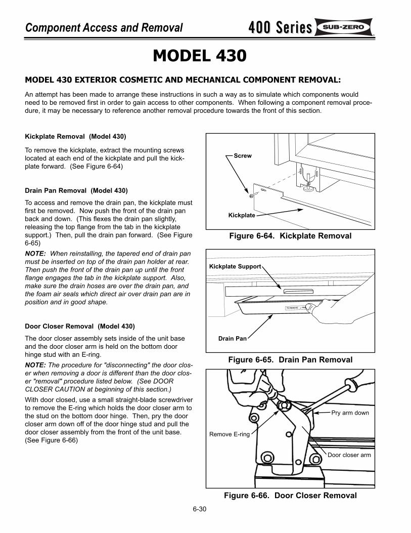
TO REMOVE PRE
Figure 6-65. Drain Pan Removal
Figure 6-66. Door Closer Removal
Remove E-ring
Pry arm down
Door closer arm
400 Series400 SeriesComponent Access and Removal
6-30
Kickplate Removal (Model 430)
To remove the kickplate, extract the mounting screwslocated at each end of the kickplate and pull the kick-plate forward. (See Figure 6-64)
Drain Pan Removal (Model 430)
To access and remove the drain pan, the kickplate mustfirst be removed. Now push the front of the drain panback and down. (This flexes the drain pan slightly,releasing the top flange from the tab in the kickplatesupport.) Then, pull the drain pan forward. (See Figure6-65)NOTE: When reinstalling, the tapered end of drain panmust be inserted on top of the drain pan holder at rear.Then push the front of the drain pan up until the frontflange engages the tab in the kickplate support. Also,make sure the drain hoses are over the drain pan, andthe foam air seals which direct air over drain pan are inposition and in good shape.
Door Closer Removal (Model 430)
The door closer assembly sets inside of the unit baseand the door closer arm is held on the bottom doorhinge stud with an E-ring. NOTE: The procedure for "disconnecting" the door clos-er when removing a door is different than the door clos-er "removal" procedure listed below. (See DOORCLOSER CAUTION at beginning of this section.)With door closed, use a small straight-blade screwdriverto remove the E-ring which holds the door closer arm tothe stud on the bottom door hinge. Then, pry the doorcloser arm down off of the door hinge stud and pull thedoor closer assembly from the front of the unit base.(See Figure 6-66)
Figure 6-64. Kickplate Removal
Kickplate
Screw
Drain Pan
Kickplate Support
MODEL 430MODEL 430 EXTERIOR COSMETIC AND MECHANICAL COMPONENT REMOVAL:
An attempt has been made to arrange these instructions in such a way as to simulate which components wouldneed to be removed first in order to gain access to other components. When following a component removal proce-dure, it may be necessary to reference another removal procedure towards the front of this section.
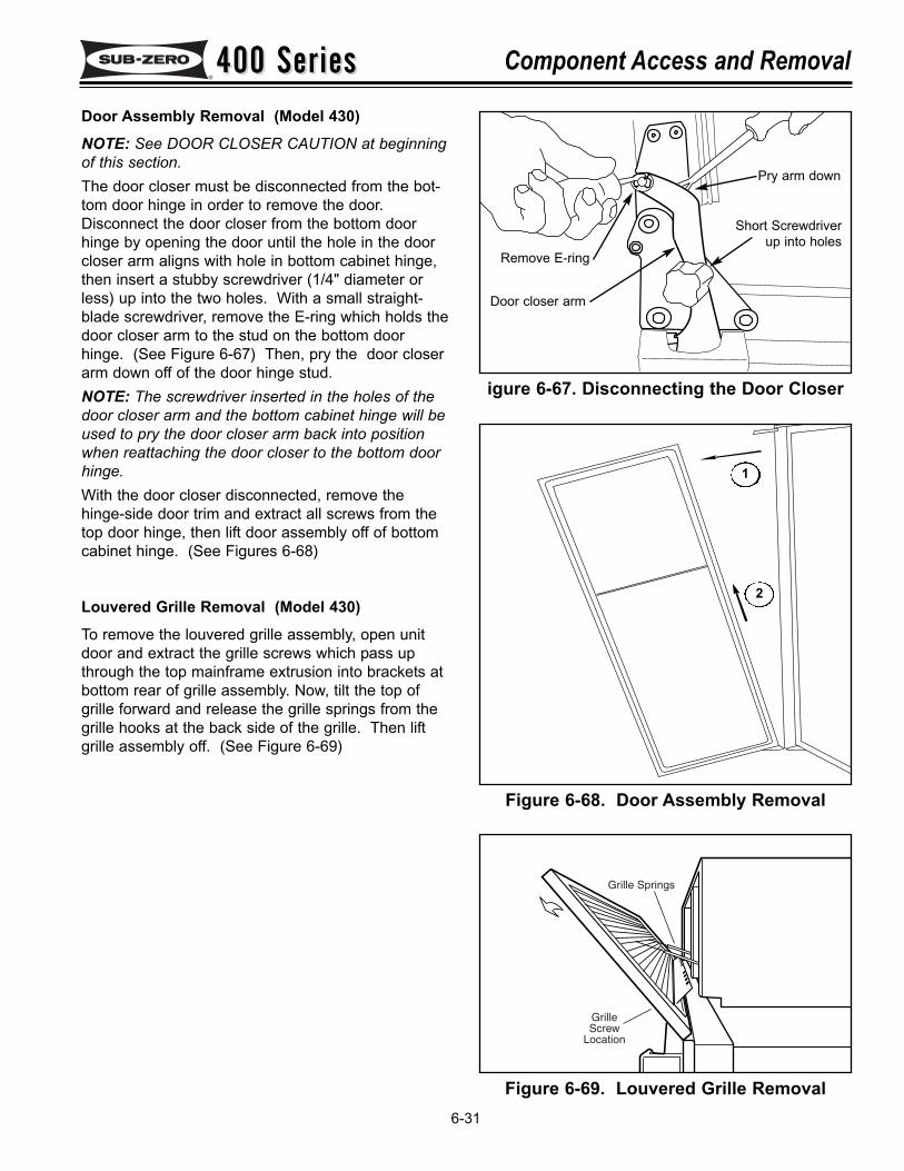
400 Series400 Series Component Access and Removal
6-31
igure 6-67. Disconnecting the Door Closer
Figure 6-68. Door Assembly Removal
1
2
Door Assembly Removal (Model 430)NOTE: See DOOR CLOSER CAUTION at beginningof this section. The door closer must be disconnected from the bot-tom door hinge in order to remove the door.Disconnect the door closer from the bottom doorhinge by opening the door until the hole in the doorcloser arm aligns with hole in bottom cabinet hinge,then insert a stubby screwdriver (1/4" diameter orless) up into the two holes. With a small straight-blade screwdriver, remove the E-ring which holds thedoor closer arm to the stud on the bottom doorhinge. (See Figure 6-67) Then, pry the door closerarm down off of the door hinge stud.NOTE: The screwdriver inserted in the holes of thedoor closer arm and the bottom cabinet hinge will beused to pry the door closer arm back into positionwhen reattaching the door closer to the bottom doorhinge.With the door closer disconnected, remove thehinge-side door trim and extract all screws from thetop door hinge, then lift door assembly off of bottomcabinet hinge. (See Figures 6-68)
Louvered Grille Removal (Model 430)To remove the louvered grille assembly, open unitdoor and extract the grille screws which pass upthrough the top mainframe extrusion into brackets atbottom rear of grille assembly. Now, tilt the top ofgrille forward and release the grille springs from thegrille hooks at the back side of the grille. Then liftgrille assembly off. (See Figure 6-69)
Remove E-ring
Pry arm down
Door closer arm
Short Screwdriverup into holes
Figure 6-69. Louvered Grille Removal
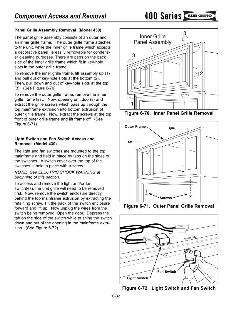
400 Series400 SeriesComponent Access and Removal
6-32
Panel Grille Assembly Removal (Model 430)The panel grille assembly consists of an outer andan inner grille frame. The outer grille frame attachesto the unit, while the inner grille frame(which acceptsa decorative panel) is easily removable for condens-er cleaning purposes. There are pegs on the backside of the inner grille frame which fit in key-holeslots in the outer grille frame.To remove the inner grille frame, lift assembly up (1)and pull out of key-hole slots at the bottom (2).Then, pull down and out of key-hole slots at the top(3). (See Figure 6-70)To remove the outer grille frame, remove the innergrille frame first. Now, opening unit door(s) andextract the grille screws which pass up through thetop mainframe extrusion into bottom extrusion ofouter grille frame. Now, extract the screws at the topfront of outer grille frame and lift frame off. (SeeFigure 6-71)
Light Switch and Fan Switch Access andRemoval (Model 430)The light and fan switches are mounted to the topmainframe and held in place by tabs on the sides ofthe switches. A switch cover over the top of theswitches is held in place with a screw.NOTE: See ELECTRIC SHOCK WARNING atbeginning of this section.To access and remove the light and/or fanswitch(es), the unit grille will need to be removedfirst. Now, remove the switch enclosure directlybehind the top mainframe extrusion by extracting theretaining screw. Tilt the back of the switch enclosureforward and lift up. Now unplug the wires from theswitch being removed. Open the door. Depress thetab on the side of the switch while pushing the switchdown and out of the opening in the mainframe extru-sion. (See Figure 6-72)
Figure 6-72. Light Switch and Fan Switch
Figure 6-70. Inner Panel Grille Removal
Figure 6-71. Outer Panel Grille Removal
Outer Frame
Screws
Light Switch
Fan Switch
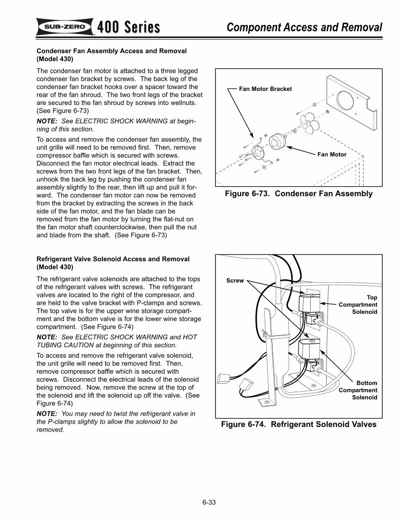
400 Series400 Series Component Access and Removal
6-33
Condenser Fan Assembly Access and Removal(Model 430)
The condenser fan motor is attached to a three leggedcondenser fan bracket by screws. The back leg of thecondenser fan bracket hooks over a spacer toward therear of the fan shroud. The two front legs of the bracketare secured to the fan shroud by screws into wellnuts.(See Figure 6-73) NOTE: See ELECTRIC SHOCK WARNING at begin-ning of this section.To access and remove the condenser fan assembly, theunit grille will need to be removed first. Then, removecompressor baffle which is secured with screws.Disconnect the fan motor electrical leads. Extract thescrews from the two front legs of the fan bracket. Then,unhook the back leg by pushing the condenser fanassembly slightly to the rear, then lift up and pull it for-ward. The condenser fan motor can now be removedfrom the bracket by extracting the screws in the backside of the fan motor, and the fan blade can beremoved from the fan motor by turning the flat-nut onthe fan motor shaft counterclockwise, then pull the nutand blade from the shaft. (See Figure 6-73)
Refrigerant Valve Solenoid Access and Removal(Model 430)
The refrigerant valve solenoids are attached to the topsof the refrigerant valves with screws. The refrigerantvalves are located to the right of the compressor, andare held to the valve bracket with P-clamps and screws.The top valve is for the upper wine storage compart-ment and the bottom valve is for the lower wine storagecompartment. (See Figure 6-74)NOTE: See ELECTRIC SHOCK WARNING and HOTTUBING CAUTION at beginning of this section.To access and remove the refrigerant valve solenoid,the unit grille will need to be removed first. Then,remove compressor baffle which is secured withscrews. Disconnect the electrical leads of the solenoidbeing removed. Now, remove the screw at the top ofthe solenoid and lift the solenoid up off the valve. (SeeFigure 6-74)NOTE: You may need to twist the refrigerant valve inthe P-clamps slightly to allow the solenoid to beremoved.
Figure 6-73. Condenser Fan Assembly
Figure 6-74. Refrigerant Solenoid Valves
TopCompartment
Solenoid
BottomCompartment
Solenoid
Screw
Fan Motor
Fan Motor Bracket
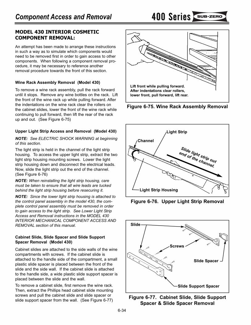
400 Series400 SeriesComponent Access and Removal
6-34
MODEL 430 INTERIOR COSMETIC COMPONENT REMOVAL:
An attempt has been made to arrange these instructionsin such a way as to simulate which components wouldneed to be removed first in order to gain access to othercomponents. When following a component removal pro-cedure, it may be necessary to reference anotherremoval procedure towards the front of this section.
Wine Rack Assembly Removal (Model 430)
To remove a wine rack assembly, pull the rack forwarduntil it stops. Remove any wine bottles on the rack. Liftthe front of the wine rack up while pulling forward. Afterthe indentations on the wine rack clear the rollers onthe cabinet slides, lower the front of the wine rack whilecontinuing to pull forward, then lift the rear of the rackup and out. (See Figure 6-75)
Upper Light Strip Access and Removal (Model 430)
NOTE: See ELECTRIC SHOCK WARNING at beginningof this section.The light strip is held in the channel of the light striphousing. To access the upper light strip, extract the twolight strip housing mounting screws. Lower the lightstrip housing down and disconnect the electrical leads.Now, slide the light strip out the end of the channel.(See Figure 6-76)NOTE: When reinstalling the light strip housing, caremust be taken to ensure that all wire leads are tuckedbehind the light strip housing before resecuring it.NOTE: Since the lower light strip housing is attached tothe control panel assembly in the model 430, the com-plete control panel assembly must be removed in orderto gain access to the light strip. See Lower Light StripAccess and Removal instructions in the MODEL 430INTERIOR MECHANICAL COMPONENT ACCESS ANDREMOVAL section of this manual.
Cabinet Slide, Slide Spacer and Slide SupportSpacer Removal (Model 430)
Cabinet slides are attached to the side walls of the winecompartments with screws. If the cabinet slide isattached to the handle side of the compartment, a smallplastic slide spacer is placed between the front of theslide and the side wall. If the cabinet slide is attachedto the handle side, a wide plastic slide support spacer isplaced between the slide and the wall.To remove a cabinet slide, first remove the wine rack.Then, extract the Phillips head cabinet slide mountingscrews and pull the cabinet slide and slide spacer orslide support spacer from the wall. (See Figure 6-77)
Figure 6-76. Upper Light Strip Removal
Figure 6-75. Wine Rack Assembly Removal
Figure 6-77. Cabinet Slide, Slide SupportSpacer & Slide Spacer Removal
Slide light strip out
end of the channel.
Channel
Light Strip
Light Strip Housing
Slide Support Spacer
Slide
Screws
Slide Spacer
Lift front while pulling forward.After indentations clear rollers,lower front, pull forward, lift rear.
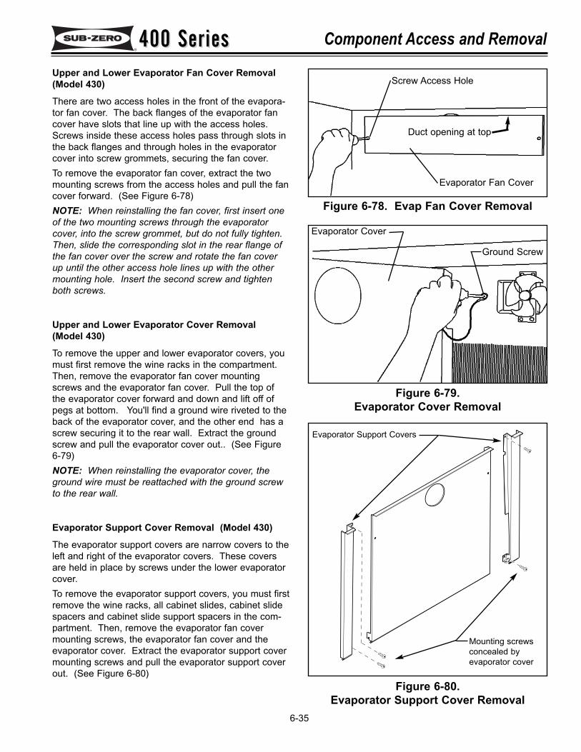
400 Series400 Series Component Access and Removal
6-35
Upper and Lower Evaporator Fan Cover Removal(Model 430)
There are two access holes in the front of the evapora-tor fan cover. The back flanges of the evaporator fancover have slots that line up with the access holes.Screws inside these access holes pass through slots inthe back flanges and through holes in the evaporatorcover into screw grommets, securing the fan cover.To remove the evaporator fan cover, extract the twomounting screws from the access holes and pull the fancover forward. (See Figure 6-78)NOTE: When reinstalling the fan cover, first insert oneof the two mounting screws through the evaporatorcover, into the screw grommet, but do not fully tighten.Then, slide the corresponding slot in the rear flange ofthe fan cover over the screw and rotate the fan coverup until the other access hole lines up with the othermounting hole. Insert the second screw and tightenboth screws.
Upper and Lower Evaporator Cover Removal(Model 430)
To remove the upper and lower evaporator covers, youmust first remove the wine racks in the compartment.Then, remove the evaporator fan cover mountingscrews and the evaporator fan cover. Pull the top ofthe evaporator cover forward and down and lift off ofpegs at bottom. You'll find a ground wire riveted to theback of the evaporator cover, and the other end has ascrew securing it to the rear wall. Extract the groundscrew and pull the evaporator cover out.. (See Figure6-79)NOTE: When reinstalling the evaporator cover, theground wire must be reattached with the ground screwto the rear wall.
Evaporator Support Cover Removal (Model 430)
The evaporator support covers are narrow covers to theleft and right of the evaporator covers. These coversare held in place by screws under the lower evaporatorcover. To remove the evaporator support covers, you must firstremove the wine racks, all cabinet slides, cabinet slidespacers and cabinet slide support spacers in the com-partment. Then, remove the evaporator fan covermounting screws, the evaporator fan cover and theevaporator cover. Extract the evaporator support covermounting screws and pull the evaporator support coverout. (See Figure 6-80)
Figure 6-78. Evap Fan Cover Removal
Figure 6-79.Evaporator Cover Removal
Figure 6-80.Evaporator Support Cover Removal
Duct opening at top
Evaporator Fan Cover
Screw Access Hole
Evaporator Cover
Ground Screw
Evaporator Support Covers
Mounting screws concealed by evaporator cover
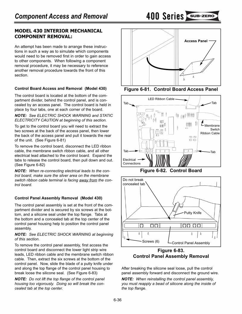
400 Series400 SeriesComponent Access and Removal
6-36
After breaking the silicone seal loose, pull the controlpanel assembly forward and disconnect the ground wire.NOTE: When reinstalling the control panel assembly,you must reapply a bead of silicone along the inside ofthe top flange.
MODEL 430 INTERIOR MECHANICALCOMPONENT REMOVAL:
An attempt has been made to arrange these instruc-tions in such a way as to simulate which componentswould need to be removed first in order to gain accessto other components. When following a componentremoval procedure, it may be necessary to referenceanother removal procedure towards the front of thissection.
Control Board Access and Removal (Model 430)
The control board is located at the bottom of the com-partment divider, behind the control panel, and is con-cealed by an access panel. The control board is held inplace by four tabs, one at each corner of the board.NOTE: See ELECTRIC SHOCK WARNING and STATICELECTRICITY CAUTION at beginning of this section.To get to the control board you will need to extract thetwo screws at the back of the access panel, then lowerthe back of the access panel and pull it towards the rearof the unit. (See Figure 6-81)To remove the control board, disconnect the LED ribboncable, the membrane switch ribbon cable, and all otherelectrical lead attached to the control board. Expand thetabs to release the control board, then pull down and out.(See Figure 6-82)NOTE: When re-connecting electrical leads to the con-trol board, make sure the silver area on the membraneswitch ribbon cable terminal is facing away from the con-trol board.
Control Panel Assembly Removal (Model 430)
The control panel assembly is set at the front of the com-partment divider and is secured by six screws at the bot-tom, and a silicone seal under the top flange. Tabs atthe bottom and a concealed tab at the top center of thecontrol panel housing help to position the control panelassembly.NOTE: See ELECTRIC SHOCK WARNING at beginningof this section.To remove the control panel assembly, first access thecontrol board and disconnect the lower light strip wireleads, LED ribbon cable and the membrane switch ribboncable. Then, extract the six screws at the bottom of thecontrol panel. Now, slide the blade of a putty knife underand along the top flange of the control panel housing tobreak loose the silicone seal. (See Figure 6-83)NOTE: Do not lift the top flange of the control panelhousing too vigorously. Doing so will break the con-cealed tab at the top center.
Figure 6-81. Control Board Access Panel
Figure 6-82. Control Board
Figure 6-83.Control Panel Assembly Removal
Tab
LED Ribbon Cable
MembraneSwitch
Ribbon Cable
ElectricalConnections
Tab
TabTab
Control Panel Assembly
Putty Knife
Screws (6)
Do not breakconcealed tab
Access Panel
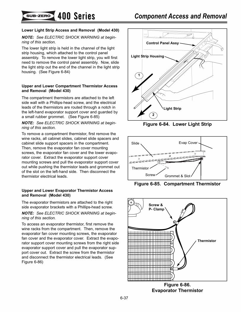
400 Series400 Series Component Access and Removal
6-37
Figure 6-85. Compartment Thermistor
Figure 6-86.Evaporator Thermistor
Thermistor
Evap Cover
Screw
Slide
Grommet & Slot
Screw &P- Clamp
Thermistor
Lower Light Strip Access and Removal (Model 430)
NOTE: See ELECTRIC SHOCK WARNING at begin-ning of this section.The lower light strip is held in the channel of the lightstrip housing, which attached to the control panelassembly. To remove the lower light strip, you will firstneed to remove the control panel assembly. Now, slidethe light strip out the end of the channel in the light striphousing. (See Figure 6-84)
Upper and Lower Compartment Thermistor Accessand Removal (Model 430)
The compartment thermistors are attached to the leftside wall with a Phillips-head screw, and the electricalleads of the thermistors are routed through a notch inthe left-hand evaporator support cover and guarded bya small rubber grommet. (See Figure 6-85)NOTE: See ELECTRIC SHOCK WARNING at begin-ning of this section.To remove a compartment thermistor, first remove thewine racks, all cabinet slides, cabinet slide spacers andcabinet slide support spacers in the compartment.Then, remove the evaporator fan cover mountingscrews, the evaporator fan cover and the lower evapo-rator cover. Extract the evaporator support covermounting screws and pull the evaporator support coverout while pushing the thermistor leads and grommet outof the slot on the left-hand side. Then disconnect thethermistor electrical leads.
Upper and Lower Evaporator Thermistor Accessand Removal (Model 430)
The evaporator thermistors are attached to the rightside evaporator brackets with a Phillips-head screw.NOTE: See ELECTRIC SHOCK WARNING at begin-ning of this section.To access an evaporator thermistor, first remove thewine racks from the compartment. Then, remove theevaporator fan cover mounting screws, the evaporatorfan cover and the evaporator cover. Extract the evapo-rator support cover mounting screws from the right sideevaporator support cover and pull the evaporator sup-port cover out. Extract the screw from the thermistorand disconnect the thermistor electrical leads. (SeeFigure 6-86)
1
2
Control Panel Assy
Light Strip Housing
Light Strip
Figure 6-84. Lower Light Strip
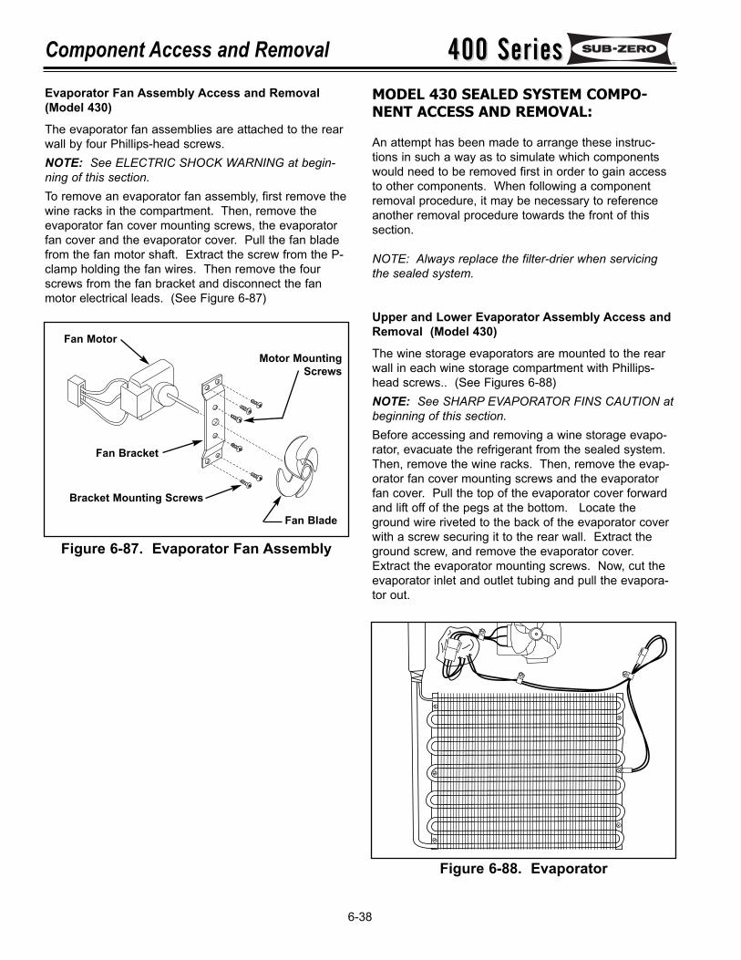
400 Series400 SeriesComponent Access and Removal
6-38
MODEL 430 SEALED SYSTEM COMPO-NENT ACCESS AND REMOVAL:
An attempt has been made to arrange these instruc-tions in such a way as to simulate which componentswould need to be removed first in order to gain accessto other components. When following a componentremoval procedure, it may be necessary to referenceanother removal procedure towards the front of thissection.
NOTE: Always replace the filter-drier when servicingthe sealed system.
Upper and Lower Evaporator Assembly Access andRemoval (Model 430)
The wine storage evaporators are mounted to the rearwall in each wine storage compartment with Phillips-head screws.. (See Figures 6-88)NOTE: See SHARP EVAPORATOR FINS CAUTION atbeginning of this section.Before accessing and removing a wine storage evapo-rator, evacuate the refrigerant from the sealed system.Then, remove the wine racks. Then, remove the evap-orator fan cover mounting screws and the evaporatorfan cover. Pull the top of the evaporator cover forwardand lift off of the pegs at the bottom. Locate theground wire riveted to the back of the evaporator coverwith a screw securing it to the rear wall. Extract theground screw, and remove the evaporator cover.Extract the evaporator mounting screws. Now, cut theevaporator inlet and outlet tubing and pull the evapora-tor out.
Figure 6-87. Evaporator Fan Assembly
Figure 6-88. Evaporator
Fan Motor
Fan Bracket
Motor MountingScrews
Bracket Mounting Screws
Fan Blade
Evaporator Fan Assembly Access and Removal(Model 430)
The evaporator fan assemblies are attached to the rearwall by four Phillips-head screws.NOTE: See ELECTRIC SHOCK WARNING at begin-ning of this section.To remove an evaporator fan assembly, first remove thewine racks in the compartment. Then, remove theevaporator fan cover mounting screws, the evaporatorfan cover and the evaporator cover. Pull the fan bladefrom the fan motor shaft. Extract the screw from the P-clamp holding the fan wires. Then remove the fourscrews from the fan bracket and disconnect the fanmotor electrical leads. (See Figure 6-87)
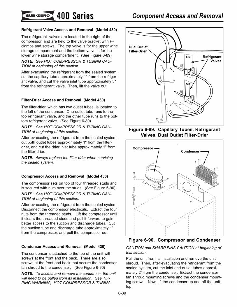
400 Series400 Series Component Access and Removal
6-39
Refrigerant Valve Access and Removal (Model 430)
The refrigerant valves are located to the right of thecompressor, and are held to the valve bracket with P-clamps and screws. The top valve is for the upper winestorage compartment and the bottom valve is for thelower wine storage compartment. (See Figure 6-89)NOTE: See HOT COMPRESSOR & TUBING CAU-TION at beginning of this section.After evacuating the refrigerant from the sealed system,cut the capillary tube approximately 1" from the refriger-ant valve, and cut the valve inlet tube approximately 3"from the refrigerant valve. Then, lift the valve out.
Filter-Drier Access and Removal (Model 430)
The filter-drier, which has two outlet tubes, is located tothe left of the condenser. One outlet tube runs to thetop refrigerant valve, and the other tube runs to the bot-tom refrigerant valve. (See Figure 6-89)NOTE: See HOT COMPRESSOR & TUBING CAU-TION at beginning of this section.After evacuating the refrigerant from the sealed system,cut both outlet tubes approximately 1" from the filter-drier, and cut the drier inlet tube approximately 1" fromthe filter-drier.NOTE: Always replace the filter-drier when servicingthe sealed system.
Compressor Access and Removal (Model 430)
The compressor sets on top of four threaded studs andis secured with nuts over the studs. (See Figure 6-90)NOTE: See HOT COMPRESSOR & TUBING CAU-TION at beginning of this section.After evacuating the refrigerant from the sealed system,Disconnect the compressor electricals. Extract the fournuts from the threaded studs. Lift the compressor untilit clears the threaded studs and pull it forward to gainbetter access to the suction and discharge tubes. Cutthe suction tube and discharge tube approximately 1"from the compressor, and pull the compressor out.
Condenser Access and Removal (Model 430)
The condenser is attached to the top of the unit withscrews at the front and the back. There are alsoscrews at the front and back that secure the condenserfan shroud to the condenser. (See Figure 6-90)NOTE: To access and remove the condenser, the unitwill need to be pulled from its installation. See TIP-PING WARNING, HOT COMPRESSOR & TUBING
CAUTION and SHARP FINS CAUTION at beginning ofthis section.Pull the unit from its installation and remove the unitshroud. Then, after evacuating the refrigerant from thesealed system, cut the inlet and outlet tubes approxi-mately 2" from the condenser. Extract the condenserfan shroud mounting screws and the condenser mount-ing screws. Now, lift the condenser up and off the unittop.
Figure 6-90. Compressor and Condenser
Figure 6-89. Capillary Tubes, RefrigerantValves, Dual Outlet Filter-Drier
Dual OutletFilter-Drier
RefrigerantValves
CompressorCondenser
400 Series400 SeriesComponent Access and Removal Notes
6-40
400 Series400 Series Parts Lists & Exploded Views
7-1
SECTION 7
PARTS LISTS &EXPLODED VIEWS
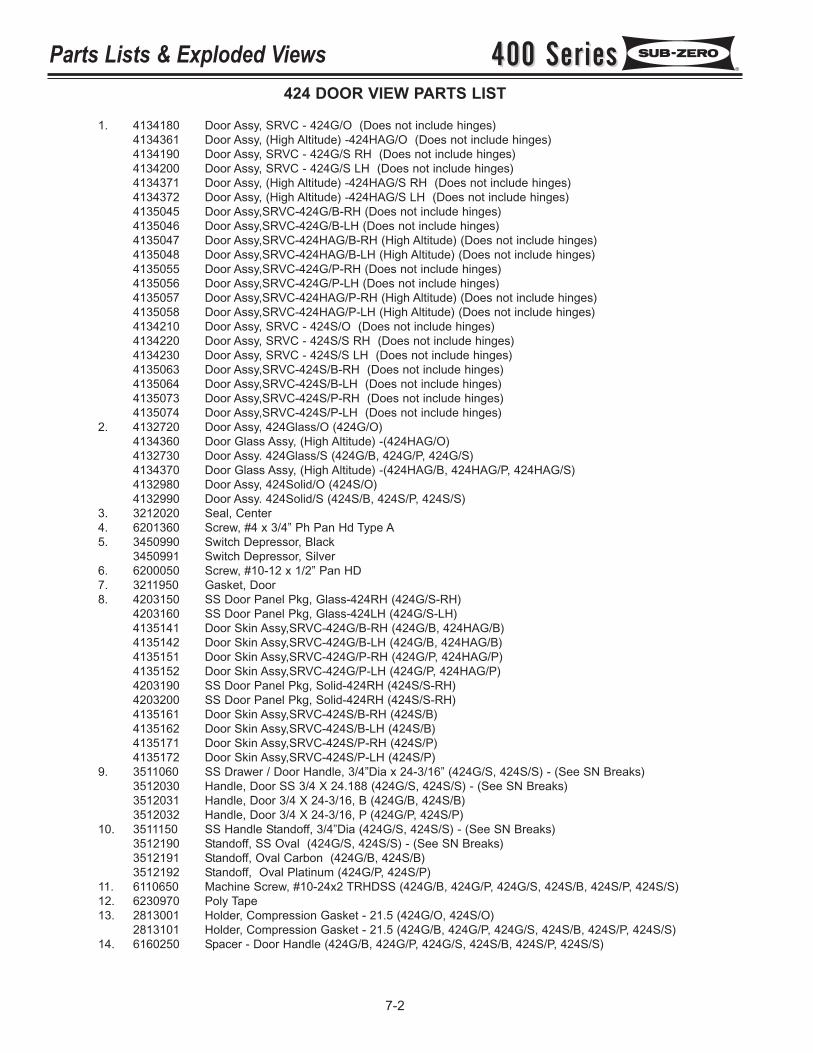
400 Series400 SeriesParts Lists & Exploded Views
7-2
424 DOOR VIEW PARTS LIST
1. 4134180 Door Assy, SRVC - 424G/O (Does not include hinges)4134361 Door Assy, (High Altitude) -424HAG/O (Does not include hinges)4134190 Door Assy, SRVC - 424G/S RH (Does not include hinges)4134200 Door Assy, SRVC - 424G/S LH (Does not include hinges)4134371 Door Assy, (High Altitude) -424HAG/S RH (Does not include hinges)4134372 Door Assy, (High Altitude) -424HAG/S LH (Does not include hinges)4135045 Door Assy,SRVC-424G/B-RH (Does not include hinges)4135046 Door Assy,SRVC-424G/B-LH (Does not include hinges)4135047 Door Assy,SRVC-424HAG/B-RH (High Altitude) (Does not include hinges)4135048 Door Assy,SRVC-424HAG/B-LH (High Altitude) (Does not include hinges)4135055 Door Assy,SRVC-424G/P-RH (Does not include hinges)4135056 Door Assy,SRVC-424G/P-LH (Does not include hinges)4135057 Door Assy,SRVC-424HAG/P-RH (High Altitude) (Does not include hinges)4135058 Door Assy,SRVC-424HAG/P-LH (High Altitude) (Does not include hinges)4134210 Door Assy, SRVC - 424S/O (Does not include hinges)4134220 Door Assy, SRVC - 424S/S RH (Does not include hinges)4134230 Door Assy, SRVC - 424S/S LH (Does not include hinges)4135063 Door Assy,SRVC-424S/B-RH (Does not include hinges)4135064 Door Assy,SRVC-424S/B-LH (Does not include hinges)4135073 Door Assy,SRVC-424S/P-RH (Does not include hinges)4135074 Door Assy,SRVC-424S/P-LH (Does not include hinges)
2. 4132720 Door Assy, 424Glass/O (424G/O)4134360 Door Glass Assy, (High Altitude) -(424HAG/O)4132730 Door Assy. 424Glass/S (424G/B, 424G/P, 424G/S)4134370 Door Glass Assy, (High Altitude) -(424HAG/B, 424HAG/P, 424HAG/S)4132980 Door Assy, 424Solid/O (424S/O)4132990 Door Assy. 424Solid/S (424S/B, 424S/P, 424S/S)
3. 3212020 Seal, Center4. 6201360 Screw, #4 x 3/4” Ph Pan Hd Type A5. 3450990 Switch Depressor, Black
3450991 Switch Depressor, Silver6. 6200050 Screw, #10-12 x 1/2” Pan HD7. 3211950 Gasket, Door8. 4203150 SS Door Panel Pkg, Glass-424RH (424G/S-RH)
4203160 SS Door Panel Pkg, Glass-424LH (424G/S-LH)4135141 Door Skin Assy,SRVC-424G/B-RH (424G/B, 424HAG/B)4135142 Door Skin Assy,SRVC-424G/B-LH (424G/B, 424HAG/B)4135151 Door Skin Assy,SRVC-424G/P-RH (424G/P, 424HAG/P)4135152 Door Skin Assy,SRVC-424G/P-LH (424G/P, 424HAG/P)4203190 SS Door Panel Pkg, Solid-424RH (424S/S-RH)4203200 SS Door Panel Pkg, Solid-424RH (424S/S-RH)4135161 Door Skin Assy,SRVC-424S/B-RH (424S/B)4135162 Door Skin Assy,SRVC-424S/B-LH (424S/B)4135171 Door Skin Assy,SRVC-424S/P-RH (424S/P)4135172 Door Skin Assy,SRVC-424S/P-LH (424S/P)
9. 3511060 SS Drawer / Door Handle, 3/4”Dia x 24-3/16” (424G/S, 424S/S) - (See SN Breaks)3512030 Handle, Door SS 3/4 X 24.188 (424G/S, 424S/S) - (See SN Breaks)3512031 Handle, Door 3/4 X 24-3/16, B (424G/B, 424S/B)3512032 Handle, Door 3/4 X 24-3/16, P (424G/P, 424S/P)
10. 3511150 SS Handle Standoff, 3/4”Dia (424G/S, 424S/S) - (See SN Breaks)3512190 Standoff, SS Oval (424G/S, 424S/S) - (See SN Breaks)3512191 Standoff, Oval Carbon (424G/B, 424S/B)3512192 Standoff, Oval Platinum (424G/P, 424S/P)
11. 6110650 Machine Screw, #10-24x2 TRHDSS (424G/B, 424G/P, 424G/S, 424S/B, 424S/P, 424S/S)12. 6230970 Poly Tape13. 2813001 Holder, Compression Gasket - 21.5 (424G/O, 424S/O)
2813101 Holder, Compression Gasket - 21.5 (424G/B, 424G/P, 424G/S, 424S/B, 424S/P, 424S/S)14. 6160250 Spacer - Door Handle (424G/B, 424G/P, 424G/S, 424S/B, 424S/P, 424S/S)
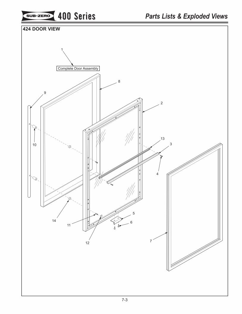
1
Complete Door Assembly
2
3
4
5
6
7
8
9
10
11
12
13
14
400 Series400 Series Parts Lists & Exploded Views
7-3
424 DOOR VIEW
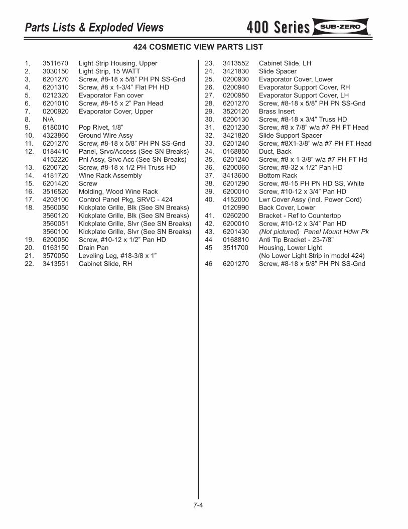
400 Series400 SeriesParts Lists & Exploded Views
7-4
424 COSMETIC VIEW PARTS LIST
1. 3511670 Light Strip Housing, Upper2. 3030150 Light Strip, 15 WATT3. 6201270 Screw, #8-18 x 5/8” PH PN SS-Gnd4. 6201310 Screw, #8 x 1-3/4” Flat PH HD5. 0212320 Evaporator Fan cover6. 6201010 Screw, #8-15 x 2” Pan Head7. 0200920 Evaporator Cover, Upper8. N/A9. 6180010 Pop Rivet, 1/8”10. 4323860 Ground Wire Assy11. 6201270 Screw, #8-18 x 5/8” PH PN SS-Gnd12. 0184410 Panel, Srvc/Access (See SN Breaks)
4152220 Pnl Assy, Srvc Acc (See SN Breaks)13. 6200720 Screw, #8-18 x 1/2 PH Truss HD 14. 4181720 Wine Rack Assembly15. 6201420 Screw16. 3516520 Molding, Wood Wine Rack17. 4203100 Control Panel Pkg, SRVC - 42418. 3560050 Kickplate Grille, Blk (See SN Breaks)
3560120 Kickplate Grille, Blk (See SN Breaks)3560051 Kickplate Grille, Slvr (See SN Breaks)3560100 Kickplate Grille, Slvr (See SN Breaks)
19. 6200050 Screw, #10-12 x 1/2” Pan HD20. 0163150 Drain Pan21. 3570050 Leveling Leg, #18-3/8 x 1”22. 3413551 Cabinet Slide, RH
23. 3413552 Cabinet Slide, LH24. 3421830 Slide Spacer25. 0200930 Evaporator Cover, Lower26. 0200940 Evaporator Support Cover, RH27. 0200950 Evaporator Support Cover, LH28. 6201270 Screw, #8-18 x 5/8” PH PN SS-Gnd29. 3520120 Brass Insert30. 6200130 Screw, #8-18 x 3/4” Truss HD31. 6201230 Screw, #8 x 7/8” w/a #7 PH FT Head32. 3421820 Slide Support Spacer33. 6201240 Screw, #8X1-3/8” w/a #7 PH FT Head34. 0168850 Duct, Back35. 6201240 Screw, #8 x 1-3/8” w/a #7 PH FT Hd36. 6200060 Screw, #8-32 x 1/2” Pan HD37. 3413600 Bottom Rack38. 6201290 Screw, #8-15 PH PN HD SS, White39. 6200010 Screw, #10-12 x 3/4” Pan HD40. 4152000 Lwr Cover Assy (Incl. Power Cord)
0120990 Back Cover, Lower41. 0260200 Bracket - Ref to Countertop42. 6200010 Screw, #10-12 x 3/4” Pan HD43. 6201430 (Not pictured) Panel Mount Hdwr Pk44 0168810 Anti Tip Bracket - 23-7/8"45 3511700 Housing, Lower Light
(No Lower Light Strip in model 424)46 6201270 Screw, #8-18 x 5/8” PH PN SS-Gnd
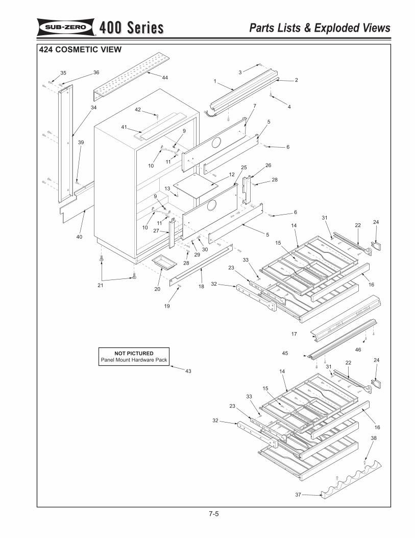
4546
35 36
34
39
40
9
1110
1
3
2
47
5
6
26
28
12
25
6
5
13
9
1011
27
28
29
30
2120
19
1832
23
33
15
14
31
2224
16
17
2422
3114
15
33
23
32
16
38
37
41
42
44
43
NOT PICTURED
Panel Mount Hardware Pack
400 Series400 Series Parts Lists & Exploded Views
7-5
424 COSMETIC VIEW
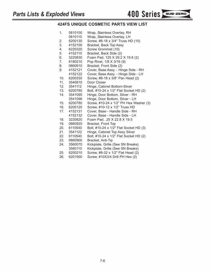
400 Series400 SeriesParts Lists & Exploded Views
7-6
424FS UNIQUE COSMETIC PARTS VIEW LIST
1. 0810100 Wrap, Stainless Overlay, RH0810110 Wrap, Stainless Overlay, LH
2. 6200130 Screw, #8-18 x 3/4" Truss HD (10)3. 4152100 Bracket, Back Top Assy4. 6220320 Screw Grommet (10)5. 4152110 Bracket, Back Side (2)6. 3220830 Foam Pad, 125 X 29.2 X 19.8 (2)7. 6180210 Pop Rivet, 1/8 X 3/16 (9)8. 0860910 Bracket, Front Side (2)9. 4152121 Cover, Base Assy. - Hinge Side - RH
4152122 Cover, Base Assy. - Hinge Side - LH10. 6200330 Screw, #8-18 x 3/8” Pan Head (2)11. 3540810 Door Closer12. 3541112 Hinge, Cabinet Bottom-Silver13. 6200780 Bolt, #10-24 x 1/2” Flat Socket HD (2)14. 3541095 Hinge, Door Bottom, Silver - RH
3541096 Hinge, Door Bottom, Silver - LH15. 6200780 Screw, #10-24 x 1/2” PH Hex Washer (3)16. 6200120 Screw, #10-12 x 1/2" Truss HD17. 4152131 Cover, Base - Handle Side - RH
4152132 Cover, Base - Handle Side - LH18. 3220820 Foam Pad, .25 X 22.8 X 19.519. 0860920 Bracket, Front Top20. 6110540 Bolt, #10-24 x 1/2" Flat Socket HD (3)21. 3541122 Hinge, Cabinet Top Assy Silver22. 6110540 Bolt, #10-24 x 1/2” Flat Socket HD (2)23. 0860900 Bracket, Anti-Tip24. 3560070 Kickplate, Grille (See SN Breaks)
3560110 Kickplate, Grille (See SN Breaks)25. 6200210 Screw, #8-32 x 1/2" Flat Head (2)26. 6201500 Screw, #10X3/4 Drill PH Hex (2)
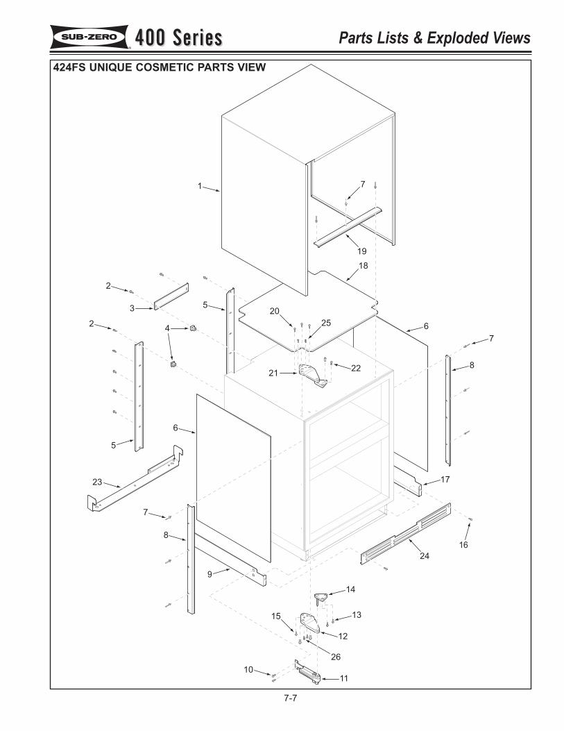
3
4
1
9
11
12
13
14
2
2
5
5
6
7
8
10
15
17
8
7
6
18
19
23
16
24
26
2122
7
20
25
400 Series400 Series Parts Lists & Exploded Views
7-7
424FS UNIQUE COSMETIC PARTS VIEW
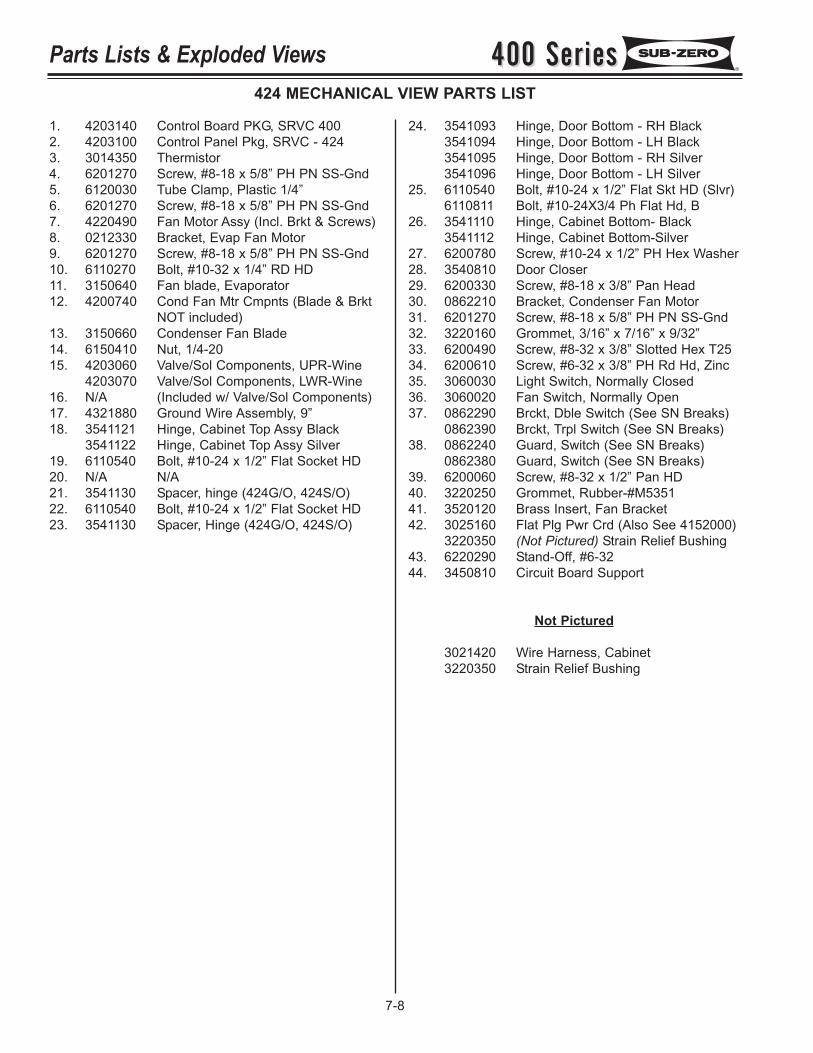
400 Series400 SeriesParts Lists & Exploded Views
7-8
424 MECHANICAL VIEW PARTS LIST
1. 4203140 Control Board PKG, SRVC 4002. 4203100 Control Panel Pkg, SRVC - 4243. 3014350 Thermistor4. 6201270 Screw, #8-18 x 5/8” PH PN SS-Gnd5. 6120030 Tube Clamp, Plastic 1/4”6. 6201270 Screw, #8-18 x 5/8” PH PN SS-Gnd7. 4220490 Fan Motor Assy (Incl. Brkt & Screws)8. 0212330 Bracket, Evap Fan Motor9. 6201270 Screw, #8-18 x 5/8” PH PN SS-Gnd10. 6110270 Bolt, #10-32 x 1/4” RD HD11. 3150640 Fan blade, Evaporator12. 4200740 Cond Fan Mtr Cmpnts (Blade & Brkt
NOT included)13. 3150660 Condenser Fan Blade14. 6150410 Nut, 1/4-2015. 4203060 Valve/Sol Components, UPR-Wine
4203070 Valve/Sol Components, LWR-Wine16. N/A (Included w/ Valve/Sol Components)17. 4321880 Ground Wire Assembly, 9”18. 3541121 Hinge, Cabinet Top Assy Black
3541122 Hinge, Cabinet Top Assy Silver19. 6110540 Bolt, #10-24 x 1/2” Flat Socket HD20. N/A N/A21. 3541130 Spacer, hinge (424G/O, 424S/O)22. 6110540 Bolt, #10-24 x 1/2” Flat Socket HD23. 3541130 Spacer, Hinge (424G/O, 424S/O)
24. 3541093 Hinge, Door Bottom - RH Black3541094 Hinge, Door Bottom - LH Black3541095 Hinge, Door Bottom - RH Silver3541096 Hinge, Door Bottom - LH Silver
25. 6110540 Bolt, #10-24 x 1/2” Flat Skt HD (Slvr)6110811 Bolt, #10-24X3/4 Ph Flat Hd, B
26. 3541110 Hinge, Cabinet Bottom- Black3541112 Hinge, Cabinet Bottom-Silver
27. 6200780 Screw, #10-24 x 1/2” PH Hex Washer28. 3540810 Door Closer29. 6200330 Screw, #8-18 x 3/8” Pan Head30. 0862210 Bracket, Condenser Fan Motor31. 6201270 Screw, #8-18 x 5/8” PH PN SS-Gnd32. 3220160 Grommet, 3/16” x 7/16” x 9/32”33. 6200490 Screw, #8-32 x 3/8” Slotted Hex T2534. 6200610 Screw, #6-32 x 3/8” PH Rd Hd, Zinc35. 3060030 Light Switch, Normally Closed36. 3060020 Fan Switch, Normally Open37. 0862290 Brckt, Dble Switch (See SN Breaks)
0862390 Brckt, Trpl Switch (See SN Breaks)38. 0862240 Guard, Switch (See SN Breaks)
0862380 Guard, Switch (See SN Breaks)39. 6200060 Screw, #8-32 x 1/2” Pan HD40. 3220250 Grommet, Rubber-#M535141. 3520120 Brass Insert, Fan Bracket42. 3025160 Flat Plg Pwr Crd (Also See 4152000)
3220350 (Not Pictured) Strain Relief Bushing43. 6220290 Stand-Off, #6-3244. 3450810 Circuit Board Support
Not Pictured
3021420 Wire Harness, Cabinet3220350 Strain Relief Bushing
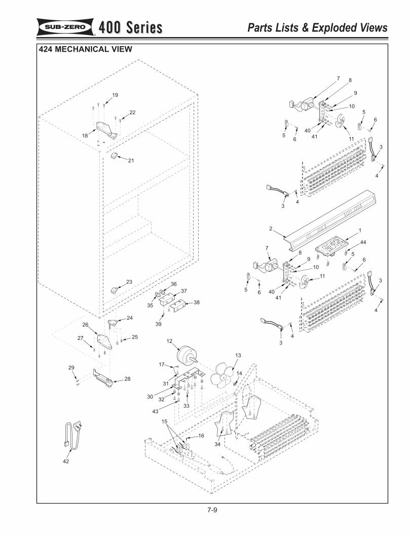
7 8
9
10
5
6
3
4
11
40
4156
34
2 1
44
8
9
10
11
5
6
40
41
56
7
3
4
4
3
36
35
39
38
37
24
27
28
29
12
17
31
3230
43
33
15
13
14
34
16
42
19
18
21
22
23
26
25
400 Series400 Series Parts Lists & Exploded Views
7-9
424 MECHANICAL VIEW
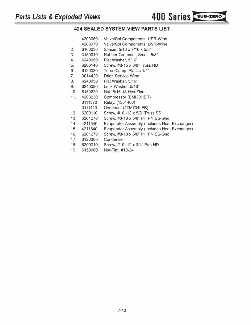
400 Series400 SeriesParts Lists & Exploded Views
7-10
424 SEALED SYSTEM VIEW PARTS LIST
1. 4203060 Valve/Sol Components, UPR-Wine4203070 Valve/Sol Components, LWR-Wine
2. 6160030 Spacer, 5/16 x 7/16 x 5/8”3. 3150010 Rubber Grommet, Small, 5/8”4. 6240050 Flat Washer, 5/16”5. 6200140 Screw, #8-15 x 3/8” Truss HD6. 6120030 Tube Clamp, Plastic 1/4”7. 3014420 Drier, Service Wine8. 6240050 Flat Washer, 5/16”9. 6240090 Lock Washer, 5/16”10. 6150220 Nut, 5/16-18 Hex Zinc11. 4203230 Compressor (EMI30HER)
3111370 Relay, (1351400)3111410 Overload, (4TM734LFB)
12. 6200110 Screw, #10 -12 x 5/8” Truss SS13. 6201270 Screw, #8-18 x 5/8” PH PN SS-Gnd14. 4211540 Evaporator Assembly (Includes Heat Exchanger)15. 4211540 Evaporator Assembly (Includes Heat Exchanger)16. 6201270 Screw, #8-18 x 5/8” PH PN SS-Gnd17. 3120300 Condenser18. 6200010 Screw, #10 -12 x 3/4” Pan HD19. 6150080 Nut-Flat, #10-24
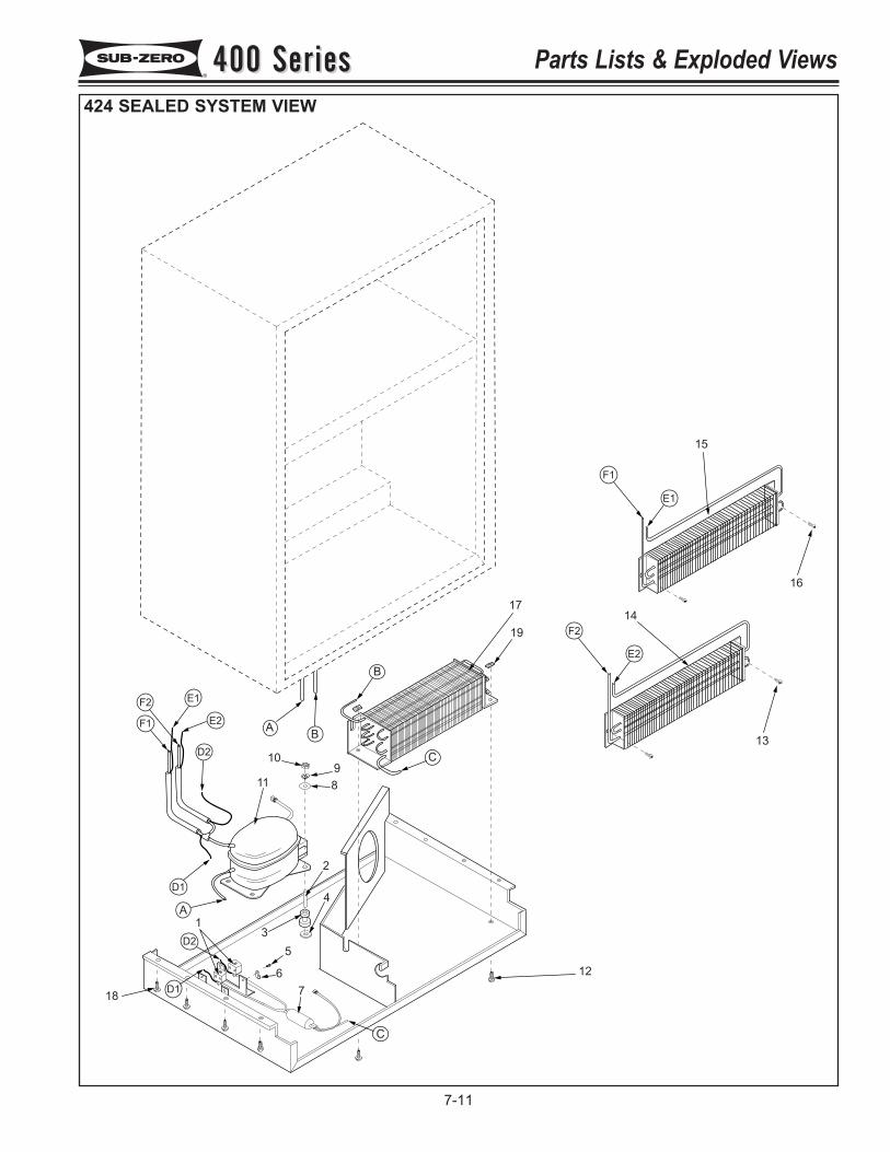
1
2
3
4
5
67
89
10
11
12
13
14
16
15
A B
B
C
C
D1
D1
A
D2
D2
E1
E2
E1
E2
F2
F1
F1
F2
17
19
18
400 Series400 Series Parts Lists & Exploded Views
7-11
424 SEALED SYSTEM VIEW
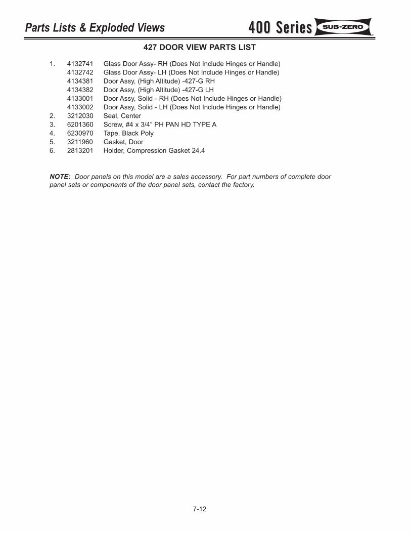
400 Series400 SeriesParts Lists & Exploded Views
7-12
427 DOOR VIEW PARTS LIST
1. 4132741 Glass Door Assy- RH (Does Not Include Hinges or Handle)4132742 Glass Door Assy- LH (Does Not Include Hinges or Handle)4134381 Door Assy, (High Altitude) -427-G RH4134382 Door Assy, (High Altitude) -427-G LH4133001 Door Assy, Solid - RH (Does Not Include Hinges or Handle)4133002 Door Assy, Solid - LH (Does Not Include Hinges or Handle)
2. 3212030 Seal, Center3. 6201360 Screw, #4 x 3/4” PH PAN HD TYPE A4. 6230970 Tape, Black Poly5. 3211960 Gasket, Door6. 2813201 Holder, Compression Gasket 24.4
NOTE: Door panels on this model are a sales accessory. For part numbers of complete doorpanel sets or components of the door panel sets, contact the factory.
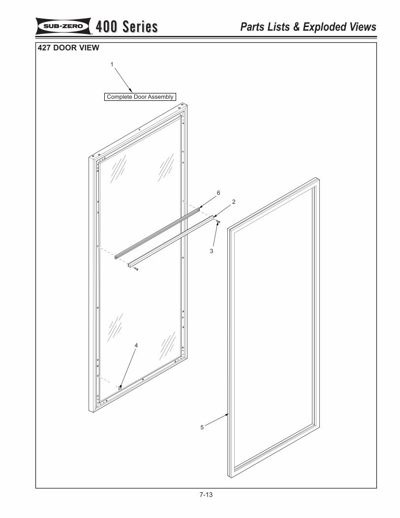
1
Complete Door Assembly
5
4
2
3
6
400 Series400 Series Parts Lists & Exploded Views
7-13
427 DOOR VIEW
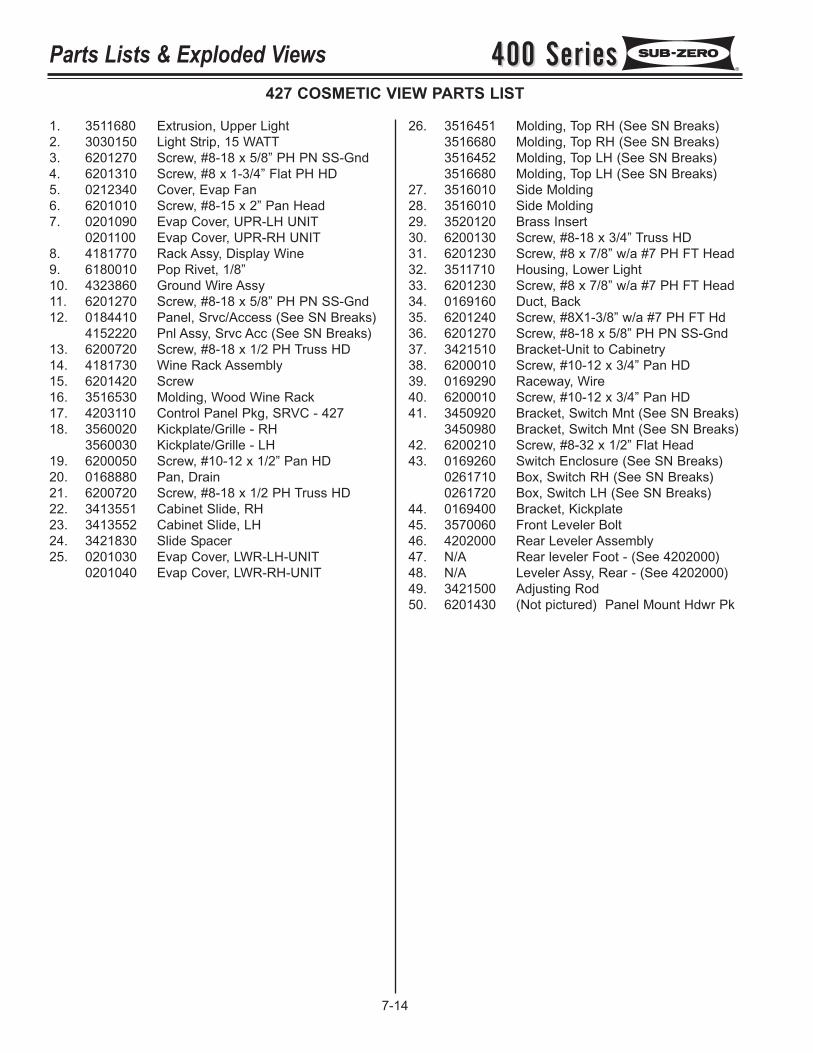
400 Series400 SeriesParts Lists & Exploded Views
7-14
427 COSMETIC VIEW PARTS LIST
1. 3511680 Extrusion, Upper Light2. 3030150 Light Strip, 15 WATT3. 6201270 Screw, #8-18 x 5/8” PH PN SS-Gnd4. 6201310 Screw, #8 x 1-3/4” Flat PH HD5. 0212340 Cover, Evap Fan6. 6201010 Screw, #8-15 x 2” Pan Head7. 0201090 Evap Cover, UPR-LH UNIT
0201100 Evap Cover, UPR-RH UNIT8. 4181770 Rack Assy, Display Wine9. 6180010 Pop Rivet, 1/8”10. 4323860 Ground Wire Assy11. 6201270 Screw, #8-18 x 5/8” PH PN SS-Gnd12. 0184410 Panel, Srvc/Access (See SN Breaks)
4152220 Pnl Assy, Srvc Acc (See SN Breaks)13. 6200720 Screw, #8-18 x 1/2 PH Truss HD14. 4181730 Wine Rack Assembly15. 6201420 Screw16. 3516530 Molding, Wood Wine Rack17. 4203110 Control Panel Pkg, SRVC - 42718. 3560020 Kickplate/Grille - RH
3560030 Kickplate/Grille - LH19. 6200050 Screw, #10-12 x 1/2” Pan HD20. 0168880 Pan, Drain21. 6200720 Screw, #8-18 x 1/2 PH Truss HD22. 3413551 Cabinet Slide, RH23. 3413552 Cabinet Slide, LH24. 3421830 Slide Spacer25. 0201030 Evap Cover, LWR-LH-UNIT
0201040 Evap Cover, LWR-RH-UNIT
26. 3516451 Molding, Top RH (See SN Breaks)3516680 Molding, Top RH (See SN Breaks)3516452 Molding, Top LH (See SN Breaks)3516680 Molding, Top LH (See SN Breaks)
27. 3516010 Side Molding28. 3516010 Side Molding29. 3520120 Brass Insert30. 6200130 Screw, #8-18 x 3/4” Truss HD31. 6201230 Screw, #8 x 7/8” w/a #7 PH FT Head32. 3511710 Housing, Lower Light33. 6201230 Screw, #8 x 7/8” w/a #7 PH FT Head34. 0169160 Duct, Back35. 6201240 Screw, #8X1-3/8” w/a #7 PH FT Hd36. 6201270 Screw, #8-18 x 5/8” PH PN SS-Gnd37. 3421510 Bracket-Unit to Cabinetry38. 6200010 Screw, #10-12 x 3/4” Pan HD39. 0169290 Raceway, Wire40. 6200010 Screw, #10-12 x 3/4” Pan HD41. 3450920 Bracket, Switch Mnt (See SN Breaks)
3450980 Bracket, Switch Mnt (See SN Breaks)42. 6200210 Screw, #8-32 x 1/2” Flat Head43. 0169260 Switch Enclosure (See SN Breaks)
0261710 Box, Switch RH (See SN Breaks)0261720 Box, Switch LH (See SN Breaks)
44. 0169400 Bracket, Kickplate45. 3570060 Front Leveler Bolt46. 4202000 Rear Leveler Assembly47. N/A Rear leveler Foot - (See 4202000)48. N/A Leveler Assy, Rear - (See 4202000)49. 3421500 Adjusting Rod50. 6201430 (Not pictured) Panel Mount Hdwr Pk
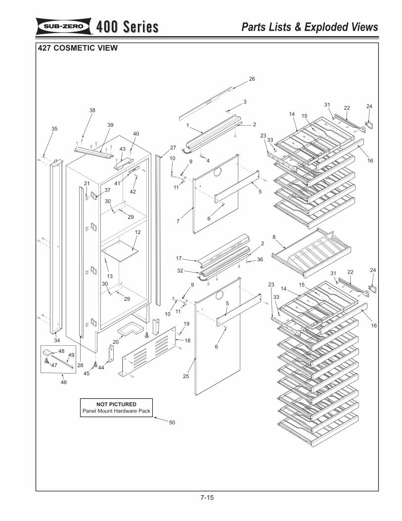
35
38
39
40
43 27
109
11
1
26
3
2
4
2333
14 15
3122 24
16
5
67
42
41
37
21
30
29
12
13
29
30
17
32
9
1011
2
36
8
5
23
33
1415
31 22 24
16
6
25
19
1820
28
34
45
44
4948
47
46
50
NOT PICTURED
Panel Mount Hardware Pack
400 Series400 Series Parts Lists & Exploded Views
7-15
427 COSMETIC VIEW
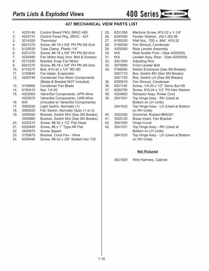
400 Series400 SeriesParts Lists & Exploded Views
7-16
427 MECHANICAL VIEW PARTS LIST
1. 4203140 Control Board PKG, SRVC 4002. 4203110 Control Panel Pkg, SRVC - 4273. 3014350 Thermistor4. 6201270 Screw, #8-18 x 5/8” PH PN SS-Gnd5. 6120030 Tube Clamp, Plastic 1/4”6. 6201270 Screw, #8-18 x 5/8” PH PN SS-Gnd7. 4220490 Fan Motor Assy (Incl. Brkt & Screws)8. 0212330 Bracket, Evap Fan Motor9. 6201270 Screw, #8-18 x 5/8” PH PN SS-Gnd10. 6110270 Bolt, #10-32 x 1/4” RD HD11. 3150640 Fan blade, Evaporator12. 4200740 Condenser Fan Motor Components
(Blade & Bracket NOT included)13. 3150660 Condenser Fan Blade14. 6150410 Nut, 1/4-2015. 4203060 Valve/Sol Components, UPR-Wine
4203070 Valve/Sol Components, LWR-Wine16. N/A (Included w/ Valve/Sol Components)17. 3060030 Light Switch, Normally (1)18. 3060020 Fan Switch, Normally Open (1 or 2)19. 3450920 Bracket, Switch Mnt (See SN Breaks)
3450980 Bracket, Switch Mnt (See SN Breaks)20. 6200210 Screw, #8-32 x 1/2” Flat Head21. 6200450 Screw, #8 x 1” Type AR Flat22. 3420670 Screw Spacer23. 3150670 Bracket, Cond Fan - Wine24. 6200490 Screw, #8-32 x 3/8” Slotted Hex T25
25. 6201280 Machine Screw, #10-32 x 1-1/4”26. 6240350 Fender Washer, .25x1.25x.0627. 6150330 Well Nut, .75D x .804”, #10-3228. 0169340 Fan Shroud, Condenser29. 4202000 Rear Leveler Assembly30. N/A Rear leveler Foot - (See 4202000)31. N/A Leveler Assy, Rear - (See 4202000)32. 3421500 Adjusting Rod33. 3570060 Front Leveler Bolt34. 0169260 Switch Enclosure (See SN Breaks)
0261710 Box, Switch RH (See SN Breaks)0261720 Box, Switch LH (See SN Breaks)
35. 6200010 Fan Shroud, Condenser36. 6201140 Screw, 1/4-20 x 1/2” Sems But HD37. 6200780 Screw, #10-24 x 1/2” PH Hex Washer38. 4324800 Retractor Assy, Power Cord39. 3541031 Top Hinge Assy - RH (Used at
Bottom on LH Units)3541032 Top Hinge Assy - LH (Used at Bottom
on RH Units)40. 3220250 Grommet, Rubber-#M535141. 3520120 Brass Insert, Fan Bracket42. 3541050 Hinge Cover43. 3541031 Top Hinge Assy - RH (Used at
Bottom on LH Units)3541032 Top Hinge Assy - LH (Used at Bottom
on RH Units)
Not Pictured
3021920 Wire Harness, Cabinet
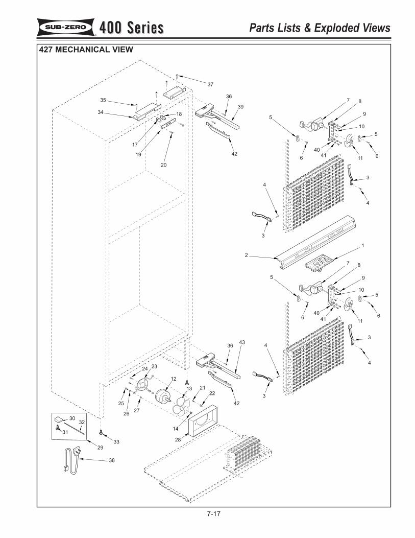
32
29
30
31
33
38
252726
14
28
24 23
12
13 2122
36 43
3
43
4
5
640
41 116
510
9
87
1
2
3
34
4
5
5
66 11
10
9
87
4041
39
36
37
20
19
17
34
35
42
42
18
400 Series400 Series Parts Lists & Exploded Views
7-17
427 MECHANICAL VIEW
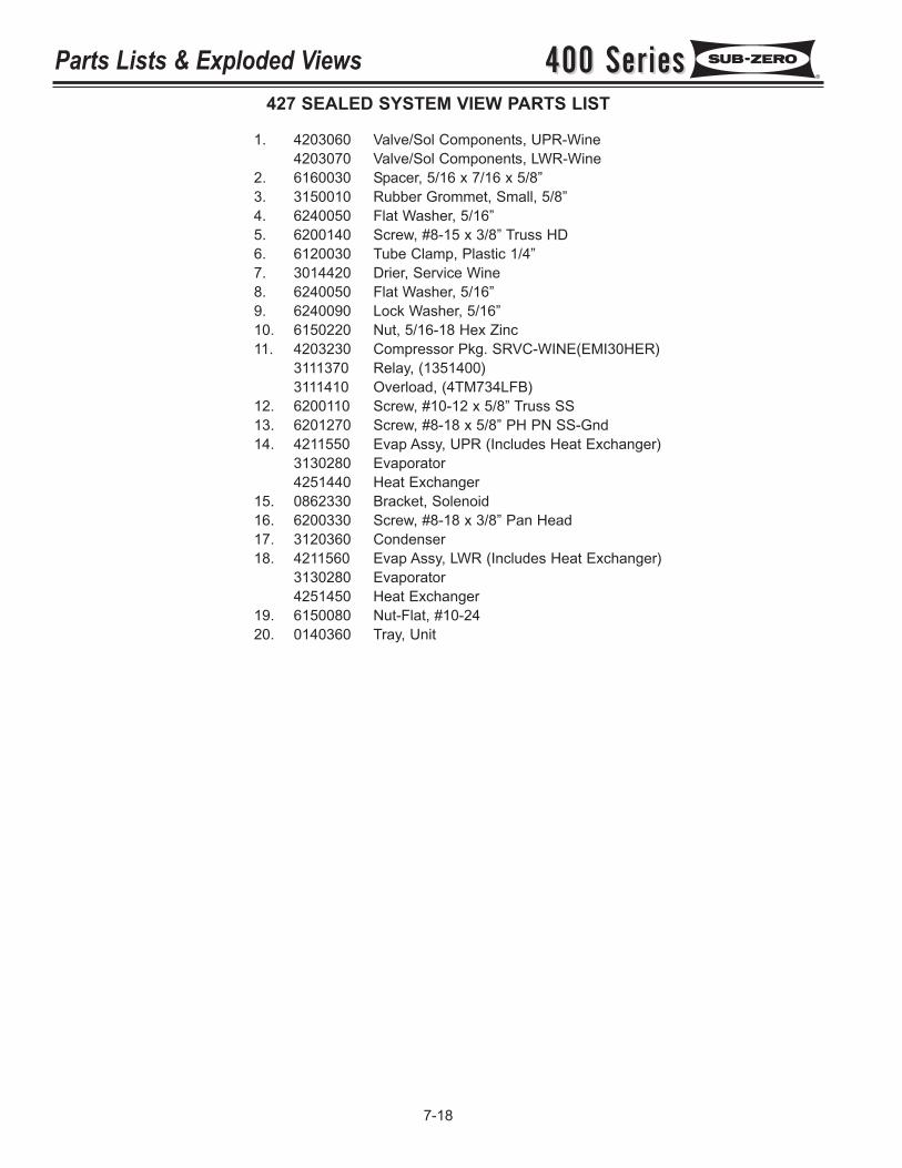
400 Series400 SeriesParts Lists & Exploded Views
7-18
427 SEALED SYSTEM VIEW PARTS LIST
1. 4203060 Valve/Sol Components, UPR-Wine4203070 Valve/Sol Components, LWR-Wine
2. 6160030 Spacer, 5/16 x 7/16 x 5/8”3. 3150010 Rubber Grommet, Small, 5/8”4. 6240050 Flat Washer, 5/16”5. 6200140 Screw, #8-15 x 3/8” Truss HD6. 6120030 Tube Clamp, Plastic 1/4”7. 3014420 Drier, Service Wine8. 6240050 Flat Washer, 5/16”9. 6240090 Lock Washer, 5/16”10. 6150220 Nut, 5/16-18 Hex Zinc11. 4203230 Compressor Pkg. SRVC-WINE(EMI30HER)
3111370 Relay, (1351400)3111410 Overload, (4TM734LFB)
12. 6200110 Screw, #10-12 x 5/8” Truss SS13. 6201270 Screw, #8-18 x 5/8” PH PN SS-Gnd14. 4211550 Evap Assy, UPR (Includes Heat Exchanger)
3130280 Evaporator4251440 Heat Exchanger
15. 0862330 Bracket, Solenoid16. 6200330 Screw, #8-18 x 3/8” Pan Head17. 3120360 Condenser18. 4211560 Evap Assy, LWR (Includes Heat Exchanger)
3130280 Evaporator4251450 Heat Exchanger
19. 6150080 Nut-Flat, #10-2420. 0140360 Tray, Unit
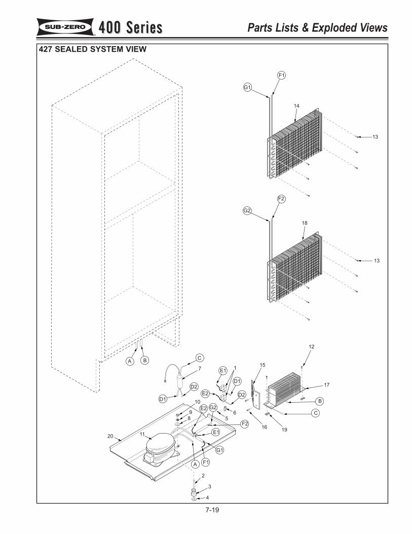
2
3
4
11
10
98
7 1
56
16
15
12
17
13
18
13
14
G1
F1
G2
F2
B
C
19F2
E1
G2E2
E2
G1
F1A
D2
D1
E1
D2
C
D1
20
A B
400 Series400 Series Parts Lists & Exploded Views
7-19
427 SEALED SYSTEM VIEW
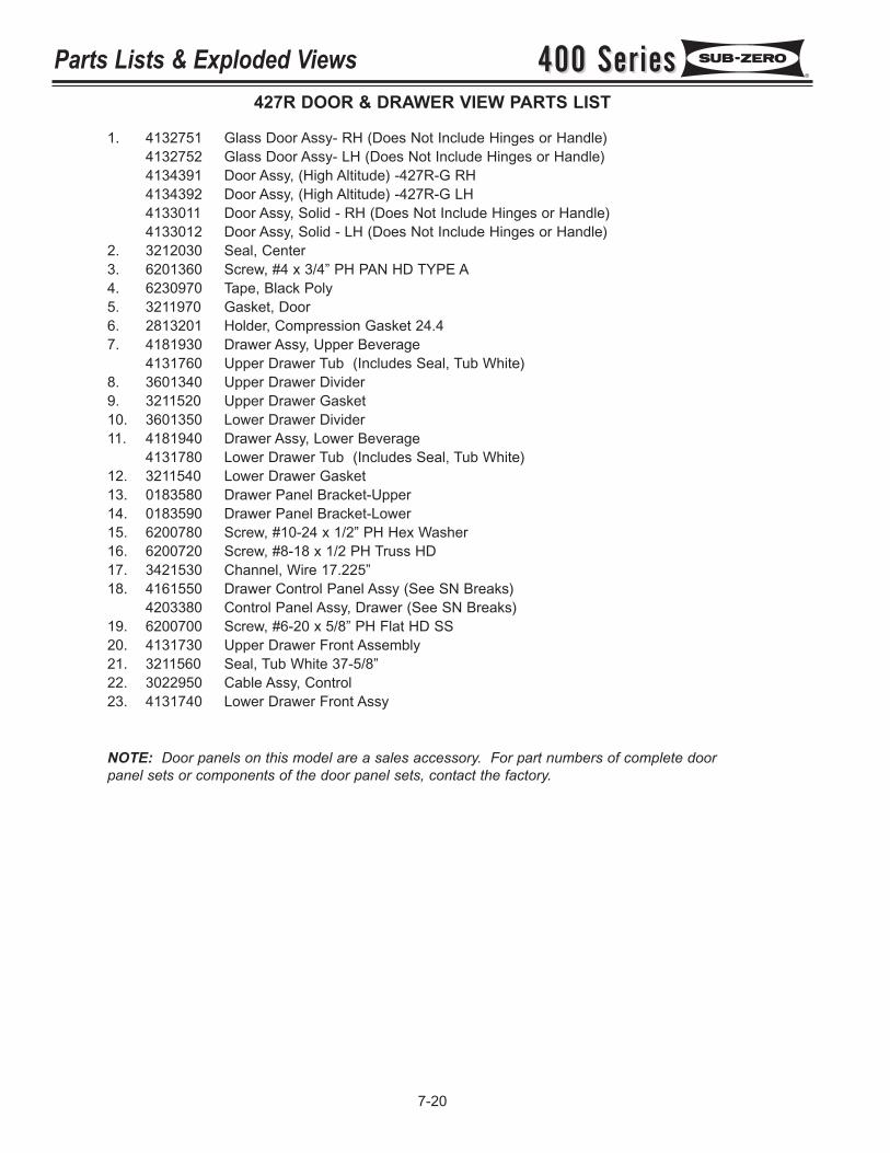
400 Series400 SeriesParts Lists & Exploded Views
7-20
427R DOOR & DRAWER VIEW PARTS LIST
1. 4132751 Glass Door Assy- RH (Does Not Include Hinges or Handle)4132752 Glass Door Assy- LH (Does Not Include Hinges or Handle)4134391 Door Assy, (High Altitude) -427R-G RH4134392 Door Assy, (High Altitude) -427R-G LH4133011 Door Assy, Solid - RH (Does Not Include Hinges or Handle)4133012 Door Assy, Solid - LH (Does Not Include Hinges or Handle)
2. 3212030 Seal, Center3. 6201360 Screw, #4 x 3/4” PH PAN HD TYPE A4. 6230970 Tape, Black Poly5. 3211970 Gasket, Door6. 2813201 Holder, Compression Gasket 24.47. 4181930 Drawer Assy, Upper Beverage
4131760 Upper Drawer Tub (Includes Seal, Tub White)8. 3601340 Upper Drawer Divider9. 3211520 Upper Drawer Gasket10. 3601350 Lower Drawer Divider11. 4181940 Drawer Assy, Lower Beverage
4131780 Lower Drawer Tub (Includes Seal, Tub White)12. 3211540 Lower Drawer Gasket13. 0183580 Drawer Panel Bracket-Upper14. 0183590 Drawer Panel Bracket-Lower15. 6200780 Screw, #10-24 x 1/2” PH Hex Washer16. 6200720 Screw, #8-18 x 1/2 PH Truss HD17. 3421530 Channel, Wire 17.225”18. 4161550 Drawer Control Panel Assy (See SN Breaks)
4203380 Control Panel Assy, Drawer (See SN Breaks)19. 6200700 Screw, #6-20 x 5/8” PH Flat HD SS20. 4131730 Upper Drawer Front Assembly21. 3211560 Seal, Tub White 37-5/8”22. 3022950 Cable Assy, Control23. 4131740 Lower Drawer Front Assy
NOTE: Door panels on this model are a sales accessory. For part numbers of complete doorpanel sets or components of the door panel sets, contact the factory.
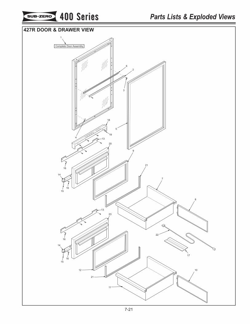
2
3
5
4
6
1
Complete Door Assembly
7
8
17
18
20
1913
9
15
14
16
1621
11
10
23
15
14
16
21
12
13
16
22
400 Series400 Series Parts Lists & Exploded Views
7-21
427R DOOR & DRAWER VIEW
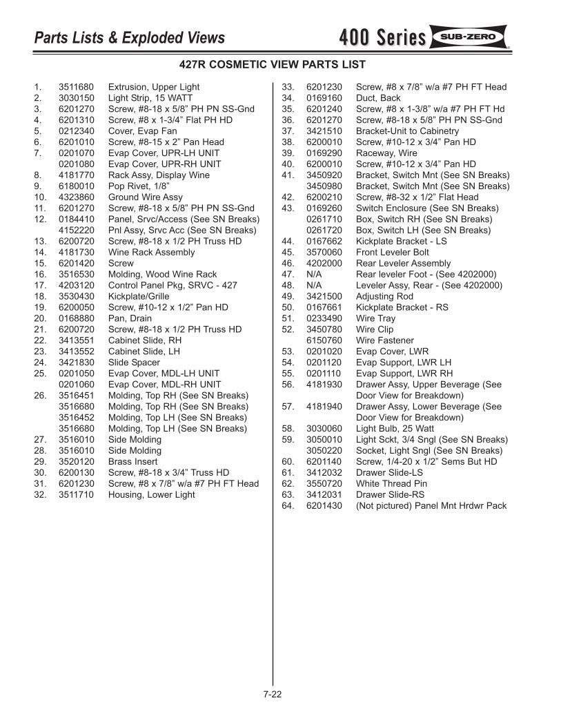
400 Series400 SeriesParts Lists & Exploded Views
7-22
427R COSMETIC VIEW PARTS LIST
1. 3511680 Extrusion, Upper Light2. 3030150 Light Strip, 15 WATT3. 6201270 Screw, #8-18 x 5/8” PH PN SS-Gnd4. 6201310 Screw, #8 x 1-3/4” Flat PH HD5. 0212340 Cover, Evap Fan6. 6201010 Screw, #8-15 x 2” Pan Head7. 0201070 Evap Cover, UPR-LH UNIT
0201080 Evap Cover, UPR-RH UNIT8. 4181770 Rack Assy, Display Wine9. 6180010 Pop Rivet, 1/8”10. 4323860 Ground Wire Assy11. 6201270 Screw, #8-18 x 5/8” PH PN SS-Gnd12. 0184410 Panel, Srvc/Access (See SN Breaks)
4152220 Pnl Assy, Srvc Acc (See SN Breaks)13. 6200720 Screw, #8-18 x 1/2 PH Truss HD14. 4181730 Wine Rack Assembly15. 6201420 Screw16. 3516530 Molding, Wood Wine Rack17. 4203120 Control Panel Pkg, SRVC - 42718. 3530430 Kickplate/Grille19. 6200050 Screw, #10-12 x 1/2” Pan HD20. 0168880 Pan, Drain21. 6200720 Screw, #8-18 x 1/2 PH Truss HD22. 3413551 Cabinet Slide, RH23. 3413552 Cabinet Slide, LH24. 3421830 Slide Spacer25. 0201050 Evap Cover, MDL-LH UNIT
0201060 Evap Cover, MDL-RH UNIT26. 3516451 Molding, Top RH (See SN Breaks)
3516680 Molding, Top RH (See SN Breaks)3516452 Molding, Top LH (See SN Breaks)3516680 Molding, Top LH (See SN Breaks)
27. 3516010 Side Molding28. 3516010 Side Molding29. 3520120 Brass Insert30. 6200130 Screw, #8-18 x 3/4” Truss HD31. 6201230 Screw, #8 x 7/8” w/a #7 PH FT Head32. 3511710 Housing, Lower Light
33. 6201230 Screw, #8 x 7/8” w/a #7 PH FT Head34. 0169160 Duct, Back35. 6201240 Screw, #8 x 1-3/8” w/a #7 PH FT Hd36. 6201270 Screw, #8-18 x 5/8” PH PN SS-Gnd37. 3421510 Bracket-Unit to Cabinetry38. 6200010 Screw, #10-12 x 3/4” Pan HD39. 0169290 Raceway, Wire40. 6200010 Screw, #10-12 x 3/4” Pan HD41. 3450920 Bracket, Switch Mnt (See SN Breaks)
3450980 Bracket, Switch Mnt (See SN Breaks)42. 6200210 Screw, #8-32 x 1/2” Flat Head43. 0169260 Switch Enclosure (See SN Breaks)
0261710 Box, Switch RH (See SN Breaks)0261720 Box, Switch LH (See SN Breaks)
44. 0167662 Kickplate Bracket - LS45. 3570060 Front Leveler Bolt46. 4202000 Rear Leveler Assembly47. N/A Rear leveler Foot - (See 4202000)48. N/A Leveler Assy, Rear - (See 4202000)49. 3421500 Adjusting Rod50. 0167661 Kickplate Bracket - RS51. 0233490 Wire Tray52. 3450780 Wire Clip
6150760 Wire Fastener53. 0201020 Evap Cover, LWR54. 0201120 Evap Support, LWR LH55. 0201110 Evap Support, LWR RH56. 4181930 Drawer Assy, Upper Beverage (See
Door View for Breakdown)57. 4181940 Drawer Assy, Lower Beverage (See
Door View for Breakdown)58. 3030060 Light Bulb, 25 Watt59. 3050010 Light Sckt, 3/4 Sngl (See SN Breaks)
3050220 Socket, Light Sngl (See SN Breaks)60. 6201140 Screw, 1/4-20 x 1/2” Sems But HD61. 3412032 Drawer Slide-LS62. 3550720 White Thread Pin63. 3412031 Drawer Slide-RS64. 6201430 (Not pictured) Panel Mnt Hrdwr Pack
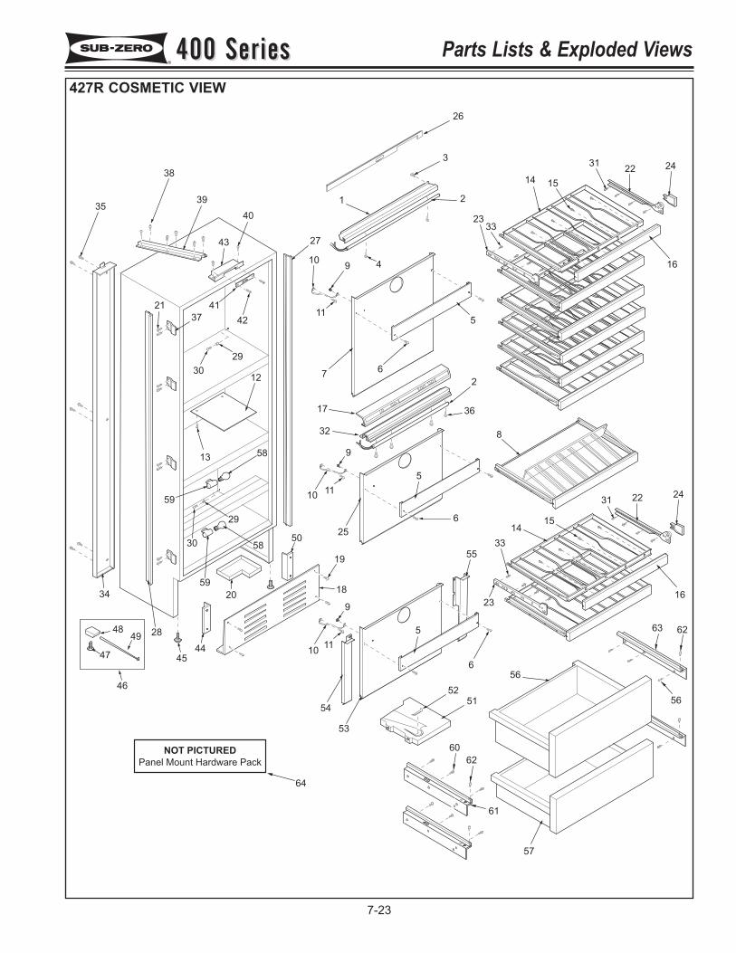
35
38
39
40
27
109
11
1
26
3
2
4
2333
14 15
3122 24
16
5
67
42
41
37
30
29
12
13
29
5830
10
10
17
32
2
36
8
23
33
1415
31 22 24
16
9
11
5
6
25
19
1820
28
34
43
21
52
51
56
57
45
44
50
59
58
59
9
11
5
6
53
55
54
60
62
61
56
63 6249
48
47
46
64
NOT PICTURED
Panel Mount Hardware Pack
400 Series400 Series Parts Lists & Exploded Views
7-23
427R COSMETIC VIEW
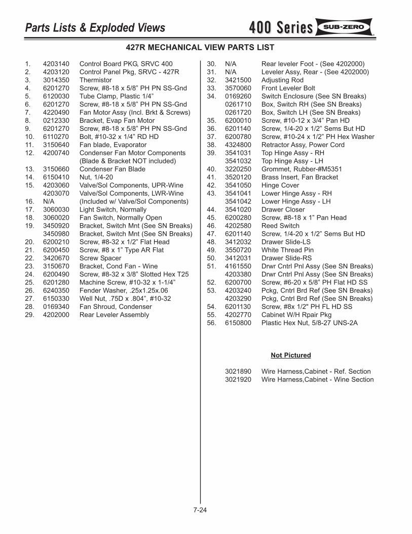
400 Series400 SeriesParts Lists & Exploded Views
7-24
427R MECHANICAL VIEW PARTS LIST
1. 4203140 Control Board PKG, SRVC 4002. 4203120 Control Panel Pkg, SRVC - 427R3. 3014350 Thermistor4. 6201270 Screw, #8-18 x 5/8” PH PN SS-Gnd5. 6120030 Tube Clamp, Plastic 1/4”6. 6201270 Screw, #8-18 x 5/8” PH PN SS-Gnd7. 4220490 Fan Motor Assy (Incl. Brkt & Screws)8. 0212330 Bracket, Evap Fan Motor9. 6201270 Screw, #8-18 x 5/8” PH PN SS-Gnd10. 6110270 Bolt, #10-32 x 1/4” RD HD11. 3150640 Fan blade, Evaporator12. 4200740 Condenser Fan Motor Components
(Blade & Bracket NOT included)13. 3150660 Condenser Fan Blade14. 6150410 Nut, 1/4-2015. 4203060 Valve/Sol Components, UPR-Wine
4203070 Valve/Sol Components, LWR-Wine16. N/A (Included w/ Valve/Sol Components)17. 3060030 Light Switch, Normally18. 3060020 Fan Switch, Normally Open19. 3450920 Bracket, Switch Mnt (See SN Breaks)
3450980 Bracket, Switch Mnt (See SN Breaks)20. 6200210 Screw, #8-32 x 1/2” Flat Head21. 6200450 Screw, #8 x 1” Type AR Flat22. 3420670 Screw Spacer23. 3150670 Bracket, Cond Fan - Wine24. 6200490 Screw, #8-32 x 3/8” Slotted Hex T2525. 6201280 Machine Screw, #10-32 x 1-1/4”26. 6240350 Fender Washer, .25x1.25x.0627. 6150330 Well Nut, .75D x .804”, #10-3228. 0169340 Fan Shroud, Condenser29. 4202000 Rear Leveler Assembly
30. N/A Rear leveler Foot - (See 4202000)31. N/A Leveler Assy, Rear - (See 4202000)32. 3421500 Adjusting Rod33. 3570060 Front Leveler Bolt34. 0169260 Switch Enclosure (See SN Breaks)
0261710 Box, Switch RH (See SN Breaks)0261720 Box, Switch LH (See SN Breaks)
35. 6200010 Screw, #10-12 x 3/4” Pan HD36. 6201140 Screw, 1/4-20 x 1/2” Sems But HD37. 6200780 Screw, #10-24 x 1/2” PH Hex Washer38. 4324800 Retractor Assy, Power Cord39. 3541031 Top Hinge Assy - RH
3541032 Top Hinge Assy - LH40. 3220250 Grommet, Rubber-#M535141. 3520120 Brass Insert, Fan Bracket42. 3541050 Hinge Cover43. 3541041 Lower Hinge Assy - RH
3541042 Lower Hinge Assy - LH44. 3541020 Drawer Closer45. 6200280 Screw, #8-18 x 1” Pan Head46. 4202580 Reed Switch47. 6201140 Screw, 1/4-20 x 1/2” Sems But HD48. 3412032 Drawer Slide-LS49. 3550720 White Thread Pin50. 3412031 Drawer Slide-RS51. 4161550 Drwr Cntrl Pnl Assy (See SN Breaks)
4203380 Drwr Cntrl Pnl Assy (See SN Breaks)52. 6200700 Screw, #6-20 x 5/8” PH Flat HD SS53. 4203240 Pckg, Cntrl Brd Ref (See SN Breaks)
4203290 Pckg, Cntrl Brd Ref (See SN Breaks)54. 6201130 Screw, #8x 1/2" PH FL HD SS55. 4202770 Cabinet W/H Rpair Pkg56. 6150800 Plastic Hex Nut, 5/8-27 UNS-2A
Not Pictured
3021890 Wire Harness,Cabinet - Ref. Section3021920 Wire Harness,Cabinet - Wine Section
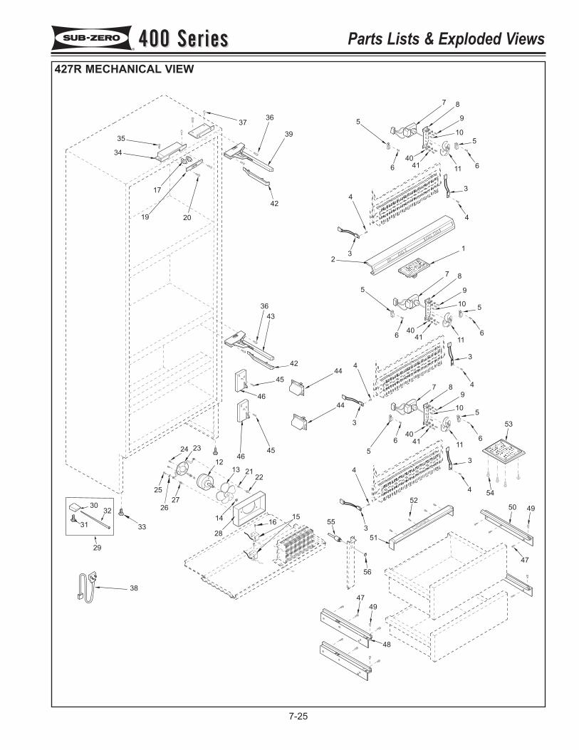
33
38
47
49
48
50 49
47
51
3
4
4
3
52
5
640
4111
6
510
9
87
3
4
4
3
11
66
5
5
40
41
10
9
87
1
4
4
3
32
1166
5
5
40
41
10
9
87
39
42
3736
35
34
17
19 20
42
45
46
4645
44
44
43
36
12
13 2122
28
14
27
25
24 23
26
1615
3230
31
29
53
54
55
56
400 Series400 Series Parts Lists & Exploded Views
7-25
427R MECHANICAL VIEW
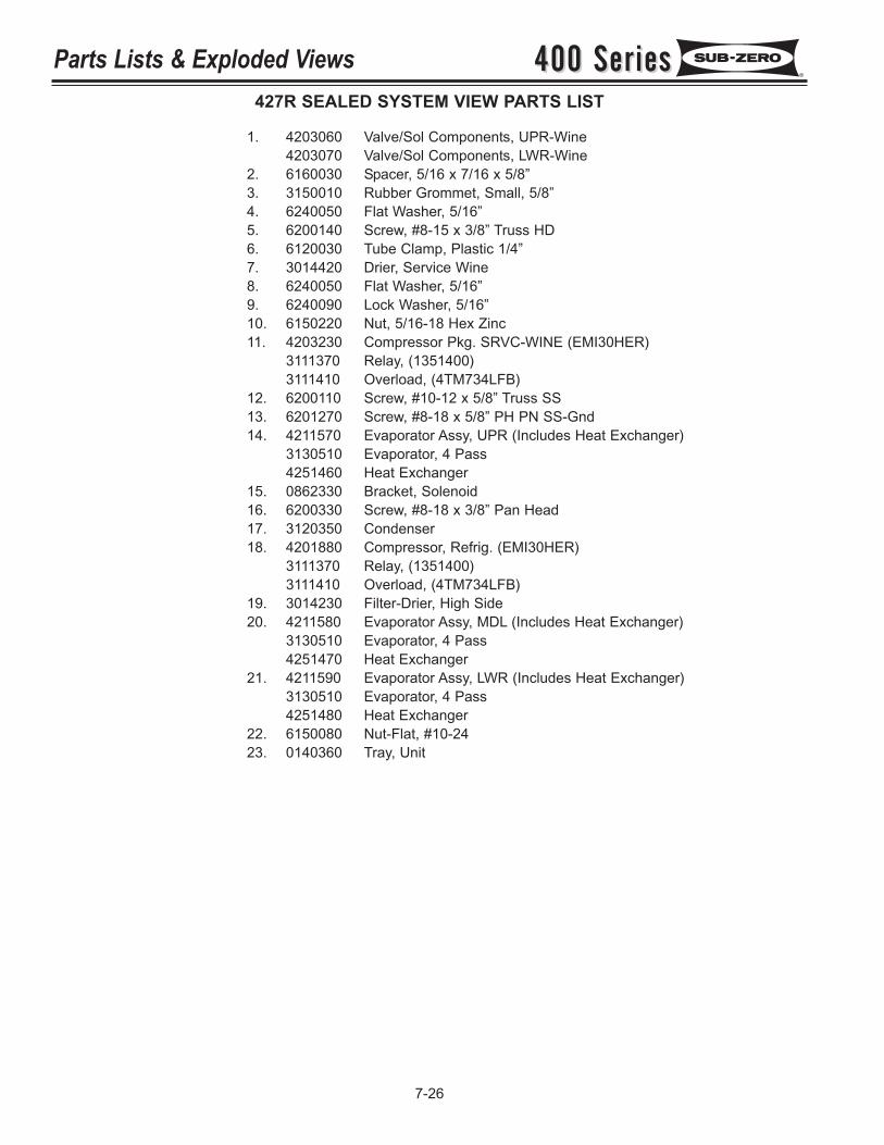
400 Series400 SeriesParts Lists & Exploded Views
7-26
427R SEALED SYSTEM VIEW PARTS LIST
1. 4203060 Valve/Sol Components, UPR-Wine4203070 Valve/Sol Components, LWR-Wine
2. 6160030 Spacer, 5/16 x 7/16 x 5/8”3. 3150010 Rubber Grommet, Small, 5/8”4. 6240050 Flat Washer, 5/16”5. 6200140 Screw, #8-15 x 3/8” Truss HD6. 6120030 Tube Clamp, Plastic 1/4”7. 3014420 Drier, Service Wine8. 6240050 Flat Washer, 5/16”9. 6240090 Lock Washer, 5/16”10. 6150220 Nut, 5/16-18 Hex Zinc11. 4203230 Compressor Pkg. SRVC-WINE (EMI30HER)
3111370 Relay, (1351400)3111410 Overload, (4TM734LFB)
12. 6200110 Screw, #10-12 x 5/8” Truss SS13. 6201270 Screw, #8-18 x 5/8” PH PN SS-Gnd14. 4211570 Evaporator Assy, UPR (Includes Heat Exchanger)
3130510 Evaporator, 4 Pass4251460 Heat Exchanger
15. 0862330 Bracket, Solenoid16. 6200330 Screw, #8-18 x 3/8” Pan Head17. 3120350 Condenser18. 4201880 Compressor, Refrig. (EMI30HER)
3111370 Relay, (1351400)3111410 Overload, (4TM734LFB)
19. 3014230 Filter-Drier, High Side20. 4211580 Evaporator Assy, MDL (Includes Heat Exchanger)
3130510 Evaporator, 4 Pass4251470 Heat Exchanger
21. 4211590 Evaporator Assy, LWR (Includes Heat Exchanger)3130510 Evaporator, 4 Pass4251480 Heat Exchanger
22. 6150080 Nut-Flat, #10-2423. 0140360 Tray, Unit
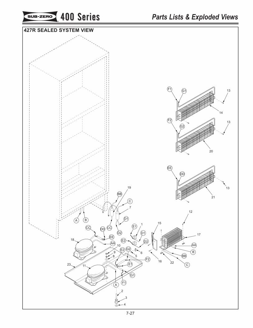
2
3
4
11
18
10
98
16
151
65
7
19
12
17
21
13
20
14
13
13F1 G1
F2
G2
EE
DD
AA
BBB
C
F1
G1
E1F2
E2 G2
D2
D1
E1
E2
BB
C
D1
D2CC
EE
AA
A
23
CC DD
A B
22
400 Series400 Series Parts Lists & Exploded Views
7-27
427R SEALED SYSTEM VIEW
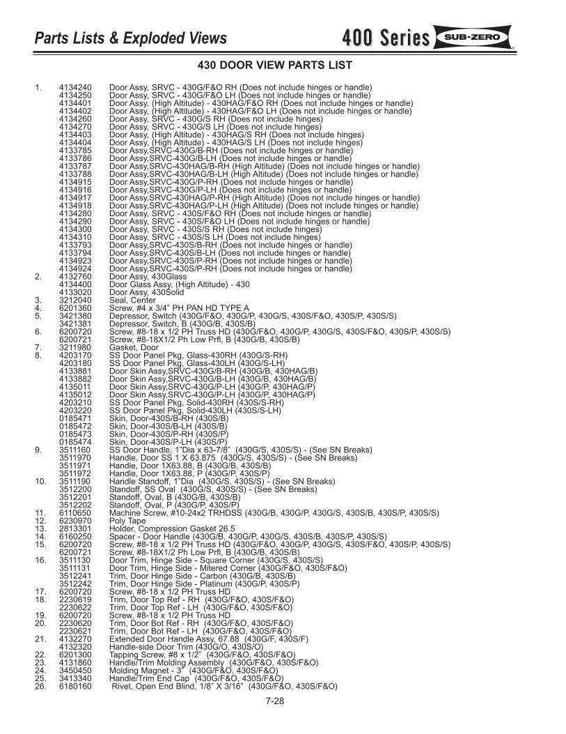
400 Series400 SeriesParts Lists & Exploded Views
7-28
430 DOOR VIEW PARTS LIST
1. 4134240 Door Assy, SRVC - 430G/F&O RH (Does not include hinges or handle)4134250 Door Assy, SRVC - 430G/F&O LH (Does not include hinges or handle)4134401 Door Assy, (High Altitude) - 430HAG/F&O RH (Does not include hinges or handle)4134402 Door Assy, (High Altitude) - 430HAG/F&O LH (Does not include hinges or handle)4134260 Door Assy, SRVC - 430G/S RH (Does not include hinges)4134270 Door Assy, SRVC - 430G/S LH (Does not include hinges)4134403 Door Assy, (High Altitude) - 430HAG/S RH (Does not include hinges)4134404 Door Assy, (High Altitude) - 430HAG/S LH (Does not include hinges)4133785 Door Assy,SRVC-430G/B-RH (Does not include hinges or handle)4133786 Door Assy,SRVC-430G/B-LH (Does not include hinges or handle)4133787 Door Assy,SRVC-430HAG/B-RH (High Altitude) (Does not include hinges or handle)4133788 Door Assy,SRVC-430HAG/B-LH (High Altitude) (Does not include hinges or handle)4134915 Door Assy,SRVC-430G/P-RH (Does not include hinges or handle)4134916 Door Assy,SRVC-430G/P-LH (Does not include hinges or handle)4134917 Door Assy,SRVC-430HAG/P-RH (High Altitude) (Does not include hinges or handle)4134918 Door Assy,SRVC-430HAG/P-LH (High Altitude) (Does not include hinges or handle)4134280 Door Assy, SRVC - 430S/F&O RH (Does not include hinges or handle)4134290 Door Assy, SRVC - 430S/F&O LH (Does not include hinges or handle)4134300 Door Assy, SRVC - 430S/S RH (Does not include hinges)4134310 Door Assy, SRVC - 430S/S LH (Does not include hinges)4133793 Door Assy,SRVC-430S/B-RH (Does not include hinges or handle)4133794 Door Assy,SRVC-430S/B-LH (Does not include hinges or handle)4134923 Door Assy,SRVC-430S/P-RH (Does not include hinges or handle)4134924 Door Assy,SRVC-430S/P-RH (Does not include hinges or handle)
2. 4132760 Door Assy, 430Glass4134400 Door Glass Assy, (High Altitude) - 4304133020 Door Assy, 430Solid
3. 3212040 Seal, Center4. 6201360 Screw, #4 x 3/4” PH PAN HD TYPE A5. 3421380 Depressor, Switch (430G/F&O, 430G/P, 430G/S, 430S/F&O, 430S/P, 430S/S)
3421381 Depressor, Switch, B (430G/B, 430S/B)6. 6200720 Screw, #8-18 x 1/2 PH Truss HD (430G/F&O, 430G/P, 430G/S, 430S/F&O, 430S/P, 430S/S)
6200721 Screw, #8-18X1/2 Ph Low Prfl, B (430G/B, 430S/B)7. 3211980 Gasket, Door8. 4203170 SS Door Panel Pkg, Glass-430RH (430G/S-RH)
4203180 SS Door Panel Pkg, Glass-430LH (430G/S-LH)4133881 Door Skin Assy,SRVC-430G/B-RH (430G/B, 430HAG/B)4133882 Door Skin Assy,SRVC-430G/B-LH (430G/B, 430HAG/B)4135011 Door Skin Assy,SRVC-430G/P-LH (430G/P, 430HAG/P)4135012 Door Skin Assy,SRVC-430G/P-LH (430G/P, 430HAG/P)4203210 SS Door Panel Pkg, Solid-430RH (430S/S-RH)4203220 SS Door Panel Pkg, Solid-430LH (430S/S-LH)0185471 Skin, Door-430S/B-RH (430S/B)0185472 Skin, Door-430S/B-LH (430S/B)0185473 Skin, Door-430S/P-RH (430S/P)0185474 Skin, Door-430S/P-LH (430S/P)
9. 3511160 SS Door Handle, 1”Dia x 63-7/8” (430G/S, 430S/S) - (See SN Breaks)3511970 Handle, Door SS 1 X 63.875 (430G/S, 430S/S) - (See SN Breaks)3511971 Handle, Door 1X63.88, B (430G/B, 430S/B)3511972 Handle, Door 1X63.88, P (430G/P, 430S/P)
10. 3511190 Handle Standoff, 1”Dia (430G/S, 430S/S) - (See SN Breaks)3512200 Standoff, SS Oval (430G/S, 430S/S) - (See SN Breaks)3512201 Standoff, Oval, B (430G/B, 430S/B)3512202 Standoff, Oval, P (430G/P, 430S/P)
11. 6110650 Machine Screw, #10-24x2 TRHDSS (430G/B, 430G/P, 430G/S, 430S/B, 430S/P, 430S/S)12. 6230970 Poly Tape13. 2813301 Holder, Compression Gasket 26.514. 6160250 Spacer - Door Handle (430G/B, 430G/P, 430G/S, 430S/B, 430S/P, 430S/S)15. 6200720 Screw, #8-18 x 1/2 PH Truss HD (430G/F&O, 430G/P, 430G/S, 430S/F&O, 430S/P, 430S/S)
6200721 Screw, #8-18X1/2 Ph Low Prfl, B (430G/B, 430S/B)16. 3511130 Door Trim, Hinge Side - Square Corner (430G/S, 430S/S)
3511131 Door Trim, Hinge Side - Mitered Corner (430G/F&O, 430S/F&O)3512241 Trim, Door Hinge Side - Carbon (430G/B, 430S/B)3512242 Trim, Door Hinge Side - Platinum (430G/P, 430S/P)
17. 6200720 Screw, #8-18 x 1/2 PH Truss HD18. 2230619 Trim, Door Top Ref - RH (430G/F&O, 430S/F&O)
2230622 Trim, Door Top Ref - LH (430G/F&O, 430S/F&O)19. 6200720 Screw, #8-18 x 1/2 PH Truss HD20. 2230620 Trim, Door Bot Ref - RH (430G/F&O, 430S/F&O)
2230621 Trim, Door Bot Ref - LH (430G/F&O, 430S/F&O)21. 4132270 Extended Door Handle Assy, 67.88 (430G/F, 430S/F)
4132320 Handle-side Door Trim (430G/O, 430S/O)22. 6201300 Tapping Screw, #8 x 1/2” (430G/F&O, 430S/F&O)23. 4131860 Handle/Trim Molding Assembly (430G/F&O, 430S/F&O)24. 3450450 Molding Magnet - 3” (430G/F&O, 430S/F&O)25. 3413340 Handle/Trim End Cap (430G/F&O, 430S/F&O)26. 6180160 Rivet, Open End Blind, 1/8” X 3/16” (430G/F&O, 430S/F&O)
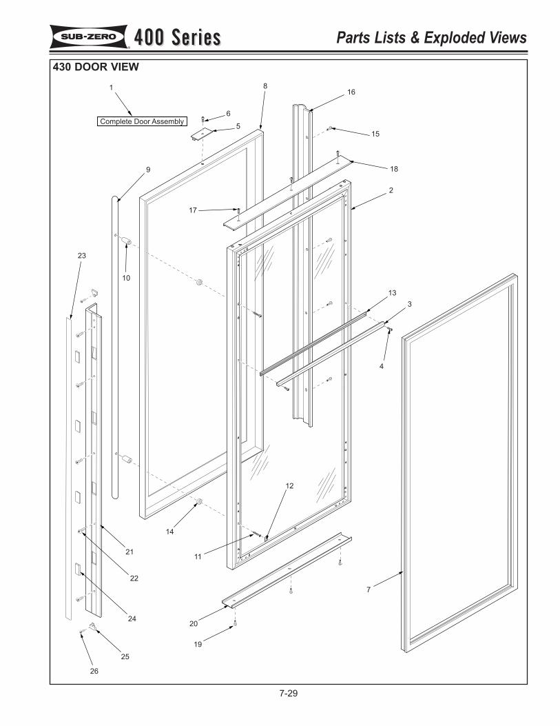
1
Complete Door Assembly
2
7
8
9
10
11
12
5
6
16
15
3
4
13
18
17
23
14
21
22
24
25
26
19
20
400 Series400 Series Parts Lists & Exploded Views
7-29
430 DOOR VIEW
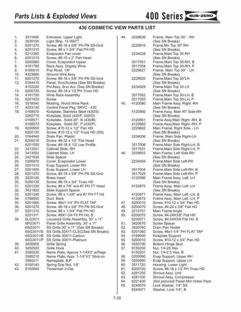
400 Series400 SeriesParts Lists & Exploded Views
7-30
430 COSMETIC VIEW PARTS LIST
1. 3511690 Extrusion, Upper Light2. 3030150 Light Strip, 15 WATT3. 6201270 Screw, #8-18 x 5/8” PH PN SS-Gnd4. 6201310 Screw, #8 x 1-3/4” Flat PH HD5. 0212360 Evaporator Fan cover6. 6201010 Screw, #8-15 x 2” Pan Head7. 0200960 Cover, Evaporator Upper8. 4181780 Rack Assy, Display Wine9. 6180010 Pop Rivet, 1/8”10. 4323860 Ground Wire Assy11. 6201270 Screw, #8-18 x 5/8” PH PN SS-Gnd12. 0184410 Panel, Srvc/Access (See SN Breaks)
4152220 Pnl Assy, Srvc Acc (See SN Breaks)13. 6200720 Screw, #8-18 x 1/2 PH Truss HD14. 4181750 Wine Rack Assembly15. 6201420 Screw16. 3516540 Molding, Wood Wine Rack17. 4203130 Control Panel Pkg, SRVC - 43018. 0168570 Kickplate, Stainless Steel (430/S)
0260710 Kickplate, Solid (430/F, 430/O)0168571 Kickplate, Solid-30", B (430/B)0168572 Kickplate, Solid-30", P (430/P)
19. 6200050 Screw, #10-12 x 1/2” Pan HD6200120 Screw, #10-12 x 1/2" Truss HD (SS)
20. 0164940 Drain Pan, Plastic21. 6200210 Screw, #8-32 x 1/2” Flat Head
6201550 Screw, #8-18 X 1/2 Low Profile22. 3413551 Cabinet Slide, RH23. 3413552 Cabinet Slide, LH24. 3421830 Slide Spacer25. 0200970 Cover, Evaporator Lower26. 0201010 Evap Support, Lower RH27. 0201000 Evap Support, Lower LH28. 6201270 Screw, #8-18 x 5/8” PH PN SS-Gnd29. 3520120 Brass Insert30. 6200130 Screw, #8-18 x 3/4” Truss HD31. 6201230 Screw, #8 x 7/8” w/a #7 PH FT Head32. 3421820 Slide Support Spacer33. 6201240 Screw, #8 x 1-3/8” w/a #7 PH FT Hd34. 0168950 Duct, Back35. 6201060 Screw, #8x1-1/4” PH FLAT TAP36. 6201270 Screw, #8-18 x 5/8” PH PN SS-Gnd37. 6201310 Screw, #8 x 1-3/4” Flat PH HD
6201311 Screw, #8X1-3/4 Flt Ph Hd, B38. 6LG3011 Louvered Grille Assembly, 30” x 11”
6PG3011 Panel Grille Assembly, 30” x 11”6SG3011 SS Grille 30” x 11” (See SN Breaks)6SG3011/S SS Grille,30X11-CLSC(See SN Breaks)6SG3011/B SS Grille 30X11-Carbon6SG3011/P SS Grille 30X11-Platinum
39. 3450900 Grille Spring40. 3450520 Grille Hook41. 3580230 Name Plate, Approx 1-1/4X3” w/Pegs
3580210 Name Plate, Appr. 1-1/4”X3” Stick-on3580211 Nameplate, B,P
42. 6150140 Spring Grip Nut, 1/8”43. 6150840 Tinnerman J-Clip
44. 2229626 Frame, Main Top 30” - RH (See SN Breaks)
2229910 Frame,Mn Top 30" RH (See SN Breaks)
2234028 Frame,Main Top 30 RH (See SN Breaks)
3517051 Frame,Main Top 30-RH, B3517054 Frame,Main Top 30-RH, P2229627 Frame, Main Top 30” - LH
(See SN Breaks)2229920 Frame,Main Top 30"LH
(See SN Breaks)2234029 Frame,Main Top 30 LH
(See SN Breaks)3517052 Frame,Main Top 30-LH, B3517055 Frame,Main Top 30-LH, P
45. 4120580 Main Frame Assy, Right -RH (See SN Breaks)
4120860 Frame Assy, Main RT Side-RH (See SN Breaks)
4120861 Frame Assy,Main Right -RH, B4120862 Frame Assy,Main Right -RH, P2229602 Main Frame, Right Side - LH
(See SN Breaks)2234006 Frame, Main Side Right-LH
(See SN Breaks)3517006 Frame,Main Side Right-LH, B 3517031 Frame,Main Side Right-LH, P
46. 2229603 Main Frame, Left Side-RH (See SN Breaks)
2234004 Frame,Main Side Left-RH (See SN Breaks)
3517004 Frame,Main Side Left-RH, B3517029 Frame,Main Side Left-RH, P4120590 Main Frame Assy, Left -LH
(See SN Breaks)4120870 Frame Assy, Main Left -LH
(See SN Breaks)4120871 Frame Assy, Main Left -LH, B4120872 Frame Assy, Main Left -LH, P
47. 6200010 Screw, #10-12 x 3/4” Pan HD48. 6200070 Screw, #4-24 x 3/8” Flat HD49. 2210701 Main Frame Angle50. 6200070 Screw, #4-24X3/8” Flat HD
6200071 Screw, #4-24X3/8 Flat Hd, B51. 3420670 Screw Spacer52. 3420760 Drain Pan Holder53. 6201060 Screw, #8x1-1/4” PH FLAT TAP54. 0169050 Kickplate Support55. 6200010 Screw, #10-12 x 3/4” Pan HD56. 3550190 Bottom Hinge Stud57. 6150200 Nut, 1/4-20 Hex
6150201 Nut, 1/4-2 0 Hex, B58. 0200990 Evap Support, Upper RH59. 0200980 Evap Support, Upper LH60. 3511720 Housing, Lower Light 61. 6200720 Screw, #8-18 x 1/2 PH Truss HD62. 4281250 Shroud Assy, Unit63. 4281100 Shroud Assy, Compressor64. 6201430 (Not pictured) Panel Mnt Hrdwr Pack65. 6240070 Lock Washer, 1/4" SS
6240071 Washer, Lock 1/4", B
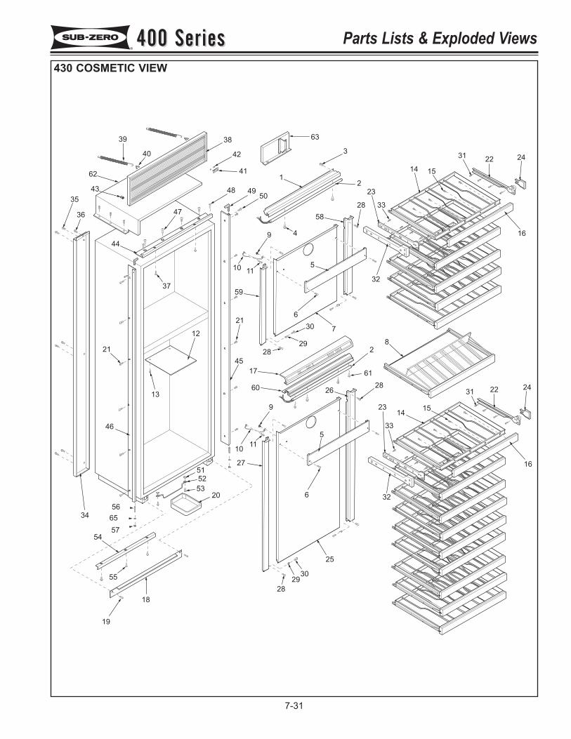
56
57
65
39
40
43
35
3647
38
42
41
48 4950
1
3
2
37
44
21
12
13
46
34
54
55
19
18
51
52
5320
27
1011
9
60
17
45
21
28
59
1011
9 4
58
5
28
23
33
32
6
30
29
7
2
61
2826
5
23
33
6 32
28
2930
25
1415
31 22 24
16
8
14 15
3122 24
16
62
63
400 Series400 Series Parts Lists & Exploded Views
7-31
430 COSMETIC VIEW
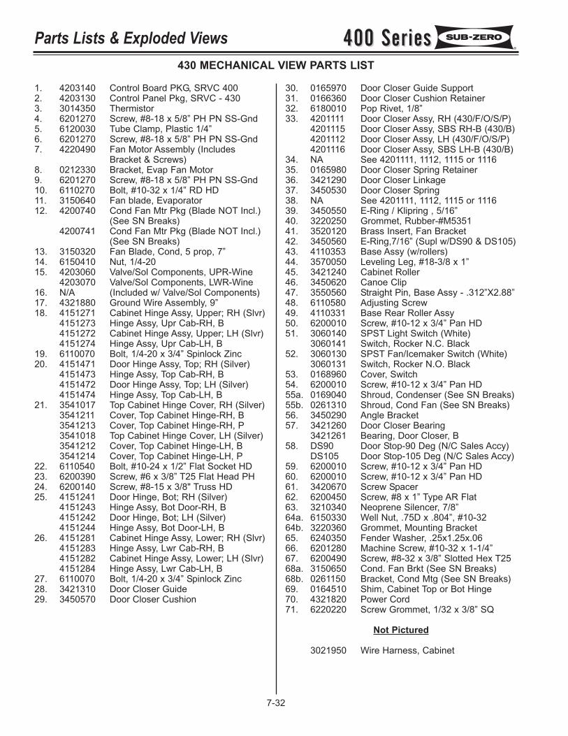
400 Series400 SeriesParts Lists & Exploded Views
7-32
430 MECHANICAL VIEW PARTS LIST
1. 4203140 Control Board PKG, SRVC 4002. 4203130 Control Panel Pkg, SRVC - 4303. 3014350 Thermistor4. 6201270 Screw, #8-18 x 5/8” PH PN SS-Gnd5. 6120030 Tube Clamp, Plastic 1/4”6. 6201270 Screw, #8-18 x 5/8” PH PN SS-Gnd7. 4220490 Fan Motor Assembly (Includes
Bracket & Screws)8. 0212330 Bracket, Evap Fan Motor9. 6201270 Screw, #8-18 x 5/8” PH PN SS-Gnd10. 6110270 Bolt, #10-32 x 1/4” RD HD11. 3150640 Fan blade, Evaporator12. 4200740 Cond Fan Mtr Pkg (Blade NOT Incl.)
(See SN Breaks)4200741 Cond Fan Mtr Pkg (Blade NOT Incl.)
(See SN Breaks)13. 3150320 Fan Blade, Cond, 5 prop, 7”14. 6150410 Nut, 1/4-2015. 4203060 Valve/Sol Components, UPR-Wine
4203070 Valve/Sol Components, LWR-Wine16. N/A (Included w/ Valve/Sol Components)17. 4321880 Ground Wire Assembly, 9”18. 4151271 Cabinet Hinge Assy, Upper; RH (Slvr)
4151273 Hinge Assy, Upr Cab-RH, B4151272 Cabinet Hinge Assy, Upper; LH (Slvr)4151274 Hinge Assy, Upr Cab-LH, B
19. 6110070 Bolt, 1/4-20 x 3/4” Spinlock Zinc20. 4151471 Door Hinge Assy, Top; RH (Silver)
4151473 Hinge Assy, Top Cab-RH, B4151472 Door Hinge Assy, Top; LH (Silver)4151474 Hinge Assy, Top Cab-LH, B
21. 3541017 Top Cabinet Hinge Cover, RH (Silver)3541211 Cover, Top Cabinet Hinge-RH, B3541213 Cover, Top Cabinet Hinge-RH, P3541018 Top Cabinet Hinge Cover, LH (Silver)3541212 Cover, Top Cabinet Hinge-LH, B3541214 Cover, Top Cabinet Hinge-LH, P
22. 6110540 Bolt, #10-24 x 1/2” Flat Socket HD23. 6200390 Screw, #6 x 3/8” T25 Flat Head PH24. 6200140 Screw, #8-15 x 3/8" Truss HD25. 4151241 Door Hinge, Bot; RH (Silver)
4151243 Hinge Assy, Bot Door-RH, B4151242 Door Hinge, Bot; LH (Silver)4151244 Hinge Assy, Bot Door-LH, B
26. 4151281 Cabinet Hinge Assy, Lower; RH (Slvr)4151283 Hinge Assy, Lwr Cab-RH, B4151282 Cabinet Hinge Assy, Lower; LH (Slvr)4151284 Hinge Assy, Lwr Cab-LH, B
27. 6110070 Bolt, 1/4-20 x 3/4” Spinlock Zinc28. 3421310 Door Closer Guide29. 3450570 Door Closer Cushion
30. 0165970 Door Closer Guide Support31. 0166360 Door Closer Cushion Retainer32. 6180010 Pop Rivet, 1/8”33. 4201111 Door Closer Assy, RH (430/F/O/S/P)
4201115 Door Closer Assy, SBS RH-B (430/B)4201112 Door Closer Assy, LH (430/F/O/S/P)4201116 Door Closer Assy, SBS LH-B (430/B)
34. NA See 4201111, 1112, 1115 or 111635. 0165980 Door Closer Spring Retainer36. 3421290 Door Closer Linkage37. 3450530 Door Closer Spring38. NA See 4201111, 1112, 1115 or 111639. 3450550 E-Ring / Klipring , 5/16”40. 3220250 Grommet, Rubber-#M535141. 3520120 Brass Insert, Fan Bracket42. 3450560 E-Ring,7/16” (Supl w/DS90 & DS105)43. 4110353 Base Assy (w/rollers)44. 3570050 Leveling Leg, #18-3/8 x 1”45. 3421240 Cabinet Roller46. 3450620 Canoe Clip47. 3550560 Straight Pin, Base Assy - .312”X2.88”48. 6110580 Adjusting Screw49. 4110331 Base Rear Roller Assy50. 6200010 Screw, #10-12 x 3/4” Pan HD51. 3060140 SPST Light Switch (White)
3060141 Switch, Rocker N.C. Black 52. 3060130 SPST Fan/Icemaker Switch (White)
3060131 Switch, Rocker N.O. Black53. 0168960 Cover, Switch54. 6200010 Screw, #10-12 x 3/4” Pan HD55a. 0169040 Shroud, Condenser (See SN Breaks)55b. 0261310 Shroud, Cond Fan (See SN Breaks)56. 3450290 Angle Bracket57. 3421260 Door Closer Bearing
3421261 Bearing, Door Closer, B58. DS90 Door Stop-90 Deg (N/C Sales Accy)
DS105 Door Stop-105 Deg (N/C Sales Accy)59. 6200010 Screw, #10-12 x 3/4” Pan HD60. 6200010 Screw, #10-12 x 3/4” Pan HD61. 3420670 Screw Spacer62. 6200450 Screw, #8 x 1” Type AR Flat63. 3210340 Neoprene Silencer, 7/8”64a. 6150330 Well Nut, .75D x .804”, #10-3264b. 3220360 Grommet, Mounting Bracket65. 6240350 Fender Washer, .25x1.25x.0666. 6201280 Machine Screw, #10-32 x 1-1/4”67. 6200490 Screw, #8-32 x 3/8” Slotted Hex T2568a. 3150650 Cond. Fan Brkt (See SN Breaks)68b. 0261150 Bracket, Cond Mtg (See SN Breaks)69. 0164510 Shim, Cabinet Top or Bot Hinge70. 4321820 Power Cord71. 6220220 Screw Grommet, 1/32 x 3/8” SQ
Not Pictured
3021950 Wire Harness, Cabinet
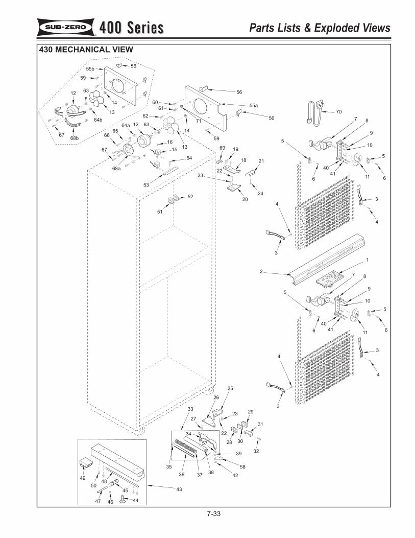
67
6665
64a 12 63
62
61
60
68a
16
15
54
53
13
14
59
71
51
52
23
22
20
24
2118
1969
55a
56
5
6
70
7 8
9
10
5
611
40
41
3
4
7 8
9
10
11
40
41
5
66
5
1
2
4
3
3
4
4
3
2329
31
32
3028
22
27
33
25
26
34
57
39
58
4238
3736
35
43
49
5048
47 46 44
45
56
59
13
14
68b67
6312
55b56
64b
400 Series400 Series Parts Lists & Exploded Views
7-33
430 MECHANICAL VIEW
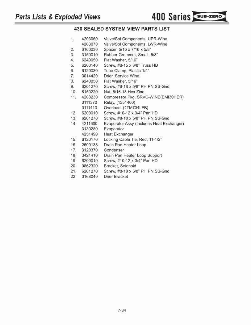
400 Series400 SeriesParts Lists & Exploded Views
7-34
430 SEALED SYSTEM VIEW PARTS LIST
1. 4203060 Valve/Sol Components, UPR-Wine4203070 Valve/Sol Components, LWR-Wine
2. 6160030 Spacer, 5/16 x 7/16 x 5/8”3. 3150010 Rubber Grommet, Small, 5/8”4. 6240050 Flat Washer, 5/16”5. 6200140 Screw, #8-15 x 3/8” Truss HD6. 6120030 Tube Clamp, Plastic 1/4”7. 3014420 Drier, Service Wine8. 6240050 Flat Washer, 5/16”9. 6201270 Screw, #8-18 x 5/8” PH PN SS-Gnd10. 6150220 Nut, 5/16-18 Hex Zinc11. 4203230 Compressor Pkg. SRVC-WINE(EMI30HER)
3111370 Relay, (1351400)3111410 Overload, (4TM734LFB)
12. 6200010 Screw, #10-12 x 3/4” Pan HD13. 6201270 Screw, #8-18 x 5/8” PH PN SS-Gnd14. 4211600 Evaporator Assy (Includes Heat Exchanger)
3130280 Evaporator4251490 Heat Exchanger
15. 6120170 Locking Cable Tie, Red, 11-1/2”16. 2600138 Drain Pan Heater Loop17. 3120370 Condenser18. 3421410 Drain Pan Heater Loop Support19 6200010 Screw, #10-12 x 3/4” Pan HD20. 0862320 Bracket, Solenoid21. 6201270 Screw, #8-18 x 5/8” PH PN SS-Gnd22. 0168040 Drier Bracket
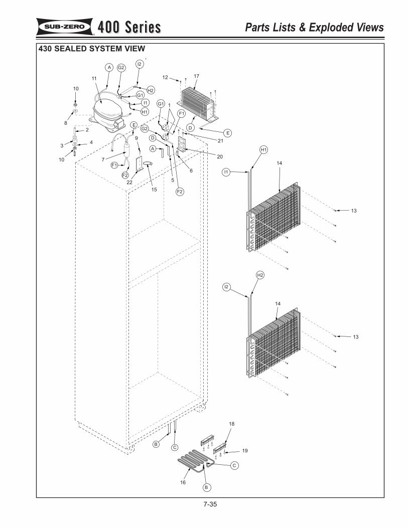
B
A
B
C
C
D
F2
F1
F2
G1
G2
H1
H2
I1
I2
H1
G2
H2
I1
A
G1
I2
DE
E
F1
10
82
3 4
10 7
2215
5
6
9
20
21
12 1711
1
14
13
14
13
18
19
16
400 Series400 Series Parts Lists & Exploded Views
7-35
430 SEALED SYSTEM VIEW
400 Series400 SeriesParts Lists & Exploded View Notes
7-36
400 Series400 Series Troubleshooting Guides
8-1
SECTION 8
TROUBLESHOOTINGGUIDES
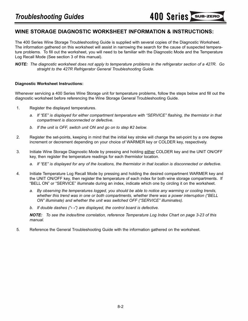
400 Series400 SeriesTroubleshooting Guides
8-2
WINE STORAGE DIAGNOSTIC WORKSHEET INFORMATION & INSTRUCTIONS:
The 400 Series Wine Storage Troubleshooting Guide is supplied with several copies of the Diagnostic Worksheet.The information gathered on this worksheet will assist in narrowing the search for the cause of suspected tempera-ture problems. To fill out the worksheet, you will need to be familiar with the Diagnostic Mode and the TemperatureLog Recall Mode (See section 3 of this manual).
NOTE: The diagnostic worksheet does not apply to temperature problems in the refrigerator section of a 427R. Gostraight to the 427R Refrigerator General Troubleshooting Guide.
Diagnostic Worksheet Instructions:
Whenever servicing a 400 Series Wine Storage unit for temperature problems, follow the steps below and fill out thediagnostic worksheet before referencing the Wine Storage General Troubleshooting Guide.
1. Register the displayed temperatures.
a. If “EE” is displayed for either compartment temperature with “SERVICE” flashing, the thermistor in thatcompartment is disconnected or defective.
b. If the unit is OFF, switch unit ON and go on to step #2 below.
2. Register the set-points, keeping in mind that the initial key stroke will change the set-point by a one degreeincrement or decrement depending on your choice of WARMER key or COLDER key, respectively.
3. Initiate Wine Storage Diagnostic Mode by pressing and holding either COLDER key and the UNIT ON/OFFkey, then register the temperature readings for each thermistor location.
a. If “EE” is displayed for any of the locations, the thermistor in that location is disconnected or defective.
4. Initiate Temperature Log Recall Mode by pressing and holding the desired compartment WARMER key andthe UNIT ON/OFF key, then register the temperature of each index for both wine storage compartments. If“BELL ON” or “SERVICE” illuminate during an index, indicate which one by circling it on the worksheet.
a. By observing the temperatures logged, you should be able to notice any warming or cooling trends,whether this trend was in one or both compartments, whether there was a power interruption (“BELLON” illuminate) and whether the unit was switched OFF (“SERVICE” illuminates).
b. If double dashes (“- -”) are displayed, the control board is defective.
NOTE: To see the index/time correlation, reference Temperature Log Index Chart on page 3-23 of thismanual.
5. Reference the General Troubleshooting Guide with the information gathered on the worksheet.
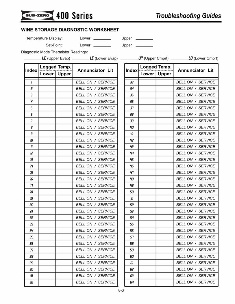
400 Series400 Series Troubleshooting Guides
8-3
Logged Temp.UpperLower
WINE STORAGE DIAGNOSTIC WORKSHEETTemperature Display: Lower Upper
Set-Point: Lower Upper
Diagnostic Mode Thermistor Readings:UE (Upper Evap) LE (Lower Evap) UP (Upper Cmprt) LO (Lower Cmprt)
1
2
3
4
5
6
7
8
9
10
11
12
13
14
15
16
17
18
19
20
21
22
23
24
25
26
27
28
29
30
31
32
Index
BELL ON / SERVICEBELL ON / SERVICEBELL ON / SERVICEBELL ON / SERVICEBELL ON / SERVICEBELL ON / SERVICEBELL ON / SERVICEBELL ON / SERVICEBELL ON / SERVICEBELL ON / SERVICEBELL ON / SERVICEBELL ON / SERVICEBELL ON / SERVICEBELL ON / SERVICEBELL ON / SERVICEBELL ON / SERVICEBELL ON / SERVICEBELL ON / SERVICEBELL ON / SERVICEBELL ON / SERVICEBELL ON / SERVICEBELL ON / SERVICEBELL ON / SERVICEBELL ON / SERVICEBELL ON / SERVICEBELL ON / SERVICEBELL ON / SERVICEBELL ON / SERVICEBELL ON / SERVICEBELL ON / SERVICEBELL ON / SERVICEBELL ON / SERVICE
Annunciator LitLogged Temp.
UpperLower33
34
35
36
37
38
39
40
41
42
43
44
45
46
47
48
49
50
51
52
53
54
55
56
57
58
59
60
61
62
63
64
Index
BELL ON / SERVICEBELL ON / SERVICEBELL ON / SERVICEBELL ON / SERVICEBELL ON / SERVICEBELL ON / SERVICEBELL ON / SERVICEBELL ON / SERVICEBELL ON / SERVICEBELL ON / SERVICEBELL ON / SERVICEBELL ON / SERVICEBELL ON / SERVICEBELL ON / SERVICEBELL ON / SERVICEBELL ON / SERVICEBELL ON / SERVICEBELL ON / SERVICEBELL ON / SERVICEBELL ON / SERVICEBELL ON / SERVICEBELL ON / SERVICEBELL ON / SERVICEBELL ON / SERVICEBELL ON / SERVICEBELL ON / SERVICEBELL ON / SERVICEBELL ON / SERVICEBELL ON / SERVICEBELL ON / SERVICEBELL ON / SERVICEBELL ON / SERVICE
Annunciator Lit
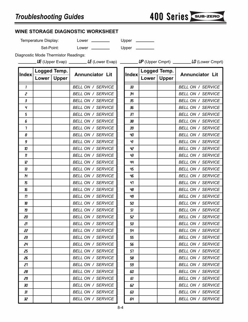
400 Series400 SeriesTroubleshooting Guides
8-4
Logged Temp.UpperLower
WINE STORAGE DIAGNOSTIC WORKSHEETTemperature Display: Lower Upper
Set-Point: Lower Upper
Diagnostic Mode Thermistor Readings:UE (Upper Evap) LE (Lower Evap) UP (Upper Cmprt) LO (Lower Cmprt)
1
2
3
4
5
6
7
8
9
10
11
12
13
14
15
16
17
18
19
20
21
22
23
24
25
26
27
28
29
30
31
32
Index
BELL ON / SERVICEBELL ON / SERVICEBELL ON / SERVICEBELL ON / SERVICEBELL ON / SERVICEBELL ON / SERVICEBELL ON / SERVICEBELL ON / SERVICEBELL ON / SERVICEBELL ON / SERVICEBELL ON / SERVICEBELL ON / SERVICEBELL ON / SERVICEBELL ON / SERVICEBELL ON / SERVICEBELL ON / SERVICEBELL ON / SERVICEBELL ON / SERVICEBELL ON / SERVICEBELL ON / SERVICEBELL ON / SERVICEBELL ON / SERVICEBELL ON / SERVICEBELL ON / SERVICEBELL ON / SERVICEBELL ON / SERVICEBELL ON / SERVICEBELL ON / SERVICEBELL ON / SERVICEBELL ON / SERVICEBELL ON / SERVICEBELL ON / SERVICE
Annunciator LitLogged Temp.
UpperLower33
34
35
36
37
38
39
40
41
42
43
44
45
46
47
48
49
50
51
52
53
54
55
56
57
58
59
60
61
62
63
64
Index
BELL ON / SERVICEBELL ON / SERVICEBELL ON / SERVICEBELL ON / SERVICEBELL ON / SERVICEBELL ON / SERVICEBELL ON / SERVICEBELL ON / SERVICEBELL ON / SERVICEBELL ON / SERVICEBELL ON / SERVICEBELL ON / SERVICEBELL ON / SERVICEBELL ON / SERVICEBELL ON / SERVICEBELL ON / SERVICEBELL ON / SERVICEBELL ON / SERVICEBELL ON / SERVICEBELL ON / SERVICEBELL ON / SERVICEBELL ON / SERVICEBELL ON / SERVICEBELL ON / SERVICEBELL ON / SERVICEBELL ON / SERVICEBELL ON / SERVICEBELL ON / SERVICEBELL ON / SERVICEBELL ON / SERVICEBELL ON / SERVICEBELL ON / SERVICE
Annunciator Lit

400 Series400 Series Troubleshooting Guides
8-5
Logged Temp.UpperLower
WINE STORAGE DIAGNOSTIC WORKSHEETTemperature Display: Lower Upper
Set-Point: Lower Upper
Diagnostic Mode Thermistor Readings:UE (Upper Evap) LE (Lower Evap) UP (Upper Cmprt) LO (Lower Cmprt)
1
2
3
4
5
6
7
8
9
10
11
12
13
14
15
16
17
18
19
20
21
22
23
24
25
26
27
28
29
30
31
32
Index
BELL ON / SERVICEBELL ON / SERVICEBELL ON / SERVICEBELL ON / SERVICEBELL ON / SERVICEBELL ON / SERVICEBELL ON / SERVICEBELL ON / SERVICEBELL ON / SERVICEBELL ON / SERVICEBELL ON / SERVICEBELL ON / SERVICEBELL ON / SERVICEBELL ON / SERVICEBELL ON / SERVICEBELL ON / SERVICEBELL ON / SERVICEBELL ON / SERVICEBELL ON / SERVICEBELL ON / SERVICEBELL ON / SERVICEBELL ON / SERVICEBELL ON / SERVICEBELL ON / SERVICEBELL ON / SERVICEBELL ON / SERVICEBELL ON / SERVICEBELL ON / SERVICEBELL ON / SERVICEBELL ON / SERVICEBELL ON / SERVICEBELL ON / SERVICE
Annunciator LitLogged Temp.
UpperLower33
34
35
36
37
38
39
40
41
42
43
44
45
46
47
48
49
50
51
52
53
54
55
56
57
58
59
60
61
62
63
64
Index
BELL ON / SERVICEBELL ON / SERVICEBELL ON / SERVICEBELL ON / SERVICEBELL ON / SERVICEBELL ON / SERVICEBELL ON / SERVICEBELL ON / SERVICEBELL ON / SERVICEBELL ON / SERVICEBELL ON / SERVICEBELL ON / SERVICEBELL ON / SERVICEBELL ON / SERVICEBELL ON / SERVICEBELL ON / SERVICEBELL ON / SERVICEBELL ON / SERVICEBELL ON / SERVICEBELL ON / SERVICEBELL ON / SERVICEBELL ON / SERVICEBELL ON / SERVICEBELL ON / SERVICEBELL ON / SERVICEBELL ON / SERVICEBELL ON / SERVICEBELL ON / SERVICEBELL ON / SERVICEBELL ON / SERVICEBELL ON / SERVICEBELL ON / SERVICE
Annunciator Lit

400 Series400 SeriesTroubleshooting Guides
8-6
Logged Temp.UpperLower
WINE STORAGE DIAGNOSTIC WORKSHEETTemperature Display: Lower Upper
Set-Point: Lower Upper
Diagnostic Mode Thermistor Readings:UE (Upper Evap) LE (Lower Evap) UP (Upper Cmprt) LO (Lower Cmprt)
1
2
3
4
5
6
7
8
9
10
11
12
13
14
15
16
17
18
19
20
21
22
23
24
25
26
27
28
29
30
31
32
Index
BELL ON / SERVICEBELL ON / SERVICEBELL ON / SERVICEBELL ON / SERVICEBELL ON / SERVICEBELL ON / SERVICEBELL ON / SERVICEBELL ON / SERVICEBELL ON / SERVICEBELL ON / SERVICEBELL ON / SERVICEBELL ON / SERVICEBELL ON / SERVICEBELL ON / SERVICEBELL ON / SERVICEBELL ON / SERVICEBELL ON / SERVICEBELL ON / SERVICEBELL ON / SERVICEBELL ON / SERVICEBELL ON / SERVICEBELL ON / SERVICEBELL ON / SERVICEBELL ON / SERVICEBELL ON / SERVICEBELL ON / SERVICEBELL ON / SERVICEBELL ON / SERVICEBELL ON / SERVICEBELL ON / SERVICEBELL ON / SERVICEBELL ON / SERVICE
Annunciator LitLogged Temp.
UpperLower33
34
35
36
37
38
39
40
41
42
43
44
45
46
47
48
49
50
51
52
53
54
55
56
57
58
59
60
61
62
63
64
Index
BELL ON / SERVICEBELL ON / SERVICEBELL ON / SERVICEBELL ON / SERVICEBELL ON / SERVICEBELL ON / SERVICEBELL ON / SERVICEBELL ON / SERVICEBELL ON / SERVICEBELL ON / SERVICEBELL ON / SERVICEBELL ON / SERVICEBELL ON / SERVICEBELL ON / SERVICEBELL ON / SERVICEBELL ON / SERVICEBELL ON / SERVICEBELL ON / SERVICEBELL ON / SERVICEBELL ON / SERVICEBELL ON / SERVICEBELL ON / SERVICEBELL ON / SERVICEBELL ON / SERVICEBELL ON / SERVICEBELL ON / SERVICEBELL ON / SERVICEBELL ON / SERVICEBELL ON / SERVICEBELL ON / SERVICEBELL ON / SERVICEBELL ON / SERVICE
Annunciator Lit
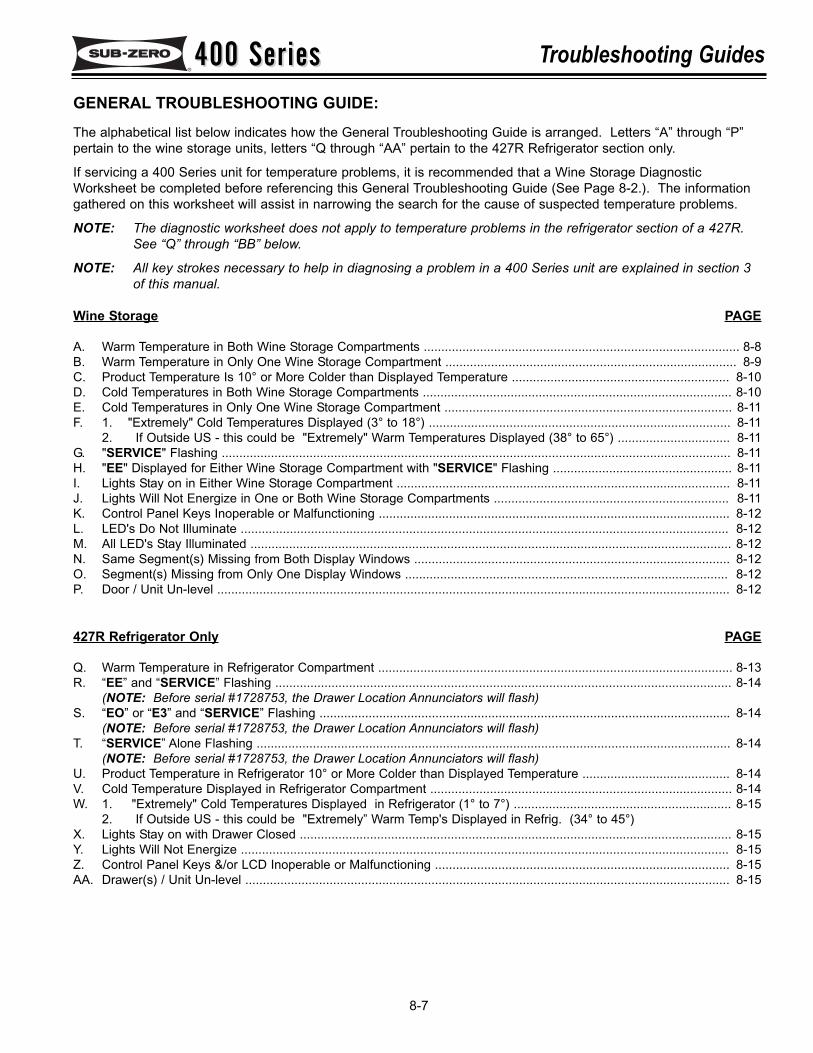
400 Series400 Series Troubleshooting Guides
8-7
GENERAL TROUBLESHOOTING GUIDE:The alphabetical list below indicates how the General Troubleshooting Guide is arranged. Letters “A” through “P”pertain to the wine storage units, letters “Q through “AA” pertain to the 427R Refrigerator section only.
If servicing a 400 Series unit for temperature problems, it is recommended that a Wine Storage DiagnosticWorksheet be completed before referencing this General Troubleshooting Guide (See Page 8-2.). The informationgathered on this worksheet will assist in narrowing the search for the cause of suspected temperature problems.
NOTE: The diagnostic worksheet does not apply to temperature problems in the refrigerator section of a 427R.See “Q” through “BB” below.
NOTE: All key strokes necessary to help in diagnosing a problem in a 400 Series unit are explained in section 3of this manual.
Wine Storage PAGE
A. Warm Temperature in Both Wine Storage Compartments .......................................................................................... 8-8B. Warm Temperature in Only One Wine Storage Compartment ................................................................................... 8-9C. Product Temperature Is 10° or More Colder than Displayed Temperature .............................................................. 8-10D. Cold Temperatures in Both Wine Storage Compartments ........................................................................................ 8-10E. Cold Temperatures in Only One Wine Storage Compartment .................................................................................. 8-11F. 1. "Extremely" Cold Temperatures Displayed (3° to 18°) ...................................................................................... 8-11
2. If Outside US - this could be "Extremely" Warm Temperatures Displayed (38° to 65°) ................................ 8-11G. "SERVICE" Flashing ................................................................................................................................................. 8-11H. "EE" Displayed for Either Wine Storage Compartment with "SERVICE" Flashing ................................................... 8-11I. Lights Stay on in Either Wine Storage Compartment ............................................................................................... 8-11J. Lights Will Not Energize in One or Both Wine Storage Compartments ................................................................... 8-11K. Control Panel Keys Inoperable or Malfunctioning .................................................................................................... 8-12L. LED's Do Not Illuminate ........................................................................................................................................... 8-12M. All LED's Stay Illuminated ......................................................................................................................................... 8-12N. Same Segment(s) Missing from Both Display Windows .......................................................................................... 8-12O. Segment(s) Missing from Only One Display Windows ............................................................................................ 8-12P. Door / Unit Un-level .................................................................................................................................................. 8-12
427R Refrigerator Only PAGE
Q. Warm Temperature in Refrigerator Compartment ..................................................................................................... 8-13R. “EE” and “SERVICE” Flashing .................................................................................................................................. 8-14
(NOTE: Before serial #1728753, the Drawer Location Annunciators will flash)S. “EO” or “E3” and “SERVICE” Flashing ..................................................................................................................... 8-14
(NOTE: Before serial #1728753, the Drawer Location Annunciators will flash)T. “SERVICE” Alone Flashing ....................................................................................................................................... 8-14
(NOTE: Before serial #1728753, the Drawer Location Annunciators will flash)U. Product Temperature in Refrigerator 10° or More Colder than Displayed Temperature .......................................... 8-14V. Cold Temperature Displayed in Refrigerator Compartment ...................................................................................... 8-14W. 1. "Extremely" Cold Temperatures Displayed in Refrigerator (1° to 7°) .............................................................. 8-15
2. If Outside US - this could be "Extremely” Warm Temp's Displayed in Refrig. (34° to 45°)X. Lights Stay on with Drawer Closed ........................................................................................................................... 8-15Y. Lights Will Not Energize ........................................................................................................................................... 8-15Z. Control Panel Keys &/or LCD Inoperable or Malfunctioning .................................................................................... 8-15AA. Drawer(s) / Unit Un-level .......................................................................................................................................... 8-15
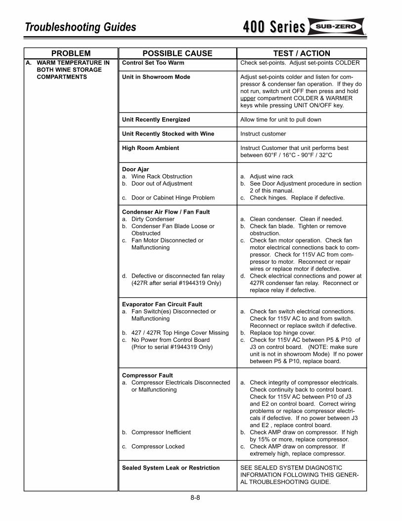
400 Series400 SeriesTroubleshooting Guides
8-8
A. WARM TEMPERATURE INBOTH WINE STORAGECOMPARTMENTS
Control Set Too Warm
Unit in Showroom Mode
Unit Recently Energized
Unit Recently Stocked with Wine
High Room Ambient
Door Ajara. Wine Rack Obstructionb. Door out of Adjustment
c. Door or Cabinet Hinge Problem
Condenser Air Flow / Fan Faulta. Dirty Condenserb. Condenser Fan Blade Loose or
Obstructedc. Fan Motor Disconnected or
Malfunctioning
d. Defective or disconnected fan relay(427R after serial #1944319 Only)
Evaporator Fan Circuit Faulta. Fan Switch(es) Disconnected or
Malfunctioning
b. 427 / 427R Top Hinge Cover Missingc. No Power from Control Board
(Prior to serial #1944319 Only)
Compressor Fault a. Compressor Electricals Disconnected
or Malfunctioning
b. Compressor Inefficient
c. Compressor Locked
Sealed System Leak or Restriction
Check set-points. Adjust set-points COLDER
Adjust set-points colder and listen for com-pressor & condenser fan operation. If they donot run, switch unit OFF then press and holdupper compartment COLDER & WARMERkeys while pressing UNIT ON/OFF key.
Allow time for unit to pull down
Instruct customer
Instruct Customer that unit performs bestbetween 60°F / 16°C - 90°F / 32°C
a. Adjust wine rackb. See Door Adjustment procedure in section
2 of this manual.c. Check hinges. Replace if defective.
a. Clean condenser. Clean if needed.b. Check fan blade. Tighten or remove
obstruction.c. Check fan motor operation. Check fan
motor electrical connections back to com-pressor. Check for 115V AC from com-pressor to motor. Reconnect or repairwires or replace motor if defective.
d. Check electrical connections and power at427R condenser fan relay. Reconnect orreplace relay if defective.
a. Check fan switch electrical connections.Check for 115V AC to and from switch.Reconnect or replace switch if defective.
b. Replace top hinge cover.c. Check for 115V AC between P5 & P10 of
J3 on control board. (NOTE: make sureunit is not in showroom Mode) If no powerbetween P5 & P10, replace board.
a. Check integrity of compressor electricals.Check continuity back to control board.Check for 115V AC between P10 of J3and E2 on control board. Correct wiringproblems or replace compressor electri-cals if defective. If no power between J3and E2 , replace control board.
b. Check AMP draw on compressor. If highby 15% or more, replace compressor.
c. Check AMP draw on compressor. Ifextremely high, replace compressor.
SEE SEALED SYSTEM DIAGNOSTICINFORMATION FOLLOWING THIS GENER-AL TROUBLESHOOTING GUIDE.
PROBLEM POSSIBLE CAUSE TEST / ACTION
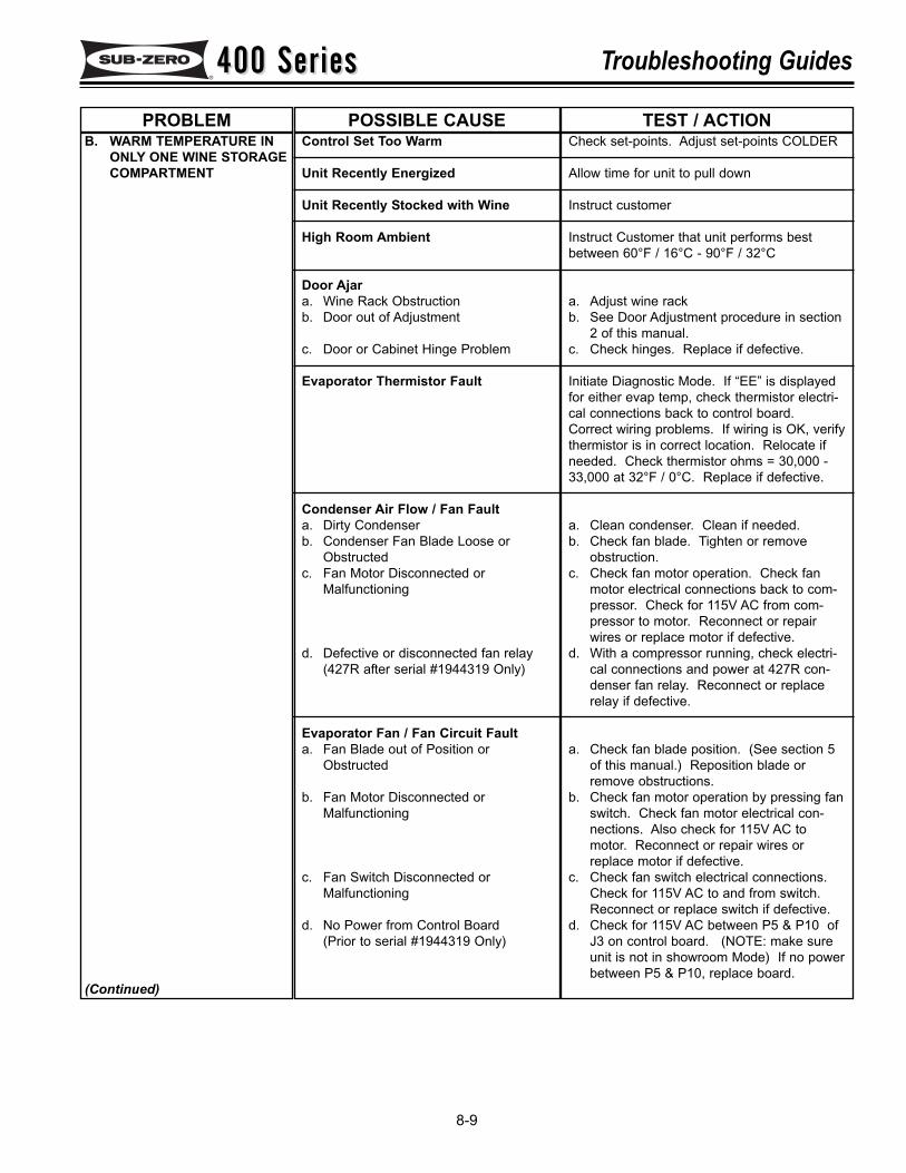
400 Series400 Series Troubleshooting Guides
8-9
B. WARM TEMPERATURE INONLY ONE WINE STORAGECOMPARTMENT
(Continued)
Control Set Too Warm
Unit Recently Energized
Unit Recently Stocked with Wine
High Room Ambient
Door Ajara. Wine Rack Obstructionb. Door out of Adjustment
c. Door or Cabinet Hinge Problem
Evaporator Thermistor Fault
Condenser Air Flow / Fan Faulta. Dirty Condenserb. Condenser Fan Blade Loose or
Obstructedc. Fan Motor Disconnected or
Malfunctioning
d. Defective or disconnected fan relay(427R after serial #1944319 Only)
Evaporator Fan / Fan Circuit Faulta. Fan Blade out of Position or
Obstructed
b. Fan Motor Disconnected orMalfunctioning
c. Fan Switch Disconnected orMalfunctioning
d. No Power from Control Board(Prior to serial #1944319 Only)
Check set-points. Adjust set-points COLDER
Allow time for unit to pull down
Instruct customer
Instruct Customer that unit performs bestbetween 60°F / 16°C - 90°F / 32°C
a. Adjust wine rackb. See Door Adjustment procedure in section
2 of this manual.c. Check hinges. Replace if defective.
Initiate Diagnostic Mode. If “EE” is displayedfor either evap temp, check thermistor electri-cal connections back to control board.Correct wiring problems. If wiring is OK, verifythermistor is in correct location. Relocate ifneeded. Check thermistor ohms = 30,000 -33,000 at 32°F / 0°C. Replace if defective.
a. Clean condenser. Clean if needed.b. Check fan blade. Tighten or remove
obstruction.c. Check fan motor operation. Check fan
motor electrical connections back to com-pressor. Check for 115V AC from com-pressor to motor. Reconnect or repairwires or replace motor if defective.
d. With a compressor running, check electri-cal connections and power at 427R con-denser fan relay. Reconnect or replacerelay if defective.
a. Check fan blade position. (See section 5of this manual.) Reposition blade orremove obstructions.
b. Check fan motor operation by pressing fanswitch. Check fan motor electrical con-nections. Also check for 115V AC tomotor. Reconnect or repair wires orreplace motor if defective.
c. Check fan switch electrical connections.Check for 115V AC to and from switch.Reconnect or replace switch if defective.
d. Check for 115V AC between P5 & P10 ofJ3 on control board. (NOTE: make sureunit is not in showroom Mode) If no powerbetween P5 & P10, replace board.
PROBLEM POSSIBLE CAUSE TEST / ACTION
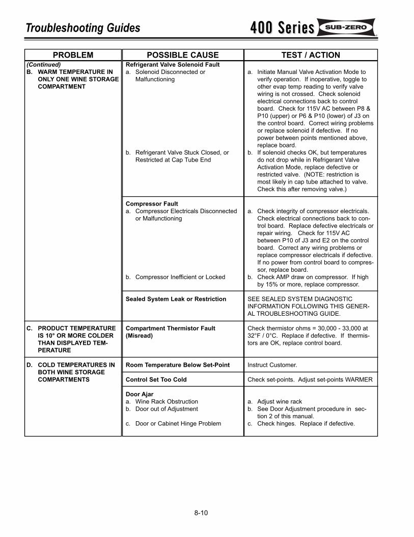
400 Series400 SeriesTroubleshooting Guides
8-10
(Continued)B. WARM TEMPERATURE IN
ONLY ONE WINE STORAGECOMPARTMENT
C. PRODUCT TEMPERATUREIS 10° OR MORE COLDERTHAN DISPLAYED TEM-PERATURE
D. COLD TEMPERATURES INBOTH WINE STORAGECOMPARTMENTS
Refrigerant Valve Solenoid Faulta. Solenoid Disconnected or
Malfunctioning
b. Refrigerant Valve Stuck Closed, orRestricted at Cap Tube End
Compressor Fault a. Compressor Electricals Disconnected
or Malfunctioning
b. Compressor Inefficient or Locked
Sealed System Leak or Restriction
Compartment Thermistor Fault(Misread)
Room Temperature Below Set-Point
Control Set Too Cold
Door Ajara. Wine Rack Obstructionb. Door out of Adjustment
c. Door or Cabinet Hinge Problem
a. Initiate Manual Valve Activation Mode toverify operation. If inoperative, toggle toother evap temp reading to verify valvewiring is not crossed. Check solenoidelectrical connections back to controlboard. Check for 115V AC between P8 &P10 (upper) or P6 & P10 (lower) of J3 onthe control board. Correct wiring problemsor replace solenoid if defective. If nopower between points mentioned above,replace board.
b. If solenoid checks OK, but temperaturesdo not drop while in Refrigerant ValveActivation Mode, replace defective orrestricted valve. (NOTE: restriction ismost likely in cap tube attached to valve.Check this after removing valve.)
a. Check integrity of compressor electricals.Check electrical connections back to con-trol board. Replace defective electricals orrepair wiring. Check for 115V ACbetween P10 of J3 and E2 on the controlboard. Correct any wiring problems orreplace compressor electricals if defective.If no power from control board to compres-sor, replace board.
b. Check AMP draw on compressor. If highby 15% or more, replace compressor.
SEE SEALED SYSTEM DIAGNOSTICINFORMATION FOLLOWING THIS GENER-AL TROUBLESHOOTING GUIDE.
Check thermistor ohms = 30,000 - 33,000 at32°F / 0°C. Replace if defective. If thermis-tors are OK, replace control board.
Instruct Customer.
Check set-points. Adjust set-points WARMER
a. Adjust wine rackb. See Door Adjustment procedure in sec-
tion 2 of this manual.c. Check hinges. Replace if defective.
PROBLEM POSSIBLE CAUSE TEST / ACTION
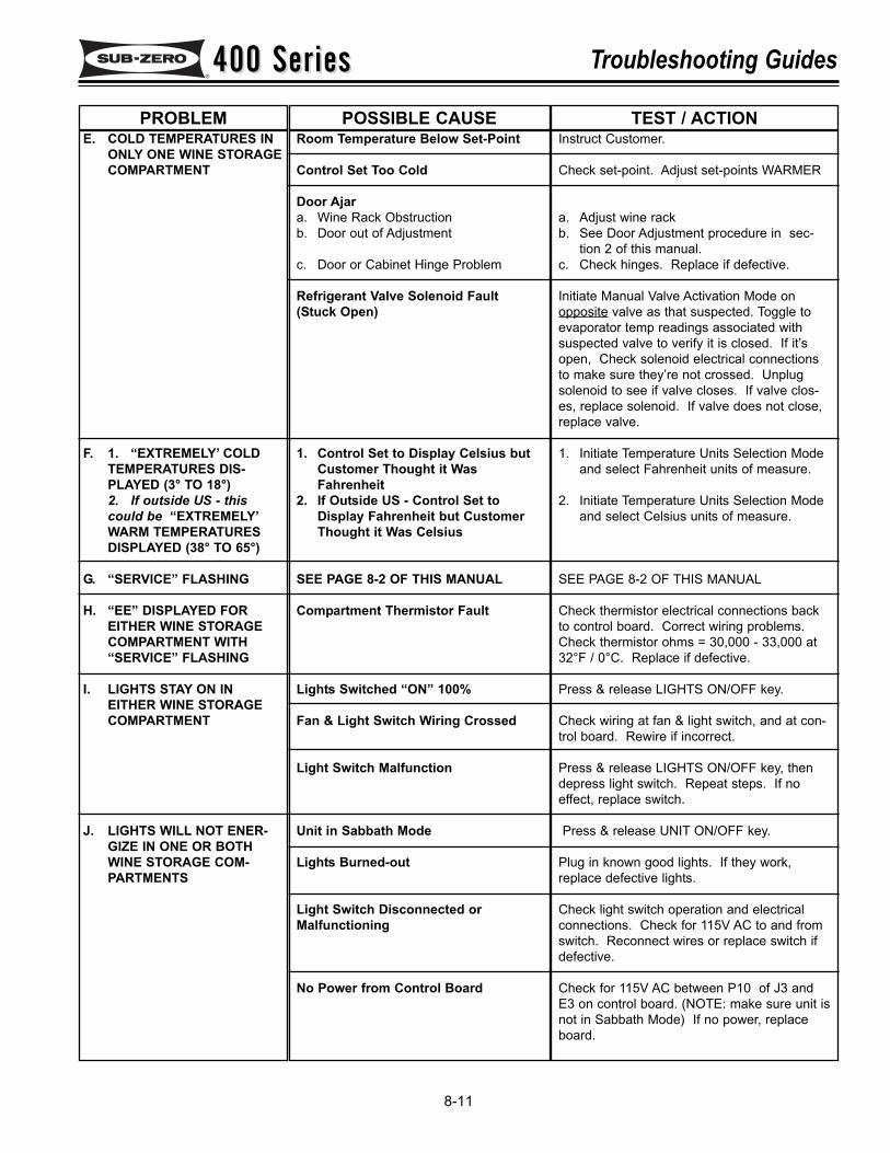
400 Series400 Series Troubleshooting Guides
8-11
E. COLD TEMPERATURES INONLY ONE WINE STORAGECOMPARTMENT
F. 1. “EXTREMELY’ COLDTEMPERATURES DIS-PLAYED (3° TO 18°)2. If outside US - thiscould be “EXTREMELY’WARM TEMPERATURESDISPLAYED (38° TO 65°)
G. “SERVICE” FLASHING
H. “EE” DISPLAYED FOREITHER WINE STORAGECOMPARTMENT WITH“SERVICE” FLASHING
I. LIGHTS STAY ON INEITHER WINE STORAGECOMPARTMENT
J. LIGHTS WILL NOT ENER-GIZE IN ONE OR BOTHWINE STORAGE COM-PARTMENTS
Room Temperature Below Set-Point
Control Set Too Cold
Door Ajara. Wine Rack Obstructionb. Door out of Adjustment
c. Door or Cabinet Hinge Problem
Refrigerant Valve Solenoid Fault(Stuck Open)
1. Control Set to Display Celsius butCustomer Thought it WasFahrenheit
2. If Outside US - Control Set toDisplay Fahrenheit but CustomerThought it Was Celsius
SEE PAGE 8-2 OF THIS MANUAL
Compartment Thermistor Fault
Lights Switched “ON” 100%
Fan & Light Switch Wiring Crossed
Light Switch Malfunction
Unit in Sabbath Mode
Lights Burned-out
Light Switch Disconnected orMalfunctioning
No Power from Control Board
Instruct Customer.
Check set-point. Adjust set-points WARMER
a. Adjust wine rackb. See Door Adjustment procedure in sec-
tion 2 of this manual.c. Check hinges. Replace if defective.
Initiate Manual Valve Activation Mode onopposite valve as that suspected. Toggle toevaporator temp readings associated withsuspected valve to verify it is closed. If it’sopen, Check solenoid electrical connectionsto make sure they’re not crossed. Unplugsolenoid to see if valve closes. If valve clos-es, replace solenoid. If valve does not close,replace valve.
1. Initiate Temperature Units Selection Modeand select Fahrenheit units of measure.
2. Initiate Temperature Units Selection Modeand select Celsius units of measure.
SEE PAGE 8-2 OF THIS MANUAL
Check thermistor electrical connections backto control board. Correct wiring problems.Check thermistor ohms = 30,000 - 33,000 at32°F / 0°C. Replace if defective.
Press & release LIGHTS ON/OFF key.
Check wiring at fan & light switch, and at con-trol board. Rewire if incorrect.
Press & release LIGHTS ON/OFF key, thendepress light switch. Repeat steps. If noeffect, replace switch.
Press & release UNIT ON/OFF key.
Plug in known good lights. If they work,replace defective lights.
Check light switch operation and electricalconnections. Check for 115V AC to and fromswitch. Reconnect wires or replace switch ifdefective.
Check for 115V AC between P10 of J3 andE3 on control board. (NOTE: make sure unit isnot in Sabbath Mode) If no power, replaceboard.
PROBLEM POSSIBLE CAUSE TEST / ACTION
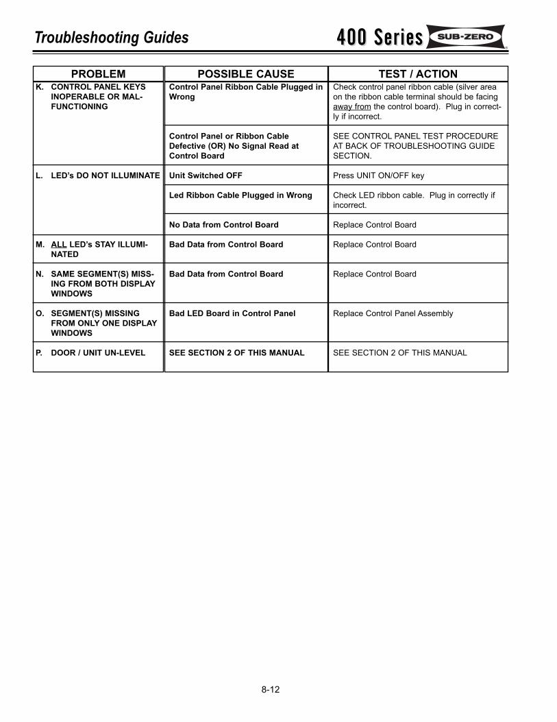
400 Series400 SeriesTroubleshooting Guides
8-12
K. CONTROL PANEL KEYSINOPERABLE OR MAL-FUNCTIONING
L. LED’s DO NOT ILLUMINATE
M. ALL LED’s STAY ILLUMI-NATED
N. SAME SEGMENT(S) MISS-ING FROM BOTH DISPLAYWINDOWS
O. SEGMENT(S) MISSINGFROM ONLY ONE DISPLAYWINDOWS
P. DOOR / UNIT UN-LEVEL
Control Panel Ribbon Cable Plugged inWrong
Control Panel or Ribbon CableDefective (OR) No Signal Read atControl Board
Unit Switched OFF
Led Ribbon Cable Plugged in Wrong
No Data from Control Board
Bad Data from Control Board
Bad Data from Control Board
Bad LED Board in Control Panel
SEE SECTION 2 OF THIS MANUAL
Check control panel ribbon cable (silver areaon the ribbon cable terminal should be facingaway from the control board). Plug in correct-ly if incorrect.
SEE CONTROL PANEL TEST PROCEDUREAT BACK OF TROUBLESHOOTING GUIDESECTION.
Press UNIT ON/OFF key
Check LED ribbon cable. Plug in correctly ifincorrect.
Replace Control Board
Replace Control Board
Replace Control Board
Replace Control Panel Assembly
SEE SECTION 2 OF THIS MANUAL
PROBLEM POSSIBLE CAUSE TEST / ACTION
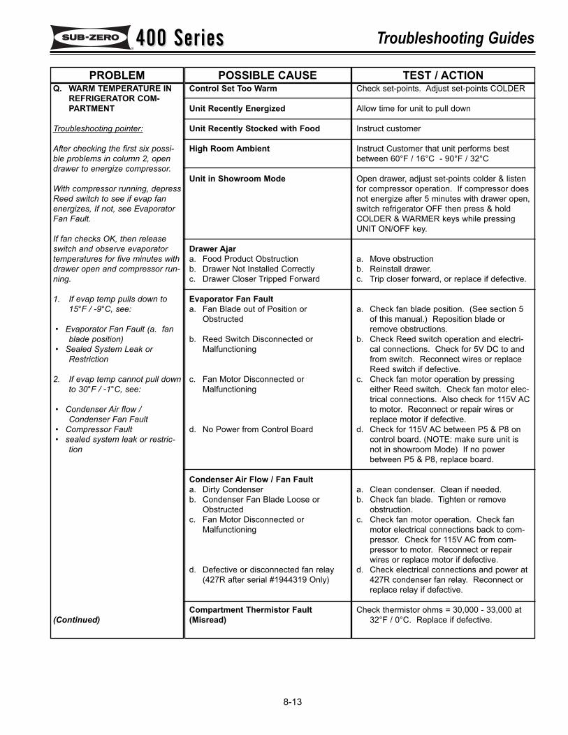
400 Series400 Series Troubleshooting Guides
8-13
Q. WARM TEMPERATURE INREFRIGERATOR COM-PARTMENT
Troubleshooting pointer:
After checking the first six possi-ble problems in column 2, opendrawer to energize compressor.
With compressor running, depressReed switch to see if evap fanenergizes, If not, see EvaporatorFan Fault.
If fan checks OK, then releaseswitch and observe evaporatortemperatures for five minutes withdrawer open and compressor run-ning.
1. If evap temp pulls down to15°F / -9°C, see:
• Evaporator Fan Fault (a. fanblade position)
• Sealed System Leak orRestriction
2. If evap temp cannot pull downto 30°F / -1°C, see:
• Condenser Air flow /Condenser Fan Fault
• Compressor Fault • sealed system leak or restric-
tion
(Continued)
Control Set Too Warm
Unit Recently Energized
Unit Recently Stocked with Food
High Room Ambient
Unit in Showroom Mode
Drawer Ajara. Food Product Obstructionb. Drawer Not Installed Correctlyc. Drawer Closer Tripped Forward
Evaporator Fan Faulta. Fan Blade out of Position or
Obstructed
b. Reed Switch Disconnected orMalfunctioning
c. Fan Motor Disconnected orMalfunctioning
d. No Power from Control Board
Condenser Air Flow / Fan Faulta. Dirty Condenserb. Condenser Fan Blade Loose or
Obstructedc. Fan Motor Disconnected or
Malfunctioning
d. Defective or disconnected fan relay(427R after serial #1944319 Only)
Compartment Thermistor Fault(Misread)
Check set-points. Adjust set-points COLDER
Allow time for unit to pull down
Instruct customer
Instruct Customer that unit performs bestbetween 60°F / 16°C - 90°F / 32°C
Open drawer, adjust set-points colder & listenfor compressor operation. If compressor doesnot energize after 5 minutes with drawer open,switch refrigerator OFF then press & holdCOLDER & WARMER keys while pressingUNIT ON/OFF key.
a. Move obstructionb. Reinstall drawer.c. Trip closer forward, or replace if defective.
a. Check fan blade position. (See section 5of this manual.) Reposition blade orremove obstructions.
b. Check Reed switch operation and electri-cal connections. Check for 5V DC to andfrom switch. Reconnect wires or replaceReed switch if defective.
c. Check fan motor operation by pressingeither Reed switch. Check fan motor elec-trical connections. Also check for 115V ACto motor. Reconnect or repair wires orreplace motor if defective.
d. Check for 115V AC between P5 & P8 oncontrol board. (NOTE: make sure unit isnot in showroom Mode) If no powerbetween P5 & P8, replace board.
a. Clean condenser. Clean if needed.b. Check fan blade. Tighten or remove
obstruction.c. Check fan motor operation. Check fan
motor electrical connections back to com-pressor. Check for 115V AC from com-pressor to motor. Reconnect or repairwires or replace motor if defective.
d. Check electrical connections and power at427R condenser fan relay. Reconnect orreplace relay if defective.
Check thermistor ohms = 30,000 - 33,000 at32°F / 0°C. Replace if defective.
PROBLEM POSSIBLE CAUSE TEST / ACTION
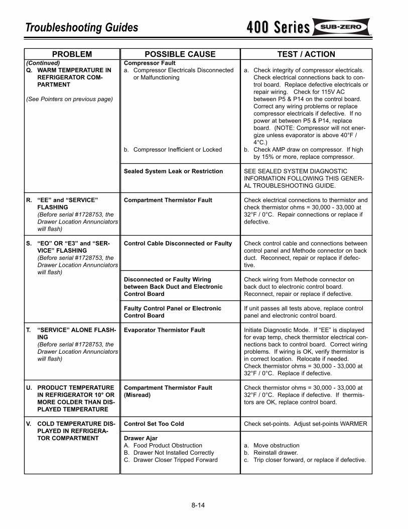
400 Series400 SeriesTroubleshooting Guides
8-14
(Continued)Q. WARM TEMPERATURE IN
REFRIGERATOR COM-PARTMENT
(See Pointers on previous page)
R. “EE” and “SERVICE”FLASHING (Before serial #1728753, theDrawer Location Annunciatorswill flash)
S. “EO” OR “E3” and “SER-VICE” FLASHING (Before serial #1728753, theDrawer Location Annunciatorswill flash)
T. “SERVICE” ALONE FLASH-ING (Before serial #1728753, theDrawer Location Annunciatorswill flash)
U. PRODUCT TEMPERATUREIN REFRIGERATOR 10° ORMORE COLDER THAN DIS-PLAYED TEMPERATURE
V. COLD TEMPERATURE DIS-PLAYED IN REFRIGERA-TOR COMPARTMENT
Compressor Fault a. Compressor Electricals Disconnected
or Malfunctioning
b. Compressor Inefficient or Locked
Sealed System Leak or Restriction
Compartment Thermistor Fault
Control Cable Disconnected or Faulty
Disconnected or Faulty Wiringbetween Back Duct and ElectronicControl Board
Faulty Control Panel or ElectronicControl Board
Evaporator Thermistor Fault
Compartment Thermistor Fault(Misread)
Control Set Too Cold
Drawer AjarA. Food Product ObstructionB. Drawer Not Installed CorrectlyC. Drawer Closer Tripped Forward
a. Check integrity of compressor electricals.Check electrical connections back to con-trol board. Replace defective electricals orrepair wiring. Check for 115V ACbetween P5 & P14 on the control board.Correct any wiring problems or replacecompressor electricals if defective. If nopower at between P5 & P14, replaceboard. (NOTE: Compressor will not ener-gize unless evaporator is above 40°F /4°C.)
b. Check AMP draw on compressor. If highby 15% or more, replace compressor.
SEE SEALED SYSTEM DIAGNOSTICINFORMATION FOLLOWING THIS GENER-AL TROUBLESHOOTING GUIDE.
Check electrical connections to thermistor andcheck thermistor ohms = 30,000 - 33,000 at32°F / 0°C. Repair connections or replace ifdefective.
Check control cable and connections betweencontrol panel and Methode connector on backduct. Reconnect, repair or replace if defec-tive.
Check wiring from Methode connector onback duct to electronic control board.Reconnect, repair or replace if defective.
If unit passes all tests above, replace controlpanel and electronic control board.
Initiate Diagnostic Mode. If “EE” is displayedfor evap temp, check thermistor electrical con-nections back to control board. Correct wiringproblems. If wiring is OK, verify thermistor isin correct location. Relocate if needed.Check thermistor ohms = 30,000 - 33,000 at32°F / 0°C. Replace if defective.
Check thermistor ohms = 30,000 - 33,000 at32°F / 0°C. Replace if defective. If thermis-tors are OK, replace control board.
Check set-points. Adjust set-points WARMER
a. Move obstructionb. Reinstall drawer.c. Trip closer forward, or replace if defective.
PROBLEM POSSIBLE CAUSE TEST / ACTION
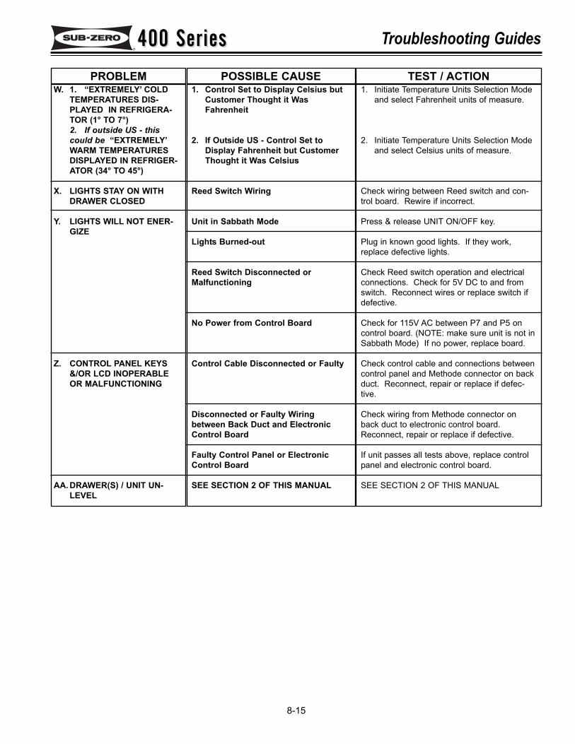
400 Series400 Series Troubleshooting Guides
8-15
W. 1. “EXTREMELY’ COLDTEMPERATURES DIS-PLAYED IN REFRIGERA-TOR (1° TO 7°)2. If outside US - thiscould be “EXTREMELY’WARM TEMPERATURESDISPLAYED IN REFRIGER-ATOR (34° TO 45°)
X. LIGHTS STAY ON WITHDRAWER CLOSED
Y. LIGHTS WILL NOT ENER-GIZE
Z. CONTROL PANEL KEYS&/OR LCD INOPERABLEOR MALFUNCTIONING
AA. DRAWER(S) / UNIT UN-LEVEL
1. Control Set to Display Celsius butCustomer Thought it WasFahrenheit
2. If Outside US - Control Set toDisplay Fahrenheit but CustomerThought it Was Celsius
Reed Switch Wiring
Unit in Sabbath Mode
Lights Burned-out
Reed Switch Disconnected orMalfunctioning
No Power from Control Board
Control Cable Disconnected or Faulty
Disconnected or Faulty Wiringbetween Back Duct and ElectronicControl Board
Faulty Control Panel or ElectronicControl Board
SEE SECTION 2 OF THIS MANUAL
1. Initiate Temperature Units Selection Modeand select Fahrenheit units of measure.
2. Initiate Temperature Units Selection Modeand select Celsius units of measure.
Check wiring between Reed switch and con-trol board. Rewire if incorrect.
Press & release UNIT ON/OFF key.
Plug in known good lights. If they work,replace defective lights.
Check Reed switch operation and electricalconnections. Check for 5V DC to and fromswitch. Reconnect wires or replace switch ifdefective.
Check for 115V AC between P7 and P5 oncontrol board. (NOTE: make sure unit is not inSabbath Mode) If no power, replace board.
Check control cable and connections betweencontrol panel and Methode connector on backduct. Reconnect, repair or replace if defec-tive.
Check wiring from Methode connector onback duct to electronic control board.Reconnect, repair or replace if defective.
If unit passes all tests above, replace controlpanel and electronic control board.
SEE SECTION 2 OF THIS MANUAL
PROBLEM POSSIBLE CAUSE TEST / ACTION
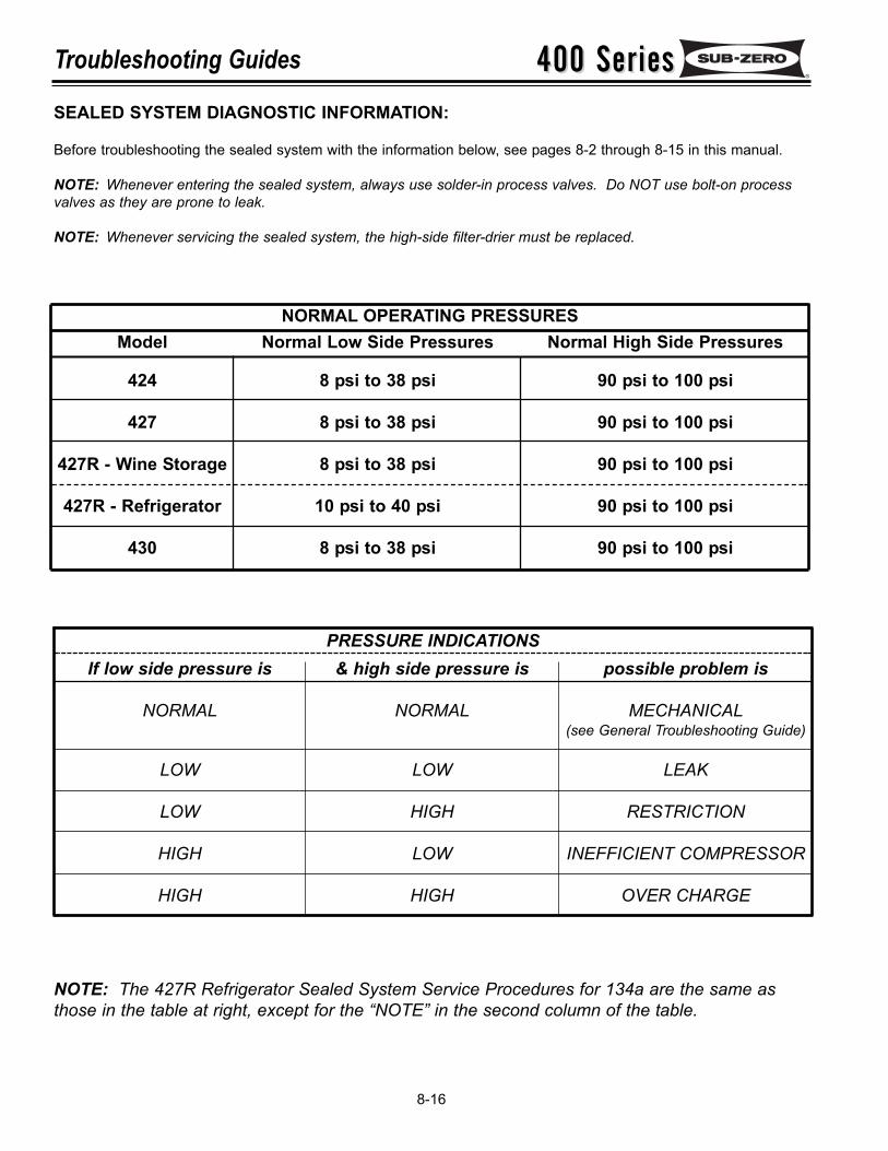
400 Series400 SeriesTroubleshooting Guides
8-16
SEALED SYSTEM DIAGNOSTIC INFORMATION:
Before troubleshooting the sealed system with the information below, see pages 8-2 through 8-15 in this manual.
NOTE: Whenever entering the sealed system, always use solder-in process valves. Do NOT use bolt-on processvalves as they are prone to leak.
NOTE: Whenever servicing the sealed system, the high-side filter-drier must be replaced.
NORMAL OPERATING PRESSURESModel
424
427
427R - Wine Storage
427R - Refrigerator
430
Normal Low Side Pressures
8 psi to 38 psi
8 psi to 38 psi
8 psi to 38 psi
10 psi to 40 psi
8 psi to 38 psi
Normal High Side Pressures
90 psi to 100 psi
90 psi to 100 psi
90 psi to 100 psi
90 psi to 100 psi
90 psi to 100 psi
PRESSURE INDICATIONSIf low side pressure is
NORMAL
LOW
LOW
HIGH
HIGH
& high side pressure is
NORMAL
LOW
HIGH
LOW
HIGH
possible problem is
MECHANICAL(see General Troubleshooting Guide)
LEAK
RESTRICTION
INEFFICIENT COMPRESSOR
OVER CHARGE
NOTE: The 427R Refrigerator Sealed System Service Procedures for 134a are the same asthose in the table at right, except for the “NOTE” in the second column of the table.
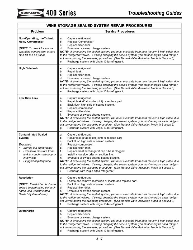
400 Series400 Series Troubleshooting Guides
8-17
WINE STORAGE SEALED SYSTEM REPAIR PROCEDURESService Procedures
a. Capture refrigerantb. Replace Compressorc. Replace filter-drierd. Evacuate or sweep charge systemNOTE: If evacuating the sealed system, you must evacuate from both the low & high sides, dueto the refrigerant valves. If sweep charging the sealed system, you must energize each refriger-ant valves during the sweeping procedure. (See Manual Valve Activation Mode in Section 3) e. Recharge system with Virgin 134a refrigerant.
a. Capture refrigerant.b. Repair leak.c. Replace filter-drier.d. Evacuate or sweep charge system.NOTE: If evacuating the sealed system, you must evacuate from both the low & high sides, dueto the refrigerant valves. If sweep charging the sealed system, you must energize each refriger-ant valves during the sweeping procedure. (See Manual Valve Activation Mode in Section 3) e. Recharge system with Virgin 134a refrigerant.
a. Capture refrigerant.b. Repair leak (if at solder joint) or replace part.c. Back flush high side of sealed system.d. Replace compressor.e. Replace filter-drier.f. Evacuate or sweep charge system.NOTE: If evacuating the sealed system, you must evacuate from both the low & high sides, dueto the refrigerant valves. If sweep charging the sealed system, you must energize each refriger-ant valves during the sweeping procedure. (See Manual Valve Activation Mode in Section 3) g. Recharge system with Virgin 134a refrigerant.
a. Capture refrigerant.b. Repair leak (if at solder joint) or replace part.c. Back flush high side of sealed system.d. Replace compressor.e. Replace filter-drier.f. Replace heat exchanger if cap tube is clogged.g. Install a low side drier on suction line.h. Evacuate or sweep charge sealed system.NOTE: If evacuating the sealed system, you must evacuate from both the low & high sides, dueto the refrigerant valves. If sweep charging the sealed system, you must energize each refriger-ant valves during the sweeping procedure. (See Manual Valve Activation Mode in Section 3) i. Recharge with Virgin 134a refrigerant.
a. Capture refrigerant.b. Locate and remove restriction or locate and replace part.c. Back flush high side of sealed system.d. Replace filter-drier.e. Evacuate or sweep charge system.NOTE: If evacuating the sealed system, you must evacuate from both the low & high sides, dueto the refrigerant valves. If sweep charging the sealed system, you must energize each refriger-ant valves during the sweeping procedure. (See Manual Valve Activation Mode in Section 3) f Recharge system with Virgin 134a refrigerant.
a. Capture refrigerant.b. Replace filter-drier.c. Evacuate or sweep charge system.NOTE: If evacuating the sealed system, you must evacuate from both the low & high sides, dueto the refrigerant valves. If sweep charging the sealed system, you must energize each refriger-ant valves during the sweeping procedure. (See Manual Valve Activation Mode in Section 3) d. Recharge system with Virgin 134a refrigerant.
.
Problem
Non-Operating, Inefficient,Noisy Compressor
(NOTE: To check for a non-operating compressor, a hardstart kit can be used)
High Side leak
Low Side Leak
Contaminated SealedSystem
Examples:> Burned out compressor> Excessive moisture from
leak in condensate loop orin low side
> Plugged capillary tube
Restriction
(NOTE: If restriction is due tosealed system being contami-nated, see ContaminatedSealed System above.)
Overcharge
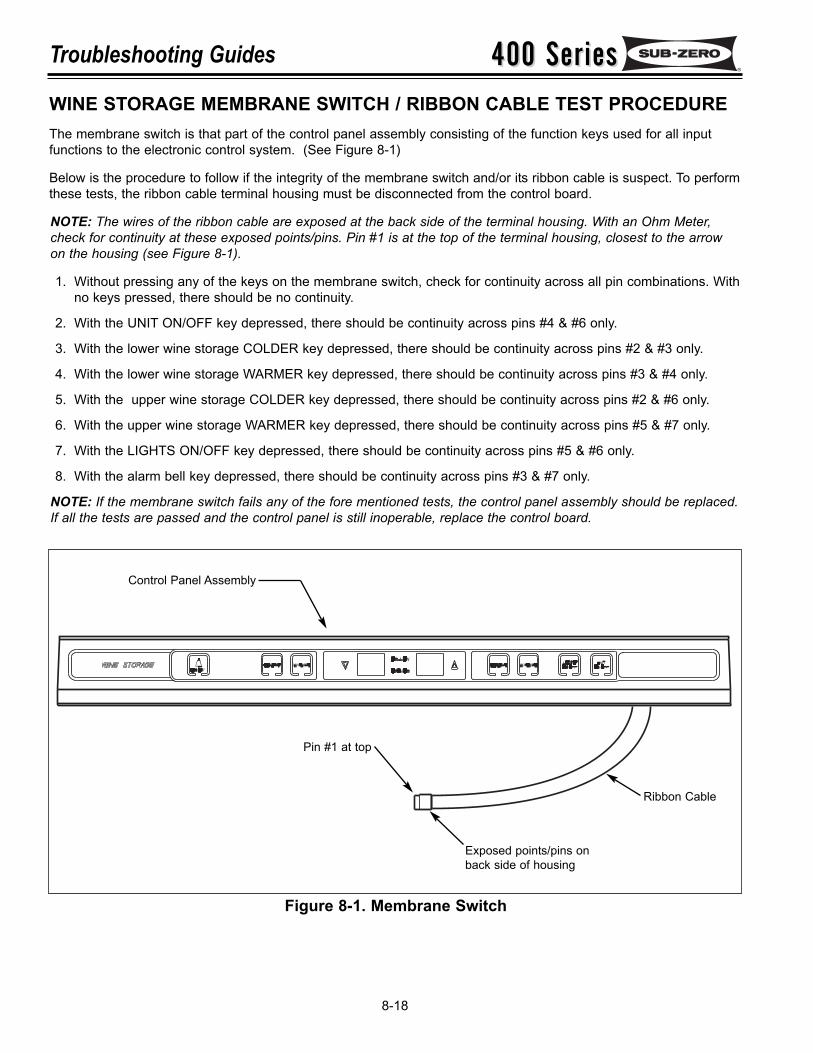
400 Series400 SeriesTroubleshooting Guides
8-18
Figure 8-1. Membrane Switch
WINE STORAGE MEMBRANE SWITCH / RIBBON CABLE TEST PROCEDUREThe membrane switch is that part of the control panel assembly consisting of the function keys used for all inputfunctions to the electronic control system. (See Figure 8-1)
Below is the procedure to follow if the integrity of the membrane switch and/or its ribbon cable is suspect. To performthese tests, the ribbon cable terminal housing must be disconnected from the control board.
NOTE: The wires of the ribbon cable are exposed at the back side of the terminal housing. With an Ohm Meter,check for continuity at these exposed points/pins. Pin #1 is at the top of the terminal housing, closest to the arrowon the housing (see Figure 8-1).
1. Without pressing any of the keys on the membrane switch, check for continuity across all pin combinations. Withno keys pressed, there should be no continuity.
2. With the UNIT ON/OFF key depressed, there should be continuity across pins #4 & #6 only.
3. With the lower wine storage COLDER key depressed, there should be continuity across pins #2 & #3 only.
4. With the lower wine storage WARMER key depressed, there should be continuity across pins #3 & #4 only.
5. With the upper wine storage COLDER key depressed, there should be continuity across pins #2 & #6 only.
6. With the upper wine storage WARMER key depressed, there should be continuity across pins #5 & #7 only.
7. With the LIGHTS ON/OFF key depressed, there should be continuity across pins #5 & #6 only.
8. With the alarm bell key depressed, there should be continuity across pins #3 & #7 only.
NOTE: If the membrane switch fails any of the fore mentioned tests, the control panel assembly should be replaced.If all the tests are passed and the control panel is still inoperable, replace the control board.
Pin #1 at top
Ribbon Cable
Exposed points/pins onback side of housing
Control Panel Assembly
400 Series400 Series Technical Data
9-1
SECTION 9
TECHNICAL DATA
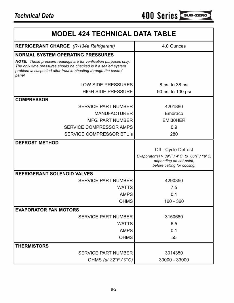
400 Series400 SeriesTechnical Data
9-2
MODEL 424 TECHNICAL DATA TABLEREFRIGERANT CHARGE (R-134a Refrigerant) 4.0 Ounces
NORMAL SYSTEM OPERATING PRESSURESNOTE: These pressure readings are for verification purposes only.The only time pressures should be checked is if a sealed systemproblem is suspected after trouble-shooting through the controlpanel.
LOW SIDE PRESSURESHIGH SIDE PRESSURE
8 psi to 38 psi90 psi to 100 psi
COMPRESSORSERVICE PART NUMBER
MANUFACTURERMFG. PART NUMBER
SERVICE COMPRESSOR AMPSSERVICE COMPRESSOR BTU’s
4201880Embraco
EMI30HER0.9280
DEFROST METHODOff - Cycle Defrost
Evaporator(s) > 39°F / 4°C to 66°F / 19°C,depending on set-point,
before calling for cooling.
REFRIGERANT SOLENOID VALVESSERVICE PART NUMBER
WATTSAMPSOHMS
42903507.50.1
160 - 360
EVAPORATOR FAN MOTORSSERVICE PART NUMBER
WATTSAMPSOHMS
31506806.50.155
THERMISTORSSERVICE PART NUMBER
OHMS (at 32°F / 0°C)3014350
30000 - 33000

400 Series400 Series Technical Data
9-3
MODEL 427 TECHNICAL DATA TABLEREFRIGERANT CHARGE (R-134a Refrigerant) 5.0 Ounces
NORMAL SYSTEM OPERATING PRESSURESNOTE: These pressure readings are for verification purposes only.The only time pressures should be checked is if a sealed systemproblem is suspected after trouble-shooting through the controlpanel.
LOW SIDE PRESSURESHIGH SIDE PRESSURE
8 psi to 38 psi90 psi to 100 psi
COMPRESSORSERVICE PART NUMBER
MANUFACTURERMFG. PART NUMBER
SERVICE COMPRESSOR AMPSSERVICE COMPRESSOR BTU’s
4201880Embraco
EMI30HER0.9280
DEFROST METHODOff - Cycle Defrost
Evaporator(s) > 39°F / 4°C to 66°F / 19°C,depending on set-point,
before calling for cooling.
REFRIGERANT SOLENOID VALVESSERVICE PART NUMBER
WATTSAMPSOHMS
42903507.50.1
160 - 360
EVAPORATOR FAN MOTORSSERVICE PART NUMBER
WATTSAMPSOHMS
31506806.50.155
THERMISTORSSERVICE PART NUMBER
OHMS (at 32°F / 0°C)3014350
30000 - 33000
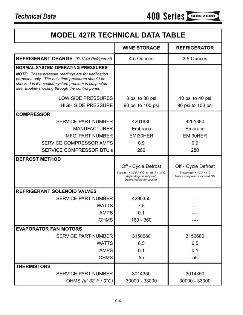
400 Series400 SeriesTechnical Data
9-4
MODEL 427R TECHNICAL DATA TABLE
REFRIGERANT CHARGE (R-134a Refrigerant) 4.5 Ounces
NORMAL SYSTEM OPERATING PRESSURESNOTE: These pressure readings are for verificationpurposes only. The only time pressures should bechecked is if a sealed system problem is suspectedafter trouble-shooting through the control panel.
LOW SIDE PRESSURESHIGH SIDE PRESSURE
8 psi to 38 psi90 psi to 100 psi
COMPRESSORSERVICE PART NUMBER
MANUFACTURERMFG. PART NUMBER
SERVICE COMPRESSOR AMPSSERVICE COMPRESSOR BTU’s
4201880Embraco
EMI30HER0.9280
DEFROST METHODOff - Cycle Defrost
Evap.(s) > 39°F / 4°C to 66°F / 19°C,depending on set-point,
before calling for cooling.
REFRIGERANT SOLENOID VALVESSERVICE PART NUMBER
WATTSAMPSOHMS
42903507.50.1
160 - 360
EVAPORATOR FAN MOTORSSERVICE PART NUMBER
WATTSAMPSOHMS
31506806.50.155
THERMISTORSSERVICE PART NUMBER
OHMS (at 32°F / 0°C)3014350
30000 - 33000
3.5 Ounces
10 psi to 40 psi90 psi to 100 psi
4201880Embraco
EMI30HER0.9280
Off - Cycle DefrostEvaporator > 40°F / 4°C
before compressor allowed ON
----------------
31506806.50.155
301435030000 - 33000
WINE STORAGE REFRIGERATOR
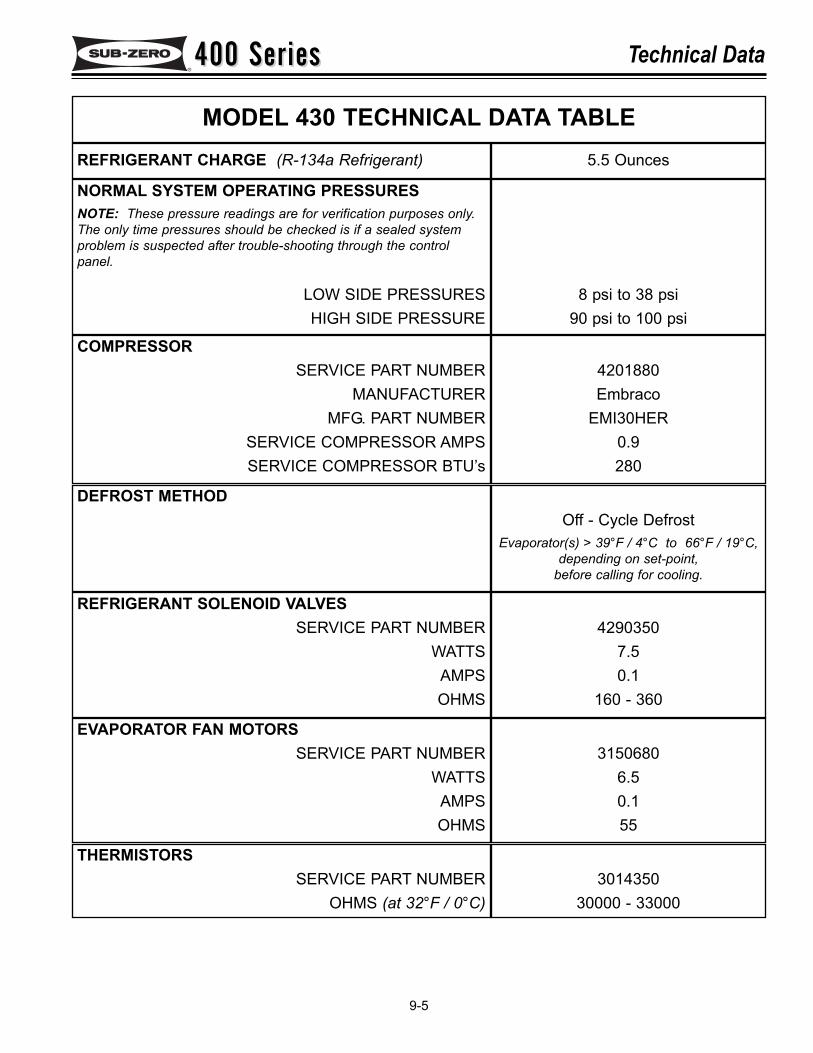
400 Series400 Series Technical Data
9-5
MODEL 430 TECHNICAL DATA TABLEREFRIGERANT CHARGE (R-134a Refrigerant) 5.5 Ounces
NORMAL SYSTEM OPERATING PRESSURESNOTE: These pressure readings are for verification purposes only.The only time pressures should be checked is if a sealed systemproblem is suspected after trouble-shooting through the controlpanel.
LOW SIDE PRESSURESHIGH SIDE PRESSURE
8 psi to 38 psi90 psi to 100 psi
COMPRESSORSERVICE PART NUMBER
MANUFACTURERMFG. PART NUMBER
SERVICE COMPRESSOR AMPSSERVICE COMPRESSOR BTU’s
4201880Embraco
EMI30HER0.9280
DEFROST METHODOff - Cycle Defrost
Evaporator(s) > 39°F / 4°C to 66°F / 19°C,depending on set-point,
before calling for cooling.
REFRIGERANT SOLENOID VALVESSERVICE PART NUMBER
WATTSAMPSOHMS
42903507.50.1
160 - 360
EVAPORATOR FAN MOTORSSERVICE PART NUMBER
WATTSAMPSOHMS
31506806.50.155
THERMISTORSSERVICE PART NUMBER
OHMS (at 32°F / 0°C)3014350
30000 - 33000

400 Series400 SeriesTechnical Data Notes
9-6
400 Series400 Series Wiring Diagrams & Schematics
10-1
SECTION 10
WIRING DIAGRAMS &SCHEMATICS
NOTE: Due to our continuous improvement program,it is recommended to always use the wiring diagram& schematic supplied with the unit, located in theenvelope in the compressor area. This section is forreferencing prior to servicing or if the wiring diagram& schematic are missing from the unit.

400 Series400 SeriesWiring Diagrams & Schematics
10-2
BLU
E W
/ W
HIT
E
BLU
E W
/ W
HIT
E
BLU
E W
/ R
ED
OR
AN
GE
W/ R
ED
PLAIN
RIBBED
1 BLACK
2 WHITE
GRAY
WHITE
WHITE
GRAY
BLUE
WHITE
WHITE
1 B
LU
E
2 W
HIT
E
2 W
HIT
E
1 P
INK
1 W
HIT
E W
/ R
ED
2 W
HIT
E W
/ B
LU
E
3 G
RA
Y W
/ W
HIT
E
5 Y
ELLO
W
6 B
LU
E
8 P
INK
10 W
HIT
E
12 G
RE
EN
12345678910
11
12
6 5 4 3 2 178
1 B
LU
E W
/ R
ED
2 O
RA
NG
E W
/ R
ED
3 B
LU
E W
/ Y
ELLO
W
4 O
RA
NG
E W
/ Y
ELLO
W
YELLOW
RED
BROWN
ORANGE
GR
AY
BLA
CK
RE
D
OR
AN
GE
WH
ITE
WH
ITE
GR
EE
N
ORANGE
7 O
RA
NG
E
1 RED
2 WHITE
3 GREEN
2 WHITE
1 GRAY
3 GREEN
OR
AN
GE
W/ R
ED
BLU
E W
/ R
ED
BLU
E W
/ W
HIT
E
BLU
E W
/ W
HIT
E
OR
AN
GE
W/ Y
ELLO
W
BLU
E W
/ Y
ELLO
W
BLU
E W
/ B
LA
CK
BLU
E W
/ B
LA
CK
BLUE W/ BLACK
BLUE W/ BLACK
OR
AN
GE
W/ Y
ELLO
W
BLU
E W
/ Y
ELLO
W
OR
AN
GE
WH
ITE
WH
ITE
GR
EE
N
RE
D
1 GREEN
2 WHITE
3 RED
WH
ITE
OR
AN
GE
POWER
SUPPLY CORD
CONDENSER
FAN MOTOR
COMPRESSOR
TESTER
FAN
SWITCH
LIGHT
SWITCH
ALARM
SENSOR
LOWER
COMPARTMENT
LOWER FAN
MOTOR
WINE
CONTROL
BOARD
SENSOR
COMPARTMENT
UPPER
SENSOR
UPPER EVAP.
LIGHT TUBE
UPPER FAN
MOTOR
UPPER
SOLENOID SOLENOID
LOWER
SENSOR
LOWER
EVAP
UP
PE
R C
OM
PA
RT
ME
NT
UP
PE
R C
OM
PA
RT
ME
NT
LO
WE
R C
OM
PA
RT
ME
NT
LO
WE
R C
OM
PA
RT
ME
NT
BR
OW
N
4 OPEN
400 S
ER
IES
CO
NT
RO
L B
OA
RD
SU
MM
AR
Y/ L
AY
OU
T
L1L2
GREEN
HEATSHRINK
CO
OL
S U
PP
ER
CO
MP
AR
TM
EN
TP
8U
PP
ER
SO
LE
NO
ID V
AL
VE
12
0 V
OL
T C
IRC
UIT
S
E3
CIR
CU
IT
E2
E1
P1
2J3
P9
P1
1P
10
LIG
HT
S
DE
SC
RIP
TIO
N
CO
MP
RE
SS
OR
PO
WE
R IN
GR
OU
ND
EM
PT
Y
EM
PT
YN
EU
TR
AL
PO
WE
RS
LIG
HT
S
EA
RT
H G
RO
UN
D
FU
NC
TIO
N
PO
WE
R IN
TO
BO
AR
D
NE
UT
RA
L I
NT
O B
OA
RD
PO
WE
RS
CO
MP
RE
SS
OR
LO
WE
R S
OL
EN
OID
VA
LV
EL
IGH
TS
OV
ER
RID
E
EV
AP
OR
AT
OR
FA
NS
P5
P6
P7 P4
EM
PT
Y
ON
WH
EN
LIG
HT
S O
N 1
00
%C
OO
LS
LO
WE
R C
OM
PA
RT
ME
NT
PO
WE
RS
EV
AP
OR
AT
OR
FA
NS
HEATSHRINK
UP
PE
R C
AB
INE
TS
EN
SE
S T
EM
PE
RA
TU
RE
BL
UE
/BL
AC
KP
INK
-This wiring information is provided for use by qualified
service personnel only.
-Disconnect appliance from electrical supply before
beginning service.
-Be sure all grounding devices are connected when
service is complete.
-Failure to observe the above warnings may result in
severe electrical shock.
SE
NS
ES
TE
MP
ER
AT
UR
ES
EN
SE
S T
EM
PE
RA
TU
RE
SE
NS
ES
TE
MP
ER
AT
UR
E
FO
R H
OM
E A
LA
RM
SF
OR
HO
ME
AL
AR
MS
FO
R H
OM
E A
LA
RM
S
FU
NC
TIO
N
HEATSHRINK
E3 E1
E2
TH
ER
MIS
TE
R C
IRC
UIT
S
AL
AR
M C
IRC
UIT
UP
PE
R C
AB
INE
TL
OW
ER
CA
BIN
ET
LO
WE
R C
AB
INE
T
AL
AR
M C
IRC
UIT
-N
OR
MA
LL
Y O
PE
NA
LA
RM
CIR
CU
IT-N
OR
MA
LL
Y C
LO
SE
DA
LA
RM
CIR
CU
IT-C
OM
MO
N
LO
W V
OL
TA
GE
CIR
CU
ITS
HEATSHRINK
BR
OW
N
CO
LO
R
GR
AY
BL
AC
K
WH
ITE
GR
EE
N
P2
CIR
CU
IT
J3
P1
J2
P3
P3
P2
P1
DE
SC
RIP
TIO
N
HEATSHRINK
BL
UE
/BL
AC
KB
LU
E/W
HIT
EB
LU
E/W
HIT
E
GR
AY
/WH
TW
HT
/BL
UE
WH
T/R
ED
CO
LO
R
SE
NS
ES
TE
MP
ER
AT
UR
ES
EN
SE
S T
EM
PE
RA
TU
RE
SE
NS
ES
TE
MP
ER
AT
UR
ES
EN
SE
S T
EM
PE
RA
TU
RE
UP
PE
R E
VA
PO
RA
TO
RU
PP
ER
EV
AP
OR
AT
OR
LO
WE
R E
VA
PO
RA
TO
RL
OW
ER
EV
AP
OR
AT
OR
YE
LL
OW
OR
AN
GE
BL
UE
P7
P6
P5
P4
P8
BL
UE
/YE
LL
OW
OR
AN
GE
/YE
LL
OR
AN
GE
/RE
DB
LU
E/R
ED
PA
RT
NU
MB
ER
37
56
36
0 -
Re
v.
C
WIRING DIAGRAMMODEL 424
(Prior to Serial #1944319)
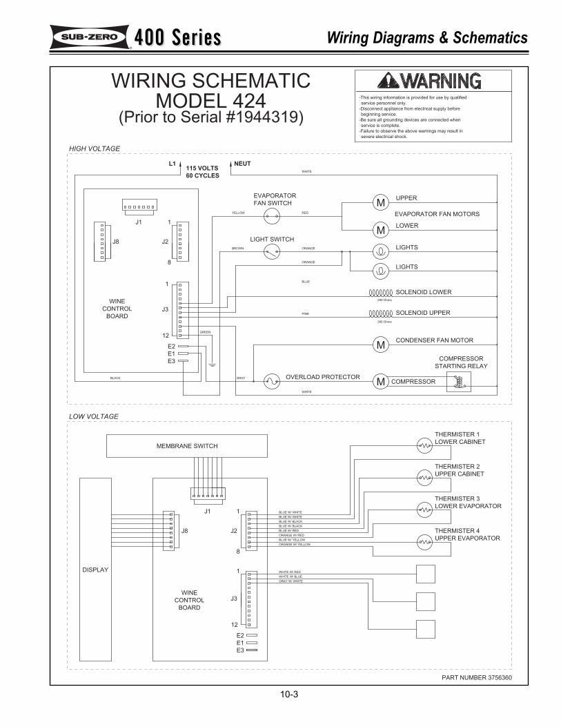
400 Series400 Series Wiring Diagrams & Schematics
10-3
severe electrical shock.
-Failure to observe the above warnings may result in
service is complete.
-Be sure all grounding devices are connected when
beginning service.
-Disconnect appliance from electrical supply before
service personnel only.
-This wiring information is provided for use by qualified
PART NUMBER 3756360
E2
E3
E1
12
MUPPER
WHITE
NEUT
EVAPORATOR
FAN SWITCH
M
LIGHTS
LOWER
295 Ohms
LIGHTS
SOLENOID LOWER
EVAPORATOR FAN MOTORS
COMPRESSOR
295 Ohms
M
M COMPRESSOR
CONDENSER FAN MOTOR
SOLENOID UPPER
STARTING RELAY
RED
ORANGE
ORANGE
BLUE
BROWN
YELLOW
LIGHT SWITCH
PINK
WHITE
GRAY OVERLOAD PROTECTOR
L1
1
J2
J1
8
1
J8
WINE
E2
E1
12
E3
BLACK
BOARD
CONTROL J3
GREEN
115 VOLTS
60 CYCLES
LOW VOLTAGE
8
1
J8
J1
J2
J3
1
BOARD
CONTROL
WINE
DISPLAY
MEMBRANE SWITCH
THERMISTER 4
UPPER EVAPORATOR
THERMISTER 3
LOWER EVAPORATOR
THERMISTER 2
UPPER CABINET
LOWER CABINET
THERMISTER 1
GRAY W/ WHITE
WHITE W/ BLUE
WHITE W/ RED
ORANGE W/ YELLOW
BLUE W/ YELLOW
ORANGE W/ RED
BLUE W/ RED
BLUE W/ BLACK
BLUE W/ BLACK
BLUE W/ WHITE
BLUE W/ WHITE
HIGH VOLTAGE
WIRING SCHEMATICMODEL 424
(Prior to Serial #1944319)
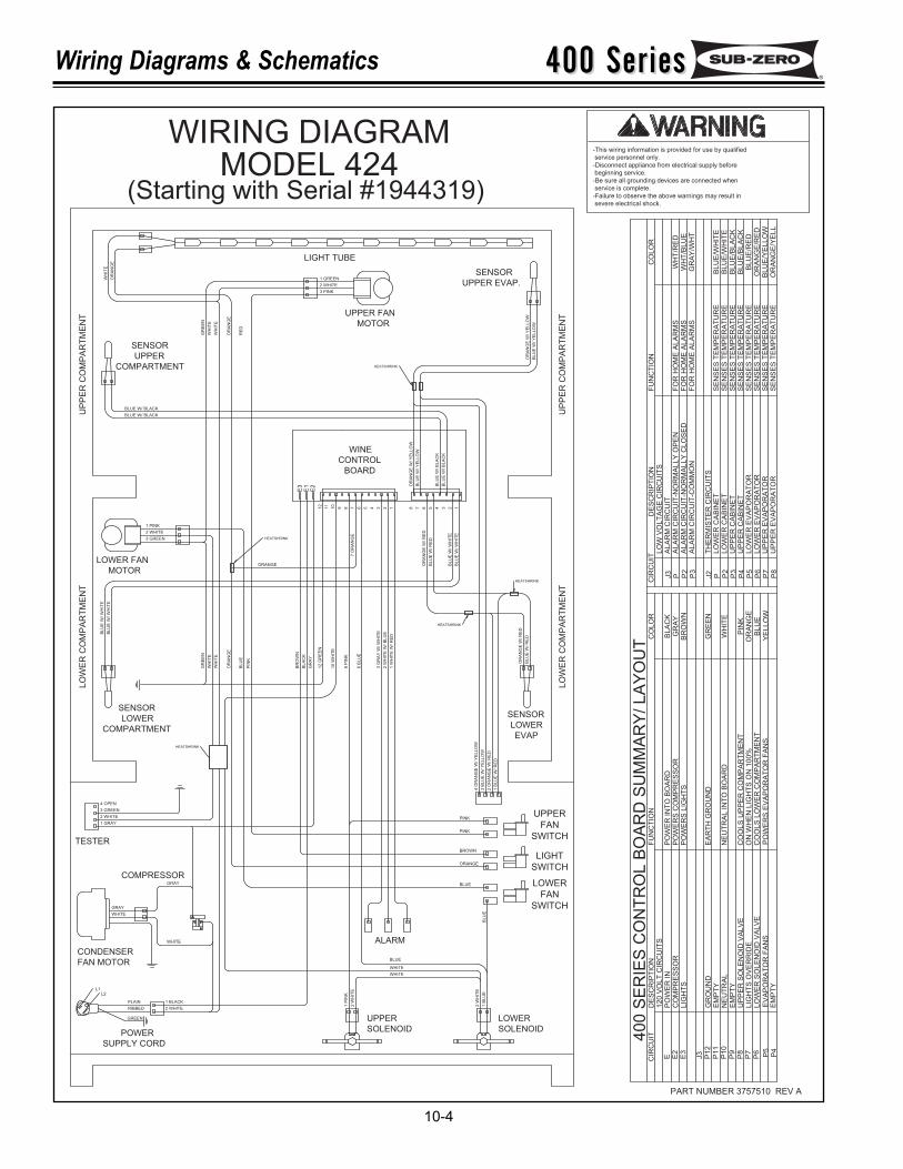
400 Series400 SeriesWiring Diagrams & Schematics
10-4
PART NUMBER 3757510 REV A
GREEN
BL
UE
W/ W
HIT
E
BL
UE
W/ W
HIT
E
BL
UE
W/
RE
D
OR
AN
GE
W/ R
ED
PLAIN
RIBBED
1 BLACK
2 WHITE
GRAY
WHITE
WHITE
GRAY
BLUE
WHITE
WHITE
1 B
LU
E
2 W
HIT
E
2 W
HIT
E
1 P
INK
1 W
HIT
E W
/ R
ED
2 W
HIT
E W
/ B
LU
E
3 G
RA
Y W
/ W
HIT
E
6 B
LU
E
8 P
INK
10
WH
ITE
12
GR
EE
N
12345678910
11
12
6 5 4 3 2 178
1 B
LU
E W
/ R
ED
2 O
RA
NG
E W
/ R
ED
3 B
LU
E W
/ Y
EL
LO
W
4 O
RA
NG
E W
/ Y
ELLO
W
PINK
PINK
BROWN
ORANGE
GR
AY
BL
AC
K
PIN
K
OR
AN
GE
WH
ITE
WH
ITE
GR
EE
N
ORANGE
7 O
RA
NG
E
1 PINK
2 WHITE
3 GREEN
2 WHITE
1 GRAY
3 GREEN
OR
AN
GE
W/ R
ED
BL
UE
W/
RE
D
BL
UE
W/ W
HIT
E
BL
UE
W/ W
HIT
E
OR
AN
GE
W/ Y
ELLO
W
BL
UE
W/ Y
EL
LO
W
BL
UE
W/
BL
AC
K
BL
UE
W/
BL
AC
K
BLUE W/ BLACK
BLUE W/ BLACK
OR
AN
GE
W/ Y
EL
LO
W
BL
UE
W/
YE
LL
OW
OR
AN
GE
WH
ITE
WH
ITE
GR
EE
N
RE
D
1 GREEN
2 WHITE
3 PINK
WH
ITE
OR
AN
GE
POWER
SUPPLY CORD
CONDENSER
FAN MOTOR
COMPRESSOR
TESTER
ALARM
SENSOR
LOWER
COMPARTMENT
LOWER FAN
MOTOR
WINE
CONTROL
BOARD
SENSOR
COMPARTMENT
UPPER
SENSOR
UPPER EVAP.
LIGHT TUBE
UPPER FAN
MOTOR
UPPER
SOLENOID SOLENOID
LOWER
L2L1
UP
PE
R C
OM
PA
RT
ME
NT
UP
PE
R C
OM
PA
RT
ME
NT
LO
WE
R C
OM
PA
RT
ME
NT
LO
WE
R C
OM
PA
RT
ME
NT
HEATSHRINK
HEATSHRINK
HEATSHRINK
HEATSHRINK
HEATSHRINK
BR
OW
N
4 OPEN
BLUE
BL
UE
UPPER
FAN
SWITCH
LIGHT
SWITCH
LOWER
FAN
SWITCH
BL
UE
EV
AP
OR
AT
OR
FA
NS
LIG
HT
S O
VE
RR
IDE
LO
WE
R S
OLE
NO
ID V
ALV
E
120 V
OLT
CIR
CU
ITS
UP
PE
R S
OLE
NO
ID V
ALV
E
40
0 S
ER
IES
CO
NT
RO
L B
OA
RD
SU
MM
AR
Y/ L
AY
OU
TC
IRC
UIT
E E2
PO
WE
R IN
CO
MP
RE
SS
OR
DE
SC
RIP
TIO
N
P10
P1
2J3
P11
P8
P9
P7
P6 P4
P5
NE
UT
RA
LE
MP
TY
EM
PT
YG
RO
UN
D
EM
PT
YP
OW
ER
S E
VA
PO
RA
TO
R F
AN
S
CO
OLS
UP
PE
R C
OM
PA
RT
ME
NT
CO
OLS
LO
WE
R C
OM
PA
RT
ME
NT
PO
WE
RS
CO
MP
RE
SS
OR
ON
WH
EN
LIG
HT
S O
N 1
00%
NE
UT
RA
L IN
TO
BO
AR
D
PO
WE
R IN
TO
BO
AR
D
FU
NC
TIO
N
EA
RT
H G
RO
UN
D
BLA
CK
GR
AY
CO
LO
R
BLU
EO
RA
NG
EP
INK
GR
EE
N
WH
ITE
YE
LLO
W
E3
LIG
HT
SP
OW
ER
S L
IGH
TS
BR
OW
N
DE
SC
RIP
TIO
NC
IRC
UIT
FU
NC
TIO
NC
OLO
RLO
W V
OLT
AG
E C
IRC
UIT
S
ALA
RM
CIR
CU
IT-C
OM
MO
N
ALA
RM
CIR
CU
IT-N
OR
MA
LLY
OP
EN
FO
R H
OM
E A
LA
RM
SF
OR
HO
ME
ALA
RM
SF
OR
HO
ME
ALA
RM
SW
HT
/RE
DW
HT
/BLU
EG
RA
Y/W
HT
P P2
P3
J3
J2
PLO
WE
R C
AB
INE
TS
EN
SE
S T
EM
PE
RA
TU
RE
BLU
E/W
HIT
EB
LU
E/W
HIT
ELO
WE
R C
AB
INE
TP
2B
LU
E/B
LA
CK
UP
PE
R C
AB
INE
TP
3B
LU
E/B
LA
CK
UP
PE
R C
AB
INE
TP
4B
LU
E/R
ED
LO
WE
R E
VA
PO
RA
TO
RP
5O
RA
NG
E/R
ED
LO
WE
R E
VA
PO
RA
TO
RP
6
OR
AN
GE
/YE
LL
UP
PE
R E
VA
PO
RA
TO
RP
8
BLU
E/Y
ELLO
WU
PP
ER
EV
AP
OR
AT
OR
P7
ALA
RM
CIR
CU
IT
TH
ER
MIS
TE
R C
IRC
UIT
S
ALA
RM
CIR
CU
IT-N
OR
MA
LLY
CLO
SE
D
SE
NS
ES
TE
MP
ER
AT
UR
ES
EN
SE
S T
EM
PE
RA
TU
RE
SE
NS
ES
TE
MP
ER
AT
UR
ES
EN
SE
S T
EM
PE
RA
TU
RE
SE
NS
ES
TE
MP
ER
AT
UR
ES
EN
SE
S T
EM
PE
RA
TU
RE
SE
NS
ES
TE
MP
ER
AT
UR
E
E
2
SENSOR
LOWER
EVAP
E
1
E3
-This wiring information is provided for use by qualified
service personnel only.
-Disconnect appliance from electrical supply before
beginning service.
-Be sure all grounding devices are connected when
service is complete.
-Failure to observe the above warnings may result in
severe electrical shock.
WIRING DIAGRAMMODEL 424
(Starting with Serial #1944319)
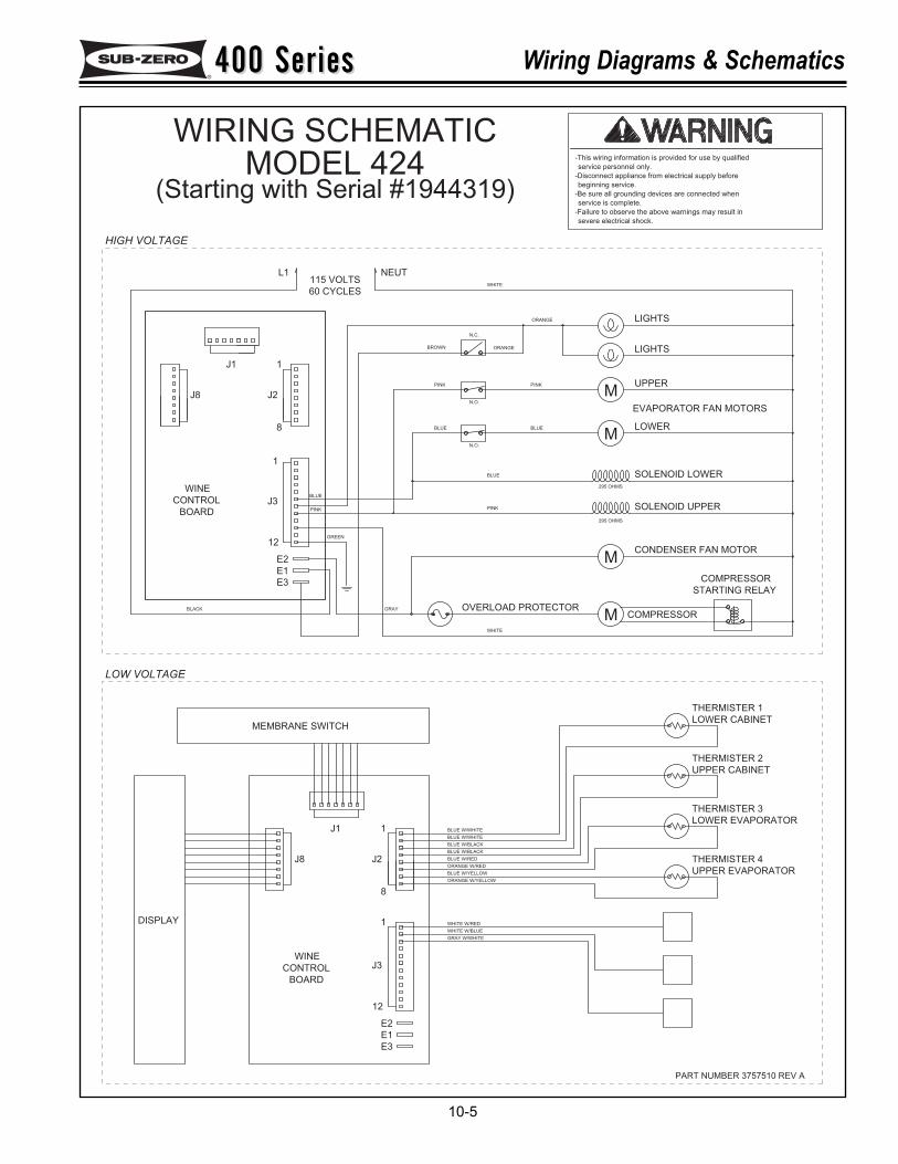
400 Series400 Series Wiring Diagrams & Schematics
10-5
PART NUMBER 3757510 REV A
BLUE W/WHITE
BLUE W/WHITE
BLUE W/BLACK
BLUE W/BLACK
BLUE W/RED
ORANGE W/RED
BLUE W/YELLOW
ORANGE W/YELLOW
WHITE W/RED
WHITE W/BLUE
GRAY W/WHITE
THERMISTER 1
LOWER CABINET
UPPER CABINET
THERMISTER 2
LOWER EVAPORATOR
THERMISTER 3
UPPER EVAPORATOR
THERMISTER 4
MEMBRANE SWITCH
DISPLAY
WINE
CONTROL
BOARD
1
J3
J2
J1
J8
1
8
60 CYCLES
115 VOLTS
GREEN
J3CONTROL
BOARD
BLACK
E3
12
E1
E2
WINE
J8
1
8
J1
J2
1
L1
OVERLOAD PROTECTORGRAY
WHITE
PINK
PINK
BROWN
BLUE
ORANGE
ORANGE
PINK
STARTING RELAY
SOLENOID UPPER
CONDENSER FAN MOTOR
COMPRESSOR
295 OHMS
COMPRESSOR
EVAPORATOR FAN MOTORS
SOLENOID LOWER
LIGHTS
295 OHMS
LOWER
LIGHTS
NEUTWHITE
UPPER
12
E1
E3
E2
BLUE BLUE
N.O.
N.O.
N.C.
PINK
BLUE
M
M
M
M
severe electrical shock.
-Failure to observe the above warnings may result in
service is complete.
-Be sure all grounding devices are connected when
beginning service.
-Disconnect appliance from electrical supply before
service personnel only.
-This wiring information is provided for use by qualified
LOW VOLTAGE
HIGH VOLTAGE
WIRING SCHEMATICMODEL 424
(Starting with Serial #1944319)
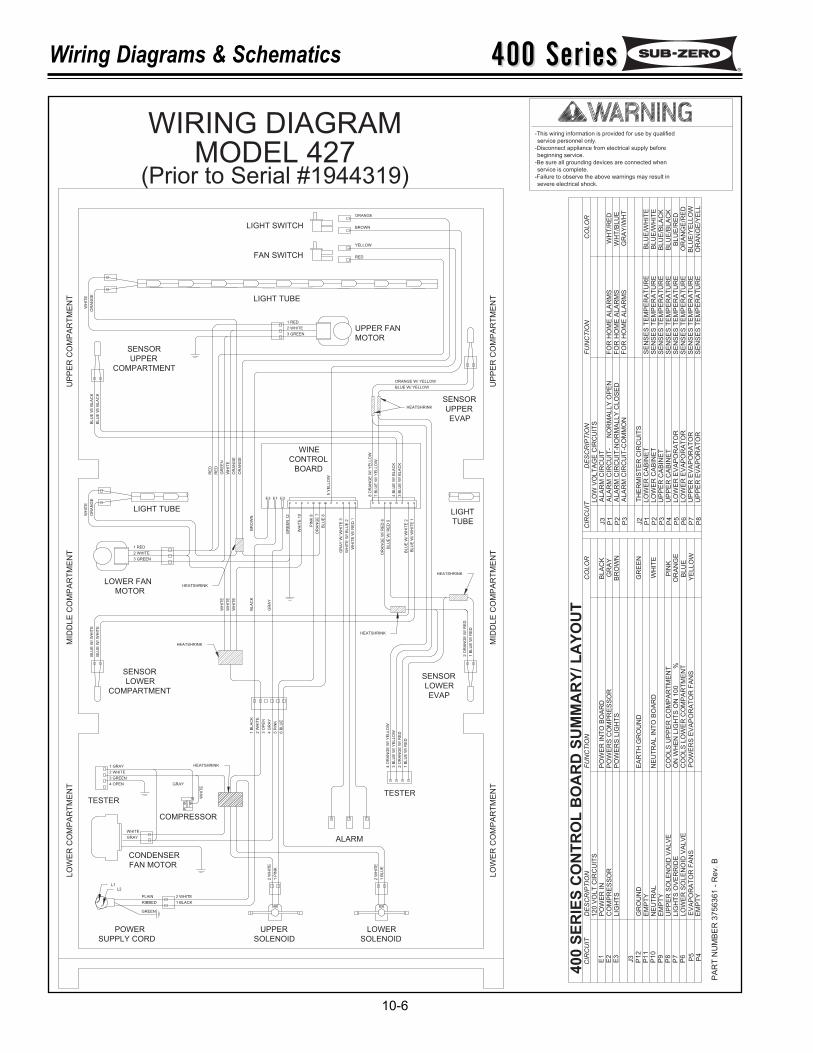
400 Series400 SeriesWiring Diagrams & Schematics
10-6
RIBBED
PLAIN
1 BLACK
2 WHITE
GRAY
WHITE
2 WHITE
3 GREEN
1 RED
LIGHT TUBE
LIGHT SWITCH
FAN SWITCH
LIGHT TUBE
1 RED
2 WHITE
3 GREENUPPER FAN
MOTOR
SENSOR
UPPER
EVAP
COMPARTMENT
SENSOR
UPPER
LIGHT
TUBE
WINE
CONTROL
BOARD
LOWER FAN
MOTOR
SENSOR
LOWER
COMPARTMENT
SENSOR
LOWER
EVAP
TESTERTESTER
COMPRESSOR
CONDENSER
FAN MOTOR
POWER
SUPPLY CORD
UPPER
SOLENOID
LOWER
SOLENOID
ALARM
ORANGE
BROWN
YELLOW
RED
WH
ITE
OR
AN
GE
ORANGE W/ YELLOW
BLUE W/ YELLOW
8 O
RA
NG
E W
/ Y
ELLO
W
7 B
LU
E W
/ Y
ELLO
W
4 B
LU
E W
/ B
LA
CK
3 B
LU
E W
/ B
LA
CK
OR
AN
GE
W/ R
ED
6
BLU
E W
/ R
ED
5
BLU
E W
/ W
HIT
E 2
BLU
E W
/ W
HIT
E 1
WH
ITE
W/ R
ED
1
WH
ITE
W/ B
LU
E 2
GR
AY
W/ W
HIT
E 3
BLU
E 6
OR
AN
GE
7
PIN
K 8
WH
ITE
10
GR
EE
N 1
2
5 Y
ELLO
W
BLU
E W
/ B
LA
CK
BLU
E W
/ B
LA
CK
OR
AN
GE
WH
ITE
RE
D
RE
D
GR
EE
N
WH
ITE
OR
AN
GE
OR
AN
GE
WH
ITE
WH
ITE
WH
ITE
BLA
CK
GR
AY
BLU
E W
/ W
HIT
E
BLU
E W
/ W
HIT
E
3 B
LU
E W
/ Y
ELLO
W
4 O
RA
NG
E W
/ Y
ELLO
W
2 O
RA
NG
E W
/ R
ED
1 B
LU
E W
/ R
ED
2 O
RA
NG
E W
/ R
ED
1 B
LU
E W
/ R
ED
3 GREEN
4 OPEN
2 W
HIT
E
1 B
LU
E
1 P
INK
2 W
HIT
E
1 B
LA
CK
2 W
HIT
E
4 G
RA
Y
5 P
INK
6 B
LU
E
3 O
PE
N
GRAY
WH
ITE
UP
PE
R C
OM
PA
RT
ME
NT
UP
PE
R C
OM
PA
RT
ME
NT
MID
DL
E C
OM
PA
RT
ME
NT
MID
DL
E C
OM
PA
RT
ME
NT
LO
WE
R C
OM
PA
RT
ME
NT
LO
WE
R C
OM
PA
RT
ME
NT
E2
BR
OW
N
2 WHITE
1 GRAY
E1E3
YE
LLO
W
PIN
KO
RA
NG
EB
LU
E
WH
ITE
GR
EE
N
CO
LO
R
GR
AY
BLA
CK
BR
OW
N
40
0 S
ER
IES
CO
NT
RO
L B
OA
RD
SU
MM
AR
Y/
LA
YO
UT
L2
GREEN
L1
HEATSHRINK
HEATSHRINK
HEATSHRINK
LIG
HT
S O
VE
RR
IDE
ON
WH
EN
LIG
HT
S O
N 1
00
%P
7
PA
RT
NU
MB
ER
37
56
36
1 -
Re
v. B
P11
P1
0
P1
2
CIR
CU
IT
E1
E3
E2
J3
P8
P9
UP
PE
R S
OLE
NO
ID V
ALV
E
NE
UT
RA
L
GR
OU
ND
PO
WE
R IN
DE
SC
RIP
TIO
N
CO
MP
RE
SS
OR
120 V
OLT
CIR
CU
ITS
LIG
HT
S
EM
PT
Y
EM
PT
Y
HEATSHRINK
HEATSHRINK
NE
UT
RA
L IN
TO
BO
AR
D
CO
OLS
UP
PE
R C
OM
PA
RT
ME
NT
PO
WE
R IN
TO
BO
AR
DP
OW
ER
S C
OM
PR
ES
SO
R
EA
RT
H G
RO
UN
D
FU
NC
TIO
N
PO
WE
RS
LIG
HT
S
P5
P4
P6
LO
WE
R S
OLE
NO
ID V
ALV
E
EV
AP
OR
AT
OR
FA
NS
EM
PT
Y
CO
OLS
LO
WE
R C
OM
PA
RT
ME
NT
PO
WE
RS
EV
AP
OR
AT
OR
FA
NS
BLU
E/R
ED
LO
WE
R E
VA
PO
RA
TO
RS
EN
SE
S T
EM
PE
RA
TU
RE
P5
-This wiring information is provided for use by qualified
service personnel only.
-Disconnect appliance from electrical supply before
beginning service.
-Be sure all grounding devices are connected when
service is complete.
-Failure to observe the above warnings may result in
severe electrical shock.
SE
NS
ES
TE
MP
ER
AT
UR
ES
EN
SE
S T
EM
PE
RA
TU
RE
SE
NS
ES
TE
MP
ER
AT
UR
ES
EN
SE
S T
EM
PE
RA
TU
RE
FO
R H
OM
E A
LA
RM
S
FO
R H
OM
E A
LA
RM
SF
OR
HO
ME
ALA
RM
S
HEATSHRINK
TH
ER
MIS
TE
R C
IRC
UIT
S
ALA
RM
CIR
CU
IT-C
OM
MO
N
DE
SC
RIP
TIO
N
ALA
RM
CIR
CU
IT-
NO
RM
ALLY
OP
EN
LO
W V
OLT
AG
E C
IRC
UIT
S
ALA
RM
CIR
CU
IT-N
OR
MA
LLY
CLO
SE
D
UP
PE
R C
AB
INE
T
LO
WE
R C
AB
INE
TLO
WE
R C
AB
INE
T
UP
PE
R C
AB
INE
T
ALA
RM
CIR
CU
IT
P3
CIR
CU
IT
J3
P2
P1
P1
J2
P4
P3
P2
FU
NC
TIO
N
BLU
E/B
LA
CK
BLU
E/B
LA
CK
BLU
E/W
HIT
EB
LU
E/W
HIT
E
GR
AY
/WH
T
WH
T/R
ED
WH
T/B
LU
E
CO
LO
R
SE
NS
ES
TE
MP
ER
AT
UR
ES
EN
SE
S T
EM
PE
RA
TU
RE
SE
NS
ES
TE
MP
ER
AT
UR
EU
PP
ER
EV
AP
OR
AT
OR
UP
PE
R E
VA
PO
RA
TO
R
LO
WE
R E
VA
PO
RA
TO
R
P7
P8
P6
BLU
E/Y
ELLO
WO
RA
NG
E/Y
ELL
OR
AN
GE
/RE
D
WIRING DIAGRAMMODEL 427
(Prior to Serial #1944319)
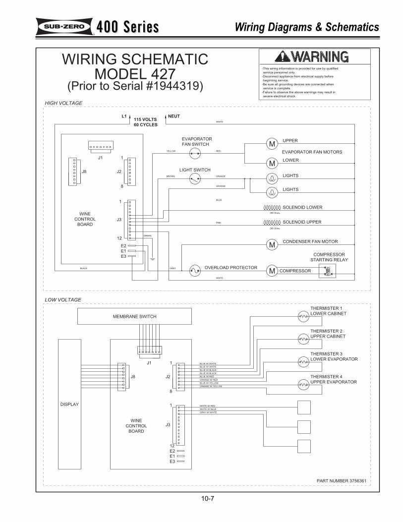
400 Series400 Series Wiring Diagrams & Schematics
10-7
severe electrical shock.
-Failure to observe the above warnings may result in
service is complete.
-Be sure all grounding devices are connected when
beginning service.
-Disconnect appliance from electrical supply before
service personnel only.
-This wiring information is provided for use by qualified
PART NUMBER 3756361
E3
E1
E2
MUPPER
WHITE
NEUT
EVAPORATOR
FAN SWITCH
M
LIGHTS
LOWER
295 Ohms
LIGHTS
SOLENOID LOWER
EVAPORATOR FAN MOTORS
COMPRESSOR
295 Ohms
M
M COMPRESSOR
CONDENSER FAN MOTOR
SOLENOID UPPER
STARTING RELAY
RED
ORANGE
ORANGE
BLUE
BROWN
YELLOW
LIGHT SWITCH
PINK
WHITE
GRAY OVERLOAD PROTECTOR
L1
1
J2
J1
8
1
J8
WINE
E2
E1
12
E3
BLACK
BOARD
CONTROL J3
GREEN
115 VOLTS
60 CYCLES
LOWER CABINET
THERMISTER 1
LOWER EVAPORATOR
THERMISTER 3
UPPER CABINET
THERMISTER 2
UPPER EVAPORATOR
THERMISTER 4BLUE W/ RED
BLUE W/ BLACK
BLUE W/ BLACK
BLUE W/ WHITE
BLUE W/ WHITE1J1
ORANGE W/ RED
GRAY W/ WHITE
WHITE W/ BLUE
WHITE W/ RED
BLUE W/ YELLOW
ORANGE W/ YELLOW
8
1
WINE
12
BOARD
J3CONTROL
J2J8
DISPLAY
MEMBRANE SWITCH
LOW VOLTAGE
HIGH VOLTAGE
WIRING SCHEMATICMODEL 427
(Prior to Serial #1944319)
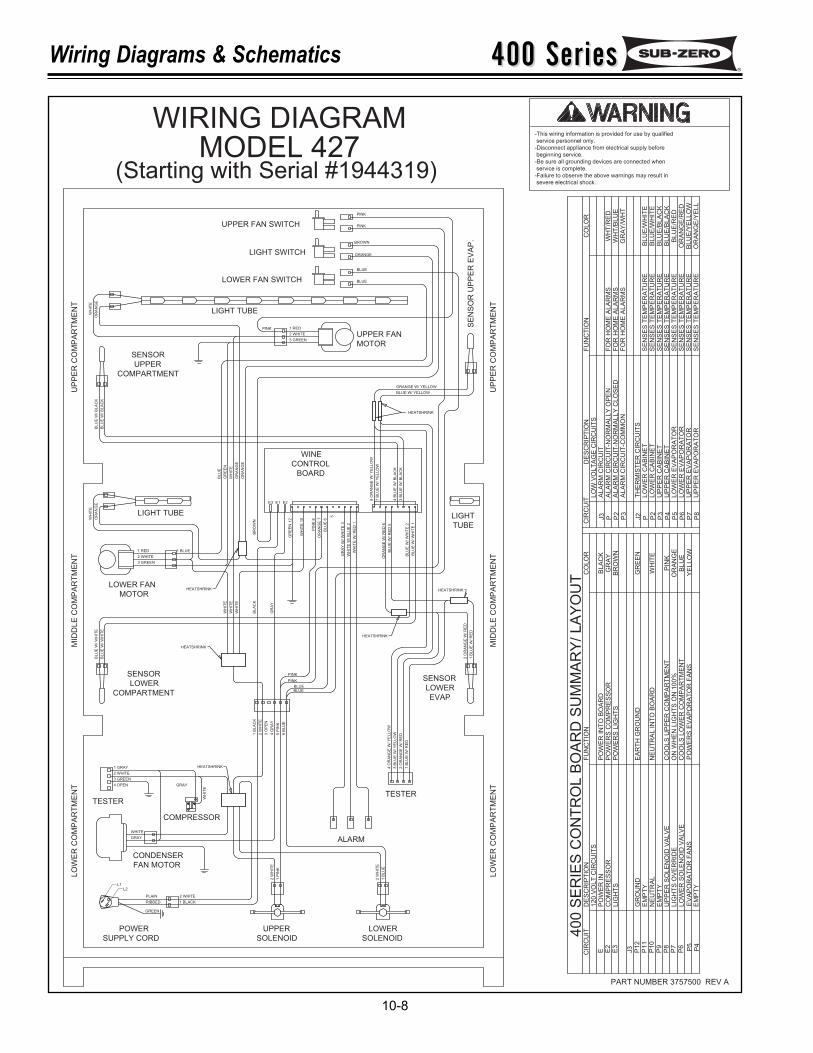
400 Series400 SeriesWiring Diagrams & Schematics
10-8
PART NUMBER 3757500 REV A
L1L2
RIBBED
GREEN
PLAIN
1 BLACK
2 WHITE
GRAY
WHITE
2 WHITE
3 GREEN
1 RED
LIGHT TUBE
LIGHT SWITCH
LOWER FAN SWITCH
LIGHT TUBE
1 RED
2 WHITE
3 GREENUPPER FAN
MOTOR
COMPARTMENT
SENSOR
UPPER
LIGHT
TUBE
WINE
CONTROL
BOARD
LOWER FAN
MOTOR
SENSOR
LOWER
COMPARTMENT
SENSOR
LOWER
EVAP
TESTERTESTER
COMPRESSOR
CONDENSER
FAN MOTOR
POWER
SUPPLY CORD
UPPER
SOLENOID
LOWER
SOLENOID
ALARM
ORANGE
BROWN
BLUE
BLUE
WH
ITE
OR
AN
GE
ORANGE W/ YELLOW
BLUE W/ YELLOW
8 O
RA
NG
E W
/ Y
EL
LO
W
7 B
LU
E W
/ Y
EL
LO
W
4 B
LU
E W
/ B
LA
CK
3 B
LU
E W
/ B
LA
CK
OR
AN
GE
W/ R
ED
6
BL
UE
W/
RE
D 5
BL
UE
W/ W
HIT
E 2
BL
UE
W/ W
HIT
E 1
WH
ITE
W/ R
ED
1
WH
ITE
W/ B
LU
E 2
GR
AY
W/ W
HIT
E 3
BL
UE
6
OR
AN
GE
7
PIN
K 8
WH
ITE
10
GR
EE
N 1
2
5
BL
UE
W/
BL
AC
K
BL
UE
W/
BL
AC
K
OR
AN
GE
WH
ITE
BL
UE
GR
EE
N
WH
ITE
OR
AN
GE
OR
AN
GE
WH
ITE
WH
ITE
WH
ITE
BL
AC
K
GR
AY
BL
UE
W/ W
HIT
E
BL
UE
W/ W
HIT
E
3 B
LU
E W
/ Y
EL
LO
W
4 O
RA
NG
E W
/ Y
EL
LO
W
2 O
RA
NG
E W
/ R
ED
1 B
LU
E W
/ R
ED
2 O
RA
NG
E W
/ R
ED
1 B
LU
E W
/ R
ED
3 GREEN
4 OPEN
2 W
HIT
E
1 B
LU
E
1 P
INK
2 W
HIT
E
1 B
LA
CK
2 W
HIT
E
4 G
RA
Y
5 P
INK
6 B
LU
E
3 O
PE
N
GRAY
WH
ITE
HEATSHRINK
HEATSHRINK
HEATSHRINK
HEATSHRINK
HEATSHRINK
UP
PE
R C
OM
PA
RT
ME
NT
UP
PE
R C
OM
PA
RT
ME
NT
MID
DL
E C
OM
PA
RT
ME
NT
MID
DL
E C
OM
PA
RT
ME
NT
LO
WE
R C
OM
PA
RT
ME
NT
LO
WE
R C
OM
PA
RT
ME
NT
BR
OW
N
2 WHITE
1 GRAY
UPPER FAN SWITCH PINK
PINK
SE
NS
OR
UP
PE
R E
VA
P.
1 BLUE
PINK
PINK
BLUE
PINK
BLUE
CIR
CU
IT
P P2
P3
J3
J2
P P2
P3
P4
P5
P6
P8
P7
40
0 S
ER
IES
CO
NT
RO
L B
OA
RD
SU
MM
AR
Y/ L
AY
OU
TC
IRC
UIT
E E2
E3
P1
2J3
P1
0P
11
P9
P6
P8
P7 P4
P5
LIG
HT
SP
OW
ER
S L
IGH
TS
BR
OW
NP
OW
ER
S C
OM
PR
ES
SO
RP
OW
ER
IN
TO
BO
AR
D120 V
OLT
CIR
CU
ITS
CO
MP
RE
SS
OR
DE
SC
RIP
TIO
N
PO
WE
R I
N
FU
NC
TIO
N
BLA
CK
GR
AY
CO
LO
R
PO
WE
RS
EV
AP
OR
AT
OR
FA
NS
CO
OLS
UP
PE
R C
OM
PA
RT
ME
NT
CO
OLS
LO
WE
R C
OM
PA
RT
ME
NT
ON
WH
EN
LIG
HT
S O
N 1
00%
NE
UT
RA
L IN
TO
BO
AR
D
EA
RT
H G
RO
UN
D
EM
PT
Y
GR
OU
ND
NE
UT
RA
LE
MP
TY
EV
AP
OR
AT
OR
FA
NS
LIG
HT
S O
VE
RR
IDE
LO
WE
R S
OLE
NO
ID V
ALV
E
UP
PE
R S
OLE
NO
ID V
ALV
E
EM
PT
Y
GR
EE
N
WH
ITE
BLU
EO
RA
NG
EP
INK
YE
LLO
W
ALA
RM
CIR
CU
IT-N
OR
MA
LLY
CLO
SE
DF
OR
HO
ME
ALA
RM
SW
HT
/BLU
EF
OR
HO
ME
ALA
RM
S
LO
W V
OLT
AG
E C
IRC
UIT
SA
LA
RM
CIR
CU
IT
DE
SC
RIP
TIO
NF
UN
CT
ION
CO
LO
R
WH
T/R
ED
FO
R H
OM
E A
LA
RM
S
SE
NS
ES
TE
MP
ER
AT
UR
E
ALA
RM
CIR
CU
IT-C
OM
MO
N
UP
PE
R C
AB
INE
T
LO
WE
R C
AB
INE
TLO
WE
R C
AB
INE
T
TH
ER
MIS
TE
R C
IRC
UIT
S
UP
PE
R C
AB
INE
TLO
WE
R E
VA
PO
RA
TO
RLO
WE
R E
VA
PO
RA
TO
R
UP
PE
R E
VA
PO
RA
TO
RU
PP
ER
EV
AP
OR
AT
OR
GR
AY
/WH
T
BLU
E/W
HIT
EB
LU
E/W
HIT
EB
LU
E/B
LA
CK
BLU
E/B
LA
CK
BL
UE
/RE
DO
RA
NG
E/R
ED
OR
AN
GE
/YE
LL
BLU
E/Y
ELLO
W
ALA
RM
CIR
CU
IT-N
OR
MA
LLY
OP
EN
SE
NS
ES
TE
MP
ER
AT
UR
ES
EN
SE
S T
EM
PE
RA
TU
RE
SE
NS
ES
TE
MP
ER
AT
UR
ES
EN
SE
S T
EM
PE
RA
TU
RE
SE
NS
ES
TE
MP
ER
AT
UR
ES
EN
SE
S T
EM
PE
RA
TU
RE
SE
NS
ES
TE
MP
ER
AT
UR
E
E2
HEATSHRINK
E1E3
-This wiring information is provided for use by qualified
service personnel only.
-Disconnect appliance from electrical supply before
beginning service.
-Be sure all grounding devices are connected when
service is complete.
-Failure to observe the above warnings may result in
severe electrical shock.
WIRING DIAGRAMMODEL 427
(Starting with Serial #1944319)
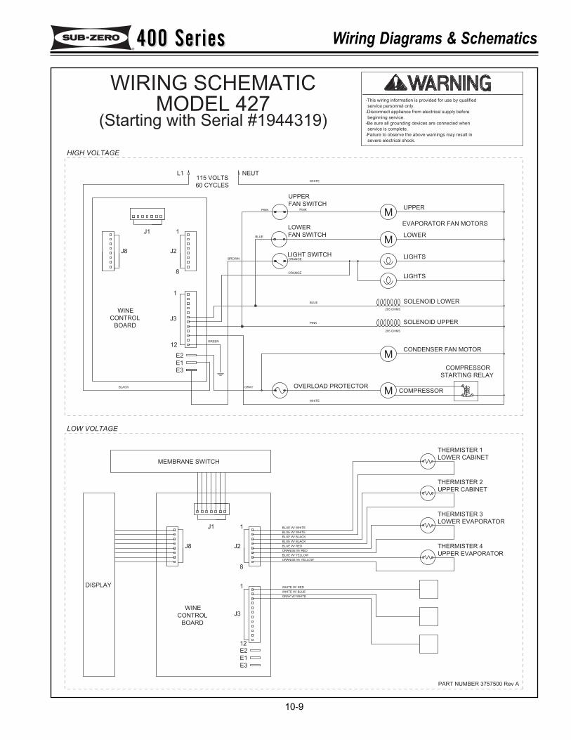
400 Series400 Series Wiring Diagrams & Schematics
10-9
PART NUMBER 3757500 Rev A
MEMBRANE SWITCH
DISPLAY
J8 J2
CONTROL J3
BOARD
12
WINE
1
8
ORANGE W/ YELLOW
BLUE W/ YELLOW
WHITE W/ RED
WHITE W/ BLUE
GRAY W/ WHITE
ORANGE W/ RED
J1 1 BLUE W/ WHITE
BLUE W/ WHITE
BLUE W/ BLACK
BLUE W/ BLACK
BLUE W/ RED THERMISTER 4
UPPER EVAPORATOR
THERMISTER 2
UPPER CABINET
THERMISTER 3
LOWER EVAPORATOR
THERMISTER 1
LOWER CABINET
60 CYCLES
115 VOLTS
GREEN
J3CONTROL
BOARD
BLACK
E3
12
E1
E2
WINE
J8
1
8
J1
J2
1
L1
OVERLOAD PROTECTORGRAY
WHITE
PINK
LIGHT SWITCH
PINK
BROWN
BLUE
ORANGE
ORANGE
STARTING RELAY
SOLENOID UPPER
CONDENSER FAN MOTOR
COMPRESSOR
295 OHMS
COMPRESSOR
EVAPORATOR FAN MOTORS
SOLENOID LOWER
LIGHTS
295 OHMS
LOWER
LIGHTS
FAN SWITCH
UPPER
NEUTWHITE
UPPER
E2
E1
E3
BLUE
LOWER
FAN SWITCH
PINK
M
M
M
M
severe electrical shock.
-Failure to observe the above warnings may result in
service is complete.
-Be sure all grounding devices are connected when
beginning service.
-Disconnect appliance from electrical supply before
service personnel only.
-This wiring information is provided for use by qualified
LOW VOLTAGE
HIGH VOLTAGE
WIRING SCHEMATICMODEL 427
(Starting with Serial #1944319)
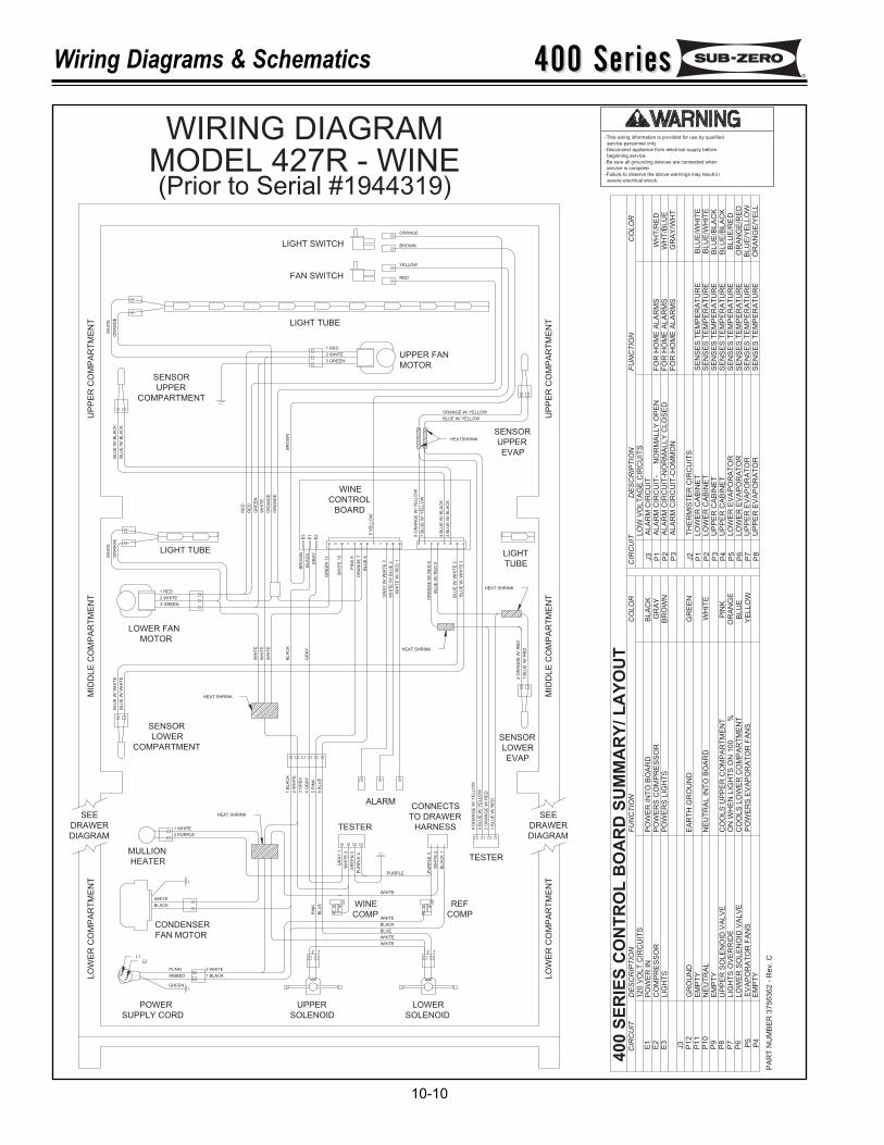
400 Series400 SeriesWiring Diagrams & Schematics
10-10
PA
RT
NU
MB
ER
37
56
36
2 -
Re
v.
C
severe electrical shock.
-Failure to observe the above warnings may result in
service is complete.
-Be sure all grounding devices are connected when
beginning service.
-Disconnect appliance from electrical supply before
service personnel only.
-This wiring information is provided for use by qualified
RIBBED
PLAIN
1 BLACK
2 WHITE
BLACK
WHITE
2 WHITE
3 GREEN
1 RED
LIGHT TUBE
LIGHT SWITCH
FAN SWITCH
LIGHT TUBE
1 RED
2 WHITE
3 GREENUPPER FAN
MOTOR
SENSOR
UPPER
EVAP
COMPARTMENT
SENSOR
UPPER
LIGHT
TUBE
WINE
CONTROL
BOARD
LOWER FAN
MOTOR
SENSOR
LOWER
COMPARTMENTSENSOR
LOWER
EVAP
TESTER
CONDENSER
FAN MOTOR
POWER
SUPPLY CORD
UPPER
SOLENOID
LOWER
SOLENOID
ALARM
ORANGE
BROWN
YELLOW
RED
WH
ITE
OR
AN
GE
ORANGE W/ YELLOW
BLUE W/ YELLOW8
OR
AN
GE
W/
YE
LL
OW
7 B
LU
E W
/ Y
EL
LO
W
4 B
LU
E W
/ B
LA
CK
3 B
LU
E W
/ B
LA
CK
OR
AN
GE
W/
RE
D 6
BL
UE
W/
RE
D 5
BL
UE
W/
WH
ITE
2
BL
UE
W/
WH
ITE
1
WH
ITE
W/
RE
D 1
WH
ITE
W/
BL
UE
2
GR
AY
W/
WH
ITE
3
BL
UE
6
OR
AN
GE
7
PIN
K 8
WH
ITE
10
GR
EE
N 1
2
5 Y
EL
LO
W
BL
UE
W/
BL
AC
K
BL
UE
W/
BL
AC
K
OR
AN
GE
WH
ITE
RE
D
RE
D
GR
EE
N
WH
ITE
OR
AN
GE
OR
AN
GE
WH
ITE
WH
ITE
WH
ITE
BL
AC
K
GR
AY
BL
UE
W/
WH
ITE
BL
UE
W/
WH
ITE
3 B
LU
E W
/ Y
EL
LO
W
4 O
RA
NG
E W
/ Y
EL
LO
W
2 O
RA
NG
E W
/ R
ED
1 B
LU
E W
/ R
ED
2 O
RA
NG
E W
/ R
ED
1 B
LU
E W
/ R
ED
1 B
LA
CK
2 W
HIT
E
4 G
RA
Y
5 P
INK
6 B
LU
E
3 O
PE
N
UP
PE
R C
OM
PA
RT
ME
NT
UP
PE
R C
OM
PA
RT
ME
NT
MID
DLE
CO
MP
AR
TM
EN
T
MID
DLE
CO
MP
AR
TM
EN
T
LO
WE
R C
OM
PA
RT
ME
NT
LO
WE
R C
OM
PA
RT
ME
NT
SEE
DRAWER
DIAGRAM
DRAWER
DIAGRAM
SEE
TESTER
CONNECTS
TO DRAWER
HARNESS
MULLION
HEATER
WINE
COMP
REF
COMP
PU
RP
LE
3
WH
ITE
2
BL
AC
K 1
PU
RP
LE
4
GR
EE
N 3
GR
AY
1
PURPLE
WHITE
WHITE
BLACK
BLUE
WHITE
WHITE
1212
1 WHITE
2 PURPLE
BL
UE
PIN
K
BR
OW
N
WH
ITE
2
E2
E1
E3
GR
AY
BL
AC
K
BR
OW
N
40
0 S
ER
IES
CO
NT
RO
L B
OA
RD
SU
MM
AR
Y/
LA
YO
UT
GREEN
L2L1
HEAT SHRINK
HEAT SHRINK
EM
PT
Y
UP
PE
R S
OL
EN
OID
VA
LV
E
LO
WE
R S
OL
EN
OID
VA
LV
EL
IGH
TS
OV
ER
RID
E
EV
AP
OR
AT
OR
FA
NS
EM
PT
YN
EU
TR
AL
GR
OU
ND
EM
PT
Y
PO
WE
R IN
DE
SC
RIP
TIO
N
CO
MP
RE
SS
OR
12
0 V
OL
T C
IRC
UIT
S
LIG
HT
SE
3E
2E
1
CIR
CU
IT
P5
P4
P7
P8
P6
P9
P1
1P
10
J3
P1
2E
AR
TH
GR
OU
ND
NE
UT
RA
L I
NT
O B
OA
RD
ON
WH
EN
LIG
HT
S O
N 1
00
%C
OO
LS
LO
WE
R C
OM
PA
RT
ME
NT
CO
OL
S U
PP
ER
CO
MP
AR
TM
EN
T
PO
WE
RS
EV
AP
OR
AT
OR
FA
NS
FU
NC
TIO
N
PO
WE
R IN
TO
BO
AR
DP
OW
ER
S C
OM
PR
ES
SO
RP
OW
ER
S L
IGH
TS
AL
AR
M C
IRC
UIT
-N
OR
MA
LL
Y O
PE
NA
LA
RM
CIR
CU
IT-N
OR
MA
LL
Y C
LO
SE
D
HEAT SHRINK
HEAT SHRINK
HEATSHRINK
CIR
CU
IT
BR
OW
NP
2
CO
LO
R
GR
AY
BL
AC
KJ3
P1
YE
LL
OW
PIN
KO
RA
NG
EB
LU
E
WH
ITE
GR
EE
NJ2
P3
P3
P2
P1
P7
P6
P5
P4
P8
DE
SC
RIP
TIO
N
LO
W V
OL
TA
GE
CIR
CU
ITS
AL
AR
M C
IRC
UIT
UP
PE
R E
VA
PO
RA
TO
RU
PP
ER
EV
AP
OR
AT
OR
LO
WE
R E
VA
PO
RA
TO
RL
OW
ER
EV
AP
OR
AT
OR
TH
ER
MIS
TE
R C
IRC
UIT
S
AL
AR
M C
IRC
UIT
-CO
MM
ON
LO
WE
R C
AB
INE
TL
OW
ER
CA
BIN
ET
UP
PE
R C
AB
INE
TU
PP
ER
CA
BIN
ET
BL
UE
/YE
LL
OW
OR
AN
GE
/YE
LL
OR
AN
GE
/RE
D
BL
UE
/BL
AC
KB
LU
E/B
LA
CK
FO
R H
OM
E A
LA
RM
SF
OR
HO
ME
AL
AR
MS
FU
NC
TIO
N
SE
NS
ES
TE
MP
ER
AT
UR
ES
EN
SE
S T
EM
PE
RA
TU
RE
SE
NS
ES
TE
MP
ER
AT
UR
ES
EN
SE
S T
EM
PE
RA
TU
RE
SE
NS
ES
TE
MP
ER
AT
UR
ES
EN
SE
S T
EM
PE
RA
TU
RE
SE
NS
ES
TE
MP
ER
AT
UR
ES
EN
SE
S T
EM
PE
RA
TU
RE
FO
R H
OM
E A
LA
RM
SW
HT
/BL
UE
WH
T/R
ED
CO
LO
R
BL
UE
/WH
ITE
BL
UE
/WH
ITE
GR
AY
/WH
T
BL
UE
/RE
D
WIRING DIAGRAMMODEL 427R - WINE(Prior to Serial #1944319)
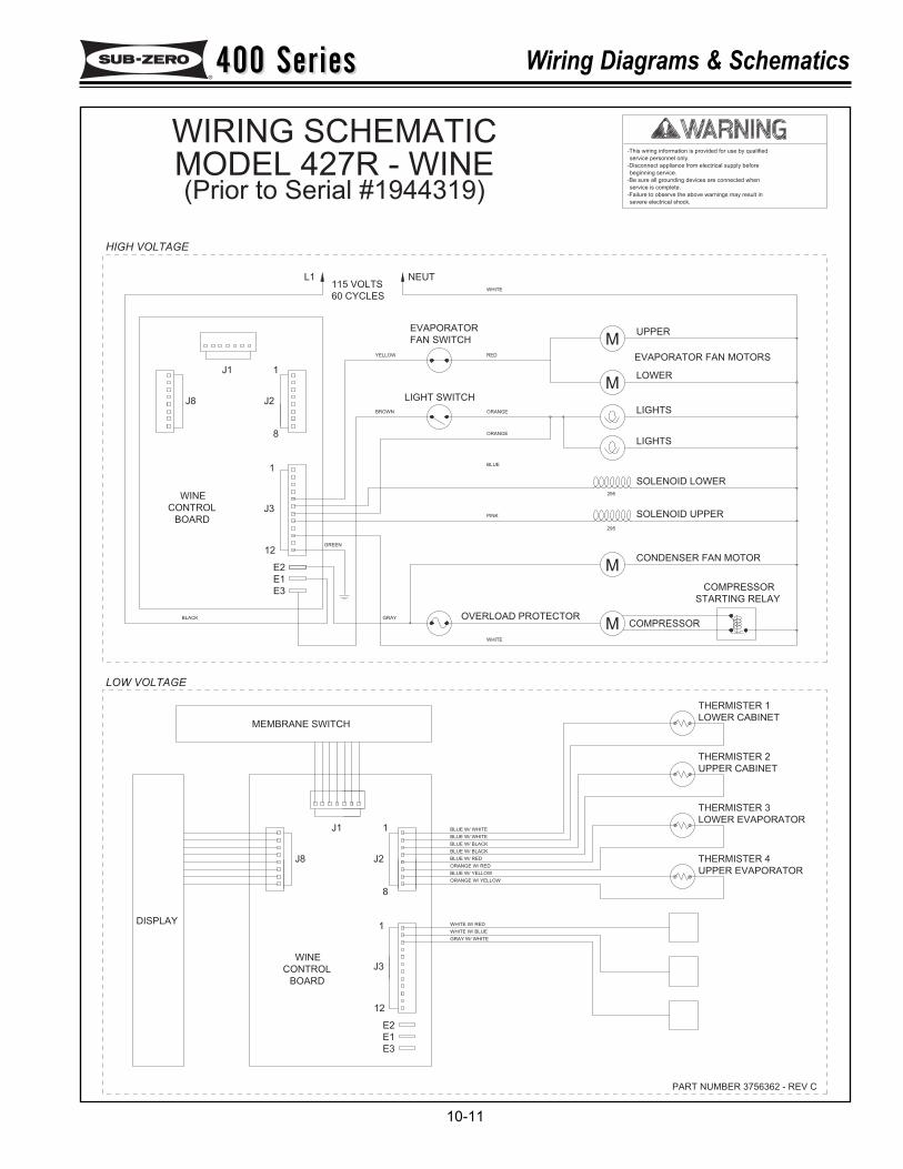
400 Series400 Series Wiring Diagrams & Schematics
10-11
severe electrical shock.
-Failure to observe the above warnings may result in
service is complete.
-Be sure all grounding devices are connected when
beginning service.
-Disconnect appliance from electrical supply before
service personnel only.
-This wiring information is provided for use by qualified
PART NUMBER 3756362 - REV C
LOW VOLTAGE
HIGH VOLTAGE
DISPLAY
CONTROL
BOARD
WINEJ3
WHITE W/ BLUE
GRAY W/ WHITE
WHITE W/ RED
ORANGE W/ YELLOW
MEMBRANE SWITCH
J8
1
J2
8
J1
BLUE W/ YELLOW
ORANGE W/ RED
BLUE W/ BLACK
BLUE W/ BLACK
BLUE W/ RED
BLUE W/ WHITE
BLUE W/ WHITE
THERMISTER 2
UPPER CABINET
THERMISTER 3
LOWER EVAPORATOR
THERMISTER 4
UPPER EVAPORATOR
THERMISTER 1
LOWER CABINET
60 CYCLES
115 VOLTS
GREEN
J3CONTROL
BOARD
BLACK
E3
12
E1
E2
WINE
J8
1
8
J1
J2
1
L1
OVERLOAD PROTECTORGRAY
WHITE
PINK
LIGHT SWITCH
YELLOW
BROWN
BLUE
ORANGE
ORANGE
RED
STARTING RELAY
SOLENOID UPPER
CONDENSER FAN MOTOR
COMPRESSORM
M
295
COMPRESSOR
EVAPORATOR FAN MOTORS
SOLENOID LOWER
LIGHTS
295
LOWER
LIGHTS
M
FAN SWITCH
EVAPORATOR
NEUTWHITE
UPPERM
1
12
E3
E2
E1
WIRING SCHEMATICMODEL 427R - WINE(Prior to Serial #1944319)
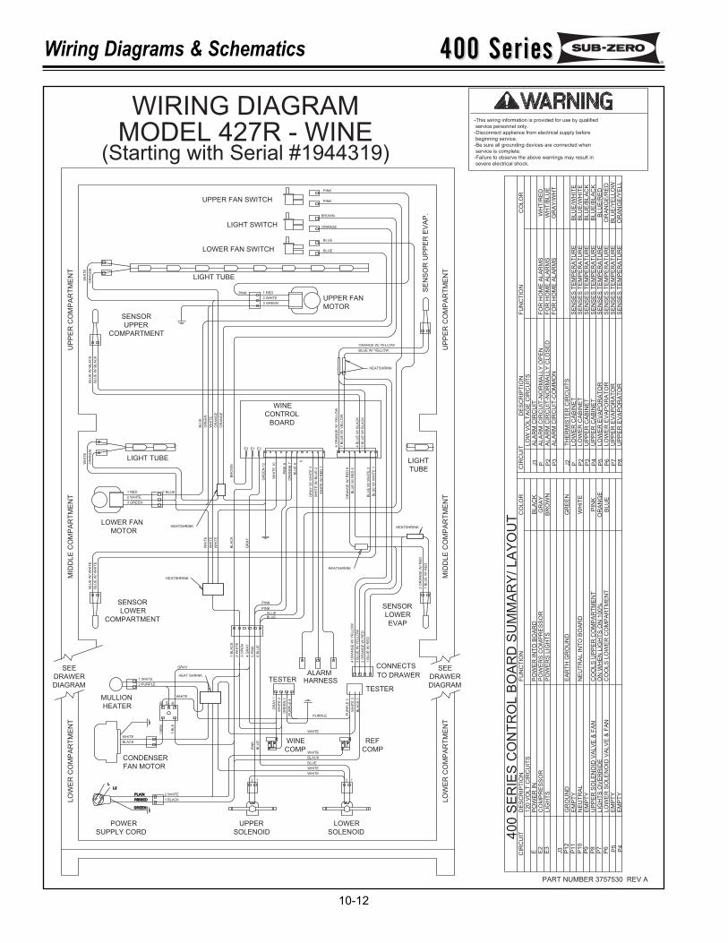
400 Series400 SeriesWiring Diagrams & Schematics
10-12
MULLION
HEATER
WINE
COMP
REF
COMP
PU
RP
LE
3
WH
ITE
2
BL
AC
K 1
PU
RP
LE
4
GR
EE
N 3
GR
AY
1
PURPLE
WHITE
WHITE
BLACK
BLUE
WHITE
WHITE
1212
1 WHITE
2 PURPLE
BL
UE
PIN
K
WH
ITE
2
WHITE
LL2
RIBBED
GREEN
PLAIN
1 BLACK
2 WHITE
BLACK
WHITE
CONDENSER
FAN MOTOR
POWER
SUPPLY CORD
UPPER
SOLENOID
LOWER
SOLENOID
ALARMHEAT SHRINK
LO
WE
R C
OM
PA
RT
ME
NT
LO
WE
R C
OM
PA
RT
ME
NT
SEE
DRAWER
DIAGRAM
DRAWER
DIAGRAM
SEE
MID
DL
E C
OM
PA
RT
ME
NT
MID
DL
E C
OM
PA
RT
ME
NT
GR
AY
BL
AC
K
WH
ITE
WH
ITE
WH
ITE
COMPARTMENT
BL
UE
W/
WH
ITE
BL
UE
W/
WH
ITE
3 O
PE
N
2 W
HIT
E
1 B
LA
CK
6 B
LU
E
5 P
INK
4 G
RA
Y
HEATSHRINK
LOWER
SENSOR
EVAP
LOWER
SENSOR
1 B
LU
E W
/ R
ED
2 O
RA
NG
E W
/ R
ED
4 O
RA
NG
E W
/ Y
EL
LO
W
3 B
LU
E W
/ Y
EL
LO
W
HEATSHRINK
BLUE
PINK
BLUE
PINK
1 B
LU
E W
/ R
ED
2 O
RA
NG
E W
/ R
ED
UPPER FAN SWITCH
LOWER FAN SWITCH
LIGHT SWITCH
BL
UE
W/
BL
AC
K
BL
UE
W/
BL
AC
K
MOTOR
LOWER FAN
WH
ITE
OR
AN
GE
LIGHT TUBE
3 GREEN
1 RED
2 WHITE
1 BLUE
BR
OW
N
GR
EE
N
BL
UE
OR
AN
GE
OR
AN
GE
WH
ITE
COMPARTMENT
UP
PE
R C
OM
PA
RT
ME
NT
OR
AN
GE
WH
ITE
SENSOR
UPPER
LIGHT TUBE
PINK
HEATSHRINK
BL
UE
6
GR
EE
N 1
2
WH
ITE
10
OR
AN
GE
7
PIN
K 8
GR
AY
W/ W
HIT
E 3
WH
ITE
W/ B
LU
E 2
WH
ITE
W/ R
ED
1
5
BLU
E W
/ W
HIT
E 2
BL
UE
W/ R
ED
5
OR
AN
GE
W/ R
ED
6
BLU
E W
/ W
HIT
E 1
CONTROL
BOARD
WINE
3 B
LU
E W
/ B
LA
CK
4 B
LU
E W
/ B
LA
CK
7 B
LU
E W
/ Y
EL
LO
W
8 O
RA
NG
E W
/ Y
EL
LO
W
HEATSHRINK
TUBE
LIGHT
MOTOR
UPPER FAN3 GREEN
2 WHITE
1 RED
BLUE W/ YELLOW
ORANGE W/ YELLOW
PINK
PINK
BLUE
BLUE
BROWN
ORANGE
SE
NS
OR
UP
PE
R E
VA
P.
UP
PE
R C
OM
PA
RT
ME
NT
TESTER
456
GRAY
3 B
LK
1 B
RN
CIR
CU
IT
P P2
P3
J3
J2
P P2
P3
P4
P5
P6
P8
P7
40
0 S
ER
IES
CO
NT
RO
L B
OA
RD
SU
MM
AR
Y/ L
AY
OU
TC
IRC
UIT
E E2
E3
P1
2J3
P1
0P
11
P9
P6
P8
P7 P4
P5
LIG
HT
SP
OW
ER
S L
IGH
TS
BR
OW
NP
OW
ER
S C
OM
PR
ES
SO
RP
OW
ER
IN
TO
BO
AR
D120 V
OLT
CIR
CU
ITS
CO
MP
RE
SS
OR
DE
SC
RIP
TIO
N
PO
WE
R IN
FU
NC
TIO
N
BL
AC
KG
RA
Y
CO
LO
R
CO
OLS
UP
PE
R C
OM
PA
RT
ME
NT
CO
OLS
LO
WE
R C
OM
PA
RT
ME
NT
ON
WH
EN
LIG
HT
S O
N 1
00%
NE
UT
RA
L IN
TO
BO
AR
D
EA
RT
H G
RO
UN
D
EM
PT
Y
GR
OU
ND
NE
UT
RA
LE
MP
TY
LIG
HT
S O
VE
RR
IDE
LO
WE
R S
OLE
NO
ID V
ALV
E &
FA
N
UP
PE
R S
OLE
NO
ID V
ALV
E &
FA
N
EM
PT
Y
GR
EE
N
WH
ITE
BL
UE
OR
AN
GE
PIN
K
ALA
RM
CIR
CU
IT-N
OR
MA
LLY
CLO
SE
DF
OR
HO
ME
ALA
RM
SW
HT
/BLU
EF
OR
HO
ME
ALA
RM
S
LO
W V
OLT
AG
E C
IRC
UIT
SA
LA
RM
CIR
CU
IT
DE
SC
RIP
TIO
NF
UN
CT
ION
CO
LO
R
WH
T/R
ED
FO
R H
OM
E A
LA
RM
S
SE
NS
ES
TE
MP
ER
AT
UR
E
ALA
RM
CIR
CU
IT-C
OM
MO
N
UP
PE
R C
AB
INE
T
LO
WE
R C
AB
INE
TLO
WE
R C
AB
INE
T
TH
ER
MIS
TE
R C
IRC
UIT
S
UP
PE
R C
AB
INE
TLO
WE
R E
VA
PO
RA
TO
RLO
WE
R E
VA
PO
RA
TO
R
UP
PE
R E
VA
PO
RA
TO
RU
PP
ER
EV
AP
OR
AT
OR
GR
AY
/WH
T
BLU
E/W
HIT
EB
LU
E/W
HIT
EB
LU
E/B
LA
CK
BL
UE
/BL
AC
KB
LU
E/R
ED
OR
AN
GE
/RE
D
OR
AN
GE
/YE
LL
BLU
E/Y
ELLO
W
ALA
RM
CIR
CU
IT-N
OR
MA
LLY
OP
EN
SE
NS
ES
TE
MP
ER
AT
UR
ES
EN
SE
S T
EM
PE
RA
TU
RE
SE
NS
ES
TE
MP
ER
AT
UR
ES
EN
SE
S T
EM
PE
RA
TU
RE
SE
NS
ES
TE
MP
ER
AT
UR
ES
EN
SE
S T
EM
PE
RA
TU
RE
SE
NS
ES
TE
MP
ER
AT
UR
EE
MP
TY
TESTER
CONNECTS
TO DRAWERHARNESS
E2
HEATSHRINK
E3 E1
-This wiring information is provided for use by qualified
service personnel only.
-Disconnect appliance from electrical supply before
beginning service.
-Be sure all grounding devices are connected when
service is complete.
-Failure to observe the above warnings may result in
severe electrical shock.
WIRING DIAGRAMMODEL 427R - WINE
(Starting with Serial #1944319)
PART NUMBER 3757530 REV A
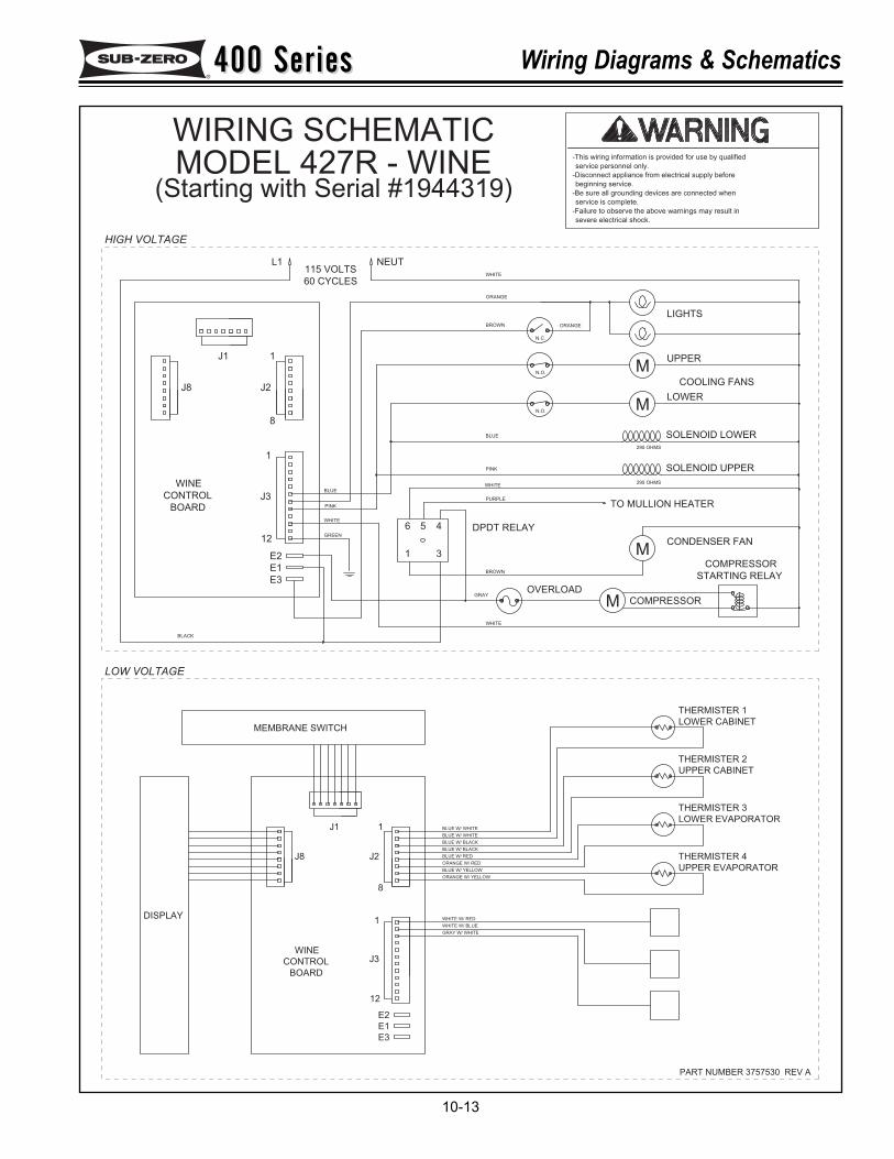
400 Series400 Series Wiring Diagrams & Schematics
10-13
DISPLAY
CONTROL
BOARD
WINEJ3
WHITE W/ BLUE
GRAY W/ WHITE
WHITE W/ RED
ORANGE W/ YELLOW
MEMBRANE SWITCH
J8
1
J2
8
J1
BLUE W/ YELLOW
ORANGE W/ RED
BLUE W/ BLACK
BLUE W/ BLACK
BLUE W/ RED
BLUE W/ WHITE
BLUE W/ WHITE
THERMISTER 2
UPPER CABINET
THERMISTER 3
LOWER EVAPORATOR
THERMISTER 4
UPPER EVAPORATOR
THERMISTER 1
LOWER CABINET
1
12
E3
E2
E1
J1
BOARD
BLACK
WINE
CONTROL
J8
TO MULLION HEATER
SOLENOID LOWER
COOLING FANS
CONDENSER FAN
SOLENOID UPPER
STARTING RELAY
PINK
E2
E3
E1
12
WHITE
GREEN
1
J3
J2
8
BLUE
1
56
3
4 DPDT RELAY
WHITE
GRAY
BROWN
OVERLOAD
BLUE
PURPLE
WHITE
PINK
N.O.
N.O.
COMPRESSOR
295 OHMS
295 OHMS
LOWER
115 VOLTS
60 CYCLES
1
L1 NEUT
ORANGE
BROWN
WHITE
N.C.
ORANGE
UPPER
LIGHTS
COMPRESSOR
M
M
M
M
PART NUMBER 3757530 REV A
severe electrical shock.
-Failure to observe the above warnings may result in
service is complete.
-Be sure all grounding devices are connected when
beginning service.
-Disconnect appliance from electrical supply before
service personnel only.
-This wiring information is provided for use by qualified
LOW VOLTAGE
HIGH VOLTAGE
WIRING SCHEMATICMODEL 427R - WINE
(Starting with Serial #1944319)
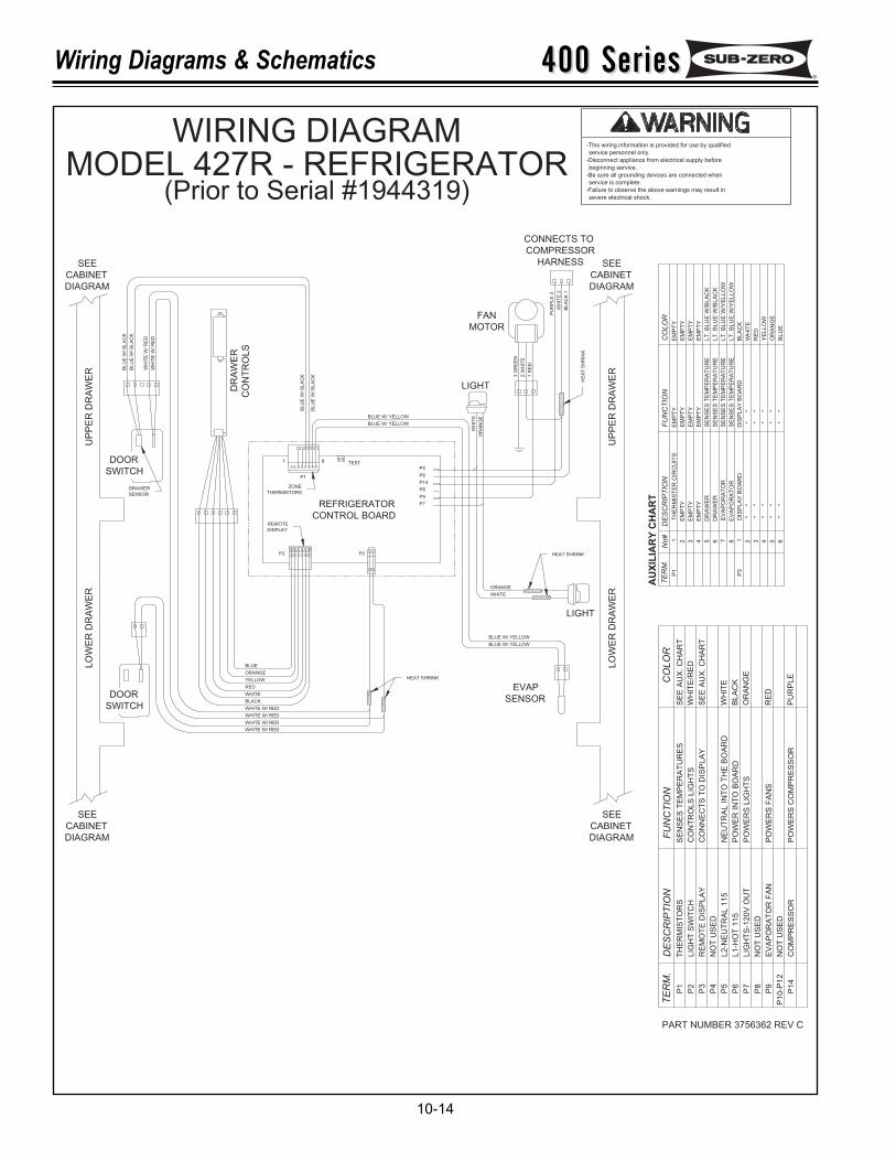
400 Series400 SeriesWiring Diagrams & Schematics
10-14
severe electrical shock.
-Failure to observe the above warnings may result in
service is complete.
-Be sure all grounding devices are connected when
beginning service.
-Disconnect appliance from electrical supply before
service personnel only.
-This wiring information is provided for use by qualified
UP
PE
R D
RA
WE
R
UP
PE
R D
RA
WE
RLO
WE
R D
RA
WE
R
LO
WE
R D
RA
WE
R
3 G
RE
EN
2 W
HIT
E
1 R
ED
P1
1
DOOR
SWITCH
DOOR
SWITCH
FAN
MOTOR
LIGHT
CONNECTS TO
COMPRESSOR
HARNESS
EVAP
SENSOR
LIGHT
REFRIGERATOR
CONTROL BOARD
TEST
P2P3
P1
1 8
P5
P6
P14
P8
P9
P7
BLUE W/ YELLOW
BLUE W/ YELLOW
BLU
E W
/ B
LA
CK
BLU
E W
/ B
LA
CK
BLUE
ORANGE
YELLOW
RED
WHITE
BLACK
WHITE W/ RED
WHITE W/ RED
WHITE W/ RED
WHITE W/ RED
BLU
E W
/ B
LA
CK
BLU
E W
/ B
LA
CK
WH
ITE
W/ R
ED
WH
ITE
W/ R
ED
PU
RP
LE
3
WH
ITE
2
BLA
CK
1
SEE
CABINET
DIAGRAM
CABINET
DIAGRAM
SEE
SEE
DIAGRAM
CABINETCABINET
DIAGRAM
SEE
DR
AW
ER
CO
NT
RO
LS
BLUE W/ YELLOW
BLUE W/ YELLOW
ORANGE
WHITE
OR
AN
GE
WH
ITE
CO
NN
EC
TS
TO
DIS
PLA
Y
CO
NT
RO
LS
LIG
HT
S
SE
NS
ES
TE
MP
ER
AT
UR
ES
PO
WE
RS
CO
MP
RE
SS
OR
PO
WE
RS
FA
NS
PO
WE
RS
LIG
HT
S
PO
WE
R IN
TO
BO
AR
D
NE
UT
RA
L IN
TO
TH
E B
OA
RD
FU
NC
TIO
N
P2
LIG
HT
SW
ITC
H
P14
CO
MP
RE
SS
OR
L1
-HO
T 1
15
LIG
HT
S-1
20V
OU
T
L2
-NE
UT
RA
L 1
15
RE
MO
TE
DIS
PLA
Y
EV
AP
OR
AT
OR
FA
N
P6
P9
P7
P5
P3
DE
SC
RIP
TIO
N
TH
ER
MIS
TO
RS
P1
TE
RM
.
EM
PT
YE
MP
TY
WH
ITE
/RE
D
PU
RP
LE
OR
AN
GE
SE
E A
UX
. C
HA
RT
BL
AC
K
RE
D
WH
ITE
"
"
"
"
AU
XIL
IAR
Y C
HA
RT
"
"
"
"
"
"
"
"
"
"
"
"
SE
NS
ES
TE
MP
ER
AT
UR
E
SE
NS
ES
TE
MP
ER
AT
UR
E
SE
NS
ES
TE
MP
ER
AT
UR
E
SE
NS
ES
TE
MP
ER
AT
UR
E
EV
AP
OR
AT
OR
"
"
DIS
PLA
Y B
OA
RD
DIS
PL
AY
BO
AR
DP
3
"
"
EV
AP
OR
AT
OR
EM
PT
Y
DR
AW
ER
DR
AW
ER
EM
PT
Y
TE
RM
.C
OL
OR
SE
E A
UX
. C
HA
RT
EM
PT
Y
EM
PT
Y
FU
NC
TIO
N
TH
ER
MIS
TE
R C
IRC
UIT
SP
1
EM
PT
Y
DE
SC
RIP
TIO
N
RE
D
CO
LO
R
EM
PT
Y
EM
PT
Y
EM
PT
Y
LT
. B
LU
E W
/BLA
CK
LT
. B
LU
E W
/BLA
CK
LT
. B
LU
E W
/YE
LLO
W
LT
. B
LU
E W
/YE
LLO
W
EM
PT
Y
BLA
CK
WH
ITE
YE
LLO
W
OR
AN
GE
BLU
E
3
No
#
31 2 75 64 1 28 5 64
P4
NO
T U
SE
D
P8
NO
T U
SE
D
P10-P
12
NO
T U
SE
D
HEAT SHRINK
DRAWER
SENSOR
REMOTE
DISPLAY
ZONE
THERMISTORS
PART NUMBER 3756362 REV C
HEAT SHRINK
HE
AT
SH
RIN
K
WIRING DIAGRAMMODEL 427R - REFRIGERATOR
(Prior to Serial #1944319)
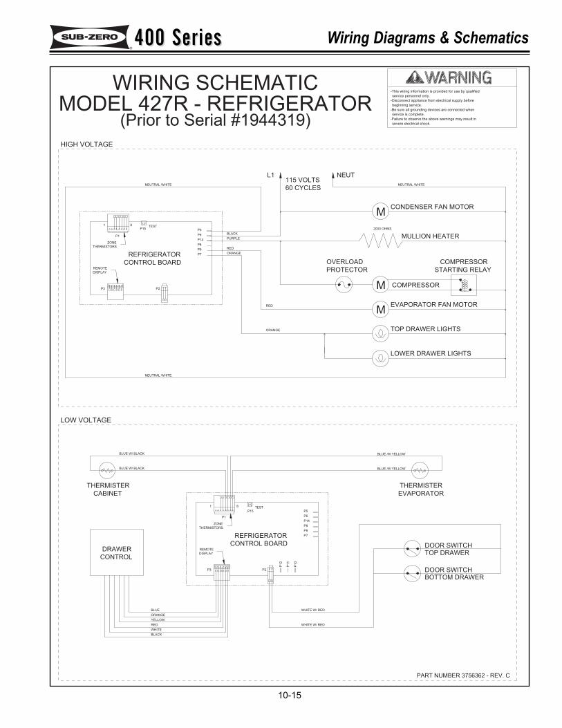
400 Series400 Series Wiring Diagrams & Schematics
10-15
severe electrical shock.
-Failure to observe the above warnings may result in
service is complete.
-Be sure all grounding devices are connected when
beginning service.
-Disconnect appliance from electrical supply before
service personnel only.
-This wiring information is provided for use by qualified
LOW VOLTAGE
HIGH VOLTAGE
PART NUMBER 3756362 - REV. C
BOTTOM DRAWER
WHITE W/ RED
WHITE W/ REDBLUE
RED
WHITE
BLACK
ORANGE
YELLOW
115 VOLTS
60 CYCLES
NEUTRAL WHITE
THERMISTER
CONTROL
DRAWER
BLUE W/ BLACK
CABINET
BLUE W/ BLACK
CONTROL BOARD
REFRIGERATOR
P1
P3
1 8
P6
P2
P1
2
P8
P14
P1
0
P1
1
P9
P7
TESTP15 P5
NEUTRAL WHITE
REFRIGERATOR
CONTROL BOARD
P3 P2
1
P1
TESTP15
8
P5
P9
P7
P8
P14
P6
RED
PURPLE
ORANGE
BLACK
RED
ORANGE
L1
BLUE /W YELLOW
DOOR SWITCH
TOP DRAWERDOOR SWITCH
THERMISTER
EVAPORATOR
BLUE /W YELLOW
LOWER DRAWER LIGHTS
CONDENSER FAN MOTOR
STARTING RELAY
COMPRESSOR
EVAPORATOR FAN MOTOR
TOP DRAWER LIGHTS
COMPRESSORM
M
PROTECTOR
OVERLOAD
2000 OHMS
MULLION HEATER
NEUTRAL WHITE
NEUT
M
REMOTE
DISPLAY
ZONE
THERMISTORS
REMOTE
DISPLAY
ZONE
THERMISTORS
WIRING SCHEMATICMODEL 427R - REFRIGERATOR
(Prior to Serial #1944319)
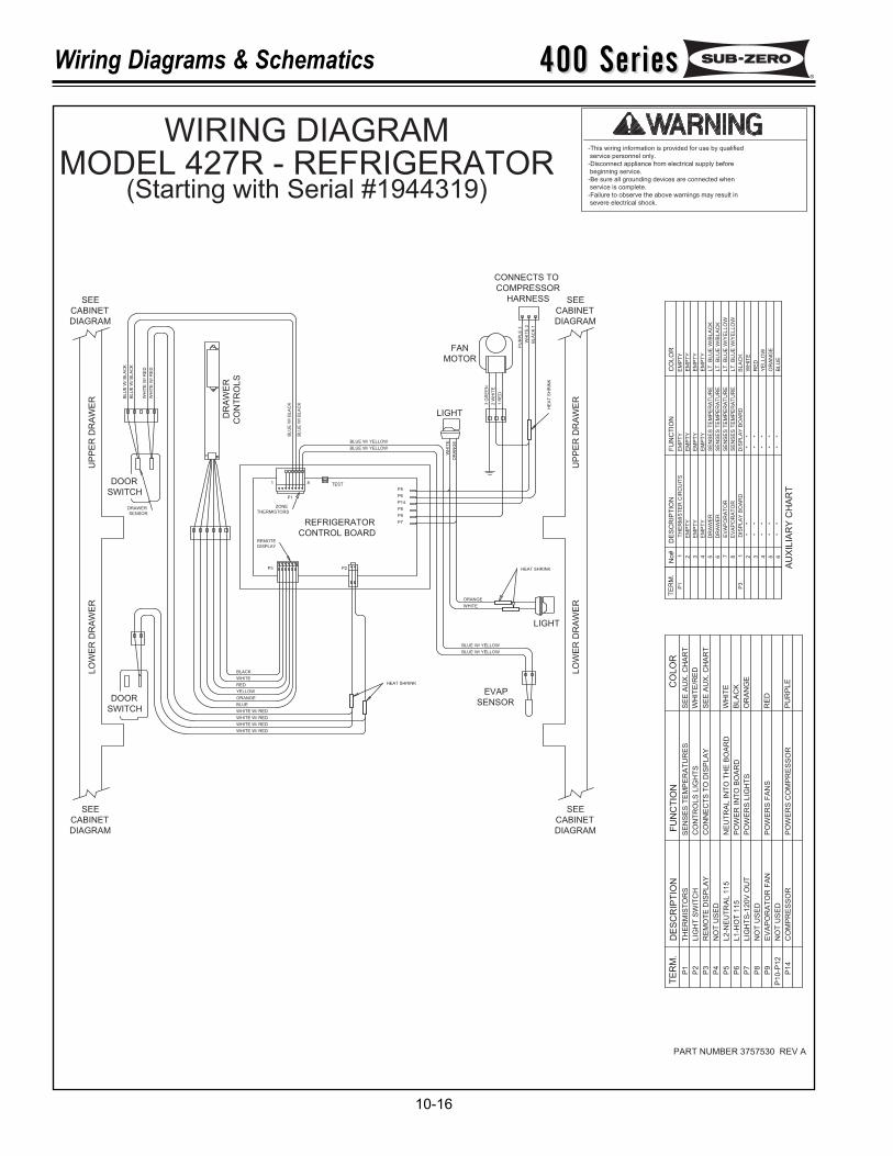
400 Series400 SeriesWiring Diagrams & Schematics
10-16
DOOR
SWITCH
DOOR
SWITCH
UP
PE
R D
RA
WE
R
UP
PE
R D
RA
WE
RLO
WE
R D
RA
WE
R
LO
WE
R D
RA
WE
R
3 G
RE
EN
2 W
HIT
E
1 R
ED
P1
1
SEE
CABINET
DIAGRAM
CABINET
DIAGRAM
SEE
SEE
DIAGRAM
CABINETCABINET
DIAGRAM
SEE
CO
NN
EC
TS
TO
DIS
PL
AY
CO
NT
RO
LS
LIG
HT
S
SE
NS
ES
TE
MP
ER
AT
UR
ES
PO
WE
RS
CO
MP
RE
SS
OR
PO
WE
RS
FA
NS
PO
WE
RS
LIG
HT
S
PO
WE
R IN
TO
BO
AR
D
NE
UT
RA
L IN
TO
TH
E B
OA
RD
FU
NC
TIO
N
P2
LIG
HT
SW
ITC
H
P1
4C
OM
PR
ES
SO
R
L1
-HO
T 1
15
LIG
HT
S-1
20
V O
UT
L2
-NE
UT
RA
L 1
15
RE
MO
TE
DIS
PL
AY
EV
AP
OR
AT
OR
FA
N
P6
P9
P7
P5
P3
DE
SC
RIP
TIO
N
TH
ER
MIS
TO
RS
P1
TE
RM
.
EM
PT
YE
MP
TY
WH
ITE
/RE
D
PU
RP
LE
OR
AN
GE
SE
E A
UX
. C
HA
RT
BL
AC
K
RE
D
WH
ITE
"
"
"
"
AU
XIL
IAR
Y C
HA
RT
"
"
"
"
"
"
"
"
"
"
"
"
SE
NS
ES
TE
MP
ER
AT
UR
E
SE
NS
ES
TE
MP
ER
AT
UR
E
SE
NS
ES
TE
MP
ER
AT
UR
E
SE
NS
ES
TE
MP
ER
AT
UR
E
EV
AP
OR
AT
OR
"
"
DIS
PL
AY
BO
AR
DD
ISP
LA
Y B
OA
RD
P3
"
"
EV
AP
OR
AT
OR
EM
PT
Y
DR
AW
ER
DR
AW
ER
EM
PT
Y
TE
RM
.C
OL
OR
SE
E A
UX
. C
HA
RT
EM
PT
Y
EM
PT
Y
FU
NC
TIO
N
TH
ER
MIS
TE
R C
IRC
UIT
SP
1
EM
PT
Y
DE
SC
RIP
TIO
N
RE
D
CO
LO
R
EM
PT
Y
EM
PT
Y
EM
PT
Y
LT
. B
LU
E W
/BLA
CK
LT
. B
LU
E W
/BLA
CK
LT
. B
LU
E W
/YE
LLO
W
LT
. B
LU
E W
/YE
LLO
W
EM
PT
Y
BL
AC
K
WH
ITE
YE
LLO
W
OR
AN
GE
BLU
E
3
No
#
31 2 75 64 1 28 5 64
P4
NO
T U
SE
D
P8
NO
T U
SE
D
P1
0-P
12
NO
T U
SE
D
FAN
MOTOR
LIGHT
CONNECTS TO
COMPRESSOR
HARNESS
EVAP
SENSOR
LIGHT
REFRIGERATOR
CONTROL BOARDREMOTE
DISPLAY
ZONE
THERMISTORS
TEST
P2P3
P1
1 8
P5
P6
P14
P8
P9
P7
BLUE W/ YELLOW
BLUE W/ YELLOW
BLU
E W
/ B
LA
CK
BLU
E W
/ B
LA
CK
BLACK
WHITE
RED
YELLOW
ORANGE
BLUE
WHITE W/ RED
WHITE W/ RED
WHITE W/ RED
WHITE W/ RED
BLU
E W
/ B
LA
CK
BLU
E W
/ B
LA
CK
WH
ITE
W/ R
ED
WH
ITE
W/ R
ED
PU
RP
LE
3
WH
ITE
2
BLA
CK
1
DRAWER
SENSOR
DR
AW
ER
CO
NT
RO
LS
BLUE W/ YELLOW
BLUE W/ YELLOW
ORANGE
WHITE
OR
AN
GE
WH
ITE
HEAT SHRINK
HEAT SHRINK
HE
AT
SH
RIN
K
PART NUMBER 3757530 REV A
-This wiring information is provided for use by qualified
service personnel only.
-Disconnect appliance from electrical supply before
beginning service.
-Be sure all grounding devices are connected when
service is complete.
-Failure to observe the above warnings may result in
severe electrical shock.
WIRING DIAGRAMMODEL 427R - REFRIGERATOR
(Starting with Serial #1944319)
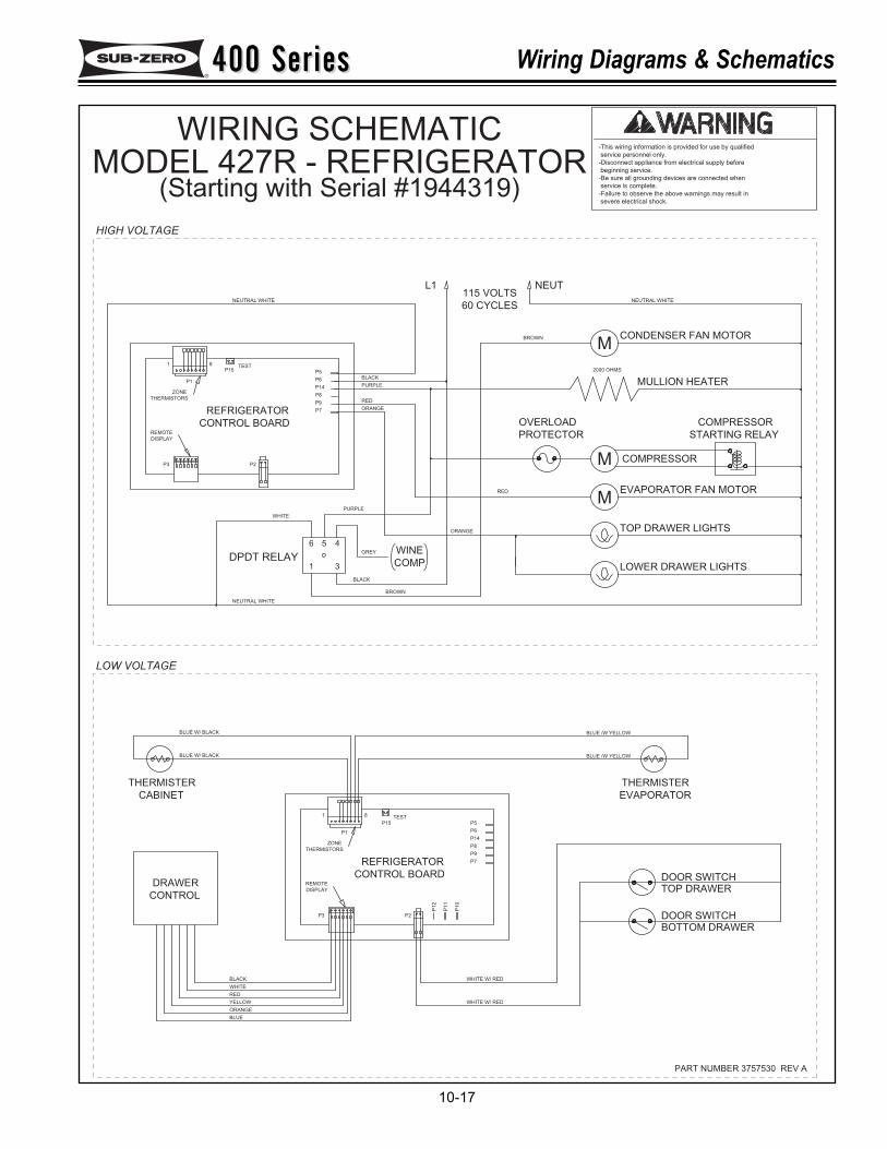
400 Series400 Series Wiring Diagrams & Schematics
10-17
-This wiring information is provided for use by qualified
service personnel only.
-Disconnect appliance from electrical supply before
beginning service.
-Be sure all grounding devices are connected when
service is complete.
-Failure to observe the above warnings may result in
severe electrical shock.
WIRING SCHEMATICMODEL 427R - REFRIGERATOR
(Starting with Serial #1944319)
PART NUMBER 3757530 REV A
115 VOLTS
60 CYCLES
L1
STARTING RELAY
COMPRESSOR
COMPRESSOR
PROTECTOR
OVERLOAD
NEUT
31
56 4
DPDT RELAY
BOTTOM DRAWER
WHITE W/ RED
WHITE W/ RED
BLUE
RED
WHITE
BLACK
ORANGE
YELLOW
NEUTRAL WHITE
THERMISTER
CONTROL
DRAWER
BLUE W/ BLACK
CABINET
BLUE W/ BLACK
CONTROL BOARD
REFRIGERATOR
ZONE
THERMISTORS
P1
REMOTE
DISPLAY
P3
1 8
P6
P2
P12
P8
P14
P1
0
P11
P9
P7
TESTP15 P5
NEUTRAL WHITE
REFRIGERATOR
CONTROL BOARDREMOTE
DISPLAY
P3 P2
ZONE
THERMISTORS
1
P1
TESTP15
8
P5
P9
P7
P8
P14
P6
RED
PURPLE
ORANGE
BLACK
RED
ORANGE
BLUE /W YELLOW
DOOR SWITCH
TOP DRAWERDOOR SWITCH
THERMISTER
EVAPORATOR
BLUE /W YELLOW
LOWER DRAWER LIGHTS
CONDENSER FAN MOTOR
EVAPORATOR FAN MOTOR
TOP DRAWER LIGHTS
M
M
2000 OHMS
MULLION HEATER
NEUTRAL WHITE
M
LOW VOLTAGE
HIGH VOLTAGE
PURPLE
BLACK
GREY
WHITE
BROWN
WINE
COMP
BROWN
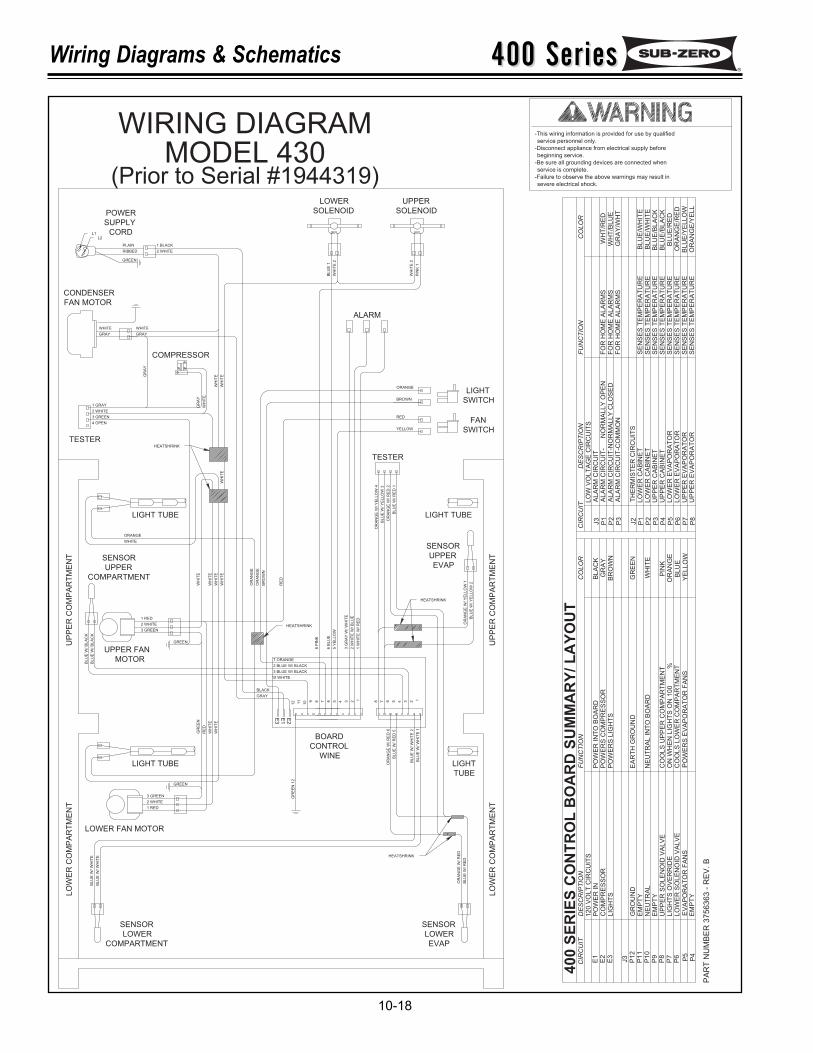
400 Series400 SeriesWiring Diagrams & Schematics
10-18
11
12
10 89 67 5 234 1
BOARD
WINE
CONTROL
368 7 5 4 12
LIGHT
SWITCH
SWITCH
FAN
WHITE
GRAY
1 BLACK
2 WHITE
PLAIN
RIBBED
3 GREEN
1 GRAY
2 WHITE
TESTER
POWER
SUPPLY
CORD
LOWER
SOLENOID SOLENOID
UPPER
BL
UE
1
WH
ITE
2
PIN
K 1
WH
ITE
2
ALARM
BROWN
YELLOW
RED
ORANGE
TESTER
OR
AN
GE
W/
YE
LL
OW
4
BL
UE
W/ Y
EL
LO
W 3
OR
AN
GE
W/
RE
D 2
BL
UE
W/
RE
D 1
LIGHT TUBE
SENSOR
UPPER
EVAP
OR
AN
GE
W/ Y
EL
LO
W 1
BL
UE
W/
YE
LL
OW
2
LIGHT
TUBE
LIGHT TUBE
LIGHT TUBE
LOWER FAN MOTOR
LOWER
EVAP
SENSORSENSOR
LOWER
COMPARTMENT
SENSOR
UPPER
COMPARTMENT
UPPER FAN
MOTOR
BL
UE
W/
WH
ITE
BL
UE
W/
WH
ITE
BL
UE
W/ W
HIT
E 1
BL
UE
W/ W
HIT
E 2
BL
UE
W/ R
ED
5
OR
AN
GE
W/ R
ED
6
2 BLUE W/ BLACK
3 BLUE W/ BLACK
BL
UE
W/
BL
AC
K
BL
UE
W/
BL
AC
K
1 W
HIT
E W
/ R
ED
2 W
HIT
E W
/ B
LU
E
3 G
RA
Y W
/ W
HIT
E
5 Y
EL
LO
W
6 B
LU
E
8 P
INK
10 WHITE
WH
ITE
WH
ITE
RE
D
GR
EE
N
ORANGE
WHITE
WH
ITE
OR
AN
GE
OR
AN
GE
RE
D
7 ORANGE
OR
AN
GE
W/
RE
D
BL
UE
W/
RE
D
WH
ITE
WH
ITE
WH
ITE
WHITE
GRAY
GR
AY
WH
ITE
WH
ITE
WH
ITE
WH
ITE
GR
AY
GR
EE
N 1
2
2 WHITE
1 RED
3 GREEN
2 WHITE
3 GREEN
1 RED
GREEN
GREEN
UP
PE
R C
OM
PA
RT
ME
NT
UP
PE
R C
OM
PA
RT
ME
NT
LO
WE
R C
OM
PA
RT
ME
NT
LO
WE
R C
OM
PA
RT
ME
NT
CONDENSER
FAN MOTOR
COMPRESSOR
4 OPEN
BR
OW
N
GRAY
BLACK
E3
E1
E2
HEATSHRINK
PA
RT
NU
MB
ER
3756363 -
RE
V. B
400 S
ER
IES
CO
NT
RO
L B
OA
RD
SU
MM
AR
Y/ L
AY
OU
T
HEATSHRINK
CIR
CU
IT
J3
E1
E3
E2
P6
P1
1P
10
P1
2
P7
P8
P9 P5
P4
DE
SC
RIP
TIO
N
CO
MP
RE
SS
OR
12
0 V
OL
T C
IRC
UIT
SP
OW
ER
IN
LIG
HT
S
UP
PE
R S
OL
EN
OID
VA
LV
E
LO
WE
R S
OL
EN
OID
VA
LV
EL
IGH
TS
OV
ER
RID
E
EV
AP
OR
AT
OR
FA
NS
EM
PT
YN
EU
TR
AL
GR
OU
ND
EM
PT
Y
EM
PT
Y
HEATSHRINK
ON
WH
EN
LIG
HT
S O
N 1
00
%C
OO
LS
LO
WE
R C
OM
PA
RT
ME
NT
CO
OL
S U
PP
ER
CO
MP
AR
TM
EN
T
PO
WE
RS
EV
AP
OR
AT
OR
FA
NS
FU
NC
TIO
N
PO
WE
R IN
TO
BO
AR
DP
OW
ER
S C
OM
PR
ES
SO
RP
OW
ER
S L
IGH
TS
EA
RT
H G
RO
UN
D
NE
UT
RA
L IN
TO
BO
AR
D
CO
LO
R
BL
AC
KG
RA
YB
RO
WN
BL
UE
WH
ITE
GR
EE
N
PIN
KO
RA
NG
E
YE
LL
OW
HEATSHRINK
L1L2
GREEN
-This wiring information is provided for use by qualified
service personnel only.
-Disconnect appliance from electrical supply before
beginning service.
-Be sure all grounding devices are connected when
service is complete.
-Failure to observe the above warnings may result in
severe electrical shock.
SE
NS
ES
TE
MP
ER
AT
UR
ES
EN
SE
S T
EM
PE
RA
TU
RE
SE
NS
ES
TE
MP
ER
AT
UR
ES
EN
SE
S T
EM
PE
RA
TU
RE
SE
NS
ES
TE
MP
ER
AT
UR
ES
EN
SE
S T
EM
PE
RA
TU
RE
SE
NS
ES
TE
MP
ER
AT
UR
ES
EN
SE
S T
EM
PE
RA
TU
RE
FO
R H
OM
E A
LA
RM
S
FO
R H
OM
E A
LA
RM
SF
OR
HO
ME
AL
AR
MS
AL
AR
M C
IRC
UIT
-CO
MM
ON
AL
AR
M C
IRC
UIT
-N
OR
MA
LL
Y O
PE
N
LO
W V
OL
TA
GE
CIR
CU
ITS
AL
AR
M C
IRC
UIT
-NO
RM
AL
LY
CL
OS
ED
AL
AR
M C
IRC
UIT
J3
P3
P2
P1
CIR
CU
ITD
ES
CR
IPT
ION
UP
PE
R E
VA
PO
RA
TO
RU
PP
ER
EV
AP
OR
AT
OR
LO
WE
R E
VA
PO
RA
TO
RL
OW
ER
EV
AP
OR
AT
OR
UP
PE
R C
AB
INE
T
TH
ER
MIS
TE
R C
IRC
UIT
S
LO
WE
R C
AB
INE
TL
OW
ER
CA
BIN
ET
UP
PE
R C
AB
INE
T
P5
P4
P3
P2
P1
J2
P7
P8
P6
FU
NC
TIO
N
GR
AY
/WH
T
WH
T/R
ED
CO
LO
R
WH
T/B
LU
E
BL
UE
/YE
LL
OW
OR
AN
GE
/YE
LL
OR
AN
GE
/RE
DB
LU
E/R
ED
BL
UE
/BL
AC
KB
LU
E/B
LA
CK
BL
UE
/WH
ITE
BL
UE
/WH
ITE
WIRING DIAGRAMMODEL 430
(Prior to Serial #1944319)
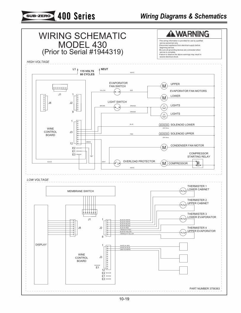
400 Series400 Series Wiring Diagrams & Schematics
10-19
severe electrical shock.
-Failure to observe the above warnings may result in
service is complete.
-Be sure all grounding devices are connected when
beginning service.
-Disconnect appliance from electrical supply before
service personnel only.
-This wiring information is provided for use by qualified
PART NUMBER 3756363
E2
E3
E1
E3E1
295 Ohms
295 Ohms
LIGHTS
LOWER
UPPER
M
MEVAPORATOR FAN MOTORS
LIGHTS
MCOMPRESSOR
STARTING RELAY
SOLENOID LOWER
SOLENOID UPPER
CONDENSER FAN MOTOR
NEUT
WHITE
REDYELLOW
FAN SWITCH
EVAPORATOR
L1
60 CYCLES
1J1
115 VOLTS
ORANGE
BLUE
ORANGE
BROWN
LIGHT SWITCH
PINK
J2
8
1
GREEN
J3
12
J8
CONTROL
BOARD
WINE
M COMPRESSOR
THERMISTER 2
UPPER CABINET
THERMISTER 3
LOWER EVAPORATOR
THERMISTER 1
LOWER CABINET
THERMISTER 4
UPPER EVAPORATOR
WHITE
GRAY
MEMBRANE SWITCH
8
1 WHITE W/ RED
WHITE W/ BLUE
ORANGE W/ YELLOW
BLUE W/ YELLOW
ORANGE W/ RED
BLUE W/ WHITE
BLUE W/ WHITE
BLUE W/ BLACK
BLUE W/ BLACK
BLUE W/ RED
E2
12
GRAY W/ WHITE
J8
WINE
BOARD
E1
CONTROL J3
J2
J1 1
OVERLOAD PROTECTORBLACK
DISPLAY
LOW VOLTAGE
HIGH VOLTAGE
WIRING SCHEMATICMODEL 430
(Prior to Serial #1944319)
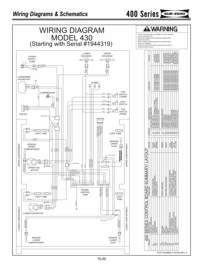
400 Series400 SeriesWiring Diagrams & Schematics
10-20
PART NUMBER 3757520 REV. A
11
12
10 89 67 5 234 1
BOARD
WINE
CONTROL
368 7 5 4 12
LIGHT
SWITCH
SWITCH
FAN
WHITE
GRAY
1 BLACK
2 WHITE
GREEN
L2L1
PLAIN
RIBBED
3 GREEN
1 GRAY
2 WHITE
TESTER
POWER
SUPPLY
CORD
LOWER
SOLENOID SOLENOID
UPPER
BL
UE
1
WH
ITE
2
PIN
K 1
WH
ITE
2
ALARM
BROWN
PINK
PINK
ORANGE
TESTER
OR
AN
GE
W/ Y
ELLO
W 4
BL
UE
W/ Y
EL
LO
W 3
OR
AN
GE
W/
RE
D 2
BL
UE
W/
RE
D 1
LIGHT TUBE
SENSOR
UPPER
EVAP
OR
AN
GE
W/ Y
EL
LO
W 1
BL
UE
W/ Y
EL
LO
W 2
LIGHT
TUBE
LIGHT TUBE
LIGHT TUBE
LOWER FAN MOTOR
LOWER
EVAP
SENSORSENSOR
LOWER
COMPARTMENT
SENSOR
UPPER
COMPARTMENT
UPPER FAN
MOTOR
BL
UE
W/ W
HIT
E
BL
UE
W/ W
HIT
E
BL
UE
W/ W
HIT
E 1
BL
UE
W/ W
HIT
E 2
BL
UE
W/
RE
D 5
OR
AN
GE
W/ R
ED
6
2 BLUE W/ BLACK
3 BLUE W/ BLACK
BL
UE
W/
BL
AC
K
BL
UE
W/
BL
AC
K
1 W
HIT
E W
/ R
ED
2 W
HIT
E W
/ B
LU
E
3 G
RA
Y W
/ W
HIT
E
6 B
LU
E
8 P
INK
10 WHITE
WH
ITE
WH
ITE
BL
UE
GR
EE
N
ORANGE
WHITE
WH
ITE
OR
AN
GE
OR
AN
GE
PIN
K
7 ORANGE
OR
AN
GE
W/ R
ED
BL
UE
W/
RE
D
WH
ITE
WH
ITE
WH
ITE
WHITE
GRAY
GR
AY
WH
ITE
WH
ITE
WH
ITE
WH
ITE
HEATSHRINK
HEATSHRINK
HEATSHRINK
GR
AY
GR
EE
N 1
2
2 WHITE
1 RED
3 GREEN
2 WHITE
3 GREEN
1 RED
GREEN
GREEN
UP
PE
R C
OM
PA
RT
ME
NT
UP
PE
R C
OM
PA
RT
ME
NT
LO
WE
R C
OM
PA
RT
ME
NT
LO
WE
R C
OM
PA
RT
ME
NT
HEATSHRINK
CONDENSER
FAN MOTOR
COMPRESSOR
4 OPEN
BR
OW
N
GRAY
BLACK
BLUE
SWITCHBLUE
FAN
1 BLUE
BL
UE
ORANGE
UPPER
LOWER
CIR
CU
IT
P P2
P3
J3
J2
P P2
P3
P4
P5
P6
P8
P7
40
0 S
ER
IES
CO
NT
RO
L B
OA
RD
SU
MM
AR
Y/ L
AY
OU
TC
IRC
UIT
E E2
E3
P12
J3
P10
P11
P9
P6
P8
P7 P4
P5
LIG
HT
SP
OW
ER
S L
IGH
TS
BR
OW
NP
OW
ER
S C
OM
PR
ES
SO
RP
OW
ER
IN
TO
BO
AR
D120 V
OLT
CIR
CU
ITS
CO
MP
RE
SS
OR
DE
SC
RIP
TIO
N
PO
WE
R IN
FU
NC
TIO
N
BL
AC
KG
RA
Y
CO
LO
R
PO
WE
RS
EV
AP
OR
AT
OR
FA
NS
CO
OLS
UP
PE
R C
OM
PA
RT
ME
NT
CO
OLS
LO
WE
R C
OM
PA
RT
ME
NT
ON
WH
EN
LIG
HT
S O
N 1
00%
NE
UT
RA
L IN
TO
BO
AR
D
EA
RT
H G
RO
UN
D
EM
PT
Y
GR
OU
ND
NE
UT
RA
LE
MP
TY
EV
AP
OR
AT
OR
FA
NS
LIG
HT
S O
VE
RR
IDE
LO
WE
R S
OLE
NO
ID V
ALV
E
UP
PE
R S
OLE
NO
ID V
ALV
E
EM
PT
Y
GR
EE
N
WH
ITE
BLU
EO
RA
NG
EP
INK
YE
LLO
W
ALA
RM
CIR
CU
IT-N
OR
MA
LLY
CLO
SE
DF
OR
HO
ME
ALA
RM
SW
HT
/BLU
EF
OR
HO
ME
ALA
RM
S
LO
W V
OLT
AG
E C
IRC
UIT
SA
LA
RM
CIR
CU
IT
DE
SC
RIP
TIO
NF
UN
CT
ION
CO
LO
R
WH
T/R
ED
FO
R H
OM
E A
LA
RM
S
SE
NS
ES
TE
MP
ER
AT
UR
E
ALA
RM
CIR
CU
IT-O
PE
N
UP
PE
R C
AB
INE
T
LO
WE
R C
AB
INE
TLO
WE
R C
AB
INE
T
TH
ER
MIS
TE
R C
IRC
UIT
S
UP
PE
R C
AB
INE
TLO
WE
R E
VA
PO
RA
TO
RLO
WE
R E
VA
PO
RA
TO
R
UP
PE
R E
VA
PO
RA
TO
RU
PP
ER
EV
AP
OR
AT
OR
GR
AY
/WH
T
BLU
E/W
HIT
EB
LU
E/W
HIT
EB
LU
E/B
LA
CK
BLU
E/B
LA
CK
BLU
E/R
ED
OR
AN
GE
/RE
D
OR
AN
GE
/YE
LL
BLU
E/Y
ELLO
W
ALA
RM
CIR
CU
IT-N
OR
MA
LLY
OP
EN
SE
NS
ES
TE
MP
ER
AT
UR
ES
EN
SE
S T
EM
PE
RA
TU
RE
SE
NS
ES
TE
MP
ER
AT
UR
ES
EN
SE
S T
EM
PE
RA
TU
RE
SE
NS
ES
TE
MP
ER
AT
UR
ES
EN
SE
S T
EM
PE
RA
TU
RE
SE
NS
ES
TE
MP
ER
AT
UR
E
E2E1
E3
-This wiring information is provided for use by qualified
service personnel only.
-Disconnect appliance from electrical supply before
beginning service.
-Be sure all grounding devices are connected when
service is complete.
-Failure to observe the above warnings may result in
severe electrical shock.
WIRING DIAGRAMMODEL 430
(Starting with Serial #1944319)
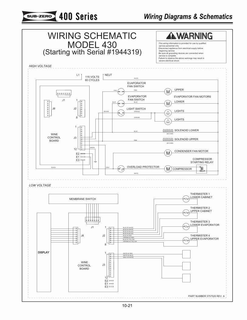
400 Series400 Series Wiring Diagrams & Schematics
10-21
PART NUMBER 3757520 REV. A
DISPLAY
BLACK OVERLOAD PROTECTOR
1J1
J2
J3CONTROL
BOARD
WINE
J8
GRAY W/ WHITE
12E2
BLUE W/ RED
BLUE W/ BLACK
BLUE W/ BLACK
BLUE W/ WHITE
BLUE W/ WHITE
ORANGE W/ RED
BLUE W/ YELLOW
ORANGE W/ YELLOW
WHITE W/ BLUE
WHITE W/ RED1
8
MEMBRANE SWITCH
GRAY
WHITE
UPPER EVAPORATOR
THERMISTER 4
LOWER CABINET
THERMISTER 1
LOWER EVAPORATOR
THERMISTER 3
UPPER CABINET
THERMISTER 2
COMPRESSOR
WINE
BOARD
CONTROL
J8
12
J3
GREEN
1
8
J2
PINK
LIGHT SWITCHBROWN
ORANGE
BLUE
ORANGE
115 VOLTS
J1 1
60 CYCLES
L1
EVAPORATOR
FAN SWITCH
PINK PINK
WHITE
NEUT
CONDENSER FAN MOTOR
SOLENOID UPPER
SOLENOID LOWER
STARTING RELAY
COMPRESSOR
LIGHTS
EVAPORATOR FAN MOTORS
UPPER
LOWER
LIGHTS
295 OHMS
295 OHMS
E1E3
E1
E3
E2
BLUE BLUE
FAN SWITCH
EVAPORATOR
M
M
M
M
severe electrical shock.
-Failure to observe the above warnings may result in
service is complete.
-Be sure all grounding devices are connected when
beginning service.
-Disconnect appliance from electrical supply before
service personnel only.
-This wiring information is provided for use by qualified
LOW VOLTAGE
HIGH VOLTAGE
WIRING SCHEMATICMODEL 430
(Starting with Serial #1944319)
400 Series400 SeriesWiring Diagrams & Schematics
10-22