Embed Size (px)
Citation preview
Version 1.0 October 2021 Page 1
TECHNICAL SPECIFICATION 2 TILED ROOF UPGRADES CYCLONE SEROJA RECOVERY AND RESILIENCE GRANTS PROGRAM
…. The Recovery and Resilience Grants Program offers grants of up to $20,000 to help insured residents impacted by Severe Tropical Cyclone Seroja build back better against future cyclones.
This technical specification provides information for builders and designers to understand the minimum design, compliance and evidence requirements for tiled roof upgrade works through the Resilience Grant. Non-compliance with the requirements may deem the Resilience Grant application ineligible.
This specification includes the following sections.
1. Scope of works 2
2. Tie-down of roof structure to walls 3
3. Sarking 8
4. Batten to rafter or truss connections 8
5. Roof Tiles 9
6. Evidence Requirements 10
Appendix A: Wind Classifications and Internal Pressure 12
Appendix B Resources 15
Fact sheets and technical specifications are also available for the following eligible works under the Recovery and Resilience Grants Program:
• Structural upgrades for a sheet metal roof.
• Replacing existing hollow core or semi-solid exterior doors with solid timber doors.
• Replacing an existing garage door with a cyclonic wind-rated garage door.
• Installing debris screens or cyclone rated shutters to windows.
IMPORTANT NOTE FOR CONTRACTORS – EVIDENCE REQUIREMENTS
The Recovery and Resilience Grant will only be paid when the required evidence is provided, as described in this specification. Failure to provide the required evidence will result in the grant application being ineligible
TECHNICAL SPECIFICATION 2 - TILED ROOF UPGRADES
Version 1.0 October 2021 Page 2
1. Scope of works
1.1 Design requirements
All eligible building elements must be designed and certified to a C wind classification equivalent to the current N wind classification of the site, as shown at Table 1.1 below. Table 1.1 – Applicable C Wind Classification for Resilience Upgrades
Current ‘N’ Wind Classification
Recommended ‘C’ Wind Classification
N2 N3
C1
N4 C2
The current wind classification for the site must be determined by a qualified engineer with reference to AS 4055 or AS/NZS 1170.2 as appropriate. Eligible roof upgrade works must involve all of the following four elements in order to ensure a secure chain of structural connections that can resist uplift.
1. Upgrade tie-down of roof structure to wall to C wind classification requirements. 2. Upgrade batten to rafter/truss connection to C wind classification requirements. 3. Install or repair sarking to entire roof area. 4. Mechanical fastening of all roof tiles and ridges to battens appropriate to wind classification.
This specification provides information of typical details and requirements for the above elements taken from National Construction Code (NCC) referenced documents. The examples do not include every available option, detail every member in the structural system that resist uplift from wind loads, or provide solutions for complex designs or buildings that do not satisfy the geometric limitations of AS 4055, AS 1684 or the National Association of Steel-framed Housing (NASH) standard. Expert engineering advice may be required to determine a compliant solution.
1.2 Different Requirements for Sheet Roofs and Tiled Roofs
The tie-down requirements for a sheet roof exceed the requirements for tile roofs because of the additional resistance arising from the weight of a tiled roof. The Specification for Tiled Roofs does not apply to works involving the replacement of a tile roof with a metal sheet roof, which must comply with the fixing requirements specified in the Technical Specification 1 - Sheet Metal Roof Upgrades. (Also refer to Building and Energy information: Changing your roof cover – things you need to know and General Inspection Report 5 – Investigation into reroofing of buildings)
1.3 Approvals
Approval of funding under the Recovery and Resilience Grants Program does not constitute a regulatory or local government approval to undertake works. Contractors must obtain necessary approvals and licenses for planning, demolition, and building from the local government prior to commencing any works on site. Note that structural works and replacement of a roof usually requires a building permit.
TECHNICAL SPECIFICATION 2 - TILED ROOF UPGRADES
Version 1.0 October 2021 Page 3
1.4 Applicable Standards
The information in these specifications must be used in conjunction with the requirements under building legislation in Western Australia. All building work must be designed and constructed in accordance with the current National Construction Code (NCC). The following NCC referenced documents apply to these works and are referenced in this specification:
• AS 4055 Wind loads for housing
• AS 1170.2 Structural Design Actions: Part 2, Wind Actions
• AS 1483.3 Timber Framing Code, Cyclonic Areas
• AS 4773.1 Masonry design in small buildings
• AS 1250 The Use of Steel in Structures
Reference is also made to the National Association of Steel-framed Housing (NASH) Standard - Residential and Low-rise Steel Framing Part 1: Design Criteria.
2. Tie-down of roof structure to walls
2.1 Girder trusses and strutting beams
The wind uplift forces on girder trusses, which support other trusses, are significantly higher than those on standard trusses due to the larger roof area supported by girder trusses. Likewise, strutting beams carry larger loads than normal rafters. All tie-downs through wall and floor systems below girder trusses or strutting beams must be sized for the higher uplift forces associated with the relevant C wind classification (see Table 1.1). This information must be provided by the truss designer or the design engineer in the form of a certified drawings.
2.2 Timber roof frame to timber-framed walls
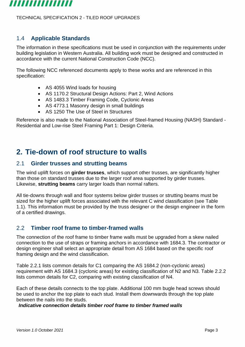
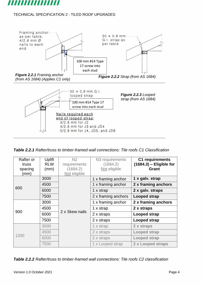
The connection of the roof frame to timber frame walls must be upgraded from a skew nailed connection to the use of straps or framing anchors in accordance with 1684.3. The contractor or design engineer shall select an appropriate detail from AS 1684 based on the specific roof framing design and the wind classification. Table 2.2.1 lists common details for C1 comparing the AS 1684.2 (non-cyclonic areas) requirement with AS 1684.3 (cyclonic areas) for existing classification of N2 and N3. Table 2.2.2 lists common details for C2, comparing with existing classification of N4. Each of these details connects to the top plate. Additional 100 mm bugle head screws should be used to anchor the top plate to each stud. Install them downwards through the top plate between the nails into the studs. Indicative connection details timber roof frame to timber framed walls
TECHNICAL SPECIFICATION 2 - TILED ROOF UPGRADES
Version 1.0 October 2021 Page 4
Figure 2.2.1 Framing anchor (from AS 1684) (Applies C1 only)
Figure 2.2.2 Strap (from AS 1684)
Figure 2.2.3 Looped strap (from AS 1684)
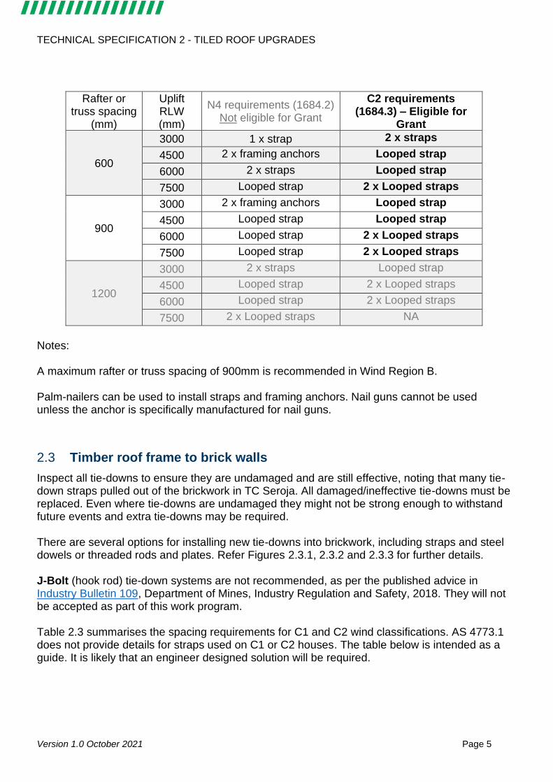
Table 2.2.1 Rafter/truss to timber-framed wall connections: Tile roofs C1 Classification
Rafter or truss
spacing (mm)
Uplift RLW (mm)
N2 requirements
(1684.2) Not eligible
N3 requirements (1684.2)
Not eligible
C1 requirements (1684.3) – Eligible for
Grant
600
3000
2 x Skew nails
1 x framing anchor 1 x galv. strap
4500 1 x framing anchor 2 x framing anchors
6000 1 x strap 2 x galv. straps
7500 2 x framing anchors Looped strap
900
3000 1 x framing anchor 2 x framing anchors
4500 1 x strap 2 x straps
6000 2 x straps Looped strap
7500 2 x straps Looped strap
1200
3000 1 x strap 2 x straps
4500 2 x straps Looped strap
6000 2 x straps Looped strap
7500 1 x Looped strap 2 x Looped straps
Table 2.2.2 Rafter/truss to timber-framed wall connections: Tile roofs C2 classification
100 mm #14 Type 17 screw into each stud
100 mm #14 Type 17 screw into
each stud
TECHNICAL SPECIFICATION 2 - TILED ROOF UPGRADES
Version 1.0 October 2021 Page 5
Rafter or truss spacing
(mm)
Uplift RLW (mm)
N4 requirements (1684.2) Not eligible for Grant
C2 requirements (1684.3) – Eligible for
Grant
600
3000 1 x strap 2 x straps
4500 2 x framing anchors Looped strap
6000 2 x straps Looped strap
7500 Looped strap 2 x Looped straps
900
3000 2 x framing anchors Looped strap
4500 Looped strap Looped strap
6000 Looped strap 2 x Looped straps
7500 Looped strap 2 x Looped straps
1200
3000 2 x straps Looped strap
4500 Looped strap 2 x Looped straps
6000 Looped strap 2 x Looped straps
7500 2 x Looped straps NA
Notes: A maximum rafter or truss spacing of 900mm is recommended in Wind Region B. Palm-nailers can be used to install straps and framing anchors. Nail guns cannot be used unless the anchor is specifically manufactured for nail guns.
2.3 Timber roof frame to brick walls
Inspect all tie-downs to ensure they are undamaged and are still effective, noting that many tie-down straps pulled out of the brickwork in TC Seroja. All damaged/ineffective tie-downs must be replaced. Even where tie-downs are undamaged they might not be strong enough to withstand future events and extra tie-downs may be required. There are several options for installing new tie-downs into brickwork, including straps and steel dowels or threaded rods and plates. Refer Figures 2.3.1, 2.3.2 and 2.3.3 for further details. J-Bolt (hook rod) tie-down systems are not recommended, as per the published advice in Industry Bulletin 109, Department of Mines, Industry Regulation and Safety, 2018. They will not be accepted as part of this work program. Table 2.3 summarises the spacing requirements for C1 and C2 wind classifications. AS 4773.1 does not provide details for straps used on C1 or C2 houses. The table below is intended as a guide. It is likely that an engineer designed solution will be required.
TECHNICAL SPECIFICATION 2 - TILED ROOF UPGRADES
Version 1.0 October 2021 Page 6
Table 2.3 – Example of tie-down spacing requirements (from AS 4773.1)
Uplift load width (ULW) (mm)
Wind Region B (N2 / N3 / N4) requirements (mm)
Not eligible for grant
Recommended spacing to meet eligibility requirements
C1 wind classification
C2 wind classification
Embedment depth >900 mm
Embedment depth >2000 mm
3000 1200/1200/1200 1200 1200
4500 1200/1200/1200 1200 1050
6000 1200/1200/1200 1200 900
7500 1200/1200/ NA 1050 NA
8000 1200 / NA / NA 900 NA
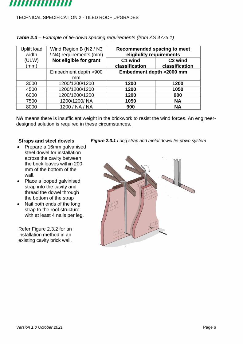
NA means there is insufficient weight in the brickwork to resist the wind forces. An engineer-designed solution is required in these circumstances. Straps and steel dowels
• Prepare a 16mm galvanised steel dowel for installation across the cavity between the brick leaves within 200 mm of the bottom of the wall.
• Place a looped galvinised strap into the cavity and thread the dowel through the bottom of the strap
• Nail both ends of the long strap to the roof structure with at least 4 nails per leg.
Refer Figure 2.3.2 for an installation method in an existing cavity brick wall.
Figure 2.3.1 Long strap and metal dowel tie-down system
TECHNICAL SPECIFICATION 2 - TILED ROOF UPGRADES
Version 1.0 October 2021 Page 7
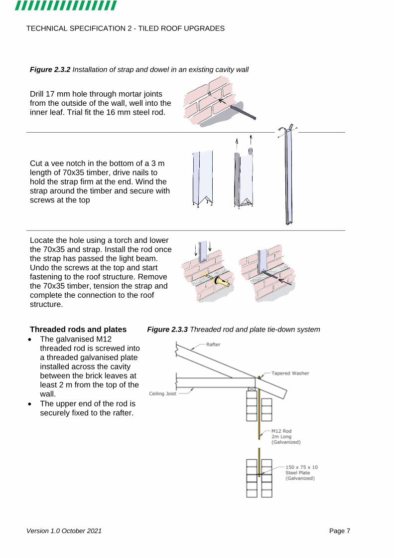
Figure 2.3.2 Installation of strap and dowel in an existing cavity wall
Drill 17 mm hole through mortar joints from the outside of the wall, well into the inner leaf. Trial fit the 16 mm steel rod.
Cut a vee notch in the bottom of a 3 m length of 70x35 timber, drive nails to hold the strap firm at the end. Wind the strap around the timber and secure with screws at the top
Locate the hole using a torch and lower the 70x35 and strap. Install the rod once the strap has passed the light beam. Undo the screws at the top and start fastening to the roof structure. Remove the 70x35 timber, tension the strap and complete the connection to the roof structure.
Threaded rods and plates
• The galvanised M12 threaded rod is screwed into a threaded galvanised plate installed across the cavity between the brick leaves at least 2 m from the top of the wall.
• The upper end of the rod is securely fixed to the rafter.
Figure 2.3.3 Threaded rod and plate tie-down system
TECHNICAL SPECIFICATION 2 - TILED ROOF UPGRADES
Version 1.0 October 2021 Page 8
2.4 Engineered roof designs / alternative solutions
Engineered roof structures and other structures that do not fit within standard design tables will require certified engineers drawing demonstrating that the connections meet the uplift requirements for the relevant C wind classification (see Table 1.1).
3. Sarking
Sarking is recommended across the whole roof, prior to the installation of roof battens. Minimum sarking grade: Heavy duty (high wind areas) Recommended sarking grade: Extra heavy duty (safety/fall arrest)
4. Batten to rafter or truss connections
4.1 Batten to rafter or truss connections in timber framing
Select an appropriate fixing detail from AS 1250, using:
• details for C1 wind classifications for existing N2 or N3 classifications
• details for C2 wind classification for existing N4 classification.
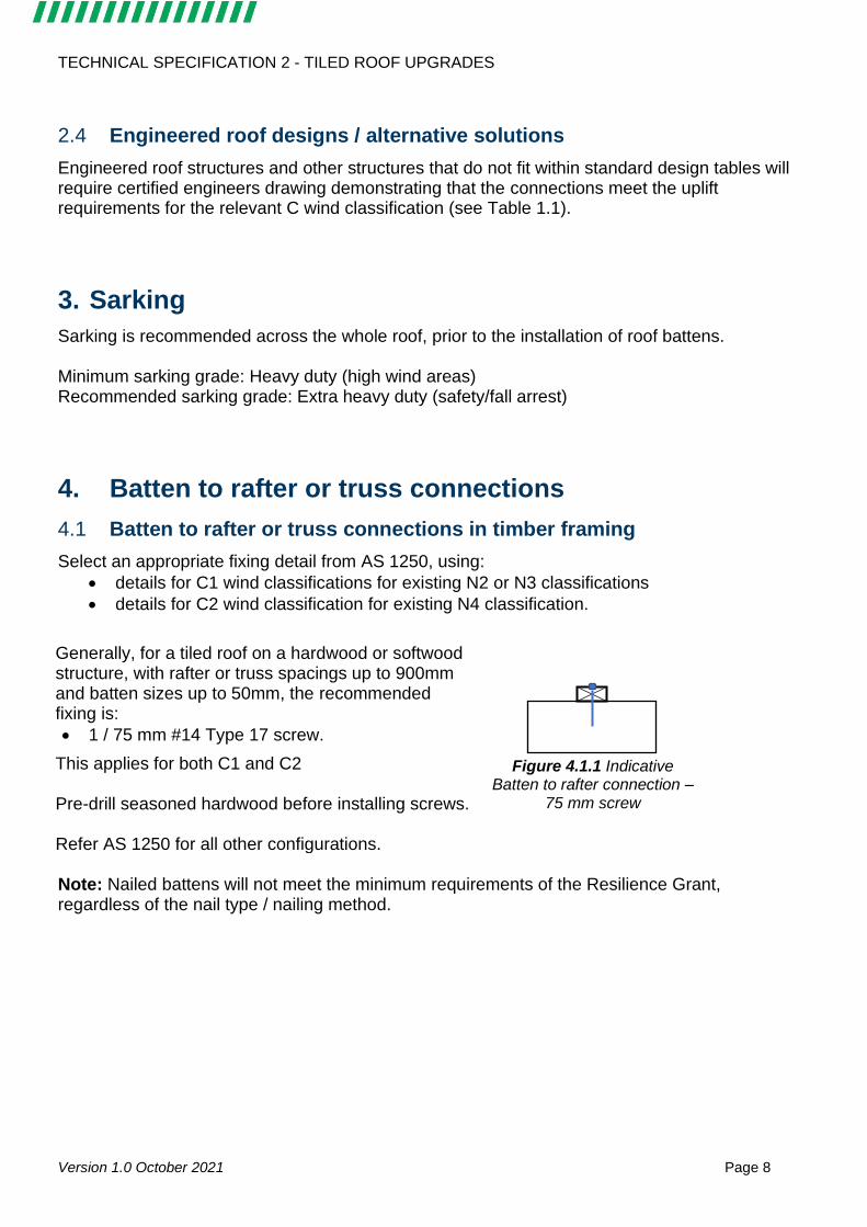
Generally, for a tiled roof on a hardwood or softwood structure, with rafter or truss spacings up to 900mm and batten sizes up to 50mm, the recommended fixing is:
• 1 / 75 mm #14 Type 17 screw.
This applies for both C1 and C2 Pre-drill seasoned hardwood before installing screws. Refer AS 1250 for all other configurations.
Figure 4.1.1 Indicative
Batten to rafter connection –75 mm screw
Note: Nailed battens will not meet the minimum requirements of the Resilience Grant, regardless of the nail type / nailing method.
TECHNICAL SPECIFICATION 2 - TILED ROOF UPGRADES
Version 1.0 October 2021 Page 9
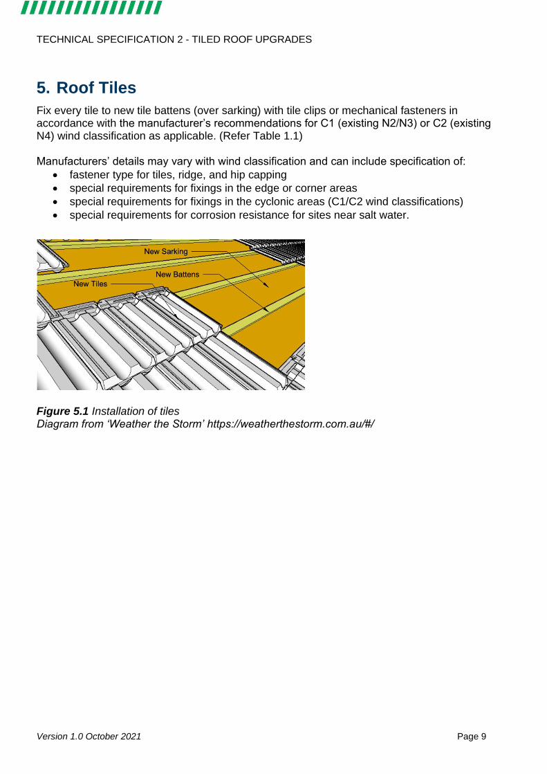
5. Roof Tiles
Fix every tile to new tile battens (over sarking) with tile clips or mechanical fasteners in accordance with the manufacturer’s recommendations for C1 (existing N2/N3) or C2 (existing N4) wind classification as applicable. (Refer Table 1.1) Manufacturers’ details may vary with wind classification and can include specification of:
• fastener type for tiles, ridge, and hip capping
• special requirements for fixings in the edge or corner areas
• special requirements for fixings in the cyclonic areas (C1/C2 wind classifications)
• special requirements for corrosion resistance for sites near salt water.
Figure 5.1 Installation of tiles Diagram from ‘Weather the Storm’ https://weatherthestorm.com.au/#/
TECHNICAL SPECIFICATION 2 - TILED ROOF UPGRADES
Version 1.0 October 2021 Page 10
6. Evidence Requirements
The following evidence must be provided to support an application for a Resilience Grant. 1. All necessary building approvals / licenses for structural works
2. Builders / contractors licenses
3. Tax Invoice with detail of works and ABN/ACN
4. Wind rating assessment and classification by certified engineer
5. Certified roof framing plans/details/schedule with reference to one or more of the following
standards as appropriate for the construction type. Details used in the plans and specifications must be appropriate for the relevant C wind classification (see Table 1.1):
• AS 4055 Wind loads for housing
• AS 1170.2 Structural Design Actions: Part 2, Wind Actions
• AS 1483.3 Timber Framing Code, Cyclonic Areas
• AS 4773.1 Masonry design in small buildings
• AS 1250 The Use of Steel in Structures
• National Association of Steel-framed Housing (NASH) Standard - Residential and Low-rise Steel Framing Part 1: Design Criteria
6. Site photos of works in progress and complete structure prior to insulation/tiles, including
the following connections:
• Batten to rafter connection (photos showing the connections in different parts of the roof)
• Roof or truss to wall connections (photos showing the connections at the top of the wall where the spacing between the connections can be seen using a tape measure for reference)
• Bottom wall connections – for Brick Walls only (photos of the bottom of the connection showing dowels or plates being installed)
• Batten spacing (photos of a tape measure across battens showing the spacing between battens)
• Roof Fastener Spacing (photos showing roof panels where the fasteners can clearly be seen)
• Roof or Truss Tie-down to wall structure and beams
7. Site photos of tile fixings
8. Site photos showing completed works
9. Signed Resilience Works Completion Form
Note: Photos should be taken from different positions showing different perspectives and angles.
TECHNICAL SPECIFICATION 2 - TILED ROOF UPGRADES
Version 1.0 October 2021 Page 11
Requirements for Photographic Evidence
Photographic evidence must clearly show the works in context and include global positioning system (GPS) coordinates and date information so that assessors can verify the location of the works. Most, but not all, electronic devices include GPS and date metadata with photos. Contractors should submit an initial photo to the Grants team of the front of the dwelling when works are commencing on site to enable the metadata / location of the works to be verified. Photos should be taken regularly as works proceed to provide a record of the works as a whole. In particular any upgrades and connections that will be concealed by later works must be photographed prior to concealment. Costs associated with uncovering concealed works may be borne by the Contractor. The following photos should be taken throughout the works and submitted regularly:
• photos from the ground showing the building itself and works in progress
• photos taken on a ladder or on the roof showing the installation of upgraded connections across the roof area
• detail photos demonstrating a sample of connections
Contractors are encouraged to speak regularly with the Recovery and Resilience Grants team to ensure their photos comply with the evidence requirements.
TECHNICAL SPECIFICATION 2 - TILED ROOF UPGRADES
Version 1.0 October 2021 Page 12
Appendix A: Wind Classifications and Internal Pressure
Wind Regions
AS 4055 (the Australian wind loading Standard for houses) divides Australia into four Wind Regions: A, B, C and D. Wind Regions A and B have N (non-cyclonic) wind classifications and Wind Regions C and D have C (cyclonic) wind classifications.
• Wind region A design winds are associated with severe thunderstorms, large frontal systems or significantly weakened tropical cyclones.
• Wind region B design winds are associated with severe thunderstorms, or tropical cyclones.
• Wind region C design winds are associated with severe tropical cyclones as they cross the coast.
• Wind region D design winds are associated with the most severe tropical cyclones.
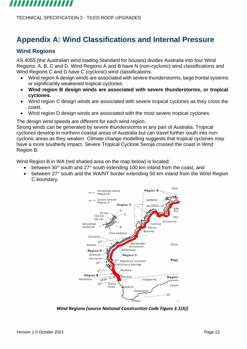
The design wind speeds are different for each wind region. Strong winds can be generated by severe thunderstorms in any part of Australia. Tropical cyclones develop in northern coastal areas of Australia but can travel further south into non-cyclonic areas as they weaken. Climate change modelling suggests that tropical cyclones may have a more southerly impact. Severe Tropical Cyclone Seroja crossed the coast in Wind Region B. Wind Region B in WA (red shaded area on the map below) is located:
• between 30° south and 27° south extending 100 km inland from the coast, and
• between 27° south and the WA/NT border extending 50 km inland from the Wind Region C boundary.
Wind Regions (source National Construction Code Figure 3.1(A))
TECHNICAL SPECIFICATION 2 - TILED ROOF UPGRADES
Version 1.0 October 2021 Page 13
Within each Wind Region, different wind classifications are applied based on the size and exposure of the building. AS 4055 is used by designers to determine the wind classification for most houses. Wind loads for larger houses must be evaluated using AS/NZS 1170.2. Wind classifications/wind loadings are used to design and specify the tie-downs required in the roof structure and walls, roof cladding and fixing details, bracing details, and windows and wall cladding.
• Many houses in Wind Region B will be assigned an N3 wind classification.
• Only houses surrounded by many other houses and not on a hill can have an N2 wind classification.
• Houses in a more exposed location with a good view may be classified as N4.
To be eligible for the Resilience Grant, the construction details have to comply with the relevant C wind classification – see Table 1.1.
Internal pressure
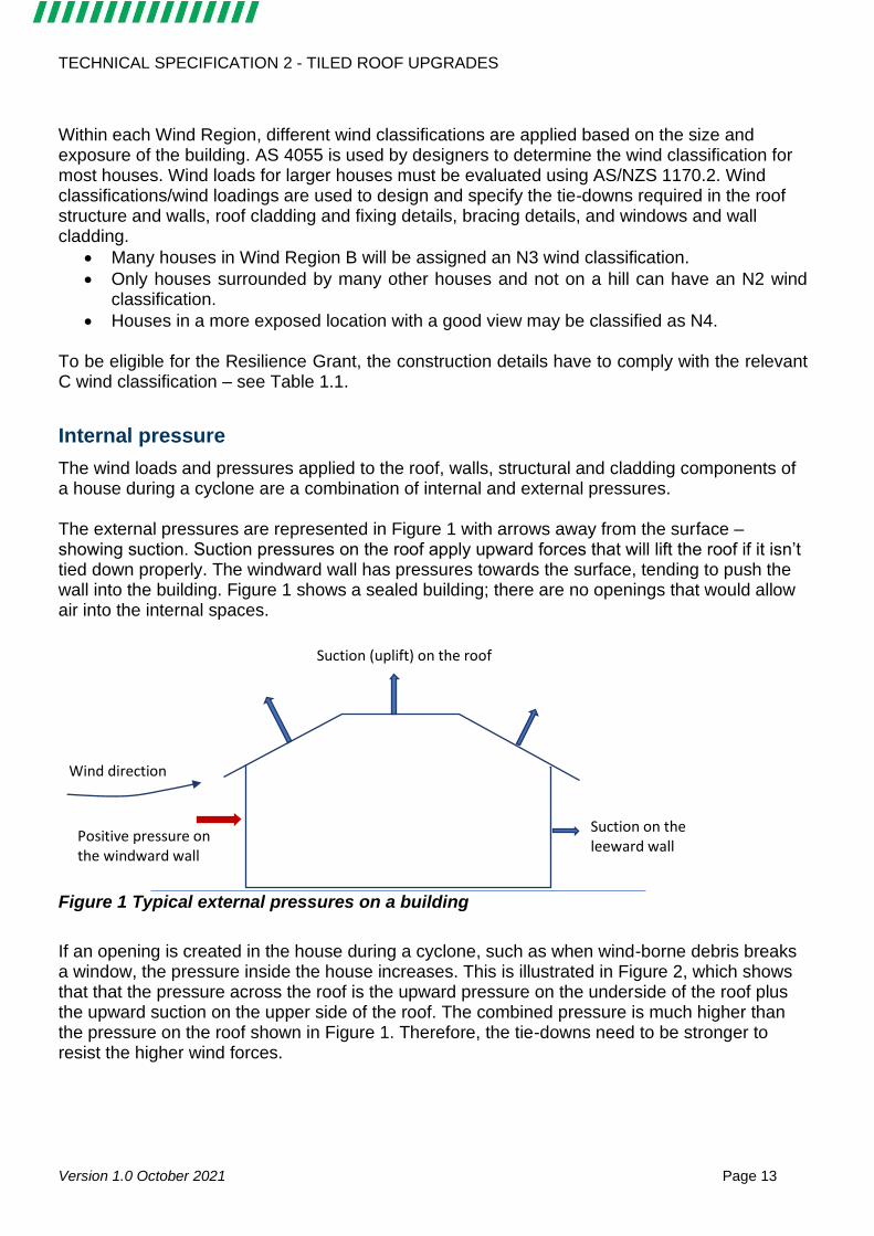
The wind loads and pressures applied to the roof, walls, structural and cladding components of a house during a cyclone are a combination of internal and external pressures. The external pressures are represented in Figure 1 with arrows away from the surface – showing suction. Suction pressures on the roof apply upward forces that will lift the roof if it isn’t tied down properly. The windward wall has pressures towards the surface, tending to push the wall into the building. Figure 1 shows a sealed building; there are no openings that would allow air into the internal spaces.
Figure 1 Typical external pressures on a building
If an opening is created in the house during a cyclone, such as when wind-borne debris breaks a window, the pressure inside the house increases. This is illustrated in Figure 2, which shows that that the pressure across the roof is the upward pressure on the underside of the roof plus the upward suction on the upper side of the roof. The combined pressure is much higher than the pressure on the roof shown in Figure 1. Therefore, the tie-downs need to be stronger to resist the higher wind forces.
Suction (uplift) on the roof
Positive pressure on the windward wall
Suction on the leeward wall
Wind direction

TECHNICAL SPECIFICATION 2 - TILED ROOF UPGRADES
Version 1.0 October 2021 Page 14
Figure 2 Typical internal pressures on a building with an opening on a windward wall
Houses in Wind Region B are typically designed for low internal pressure. As a result, many roof tie-downs were not strong enough to resist the high internal pressures created when a door or window was broken by wind-borne debris or wind pressure during TC Seroja, and many roofs were lost. The purpose of the grant program is to upgrade houses so they are stronger for future storms.
Suction (uplift) on the roof
Positive pressure on the windward wall
Suction on the leeward wall
Wind direction
Wind enters through broken window and increases pressure on underside of roof
TECHNICAL SPECIFICATION 2 - TILED ROOF UPGRADES
Version 1.0 October 2021 Page 15
Appendix B Resources
Building and Energy
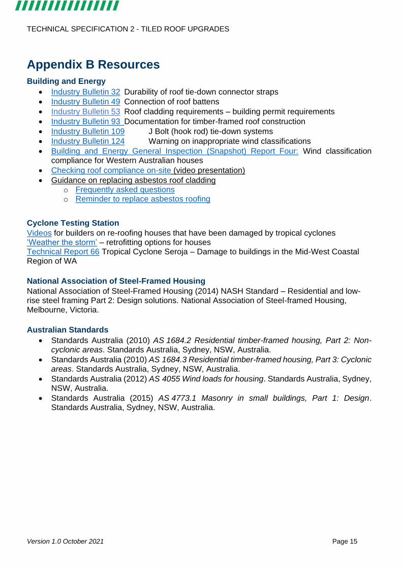
• Industry Bulletin 32 Durability of roof tie-down connector straps
• Industry Bulletin 49 Connection of roof battens
• Industry Bulletin 53 Roof cladding requirements – building permit requirements
• Industry Bulletin 93 Documentation for timber-framed roof construction
• Industry Bulletin 109 J Bolt (hook rod) tie-down systems
• Industry Bulletin 124 Warning on inappropriate wind classifications
• Building and Energy General Inspection (Snapshot) Report Four: Wind classification compliance for Western Australian houses
• Checking roof compliance on-site (video presentation)
• Guidance on replacing asbestos roof cladding o Frequently asked questions o Reminder to replace asbestos roofing
Cyclone Testing Station
Videos for builders on re-roofing houses that have been damaged by tropical cyclones ‘Weather the storm’ – retrofitting options for houses Technical Report 66 Tropical Cyclone Seroja – Damage to buildings in the Mid-West Coastal Region of WA
National Association of Steel-Framed Housing
National Association of Steel-Framed Housing (2014) NASH Standard – Residential and low-rise steel framing Part 2: Design solutions. National Association of Steel-framed Housing, Melbourne, Victoria.
Australian Standards
• Standards Australia (2010) AS 1684.2 Residential timber-framed housing, Part 2: Non-cyclonic areas. Standards Australia, Sydney, NSW, Australia.
• Standards Australia (2010) AS 1684.3 Residential timber-framed housing, Part 3: Cyclonic areas. Standards Australia, Sydney, NSW, Australia.
• Standards Australia (2012) AS 4055 Wind loads for housing. Standards Australia, Sydney, NSW, Australia.
• Standards Australia (2015) AS 4773.1 Masonry in small buildings, Part 1: Design. Standards Australia, Sydney, NSW, Australia.