Embed Size (px)
Citation preview

Page 1 of 19 CPS Energy Technical Specification AvR Power Plant Low Pressure Economizer Recirculation Pumps
Technical Specification
CPS Energy Arthur vonRosenberg Combined Cycle Plant
Low Pressure Economizer Recirculation Pumps
Rev. 0
9/25/2017

Page 2 of 19 CPS Energy Technical Specification AvR Power Plant Low Pressure Economizer Recirculation Pumps
Section A – Pump Requirements 1.0 General This specification covers the design, performance, and construction requirements for the Low Pressure Economizer Recirculation Pumps, located at the Arthur vonRosenburg combined cycle power plant, located at the Braunig Power station in San Antonio, TX. Performance and design requirements for this pump is shown in the Pump Specification Sheet at the end of this specification. Each pump and motor and all accessories shall be completely assembled prior to shipment. 2.0 Code Requirements All equipment and materials furnished under these requirements shall be designed and constructed in accordance with the latest applicable requirements of the standard specifications and codes of the Hydraulic Institute, ANSI, ASME, ASTM, ABMA, API, NEMA, IEEE, and other such regular published and accepted standards except where modified or supplemented by these requirements; and in accordance with the applicable requirements of the Federal “Occupational Safety and Health Standards.” In addition to the codes and standards mentioned above, the equipment shall be designed and constructed according to the following specific codes and standards:
Work In Accordance With
Pump design and fabrication ANSI/HI 1.1-1.5, American National
Standard for Centrifugal Pumps
Definitions of duplicate and identical pumps
ANSI/HI 1.1-1.5, American National Standard for Centrifugal Pumps
Design, construction, and dimensions of centerline mounted vertically split pumps
ANSI/API Standard 610
Design, construction, and dimensions of frame mounted end suction pumps
ANSI/ASME B73.1M
Life rating for antifriction bearings
ABMA (American Bearing Manufacturers Association) L-10
Personnel protection OSHA
3.0 Guarantees Guarantees shall be provided for pumps at the design conditions. The pumps shall be guaranteed to perform as indicated by the performance curves. The pumps shall be guaranteed to operate satisfactorily without pitting, cavitation, excessive vibration, or excessive noise at design conditions. The following shall be guaranteed within the tolerances permitted by the Hydraulic Institute Standards.
Capacity at the design point
Total head at the design point
NPSH values shown on the pump characteristic curves Efficiency (100 HP and larger only)

Page 3 of 19 CPS Energy Technical Specification AvR Power Plant Low Pressure Economizer Recirculation Pumps
Ability to operate in parallel under the design conditions if parallel operation capability is indicated on the General Service Horizontal Pumps Specification Sheets.
Ability to operate under all operating conditions from minimum continuous pump flow to maximum continuous pump run out flow
Minimum continuous pump flow shall be less than 40 percent of design flow
Maximum continuous pump run out flow. Maximum continuous pump run out flow shall be greater than 120 percent of design flow
Maximum pump shutoff head. Maximum pump shutoff head shall be greater than 110 percent of design head and less than 150 percent of design head.
The total dynamic pump head shall be a maximum at zero flow, continuously decreasing from zero flow to maximum continuous pump run out flow and include all losses through the pump and pump discharge.
Vibration or axial thrust transmitted from the pump to the drive through the coupling shall not exceed Hydraulic Institute limits from minimum to maximum continuous flow
Free of flashing and cavitation from minimum to maximum continuous flow
No critical speed within ±25 percent of the pump operating speed or reverse rotation speed
Ability to operate, without harmful effects, for extended periods of time at the minimum continuous pump flow
Impeller shall not be the maximum or minimum size for pump casing and the total dynamic head for the maximum impeller for the pump casing shall be at least 10 percent higher than design head
Pump design pressure shall be equal to the pump shutoff head plus the maximum suction pressure and applied to the pump casing, stuffing/seal box and pump connections on the casing.
4.0 Pump Accessories The Low Pressure Economizer Recirculation Pumps shall be furnished with the following accessory equipment. 4.1 Shaft Couplings Each pump shall be furnished with a shaft coupling. Shaft couplings, where applicable, shall be used between all drives and driven equipment. Couplings shall be attached to driver and driven shafts by press fits and keys. Shaft couplings shall be sized to transmit the maximum brake horsepower requirements of the driven equipment with a service factor of not less than two (2). Couplings on pumps with mechanical seals shall be spacer type couplings to permit replacement of the mechanical shaft seals without disturbing the drive motor.
4.2 Safety Guards
Safety guards shall be furnished for all exposed rotating shafts in accordance with the requirements listed below: Each guard shall be fabricated from ASTM A36 or A366 steel plate having a minimum thickness of 10BWG and designed for easy installation and removal. Necessary supports and accessories shall be furnished with each guard. Safety guards to be coated with same coating system as equipment base and pump casing.

Page 4 of 19 CPS Energy Technical Specification AvR Power Plant Low Pressure Economizer Recirculation Pumps
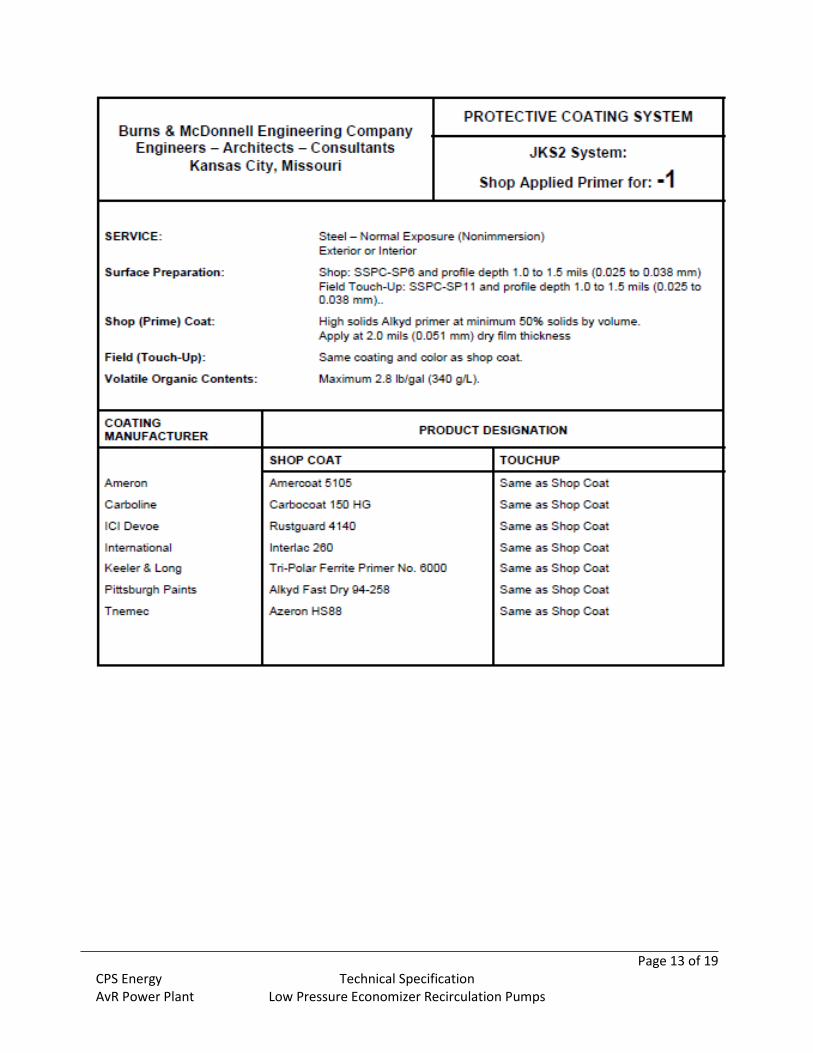
4.3 Equipment Bases All pumps shall be provided with a heavy cast iron or fabricated steel box type, full length base plate beneath the pump and motor. Motor mounting provisions shall be acceptable to the motor manufacturer. Base plates shall be designed to adequately support the equipment under all conditions without 100 percent grout fill inside the base plate frame. Bed plates shall be designed to take two (2) times API 610 nozzle loads in the grouted condition. A cast iron or welded steel base plate shall be provided for all rotating equipment which is to be installed on a concrete base. Each base plate shall support the unit and its drive assembly and shall be of a neat design with pads for anchoring the units. Base plates shall be provided with a raised lip all around and shall have a threaded drain connection. Provide sole plates as recommended or required by the equipment manufacturer. Equipment bases to be coated with same coating system as pump casing. Base should be constructed in such a manner that the suction elevation centerline measurement of the attached as-built drawing is maintained. If feasible, the discharge elevation centerline should be maintained as well. The base mounting holes shall match the as-built drawing, as this base is intended to be a direct replacement. 4.4 Minimum Flow Orifices Low Pressure Economizer Recirculation Pumps to be provided with minimum continuous flow orifices. Orifice sizes shall be based on the recommended minimum continuous flow for the associated pump. The orifices shall be supplied by the Supplier. The pump design capacity indicated on the Pumps Specification Sheet shall be increased by the amount of flow through the minimum continuous flow orifice so that the specified design flow at the specified design head is available to the system. The orifices shall be designed for installation between two raised face flanges in the recirculation piping, already installed in the field. 5.0 Equipment Coatings 5.1 Shop Coating All metallic surfaces subject to corrosion shall be protected by suitable coatings applied in the shop. Surfaces which will be inaccessible after assembly shall be protected for the life of the equipment. The surfaces shall be thoroughly cleaned and prepared in the shop prior to application of coatings. Internal surfaces shall not be blasted with steel shot. Exposed surfaces shall be finished smooth, thoroughly cleaned, and filled as necessary to provide a smooth uniform base for painting. Surfaces to be finish painted after installation, or requiring paint for corrosion protection until installation, shall be surface prepared and shop painted with one or more coats of top-coatable paint as hereinafter described. 5.3 Painting Shop coating systems for carbon steel equipment and other ferrous metal surfaces shall be as described on the indicated Coating System Data Sheets, included at the end of this specification. Where specific coating products and numbers are listed and/or when the listed products are not the equipment manufacturer’s standards, equal coating system products by other manufacturers may be acceptable and shall be submitted to the Owner for approval. All coatings to be applied in the shop shall be top-coatable (I.E., top-coatable such that additional field applied or field applied finish coatings can be applied without excessive effort or removal of the shop coating). Equipment manufacturer to indicate on the compliance submittals the shop applied coating generic type, name brand and number, surface preparation preformed, number of coats, and dry film thickness of each coat. All coatings shall be surface prepared,

Page 5 of 19 CPS Energy Technical Specification AvR Power Plant Low Pressure Economizer Recirculation Pumps
applied, cured, protected and the Work otherwise performed in strict accordance with the paint manufacturer’s printed recommendations. Pumps shall be cleaned, prepared, and prime coated in the shop prior to delivery. For equipment that will not be insulated and lagged, the equipment shall be shop prime coated using the appropriate shop applied primer data sheet attached (System: A-3, C-2, or C-3) dependent upon the expected service/operating temperature of the equipment. Subject to the Owner’s approval, the equipment manufacturer’s standard industry grade coating may be substituted on the basis that the equipment manufacturer’s standard coating meets the following minimum criteria: 1) suitable for the expected operating temperatures and conditions, 2) suitable for the intended location of the equipment within the plant, 3) minimum surface preparation of SSPC-SP6 blasted quality, 4) minimum of 6 mils DFT of coating system consisting of primer and epoxy topcoat of the same paint manufacturer. For equipment that will be insulated and lagged the equipment shall receive a minimum coating equal to the “Shop Applied Primer for: -1” Coating System Data Sheet or, subject to the Owner’s approval, the equipment manufacturer’s standard industry grade coating. 6.0 Noise Level The equivalent “A” weighted sound pressure level for equipment furnished under this specification shall not exceed 85 dBA free field measured three (3) feet horizontally from the base of the equipment and five (5) feet above the floor. The combined sound pressure level of the motor and driven equipment shall not exceed 90 dBA free field measured 3 feet horizontally from the base of the equipment and five (5) feet above the floor level. The sound pressure levels stated are decibels to a reference of 20 micropascals The pump manufacturer shall be responsible for the overall sound pressure level of each pump-drive motor assembly under all operating conditions when the assembly is mounted on its concrete base. 7.0 Motors Pumps shall be furnished with drive motors. The motors shall be in accordance with the requirements of Section B of this specification. The pump brake horsepower used in determining the motor rating shall be the maximum brake horsepower for the proposed pump at any operating condition, including run out conditions. For pumps provided with a minimum continuous flow orifice or a warming orifice, the size of the motor shall be based on a pump having the specified design flow plus the recommended minimum continuous flow and/or hot water flow for warming. 9.0 Tests 9.1 Test Requirements The following testing shall be conducted in accordance with the specified source. This testing is to be considered part of the defined Scope of Work, and all associated costs are the responsibility of the Supplier. The Supplier is responsible for all costs associated with correcting deficiencies and retesting in the event of a test failure. In the event that the pumps fail to meet the guarantees, and the Supplier has made such alterations and modifications as the Supplier feels necessary to obtain the guaranteed performance, the pumps will be retested. The entire expense of the additional tests required to demonstrate the effects of such alterations and modifications shall be borne by the Supplier. The "entire expense" shall be interpreted as all outside charges incurred during the retesting other than for use of the normal operating forces of the Purchaser.

Page 6 of 19 CPS Energy Technical Specification AvR Power Plant Low Pressure Economizer Recirculation Pumps
Tests In Accordance With Conducted By
Shop hydrostatic test ANSI/Hydraulic Institute 1.6 – Centrifugal Pump Tests
Supplier
Shop performance test and NPSH test
As specified herein, ASME PTC 8.2 - Centrifugal Pumps and ANSI/Hydraulic Institute 1.6 - Centrifugal Pump Tests
Supplier
Section B - 460 Volt Integral Horsepower Motor Requirements 1.0 Guarantees All motors shall be guaranteed to perform in accordance with these requirements and the applicable standards. The following characteristics shall be guaranteed at rated voltage and 40ºC ambient for all motors rated 100 horsepower and larger.
No load current and speed at rated voltage
Locked-rotor current at rated and 80% voltage
Power factor at full, three-fourths, one-half load, and no load
Efficiency at full, three-fourths, one-half load, and no load
The motor current shall change linearly (i.e. no saturation of the core steel) within the normal 90 to 110% voltage range.
2.0 Design and Construction Design and construction of each 460 volt integral horsepower motor shall be coordinated with the driven equipment requirements and shall be as stated herein. 2.1 Nameplates The following nameplate data shall be included.
AFBMA bearing identification number for motors furnished with rolling element bearings
Manufacturer’s name and serial number
Horsepower rating
Time rating
Temperature rise and method indicated
Maximum ambient temperature
Insulation class
RPM and rated load
Frequency
Number of phase
Voltage
Rated load amperes
Locked-rotor amperes or code letter
Service factor
Additional data on motors rated 200 horsepower and above

Page 7 of 19 CPS Energy Technical Specification AvR Power Plant Low Pressure Economizer Recirculation Pumps
Acceleration time with connected load
Allowable locked-rotor time
Allowable number of starts per hour under connected load conditions
Transient reactance
2.2 Enclosures All motors shall be self-ventilated. Enclosure parts for all motors (e.g., frames, bearing brackets, external fan covers) shall be made of cast iron, cast steel, sheet steel, or steel plates. Aluminum enclosure parts are not acceptable. All open type motors and the fan covers of totally enclosed fan cooled motors shall meet NEMA MG 1 requirements for a fully guarded machine. Fan direction shall be clearly identified on the nameplate. 2.2.1 Totally Enclosed Motors. Totally enclosed motors shall be furnished with rotating shaft seals where available. Drain holes shall be provided for all totally enclosed motors. Totally enclosed motors shall have all exposed metal surfaces protected with a polyester paint or coating and shall have enclosure interior surfaces and the stator and rotor air gap surfaces protected with an alkyd enamel or with polyester or epoxy paint or coating. Bolts, nuts, screws, and other hardware items shall be heavy cadmium plated metal. 2.3 Maximum and Minimum Horsepower. The maximum horsepower for 460V, 3-phase motors shall be 200HP. The minimum horsepower for 460V, 3-phase motors shall be ¾ HP. 2.4 Sizing and Margin The motor nameplate horsepower multiplied by the motor nameplate service factor shall be 15 percent greater than the driven equipment operating brake horsepower without exceeding the total limiting temperature rise stated in these requirements. The motor shall provide sufficient torque required to match the driven load speed-torque curves for maximum load and worst case accelerating conditions. 2.5 Voltage
The motor shall be capable of starting for a voltage range of 80 percent rated voltage to 110 percent rated voltage. The motor shall be capable of running at rated load for a voltage range of 90 percent rated voltage to 110 percent rated voltage while maintaining a linear voltage and current relationship. During voltage transients, the running motor shall continue to operate at 75 percent of rated voltage for 60 seconds. 2.6 Starting Current
The locked rotor current for motors rated below 200Hp shall not exceed 6.29 times KVA/hp at rated voltage. All motors shall be capable of the number of hot and cold starts specified by NEMA. 2.7 Insulation and Windings All insulated windings shall have Class F non-hygroscopic insulation systems. All insulated winding conductors shall be copper. The insulation system shall be the manufacturer's standard sealed insulation system.

Page 8 of 19 CPS Energy Technical Specification AvR Power Plant Low Pressure Economizer Recirculation Pumps
The insulation resistance corrected to 40ºC shall be not less than motor rated kV+l meg ohms for all windings. 2.8 Temperature Rise The winding temperature rise for all motors, when operating at the nameplate horsepower multiplied by the service factor, shall not exceed the NEMA MG 1 requirements for a Class B insulation system. Service factor shall only be used for run out conditions.
Where motors must be designed for ambient temperatures greater than 40ºC, the observable temperature rise shall be reduced in accordance with NEMA MG 1 standards. Motors fed from variable frequency drives shall be designed for inverter duty. The increased eddy and stray losses due to harmonic currents shall be included with the temperature rise calculations. 2.9 Terminal Housings A single terminal housing for motor power leads and accessory leads shall be furnished on each motor. Terminal housings shall be cast iron, pressed steel, or fabricated steel. Gaskets shall be furnished between the housing and the motor frame. 2.10 Leads All leads shall be wired into the motor terminal housing. All leads and their terminals shall be permanently marked in accordance with the requirements of NEMA MG 1, Part 2. Leads for dual voltage rated or for multi-speed motors shall be easily connected or reconnected in the terminal housing for the operating voltage or for the designed speeds. Permanent instructions for making these connections shall be furnished inside the terminal housing or on the motor frame or nameplate. 2.11 Terminals Cable type leads shall be provided with compression type terminal connectors. Terminal connectors shall be as follows or acceptable equal.
Power Supply Cable Size
Burndy Terminal Connector Copper
8 AWG and smaller YAV
6 AWG thru 4/0 AWG YA
250 Mcm and larger YA-2N
2.12 Ground Connectors Each motor shall be furnished with provisions for attaching a grounding connector to the motor frame inside the motor terminal housing. Motors larger than 100 HP shall have an additional frame ground outside the motor terminal box. 2.13 Rotors All induction motors shall be constructed with copper bar or cast aluminum squirrel-cage rotors. Copper bar rotors shall be provided for motors NEMA 449T frame size and larger. Fabricated aluminum rotors are not acceptable.
Page 9 of 19 CPS Energy Technical Specification AvR Power Plant Low Pressure Economizer Recirculation Pumps
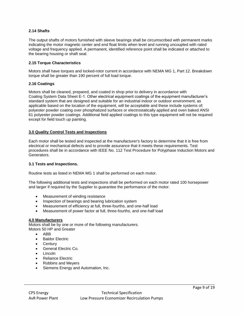
2.14 Shafts The output shafts of motors furnished with sleeve bearings shall be circumscribed with permanent marks indicating the motor magnetic center and end float limits when level and running uncoupled with rated voltage and frequency applied. A permanent, identified reference point shall be indicated or attached to the bearing housing or shaft seal. 2.15 Torque Characteristics
Motors shall have torques and locked-rotor current in accordance with NEMA MG 1, Part 12. Breakdown torque shall be greater than 190 percent of full load torque.
2.16 Coatings
Motors shall be cleaned, prepared, and coated in shop prior to delivery in accordance with Coating System Data Sheet E-1. Other electrical equipment coatings of the equipment manufacturer’s standard system that are designed and suitable for an industrial indoor or outdoor environment, as applicable based on the location of the equipment, will be acceptable and these include systems of; polyester powder coating over phosphatized surfaces or electrostatically applied and oven baked ANSI 61 polyester powder coatings. Additional field applied coatings to this type equipment will not be required except for field touch up painting.
3.0 Quality Control Tests and Inspections Each motor shall be tested and inspected at the manufacturer's factory to determine that it is free from electrical or mechanical defects and to provide assurance that it meets these requirements. Test procedures shall be in accordance with IEEE No. 112 Test Procedure for Polyphase Induction Motors and Generators. 3.1 Tests and Inspections. Routine tests as listed in NEMA MG 1 shall be performed on each motor. The following additional tests and inspections shall be performed on each motor rated 100 horsepower and larger if required by the Supplier to guarantee the performance of the motor.
Measurement of winding resistance
Inspection of bearings and bearing lubrication system
Measurement of efficiency at full, three-fourths, and one-half load
Measurement of power factor at full, three-fourths, and one-half load
4.0 Manufacturers Motors shall be by one or more of the following manufacturers. Motors 50 HP and Greater
ABB
Baldor Electric
Century
General Electric Co.
Lincoln
Reliance Electric
Robbins and Meyers
Siemens Energy and Automation, Inc.

Page 10 of 19 CPS Energy Technical Specification AvR Power Plant Low Pressure Economizer Recirculation Pumps
Pump Specification Sheet
General
Pump name LP Economizer Recirculation Pump
Pump identification number(s) 4FWC-P-101A, 4FWC-P-101B, 4FWC-P-201A, 4FWC-P-201B
Number of pumps to be furnished 4
Type designation Frame mounted end suction
Pump location Outdoors
Performance Requirements
Rated capacity, gpm 265
Rated total head (net head rise across pump), ft H2O
170
Pumped fluid Condensate
Specific gravity at rated conditions (referenced to water at 60° F)
0.926
Viscosity @ 70° F, lb/(ft-s) 0.000569
Temperatures, °F
Maximum 315
Minimum 250
Rated 290
pH range 8.5– 9
Rated net positive suction head (NPSH) available, ft H2O (absolute)
94
Maximum shutoff head, percent of rated total head
125
Maximum rotative speed, rpm 3600
Total suction pressure, ft H2O 145, Positive
Suction pressure range, ft H2O 140 - 230

Page 11 of 19 CPS Energy Technical Specification AvR Power Plant Low Pressure Economizer Recirculation Pumps
Additional Requirements
Parallel operation capability required Yes
Shop performance tests required (1 pump) Yes
Submittal of test results from previous shop tests of similar pumps acceptable (with appropriate supporting data)
No
Self-priming service No
Construction Requirements
Casing, including suction connection
Design pressure, psig
Design temperature, °F
330
Test pressure, psig 1.5 times design pressure
Impeller type Supplier’s choice
Number of stages 1
Removable shaft sleeves required Yes
Bearing type Oil Lubricated Sleeve
For centerline mounted vertical split case type pumps, the location of suction connection
N/A
Pump shall be capable of passing 1/4 inch size particle without damage to pump.
Mechanical Shaft Seals
Type Cartridge multiple spring balanced pusher
Provide seal flushing system with
Seal water heat exchanger No
Cyclone separator No
Source of flushing water Pump discharge
Pressure, psig Pump discharge pressure
Temperature, °F Pump discharge temperature
Seal flushing plan arrangement: API 682 plan number
11

Page 12 of 19 CPS Energy Technical Specification AvR Power Plant Low Pressure Economizer Recirculation Pumps
Materials
Casing Ductile iron ; ASTM A395 Grade 60-40-18 or ASTM A536 Grade 60-45-12
Impeller Carbon Steel; ASTM A216 Grade WCB
Shaft Carbon Steel; ASTM A321 Grade 1045 or ASTM A322 GR 4140 or ASTM A576, Grade 1045 or ASTM AISI 4140
Shaft sleeves 300 Stainless steel; ASTM A276 Type 316 or ASTM AISI 316
Impeller wearing rings
N/A
Casing wearing rings
N/A
Copper free construction of wetted parts required
Yes
Optional Equipment Furnished by Supplier
Bearing temperature detectors No
Vibration transducer mounting pads No
Minimum flow orifice Yes, 2in 150 class flange
Warming orifice No
Air and vacuum vent No
Additional Requirements
Pump shall be capable of accommodating a 10% increase in impeller size without changing the pump casing or shaft.
Page 13 of 19 CPS Energy Technical Specification AvR Power Plant Low Pressure Economizer Recirculation Pumps

Page 14 of 19 CPS Energy Technical Specification AvR Power Plant Low Pressure Economizer Recirculation Pumps

Page 15 of 19 CPS Energy Technical Specification AvR Power Plant Low Pressure Economizer Recirculation Pumps
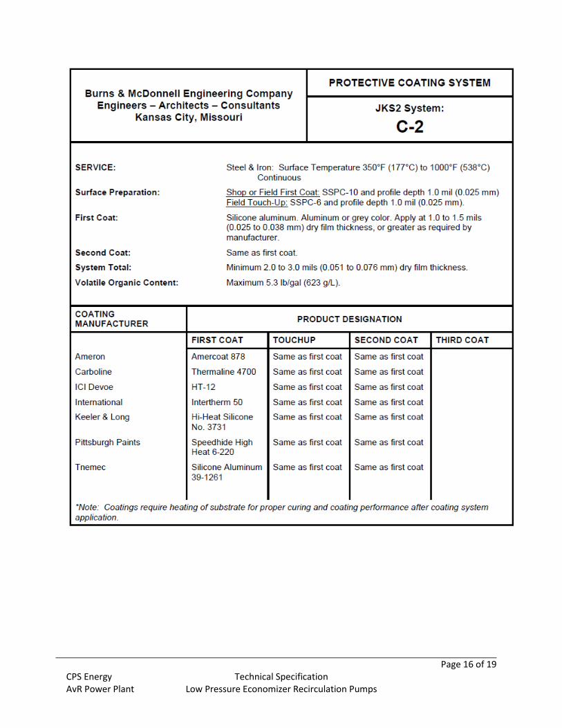
Page 16 of 19 CPS Energy Technical Specification AvR Power Plant Low Pressure Economizer Recirculation Pumps

Page 17 of 19 CPS Energy Technical Specification AvR Power Plant Low Pressure Economizer Recirculation Pumps

Page 18 of 19 CPS Energy Technical Specification AvR Power Plant Low Pressure Economizer Recirculation Pumps

Page 19 of 19 CPS Energy Technical Specification AvR Power Plant Low Pressure Economizer Recirculation Pumps