Embed Size (px)
Citation preview

NTPC DADRI (2X490MW) FGD PROJECT
TECHNICAL SPECIFICATION FOR EOWRH
NTPC DADRI 2X490 MW
FLUE GAS DESULFURIZATION SYSTEM
TECHNICAL SPECIFICATION:
ELECTRICALLY OPERATED WIRE ROPE HOIST (E0WRH)
WITH MOTOR DRIVEN TROLLEY & ALL ACCESSORIES
AND WITH MONORAIL I BEAM NPB 600 OR ISMB 600
FOR HOIST.
CUSTOMER: NATIONAL THERMAL POWER CORPORATION LIMITED
Ref: DAR: EOH: 004: REV 00
Prepared Checked Approved
litki0. rNvvrws \kA-c9--- /5 . Akv, Zi...4044.-
JYOTISH KUMAR
PATEL
SE - FGD
SHANMUG
SUNDARAM S
DM - FGD
V KES , VAN
DGM - FGD
ROO dated 28-07-2021
Page 1 of 17
NTPC DADRI (2X490MW) FGD PROJECT
TECHNICAL SPECIFICATION FOR EOWRH
Page 2 of 17
CONTENTS
1.0 INTENT OF SPECIFICATION
2.0 SCOPE
3.0 CODES AND STANDARDS
4.0 DESIGN REQUIREMENT
5.0 FEATURES OF CONSTRUCTION (MECHANICAL SYSTEM)
6.0 ELECTRICAL SYSTEM
7.0 EARTHING
8.0 MAKE OF COMPONENTS
9.0 PAINTING PROCEDURE
10.0 WARRANTY
11.0 STARTUP & COMMISSIONING SPARES
12.0 ERECTION,TESTING AND COMMISSIONING
13.0 DOCUMENTS DURING BID STAGE
14.0 DOCUMENTS ON PLACEMENT OF ORDER
15.0 INSPECTION
16.0 O&M MANUAL
17.0 PACKING
18.0 NAME PLATE

NTPC DADRI (2X490MW) FGD PROJECT
TECHNICAL SPECIFICATION FOR EOWRH
Page 3 of 17
1.0.0 INTENT OF SPECIFICATION
This specification covers design, manufacture, inspection, testing at bidder's and/ or his sub vendor’s work(s), packing, and transportation of HOIST along with accessories and Monorail I beam for Hoist etc. which is to be furnished in the Flue Gas Desulphurization plant.
a. It is not the intent to specify herein all the details of design and manufacture. However, the
equipment shall conform in all respects to high standards of design, engineering and workmanship and shall be capable of performing the required duties in a manner acceptable to Purchaser/ Customer, who will interpret the meaning of drawings and specifications and shall be entitled to reject any work or material, which in his judgment is not in full accordance herewith.
b. The requirement(s) specified under different sections of this specification shall be considered while quoting for this tender. In case of variance between sections, the requirement of CUSTOMER TECHNICAL SPECIFICATION shall prevail. NTPC DADRI contract specification provided as Annexure III to the specification & shall be referred strictly.
c. The bidder shall be deemed to have understood completely all the tender drawings and documents and quoted accordingly.
d. The bidder has to note carefully the parameters, estimated capacities of equipment indicated and the tender drawing in the specification are only for guidance of the bidder. The system shall be designed as per relevant standards/ codes and exact capacities and quantities are to be estimated by the bidder. All such estimations and design calculations shall be submitted for Purchaser’s approval.
e. Contract shall be unit rate basis for this package. Variations in quantities during contract stage shall be settled on basis of unit rate quoted by the bidder in the tender. During contract stage, quantities of various items of BOQ may vary to any extent and same unit rates will be applicable.
f. Deviation: There shall preferably be no deviation on technical specification. In case of any deviation, the bidder shall indicate separately the deviations clause-wise with respect to the specification in the ‘Schedule of Deviation’ given in Annexure-I. Deviations in any other form including clarifications / assumptions / etc will not be considered and it will be construed that the bid conforms strictly to the specification.
g. Compliance to this specification shall not relieve the Bidder of the responsibility of furnishing equipment and accessories/auxiliaries of proper design, materials and workmanship to meet the specified start up and operating conditions.
h. All accessories, items of work, though not indicated but required to make the system complete for its safe, efficient, reliable and trouble free operation and maintenance shall also be in supplier’s scope unless specifically excluded.

NTPC DADRI (2X490MW) FGD PROJECT
TECHNICAL SPECIFICATION FOR EOWRH
Page 4 of 17
2.0.0 SCOPE: This specification covers the design, material constructional features, manufacture, testing, inspection, packing and supply of electrically operated hoists assembly, with cross travel complete in all respect including control box, flexible trailing cable, cable trolleys, drag chain, auxilliary girder, FUSE-SWITCH unit, Monorail I beam for Hoist etc. The assembly shall be complete in all respect ready for erection & commissioning.
2.1.0 APPLICATION The electrical hoist and trolley is meant for handling Vacuum belt filter. 2.2.0 HOIST & MONORAIL I BEAM DATA: S.N Capacity
(Tonnes)
Quantity
(number)
Speed of the hoist
(meter per minute)
Speed of cross travel
(meter per minute)
Height (Floor to Bottom of Beam)
(m)
Head Room
(mm)
Length of cross travel
(m)
Radius of travel in
(m)
Monorail I beam for Hoist & Length
(ISMB/NPB & meter)
1 10 1 6 meter/min. (Maximum)
15 meter/min. (Maximum)
20 Vendor to Specify
10 NA NPB 600 or ISMB 600, Length 10 meter. (shall be part of Supply of Hoist Manufacturer)
S. No Description Unit EOWRH capacity, Height of Lift,
Length of travel, As Per Spec.
1
EOWRHH assembly for lifting & cross travel including brakes, drum with ropes suitable for required height of lift, electrical control panel, Pendant PB with control cable with link chain suitable against each crane capacity, Height (H), Length of travel (L)
ST To suit
2 Fuse with enclosure suitable for outdoor installation, wall mounted Per Crane
NO 1
3 Trailing flexible copper cable for power supply MR To suit
4 Galvanized link drag chain MR To suit 5 Cable trolley assembly ST To suit 6 Auxiliary girder assembly for trailing
cable for a cross travel length MR To suit
7 Rain hood for Hoist motor, cross travel motor and control box per Hoist
ST 1
8 Grease gun with grease NO 1 9 10% Lubricant ST 1 10 Monorail I beam for Hoist MR To suit
NTPC DADRI (2X490MW) FGD PROJECT
TECHNICAL SPECIFICATION FOR EOWRH
Page 5 of 17
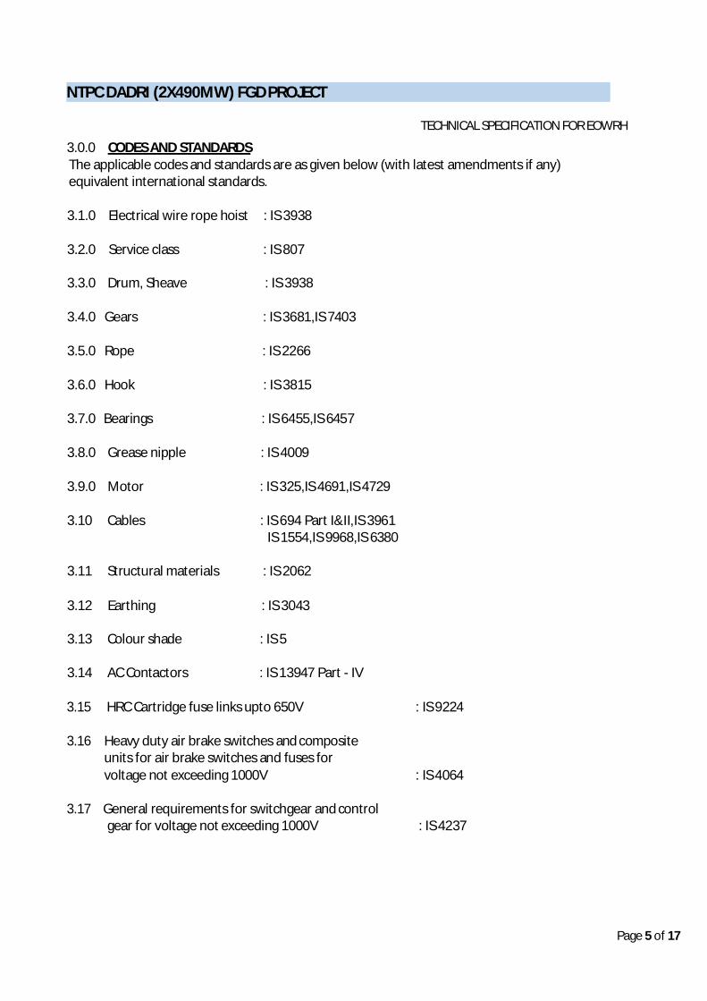
3.0.0 CODES AND STANDARDS The applicable codes and standards are as given below (with latest amendments if any) equivalent international standards.
3.1.0 Electrical wire rope hoist : IS 3938
3.2.0 Service class : IS 807
3.3.0 Drum, Sheave : IS 3938
3.4.0 Gears : IS 3681,IS 7403
3.5.0 Rope : IS 2266
3.6.0 Hook : IS 3815
3.7.0 Bearings : IS 6455,IS 6457
3.8.0 Grease nipple : IS 4009
3.9.0 Motor : IS 325,IS 4691,IS 4729
3.10 Cables : IS 694 Part I&II,IS 3961 IS 1554,IS 9968,IS 6380
3.11 Structural materials : IS 2062
3.12 Earthing : IS 3043
3.13 Colour shade : IS 5
3.14 AC Contactors : IS 13947 Part - IV
3.15 HRC Cartridge fuse links upto 650V : IS 9224
3.16 Heavy duty air brake switches and composite units for air brake switches and fuses for voltage not exceeding 1000V : IS 4064
3.17 General requirements for switchgear and control
gear for voltage not exceeding 1000V : IS 4237

NTPC DADRI (2X490MW) FGD PROJECT
TECHNICAL SPECIFICATION FOR EOWRH
Page 6 of 17
3.18 Control switches for voltage upto and including 1000 V AC, 1200 V DC : IS 6875 (Part-I&II)
3.19 The offered Hoist shall comply with all the latest statuary regulation and safety
code/standard applicable. Nothing in this specification shall relieve the vendor of his responsibility.
4.0.0 DESIGN REQUIREMENT
Electrical hoists and trolley shall be complete with hoisting and cross travel motor, wire rope drum, wire rope, hook, gear box for CTs hoist wheels with Trolley necessary gearing, sheaves, Brake Electro mechanical type with asbestos lining for hoisting & cross travel, guides, weather and dust proof pendent push button station, & control panel, all wiring, 4 core trailing cable for power supply connection galvanised drag (link) chain with complete supporting arrangement, pendent cable, limit switches, earthing terminals and other accessories to make system complete and ready for erection & commissioning. The hoist assembly shall be fully balanced. Counter weight, if any, required shall be supplied as a part of the system. Limit switches shall be provided for over hoisting, over lowering and for cross travel limits at both extreme position. The supplier shall provide 63A fuse switch unit (FSU) with enclosure designed for IP 55 degree of protection, to receive the power supply. The FSU shall be provided with crimping type ATC lug to receive owner's Aluminium unarmoured power cable. The FSU shall be located 5meters away from the hoist. Control supply shall be 110V AC, 50Hz and the same shall be derived from 3ph, 415V, and 50Hz supply provided at 63A FSU. Suitable earthing terminal shall be provided in the FSU enclosure for terminating the earth conductor of the flexible trailing cable. All outdoor Electrical equipments shall be suitable for IP 55 Degree of protection.
5.0.0 FEATURES OF CONSTRUCTION (MECHANICAL SYSTEM)
5.1.0 DRUM Rope drum shall be either cast/seamless/welded to sustain concentrated loads resulting from the rope pull. Drum shall be machine grooved right or left or both with grooves of a proper shape to suit the ropes used.
Drum shall accommodate all the length of the rope required for the lift plus two dead wraps at each anchor point, without over lapping. The hoist mechanism shall consist of a grooved rope drum driven by electric motor through gears. Each end of the rope shall be anchored to the drum in such a way as the anchorage is readily available for maintenance. Each rope shall have two (2) full turns of the drum when the hook is at its lowest position and one (1) spare groove when the hook is at its highest position. The leading rope taken by the drum should not slope sideways when slack and it should not be caught between the gear wheel.
5.2.0 SHEAVES
Rope sheaves shall be of rolled or cast steel. Grooves shall be machined to the proper shape

NTPC DADRI (2X490MW) FGD PROJECT
TECHNICAL SPECIFICATION FOR EOWRH
Page 7 of 17
for the rope used. Sheaves shall be equipped with sheave guards to retain the rope in groove. Sheaves shall be fully guarded so that the rope cannot come off.
5.3.0 GEARS
Gears shall be cut from quality alloy steel of chromium, nickel. Pinions shall be of heat treated alloy steel.
5.4.0 BEARINGS
Bearings shall comply with relevant IS/BS. Depending upon the capacity and loading conditions the manufacturer shall design suitable grease lubricated or oil lubricated bearings.
5.5.0 ROTATING AND STATIONERY SHAFT
Shafts and axles shall be of 080 M40 as per BS 970
5.6.0 LUBRICATION The hoists shall be supplied with all required lubricants, one number grease gun shall be supplied.
5.7.0 HOIST ROPE
Hoist ropes shall be of Pre-formed type, hemp cored, regular lay 6/36 construction with a breaking strength of 160 -175 kgf/ sq. mm.The rope shall be of sufficient length so that two full wraps shall remain on the drum at the extreme low position of the hook.Number of falls shall be FOUR. Braking loads for the hoist rope shall not be less than six times the calculated load in the ropes at the drum, based on rated load on hook plus the weight of the bottom block plus the weight of the rope. Hoisting rope shall confirm to IS 2266.The rope shall be hot dip galvanised. The rope shall be free from kinks and shall be continuous.
5.8.0 HOOK
Hooks made of EN-8 material shall be solid, forged, heat treated, high tensile steel of tough construction and shall be provided with a standard depress type safety latch. It shall have swivels and operate on bearings with hardened race. Lock to prevent hooks from unscrewing shall be provided.
5.9.0 BRAKES
Hoisting motor and trolley motor shall be equipped with Electro Mechanical type with asbestos lining. The brakes shall apply when either the motor starter or the main power switch is in OFF position or in the event of "power failure". The braking capacity of the brakes shall be 150% of the rating of the hoist.
5.10.0 ROPE GUIDE
Rope guides shall have wear resistant property, prevents slack rope, and retains wire rope in the barrel grooves.
5.11.0 LINK (DRAG) CHAIN
Hot dip Galvanised Link (drag) chain shall be provided for the Flexible Trailing cable, to avoid direct loading on the cable.

NTPC DADRI (2X490MW) FGD PROJECT
TECHNICAL SPECIFICATION FOR EOWRH
Page 8 of 17
5.12.0 AUXILIARY GIRDER FOR TRAILING CABLE
Auxiliary girder system shall be provided for the support of Flexible Trailing cable. The Trolleys for the trailing cable shall be supported by the Auxiliary Girder. The Auxiliary Girder will be supported by the main beam (main beam will be supplied by the Purchaser). The hoist supplier shall provide obligatory support materials to support the Auxiliary Girder on the main beam at an interval not exceeding 750mm. complete structural materials required for Auxiliary Girder system shall be included in the scope of supply of the hoist supplier.
5.13. 0 MONORAIL BEAM FOR HOIST The Monorail Beam for Hoist shall be part of supply of Hoist Manufacturer. The supply of Monorail beam shall be in a Single pieces for required Length (10 meter).
6.0.0 ELECTRICAL SYSTEM Electrical system comprises of 63A Fuse Switch Unit, Control panel, Pendent Push Button Station, Trailing cable, Pendent cable, Hoist & Cross travel motors with electro mechanical brake etc., to make the system complete.
6.1.0 CONTROL PANEL
6.1.1 Control panel shall be provided to house the electrical components like fuses, contactors, over
load relays, isolators, switches, control supply transformers etc along with necessary wiring. The components shall be clearly identified by labels. The panel shall be made of sheet steel of minimum 2mm thick CRCA sheet steel and shall be dust and vermin proof, suitable for outdoor condition. The control panel shall be designed for IP 55 degree of protection. Adequate number of DOUBLE COMPRESSION type cable glands (heavy duty) of brass with nickel plating and Annealed Tinned Copper lugs shall be provided with dummy plugs. The door, removable cover plates and metal- to-metal joints shall be fully neoprene gasketted.
6.1.2 The control panel shall be pre treated in seven tank process and epoxy painted.
The paint colour will be informed during drawing approval.
6.1.3 Dry type step down control supply transformer 415V/110V AC shall be provided to derive control supply for starter operation and indication. The transformer shall have minimum class ‘B’ insulation. The rating of the transformer shall be decided based on maximum power consumption plus 25% margin. The transformer shall meet IS 12021
6.2.0 MOTOR
The motor shall meet IS 325 or equivalent international standards. The motor shall be designed for frequent reversal, braking and acceleration. Frequency of reversal shall be minimum 125 times/hour. The motor shall be rated for S4 duty 40% cyclic duration factor. Maximum continuous rating shall have at least 10% margin over maximum load demand including voltage and frequency variations, temperature rise and other variations. The body shall have two earthing points on opposite sides.

NTPC DADRI (2X490MW) FGD PROJECT
TECHNICAL SPECIFICATION FOR EOWRH
Page 9 of 17
6.2.1 ENCLOSURE The motor shall be provided with an enclosure fully meeting the requirements of IP 55 as per IS 4691 meant for outdoor service. In addition rain-hood shall be provided for the motors. The motor shall be Totally Enclosed Fan Cooled (TEFC) type.
6.2.2 INSULATION AND WINDING
Motors shall have minimum class "B" type insulation. The winding shall be suitable for successful operation in hot, humid, & tropical climate with the ambient temperature of 50 degree centigrade. The temperature rise shall be limited to 70 degree C (by resistance method) over an ambient of 50 degree C. The insulation shall be given fungicidal and tropical treatment as per IS 3202.
6.2.3 MOTOR FRAME
The frame shall be cast and rigid.
6.2.4 DIRECTION OF ROTATION
The motors shall be designed for both directions of rotation.
6.2.5 TERMINAL BOX OF MOTORS The terminal box shall be weather and water tight and suitable for outdoor service, having a degree of protection of IP 55.It shall be provided with removable front cover for making connections. Neoprene gaskets at cover joints shall be provided. The terminal box shall be suitable to withstand 31 MVA for 0.25 seconds without damaging the box with fuse protection. Nickel-plated brass double compression cables glands and ATC lugs shall be provided to receive the power cables.
6.2.6 VIBRATION
The motor vibration and noise shall be within the limits specified in IS 12065 and IS 12075. The noise level shall be limited to 85 dB when measured at a distance of 1.5m from the Hoist assembly.
6.3.0. SWITCHES
Heavy-duty power switches with quick make and brake mechanism meeting relevant IS requirements shall be provided. The switches shall be adequately rated to get complete protection even under abnormal operating conditions.
6.4.0. CONTACTOR 6.4.1 All Contactors shall be suitable for DOL application of full voltage with coils suitable
for the control voltage provided by the supplier. Contactor construction shall be rugged and such as to avoid ingress.
6.4.2 For control purpose, only Auxiliary contactors shall be used. Relays are not acceptable in place of Auxiliary Contactors.
6.4.3 The power contactors shall heave Mechanical interlocking in addition to Electrical
interlocking so that at any point of time only any one of the two Power contactors (either Up of Down, Left or Right) will be energized.

NTPC DADRI (2X490MW) FGD PROJECT
TECHNICAL SPECIFICATION FOR EOWRH
Page 10 of 17
6.5.0 THERMAL OVER LOAD RELAYS Thermal over load relays wherever provided shall be ambient temperature compensated with suitable setting ranges. The relay shall be provided with a door mounted hand reset push button. The O/L relay shall have inbuilt single phasing protection as built-in feature.
6.6.0 FUSES 6.7.0 Only HRC fuses of plug-in type with Class-4 AC duty shall be provided. 6.7.1 Fuse base shall be rugged. Adequate shrouding shall be provided for live accessible parts and it
shall be possible to replace any fuse without damages of contacts when the circuit is alive.
6.7.0 INDICATING LAMPS
LED type indicating lamps of low watt consumption with suitable built-in series resistor shall be used. LED and lenses shall be inter-changeable and easily replace- able from the front. The indication lamps shall be properly shrouded so as to prevent the dust and water entry. Indicating lamp shall be provided for “Hoist motor ON”,”CT motor ON”, ”Hoist motor TRIP”, ” CT motor TRIP”, “Supply ON” etc.,
6.8.0 WIRING
The control panel wiring shall be complete in all respects and ready for connection of external power for terminating external cables. Necessary cable glands alongwith suitable terminal blocks and lugs to receive trailing cable and pendent push button cable shall be provided. The cable glands, lugs and terminal blocks shall not be supplied loose. Point to point wiring shall be adopted. Not more than two wires shall be terminated at each terminal. Wiring shall be neatly laid out and bunched together suitably. The wiring shall be done with min. 2.5 sq.mm multistranded copper, PVC insulated 650V/1100V wires.
6.8.0 TERMINATION 6.8.1 All power and control wires shall be terminated on terminal block/component using
crimping type tinned copper lugs/connectors.
6.8.2 Terminal block shall be used for control wiring. The terminal blocks shall be complete with insulated barriers, terminal studs, washers, nuts, lock nuts and identification strips with terminal numbering.
6.9.0 PENDANT PUSH BUTTON STATION 6.9.1 The Pendant Push Button station shall have the following Push Buttons.
Hoist, Lower, Forward, Reverse & Emergency Stop. The Emergency Pus Button shall be Lockable type.
6.9.2 The Pendant Push Button station shall have the following LED type Indicating lamps. SUPPLY
ON, HOIST MOTOR ON, CT MOTOR ON, HOIST MOTOR TRIP, CT MOTOR TRIP.
6.9.3 The Pendant Push Button station shall be supported from the Control Panel with hot dip galvanized Link Chain.

NTPC DADRI (2X490MW) FGD PROJECT
TECHNICAL SPECIFICATION FOR EOWRH
Page 11 of 17
6.9.4 The Pendant Push Button Station shall be connected to the Control Panel using multi-core
copper flexible control cable of 10m length. 6.9.5 The Enclosure of Pendant Push button station shall be designed for IP 55 degree of protection. 6.9.6 Push button shall be spring return type with 2NO+2NC self reset contacts rated for 5A at
415 volts AC. The push buttons for different operations like “HOIST / LOWER, FORWARD/ REVERSE”, “STOP” shall have different colours. All push buttons shall be as per relevant IS.
6.9.7 The Push button shall be properly shrouded so as to prevent water & dust entry.
6.10.0 LIMIT SWITCHES:
6.10.1 Limit switches shall be provided for over hoisting, over lowering, Extreme left and Extreme
right positions. 6.10.2 Necessary Limit switch actuating arrangement shall be provided to actuate the limit switch at
the above positions.
6.10.3 The Limit switches shall have enclosures designed for IP 55 degree of protection. 6.10.4 Proximity switches are not acceptable in place of Limit switches.
6.11.0 FUSE SWITCH UNIT
Metal enclosed, FOUR POLE fuse switch unit of 63A, 415V, AC, rating suitable for indoor location shall be provided. Suitable Nickel-Chromium plated brass DOUBLE COMPRESSION glands and crimp type ATC lugs to receive purchaser's 3c-6 sq. mm AL unarmoured FRLS cable & vendor’s 4C-4 sqmm copper unarmoured cable shall be provided. Cable glands and lugs shall also be provided for the flexible trailing cable. The FSU shall be provided with 2 Nos of earthing terminals with M12 screws, nuts and washers.
6.11.0 CABLES 6.11.1 The trailing cable shall be 1100 V grade extra flexible having 4 cores and as per IS 9968. The
trailing flexible cable shall carry the power supply to the Hoist from the Switch Fuse unit. The conductor cross section shall be minimum 4 sq.mm multi- stranded tinned copper of class 5 of IS 8130. the insulation shall be heat resistant elastomeric compound based on ETHYLENE PROPYLENE RUBBER (EPR) with continuous withstanding temperature of 90 Deg C The inner sheath shall be heat resistant elastomeric compound with black colour. The outer sheath shall be marked with cable size, voltage grade by embossing , sequential marking at every one meter of length by embossing .
6.11.2 The power cables between HOIST / CT MOTORS to control box, the pendent cable and other
control cables shall be as per IS 1554. The conductor shall be multi- stranded PLAIN ANNEALED copper with minimum cross section of 1.5 sqmm for control. The insulation shall be extruded PVC. The inner sheath shall be extruded PVC and the outer sheath shall be extruded-PVC. In addition, the outer sheath shall be marked with cable size, voltage grade, the word FRLS at every 5 meters and sequential marking of length at every one meter. The sheath shall be black in colour.

NTPC DADRI (2X490MW) FGD PROJECT
TECHNICAL SPECIFICATION FOR EOWRH
Page 12 of 17
7.0.0 EARTHING
The structure, motor frames and enclosures of electrical equipment shall be effectively connected to earth complying with Indian Electricity rules and IS 3043. The earthing materials from hoist to FSU shall be in supplier’s scope. BHEL will provide the earthing material from the Switch Fuse Unit to the nearest Earth Grid. Any other Items/components other than specified above , which are required for proper functioning of the Hoist are also part of the vendor Scope of Supply.
8.0.0 MAKE OF COMPONENTS: Only one of the following makes shall be used. Mix up of make for same item is not acceptable. Any deviation with respect to the makes given below is not acceptable.
Sl No. Components Make 1. Hoist/Cross travel motor AUTOLEC/SIEMENS/KEC/NGEF/ABB/CROMPTON
GREAVES/BHARATBIJLEE/GEC 2. Cable INCAB/CCI/DELTON/FORT GLOS-TER/ UNIVERSAL CABLES/
ASIAN CABLES /NICCO/ IACL/IN-DUSTRIAL CABLES/KEI 3. Fuse switch unit L&T/ SIEMENS 4. Power switch L&T/ SIEMENS 5. Power contactor L&T/SIEMENS/TELEMEC-HANIQUE / BCH 6. Auxiliary contactor L&T/SIEMENS/TELEMECHNIQUE/BCH 7. Thermal overload relay L&T/SIEMENS/TELEMECHNIQUE/BCH 8. Fuse L&T/ SIEMENS 9. Push button L&T/SIEMENS/BCH/TEKNIC/VAISHNO 10. LED type Indicating lamp L&T/SIEMENS/BCH/TEKNIC/BINAY/VAISHNO 11. Internal wiring BIS (IS) CERTIFIED MAKE 12. Glands COMET/SUNIL & CO /QUALITY PRECISION / ARUP ENGG. 13. Lugs DOWELS 14. Terminal block ELMEX/TOSHA/CONNECTWELL 15. Control switch L&T/ SIEMENS/KAYCEE 16. Selector switch L&T/ SIEMENS/KAYCEE
17. Fuse carriers L&T/ SIEMENS
18. Auxiliary transformer AE/KAPPA/IND COIL/LOGIC STAT/PACTIC / PRAGATI / PRAYOG/VIKAS/KANIVEY/GPDL
19. Neutral link L&T/ SIEMENS
20. Hoist Brake L&T/ SIEMENS
21. Cross Travel Brake EMCO/PRETHE
22. WIRE ROPE USHA MARTIN
23. Limit Switch BCH/JAI BALAJI/SIEMENS/KAYCEE
24. Bearings SKF/FAG/NORMA
Note: Make of various components are subject to NTPC approval. No additional delivery or price implication is acceptable due to NTPC comment on make of components. Mix up of make for same item is not acceptable in any enquiry.

NTPC DADRI (2X490MW) FGD PROJECT
TECHNICAL SPECIFICATION FOR EOWRH
Page 13 of 17
9.0.0 PAINTING PROCEDURE: For Painting of Hoist & Monorail I Beam Refer Annexure-II.
10.0.0 WARRANTY: The warranty period shall be twenty four (24) months from the date of Supply or eighteen (18) months from the date of commissioning, whichever earlier.
11.0.0 START UP & COMMISSIONING SPARES: Start-up & Commissioning Spares shall be part of the main supply of the EOWRH. Start-up & commissioning spares are those spares, which may be required during the start- up, and commissioning of the equipment/system. Bidder shall provide an adequate stock of such start up and commissioning spares to be send the site for the equipment erection and commissioning along with main supply. The spares must be available at site for the equipment’s are energized.
12.0.0 ERECTION & COMMISSIONING
Erection & Commissioning of EOWRH with accessory & Monorail I Beam for Hoist will be done by owner as per vendor’s Erection & commissioning Manual and check List for EOWRH.
13.0.0 DOCUMENTS TO BE SUBMITTED DURING BID STAGE
(A) Along with the offer i) Quality plan, General arrangement drawings, DSL & interlock mechanisms
(female & male) arrangement drawings with complete bill of materials. All despatch able components/assemblies shall be indicated in details. Sub- vendors items, make also shall be indicate in the drawings.
ii) Wiring circuit diagram with details of make type and rating of all the components.
iii) Spares list for 3 years of trouble free operation along with the prices .commissioning /Initial spares shall form part of the base offer.
iv) Write up on special feature if any. v) Technical specification of the equipment. vi) Catalogues and other details of the product shall be submitted along with
the offer. vii) Clause by clause conformation for this TEP viii) Rating of cross travel and hoist motor ix) Deviation, if any to be spelt out clearly. Any clarification furnished against
any clause of the TEP will be constructed as compliance only. x) BOM for the system

NTPC DADRI (2X490MW) FGD PROJECT
TECHNICAL SPECIFICATION FOR EOWRH
Page 14 of 17
14.0.0 DOCUMENTS TO BE FURNISHED ON PLACEMENT OF ORDER:
Immediately on placement of order, the supplier shall submit the following Documents to BHEL for approval. Manufacturing shall be initiated only after obtaining approval from BHEL.
a. General Arrangement drawing of Hoist, Cross Travel arrangement, Auxiliary
Girder & Trailing cable system, Control Panel, Pendant Push button station, Monorail I Beam etc.
b. Bill of materials for the Hoist, Cross travel arrangement, Auxiliary Girder
System, all cables under the scope etc.
c. Power and Control scheme.
d. Bill of material indicating description of the item, rating, make, quantity, type reference etc., for a) Panel mounted components, b) Pendent mounted components, c) Items covered in the system like trailing cable, trolley etc.,the make of components shall be separate and form part of vendor QP.
e. Hoist & Monorail I beam mounting arrangement.
f. Gasketting and locking arrangement of Control panel.
g. Justification for a) Motor rating selected, b) Rope selected, c) VA rating of control transformer.
h. List of items mounted in the assembly and list of loose item supplied along with
weight. i. Packing drawings.
j. Data sheet for Hoist, Data sheet for Hoist & cross travel motor, Data sheet for
Brake and Data sheet for trailing & pendent cable.
k. Cable schedule for hoist indicating size, termination between which equipment, Rating, quantity, make etc.
l. Shipping list indicating items, quantity, weight and package number to be
submitted before inspection call is given. Despatch shall be maintained in line With the shipping list.
m. All the drawings shall be prepared in AutoCAD. After final approval the above
documents shall be submitted in CD apart from hard copy.
n. The drawings and data sheets shall be submitted in soft media.pdf format, apart from 6 sets from hard copy. For BHEL approval.

NTPC DADRI (2X490MW) FGD PROJECT
TECHNICAL SPECIFICATION FOR EOWRH
Page 15 of 17
15.0.0 INSEPCTION: The inspection will be carried out based on the following documents.
1. BHEL Purchase order 2. BHEL Technical specification 3. Quality plan, Quality checklist indicated in the Enquiry. 4. BHEL approved supplier drawing/data sheets.
16.0.0 O&M MANUAL: 16.1.0 5 copies O&M instruction manual shall be supplied. Instruction manual shall be
submitted in SOFT MEDIA apart from the hard copies. Immediately after the despatch of the Hoist, directly to BHEL Ranipet. The O&M manual shall also be submitted in CD apart from hard copies.
16.2.0 Draft O&M manual shall be submitted on obtaining approval of various manufacturing drawings / documents for BHEL review & approval.
16.3.0 The O&M manual shall include but not limited to the following. a) Do’s & Don’ts during receipt, storage, erection & commissioning. b) Instruction to be followed on receipt, storage & erection. c) Construction details of the hoist assembly. d) Drawing indicating various parts of EOWRH assembly with part numbers. e) Recommended lubrication & maintenance schedule. f) Cut view drawing for the Gear box assembly. g) As Built drawings, BOM & Cable schedule.
17.0.0 PACKING: 17.1.0 The ELECTRICAL HOIST and accessories shall be properly packed so as to avoid
damage during transit and storage. 17.2.0 Wooden crate shall be used for packing various equipment / items as per shipping
list. Lining with plastic sheet shall be provided inside the crate to avoid water entry during transit / storage.
17.3.0 Packing drawing shall be submitted for BHEL approval. 17.4.0 Two sets of manual (Hard copies) with drawing & data sheet shall be sent along with
the packing box. 17.5.0 Each packing shall be accompanied with packing slip and all relevant drawings. 18.0.0 PACKING AND FORWARDING: Each package or shipping units shall be clearly marked or stenciled on at least two sides as follows.
BHEL SITE OFFICE, 2 X 490 MW, FGD PACKAGE (STAGE 2)
NCTPS – NTPC DADRI
GAUTAM BUDH NAGAR, UP – 201008. INDIA
In addition, each package or shipping unit shall have the symbol painted in red on at least two sides of the package, covering one fourth of the area of the side.

NTPC DADRI (2X490MW) FGD PROJECT
TECHNICAL SPECIFICATION FOR EOWRH
Page 16 of 17
ANNEXURE-I LIST OF DEVIATIONS/EXCEPTIONS TO THE ENQUIRY DOCUMENT
Sl No
Clause No
Page No Description of Deviation
Note: Enlarge the table to incorporate items SIGNATURE OF BIDDER -------------------- NAME ------------------- DESIGNATION ---------------------

NTPC DADRI (2X490MW) FGD PROJECT
TECHNICAL SPECIFICATION FOR EOWRH
Page 17 of 17
Bidders Acceptance/ Comments
ANNEXURE-II Painting of Hoist & Monorail I Beam
Refer Enclosed specification.
ANNEXURE-III Customer Technical specification
Refer Enclosed specification.
ANNEXURE-IV General Layout of Hoist
Refer Enclosed specification.
SIGNATURE OF BIDDER -------------------- NAME ------------------- DESIGNATION ---------------------

PS- NCTPP DADRI II 4X490 MW FGD PACKAGE REV. 03 DATE 09.06.2018 Page 18 of 33
loss
loss

PS- NCTPP DADRI II 4X490 MW FGD PACKAGE REV. 03 DATE 09.06.2018 Page 17 of 33
loss
loss

CLAUSE NO.
TECHNICAL REQUIREMENTS
NCTPP DADRI ST-II (2X490 MW) & IGSTPP
JHAJJAR(3X500 MW) FLUE GAS DESULPHURISATION (FGD)
SYSTEM PACKAGE
TECHNICAL SPECIFICATION SECTION-VI, PART-B
BID DOC.NO. CS-6130/0330-109-9
SUB-SECTION-I-M6 LIMESTONE AND
GYPSUM HANDLING PLANT(LHP & GHP)
Page 6 of 74
4.1.8 Belt Vulcanizing Machine
Belt Vulcanizing Equipment shall be suitable for hot vulcanizing of belt splice and shall be of easy-to-handle type. Equipment should be suitable for vulcanizing of entire splice width in single setting. Equipment should be capable of applying uniform pressure over the splice by pneumatic or hydraulic means. Heating element should be preferably of flexible type.
4.2.0 ELECTRO HYDRAULIC THRUSTER BRAKES
The necessary Electro Hydraulic Thruster (AC) brakes / disc brakes, totally enclosed and fail safe, shall be provided as required for various equipment’s. Braking torque shall be adjustable from 0 to 100% of rated braking torque. The thruster brake shall be actuated by compression springs. The electro hydraulic thruster shall be fitted with the brake. Limit switches shall be provided for brake applied/released positions. The windings shall be provided with class-B insulation suitable for 415V ± 10% at 50 Hz ± 5% and combined variation of ± 10%. Brake lining shall be asbestos with inter woven brass wires capable of withstanding 200°C temperature.
Clamp
Electro-hydraulic thruster rail clamp shall be actuated by compression springs, the spring shall apply the clamping force directly on the Rail clamp mechanism once power supply is cut-off. The force transmission mechanism from spring to rail clamp faces shall be very simple with minimum linkages. Manual rail clamp shall be provided with positive locking arrangement and shall apply clamping force directly on rails. The manual rail clamp shall be of proven design.
4.3.0 MONORAILS AND HOISTS
4.3.1 The Monorails & Hoists shall conform to the latest edition of the following standards & codes. Other internationally acceptable standards/codes, which ensure equal or higher performance than those specified, shall also be accepted.
IS:3938 : Specification for Electric Wire Rope Hoist
IS:3832 : Chain pulley blocks
IS:2429 : Round steel short link chain
IS:6216 : Short link chain grade 80
IS:15560 : Points hooks with shank up to 160 Tonne - Specification
IS:210 : Cast Iron Castings
4.3.2 For the Hoists with more than 2.0 tonne lifting capacity or more than 10.0 M lift, with the exception of hoists for GTU and bend pulleys motor operated hoist blocks for both long travel and lift shall be provided. Other hoist blocks shall be of hand operated type for both travel and lift. All monorails coming out of the buildings shall be provided with electric hoist blocks, irrespective of load and lift. Minimum 3 meter length of Cantilever from edge of building/cladding, shall be provided in monorails coming out of the building to lower the equipment to ground level clearing the building sidewalls / cladding and any other facilities beneath the floor upto ground level. Clear height shall be maintained when handling one equipment over other, in such case dismantling of any equipment shall not be permitted. The center line of monorail shall not deviate by more than 500 mm from the center of gravity of any equipment that is to be lifted.
ANNEXURE - II Customer Technical specificationANNEXURE - III Customer Technical specification

CLAUSE NO.
TECHNICAL REQUIREMENTS
NCTPP DADRI ST-II (2X490 MW) & IGSTPP
JHAJJAR(3X500 MW) FLUE GAS DESULPHURISATION (FGD)
SYSTEM PACKAGE
TECHNICAL SPECIFICATION SECTION-VI, PART-B
BID DOC.NO. CS-6130/0330-109-9
SUB-SECTION-I-M6 LIMESTONE AND
GYPSUM HANDLING PLANT(LHP & GHP)
Page 7 of 74
4.3.3 The electric hoist shall be designed and constructed in accordance with the latest revision of IS:3938 and shall be suitable for duty class 2. For electric hoists, trolley movement and hoisting shall be effected by using two separate motors. Motors shall be as per technical requirements discussed elsewhere. However the motors shall be suitable for 150 starts per hour at 40% CDF. Motor operated geared trolley shall have two (2) pairs of wheels, one pair of which shall be driven through motor. An electromechanical brake shall be provided for hoisting as well as cross travel. Brake lining shall be of asbestos
4.3.4 Wire rope shall be of pre-formed type, hemp cored, regular lay 6/36 construction with a breaking strength of 160 -175 kgf/ sq. mm. Minimum number of falls of rope shall be four (4). All running shafts and wheels shall be fitted with ball / roller bearings with a rated life not less than 20 years based on equivalent running time as per IS:3938.
4.3.5 All chain pulley blocks shall be designed to IS:3832, the operating hand chain shall conform to IS:2429 grade 30 pitched and polished and the load chain to IS:6216 grade 80. The chain pulley block shall be suitable for duty class 2. Hooks shall be as per IS: 15560 & with antifriction bearing.
4.3.6 The hoist mechanism shall consist of a grooved rope drum driven by electric motor through gears. Each end of the rope shall be anchored to the drum in such a way as the anchorage is readily available for maintenance. Each rope shall have two (2) full turns of the drum when the hook is at its lowest position and one (1) spare groove when the hook is at its highest position. The leading rope taken by the drum should not slope sideways when slack and it should not be caught between the gear wheel.
4.3.7 Inline magnetic separator shall have motorised hoist for handling / maintenance purpose. Each suspended magnet shall be provided with a dedicated motorised trolley.
4.4.0 CHUTES, SKIRT BOARDS, FLAP GATES, ROD GATE AND RACK & PINION GATE
4.4.1 Chutes
i. Direct impact of material on conveyor belt shall be avoided by providing an inclined surface at 60 degrees valley angle at the feeding point to guide the material in the direction of belt travel. Further, chute construction below flap gate shaft shall be such that there will not be any accumulation of limestone dust between chute and flap gate in that zone. Hoppers and Chutes shall be made of minimum 20 mm thick TISCRAL / SAILHARD / LSLAS07 or equivalent material. Long chutes guiding flow from considerable height shall be provided with impact plates wherever change in direction of flow takes place. Hinged inspection doors of leak proof construction shall be provided for access/ maintenance purpose at approachable heights for chutes and flap gates. All chutes should have one inspection door at every floor and for the ones in between the floors (more then 1.5 meter above the operating floor level) suitable access for trouble free maintenance shall be provided. For sealing of inspection doors labyrinth type arrangement to be provided. In addition to positive locking arrangement, mounting bolts, to tighten the door further against rubber shall also be provided. Bottom sides along with its adjacent sides shall be flanged and made from TISCRAL or equivalent material of 20 mm thickness. The non-striking surface i.e. the covers of the trough shall be of 10 mm thick mild steel and bolted to the flange provided on the trough. Further, the chute boxes not more than 1.5 m in length shall be joined through bolted flange connection to form the chute legs. Adequate care shall be taken to locate the flange joint away from floor level for easy maintenance. Complete chute work in the region of flap gates shall be fabricated from 20 thk TISCRAL or equivalent. In case of vertical chute (valley angle more than 80 degree) complete chute, work shall be of 20 mm thick TISCRAL or equivalent material.

CLAUSE NO.
TECHNICAL REQUIREMENTS
NCTPP DADRI ST-II (2X490 MW) & IGSTPP
JHAJJAR(3X500 MW) FLUE GAS DESULPHURISATION (FGD)
SYSTEM PACKAGE
TECHNICAL SPECIFICATION SECTION-VI, PART-B
BID DOC.NO. CS-6130/0330-109-9
SUB-SECTION-I-M6 LIMESTONE AND
GYPSUM HANDLING PLANT(LHP & GHP)
Page 35 of 74
DATA SHEET: MONORAILS AND HOISTS
1.0.0 GENERAL
1.1.0 Functional Requirement : To transfer equipment’s to maintenance area or outside the building.
2.0.0 DESIGN & CONSTRUCTION REQUIREMENT
2.1.0 Hoists
2.1.1 Drive
(i) More than 2.0 tonne or more than 10.0 m lift or hoists coming out-side the buildings
Motor driven for both travel & lift.
(ii) Other hoists including the hoists for handling takeup pulley and takeup weight
Manual for both travel & lift.
2.1.2 Maximum trolley travel speed for electric hoists
15m/min
2.1.3 Maximum Hoisting speed for electric hoists 6 m/min
2.1.4 Drive Motors SQIM, Separate for travel & lift
2.1.5 No. of starts for drive motor 150 starts/hr at 40% CDF
2.1.6 Wire Rope
(i) Type/Construction Pre-formed type, hemp cored, regular lay 6/36 construction
(ii) Breaking Strength 160-175 kgf/sq. mm
2.1.7 Bearing
(i) Type Ball/Roller bearing
(ii) Life 20 years
2.1.8 Brake Electro Mechanical type with asbestos lining.
2.1.9 Load Hook Swiveling type forged circular shank section.
2.1.10 Duty Class –2
2.2.0 Monorail location/layout
2.2.1 Cross section I beam
2.2.2 Distance between C/L of monorail & C.G. of equipment to be lifted
Maximum 500 mm

CLAUSE NO.
TECHNICAL REQUIREMENTS
NCTPP DADRI ST-II (2X490 MW) & IGSTPP
JHAJJAR(3X500 MW) FLUE GAS DESULPHURISATION (FGD)
SYSTEM PACKAGE
TECHNICAL SPECIFICATION SECTION-VI, PART-B
BID DOC.NO. CS-6130/0330-109-9
SUB-SECTION-I-M6 LIMESTONE AND
GYPSUM HANDLING PLANT(LHP & GHP)
Page 36 of 74
2.2.3 Power Cables Support Festoon type arrangement
2.3.0 Manual Hoists
2.3.1 Maximum manual effort for operation. 30 kg

6250 6250 6250 6250 7000
9250
9250
6250 6250 6250 6250 7000
32000
1850
0
6250 6250 6250 6250 7000
9250
9250
6250 6250 6250 6250 7000
32000
1850
0
6000
4000
2200
40009250 9250
32000
10000
2000
0
6250 6250 6250 70006250
*
*
* *
* *
* *
* *
* *