Embed Size (px)
Citation preview

Technical Specification
FLUXUS® F608
TSFLUXUS_F608V1-4EN_Leu, 2011-03-03 1
FLUXUS F608 supported by handle
Measurement with transducers mounted by the portable Variofix VP
Measurement with the flow transmitter fixed to the pipe by the QuickFix pipe mounting fixture
FLUXUS F608
FLUXUS F608
Portable Ultrasonic Flow Measurement of Liquids in Hazardous Areas
Portable instrument for non-invasive, quick ultrasonic flow measurement with clamp-on technology for alltypes of piping
Features
• Precise bi-directional and highly dynamic flow mea-surement with the non-intrusive clamp-on technology
• High precision at fast and slow flow rates, no tempera-ture and zero drift
• Portable, easy-to-use flow transmitter with 2 flow chan-nels, multiple inputs/outputs, an integrated data logger with a serial interface
• Extremely resistant carbon fiber housing
• Covered by ATEX zone 2 certification ( II3G), IP65 protection - No hot work permit required for hazardous areas
• Compact and very lightweight, allowing the measuring system to be easily carried as personal luggage, e.g. for offshore visits
• Water and dust-tight (IP65); resistant against oil, many liquids and dirt
• Li-Ion battery provides up to 14 hours of measurement operation
• Automatic loading of calibration data and transducer detection for a fast and easy set-up (less than 5 min), providing precise and long-term stable results
• User-friendly design
• Transducers available for a wide range of inner pipe di-ameters ( ) and fluid temperatures ( )
• Rugged transducers (ATEX-Zone 1 und 2, resistant to rough environments, dust and humidity)
• Robust, water-tight (IP67) transport case with compre-hensive accessories
• HybridTrek automatically switches between transit time and NoiseTrek mode of measurement when high par-ticulate flows are encountered
• QuickFix for fast mounting of the flow transmitter in dif-ficult conditions
ApplicationsDesigned for the following industries:
• Upstream (on- and offshore)
• Midstream and downstream (pipelines and refineries)
• Chemical industry
• Energy sector (e.g. HVAC, geothermal, power plants)
10...6500 mm-40...+200 °C

FLUXUS® F608 Technical Specification
Table of Contents
TSFLUXUS_F608V1-4EN_Leu, 2011-03-032
Function ........................................................................................................................................................... 3
Measurement Principle ..................................................................................................................................... 3
Calculation of Volumetric Flow Rate ................................................................................................................. 3
Number of Sound Paths.................................................................................................................................... 4
Typical Measurement Setup ............................................................................................................................. 5
Flow Transmitter ............................................................................................................................................. 6
Technical Data .................................................................................................................................................. 6
Dimensions ....................................................................................................................................................... 8
Standard Scope of Supply ................................................................................................................................ 8
Adapters (optional)............................................................................................................................................ 9
Transducers................................................................................................................................................... 11
Transducer Selection ...................................................................................................................................... 11
Transducer Order Code .................................................................................................................................. 12
Technical Data ................................................................................................................................................ 13
Transducer Mounting Fixture ...................................................................................................................... 18
Coupling Materials for Transducers............................................................................................................ 19
Connection Systems..................................................................................................................................... 20
Transducer Cable............................................................................................................................................ 20
Clamp-on Temperature Probe (optional) .................................................................................................... 21

TSFLUXUS_F608V1-4EN_Leu, 2011-03-03 3
Technical Specification FLUXUS® F608
Function
Measurement Principle
Transit Time Difference Principle
In order to measure the flow of a medium in a pipe, ultrasonic signals are used, employing the transit time dif-ference principle. Ultrasonic signals are emitted by a transducer installed on the pipe and received by a sec-ond transducer. These signals are emitted alternately in the flow direction and against it.
As the medium in which the signals propagate is flowing, the transit time of the ultrasonic signals in the flowdirection is shorter than against the flow direction.
The transit time difference, Δt, is measured and allows the flowmeter to determine the average flow velocityalong the propagation path of the ultrasonic signals. A flow profile correction is then performed in order to ob-tain the area averaged flow velocity, which is proportional to the volumetric flow rate.
Two integrated microprocessors control the entire measuring process. This allows the flowmeter to removedisturbance signals, and to check each received ultrasonic wave for its validity which reduces noise.
HybridTrek
If the gaseous or solid content in the medium increases occasionally during measurement, a measurementwith the transit time difference principle is no longer possible. NoiseTrek mode will then be selected by theflowmeter. This measurement method allows the flowmeter to achieve a stable measurement even with highgaseous or solid content
The transmitter can switch automatically between transit time and NoiseTrek mode without any changes tothe measurement setup.
Calculation of Volumetric Flow Rate
Q = kRe . A . ka . Δt/(2 . tfl)
where:
Path of the ultrasonic signal Transit time difference Δt
Q - volumetric flow ratekRe - fluid mechanics calibration factorA - cross-sectional pipe areaka - acoustical calibration factorΔt - transit time differencetfl - transit time in the medium

4 TSFLUXUS_F608V1-4EN_Leu, 2011-03-03
FLUXUS® F608 Technical Specification
Number of Sound Paths
The number of sound paths is the number of transits of the ultrasonic signal through the medium in the pipe.Depending on the number of sound paths, the following methods of installation exist:
• reflection modeThe number of sound paths is even. Both of the transducers are mounted on the same side of the pipe. Correct positioning of the transducers is easier.
• diagonal modeThe number of sound paths is odd. Both of the transducers are mounted on opposite sides of the pipe. In the case of a high signal attenuation by the medium, pipe and coatings, diagonal mode with 1 sound path will be used.
The preferred method of installation depends on the application. While increasing the number of sound pathsincreases the accuracy of the measurement, signal attenuation increases as well. The optimum number ofsound paths for the parameters of the application will be determined automatically by the transmitter.
As the transducers can be mounted with the transducer mounting fixture in reflection mode or diagonal mode,the number of sound paths can be adjusted optimally for the application..
a - transducer distance
Reflection mode, number of sound paths: 2
Diagonal mode, number of sound paths: 3
diagonal mode, number of sound paths: 1 diagonal mode, number of sound paths: 1,negative transducer distance
a
a
a > 0 a < 0

TSFLUXUS_F608V1-4EN_Leu, 2011-03-03 5
Technical Specification FLUXUS® F608
Typical Measurement Setup
ATEX zone 2
ATEX zone 2/ATEX zone 1
!
" # " $ %
transducers
transmitter
analog/binary outputs
ATEX zone 2
outside of explosive atmosphere
temperature probe
output adapter
(power adapter)
!
" # " $ %
ATEX zone 2 ATEX zone 1
transmitter
analog/binary outputs
outside of explosive atmosphere
output adapter
(power adapter)
6 TSFLUXUS_F608V1-4EN_Leu, 2011-03-03
FLUXUS® F608 Technical Specification
Flow Transmitter
Technical Data
FLUXUS F608**-A2design portable, ATEX zone 2
measurementmeasurement principle transit time difference correlation principle,
automatic NoiseTrek selection for measurements with high gaseous or solid contentflow velocity 0.01...25 m/srepeatability 0.15 % of reading ±0.01 m/smedium all acoustically conductive liquids with < 10 % gaseous or solid content in volume (transit time difference
principle)temperature compensation corresponding to the recommendations in ANSI/ASME MFC-5M-1985
accuracy1
with standard calibration ±1.6 % of reading ±0.01 m/swith extended calibration (optional)
±1.2 % of reading ±0.01 m/s
with field calibration2 ±0.5 % of reading ±0.01 m/sflow transmitterpower supply 100...240 V/50...60 Hz (power supply unit, outside of explosive atmosphere),
10.5...15 V DC (socket at transmitter, with power adapter (optional)), Um = 16 V,integrated battery
battery Li-Ion, 7.2 V/4.5 Ahoperating time (without outputs, inputs and backlight): > 14 h
power consumption < 6 Wnumber of flow measuring channels
2
signal attenuation 0...100 s, adjustablemeasuring cycle (1 channel) 100...1000 Hzresponse time 1 s (1 channel), option: 70 mshousing material PA, TPS, PC, Polyester, stainless steeldegree of protection accord-ing to IEC/EN 60529
IP65
dimensions see dimensional drawingweight 1.9 kgfixation QuickFix pipe mounting fixtureoperating temperature -10...+60 °Cdisplay 2 x 16 characters, dot matrix, backlightmenu language English, German, French, Dutch, Spanishexplosion protection
ATEX
categoryEPLzone
gas: 3G dust: 2D Gc Db 2 21
marking without inputs: with inputs:
0637; 0637; II3G Ex nA nC ic IIC (T6)T4 Gc II3G Ex nA nC [ic] IIC (T6)T4 GcII2D Ex tb IIIC T 100 °C Db II2D Ex tb IIIC T 100 °C DbTa -10...+(50)60 °C Ta -10...+(50)60 °C
certification IBExU10ATEX1067type of protection gas: non sparking
dust: protection by enclosuretemperature inputs: intrinsic safety
1 for transit time difference principle, reference conditions and v > 0.15 m/s2 reference uncertainty < 0.2 %
TSFLUXUS_F608V1-4EN_Leu, 2011-03-03 7
Technical Specification FLUXUS® F608
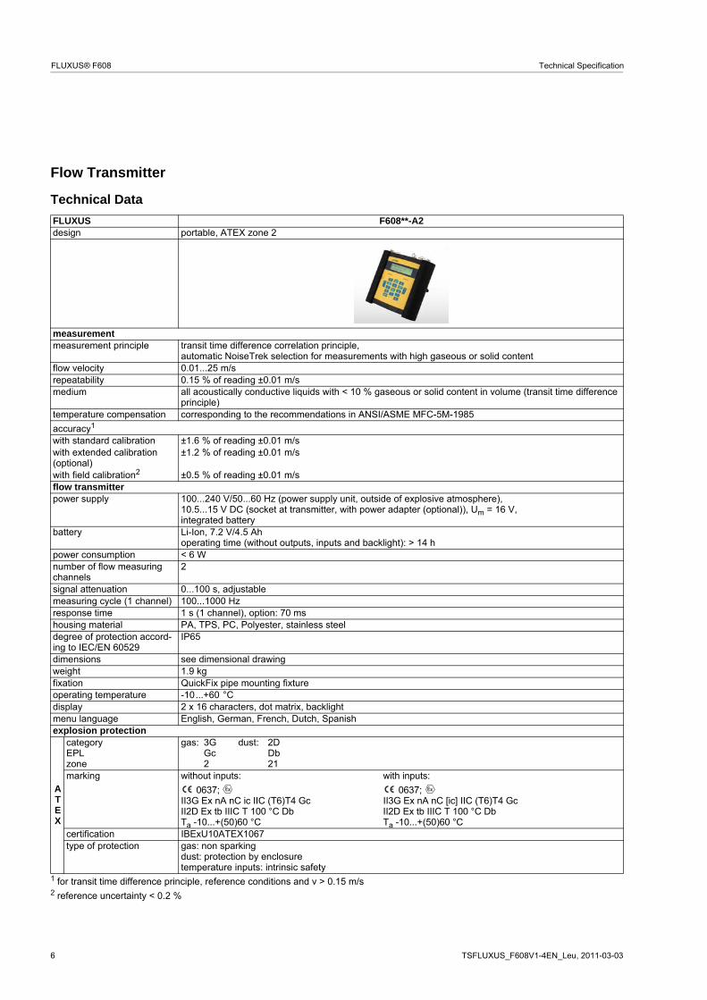
measuring functionsphysical quantities volumetric flow rate, mass flow rate, flow velocity,
heat flow (if temperature inputs are installed)totalizer volume, mass, optional: heat quantitycalculation functions average, difference, sumdiagnostic functions sound speed, signal amplitude, SNR, SCNR, standard deviation of amplitudes and transit timesdata loggerloggable values all physical quantities, totalized values and diagnostic valuescapacity > 100 000 measured valuescommunicationinterface RS232/USBserial data kitsoftware (all Windows™ ver-sions)
- FluxData: download of measurement data, graphical presentation,conversion to other formats (e.g. for Excel™)
- FluxKoef: creating medium data setsсable RS232adapter RS232 - USBtransport casedimensions 500 x 400 x 190 mmoutputs
The outputs are galvanically isolated from the transmitter.number see standard scope of supply on page 8accessories output adapter (optional)
current outputrange 0/4...20 mAaccuracy 0.1 % of reading ±15 μApassive output Uext = 4...9 V, depending on Rext
Rext < 200 Ωbinary output
optorelay 26 V/100 mAbinary output as alarm output- functions limit, change of flow direction or errorbinary output as pulse output- pulse value 0.01...1000 units- pulse width 1...1000 msinputs
The inputs are galvanically isolated from the transmitter.number see standard scope of supply on page 8
temperature inputtype Pt100/Pt1000connection 4-wirerange -150...+560 °C resolution 0.01 Kaccuracy ±0.01 % of reading ±0.03 Kintrinsic safety parameters Uo = 22 V, Io = 6 mA, Po = 33 mW, Co = 450 nF, Lo = 10 μH
Ci = 1.8 nF, Li = 10 μH
FLUXUS F608**-A2
8 TSFLUXUS_F608V1-4EN_Leu, 2011-03-03
FLUXUS® F608 Technical Specification
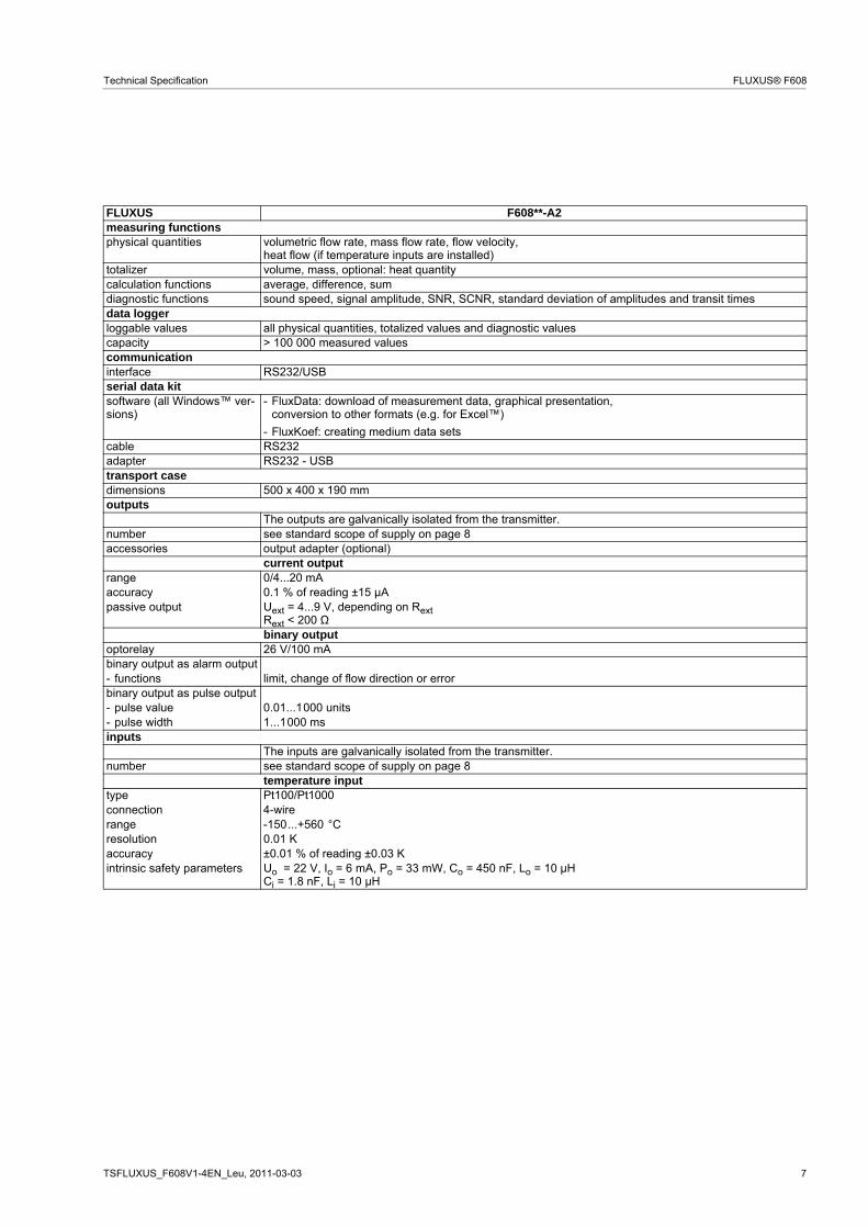
Dimensions
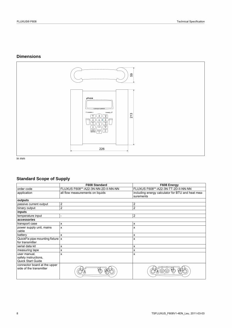
Standard Scope of Supply
in mm
F608 Standard F608 Energyorder code FLUXUS F608**-A22-3N-NN-2D-II-NN-NN FLUXUS F608**-A22-3N-TT-2D-II-NN-NNapplication all flow measurements on liquids including energy calculator for BTU and heat mea-
surementsoutputspassive current output 2 2binary output 2 2inputstemperature input - 2accessoriestransport case x xpower supply unit, mains cable
x x
battery x xQuickFix pipe mounting fixture for transmitter
x x
serial data kit x xmeasuring tape x xuser manual,safety instructions,Quick Start Guide
x x
connector board at the upper side of the transmitter
!
" # " $ %
226
5921
3
! $ ! "
& ' ( & '
! !
! $ ! "
& ' ( & '
! !
) ( & '

TSFLUXUS_F608V1-4EN_Leu, 2011-03-03 9
Technical Specification FLUXUS® F608
Adapters (optional)
Technical Data
output adapter power adaptertechnical type OA608A2 PA608A2dimensions see dimensional drawingweight kg 0.36 0.29materialhousing polyestergasket siliconedegree of protection according to IEC/EN 60529
IP66
operating temperaturemin. °C -20max. °C +90explosion protection
ATEX
zone 2marking
II3G Ex nA II T6 GcTa -20...+60 °C
type of protection non sparking
! $
& ' ( & '
! !
) ( & '
! "
output adapter
transducersmeasuring channel A
RS232 outputsinputs
transducersmeasuring channel B
power supply unit/battery charging unit
power adapter

10 TSFLUXUS_F608V1-4EN_Leu, 2011-03-03
FLUXUS® F608 Technical Specification
Dimensions
Terminal Assignment
output adapter power adapter
in mm
output adapter power adapter
110 55
75
55
75
80

TSFLUXUS_F608V1-4EN_Leu, 2011-03-03 11
Technical Specification FLUXUS® F608
Transducers
Transducer Selectiontransducer order code
FSK 100 200 3600 6500
FSM 50 100 2000 3400
FSQ 10 25 150 400
5 10 50 100 500 1000 5000inner pipe diameter [mm]
recommended possible

12 TSFLUXUS_F608V1-4EN_Leu, 2011-03-03
FLUXUS® F608 Technical Specification
Transducer Order Code
1, 2 3 4 5, 6 7, 8 9...11 12, 13 no. of character
tra
nsdu
cer
tra
nsdu
cer
fre
quen
cy
- oper
atin
g te
mpe
ratu
re
expl
osi
onpr
otec
tion
conn
ectio
nsy
stem
- exte
nsio
n ca
ble
/ optio
n
description
FS set of ultrasonic flow transducers for liquids measurement, shear wave
K 0.5 MHz
M 1 MHz
Q 4 MHz
N normal temperature range
E extended temperature range (shear wave transducers with trans-ducer frequency M, Q)
A1 ATEX zone 1
A2 ATEX zone 2
NL with Lemo connector
XXX cable length in m, for max. length of extension cable see page 20 (connector outside of ATEX zone 1)
LC long transducer cable (ATEX zone 2 (only FSK) andATEX zone 1)
example
FS M - N A2 NL - 030 shear wave transducer 1 MHz, normal temperature range, ATEX zone 2, connection system NL with Lemo connector and exten-sion cable 30 m
- - /

TSFLUXUS_F608V1-4EN_Leu, 2011-03-03 13
Technical Specification FLUXUS® F608
Technical Data
Shear Wave Transducers (zone 1)
technical type CDK1NW1 CLK1NW1 CDM2NW1 CLM2NW1order code FSK-NA1NL FSK-NA1NL/LC FSM-NA1NL FSM-NA1NL/LCtransducer frequency MHz 0.5 1
inner pipe diameter dmin. extended mm 100 50min. recommended mm 200 100max. recommended mm 3600 2000max. extended mm 6500 3400pipe wall thicknessmin. mm - -max. mm - -materialhousing PEEK with stainless steel cap and
transducer shoe 304 (1.4301)PEEK with stainless steel cap and
transducer shoe 304 (1.4301)contact surface PEEK PEEKdegree of protection according to IEC/EN 60529
IP65 IP65
transducer cabletype 1699 1699 1699 1699length m 5 9 4 9dimensionslength l mm 136.5 84width b mm 59 40height h mm 90.5 59dimensional drawing
operating temperaturemin. °C -40 -40max. °C +130 +130temperaturecompensation
x x
explosion protection
ATEX
transducer FSK-NA1NL FSK-NA1NL/LC FSM-NA1NL FSM-NA1NL/LCcategoryEPLzone
gas: 2/3G dust: 2D Gb/Gc Db 1/2 21
gas: 2/3G dust: 2D Gb/Gc Db 1/2 21
explosion protection temperature (pipe surface)min. °C -55 -55max. °C +180 +180marking 0637;
II2/3G Ex q nA IIC T6...T2 Gb/GcII2D Ex tb IIIC TX
0637; II2/3G Ex q nA IIC T6...T2 Gb/Gc
II2D Ex tb IIIC TXcertification IBExU10ATEX1162 X IBExU10ATEX1162 Xtype of protection gas: powder filling,
non sparkingdust: protection by enclosure
gas: powder filling,non sparking
dust: protection by enclosurenecessary trans-ducer mountingfixture
- -
l
hb
l
hb

14 TSFLUXUS_F608V1-4EN_Leu, 2011-03-03
FLUXUS® F608 Technical Specification
Shear Wave Transducers (zone 1)
technical type CDQ2NW1 CLQ2NW1order code FSQ-NA1NL FSQ-NA1NL/LCtransducer frequency MHz 4
inner pipe diameter dmin. extended mm 10min. recommended mm 25max. recommended mm 150max. extended mm 400pipe wall thicknessmin. mm -max. mm -materialhousing PEEK with stainless steel cap and
transducer shoe 304 (1.4301)contact surface PEEKdegree of protection according to IEC/EN 60529
IP65
transducer cabletype 1699 1699length m 3 9dimensionslength l mm 70width b mm 30height h mm 47.5dimensional drawing
operating temperaturemin. °C -40max. °C +130temperaturecompensation
x
explosion protection
ATEX
transducer FSQ-NA1NL FSQ-NA1NL/LCcategoryEPLzone
gas: 2/3G dust: 2D Gb/Gc Db 1/2 21
explosion protection temperature (pipe surface)min. °C -55max. °C +180marking 0637;
II2/3G Ex q nA IIC T6...T2 Gb/GcII2D Ex tb IIIC TX
certification IBExU10ATEX1162 Xtype of protection gas: powder filling,
non sparkingdust: protection by enclosure
necessary trans-ducer mountingfixture
-
l
hb

TSFLUXUS_F608V1-4EN_Leu, 2011-03-03 15
Technical Specification FLUXUS® F608
Shear Wave Transducers (zone 1, extended temperature range)
technical type CDM2EW5 CLM2EW5 CDQ2EW5 CLQ2EW5order code FSM-EA1NL FSM-EA1NL/LC FSQ-EA1NL FSQ-EA1NL/LCtransducer frequency MHz 1 4
inner pipe diameter dmin. extended mm 50 10min. recommended mm 100 25max. recommended mm 2000 150max. extended mm 3400 400pipe wall thicknessmin. mm - -max. mm - -materialhousing PI with stainless steel cap and
transducer shoe 304 (1.4301)PI with stainless steel cap and transducer shoe 304 (1.4301)
contact surface PI PIdegree of protection according to IEC/EN 60529
IP56 IP56
transducer cabletype 6111 6111 6111 6111length m 4 9 3 9dimensionslength l mm 84 70width b mm 40 30height h mm 59 47.5dimensional drawing
operating temperaturemin. °C -30 -30max. °C +200 +200temperaturecompensation
x x
explosion protection
ATEX
transducer FSM-EA1NL FSM-EA1NL/LC FSQ-EA1NL FSQ-EA1NL/LCcategoryEPLzone
gas: 2/3G dust: 2D Gb/Gc Db 1/2 21
gas: 2/3G dust: 2D Gb/Gc Db 1/2 21
explosion protection temperature (pipe surface)min. °C -45 -45max. °C +225 +225marking 0637;
II2/3G Ex q nA IIC T6...T2 Gb/GcII2D Ex tb IIIA TX
0637; II2/3G Ex q nA IIC T6...T2 Gb/Gc
II2D Ex tb IIIA TXcertification IBExU10ATEX1162 X IBExU10ATEX1162 Xtype of protection gas: powder filling,
non sparkingdust: protection by enclosure
gas: powder filling,non sparking
dust: protection by enclosurenecessary trans-ducer mountingfixture
- -
l
hb
l
hb

16 TSFLUXUS_F608V1-4EN_Leu, 2011-03-03
FLUXUS® F608 Technical Specification
Shear Wave Transducers (zone 2)
technical type CDK1NH1 CLK1NH1 CDM2NH1 CDQ2NH1order code FSK-NA2NL FSK-NA2NL/LC FSM-NA2NL FSQ-NA2NLtransducer frequency MHz 0.5 0.5 1 4
inner pipe diameter dmin. extended mm 100 100 50 10min. recommended mm 200 200 100 25max. recommended mm 3600 3600 2000 150max. extended mm 6500 6500 3400 400pipe wall thicknessmin. mm - - - -max. mm - - - -materialhousing PEEK with stainless steel
cap and transducer shoe 304 (1.4301)
PEEK with stainless steel cap and transducer shoe 304 (1.4301)
PEEK with stainless steel cap and transducer shoe 304 (1.4301)
PEEK with stainless steel cap and transducer shoe 304 (1.4301)
contact surface PEEK PEEK PEEK PEEKdegree of protection according to IEC/EN 60529
IP65 IP65 IP65 IP65
transducer cabletype 1699 1699 1699 1699length m 5 9 4 3dimensionslength l mm 136.5 136.5 84 70width b mm 59 59 40 30height h mm 90.5 90.5 59 47.5dimensional drawing
operating temperaturemin. °C -40 -40 -40 -40max. °C +130 +130 +130 +130temperaturecompensation
x x x x
explosion protection
ATEX
transducer FSK-NA2NL FSK-NA2NL/LC FSM-NA2NL FSQ-NA2NLcategoryEPLzone
gas: 3G dust: 2D Gc Db 2 21
gas: 3G dust: 2D Gc Db 2 21
gas: 3G dust: 2D Gc Db 2 21
gas: 3G dust: 2D Gc Db 2 21
explosion protection temperature (pipe surface)min. °C -55 -55 -55 -55max. °C +190 +190 +190 +190marking 0637;
II3G Ex nA IIC T6...T2 Gc XII2D Ex tb IIIC TX Db
0637; II3G Ex nA IIC T6...T2 Gc XII2D Ex tb IIIC TX Db
0637; II3G Ex nA IIC T6...T2 Gc XII2D Ex tb IIIC TX Db
0637; II3G Ex nA IIC T6...T2 Gc XII2D Ex tb IIIC TX Db
certification IBExU10ATEX1163 X IBExU10ATEX1163 X IBExU10ATEX1163 X IBExU10ATEX1163 Xtype of protection gas: non sparking
dust: protection by enclo-sure
gas: non sparkingdust: protection by enclo-sure
gas: non sparkingdust: protection by enclo-sure
gas: non sparkingdust: protection by enclo-sure
necessary trans-ducer mountingfixture
- - - -
l
hb
l
hb
l
hb
l
hb

TSFLUXUS_F608V1-4EN_Leu, 2011-03-03 17
Technical Specification FLUXUS® F608
Shear Wave Transducers (zone 2, extended temperature range)
technical type CDM2EH5 CDQ2EH5order code FSM-EA2NL FSQ-EA2NLtransducer frequency MHz 1 4
inner pipe diameter dmin. extended mm 50 10min. recommended mm 100 25max. recommended mm 2000 150max. extended mm 3400 400pipe wall thicknessmin. mm - -max. mm - -materialhousing PI with stainless steel cap
and transducer shoe 304 (1.4301)
PI with stainless steel cap and transducer shoe 304 (1.4301)
contact surface PI PIdegree of protection according to IEC/EN 60529
IP56 IP56
transducer cabletype 6111 6111length m 4 3dimensionslength l mm 84 70width b mm 40 30height h mm 59 47.5dimensional drawing
operating temperaturemin. °C -30 -30max. °C +200 +200temperaturecompensation
x x
explosion protection
ATEX
transducer FSM-EA2NL FSQ-EA2NLcategoryEPLzone
gas: 3G dust: 2D Gc Db 2 21
gas: 3G dust: 2D Gc Db 2 21
explosion protection temperature (pipe surface)min. °C -45 -45max. °C +235 +235marking 0637;
II3G Ex nA IIC T6...T2 Gc XII2D Ex tb IIIA TX Db
0637; II3G Ex nA IIC T6...T2 Gc XII2D Ex tb IIIA TX Db
certification IBExU10ATEX1163 X IBExU10ATEX1163 Xtype of protection gas: non sparking
dust: protection by enclo-sure
gas: non sparkingdust: protection by enclo-sure
necessary trans-ducer mountingfixture
- -
l
hb
l
hb
18 TSFLUXUS_F608V1-4EN_Leu, 2011-03-03
FLUXUS® F608 Technical Specification
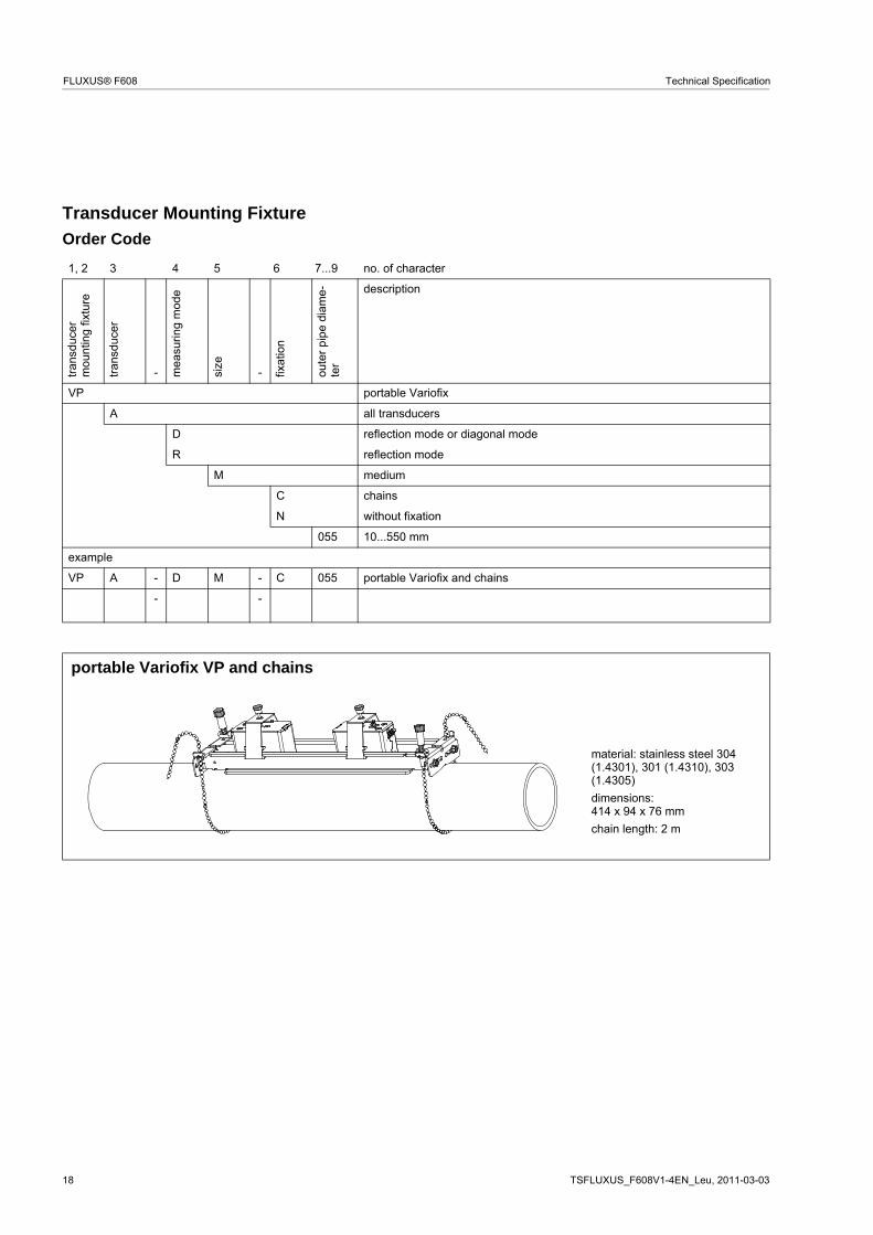
Transducer Mounting Fixture
Order Code
1, 2 3 4 5 6 7...9 no. of character
tra
nsdu
cer
mou
ntin
g fix
ture
tra
nsdu
cer
- mea
surin
g m
ode
size
- fixat
ion
oute
r pi
pe
dia
me-
ter
description
VP portable Variofix
A all transducers
D reflection mode or diagonal mode
R reflection mode
M medium
C chains
N without fixation
055 10...550 mm
example
VP A - D M - C 055 portable Variofix and chains
- -
portable Variofix VP and chains
material: stainless steel 304 (1.4301), 301 (1.4310), 303 (1.4305)
dimensions:414 x 94 x 76 mm
chain length: 2 m
TSFLUXUS_F608V1-4EN_Leu, 2011-03-03 19
Technical Specification FLUXUS® F608
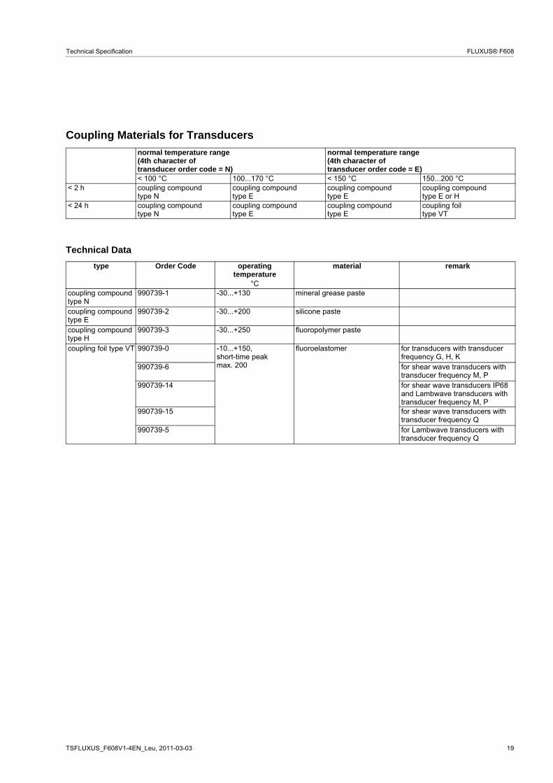
Coupling Materials for Transducers
Technical Data
normal temperature range(4th character oftransducer order code = N)
normal temperature range(4th character oftransducer order code = E)
< 100 °C 100...170 °C < 150 °C 150...200 °C< 2 h coupling compound
type Ncoupling compoundtype E
coupling compoundtype E
coupling compoundtype E or H
< 24 h coupling compoundtype N
coupling compoundtype E
coupling compoundtype E
coupling foiltype VT
type Order Code operating temperature
material remark
°Ccoupling compound type N
990739-1 -30...+130 mineral grease paste
coupling compound type E
990739-2 -30...+200 silicone paste
coupling compound type H
990739-3 -30...+250 fluoropolymer paste
coupling foil type VT 990739-0 -10...+150,short-time peak max. 200
fluoroelastomer for transducers with transducer frequency G, H, K
990739-6 for shear wave transducers with transducer frequency M, P
990739-14 for shear wave transducers IP68 and Lambwave transducers with transducer frequency M, P
990739-15 for shear wave transducers with transducer frequency Q
990739-5 for Lambwave transducers with transducer frequency Q

20 TSFLUXUS_F608V1-4EN_Leu, 2011-03-03
FLUXUS® F608 Technical Specification
Connection Systems
x, y - transducer cable length
l - max. length of extension cable
Transducer Cable
Technical Data
connection system NL
transducer frequency(3d character of
transducer order code)
G, H, K M, P Q S
NL
x y l x y l x y l x y lcable length m 2 3 ≤ 10 2 2 ≤ 10 2 1 ≤ 10 1 1 ≤ 10
cable length (option LC) m 2 7 ≤ 10 7 2 ≤ 10 8 1 ≤ 10 - - -
transducer cable extension cabletype 1699 6111 1750standard length m see table above see table above 5
10operating temperature °C -55...+200 -100...+225 < 80sheathmaterial stainless steel 304 (1.4301) stainless steel 304 (1.4301) stainless steel 304 (1.4301)outer diameter mm 8 8 9cable jacketmaterial PTFE PFA PEouter diameter mm 2.9 2.7 6thickness mm 0.3 0.5 0.5color brown white blackshield x x x
tran
smitt
er
l x y

TSFLUXUS_F608V1-4EN_Leu, 2011-03-03 21
Technical Specification FLUXUS® F608
Clamp-on Temperature Probe (optional)
Technical Data
Connection
Temperature Probe
Connector
Cable
order code 670415-1 670414-1 670415-2 670414-2design short response timetype Pt100 Pt100 matched according
to DIN 1434-1Pt100 Pt100 matched according
to DIN 1434-1connection 4-wire 4-wiremeasuring range °C -30...+250 -50...+250
accuracy T ±(0.15 °C + 2 . 10-3 . T [°C]), class A ±(0.15 °C + 2 . 10-3 . T [°C]), class Aaccuracy ΔT - ≤ 0.1 K
(3K < ΔT < 6 K), more corresponding to EN 1434-1
- ≤ 0.1 K(3K < ΔT < 6 K), more corresponding to EN 1434-1
response time s 50 8housing aluminum PEEK, stainless steel 304 (1.4301), copperdegree of protection according to IEC/EN 60529
IP66 IP66
weight (without con-nector)
kg 0.25 0.5 0.32 0.64
fixation clamp-on clamp-onaccessories - plastic protection plate,
insulation foamdimensionslength l mm 15 14width b mm 15 30height h mm 20 27dimensional drawing A A B
pin cable of temperature probe extension cable1 white/blue blue2 red/blue gray3, 4, 5 not connected6 red red7 white white8 not connected
cable of temperature probe extension cable
type 4 x 0.25 mm2 black or white LIYCY 8 x 0.14 mm2 graystandard length m 3 5/10max. length m - on requestcable jacket PTFE PVC
h
l
extension cable
h
l
A
B
red/blue red white/blue white

22 TSFLUXUS_F608V1-4EN_Leu, 2011-03-03
FLUXUS® F608 Technical Specification
FLEXIM GmbH
Wolfener Str. 36
12681 Berlin
Germany
Tel.: +49 (30) 93 66 76 60
Fax: +49 (30) 93 66 76 80
internet: www.flexim.com
e-mail: [email protected]
Subject to change without notification. Errors excepted.
FLUXUS® is a registered trademark of FLEXIM GmbH.