Embed Size (px)
Citation preview
Vol-III(TS) E13-ISOLATORS Page 1 of 23
ODISHA POWER TRANSMISSION CORPORATION LIMITED
TECHNICAL SPECIFICATION FOR
ISOLATORS
400KV HCB SINGLE ISOLATOR WITH 1 EARTH SWITCH
400KV HCB SINGLE ISOLATOR WITH 2 EARTH SWITCH
220KV SINGLE ISOLATOR WITHOUT EARTH SWITCH
220KV SINGLE ISOLATOR WITHEARTH SWITCH
220 KV TANDEM ISOLATOR
132 KV DOUBLE ISOLATOR WITH EARTH SWITCH
132 KV SINGLE ISOLATOR WITH EARTH SWITCH
132 KV SINGLE ISOLATOR WITHOUT EARTH SWITCH
132 KV TANDEM ISOLATOR
33 KV DOUBLE ISOLATOR WITH EARTH SWITCH
33 KV SINGLE ISOLATOR WITHOUT EARTH SWITCH
Vol-III(TS) E13-ISOLATORS Page 2 of 23
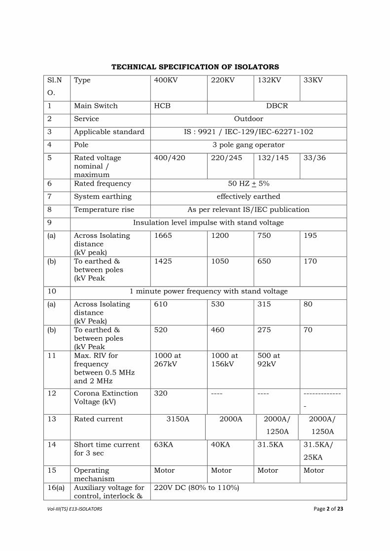
TECHNICAL SPECIFICATION OF ISOLATORS
Sl.N
O.
Type 400KV 220KV 132KV 33KV
1 Main Switch HCB DBCR
2 Service Outdoor
3 Applicable standard IS : 9921 / IEC-129/IEC-62271-102
4 Pole 3 pole gang operator
5 Rated voltage nominal / maximum
400/420 220/245 132/145 33/36
6 Rated frequency 50 HZ + 5%
7 System earthing effectively earthed
8 Temperature rise As per relevant IS/IEC publication
9 Insulation level impulse with stand voltage
(a) Across Isolating distance (kV peak)
1665 1200 750 195
(b) To earthed & between poles (kV Peak
1425 1050 650 170
10 1 minute power frequency with stand voltage
(a) Across Isolating distance (kV Peak)
610 530 315 80
(b) To earthed & between poles (kV Peak
520 460 275 70
11 Max. RIV for frequency between 0.5 MHz and 2 MHz
1000 at 267kV
1000 at 156kV
500 at 92kV
12 Corona Extinction Voltage (kV)
320 ---- ---- -------------
-
13 Rated current 3150A 2000A 2000A/
1250A
2000A/
1250A
14 Short time current for 3 sec
63KA 40KA 31.5KA 31.5KA/
25KA
15 Operating mechanism
Motor Motor Motor Motor
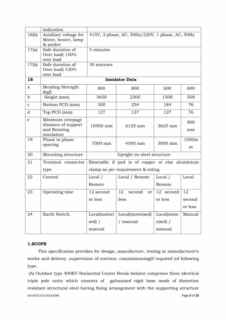
16(a) Auxiliary voltage for control, interlock &
220V DC (80% to 110%)
Vol-III(TS) E13-ISOLATORS Page 3 of 23
indication
16(b) Auxiliary voltage for Motor, heater, lamp & socket
415V, 3 phase, AC, 50Hz/220V, 1 phase, AC, 50Hz
17(a) Safe duration of Over load( 150% over load
5 minutes
17(b) Safe duration of Over load( 120% over load
30 minutes
18 Insulator Data
a Bending Strength (kgf)
800 800 600 600
b Height (mm) 3650 2300 1500 508
c Bottom PCD (mm) 300 254 184 76
d Top PCD (mm) 127 127 127 76
e Minimum creepage distance of support and Rotating insulators
10500 mm 6125 mm 3625 mm 900
mm
19 Phase to phase spacing 7000 mm 4500 mm 3000 mm
1500m
m
20 Mounting structure Upright on steel structure
21 Terminal connector
type
Bimetallic if pad is of copper or else aluminium
clamp as per requirement & rating ratingaluminium clamp as per requirement & rating.
22 Control Local /
Remote
Local / Remote Local /
Remote
Local
23 Operating time 12 second
or less
12 second or
less
12 second
or less
12
second
or less
24 Earth Switch Local(motori
zed) /
manual
Local(motorized)
/ manual
Local(moto
rized) /
manual
Manual
1.SCOPE
This specification provides for design, manufacture, testing at manufacturer‟s
works and delivery ,supervision of erection, commissioning(if required )of following
type.
(A) Outdoor type 400KV Horizontal Centre Break Isolator comprises three identical
triple pole units which consists of galvanized rigid base made of distortion
resistant structural steel having fixing arrangement with the supporting structure
Vol-III(TS) E13-ISOLATORS Page 4 of 23
and also having two rotating bearing unit on both sides each base with
interconnecting pipe fixing clamps for tandem and link pipe. Porcelain insulators
made of composite stacks of rated capacity carrying male & female contact
assembly are fixed on the rotating bearing unit of base of each pole. Two units of
each pole interconnected by link pipes & finally, all three pole are connected to
group operating pipe. Movement of group operating pipe for closing & opening
operation of isolator is done by Down pipe connected to the operating
mechanism(Motor/Manual). Thus, all three poles of the Isolator shall be
mechanically gang operated by a common operating mechanism to ensure that
operations of all three poles are simultaneous.
Double Earth Switch should be provided i.e one on Male side & another on
Female side. On each side, E/S of all three poles are mechanically ganged with one
common motor operating mechanism.
The earthing switches should be of non-ferrous materials especially of the same
material as that of main switch assembly and able to carry the same fault current
as assigned to the main disconnector and withstand the dynamic stresses.
If corona extinction voltage is to be achieved with the help of corona ring or any
other similar device, the same shall be deemed to be included in the scope of the
Supplier.
For each set of Isolator, two sets of clamp connector i.e. one set of clamp
connector suitable for 4 inch bus bar & onset of clamp connector suitable for twin
moose shall be deemed to be included in the scope of the supplier.
(B) The 220,132 & 33 KV Isolators shall be outdoor type with three phase double
break centre rotating type [ Single(SI) / Double(DI) ] Isolators suitable for electrical
as well as manual operation and local/remote operation. They shall have crank
and reduction gear mechanism. Isolator rated for above 72.5 kV shall be of
extended mechanical endurance class - M2 as per IEC-62271-102. Isolator rated
for 72.5 kV and below shall be of extended mechanical endurance class - M1 as per
IEC-62271-102. All earth switches shall be of M0 duty. All Isolators offered shall be
suitable for horizontal upright mounting on steel structures. Each pole unit of the
multiple Isolators shall be of identical construction and mechanically linked for
gang operation.
Outdoor type 220KV /132KV /33KV, 3 phase triple pole double break gang
operated centre rotating type (Single / Double) Isolator with / without earth
Vol-III(TS) E13-ISOLATORS Page 5 of 23
switches, with electrical inter lock, insulators and complete in all respect with
bimetallic / aluminium connectors arcing horns operating mechanism, auxiliary
switches, indicating devices, fixing detail etc. as described herein after.
Each pole of the Isolator shall be provided with two sets of contacts to be
operated in series and the moving contact blades shall rotate in horizontal plane.
The design shall be such that the operating mechanism with the linkages shall be
suitable for mounting on any of the outer pole ends without much difficulty and
with minimum shifting of parts.
Moving contacts of all isolators shall rotate through 90 deg from their “fully closed
position” to “fully open position so that the break is distinct and clearly visible from
ground level.
The Isolators offered by the Bidder shall be designed for Normal rating current for
Isolator 400kV 220 kV 132 kV 33kV
3150A 2000A 2000A/1250A 2000A/1250A
It should suitable for continuous service at the system voltages specified
herein. The Isolators shall be suitable to carry the rated current continuously and
full short circuit current of 63/40/31.5/25 KA for 400/220/132/33 KV
respectively for 3 second at site condition without any appreciable rise in
temperature. These shall also be suitable for operation at 110% rated (normal)
voltage. The Isolators shall be suitable for Isolating low capacitive / inductive
currents of 0.7amp at 0.15 power factor. The isolators shall be so constructed that
they don‟t open under the influence of short circuit conditions.
The Isolators and earthing switches are required to be used on electrically
exposed installation and this should be taken into account while fixing the
clearance between phases and between phase and earth.
2. STANDARDS
Disconnecting switches covered by this specification shall conform to latest
edition IEC- 62271-102 and unless specifically stated otherwise in this
specification.
1. MAIN CONTACTS
All Isolators shall have heavy duty, self-aligning and high pressure line type
contacts made of high conductivity, corrosion resistant, hard-drawn electrolytic
copper strips of proper thickness and contact area. Contacts should consist of
Vol-III(TS) E13-ISOLATORS Page 6 of 23
loops of above copper strips suitable for 2000 Amps ratings. The hard dawn
electrolytic copper strips should be silver plated 25 micron thickness and fixed
contacts should be backed by powerful phosphor bronze/stainless steel springs of
suitable numbers. However, the thickness and contact area of the contact should
conform to the drawing approved during type test. Moving contact with moving arm
should be of hard-drawn electrolytic copper of proper thickness and contact area
for all isolators. However, in case of 400KV HCB Isolator, the moving arms (except
the contacts) may be of tubular aluminium of proper cross sectional area. These
fixed and moving contacts shall be able to carry the rated current continuously and
the maximum fault current of 63/40/31.5/25 KA for 400/200/132/33KV
respectively for 3 seconds without any appreciable rise in temperature. The Isolator
blades shall retain their form and straightness under all conditions of operation
including all mechanical stress arising out of operation as well as under rated short
circuit condition.
Fixed guides shall be provided so that even when the blades are out of
alignment by one inch (maximum), closing of the switches, proper seating of the
blades in between contacts and adequate pressure to give enough contact surface
is ensured. Wherever possible, the blades shall be counter balanced by weights and
springs. The contact shall be self cleaning by the wiping action created by the
movements of the blades. The surface of the contacts shall be Bided smooth and
silver plated ( 25 micron).
The Isolator shall be self-cleaning type so that when isolators remain closed for
long periods in a heavily polluted atmosphere, binding does not occur. No undue
wear or scuffing shall be evident during the mechanical endurance tests, contacts
and springs shall be designed so that adjustment of contact pressure shall not be
necessary throughout the life of the isolator. Each contact or part of contacts shall
be independently sprung so that full pressure is maintained on all contact at all
times.
2. ARCING HORN AND GRADING HORN
Suitable arcing horn made of tinned electrolytic copper which are required
for guiding contacts shall be provided on the fixed and moving contacts of all
Isolators. The contacts shall be of „make before and break after” type.
3. ELECTRICAL INTERLOCK / MECHANICAL INTERLOCK
The disconnecting switches whenever required shall be with an approved type
electrical interlock for interlocking with the associated circuit breakers and earth
switch. Electrical interlock assembly should be more right in construction and
Vol-III(TS) E13-ISOLATORS Page 7 of 23
properly mounted to ensure reliable operation. The design should be such that the
electrical circuit for the interlocking mechanism will only remain energised during
operation of the switches.
4. AUXILIARY SWITCHES
All isolators and earthing switches shall be provided with 220V DC auxiliary
switches for their remote position indication on the control board and for electrical
locking with other equipment. The auxiliary switch shall be provided with a
minimum of ten auxiliary contacts-10 normally open and 10 normally closed and
10 normally open and 10 normally closed for earth switch. Separate auxiliary
switches shall be provided for isolating and earth switches. 6 additional NO and NC
contact to be provided as spare in each case.
The auxiliary switches and auxiliary circuits shall have a continuous current
carrying capacity of at least 10 Amps. Auxiliary switches shall not be used as limit
switches. Details of make, rating and type of limit switch shall be furnished in the
offer.
5. EARTH SWITCH
Line earth switch shall consist of three earthing blades for Isolator which normally
rest against the frame when the connected Isolator is in closed position. The
earthing blades for three phase shall be mechanically linked to a coupling shaft
which shall be capable of being fitted on either side of the Isolator. The earthing
blades shall match and be similar to the main switch blades and shall be provided
at the hinge; with suitable flexible conductors at all moving points with terminal
lugs to maintain a continuous path to the station ground bus. The earthing blades
shall be operated by a separate mechanism but shall be mechanically interlocked
with the main switch so that the earthing blades can be closed only when the main
switches are in open position and vice-versa. The earthing blades shall be gang
operated and all the three blades will operate simultaneously. 245 kV earth
switches shall also comply with the requirements of IEC-62271-102, in respect of
induced current switching duty as defined for Class-B and short circuit making
capability class E-0 for earthing switches.
6. OPERATING MACHANISM
The operating mechanism shall be simple and shall ensure quick and effective
1000 operation. The design shall be such as to enable one man to operate it with
nominal effort. The operating mechanism box shall be made out of aluminum
extruded (Aluminum alloy) sections of minimum 3.0 mm thickness. The operating
mechanism shall be strong rigid and not subject to rebound.
Vol-III(TS) E13-ISOLATORS Page 8 of 23
The Isolator blades shall be in positive continuous control throughout the entire
cycles of operation. The operating rods and pipes shall be rigid enough to maintain
positive control under most adverse conditions and to withstand all torsional and
bending stresses arising from operation. Operation of the switches at any speed
should not result in improper functioning, in displacement of parts / machines
after final adjustment has been made. All holes in cranks, linkages etc. having
moving pins shall be drilled and fitted accurately so as to prevent slackness and
lost motion.
Provision shall be made for padlocking the operating mechanism of disconnecting
and earth switches in both open and closed positions.
Bearings shall be ball and roller type shall be protected from weather and dust by
means of cover and grease retainers. Bearings pressures shall be kept low to
ensure long life and care of operation.
Each power operated isolator shall be motor driven as well as manually operated
and shall be complete with local / remote selector switch and open / close push
buttons. The function of all control facilitates operating isolators.
Provision shall be made in the control cabinet to disconnect power supply to
prevent local / remote power operation. Limit switches for open and close positions
of isolators shall be provided.
All the terminal blocks to be used in the operating mechanism should of stud type
of Poly-amide/Mealmine material of make like Elmex (OAT-6 for non disconnecting
type & OAT –6T for disconnecting type) / connectwell ( Equivalent).
7. DESIGN, MATERIALS AND WORKMANSHIP
The live parts shall be designed to eliminate sharp points, edges and similar corona
producing surfaces. Where this is impracticable, adequate shields to be provided.
All ferrous metal parts shall be hot dip galvanized, as per IS 2629.All metal parts
shall be of such materials or treated in such a way so as to avoid rust, corrosion
and deterioration due to continued exposure to atmosphere and rain. All current
carrying parts shall be made from high conductivity electrolytic copper /
aluminium.
Bolts, screws and pins shall be provided with standard locking device viz.
Locknuts, spring washers, keys etc. and when used with current carrying parts,
they shall be made of copper silicon or other high conductivity and wear resistant
alloys.
Vol-III(TS) E13-ISOLATORS Page 9 of 23
The switches should not need lubrication of any parts except at very long interval of
five year minimum.
8. PROTECTIVE COATINGS
All ferrous parts including bolts, nuts and washers of the switches assembly shall
be galvanised to withstand at least six one minute dips in copper sulphate solution
of requisite strength (Prece tests) except the threaded portions which should
withstand four dips.
9. Insulators – Support insulators for all type of isolators shall be of solid core
type. The insulator shall be made of homogeneous and vitreous porcelain of
high mechanical and dielectric strength. It shall have sufficient mechanical
strength to sustain electrical and mechanical loading on account of wind
load, short circuit forces etc. Glazing of the porcelains shall be of uniform
dark brown colour with a smooth surface arranged to shed away rain water.
The porcelain shall be free from laminations and other flaws or imperfections
that might affect the mechanical or dielectric quality. It shall be thoroughly
vitrified, tough and impervious to moisture. The porcelain and metal parts
shall be assembled in such a manner and with such material that any
thermal differential expansion between the metal and porcelain parts
throughout the range of temperature specified in this specification shall not
loosen the parts or create under internal stresses which may affect the
mechanical or electrical strength or rigidity. The assembly shall not have
excessive concentration of electrical stresses in any section or across leakage
surfaces. The cement used shall not give rise to chemical reaction with metal
fittings. The insulator shall be suitable for water washing by rain or artificial
means in service condition. Profile of the insulator shall also conform to IEC-
815. Insulator shall have a minimum cantilever strength of 800 kgf (for
400Kv, 220 Kv ) & 600 Kgf for (132KV,33 Kv ). Caps to be provided on top of
the insulator shall be of high grade cast iron or malleable steel casting. It
shall be machine faced and hot dip galvanized. The cap shall have four
numbers of tapped holes spaced on a pitch circle diameter of 127mm. The
holes shall be suitable for bolts with threads having anti corrosive
protection. The effective depth of threads shall not be less than the nominal
diameter of the bolt. The cap shall be so designed that it shall be free from
visible corona and shall have radio interference level within 500 micro volts
for 220 Kv & 132 Kv .Casing shall be free from blow holes cracks and such
other defects
Vol-III(TS) E13-ISOLATORS Page 10 of 23
If corona extinction voltage is to be achieved with the help of corona
ring or any other similar device, the same shall be deemed to be
included in the scope of the Supplier
10. Control Cabinet: The control cabinet of the operating mechanism shall be
made out of minimum 3mm thick aluminium alloy sheet. Hinged door shall
be provided with pad locking arrangement. Flexible earthing strips to be
provided for moving shaft connecting to the isolator with cabinet body as
well as the hinged door with main body. Sloping rain hood shall be provided
to cover all sides. 15 mm thick neoprene or better type of gaskets shall be
provided to ensure degree of protections of at least IP 55 as per IS 2147/IS-
3947. The cabinet shall be suitable for mounting on support structure with
adjustment for vertical, horizontal and longitudinal alignment. Details of
these arrangements shall be furnished alongwith the offer.
11. Motor : Motors rated 1 Kw and above shall be suitable for operation on 3
phase, 415 V, 50 HZ supply. Motors of lower rating shall be single phase
type suitable for 240V, 50HZ system. It shall be totally enclosed type if
mounted outside the control cabinet. The motor shall withstand without
damage stalled torque for atleast 3 times the time lag of tripping device. The
motor shall, in all other respects, conform to the requirement of I.S. 325.
12. Gear : The dis-connector / isolator may be required to operate occasionally,
with considerably long idle intervals. Special care shall be taken for selection
of material for gear and lubrication of gears to meet this requirement. The
gear shall be made out of aluminium bronze or any other better material
lubricated for life with graphite or better quality non-drawing and non-
hardening type grease. Wherever necessary automatic relieving mechanism
shall be provided suitable relay, Device shall be provided to prevent over
loading of the motor. Single phase preventer (for 3 phase meter) shall be
provided to operate on open circuiting of any phase and shall trip off the
motor. Complete details of the devices shall be furnished in the offer.
13. Space heaters : Space heaters suitable for 1 phase 240V AC supply shall be
provided for each motor operated operating mechanism to prevent
condensation and shall be operated by MCB.
14. Terminal block and Wirings – Each operating mechanism shall be provided
with 1100V grade stud type terminal block. All auxiliary switches, interlocks
and other terminals shall be wired upto terminal block. The terminal block
Vol-III(TS) E13-ISOLATORS Page 11 of 23
shall have at least 20% extra terminals. All wiring shall be carried out with
1.1KV grade insulated 2.5 sq mm copper wires.
15. Interior Illumination : A holder suitable for a 240 V lamp shall be provided in
each of the motor operated mechanism of three poles & shall be door
operated type.
16. Control and auxiliary supply – A 3 phase switch with MCB for phases and
link for neutral, shall be provided for power supply and a 2 pole MCB shall
be provided for control supply.
17. Position indicator : A position indicator to show the isolator is in ON or OFF
position to be provided.
18. Name plate : Isolator, earthing switches and their operating devices shall be
provided with name plate. The name plate shall be weather proof and
corrosion proof. It shall be mounted in such a position that it shall be visible
in the position of normal service and installation. It shall carry the following
informations duly engraved or punched on it.
A. Isolator Base
Name : OPTCL
Name of manufacturer –
Order No. –
Type Designation –
Manufacturers serial No. –
(Confirming to IS)
Rated voltage –
Rated normal current –
Rated short time current (rms) and duration –
Rated short time peak current (KAP)
Weight
B. B. Earthing Switch
Name : OPTCL
Name of manufacturer –
Order No. –
Type Designation –
Manufacturers serial No. –
(Confirming to IS)
Rated voltage –
Vol-III(TS) E13-ISOLATORS Page 12 of 23
Rated normal current –
Rated short time current (rms) and duration
Rated short time peak current (KAP)
Weight
C. Operating Device
Name – OPTCL
Name of manufacturer –
Order No.
Type Designation –
Reduction gear ratio –
AC motor
i) Rated auxiliary voltage
ii) Starting current
iii) Designation of AC motor as per I.S 4722/325
iv) Starting torque at 80% of supply voltage
v) Over travel in degrees after cutting off supply
Total operating time in seconds
i) Close operation – Electrical
ii) Open operation – electrical
Open operation – manual
19. Painting Galvanizing and Climate Proofing
At interiors and exteriors of enclosures, cabinets and other metal parts
(other than made up of aluminium) shall be thoroughly cleaned to remove all rust,
scales, corrosion, grease and other adhering foreign matter and the surfaces
treated by phosphating (e.g. seven tank phospating sequence). After such
preparation of surfaces, two coats of zinc oxide primer shall be given by suitable
stoving and air drying before final painting. Colour of the final paints shall be of
shade no. 697 of IS:5. The finally painted cubicle shall present aesthetically
pleasing appearance free from any dent or uneven surface.
Paint inside the metallic housing shall be of anti condensation type and the paint
on outside surfaces shall be suitable for outdoor installation.
All components shall be given adequate treatment of climate proofing as per
IS:3202 so as to withstand corrosive and severe service conditions.
Vol-III(TS) E13-ISOLATORS Page 13 of 23
All metal parts not suitable for painting such as structural steel, pipes, rods ,levers,
linkages, nuts and bolts used in other than current path etc. shall be hot dip
gaivanised as per IS –2629. Galvanisation test will be carried out during routine
test.
Complete details of painting, galvanising and climate proofing of the equipment
shall be furnished in the offer.
24. TESTS
Type Tests
Isolators offered, shall be fully type tested as per the relevant standards. The
Bidder shall furnish Three sets of the following valid type test reports for their
different type of offered Isolators along with the offer. The Purchaser reserves the
right to demand repetition of some or all the type tests in the presence of
purchaser‟s representative. For this purpose the Bidder may quote unit rates for
carrying out each type test and this will be taken during bid price evaluation ,if
required.
a) Short time withstand & peak withstand current test for Isolator & Earth Switch.
b) Power frequency (Dry & Wet),Lightening Impulse dry withstand Test
c) Mechanical endurance Test ( M2 class).
d) IP-55 test.
e) Temperature rise.
f) Seismic withstand test.
g) Induced current test (Class-B)as per IEC 62271-102. (For 220 KV class
Isolators).
h) RIV test. (132 KV & above).
During type tests the isolator shall be mounted on its own support structure or
equivalent support structure and installed with its own operating mechanism to
make the type tests representative. Drawing of equivalent support structure and
mounting arrangements shall be furnished for Purchaser‟s approval before
conducting the type tests.
The type tests shall be conducted on the isolator along with approved insulators
and terminal connectors.
Mechanical endurance test shall be conducted on the main switch as well as earth
switch of one isolator of each type.
Acceptance and Routine Test :
All acceptance and routine test as stipulated in the relevant standards shall be
carried out by the supplier in presence of Purchaser‟s representative.
Vol-III(TS) E13-ISOLATORS Page 14 of 23
Mechanical operation test (routine test) shall be conducted on isolator (main switch
and earth switch) at the supplier‟s works as well as purchaser‟s substation site.
Immediately after finalisation of the programme of type / acceptance, routine
testing the supplier shall give sufficient advance intimation (clear 20 days advance
intimation), along with shop routine test certificates, valid calibration reports from
Govt. approved test house for the equipments, instruments to be used during
testing for scrutiny by the purchaser to enable him to depute his representative for
witnessing the tests. If there will be any discrepancies in the shop routine test
certificates and calibration reports furnished by the firm then after settlement of
the discrepancies only, purchaser‟s representative will be deputed for witnessing
the tests.
Special tests proposed to be conducted (if decided to conduct ) as type test on
isolators, are given at Annexure- II. These special type test charges shall be quoted
alongwith all other type tests as per relevant IEC standard and these charges shall
be included in the total bid price.
Test certificates of various items including but not limited to the following shall be
furnished at the time of routine tests.
a) Chemical analysis of copper alongwith a copy of excise certificate
indicating genuine source of procurement of electrolytic grade copper.
b) Bearings
c) Fasteners
d) Universal / swivel joint coupling
e) Insulators
f) Motor
g) Gears
h) Auxillary switch
i) Limit switch
j) Timer
k) Overload / single phase preventer relay
l) Interlocking devices
m) Terminal block
n) Any other item
25. INSPECTION
i) The Purchaser shall have access at all times to the works and all other places of
manufacture, where the disconnectors, earth switches and associated equipment
are being manufactured and the supplier shall provide all facilities for unrestricted
Vol-III(TS) E13-ISOLATORS Page 15 of 23
inspection of the works raw materials manufacture of all the accessories and for
conducting necessary tests as detailed herein.
ii) The supplier shall keep the purchaser informed in advance of the time of
starting of the progress of manufacture of equipment in its various stages
so that arrangements could be made for inspection.
iii) No material shall be dispatched from its point of manufacture unless the
material has been satisfactorily inspected and tested.
iv) The acceptance of any quantity of the equipment shall in no way relieve
the supplier of his responsibility for meeting all the requirements of this
specification and shall not prevent subsequent rejection if such
equipment are later found to be defective.
26 QUALITY ASSURANCE PLAN
The Bidder shall invariably furnish following information alongwith his
offer, failing which his offer shall be liable for rejection.
(i) Names of sub suppliers for raw materials, list of standards according to
which the raw materials are tested, list of tests normally carried out on
raw materials in presence of Supplier‟s representative, copies of test
certificate
(ii) Information and copies of test certificates as in (I) and (ii) above in respect
of bought out accessories.
(iii) List of manufacturing facilities available
(iv) Level of automation achieved and lists of areas where manual processing
still exists.
(v) List of areas in manufacturing process, where stage inspections are
normally carried out for quality control and details of such tests and
inspections.
List of testing equipments with calibration certificates from Govt. approved test
house available with supplier for final testing equipment and test plant limitation if
any, vis-à-vis the type, special acceptance routine test specified in the relevant
standards. These limitations shall be very clearly brought out in the specified test
requirements.
The supplier shall within 30 days of placement of order, submit following
information to the purchaser.
i) List of raw material as well as bought out accessories and the names of
sub-suppliers selected from the lists furnished alongwith offer.
Vol-III(TS) E13-ISOLATORS Page 16 of 23
ii) Type test certificates of the raw material and both bought out accessories.
iii) Quality Assurance Plan (QAP) with hold points for purchaser‟s inspection.
The supplier shall submit the routine test certificates of bought out accessories and
raw material viz. Copper, aluminium conductors, lubricating material, gear
material etc. at the time of routine testing of the fully assembled isolator.
27. DOCUMENTATION
All drawings shall conform to relevant international standards organisation (ISO).
All drawings shall be in ink and suitable for micro filming. All dimensions and data
shall be in S.I. Units.
List of Drawings and Documents
The Bidder shall furnish four sets of following drawings / documents along
with his offer.
a) General outline and assembly drawings of the dis-connector operating
mechanism, structure, insulator and terminal connector.
b) Sectional views and descriptive details of items such as moving blades,
contacts, arms contact pressure, contact support bearing housing of
bearings, balancing of heights, phase coupling pipes, base plate, operating
shaft, guides, swivel joint operating mechanism and its components etc.
c) Loading diagram
d) Drawings with structure for the purpose of type tests.
e) Name plate.
f) Schematic drawing.
g) Type test reports.
h) Test reports, literature, pamphlets of the bought out items and raw
material.
The supplier shall within 2 weeks of placement of order submit four sets of final
versions of all the above said drawings for Purchaser‟s approval. The purchaser
shall communicate his comments / approval on the drawings to the supplier. The
supplier shall, if necessary, modify the drawings and resubmit four copies of the
modified drawings for Purchaser‟s approval within two weeks from the date of
comments. After receipt of approval the supplier shall within three weeks submit
15 prints and two good quality re-producibles of the approved drawings for
purchaser‟s use.
Six sets of the type test reports, duly approved by the Purchaser shall be submitted
by the supplier for distribution, before commencement of supply Adequate copies of
Vol-III(TS) E13-ISOLATORS Page 17 of 23
acceptance and routine test certificates, duly approved by the Purchaser shall
acompany the despatched consignment.
The manufacturing of the equipment shall be strictly in accordance with the
approved drawings and no deviation shall be permitted without the written
approval of the purchaser. All manufacturing and fabrication work in connection
with the equipment prior to the approval of the drawing shall be at the supplier
risk.
28. INSTRUCTION MANUALS :
Fifteen copies of the erection, operation and maintenance manuals in English be
supplied for each type of disconnector one month prior to despatch of the
equipment. The manual shall be bound volumes and shall contain all drawings and
information required for erection, operation and maintenance of the disconnector
including but not limited to the following particulars.
(a) Marked erection prints identifying the component parts of the disconnector
as shipped with assembly drawings.
(b) Detailed dimensions and description of all auxiliaries.
(c) Detailed views of the insulator stacks, metallics, operating mechanism,
structure, interlocks, spare parts etc.
29. PACKING AND FORWARDING.
The equipment shall be packed in crates suitable for vertical / horizontal transport,
as the case may be and suitable to withstand handling during transport and
outdoor storage during transit. The supplier shall be responsible for any damage to
the equipment during transit, due to improper and inadequate packing. The easily
damageable material shall be carefully packed and marked with the appropriate
caution symbols. Wherever necessary, proper arrangement for lifting, such as
lifting hooks etc. shall be provided. Any material found short inside the packing
cases shall be supplied by supplier without any extra cost.
Each consignment shall be accompanied by a detailed packing list containing
the following information :
(a) Name of the consignee.
(b) Details of consignment.
(c) Destination.
(d) Total weight of consignment.
(e) Handling and unpacking instructions.
(f) Bill of material indicating contents of each package.
Vol-III(TS) E13-ISOLATORS Page 18 of 23
The supplier shall ensure that the bill of material is approved by the purchaser
before despatch.
30. SUPERVISION OF ERECTION TESTING AND COMMISSIONING (ET & C)
Purchaser proposes to utilize the services of the supplier for supervision of
testing and commissioning of the equipment being supplied by him, if it is required.
For this purpose, the supplier should make available the services of trained
personnel (Engineers) who shall correct in the field, any errors or omissions in
order to make the equipment and material properly perform in accordance with the
intent of this specification. The Engineer shall also instruct the plant operators in
the operation and maintenance of the commissioned equipment. The supplier shall
be responsible for any damage to the equipment on commissioning the same, if
such damage results for the faulty or improper ET&C. Purchaser shall provide
adequate number of skilled / semi skilled workers as well as ordinary tools and
equipment and cranes required for equipment errection, at his own expenses. Apart
from the above, the Purchaser shall not be responsible for providing any other
facilties to the supplier. Special tools if required for erection and commissioning
shall be arranged by the supplier at his cost and on commissioning these shall be
supplied to the purchaser free of cost for future use.
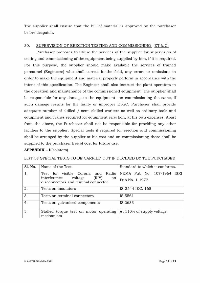
APPENDIX – I(Isolators)
LIST OF SPECIAL TESTS TO BE CARRIED OUT IF DECIDED BY THE PURCHASER
Sl. No. Name of the Test Standard to which it conforms.
1. Test for visible Corona and Radio interference voltage (RIV) on
disconnectors and teminal connector.
NEMA Pub No. 107-1964 ISRI
Pub No. 1-1972
2. Tests on insulators IS-2544 IEC. 168
3. Tests on terminal connectors IS:5561
4. Tests on galvanised components IS:2633
5. Stalled torque test on motor operating mechanism
At 110% of supply voltage
Vol-III(TS) E13-ISOLATORS Page 19 of 23
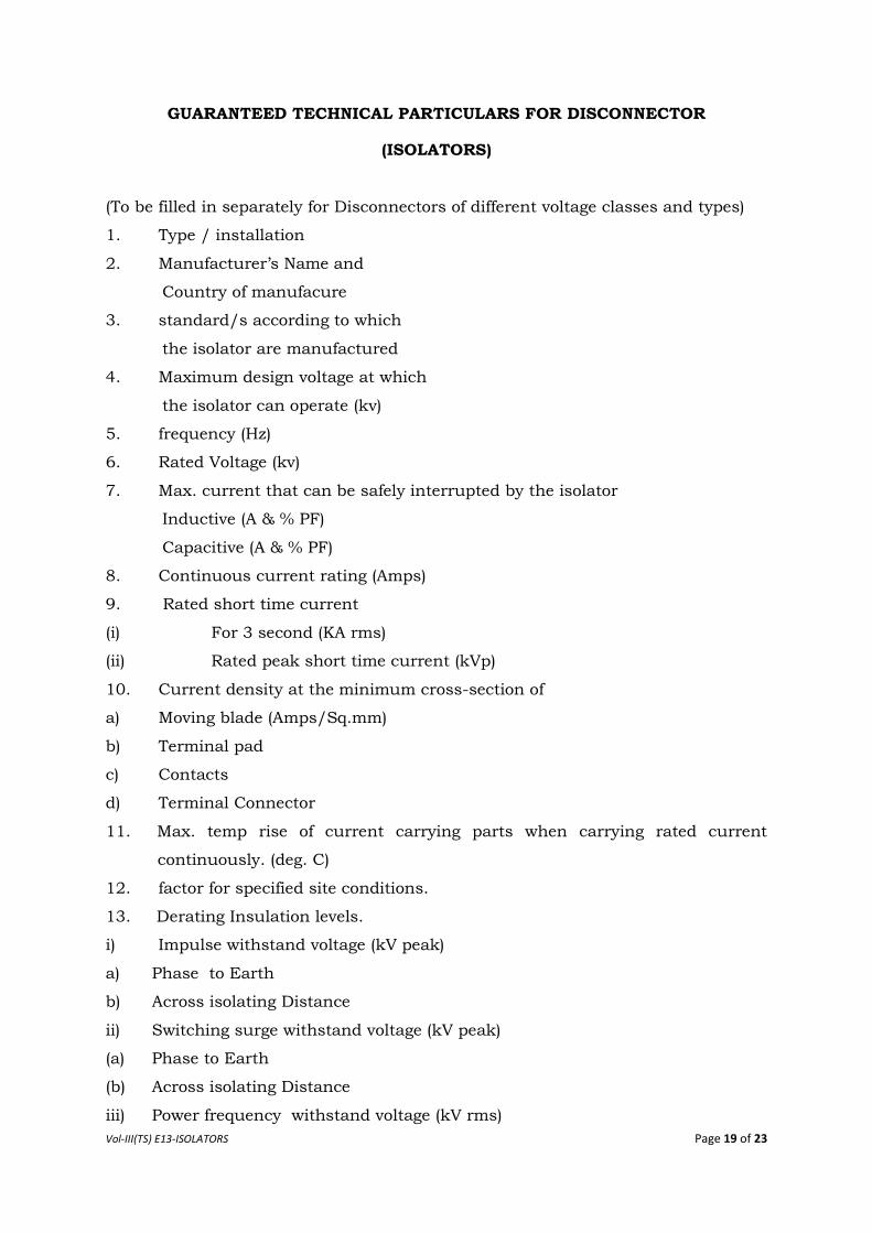
GUARANTEED TECHNICAL PARTICULARS FOR DISCONNECTOR
(ISOLATORS)
(To be filled in separately for Disconnectors of different voltage classes and types)
1. Type / installation
2. Manufacturer‟s Name and
Country of manufacure
3. standard/s according to which
the isolator are manufactured
4. Maximum design voltage at which
the isolator can operate (kv)
5. frequency (Hz)
6. Rated Voltage (kv)
7. Max. current that can be safely interrupted by the isolator
Inductive (A & % PF)
Capacitive (A & % PF)
8. Continuous current rating (Amps)
9. Rated short time current
(i) For 3 second (KA rms)
(ii) Rated peak short time current (kVp)
10. Current density at the minimum cross-section of
a) Moving blade (Amps/Sq.mm)
b) Terminal pad
c) Contacts
d) Terminal Connector
11. Max. temp rise of current carrying parts when carrying rated current
continuously. (deg. C)
12. factor for specified site conditions.
13. Derating Insulation levels.
i) Impulse withstand voltage (kV peak)
a) Phase to Earth
b) Across isolating Distance
ii) Switching surge withstand voltage (kV peak)
(a) Phase to Earth
(b) Across isolating Distance
iii) Power frequency withstand voltage (kV rms)
Vol-III(TS) E13-ISOLATORS Page 20 of 23
(a) Phase to Earth
(b) Across isolating distance
iv) Radio interference voltage at 1.1 times maximum line to ground voltage
(micro volts)
v) Corona inception voltage (kV rms)
vi) Corona extinction voltage (KV rms)
14. Minimum clearance in air:
i) Between poles (mm)
ii) Between live parts and earth (mm)
iii) Between live part when switch is open
(a) On the same pole (mm)
(b) Between adjacent poles (mm)
15. Rated mechanical terminal load
i) Load along the terminal connector side (kg)
ii) Load across the terminal connector side(kg)
16. Torque required to operate the switch in Kg. m.
14. Contact zone
(i) Horizontal deflection (mm)
(ii) Vertical deflection (mm)
(iii) Total amplitude of longitudinal movement w.r.t. conductor supporting fixing
contact (mm)
15. Design and Construction
i) No. of Insulators per pole
ii) Contacts
a) Material and grade
b) Cross-sectional area in sq.mm
iii) Moving Blades
a) Material and grade
b) Cross sectional area
iv) Contact Support
a) Material and size of channel / block
b) Material and size of plate
v) Rain hood – Material grade and size
vi) Turn and twist mechanism
a) Material and size of clamps
b) Material and size of springs
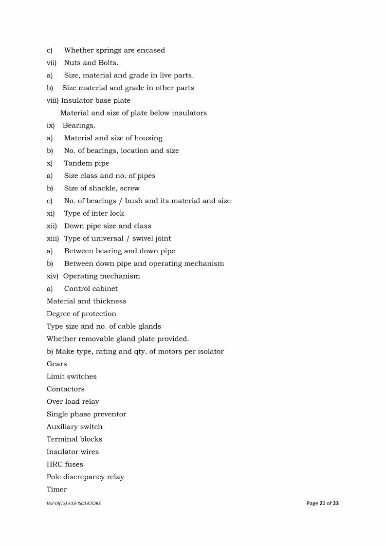
Vol-III(TS) E13-ISOLATORS Page 21 of 23
c) Whether springs are encased
vii) Nuts and Bolts.
a) Size, material and grade in live parts.
b) Size material and grade in other parts
viii) Insulator base plate
Material and size of plate below insulators
ix) Bearings.
a) Material and size of housing
b) No. of bearings, location and size
x) Tandem pipe
a) Size class and no. of pipes
b) Size of shackle, screw
c) No. of bearings / bush and its material and size
xi) Type of inter lock
xii) Down pipe size and class
xiii) Type of universal / swivel joint
a) Between bearing and down pipe
b) Between down pipe and operating mechanism
xiv) Operating mechanism
a) Control cabinet
Material and thickness
Degree of protection
Type size and no. of cable glands
Whether removable gland plate provided.
b) Make type, rating and qty. of motors per isolator
Gears
Limit switches
Contactors
Over load relay
Single phase preventor
Auxiliary switch
Terminal blocks
Insulator wires
HRC fuses
Pole discrepancy relay
Timer
Vol-III(TS) E13-ISOLATORS Page 22 of 23
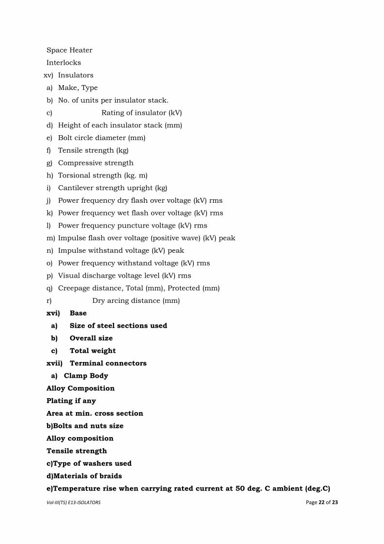
Space Heater
Interlocks
xv) Insulators
a) Make, Type
b) No. of units per insulator stack.
c) Rating of insulator (kV)
d) Height of each insulator stack (mm)
e) Bolt circle diameter (mm)
f) Tensile strength (kg)
g) Compressive strength
h) Torsional strength (kg. m)
i) Cantilever strength upright (kg)
j) Power frequency dry flash over voltage (kV) rms
k) Power frequency wet flash over voltage (kV) rms
l) Power frequency puncture voltage (kV) rms
m) Impulse flash over voltage (positive wave) (kV) peak
n) Impulse withstand voltage (kV) peak
o) Power frequency withstand voltage (kV) rms
p) Visual discharge voltage level (kV) rms
q) Creepage distance, Total (mm), Protected (mm)
r) Dry arcing distance (mm)
xvi) Base
a) Size of steel sections used
b) Overall size
c) Total weight
xvii) Terminal connectors
a) Clamp Body
Alloy Composition
Plating if any
Area at min. cross section
b)Bolts and nuts size
Alloy composition
Tensile strength
c)Type of washers used
d)Materials of braids
e)Temperature rise when carrying rated current at 50 deg. C ambient (deg.C)
Vol-III(TS) E13-ISOLATORS Page 23 of 23
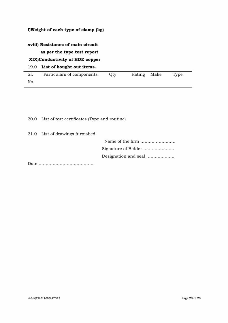
f)Weight of each type of clamp (kg)
xviii) Resistance of main circuit
as per the type test report
XIX)Conductivity of HDE copper
19.0 List of bought out items.
Sl.
No.
Particulars of components Qty. Rating Make Type
20.0 List of test certificates (Type and routine)
21.0 List of drawings furnished.
Name of the firm …………………….
Signature of Bidder ………………….
Designation and seal ………………..
Date …………………………………