Embed Size (px)
Citation preview

TEİAŞ-İHTD/2018-048.0
TECHNICAL SPECIFICATION FOR SPECIAL CONDUCTORS
The original version of this technical specification has been prepared in Turkish and in case of any inconsistency between English and Turkish, the Turkish language shall prevail.
PREPARATIONS : DECEMBER 2018

TEİAŞ
TEİAŞ-İHTD/2018-048.0 i Technical Specification for Special
Conductors
TECHNICAL SPECIFICATION FOR SPECIAL CONDUCTORS
1. GENERAL .............................................................................................................. 1
1.1. Subject and Scope ............................................................................................ 1 1.2. Standards .......................................................................................................... 2 1.3. Operational Conditions ...................................................................................... 4
1.3.1. Special Conductor Conditions ................................................................... 4
1.3.2. Current Carrying Capacity Conditions ....................................................... 5 1.3.3. Sag – Strain Conditions ............................................................................. 6 1.3.4. Conductor Clearance Conditions ............................................................... 7
1.4. Incompliance with Warranties and Deviations ................................................... 7 2. TECHNICAL CHARACTERISTICS ........................................................................ 7
2.1. Conductor Types ............................................................................................... 7 2.2. Electrical and Mechanical Characteristics ......................................................... 8 2.3. Structural Characteristics .................................................................................. 9
2.3.1. Additional Information Specific to Conductor Type .................................. 10 2.3.2. Conductor System Design ....................................................................... 10 2.3.3. Grease & Surface Treatments ................................................................. 11
2.4. Information, Documents and Calculations ....................................................... 12
2.4.1. Information, Documents .......................................................................... 12 2.4.2. Calculations ............................................................................................. 13
2.5. Diagrams ......................................................................................................... 13 2.5.1. Tension-Elongation Curves ..................................................................... 13
2.5.2. Creep- Time Curves ................................................................................ 13 2.5.3. Long Period Creep – Time Curves .......................................................... 13
2.6. Reel ................................................................................................................. 13
2.7. Nameplate ....................................................................................................... 14 3. TESTS .................................................................................................................. 15
3.1. Type Tests ...................................................................................................... 15
3.1.1. Surface Condition .................................................................................... 16
3.1.2. Conductor diameter – Internal Space Measurement ............................... 16 3.1.3. D.C Resistance........................................................................................ 16
3.1.4. Inertness .................................................................................................. 16 3.1.5. Lay Ratio and Direction of Lay ................................................................. 17 3.1.6. Number and Type of Wires ...................................................................... 17 3.1.7. Mass per Unit Length of Conductor and Grease ..................................... 17
3.1.8. Stress-Strain (Elongation ) Curve Test .................................................... 17 3.1.9. Tensile Breaking Strength ....................................................................... 18 3.1.10. Stringing Test ........................................................................................ 18 3.1.11. Surface Emissivity ................................................................................. 18
3.2. Tests on Individual Wires ................................................................................ 19
3.2.1. Surface Condition .................................................................................... 19 3.2.2. Diameter .................................................................................................. 19
3.2.3. Mechanical Characteristics Tests ............................................................ 20 3.2.4. Resistivity (Aluminium & Aluminium Alloy Wires Only) ............................ 20 3.2.5. Wrapping Test (Galvanised Steel, Aluminium & Aluminium Alloy Wires Only) .................................................................................................................. 21 3.2.6. Welding (Aluminium & Aluminium Alloy Wires Only) ............................... 21
3.2.7. Zinc Coating Tests (Galvanised Steel Wires Only) .................................. 21

TEİAŞ
TEİAŞ-İHTD/2018-048.0 ii Technical Specification for Special
Conductors
3.2.8. Aluminium Cladding Thickness and Uniformity (Aluminium Clad Steel Wires Only) .................................................................................................................. 22 3.2.9. Torsion Test (Zinc Coated Steel & Aluminium Clad Steel Wires Only) .... 22
3.2.10. Dye Penetration Test (Solid Composite Core Conductors Only) ........... 23 3.2.11. Corona Extinction Voltage Test ............................................................. 23
3.2.12. Radio Interference Voltage Test ............................................................ 23 3.2.13. High Temperature Endurance & Creep Test ......................................... 23 3.2.14. Sheaves Test......................................................................................... 24 3.2.15. Axial Impact Test ................................................................................... 24 3.2.16. Radial Crush Test .................................................................................. 24
3.2.17. Aeolian Vibration Test ........................................................................... 25 3.2.18. Torsional Ductility Test .......................................................................... 25 3.2.19. Temperature Cycle Test ........................................................................ 25 3.2.20. Heat Resistance Test On Aluminium Alloy Wire .................................... 26 3.2.21. Bending test on Aluminium clad core wire (if applicable) ....................... 26
3.2.22. Compression test on Aluminium clad wires (if applicable) ..................... 26 3.2.23. Coefficient of linear expansion for core wire/ core wires ........................ 27
3.2.24. Strand Brittle fracture test (for carbon-fibre composite core only) ......... 27
3.3. Tests on Grease .............................................................................................. 27 3.3.1. High Temperature Stability Tests ............................................................ 27 3.3.2. Corrosive Substances in Grease ............................................................. 28
3.4. Sample Tests .................................................................................................. 28 3.4.1. Routine Inspection ................................................................................... 28
4. FORMS AND RECORDS ..................................................................................... 28
ANNEX-1 TEİAŞ STANDARD PHASE CONDUCTORS SAG DISTANCES .......... 30 ANNEX-2 TEİAŞ STANDARD STEEL CORE ALUMINUM CONDUCTOR CHARACTERISTICS (DATASHEET) ...................................................................... 33 ANNEX-3 TEİAŞ STANDARD PHASE CONDUCTORS CURRENT CARRYING CAPACITIES ............................................................................................................ 35
ANNEX-4 A TYPE TESTS APPLICABLE ON THE CONDUCTOR AND CONDUCTIVE MATERIAL ...................................................................................... 36 ANNEX- 4 B SAMPLE TESTS APPLICABLE ON THE CONDUCTOR and CONDUCTIVE MATERIAL ...................................................................................... 40 ANNEX-5 Minimum Tensile Strengths, Elongation and Stress at 1% Values .... 42
ANNEX-6 LIST OF MATERIALS ............................................................................. 43 ANNEX-7 LIST OF WARRANTED CHARACTERISTICS – TECHNICAL PARAMETERS ........................................................................................................ 44 ANNEX-8 LIST OF DEVIATIONS ............................................................................ 46 ANNEX-9 CONDUCTOR SECTION DRAWING ...................................................... 47

TEİAŞ
TEİAŞ-İHTD/2018-048.0 1 Technical Specification for Special
Conductors
TECHNICAL SPECIFICATION FOR SPECIAL CONDUCTORS
1. GENERAL 1.1. Subject and Scope These specifications define the technical and general characteristics and performance characteristics for the design, production and tests of the conductors to be used in 170 kV and 420 kV Power Transmission Lines (ACSR, ACAR, AAC, AAAC, AACSR) and conductors with thermal resistance and low sag (ACSS, TACIR, TACSR, GZTACSR, ACCR and ACCC) in the transmission system. It also includes the conditions for supply and use. In these specifications, all conductors except the existing ACSR conductors being used by our Enterprise, are called as special conductors. If the internal and external layers of the conductors consist of different materials, the internal layer of the conductor is called as the core of the conductor. The technical characteristics of the conductors, which are requested to be provided, are indicated below. Basic Areas of Use of High Temperature Low Sag (HTLS) Special Conductors: 1) Where it is not possible to construct new lines, creating higher capacity energy corridors by using the existing posts 2) Even if new line construction is possible, use of similar weight higher capacity conductors at the points, where the posts are new but the conductor is low-capacity 3) Where it is not possible to erect higher posts due to any reason, capacity increase is ensured by using special conductors suitable for the existing post type for solving the encountered clearance problems. Special conductors have advannameplatees such as: increasing the current carrying capacity under appropriate conditions in general, being economic in long period, lowering sagging distance, decreasing the voltage drop, nationalization and right of way areas, minimizing line losses, being designed so as to prevent icing and increasing energy supply security (N-1) etc.
General Conditions: These conductors must be designed taking into consideration the conditions in Annex 2 for replacing the ASCR conductors on the existing power transmission lines with the purpose of increasing the current carrying capacities of the lines without exceeding the maximum sagging and maximum tension values to be applied on the posts that are indicated in Annex-1. Special conductor producers must show such production of them in their quality management systems.

TEİAŞ
TEİAŞ-İHTD/2018-048.0 2 Technical Specification for Special
Conductors
All conductors and conductor systems must comply with the requirements of the relevant standards and the additional conditions indicated in these specifications. As a part of the Type Registration operation for the conductors, the Conductor supplier has to propose appropriate hardware (Dead End Assemblies, Helical Suspension Units, Suspension Clamps, Spacers and Vibration Dampers etc.) suppliers wherever possible. The Contractor shall completely submit the PLSCAD files related with the proposed conductors to the DIRECTORATE. 1.2. Standards
The design, production and tests of the conductors included in the scope of these specifications shall be performed in compliance with the latest editions of the Standards.
Standard No Standard Name
TS-EN ISO 9001 Quality Management System Certificate
ASTM B 230 Standard Specification for Aluminium 1350-H 19 Wire For Electrical Purposes(Elektrikî Amaçlar İçin 1350-H 19 Alüminyum Tel İçin Standart)
ASTM B 232 Standard Specification for Aluminium Conductors, Coated-Steel Reinforced(ACSR)(Çelik Özlü Alüminyum İletkenler İçin Standart)
ASTM B 498 Standard Specification for Zinc-coated (Galvanized)Steel Core Wire For Aluminium Conductors (Alüminyum İletkenler İçin Çinko Kaplı(Galvanizlenmiş) Çelik İçin Standart)
TS EN 50182
Conductors for Overhead Lines-Round wire concentric lay stranded conductors(Havai Hat İletkenleri-Yuvarlak Telli Eşmerkez Tabakalı Örgülü İletkenler)
TS EN 50183 Conductors For Overhead Lines Alumınıum-Magnesıum-Sılıcon Alloy Wıres (Havai Hat İletkenleri- Alüminyum –Magnezyum-Silisyum Alaşımlı İletkenler)
TS EN 50189 Zinc-coated Steel Wires For Overhead Lines (Hava Hattı İletkenleri İçin Çinko Kaplanmış Çelik Teller)
TS EN 60889 Conductors for Overhead Lines - Hard-drawn Aluminium Conductor(Hava Hattı İletkenleri –Sert Çekilmiş Alüminyum Tel) (ACCC iletkenleri için sadece test edilme şartları)
TS EN 62004 Thermal-resistant aluminium alloy wire for overhead line conductor.
EN 62420 Concentric lay stranded overhead electrical conductors containing one or more gap(s).
TS EN 50326 Conductors for Overhead Lines – Characteristics of Grease for Bare Overhead Line Conductors Havai Hatlar İçin İletkenler - Havai Hat İletkenleri için Gres Yağının Özellikleri
IEC 61232 Aluminium clad steel wires for electrical purposes Elektrik amaçlı alüminyum kaplı çelik teller
IEC 61597 Overhead electrical conductors – Calculation methods for stranded bare conductors

TEİAŞ
TEİAŞ-İHTD/2018-048.0 3 Technical Specification for Special
Conductors
Havai elektrik iletkenleri - Telli çıplak iletkenler için hesaplama yöntemleri
TS EN 10244-2 Steel wire and wire products – Non-ferrous metallic coatings on steel wire Çelik tel and tel ürünleri - Çelik tel üzerinde demir dışı metalik kaplamalar
TR 50540
Havai hatlar için İletkenler- Alüminyum iletken çelik destekli (ACSS İletkenler İçin) (ACCC iletkenleri için çelik öz gereksinimleri bölümleri hariç diğer bölümleri tabidir)
IEC 60468 Metalik Malzemelerin Direncinin Ölçüm Yöntemleri
EN 61395 Overhead electrical conductors - Creep test procedures for stranded conductors. Havai elektrik iletkenleri - Telli iletkenler için Creep testi prosedürleri
ASTM B987 ACCC iletkenleri için Karbon Fiber kompozit özün (CFCC) elektrik yüklü havai iletkenlerde kullanılması için standart özellikleri
ASTM B 856/B /B 857M
Standard Specification for Concentric-Lay-Stranded Aluminum Conductors, Coated Steel Supported (ACSS) (Konsantrik,sıkı bükümlü Örgülü Alüminyum İletkenler için Standart Şartname, Kaplanmış Çelik Destekli)
IEC 61089-AM1/97
Havai Hat İletkenleri-Yuvarlak telli konsantrik,sıkı bükümlü Örgülü İletkenler (Round wire concentric lay overhead electrical stranded conductors )
The conductors shall be produced in compliance with Turkish Standards, EN, IEC and ASTM standards. The Producer shall indicate the standards taken as basis in the list of warranted characteristics in Annex 7. Although the relevant standards are referred to in these specifications, it is also possible to use standards that are equivalent or superior to the standards that are defined in those standards. If other equivalent or superior standards are proposed, their copies in Turkish and English shall be provided together with the bid. The Contractor shall list all valid international standards being used in relation with the proposed conductors. The original sets of those standards shall be submitted to the employer by the Contractor. In case there are differences between TSE and ASTM, EN or IEC Standards, written permission shall be obtained from the Purchaser to determine which standard will be applied. The steel core of ACSR conductor shall be produced in compliance with ASTM B 498 or TS EN 50189 and shall be coated using class A zinc. When ASTM B 232 Standard is applied for ACSR conductor, ASTM B 498 shall be applied for the steel core or when TS EN 50182 is applied for the conductor, TS EN 50189 shall be applied for the values of the steel core after the braid.

TEİAŞ
TEİAŞ-İHTD/2018-048.0 4 Technical Specification for Special
Conductors
The number and diameter of the wires in each conductor for ACSR, ACAR, AAC, AAAC and AACSR conductors must be compliant with the conditions indicated in TS EN 50182. 1.3. Operational Conditions
1.3.1. Special Conductor Conditions
The nominal continuous operational temperatures for special conductors are as follows: ACSR, ACAR, AAC, AAAC and AACSR 80 °C ACCC, ACSS, ACFR Up to 180 °C GZTACSR, (Z)TACIR Up to 170 °C Maximum provisional operational temperatures for special conductors are as follows: ACSR, ACAR, AAC, AAAC and AACSR 100 °C ACCC, ACSS, ACFR Up to 200 °C ZTACSR, (Z)TACIR Up to 250 °C Attention must be paid to the fact that there may be temperature rises up to 35 ° C above the nominal operational temperatures of ACSR & AAAC conductors in case of failure conditions occurring later. While ACCC conductors can reach temperatures that are 40 ° C above their rated temperatures, GZTACSR conductors can reach temperatures that are 40 ° C higher than their nominal operational temperatures. The proposed HTLS conductor must comply with the following minimum requirements: The general diameter of the proposed conductor must not be more than the relevant existing conductor indicated in the Conductor Datasheet (Annex 2).
- The sagging values of the special conductors must not be more than the sagging values of the existing conductor (Annex 1).
- The special conductors must provide the requested current carrying capacity on the line, where it will be used.
- It shall be warranted that the special conductor shall not exceed the DC resistance at 20 ° C and the AC resistance under the relevant conditions given on the Conductor Datasheet in Annex-2 in comparison with the existing conductor, which will be replaced with it.
The Contractor shall submit the analysis certificates giving the percennameplatee and nature of any pollution on the metal used for producing the wires. There shall not be joints on individual wires of the external layers of aluminum wires. The winding of all layers shall be produced within a single production process.

TEİAŞ
TEİAŞ-İHTD/2018-048.0 5 Technical Specification for Special
Conductors
The datasheet of special conductors, the Materials List, List of Warranted Characteristics – List of Technical Parameters and Conductor section drawing and detailed comparison tables showing the sagging values between it and the conductor, which it will replace, the current and power carrying capacities at different temperatures, the resistance values and other matters shall be submitted to the DIRECTORATE by the Bidder. The detailed characteristics of the proposed conductor(s) shall be completed by the Contractor in line with the Warranted Characteristics – Technical Parameters of the Conductor given in Annex-7. 1.3.2. Current Carrying Capacity Conditions
The Contractor shall show that the Special Conductor is capable of complying with the indicated Current Carrying Capacity requirements (for continuous operation). If ACSR Hawk, Drake, Cardinal conductors are replaced with a special conductor that is equivalent to Pheasant, that special conductor shall comply with the current carrying values under summer, spring and thermal conditions. If it is necessary to carry additional current in addition to the conductors used by TEİAŞ, such current value shall be separately notified to the Contractor by the DIRECTORATE. Special Conductor Current Carrying Capacity shall be calculated basing on the following conditions and TSE IEC /TR 3 61597 Standard. Parameters used for the calculation of relevant current carrying capacities with aluminum conductors; Environmental conditions accepted by TEİAŞ: Summer- Conductor Temperature 80 °C - Air Temperature 40 °C - Wind rate 0,1m/s Spring - Conductor Temperature 80 °C - Air Temperature 25 °C - Wind Rate 0,5m/s Thermal- Conductor Temperature 80 °C - Air Temperature 40 °C- Wind Rate 0,25m/s Other parameters to be used for current carrying calculations are as follows:
PARAMETER VALUE
Solar radiation 1000 W/m2
Emissivity coefficient in respect to black housing
0.6
Solar radiation absorption coefficient 0.5
Wind angle 90 degrees
Elevation 1000 meters
1. Çevre Sıcaklığı ( Ambient temperature) T1 = 293 K (equal to 20 °C): In compliance with these Operational Conditions, the current carrying capacities of the existing ACSR conductors accepted by TEİAŞ are given in detail in ANNEX -3. Detailed current amount calculations for all proposed special conductors shall be provided as a part of the bid for all conditions included in Annex2 and Annex 3. The
TEİAŞ
TEİAŞ-İHTD/2018-048.0 6 Technical Specification for Special
Conductors
calculation must clearly indicate the conductor temperature degree, at which the necessary ampere degrees are obtained. The numbers defined with calculations shall be declared in the relevant articles of the Conductor data page and Warranted Characteristics – Technical parameters list. The conductor design shall be suitable for operation at the steady state Conductor Temperature corresponding to the thermal, summer, spring capacities requested for that conductor. The Contractor shall also indicate the maximum Conductor Temperature permitted for continuous operation without any deterioration in the electrical, mechanical and metallurgic characteristics and the capacity corresponding to the maximum temperature permitted under the above ambient conditions. The Contractor shall provide the maximum Conductor Temperature permitted for short period operation including the period permitted for short period operation. The current carrying capacities corresponding to that temperature under the ambient conditions indicated above shall also be indicated.
The ambient conditions of power transmission lines are accepted as follows.
- Height : under 1000 m - Ambient temperature (*)
Maximum : +45 °C
Minimum : - 40 °C
24-hour average : under +35 °C
Annual average : not exceeding +25°C - Ambient air pollution : heavy - Wind pressure : 53-68 kg / m² - Maximum solar radiation : 1000 W / m² (*) For the installations at locations, where the ambient temperature can be
excessively out of the normal operational conditions indicated above, the minimum and maximum temperature preferred ranges that must be indicated are;
- for very cold climate: -50°C and +40°C - for very hot climate: -5°C and +50°C
1.3.3. Sag – Strain Conditions
The Contractor shall show that the sagging of the existing conductor will never exceed the relevant sagging of the existing conductor under the sag-strain conditions indicated in Annex-1 and Annex-2. The Special Conductor sagging must be calculated for the Conductor Temperature at which the indicated current Carrying Capacity is obtained (calculated in accordance with the previous paragraph) and must be compared as follows with the sagging of the existing conductor at 80 ° C operational temperature:

TEİAŞ
TEİAŞ-İHTD/2018-048.0 7 Technical Specification for Special
Conductors
The sagging – strain calculations (digital and printed copy) must be submitted. It is compulsory. Furthermore, the Contractor must confirm that the sagging of the existing protection wire under any weather condition (maximum operational temperature, minimum operational temperature, -5 ° C, ice load, etc.) will be less than the sagging of the Special conductor.
As indicated in ANNEX-1, the sagging tables shall be provided for all ice load regions and for openings up to 700 meters starting from 200 meters and increasing with 100 meter steps.
Sagging at -5 °C Ice + Wind (m)
Sagging at 5 °C Iced Conductor (m)
Sagging at +15 °C on naked conductor (m)
Sagging at +45/40 °C naked conductor (m)
1.3.4. Conductor Clearance Conditions
The Contractor must ensure that the minimum distances of the special conductor, that is the distances between the conductors, between phase- ground wire and between the conductor and the towers are within the permitted limits. 1.4. Incompliance with Warranties and Deviations The matters mentioned in the Technical Specifications and the values given in the Warranted Characteristics Lists have to be one-to-one complied with. In case of incompliance, the bidder shall clearly indicate the deviations in the list given in Annex-8. The List of Deviations, which is completed by the Bidder/ Contractor shall be assessed by the Directorate in terms of its compliance with the essence of the Technical Specifications and the relevant standards. The sanctions to be applied on the Contractor or the Producer in case the deviations that are assessed and approved by the Purchaser can not be complied with during the acceptance of the conductor shall be determined by the Purchaser. 2. TECHNICAL CHARACTERISTICS
2.1. Conductor Types
High Voltage Overhead Line Conductors:
ACSR/(ACS)(TW) – Aluminium Conductor Steel Reinforced ACAR – Aluminium Conductor Alloy Reinforced AAC – All Aluminium Conductor

TEİAŞ
TEİAŞ-İHTD/2018-048.0 8 Technical Specification for Special
Conductors
AAAC – All Aluminium Alloy Conductor AACSR – Aluminium Alloy Conductor Steel Reinforced
High temperature Low Sag High Voltage Overhead Line Conductors: (HTLS – High Temperature Low Sag)
ACSS/(ACS)(TW) – Aluminium Conductor Steel Supported (Z)TACIR – (Zirconium Alloy) Thermal resistant Aluminium Conductor Invar Reinforced TACSR –Thermal resistant Aluminium Conductor Steel Reinforced G(Z)TACSR – “Gap” type Thermal resistant Aluminium Conductor Steel Reinforced ACCC/(TW) - Aluminium Conductor Composite Core ACCR - Aluminium Conductor Composite Reinforced ACFR - Aluminium Conductor Fiber Reinforced
ACS = Aluminium Clad Steel Wire TW = Trapezoidal Wires Z = Zirconium Alloy
The frequently used special conductors are given as example here. There are also other special conductor types. 2.2. Electrical and Mechanical Characteristics
Unless otherwise specified in the Materials List and/or List of Warranted Characteristics, the conductors shall be suitable for operation under the following conditions. Maximum system voltage (kV rms) : 170 420 Rated current (A) : As indicated in the Materials List Rated frequency (**) (Hz) : 50 50 Rated short time withstand current (for 1s)(kA rms): 31.5 63 Rated peak withstand current (kA peak): 80 125 Mechanical Strength : in accordance with the material list (**) The conductors shall be designed for continuous operation in 47.5-52 Hz range, for minimum 20 seconds at each input in 47-47.5 Hz range.

TEİAŞ
TEİAŞ-İHTD/2018-048.0 9 Technical Specification for Special
Conductors
If the voltage at with the conductor/ conductors included in the scope of the order will be used is not indicated, the examination of the conductor/ conductors shall be performed in accordance with the heaviest conditions in electrical and mechanical aspects. The characteristics of the steel core aluminum conductors that are being used by TEİAŞ are given in ANNEX-2 Table. 2.3. Structural Characteristics The diameter of the conductor braid and the conductor layers of the braid shall be arranged so as to be opposite to the direction of winding of the lower layer. The conductor wire shall be resistant against the strains during wire laying. The step direction of the outer layer shall be in the right hand direction. Steel, aluminum and aluminum alloy wires must be pre-formed and/or post-formed to ensure that remain fixed and that they do not move in accordance with each other when the conductor is cut. The pre-forming and/or post-forming method that is used must not cause damage to the galvanizing of wires or steel wires The complete conductor and its sections shall be free from dirt, burrs and foreign materials, shall be newly produced and shall be unused. The surface of the conductor must not contain peel-offs, cuts or defects that may create audible noise due to corona production at operational voltage. Smooth compression ellipses up to 3 mm are acceptable in aluminum or aluminum alloy of the round wire conductor windings on the inner layers of conductors. Precautions must be taken during the production, storage and delivery of the conductors in order to prevent fragility, corrosion of aluminum or aluminum alloy wires and to prevent contamination with any other material, for example copper that may have any similar adverse impact. The minimum conductivity of aluminum alloy wires for gap type conductors must not be less than 60% of International Annealed Copper Standard (IACS). If joints are necessary on aluminum or aluminum alloy wires, the joints of single wires must be performed with butt resistance welding, cold pressure welding or other methods approved by the purchaser, the maximum number and strength of joints per drum shall be as indicated in TS EN 50182 (given in ANNEX-2 table). The conductors shall not contain an excess amount of mold grease and shall never contain metal particles. In cases where the joints indicated above do not have to comply with the characteristics of wires that are not joined, they shall withstand a stress that is not less than 75 N/mm2 for annealed butt welded joints and 130 N/mm2 for cold pressure joints.

TEİAŞ
TEİAŞ-İHTD/2018-048.0 10 Technical Specification for Special
Conductors
The maximum resistance of the special conductor shall be indicated in Ω / km and shall not be higher than the resistance values of the conductor, which will be replaced by it as indicated in Annex-2 of these specifications. If Gap type special conductors are used or if grease is included in the manufacturer’s design; The applied conductor grease shall protect the conductors against environmental conditions and shall not cause corrosion when it contacts with aluminum alloy wires or any combination of those wires or when those materials contact with each other. Grease or any of its components must not flow into the conductor or outside during storage, transportation and assembly or at the indicated temperatures during operation. All greases selected for the conductors shall not decay and shall remain resistant against oxidation during production, storage and conductor production and shall be flexible at all operational temperatures without cracks or peel offs and shall protect their characteristics. The grease shall be compliant with all existing health and safety legislation.
2.3.1. Additional Information Specific to Conductor Type
2.3.1.1 All Aluminium Alloy Conductor (AAAC), Aluminium Alloy Conductor Steel
Reinforced (AACSR) & Aluminium Conductor Alloy Reinforced (ACAR) Conductors
The maximum resistance of AAAC, AACSR and ACAR aluminum alloy wires (in any
case, in average on all alloy wires) is 30.5 nm at 20C and the maximum specific
resistance of individual wires is 31.5 nm. This is called as Extra high Conductivity – EHC alloy conductor.
2.3.1.2 Composite- Core Conductors
Composite core conductors contain aluminum and composite sub-components and the appearance and performance of each of them may be slightly different depending on the method of design and production of the composite conductors. Since the core section and the conductor section materials are different in composite core conductors, the conductor section has to be separated from the core section with a barrier to prevent oxidation between two materials.
2.3.2. Conductor System Design The minimum components constituting the conductor system are; conductor, anchor clamps (compression, helical or wedge clamps), joint sleeve, tieless joint apparatuses, Jumper and top heads, dampers, spacers, hanger clamps and repair parts such as a series of spiral and compression type repair sleeves.

TEİAŞ
TEİAŞ-İHTD/2018-048.0 11 Technical Specification for Special
Conductors
All conductor bundles must be equipped with spacer dampers in order to prevent the contact of the conductors in the bundle with each other and to decrease the sub-conductor oscillation and must be installed in compliance with the installation and layout instructions of the producer. The following conductor types must be terminated in accordance with this. ACSR, ACFR, AACSR & ACCC – Compression Anchor Clamp AAAC – Wedge Clamp & Compression Anchor Clamp ACCC – Helical Anchor Clamp Note: On junction posts, termination pylons having 60° or greater deviation angles shall be used or on (Some) pylons, Compression Anchor clamps on phase conductors shall be used.
2.3.3. Grease & Surface Treatments 2.3.3.1 General Requirements for Greasing
All greases along a single conductor length must be of the same type and must comply with the performance and test conditions of TS EN 50326 and any additional performance and test conditions of these specifications. Each wire layer shall have an even and continuous grease coating applied both longitudinally and peripherally and shall not be seen on the outside of the conductor. If any accumulation on any equipment of the producer can contact with outside, no grease accumulation or no polluter accumulation must be permitted. There shall not be any grease traces on the finished conductor surface. Only Category ‘A’ Cold Applied Grease must be used and must be indicated as follows: a) 150°C (20A150) for all standard phase conductors b) 210°C (20A210) for high temperature phase conductors (wherever applicable) Grease shall be stored in compliance with the grease manufacturer’s recommendations. 2.3.3.2 Grease Application
For conductors that are greased as a standard to be used as phase conductors, grease must not be applied to the gap between the layer just before the last one and the outer layer. For GZTACSR conductor, it must be shown that the oil mass represents 60-80% filling of the existing space covered by the inner diameter of the trapeze wires. The supplier must fill 70% of the maximum and minimum space for sample testing and must give the details of the necessary mass values.

TEİAŞ
TEİAŞ-İHTD/2018-048.0 12 Technical Specification for Special
Conductors
Drip point tests and grease separation tests must be performed during conductor production in compliance with TS EN 50326 Cl (6.6.2 & 6.6.3). A sample of grease must be taken from each point of application on the production line minimum once a week. These records shall be kept for inspection whenever necessary.
2.3.3.3 Conductor Surface Treatment Standard temperature conductors shall be provided with a non-processed surface unless specifically requested by TEİAŞ. All High temperature Low Sag (HTLS) characteristic conductors determined by TEİAŞ can have a processed surface condition as explained below; When GZTACSR, ACCC conductors are new, a minimum surface emissivity coefficient of 0.6 must be provided in order to maximize the thermal ratio of the conductor. This surface emissivity value shall be ensured by processing the conductor surface with a method that complies with the functional and performance requirements indicated in this document. The color of the treated surface must not be reflective and must be gray. The surface treatment must be applied evenly on the outer surface of the conductor. The conductor manufacturer must provide evidence that the following conditions are complied with: a) The surface emissivity value of the checked conductor is 0.6 or higher at a surface temperature equal to maximum operational temperature for the tested conductor. b) Surface treatment can be easily worn off a wire brush or pad in order to make compression connections and to repair the conductor, however on energized line, it shall be as flexible as to withstand normal use and installation techniques in order not to increase audible noise for the designed operable life of the conductor. c) The application shall not provide a sticky surface that can hold the airborne particles and that can create audible noise and shall not become sticky for the designed operational life of the conductor while operating at temperatures up to 150°C (for standard conductors) and up to 210°C (for High temperature conductors).
2.4. Information, Documents and Calculations The Contractor or the Manufacturer shall submit the following information and calculations together with their bids. 2.4.1. Information, Documents The information and documents shall be given with metric system units for the following topics. - MCM and equivalent section areas - Maximum tensile strength and calculation method - Definition, dimensions, drawings and weights of reels - Quality and chemical combination of the steel bar etc. materials to be used for
conductor production
TEİAŞ
TEİAŞ-İHTD/2018-048.0 13 Technical Specification for Special
Conductors
- Inspection of conductor/ conductors in accordance with electrical and mechanical characteristics
2.4.2. Calculations The contractor or the manufacturer shall provide the technical characteristics and calculations for the following topics to be used in the detailed system surveys (especially excessive maneuver tension calculations) to be performed by the Purchaser. a) Variation of conductor resistance with frequency in -500C and +500C temperature range and between 47 Hz and 5000 Hz. b) Variation of AC resistance and specific induction reactance of the conductor with current at 50 Hz for temperature values of 250C, 500C, 750C in 0-12 kA current range. c) Variation of specific induction reactance of the conductor with frequency in 47 Hz and 5000 Hz range. 2.5. Diagrams The Contractor or the Manufacturer shall prepare the following diagrams for the conductors and shall submit them to the Purchaser after signing the contract. 2.5.1. Tension-Elongation Curves First and last tension (kg/mm2)-elongation curves (%) (being kept at +150C or laboratory temperature under load for 1 hour) shall be determined and drawn for the complete conductor and aluminum and the core section of the conductor, all being on one page. 2.5.2. Creep- Time Curves Creep-time curves shall be drawn for the complete conductor and the aluminum and core section of the conductor at 150C or at laboratory temperature for 1 hour, 1 day, 1 month, 1 year and 10 years. 2.5.3. Long Period Creep – Time Curves Creep-time curves shall be drawn for 10, 20, 30, 40, 50 and 60% of the conductor breaking strength and for a minimum period of 10 years. 2.6. Reel Conductors shall be provided on wooden or metal drums suitable for the necessary length and storage conditions. The reels, on which the conductors are wound shall be suitable for overseas transportation and for transportation and loading using appropriate tools. All reels shall be suitable for the heavy operational conditions in the Power Transmission Line installation and for use with wiring devices. The conductors must be protected against risk of damage due to corrosion on the reels.

TEİAŞ
TEİAŞ-İHTD/2018-048.0 14 Technical Specification for Special
Conductors
Metal center reinforcements shall be used on the reels and the diameter of the hole on the metal center reinforcement shall be minimum 8.5 cm. The reels shall be made of hardwood in case they are wooden, and the wood covering the reel for protecting the conductor shall be made of good quality wood and shall have a minimum thickness of 2.5 cm, and shall be circled using a steel belt to protect the conductors during the loading and unloading operations, and both ends of the conductor shall be fixed on the outer cheeks of the reel in order to prevent sliding of conductor that may occur on the reel center in any condition. The reels shall be made of wood that is hot or cold dipped in liquids such as benzothiasole and isothiazoline mixture or similar liquids among heterocyclic S.N. components so as to provide protection against decaying, mold, fungi and insects. The Purchaser shall indicate the number of years of protection, in accordance with which the reels must be produced in the List of Materials depending on the condition of use of the conductors. The conductor length on the reel shall have ± 1% tolerance and the reels shall be prepared in groups of 6 for 2-bunched conductor Power Transmission Line and in groups of 9 for 3-bunched conductor Power Transmission Line and the conductor lengths on the reels shall be equal, provided that the above tolerance is not exceeded. 2.7. Nameplate A nameplate made of rust-proof metal or plastic material resistant against environmental conditions shall be provided on each of the reels on one of the side faces. The nameplate shall be fastened on the side face of the reel so as to be easily seen using steel screws or rivets and the letters on it shall be legible and shall not deteriorate in time. Furthermore, the name and symbol of the manufacturer, Purchaser’s material code number, conductor type, conductor length and if any, group number shall be written legibly on one of the side faces of the reel so as not to be impacted by open air conditions. The reel must be marked to show the correct reel rotation while unwinding the conductor.
The following information shall be written on the nameplate;
- Order or serial number of the purchaser
- Material code number of the purchaser
- Name and symbol of the manufacturer
- Date of production
- Type of grease on the conductor (if any)
- Conductor type
- Conductor length
- Group number (if any)
- Net weight of the reel (kg)

TEİAŞ
TEİAŞ-İHTD/2018-048.0 15 Technical Specification for Special
Conductors
- Gross weight of the reel (kg)
- Loosening direction
- Place to go 3. TESTS The test date has to be notified to the EMPLOYER minimum 15 days before for the tests to be performed in the country and minimum 45 days before for the tests to be performed abroad. Type and sample tests shall be performed in compliance with the Standards given in Article 1.2 Type tests have the purpose of verifying the main characteristics of the conductor that depends basically on the design and production process. Type tests must be completed at the place of production and must be repeated when the design, shop drawings or place of production changes. All conductors must be subject to the type tests given in detail in the relevant Standards that are referred to in this document and to the additional requirements of these specifications. Each test is detailed below together with the acceptance criteria. A cross check table is given in Annex 4 Table of these specifications to determine which tests will be applied for the special conductor or conductor materials. The technical parameters of the conductor and the used materials shall be provided in the conductor datasheet and the Material list, warranted characteristics – list of technical parameters and conductor section drawing given in the annexes. For alloy conductors, the percennameplatees of the metals constituting the allow conductor shall be handed over to the DIRECTORATE after being approved. 3.1. Type Tests Type tests shall be performed in compliance with the articles of these specifications and the table given in Annex 4-A in relation with the Type Tests. The type tests are performed in compliance with Administrative Specifications Article 46.8. however, since the use of special conductors will be newly commenced by our Enterprise, the type tests to be performed in the frame of these specifications must be performed at accredited (internationally valid) laboratories. If found appropriate by the DIRECTORATE, these tests can also be performed at the laboratories in the facilities of the producer, where the inspection and test devices are calibrated by an accredited organization. Type test reports must include the test processes and results in compliance with the international standards. All expenses for the type tests shall be borne by the Contractor. The conductor sample taken by the producer for type test under the supervision of the TEİAŞ representative must be of sufficient length for the completion of all necessary tests.

TEİAŞ
TEİAŞ-İHTD/2018-048.0 16 Technical Specification for Special
Conductors
3.1.1. Surface Condition
The surface condition of the conductor must be subjected to a visual inspection. Acceptance criteria – The surface of the conductor must be free from all defects that can be seen with naked eye such as notches, scratches and indentations. If an additional coating is applied on the conductor to manage a given emissivity value, this must be applied on the conductor surface evenly and smoothly. There shall not be any trace of grease on the outside of the greased conductors. 3.1.2. Conductor diameter – Internal Space Measurement a) Conductor diameter
The conductor diameter must be measured on samples that are prepared for conductor type test. Acceptance criteria – The conductor diameter shall not be higher than the diameter of the conductor which will be replaced by it as given in Annex 2 table. b) Internal Clearance Measurement (GZTACSR Only conductors)
The inner diameter values of the measured aluminum / zirconium inner layer of GZTACSR conductors shall be compliant with the values indicated on the producer conductor data page, warranted characteristics – technical parameters list and the conductor section drawing. Acceptance criteria – the internal diameter of aluminum / zirconium internal layer must be between 11.0 - 11.8 mm and must not be different with more than +/- 3% from the nominal value shown on the datasheet, warranted characteristics – technical parameters list or conductor section drawing.
3.1.3. D.C Resistance The resistance of the complete conductor must be measured and wherever found necessary, samples of 1 m must be measured for verification purposes. Acceptance Criteria – The measured value must not exceed the maximum D.C. Resistance Defined in Annex2 Table of these specifications. 3.1.4. Inertness The aluminum/ aluminum alloy layers of the conductor must be unwound for approximately 0.5 m and must then be rewound. Completion of this test on samples while the conductor is still on the drum or just before peeling off the 1 m long sample taken for winding test is acceptable. Acceptance criteria – all cables shall be in their natural locations and the wire ends shall remain in place at the point, where the conductor is cut. The wires shall be easily replaced manually and then remain in their approximate locations.

TEİAŞ
TEİAŞ-İHTD/2018-048.0 17 Technical Specification for Special
Conductors
3.1.5. Lay Ratio and Direction of Lay The lay ratio of a certain conductor layer is obtained by dividing the measured lay length by the diameter of the layer. Acceptance Criteria– The following values shall be applied. Steel wires and composite wires, 16 - 26. Aluminum and aluminum alloy wires, 10-16 for inner layers, 10-14 for outer layer. The outer layer of the wires shall be laid in right hand direction. 3.1.6. Number and Type of Wires
The conductor must be examined and number and type of wires must be checked. Acceptance criteria – the number and type of wires must be approved in compliance with the conductor indicated in the relevant datasheet, warranted characteristics – technical parameters list or conductor section drawing. 3.1.7. Mass per Unit Length of Conductor and Grease
The weight of grease (if any) on the unit length of the conductor is determined by using a conductor sample taken from the end of the drum. The weight and length of the conductor sample must be measured and recorded and the sample must be examined to check whether there is any grease outside. The wires on each layer are examined to verify that the coating and wiping requirements are met while they must be gradually separated in the form of layers by the layer. The grease is discharged by using a confirmed appropriate method and the measured weight of the cleaned conductor sample must not exceed the weight values of the conductor to be replaced as defined in Annex 2 table of these specifications unless otherwise specified by the DIRECTORATE. Acceptance criteria – Unit weight shall be determined by using an apparatus that has +/- 0.1% accuracy and the conductor result shall not vary more than +/-2 % of the nominal value given in detail in Annex 2 table of these specifications. Note : During the verification of grease on the conductor (if any), it can be acceptable to obtain sufficient grease for the drip point and grease separation tests for test purposes. In this way, if grease collection method is used, sample grease must be taken before the greaser conductor is heated and before performing any grease discharge or cleaning activity is performed.
3.1.8. Stress-Strain (Elongation ) Curve Test
Stress – Strain (Elonagtion) curve must be performed in compliance with, TS EN 50182 Annex C. In cases where the same conductor design, that is where a series of dimensions of AAAC or ACSR is produced, only the largest conductor dimension has to be tested.
TEİAŞ
TEİAŞ-İHTD/2018-048.0 18 Technical Specification for Special
Conductors
Acceptance criteria – There is no certain pass/ fail criterion for Stress / Deformation test; The data obtained from the test must represent the best information of the conductor behavior under load.
Note : Following the completion of Stress – Strain (Elogation) Deformation curve test, the collected data shall be used for calculating Young’s Flexibility modulus under IEC 61597; the occurring number shall be handed over to TEİAŞ in the Supplier Submission Form as a part of the Type Registration certificate.
3.1.9. Tensile Breaking Strength
Tensile breaking strength test shall be performed on a conductor sample, whose length is not less than 10 m.
Acceptance criteria – In case 95% of the conductor breaking strength is reached without breaking any wire, the breaking strength of the conductor is accepted to be satisfactory. If any wire breaks before reaching the necessary load in the 50 mm section at the end points of the wire, the break is accepted to be due to the wire end and the end section can be changed and the test can be repeated. Before reaching the desired load, if breaking occurs not within the 50 mm section at the ends but more inwards, two additional samples shall be taken from a point on the reel adjacent to the location of the original sample and both samples must withstand the necessary load. 3.1.10. Stringing Test
If found necessary by TEİAŞ, a stringing test shall be performed and this shall be applied in compliance with TS EN 50182 Annex E.
Acceptance criteria – While unwinding the conductor length from the anchoring mechanism, observations must be made and if a single external layer is separated on its normal location for a distance in excess of one wire diameter, the conductor shall be deemed to be unacceptable. 3.1.11. Surface Emissivity
If the conductor is processed for surface emission, this must be measured on minimum three 400 mm long samples. A thermocoupler must be fixed in the middle of the sample between two wires of the outer layer of the sample conductor and the mechanism must be heated. The heating can be performed by applying electrical current or by keeping it waiting for one hour in a kiln at normal operational temperature. After one hour period, the conductor temperature must be constant and must be close to the control temperature of the heating mechanism. An infrared imaging device is routed to the center of the tested conductor sample and the temperature shown on the display calibrated so as to comply with the temperature recorded by the thermocoupler and the emissivity shown on the infrared display must be recorded as the surface emissivity of the conductor.
Acceptance criteria – the results of three samples shall be recorded and the calculated average value shall be taken as basis and this value must be greater than 0.6.

TEİAŞ
TEİAŞ-İHTD/2018-048.0 19 Technical Specification for Special
Conductors
3.2. Tests on Individual Wires The following tests shall be performed on aluminum, aluminum alloy, aluminum clad steel, galvanized steel windings and composite cores, respectively, unless otherwise indicated in the heading of each test.
3.2.1. Surface Condition The surface condition of wires is subjected to a visual examination.
Acceptance criteria – The surface of the wire shall be free from all defects that can be seen with naked eye such as notches, scratches and big indentations. Smooth compression ellipses up to 3 mm within aluminum or aluminum alloy round wire are acceptable on the wire taken from the inner layers of the conductor.
3.2.2. Diameter
3.2.2.1 Round Wires
The nominal diameter of the individual cables is determined for the conductors indicated in Annex 2 table with two measurements in right angle taken in the same section of the wire and by comparing against the diameter indicated in the conductor datasheet, warranted characteristics and Technical Parameters List or conductor section drawing. Acceptance criteria – The following tolerances shall apply for all round wires used in the conductors and must be indicated on the conductor data page, warranted characteristics – technical parameters list or conductor section drawing.
The steel wires up to a diameter of 3.50mm shall have a tolerance of +/- 0,05 mm; All wires with a diameter above 3.50mm shall have a tolerance of +/- 0,06 mm.
Aluminum Coated Steel wire windings that are less than 2.67 mm shall have a tolerance of +/- 0,04 mm; all wires above 2.67 mm shall have +/- 1.5% tolerance.
Aluminum and Aluminum alloy wires up to and including 3.00 mm shall have a tolerance of +/- 0.03 mm; all wires above 3.00 mm shall have a tolerance of +/- 1%.
Composite wires up to and including 3.00 mm shall have a tolerance of +/- 0.09 mm; all composite wires above 3.00 mm shall have a tolerance of +/- 1%.
3.2.2.2 Formed Wires
The equivalent diameter of a formed wire shall be obtained from weight measurements made from a 1 m long sample and its density indicated in the standard for each material in the conductor.
Acceptance criteria – The following tolerances shall be applied on all alloy wires used on the conductors and shall be indicated in the conductor section drawing.

TEİAŞ
TEİAŞ-İHTD/2018-048.0 20 Technical Specification for Special
Conductors
Aluminum and aluminum alloy wires up to and including 3.00 mmshall have a tolerance of +/- 0.03 mm; all cables above 3.00 mm shallhave a tolerance of +/- 1%. The tolerance value for trapeze wires shall be 2% for diameter.
3.2.3. Mechanical Characteristics Tests
The mechanical characteristics of the materials constituting the conductor must e shown with the elongation and tension values in the breaking strength and 1% elongation tests defined in articles 3.2.3.1, 3.2.3.2 and 3.2.3.3 below. 3.2.3.1 Tensile Strength Test (Breaking)
Tensile Strength test shall be performed one by one on all wires taken from a conductor sample that is separated in parts in accordance with TS EN 50182.
Acceptance criteria – The minimum breaking strengths requested for each material indicated in Annex 5 table of these specifications shall be complied with;
3.2.3.2 Elongation Test
During the tension strength test detailed in 3.2.3.1, the elongation of individual wires shall be recorded.
Acceptance criteria – the obtained value must not be less than the value given in Annex 5 Table of these specifications.
3.2.3.3 Stress at 1% Extension Test (Zinc Coated and Aluminium Clad Steel Wires Only)
The elongation of individual wires shall be recorded during the tension strength test detailed in 3.2.3.1.
Acceptance criteria – This obtained value must not be less than the value given in Annex 5 Table of these specifications. 3.2.4. Resistivity (Aluminium & Aluminium Alloy Wires Only)
The electrical resistance of the sample expressed in nΩ / m must be measured at a temperature of 20 °C corrected up to 3 decimal digits. Resistivity must be calculated from the measured resistance, total section of wire calculated from measured diameter and the length of the wire, on which the resistance is measured. Acceptance criteria – The maximum resistance of an individual wire shall be as follows; Aluminum wire - 28.26 nΩ / m Aluminum alloy wire - 31.5 nΩ / m
Thermal Strength Aluminum Alloy Wire - 28.74 nΩ / m

TEİAŞ
TEİAŞ-İHTD/2018-048.0 21 Technical Specification for Special
Conductors
3.2.5. Wrapping Test (Galvanised Steel, Aluminium & Aluminium Alloy Wires Only)
Minimum 50% of the wires taken from a conductor sample shall be subjected to wrapping test as follows;
Steel Wires– 8 tours around a roll equal to the section of the wire may not exceed 15 tours per minute.
Aluminum Wire – 8 tours around a roll equal to the section of the wire may not exceed 60 tours per minute. Thereafter, 6 tours of wire is disassembled and then re-wound tightly.
Aluminum Alloy Wire– 8 tours around a roll equal to the section of the wire may not exceed 60 tours per minute.
Trapezoidal Wire – the tests indicated in EN 50540 shall be applied
Acceptance criteria – the tested wire must not be torn or broken 3.2.6. Welding (Aluminium & Aluminium Alloy Wires Only) The supplier shall show the welding method for 6 wires in sample size such as butt resistance welding, cold pressure welding or another method of welding approved by the DIRECTORATE, which is used for joining aluminum or aluminum alloy wires. Acceptance criteria– Joints for alloy wires and aluminum wires shall have a stress – strain strength that is not less than 130 MPa and when the surface area of the joint area is completed, it shall be shown that the surface geometry of the wire and the end of the original wire are complied with. This value shall not be less than 75 MPa for annealed aluminum wires. 3.2.7. Zinc Coating Tests (Galvanised Steel Wires Only)
Determination of zinc mass, submerging test and adherence test are generally explained in TS EN 10244-2, however, specific test methods and acceptance criteria are defined in international classifications numbered 3.2.7.1, 3.2.7.2 and 3.2.7.3 below.
3.2.7.1 Determination of Mass
Zinc coating mass shall be determined with a volumetric or gravimetric method as defined in TS EN 10244-2. The supplier shall give recommendations on which of the volumetric or gravimetric determination methods to be used before testing.
Acceptance criteria – The following zinc coating thicknesses shall be applied on all steel wires in accordance with their sections. A coating of 230 g/m2 shall be applied for the ones, whose diameters are between 2.75 mm to 3.00 mm.

TEİAŞ
TEİAŞ-İHTD/2018-048.0 22 Technical Specification for Special
Conductors
A coating of 245 gr/m2 shall be applied for wires with a diameter between 3,00 mm to 3,50 mm.
3.2.7.2 Dipping Test (İmmersion )
A test sample having 250 mm length shall be cleaned from grease, rinsed in distilled water and cleaned with cotton wool. The sample shall be held or supported from its end, which will not be subjected to only dipping (immersion) test. The test must be performed in a glass container that contains a reagent having minimum 80 mm diameter (Note 9) at a depth of 100 mm. The test sample must be kept vertically in the container without contacting with the edges and must be submerged in the separator for a period of 1 minute. This test must be repeated for 2 more times.
Note : Reactive must be a saturated copper sulfate solution prepared with copper sulfate crystals (CuSO4. 5H2O), with 314 g salt and up to 1 liter of ionized water. Acceptance criteria – If the number of dips not containing adhered copper is equal to the indicated number of dips(immersions) or greater than such number, it is accepted that the sample test requirements are complied with. The metallic copper section within 25 mm of the cut end must be discarded.
3.2.7.3 Adhesion Test
A sample to be cut from each conductor sample containing coated steel wire must be subjected to the test of zinc coating adhesion. The wire must be wound around a cylindrical mandrel having a diameter that is 4 times the wire diameter for wire diameters of 3.50mm and smaller and that is 5 times the wire diameter for greater wire diameters, the rate of such winding operation must not exceed 15 turns per minute in a close spiral and must be applied for minimum 8 tours.
Acceptance criteria – Zinc coating shall remain tightly adhered to the steel and must not crack or disintegrate so as to allow any zinc part to be peeled off by rubbing naked fingers. 3.2.8. Aluminium Cladding Thickness and Uniformity (Aluminium Clad Steel Wires Only)
The minimum aluminum clad thickness on any steel wire must be measured by using an appropriate equipment that is capable of measuring up to three decimal digits.
Acceptance criteria – Coating thickness shall be 8% of the nominal wire diameter for wires less than 1,80 mm. For wires of 1.80 mm and above, the coating thickness shall be 10% of the nominal wire radius. 3.2.9. Torsion Test (Zinc Coated Steel & Aluminium Clad Steel Wires Only)
A flat wire sample that has a minimum length of 100 times the wire diameter shall be subjected to a torsion test as explained below. The values in TS EN 50540 article 5.1.1 shall be taken as basis.

TEİAŞ
TEİAŞ-İHTD/2018-048.0 23 Technical Specification for Special
Conductors
Acceptance criteria – If the sample wire provides or exceeds the necessary number of turns without fault, that sample shall be deemed to be compliant with the requirements. If any wire breaks from the sample during the test and if it is determined in the following inspection that the break occurred at the grabbing position within 2 wire diameters, the test shall be repeated later.
3.2.10. Dye Penetration Test (Solid Composite Core Conductors Only)
The following values indicated in ASTM B 987 shall be taken as basis. Ten core samples having 10mm +/- 0.5mm length shall be cut from the sample at 90° to the axis of the core and shall be placed on a glass balls layer on a Petri dish. An appropriate dye penetrant is poured into the dish so as to have a depth that is 2-3 mm higher than the balls. The samples shall be left for wetting for a period of 15 minutes, meanwhile, the paint is observed under a black light and attention is paid to the increase in dye through capillary action.
Acceptance criteria – The period passing for the dye to increase along the samples must be more than 15 minutes.
3.2.11. Corona Extinction Voltage Test
Two samples belonging to a conductor each having a minimum length of 5 m must be strained at a height not exceeding 7.01 m on the ground, with 450 mm intervals between sub-conductors, in horizontal dual bundle configuration. When subjected to power frequency voltage, the sample mechanism will have a corona extinction voltage that is not less than 154 kV (rms) between the phase – ground under dry conditions. There shall not be any trace of corona in any part of the samples. The test must be performed without the corona rings. However, small corona control rings can be used to prevent corona formation on end connection parts. The voltage has to be regulated for standard atmospheric conditions. 3.2.12. Radio Interference Voltage Test When the conductor samples are subjected to 154 kV 50 Hz AC voltage between phase – ground under normal conditions under the conditions indicated above in (3.2.11), they must have a radio interference voltage level that is less than 1000 microvolts at one MHz when they are subjected to 154 kV 50 HZ AC voltage. This test can be performed with corona control rings and arc horns. 3.2.13. High Temperature Endurance & Creep Test
Two conductor samples having minimum 100 X d + 2 X a length (here d is the conductor diameter and a is the length of the conductor end hardware and the sample) must be pulled with a load equal to 25% of the maximum breaking load. Distance a must be minimum 25 of the sample length or 2 m, whichever is smaller. The conductor samples shall be subjected to the following tests:

TEİAŞ
TEİAŞ-İHTD/2018-048.0 24 Technical Specification for Special
Conductors
On one of the conductor samples, the Conductor Temperature must be kept at 20 °C for 1000 hours. Within this period, the conductor elongation/ creep tension must be measured and recorded at the end of 1 hour, 10 hours, 100 hours and thereafter for each 100 hours up to 1000 hours. On another conductor sample, the Conductor Temperature must be risen to the designed maximum temperature in 20 degree steps. The conductor temperature and the thermal elongation of the conductor sample must be measured and recorded at each step the temperature must be kept at each step for a sufficient period for temperature stabilization. Furthermore, Conductor temperature must be kept at maximum temperature designed for 1000 hours (+10 ° C). During this period, conductor elongation/ creep elongation shall be measured and recorded at the end of 1 hour, 10 hours, 100 hours and thereafter at each 100 hours up to 1000 hours. After the completion of the above, the core of the conductor sample shall be subjected to maximum breaking tension test. The conductor core must withstand a load that is equal to 95% of the maximum breaking tension. If the conductor core is carbon fiber composite, the bending strength and glass transition temperature of the core must be assessed and a deterioration in excess of 10% must not be observed in accordance with the same starting value. The supplier must plot thermal elongation versus temperature.
The supplier shall submit the creep characteristics details basing on the laboratory tests and other laboratory researches/ tests performed on a similar conductor type and shall show elongation/ creep values corresponding to 1 month, 6 months, 1 year, 10 years and 20 years at normal load for the designed maximum temperature and room temperature values.
3.2.14. Sheaves Test
A conductor sample of minimum 35 meters shall be strained at 22% of the complete Tensile Strength force and must be passed through sheaves having a diameter that is minimum 32 times the own diameter of the conductor. The conductor must be passed over the sheaves for 36 times with a rated of 2 m/sec. After this test, Complete Breaking Strength Test must be applied on the conductor. The core for composite core conductors must be examined for any damage or cracking trace through dye penetration test in compliance with ASTM B987.
3.2.15. Axial Impact Test
The conductor sample shall be hung vertically and a load of 650 kg shall be applied on the sample by being dropped from a height of 4 meters. The impact rate shall not be less than 8 m/sec with a 200 kg pre-stress. The load – time curve shall be recorded and the failure load for the core shall not be less than the maximum tensile strength of the core. 3.2.16. Radial Crush Test
A conductor section shall be compressed between two 15-cm steel plates and kept under a load of 350 Kg for 1 minute and thereafter it shall be released. The core wire/ core wires must thereafter disassembled and tension test must be performed. The core

TEİAŞ
TEİAŞ-İHTD/2018-048.0 25 Technical Specification for Special
Conductors
wire/ core wires must exhibit full strength equal to the warranted breaking strength of the core (after stranding).
3.2.17. Aeolian Vibration Test
The conductor and the supporting hardware must be loaded to 25% of the maximum breaking force. In order to measure the conductor stress, a dynamometer, load cell, calibrated ray or another device must be used. Some tools, precautions have to be provided during the test in order to protect constant voltage to allow temperature fluctuations. The distance between the conductor ends in the test appliance is minimum 30 meters. The opening shall be supported at a height so that the static sagging angle of the cable will be (1.5+0.5) degrees in the horizontal opening. The tools necessary for measuring and monitoring the vibration amplitude of the rotation end points (antinode) not in a support cycle, but in a free cycle shall be provided. An electronically controlled vibration device must be used to excite the conductor on vertical plane. The armature of the vibration device must be securely fixed so as to be perpendicular to the conductor on vertical plane. The vibration device must be located with an appropriate opening in order to allow minimum six vibration cycles (knots) between the hanger mechanism and the vibration device.
The test must be performed at one or more resonance frequencies (above 10 Hz). The top point of the oscillation in the amplitude (peak to peak) cycle shall be equal to one third of the conductor diameter. The mechanism shall be subjected to vibration so as not to be less than 10 million cycles. The conductor must not have any damage after the test (such as broken wires). The conductor must be tested to prove that it saves minimum 95% of maximum breaking strength.
3.2.18. Torsional Ductility Test
A conductor sample of 10-15 m must be loaded to 20% of the maximum breaking stress value and thereafter, it must be rotated in increasing steps of +/- 180 degrees. In case of an INVAR type HTLS conductor, the entire conductor shall withstand this rotation for minimum 16 times and there shall not be any damage in the Aluminum Alloy or INVAR core wires. In case of carbon-fiber composite core conductors, after 4 rotations or after the separation of aluminum tapes, aluminum wires are cut and taken out of the conductor and the exposed core is rotated up to 16 rotations. The composite core must not be broken after the completion of 16 rotations.
3.2.19. Temperature Cycle Test
The purpose of this test is to verify the degradation characteristics of metallic and non-metallic materials in case they are subjected to thermal cycle temperature. Big internal stresses may occur due to thermal expansion incompatibility between the components. Test method: The conductor is stressed at 20% of the maximum breaking force. The end points of the conductor are marked.

TEİAŞ
TEİAŞ-İHTD/2018-048.0 26 Technical Specification for Special
Conductors
100 cycles are applied from room temperature up to the designed maximum temperature. It is kept at designed maximum temperature in those cycles (at + 2.5 C degrees) for 5 minutes in each cycle. After the 100 cycles indicated above, the conductor mechanical stress shall be increased up to 70% at room temperature and shall be kept for 24 hours at that stress. Thereafter, mechanical anchoring shall be decreased down to 20% of the maximum breaking force. The test shall be repeated for 5 times in this way. The temperature of the hardware and the conductor and furthermore the resistance shall be recorded during the test. Breaking test must be applied at the end of this test. In the breaking test, the mechanical strength of the conductor must be found higher than 95% of the maximum breaking force. In case of carbon-fiber composite cores, straining (breaking) strength (Flexural strength) must not be less than 90% of the warranted maximum value and glass transition temperature after the thermal cycle must not be less than 90% of the warranted value.
3.2.20. Heat Resistance Test On Aluminium Alloy Wire
Breaking load test must be performed before and after heating the sample in smooth heat kiln at the below temperature for one hour. The breaking strength of the wire after heating must not be less than 90% of the breaking strength before heating.
Maximum continuous operational temperature of the conductor
Test temperature
Up to 150 degrees 230 degrees (+5/-3 degrees)
Between 150 degrees and 210 degrees 280 degrees (+5/-3 degrees)
Above 210 degrees 400 degrees (+5/-3 degrees)
3.2.21. Bending test on Aluminium clad core wire (if applicable)
An aluminum clad Invar wire sample of 30 cm length shall be subjected to straining using a clamp. The length of the wire with the clamp must be 5 cm and straining radius must be 4.8 mm. the straining must be first 90 degrees leftwards and then 90 degrees rightwards. After this operation, the wire must be cut at straining point. After this operation, core and aluminum separation must not occur at the point of straining.
3.2.22. Compression test on Aluminium clad wires (if applicable)
A sample of 10 mm long aluminum clad core wire must be compressed by a plate using a load of 3600 kg. The aluminum clad core wire must not break.

TEİAŞ
TEİAŞ-İHTD/2018-048.0 27 Technical Specification for Special
Conductors
3.2.23. Coefficient of linear expansion for core wire/ core wires
The temperature and elongation amount of a sample must be continuously measured and recorded with 15C intervals until the conductor reaches the desired current value temperature by changing the temperature using appropriate tools. The linear expansion coefficient shall be determined by using the measurement results.
3.2.24. Strand Brittle fracture test (for carbon-fibre composite core only)
The sample must be stressed with approximately 25% of the maximum breaking force. Meanwhile, 1N-HNO3 acid must be applied on the sample simultaneously. The naked polymer composite core and the acid must be in direct contact for 96 hours. The contact length of the acid must not be less than 40 mm and the thickness of the core must not be less than 10 mm. The sample must withstand maximum breaking stress after 96 hours.
3.3. Tests on Grease The grease used for the conductors shall be subjected to the following tests. some tests can be completed only after the completion of the conductor production process and therefore, those tests shall be completed at the place of conductor production, all other tests can be completed at the place of grease production. These tests, which will be performed on grease, are not indicated in Annex-4.
3.3.1. High Temperature Stability Tests
The high temperature stability of grease shall be evidenced with the oil separation and drop point tests explained below in 3.3.1.1 and 3.3.1.2.
3.3.1.1 Oil Separation Test
Oil separation test shall be performed in compliance with the methods given in the international standards.
Acceptance conditions -
a) 20A 80 grease – oil separation must not exceed 1.0% after 4 hours at 80 ° C.
b) 20A 150 Grease- Oil separation must not exceed 0.15% after 4 hours at 150° C.
c) 20A 210 Grease- Oil separation must not exceed 1.0% after 24 hours at 210° C.
3.3.1.2 Drop Point Test
Drop point test must be performed in compliance with the international standards. The information collected during this test are necessary for supporting other tests and to make comparisons with the grease samples taken during conductor production. Cold applied greases may not have a well-defined drop point. Therefore, the test may be ended at a temperature that is 20°C above the indicated maximum grease temperature.

TEİAŞ
TEİAŞ-İHTD/2018-048.0 28 Technical Specification for Special
Conductors
Acceptance criteria – The results are expressed as the average of the temperature read on the thermometer in the oil bath and the two temperature values obtained from the thermometer on the test tube. Grease must not drop or must not show a flow potential under the indicated maximum operational temperature. 3.3.2. Corrosive Substances in Grease
This test must be performed in compliance with TS EN 50326. Galvanized steel, aluminum and aluminum allow wires, each having a length of 75 mm shall be flattened with 99.5% pure aluminum wire and their ends shall be tied using an appropriate beeswax or resin so as to be grease-tight. The bundles sample (100µm +/- 10) must be coated with a uniform grease thickness and must be kept in overhead position at a temperature of (90 +/- 5 ° C) for 24 hours.
Acceptance criteria – The wires shall be examined at the end of the test period. There shall not be any sign of corrosion, wear or hollowing on the wires except the color of the grease.
3.4. Sample Tests Sample tests are performed to warrant the quality of the conductor and its compliance with the relevant standard characteristics. Conductor reel samples shall be randomly selected by the DIRECTORATE’s representatives for sample tests and their numbers shall be compliant with TS EN 50182 standard unless otherwise specified. The conductor sample submitted by the producer for the tests must be of a sufficient length and number for the completion of all necessary tests. In case the sample does’nt meet the requirements of the tests indicated in these specifications, the tests shall be repeated by taking two samples of the same length. In case any of these two tests fails, the conductor reel, from which such sample is taken shall be rejected. The sample tests shall be performed in compliance with the articles of these specifications and the table related with Sample Tests given in Annex 4-B.
3.4.1. Routine Inspection
All conductor drums must be routinely examined in terms of visible traces on the top layer surface in order to understand whether there are any excessively loose/tight wires or any surface damages that may create a corona. There must not be any height difference in excess of 2 mm between adjacent wires. 4. FORMS AND RECORDS
Supplier Application Form (Conductor)
Conductor Datasheet, List of Materials, List of Warranted Characteristics – List of
Technical Parameters, Conductor Section Drawing

TEİAŞ
TEİAŞ-İHTD/2018-048.0 29 Technical Specification for Special
Conductors
Straining –Elongation Test Report
Conductor Type Test Report
Grease Compliance Certificate (if applicable) Recommendations of Material Suppliers constituting the Conductor

TEİAŞ
TEİAŞ-İHTD/2018-048.0 30 Technical Specification for Special
Conductors
ANNEX-1 TEİAŞ STANDARD PHASE CONDUCTORS SAG DISTANCES
ACSR ACSR ACSR ACSR ACSR ACSR
Maximum Stress Value
154 kV HAWK
154 kV DRAKE
154 kV CARDİNAL
154 kV PHEASANT
380 kV CARDİNAL
380 kV PHEASANT
3100 4950 4920 6160 5300 6430
At 200 m Interim
distance
2 3 4 2 3 4 2 3 4 2 3 4 2 3 4 2 3 4
Region
Region
Region
Region
Region
Region
Region
Region
Region
Region
Region
Region
Region
Region
Region
Region
Region
Region
-5 °C Ice+Wind Sag (m)
3.18
3.91
5.41
2.77
3.30
4.37
3.20
3.79
4.95
3.10
3.61
4.60
2.97
3.52
4.60
2.97
3.46
4.41
-5 °C Sag on Iced
Conductor (m)
2.98
3.73
5.27
2.64
3.18
4.27
3.09
3.69
4.87
3.02
3.53
4.54
2.86
3.41
4.51
2.89
3.38
4.34
+15 °C Sag on Naked
conductor m)
2.45
2.96
4.38
2.38
2.68
3.53
2.96
3.37
4.37
3.04
3.39
4.20
2.67
3.02
3.90
2.88
3.20
3.96
+45/40 °C Sag on naked
conductor m)
3.30
3.69
5.03
3.22
3.40
4.24
3.83
4.09
5.03
3.93
4.12
4.88
3.54
3.75
4.59
3.77
3.94
4.65
At 300 m Interim
distance
2 3 4 2 3 4 2 3 4 2 3 4 2 3 4 2 3 4
Region
Region
Region
Region
Region
Region
Region
Region
Region
Region
Region
Region
Region
Region
Region
Region
Region
Region
-5 °C Ice+Wind Sag (m)
7.15
8.81
12.19
6.23
7.43
9.85
7.20
8.53
11.16
6.98
8.12
10.37
6.68
7.92
10.36
6.69
7.78
9.93
-5 °C Sag on Iced
Conductor (m)
6.87
8.57
12.03
6.05
7.26
9.72
7.05
8.40
11.06
6.87
8.02
10.29
6.52
7.77
10.24
6.58
7.68
9.85
+15 °C Sag on Naked
conductor m)
6.20
7.70
11.13
5.69
6.64
8.92
6.90
8.05
10.53
6.91
7.86
9.93
6.29
7.32
9.59
6.58
7.47
9.43

TEİAŞ
TEİAŞ-İHTD/2018-048.0 31 Technical Specification for Special
Conductors
+45/40 °C Sag on naked
conductor m)
7.30
8.55
11.79
6.82
7.55
9.70
7.97
8.88
11.24
8.00
8.72
10.67
7.40
8.20
10.34
7.69
8.35
10.20
At 400 m Interim
Distance
2 3 4 2 3 4 2 3 4 2 3 4 2 3 4 2 3 4
Region
Region
Region
Region
Region
Region
Region
Region
Region
Region
Region
Region
Region
Region
Region
Region
Region
Region
-5 °C Ice+Wind Sag (m)
12.73
15.68
21.71
11.09
13.21
17.53
12.81
15.18
19.87
12.42
14.45
18.46
11.89
14.09
18.43
11.90
13.84
17.68
-5 °C Sag on Iced
Conductor (m)
12.39
15.41
21.53
10.86
13.01
17.38
12.63
15.04
19.76
12.30
14.34
18.37
11.69
13.93
18.31
11.77
13.73
17.59
+15 °C Sag on Naked
conductor m)
11.68
14.52
20.64
10.47
12.36
16.57
12.47
14.67
19.23
12.34
14.18
18.01
11.45
13.44
17.65
11.77
13.51
17.16
+45/40 °C Sag on naked
conductor m)
12.89
15.40
21.30
11.75
13.34
17.37
13.66
15.56
19.95
13.54
15.09
18.77
12.69
14.39
18.42
13.01
14.46
17.96
At 500 m Interim
Distance
2 3 4 2 3 4 2 3 4 2 3 4 2 3 4 2 3 4
Region
Region
Region
Region
Region
Region
Region
Region
Region
Region
Region
Region
Region
Region
Region
Region
Region
Region
-5 °C Ice+Wind Sag (m)
19.90
24.53
33.99
17.34
20.66
27.42
20.02
23.75
31.10
19.42
22.61
28.89
18.58
22.04
28.85
18.60
21.65
27.66
-5 °C Sag on Iced
Conductor (m)
19.53
24.24
33.81
17.09
20.45
27.27
19.84
23.59
30.99
19.29
22.49
28.80
18.38
21.86
28.72
18.46
21.53
27.57
+15 °C Sag on Naked
conductor m)
18.81
23.35
32.91
16.68
19.78
26.45
19.68
23.22
30.45
19.34
22.32
28.43
18.12
21.37
28.05
18.47
21.31
27.14
+45/40 °C Sag on naked
conductor m)
20.07
24.24
33.58
18.04
20.80
27.26
20.92
24.14
31.18
20.60
23.27
29.21
19.43
22.35
28.83
19.78
22.29
27.95
At 600 m 2 3 4 2 3 4 2 3 4 2 3 4 2 3 4 2 3 4

TEİAŞ
TEİAŞ-İHTD/2018-048.0 32 Technical Specification for Special
Conductors
The sag distances given in this table are obtained by using the conductor values and Different Conditions Equation given in Annex-2. The contractor firm shall indicate the temperature values that Special conductors reach at those sag values. In case of an opening in excess of 700 m on the line, where the special conductors will be used, the relevant sag values for such opening shall also be given. +45/40 °C This maximum temperature is taken as 45 °C in the 2nd region and 40 °C in the 3rd and 4th regions.
Interim Distance
Region
Region
Region
Region
Region
Region
Region
Region
Region
Region
Region
Region
Region
Region
Region
Region
Region
Region
-5 °C Ice+Wind Sag (m)
28.68
35.37
49.08
24.98
29.78
39.56
28.86
34.24
44.88
27.99
32.59
41.68
26.78
31.77
41.62
26.81
31.21
39.91
-5 °C Sag on Iced
Conductor (m)
28.30
35.07
48.90
24.72
29.56
39.41
28.67
34.08
44.77
27.86
32.47
41.59
26.56
31.59
41.49
26.66
31.08
39.81
+15 °C Sag on Naked
conductor m)
27.57
34.17
47.99
24.30
28.88
38.58
28.51
33.70
44.22
27.90
32.30
41.21
26.30
31.09
40.81
26.67
30.86
39.37
+45/40 °C Sag on naked
conductor m)
28.86
35.08
48.67
25.72
29.92
39.40
29.79
34.64
44.96
29.22
33.27
42.00
27.66
32.09
41.61
28.03
31.87
40.20
at 700 m Interim
Distance
2 3 4 2 3 4 2 3 4 2 3 4 2 3 4 2 3 4
Region
Region
Region
Region
Region
Region
Region
Region
Region
Region
Region
Region
Region
Region
Region
Region
Region
Region
-5 °C Ice+Wind Sag (m)
39.08
48.22
67.02
34.03
40.58
53.96
39.33
46.68
61.25
38.14
44.42
56.86
36.49
43.30
56.78
36.53
42.54
54.43
-5 °C Sag on Iced
Conductor (m)
38.69
47.92
66.83
33.76
40.35
53.80
39.13
46.52
61.13
38.00
44.30
56.77
36.26
43.11
56.65
36.38
42.41
54.33
+15 °C Sag on Naked
conductor m)
37.95
47.02
65.91
33.33
39.67
52.97
38.97
46.14
60.59
38.05
44.13
56.39
36.00
42.61
55.97
36.39
42.18
53.89
+45/40 °C Sag on naked
conductor m)
39.26
47.93
66.60
34.79
40.72
53.79
40.27
47.08
61.33
39.39
45.12
57.19
37.39
43.62
56.77
37.78
43.21
54.72

TEİAŞ
TEİAŞ-İHTD/2018-048.0 33 Technical Specification for Special
Conductors
ANNEX-2
TEİAŞ STANDARD STEEL CORE ALUMINUM CONDUCTOR CHARACTERISTICS (DATASHEET)
CONDUCTOR Code Name HAWK DRAKE CARDINAL PHEASANT
ACSR Rated Section MCM 477 MCM 795 MCM 954 MCM 1272 MCM
Section (mm2) 281.14 468 547.34 726.8
Aluminum (mm2) 241,7 402,8 483,4 644,5
Diameter (mm) 21.8 28.11 30.38 35.1
Breaking stress (daN) 8700 14020 15589 19410
Unit weight (kg / m) 0.973 1.620 1.829 2.435
Tmax-154 kV Maximum tension value (kg) 3100 4950 4920 6160
Tmax-380 kV Maximum tension value (kg) 5300 6430
Elasticity modulus(kg/mm2) 7600 7600 6900 7200
Heat elongation coefficient(1/°C) 0.0000189 0.0000189 0.0000193 0.0000194
DC Resistance (ohm/km @20 °C) 0,1169 0,0702 0,0587 0,0443
AC Resistance (ohm/km @25 °C) 0,1198 0,0725 0,0610 0,0467
AC Resistance (ohm/km @75 °C) 0,1432 0,0864 0,0747 0,0568
Number of layers 3 3 4 5
Number of wires in layers 1/6/10/16 1/6/10/16 1/6/12/18/24 1/6/12/12/18/24
The aluminum wire in the strand
Number 26 26 54 54
Dia(mm) 3,44 4,44 3,38 3,90
The steel wire in the strand Number 7 7 7 19
Dia(mm) 2,67 3,45 3,38 2,34
Number of Hot Weld Joints Permitted on the Aluminum Wires on a Reel
4 4 5 5
II.Region Ice Load (kg/m) 0.934 1.060 1.102 1.185
III.Region Ice Load (kg/m) 1.401 1.591 1.654 1.777
IV.Region Ice Load (kg/m) 2.335 2.651 2.756 2.962
II.Region Iced diameter(mm) 49.57 55.14 57.12 61.21
III.Region Iced diameter(mm) 58.72 64.54 66.57 70.74
IV.Region Iced diameter(mm) 73.68 80.10 82.29 86.71
II.Region Ice thickness(mm) 13.883 13.514 13.368 13.0538
III.Region Ice thickness (mm) 18.458 18.215 18.096 17.8179
IV.Region Ice thickness (mm) 25.941 25.993 25.953 25.803
100% wind load on the conductor (kg/m) 1.482 1.911 2.066 2.387
70 % wind load on the conductor (kg/m) 0.809 1.043 1.446 1.671
%100 wind + conductor load (kg/m) 1.773 2.506 2.759 3.410
%70 wind + conductor load (kg/m) 1.265 1.927 2.332 2.953
II.Region wind on ice (kg/m) 0.991 1.103 1.142 1.224
III.Region wind on ice (kg/m) 1.174 1.291 1.331 1.415
IV.Region wind on ice (kg/m) 1.474 1.602 1.646 1.734
II.Region iced conductor weight (kg/m) 1.907 2.680 2.931 3.620
III.Region iced conductor weight (kg/m) 2.374 3.211 3.483 4.212
IV.Region iced conductor weight (kg/m) 3.308 4.271 4.585 5.397
II.Region iced conductor + wind (kg/m) 2.149 2.898 3.146 3.821

TEİAŞ
TEİAŞ-İHTD/2018-048.0 34 Technical Specification for Special
Conductors
III.Region iced conductor + wind (kg/m) 2.648 3.460 3.728 4.444
IV.Region iced conductor + wind (kg/m) 3.621 4.561 4.871 5.669
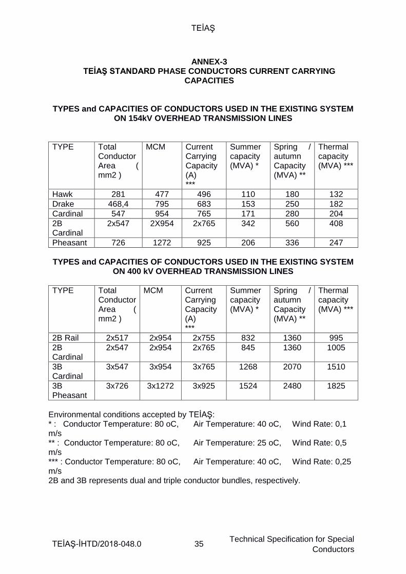
TEİAŞ
TEİAŞ-İHTD/2018-048.0 35 Technical Specification for Special
Conductors
ANNEX-3
TEİAŞ STANDARD PHASE CONDUCTORS CURRENT CARRYING CAPACITIES
TYPES and CAPACITIES OF CONDUCTORS USED IN THE EXISTING SYSTEM
ON 154kV OVERHEAD TRANSMISSION LINES
TYPE Total Conductor Area ( mm2 )
MCM Current Carrying Capacity (A) ***
Summer capacity (MVA) *
Spring / autumn Capacity (MVA) **
Thermal capacity (MVA) ***
Hawk 281 477 496 110 180 132
Drake 468,4 795 683 153 250 182
Cardinal 547 954 765 171 280 204
2B Cardinal
2x547 2X954 2x765 342 560 408
Pheasant 726 1272 925 206 336 247
TYPES and CAPACITIES OF CONDUCTORS USED IN THE EXISTING SYSTEM
ON 400 kV OVERHEAD TRANSMISSION LINES
TYPE Total Conductor Area ( mm2 )
MCM Current Carrying Capacity (A) ***
Summer capacity (MVA) *
Spring / autumn Capacity (MVA) **
Thermal capacity (MVA) ***
2B Rail 2x517 2x954 2x755 832 1360 995
2B Cardinal
2x547 2x954 2x765 845 1360 1005
3B Cardinal
3x547 3x954 3x765 1268 2070 1510
3B Pheasant
3x726 3x1272 3x925 1524 2480 1825
Environmental conditions accepted by TEİAŞ: * : Conductor Temperature: 80 oC, Air Temperature: 40 oC, Wind Rate: 0,1 m/s ** : Conductor Temperature: 80 oC, Air Temperature: 25 oC, Wind Rate: 0,5 m/s *** : Conductor Temperature: 80 oC, Air Temperature: 40 oC, Wind Rate: 0,25 m/s 2B and 3B represents dual and triple conductor bundles, respectively.

TEİAŞ
TEİAŞ-İHTD/2018-048.0 36 Technical Specification for Special
Conductors
ANNEX-4 A
TYPE TESTS APPLICABLE ON THE CONDUCTOR AND CONDUCTIVE MATERIAL
Test Name
Bütün İletken
(TS EN
50182 &
50540 &
60889) Full
Conductor
Çinko Kaplı Çelik Teller Wires (TS EN
50189) Zinc
Coated Steel
Alüminyum and
Alüminyum Alaşımlı Teller
(TS EN 60889 & 50183 &
İEC 62004) Aluminium
& Aluminium Alloy Wires
Alüminy
um Kaplı Çelik and Çelik
Alaşım Teller (IEC
61232) Aluminium Clad
Steel Wires
Kompozit Öz Teli (ASTM B
987 & EN 50540)
Composite
Wires/Strands
Madd
e Numarası
Claus
e Numb
er
Yüzey durumu (Surface Condition)
X X X X X 3.1.1 & 3.2.1
Çap (Diameter)
X X X X X 3.1.2 & 3.2.2
Kesit alanı (Cross-section)
X X X X X
D.C. Direnç (Conductor DC
Electrical Resistance)
X - - - - 3.1.3 IEC 60468
Hareketsizlik (Inertness)
X - - - - 3.1.4
Adım Oranı and Adım Yönü
(Lay Ratio & Direction of Lay)
X - - - - 3.1.5
Tellerin Tipi and Sayısı (Number &
Type of Wires)
X - - - - 3.1.6
Birim Ağırlığı (Mass Per Unit
Length)
X - - - - 3.1.7
(Gerilme Uzama Eğrisi)
Stress – Strain Curve
X - - - - 3.1.8
Çekme Kopma Mukavemeti
(Tensile Breaking Strength)
X - - - - 3.1.9

TEİAŞ
TEİAŞ-İHTD/2018-048.0 37 Technical Specification for Special
Conductors
Çekme Testi (Stringing Test)
X* - - - - 3.1.10
Yüzey Emisyonu (Surface Emissivity)
X - - - - 3.1.11
Creep Testi X EN 61395
A.C. Direnç (AC Electrical
Resistance)
X* - - - -
Kopma Mukavemeti (Tensile Strength)
X X X X 3.2.3.1
Uzama Testi (Elongation Test)
- X X X X 3.2.3.2
% 1 Uzama Testinde Stres (Stress at 1%
Extension Test)
- X - X - 3.2.3.3
Özdirenç Resistivity
- - X X - 3.2.4
Sarma testi (Wrapping Test)
- X X X - 3.2.5
Kaynak Welding
- - X - - 3.2.6
Çinko kütlesi (Mass of Zinc)
- X - - - 3.2.7.1
Çinko Daldırma Testi
(Zinc Dip Test)
- X - - - 3.2.7.2
Çinko Kaplama Yapışma
Adhesion of Zinc Coating
- X - - - 3.2.7.3
Alüminyum Kaplama Kalınlığı and Düzgünlüğü
Cladding Uniformity and
Thickness
-
-
-
X
- 3.2.8
Burulma testi Torsion Test
- X X X - 3.2.9
Corona Sönüm Gerilim Testi
(Corona extinction Voltage Test) (dry)
X* 3.2.11
Radyo frekans testi Radio (İnterference Voltage Test )(dry)
X* 3.2.12
Yüksek Sıcaklık Dayanımı and
Akma Testi (High Temperature
X* 3.2.13

TEİAŞ
TEİAŞ-İHTD/2018-048.0 38 Technical Specification for Special
Conductors
endurance & Creep Test on Stranded
Conductor)
Kasnak Testi (Sheaves Test)
X* 3.2.14
Eksenel Darbe Testi (Axial Impact Test)
X* 3.2.15
Radyal Ezilme Testi (Radial Crush Test)
X* 3.2.16
Rüzgar Titreşim Testi
(Aeolian Vibration Test)
X* 3.2.17
Burulma Sünekliliği Testi (Torsional
Ductility Test)
X* 3.2.18
Sıcaklık Döngüsü Testi (Temperature
Cycle Test)
X 3.2.19
Alüminyum Alaşımlı Tellerde Isı Direnci
Testi (Heat Resistance
Test On Aluminium Alloy Strands or
Core)
X* 3.2.20
Alüminyum kaplı öz telinde bükme testi
(Bending test on Aluminium clad core
wire) (Uygulanabiliyorsa)
X* 3.2.21
Alüminyum kaplı tellerde sıkıştırma
testi (Compression test on Aluminium
clad core) (Uygulanabiliyorsa)
X* 3.2.22
Öz teli / öz telleri için doğrusal
genleşme katsayısı Coefficient of linear expansion for core/
core wires
X* X* X* 3.2.23
Kırılganlık Testi (Strand Brittle
fracture test-for composite core
only)
X 3.2.24
Camsı geçiş sıcaklığı
- - - - X

TEİAŞ
TEİAŞ-İHTD/2018-048.0 39 Technical Specification for Special
Conductors
(Glass Transition Temperature)
Yoğunluk (Density)
- - - - X
Isı/Gerilme testi (Heat/Stress Test)
- - - - X
Isıya Maruz Kalma Testi
(Heat Exposure Test)
- - - - X
Bükme testi (Bending Test)
- - - - X
Büküm sonrası boya sızma, çatlak
testi (Dye Penetrant after Bending Test)
- - - - X 3.2.10
Büküm sonrası çekme dayanımı
testi (Tensile Test after Bending Test)
- - - - X
Galvanik koruma kalınlık testi
(Galvanic Protection Barrier Layer
Thickness Test)
- - - - X
* The DIRECTORATE may request the performance of these tests depending on the special conductor type, place of use, voltage level and submitted documents.

TEİAŞ
TEİAŞ-İHTD/2018-048.0 40 Technical Specification for Special
Conductors
ANNEX- 4 B SAMPLE TESTS APPLICABLE ON THE CONDUCTOR and CONDUCTIVE
MATERIAL
Test Name
Bütün İletken (TS EN 50182 &
EN 50540)
Full Conduct
or
Çinko Kaplı Çelik Teller Wires
(TS EN 50189)
Zinc Coated Steel
Alüminyum and
Alüminyum Alaşımlı Teller
(TS EN 60889 & 50183 &
İEC 62004) Aluminium
& Aluminium Alloy Wires
Alüminy
um Kaplı Çelik Teller (IEC
61232) Aluminium Clad
Steel Wires
Kompozi
t Öz Teli (ASTM
B 987 & EN
50540) Compos
ite Wires/Str
ands
Madde
Numarası
Clause
Number
Yüzey durumu (Surface Condition)
X X X X X 3.1.1 & 3.2.1
Çap (Diameter)
X X X X X 3.1.2 & 3.2.2
Kesit alanı (Cross-section)
X X X X X
D.C. Direnç (Conductor DC
Electrical Resistance)
X - - - - 3.1.3 IEC 60468
Hareketsizlik (Inertness)
X - - - - 3.1.4
Sarım Oranı and Sarım Yönü (Lay
Ratio & Direction of Lay)
X - - - - 3.1.5
Tel Sayısı and Türü (Number & Type of
Wires)
X - - - - 3.1.6
Birim Ağırlığı (Mass Unit Length)
X - - - - 3.1.7
Yüzey Emisyonu (Surface Emissivity)
X - - - - 3.1.11
Kopma Mukavemeti (Tensile Strength)
X X X X X 3.2.3.1
Uzama Testi (Elongation Test)
- X X X X 3.2.3.2
% 1 Uzatma Testinde Stres (Stress at 1%
Extension Test)
- X - X - 3.2.3.3
Özdirenç - - X X - 3.2.4
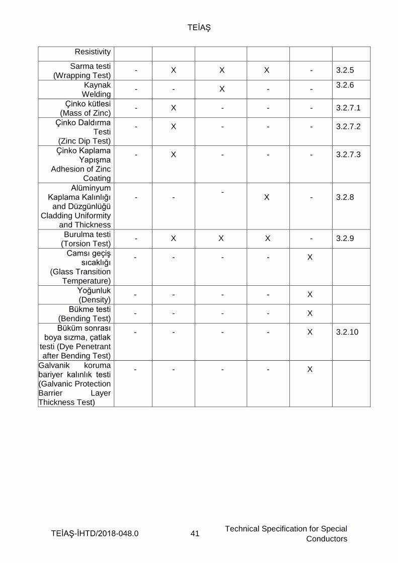
TEİAŞ
TEİAŞ-İHTD/2018-048.0 41 Technical Specification for Special
Conductors
Resistivity
Sarma testi (Wrapping Test)
- X X X - 3.2.5
Kaynak Welding
- - X - - 3.2.6
Çinko kütlesi (Mass of Zinc)
- X - - - 3.2.7.1
Çinko Daldırma Testi
(Zinc Dip Test)
- X - - - 3.2.7.2
Çinko Kaplama Yapışma
Adhesion of Zinc Coating
- X - - - 3.2.7.3
Alüminyum Kaplama Kalınlığı and Düzgünlüğü
Cladding Uniformity and Thickness
-
-
-
X
- 3.2.8
Burulma testi (Torsion Test)
- X X X - 3.2.9
Camsı geçiş sıcaklığı
(Glass Transition Temperature)
- - - - X
Yoğunluk (Density)
- - - - X
Bükme testi (Bending Test)
- - - - X
Büküm sonrası boya sızma, çatlak
testi (Dye Penetrant after Bending Test)
- - - - X 3.2.10
Galvanik koruma bariyer kalınlık testi (Galvanic Protection Barrier Layer Thickness Test)
- - - - X

TEİAŞ
TEİAŞ-İHTD/2018-048.0 42 Technical Specification for Special
Conductors
ANNEX-5 Minimum Tensile Strengths, Elongation and Stress at 1% Values
Material
Bireysel Tel Çapı
Individual Wire
Diameter (mm)
Minimum Tel Çekme Dayanımı
Minimum Wire
Tensile Strength
(MPa)
Minimum
uzama
Minimum
Elongation (%)
% 1 uzamada
stres
Stress at 1%
Extension (N/mm2)
Galvanised Steel Galvanizli çelik
2.75 – 3.00
3.00 – 3.50
1350
1300
3.5
1140
1100
Aluminium Clad Steel
Alüminyum Kaplı Çelik
1.25 – 3.25 1340 1.0 1200
High Strength Galvanised Steel (Matthew Conductor Only)
Yüksek mukavemetli galvanizli çelik
3.00 – 3.50
1750
4.5
1311
Aluminium
2.50 – 3.00 170.0 - -
3.00 – 3.50 165.0 - -
3.50 – 5.00 160.0 - -
Aluminium Alloy
Alüminyum alaşımı
1.50 – 5.00 295 3.5 -
The international standards and the approved conductor data to be provided by the Contractor shall be referred to for the values that are not indicated herein.

TEİAŞ
TEİAŞ-İHTD/2018-048.0 43 Technical Specification for Special
Conductors
ANNEX-6 LIST OF MATERIALS OrderNo : ............
Dwg No : .............
1 2 3 4
1) Conductor type :
2) Diameter of the complete conductor (mm) :
3) Cross Section area :
- Total cross section area of aluminum (mm2) :
- Total cross section area of conductor core (mm2) :
- Total cross section area of the conductor (mm2) :
4) Number of wires on the conductor layers :
(aluminum wire number / conductor core wire number)
5) Unit weight of the conductor (kg/km) :
6) Maximum system voltage at which the conductor
Will be used (kV rms) :
7) Rated frequency (Hz) :
8) Rated breaking force (kN) :
9) Final elasticity modulus of the conductor (kg/mm2) :
10) Thermal elongation coefficient of the conductor (1/0Cx10-6) :
11) Current carrying capacities of complete conductor (A) :
(Under the conditions indicated in Annex 3)
12) Distance and sag values of the complete conductor (m) :
(under the conditions indicated in Annex 1)
13) Operational Conditions (shall be determined by the DIRECTORATE)
- Height from sea level (m) :
- Ambient temperature (C)
- Maximum :
- Minimum :
- 24-hour average :
- Annual average :
Wind pressure (kg/m2) :
Maximum solar radiation (W/m2) :
13) Material code number of the purchaser :
14) Number of years of protection to be considered in
The production of reels
15) Number of reels (piece) :

TEİAŞ
TEİAŞ-İHTD/2018-048.0 44 Technical Specification for Special
Conductors
ANNEX-7 LIST OF WARRANTED CHARACTERISTICS – TECHNICAL PARAMETERS
Order No
Dwg No
Mtr. Code No of Purchaser
Article Definition Unit
(Metric)
Requested value
Warranted value
1 Manufacturer Firm
2 Type of conductor
3 Name of conductor
4 Operational conditions
Elevation from sea level m
Ambient temperature
Maximum C
Minimum C
24 –hour average
C
Annual average C
Wind pressure kg/m2
Maximum solar radiation W/m2
5 Number of layers and Number of wires in layers
Aluminum layer Adet
Conductor core layer
Adet
6 Diameter Entire conductor
mm
Aluminum wire mm
Conductor core mm
7 Cross section area Entire conductor mm2
Aluminum wire mm2
Conductor core mm2
8 Unit weight
Entire conductor kg/km
Aluminum wire kg/km
Conductor core kg/km
9 Rated (Maximum) Breaking force
Entire conductor kN
Conductor core kN
10 Maximum Conductor Temperature
Continuous operation
C
Short period (emergency)
C
11 Type and Thickness of Zinc Coating mm
12 Type and thickness of aluminum coating (if any)
mm
Elasticity modulus of the conductor
Primitive Elasticity modulus of the conduc.
kg/mm2
Final elasticity modulus of the conductor
kg/mm2
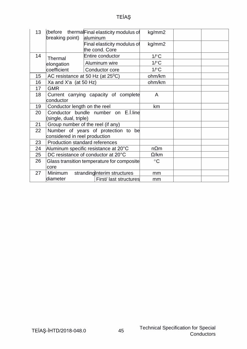
TEİAŞ
TEİAŞ-İHTD/2018-048.0 45 Technical Specification for Special
Conductors
13 (before thermal breaking point)
Final elasticity modulus of aluminum
kg/mm2
Final elasticity modulus of the cond. Core
kg/mm2
14 Thermal elongation coefficient
Entire conductor 1/C
Aluminum wire 1/C
Conductor core 1/C
15 AC resistance at 50 Hz (at 250C) ohm/km
16 Xa and X'a (at 50 Hz) ohm/km
17 GMR
18 Current carrying capacity of complete conductor
A
19 Conductor length on the reel km
20 Conductor bundle number on E.İ.line (single, dual, triple)
21 Group number of the reel (if any)
22 Number of years of protection to be considered in reel production
23 Production standard references
24 Aluminum specific resistance at 20°C nΩm
25 DC resistance of conductor at 20°C Ω/km
26 Glass transition temperature for composite core
C
27 Minimum stranding diameter
Interim structures mm
First/ last structures mm

TEİAŞ
TEİAŞ-İHTD/2018-048.0 46 Technical Specification for Special
Conductors
ANNEX-8 LIST OF DEVIATIONS
Order No.: ................ Dwg.No. : ................
Mtr. code no of Purchaser: ................ A- DEVIATIONS FROM TECHNICAL SPECIFICATIONS (The articles containing deviations and what those deviations are shall be clearly indicated by the bidder.) - ………………………………………………………………. - …………………………………………………………………. - …………………………………………………………………. -………………………………………………………………….. - …………………………………………………………………. -………………………………………………………………….. -……………………………………………………………………. B- DEVIATIONS IN THE LIST OF WARRANTED CHARACTERISTICS (The articles containing deviations and what those deviations are shall be clearly indicated by the bidder.) - ………………………………………………………………. - …………………………………………………………………. - …………………………………………………………………. -…………………………………………………………………..

TEİAŞ
TEİAŞ-İHTD/2018-048.0 47 Technical Specification for Special
Conductors
ANNEX-9 CONDUCTOR SECTION DRAWING
(CONDUCTOR SECTION DRAWING)
CONDUCTOR NAME
*This section drawing is representative. If found necessary, additional information can be added.
FIRM NAME AND LOGO
COMPANY NAME
CONDUCTOR NAME
SPECIFIC CONDUCTOR DIAMETER
SPECIFIC SECTION AREA OF CONDUCTOR
ALUMINUM SECTION AREA
TOTAL DIAMETER OF THE CONDUCTOR
TOTAL SECTION OF THE CONDUCTOR
NUMBER OF LAYERS: LAYER 1 WIRE NUMBER LAYER 2 WIRE NUMBER
DRAWN BY
APPROVED BY
DRAWING NUMBER