Embed Size (px)
Citation preview
VOL-II (TS) E22-AIR CONDITIONER- Page 1 of 3
ODISHA POWER TRANSMISSION CORPORATION
LIMITED OFFICE OF THE SR. GENERAL MANAGER,
CENTRAL PROCUREMENT CELL,
JANPATH, BHUBANESWAR – 751022
TECHNICAL SPECIFICATION
FOR
SPLIT TYPE INDIVIDUAL UNIT
AIR CONDITIONER
VOL-II (TS) E22-AIR CONDITIONER- Page 2 of 3
TECHNICAL SPECIFICATION FOR AIR
CONDITIONING SYSTEM
1.0 GENERAL The specification covers supply, installation, testing and commissioning and handing over of Air conditioning system for the control room building The AC units for control room building shall be set to maintain the following inside conditions. DBT 24.4 Deg C ± 2 Deg C 1.1 The following room shall be air conditioned a) Control Room b) Conference room c) Testing lab 1.2 Air conditioning requirement of rooms indicated shall be met by using split AC units. High wall type split AC units of required capacity as per design (to be submitted for approval) with high wall type indoor evaporator unit shall be used. In case the area is more than ductable split AC units may also be designed for better effect. 1.3 The exact quantity of the split AC units shall be designed taking the room area and the same may be proposed for necessary approval. However 2 TR capacity split AC units of 5 star rating to be considered. The quantity shall be approximately as mentioned below. PROPOSED NO OF A.C UNITS SHALL BE OF 5 STAR RATING: 1) FOR ALL 220/132/33 KV S/S CONTROL ROOM AREA
A) 20 NOS 2 TR CAPACITY. B) 220/33 KV S/S:15 NOS 2 TR CAPACITY.
2) FOR ALL 132/33 KV SUB-STATION: 15 NOS 2 TR CAPACITY. 3) FOR 400/220 KV S/S CONTROL ROOM: 30 NOS 2 TR CAPACITY 1.4 Copper refrigerant piping complete with insulation between the indoor and remote outdoor condensers as required. 1.5 SCOPE: The scope of the equipment to be furnished and services to be provided under the contract are outlined herein and the same is to be read in conjunction with the provision contained. The scope shall be deemed to include all such items which although not specifically mentioned in the bid documents and/or in bidders proposal, but are required to make the equipment/system complete for its safe, efficient, reliable and trouble free operation. Unit should be hermetically sealed 1.7 PVC drains piping from the indoor units up to the nearest drain point to be done. 1.8 Power and control cables between the indoor unit and outdoor unit and earthing 1.9 GI brackets for for outdoor condensing unit and proper earthing. 1.10 Specification for Split AC units.
VOL-II (TS) E22-AIR CONDITIONER- Page 3 of 3
The split AC units will be complete with indoor evaporator unit, outdoor condensing units and cordless remote control units. Out door units shall comprise of hermetically sealed reciprocating/rotary compressors mounted on vibration isolators, propeller type axial flow fans and copper tube aluminium finned coils assembled in a sheet metal. The casing and the total unit shall be properly treated and shall be weather proof type. They shall be compact in size and shall have horizontal discharge of air. The indoor unit shall be high wall type. The indoor unit shall be compact and shall have elegant appearance. They shall have low noise centrifugal blowers driven by special motors and copper tube aluminium finned cooling coils. Removable and washable polypropylene filters shall be provided. They shall be complete with multifunction cordless remote control unit with special features like programmable timer, sleep mode and softy dry mode etc. The split AC units shall be of Carrier/Blue Star/Hitachi/Voltas/Samsung/LG make. The air conditioner unit should be provided with a required voltage stabilizer (from 90 V to 275 V AC).
VOL-II (TS) E23-CONTROL, POWER,COAXIAL CABLE- Page 1of 25
ODISHA POWER TRANSMISSION CORPORATION LIMITED
TECHNICAL SPECIFICATION
FOR
1-COAXIALCABLES
2-CONTROL & POWER CABLES
VOL-II (TS) E23-CONTROL, POWER,COAXIAL CABLE- Page 2of 25
TECHNICAL SPECIFICATION
ITEM- H.F. CO-AXIAL CABLE, CONTROL CABLE & TELEPHONE CABLE
SCOPE
The specification covers the design, manufacture, testing before dispatch and setting to service of
the following cables for their utility in power line carrier communication system in OPTCL.
1. H.F. Co-axial cable
2. Control cable
3. Telephone cable
4. H.F. Co-axial cable
General:
(a) The H.F.C0-axial cable shall be offered to connect the coupling unit (Line Matching under
Symmetrical LMU) with PLC terminals. This serves maximum transfer of power between the
carrier equipment to HT lines with minimum losses. The cable is also used for interconnection
between two line matching units.
(b) The high frequency cable to be offered shall be suitable for being laid in the ground or in
trenches or in ducts. It shall be duly armoured and confirm IS:5802 of 1978.
(c) The center core of the cable shall consists of tinned or enameled higfh purity copper
conductor which has to be insulated by polythene sheath and shall be screened by tinned copper
braidings. This braiding shall be sheathed by a PVC cover and GI wire enamoured and overall PVC
sheathed and shall be suitable for tropical use. The six, type and quality of insulation shall be stated
in the tender.
(d) The capacitance of the co-axial cable shall be low as to minimize attenuation at the carrier
frequency range.
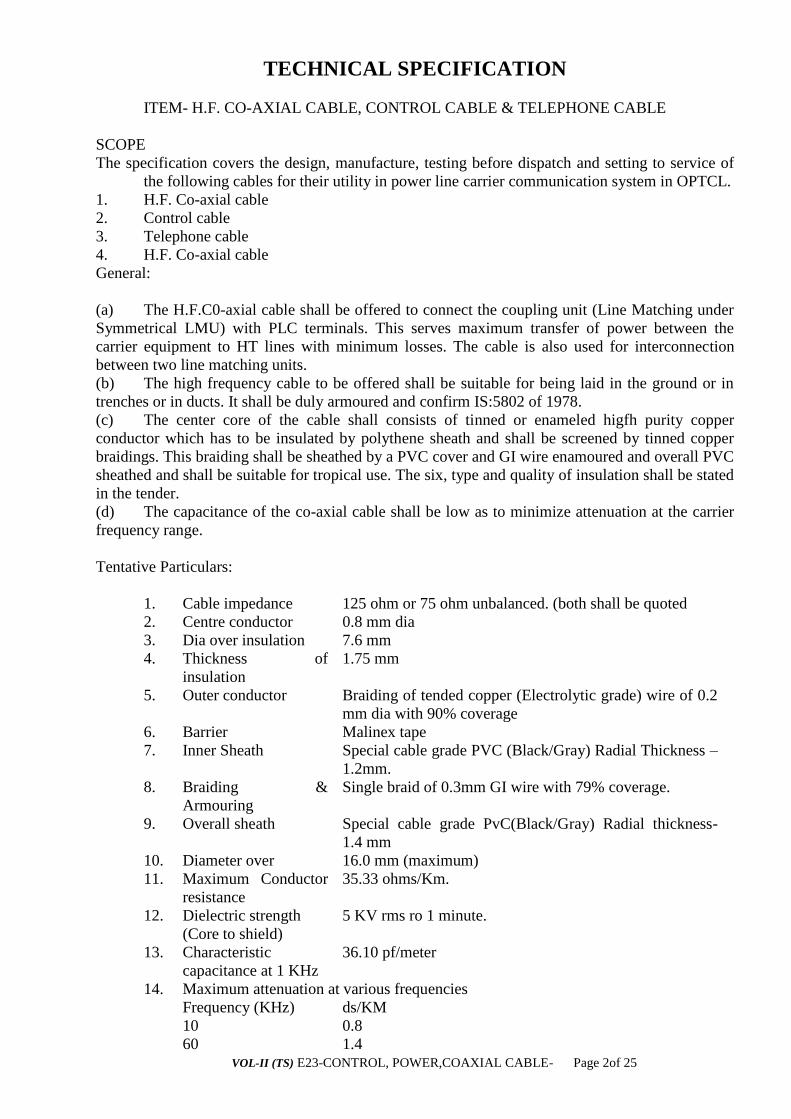
Tentative Particulars:
1. Cable impedance 125 ohm or 75 ohm unbalanced. (both shall be quoted
2. Centre conductor 0.8 mm dia
3. Dia over insulation 7.6 mm
4. Thickness of
insulation
1.75 mm
5. Outer conductor Braiding of tended copper (Electrolytic grade) wire of 0.2
mm dia with 90% coverage
6. Barrier Malinex tape
7. Inner Sheath Special cable grade PVC (Black/Gray) Radial Thickness –
1.2mm.
8. Braiding &
Armouring
Single braid of 0.3mm GI wire with 79% coverage.
9. Overall sheath Special cable grade PvC(Black/Gray) Radial thickness-
1.4 mm
10. Diameter over 16.0 mm (maximum)
11. Maximum Conductor
resistance
35.33 ohms/Km.
12. Dielectric strength
(Core to shield)
5 KV rms ro 1 minute.
13. Characteristic
capacitance at 1 KHz
36.10 pf/meter
14. Maximum attenuation at various frequencies
Frequency (KHz) ds/KM
10 0.8
60 1.4

VOL-II (TS) E23-CONTROL, POWER,COAXIAL CABLE- Page 3of 25
300 3.30
500 4.70
15.
Minimum bending
radios for installation
20 CM
16. Insulation resistance Meg. Ohm/Km(Min.)
2. Telephone Cable:
1) The telephone cables are of armoured or unarmoured type depending on the requirements.
The telephone cable shall have 0.5 or 0.6 mm annealed tinned copper conductor, PVC insulated,
cores colour coded, twisted into pairs, laid up, taped and overall PVC sheathed confirming to ITD
specification. In case of armoured cable, it must be GI wiser/strip armoured with inner and outer
sheathed confirming to IS: 1554 (Part-I)/1976.
2) The following cables may be quoted in the tender.
(1) 25 pair Armoured telephone cable
(2) 10 pair Armoured telephone cable
(3) 10 pair unarmoured telephone cable
(4) 5 pair unarmoured telephone cable.
3) The following cables may be quoted in the tender.
(1) 2.5 sq.mm twin core (solid)
(2) 10 sq.mm multistrand twin core.
4) tests – Type Test reports shall be furnished.
VOL-II (TS) E23-CONTROL, POWER,COAXIAL CABLE- Page 4of 25
TECHNICAL SPECIFICATION FOR
CONTROL AND POWER CABLES
PART 1 : SCOPE AND CONDITIONS
1. SCOPE
This specification covers the testing and performance requirements of power and control cables for
installation on the Distribution System to be established at the loaction as indicated against this tender.
The equipment offered shall have been successfully type tested and the design shall have been in
satisfactory operation for a period not less than two years on the date of bid opening. Compliance shall
be demonstrated by submitting with the bid, (i) authenticated copies of the type test reports and (ii)
performance certificates from the users..
The power and control cables shall conform in all respects to highest standards of engineering, design,
workmanship, this specification and the latest revisions of relevant standards at the time of offer and the
Project Manager shall have the power to reject any work or material, which, in his judgement, is not in
full accordance therewith.
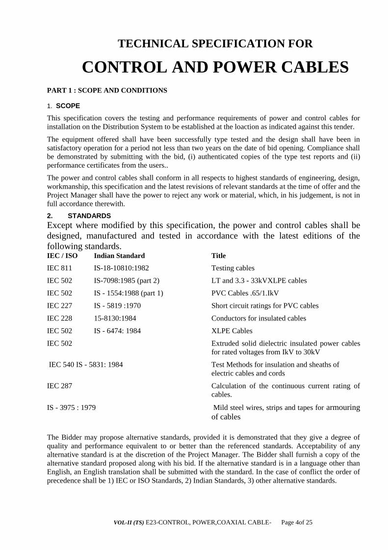
2. STANDARDS
Except where modified by this specification, the power and control cables shall be
designed, manufactured and tested in accordance with the latest editions of the
following standards. IEC / ISO Indian Standard Title
IEC 811 IS-18-10810:1982 Testing cables
IEC 502 IS-7098:1985 (part 2) LT and 3.3 - 33kVXLPE cables
IEC 502 IS - 1554:1988 (part 1) PVC Cables .65/1.IkV
IEC 227 IS - 5819 :1970 Short circuit ratings for PVC cables
IEC 228 15-8130:1984 Conductors for insulated cables
IEC 502 IS - 6474: 1984 XLPE Cables
IEC 502 Extruded solid dielectric insulated power cables
for rated voltages from IkV to 30kV
IEC 540 IS - 5831: 1984 Test Methods for insulation and sheaths of
electric cables and cords
IEC 287 Calculation of the continuous current rating of
cables.
IS - 3975 : 1979 Mild steel wires, strips and tapes for armouring
of cables
The Bidder may propose alternative standards, provided it is demonstrated that they give a degree of
quality and performance equivalent to or better than the referenced standards. Acceptability of any
alternative standard is at the discretion of the Project Manager. The Bidder shall furnish a copy of the
alternative standard proposed along with his bid. If the alternative standard is in a language other than
English, an English translation shall be submitted with the standard. In the case of conflict the order of
precedence shall be 1) IEC or ISO Standards, 2) Indian Standards, 3) other alternative standards.

VOL-II (TS) E23-CONTROL, POWER,COAXIAL CABLE- Page 5of 25
This list is not to be considered exhaustive and reference to a particular standard or
recommendation in this Specification does not relieve the Contractor of the necessity
of providing the goods complying with other relevant standards or recommendations. 3. SERVICE CONDITIONS
The service conditions shall be as follows:
• maximum altitude above sea level l1,000m
• maximum ambient air temperature 50°C
• maximum daily average ambient air temperature 35°C
minimum ambient air temperature o°C
maximum temperature attainable by an object exposed to the sun 60°C
maximum yearly weighted average ambient temperature 32°C
maximum relative humidity 100%
average number of thunderstorm days per annum (isokeraunic level) 70
average number of rainy days per annum 120
average annual rainfall 150cm
wind pressures as per IS 802 (Part I/ Sect.l) : 1995
Wind Zones (Orissa)
2
3
5
Terrain Category 1
57.4 kg/m2
73.1 kg/m
2
94.3kg/m
2
Terrain Category 2
49.3
62.6
80.9
Terrain Category 3
35.6
45.3
58.4
Light
Medium
Heavy
Environmentally, the region where the work will take place includes coastal areas, subject to high
relative humidity, which can give rise to condensation. Onshore winds will frequently be salt laden. On
occasions, the combination of salt and condensation may create pollution conditions for outdoor
insulators.
Therefore, outdoor material and equipment shall be designed and protected for use in
exposed, heavily polluted, salty, corrosive and humid coastal atmosphere.
4. SYSTEM CONDITIONS
The equipment shall be suitable for installation in supply systems of the following characteristics:
• Frequency 50Hz
• Nominal system voltages 33kV
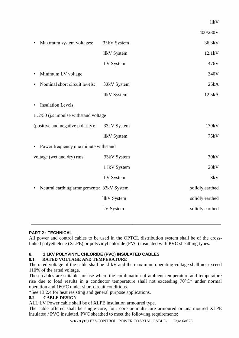
VOL-II (TS) E23-CONTROL, POWER,COAXIAL CABLE- Page 6of 25
llkV
400/230V
• Maximum system voltages: 33kV System 36.3kV
llkV System 12.1kV
LV System 476V
• Minimum LV voltage 340V
• Nominal short circuit levels: 33kV System 25kA
llkV System 12.5kA
• Insulation Levels:
1 .2/50 (j.s impulse withstand voltage
(positive and negative polarity): 33kV System 170kV
llkV System 75kV
• Power frequency one minute withstand
voltage (wet and dry) rms 33kV System 70kV
1 IkV System 28kV
LV System 3kV
• Neutral earthing arrangements: 33kV System solidly earthed
llkV System solidly earthed
LV System solidly earthed
PART 2 : TECHNICAL
All power and control cables to be used in the OPTCL distribution system shall be of the cross-
linked polyethelene (XLPE) or polyvinyl chloride (PVC) insulated with PVC sheathing types.
8. 1.1KV POLYVINYL CHLORIDE (PVC) INSULATED CABLES
8.1. RATED VOLTAGE AND TEMPERATURE
The rated voltage of the cable shall be l.l kV and the maximum operating voltage shall not exceed
110% of the rated voltage.
These cables are suitable for use where the combination of ambient temperature and temperature
rise due to load results in a conductor temperature shall not exceeding 70°C* under normal
operation and 160°C under short circuit conditions.
*See 13.2.4 for heat resisting and general purpose applications. 8.2. CABLE DESIGN
ALL LV Power cable shall be of XLPE insulation armoured type.
The cable offered shall be single-core, four core or multi-core armoured or unarmoured XLPE
insulated / PVC insulated, PVC sheathed to meet the following requirements:
VOL-II (TS) E23-CONTROL, POWER,COAXIAL CABLE- Page 7of 25
8.2.1. Conductor
• L.V System Cables (Power Cable XLPE insulated)
The conductor shall be of compacted round shape in single core cables and sector shaped in 3.5 or
4 core cables, made up from stranded aluminum wires complying with IS -8130:1984 / IEC 228.
The Cable shall be of XLPE insulated with armoured.
Cables with reduced neutral conductors shall comply with the cross-sections shown in the table
below.
• Control and Panel Wiring Cables (PVC insulated)
The conductor shall be of round stranded plain copper wires complying with IS - 8130:1984/IEC
228.
The conductors shall be of Flexibility Class 2 as per IS - 8130 : 1984.
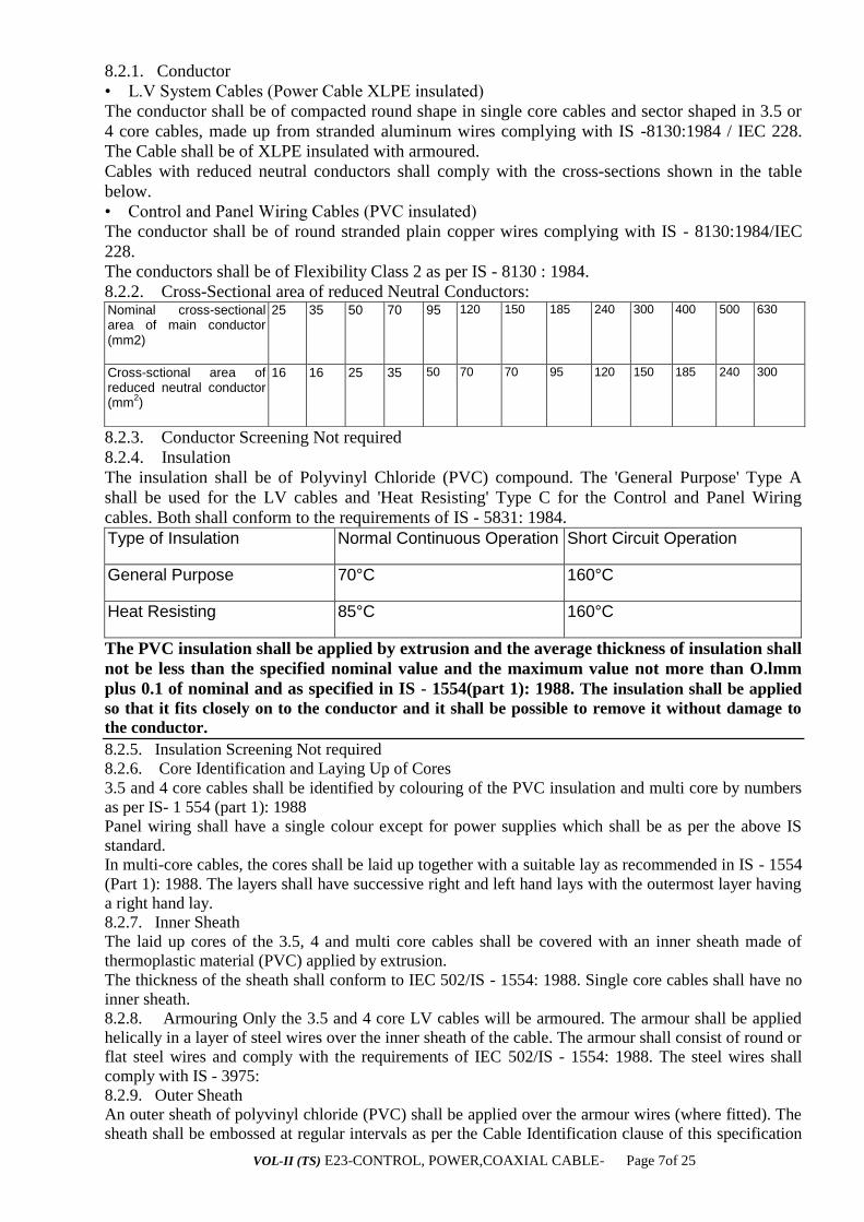
8.2.2. Cross-Sectional area of reduced Neutral Conductors: Nominal cross-sectional area of main conductor (mm2)
25
35
50
70
95
120
150
185
240
300
400
500
630
Cross-sctional area of reduced neutral conductor (mm
2)
16
16
25
35
50
70
70
95
120
150
185
240
300
8.2.3. Conductor Screening Not required
8.2.4. Insulation
The insulation shall be of Polyvinyl Chloride (PVC) compound. The 'General Purpose' Type A
shall be used for the LV cables and 'Heat Resisting' Type C for the Control and Panel Wiring
cables. Both shall conform to the requirements of IS - 5831: 1984.
Type of Insulation
Normal Continuous Operation
Short Circuit Operation
General Purpose
70°C
160°C
Heat Resisting
85°C
160°C
The PVC insulation shall be applied by extrusion and the average thickness of insulation shall
not be less than the specified nominal value and the maximum value not more than O.lmm
plus 0.1 of nominal and as specified in IS - 1554(part 1): 1988. The insulation shall be applied
so that it fits closely on to the conductor and it shall be possible to remove it without damage to
the conductor.
8.2.5. Insulation Screening Not required
8.2.6. Core Identification and Laying Up of Cores
3.5 and 4 core cables shall be identified by colouring of the PVC insulation and multi core by numbers
as per IS- 1 554 (part 1): 1988
Panel wiring shall have a single colour except for power supplies which shall be as per the above IS
standard.
In multi-core cables, the cores shall be laid up together with a suitable lay as recommended in IS - 1554
(Part 1): 1988. The layers shall have successive right and left hand lays with the outermost layer having
a right hand lay.
8.2.7. Inner Sheath
The laid up cores of the 3.5, 4 and multi core cables shall be covered with an inner sheath made of
thermoplastic material (PVC) applied by extrusion.
The thickness of the sheath shall conform to IEC 502/IS - 1554: 1988. Single core cables shall have no
inner sheath.
8.2.8. Armouring Only the 3.5 and 4 core LV cables will be armoured. The armour shall be applied
helically in a layer of steel wires over the inner sheath of the cable. The armour shall consist of round or
flat steel wires and comply with the requirements of IEC 502/IS - 1554: 1988. The steel wires shall
comply with IS - 3975:
8.2.9. Outer Sheath
An outer sheath of polyvinyl chloride (PVC) shall be applied over the armour wires (where fitted). The
sheath shall be embossed at regular intervals as per the Cable Identification clause of this specification
VOL-II (TS) E23-CONTROL, POWER,COAXIAL CABLE- Page 8of 25
and the minimum thickness and properties shall comply with the requirements of IEC 502/IS - 1554:
1988. The outer sheath for cables with general purpose insulation shall be of the type ST1 PVC
compound and for cables with heat resisting insulation type ST2 PVC compound conforming to the
requirements of IEC 502/IS - 5831: 1984.
The outer serving shall incorporate an effective anti-termite barrier and shall be capable of withstanding
a l0kV DC test voltage for five minutes after installation and annually thereafter.
Cables shall be installed as a single four core cable or three single phase cables plus neutral in a close
trefoil formation.
Current ratings shall be calculated in accordance with IEC 287 "Calculation of the continuous current
rating of cables with 100% load factor".
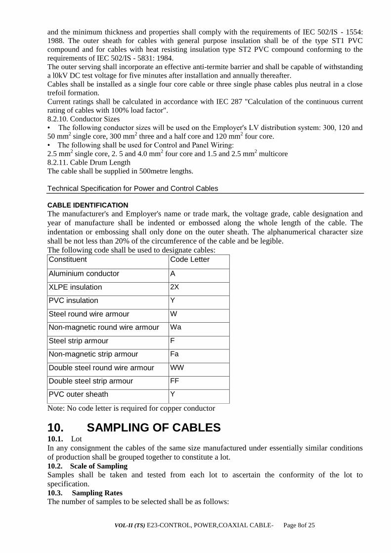
8.2.10. Conductor Sizes
• The following conductor sizes will be used on the Employer's LV distribution system: 300, 120 and
50 mm2 single core, 300 mm2 three and a half core and 120 mm2 four core.
• The following shall be used for Control and Panel Wiring:
2.5 mm2 single core, 2. 5 and 4.0 mm2 four core and 1.5 and 2.5 mm2 multicore
8.2.11. Cable Drum Length
The cable shall be supplied in 500metre lengths.
Technical Specification for Power and Control Cables
CABLE IDENTIFICATION
The manufacturer's and Employer's name or trade mark, the voltage grade, cable designation and
year of manufacture shall be indented or embossed along the whole length of the cable. The
indentation or embossing shall only done on the outer sheath. The alphanumerical character size
shall be not less than 20% of the circumference of the cable and be legible.
The following code shall be used to designate cables:
Constituent Code Letter
Aluminium conductor A
XLPE insulation 2X
PVC insulation Y
Steel round wire armour W
Non-magnetic round wire armour Wa
Steel strip armour F
Non-magnetic strip armour Fa
Double steel round wire armour WW
Double steel strip armour FF
PVC outer sheath Y
Note: No code letter is required for copper conductor
10. SAMPLING OF CABLES 10.1. Lot
In any consignment the cables of the same size manufactured under essentially similar conditions
of production shall be grouped together to constitute a lot.
10.2. Scale of Sampling
Samples shall be taken and tested from each lot to ascertain the conformity of the lot to
specification.
10.3. Sampling Rates
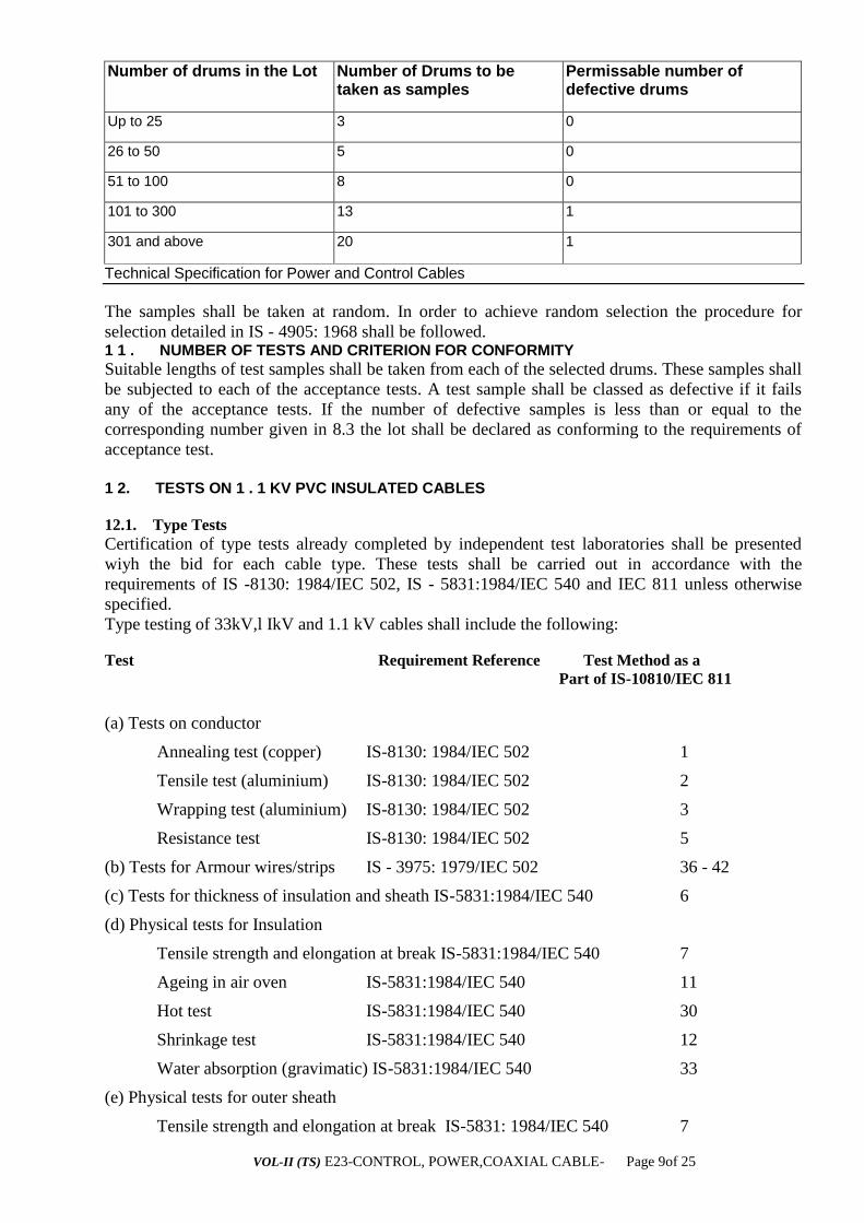
The number of samples to be selected shall be as follows:
VOL-II (TS) E23-CONTROL, POWER,COAXIAL CABLE- Page 9of 25
Number of drums in the Lot Number of Drums to be taken as samples
Permissable number of defective drums
Up to 25 3 0
26 to 50 5 0
51 to 100 8 0
101 to 300 13 1
301 and above 20 1
Technical Specification for Power and Control Cables
The samples shall be taken at random. In order to achieve random selection the procedure for
selection detailed in IS - 4905: 1968 shall be followed. 1 1 . NUMBER OF TESTS AND CRITERION FOR CONFORMITY
Suitable lengths of test samples shall be taken from each of the selected drums. These samples shall
be subjected to each of the acceptance tests. A test sample shall be classed as defective if it fails
any of the acceptance tests. If the number of defective samples is less than or equal to the
corresponding number given in 8.3 the lot shall be declared as conforming to the requirements of
acceptance test.
1 2. TESTS ON 1 . 1 KV PVC INSULATED CABLES
12.1. Type Tests
Certification of type tests already completed by independent test laboratories shall be presented
wiyh the bid for each cable type. These tests shall be carried out in accordance with the
requirements of IS -8130: 1984/IEC 502, IS - 5831:1984/IEC 540 and IEC 811 unless otherwise
specified.
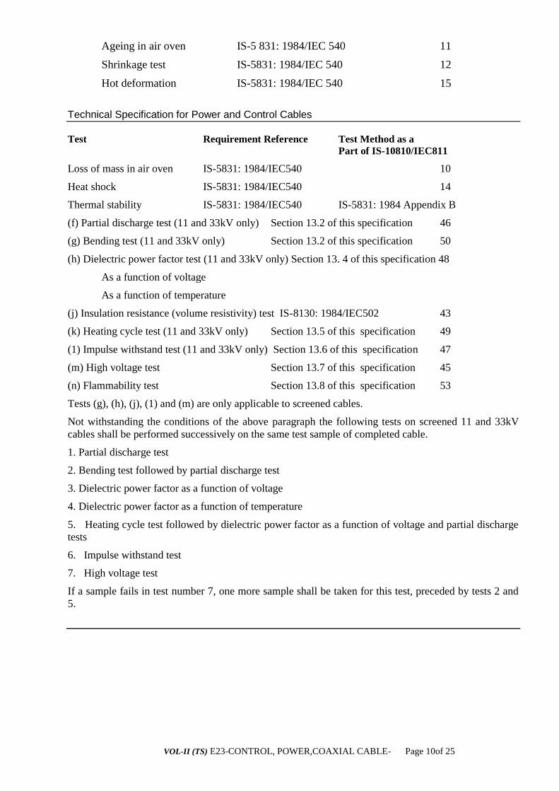
Type testing of 33kV,l IkV and 1.1 kV cables shall include the following:
Test Requirement Reference Test Method as a
Part of IS-10810/IEC 811
(a) Tests on conductor
Annealing test (copper) IS-8130: 1984/IEC 502 1
Tensile test (aluminium) IS-8130: 1984/IEC 502 2
Wrapping test (aluminium) IS-8130: 1984/IEC 502 3
Resistance test IS-8130: 1984/IEC 502 5
(b) Tests for Armour wires/strips IS - 3975: 1979/IEC 502 36 - 42
(c) Tests for thickness of insulation and sheath IS-5831:1984/IEC 540 6
(d) Physical tests for Insulation
Tensile strength and elongation at break IS-5831:1984/IEC 540 7
Ageing in air oven IS-5831:1984/IEC 540 11
Hot test IS-5831:1984/IEC 540 30
Shrinkage test IS-5831:1984/IEC 540 12
Water absorption (gravimatic) IS-5831:1984/IEC 540 33
(e) Physical tests for outer sheath
Tensile strength and elongation at break IS-5831: 1984/IEC 540 7
VOL-II (TS) E23-CONTROL, POWER,COAXIAL CABLE- Page 10of 25
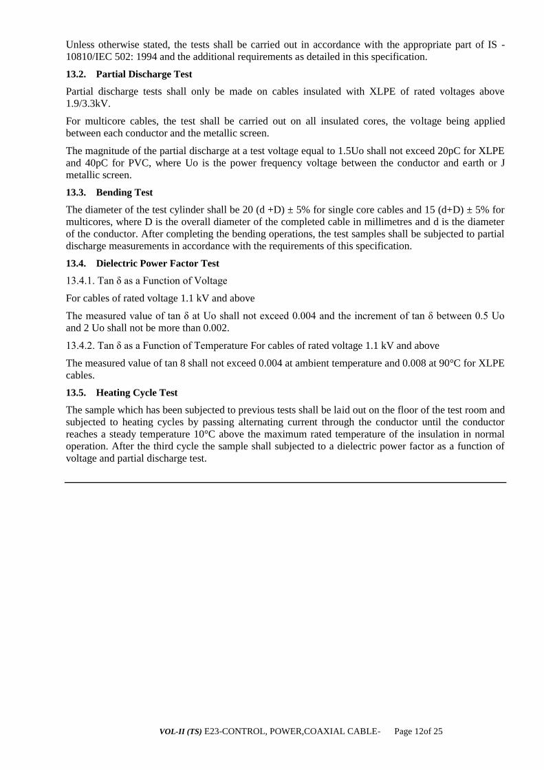
Ageing in air oven IS-5 831: 1984/IEC 540 11
Shrinkage test IS-5831: 1984/IEC 540 12
Hot deformation IS-5831: 1984/IEC 540 15
Technical Specification for Power and Control Cables
Test Requirement Reference Test Method as a
Part of IS-10810/IEC811
Loss of mass in air oven IS-5831: 1984/IEC540 10
Heat shock IS-5831: 1984/IEC540 14
Thermal stability IS-5831: 1984/IEC540 IS-5831: 1984 Appendix B
(f) Partial discharge test (11 and 33kV only) Section 13.2 of this specification 46
(g) Bending test (11 and 33kV only) Section 13.2 of this specification 50
(h) Dielectric power factor test (11 and 33kV only) Section 13. 4 of this specification 48
As a function of voltage
As a function of temperature
(j) Insulation resistance (volume resistivity) test IS-8130: 1984/IEC502 43
(k) Heating cycle test (11 and 33kV only) Section 13.5 of this specification 49
(1) Impulse withstand test (11 and 33kV only) Section 13.6 of this specification 47
(m) High voltage test Section 13.7 of this specification 45
(n) Flammability test Section 13.8 of this specification 53
Tests (g), (h), (j), (1) and (m) are only applicable to screened cables.
Not withstanding the conditions of the above paragraph the following tests on screened 11 and 33kV
cables shall be performed successively on the same test sample of completed cable.
1. Partial discharge test
2. Bending test followed by partial discharge test
3. Dielectric power factor as a function of voltage
4. Dielectric power factor as a function of temperature
5. Heating cycle test followed by dielectric power factor as a function of voltage and partial discharge
tests
6. Impulse withstand test
7. High voltage test
If a sample fails in test number 7, one more sample shall be taken for this test, preceded by tests 2 and
5.

VOL-II (TS) E23-CONTROL, POWER,COAXIAL CABLE- Page 11of 25
Technical Specification for Power and Control Cables
12.2. Acceptance Tests
The following shall constitute acceptance tests:
• Tensile test (aluminium)
• Annealing test (copper)
• Wrapping test
• Conductor resistance test
• Test for thickness of insulation and sheath
• Hot set test for insulation*
• Tensile strength and elongation at break test for insulation and outer sheath
• Partial discharge test (for screened cables only)**
• High voltage test
• Insulation resistance (volume resistivity) test.
• XLPE insulation only
** test to be completed on full drum of cable
12.3. Routine Tests
Routine tests shall be carried out on all of the cable on a particular order. These tests shall be carried out
in accordance with the requirements of IS - 8130: 1984/IEC 502 and IS - 5831:1984/IEC 540 unless
otherwise specified.
The following shall constitute routine tests.
• Conductor resistance test
• Partial discharge test (for 1 IkV and 33kV screened cables only)*
• High voltage test
* test to be completed on full drum of cable
12.4. Optional Test
Cold impact test for outer sheath (IS - 5831 - 1984), which shall be completed at the discretion of the
Project Manager and at the same time as test at low temperature for PVC as stipulated in the section on
special tests.
12.5. Special tests
Special tests shall be carried out at the Project Manager's discretion on a number of
cable samples selected by the Project Manager from the contract consignment. The
test shall be carried out on 10% of the production lengths of a production batch of the
same cable type, but at least one production length. Special tests shall be carried out
in accordance with the requirements of IEC 502 and IEC 540 unless otherwise
specified.
The following special tests shall be included:
• Conductor Examination (IEC-228)
• Check of Dimensions
• 4-Hour High Voltage Test for 11 kV and 33kV Cables only
• Hot set test for XLPE Insulation
• Test at low temperature for PVC
13. DETAILS OF TESTS
13.1. General
VOL-II (TS) E23-CONTROL, POWER,COAXIAL CABLE- Page 12of 25
Unless otherwise stated, the tests shall be carried out in accordance with the appropriate part of IS -
10810/IEC 502: 1994 and the additional requirements as detailed in this specification.
13.2. Partial Discharge Test
Partial discharge tests shall only be made on cables insulated with XLPE of rated voltages above
1.9/3.3kV.
For multicore cables, the test shall be carried out on all insulated cores, the voltage being applied
between each conductor and the metallic screen.
The magnitude of the partial discharge at a test voltage equal to 1.5Uo shall not exceed 20pC for XLPE
and 40pC for PVC, where Uo is the power frequency voltage between the conductor and earth or J
metallic screen.
13.3. Bending Test
The diameter of the test cylinder shall be 20 (d +D) ± 5% for single core cables and 15 (d+D) ± 5% for
multicores, where D is the overall diameter of the completed cable in millimetres and d is the diameter
of the conductor. After completing the bending operations, the test samples shall be subjected to partial
discharge measurements in accordance with the requirements of this specification.
13.4. Dielectric Power Factor Test
13.4.1. Tan δ as a Function of Voltage
For cables of rated voltage 1.1 kV and above
The measured value of tan δ at Uo shall not exceed 0.004 and the increment of tan δ between 0.5 Uo
and 2 Uo shall not be more than 0.002.
13.4.2. Tan δ as a Function of Temperature For cables of rated voltage 1.1 kV and above
The measured value of tan 8 shall not exceed 0.004 at ambient temperature and 0.008 at 90°C for XLPE
cables.
13.5. Heating Cycle Test
The sample which has been subjected to previous tests shall be laid out on the floor of the test room and
subjected to heating cycles by passing alternating current through the conductor until the conductor
reaches a steady temperature 10°C above the maximum rated temperature of the insulation in normal
operation. After the third cycle the sample shall subjected to a dielectric power factor as a function of
voltage and partial discharge test.
VOL-II (TS) E23-CONTROL, POWER,COAXIAL CABLE- Page 13of 25
Technical Specification for Power and Control Cables
13.7. High Voltage Test
13.7.1. Type/Acceptance Test
The cable shall withstand, without breakdown, at ambient temperature, an ac voltage equal to 3Uo,
when applied to the sample between the conductor and screen/armour (and between conductors in the
case of unscreened cable). The voltage shall be gradually increased to the specified value and
maintained for a period of 4 hours.
If while testing, interruption occurs during the 4 hour period the test shall be prolonged by the same
extent. If the interruption period exceeds 30 minutes the test shall be repeated.
13.7.2. Routine Test
Single core screened cables, shall withstand, without any failure, the test voltages given in this
specification for a period of five minutes between the conductor and metallic screen.
Single core unscreened cables shall be immersed in water at room temperature for one hour and the test
voltage then applied for 5 minutes between the conductor and water.
Multicore cables with individually screened cores, the test voltage shall be applied for 5 minutes
between each conductor and the metallic screen or covering.
Multicore cables without individually screened cores, the test voltage shall be applied for 5 minutes in
succession between each insulated conductor and all the other conductors and metallic coverings, if
any.
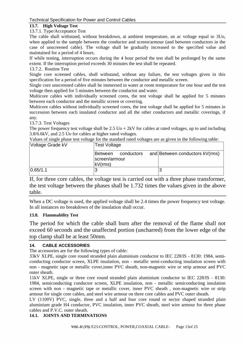
13.7.3. Test Voltages
The power frequency test voltage shall be 2.5 Uo + 2kV for cables at rated voltages, up to and including
3.8/6.6kV, and 2.5 Uo for cables at higher rated voltages.
Values of single phase test voltage for the standard rated voltages are as given in the following table:
Voltage Grade kV
Test Voltage
Between conductors and screen/armour kV(rms)
Between conductors kV(rms)
0.65/1.1 3 3
If, for three core cables, the voltage test is carried out with a three phase transformer,
the test voltage between the phases shall be 1.732 times the values given in the above
table.
When a DC voltage is used, the applied voltage shall be 2.4 times the power frequency test voltage.
In all instances no breakdown of the insulation shall occur.
13.8. Flammability Test
The period for which the cable shall burn after the removal of the flame shall not
exceed 60 seconds and the unaffected portion (uncharred) from the lower edge of the
top clamp shall be at least 50mm.
14. CABLE ACCESSORIES
The accessories are for the following types of cable:
33kV XLPE, single core round stranded plain aluminium conductor to IEC 228/IS - 8130: 1984, semi-
conducting conductor screen, XLPE insulation, non - metallic semi-conducting insulation screen with
non - magnetic tape or metallic cover,inner PVC sheath, non-magnetic wire or strip armour and PVC
outer sheath.
11kV XLPE, single or three core round stranded plain aluminium conductor to IEC 228/IS - 8130:
1984, semiconducting conductor screen, XLPE insulation, non - metallic semiconducting insulation
screen with non - magnetic tape or metallic cover, inner PVC sheath , non-magnetic wire or strip
armour for single core cables, and steel wire armour on three core cables and PVC outer sheath.
LV (1100V) PVC, single, three and a half and four core round or sector shaped stranded plain
aluminium grade H4 conductor, PVC insulation, inner PVC sheath, steel wire armour for three phase
cables and P.V.C. outer sheath. 14.1. JOINTS AND TERMINATIONS
VOL-II (TS) E23-CONTROL, POWER,COAXIAL CABLE- Page 14of 25
Joints and terminations shall be supplied in complete kit form with all materials and components
required to complete the installation. A complete set of instructions for the joint or termination shall
also be included in each kit.
Heat shrink pre-moulded joints and terminations shall be required for all XLPE and PVC cables and for
transition joints.
All components shall be capable of being stored without damage or deterioration at temperatures up to
50°C. The material expiry date shall be marked on all packages, where appropriate.
Details of all equipment, tools and protective clothing required to complete the joint or termination shall
be included with each joint or termination kit.
Components shall not be adversely affected in any manner by contact with other materials normally
used in the construction of cable joints or terminations and shall not increase the rate of corrosion of
any metals with which they may come into contact.
Components supplied with adhesive coatings shall have means to prevent the coated surfaces from
adhering to each other.
Joints and terminations for armoured or screened cables shall include all items needed for wire or tape
clamping. Rings shall be provided for such application.
The recovered thickness of insulation over the connector shall be uniform and equal to or greater than
the cable insulation thickness as given in IEC 502/IS - 1554/IS - 7098.
The protection provided by the galvanised steel wire armouring shall be reinstated over the joint (s).
Electric field stress control shall be provided on all of the High Voltage joints and terminations.
Joints shall provide waterproofing, mechanical and electrical protection, and be completely sealed from
cable jacket to cable jacket. Joints shall accommodate crossing of the cores.
Where required 33kV, 1 IkV and 1.1 kV cable joints shall be straight through joints only.
Terminations shall be designed to provide a complete moisture seal, including the crotch area of multi-
core cables and complete rejacketing of the individual cores, conforming to Class 1 terminations as per
IEEE 48. They shall be generally suitable for indoor and outdoor installation, be resistant to ultra violet
radiation and chemical attack.
Minimum creepage distance for outdoor terminations shall not be less than: Adhesives used shall have a softening temperature of not less than 90° C, be compatible with other
components and after curing shall not flow at temperatures of normal service.
1.1 kV, 1 IkV and 33kV joints and terminations shall be designed so that no insulating or semi-
conducting tapes shall be required.Reinstallation of the insulation and semi - conducting cover shall be
achieved with the use of multiple layers of heat shrinkable tubes possessing high dielectric strength and
thermal stability.
Phase identification colours shall be marked on the cable box, cable tail ends and single core cables at
all connecting points and/or any positions the Project Manager may determine. Cable boxes shall be
provided with suitable labels indicating the purpose of the supply where such supply is not obvious or
where the Project Manager may determine.
All cables shall be identified and shall have phase colours marked at their termination. 14.2. CONNECTORS/TERMINALS
Connectors and terminals shall perform without distress under normal loading, cyclic loading and fault
conditions, and shall not limit the rating of the cables which they joint.
33kV connections shall be compressed by hydraulically operated tools and 1 IkV/LV connectors by
hand operated tools. The range of connectors/terminals should be kept to a minimum so as limit the the
range of dies which may required and the use of die-less compression tools of the tension or non-
tension type shall be permitted. Only approved and proven compression tools supplied by a reputable
manufacturer shall be used.
The ends of connectors/terminals shall be suitably chamfered or coned to facilitate insertion of the
conductors. Connectors shall have a solid central barrier to facilitate the insertion of the conductor to
the correct depth.
The following items of information shall be clearly stamped on each connector/terminal:
• Manufacturer's name or trade mark.
• The conductor size (metric) for which the connector/terminal is suitable.
• The die number or size suitable for compressing the connector/terminal.
• The part of the connector/terminal surface to be compressed.
• The sequence of die action from the starting point and finishing point.
VOL-II (TS) E23-CONTROL, POWER,COAXIAL CABLE- Page 15of 25
Compounds or greases for improving contact between the connector/terminal and the conductor are
permitted. They must, however, be chemically neutral to the connector/terminal and conductor
materials and must be present in position in the delivered connectors/terminals.
Cable connectors/terminals shall be able to accommodate typical variations in dimensions of cables
supplied by different manufacturers.
Connector/terminal material shall not react chemically with the cable conductors to which they are
connected.
Size and type of connectors required: Straight through connectors for the following conductors:
• 300 - 300 mm2 stranded round plain aluminium
• 185-185 mm2 stranded round plain aluminium
• 120-120 stranded sector shaped plain aluminium Termination lugs for the following conductors:
• 300 mm2 stranded round and sector shaped plain aluminium
• 185 mm2 stranded round plain aluminium
• 150 mm2 stranded sector shaped plain aluminium for the neutral of the 3.5 core 300 mm2 cable.
• 120 mm2 stranded round and sector shaped plain aluminium
• 70 mm2 stranded round plain aluminium
• 50 mm2 stranded round plain aluminium
Termination lugs shall be suitable for bi-metallic connections.
Terminals for pole top terminations of 33kV and 1 IkV cables shall be of the post type capable of
accepting a tap off connector. Appropriate tap off connectors shall be provided for making connections
from the cable to the line conductors.
14.3. CONTROL/LV WIRING ACCESSORIES 14.3.1. Terminations
Control wire terminations shall be made with solderless crimping type and tinned copper lugs which
firmly grip the conductor. Insulated sleeves shall be provided at all the wire termination. Engraved core
identification plastic ferrules marked to correspond with panel wiring diagram shall be fitted at both
ends of each wire. Ferrules shall fit tightly on the wire and shall not fall off when the wire is
disconnected from terminal blocks. All wires directly connected to trip circuit breaker or device shall be
distinguished by the addition of red coloured unlettered ferrule. Numbers 6 and 9 shall not be included
for ferrules purposes except where underlined and identified as 6 and 9.
LVAC cable terminals shall be provided with adequate size crimp type lugs.The lugs shall be applied
with the correct tool, which shall be regularly checked for correct calibration. Bi-metallic joints
between the terminals and lugs shall be provided where necessary.
Terminals shall be marked with the phase colour in a clear and permanent manner.
A removable gland plate shall be provided by the contractor at every cable entry to mechanism boxes,
cabinets and kiosks. The Contractor shall be responsible for drilling the cable gland plate to the required
size.
Armoured cables shall be provided with suitable glands for terminating the cable
armour and shall be provided with an earthing ring and lug in order to connect the
gland to the earth bar.
PART 3 : GENERAL PARTICULARS AND GUARANTEES
15. COMPLIANCE WITH SPECIFICATION
The power and control cables shall comply in all respects with the requirements of this
specification. However, any minor departure from the provisions of the specification shall be
disclosed at the time of bidding in the Non Compliance Schedule in this document.
The mass and dimensions of any item of equipment shall not exceed the figures stated in the
schedules.

VOL-II (TS) E23-CONTROL, POWER,COAXIAL CABLE- Page 16of 25
16. COMPLIANCE WITH REGULATIONS
All the equipment shall comply in all respects with the Indian Regulations and Acts in force.
The equipment and connections shall be designed and arranged to minimise the risk of fire and any
damage which might be caused in the event of fire. 17. QUALITY ASSURANCE, INSPECTION AND TESTING
17.1. General
To ensure that the supply and services under the scope of this Contract, whether manufactured or
performed within the Contractor's works or at his sub-contractor's premises or at any other place of
work are in accordance with the Specification, with the regulations and with relevant authorised
international or Indian Standards, the Contractor shall adopt suitable Quality Assurance
Programmes and Procedures to ensure that all activities are being controlled as necessary.
The quality assurance arrangements shall conform to the relevant requirements of ISO 9001 or ISO
9002 as appropriate.
The systems and procedures which the Contractor will use to ensure that the Plant complies with
the Contract requirements shall be defined in the Contractor's Quality Plan for the Works.The
Contractor shall operate systems which implement the following:
Hold Point "A stage in the material procurement or workmanship process beyond which work
shall not proceed without the documented approval of designated individuals or organisations."
The Project Manager's written approval is required to authorise work to progress beyond the Hold
Points indicated in approved Quality Plans.
Notification Point "A stage in material procurement or workmanship process for which
advance notice of the activity is required to facilitate witness."
If the Project Manager does not attend after receiving documented notification in accordance with
the agreed procedures and with the correct period of notice then work may proceed. 17.2. Quality Assurance Programme
Unless the Contractor's Quality Assurance System has been audited and approved by the Project
Manager, a Quality Assurance Programme for the Works shall be submitted to the Project Manager
for approval a minimum of one month from contract award, or such other period as shall be agreed
with the Project Manager. The Quality Assurance Programme shall give a description of the
Quality System for the Works and shall, unless advised otherwise, include details of the following:
• The structure of the organisation;
• The duties and responsibilities assigned to staff ensuring quality of work;
• The system for purchasing, taking delivery and verification of materials;
• The system for ensuring quality of workmanship;
• The system for control of documentation;
• The system for the retention of records;
• The arrangements for the Contractor's internal auditing;
• A list of the administration and work procedures required to achieve and verify Contract's quality
requirements. These procedures shall be made readily available to the Project Manager for inspection
on request.
17.3. Quality Plans
The Contractor shall draw up for each section of the work Quality Plans which shall be submitted to the
Project Manager for approval at least two weeks prior to the commencement of work on the particular
section. Each Quality Plan shall set out the activities in a logical sequence and, unless advised
otherwise, shall include the following:
• An outline of the proposed work and programme sequence;
• The structure of the Contractor's organisation for the Contract;
• The duties and responsibilities assigned to staff ensuring quality of work for the Contract;
• Hold and Notification Points;
• Submission of engineering documents required by the specification;
• The inspection of materials and components on receipt;
• Reference to the Contractor's Work Procedures appropriate to each activity;
• Inspection during fabrication/construction;
• Final inspection and test.

VOL-II (TS) E23-CONTROL, POWER,COAXIAL CABLE- Page 17of 25
17.4. Non-conforming product
The Project Manager shall retain responsibility for decisions regarding acceptance, modification or
rejection of non-conforming items.
17.5. Sub-contractors
The Contractor shall ensure that the Quality Assurance requirements of this specification are followed
by any sub-contractors appointed by him under the Contract.
The Contractor shall assess the sub-contractor's Quality Assurance arrangements prior to his
appointment to ensure compliance with the appropriate ISO 9000 standard and the specification.
Auditing of the sub-contractor's Quality Assurance arrangements shall be carried out by the Contractor
and recorded in such a manner that demonstrates to the Project Manager the extent of the audits and
their effectiveness.
17.6. Inspection and testing
The Project Manager shall have free entry at all times, while work on the contract is
being performed, to all parts of the manufacturer's works which concern the
processing of the equipment ordered. The manufacturer shall afford the Project
Manager without charge, all reasonable facilities to assure that the equipment being
furnished is in accordance with this specification. The equipment shall successfully pass all the type tests, acceptance tests and routine tests referred to in
the section on Tests and those listed in the most recent edition of the standards given in this
specification.
The Project Manager reserves the right to reject an item of equipment if the test results do not comply
with the values specified or with the data given in the technical data schedule.
Type tests shall be carried out at an independent testing laboratory or be witnessed by a representative
of such laboratory or some other representative acceptable to the Project Manager. Routine and
acceptance tests shall be carried out by the Contractor at no extra charge at the manufacturer's works.
Type Test certificates shall be submitted with the bid for evaluation. The requirement for additional
type tests will be at the discretion of the Project Manager.
The Project Manager may witness routine, acceptance and type tests. In order to facilitate this, the
Contractor shall give the Project Manager a minimum of four weeks notice that the material is ready for
testing. If the Project Manager does not indicate his intention to participate in the testing, the
manufacturer may proceed with the tests and shall furnish the results thereof to the Project Manager.
Full details of the proposed methods of testing, including connection diagrams, shall be submitted to the
Project Manager by the Contractor for approval, at least one month before testing.
All costs in connection with the testing, including any necessary re-testing, shall be borne by the
Contractor, who shall provide the Project Manager with all the test facilities which the latter may
require, free of charge. The Project Manager shall have the right to select the samples for test and shall
also have the right to assure that the testing apparatus is correct. Measuring apparatus for routine tests
shall be calibrated at the expense of the Contractor at an approved laboratory and shall be approved by
the Project Manager.
The Contractor shall be responsible for the proper testing of the materials supplied by sub-contractors to
the same extent as if the materials were completed or supplied by the Contractor.
Any cost incurred by the Project Manager in connection with inspection and re-testing as a result of
failure of the equipment under test or damage during transport or off-loading shall be to the account of
the Contractor.
The Contractor shall submit to the Project Manager five signed copies of the test certificates, giving the
results of the tests as required. No materials shall be dispatched until the test certificates have been
received by the Project Manager and the Contractor has been informed that they are acceptable.
The test certificates must show the actual values obtained from the tests, in the units used in this
specification, and not merely confirm that the requirements have been met.
In the case of components for which specific type tests or routine tests are not given in this
specification, the Contractor shall include a list of the tests normally required for these components. All
materials used in the Contract shall withstand and shall be certified to have satisfactorily passed such
tests.
No inspection or lack of inspection or passing by the Project Manager's Representative of equipment or
materials whether supplied by the Contractor or sub-contractor, shall relieve the Contractor from his
VOL-II (TS) E23-CONTROL, POWER,COAXIAL CABLE- Page 18of 25
liability to complete the contract works in accordance with the contract or exonerate him from any of
his guarantees.
17.7. Guarantee
The Contractor shall guarantee the following :
• Quality and strength of materials used;
• Satisfactory operation during the guarantee period of one year from the date of commissioning, or
18 months from the date of acceptance of the equipment by the Project Manager following delivery,
whichever is the earlier;
• Performance figures as supplied by the Bidder in the schedule of guaranteed
particulars. 18. PROGRESS REPORTING
The Contractor shall submit for approval within four weeks of the starting date of the contract, an
outline of production, inspection, delivery (and installation) in a chart form. Within a further period of
four weeks, the Contractor shall provide a detailed programme of the same information in a form to be
agreed by the Project Manager. The Contractor shall submit two copies of monthly progress reports not
later than the 7th day of the following month. The reports shall show clearly and accurately the position
of all activities associated with the material procurement, manufacture, works tests and transport, with
regard to the agreed contract programme.
(The preferred format for presentation of programmes is MS Project Version 4.0. Programmes and
monthly updates should be submitted on 3.5" diskettes.)
The design aspect of the progress report shall include a comprehensive statement on drawings,
calculations and type test reports submitted for approval.
The position on material procurement shall give the dates and details of orders placed and indicate the
delivery dates quoted by the manufacturer. If any delivery date has an adverse effect on the contract
programme, the Contractor shall state the remedial action taken to ensure that delays do not occur.
The position on manufacture shall indicate the arrival of raw material and the progress of manufacture.
Any events that may adversely affect completion in the manufacturer's works shall also be reported.
All works tests done shall be listed and test results shall be remarked upon. Any test failure shall be
highlighted.
The dispatch of each order shall be monitored on the progress report giving the date by which the
equipment will be available for transport, the estimated time of arrival on site and the dates actually
achieved.
Delays or test failures in any part of the programme which may affect any milestone or final completion
dates shall be detailed by the Contractor who shall state the action taken to effect contract completion in
accordance with the contract programme. 19. SPARE PARTS AND SPECIAL TOOLS
The Contractor shall provide prices for spare conductor, joints and termination equipment.
The Project Manager may order all or any of the spare parts listed at the time of contract award and the
spare parts so ordered shall be supplied as part of the definite works. The Project Manager may order
additional spares at any time during the contract period at the rates stated in the Contract Document.
A spare parts catalogue with price list shall be provided for the various cables, joints and termination
equipment and this shall form part of the drawings and literature to be supplied.
Any spare apparatus, parts or tools shall be subject to the same specification, tests and conditions as
similar material supplied under the Contract. They shall be strictly interchangeable and suitable for use
in place of the corresponding parts supplied with the equipment and must be suitably marked and
numbered for identification.
Spare parts shall be delivered suitably packed and treated for long periods in storage. Each pack shall be
clearly and indelibly marked with its contents, including a designation number corresponding to the
spare parts list in the installation and maintenance instructions.
20. PACKING AND SHIPPING
20.1. Packing
The cable shall be wound on strong drums or reels capable of withstanding all normal transportation
and handling.
VOL-II (TS) E23-CONTROL, POWER,COAXIAL CABLE- Page 19of 25
Each length of cable shall be durably sealed before shipment to prevent ingress of moisture. The drums,
reels or coils shall be lagged or covered with suitable material to provide physical protection for the
cable during transit and during storage and handling operations.
In the case of steel drums adequate precautions shall be taken to prevent damage being caused by direct
contact between the cable sheath and the steel. These precautions shall be subject to the approval of the
Project Manager.
If wooden drums are used then the wood shall be treated to prevent deterioration from attack by
termites and fungi.
Each drum or reel shall carry or be marked with the following information:
• Individual serial number
• Employer's name
• Destination
• Contract Number
• Manufacturer's Name
• Year of Manufacture
• Cable Size and Type
• Length of Conductor (metres)
• Net and Gross Mass of Conductor (kg)
• All necessary slinging and stacking instructions.
• Destination;
• Contractor's name;
• Name and address of Contractor's agent in Orissa;
• Country of origin;
The direction of rolling as indicated by an arrow shall be marked on a flange. 20.2. Storage
The site selected for the storage of cable drums shall be well drained and preferably have a
concrete/firm surface which will prevent the drums sinking into the ground or being subjected to excess
water thus causing flange rot.
All drums shall be stood on battens, in the upright position, and in such a manner to allow sufficient
space between them for adequate air circulation. During storage the drums shall be rotated 90° every
three months. In no instances shall the drums be stored "flat" on their flanges or one on top of each
other.
VOL-II (TS) E23-CONTROL, POWER,COAXIAL CABLE- Page 20of 25
20.3. Shipping
The Contractor shall be responsible for the shipping of all cables, drums and reels supplied from abroad
to the ports of entry and for the transport of all goods to the various specified destinations including
customs clearance, offloading, warehousing and insurance.
The Contractor shall inform himself fully as to all relevant transport facilities and requirements and
loading gauges and ensure that the equipment as packed for transport shall conform to these limitations.
The Contractor shall also be responsible for verifying the access facilities specified.
The Contractor shall be responsible for the transportation of all loads associated with the contract works
and shall take all reasonable steps to prevent any highways or bridges from being damaged by his traffic
and shall select routes, choose and use vehicles and restrict and distribute loads so that the risk of
damage shall be avoided. The Contractor shall immediately report to the Project Manager any claims
made against the Contractor arising out of alleged damage to a highway or bridge.
All items of equipment shall be securely clamped against movement to ensure safe transit from the
manufacturer's facilities to the specified destinations (work sites.)
The Contractor shall advise the storage requirements for any plant and equipment that may be delivered
to the Project Manager's stores. The Contractor shall be required to accept responsibility for the advice
given in so far as these arrangements may have a bearing on the behaviour of the equipment in
subsequent service. 20.4. Hazardous substances
The Contractor shall submit safety data sheets in a form to be agreed for all hazardous substances used
with the equipment. The Contractor shall give an assurance that there are no other substances classified
as hazardous in the equipment supplied. The Contractor shall accept responsibility for the disposal of
such hazardous substances, should any be found.
The Contractor shall be responsible for any injuries resulting from hazardous substances due to non
compliance with these requirements. 21. SUBMITTALS
21.1. Submittals required with the bid
The following shall be required in duplicate :
• completed technical data schedule;
• descriptive literature giving full technical details of equipment offered;
• type test certificates, where available, and sample routine test reports;
• detailed reference list of customers already using equipment offered during the last 5 years with
particular emphasis on units of similar design and rating;
• details of manufacturer's quality assurance standards and programme and ISO 9000 series or
equivalent national certification;
• deviations from this specification. Only deviations approved in writing before award of contract shall
be accepted; 21.2. Submittals required after contract award
21.2.1. Programme Five copies of the programme for production and testing.
21.2.2. Technical particulars
Within 30 days of contract award five bound folders with records of the technical particulars
relating to the equipment. Each folder shall contain the following informatio
• general description of the equipment and all components, including brochures;
• technical data schedule, with approved revisions;
• calculations to substantiate choice of electrical and mechanical component size/ratings;
• statement drawing attention to all exposed points in the equipment at which copper, aluminium or
aluminium alloy parts are in contact with or in close proximity to other metals and stating clearly what
protection is employed to prevent corrosion at each point;
• detailed installation and commissioning instructions;
At the final hold point for Project Manager approval prior to delivery of the equipment the following
shall be submitted:
• inspection and test reports carried out in the manufacturer's works;
• Installation and maintenance instructions. 21.2.3. Operation and maintenance instructions

VOL-II (TS) E23-CONTROL, POWER,COAXIAL CABLE- Page 21of 25
A copy of the detailed installation and commissioning instructions shall be supplied with each type
cable joint and termination equipment. 21.3. Drawings
Within 30 days of contract commencement the Contractor shall submit, for approval by the Project
Manager, a schedule of the drawings to be produced detailing which are to be submitted for "Approval"
and which are to be submitted "For Information Only". The schedule shall also provide a programme of
drawing submission, for approval by the Project Manager, that ensures that all drawings and
calculations are submitted within the period specified above.
All detail drawings submitted for approval shall be to scale not less than 1:20. All important dimensions
shall be given and the material of which each part is to be constructed shall be indicated on the
drawings. All documents and drawings shall be submitted in accordance with the provisions of this
specification and shall become the property of the Employer.
All drawings and calculations submitted to the Project Manager shall be on international standard size
paper, AO, Al, A2, A3, or A4. All such drawings and calculations shall be provided with a contract title
block, which shall include the name of the Employer and Consultants and shall be assigned a unique
project drawing number. The contract title block and project numbering system shall be agreed with the
Project Manager.
Lettering sizes and thickness of lettering and lines shall be selected so that if reduced by two stages to
one quarter of their size, the alphanumeric characters and lines are still perfectly legible so as to enable
them to be microfilmed.
For presentation of design drawings and circuit documents IEC Publication 617 or equivalent standards
for graphical symbols are to be followed. 22. APPROVAL PROCEDURE
The Contractor shall submit all drawings, documents and type test reports for approval in sufficient
time to permit modifications to be made if such are deemed necessary and re-submit them for approval
without delaying the initial deliveries or completion of the contract work. The Project Manager's
representative shall endeavour to return them within a period of four weeks from the date of receipt.
Three copies of all drawings shall be submitted for approval and three copies for any subsequent
revision. The Project Manager reserves the right to request any further additional information that
may be considered necessary in order to fully review the drawings. If the Project Manager is
satisfied with
the drawing, one copy will be returned to the Contractor marked with "Approved" stamp. If the Project
Manager is not totally satisfied with the drawing, then "Approved Subject to Comment" status will be
given to it and a comment sheet will be sent to the Contractor. If the drawing submitted does not
comply with the requirements of the specification then it will be given "Not Approved" status and a
comment sheet will be sent to the Contractor. In both these cases the Contractor will have to modify the
drawing, update the revision column and resubmit for final Approval. Following approval, twenty
copies of the final drawings will be required by the Project Manager.
Any drawing or document submitted for information only should be indicated as such by the
Contractor. Drawings and documents submitted for information only will not be returned to the
Contractor unless the Project Manager considers that such drawing needs to be approved, in which case
they will be returned suitably stamped with comments.
The Contractor shall be responsible for any discrepancies or errors in or omissions from the drawings,
whether such drawings have been approved or not by the Project Manager. Approval given by the
Project Manager to any drawing shall not relieve the Contractor from his liability to complete contract
works in accordance with this specification and the condition of contract nor exonerate him from any of
his guarantees.
If the Contractor needs approval of any drawing within a period of less than four weeks in order to
avoid delay in the completion of supply, he shall advise the Project Manager when submitting the
drawings and provide an explanation of the document's late submission. The Project Manager will
endeavour to comply with the Contractors timescale, but this cannot be guaranteed. 23. SURFACE TREATMENT
Where galvanised steel armour wire is used then the Contractor shall indicate his galvanising process
utilised and its conformance with this specification 23.1. Galvanising
VOL-II (TS) E23-CONTROL, POWER,COAXIAL CABLE- Page 22of 25
All galvanising shall be carried out by the hot dip process, in accordance with Specification ISO 1460
or IS 2629. However, high tensile steel nuts, bolts and spring washers shall be electro galvanised to
Service Condition 4. The zinc coating shall be smooth, continuous and uniform. It shall be free from
acid spots and shall not scale, blister or be removable by handling or packing. There shall be no
impurities in the zinc or additives to the galvanic bath which could have a detrimental effect on the
durability of the zinc coating.
Before pickling, all welding, drilling, cutting, grinding and other finishing operations must be
completed and all grease, paint, varnish, oil, welding slag and other foreign matter completely removed.
All protuberances which would affect the life of galvanising shall also be removed.
The weight of zinc deposited shall be in accordance with that stated in Standard BS 729, ISO 1460 or IS
2629 and shall be not less than 0.61kg/m2 with a minimum thickness of 86 microns for items of
thickness more than 5mm, 0.46 kg/m^ (64 microns) for items of thickness between 2mm and 5mm and
0.33 kg/m2 ( 47 microns ) for items less than 2mm thick.
Parts shall not be galvanised if their shapes are such that the pickling solution cannot be removed with
certainty or if galvanising would be unsatisfactory or if their mechanical strength would be reduced.
Surfaces in contact with oil shall not be galvanised unless they are subsequently coated with an oil
resistant varnish or paint.
In the event of damage to the galvanising the method used for repair shall be subject to the approval of
the Project Manager or that of his representative.
Repair of galvanising on site will generally not be permitted.
The threads of all galvanised bolts and screwed rods shall be cleared of spelter by spinning or brushing.
A die shall not be used for cleaning the threads unless specifically approved by the Project Manager.
All nuts shall be galvanised. The threads of nuts shall be cleaned with a tap and the threads oiled.
Partial immersion of the work shall not be permitted and the galvanising tank must therefore be
sufficiently large to permit galvanising to be carried out by one immersion.
After galvanising no drilling or welding shall be performed on the galvanised parts of the equipment
excepting that nuts may be threaded after galvanising. To avoid the formation of white rust, galvanised
material shall be stacked during transport and stored in such a manner as to permit adequate ventilation.
Sodium dichromate treatment shall be provided to avoid formation of white rust after hot dip
galvanisation.
The galvanised steel shall be subjected to test as per IS-2633.
24. COMPLETENESS OF CONTRACT
All fittings or accessories, although not specifically mentioned herein, but necessary or usual for similar
equipment and their efficient performance shall be provided by the Contractor without extra charges.
The bid shall clearly indicate if any additional equipment or parts would be necessary to give a
complete offer and if so, the details and the prices shall be included in the bid.
VOL-II (TS) E23-CONTROL, POWER,COAXIAL CABLE- Page 23of 25
MORE INFORMATION ON POWER & CONTROL CABLES [FOR WORKING VOLTAGES UP TO AND INCLUDING 1100 V]
CRITERIA FOR SELECTION OF POWER & CONTROL CABLES
1.1 Aluminium conductor XLPE insulated armoured cables shall be used for main power
supply purpose from LT Aux. Transformers to control room, between distribution boards and
for supply for colony lighting from control room.
1.2 Aluminium conductor PVC insulated armoured power cables shall be used for various
other applications in switch yard area/control room except for control/protection purposes.
1.3 For all control/protection/instrumentation purposes PVC insulated control cables of
minimum 2.5 sq. mm. size with stranded Copper conductors shall be used.
The sizes of power cables to be used per feeder in different application shall be as
applicable, described here under.
1.5 Bidder may offer sizes other than the sizes specified in clause 1.4. In such case and for
other application where sizes of cables have not been indicated in the specification, sizing of
power cables shall be done keeping in view continuous current, voltage drop & short-circuit
consideration of the system. Relevant calculations shall be submitted by bidder during detailed
engineering for purchaser’s approval.
1.6. Cables shall be laid conforming to IS : 1255.
1.7 While preparing cable schedules for control/protection purpose following shall
be ensured:
1.7.1 Separate cables shall be used for AC & DC.
1.7.2 Separate cables shall be used for DC1 & DC2.
1.8 For different cores of CT & CVT separate cable, core wise shall be used .The minimum
sizes of the conductor for each terminal shall be 2X2.5 sqmm.
1.9 For control cabling, including protection circuits, minimum 2.5 sq.mm. size copper
cables shall be used per connection.
TECHNICAL REQUIREMENTS
2. General
2.1 The cables shall be suitable for laying in racks, ducts, trenches, conduits and
underground buried installation with uncontrolled back fill and chances of flooding by water.
2. 2 They shall be designed to withstand all mechanical, electrical and thermal stresses
under steady state and transient operating conditions.
2.3 The XLPE insulated cables shall be capable of withstanding a conductor temperature
of 250°C during a short circuit without any damage. The PVC insulated cables shall be
capable of withstanding a conductor temperature of 160°C during a short circuit.
2.4 The Aluminium/Copper wires used for manufacturing the cables shall be true circular in
shape before stranding and shall be uniformly good quality, free from defects. All Aluminium
used in the cables for conductors shall be of H2 grade. In case of single core cables armours
shall be of H4 grade Aluminium.
2.5 The fillers and inner sheath shall be of non-hygroscopic, fire retardant material, shall be
softer than insulation and outer sheath shall be suitable for the operating temperature of the
cable.
2.6 Progressive sequential marking of the length of cable in metres at every one meter

VOL-II (TS) E23-CONTROL, POWER,COAXIAL CABLE- Page 24of 25
shall be provided on the outer sheath of all cables.
2.7 Strip wire armouring method (a) mentioned in Table 5, Page-6 of IS : 1554 (Part 1 ) –
1988 shall not be accepted for any of the cables. For control cables only round wire
armouring shall be used.
2.8 The cables shall have outer sheath of a material with an oxygen index of not less than
29 and a temperature index of not less than 250°C.
2.9 All the cables shall pass fire resistance test as per IS:1554 (Part-I)
2.10 The normal current rating of all PVC insulated cables shall be as per IS:3961.
2.11 Repaired cables shall not be accepted.
3. XLPE Power Cables
3.1 The XLPE (90°C) insulated cables shall be of FR type, C1 category conforming to
IS:7098 (Part-I) and its amendments read alongwith this specification. The conductor shall be
stranded aluminium circular/sector shaped and compacted. In multicore cables, the core shall
be identified by red, yellow, blue and black coloured strips or colouring of insulation. A distinct
inner sheath shall be provided in all multicore cables. For XLPE cables, the inner sheath shall
be of extruded PVC of type ST-2 of IS:5831. When armouring is specified for single core
cables, the same shall consist of aluminium wires/strips. The outer sheath shall be extruded
PVC of Type ST-2 of IS:5831 for all XLPE cables.
4. PVC Power Cables
4.1. The PVC (70°C) insulated power cables shall be of FR type, C1 category, conforming
to IS: 1554 (Part-I) and its amendments read alongwith this specification and shall be suitable
for a steady conductor temperature of 70°C. The conductor shall be stranded aluminium. The
Insulation shall be extruded PVC to type-A of IS: 5831. A distinct inner sheath shall be
provided in all multicore cables. For multicore armoured cables, the inner sheath shall be of
extruded PVC. The outer sheath shall be extruded PVC to Type ST-1 of IS: 5831 for all
cables.
5. PVC Control Cables
5.1 The PVC (70°C) insulated control cables shall be of FR type C1 category conforming to
IS: 1554 (Part-1) and its amendments, read alongwith this specification. The conductor shall
be stranded copper. The insulation shall be extruded PVC to type A of IS: 5831. A distinct
inner sheath shall be provided in all cables whether armoured or not. The over sheath shall
be extruded PVC to type ST-1 of IS: 5831 and shall be grey in colour .
6. HV POWER CABLES [ FOR WORKING VOLTAGES FROM 3.3 kV AND INCLUDING 33 kV]
6.1. HV POWER CABLE FOR AUXILIARY POWER SUPPLY
The HV cable of voltage class as specified for LT transformer shall be, XLPE insulated, armoured cable conforming to IS 7098 (Part-II) or IEC 60502-2 1998. Terminating accessories shall conform to IS 17573-1992 or IEC 614421997/IEC60502-4 1998.

VOL-II (TS) E23-CONTROL, POWER,COAXIAL CABLE- Page 25of 25
6.2. Constructional Requirements
Cable shall have compacted circular Aluminium conductor, Conductor screened with extruded
semi conducting compound , XLPE insulated, insulation screened with extruded semi
conducting compound, armoured with non-magnetic material, followed by extruded PVC outer
sheath(Type ST-2), with FR properties .
6.3 Progressive sequential marking of the length of cable in metres at every one metre
shall be provided on the outer sheath of the cable.
6.4 The cables shall have outer sheath of a material with an Oxygen Index of not less than
29 and a Temperature index of not less than 250°C.
7. TYPE TESTS
7.1 All cables shall conform to all type, routine and acceptance tests listed in the relevant IS.
THE SIZES OF POWER CABLES TO BE USED PER FEEDER IN DIFFERENT
APPLICATION SHALL BE AS APPLICABLE, DESCRIBED HERE UNDER.
S.No. From To Cable size Cable type
1. Main Board Switch LT Transformer 2-1C X 630 mm2
per phase 1-1C X 630 mm2 for neutral
XLPE
2. Main Board Switch AC Distribution Board
2-3½C X 300 mm2 XLPE
3. Main Board Switch Oil Filtration Unit 1-3½C X 300 mm2 XLPE
4. Main Board Switch Colony Lighting 1-3½C X 300 mm2 XLPE
5. Main Board Switch HVW pump LCP 1-3½C X 300 mm2 XLPE
6. Main Board Switch Main Lighting distribution board
1-3½C X 300 mm2 XLPE
7.
AC Distribution Board
D.G. Set AMF Panel 2-3½C X 300 mm2 PVC
8 AC Distribution Board
Emergency Lighting distribution board
1-3½C X 70 mm2 PVC
9 AC Distribution Board
ICT MB 1-3½C X 70 mm2 PVC
10 AC Distribution Board
Bay MB 1-3½C X 70 mm2 PVC
11 Bay MB AC Kiosk 1- 3 ½ x 35 mm2 PVC
12 AC Distribution Board
Battery Charger 1-3½C X 70 mm2 PVC
13 DCDB Battery 2-1C X 150 mm2 PVC
14 DCDB Battery Charger 2-1C X 150 mm2 PVC
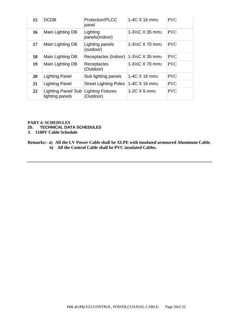
VOL-II (TS) E23-CONTROL, POWER,COAXIAL CABLE- Page 26of 25
15 DCDB Protection/PLCC panel
1-4C X 16 mm2 PVC
16 Main Lighting DB Lighting panels(Indoor)
1-3½C X 35 mm2 PVC
17 Main Lighting DB Lighting panels (outdoor)
1-3½C X 70 mm2 PVC
18 Main Lighting DB Receptacles (Indoor) 1-3½C X 35 mm2 PVC
19 Main Lighting DB Receptacles (Outdoor)
1-3½C X 70 mm2 PVC
20 Lighting Panel Sub lighting panels 1-4C X 16 mm2 PVC
21 Lighting Panel Street Lighting Poles 1-4C X 16 mm2 PVC
22 Lighting Panel/ Sub lighting panels
Lighting Fixtures (Outdoor)
1-2C X 6 mm2 PVC
PART 4: SCHEDULES 25. TECHNICAL DATA SCHEDULES
3. 1100V Cable Schedule
Remarks:- a) All the LV Power Cable shall be XLPE with insulated armoured Aluminum Cable.
b) All the Control Cable shall be PVC insulated Cables.
VOL-II (TS) E24-SUBSTATION LIGHTING-Page1 of 10
ODISHA POWER TRANSMISSION CORPORATION LIMITED
OFFICE OF THE SR. GENERAL MANAGER,
CENTRAL PROCUREMENT CELL,
JANAPATH, BHUBANESWAR – 751022.
TECHNICAL SPECIFICATION
FOR
SUB STATION LIGHTING

VOL-II (TS) E24-SUBSTATION LIGHTING-Page2 of 10
SUBSTATION LIGHTING
TABLE OF CONTENTS
ORISSA POWER TRANSMISSION CORPORATION LIMITED ................................................... 1
1. GENERAL ............................................................................................................... 4
1. SYSTEM DESCRIPTION ......................................................................................... 5
1.1 Normal lighting - AC .................................................................................................................... 5
1.2 Emergency lighting - AC ............................................................................................................. 5
1.3 Emergency lighting - DC ............................................................................................................. 5
1.4 Emergency lighting - portable ...................................................................................................... 5
1.5 Temperature Rise ............................................................................................................................ 5
2. LIGHTING FIXTURES ............................................................................................ 5
2.1 General ............................................................................................................................................ 5
2.2 Accessories .................................................................................................................................... 6
2.2.1 Reflectors ................................................................................................................................ 6
2.2.2 Lamp holders ......................................................................................................................... 6
2.2.3 Ballasts(if required) ............................................................................................................... 6
2.2.4 Capacitors ............................................................................................................................... 7
2.2.5 Lamps ..................................................................................................................................... 7
2.3 Receptacles ..................................................................................................................................... 7
3. LIGHTING POLES .................................................................................................. 8
4. LIGHTING WIRES & CABLES ............................................................................... 8
5. TESTS AND TEST REPORTS................................................................................ 9
6. LIGHTING SYSTEM INSTALLATION WORKS ...................................................... 9
6.1 General ........................................................................................................................................... 9
6.2 Flood lights. .................................................................................................................................... 9
6.3 Lighting fixtures for flood lights..................................................................................................... 9
6.4 Lighting panels ............................................................................................................................. 10
6.5 Street lighting poles ...................................................................................................................... 10
7. TECHNICAL PARAMETERS OF LIGHTING TRANSFORMERS ........................ 10
8. EMERGENCY PORTABLE LIGHTING FIXTURES .............................................. 10
VOL-II (TS) E24-SUBSTATION LIGHTING-Page3 of 10
9. CEILING FANS AND REGULATORS ................................................................... 11
10. FOUNDATION AND CIVIL WORKS ................................................................... 11
11. GROUNDING ....................................................................................................... 11
12. TESTING AND COMMISSIONING ...................................................................... 11
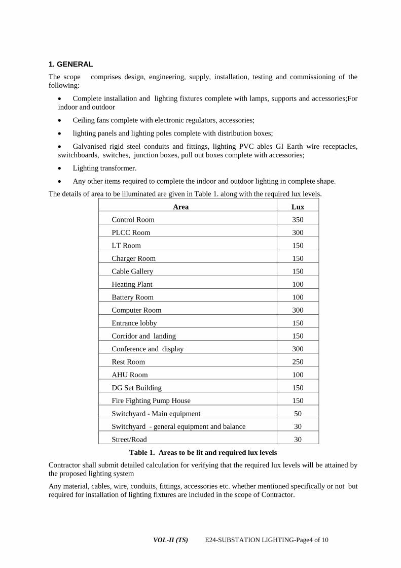
VOL-II (TS) E24-SUBSTATION LIGHTING-Page4 of 10
1. GENERAL
The scope comprises design, engineering, supply, installation, testing and commissioning of the
following:
Complete installation and lighting fixtures complete with lamps, supports and accessories;For
indoor and outdoor
Ceiling fans complete with electronic regulators, accessories;
lighting panels and lighting poles complete with distribution boxes;
Galvanised rigid steel conduits and fittings, lighting PVC ables GI Earth wire receptacles,
switchboards, switches, junction boxes, pull out boxes complete with accessories;
Lighting transformer.
Any other items required to complete the indoor and outdoor lighting in complete shape.
The details of area to be illuminated are given in Table 1. along with the required lux levels.
Area Lux
Control Room 350
PLCC Room 300
LT Room 150
Charger Room 150
Cable Gallery 150
Heating Plant 100
Battery Room 100
Computer Room 300
Entrance lobby 150
Corridor and landing 150
Conference and display 300
Rest Room 250
AHU Room 100
DG Set Building 150
Fire Fighting Pump House 150
Switchyard - Main equipment 50
Switchyard - general equipment and balance 30
Street/Road 30
Table 1. Areas to be lit and required lux levels
Contractor shall submit detailed calculation for verifying that the required lux levels will be attained by
the proposed lighting system
Any material, cables, wire, conduits, fittings, accessories etc. whether mentioned specifically or not but
required for installation of lighting fixtures are included in the scope of Contractor.
VOL-II (TS) E24-SUBSTATION LIGHTING-Page5 of 10
1. SYSTEM DESCRIPTION
1.1 Normal lighting - AC
AC lights will be connected to AC lighting panels. All the lights connected to the AC lighting system
in different areas will be connected to the main lighting distribution boards to be supplied.
1.2 Emergency lighting - AC
This system will be available in control room building, switchyard and diesel generator building. AC
lighting load will be connected to this system which will be normally ‘ON’. The lighting panels of this
system will be connected to the Emergency lighting board which is fed from diesel generator during the
emergency.
1.3 Emergency lighting - DC
DC emergency lighting fixtures operated from the DC system shall be provided in strategic locations
so that the operating personnel can safely find their way during a total AC failure. These lights will be
normally „OFF‟ and will be switched „ON‟ automatically when under voltage occurs in the AC mains
lighting distribution board.
1.4 Emergency lighting - portable
Emergency portable light shall be provided as per relevant clause of this section. Three portable lights
for control room and two portable lights for PLCC room shall be provided for every substation.
1.5 Temperature Rise
All lighting fixtures and accessories shall be designed to have a low temperature rise according to IEC
598 Part-I/ IS 10322 (Part-4).Temperature rise of panels should be as per IS 8623 (Part-l)/IEC 439-1.
2. LIGHTING FIXTURES
2.1 General
Fixture shall conform to latest IS / IEC .and its latest amendment.
All fixtures shall be designed for minimum glare. The finish of the fixtures shall be such that no bright
spots are produced either by direct light source or by reflection.
All lighting fixtures shall be complete with required lamps such as LED (to be fitted inside switch yard
and all street light ), & LED light (adopt as per Govt nerms for energy efficiency) for indoor lighting..
LED lamp fixtures shall be complete with all necessary wiring and accessories such as ballasts,
ignitors, power factor improvement capacitors etc if required. These shall be mounted in the fitting
assembly only. The Contractor shall indicate starting time of these lamps to attain full light output.
Curves for starting characteristics with varying supply voltage etc. are to be furnished by the
Contractor.
Flood lighting shall have suitable base plate/frame for mounting on structural steel member.
Each fixture (other than bulk head fixtures) shall have terminal blocks suitable for 2.5 mm2 stranded
flexible copper conductor. The internal wiring should be completed by the manufacturer and
terminated on the above terminal blocks. The Contractor shall specifically furnish details of internal
size of wires and type of insulation. The terminal blocks shall be as specified under General Equipment
and Substation Accessories (GESA) section of this Specification.
Each lighting fixture shall be provided with an earthing terminal suitable for connection to 16 SWG GI
earthing conductors.
VOL-II (TS) E24-SUBSTATION LIGHTING-Page6 of 10
All metal or metal enclosed parts of the housing shall be suitably constructed so as to ensure
satisfactory earthing continuity throughout the fixture up to the earthing terminal.
The mounting facility and conduit knock-outs for the fixtures shall be provided and shall be suitable for
20 mm conduit entry.
On completion of manufacture, all surfaces of the fixtures shall be thoroughly cleaned and degreased.
The fixtures shall be free from scale, rust, sharp edges and burrs.
The housing shall be stove-enamelled or vitreous enamelled or anodised aluminium as indicated in the
specification of the relevant fixture.
All enamel finishing shall have a minimum thickness of 2 mils for outside surface and 1.5 mils for
inside surface. The finish shall be non-porous and free from blemishes, blisters and fading.
The surface shall be scratch resistant and shall show no sign of cracking or flaking when bent through
90 degrees. over 1.5 inch die mandrel.
All light reflecting surfaces shall have optimum light reflecting coefficient so as to ensure the overall
light output as specified.
The different types of lighting fixtures to be provided shall be to the approval of the OPTCL.
REMARKS: ALL THE LAMPS TO BE USED INSIDE & OUTSIDE THE SUB-STATION
AREA SHALL BE OF “LED” ONLY. BIDDERS ARE ADVISED TO QUOTE
ACCORDINGLY.
2.2 Accessories
2.2.1 Reflectors
The reflectors shall be manufactured from sheet steel or aluminium more applicable of not less than 22
SWG thickness. They shall be securely fixed and of captive type.
2.2.2 Lamp holders
Lamp holders shall preferably be for LED lamps etc.. Holders shall be designed and manufactured in
accordance with relevant standard to give long and satisfactory service.
2.2.3 Ballasts(if required)
Ballasts shall be designed, manufactured and supplied in accordance with IS 3021 and function
satisfactorily under site condition specified. The ballasts shall be designed to have a long service life.
The power loss in ballasts (if required)for LED lamps shall not be more than the specified watts as per
relevant standard and for the fluorescent lamps it shall be the minimum commercially available in the
industry.
Ballasts shall be mounted using self locking anti-vibration fixing and shall be easy to remove without
dismantling the fixtures. They shall be totally enclosed units.
The ballasts shall be of the inductive, heavy duty type, filled with thermosetting, insulating, moisture
repellent polyester compound filled under pressure or vacuum. The ballast wiring shall be of copper
wire. Ballasts shall be designed for maximum winding temperature rise of 55C under rated conditions.
They shall be free from hum. Ballasts for LED lamps shall be provided with suitable tapping to set the
voltage within the range specified. End connections and taps shall be brought out in a suitable terminal
block, rigidly fixed to the ballast enclosure.
Separate ballasts for each lamp shall be provided in case of multi-lamp fixtures.
The Contractor shall submit general arrangement and wiring diagram with all terminal details for
approval of the OPTCL.

VOL-II (TS) E24-SUBSTATION LIGHTING-Page7 of 10
2.2.4 Capacitors
Capacitors shall have a constant value of capacitance and shall be connected across the supply of
individual lamp circuits.
Capacitors shall be suitable for operation at the supply voltage as specified and shall have a value of
capacitance so as to correct the power factors of its corresponding lamp circuit to the extent of 0.98 lag.
Capacitors shall be hermetically sealed in a metal enclosure.
2.2.5 Lamps
The LED lamps to be supplied shall conform to IS 9974. LED lamps shall be suitable for use in any
position. Restrictions, if any, shall be clearly stated. The lamps shall be capable of withstanding small
vibrations with out breakage of connections at lead-in wires and filament electrodes.
The constructional features of LED lamps for special applications shall be clearly brought out in the
bid.
The Bidder shall furnish typical wiring diagrams for all fittings including all accessories. The diagrams
shall include technical details of accessories i.e. ignitors, ballasts, capacitors etc.
2.3 Receptacles
All receptacles shall be of cast steel or aluminium, heavy duty type, suitable for fixing on wall or
column and complete with individual switch.
In general the receptacles to be installed are of the following types:
Type RO-15A, 240V, 2 pole, 3 pin type with third pin grounded, metal clad with gasket having
cable gland entry suitable for 2 core 6 mm2 PVC armoured cable and a metallic cover fixed to it with a
metallic chain. Receptacles shall be suitable for installation in moist location and/ or outdoor. The
switch shall be of rotary type. Receptacles shall be housed in an enclosure made out of 2 mm thick GI
sheet with hinged doors with padlocking arrangements. Door shall be lined with good quality gaskets.
This shall conform to IP 55.
Type RI-Combination of 5A and 15A, 240V, 3 pin type with third pin grounded, suitable for
flush mounting. The switch shall be of piano key type and shall be flush mounted.
Type RP-63A, 415V, 3 phase, 4 pin interlocked plug and switch with earthing contacts. Other
requirements shall be same as type RO. The receptacle shall be suitable for 3½ core 35mm2 / 3½ core
70mm2 aluminium conductor cable entry and shall also be suitable for loop-in-loop-out connection of
cables of identical size. Receptacle shall be suitable for outdoor application. Receptacles shall be
housed in a box made out of 2 mm thick G. I. sheet, with hinged door with padlocking arrangement.
Door shall be lined with good quality gaskets. This shall conform to IP 55.
3. LIGHTING POLES
The Contractor shall supply, the following types of hot dip galvanised steel tubular lighting poles
required for street lighting:
a) Type Al street lighting pole - for one fixture
b) Type El post top lantern pole - for one fixture
Street/flood light poles shall conform to the drawings approved by the OPTCL.
Lighting poles shall be complete with fixing brackets and junction boxes. Junction boxes should be
mounted above ground level at 1 mtr height from the ground.
The lighting poles shall be steel hot dip galvanised
The galvanised sheet steel junction box for the street lighting poles shall be completely weather proof
conforming to IP 55 and provided with a lockable door and HRC fuse mounted on a fuse carrier and
VOL-II (TS) E24-SUBSTATION LIGHTING-Page8 of 10
fuse base assembly. The terminals shall be stud type and suitable for two nos. 16mm2 cables.
Necessary arrangement for cable glands along with supply of double compression glands are included
in Contractor’s scope.
Wiring from junction box at the bottom of the pole (minimum height from the bottom of the pole shall
be 1.0mtrs) to the fixture at the top of the pole shall be 2.5 mm2 wire.
4. LIGHTING WIRES & CABLES
The wiring used for lighting shall be of 1100V grade, PVC insulated cable of standard products of
reputed manufacturers.
The conductor sizes for wires used for point wiring beyond lighting panels shall be single core 4 mm2,
6mm2 and 10mm2 stranded aluminium wires and 2.5 mm2 stranded copper wire.
The wires used for connection of a lighting fixture from area rest junction box or for loop-in loop-out
connection between two fluorescent fixtures shall be single core copper stranded conductor, 1100V
grade flexible PVC insulated cords, unsheathed, conforming to IS 694 with nominal conductor cross
sectional areas of 2.5mm2.
The Contractor’s scope covers supply of all wiring, cabling and accessories.
The wires shall be colour coded as follows:
Red for R - Phase
Yellow for Y - Phase
Blue for B - Phase
Black for Neutral
White for DC (Positive)
Grey for DC (Negative)
5. TESTS AND TEST REPORTS
Type tests, acceptance tests and routine tests for the lighting fixtures and accessories covered by this
specification shall be carried out as per the relevant standard for the respective fixtures and their
accessories.
Manufacturer’s type and routine test certificates shall be submitted for the fixtures and accessories.
Type test certificates shall be furnished along with the bid.
Rates for type tests for all types of fixtures and accessories for light fittings as required under relevant
section of this specification shall be provided in the relevant price schedules.
6. LIGHTING SYSTEM INSTALLATION WORKS
6.1 General
In accordance with the specified installation instructions as shown on manufacturer’s drawings or as
directed by Project Manager. Contractor shall supply, erect, install, test and put into commercial use all
the electrical lighting equipment included in the contract. Equipment shall be installed in a neat,
workmanlike manner so that it is level, plumb, square and properly aligned and oriented. Tolerances
shall be as established in manufacturer’s drawings or as stipulated by Project Manager.
The Contractor shall prepare the lighting layout and erection drawings and obtain the Project Manager’s
approval before commencing the erection works.
VOL-II (TS) E24-SUBSTATION LIGHTING-Page9 of 10
6.2 Flood lights.
Contractor shall install flood lights on switchyard structures to be erected inside switchyard. The GI
structural are also suitable for protection from lightening by providing spikes cones at all the column
peak. Proper design in this respect to be carried out along with numbers of such towers required.
Plotting of lightening protection area showing details of equipment installed in switch yard. A platform
provided in the mast tower shall be used for fixing of lighting fixtures.
Fixtures shall be mounted on galvanised making use of shop provided holes or by suitable clamps. No
cutting or drilling of galvanised structure is permitted.
The Contractor shall mount the assembled fittings and install necessary cabling.
6.3 Lighting fixtures for flood lights
Flood lights shall be mounted on steel base facing the tentative direction shown on drawings. Fixing
holes shall be provided with slot to turn the fixture by approximately 5 degrees
on both sides. Bolts
shall be finally tightened with spring washer. The Contractor shall supply and install the steel base,
channels, angles etc. for fixing the flood light on the flood light towers. Terminal connection to the
flood light shall be through flexible conduits, and these flexible conduits shall be included in the
installation rate of fixture itself.
The scope of Contractor shall include the supply of necessary brackets and sundry material, for
installation of lighting fixtures.
6.4 Lighting panels
Lighting panels shall be erected at the locations to be indicated in the approved drawings.
Necessary foundations and/or supporting structures for all outdoor type lighting panels and necessary
supporting structures for indoor lighting panels shall be provided by the Contractor.
6.5 Street lighting poles
Street lighting poles shall be installed as per the approved drawings.
Steel tubular hot dip galvanised pole,s which are specified for the above purpose are to be installed as
per the approved lay out for street lighting system. Contractor shall erect the poles (including
foundation works), mount the assembled fittings and install necessary cabling.
7. TECHNICAL PARAMETERS OF LIGHTING TRANSFORMERS
i) Type of transformer Dry type natural air
ii) Rating 1 00 kVA or 75kVA
iii) Voltage ratio 415/415 volts
iv) No. of phase Three
v) Frequency 50Hz
vi) Winding connection Dyn 1
vii) Class of insulation B class
viii) Percentage Impedance 4%, 10%
ix) No. of taps and steps 5 in steps of 2.5%
x) Reference standard IS 2026
xi) Any latest amendment standards of the above.

VOL-II (TS) E24-SUBSTATION LIGHTING-Page10 of 10
Transformers shall be located in ACDB room, in separate enclosure. Enclosure shall have degree of
protection not less than IP 42 as per IS 2147.
8. EMERGENCY PORTABLE LIGHTING FIXTURES
The portable emergency lighting fixtures supplied shall have a built in battery rated for six hours and be
complete with battery chargers and solid state inverters, and be supplied with all necessary supporting
brackets of galvanised steel suitable for wall/column mounting..
The portable emergency lighting fixtures shall be of a single unit, completely tropicalised, suitable for
prolonged use with no maintenance, and shall light up automatically in the event of failure of normal
supply.
The Contractor shall submit schematic along with all details and general arrangement drawing for
approval.
9. CEILING FANS AND REGULATORS
The Contractor shall supply 1400 mm sweep ceiling fans complete with electronic regulator and switch,
suspension rod, canopy and accessories.
The Contractor shall supply the switch, electronic regulator and board for mounting switch and
electronic regulator.
Winding of the fans and regulators shall be insulated with Class-E insulating material. Winding shall
be of copper wire.
Electronic regulator with smooth control shall be provided.
Precautions shall be taken in manufacture of fans and regulators to ensure reasonable degree of silence
at all speeds.
Type tests, acceptance tests and routine tests for the fans and regulators shall be carried out as per latest
relevant standard.
Fans and electronic regulators shall be from established manufacturers or brands.
10. FOUNDATION AND CIVIL WORKS
All foundations and civil works shall be included in the Contractor’s scope of work. Civil works shall
be in accordance with the relevant part of this specification.
11. GROUNDING
All lighting panels, junction boxes, fixtures, conduits etc. shall be grounded in compliance with the
provision of I.E. Rules.
Ground connections shall be made from nearest available station ground grid. All connections to
ground grid shall be done by arc welding.
Lighting panels shall be directly connected to ground grid by two 50 x 6mm G.S. flats.
A continuous ground conductor of 16 SWG GI wire shall be connected to each panel ground bus. All
junction boxes, lighting fixtures shall be connected to this 16 SWG ground conductor.
All lighting poles shall be earthed as per standard. 16 SWG GI wire shall be taken up to junction box
from the lighting fixture.

VOL-II (TS) E24-SUBSTATION LIGHTING-Page11 of 10
12. TESTING AND COMMISSIONING
On completion of erection work, the Contractor shall request the OPTCL to undertake the inspection as
required by this Specification.
The OPTCL shall arrange for joint inspection of the installation for completeness and correctness of the
work. Any defect pointed out during such inspection shall be promptly rectified by the Contractor.
The installation shall be tested and commissioned in the presence of the Contractor and OPTCL
The Contractor shall provide all men, material and equipment required to carry out the tests.
All rectification, repairs or adjustment work found necessary during inspection, testing and
commissioning shall be carried out by the Contractor, without any extra cost to the Employer.
The Contractor shall measure and furnish to the Project Manager, the actual lux level in all the areas of
the substation to prove compliance to this specification.
** Armoured PVC cables are to be used for the switch yard lighting, street lighting and any other
out door lighting system.
** For indoor lighting ,each fixture shall be controlled by one switch.
** Minimum two nos 5 Amp multi purpose power sockets with switch are to be provided in each
switch.
*** Contractor to furnish the design details for the locations (like Switch yard area,Road street
light,Control room building area,Quarter ,Gate etc), which can be adopted after approval from
OPTCL. Design to be carried out as per the LUX level indicated at the beginning of this chapter.

VOL-II (TS) E24-SUBSTATION LIGHTING-Page12 of 10
TECHNICAL SPECIFICATION FOR LED FLOOD / NORMAL LIGHT FITTINGS 1 PH A.C OPERATION 1.GENERAL DESCRIPTION
LED Flood/Normal Light luminaries of 240V, A.C,50 Hz ,suitably decided the wattage of the lamp (to be decided after detail Engineering) in Single piece High Pressure Die Cast Aluminium alloy Housing having high conductivity acting as heat sink, with Powder coating with suitable colour with distortion free, clear, Heat Resistant Toughened UV stabilized Glass in the front fixed to the die cast Aluminium frame which shall be fixed to the housing with high quality long lasting Neoprine Rubber gasket duly impregnated with insecticide and water repellant chemical on the periphery of lamp compartment by means of stainless steel screws to render it dust proof, water proof and vermin proof and having minimum IP-65 Protection conforming to IS:10322 (part-2) – 1982.
Note: The capacity LED Luminary is to be suitably decided after conducting the detail Engineering for the locations , where these Luminaries are to be used. The Locations are generally in EHV grade Sub-station switch yard area,Street Lighting, Control Room Building, Colony Quarters etc. Details design for adoption of LED Luminary system to be furnished for review of design and its acceptance. Latest practice of adoption of these system are to be strictly followed.
2. TRAINING :
Train the staff on Hardware /Software ,installation, commissioning and maintenance of the Luminaries at different locations (Different Sub-stations).
3. TECHNICAL SPECIFICATIONS:
The LED Luminaries are as per the following parameters
a Mid Power White LED's Should be of reputed make as indicated in the Tender specification.
b Wattage of Mid Power White LED,s offered Low power LED 5252 0.3W
c LED Lumens
d Life span as per LM70( @70%) light output >50000 Hrs. 0r Better
Lux at centre at height of 4.5 meter >150 LUX 0r Better
e ngle) >0.35 0r Better
f Luminary Efficacy >65 0r Better
g Control of Distribution Fully Cutoff
i Driver current(With Constant Current Driver) <100mA/LED 0r Better
j Electronic Efficiency@230V >85% 0r Better k Beam angle of the Luminary > 120° 0r Better

VOL-II (TS) E24-SUBSTATION LIGHTING-Page13 of 10
l color Temperature of LEDs 6500K to 7500K 0r Better
m
P/N junction temperature (High thermal conduction must be achieved by silicon heat conducting greases as adhesive <85 ºC 0r Better
n Luminary Body Temperature
The Body Temperature shall be <(Ambient+35º C) even after continuous burning of Luminary for 24 Hrs.0r Better
o color Rendering Index(CRI) >70 0r Better
p weight
Preferably less weight & may be of Maximum up to 4 Kgs (comfortably can be carried and fixed)
B ELECTRICAL
a AC Input Voltage Range 100V TO 270V AC
b
AC Input frequency .( The LED circuitry shall function at an operating frequency that must be greater than 120 Hz to prevent perceptible flicker to the unaided eye over the entire voltage range specified above. )
47 ~ 53Hz
c
Power Factor (Source Power Factor varies from 0.5 Lag to 0.5 Lead)
> 0.95 0r Better
d
Luminary Wattage variance at 100 V to 270 V
± 10%
e
Luminary Lux Levels Variance at 100 V to 270 V
± 5%
f Total Harmonic Distortion(THD) < 15% 0r Better
g Electrical Connection System 3 wire system (Phase,Neutral & Gnd)
h
System of earthing (The luminaries offered shall conform to Level-1 classification)
Solidly grounded
i
There shall be electrical isolation between input and output circuits of the driver.
C MECHANICAL
a
Construction of Casing High Pressure Die Cast Aluminum. Should be durable for extreme climatic conditions.
b
Finish
Powder Coating and gray/black color and should be durable. The colour should not fade in extreme climate conditions.
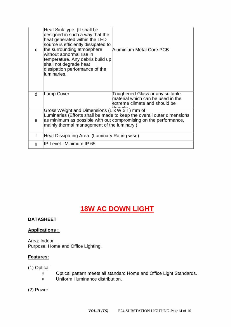
VOL-II (TS) E24-SUBSTATION LIGHTING-Page14 of 10
c
Heat Sink type (It shall be designed in such a way that the heat generated within the LED source is efficiently dissipated to the surrounding atmosphere without abnormal rise in temperature. Any debris build up shall not degrade heat dissipation performance of the luminaries.
Aluminium Metal Core PCB
d Lamp Cover Toughened Glass or any suitable material which can be used in the extreme climate and should be durable.
e
Gross Weight and Dimensions (L x W x T) mm of Luminaries (Efforts shall be made to keep the overall outer dimensions as minimum as possible with out compromising on the performance, mainly thermal management of the luminary )
f Heat Dissipating Area (Luminary Rating wise)
g IP Level –Minimum IP 65
18W AC DOWN LIGHT
DATASHEET Applications : Area: Indoor Purpose: Home and Office Lighting. Features: (1) Optical
» Optical pattern meets all standard Home and Office Light Standards.
» Uniform illuminance distribution. (2) Power
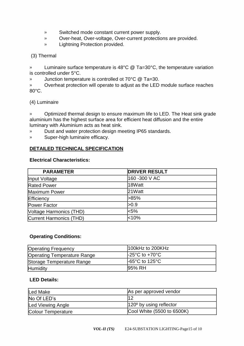
VOL-II (TS) E24-SUBSTATION LIGHTING-Page15 of 10
» Switched mode constant current power supply.
» Over-heat, Over-voltage, Over-current protections are provided.
» Lightning Protection provided. (3) Thermal
» Luminaire surface temperature is 48°C @ Ta=30°C, the temperature variation is controlled under 5°C.
» Junction temperature is controlled ot 70°C @ Ta=30.
» Overheat protection will operate to adjust as the LED module surface reaches 80°C. (4) Luminaire
» Optimized thermal design to ensure maximum life to LED. The Heat sink grade aluminium has the highest surface area for efficient heat diffusion and the entire luminary with Aluminium acts as heat sink.
» Dust and water protection design meeting IP65 standards.
» Super-high luminaire efficacy.
DETAILED TECHNICAL SPECIFICATION Electrical Characteristics:
PARAMETER DRIVER RESULT
Input Voltage 160 -300 V AC
Rated Power 18Watt
Maximum Power 21Watt
Efficiency >85%
Power Factor >0.9
Voltage Harmonics (THD) <5%
Current Harmonics (THD) <10%
Operating Conditions:
Operating Frequency 100kHz to 200KHz
Operating Temperature Range -25°C to +70°C
Storage Temperature Range -65°C to 125°C
Humidity 95% RH
LED Details:
Led Make As per approved vendor
N O L D’s 12
Led Viewing Angle 120º by using reflector
Colour Temperature Cool White (5500 to 6500K)

VOL-II (TS) E24-SUBSTATION LIGHTING-Page16 of 10
Luminous Flux >2160 Lumens
Life Span > 80,000 Hours
Colour Rendering Index >70 Ra
LED Luminary Details:
Body Alluminium Body
Heat Sink
Optimized thermal design to ensure maximum life to LED. The Heat sink grade aluminium has the highest surface area for efficient heat diffusion and the entire luminary with Aluminium acts as heat sink.
Dust and Water protection IP 65 Standards
Protection Parameters:
Over-Current Protection Inbuilt
Short-Circuit Protection Inbuilt
Over-Voltage Protection Inbuilt
Over-Temperature Protection 135 °C
Dust and Water Protection IP 65
Lightning Protection Inbuilt
50W AC LOW BAY LIGHT
LED bay light fixture is designed and developed to replace traditional high bay or low bay fixtures for industrial and other rugged applications. Light weighted and easy for installation, the LED High Bay/Low Bay fixtures are all designed to offer maximum energy saving, substantially reduced maintenance costs and superior quality.
Major Applications :
Factory production floors, Workshop, Warehouses, Road toll gates, Petrol stations, Supermarkets, Sports stadiums, Convention center halls, Airport passenger halls, etc., where high ceiling lighting required.
Features :
1)Low power consumption. More than 60% energy saving compared to conventional HID/HPS.
2) Environmental friendly. Lead and mercury free. Long operation life time, above 50,000hours. Low maintenance costs.
3)Voltage input 160-300 V AC, 4)Instant ON/OFF operation.
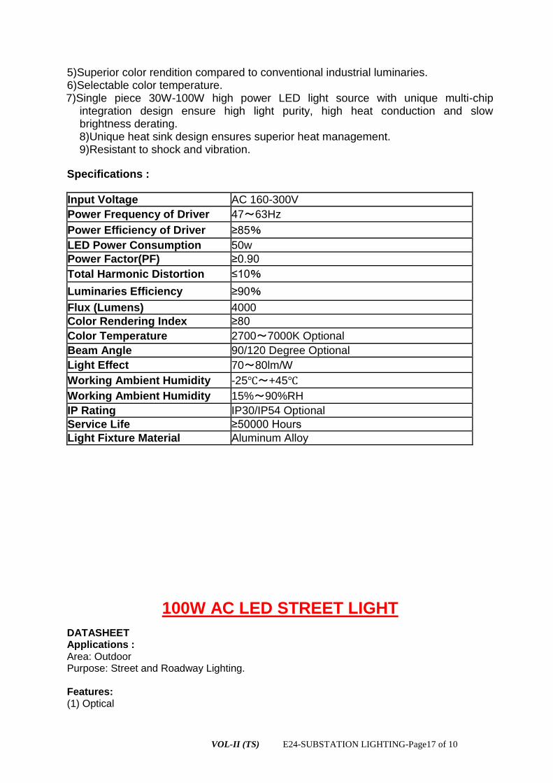
VOL-II (TS) E24-SUBSTATION LIGHTING-Page17 of 10
5)Superior color rendition compared to conventional industrial luminaries. 6)Selectable color temperature. 7)Single piece 30W-100W high power LED light source with unique multi-chip
integration design ensure high light purity, high heat conduction and slow brightness derating.
8)Unique heat sink design ensures superior heat management. 9)Resistant to shock and vibration.
Specifications :
Input Voltage AC 160-300V
Power Frequency of Driver 47~63Hz
Power Efficiency of Driver ≥8 %
LED Power Consumption 50w
Power Factor(PF) ≥
Total Harmonic Distortion ≤1 %
Luminaries Efficiency ≥ %
Flux (Lumens) 4000
Color Rendering Index ≥8
Color Temperature 2700~7000K Optional
Beam Angle 90/120 Degree Optional
Light Effect 70~80lm/W
Working Ambient Humidity -25℃~+45℃
Working Ambient Humidity 15%~90%RH
IP Rating IP30/IP54 Optional
Service Life ≥ H s
Light Fixture Material Aluminum Alloy
100W AC LED STREET LIGHT
DATASHEET Applications : Area: Outdoor Purpose: Street and Roadway Lighting. Features: (1) Optical

VOL-II (TS) E24-SUBSTATION LIGHTING-Page18 of 10
» Optical pattern meets all standard Street Light Standards.
» Uniform illuminance distribution. (2) Power
» Switched mode constant current power supply.
» Over-heat, Over-voltage, Over-current protections are provided.
» Lightning Protection provided. (3) Thermal
» Luminaries surface temperature is 48°C @ Ta=30°C, the temperature variation is controlled under 5°C.
» Junction temperature is controlled ot 70°C @ Ta=30.
» Overheat protection will operate to adjust as the LED module surface reaches 80°C. (4) Luminaire
» Optimized thermal design to ensure maximum life to LED. The Heat sink grade aluminium has the highest surface area for efficient heat diffusion and the entire luminary with Aluminium acts as heat sink.
» Dust and water protection design meeting IP65 standards.
» Super-high luminaire efficacy. DETAILED TECHNICAL SPECIFICATION Electrical Charatcteristics
PARAMETER PROMPT DRIVER RESULT
Input Voltage 160 -300 VAC
Rated Power 100W
Maximum Power 115W
Efficiency >85%
Power Factor >0.9
Voltage Harmonics (THD) <5%
Current Harmonics (THD) <10%
Operating Conditions:
Operating Frequency 100kHz to 200KHz
Operating Temperature Range -25°C to +70°C
Storage Temperature Range -65°C to 125°C
Humidity 95% RH
LED Details:
Led Make As per approved vendor
N L D’s 48-70
Led Viewing Angle 120º by using reflector
Colour Temperature Cool White (5500 to 6500K)
Luminous Flux >8500 Lumens
Life Span > 50,000 Hours
Colour Rendering Index >70 Ra
LED Luminary Details:
Body Alluminium Die casting Body

VOL-II (TS) E24-SUBSTATION LIGHTING-Page19 of 10
Heat Sink
Optimized thermal design to ensure maximum life to LED. The Heat sink grade aluminium has the highest surface area for efficient heat diffusion and the entire luminary with Aluminium acts as heat sink.
Protection IP 65 Standards for Dust and Water
Protection Parameters:
Over-Current Protection Inbuilt
Short-Circuit Protection Inbuilt
Over-Voltage Protection Inbuilt
Over-Temperature Protection 135 °C
Dust and Water Protection IP 65
Lightning Protection Inbuilt
120/150W AC LED FLOOD LIGHT
DATASHEET Applications : Area: Outdoor Purpose: Street and Roadway And Area Lighting. Features: (1) Optical
» Optical pattern meets all standard Street Light Standards.
» Uniform illuminance distribution. (2) Power
» Switched mode constant current power supply.
» Over-heat, Over-voltage, Over-current protections are provided.
» Lightning Protection provided. (3) Thermal
» Luminaries surface temperature is 48°C @ Ta=30°C, the temperature variation is controlled under 5°C.
» Junction temperature is controlled ot 70°C @ Ta=30.
» Overheat protection will operate to adjust as the LED module surface reaches 80°C.

VOL-II (TS) E24-SUBSTATION LIGHTING-Page20 of 10
(4) Luminaire
» Optimized thermal design to ensure maximum life to LED. The Heat sink grade aluminium has the highest surface area for efficient heat diffusion and the entire luminary with Aluminium acts as heat sink.
» Dust and water protection design meeting IP65 standards.
» Super-high luminaire efficacy. DETAILED TECHNICAL SPECIFICATION Electrical Charatcteristics
PARAMETER PROMPT DRIVER RESULT
Input Voltage 160 -300 VAC
Rated Power 120W
Maximum Power 140W
Efficiency >85%
Power Factor >0.9
Voltage Harmonics (THD) <5%
Current Harmonics (THD) <10%
Operating Conditions:
Operating Frequency 100kHz to 200KHz
Operating Temperature Range -25°C to +70°C
Storage Temperature Range -65°C to 125°C
Humidity 95% RH
LED Details:
Led Make As per approved vendor
N L D’s 48-70
Led Viewing Angle 120º by using reflector
Colour Temperature Cool White (5500 to 6500K)
Luminous Flux >8500 Lumens
Life Span > 50,000 Hours
Colour Rendering Index >70 Ra
LED Luminary Details:
Body Alluminium Die casting Body
Heat Sink
Optimized thermal design to ensure maximum life to LED. The Heat sink grade aluminium has the highest surface area for efficient heat diffusion and the entire luminary with Aluminium acts as heat sink.
Protection IP 65 Standards for Dust and Water

VOL-II (TS) E24-SUBSTATION LIGHTING-Page21 of 10
Protection Parameters:
Over-Current Protection Inbuilt
Short-Circuit Protection Inbuilt
Over-Voltage Protection Inbuilt
Over-Temperature Protection 135 °C
Dust and Water Protection IP 65
Lightning Protection Inbuilt
TS-Vol-II E25-TESTING INSTRUMENTS- Page 1 of 11
ODISHA POWER TRANSMISSION CORPORATION LIMITED
TECHNICAL SPECIFICATION
FOR
TESTING INSTRUMENTS AND MAINTENANCE KITS
OTHER TOOLS & PLANTS
&
FURNITURE
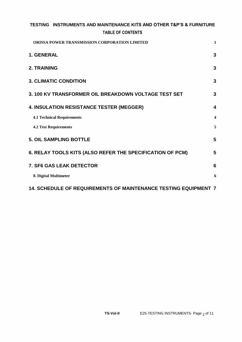
TS-Vol-II E25-TESTING INSTRUMENTS- Page 2 of 11
TESTING INSTRUMENTS AND MAINTENANCE KITS AND OTHER T&P’S & FURNITURE
TABLE OF CONTENTS
ORISSA POWER TRANSMISSION CORPORATION LIMITED 1
1. GENERAL 3
2. TRAINING 3
3. CLIMATIC CONDITION 3
3. 100 KV TRANSFORMER OIL BREAKDOWN VOLTAGE TEST SET 3
4. INSULATION RESISTANCE TESTER (MEGGER) 4
4.1 Technical Requirements 4
4.2 Test Requirements 5
5. OIL SAMPLING BOTTLE 5
6. RELAY TOOLS KITS (ALSO REFER THE SPECIFICATION OF PCM) 5
7. SF6 GAS LEAK DETECTOR 6
8. Digital Multimeter 6
14. SCHEDULE OF REQUIREMENTS OF MAINTENANCE TESTING EQUIPMENT 7

TS-Vol-II E25-TESTING INSTRUMENTS- Page 3 of 11
1. GENERAL
The testing and maintenance equipment covered here are generally meant for carrying out testing and
measurement at site and shall be complete with all materials and accessories. These shall be robust in
design, so that they give accurate results even in adverse site conditions.
All equipment furnished shall be of reputed make, type tested and shall be subjected to acceptance and
routine tests in accordance with the requirements stipulated under respective equipment specification.
At least two sets of descriptive leaflets, catalogues, outline drawing, principles of operation etc. shall be
sent along with the offer, for all the equipment offered. Weight and dimensions of items should also
be mentioned.
Four sets of inspection and calibration report, operation and maintenance manual shall be sent along
with Despatch documents. One set will be kept inside the equipment.
In the event of bidder offering equipment manufactured by different manufacturers, it will be his
responsibility to fully co-ordinate the activities of each manufacturer in such a way that the complete
equipment contracted for, is manufactured, supplied and guaranteed for successful operation.
2. TRAINING
Necessary training shall be provided to Employer's personnel for using and maintaining the equipment
at Employer's premises.
3. CLIMATIC CONDITION
The equipment covered under this specification shall be suitable for operation under climatic condition
stated else where in the specification. The offered equipment as such shall be suitable for satisfactory
operation under the tropical climate.
3. 100 KV TRANSFORMER OIL BREAKDOWN VOLTAGE TEST SET
The equipment offered shall be suitable for determination of electric strength (breakdown voltage) of
insulating oil upto 100 KV to IS:335 when measured in accordance with IS:6792.
The test cell shall be as per IS:6792 suitable for BDV upto 100 KV without external flashover.
The unit shall be of composite type having control unit and high voltage transformer in a common
cabinet with necessary partition. HV chamber interlocking and zero start interlocking shall be provided.
The unit shall have motorised drive to increase voltage linearly as per the rate specified in IS:6792.
Provision should also be available for manual increase of voltage. The unit shall be complete with test
cell, stirrer and "GO" and "NO GO" gauge for adjusting the gap.
The instrument shall have
a) Operating temperature: 0 – 50 deg C
b) Humidity > 90% and nearly equals to 99%
c) Low/High level interlocking for drive motor. Earth open interlocking,reverse interlocking.
d) Protection: Quick acting D.C relay to isolate the H.T.
e) Test cup: The test cup with cover shall be made of Methyle Mathacrylate(Acrylic) having oil
between 300 and 500 ml, with adjustable and removable mushroom head and ground to adjust the
electrode gap distance.
f) Motorised and manual operation.
g) A linear scaled A.C rectifier voltmeter marked kV to measure output voltage.
h) Shall have magnetic strainer provision for removing the bubbles.
The equipment shall be suitable for operation at 240 volts 50 Hz. Single phase AC supply.

TS-Vol-II E25-TESTING INSTRUMENTS- Page 4 of 11
4. INSULATION RESISTANCE TESTER (MEGGER)
The equipment offered shall be used for measurement of insulation resistance of electrical equipment.
4.1 Technical Requirements
Rated voltage selection : 1, 2, 3, 4, and 5 kV (DC Volts)
Rated resistance (megohms) 0 to 100000 multi-range type. Resistance range
for each rated voltage shall be indicated in the
offer.
Type Portable, compact and direct reading type of
multi-voltage with multi-rated resistance ranges.
The tester shall be suitable for hand operation as
well as operation by a continuously rated motor
with AC mains supply of 230V, single phase, 50
Hz.
Ambient temperature 0 to 50C
Infinity adjustment There should be provision
leather carrying case The instrument shall be supplied with 7 metre
long mains leads (shall have insulation level as
per required) and leather carrying case.
Standards The tester shall generally comply with the
requirements of IS:2992-1987 and IS:11994-
1986 and latest.
Preferable make The equipment offered shall be of reputed make
preferably Megger/ Avo International make or
equivalent(on approval of OPTCL)
Other required spec. High voltage indication by LED for user safety
Auto discharge of capacitive load with indication
after the IR test.
Recessed terminals and shrouded leads for
enhanced user safety.
Linear and accurate reading
Protected against accidental connection to
230/440 V AC supplies.
Portable and light weight suitable for field and
Lab use.
4.2 Test Requirements
Type test certificate for all ten tests as per Cl.11.1 of IS:2992.
All routine tests as per Cl.11.3 of IS:2992 shall be conducted.
5. OIL SAMPLING BOTTLE
Oil Sampling bottles shall be suitable for collecting oil samples from transformers, for testing of the
oils (BDV, Dissolved Gas Analysis, resistivity etc). Bottles shall be robust enough, so that no damage
occurs during frequent transportation of samples from site to laboratory.
Oil sampling bottles shall be made of stainless steel having a capacity of 1 litre.

TS-Vol-II E25-TESTING INSTRUMENTS- Page 5 of 11
Oil sampling bottles shall be capable of being sealed gas-tight and shall be fitted with cocks on both
ends.
The design of bottle and seal shall be such that loss of hydrogen shall not exceed 5% per week.
An impermeable oil-proof, plastic or rubber tube of about 5 mm diameter, and of sufficient length shall
also be provided with each bottle along with suitable connectors to fit the tube on to the oil sampling
valve of the equipment and the oil collecting bottles respectively.
6. RELAY TOOLS KITS (ALSO REFER THE SPECIFICATION OF PCM)
The relay test kit shall consist of the following minimum items:
1. Test plugs for use with testing equipment
2. Special type test plugs for using with modular type cases
3. Screw driver set with multiple fixing feature
4. Long nose pliers
5. Wire cutting pliers and stripper
6. Ordinary pliers
7. Adjustable wrench
8. Soldering irons of
Watts rating - 1 No.
Watts rating - 1 No.
Watts rating - 1 No.
9. De-soldering pump
10. Printed Circuit Card-extender; Printed circuit card - `Puller' Suitable for all supplied relays
11. Test leads (Pair with 2 Mts. length) - 1 set
12. Shorting plugs, `pistol' prods (2 Nos.) - 1 set
7. SF6 GAS LEAK DETECTOR
The SF6 gas leak detector shall meet the following requirements
The detector shall be free from induced voltage effects.
The sensing probe shall be such that it can reach all the points on the breaker where leakage is to be
sensed .Latest standard in this effect may be followed..
8. Digital Multimeter
The digital multi meter shall have a LCD screen for displaying 3 and 3/4 digits and having auto ranging
facility. Instrument shall have single rotary selection switch. Instrument shall have automatic polarity,
low battery and over range indication and a range of 0.1mV to 1000V DC, 0.1mV to 750V AC, 0 -10A
DC , 0-10 A ,AC and 0-10 mega ohm . Instrument shall have auto selection of AC/DC ampere and
AC/DC Voltage. It shall have auto power off and data hold facility. Instrument shall have rugged casing
and other measurement facilities (resistance, diode, continuity etc measurement) as per standard.
9. Digital clamp-on- meter: (AC)
The digital clamp meter shall have LCD screen for displaying 3 and 3/4 digits, multifunction, 1000
Ampere range of AC current at (i) 0.01 Amp to 20 Amp, (ii) to 200Amp and (iii) to 1000Amp; AC/DC
voltage range 0.01 V to 200V and in the other scale up to 1000V, Provision of measurement of
resistance up to 0 – 10 mega ohms at different scale selection and also other facilities. Instrument shall
have single rotary selection switch. It shall have auto power off and data hold facility. Instrument shall
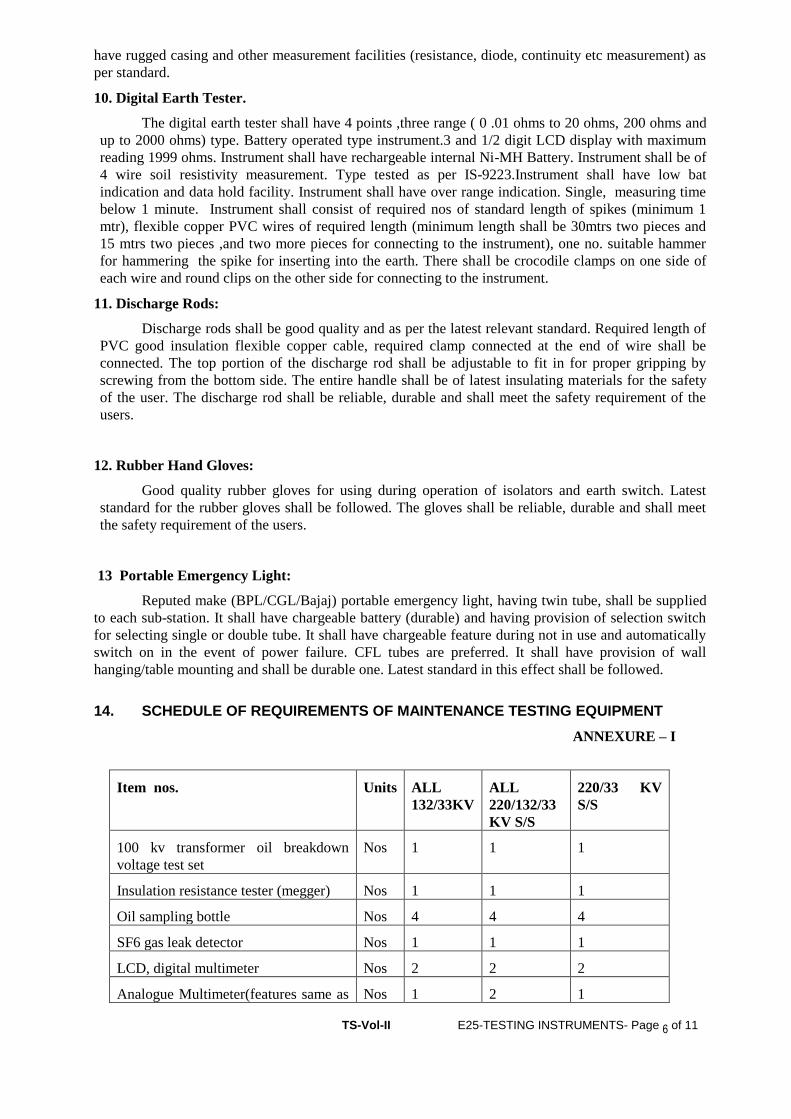
TS-Vol-II E25-TESTING INSTRUMENTS- Page 6 of 11
have rugged casing and other measurement facilities (resistance, diode, continuity etc measurement) as
per standard.
10. Digital Earth Tester.
The digital earth tester shall have 4 points ,three range ( 0 .01 ohms to 20 ohms, 200 ohms and
up to 2000 ohms) type. Battery operated type instrument.3 and 1/2 digit LCD display with maximum
reading 1999 ohms. Instrument shall have rechargeable internal Ni-MH Battery. Instrument shall be of
4 wire soil resistivity measurement. Type tested as per IS-9223.Instrument shall have low bat
indication and data hold facility. Instrument shall have over range indication. Single, measuring time
below 1 minute. Instrument shall consist of required nos of standard length of spikes (minimum 1
mtr), flexible copper PVC wires of required length (minimum length shall be 30mtrs two pieces and
15 mtrs two pieces ,and two more pieces for connecting to the instrument), one no. suitable hammer
for hammering the spike for inserting into the earth. There shall be crocodile clamps on one side of
each wire and round clips on the other side for connecting to the instrument.
11. Discharge Rods:
Discharge rods shall be good quality and as per the latest relevant standard. Required length of
PVC good insulation flexible copper cable, required clamp connected at the end of wire shall be
connected. The top portion of the discharge rod shall be adjustable to fit in for proper gripping by
screwing from the bottom side. The entire handle shall be of latest insulating materials for the safety
of the user. The discharge rod shall be reliable, durable and shall meet the safety requirement of the
users.
12. Rubber Hand Gloves:
Good quality rubber gloves for using during operation of isolators and earth switch. Latest
standard for the rubber gloves shall be followed. The gloves shall be reliable, durable and shall meet
the safety requirement of the users.
13 Portable Emergency Light:
Reputed make (BPL/CGL/Bajaj) portable emergency light, having twin tube, shall be supplied
to each sub-station. It shall have chargeable battery (durable) and having provision of selection switch
for selecting single or double tube. It shall have chargeable feature during not in use and automatically
switch on in the event of power failure. CFL tubes are preferred. It shall have provision of wall
hanging/table mounting and shall be durable one. Latest standard in this effect shall be followed.
14. SCHEDULE OF REQUIREMENTS OF MAINTENANCE TESTING EQUIPMENT
ANNEXURE – I
Item nos. Units ALL
132/33KV
ALL
220/132/33
KV S/S
220/33 KV
S/S
100 kv transformer oil breakdown
voltage test set
Nos 1 1 1
Insulation resistance tester (megger) Nos 1 1 1
Oil sampling bottle Nos 4 4 4
SF6 gas leak detector Nos 1 1 1
LCD, digital multimeter Nos 2 2 2
Analogue Multimeter(features same as Nos 1 2 1

TS-Vol-II E25-TESTING INSTRUMENTS- Page 7 of 11
digital multimeter)
LCD, clamp on meter Nos 2 2 2
Digital earth tester
Nos 1 1 1
Discharge rod as per standard for
carrying out the switch yard
maintenance work
Nos 6 6 6
Rubber gloves of operation of isolators
and earth switch
Pairs 2 2 2
Relay tools kit Sets 1 1 1
Portable emergency light Nos 4 4 4
Latest version desktop PC of reputed
make with all its accessories including
CPU, Monitor, UPS and having all
latest loaded software and also its back
up in shape of CD and separate pen
drive . suitable for loading of software
as recommended by the relay
manufacturer. It includes supply of one
no portable laser printer of reputed
make.
Make of PC and printer: HP/DELL
Set 1 1 1
** The multimeters (both digital and analogue), clamp on meters, earth tester shall preferably of
“Motwane” make. Prior approvals of OPTCL for all the testing equipments are to be taken.
15. OTHER TOOLS AND PLANTS (T&P’S) REQUIREMENT:
(ANNEXURE- II)
Following T&P’s of reputed make are also in the scope of this contract.
Sl
No
Description of Items unit Quantity against Each Package
ALL
132/33 KV
ALL
220/132/33
KV S/S
220/33 KV
S/S
Gopinathpu
r(keonjhar
1 Set of “D” spanner(6mm –
42mm)
Set 1 1 1
2 Set of “Ring” spanner(6mm –
42mm)
Set 1 1 1
3 Socket wrench with
sockets,handles,and other
attachment(6mm-42mm)
Set 1 1 1
4 Insulated cutting plier Nos 2 2 2
5 Insulated nose plier Nos 2 2 2
6 Monkey plier Nos 1 1 1
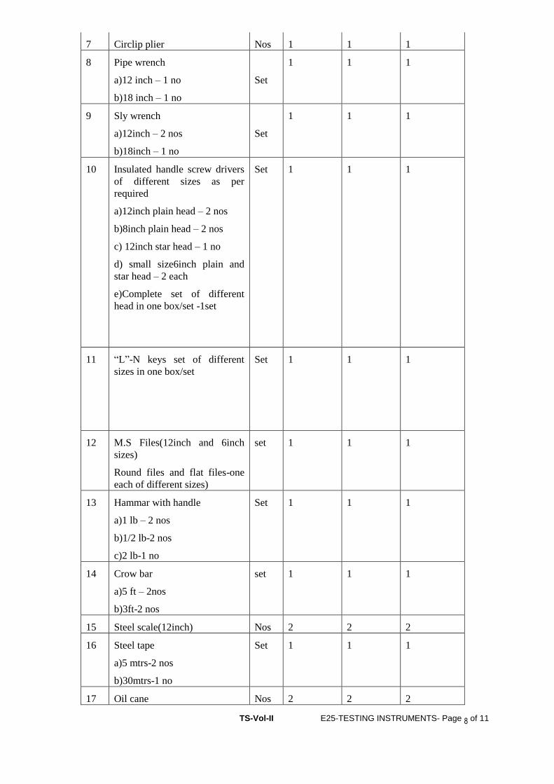
TS-Vol-II E25-TESTING INSTRUMENTS- Page 8 of 11
7 Circlip plier Nos 1 1 1
8 Pipe wrench
a)12 inch – 1 no
b)18 inch – 1 no
Set
1 1 1
9 Sly wrench
a)12inch – 2 nos
b)18inch – 1 no
Set
1 1 1
10 Insulated handle screw drivers
of different sizes as per
required
a)12inch plain head – 2 nos
b)8inch plain head – 2 nos
c) 12inch star head – 1 no
d) small size6inch plain and
star head – 2 each
e)Complete set of different
head in one box/set -1set
Set 1 1 1
11 “L”-N keys set of different
sizes in one box/set
Set 1 1 1
12 M.S Files(12inch and 6inch
sizes)
Round files and flat files-one
each of different sizes)
set 1 1 1
13 Hammar with handle
a)1 lb – 2 nos
b)1/2 lb-2 nos
c)2 lb-1 no
Set 1 1 1
14 Crow bar
a)5 ft – 2nos
b)3ft-2 nos
set 1 1 1
15 Steel scale(12inch) Nos 2 2 2
16 Steel tape
a)5 mtrs-2 nos
b)30mtrs-1 no
Set 1 1 1
17 Oil cane Nos 2 2 2
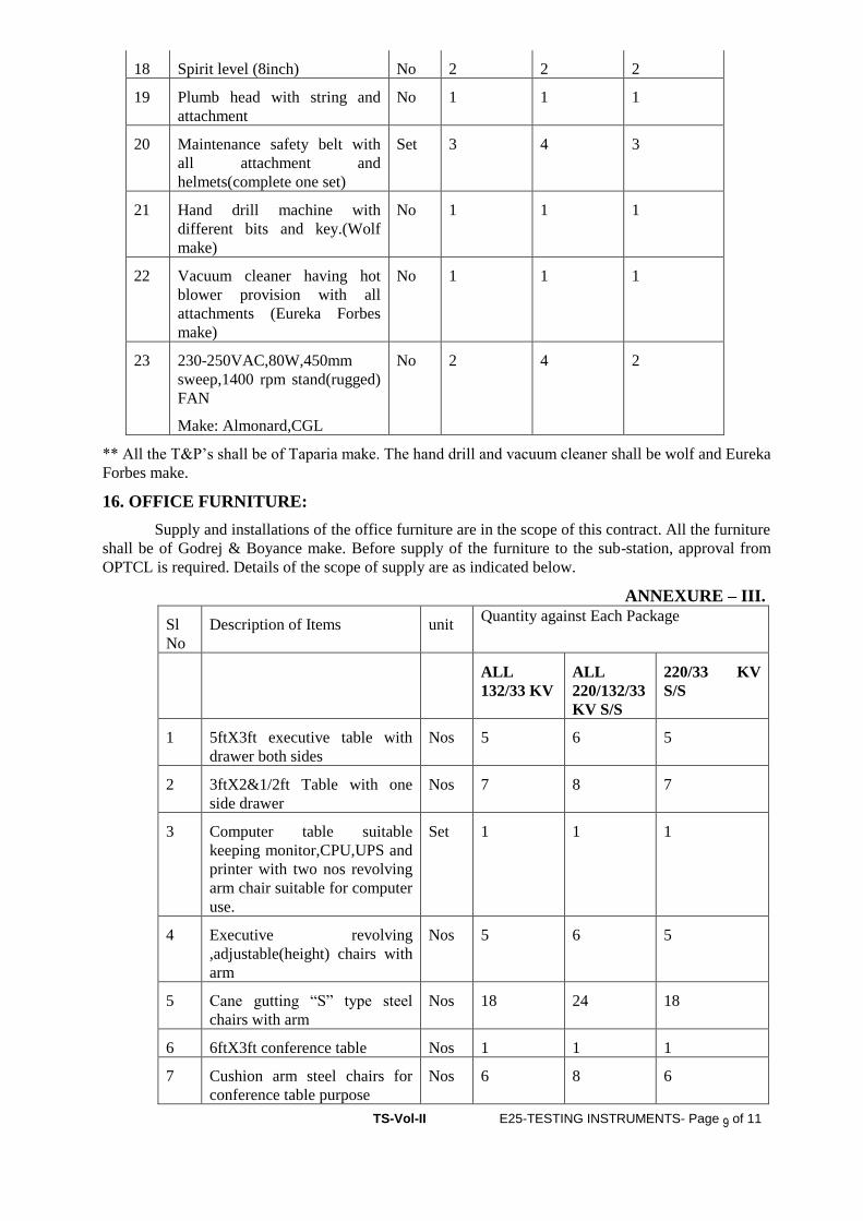
TS-Vol-II E25-TESTING INSTRUMENTS- Page 9 of 11
18 Spirit level (8inch) No 2 2 2
19 Plumb head with string and
attachment
No 1 1 1
20 Maintenance safety belt with
all attachment and
helmets(complete one set)
Set 3 4 3
21 Hand drill machine with
different bits and key.(Wolf
make)
No 1 1 1
22 Vacuum cleaner having hot
blower provision with all
attachments (Eureka Forbes
make)
No 1 1 1
23 230-250VAC,80W,450mm
sweep,1400 rpm stand(rugged)
FAN
Make: Almonard,CGL
No 2 4 2
** All the T&P’s shall be of Taparia make. The hand drill and vacuum cleaner shall be wolf and Eureka
Forbes make.
16. OFFICE FURNITURE:
Supply and installations of the office furniture are in the scope of this contract. All the furniture
shall be of Godrej & Boyance make. Before supply of the furniture to the sub-station, approval from
OPTCL is required. Details of the scope of supply are as indicated below.
ANNEXURE – III.
Sl
No
Description of Items unit Quantity against Each Package
ALL
132/33 KV
ALL
220/132/33
KV S/S
220/33 KV
S/S
1 5ftX3ft executive table with
drawer both sides
Nos 5 6 5
2 3ftX2&1/2ft Table with one
side drawer
Nos 7 8 7
3 Computer table suitable
keeping monitor,CPU,UPS and
printer with two nos revolving
arm chair suitable for computer
use.
Set 1 1 1
4 Executive revolving
,adjustable(height) chairs with
arm
Nos 5 6 5
5 Cane gutting “S” type steel
chairs with arm
Nos 18 24 18
6 6ftX3ft conference table Nos 1 1 1
7 Cushion arm steel chairs for
conference table purpose
Nos 6 8 6
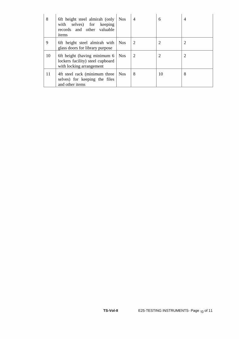
TS-Vol-II E25-TESTING INSTRUMENTS- Page 10 of 11
8 6ft height steel almirah (only
with selves) for keeping
records and other valuable
items
Nos 4 6 4
9 6ft height steel almirah with
glass doors for library purpose
Nos 2 2 2
10 6ft height (having minimum 6
lockers facility) steel cupboard
with locking arrangement
Nos 2 2 2
11 4ft steel rack (minimum three
selves) for keeping the files
and other items
Nos 8 10 8

VOL-II (TS) E26-TRANSMISSION LINE- Page 1 of 105
ODISHA POWER TRANSMISSION CORPORATION LIMITED
TECHNICAL SPECIFICATION
FOR
CONSTRUCTION OF
1)132 KV SC/DC,
2)220 KV SC/DC AND
3)400 KV DC
VOL-II (TS) E26-TRANSMISSION LINE- Page 2 of 105
TRANSMISSION LINES
Nature of work The work covered by this Specification is for 400 kV and/or 220 kV and/or 132 kV
transmission lines as specified herein and in the attached Schedules. The overhead
transmission lines will form part of the OPTCL Transmission System.
General particulars of the system The following are the general particulars governing the design and working of the
complete system of which the Works will form a part —
a) Electrical energy is generated at interconnected power stations as three-phase
current at a frequency of 50 Hz, and transmitted therefrom by means of overhead
lines.
b) The system will be in continuous operation during the varying atmospheric and
climatic conditions occurring at all seasons
1.0 SCOPE-
Construction of 400 KV, 220 KV and 132 KV
As indicated in the Bidding Proposal Sheet & scope of work.
Important: Contractor has to obtain project license from the competent authority
in respect of the mentioned works prior to commencement of the
works. The expenses towards the project license have to be borne by
the contractor.
2.0 SURVEY (detail & check, estimating of quantities & spotting of towers)
2.1.1 General: Preliminary route alignment in respect of the proposed transmission
lines has been fixed by the employer subject to alteration of places due to way
leave or other unavoidable constraints. The Right of way shall be solved by the
contractor and all expenses there of shall be borne by him. However, OPTCL
shall render all helps in co-ordination with law and order department for solving
the same. Forest clearance if any shall be arranged by OPTCL.
2.1.2 Provisional quantities/numbers of different types of towers have been estimated
and indicated in the BOQ Schedule given. However final quantities for work shall be as
determined by the successful bidder, on completion of the detail survey, preparation of
route profile drawing and designing of the different types of towers as elaborated sin
the specification and scope of work.
2.1.2.1 The contractor shall undertake detailed survey on the basis of the tentative
alignment fixed by the employer. The said preliminary alignment may, however,
VOL-II (TS) E26-TRANSMISSION LINE- Page 3 of 105
change in the interest of economy to avoid forest and hazards in work. While surveying
the alternative route the following points shall be taken care by the contractor.
(a) The line is as near as possible to the available roads in the area.
(b) The route is straight and short as far as possible.
© Good farming areas, religious places, forest, civil and defence
installations, aerodromes, public and private premises, ponds, tanks,
lakes, gardens, and plantations are avoided as far as practicable.
(d) The line is far away from telecommunication lines as reasonably
possible. Parallelism with these lines shall be avoided as far as
practicable.
(e) Crossing with permanent objects are minimum but where unavoidable
preferably at right angles.
(f) Difficult and unsafe approaches are avoided.
(g) The survey shall be conducted along the approved alignment only in
accordance with IS: 5613 (Part-II/Section-2), 1985.
(h) For river crossing/ Crossing of Nallas : Taking levels at 25 metre
interval on bank of river and at 50 metre interval at bed of river so far as
to show the true profile of the ground and river bed. The levels may be
taken with respect to the nearest existing towers, pile foundation of
towers, base or railway/road bridge, road culvert etc. The levels shall be
taken at least 100 m. on either side of the crossing alignment. Both
longitudinal and cross sectional shall be drawn preferably to a scale of
1:2000 at horizontal and 1:200 vertical.
After completing the detailed survey, the contractor shall submit the final profile and
tower schedule for final approval of the employer. The final profile and tower
schedule shall incorporate position of all type of towers. To facilitate checking
of the alignment, suitable reference marks shall be provided. For this purpose,
concrete pillars of suitable sizes shall be planted at all angle locations and
suitable wooden/iron pegs shall be driven firmly at the intermediate points. The
contractor shall quote his rate covering these involved jobs.
Only approved sag template shall be used for tower spotting and the final
profiles.
However preliminary survey has been done by OPTCL and any further survey
required shall be done by the contractor.
2.1.2.2 PROFILE PLOTTING AND TOWER SPOTTING
The profile shall be plotted and prepared to the scale 1 in 2,000 for horizontal and 1 in
200 for vertical on squared (mm) paper. If somewhere the difference in levels

VOL-II (TS) E26-TRANSMISSION LINE- Page 4 of 105
be too high, the chart may be broken up according to the requirements. A 10
mm overlap shall be shown on each following sheet. The chart shall progress
from left to right for convenience in handling. The sheet size may be
conveniently chosen.
With the help of sag template, final tower location shall be marked on the
profiles and while locating the tower on survey chart, the following shall be
kept in mind:
(a) The number of consecutive span between the section points shall not exceed 10
in case of straight run on a more or less plain stretch.
(b) Individual span shall be as near as to the normal design ruling span.
In different crossing the contractor shall take into consideration the
prevailing regulations of the respective authorities before finalizing
type and location of the towers. While carrying out survey work, the
contractor has to collect all relevant data, prepare and submit
drawings in requisite number for obtaining clearance from the
PTCC, road, aviation, railways, river and forest authorities.
The contractor shall remain fully responsible for the exact alignment of the line. If after
erection, any tower is found to be out of alignment, the same shall have to be
dismantled and re-erected after corrosion by the contractor at his own cost, risk
and responsibility, including installation of fresh foundation, if belt necessary
by the employer.
After peg marking of the angle tower or tension towers, the contractor shall obtain
approval from the employer and thereafter pegging of suspension type tower
shall be done by the contractor and pegging of all the four legs of each type of
towers at all the locations shall be done.
2.1.2.3 SCHEDULE OF MATERIALS
When the survey is approved, the contractor shall submit to the employer a complete
detail schedule of all materials to be used in the line. Size and length of
conductor etc. are also to be given in the list. This schedule is very essential for
finalizing the quantities of all line material. The contractor shall furnish the
same.
2.1.2.4 CHECK SURVEY
The contractor shall undertake the check survey during execution on the basis of the
alignment profile drawing and tower schedule approved by the employer. If
during check survey necessity arises for minor change in route to eliminate way
leave or other unavoidable constraints, the contractor may change the said
alignment after obtaining prior approval from the employer.
VOL-II (TS) E26-TRANSMISSION LINE- Page 5 of 105
The contractor, while carrying out the check survey, shall peg mark the power position
on ground conforming to the survey charts. In the process, it is necessary to
have the pit centers marks according to the excavating marking charts to be
prepared by the contractor and approved by the employer. The levels up or
down of each pit center with respect to the center of the tower location shall be
noted and recorded for determining the amount of earth work required to meet
the design. At the charting point of the route survey, an angle iron spite shall be
driven firmly into the ground showing a little above the ground level.
2.1.2.5 WAY-LEAVE AND TREE CUTTING
Way-leave permission which may be required by the contractor shall be arranged at his
cost. While submitting final-survey report for approval, proposals for way-leave
right of way shall be submitted by the contractor. Employer may extend help to
get the permission within a reasonable time as mutually agreed upon for which
due notice shall be given by the contractor in such a way so that obtaining
permission from appropriate authority do not hinder the continued and smooth
progress of the work.
The employer shall not be held responsible for any claim on account of damage done
by the contractor or his personnel to trees, crops and other properties.
The contractor shall take necessary precaution to avoid damage to any ripe and partially
grown crops and in the case of unavoidable damage, the employer shall be
informed and necessary compensation shall be paid by the contractor.
All the documents required for application to the statutory authorities must be prepared
by the contractor & submission to the employer for Submission of the
application towards approval of PTCC, Railway Crossing etc. However, the
responsibilities lies with the contractor to get the clearance.
Trimming of tree branches or cutting of a few trees en-route during survey is within the
scope of survey to be done by the contractor. Contractor shall arrange for
necessary way-leave and compensation in this regard. During erection of the
line, compensation for tree cutting, damage caused to crops, actual cutting and
felling of the trees including way-leave permission for such route clearance
shall be arranged by the contractor at his cost. The contractor will identify the
number of trees and detail of obstructions to be removed for erection of the line
and intimate the employer well in advance in case of any help. Other related
works like construction of temporary approach roads, etc. as required, shall be
done by the contractor and the same will lie within the scope of contractor’s
work and such cost shall be considered to be included in the rates quoted by
him.
While quoting the rate for detailed and check survey as per bidding activity schedule,
the contractor shall include all costs involved in different activities described
herein earlier.
2.0 SUB-SOIL INVESTIGATION
VOL-II (TS) E26-TRANSMISSION LINE- Page 6 of 105
To ascertain soil parameters in various stretch inter, the contractor shall carry out sub-
soil investigation through reputed soil consultant as approved by the employer.
2.1 SCOPE OF WORK
The scope of sub-soil investigation covers execution of complete soil exploration for
the transmission line under this contract including boring, drilling, collection of
undisturbed soil sample where possible, otherwise disturbed samples,
conducting laboratory test of soil samples to find out the various parameters as
detailed in this specification and submission of detailed reports in 6 copies
along with specific recommendation regarding suitable type of foundation for
each bore-hole along with recommendation for soil improvement where
necessary.
2.1.1 QUALIFYING REQUIREMENTS OF SOIL CONSULTANTS
The soil consultants shall provide satisfactory evidence concerning the following as and
when asked for.
That, he/they has/have adequate technical knowledge and previous practical experience
in carrying out complete soil investigation jobs in any kind of soil.
That he/they has/have well equipped, modernized soil testing laboratory of his/their
own. If asked for by the employer, the contractor shall arrange inspection of
such laboratory of the soil consultant by the representative of the employer.
If in the opinion of the employer, the soil consultant (proposed by the contractor) is not
well equipped or capable to undertake the sub-soil investigation job relating to
this contract, then such soil consultant shall not be engaged to undertake the job.
In that case, they shall have to engage other agency as will be approved by the
employer.
2.1.3 TEST BORING
The boring shall be done at the major locations/crossing, special towers. However, it is
desirable that there should be at least one sub-soil investigation bore-hole for
the line. Such locations for sub-soil investigation shall be selected and finalized
in consultation with the employer.
The test boring through different layers of all kinds of soil shall have to be carried out
by the contractor through the approved soil consultant as briefed hereunder.
(a) Method of boring, selection of sampling tubes, sampling, recording of boring,
protection, handling, leveling of samples shall be done as specified in IS: 1892/1977, if
any, after obtaining approval from the employer. The contractor/consultant shall furnish
in the soil report in details, the equipment and method of boring actually adopted.
(b) Depth of boring below ground level shall be 15 M. only unless continuous
bedrock is encountered earlier. In case rock is encountered at any depth within 15 M.

VOL-II (TS) E26-TRANSMISSION LINE- Page 7 of 105
adequate study of rock and assessment of strength characteristics shall be done and
recommendation shall be given.
(c) Undisturbed soil samples shall be obtained for the initial 4M depths at every
1.5M interval and at change of strata. After these initial 4M depths, samples shall be
obtained preferably at every 3M or where there is a change of strata, or as advised by
the employer.
(d) In case collection of undisturbed samples becomes difficult/impossible detailed
soil testing on remoulded soil samples is to be considered and reported in the soil
report.
(e) Standard penetration test as per IS: 2131 with latest amendment shall have to be
conducted in different strata and recorded properly.
(f) The ground water table shall be recorded during boring operation and
incorporated in the bore log. If possible, the position of the water table just after
monsoon period be ascertained from local people and indicated in the report.
(g) Plate Load test shall have to be conducted at special tower location.
3.0 LABORATORY TESTS OF SOIL SAMPLES
The method and procedure of testing of soil sample to be followed shall be as per
relevant IS codes. Adequate volume of test samples shall be collected from site.
Ample shall be properly sealed immediately after recovery as specified in
relevant IS code and transported carefully to laboratory for carrying out
necessary laboratory tests to find out the following parameters of every samples.
Data and time of taking of the sample shall be recorded in the test report.
(a) Natural moisture content, Liquid limit, Plastic limit and Plasticity index.
(b) Bulk, dry and buoyant density of soil.
(c) Void ratio (e-long P curve shall be submitted)
(d) Specific gravity.
(e) Grain size distribution (Sieve analysis and hydrometer analysis)
(f) Tri-axial and consolidation tests (consolidation undrained and consolidated
drained as and when application in table, graph and drawing.
(g) Permeability tests
(h) Chemical tests for both water and soil samples at different layers.
(i) Evaluation of safe bearing capacity at different strata for square footings shall
be done for a maximum value of 25-mm. settlements.
(j) At depts. From 3M to 10M be different strata.
(k) Factor of safety shall be considered as 3 for evaluation of safe bearing capacity
of soil.
(l) Unconfined compression test for cohesive soil (=0) if encountered.
3.1 REPORT ON SUB-SOIL INVESTIGATION

VOL-II (TS) E26-TRANSMISSION LINE- Page 8 of 105
The contractor shall make analysis of soil samples and rock cores as collected by him in
the field and approved by the employer as collected by him in the field and
approved by him in the field and approved by the employer as well as field tests
and laboratory tests. A comprehensive report shall have to be prepared by him,
finally incorporating all the data collected in proper tabular forms or otherwise
along with the analysis.
The 3(three) copies of report in the draft form shall be submitted for employer’s
approval. 6(six) copies of final report incorporation employer’s comments, if
any shall be submitted within 3(three) weeks after completion of this work.
Recommendations shall include but not be limited to the following items (a) to (p)
(a) Geological information of the region.
(b) Past observations and historical data, if available, for the area or for other areas
with similar profile or for similar structures in the nearby area.
(c) Procedure of investigations employed and field and field as well as laboratory
test results.
(d) Net safe bearing capacity and settlement computation for different types of
foundations for various widths and depths of tower and building.
(e) Recommendations regarding stability of slopes, during excavations etc.
(f) Selection of foundation types for towers, transformers and buildings etc.
(g) Bore hole and trial pit logs on standard proforma showing the depths, extent of
various soil strata etc.
(h) A set of longitudinal and transverse profiles connecting various boreholes shall
be presented in order to give a clear picture of the site, how the soil/rock strata are
varying vertically and horizontally.
(i) Modulus of sub grade reaction from plate load test for pressure ranging up to 6
kg/cm. The recommended values shall include the effect of size, shape and depth of
foundations.
(j) Deformation modulus from plate load test in various test depth/stratification.
(k) Coefficient of earth pressure at rest.
(l) Depth of ground water table and its effect on foundation design parameters.
(m) Recommendations regarding stability of slopes, during shallow excavation etc.
(n) Whether piles are necessary or not. If piles are necessary, recommendation of
depth, diameter and types of piles to be used.
(o) Recommendations for the type of cement to be used and any treatment to the
underground concrete structure based on the chemical composition of soil and sub-soil
water.
3.1.2 MEASUREMENT OF SOIL RESISTIVITY
For the purpose of grounding design, soil resistance measurement shall be taken in the
locations as stated under clause 1.0 above and based on which the value of soil
resistance shall be derived.
Wenner’s four (4) electrode method shall be used for earth resistance measurement in
accordance with the procedure and the calculation detailed in IS:3043 1987. At
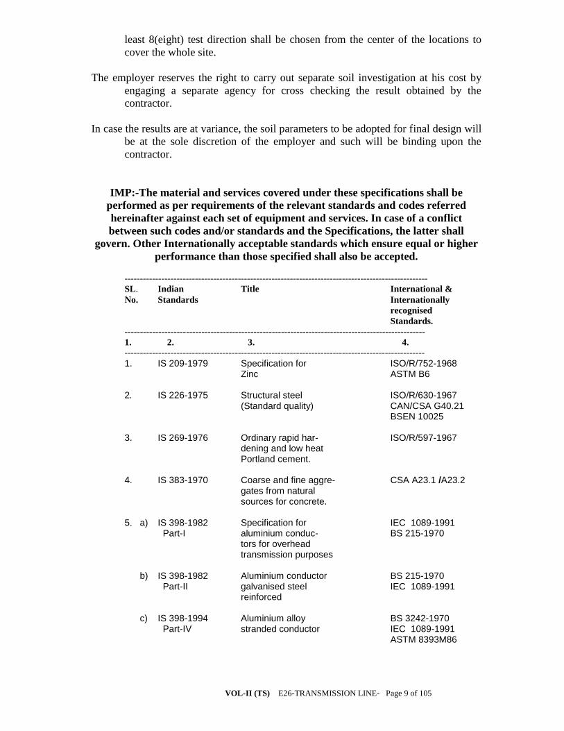
VOL-II (TS) E26-TRANSMISSION LINE- Page 9 of 105
least 8(eight) test direction shall be chosen from the center of the locations to
cover the whole site.
The employer reserves the right to carry out separate soil investigation at his cost by
engaging a separate agency for cross checking the result obtained by the
contractor.
In case the results are at variance, the soil parameters to be adopted for final design will
be at the sole discretion of the employer and such will be binding upon the
contractor.
IMP:-The material and services covered under these specifications shall be
performed as per requirements of the relevant standards and codes referred
hereinafter against each set of equipment and services. In case of a conflict
between such codes and/or standards and the Specifications, the latter shall
govern. Other Internationally acceptable standards which ensure equal or higher
performance than those specified shall also be accepted.
---------------------------------------------------------------------------------------------------
SL. Indian Title International &
No. Standards Internationally
recognised
Standards.
--------------------------------------------------------------------------------------------------
1. 2. 3. 4.
--------------------------------------------------------------------------------------------------
1. IS 209-1979 Specification for ISO/R/752-1968 Zinc ASTM B6 2. IS 226-1975 Structural steel ISO/R/630-1967 (Standard quality) CAN/CSA G40.21 BSEN 10025 3. IS 269-1976 Ordinary rapid har- ISO/R/597-1967 dening and low heat Portland cement. 4. IS 383-1970 Coarse and fine aggre- CSA A23.1 /A23.2 gates from natural sources for concrete. 5. a) IS 398-1982 Specification for IEC 1089-1991 Part-I aluminium conduc- BS 215-1970 tors for overhead transmission purposes b) IS 398-1982 Aluminium conductor BS 215-1970 Part-II galvanised steel IEC 1089-1991 reinforced c) IS 398-1994 Aluminium alloy BS 3242-1970 Part-IV stranded conductor IEC 1089-1991 ASTM 8393M86
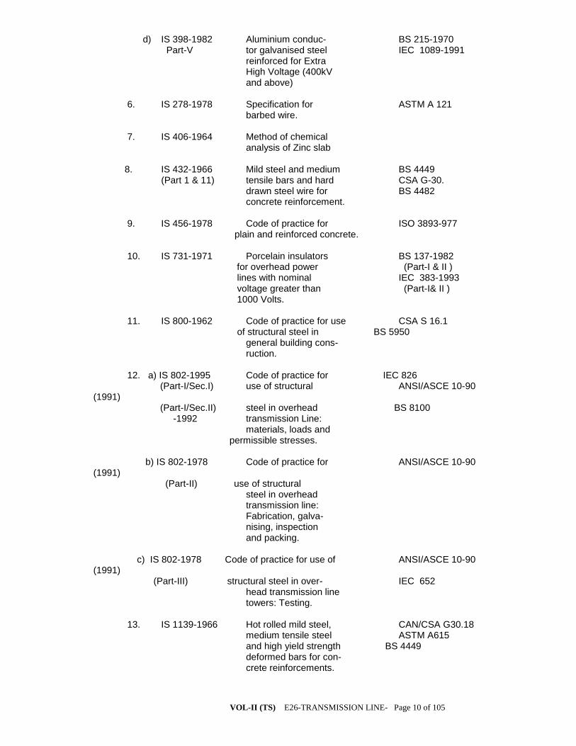
VOL-II (TS) E26-TRANSMISSION LINE- Page 10 of 105
d) IS 398-1982 Aluminium conduc- BS 215-1970 Part-V tor galvanised steel IEC 1089-1991 reinforced for Extra High Voltage (400kV and above) 6. IS 278-1978 Specification for ASTM A 121 barbed wire.
7. IS 406-1964 Method of chemical analysis of Zinc slab 8. IS 432-1966 Mild steel and medium BS 4449 (Part 1 & 11) tensile bars and hard CSA G-30. drawn steel wire for BS 4482 concrete reinforcement. 9. IS 456-1978 Code of practice for ISO 3893-977 plain and reinforced concrete.
10. IS 731-1971 Porcelain insulators BS 137-1982 for overhead power (Part-I & II ) lines with nominal IEC 383-1993 voltage greater than (Part-I& II ) 1000 Volts. 11. IS 800-1962 Code of practice for use CSA S 16.1 of structural steel in BS 5950 general building cons- ruction. 12. a) IS 802-1995 Code of practice for IEC 826 (Part-I/Sec.I) use of structural ANSI/ASCE 10-90 (1991) (Part-I/Sec.II) steel in overhead BS 8100 -1992 transmission Line: materials, loads and permissible stresses. b) IS 802-1978 Code of practice for ANSI/ASCE 10-90 (1991) (Part-II) use of structural steel in overhead transmission line: Fabrication, galva- nising, inspection and packing. c) IS 802-1978 Code of practice for use of ANSI/ASCE 10-90 (1991) (Part-III) structural steel in over- IEC 652 head transmission line towers: Testing. 13. IS 1139-1966 Hot rolled mild steel, CAN/CSA G30.18 medium tensile steel ASTM A615 and high yield strength BS 4449 deformed bars for con- crete reinforcements.
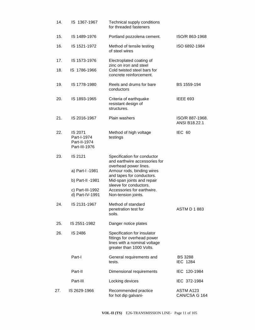
VOL-II (TS) E26-TRANSMISSION LINE- Page 11 of 105
14. IS 1367-1967 Technical supply conditions for threaded fasteners 15. IS 1489-1976 Portland pozzolena cement. ISO/R 863-1968 16. IS 1521-1972 Method of tensile testing ISO 6892-1984 of steel wires 17. IS 1573-1976 Electroplated coating of zinc on iron and steel 18. IS 1786-1966 Cold twisted steel bars for concrete reinforcement. 19. IS 1778-1980 Reels and drums for bare BS 1559-194 conductors 20. IS 1893-1965 Criteria of earthquake IEEE 693 resistant design of structures. 21. IS 2016-1967 Plain washers ISO/R 887-1968. ANSI B18.22.1 22. IS 2071 Method of high voltage IEC 60 Part-I-1974 testings Part-II-1974 Part-III-1976 23. IS 2121 Specification for conductor and earthwire accessories for overhead power lines. a) Part-I -1981 Armour rods, binding wires and tapes for conductors. b) Part-II -1981 Mid-span joints and repair sleeve for conductors. c) Part-III-1992 Accessories for earthwire. d) Part-IV-1991 Non-tension joints. 24. IS 2131-1967 Method of standard penetration test for ASTM D 1 883 soils. 25. IS 2551-1982 Danger notice plates 26. IS 2486 Specification for insulator fittings for overhead power lines with a nominal voltage greater than 1000 Volts. Part-I General requirements and BS 3288 tests. IEC 1284 Part-II Dimensional requirements IEC 120-1984 Part-III Locking devices IEC 372-1984 27. IS 2629-1966 Recommended practice ASTM A123 for hot dip galvani- CAN/CSA G 164

VOL-II (TS) E26-TRANSMISSION LINE- Page 12 of 105
sing of iron and steel. BS 729 28. IS 2633-1972 Method of testing ASTM A123 uniformity of coating CAN/CSA G164 of zinc coated articles. 29. IS 3043-1972 Code of practice for earthing(with amend- ment No.1 and 2). 30. IS 3063-1972 Single coil rectangular DIN 127-1970 section spring washers for bolts nuts, screws. 31. IS 3188-1965 Dimensions for disc IEC 305-1978 insulators. 32. IS 4091-1967 Code of practice for ASCE/IEEE 691 design and construction of foundation for trans- mission line towers and poles. 33. IS 4826-1979 Galvanised coating on IEC 888-1987 round steel wires. BS 443-1982 34. IS 5358-1969 Hot dip galvanised coat- CAN/CSA G 164 ings on fasteners. ASTM A153 35. IS 5613 Code of practice for ANSI/ASCE 10-90(1991) (Part-II/Sec-1) design, installation and -1985 maintenance of overhead (Part-III/Sec.1) power lines (Section-l: -1989 Designs) 36. IS 5613 Code of practice for (Part-II/Sec-2) design, installation and -1985 maintenance of overhead (Part-III/Sec.2) power lines (Section 2: -1989 Installation and maintenance) 37. IS 6610-1972 Specification for heavy washers for steel structures. 38. IS 6639-1972 Hexagonal bolts for steel ISO/R 272-1968 structure. ASTM A394 CSA B33.4 39. IS 6745-1972 Methods for determination ASTM A90 of weight of zinc coating ISO 1460 of zinc coated iron and steel articles. 40. IS 8263-1976 Method of radio interference IEC 437-1973 tests on high voltage insulator NEMA 107-1964 41. IS 8269-1976 Method of switching impulse IEC 506-1975 tests on HV insulators.
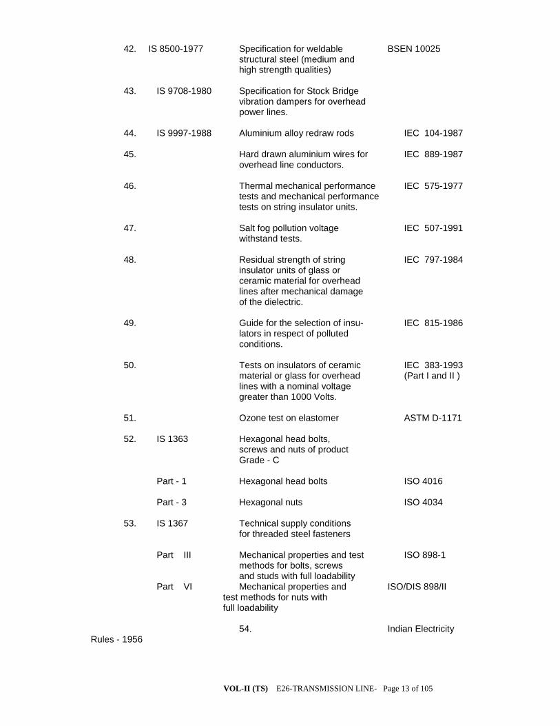
VOL-II (TS) E26-TRANSMISSION LINE- Page 13 of 105
42. IS 8500-1977 Specification for weldable BSEN 10025 structural steel (medium and high strength qualities) 43. IS 9708-1980 Specification for Stock Bridge vibration dampers for overhead power lines. 44. IS 9997-1988 Aluminium alloy redraw rods IEC 104-1987 45. Hard drawn aluminium wires for IEC 889-1987 overhead line conductors. 46. Thermal mechanical performance IEC 575-1977 tests and mechanical performance tests on string insulator units. 47. Salt fog pollution voltage IEC 507-1991 withstand tests. 48. Residual strength of string IEC 797-1984 insulator units of glass or ceramic material for overhead lines after mechanical damage of the dielectric. 49. Guide for the selection of insu- IEC 815-1986 lators in respect of polluted conditions. 50. Tests on insulators of ceramic IEC 383-1993 material or glass for overhead (Part I and II ) lines with a nominal voltage greater than 1000 Volts. 51. Ozone test on elastomer ASTM D-1171 52. IS 1363 Hexagonal head bolts, screws and nuts of product Grade - C Part - 1 Hexagonal head bolts ISO 4016 Part - 3 Hexagonal nuts ISO 4034 53. IS 1367 Technical supply conditions for threaded steel fasteners Part III Mechanical properties and test ISO 898-1 methods for bolts, screws and studs with full loadability Part VI Mechanical properties and ISO/DIS 898/II test methods for nuts with full loadability 54. Indian Electricity Rules - 1956
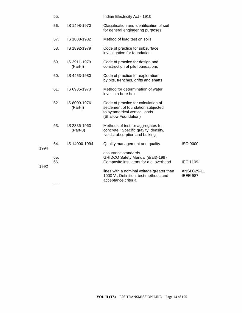
VOL-II (TS) E26-TRANSMISSION LINE- Page 14 of 105
55. Indian Electricity Act - 1910 56. IS 1498-1970 Classification and identification of soil for general engineering purposes 57. IS 1888-1982 Method of load test on soils 58. IS 1892-1979 Code of practice for subsurface investigation for foundation 59. IS 2911-1979 Code of practice for design and (Part-I) construction of pile foundations 60. IS 4453-1980 Code of practice for exploration by pits, trenches, drifts and shafts 61. IS 6935-1973 Method for determination of water level in a bore hole 62. IS 8009-1976 Code of practice for calculation of (Part-I) settlement of foundation subjected to symmetrical vertical loads (Shallow Foundation) 63. IS 2386-1963 Methods of test for aggregates for (Part-3) concrete : Specific gravity, density, voids, absorption and bulking 64. IS 14000-1994 Quality management and quality ISO 9000-1994 assurance standards 65. GRIDCO Safety Manual (draft)-1997 66. Composite insulators for a.c. overhead IEC 1109-1992 lines with a nominal voltage greater than ANSI C29-11 1000 V : Definition, test methods and IEEE 987 acceptance criteria ----

VOL-II (TS) E26-TRANSMISSION LINE- Page 15 of 105
SUPPLY OF TOWER STRUCTURES FOR THE
TRANSMISSION LINES 1.0 SCOPE
1.1 This specification provides for design, proto fabrication, galvanizing and
delivery FOR (destination) of transmission line towers including super-structure stubs,
tower extensions, stub-templates, tower accessories (Hangers, U-bolts, bird guards,
anti-climbing devices), bolts and nuts, step bolts, flat and spring washers etc. as
described hereinafter in this volume.
THE PRELIMINARY SURVEY WORK HAS ALREADY DONE AND THE
FOLLOWING TOWERS HAVE BEEN DECIDED.
The contractor shall design the tower foundation and the concreting shall
be done by M-20 grade concrete.
a) Wind effects:
Tower shall be designed for reliability Level-I, Terrain category-I &
Wind Zone-V Design wind pressure on towers, conductors, earth wire and
insulator string in the range of 30.45 mt. And above 45 mt. Height shall be
computed as per IS-802(Part/Sec-I) 1995 Bidder shall furnish the maximum
wind pressure adopted in their design against each component mentioned above.
b) Design Temperatures:
The following temperature range for the power conductor and ground wires
shall be adopted for the line design:
(i) Minimum temperature: 5 deg. C
(ii) Everyday temperature of conductor: 32 deg. C
(iii) Maximum temperature of :
a) Conductor:ACSR 75 deg. C for ACSR
Moose/Zebra/Panther 90 deg. C for AAAC.
(**Double Moose conductor in 400 KV system)
b) Ground wire exposed to sun. 53 deg. C
The above values are subject to latest revision if any made in IS-802 (part-I/Sec-I) 1995
Maximum Tension:
Maximum tension shall be based on either:
a) at 5 deg. C with 2/3rd
. full wind pressure or Conform to IS 802-1995
b) at 32 deg. C with full wind pressure whichever Part-I/Sec-I-Clause No.10.3
is more stringent.
Factors of Safety & Span details:
Factor of Safety: Should conform to IS-802 Part-I-1995
Normal span: The normal span of the line shall be 350 meters of 220KV and
320 meters for 132 KV.
Wind & Weight Span: The wind and weight span to be adopted in the design of the
structures shall be as follows:
(i) Wind span: The wind span is the sum of the two half spans adjacent to the
support under consideration. In case of towers located on a perfectly horizontal terrain,
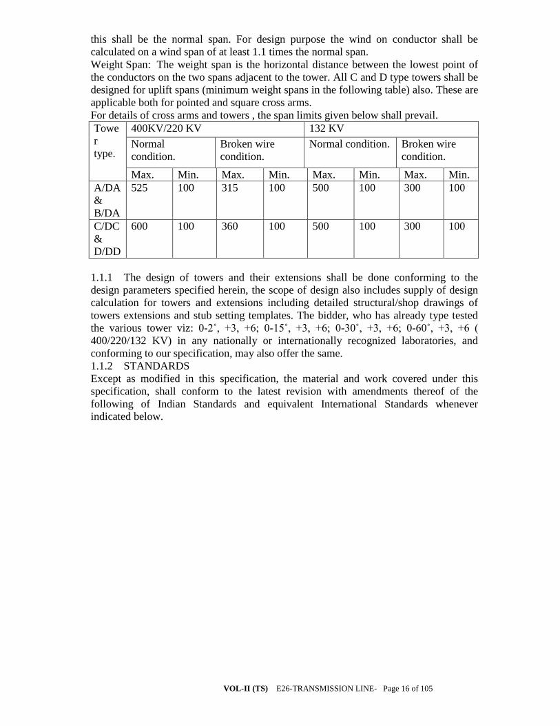
VOL-II (TS) E26-TRANSMISSION LINE- Page 16 of 105
this shall be the normal span. For design purpose the wind on conductor shall be
calculated on a wind span of at least 1.1 times the normal span.
Weight Span: The weight span is the horizontal distance between the lowest point of
the conductors on the two spans adjacent to the tower. All C and D type towers shall be
designed for uplift spans (minimum weight spans in the following table) also. These are
applicable both for pointed and square cross arms.
For details of cross arms and towers , the span limits given below shall prevail.
Towe
r
type.
400KV/220 KV 132 KV
Normal
condition.
Broken wire
condition.
Normal condition. Broken wire
condition.
Max. Min. Max. Min. Max. Min. Max. Min.
A/DA
&
B/DA
525 100 315 100 500 100 300 100
C/DC
&
D/DD
600 100 360 100 500 100 300 100
1.1.1 The design of towers and their extensions shall be done conforming to the
design parameters specified herein, the scope of design also includes supply of design
calculation for towers and extensions including detailed structural/shop drawings of
towers extensions and stub setting templates. The bidder, who has already type tested
the various tower viz: 0-2˚, +3, +6; 0-15˚, +3, +6; 0-30˚, +3, +6; 0-60˚, +3, +6 (
400/220/132 KV) in any nationally or internationally recognized laboratories, and
conforming to our specification, may also offer the same.
1.1.2 STANDARDS
Except as modified in this specification, the material and work covered under this
specification, shall conform to the latest revision with amendments thereof of the
following of Indian Standards and equivalent International Standards whenever
indicated below.

VOL-II (TS) E26-TRANSMISSION LINE- Page 17 of 105
Sl.
No
.
Bureau of Indian
standards (BIS)
Title International &
Internationally
recognized
standard
1. IS:209 Specification for Zinc ISO/R/752
2. IS: 2062 Structural steel (Standard quality) ISO/R/660
3. IS: 432 Mild steel and medium tensile bars
and for concrete reinforcement
BS-785CSA-G-30
4. IS: 802 Code of practice for use of structural
steel in overhead transmission line
Part-I/Section-I & Section2:
Load and permissible stresses
Part-II: Fabrication Galvanizing
Inspection and Packing
PART-III: TESTING
5. IS: 1367 Technical supply conditions for
threaded fasteners
6. IS: 1893 Criteria of Earthquake resistant
design structures
7. IS: 2016 Plain washers ISO/R/987
8. IS: 2551 Danger Notice Plates
9. IS: 2629 Recommended practice for hot dip
galvanizing of iron and steel
10. IS: 2633 Method of testing uniformity of
casting of zinc coated articles
11. IS: 3063 Single coil rectangular section
spring washers for bolts, bolts,
screws
DIN-127
12. IS: 5358 Hot dip galvanized coatings on
fasteners
13. IS:5613
Part-1 & 2
Of Section-I
Code of Practices for design,
installation & maintenance of
overhead power line

VOL-II (TS) E26-TRANSMISSION LINE- Page 18 of 105
14. IS: 6610 Specification for heavy washers for
stell structures.
15. IS: 6745 Methods of determination of weight
of zinc coating of zinc coated iron
and steel articles.
16. IS: 12427 Hexagonal bolts for steel structures
17. INDIAN ELECTRICITY RULES
1956
18. Publication for Regulation for
electrical crossing or railway tracks
1.1.3 The standards mentioned above are available from
Reference/ Name and Address from which
Abbreviation the Standards are available
IS BUREAU OF INDIAN STANDARDS
Manak Bhavan,
9, Bahadur Shah Zafar Marg,
NEW DELHI(India)
ISO INTERNATIONAL ORGANISATION FOR
STANDARDISATION,
Danish Board Standardisation,
Danish Standardisening Street,
Aurehoegbvej-12,
DK-2900, Helleprup, DENMARK
CSA CANADIAN STANDARD ASSOCIATION
178, Rexdale Boulevard, Rexdale,
Ontario, CANADA
M9W IR
BS BRITISH STANDARDS
British Standard Institution,
101, Pentonvile Road,
N-19-ND-UK
DIN DEUTSCHES INSTITUTE FIIR NOR
Gurggrafenstrasse 5-10
Post Fach 1107
D-1000, Berlin – 30
INDIAN
ELECTRICITY
RULES
KITAB MAHAL
1956, REGULATION
FOR
Baba Kharak Singh Marg,
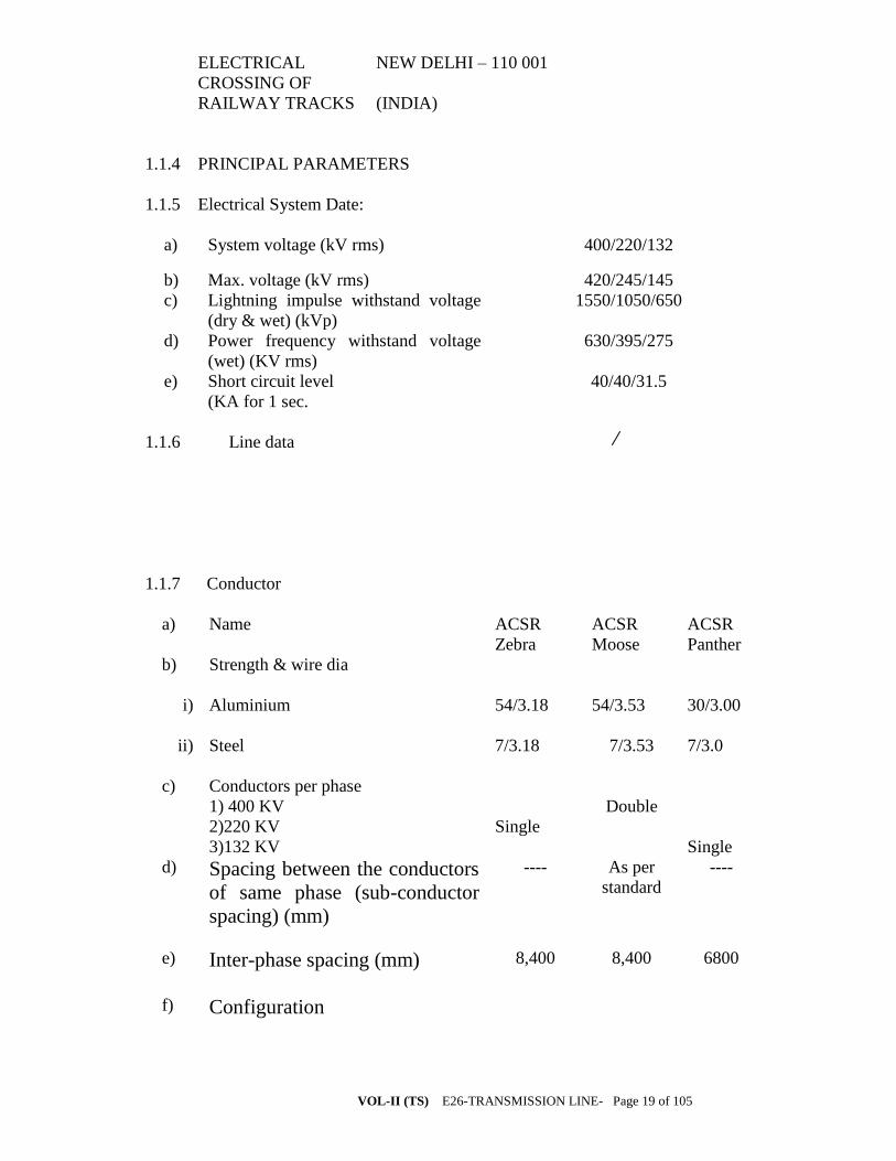
VOL-II (TS) E26-TRANSMISSION LINE- Page 19 of 105
ELECTRICAL
CROSSING OF
NEW DELHI – 110 001
RAILWAY TRACKS (INDIA)
1.1.4 PRINCIPAL PARAMETERS
1.1.5 Electrical System Date:
a) System voltage (kV rms) 400/220/132
b) Max. voltage (kV rms) 420/245/145
c) Lightning impulse withstand voltage
(dry & wet) (kVp)
1550/1050/650
d) Power frequency withstand voltage
(wet) (KV rms)
630/395/275
e) Short circuit level
(KA for 1 sec.
40/40/31.5
1.1.6 Line data
1.1.7 Conductor
a) Name ACSR
Zebra
ACSR
Moose
ACSR
Panther
b) Strength & wire dia
i) Aluminium 54/3.18 54/3.53 30/3.00
ii) Steel 7/3.18 7/3.53 7/3.0
c) Conductors per phase
1) 400 KV
2)220 KV
3)132 KV
Single
Double
Single
d) Spacing between the conductors
of same phase (sub-conductor
spacing) (mm)
---- As per
standard
----
e) Inter-phase spacing (mm)
8,400 8,400 6800
f) Configuration
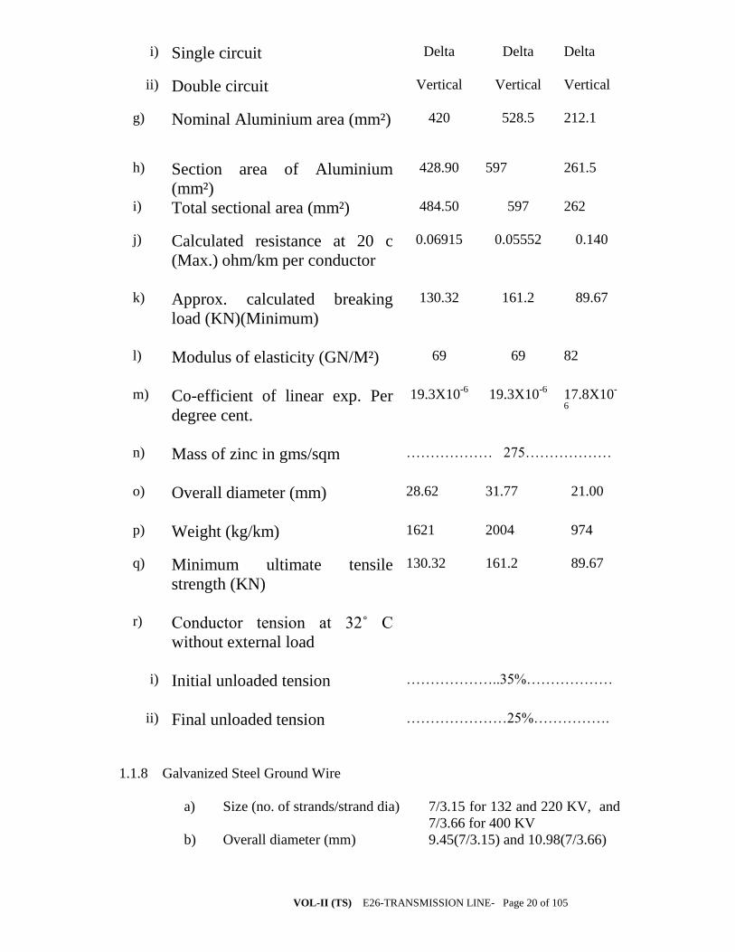
VOL-II (TS) E26-TRANSMISSION LINE- Page 20 of 105
i) Single circuit Delta Delta Delta
ii) Double circuit Vertical Vertical Vertical
g) Nominal Aluminium area (mm²) 420 528.5
212.1
h) Section area of Aluminium
(mm²)
428.90 597
261.5
i) Total sectional area (mm²) 484.50 597 262
j) Calculated resistance at 20 c
(Max.) ohm/km per conductor
0.06915 0.05552 0.140
k) Approx. calculated breaking
load (KN)(Minimum)
130.32 161.2 89.67
l) Modulus of elasticity (GN/M²)
69 69 82
m) Co-efficient of linear exp. Per
degree cent.
19.3X10⁻⁶
19.3X10⁻⁶
17.8X10-
6
n) Mass of zinc in gms/sqm
……………… 275………………
o) Overall diameter (mm)
28.62 31.77 21.00
p) Weight (kg/km) 1621 2004 974
q) Minimum ultimate tensile
strength (KN)
130.32 161.2 89.67
r) Conductor tension at 32˚ C
without external load
i) Initial unloaded tension
………………..35%………………
ii) Final unloaded tension
…………………25%…………….
1.1.8 Galvanized Steel Ground Wire
a) Size (no. of strands/strand dia) 7/3.15 for 132 and 220 KV, and
7/3.66 for 400 KV
b) Overall diameter (mm) 9.45(7/3.15) and 10.98(7/3.66)
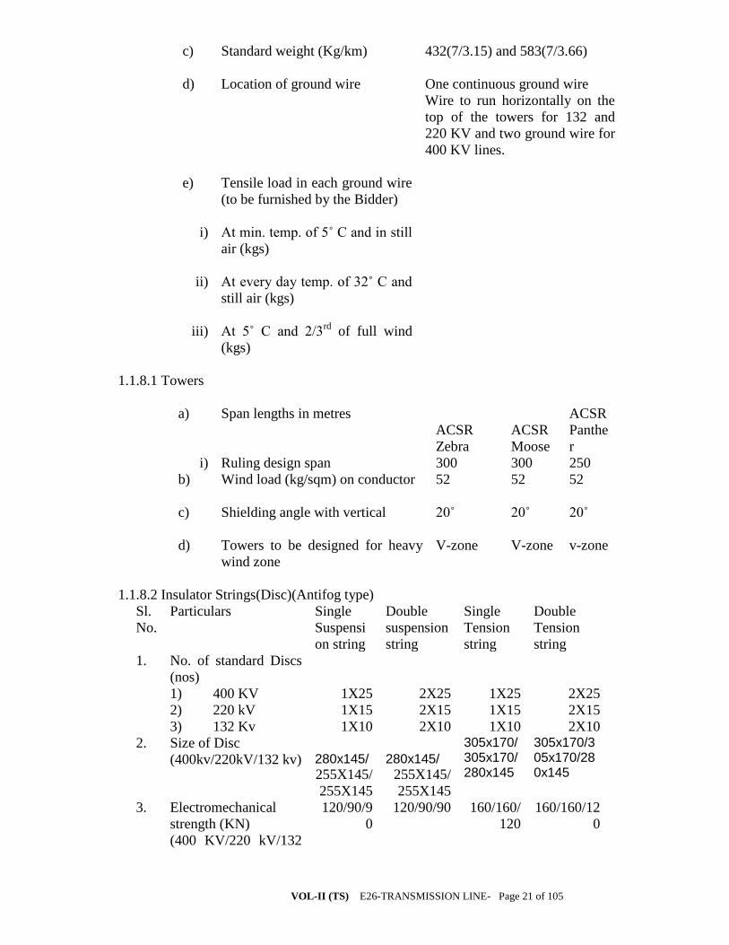
VOL-II (TS) E26-TRANSMISSION LINE- Page 21 of 105
c) Standard weight (Kg/km) 432(7/3.15) and 583(7/3.66)
d) Location of ground wire One continuous ground wire
Wire to run horizontally on the
top of the towers for 132 and
220 KV and two ground wire for
400 KV lines.
e) Tensile load in each ground wire
(to be furnished by the Bidder)
i) At min. temp. of 5˚ C and in still
air (kgs)
ii) At every day temp. of 32˚ C and
still air (kgs)
iii) At 5˚ C and 2/3rd
of full wind
(kgs)
1.1.8.1 Towers
a) Span lengths in metres
ACSR
Zebra
ACSR
Moose
ACSR
Panthe
r
i) Ruling design span 300 300 250
b) Wind load (kg/sqm) on conductor
52 52 52
c) Shielding angle with vertical
20˚ 20˚ 20˚
d) Towers to be designed for heavy
wind zone
V-zone V-zone v-zone
1.1.8.2 Insulator Strings(Disc)(Antifog type)
Sl.
No.
Particulars Single
Suspensi
on string
Double
suspension
string
Single
Tension
string
Double
Tension
string
1. No. of standard Discs
(nos)
1) 400 KV
2) 220 kV
3) 132 Kv
1X25
1X15
1X10
2X25
2X15
2X10
1X25
1X15
1X10
2X25
2X15
2X10
2. Size of Disc
(400kv/220kV/132 kv)
280x145/
255X145/
255X145
280x145/
255X145/
255X145
305x170/305x170/280x145
305x170/305x170/280x145
3. Electromechanical
strength (KN)
(400 KV/220 kV/132
120/90/9
0
120/90/90 160/160/
120
160/160/12
0
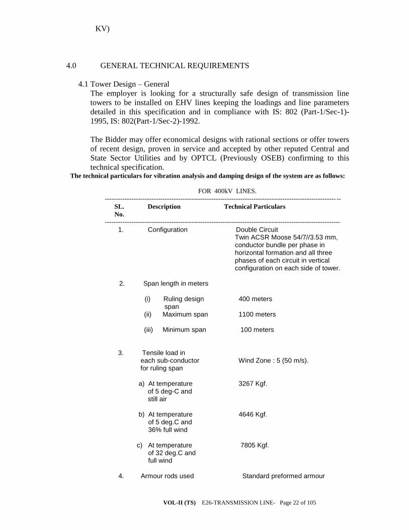
VOL-II (TS) E26-TRANSMISSION LINE- Page 22 of 105
KV)
4.0 GENERAL TECHNICAL REQUIREMENTS
4.1 Tower Design – General
The employer is looking for a structurally safe design of transmission line
towers to be installed on EHV lines keeping the loadings and line parameters
detailed in this specification and in compliance with IS: 802 (Part-1/Sec-1)-
1995, IS: 802(Part-1/Sec-2)-1992.
The Bidder may offer economical designs with rational sections or offer towers
of recent design, proven in service and accepted by other reputed Central and
State Sector Utilities and by OPTCL (Previously OSEB) confirming to this
technical specification. The technical particulars for vibration analysis and damping design of the system are as follows:
FOR 400kV LINES.
-------------------------------------------------------------------------------------------------------- --
SL. Description Technical Particulars
No.
----------------------------------------------------------------------------------------------------------
1. Configuration Double Circuit Twin ACSR Moose 54/7//3.53 mm, conductor bundle per phase in horizontal formation and all three phases of each circuit in vertical configuration on each side of tower.
2. Span length in meters
(i) Ruling design 400 meters
span (ii) Maximum span 1100 meters (iii) Minimum span 100 meters
3. Tensile load in each sub-conductor Wind Zone : 5 (50 m/s). for ruling span a) At temperature 3267 Kgf. of 5 deg-C and still air b) At temperature 4646 Kgf. of 5 deg.C and 36% full wind c) At temperature 7805 Kgf. of 32 deg.C and full wind 4. Armour rods used Standard preformed armour
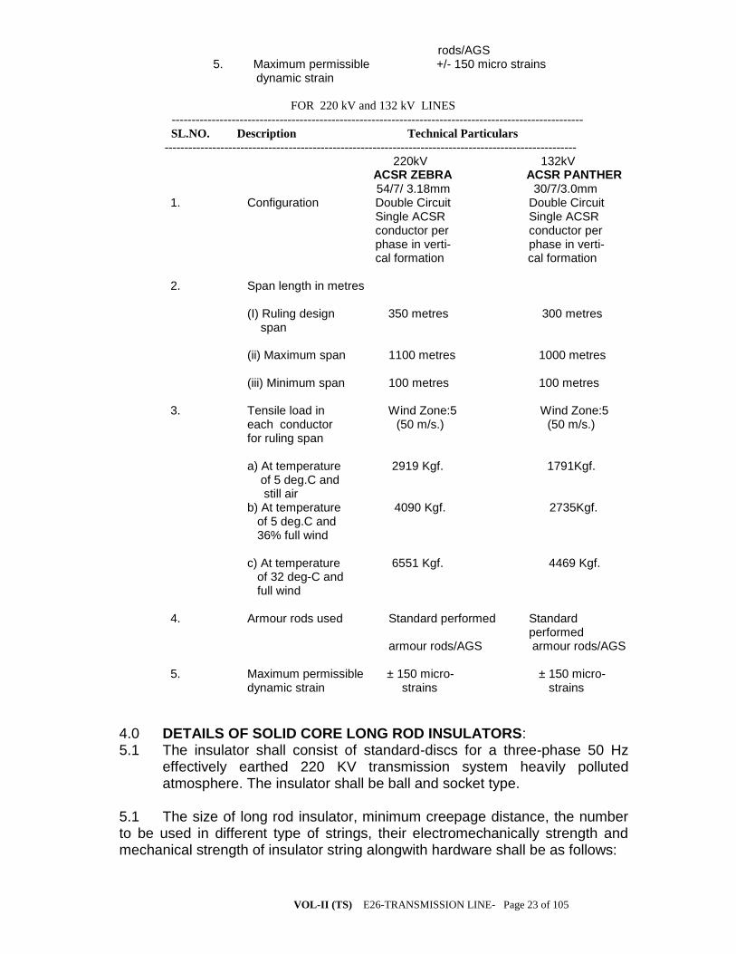
VOL-II (TS) E26-TRANSMISSION LINE- Page 23 of 105
rods/AGS 5. Maximum permissible +/- 150 micro strains dynamic strain
FOR 220 kV and 132 kV LINES
-------------------------------------------------------------------------------------------------------
SL.NO. Description Technical Particulars
-------------------------------------------------------------------------------------------------------
220kV 132kV ACSR ZEBRA ACSR PANTHER 54/7/ 3.18mm 30/7/3.0mm
1. Configuration Double Circuit Double Circuit Single ACSR Single ACSR conductor per conductor per phase in verti- phase in verti-
cal formation cal formation
2. Span length in metres (I) Ruling design 350 metres 300 metres span (ii) Maximum span 1100 metres 1000 metres (iii) Minimum span 100 metres 100 metres
3. Tensile load in Wind Zone:5 Wind Zone:5 each conductor (50 m/s.) (50 m/s.) for ruling span a) At temperature 2919 Kgf. 1791Kgf. of 5 deg.C and still air b) At temperature 4090 Kgf. 2735Kgf. of 5 deg.C and 36% full wind c) At temperature 6551 Kgf. 4469 Kgf. of 32 deg-C and full wind 4. Armour rods used Standard performed Standard performed armour rods/AGS armour rods/AGS 5. Maximum permissible ± 150 micro- ± 150 micro- dynamic strain strains strains
4.0 DETAILS OF SOLID CORE LONG ROD INSULATORS: 5.1 The insulator shall consist of standard-discs for a three-phase 50 Hz
effectively earthed 220 KV transmission system heavily polluted atmosphere. The insulator shall be ball and socket type.
5.1 The size of long rod insulator, minimum creepage distance, the number to be used in different type of strings, their electromechanically strength and mechanical strength of insulator string alongwith hardware shall be as follows:

VOL-II (TS) E26-TRANSMISSION LINE- Page 24 of 105
Sl. No.
Type of string.
Size of long rod insulator (mm)/(Unit) 132/220 KV
Minimum creepage distance (mm) 132/220 KV
No.of unit 132/220 KV)
Electromechanical strength of insulator (KN) 132/220 KV)
1.
Single suspension
200X 1305
/210X2030
4000 /
6125
'1/2 90 KN
2.
Double suspension
-do- -do- '2/4 90 KN
3.
Single tension.
205 X 1450 /
215X2550
4300/7130 '1/2 120 KN/160 KN
4.
Double Tension.
-do- -do- '2/4 120 KN/160 KN
5.0 SPECIFICATION DRAWINGS: 6.1 A list of specification drawings in respect of the long rod insulators
indicated above is given at Annexure-II. These specification drawings are attached herewith for information and guidance of the bidder only. The drawings to be furnished by the supplier shall be as per his own design and manufacture and shall be distinct and separate from these specification drawings.
6.0 GENERAL TECHNICAL REQUIREMENT: 7.1 PORCELAIN:
The porcelain used in the manufacture of the shell shall be ivory white, nonporous of high dielectric, mechanical and thermal strength free from internal stress blisters and thermal strength from internal stresses blisters, laminations, voids, foreign matter. Imperfections or other defects, which might render it in any way unsuitable for insulator shells. Porcelain shall remain unaffected by climatic conditions, ozone, acid alkalis, and zinc of dust. The manufacturing shall be by the wet process and impervious character obtained by through vetrification.
7.2 PORCELAIN GLAZE:
Surfaces to come in contact with cement shall be made rough by stand glazing. All other exposed surfaces shall be glazed with ceramic materials having the same temperature coefficient of expansion as that of the insulator shell. The thickness of the glaze shall be uniform throughout and the colour of the glaze shall be brown. The glaze shall have a visible luster and smooth on surface and be capable of satisfactory performance under extreme tropical climatic weather conditions and prevent ageing of the porcelain. The glaze shall remain under compression on the porcelain body throughout the working temperature range.
7.3 METAL PARTS:
VOL-II (TS) E26-TRANSMISSION LINE- Page 25 of 105
7.3.1 Cap and Ball pins: Twin Ball pins shall be made with drop forged steel and caps with malleable cast iron. They shall be in one single piece and duly hot dip g galvanized. They shall not contain parts or pieces joined together, welded, shrink fitted or by any other process from more than one piece of material. The pins shall be of high tensile steel, drop forged and heat malleable cast iron and annealed. Galvanizing shall be by the hot dip process with a heavy coating of zinc of very high purity with minimum of 6 dips. The bidder shall specify the grade, composition and mechanical properties of steel used for caps and pins.
7.3.2 SECURITY CLIPS: The security clips shall be made of phosphor bronze or of stainless steel. 7.4 FILLER MATERIAL: Cement to be used as a filler material shall be quick setting, for curing Portland cement. It shall not cause fracture by expansion or loosening by contraction. Cement shall not react chemically with metal parts in contract with it and its thickness shall be as small and as uniform as possible. 7.0 MATERIAL DESIGN AND WORKMANSHIP: 8.1 GENERAL: i) All raw materials to be used in the manufacture of these insulators shall be subject to strict raw materials quality control and to stage testing quality control during manufacturing stage to ensure the quality of the final end product. Manufacturing shall conform to the best engineering practices adopted in the field of extra high voltage transmission. Bidders shall therefore offer insulators as are guaranteed by them for satisfactory performance on Transmission lines. ii) The design, manufacturing process and material control at various stages be such as to give maximum working load, highest mobility, best resistance to corrosion good finish, elimination of sharp edges and corners to limit corona and radio interference voltage 8.2 INSULATOR SHELL:
The design of the insulator shell shall be such that stresses due to expansion and contraction in any part of the insulator shall not lead to deterioration. Shells with cracks shall be eliminated by temperature cycle test followed by temperature cycle test followed by mallet test. Shells shall be dried under controlled conditions of humidity and temperature.
8.3 METAL PARTS: a) The twin ball pin and cap shall be designed to transmit the mechanical stresses to the shell by compression and develop uniform mechanical strength in the insulator. The cap shall be circular with the inner and outer surfaces concentric and of such design that it will not yield or distort under loaded conditions. The head portion of the insulator or is under tension the stresses are uniformly distributed over the pinhole portion of the shell. The pinball shall
VOL-II (TS) E26-TRANSMISSION LINE- Page 26 of 105
move freely in the cap socket either during assembly of a string or during erection of a string or when a string is placed in position. b) Metal caps shall be free from cracks, seams, shrinks, air holes, blowholes and rough edges. All metal surfaces shall be perfectly smooth with no projecting parts or irregularities which may cause corona. All load bearing surfaces shall be smooth and uniform so as to distribute the loading stresses uniformly. Pins shall not show any macroscopically visible cracks, insulations and voids. 8.4 GALVANIZING:
All ferrous parts shall be hot dip galvanized six times in accordance with IS: 2629. The zinc to be used for galvanizing shall conform to grade Zn 99.5 as per IS: 209. The zinc coating shall be uniform, smoothly adherent, reasonably light, continuous and free from impurities such as flux ash, rust stains, bulky white deposits and blisters. Before ball fittings are galvanized, all die flashing on the shank and on the bearing surface of the ball shall be carefully removed without reducing the designed dimensional requirements.
8.4.1 CEMENTING:
The insulator design shall be such that the insulating medium shall not directly engage with hard metal. The surfaces of porcelain and coated with resilient paint to offset the effect of difference in thermal expansions of these materials.
8.5 SECURITY CLIPS (LOCKING DEVICES
The security clips to be used as locking device for ball and socket coupling shall be ‘R’ shaped hump type to provide for positive locking of the coupling as per IS: 2486 (Part-IV). The legs of the security clips shall allow for sore adding after installation to prevent complete withdrawal from the socket. The locking device shall be resilient corrosion resistant and of sufficient mechanical strength. There shall be no possibility of the locking device to be displaced or be capable of rotation when placed in position and under no circumstances shall it allow separation of insulator units and fitting ‘W’ type security clips are also acceptable. The hole for the security clip shall be countersunk and the clip shall be of such design that the eye of the clip may be engaged by a hot line clip puller to provide for disengagement under energized conditions. The force required for pulling the clip into its unlocked position shall not be less than 50 N (5 Kgs.) or more than 500N (50 Kgs.)
8.6 BALL AND SOCKET DESIGNATION:
The dimensions of the balls and sockets for 80 KN long rod insulators shall be of 16mm and for 120 KN shall be of 20mm designation in accordance with the standard dimensions stated in IS: 2486 (Part-III).
8.7 DIMENSIONAL TOLERANCE OF INSULATORS DISCS
VOL-II (TS) E26-TRANSMISSION LINE- Page 27 of 105
It shall be ensured that the dimensions of the long rod insulators are within the limits as per relevant IEC/ISS. Bundle spacer (only for 400kV lines )
Armour grip bundle spacers shall be used to maintain the spacing of 450 mm between
the two sub-conductors of each bundle under all normal working conditions.
Spacers offering equivalent or better performance shall also be accepted provided offer
meets the qualifying requirements stipulated in the Specification.
The offer shall include placement charts recommending the number of spacers per
phase per span and the sub span lengths to be maintained between the spacers while
installing on the twin bundle conductors.
The placement of spacers shall be in such a way that adjacent sub spans are sufficiently
detuned and the critical wind velocity of each sub span shall be kept more than 30
km/hr and to avoid clashing of sub conductors. The placement shall ensure bundle
stability under all operating conditions.
The placement chart shall be provided for spans ranging from 100m to 1100m. The
number of spacers recommended for a nominal ruling span of 400m shall however be
not-less than six.
The Bidder shall also furnish all the relevant technical documents in support of their
placement charts along with the Bid.
Jumpers at tension points shall also be fitted with spacers so as to limit the length of
free conductor to 3.65 m and to maintain the sub conductor spacing of 450 mm. Bidder
shall quote for rigid spacer for jumper. It shall meet all the requirements of spacer used
in line except for its vibration performance. Spacers requiring retaining rods shall not
be quoted for jumpers. For slack span also rigid spacers shall be used with
maximum spacing of 30 metres.
The spacer offered by the Bidder shall satisfy the following requirements:
Spacers shall restore normal spacing of the subconductors after displacement by wind,
electromagnetic and electrostatic forces under all operating conditions, including the
specified short circuit level, without permanent deformation or damage either to
conductor or to the assembly itself. They shall have uniform grip on the conductors.
For spacers requiring preformed retaining rods, the retaining rods shall be designed for
the specified conductor size. The rods shall be made of high strength special aluminium
alloy of type 6061 or equivalent aluminium alloy having minimum tensile strength of
35 kg/sqmm. The ends of retaining rods shall be ball ended. The rods shall be heat-
treated to achieve specified mechanical properties and give proper resilience and retain
the same during service.
Four rods shall be applied on each clamp to hold the clamp in position. The minimum
diameter of the rods shall 7.87 +/- 0.1 mm. and the length of the rods shall not be less
than 1100 mm.
Where elastomer surfaced clamp grooves are used, the elastomer shall be firmly fixed
to the clamp. The insert shall be forged from aluminium alloy of type 6061 or
equivalent aluminium alloy having minimum tensile strength of 35 kg/sqmm. The
insert shall be duly heat treated and aged to retain its consistent characteristics during
service.
Any nut used shall be locked in an approved manner to prevent vibration loosening.
The ends of bolts and nuts shall be properly rounded for specified corona performance
or suitably shielded. Clamp with cap shall be designed to prevent its cap from slipping
out of position when being tightened. The clamp grooves shall be in uniform contact
with the conductor over the entire clamping surface, except for rounded edges. The
VOL-II (TS) E26-TRANSMISSION LINE- Page 28 of 105
groove of the clamp body and clamp cap shall be smooth and free of projections, grit or
other material, which may cause damage to the conductor when the clamp is installed.
For the spacers involving bolted clamps, the manufacturer must indicate the clamp bolt
tightening torque to ensure that the slip strength of the clamp is maintained between 2.5
kN and 5kN. The clamp when installed on the conductor shall not cause excessive
stress concentration on the conductor leading to permanent deformation of the
conductor strands and premature fatigue failure in operation. Universal type bolted
clamps, covering a range of conductor sizes will not be permitted. No rubbing, other
than that of the conductor clamp hinges or clamp swing bolts shall take place between
any parts of the spacer. Joints incorporating a flexible medium shall be such that there
is no relative slip between them.
The spacer shall be suitably designed to avoid distortion or damage to the conductor or
to themselves during service. Rigid spacers shall be acceptable only for jumpers. The
spacer shall not damage or chafe the conductor in any way which might affect its
mechanical and fatigue strength or corona performance. The clamping system shall be
designed to compensate for any reduction in diameter of conductor due to creep. The
spacer assembly shall not have any projections, cuts, abrasions or chattering parts
which might cause corona or RIV. The spacer tube shall be made of aluminium alloy of
type 6061 or equivalent aluminium alloy. If fasteners of ferrous material are used, they
shall conform to and be galvanised conforming to relevant Indian Standards. The
spacers involving ferrous fasteners shall not have magnetic power loss more than one
watt at 600 amps., 50 Hz alternating current per subconductor. Elastomer, if used, shall
be resistant to the effects of temperature up to 85 deg.C, ultraviolet radiation and other
atmospheric contaminants likely to be encountered in service. It shall have good
fatigue characteristics. The physical properties of the elastomer shall be of approved
standard. The electrical resistance between the sub-conductor across the assembly in
case of spacer having elastomer clamp grooves shall be suitably selected by the
manufacturers to ensure satisfactory electrical performance and to avoid deterioration
of elastomer under all service conditions.
The spacer assembly shall have complete ease of installation and shall be capable of
removal and reinstallation without any damage. The spacer assembly shall be capable
of being installed and removed from the energised line by means of hot line techniques.
Spacer damper (only for 400kV lines )
As an alternative to vibration dampers and bundle spacers combination, suitable spacer
dampers for twin bundle AAAC 61/3.45 conductor may be offered. The spacer damper
covered by this Specification shall be designed to maintain the bundle spacing of
450mm under all normal operating conditions and to effectively control aeolian
vibrations as well as subspan oscillations to nominal conductor spacing after release of
any external extra-ordinary load.
The spacer damper shall restore the normal subconductor spacing due to displacement
by wind, electromagnetic and electrostatic forces including the specified short circuit
level without permanent deformation or damage either to bundle conductors or to
spacer damper itself.
The design offered shall be presented as a system consisting of a recommended number
of spacer dampers together with their spacing schedule for spans ranging from 100m to
1100 m.
Under the operating conditions specified, the spacer damper system shall adequately
control Aeolian vibrations throughout the life of the transmission line in order to
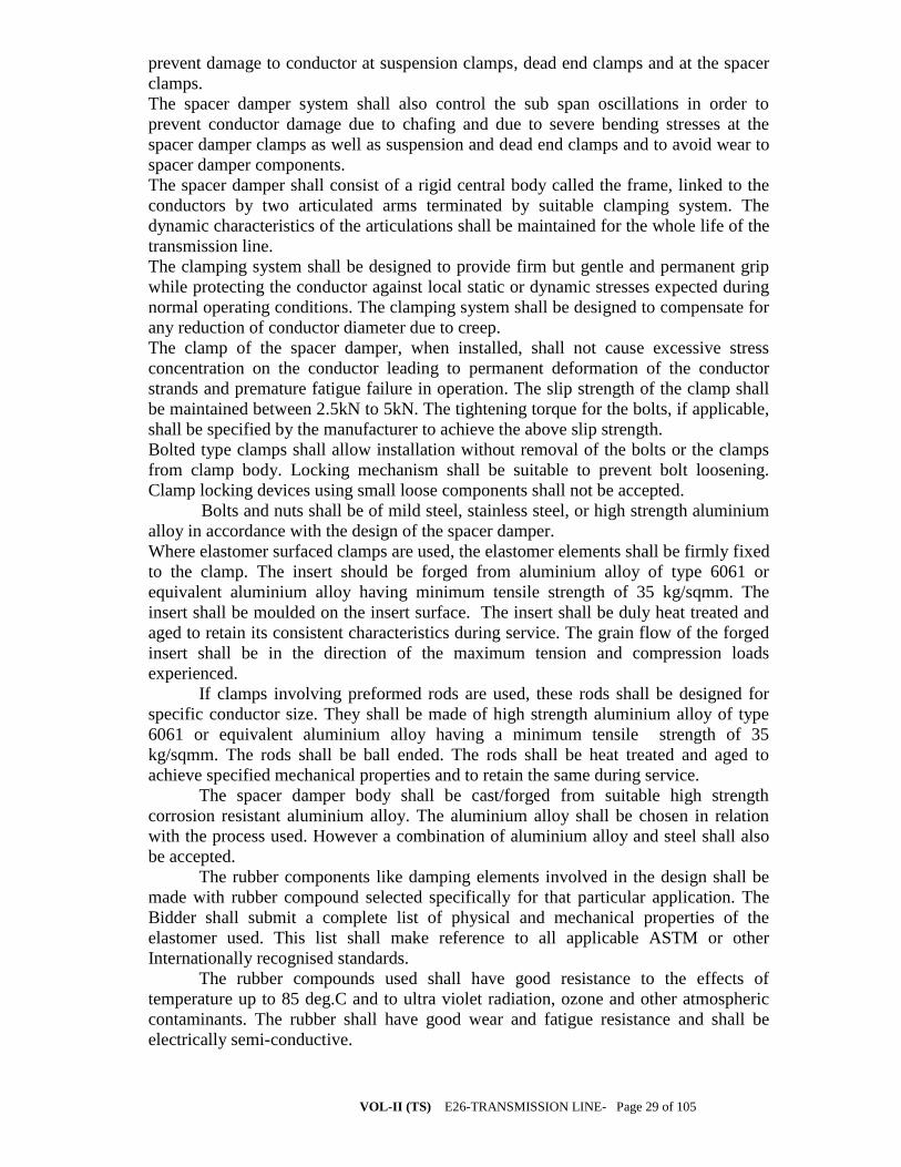
VOL-II (TS) E26-TRANSMISSION LINE- Page 29 of 105
prevent damage to conductor at suspension clamps, dead end clamps and at the spacer
clamps.
The spacer damper system shall also control the sub span oscillations in order to
prevent conductor damage due to chafing and due to severe bending stresses at the
spacer damper clamps as well as suspension and dead end clamps and to avoid wear to
spacer damper components.
The spacer damper shall consist of a rigid central body called the frame, linked to the
conductors by two articulated arms terminated by suitable clamping system. The
dynamic characteristics of the articulations shall be maintained for the whole life of the
transmission line.
The clamping system shall be designed to provide firm but gentle and permanent grip
while protecting the conductor against local static or dynamic stresses expected during
normal operating conditions. The clamping system shall be designed to compensate for
any reduction of conductor diameter due to creep.
The clamp of the spacer damper, when installed, shall not cause excessive stress
concentration on the conductor leading to permanent deformation of the conductor
strands and premature fatigue failure in operation. The slip strength of the clamp shall
be maintained between 2.5kN to 5kN. The tightening torque for the bolts, if applicable,
shall be specified by the manufacturer to achieve the above slip strength.
Bolted type clamps shall allow installation without removal of the bolts or the clamps
from clamp body. Locking mechanism shall be suitable to prevent bolt loosening.
Clamp locking devices using small loose components shall not be accepted.
Bolts and nuts shall be of mild steel, stainless steel, or high strength aluminium
alloy in accordance with the design of the spacer damper.
Where elastomer surfaced clamps are used, the elastomer elements shall be firmly fixed
to the clamp. The insert should be forged from aluminium alloy of type 6061 or
equivalent aluminium alloy having minimum tensile strength of 35 kg/sqmm. The
insert shall be moulded on the insert surface. The insert shall be duly heat treated and
aged to retain its consistent characteristics during service. The grain flow of the forged
insert shall be in the direction of the maximum tension and compression loads
experienced.
If clamps involving preformed rods are used, these rods shall be designed for
specific conductor size. They shall be made of high strength aluminium alloy of type
6061 or equivalent aluminium alloy having a minimum tensile strength of 35
kg/sqmm. The rods shall be ball ended. The rods shall be heat treated and aged to
achieve specified mechanical properties and to retain the same during service.
The spacer damper body shall be cast/forged from suitable high strength
corrosion resistant aluminium alloy. The aluminium alloy shall be chosen in relation
with the process used. However a combination of aluminium alloy and steel shall also
be accepted.
The rubber components like damping elements involved in the design shall be
made with rubber compound selected specifically for that particular application. The
Bidder shall submit a complete list of physical and mechanical properties of the
elastomer used. This list shall make reference to all applicable ASTM or other
Internationally recognised standards.
The rubber compounds used shall have good resistance to the effects of
temperature up to 85 deg.C and to ultra violet radiation, ozone and other atmospheric
contaminants. The rubber shall have good wear and fatigue resistance and shall be
electrically semi-conductive.
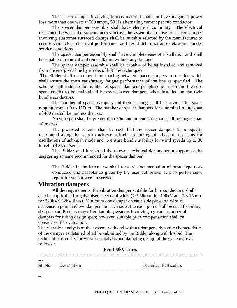
VOL-II (TS) E26-TRANSMISSION LINE- Page 30 of 105
The spacer damper involving ferrous material shall not have magnetic power
loss more than one watt at 600 amps., 50 Hz alternating current per sub conductor.
The spacer damper assembly shall have electrical continuity. The electrical
resistance between the subconductors across the assembly in case of spacer damper
involving elastomer surfaced clamps shall be suitably selected by the manufacturer to
ensure satisfactory electrical performance and avoid deterioration of elastomer under
service conditions.
The spacer damper assembly shall have complete ease of installation and shall
be capable of removal and reinstallation without any damage.
The spacer damper assembly shall be capable of being installed and removed
from the energised line by means of hot line techniques.
The Bidder shall recommend the spacing between spacer dampers on the line which
shall ensure the most satisfactory fatigue performance of the line as specified. The
scheme shall indicate the number of spacer dampers per phase per span and the sub-
span lengths to be maintained between spacer dampers when installed on the twin
bundle conductors.
The number of spacer dampers and their spacing shall be provided for spans
ranging from 100 to 1100m. The number of spacer dampers for a nominal ruling span
of 400 m shall be not less than six.
No sub-span shall be greater than 70m and no end sub-span shall be longer than
40 metres.
The proposed scheme shall be such that the spacer dampers be unequally
distributed along the span to achieve sufficient detuning of adjacent sub-spans for
oscillations of sub-span mode and to ensure bundle stability for wind speeds up to 30
kms/hr (8.33 m./sec.).
The Bidder shall furnish all the relevant technical documents in support of the
staggering scheme recommended for the spacer damper.
The Bidder in the latter case shall forward documentation of proto type tests
conducted and acceptance given by the user authorities as also performance
report for such towers in service.
Vibration dampers All the requirements for vibration damper suitable for line conductors, shall
also be applicable for galvanised steel earthwires (7/3.66mm. for 400kV and 7/3.15mm.
for 220kV/132kV lines). Minimum one damper on each side per earth wire at
suspension point and two dampers on each side at tension point shall be used for ruling
design span. Bidders may offer damping systems involving a greater number of
dampers for ruling design span; however, suitable price compensation shall be
considered for evaluation.
The vibration analysis of the system, with and without dampers, dynamic characteristic
of the damper as detailed shall be submitted by the Bidder along with his bid. The
technical particulars for vibration analysis and damping design of the system are as
follows :
For 400kV Lines
---------------------------------------------------------------------------------------------------------
---
Sl. No. Description Technical Particulars
---------------------------------------------------------------------------------------------------------
--

VOL-II (TS) E26-TRANSMISSION LINE- Page 31 of 105
1. Configuration Two galvanised steel earthwires in horizontal configuration 2. Span length in meters Ruling design span 400 meters Maximum span 1100 meters Minimum span 1 00 meters 3. Tensile load in each Wind Zone : 5
earthwire for ruling span (50m/s)
a) At temperature of 5o C and still air 1368 Kgf b) At temperature of 5o C and 36% full wind 2056 Kgf c) At temperature of 32o C and full wind 3593 Kgf 4. Maximum permissible dynamic strain +/- 150 micro strains
For 132kV and 220kV Lines
---------------------------------------------------------------------------------------------------------
---
Sl. No. Description Technical Particulars
---------------------------------------------------------------------------------------------------------
---
1 . Configuration One galvanised steel earthwire in horizontal configuration . 2. Span length in meters 220 kV Line 132 kV Line Ruling design span 350 meters 300 meters Maximum span 1100 meters 1000 meters Minimum span 100 meters 100 meters 3. Tensile load in Wind Zone:5 Wind Zone:5 each earthwire (50m/s) (50m/s) for ruling span a) At temperature 1120 Kgf. 1120 Kgf. of 5 deg.C and still air b) At temperature 1667 Kgf. 1606 Kgf. of 5 deg.C and
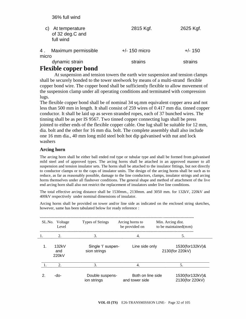
VOL-II (TS) E26-TRANSMISSION LINE- Page 32 of 105
36% full wind c) At temperature 2815 Kgf. 2625 Kgf. of 32 deg.C and full wind 4 . Maximum permissible +/- 150 micro +/- 150 micro dynamic strain strains strains
Flexible copper bond At suspension and tension towers the earth wire suspension and tension clamps
shall be securely bonded to the tower steelwork by means of a multi-strand flexible
copper bond wire. The copper bond shall be sufficiently flexible to allow movement of
the suspension clamp under all operating conditions and terminated with compression
lugs.
The flexible copper bond shall be of nominal 34 sq.mm equivalent copper area and not
less than 500 mm in length. It shall consist of 259 wires of 0.417 mm dia. tinned copper
conductor. It shall be laid up as seven stranded ropes, each of 37 bunched wires. The
tinning shall be as per IS 9567. Two tinned copper connecting lugs shall be press
jointed to either ends of the flexible copper cable. One lug shall be suitable for 12 mm,
dia. bolt and the other for 16 mm dia. bolt. The complete assembly shall also include
one 16 mm dia., 40 mm long mild steel bolt hot dip galvanised with nut and lock
washers
Arcing horn
The arcing horn shall be either ball ended rod type or tubular type and shall be formed from galvanised
mild steel and of approved types. The arcing horns shall be attached in an approved manner to all
suspension and tension insulator sets. The horns shall be attached to the insulator fittings, but not directly
to conductor clamps or to the caps of insulator units. The design of the arcing horns shall be such as to
reduce, as far as reasonably possible, damage to the line conductors, clamps, insulator strings and arcing
horns themselves under all flashover conditions. The general shape and method of attachment of the live
end arcing horn shall also not restrict the replacement of insulators under live line conditions.
The total effective arcing distance shall be 1530mm., 2130mm. and 3050 mm. for 132kV, 220kV and
400kV respectively under nominal dimensions of insulator.
Arcing horns shall be provided on tower and/or line side as indicated on the enclosed string sketches,
however, same has been tabulated below for ready reference :
-------------------------------------------------------------------------------------------- -----------------------
SL.No. Voltage Types of Strings Arcing horns to Min. Arcing dist.
Level be provided on to be maintained(mm)
-------------------------------------------------------------------------------------------------------------------
1. 2. 3. 4. 5.
1. 132kV Single ‘I’ suspen- Line side only 1530(for132kV)& and sion strings 2130(for 220kV) 220kV
1. 2. 3. 4. 5.
2. -do- Double suspens- Both on line side 1530(for132kV)& ion strings and tower side 2130(for 220kV)
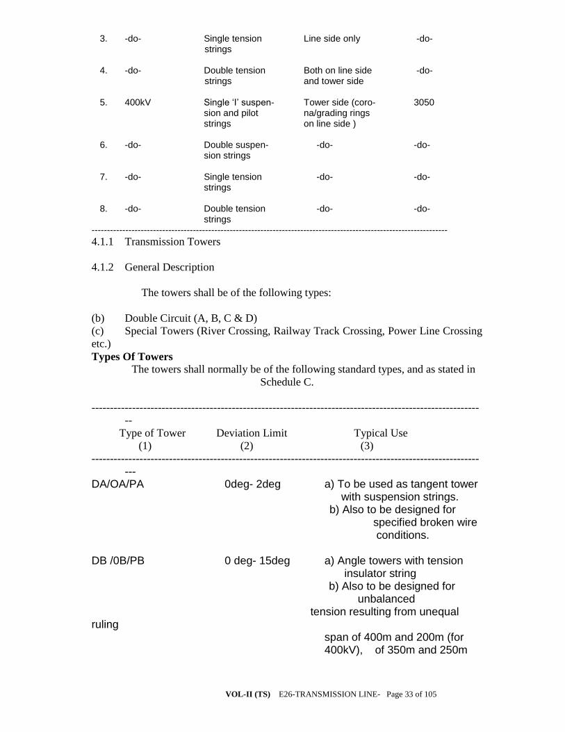
VOL-II (TS) E26-TRANSMISSION LINE- Page 33 of 105
3. -do- Single tension Line side only -do- strings 4. -do- Double tension Both on line side -do- strings and tower side 5. 400kV Single ‘I’ suspen- Tower side (coro- 3050 sion and pilot na/grading rings strings on line side ) 6. -do- Double suspen- -do- -do- sion strings 7. -do- Single tension -do- -do- strings 8. -do- Double tension -do- -do- strings --------------------------------------------------------------------------------------------------------------------
4.1.1 Transmission Towers
4.1.2 General Description
The towers shall be of the following types:
(b) Double Circuit (A, B, C & D)
(c) Special Towers (River Crossing, Railway Track Crossing, Power Line Crossing
etc.)
Types Of Towers
The towers shall normally be of the following standard types, and as stated in
Schedule C.
---------------------------------------------------------------------------------------------------------
--
Type of Tower Deviation Limit Typical Use
(1) (2) (3)
---------------------------------------------------------------------------------------------------------
---
DA/OA/PA 0deg- 2deg a) To be used as tangent tower with suspension strings. b) Also to be designed for specified broken wire conditions. DB /0B/PB 0 deg- 15deg a) Angle towers with tension insulator string b) Also to be designed for unbalanced tension resulting from unequal ruling span of 400m and 200m (for 400kV), of 350m and 250m
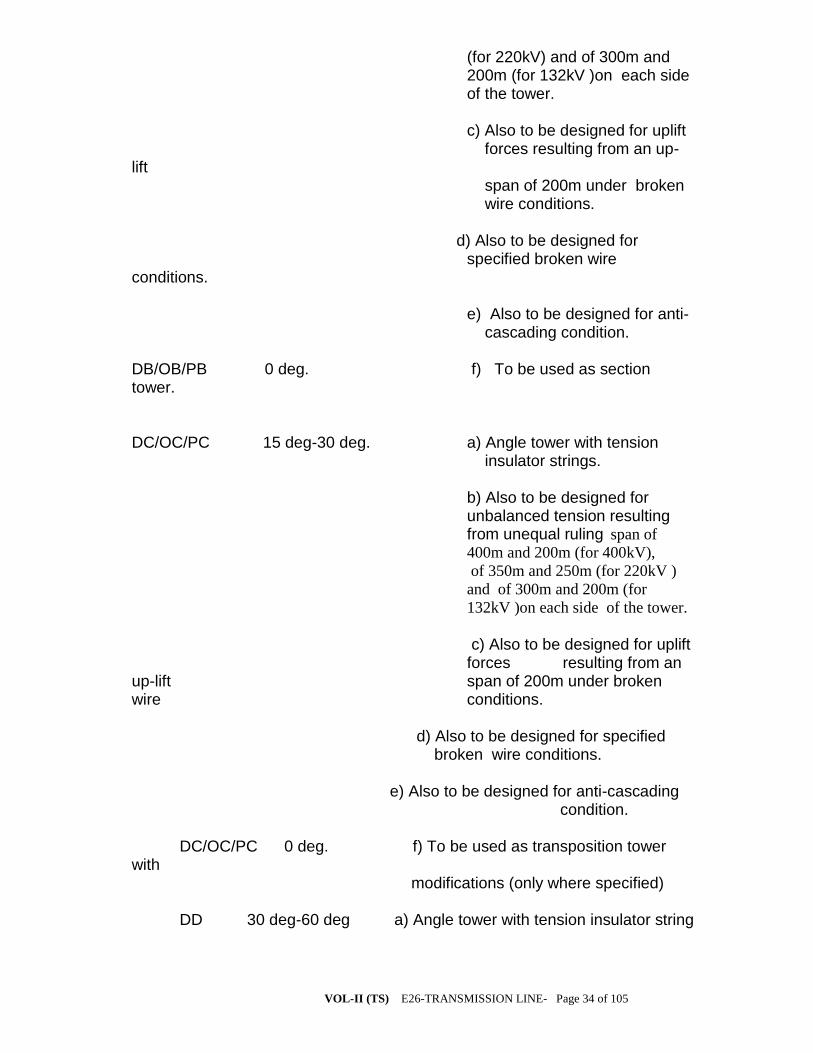
VOL-II (TS) E26-TRANSMISSION LINE- Page 34 of 105
(for 220kV) and of 300m and 200m (for 132kV )on each side of the tower. c) Also to be designed for uplift forces resulting from an up-lift span of 200m under broken wire conditions. d) Also to be designed for specified broken wire conditions. e) Also to be designed for anti- cascading condition. DB/OB/PB 0 deg. f) To be used as section tower. DC/OC/PC 15 deg-30 deg. a) Angle tower with tension insulator strings. b) Also to be designed for unbalanced tension resulting from unequal ruling span of
400m and 200m (for 400kV),
of 350m and 250m (for 220kV )
and of 300m and 200m (for
132kV )on each side of the tower.
c) Also to be designed for uplift forces resulting from an up-lift span of 200m under broken wire conditions. d) Also to be designed for specified broken wire conditions. e) Also to be designed for anti-cascading condition. DC/OC/PC 0 deg. f) To be used as transposition tower with modifications (only where specified) DD 30 deg-60 deg a) Angle tower with tension insulator string

VOL-II (TS) E26-TRANSMISSION LINE- Page 35 of 105
b) Also to be designed for the unbalanced tension resulting from unequal ruling span of 400m and 200m (for 400kV), of 350m and 250m (for 220kV) and of 300m and 200m (for 132kV) on each side of the tower. c) Also to be designed for uplift forces resulting from an uplift span of 300m(for 400kV) and 200m (for 132kV and20kV) under broken wire conditions. d) Also to be designed for specified broken wire conditions. e) Dead end with 0 deg to 15 deg deviation on line and 0 deg to 30 deg for sub-station side (slack span side). DD 0 deg f) Complete dead end.
g) For river crossing anchoring with
longer wind span with 0 deg deviation
on crossing span side and 0 deg to 30
deg deviation on other sides .
Note: The above towers can also be used for longer span with smaller angle of deviations. (To be decided as per the tower spotting data to be submitted by the Contractor and approved by Project Manager.)
4.1.3 The towers shall be of the self-supporting type, built up of lattice steel sections
or members and designed to carry the power conductors with necessary insulators.
Ground wires and all fittings under all loading conditions. Outline diagrams of the
towers required are to be furnished by the Bidder.
4.1.4 The towers shall be fully galvanized structures built up of structural mild steel
sections. All members shall be connected with bolts, nuts and spring washers.
For design of structure weight span limits given in Table 5.1 shall prevail.
TABLE 5.1 (a)
For 132 kV Line
Tower Normal Condition Broken Wire Cond Type Max. Min. Max. Min. (m) (m) (m) (m)
DA 450 150 270 100

VOL-II (TS) E26-TRANSMISSION LINE- Page 36 of 105
DB, DC & DD 450 0 270 -200
TABLE 5.1 (b)
For 220 kV Line
Tower Normal Condition Broken Wire Cond Type Max. Min. Max. Min. (m) (m) (m) (m)
DA 525 200 315 100
DB, DC & DD 525 0 315 -200
TABLE 5.1 (c)
For 400 kV Line
Tower Normal Condition Broken Wire Con Type Max. Min. Max. Min. (m) (m) (m) (m)
DA 600 200 360 100 DB, DC 600 0 360 -200 DD 600 0 360 -300
However, for calculating the tower height, an allowance of 150mm shall be provided,
over and above the specified ground clearances, at still air and maximum conductor
temperature, to account for any stringing error.
TABLE
Minimum clearance
Situation (metres)
System voltage (kV): 132 220 400 Normal ground (open country) 6.10 7.015 8.84 * Road crossings, road level 7.00 7.90 9.7 Rail crossings, rail level: 17.9 17.9 19.3 River crossings, bank level River crossings, navigable rivers, above highest as specified by the Authority flood level;(data to be obtained from Navigation Authority) Above trees 4.0 4.6 5.5 Buildings, poles, structures and walls, etc. upon which a man may stand : horizontal clearance 4.6 5.5 7.3 Same above : vertical clearance 2.9 3.8 5.6 Power lines 3.1 4.6 6.1
*Any road which is normally maintained by Government and/or other recognised public authority.
VOL-II (TS) E26-TRANSMISSION LINE- Page 37 of 105
4.1.5 Stubs and Superstructures:
(i) The stub shall mean a set of four stub angles fully galvanized from the
and shall include cleats, gussets, bolts and nuts, etc. the black portion of
the stub being cast in foundation footings. Stub length shall correspond
to foundation depth of 3-0 metres from ground level.
(ii) Superstructure shall mean the galvanized tower assembly above the stubs which
includes structural members like angle sections, cross arms, ground wire peaks,
accessories and fittings such as gusset plates, pack washers, spring, washers, ladders,
step bolts, anti climbing devices and such other items which are required for
completing the towers in all respect. Steel and zinc required for manufacturing these
items will be arranged by the supplier.
(iii) Supply of bolts and nuts and spring washers, hangers/D-shackles for attaching
suspension strings and ‘U’ bolts for attaching ground wire suspension assemblies are
included in the supply of tower.
(iv) The following provisions shall apply in connection with the procurement of
steel and zinc by the supplier.
(a) The steel used for fabrication of tower parts extensions, templates etc. shall be
of mild steel of tested quality as per IS:2062 GRA.
(b) The Bidder shall take into account the fabrication wastage while quoting the
rates. The employer will not accept any liability in connection with the wastage of steel
during fabrication or otherwise.
(c) The Bidder shall indicate in his offer the sizes of steel sections which are
proposed to be used by him in the design of towers.
(d) Substitutions, if any, of steel sections of the tower parts by higher sizes, due to
non-availability or otherwise shall be to the supplier’s account. The employer will not
accept any liability on this account.
(e) The steel shall be procured exclusively from the main steel producers. However,
sections not rolled by main producers, can be procured from re-rollers provided.
Re-rolling of structural steel sections is done from billets/ingots of tested quality.
Re-rolled sections are duly tested as per relevant standard.
(f) The zinc used for galvanizing fabricated material shall be of High Grade
Electrolytic zinc.
4.1.6 Extensions:
a) The towers shall be designed so as to be suitable for adding 3 metres, 6 metres,
9 metres extensions for maintaining adequate ground clearances without reducing the
specified factor of safety in any manner.

VOL-II (TS) E26-TRANSMISSION LINE- Page 38 of 105
b) The Buidder shall have to design leg extensions for all types of towers ranging
from minus 3 metres to plus 9 metres at intervals of 1.5 metres and such leg extensions
shall be suitable for being fitted to a normal tower as well as a tower with extensions.
This is to enable tower spotting in hilly terrain.
4.1.7 Stub setting Templates:
Stub templates shall be designed and supplied by the supplier as per
requirement for all types of towers with or without extensions. Stub
templates for standard towers and towers with extension shall be fined type.
The stub templates shall be painted with anti-corrosive paints.
4.1.8 Fasteners: Bolts, Nuts & Washers
4.1.9 All bolts shall be of property class 5.6 and nuts of property class 5.0 IS: 1367
(Part – 3) 1991 and IS: 6639-1972 shall conform to IS: 12427, they shall be galvanized
and shall have hexagonal heads and nuts, the heads being forged out of solid steel rods
and shall be truly concentric and square with the shank. The shank shall be perfectly
straight.
4.1.10 ully threaded bolts shall not be used, the length of bolts should be such that the
threaded portion shall not extend into the place of contact of the members.
4.1.11 ll bolts shall be threaded to take the full depth of the nut and threaded far
enough to permit firm gripping of the members, but not any further. It shall be ensured
that the threaded portion of each bolt protrudes not less than 3 mm and not more than 8
mm when fully tightened. All nuts shall fit hand tight to the point where the shank of
the bolt connects to the head.
4.1.12 lat and tapered washers shall be provided wherever necessary. Spring washers
shall be provided for insertion under all nuts. These washers shall be of electro-
galvanized steel and of the positive lock type. Their thickness shall be 2.5 mm for 12
mm dia bolts, 3.5 mm for 16 mm dia bolts and 4.5 mm for 20 mm dia bolts.
4.1.13 he Bidder shall furnish bolt schedules giving thickness of members connected,
size of bolts and nuts, the length of the shank, the length of the threaded portion of
bolts, sizes of bolt holes, thickness of washers and any other special details of this
nature.
4.1.14 To obviate bending stress in bolts or to reduce it to a minimum, no bolt shall
connect aggregate thickness of more than three (3) times its dia.
4.1.15 he bolt positions in assembled towers shall be as per IS: 5613 (Part-I/Section-I)
(Part-II/Section-2)-1985.
4.1.16 olts at the joints shall be so staggered that nuts may be tightened with spanners
without fouling.

VOL-II (TS) E26-TRANSMISSION LINE- Page 39 of 105
5.0 Tower Accessories
5.1 Step Bolt Ladders: These bolts shall be of property class 4.6 conform to IS:
6639-1972.
5.1.1 Each tower shall be provided with step bolts on one of the main legs, of not less
than 16 mm diameter and 175 mm long, spaced not more than 400 mm apart and
extending from about 2.5 metres above the ground level to the top of the tower. Each
step bolt shall be provided with two nuts on one end to fasten the bolt security to the
tower and button head at the other end to prevent the feet from slipping away. The step
bolts shall be capable of withstanding a vertical load not less than 1.5 KN and shall be
used as a ladder for climbing.
5.1.2 Anti-climbing devices: This shall conform to IS: 5613 (Part-I/Sec –I),
19085.
Fully galvanized barbed wire type anti-climbing device shall be provided at
a height of approximately 3 metres as an anti-climbing measure. Four layers
of barbed wires will be provided each inside and outside the tower in
horizontal plane, spacing between the layers being 140 to 150 mm. The
towers to be designed by the supplier shall have provision to fixed the
barbed wire as indicated above. Thus the angle pieces with notches for
accommodating barbed wire shall be designed and supplied with the towers
along with provision for suitable bolt holes on leg members for fitting bolt
holes on leg member for fitting the angles. The scheme of the anti-climbing
device shall be submitted along with the tower drawing. Barbed wire shall
be included in the scope of bidder.
5.1.3 Insulator strings and ground wire clamp attachments
(a) For the attachment of suspension insulator strings a suitable swinging hanger on
the tower shall be provided so as to obtain requisite clearance under extreme swinging
conditions and free swinging of the string.
The hanger shall be designed to withstand an ultimate tensile
strength of 11.500 kg.
5.1.4 (a)For ground wires at suspension towers suitable ‘U’ Bolts strong enough to
withstand the full designed loads shall be provided to accommodate the hook of the
ground wire suspension clamps.
(b) At tension towers, horizontal strain plates of suitable dimensions on the
underside of each power cross-arm tip and at the top ground wire peak shall be
provided for taking the ‘D’ Shackles of the tension insulator strings or ground wire
tension clamps, as the case may be. Full details of the attachments shall be submitted by
the supplier for the employer’s approval before commencing with mass fabrication.
5.1.5 Phase Plate
VOL-II (TS) E26-TRANSMISSION LINE- Page 40 of 105
Phase plate shall be of mild steel of 16 gauge vitreous enameled at back and
front, circular in shape and diameter 75 mm. One set of phase plate shall be
consisting of 3 plates red, yellow and blue coloured accordingly to indicate
the phase of the conductor. There shall be one fixing bolt on the plate. This
shall conform to IS: 5613 (Part-II/Section01) of latest edition.
5.1.6 Number Plate
The number plate shall be mild steel vitreous enameled at back and front,
200 mmx 150 mm, rectangular shape and inscribed thereon shall be the
number of the tower location preceded by letter corresponding to the short
name of the line and the type of towers. There shall be two fixing bolts on
both end of the plates. The dimension and details of the number plate shall
be as per IS: 5613 (Part-II/Section1 & Section-2), 1985.
5.1.7 Danger Plate
These shall be of mild steel vitreous enameled at back and front 250 x 200
mm rectangular shape and inscribed thereon shall be in signal red the work
‘DANGER’ with its Oriya and Hindi translation and also with the
inscription of Bone and Scull and voltage of the line. There shall be two
holes on the plates for fixing. This shall conform to IS: 2551 (latest edition).
5.1.8 Details to Tower Fabrication Workmanship
5.1.9 Except where hereinafter modified details of fabrications shall confirm to IS:
802 (Part-II)-1978.
5.1.10 But splices shall generally be used such that the inside cleat angle and outside
plates are designed to transmit load. The inside cleat angle shall not be less than half the
thickness of the connected heaviest member plus 2 mm. Lap splices may also be used
for connecting members of unequal size in such a manner that the inside angle of the
lap splice shall be rounded at the heel to fit the fillet of the outside angle. All splices
shall develop full stress in the members connected through bolts. But as well as lap
splices shall be made as above and as close to and above the main panel point as far as
possible.
5.1.11 Points shall be so designed so as to avoid eccentricity. The use of gusset plates
for joining tower members shall be avoided as far as possible. However, where
connections are such that the elimination of the gusset plates would result in eccentric
joints then gussets plates and spacer plates may be used in conformity with modern
practices. The thickness of the gusset plate, required to transmit stress, shall not be less
than that of the thinnest of connected member but not less than 5 mm in any case.
The use of filler in connection shall be avoided as far as possible. The
diagonal web members in tension may be connected entirely to the gusset
plate where necessary so as to avoid the use of filler and it shall be
connected at the point of inter-section by one or more bolts.

VOL-II (TS) E26-TRANSMISSION LINE- Page 41 of 105
5.1.12 The tower structures shall be accurately fabricated to bolt together easily at
site without any strain on the bolts.
5.1.13 No angle member shall have the two leg flanges brought together by closing
the angle.
5.1.14 The diameter of the hole shall be equal to the diameter of bolt plus 1.5 mm.
5.1.15 The structure shall be designed such that all parts are accessible for
inspection and cleaning. Drain holes shall be provided at all points where pockets of
depressions are likely to hold water.
5.1.16 All similar parts shall be made strictly interchangeable. All steel sections before
any work is done on them, shall be carefully leveled, straightened and made true to
detailed drawings by methods which shall not injure the materials so that when
assembled, the different matching surfaces are in close contact throughout. No rough
edges shall be permitted any where in the structure.
5.1.17 Drilling and Punching
(a) Before any cutting work is started, all steel sections shall be carefully
straightened and trued by pressure and not by hammering. They shall again be trued
after being punched and drilled.
(b) Holes for bolts shall be drilled of punched with a jig but drilled holes are
preferred. The following maximum tolerance of accuracy of punched holes is
permissible.
(i) Holes must be perfectly circular and no tolerance in this respect
is permissible.
(ii) The maximum allowable difference in diameter of the
holes on the two sides of plates or angle is 0.8 mm i.e. the
allowable taper in punched holes should not exceed 0.8 mm on
diameter.
(iii) Holes must be square with the plates or angles and have their
walls parallel.
© All burrs left by drills or punches shall be removed completely. When
the tower members be truly opposite to each other. Drilling or reaming
to enlarge defective holes is not permitted.
5.1.18 Erection Mark:
Each individual member shall have an erection mark conforming to the
component number given to it in the fabrication drawings. This mark shall
be done with marking dies of 16 mm size before galvanizing and shall be
legible after galvanising.

VOL-II (TS) E26-TRANSMISSION LINE- Page 42 of 105
The erection mark shall be A-BB-CC-DDD where
A Employer code assigned to the supplier (Alphabet).
BB Supplier’s Mark (Numerical)
CC Tower type (Alphabet)
DDD Number mark to be assigned by Supplier (numerical).
5.1.19.1 Galvanizing
The super structure of all towers and stubs upto 150 mm below plinth level
(Top of concrete pedestal) shall be galvanized. Galvanizing of tower
members and stub shall be in conformity with IS: 4759-1984 and shall be
done after all fabrication work has been completed except that the nuts may
be tapped or return after galvanizing. Threads of bolts and nuts after
galvanizing shall have a neat fit and shall be such that they can be turned
with fingers throughout the length of the threads of bolts and they shall be
capable of developing the full strength of the bolts. Spring washers shall be
electro-galvanized as per Grade – 4 of IS: 1573 – 1986. Galvanizing for
fasteners shall conform to IS: 1367 (Part-XIII) – 1978.
5.1.19.2 Quantities and Weights
5.1.20 The quantities stated in Annexure – I are only provisional. Final quantities will
be informed by the employer to the supplier on completion of detailed survey.
However, bids will be evaluated based on quantities indicated in the Annexure – I.
5.1.21 The employer reserves the right to order for the final quantities at the rates
quoted in the bid, which shall be valid throughout the pendency of the contract.
5.1.21.1 The unit weight of each type of tower stubs, super structure and
extension be furnished by the Bidder. The weight of tower shall mean the weight of
tower calculated by using the black section(ungalvanized) weight of steel members
including stubs, of the sizes indicated in the approved fabrication drawings and bills of
materials, without taking into consideration the reduction in weights due to holes,
notches, cuts, etc. but taking into consideration the weight of special fittings.
5.1.21.2 Tower designs Superstructure
5.1.21.3 Wind Pressure
The wind pressure on towers, power conductors and earth wire shall be as
per IS: 802 (Part-I/Sec-I) – 1995.
280

VOL-II (TS) E26-TRANSMISSION LINE- Page 43 of 105
5.1.21.4 Design Temperatures
The following temperature range for the power conductor and ground wires
shall be adopted for the line design confirming to IS: 802 (Part –I/Sec – I) –
1995.
i) Minimum temperature 50˚C.
ii) Every day temperature 32˚C
iii) Maximum temperature of:
a) Conductor 75˚C for ACSR Moose/Zebra/Panther
90˚C for AAAC (Moose equivalent)
b) Ground wire 53˚C
exposed to Sun.
5.1.21.5 Factors of Safety & Span details
a) Factory of safety.
The factor of safety based on crippling strength of struts and elastic limit
of tension members shall not be less than 2(two) under normal condition
and 1.5 (one and a half) under broken wire conditions for all the
members of the towers and their cross arms.
b) Normal Span
The normal span of the line shall be 300 metres for 400 KV and 220 kV
and 250 meters for 132 kV.
c) Wind and weight spans
The wind and weight spans to be adopted in the design of the structures
shall be as follows:
i) Wind Span
The wind span is the sum of the two half spans adjacent to the
support under consideration. In case of towers located on an
perfectly horizontal terrain, this shall be the normal span. For
design purposes the wind on conductor shall be calculated on at
least 1.1 times the normal.
ii) Weight Span
The weight span is the horizontal distance between the lowest
point of the conductors on the two spans adjacent to the tower.

VOL-II (TS) E26-TRANSMISSION LINE- Page 44 of 105
All C and D type towers shall be designed for uplift spans
(minimum) weight spans in the following table also. These are
applicable both for pointed and square cross arms.
For details of cross arms and towers, the span limits given below
shall prevail.
WEIGHT SPANS
Tower
Type
400/220 KV 132KV
Normal
Condition
Broken wire
condition
Normal
Condition
Broken wire
condition
Max. Min. Max. Min. Max. Min. Max. Min.
A & B 525 100 300 100 320 100 250 100
C & D 600 100 300 100 320 100 250 100
5.1.21.6 Conductor and Ground wire Configuration
For single circuit towers the three phases shall be Delta formation. One
number of ACSR conductor shall be used for each phase. One galvanized
steel wire shall be used as ground wire. The ground wire shall be continuous
and shall be provided above the conductors at suitable elevation to offer
effective shielding and safe clearances. For double circuit towers the phases
shall be in vertical formation with phase to phase horizontal spacing of not
less than 8.4 meters and vertical 4.9 meters for 220 kV.
5.1.21.7Loads on Towers
i) Transverse Loads:
Transverse load due to wind on towers conductors and under broken wire earthwire
shall be calculated in accordance with IS: 802(Part-I/Sec-I)-1995.
ii) Longitudinal Loads due to wind on towers conductors and shield shall be
calculated as per IS: 802 (Part-I/Sec-I)-1995.
iii) Vertical Loads:
The vertical load due to conductors and ground wire shall also include 150 kg.
As weight of a Lineman with tools. These loads are in addition to the vertical loads due
to insulator fittings and the dead weight of the structure. The weight of a Lineman with
tool should not be considered in minimum vertical load calculation. An additional
erection load of 3.5 KN shall also be considered for the design of the tower. The
stringing procedure shall ensure that the above vertical loads are not exceeded. For
calculating vertical loads the following insulator weights may be considered.
400/220/132 KV
VOL-II (TS) E26-TRANSMISSION LINE- Page 45 of 105
Each single suspension insulator string 160 kg
Each double suspension insulator string 320 kg
Each double tension insulator string 420 kg
Pilot string for 60˚ tower 160 kg
iv) Broken Wire condition
a) Suspension Tower Type A/DA
Breaking of any one power conductor in one phase only, resulting in instanceous
unbalance tension of 50% of conductor tension at 32˚C without wind or breaking of
one earthwire resulting in an unbalance tension equal to the maximum tension of the
ground wire whichever is more stringent is to be considered for design along with
appropriate impact factor.
b) Tower Type B & C
Breakage of two phases on the same side and on the same span or breakage of any one
phase and any one ground wire on the same span whichever combination is more
stringent along with appropriate impact factor for a particular member.
c) Tower Type D/DD
Breakage of all the three phases on the same side and on the same span or breakage of
two phases and any one ground wire on the same span, whichever combination is more
stringent along with appropriate impact factor for a particular member. Cross arms for
angle tower shall be of equal length for both sides.
v) Design Load
Employer’s requirement for design longitudinal and transverse loads shall confirm to
IS: 802(Part-I/Sec-I)-1995.
The Bidder shall furnish the details of design loads proposed to be adopted in the tower
design in accordance with this specification.
The design criteria and other special requirements as stipulated for special towers shall
be applicable for river crossing/special towers.
5.1.21.8Tower Steel Sections:
i) Steel sections of tested quality in conformity with IS: 2062 GRA are to be used
in towers, extensions and stub setting templates. No individual members shall be
longer than 6000 mm.
For designing of towers only rationalized steel sections shall be used. During execution
of the project, if any particular section is not available, the same shall be substituted by
higher section at no extra cost. However, design approval for such substitution shall be
obtained from the employer.
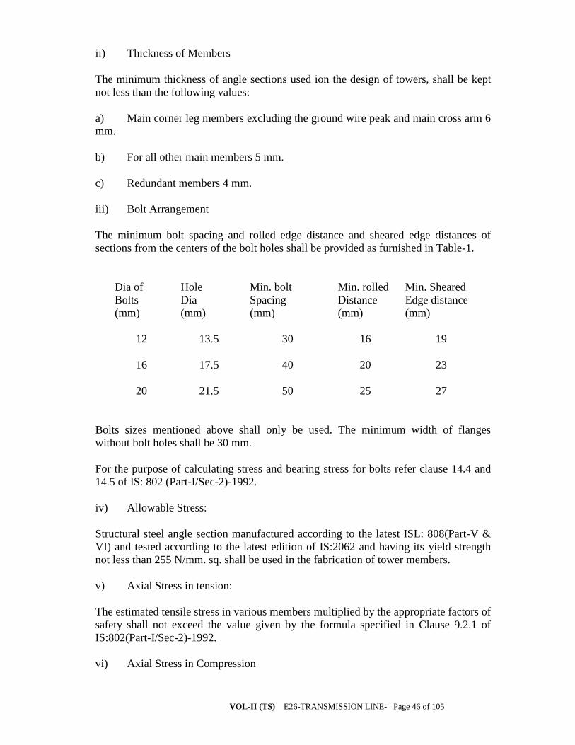
VOL-II (TS) E26-TRANSMISSION LINE- Page 46 of 105
ii) Thickness of Members
The minimum thickness of angle sections used ion the design of towers, shall be kept
not less than the following values:
a) Main corner leg members excluding the ground wire peak and main cross arm 6
mm.
b) For all other main members 5 mm.
c) Redundant members 4 mm.
iii) Bolt Arrangement
The minimum bolt spacing and rolled edge distance and sheared edge distances of
sections from the centers of the bolt holes shall be provided as furnished in Table-1.
Dia of
Bolts
(mm)
Hole
Dia
(mm)
Min. bolt
Spacing
(mm)
Min. rolled
Distance
(mm)
Min. Sheared
Edge distance
(mm)
12 13.5 30 16 19
16 17.5 40 20 23
20 21.5 50 25 27
Bolts sizes mentioned above shall only be used. The minimum width of flanges
without bolt holes shall be 30 mm.
For the purpose of calculating stress and bearing stress for bolts refer clause 14.4 and
14.5 of IS: 802 (Part-I/Sec-2)-1992.
iv) Allowable Stress:
Structural steel angle section manufactured according to the latest ISL: 808(Part-V &
VI) and tested according to the latest edition of IS:2062 and having its yield strength
not less than 255 N/mm. sq. shall be used in the fabrication of tower members.
v) Axial Stress in tension:
The estimated tensile stress in various members multiplied by the appropriate factors of
safety shall not exceed the value given by the formula specified in Clause 9.2.1 of
IS:802(Part-I/Sec-2)-1992.
vi) Axial Stress in Compression
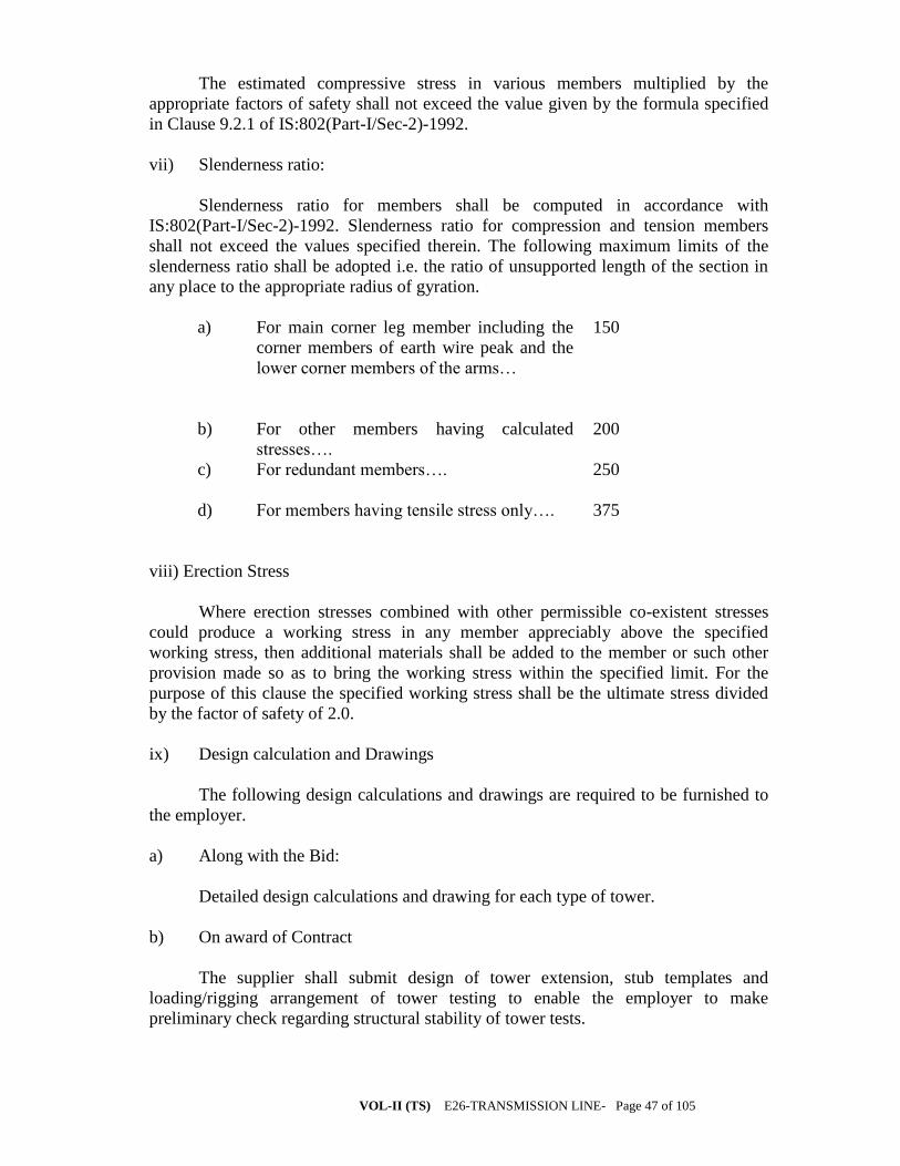
VOL-II (TS) E26-TRANSMISSION LINE- Page 47 of 105
The estimated compressive stress in various members multiplied by the
appropriate factors of safety shall not exceed the value given by the formula specified
in Clause 9.2.1 of IS:802(Part-I/Sec-2)-1992.
vii) Slenderness ratio:
Slenderness ratio for members shall be computed in accordance with
IS:802(Part-I/Sec-2)-1992. Slenderness ratio for compression and tension members
shall not exceed the values specified therein. The following maximum limits of the
slenderness ratio shall be adopted i.e. the ratio of unsupported length of the section in
any place to the appropriate radius of gyration.
a) For main corner leg member including the
corner members of earth wire peak and the
lower corner members of the arms…
150
b)
For other members having calculated
stresses….
200
c) For redundant members…. 250
d) For members having tensile stress only…. 375
viii) Erection Stress
Where erection stresses combined with other permissible co-existent stresses
could produce a working stress in any member appreciably above the specified
working stress, then additional materials shall be added to the member or such other
provision made so as to bring the working stress within the specified limit. For the
purpose of this clause the specified working stress shall be the ultimate stress divided
by the factor of safety of 2.0.
ix) Design calculation and Drawings
The following design calculations and drawings are required to be furnished to
the employer.
a) Along with the Bid:
Detailed design calculations and drawing for each type of tower.
b) On award of Contract
The supplier shall submit design of tower extension, stub templates and
loading/rigging arrangement of tower testing to enable the employer to make
preliminary check regarding structural stability of tower tests.
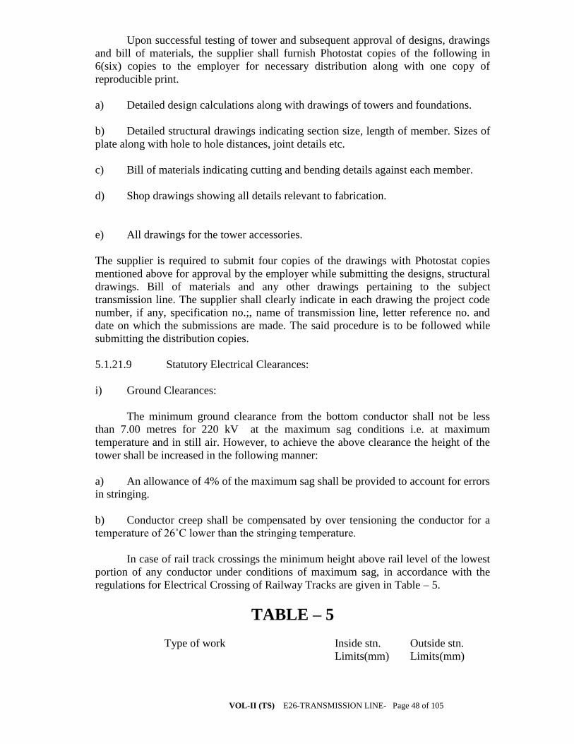
VOL-II (TS) E26-TRANSMISSION LINE- Page 48 of 105
Upon successful testing of tower and subsequent approval of designs, drawings
and bill of materials, the supplier shall furnish Photostat copies of the following in
6(six) copies to the employer for necessary distribution along with one copy of
reproducible print.
a) Detailed design calculations along with drawings of towers and foundations.
b) Detailed structural drawings indicating section size, length of member. Sizes of
plate along with hole to hole distances, joint details etc.
c) Bill of materials indicating cutting and bending details against each member.
d) Shop drawings showing all details relevant to fabrication.
e) All drawings for the tower accessories.
The supplier is required to submit four copies of the drawings with Photostat copies
mentioned above for approval by the employer while submitting the designs, structural
drawings. Bill of materials and any other drawings pertaining to the subject
transmission line. The supplier shall clearly indicate in each drawing the project code
number, if any, specification no.;, name of transmission line, letter reference no. and
date on which the submissions are made. The said procedure is to be followed while
submitting the distribution copies.
5.1.21.9 Statutory Electrical Clearances:
i) Ground Clearances:
The minimum ground clearance from the bottom conductor shall not be less
than 7.00 metres for 220 kV at the maximum sag conditions i.e. at maximum
temperature and in still air. However, to achieve the above clearance the height of the
tower shall be increased in the following manner:
a) An allowance of 4% of the maximum sag shall be provided to account for errors
in stringing.
b) Conductor creep shall be compensated by over tensioning the conductor for a
temperature of 26˚C lower than the stringing temperature.
In case of rail track crossings the minimum height above rail level of the lowest
portion of any conductor under conditions of maximum sag, in accordance with the
regulations for Electrical Crossing of Railway Tracks are given in Table – 5.
TABLE – 5
Type of work Inside stn.
Limits(mm)
Outside stn.
Limits(mm)

VOL-II (TS) E26-TRANSMISSION LINE- Page 49 of 105
a) For unelectrified track and tracks
electrified on 1500 V.DC
i) For metre/narrow gauge 10,00017,600
ii) For broad gauge 11,200 8,800
b) Tracks electrified on 25 kV AC
for metre, narrow and broad gauge
15,300 13,300
Minimum clearance between the subject power line and any other power line
crossing shall not be less than 7000 mm.
ii) Live Metal Clearance:
The minimum live metal clearance to be provided between the live parts and
steel work of superstructure shall be as given in IS:5613 (Part-2/Sec-I).
The Bidder may adopt separate cross arm design and length for ‘D’ type towers
under dead end conditions provided adequate live metal clearance is available with at
least 15˚ angle and also provided that all the other specified conditions of this
specifications are fulfilled. In case pilot insulator strings are proposed to be used, the
angle of swing to be considered shall be minimum of 15˚.
In computing live metal clearances, the dimensions of suspension and tension
string shall be taken as given in drawings attached herewith. The design of the towers
shall be such that it should satisfy all the above conditions when clearances are
measured from any live point of the insulator strings.
iii) Angle Shielding
The angle shielding, defined as the angle formed by the line joining the center
lines of the ground wire and outer conductor in still air, at tower supports, to the
vertical line through the center line of the ground wire shall not be more than 30˚. The
drop of the ground wire clamp which is employer supplied item should be considered
while calculating the minimum angle of protection. For estimating the minimum angle
of protection the drop of ground wire suspension clamp along with U-bolt may be
taken as 150 mm.
iv) Mid Span Clearance
The minimum vertical span clearance between any of the earthwire and the
nearest power conductor under all temperatures and in still air condition in the normal
ruling span shall be 8.10 metres for 220 kV. Further the tensions of the earthwires and
power conductors, shall be so co-ordinated that the sag of earthwires shall be at least
10% less than that of the power conductors under all temperatures and loading
conditions.
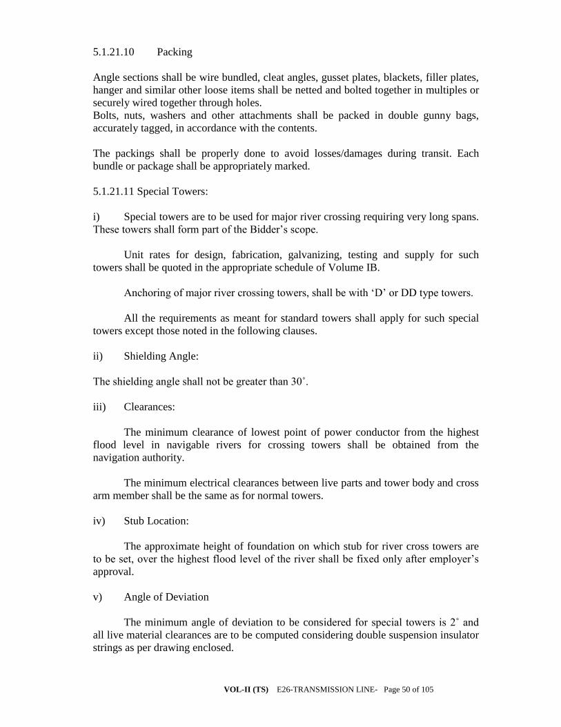
VOL-II (TS) E26-TRANSMISSION LINE- Page 50 of 105
5.1.21.10 Packing
Angle sections shall be wire bundled, cleat angles, gusset plates, blackets, filler plates,
hanger and similar other loose items shall be netted and bolted together in multiples or
securely wired together through holes.
Bolts, nuts, washers and other attachments shall be packed in double gunny bags,
accurately tagged, in accordance with the contents.
The packings shall be properly done to avoid losses/damages during transit. Each
bundle or package shall be appropriately marked.
5.1.21.11 Special Towers:
i) Special towers are to be used for major river crossing requiring very long spans.
These towers shall form part of the Bidder’s scope.
Unit rates for design, fabrication, galvanizing, testing and supply for such
towers shall be quoted in the appropriate schedule of Volume IB.
Anchoring of major river crossing towers, shall be with ‘D’ or DD type towers.
All the requirements as meant for standard towers shall apply for such special
towers except those noted in the following clauses.
ii) Shielding Angle:
The shielding angle shall not be greater than 30˚.
iii) Clearances:
The minimum clearance of lowest point of power conductor from the highest
flood level in navigable rivers for crossing towers shall be obtained from the
navigation authority.
The minimum electrical clearances between live parts and tower body and cross
arm member shall be the same as for normal towers.
iv) Stub Location:
The approximate height of foundation on which stub for river cross towers are
to be set, over the highest flood level of the river shall be fixed only after employer’s
approval.
v) Angle of Deviation
The minimum angle of deviation to be considered for special towers is 2˚ and
all live material clearances are to be computed considering double suspension insulator
strings as per drawing enclosed.
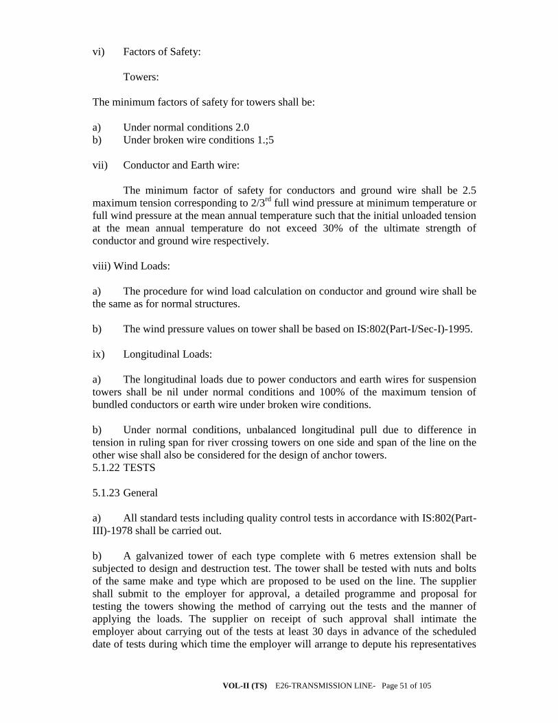
VOL-II (TS) E26-TRANSMISSION LINE- Page 51 of 105
vi) Factors of Safety:
Towers:
The minimum factors of safety for towers shall be:
a) Under normal conditions 2.0
b) Under broken wire conditions 1.;5
vii) Conductor and Earth wire:
The minimum factor of safety for conductors and ground wire shall be 2.5
maximum tension corresponding to 2/3rd
full wind pressure at minimum temperature or
full wind pressure at the mean annual temperature such that the initial unloaded tension
at the mean annual temperature do not exceed 30% of the ultimate strength of
conductor and ground wire respectively.
viii) Wind Loads:
a) The procedure for wind load calculation on conductor and ground wire shall be
the same as for normal structures.
b) The wind pressure values on tower shall be based on IS:802(Part-I/Sec-I)-1995.
ix) Longitudinal Loads:
a) The longitudinal loads due to power conductors and earth wires for suspension
towers shall be nil under normal conditions and 100% of the maximum tension of
bundled conductors or earth wire under broken wire conditions.
b) Under normal conditions, unbalanced longitudinal pull due to difference in
tension in ruling span for river crossing towers on one side and span of the line on the
other wise shall also be considered for the design of anchor towers.
5.1.22 TESTS
5.1.23 General
a) All standard tests including quality control tests in accordance with IS:802(Part-
III)-1978 shall be carried out.
b) A galvanized tower of each type complete with 6 metres extension shall be
subjected to design and destruction test. The tower shall be tested with nuts and bolts
of the same make and type which are proposed to be used on the line. The supplier
shall submit to the employer for approval, a detailed programme and proposal for
testing the towers showing the method of carrying out the tests and the manner of
applying the loads. The supplier on receipt of such approval shall intimate the
employer about carrying out of the tests at least 30 days in advance of the scheduled
date of tests during which time the employer will arrange to depute his representatives

VOL-II (TS) E26-TRANSMISSION LINE- Page 52 of 105
to witness the tests. Six copies of the test reports thereof shall be submitted to the
employer for approval.
c) In case of premature failure, the tower shall be retested and steel already used in
the earlier test shall not be used again. The supplier shall provide facilities to the
employer for inspection of materials during manufacturing stage and also during
testing of the same.
d) No part of any tower subject to test shall be allowed to be used in the work. The
prices to be quoted for such type tests shall be after allowing rebate for the scrap value
of the tested tower which is to be retained by the supplier
e) The supplier shall ensure that the specification of materials and workmanship of
all towers actually supplied conform strictly to the towers which have successfully
undergone the tests. In case any deviation is detected the supplier shall replace such
defective towers free of cost of the employer. All expenditure incurred in erection, to
and fro transportation, any other expenditure or losses incurred on this account shall be
fully borne by the supplier.; No extension in delivery time shall be allowed on this
account. The employer, however, reserves the right to waive off the testing of the
towers, provided the supplier had earlier successfully tested, erected and commissioned
similar towers and certificates for such tests carried out earlier are furnished duly
certified by the employer and are found acceptable.
f) Each type of tower to be tested shall be a full scale prototype galvanized tower
and shall be erected vertically on rigid foundation with the stub protruding above
ground level as provided in the design/drawing between ground level and concrete
level.
g) The suspension tower to be tested shall be with hanger and ‘U’ Bolt as per
approved design/drawings. The tension tower to be tested shall similarly be with the
strain plate as per approved design/drawings.
h) In case of any premature failure even during waiting period, the tower shall be
retested with rectified members. However, if the failures are major in nature and
considerable portion of tower is to be re-erected then in such cases all the tests which
have been carried out earlier are to be reconducted to the entire satisfaction of the
employer.
i) The sequence of testing shall be at the discretion of the employer.
5.1.23.1Test for Galvanization
Galvanization of the members of the tower shall withstand tests as per
IS:2633.
5.1.24 INSPECTION
5.1.24.9 The supplier shall keep the employer informed well in advance of the
commencement of manufacture, progress of manufacture thereof and fabrication of

VOL-II (TS) E26-TRANSMISSION LINE- Page 53 of 105
various tower parts at various stages. So that arrangements could be made for
inspection by the employer.
5.1.24.10 The acceptance of any batch of items shall in no way relieve the supplier
of any his responsibilities for meeting all the requirements and intent of this
specification and shall not prevent subsequent rejection if any item of that batch is later
found defective.
5.1.24.11 The employer or his authorized representatives shall have free access at
all reasonable time to all parts of the supplier’s works connected with the fabrication of
the material covered under the contract for satisfying themselves that the fabrication is
being done in accordance with the provisions of this specification.
5.1.24.12 Unless specified otherwise, inspection shall be made at the place of
manufacture prior to dispatch and shall be conducted so as not to interfere
unnecessarily with the operation of the work.
5.1.24.13 Should any member of the structure be found not to comply with the
approved design, it shall be liable for rejection. No member once rejected shall be
resubmitted for inspection except in cases where the employer or his authorized
representative considers that the defects can be rectified.
5.1.24.14 Defects which occur during fabrication shall be made good with the
consent of and according to the procedure to be laid down by the employer.
5.1.24.15 All gauges and templates necessary to satisfy the employer for
conducting tests shall be made available at the test site by the supplier.
5.1.24.16 The correct grade and quality of steel shall be used by the supplier. To
ascertain the quality of steel the employer may at his discretion get the material tested
at an approved laboratory.
5.1.25 SCHEDULE OF REQUIREMENTS
5.1.25.1 The schedule of requirements of different types of towers is indicated in
Volume-III. The quantities indicated therein are tentative and based on preliminary
survey conducted by the employer. The exact quantity will be informed to the supplier
on completion of detailed survey.
5.1.25.2 The time frame for executing the work is also indicated in this schedule.
The supplier has to match the supply and delivery of stubs, tower-parts etc. to complete
the work within the time schedule desired by the employer.
5.1.25.3 The supplier shall, as far as possible, dispatch the tower material as
completed towers in order to enable erection of complete tower structures at site.
Payment for the initial dispatches, to the extent of 30% of the total ordered quantity will
be released on the basis of weight (i.e. Metric tones of steel supplied). Beyond this
limit, however, payment will be released only for material supplied to complete towers.
5.1.26 SCUEDUALE OF PRICES
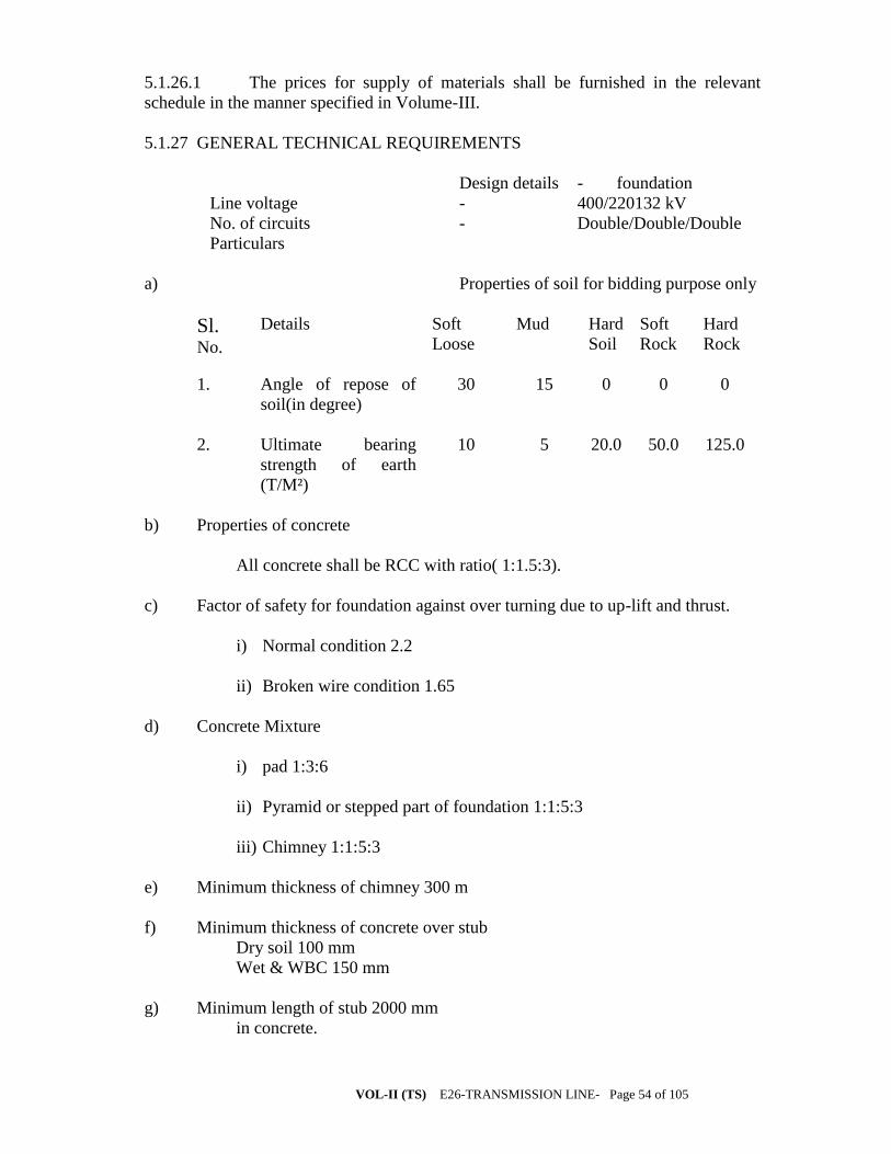
VOL-II (TS) E26-TRANSMISSION LINE- Page 54 of 105
5.1.26.1 The prices for supply of materials shall be furnished in the relevant
schedule in the manner specified in Volume-III.
5.1.27 GENERAL TECHNICAL REQUIREMENTS
Design details - foundation
Line voltage - 400/220132 kV
No. of circuits - Double/Double/Double
Particulars
a) Properties of soil for bidding purpose only
Sl. No.
Details Soft
Loose
Mud Hard
Soil
Soft
Rock
Hard
Rock
1. Angle of repose of
soil(in degree)
30 15 0 0 0
2. Ultimate bearing
strength of earth
(T/M²)
10 5 20.0 50.0 125.0
b) Properties of concrete
All concrete shall be RCC with ratio( 1:1.5:3).
c) Factor of safety for foundation against over turning due to up-lift and thrust.
i) Normal condition 2.2
ii) Broken wire condition 1.65
d) Concrete Mixture
i) pad 1:3:6
ii) Pyramid or stepped part of foundation 1:1:5:3
iii) Chimney 1:1:5:3
e) Minimum thickness of chimney 300 m
f) Minimum thickness of concrete over stub
Dry soil 100 mm
Wet & WBC 150 mm
g) Minimum length of stub 2000 mm
in concrete.

VOL-II (TS) E26-TRANSMISSION LINE- Page 55 of 105
h) Distance above ground level of 450 mm
Tower stub and super structure
5.1.28 .Foundation General Description
5.1.29 Design, construction and other relevant drawings shall be furnished by the
tower designer for all types of towers (including special towers) for different kinds of
soil as detailed below. According to the locations foundations for towers shall be
normally of the following types:
a) Soft/Loose Soil
b) Mud
c) Hard/Dense soil
d) Hard/Disintegrated rock
5.1.30 For rock foundations the holes in rocks shall be made in an approved manner so
as to eliminate the possibility of serious cracking of the rock. The concrete block shall
be properly secured to rock base by adequate no. of anchor bolts and further secured by
concrete lodge section by the sides.
TECHNICAL SPECIFICATION
ERECTION OF
400/220/132 KV D.C. TRANSMISSION LINES
CONSTRUCTION OF TOWER FOUNDATION
AND ERECTION OF TOWER
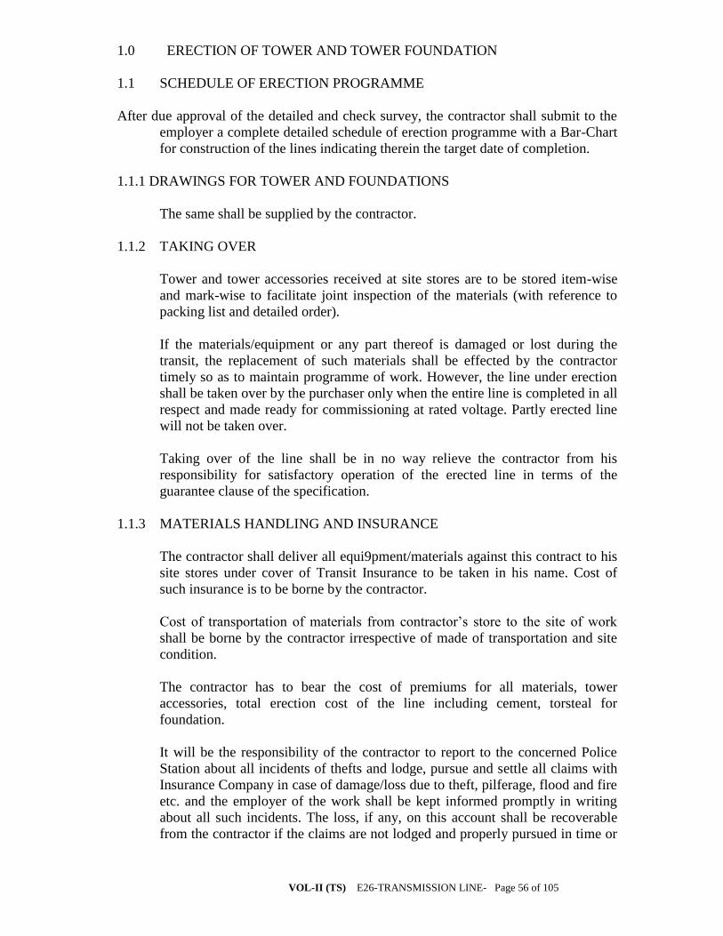
VOL-II (TS) E26-TRANSMISSION LINE- Page 56 of 105
1.0 ERECTION OF TOWER AND TOWER FOUNDATION
1.1 SCHEDULE OF ERECTION PROGRAMME
After due approval of the detailed and check survey, the contractor shall submit to the
employer a complete detailed schedule of erection programme with a Bar-Chart
for construction of the lines indicating therein the target date of completion.
1.1.1 DRAWINGS FOR TOWER AND FOUNDATIONS
The same shall be supplied by the contractor.
1.1.2 TAKING OVER
Tower and tower accessories received at site stores are to be stored item-wise
and mark-wise to facilitate joint inspection of the materials (with reference to
packing list and detailed order).
If the materials/equipment or any part thereof is damaged or lost during the
transit, the replacement of such materials shall be effected by the contractor
timely so as to maintain programme of work. However, the line under erection
shall be taken over by the purchaser only when the entire line is completed in all
respect and made ready for commissioning at rated voltage. Partly erected line
will not be taken over.
Taking over of the line shall be in no way relieve the contractor from his
responsibility for satisfactory operation of the erected line in terms of the
guarantee clause of the specification.
1.1.3 MATERIALS HANDLING AND INSURANCE
The contractor shall deliver all equi9pment/materials against this contract to his
site stores under cover of Transit Insurance to be taken in his name. Cost of
such insurance is to be borne by the contractor.
Cost of transportation of materials from contractor’s store to the site of work
shall be borne by the contractor irrespective of made of transportation and site
condition.
The contractor has to bear the cost of premiums for all materials, tower
accessories, total erection cost of the line including cement, torsteal for
foundation.
It will be the responsibility of the contractor to report to the concerned Police
Station about all incidents of thefts and lodge, pursue and settle all claims with
Insurance Company in case of damage/loss due to theft, pilferage, flood and fire
etc. and the employer of the work shall be kept informed promptly in writing
about all such incidents. The loss, if any, on this account shall be recoverable
from the contractor if the claims are not lodged and properly pursued in time or
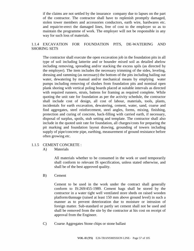
VOL-II (TS) E26-TRANSMISSION LINE- Page 57 of 105
if the claims are not settled by the insurance company due to lapses on the part
of the contractor. The contractor shall have to replenish promptly damaged,
stolen tower members and accessories conductors, earth wire, hardwares etc.
and repair/re-erect the damaged lines, free of cost to the employer so as to
maintain the programme of work. The employer will not be responsible in any
way for such loss of materials.
1.1.4 EXCAVATION FOR FOUNDATION PITS, DE-WATERING AND
SHORING SETS
The contractor shall execute the open excavation job in the foundation pits in all
type of soil including latterite and or bounder mixed soil as detailed abelow
including removing, spreading and/or stacking the excess spils (as directed by
the employer). The item includes the necessary trimming of the sides, leveling,
dressing and ramming (as necessary) the bottom of the pits including bailing out
water, dewatering by manual and/or mechanical means by emplying water
pumps including removing of slushes from foundation pits and nominal open
plank shoring with vertical poling boards placed at suitable intervals as directed
with required runners, struts, battens for framing as required complete. While
quoting the unit rate for foundation as per the activity schedule, the contractor
shall include cost of design, all cost of labour, materials, tools, plants,
incidentals for earth excavation, dewatering, cement, water, sand, coarse and
find aggregates, steel reinforcement, steel angles, forms, mixing, finishing,
protection and curing of concrete, back-filling with carried earth, if necessary,
disposal of surplus, spoils, stub setting and template. The contractor shall also
include in the quoted unit rate for foundation, all charges/costs for preparing the
pit marking and foundation layout drawing, grounding of towers including
supply of pipe/concrete pipe, earthing, measurement of ground resistance before
often growing etc.
1.1.5 CEMENT CONCRETE :
A) Materials
All materials whether to be consumed in the work or used temporarily
shall conform to relevant IS specification, unless stated otherwise, and
shall be of the best approved quality.
B) Cement
Cement to be used in the work under the contract shall generally
conform to IS:269/455-1989. Cement bags shall be stored by the
contractor in a water tight well ventilated store sheds on raised wooden
platform/dunnage (raised at least 150 mm above ground level) in such a
manner as to prevent deterioration due to moisture or intrusion of
foreign matter. Sub-standard or partly set cement shall not be used and
shall be removed from the site by the contractor at his cost on receipt of
approval from the Engineer.
C) Coarse Aggregates Stone chips or stone ballast

VOL-II (TS) E26-TRANSMISSION LINE- Page 58 of 105
D) Reinforcement : Different size of reinforcement(MS ROD-FE-500) as
per latest IS.
Remarks: All foundation of tower shall be of RCC: M20
Grade(1:1.5:3) nominal mix
General Technical Particulars
C. 1 - Span Lengths
132kV 220kV 400kV
Normal span m 300 350 400 Tower design spans: Wind spans: Suspension towers m 300 350 400 Tension towers m 300 350 400 Maximum weight spans: Suspension towers m 450 525 600 Tension towers m 450 525 600 Minimum weight spans: Suspension towers m 100 100 100 Tension towers (uplift net) m -200 -200 -200 (for
DB&DC) -300
(forDD)

VOL-II (TS) E26-TRANSMISSION LINE- Page 59 of 105
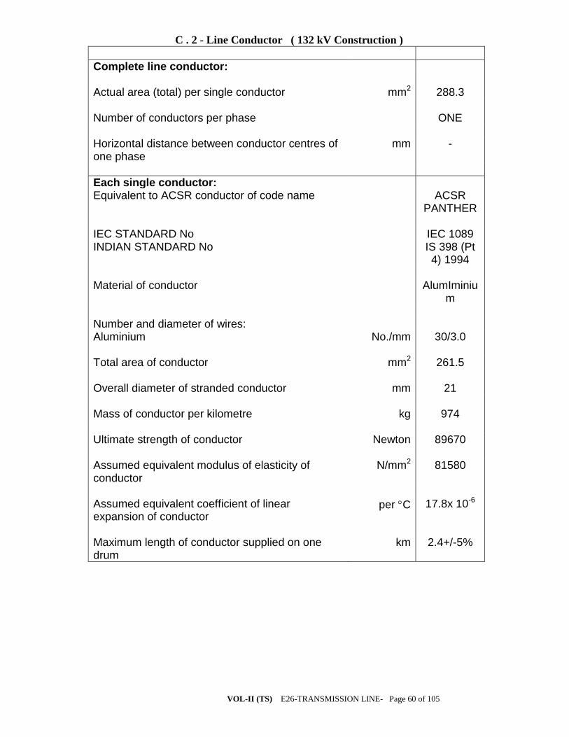
VOL-II (TS) E26-TRANSMISSION LINE- Page 60 of 105
C . 2 - Line Conductor ( 132 kV Construction )
Complete line conductor: Actual area (total) per single conductor mm2 288.3 Number of conductors per phase ONE Horizontal distance between conductor centres of one phase
mm -
Each single conductor: Equivalent to ACSR conductor of code name ACSR
PANTHER IEC STANDARD No IEC 1089 INDIAN STANDARD No IS 398 (Pt
4) 1994 Material of conductor AlumIminiu
m Number and diameter of wires: Aluminium No./mm 30/3.0 Total area of conductor mm2 261.5 Overall diameter of stranded conductor mm 21 Mass of conductor per kilometre kg 974 Ultimate strength of conductor Newton 89670 Assumed equivalent modulus of elasticity of conductor
N/mm2 81580
Assumed equivalent coefficient of linear expansion of conductor
per C 17.8x 10⁻⁶
Maximum length of conductor supplied on one drum
km 2.4+/-5%
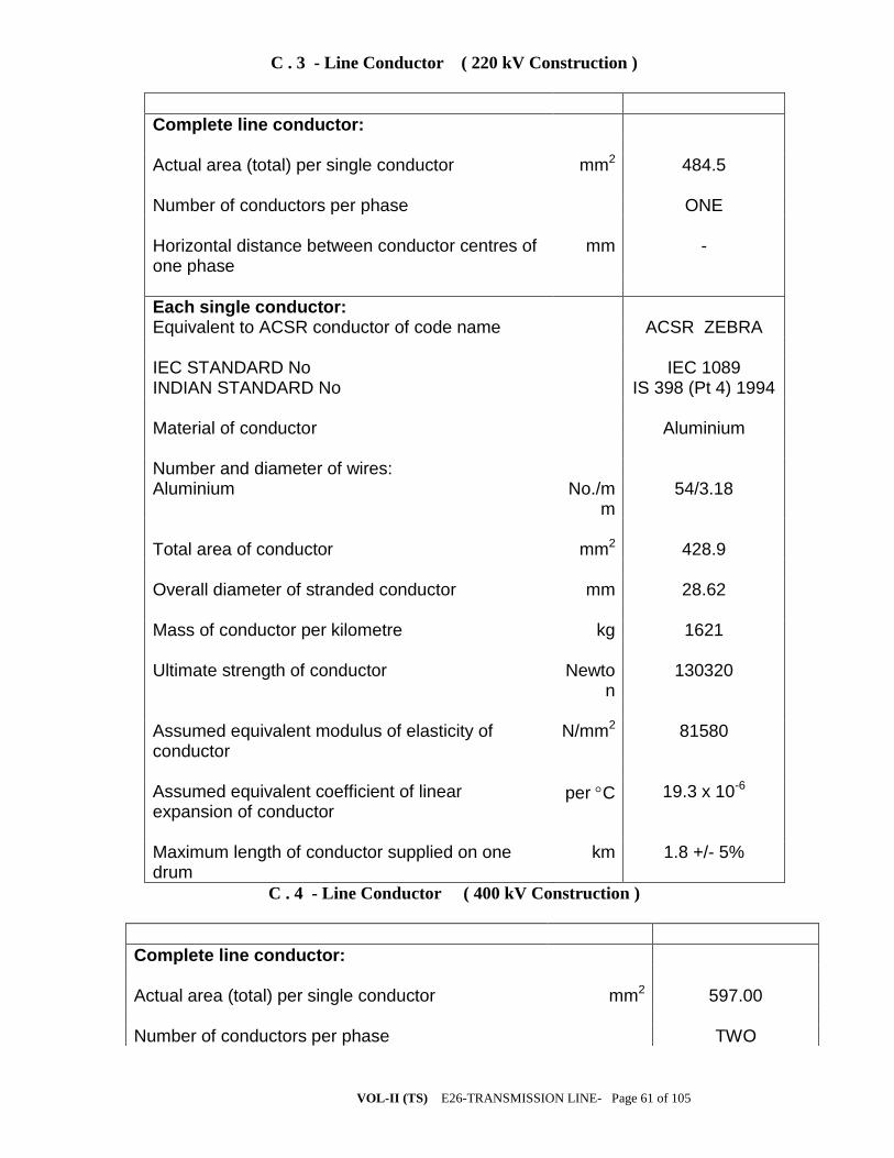
VOL-II (TS) E26-TRANSMISSION LINE- Page 61 of 105
C . 3 - Line Conductor ( 220 kV Construction )
Complete line conductor: Actual area (total) per single conductor mm2 484.5 Number of conductors per phase ONE Horizontal distance between conductor centres of one phase
mm -
Each single conductor: Equivalent to ACSR conductor of code name ACSR ZEBRA IEC STANDARD No IEC 1089 INDIAN STANDARD No IS 398 (Pt 4) 1994 Material of conductor Aluminium Number and diameter of wires: Aluminium No./m
m 54/3.18
Total area of conductor mm2 428.9 Overall diameter of stranded conductor mm 28.62 Mass of conductor per kilometre kg 1621 Ultimate strength of conductor Newto
n 130320
Assumed equivalent modulus of elasticity of conductor
N/mm2 81580
Assumed equivalent coefficient of linear expansion of conductor
per C 19.3 x 10⁻⁶
Maximum length of conductor supplied on one drum
km 1.8 +/- 5%
C . 4 - Line Conductor ( 400 kV Construction )
Complete line conductor: Actual area (total) per single conductor mm2 597.00 Number of conductors per phase TWO

VOL-II (TS) E26-TRANSMISSION LINE- Page 62 of 105
Horizontal distance between conductor centres of one phase
mm 450
Each single conductor: Equivalent to ACSR conductor of code name ACSR MOOSE IEC STANDARD No IEC 1089 INDIAN STANDARD No IS 398 (Pt 4) 1994 Material of conductor Aluminium Number and diameter of wires: Aluminium alloy No./mm 54/3.53 Total area of conductor mm2 597 Overall diameter of stranded conductor mm 31.77 Mass of conductor per kilometre kg 2004 Ultimate strength of conductor Newton 161200 Assumed equivalent modulus of elasticity of conductor
N/mm2 68600
Assumed equivalent coefficient of linear expansion of conductor
per C 19.3 x 10⁻⁶
Maximum length of conductor supplied on one drum km 1.8 +/- 5%
**ALL THE CONDUCTORS ARE ACSR CONDUCTORS HAVING 7
STRANDS OF GI STEEL WIRE.

VOL-II (TS) E26-TRANSMISSION LINE- Page 63 of 105
C . 5 - Earth Wire (132 kV And 220 kV Constructions)
GSW
Complete earth conductor: Appropriate Indian Standard No 398(Part-2) Appropriate British Standard No 183 Material of conductor galvanised steel Number and diameter of wires No./m
m 7/3.15
Overall diameter of conductor mm 9.45 Mass of conductor per kilometre kg 428 Ultimate strength of conductor Newto
n 56000
Lay length mm 160 +/- 15 Direction of the lay of the outer layer Right hand Chemical composition of the steel wire % Carbon not more than 0.55 Manganese 0.4 to 0.9 Phosphorous not more than 0.04 Sulphur not more than 0.04 Silicon 0.15 to 0.35 Purity of Zinc for galvanising % 99.95 Galvanising after stranding a) Minimum weight of Zinc coating per sq. m. of the uncoated wire surface
gms 240
b) Minimum no. of one minute dips that the galvanised wire can withstand in Standard Preece Test
3 and 1/2
Maximum length of conductor on drum # km 4 +/- 5% D.C. resistance at 20 o C ohms/k
m 3.375
C . 6 - Earth Wire (400 kV Construction )
GSW
Complete earth conductor:

VOL-II (TS) E26-TRANSMISSION LINE- Page 64 of 105
Appropriate Indian Standard No 398(Part-2) Appropriate British Standard No 183 Material of conductor galvanised steel Number and diameter of wires No./mm 7/3.66 Overall diameter of conductor mm 10.98 Mass of conductor per kilometre kg 583 Ultimate strength of conductor Newton 68400 Lay length mm 160 +/- 15 Direction of the lay of the outer layer Right hand Chemical composition of the steel wire % Carbon not more than 0.55 Manganese 0.4 to 0.9 Phosphorous not more than 0.04 Sulphur not more than 0.04 Silicon 0.15 to 0.35 Purity of Zinc for galvanising % 99.95 Galvanising after stranding a) Minimum weight of Zinc coating per sq. m. of the uncoated wire surface
gms 240
b) Minimum no. of one minute dips that the galvanised wire can withstand in Standard Preece Test
3 and 1/2
Maximum length of conductor on drum # km 4 +/- 5% D.C. resistance of the complete earthwire at 20OC ohms/k
m 2.5
C.14 * - Disc Insulator Units ( Anti-Fog Type )
70kN 90kN 120kN 160kN
Size and designation of the ball pin shank
mm 16 16 20 20
Diameter of the disc mm 280/305 280/305 280/305 280/305 Tolerance on the diameter +/-mm 13/15 13/15 13/15 13/15

VOL-II (TS) E26-TRANSMISSION LINE- Page 65 of 105
Ball to ball spacing between disc
mm 145 145 145 170
Tolerance on ball to ball spacing
+/-mm 4 4 4 5
Minimum creepage distance of a single disc **
mm 430 430 430 475
Steepness of the impulse voltage which the disc unit can withstand in Steep Wave Front Test
kV per micro
sec.
2500 2500 2500 2500
Purity of Zinc used for galvanising
% 99.95 99.95 99.95 99.95
Purity of Zinc used for sleeve % 99.7 99.7 99.7 99.7 No. of dips in Standard Preece Test 1) Cap socket 2) Ball pin
6 6
6 6
6 6
6 6
*The parameters specified are for disc insulator unit only. For the Bids offering
composite insulator units, the parameters may be suitably selected by the Bidder
so as to meet the overall requirements of the respective strings and same shall be
guaranteed at Schedules 13A and 14A of the Technical Data Requirement
Schedules, Section X.
** The minimum creepage distance of single composite insulator unit shall be such
that it matches with the total creepage distance of the respective strings with disc
insulator units.
C . 15 - Insulator Strings (Suspension Sets For 132 kV Lines )
Single “I” Suspensio
n Strings
Double “I” Suspensio
n Strings
Pilot Suspension
Strings
Power frequency withstand voltage of the string with arcing horns and corona control rings / grading rings under wet conditions
kV(rms) 275 275 275
Impulse withstand voltage
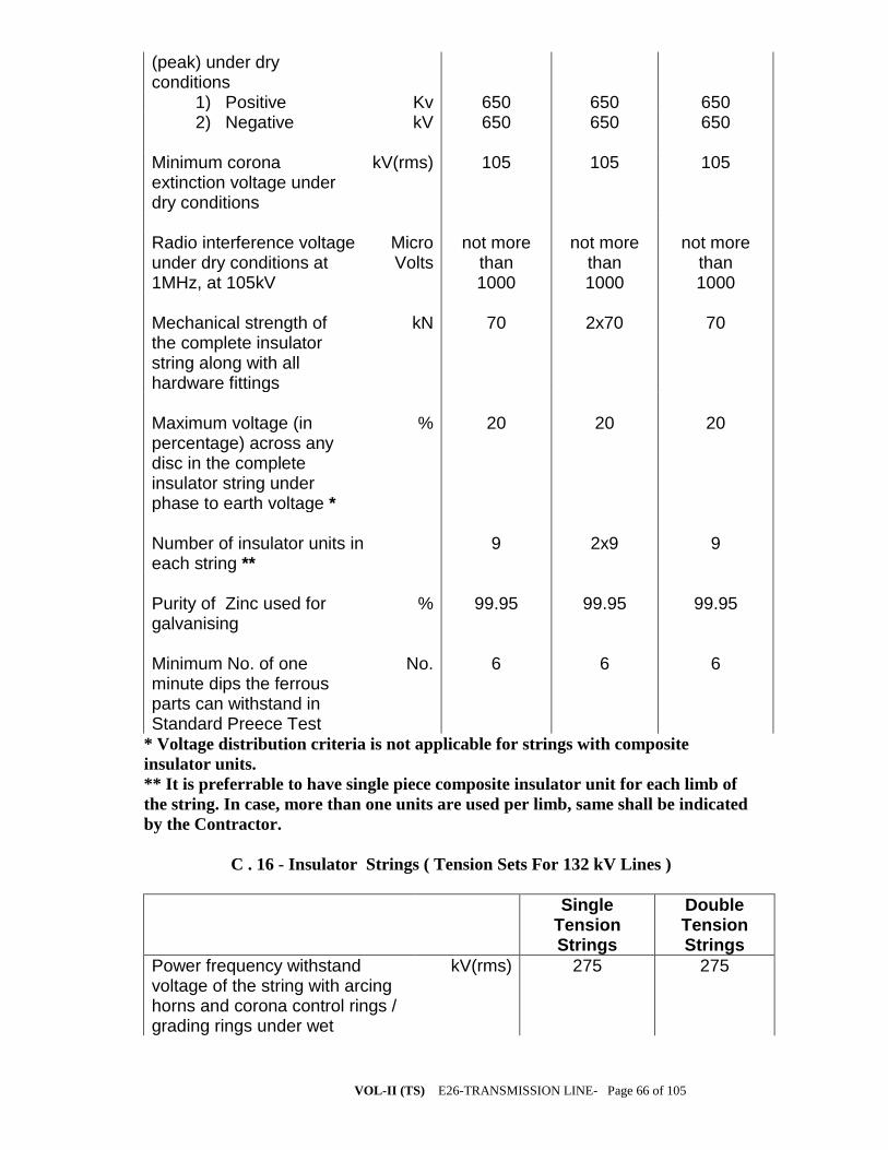
VOL-II (TS) E26-TRANSMISSION LINE- Page 66 of 105
(peak) under dry conditions 1) Positive Kv 650 650 650 2) Negative kV 650 650 650 Minimum corona extinction voltage under dry conditions
kV(rms) 105 105 105
Radio interference voltage under dry conditions at 1MHz, at 105kV
Micro Volts
not more than 1000
not more than 1000
not more than 1000
Mechanical strength of the complete insulator string along with all hardware fittings
kN 70 2x70 70
Maximum voltage (in percentage) across any disc in the complete insulator string under phase to earth voltage *
% 20 20 20
Number of insulator units in each string **
9 2x9 9
Purity of Zinc used for galvanising
% 99.95 99.95 99.95
Minimum No. of one minute dips the ferrous parts can withstand in Standard Preece Test
No. 6 6 6
* Voltage distribution criteria is not applicable for strings with composite
insulator units.
** It is preferrable to have single piece composite insulator unit for each limb of
the string. In case, more than one units are used per limb, same shall be indicated
by the Contractor.
C . 16 - Insulator Strings ( Tension Sets For 132 kV Lines )
Single Tension Strings
Double Tension Strings
Power frequency withstand voltage of the string with arcing horns and corona control rings / grading rings under wet
kV(rms) 275 275
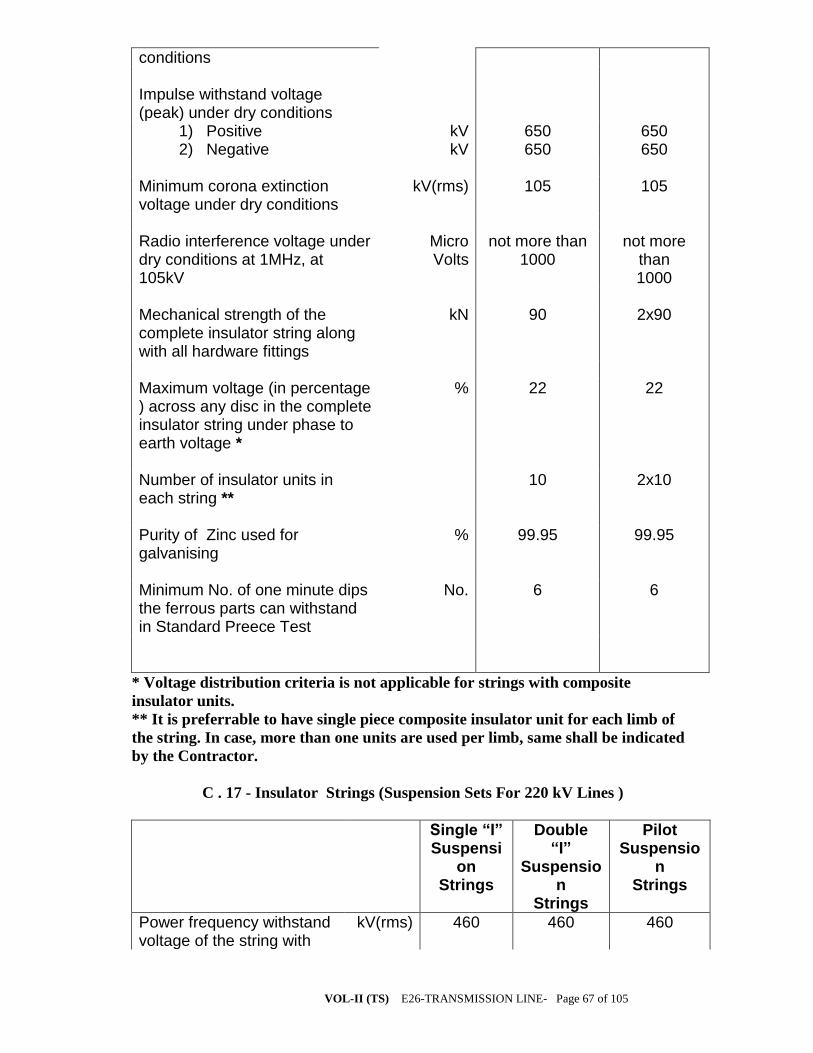
VOL-II (TS) E26-TRANSMISSION LINE- Page 67 of 105
conditions Impulse withstand voltage (peak) under dry conditions
1) Positive kV 650 650 2) Negative kV 650 650 Minimum corona extinction voltage under dry conditions
kV(rms) 105 105
Radio interference voltage under dry conditions at 1MHz, at 105kV
Micro Volts
not more than 1000
not more than 1000
Mechanical strength of the complete insulator string along with all hardware fittings
kN 90 2x90
Maximum voltage (in percentage ) across any disc in the complete insulator string under phase to earth voltage *
% 22 22
Number of insulator units in each string **
10 2x10
Purity of Zinc used for galvanising
% 99.95 99.95
Minimum No. of one minute dips the ferrous parts can withstand in Standard Preece Test
No. 6 6
* Voltage distribution criteria is not applicable for strings with composite
insulator units.
** It is preferrable to have single piece composite insulator unit for each limb of
the string. In case, more than one units are used per limb, same shall be indicated
by the Contractor.
C . 17 - Insulator Strings (Suspension Sets For 220 kV Lines )
Single “I” Suspensi
on Strings
Double “I”
Suspension
Strings
Pilot Suspensio
n Strings
Power frequency withstand voltage of the string with
kV(rms) 460 460 460

VOL-II (TS) E26-TRANSMISSION LINE- Page 68 of 105
arcing horns and corona control rings / grading rings under wet conditions Impulse withstand voltage (peak) under dry conditions
1) Positive kV 1050 1050 1050 2) Negative kV 1050 1050 1050 Minimum corona extinction voltage under dry conditions
kV(rms) 154 154 154
Radio interference voltage under dry conditions at 1MHz, at 154kV
Micro Volts
not more than 1000
not more than 1000
not more than 1000
Mechanical strength of the complete insulator string along with all hardware fittings
kN 70 2x70 70
Maximum voltage (in percentage ) across any disc in the complete insulator string under phase to earth voltage *
% 13 13 13
Number of insulator units in each string**
14 2x14 14
Purity of Zinc used for galvanising
% 99.95 99.95 99.95
Minimum No. of one minute dips the ferrous parts can withstand in Standard Preece Test
No. 6 6 6
* Voltage distribution criteria is not applicable for strings with composite
insulator units.
** It is preferrable to have single piece composite insulator unit for each limb of
the string. In case, more than one units are used per limb, same shall be indicated
by the Contractor.
C . 18 - Insulator Strings ( Tension Sets For 220 kV Lines )
Single Tension Strings
Double Tension Strings
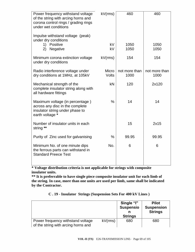
VOL-II (TS) E26-TRANSMISSION LINE- Page 69 of 105
Power frequency withstand voltage of the string with arcing horns and corona control rings / grading rings under wet conditions
kV(rms) 460 460
Impulse withstand voltage (peak) under dry conditions
1) Positive kV 1050 1050 2) Negative kV 1050 1050 Minimum corona extinction voltage under dry conditions
kV(rms) 154 154
Radio interference voltage under dry conditions at 1MHz, at 105kV
Micro Volts
not more than 1000
not more than 1000
Mechanical strength of the complete insulator string along with all hardware fittings
kN 120 2x120
Maximum voltage (in percentage ) across any disc in the complete insulator string under phase to earth voltage *
% 14 14
Number of insulator units in each string **
15 2x15
Purity of Zinc used for galvanising % 99.95 99.95 Minimum No. of one minute dips the ferrous parts can withstand in Standard Preece Test
No. 6 6
* Voltage distribution criteria is not applicable for strings with composite
insulator units.
** It is preferrable to have single piece composite insulator unit for each limb of
the string. In case, more than one units are used per limb, same shall be indicated
by the Contractor.
C . 19 - Insulator Strings (Suspension Sets For 400 kV Lines )
Single “I” Suspensio
n Strings
Pilot Suspension
Strings
Power frequency withstand voltage of the string with arcing horns and
kV(rms) 680 680
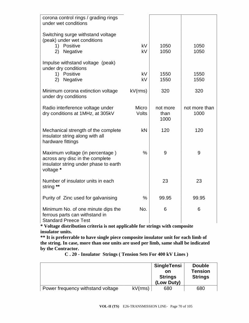
VOL-II (TS) E26-TRANSMISSION LINE- Page 70 of 105
corona control rings / grading rings under wet conditions Switching surge withstand voltage (peak) under wet conditions
1) Positive kV 1050 1050 2) Negative kV 1050 1050 Impulse withstand voltage (peak) under dry conditions
1) Positive kV 1550 1550 2) Negative kV 1550 1550 Minimum corona extinction voltage under dry conditions
kV(rms) 320 320
Radio interference voltage under dry conditions at 1MHz, at 305kV
Micro Volts
not more than 1000
not more than 1000
Mechanical strength of the complete insulator string along with all hardware fittings
kN 120 120
Maximum voltage (in percentage ) across any disc in the complete insulator string under phase to earth voltage *
% 9 9
Number of insulator units in each string **
23 23
Purity of Zinc used for galvanising % 99.95 99.95 Minimum No. of one minute dips the ferrous parts can withstand in Standard Preece Test
No. 6 6
* Voltage distribution criteria is not applicable for strings with composite
insulator units.
** It is preferrable to have single piece composite insulator unit for each limb of
the string. In case, more than one units are used per limb, same shall be indicated
by the Contractor.
C . 20 - Insulator Strings ( Tension Sets For 400 kV Lines )
SingleTension
Strings (Low Duty)
Double Tension Strings
Power frequency withstand voltage kV(rms) 680 680

VOL-II (TS) E26-TRANSMISSION LINE- Page 71 of 105
of the string with arcing horns and corona control rings / grading rings under wet conditions Switching surge withstand voltage (peak) under wet conditions
1) Positive kV 1050 1050 2) Negative kV 1050 1050 Impulse withstand voltage (peak) under dry conditions
1) Positive kV 1550 1550 2) Negative kV 1550 1550 Minimum corona extinction voltage under dry conditions
kV(rms) 320 320
Radio interference voltage under dry conditions at 1MHz, at 305kV
Micro Volts
not more than 1000
not more than 1000
Mechanical strength of the complete insulator string along with all hardware fittings
kN 120 2x160
Maximum voltage (in percentage ) across any disc in the complete insulator string under phase to earth voltage *
% 10 10
Number of insulator units in each string **
24 2x23
Purity of Zinc used for galvanising % 99.95 99.95 Minimum No. of one minute dips the ferrous parts can withstand in Standard Preece Test
No. 6 6
* Voltage distribution criteria is not applicable for strings with composite
insulator units.
** It is preferrable to have single piece composite insulator unit for each limb of
the string. In case, more than one units are used per limb, same shall be indicated
by the Contractor.
C . 21 - Tower Design Particulars (132 kV Construction)
Minimum clearance between live metal and tower steelwork:

VOL-II (TS) E26-TRANSMISSION LINE- Page 72 of 105
i.with suspension insulator set swing 0° mm 1530 with suspension insulator set swing 15° mm 1530 with suspension insulator set swing 30° mm 1370 with suspension insulator set swing 45° mm 1220 with suspension insulator set swing 60° mm 1070 ii.with jumper loop swing 0° mm 1530 with jumper loop swing 10° mm 1530 with jumper loop swing 20° mm 1070 with jumper loop swing 30° mm 1070 with jumper loop swing 40° mm - Insulator suspension set, unobstructed transverse swing angle
from vertical degrees 0 - 60 Earth conductor suspension clamps, unobstructed transverse
swing angle from vertical degrees 0 - 50 Earth conductor maximum shielding angle from vertical at
tower attachment point over outer line conductors
degrees 30
C . 22 - Tower Design Particulars (220 kV Construction)
Minimum clearance between live metal and tower steelwork:
i. with suspension insulator set swing 0° mm 2130 with suspension insulator set swing 15° mm 1980 with suspension insulator set swing 30° mm 1830 with suspension insulator set swing 45° mm 1675 with suspension insulator set swing 60° mm - ii. with jumper loop swing 0° mm 2130

VOL-II (TS) E26-TRANSMISSION LINE- Page 73 of 105
with jumper loop swing 10° mm 1675 with jumper loop swing 20° mm 1675 with jumper loop swing 30° mm - with jumper loop swing 40° mm - Insulator suspension set, unobstructed transverse swing angle
from vertical degrees 0 - 45 Earth conductor suspension clamps, unobstructed transverse
swing angle from vertical degrees 0 - 50 Earth conductor maximum shielding angle from vertical at
tower attachment point over outer line conductors
degrees 30

VOL-II (TS) E26-TRANSMISSION LINE- Page 74 of 105
C . 23 - Tower Design Particulars (400 kV Construction)
Minimum clearance between live metal and tower steelwork:
i. with suspension insulator set swing 0° mm 3050 with suspension insulator set swing 15° mm 3050 with suspension insulator set swing 30° mm 1860 with suspension insulator set swing 45° mm - with suspension insulator set swing 60° mm - ii. with jumper loop swing 0° mm 3050 with jumper loop swing 10° mm 3050 with jumper loop swing 20° mm 3050 with jumper loop swing 30° mm 1860 with jumper loop swing 40° mm 1860 Insulator suspension set, unobstructed transverse swing angle
from vertical degrees 0 - 30 Earth conductor suspension clamps, unobstructed transverse
swing angle from vertical degrees 0 - 50 Earth conductor maximum shielding angle from vertical at
tower attachment point over outer line conductors degrees 20
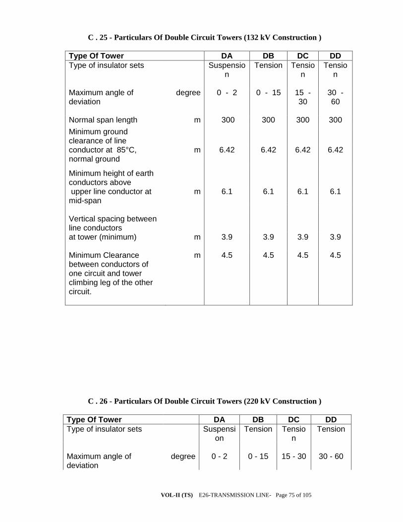
VOL-II (TS) E26-TRANSMISSION LINE- Page 75 of 105
C . 25 - Particulars Of Double Circuit Towers (132 kV Construction )
Type Of Tower DA DB DC DD
Type of insulator sets Suspension
Tension Tension
Tension
Maximum angle of deviation
degree 0 - 2 0 - 15 15 - 30
30 - 60
Normal span length m 300 300 300 300 Minimum ground clearance of line
conductor at 85°C, normal ground
m 6.42 6.42 6.42 6.42
Minimum height of earth conductors above
upper line conductor at mid-span
m 6.1 6.1 6.1 6.1
Vertical spacing between line conductors
at tower (minimum) m 3.9 3.9 3.9 3.9 Minimum Clearance between conductors of one circuit and tower climbing leg of the other circuit.
m 4.5 4.5 4.5 4.5
C . 26 - Particulars Of Double Circuit Towers (220 kV Construction )
Type Of Tower DA DB DC DD
Type of insulator sets Suspension
Tension Tension
Tension
Maximum angle of deviation
degree 0 - 2 0 - 15 15 - 30 30 - 60

VOL-II (TS) E26-TRANSMISSION LINE- Page 76 of 105
Normal span length m 350 350 350 350 Minimum ground clearance of line
conductor at 85 °C, normal ground
m 7.23 7.23 7.23 7.23
Minimum height of earth conductors above
upper line conductor at mid-span
m 8.5 8.5 8.5 8.5
Vertical spacing between line conductors
at tower (minimum) m 4.9 4.9 4.9 4.9 Minimum Clearance between conductors of one circuit and tower climbing leg of the other circuit.
m 5.5 5.5 5.5 5.5
C . 27 - Particulars Of Double Circuit Towers ( 400 kV Construction )
Type Of Tower DA DB DC DD
Type of insulator sets Suspension
Tension Tension Tension
Maximum angle of deviation
degree 0 - 2 0 - 15 15 - 30 30 - 60
Normal span length m 400 400 400 400 Minimum ground clearance of line
conductor at 85 °C, normal ground
m 8.84 8.84 8.84 8.84
Minimum height of earth conductors above
upper line conductor m 9.0 9.0 9.0 9.0

VOL-II (TS) E26-TRANSMISSION LINE- Page 77 of 105
at mid-span Vertical spacing between line conductors
at tower (minimum ) . m 8.0 8.0 8.0 8.0 Minimum Clearance between conductors of one circuit and tower climbing leg of the other circuit.
m 6.5 6.5 6.5 6.5
C . 28 - Foundation Design Particulars
Assumed density of Plain Cement Concrete (PCC) for foundation in dry soil
kg/m3 2240
Assumed density of Plain Cement Concrete (PCC) for foundation in presence of sub-soil water
kg/m3 1240
Assumed density of Re-inforced Cement Concrete (RCC) for foundation in dry soil
kg/m3 2400
Assumed density of Re-inforced Cement Concrete (RCC) for foundation in presence of sub-soil water
kg/m3 1400
28 day concrete cube strength (characteristic strength for M-20 concrete)
N/mm2 20
28 day concrete cube strength (characteristic strength for M-15 concrete)
N/mm2 15
Minimum proportion of stub load to be allowed for in the design of stub cleats
% 100
Density of all type of soils : 1) under dry conditions kg/m3 1440 2) in presence of surface water kg/m3 1440 3) in presence of sub-soil water kg/m3 840 Ultimate bearing capacity of the soil : 1) normal soil under dry condition kN/m2 214 2) normal soil in presence of surface as well as kN/m2 107

VOL-II (TS) E26-TRANSMISSION LINE- Page 78 of 105
sub-soil water 3) wet black cotton soil kN/m2 107 4) fissured rock ( both for dry and wet ) kN/m2 400 5) hard rock kN/m2 750 Angle of repose for : 1) dry soil Degree 30 2) wet soil due to presence of surface/ sub-soil water
Degree 15
3) wet black cotton soil Degree 0 4) dry fissured rock Degree 20 5) wet fissured rock Degree 10 Ultimate bond between steel and concrete kN/m2 0.147
Note : All the soil parameters furnished above are subject to verification by actual soil
investigations. The Contractor shall be required to carry-out field test for each type of
foundation, as per the quoted rates in Price Schedules, to prove the design parameters
considered.
The foundation classification criteria shall be as given below, depending upon type of
soil and sub-soil water level / presence of surface water :
Normal Dry : To be used for locations where normal dry cohesive or non-cohesive soils
are met without encountering sub-soil water table within the depth of foundation.
Wet : To be used for locations,
a) where sub-soil water is met at 1.5 m. or more below the ground level;
b) which are in surface water for long periods with water penetration not
exceeding one metre below the ground level e.g. , the paddy field.
Partially Submerged : To be used for the locations where sub-soil water table is met
between 0.75 to 1.5 m. below the ground level;
Fully Submerged : To be used for locations where sub-soil water table is met at less
than 0.75 m. below the ground level;
Black Cotton Type : To be used at locations where soil is clayey type, not necessarily
black in colour, which shrinks when dry and swells when wet, resulting in differential
movement. For designing the foundation for such locations, the soil is to be considered
as fully submerged.
Fissured Rock : To be used at locations where decomposed or fissured rock, hard
gravel, kankar, lime-stone, laterite or any other soil of similar nature is met. Under-cut
type foundation is to be used for such locations.
In case of fissured rock locations where water table is met at 1.5 m. or more below
ground level, wet type fissured rock foundations shall be adopted.
Hard Rock : To be used for the locations where chiselling, drilling or blasting is
required for excavation . For these locations rock anchoring is to be provided to resist
the uplift forces.
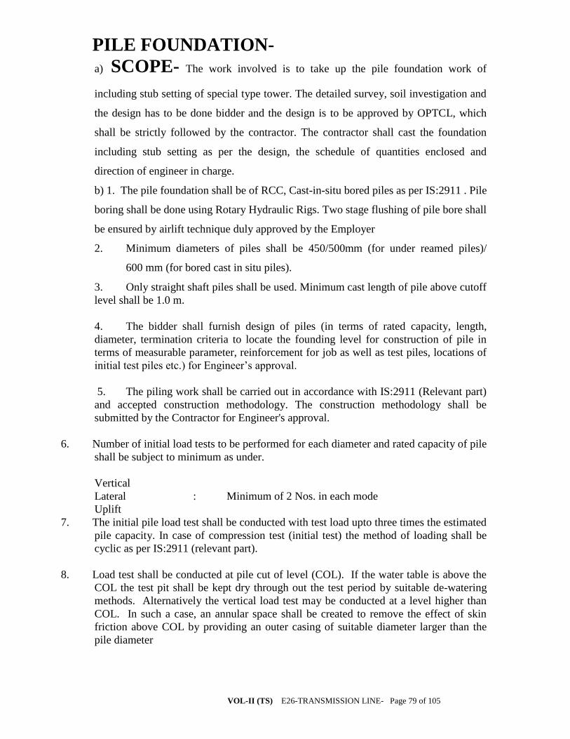
VOL-II (TS) E26-TRANSMISSION LINE- Page 79 of 105
PILE FOUNDATION-
a) SCOPE- The work involved is to take up the pile foundation work of
including stub setting of special type tower. The detailed survey, soil investigation and
the design has to be done bidder and the design is to be approved by OPTCL, which
shall be strictly followed by the contractor. The contractor shall cast the foundation
including stub setting as per the design, the schedule of quantities enclosed and
direction of engineer in charge.
b) 1. The pile foundation shall be of RCC, Cast-in-situ bored piles as per IS:2911 . Pile
boring shall be done using Rotary Hydraulic Rigs. Two stage flushing of pile bore shall
be ensured by airlift technique duly approved by the Employer
2. Minimum diameters of piles shall be 450/500mm (for under reamed piles)/
600 mm (for bored cast in situ piles).
3. Only straight shaft piles shall be used. Minimum cast length of pile above cutoff
level shall be 1.0 m.
4. The bidder shall furnish design of piles (in terms of rated capacity, length,
diameter, termination criteria to locate the founding level for construction of pile in
terms of measurable parameter, reinforcement for job as well as test piles, locations of
initial test piles etc.) for Engineer’s approval.
5. The piling work shall be carried out in accordance with IS:2911 (Relevant part)
and accepted construction methodology. The construction methodology shall be
submitted by the Contractor for Engineer's approval.
6. Number of initial load tests to be performed for each diameter and rated capacity of pile
shall be subject to minimum as under.
Vertical
Lateral : Minimum of 2 Nos. in each mode
Uplift
7. The initial pile load test shall be conducted with test load upto three times the estimated
pile capacity. In case of compression test (initial test) the method of loading shall be
cyclic as per IS:2911 (relevant part).
8. Load test shall be conducted at pile cut of level (COL). If the water table is above the
COL the test pit shall be kept dry through out the test period by suitable de-watering
methods. Alternatively the vertical load test may be conducted at a level higher than
COL. In such a case, an annular space shall be created to remove the effect of skin
friction above COL by providing an outer casing of suitable diameter larger than the
pile diameter
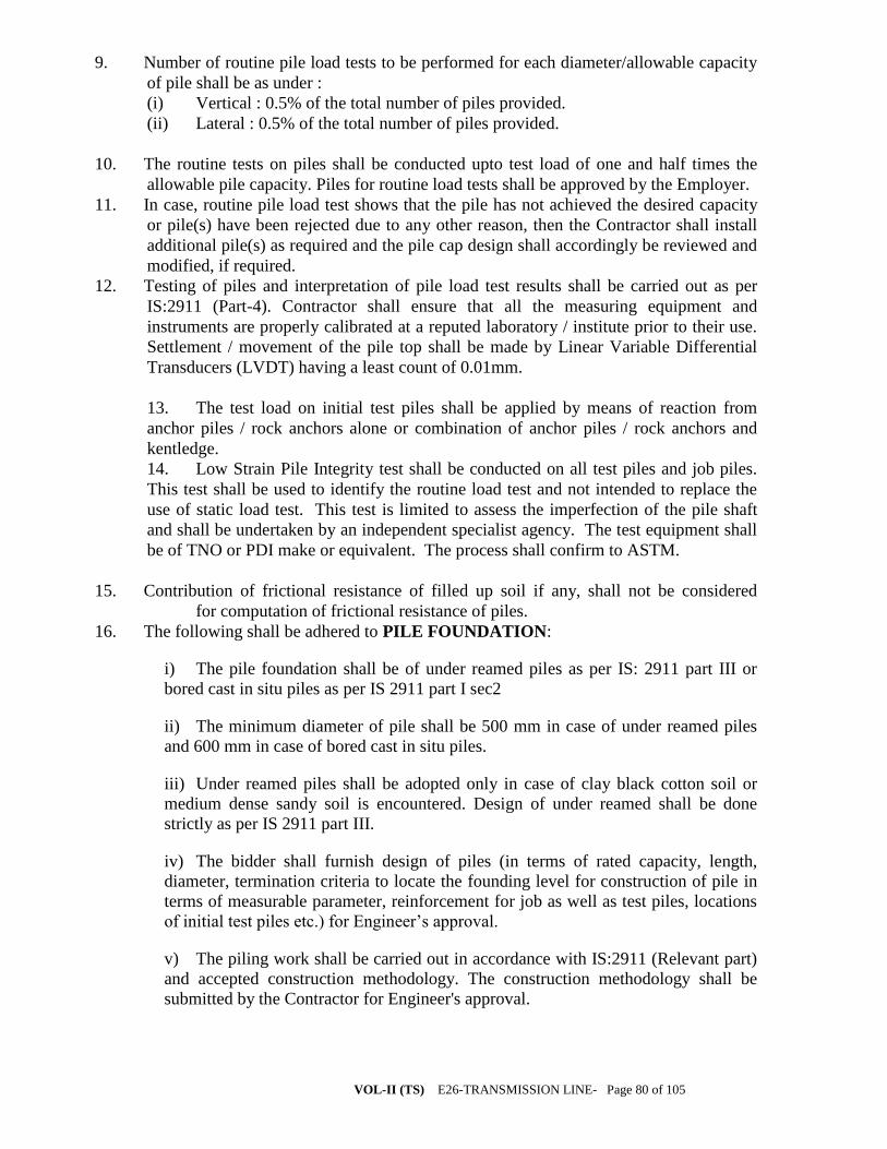
VOL-II (TS) E26-TRANSMISSION LINE- Page 80 of 105
9. Number of routine pile load tests to be performed for each diameter/allowable capacity
of pile shall be as under :
(i) Vertical : 0.5% of the total number of piles provided.
(ii) Lateral : 0.5% of the total number of piles provided.
10. The routine tests on piles shall be conducted upto test load of one and half times the
allowable pile capacity. Piles for routine load tests shall be approved by the Employer.
11. In case, routine pile load test shows that the pile has not achieved the desired capacity
or pile(s) have been rejected due to any other reason, then the Contractor shall install
additional pile(s) as required and the pile cap design shall accordingly be reviewed and
modified, if required.
12. Testing of piles and interpretation of pile load test results shall be carried out as per
IS:2911 (Part-4). Contractor shall ensure that all the measuring equipment and
instruments are properly calibrated at a reputed laboratory / institute prior to their use.
Settlement / movement of the pile top shall be made by Linear Variable Differential
Transducers (LVDT) having a least count of 0.01mm.
13. The test load on initial test piles shall be applied by means of reaction from
anchor piles / rock anchors alone or combination of anchor piles / rock anchors and
kentledge.
14. Low Strain Pile Integrity test shall be conducted on all test piles and job piles.
This test shall be used to identify the routine load test and not intended to replace the
use of static load test. This test is limited to assess the imperfection of the pile shaft
and shall be undertaken by an independent specialist agency. The test equipment shall
be of TNO or PDI make or equivalent. The process shall confirm to ASTM.
15. Contribution of frictional resistance of filled up soil if any, shall not be considered
for computation of frictional resistance of piles.
16. The following shall be adhered to PILE FOUNDATION:
i) The pile foundation shall be of under reamed piles as per IS: 2911 part III or
bored cast in situ piles as per IS 2911 part I sec2
ii) The minimum diameter of pile shall be 500 mm in case of under reamed piles
and 600 mm in case of bored cast in situ piles.
iii) Under reamed piles shall be adopted only in case of clay black cotton soil or
medium dense sandy soil is encountered. Design of under reamed shall be done
strictly as per IS 2911 part III.
iv) The bidder shall furnish design of piles (in terms of rated capacity, length,
diameter, termination criteria to locate the founding level for construction of pile in
terms of measurable parameter, reinforcement for job as well as test piles, locations
of initial test piles etc.) for Engineer’s approval.
v) The piling work shall be carried out in accordance with IS:2911 (Relevant part)
and accepted construction methodology. The construction methodology shall be
submitted by the Contractor for Engineer's approval.

VOL-II (TS) E26-TRANSMISSION LINE- Page 81 of 105
vi) Number of initial load tests to be performed for each diameter and rated
capacity of pile shall be subject to minimum as under.
Vertical
Lateral Minimum of 2 Nos. in each mode.
Uplift
vii) The initial pile load test shall be conducted with test load upto three times the
estimated pile capacity. In case of compression test (initial test) the method of
loading shall be cyclic as per IS:2911 (part IV).
viii) Load test shall be conducted at pile cut of level (COL). If the water table is
above the COL the test pit shall be kept dry through out the test period by suitable
de-watering methods. Alternatively the vertical load test may be conducted at a
level higher than COL. In such a case, an annular space shall be created to remove
the effect of skin friction above COL by providing an outer casing of suitable
diameter larger than the pile diameter.
ix) Number of routine pile load tests to be performed for each diameter/allowable
capacity of pile shall be as under :
i) Vertical : 0.5% of the total number of piles provided.
ii) Lateral : 0.5% of the total number of piles provided.
x) The routine tests on piles shall be conducted upto test load of one and half times
the allowable pile capacity. Piles for routine load tests shall be approved by the
Employer.
xi) In case, routine pile load test shows that the pile has not achieved the desired
capacity or pile(s) have been rejected due to any other reason, then the Contractor
shall install additional pile(s) as required and the pile cap design shall accordingly be
reviewed and modified, if required.
xii) Testing of piles and interpretation of pile load test results shall be carried out as
per IS:2911 (Part-4). Contractor shall ensure that all the measuring equipment and
instruments are properly calibrated at a reputed laboratory / institute prior to their
use. Settlement / movement of the pile top shall be made by Linear Variable
Differential Transducers (LVDT) having a least count of 0.01mm.
xiii) The test load on initial test piles shall be applied by means of reaction from
anchor piles / rock anchors alone or combination of anchor piles / rock anchors and
kentledge.
xiv) Contribution of frictional resistance of filled up soil if any, shall not be
considered for computation of frictional resistance of piles.
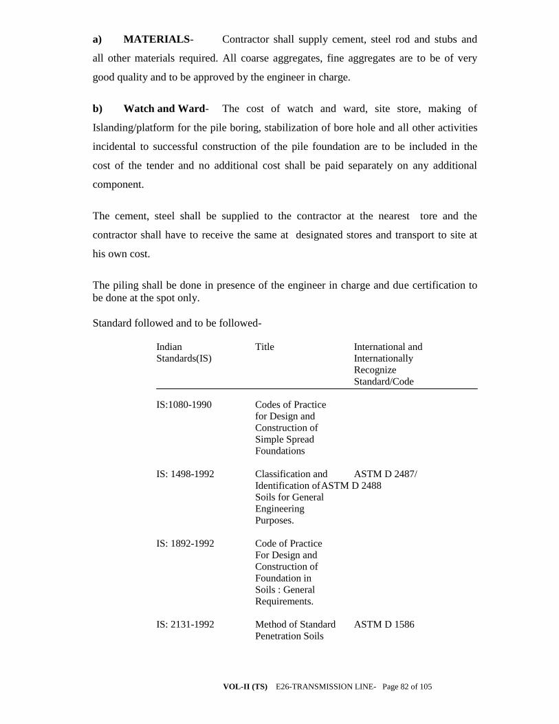
VOL-II (TS) E26-TRANSMISSION LINE- Page 82 of 105
a) MATERIALS- Contractor shall supply cement, steel rod and stubs and
all other materials required. All coarse aggregates, fine aggregates are to be of very
good quality and to be approved by the engineer in charge.
b) Watch and Ward- The cost of watch and ward, site store, making of
Islanding/platform for the pile boring, stabilization of bore hole and all other activities
incidental to successful construction of the pile foundation are to be included in the
cost of the tender and no additional cost shall be paid separately on any additional
component.
The cement, steel shall be supplied to the contractor at the nearest tore and the
contractor shall have to receive the same at designated stores and transport to site at
his own cost.
The piling shall be done in presence of the engineer in charge and due certification to
be done at the spot only.
Standard followed and to be followed-
Indian Title International and
Standards(IS) Internationally
Recognize
Standard/Code
IS:1080-1990 Codes of Practice
for Design and
Construction of
Simple Spread
Foundations
IS: 1498-1992 Classification and ASTM D 2487/
Identification of ASTM D 2488
Soils for General
Engineering
Purposes.
IS: 1892-1992 Code of Practice
For Design and
Construction of
Foundation in
Soils : General
Requirements.
IS: 2131-1992 Method of Standard ASTM D 1586
Penetration Soils

VOL-II (TS) E26-TRANSMISSION LINE- Page 83 of 105
IS: 2132-1992 Code of Practice ASTM D 1587
For Thin Walled
Sampling of Soils
IS: 2720-1992 Method of Test ASTM D 420
For Soils (Rele-
vant Parts.
IS: 2809-1991 Glossary of Terms ASTM D 653
And symbols
Relating to Soil
Engineering
Indian Title International and
Standards(IS) Internationally
Recognize
Standard/Code
IS: 2911-1980 Code of Practice
For Design and
Construction of
Pile Foundations
(Relevant Parts).
IS: 3025 Methods of Sampling
And Testing (Physical
And Chemical) for
Water used in industry.
IS: 3043-1991 Code or Practice for
Indexing and Storage
Of Drill Cores.
IS: 4091-1987 Code of Practice for
Design and Construction
Of Foundations for
Transmission Line Towers
and Poles.
IS: 4434-1992 Code of Practice for ASTM D 2573/
in-situ Vane Shear ASTM D 4648
Test for Soils.
IS: 4453-1992 Code of Practice for
Exploration by Pits,
Trenches, Drifts and
Shafts.
IS: 4464-1990 Code of Practice for
Presentation of Drilling
Information and core
Description in Foundation
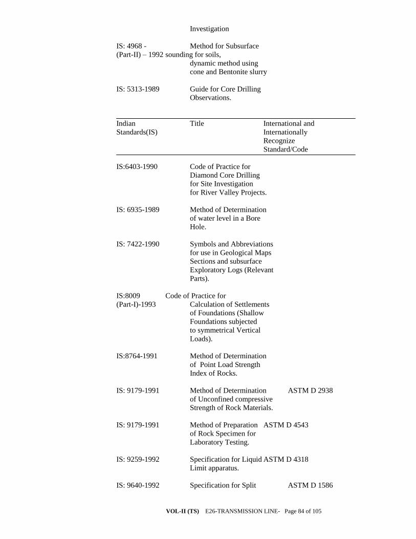
VOL-II (TS) E26-TRANSMISSION LINE- Page 84 of 105
Investigation
IS: 4968 - Method for Subsurface
(Part-II) – 1992 sounding for soils,
dynamic method using
cone and Bentonite slurry
IS: 5313-1989 Guide for Core Drilling
Observations.
Indian Title International and
Standards(IS) Internationally
Recognize
Standard/Code
IS:6403-1990 Code of Practice for
Diamond Core Drilling
for Site Investigation
for River Valley Projects.
IS: 6935-1989 Method of Determination
of water level in a Bore
Hole.
IS: 7422-1990 Symbols and Abbreviations
for use in Geological Maps
Sections and subsurface
Exploratory Logs (Relevant
Parts).
IS:8009 Code of Practice for
(Part-I)-1993 Calculation of Settlements
of Foundations (Shallow
Foundations subjected
to symmetrical Vertical
Loads).
IS:8764-1991 Method of Determination
of Point Load Strength
Index of Rocks.
IS: 9179-1991 Method of Determination ASTM D 2938
of Unconfined compressive
Strength of Rock Materials.
IS: 9179-1991 Method of Preparation ASTM D 4543
of Rock Specimen for
Laboratory Testing.
IS: 9259-1992 Specification for Liquid ASTM D 4318
Limit apparatus.
IS: 9640-1992 Specification for Split ASTM D 1586

VOL-II (TS) E26-TRANSMISSION LINE- Page 85 of 105
Spoon Sampler
IS: 10050-1992 Method of Determination ASTM D 4644
of Slake Durability Index
of Rocks.
IS: 11315- Description of Discontinuities
(Part-II)-1991 in Rock Mass-Core Recovery
TESTS Tests as indicated in this specification and as may be requested by the
Owner, shall be conducted. There tests shall include but may not be
limited to the following :
a) Tests of undisturbed and disturbed samples
- Visual and engineering classification;
- Sleeve analysis and hydrometric analysis;
- Liquid, plastic and shrinkage limits;
- Specific gravity;
- Chemical analysis
- Swell pressure and free swell index determination
- Proctor compaction test.
b) Tests of undisturbed samples:
- Bulk density and moisture content;
- Relative density (for sand),
- Unconfined compression test;
- Box shear test (for sand);
- Tri-axial shear tests (depending on the type of soil and field conditions on
undisturbed or remoulded samples):
i) Unconsolidated untrained;
ii) Consolidated drained test;
- Consolidation.
c) Tests on rock samples
- Visual classification:
- Moisture content, porosity and density:
- Specific gravity;
- Hardness
- Stake durability;
- Unconfined compression test (both saturated and at in-situ water content;
- Point load strength index;
- Deformability test (both saturated and dry samples)