Embed Size (px)
Citation preview

TECHNICAL SPECIFICATIONS
FOR CONTINUOUS AMBIENT AIR
QUALITY MONITORING (CAAQM)
STATION
(REAL TIME)
Central Pollution Control Board East Arjun Nagar, Shahdara
Delhi - 110032.

Page 1 of 43
CONTENTS
S.No. Titles Page Nos.
1. CAAQM STATION – HOUSING/CONTAINER 7-10
1.1 Housing/Container for Continuous Ambient Air Quality Monitoring (CAAQM) Station including sampling system, internal fittings, instrument racks, electrical and gas line fittings, tools (electrical & mechanical), etc.
2. SPLIT AIR CONDITIONER (AC) 10-11
2.1 Split Air Conditioner (2 Ton Capacity )
2.2 Split Air Conditioner (1 Ton Capacity )
3. ONLINE UNINTERRUPTED POWER SUPPLY (UPS) 11-12
3.1 Online UPS 10 KVA, capacity (Three Phase I/P and Single Phase O/P, with 01 hours backup) (for Air Conditioner)
3.2. Online UPS 5 kVA, capacity (Single Phase I/P & Single phase O/P, with 02 hrs backup) (01 for Analysers & 01 for Server at Central Station)
4. CONTINOUS AMBIENT AIR QUALITY MONTORING ANALYSER/SYSTEM 13-15
4.1 General Specification for all Analysers
4.2 Sampling System
4.3 19” Rack
5. CONTINOUS AMBIENT AIR QUALITY ANALYSER (GAS) 16-19
5.1 Ambient SO2, Analyser
5.2 Ambient NO-NO2-NOx, Analyser
5.3 Ambient NH3, Analyser
5.4 Ambient CO, Analyser

Page 2 of 43
5.5 Ambient O3, Analyser
5.6 Ambient BTX, Analyser
6. CONTINOUS AMBIENT AIR QUALITY MONITORING ANALYSERS (PARTICULATES)
19-21
6.1 Continuous PM10 Monitoring Analyser (-RAY)
6.2 Continuous PM2.5 Monitoring Analyser (-RAY)
6.3 Continuous PM10 and PM2.5 Monitoring Analyser (TEOM)
7. MULTI CALIBRATOR 22
7.1 Multi Point Gas Calibration System
7.2 Meteorological, Flow and Electronics Calibration
8. METEOROLOGICAL SYSTEM 23-24
8.1 Meteorological System comprising of sensors for (A ) Wind Speed, (B) Wind Direction, (C) Ambient Temperature, (D) Relative Humidity, (E) Solar Radiation & (F) Rainfall, mounted on (G) Telescopic Crank-up Meteorological Tower
9. DATA ACQUISITION AND COMMUNICATION SYSTEM 25-30
9.1 Typical Architecture for Data Connectivity
9.2 Data acquisition and handling system at stations
9.3 Work Station Computer at stations (for AQI Preparation)
9.4 Manageable CISCO Switch (Rack Mountable)
Page 3 of 43
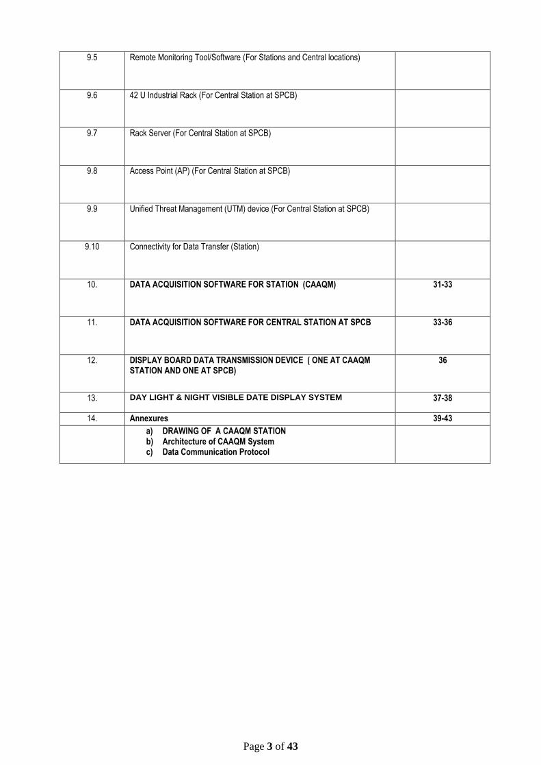
9.5 Remote Monitoring Tool/Software (For Stations and Central locations)
9.6 42 U Industrial Rack (For Central Station at SPCB)
9.7 Rack Server (For Central Station at SPCB)
9.8 Access Point (AP) (For Central Station at SPCB)
9.9 Unified Threat Management (UTM) device (For Central Station at SPCB)
9.10 Connectivity for Data Transfer (Station)
10. DATA ACQUISITION SOFTWARE FOR STATION (CAAQM) 31-33
11. DATA ACQUISITION SOFTWARE FOR CENTRAL STATION AT SPCB 33-36
12.
DISPLAY BOARD DATA TRANSMISSION DEVICE ( ONE AT CAAQM STATION AND ONE AT SPCB)
36
13. DAY LIGHT & NIGHT VISIBLE DATE DISPLAY SYSTEM
37-38
14. Annexures 39-43
a) DRAWING OF A CAAQM STATION b) Architecture of CAAQM System c) Data Communication Protocol

Page 4 of 43
SCHEDULE OF REQUIREMENTS
The equipment’s are intended for one Continuous Ambient Air Quality Monitoring (CAAQM) Station. The system should be completely functional. Any balance of material not specified but required for the purpose must be supplied by the vendors.
Brief Description Qty. in Nos.
CAAQM STATION – HOUSING/CONTAINER
Housing/Container for Continuous Ambient Air Quality Monitoring (CAAQM) Station including sampling system, internal fittings, instrument racks, electrical and gas line fittings, tools (electrical & mechanical), etc.
1 Unit
SPLIT AIR CONDITIONER (AC)
Split Air Conditioner (2 Ton Capacity ) 2 Unit
Split Air Conditioner (1 Ton Capacity ) 1 Unit
ONLINE UNINTERRUPTED POWER SUPPLY (UPS)
Online UPS 10 KVA, capacity (Three Phase I/P and Single Phase O/P, with 01 hrs backup) (for Air Conditioner)
1 Unit
Online UPS 5 kVA, capacity (Single Phase I/P & Single phase O/P, with 02 hrs backup) (01 for Analysers & 01 for Server at Central Station)
2 Unit
CONTINOUS AMBIENT AIR QUALITY MONTORING ANALYSER/SYSTEM
General Specification for all Analysers
Sampling System 1 Unit
19” Rack 3 Unit
CONTINOUS AMBIENT AIR QUALITY MONITORING ANALYSERS (GAS)
Ambient SO2, Analyser 1 Unit
Ambient NO-NO2-NOx, Analyser 1 Unit
Ambient NH3, Analyser 1 Unit
Ambient CO, Analyser 1 Unit

Page 5 of 43
Brief Description Qty. in Nos.
Ambient O3, Analyser 1 Unit
Ambient BTX, Analyser 1 Unit
CONTINOUS AMBIENT AIR QUALITY MONITORING ANALYSERS (PARTICULATES)
(1A. & 1B. OR 2.)
1A. Continuous PM10 Monitoring Analyser(-RAY) 1 Unit
1B. Continuous PM2.5 Monitoring Analyser(-RAY) 1 Unit
2. Continuous PM10 and PM2.5 Monitoring Analyser (TEOM) 1 Unit
MULTI CALIBRATOR
Multi Point Gas Calibration System 1 Unit
Meteorological, Flow and Electronics Calibration
1 Unit
METEOROLOGICAL SYSTEM
Meteorological System comprising of sensors for (A ) Wind Speed, (B) Wind Direction, (C) Ambient Temperature, (D) Relative Humidity, (E) Solar Radiation & (F) Rainfall, mounted on (G) Telescopic Crank-up Meteorological Tower
1 Unit
DATA ACQUISITION AND COMMUNICATION SYSTEM
Data acquisition and handling system at stations 1 Unit
Work Station Computer at stations (for AQI Preparation) 1 Unit
Manageable CISCO Switch (Rack Mountable) 1 Unit
Remote Monitoring Tool/Software (For Stations and Central locations) 1 Unit

Page 6 of 43
Brief Description Qty. in Nos.
42 U Industrial Rack (For Central Station at SPCB) 1 Unit
Rack Server (For Central Station at SPCB) 1 Unit
Access Point (AP) (For Central Station at SPCB) 1 Unit
Unified Threat Management (UTM) device (For Central Station at SPCB) 1 Unit
Connectivity for Data Transfer (Station) 1 Unit
DATA ACQUISITION SOFTWARE FOR STATION (CAAQM) 1 Unit
DATA ACQUISITION SOFTWARE FOR CENTRAL STATION AT SPCB 1 Unit
DISPLAY BOARD DATA TRANSMISSION DEVICE ( ONE AT CAAQM STATION AND ONE AT SPCB)
2 Unit
DAY LIGHT AND NIGHT VISIBLE DATA DISPLAY SYSTEM (ONE AT CAAQM STATION AND ONE AT SPCB)
2 Unit

Page 7 of 43
TECHNICAL SPECIFICATIONS
1. CAAQM STATION –HOUSING/ CONTAINER
1.1 Housing/Container: It is designed for housing the ambient air quality
monitoring instruments to protect them from dust and heat. Temperature and
Humidity sensors shall be installed in the housing for checking the humidity and
temperature inside the station. Three Nos. 19” racks shall be installed inside the
station so that the analyzers are easily accessible from front & back for calibration
and maintenance.
1.1.1 Dimensions: Inside length: 4200 mm
Inside width: 3500 mm
Inside height: 2500 mm
(As per the Drawing given)
1.1.2 Frame: All the material used for the construction of the floor, frame, roof frame
etc, the 4 corner posts and 8 integrated, reinforced container corners should be of
metal. The exterior panel of the container shall be made of pre-coated MS Sheet
of approved colour shade. All other steel parts should be hot dipped galvanized
having minimum rate of galvanization of 275 gram per square meter (IS277). All
joints of like metal such as steel-to-steel or aluminum-to-aluminum shall be
protected against corrosion by liberal application of joining compound. All joints of
dissimilar metals such as steel to aluminum shall be protected against corrosion
due to galvanic action by liberal application of dielectric compound as well as
jointing compound on both mating surfaces. For lifting / fixing the container,
International Standard eyebolts should be provided at the corners.
1.1.3 Paneling: The outer paneling will be of 1.2 mm of Pre-coated MS sheet to
withstand external impacts and abrasions. Outer side of the MS Sheet i.e. exposed
face of the sheet, shall be permanently colour coated with silicon modified
polyester coating of dry film thickness (DFT) 20 micron (min.) of approved colour
shade over primer. Inner face of the sheet shall be provided with suitable pre-
coating of minimum 7 micron off-white colour. The inner paneling will be of PVC
coated 2 mm thick aluminum sheet, fixed over an inlay of 4 mm marine plywood.
100 mm thick polyurethane insulation will be used between the outer and inner
walls (Pre-coated MS sheet and Marine plywood) as insulating material. Z spacers
if required shall be made out of at least 2 mm thick galvanized steel sheet of
grade 275 as per IS:277
1.1.4 Floor: The floor will be laid in frame of 600 x 600 mm centre to centre with 50
x50 x 6 mm MS angle. The floor surface will be of 19 mm marine plywood covered
with robust quality Vinyl flooring, 2 mm thick of approved colour. The floor should
be of acid and alkaline resistant, waterproof, easily cleanable / washable. Bottom
plate of thickness 2 mm hot dipped galvanised MS Plate shall be provided.
1.1.5 Outer Door: One door of size 2000 x 900 mm will be provided at the front side
(L = 4200 mm) of the station with isolated 3 – point locking & door handle flush
fitted.
1.1.6 Electric Power Supply Box: Three - phase (3 Ø) electrical wiring will be laid
in ducts. Copper wiring of appropriate gauge will be used. The terminal board
should be mounted in a central power distribution box. Over voltage protection for
each phase shall be provided along with the lightning arrestor. 2 numbers
Emergency cut off switch & Thermostat switch (max 350C) for power
disconnection, 6 free sockets and 3 fluorescent lamps for lighting will be provided.
Page 8 of 43
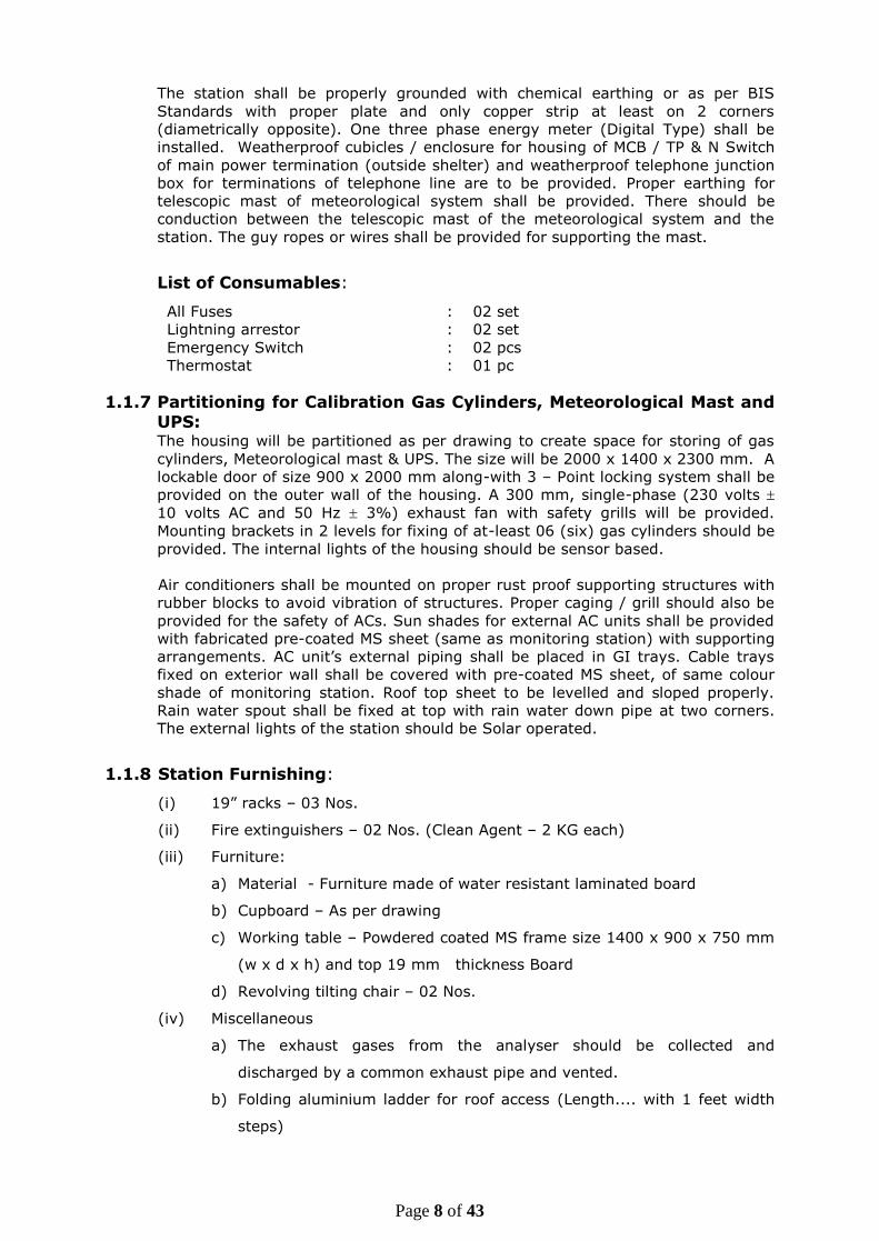
The station shall be properly grounded with chemical earthing or as per BIS
Standards with proper plate and only copper strip at least on 2 corners
(diametrically opposite). One three phase energy meter (Digital Type) shall be
installed. Weatherproof cubicles / enclosure for housing of MCB / TP & N Switch
of main power termination (outside shelter) and weatherproof telephone junction
box for terminations of telephone line are to be provided. Proper earthing for
telescopic mast of meteorological system shall be provided. There should be
conduction between the telescopic mast of the meteorological system and the
station. The guy ropes or wires shall be provided for supporting the mast.
List of Consumables:
All Fuses : 02 set
Lightning arrestor : 02 set
Emergency Switch : 02 pcs
Thermostat : 01 pc
1.1.7 Partitioning for Calibration Gas Cylinders, Meteorological Mast and
UPS: The housing will be partitioned as per drawing to create space for storing of gas
cylinders, Meteorological mast & UPS. The size will be 2000 x 1400 x 2300 mm. A
lockable door of size 900 x 2000 mm along-with 3 – Point locking system shall be
provided on the outer wall of the housing. A 300 mm, single-phase (230 volts
10 volts AC and 50 Hz 3%) exhaust fan with safety grills will be provided.
Mounting brackets in 2 levels for fixing of at-least 06 (six) gas cylinders should be
provided. The internal lights of the housing should be sensor based.
Air conditioners shall be mounted on proper rust proof supporting structures with
rubber blocks to avoid vibration of structures. Proper caging / grill should also be
provided for the safety of ACs. Sun shades for external AC units shall be provided
with fabricated pre-coated MS sheet (same as monitoring station) with supporting
arrangements. AC unit’s external piping shall be placed in GI trays. Cable trays
fixed on exterior wall shall be covered with pre-coated MS sheet, of same colour
shade of monitoring station. Roof top sheet to be levelled and sloped properly.
Rain water spout shall be fixed at top with rain water down pipe at two corners.
The external lights of the station should be Solar operated.
1.1.8 Station Furnishing:
(i) 19” racks – 03 Nos.
(ii) Fire extinguishers – 02 Nos. (Clean Agent – 2 KG each)
(iii) Furniture:
a) Material - Furniture made of water resistant laminated board
b) Cupboard – As per drawing
c) Working table – Powdered coated MS frame size 1400 x 900 x 750 mm
(w x d x h) and top 19 mm thickness Board
d) Revolving tilting chair – 02 Nos.
(iv) Miscellaneous
a) The exhaust gases from the analyser should be collected and
discharged by a common exhaust pipe and vented.
b) Folding aluminium ladder for roof access (Length.... with 1 feet width
steps)

Page 9 of 43
c) Sensor for measuring the inside temperature of the station and Display
d) Hygrometer for measurement of Humidity inside the station and
Display
e) Mounting bracket for the ladder
f) No smoking stickers
g) Vacuum cleaner with minimum 100 watt power
h) Tool Kit having following tools:
1. One screw driver set
2. One Digital multi-meter (Philips, Micro or equivalent make)
3. One box spanner set
4. One D spanner set
5. One watch maker set
6. One Hammer set
7. One precision screw driver set
8. One pliers set
9. One Tong tester
10. One Soldering Iron with stand
i) One Emergency LED Cluster light
j) Sign boards along-with logo of Central Pollution Control Board, Delhi /
State Pollution Control Board, to be embedded with size 1500 x 900
mm on the front of the container and on the two side of the container,
The name of the Station i.e. Continuous Ambient Air Quality
MONITORING Station, (Location) both in English and Hindi or local
language to be inscribed. The Signs boards to be mounted on the
station with proper spacers.
1.1.9 Container Foundation (RCC)
L X W 6000 x 6000 mm
Height 300 mm from ground
Pillars: Nine concrete pillars of 300 mm above the ground level and below the
ground level with 200 x 200 mm beam and between pillar bricks to be used
for filling the space(concrete ratio of 1:2:4). Outer wall of the foundation
to be plastered with 1:4, Cement: Sand ratio and same has to be painted
with weather proof coat.
Top of the platform: RCC 150 mm with concrete ratio of 1:1:2 and to plaster and
painted with weather proof paint.

Page 10 of 43
Staircase: RCC Steps to approach the main door of the container and the UPS /
Gas room door in the side to be provided and each step should not be
more than 150 mm
1.1.10 Security Cabin
A 4 feet x 4 feet wooden / Paneled security cabin with chair and small folding table
for security guard with covered overhead selves to be provided separately with the
station container.
2. SPLIT AIR CONDITIONER
2.1 SPLIT AIR CONDITIONER (2.0 TON CAPACITY)
2.1.1 Type & Capacity: 2 Nos. split type, 2 ton capacity AC, roof mounted of 5 star
rating with an automatic timer. Separate Automatic Voltage stabilizer will be
provided with each unit.
2.1.2 The indoor units should be running alternately at an interval of four hours with
timer control and the temperature inside the station should be maintained at 250
C inside during all the time including peak summer months.
a. Cooling Capacity:7000 W
b. Star Rating: BEE 5 star
c. Indoor Noise Level: 40db
d. Control Type: Remote
e. Compressor: Rotary
f. Refrigerant: Eco Friendly
g. Feature: filter clean Indicator, defrosting Sensor
h. Power supply: 230 volts 10volts AC and 50 Hz 3%
i. Standard Warranty
j. Remote: LCD Wireless.
2.2 SPLIT AIR CONDITIONER (1.0 TON CAPACITY)
2.2.1 Type & Capacity: 1 Nos. split type, 1 ton capacity AC, roof mounted of 5 star
rating with an automatic timer. Separate Automatic Voltage stabilizer will be
provided with each unit.
2.2.2 The indoor units should be running alternately at an interval of four hours with
timer control and the temperature inside the station should be maintained at 250
C inside during peak summer months.
a) Cooling Capacity:3400 W
Page 11 of 43
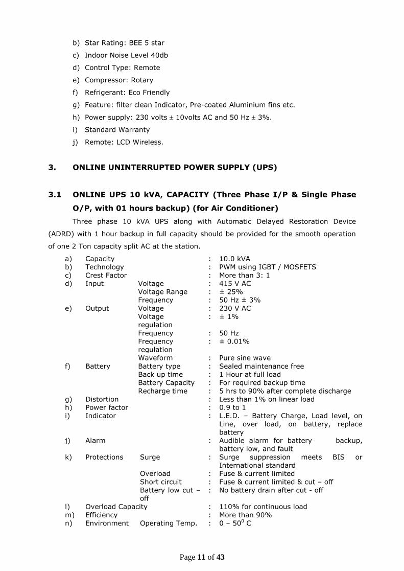
b) Star Rating: BEE 5 star
c) Indoor Noise Level 40db
d) Control Type: Remote
e) Compressor: Rotary
f) Refrigerant: Eco Friendly
g) Feature: filter clean Indicator, Pre-coated Aluminium fins etc.
h) Power supply: 230 volts 10volts AC and 50 Hz 3%.
i) Standard Warranty
j) Remote: LCD Wireless.
3. ONLINE UNINTERRUPTED POWER SUPPLY (UPS)
3.1 ONLINE UPS 10 kVA, CAPACITY (Three Phase I/P & Single Phase
O/P, with 01 hours backup) (for Air Conditioner)
Three phase 10 kVA UPS along with Automatic Delayed Restoration Device
(ADRD) with 1 hour backup in full capacity should be provided for the smooth operation
of one 2 Ton capacity split AC at the station.
a) Capacity : 10.0 kVA
b) Technology : PWM using IGBT / MOSFETS
c) Crest Factor : More than 3: 1
d) Input Voltage : 415 V AC
Voltage Range : ± 25%
Frequency : 50 Hz ± 3%
e) Output Voltage : 230 V AC
Voltage
regulation
: ± 1%
Frequency : 50 Hz
Frequency
regulation
: ± 0.01%
Waveform : Pure sine wave
f) Battery Battery type : Sealed maintenance free
Back up time : 1 Hour at full load
Battery Capacity : For required backup time
Recharge time : 5 hrs to 90% after complete discharge
g) Distortion : Less than 1% on linear load
h) Power factor : 0.9 to 1
i) Indicator : L.E.D. – Battery Charge, Load level, on
Line, over load, on battery, replace
battery
j) Alarm : Audible alarm for battery backup,
battery low, and fault
k) Protections Surge : Surge suppression meets BIS or
International standard
Overload : Fuse & current limited
Short circuit : Fuse & current limited & cut – off
Battery low cut –
off
: No battery drain after cut - off
l) Overload Capacity : 110% for continuous load
m) Efficiency : More than 90%
n) Environment Operating Temp. : 0 – 500 C

Page 12 of 43
Operating Hum. : 10% to 95% (Non condensing)
Audible Noise : Less than 45 db (at 1 meter)
3.2 ONLINE UPS 5 KVA, CAPACITY (Single Phase I/P & Single phase
O/P, with 02 hours backup) ( 01 for Analysers & 01 for Server at
Central Station) :-
Single phase 5 kVA UPS along with Automatic Delayed Restoration Device (ADRD) with 2
hours backup in full capacity should be provided for the smooth operation of Analyzers
and peripherals at the station:
3.2.1 Capacity : 5.0 kVA
3.2.2 Technology : PWM using IGBT / MOSFETS
3.2.3 Crest Factor : More than 3: 1
3.2.4 Input Voltage : 230 V AC
Voltage Range : ± 25%
Frequency : 50 Hz ± 3%
3.2.5 Output Voltage : 230 V AC
Voltage regulation : ± 1%
Frequency : 50 Hz
Frequency regulation : ± 0.01%
Waveform : Pure sine wave
3.2.6 Battery Battery type : Sealed maintenance free
Back up time : 2 Hours at full load
Battery Capacity : For required backup time
Recharge time : 5 hrs to 90% after complete
discharge
3.2.7 Distortion : Less than 1% on linear load
3.2.8 Power factor : 0.9 to 1
3.2.9 Indicator : L.E.D. – Battery Charge, Load
level, on Line, over load, on
battery, replace battery
3.2.10 Alarm : Audible alarm for battery
backup, battery low and fault
3.2.11 Protections Surge : Surge suppression meets BIS or
International standard
Overload : Fuse & current limited
Short circuit : Fuse & current limited &
cut – off
Battery low cut – off : No battery drain after cut - off
3.2.12 Overload Capacity : 110% for continuous load
3.2.13 Efficiency : More than 90%
3.2.14 Environment Operating Temp. : 0 – 500 C
Operating Humidity : 10% to 95% (Non condensing)
Audible Noise : Less than 45 db (at 1 meter)

Page 13 of 43
4. CONTINUOUS AMBIENT AIR QUALITY MONITORING ANALYSERS
for SO2, NO-NO2-NOx, NH3, CO, O3 and BTX
4.1 (General Specifications for all Analysers)
4.1.1 The analyzers should be 19” rack mounting model with facilities for fixing the
analyzers from front side.
4.1.2 The front panel should have ON / OFF Switch.
4.1.3 The display of the entire important status signal viz. Sample flow, temperature,
concentration, range selection, manual / auto mode, zero / span mode and all error
messages should be on front panel.
4.1.4 The analyzers should operate at operating voltage 230 volts 10 volts AC and 50 Hz
3% frequency. The power supply input to be protected against spikes from and to
the analyzer by an LC filter. The power connection cable should be CEE type
complete with 15 Amperes plug adaptable to Indian mains socket.
4.1.5 The analyzers must function properly in Indian conditions without any defect
between 0 – 50o C ambient temperature, 10 – 95% relative humidity and in high
ambient dust levels. The data capture rate should not be less than 90% of
operational time.
4.1.6 The Manufacturer shall provide comprehensive hands-on training for operational &
preventive maintenance for one week in the respective State for three persons per
station.
4.1.7 The analyzers should complete with calibration system. The calibration system should
be delivered along-with respective span gas cylinder and permeation tubes. The span
gas concentration should be within 60 – 90% of first measuring range. The analyzer
must have zero point internal calibration system and in agreement with minimum
detection limit of each analyzer. The calibration procedures are to be integrated into
the software system for automatic calibration & remote calibration.
PERMEATION TUBE
4.1.8 The analyzer of SO2, NO-NO2-NOx, NH3 & BTX should have the permeation bench with
NIST certified permeation tube for the span check in the analyzer. The date of
Calibration Certificate of Permeation Tube should not be older than 30 days on the
date of commissioning of the respective analyzer. Thus, it is desirable that the
consignment of permeation tubes may be dispatched separately.
CALIBRATION GAS CYLINDER
4.1.9 The supplier has to supply the calibration gas cylinder (highly polished aluminium 10
liters water capacity), along with SS Regulator, traceable to NIST for each
components (SO2, NO, CO, NH3, Benzene & Toluene) along with SS regulator for the
multipoint calibration. The synthetic air and N2 cylinder (99.99% purity with
certificate) should be in Carbon Steel cylinder of 47 Liters water capacity along with
SS Regulator.
4.1.10 The analyzers shall be supplied with all ancillaries necessary for operation with pump
(preferably in built) and any other items such as charcoal scrubber, Teflon air sample
intake filter, drier, Teflon tubing suitable for connection to air sampling manifold. All
such items are to be itemized. Dust filter in all the analyzers should be provided
before solenoid valve to protect frequent chocking of solenoid valve.
4.1.11 The connector systems for out-going signal for recording and the computer terminal
should be on back panel with screw type connecting pins.
4.1.12 All ambient gas analyzers shall be approved by the USEPA / TUV / MCERTS / EN.
However, in case of BTX and Ammonia Analyzer specifications as given will be
considered. Method of measurement used shall also comply with the stipulation on
National Ambient Air Quality Standards (NAAQS) 2009 (Details of Methods of
Measurement is available at MoEF and CPCB websites). All analyzers shall be micro –
processor controlled with automatic calibration using an external dilution calibrator
and calibration standards. All analyzers should be fully integrated in the rack
cabinet, fully calibrated & tested before supply and ready for start – up at the

Page 14 of 43
respective sites. Analyzer must exhibit performance equal to or better than values
specified in the Calibration & test certificate provided with each analyzer.
4.1.13 The manufacturer shall specify the cross sensitivity of measurement for all the
analyzers.
4.1.14 Each set of analyzers shall be supplied with two copies of elaborate operation
manuals comprising details as below:
Parts (I) should comprise installation, operational and troubleshooting details;
Parts (II) should have details about preventive, routine and corrective maintenance;
Parts (III) should comprise details of all electrical, electronic and pneumatic circuit
diagrams, details of each spare parts, catalogue No. etc. and details of each
electronic card / PCB’s; and
Parts (IV) Schematic diagram for possible repair & maintenance.
Parts (V) Standard Operating Procedure (SOP) for each analyzer.
Parts (VI) List of equipments and other accessories along with contact details of
supplier.
4.1.15 Digital Output:
a) Multi drop RS 232 port shared between gas Analyzers, Dust Analyzer (PM2.5& PM10),
Meteorological Sensors and computer for data, status and control. Communication
should have a USB port, TCP/IP Ethernet connection
4.1.16 Quality Control and Standard
Data shall be collected and validated according to US EPA standards, using the
methodologies included in 40 Code of Federal Regulations. All analyzers shall
have current US EPA reference or equivalent method designation and shall be of
the latest design.
The supplier shall submit a Standard Operating Procedure for the air quality
monitoring stations to the Buyer at the time of bid submission. This Standard
Operating Procedure shall be approved by the Buyer prior to award. The
Standard Operating Procedure shall contain the following:
i. Operating procedures for all analyzers and meteorological sensors
ii. Calibration procedures
iii. Calibration schedule
iv. Maintenance procedures
v. Maintenance schedule
vi. Data validation procedures
vii. Quality Assurance procedures
viii. Sample quality assurance documentation
ix. Sample Air Quality Report
The calibration procedures for analyzers shall conform to US EPA methodologies
and shall include daily calibration checks, by weekly precision checks and
linearity checks every six weeks. All analyzers shall undergo full calibration in
every three months. Data obtained from these calibration checks and copies of
associated Quality Assurance and calibration documentation, shall be submitted
to the Buyer along with the Air Quality Data.
Air Quality Data shall be submitted to the Buyer on Real Time basis through
automated system and on a monthly basis in the form of an Air Quality Report.
This report shall include tabular and graphic information on gas and dust
Page 15 of 43
concentrations as well as meteorological data for each site. The data shall be
reported in the form of 15 minute averages and shall also include daily, weekly
and monthly averages, minimum, maximum, standard deviations, total data
captured and percent data capture. It should also have stat validation
mechanism and delayed data check mechanism. The Air Quality Report shall also
include wind roses where wind speed and direction are measured.
Upon 24 hour notice from the Buyer, once per year, the supplier shall agree to
submit to an audit of calibrations, conducted, using pre-approved US EPA
methodologies, by a third party. The results of these audits shall be made
immediately available to both the supplier and Buyer.
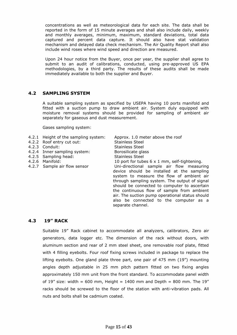
4.2 SAMPLING SYSTEM
A suitable sampling system as specified by USEPA having 10 ports manifold and
fitted with a suction pump to draw ambient air. System duly equipped with
moisture removal systems should be provided for sampling of ambient air
separately for gaseous and dust measurement.
Gases sampling system:
4.2.1 Height of the sampling system: Approx. 1.0 meter above the roof
4.2.2 Roof entry cut out: Stainless Steel
4.2.3 Conduit: Stainless Steel
4.2.4 Inner sampling system: Borosilicate glass
4.2.5 Sampling head: Stainless Steel
4.2.6 Manifold: 10 port for tubes 6 x 1 mm, self-tightening.
4.2.7 Sample air flow sensor Uni-directional sample air flow measuring
device should be installed at the sampling
system to measure the flow of ambient air
through sampling system. The output of signal
should be connected to computer to ascertain
the continuous flow of sample from ambient
air. The suction pump operational status should
also be connected to the computer as a
separate channel.
4.3 19” RACK
Suitable 19” Rack cabinet to accommodate all analyzers, calibrators, Zero air
generators, data logger etc. The dimension of the rack without doors, with
aluminum section and rear of 2 mm steel sheet, one removable roof plate, fitted
with 4 filling eyebolts. Four roof fixing screws included in package to replace the
lifting eyebolts. One gland plate three part, one pair of 475 mm (19”) mounting
angles depth adjustable in 25 mm pitch pattern fitted on two fixing angles
approximately 150 mm unit from the front standard. To accommodate panel width
of 19” size: width = 600 mm, Height = 1400 mm and Depth = 800 mm. The 19”
racks should be screwed to the floor of the station with anti-vibration pads. All
nuts and bolts shall be cadmium coated.

Page 16 of 43
5. AMBIENT AIR QUALITY MONITORING ANALYSERS (GAS)
5.1 AMBIENT SULPHUR DIOXIDE (SO2) ANALYSER
01. Principle : Pulsed UV Fluorescence
02. Measurement : SO2in Ambient Air
03. Display : Digital
04. Ranges : Auto ranging 0 - 200 ppb
05. Lower Detectable Limit : 1 ppb
06. Noise Level : 0.5 ppb
07. Zero Drift : < 1 ppb/24 Hrs. with automatic zero
compensation
08. Span Drift : <1 ppb in 24 hrs.
09. Linearity : ± 1% of full scale
11. Response Time : 120 sec or less
12. Span check facility : Built in permeation bench
13. Calibration : Please see Multi-calibration section
(Sl. No. 7) and also calibration section in
General Specifications(4.1.7 to 4.1.9)
14. Analog Output : 0 – 1 V, 0 – 10 V, 2 – 20 mA / 4 – 20 mA
15. Digital Output : Multiple drop RS 232, USB port /TCP/IP
,Ethernet
5.2 AMBIENT OXIDES OF NITROGEN (NO-NO2-NOx) ANALYSER
5.3 AMBIENT AMMONIA ANALYSER (NH3)
01. Principle Chemiluminiscence (NH3 conversion to NO by
oxidation. NO2 also converted to NO. The
difference obtained by measuring NO in output
of two sample stream as equal to NH3)
02. Measurement NH3in Ambient Air
03. Display Digital
04. Ranges Auto ranging 0-1000 ppb
05. Lower Detectable Limit 1 ppb
01. Principle : Chemiluminiscence
02. Measurement : NO-NO2- NOx in Ambient Air
03. Display : Digital
04. Ranges : Auto ranging 0-2000 ppb
05. Lower Detectable Limit : 1 ppb
06. Noise Level : 0.5 ppb
07. Zero Drift : < 1 ppb/24 Hrs.
08. Span Drift : < 2% in 15 days of full scale
09. Linearity : 1% of full scale
10. Response Time : 120 sec or less
12. Span Check : Built in permeation bench
13. Calibration : Please see Multi-calibration section
(Sl. No. 7) and also calibration section in
General Specifications (4.1.7 to 4.1.9).
14. Analog Output : 0 – 1 V, 0 – 10 V, 2 – 20 mA / 4 – 20 mA
15. Digital Output : Multi drop RS 232 port, USB port /TCP/IP
,Ethernet

Page 17 of 43
06. Noise Level 0.2% of reading
07. Zero Drift <5 ppb /24 Hrs.
08. Span Drift < 2% in 15 days of full scale
09. NH3/NO converter Quartz at approx. 10000 C
10. Linearity 1% of full scale
11. Response time 180 second
12. Rise / fall Time (95% of
the final value)
< 30 Sec
13. Span Check facility Built in permeation bench
14. Calibration Please see Multi-calibration section (Sl. No. 7)
and also calibration section in General
Specifications (4.1.7 to 4.1.9).
15. Analog Output 0 – 1 V, 0 – 10 V, 2 – 20 mA /4 – 20 mA and
Digital output
16. Digital Output Multi drop RS 232 port, USB port /TCP/IP
,Ethernet
5.4 AMBIENT CARBON MONOXIDE (CO) ANALYSER
01. Principle : Non Dispersive Infra-Red (NDIR) with Gas
Filter Correlation
02. Measurement : CO in Ambient Air
03. Display : Digital
04. Ranges : Auto ranging 0 - 100 ppm.
05. Lower Detectable Limit : 0.1 ppm
06. Noise Level : 0.05 ppm with time constant
30 seconds
07. Zero Drift : < 0.2 ppm/7 days
08. Span Drift : < 1% full scale in 24 hrs.
09. Linearity : Continuous + 1%
10. Response Time : 30 seconds or less
11. Calibration : Please see Multi-calibration section (Sl. No. 7)
and also calibration section in General
Specifications (4.1.7 to 4.1.9).
12. Analog Output : 0 – 1 V, 0 – 10 V, 2 – 20 mA / 4 – 20 mA
13. Digital Output : Multiple drop RS 232port, USB port /TCP/IP
,Ethernet
5.5 AMBIENT OZONE (O3) ANALYSER
01. Principle : UV Photometric / Chemiluminiscence
02. Measurement : O3 in Ambient Air
03. Display : Digital
04. Range : Auto ranging 0 - 500 ppb
05. Lower Detectable Limit : 1.0 ppb
06. Noise level : 0.5 ppb
07. Zero Drift : < ½% per month
08. Span Drift : < 1% per month
09. Linearity : Continuous + 1%
10. Response Time : 30 seconds or less
11. Calibration : With built in Zero and span generator and also
see Multi-calibration section (Sl. No. 7)
12. Analog Output : 0 – 1 V, 0 – 10 V, 2 – 20 mA / 4 – 20 mA
13. Digital Output : Multiple drop RS 232 port, USB port /TCP/IP
,Ethernet

Page 18 of 43
5.6 AMBIENT BTX ANALYSER 5.6.1 GENERAL
A complete analyzer system comprising of sampling pump, transfer line, analyzer,
detector, calibrator, computer hardware and software for instrument control, data
storage, display, acquisition, processing and for selective determination of volatile
compounds in ambient air optimized for Benzene, Toluene, Ethyl Benzene and o,
m, p –Xylenes. Continuous unattended measurement system of individual BTX
should work without external cryogenic cooling. System should have protocol
compatible to communicate & transfer data to DAS. Raw data storage capacity
without erase minimum for three month or more. The system should be delivered
with all necessary spares, consumables, tubing etc. for making it functional.
5.6.2 TECHNICAL SPECIFICATIONS
A single stage membrane Pump collect ambient sample automatically an inbuilt
adsorption trap. Subsequent, the sample will be dissolved and injected on wide
bore capillary gas chromatographic separation. Sample volume controlled by
thermal mass flow controller (dust protected). Sample flow range may be 20 -100
ml/min or more (adjustable). Sample volume should be between 400 ml – one
liter or more of ambient air over a 10-15 min sampling cycle. All sample transfer
tubing should be in stainless steel and flow & pressure sensor to be preferred with
digital display.
5.6.3 DETECTOR
Photo Ionization Detector (PID) or other equivalent detector as per
EPA/EU/TUV/MCERT approved specifications, which do not require hydrogen or
other gas to operate it. The system should have auto-clean & auto calibration
facilities. PID Lamp eV should be 10.6 eV. PID sensitivity sensor should be
available to check sensitivity.
5.6.4 MINIMUM SPECIFICATIONS
Principal : Based on gas Chromatographic separation and
Photo Ionization Detector (PID)
Measurement : Benzene, Toluene, Ethyl-benzene, m.p-Xylene and
0-Xylene.
Display : Digital
Range : 0 - 100 ppb
(0.32 – 325g/m3)
Lower detectable
limit
:
0.2 ppb (0.65g/m3) for 15 min cycle for Benzene
Temperature Range : 5 - 35oC or more
Repeatability : Retention Time : <0.1% RSD
Concentration: <1.0% RSD
Typical Cycle Time : Total Cycle Time should not exceed 15min i.e.
Sample Collection Time -15 min approx.
Analytical Time- 15 min approx.
Sample Volume : 1 liter for 15 min cycle.
Desorption tube : Carbotrap
Pre concentration : Carbopack
Span Check Built in permeation bench with NIST certified
Benzene& Toluene permeation tube.
Calibration : The Analyzer should be capable to calibrate through

Page 19 of 43
Multi Calibration System also. Please see Multi-
calibration section (Sl. No. 7) And also calibration
section in General Specifications (4.1.7 & 4.1.9).
Analog Output : 0 – 1 V, 0 – 10 V, 2 – 20 mA / 4 – 20 mA
Digital Output : Multi drop RS 232 port, USB port /TCP/IP ,Ethernet
6. CONTINUOUS AMBIENT AIR QUALITY MONITORING ANALYSERS
(PARTICULATES)
6.1 CONTINUOUS PM10 MONITORING ANALYSER (-RAY
ATTENUATION)
Based on the principle of -ray attenuation, particulate sampled through the
instrument and collected on fiberglass filter tape. Before and after sampling, -
ray radiation is measured by scintillation / G.M. counter. An internal
microprocessor handles all sequences and automatically calculates the
concentration of PM10.
01. Principle : -ray attenuation
02. Particle Size Cut Off : 0 - 10 Microns
03. Measuring Range : User selectable (0 – 500, 0 – 1000 & 0 -2000
g/m3) with auto ranging feature
04. Resolution : 1% of the measurement range
05. Lower Detectable Limit : 2 g/m3
06. Detector : Plastic Scintillator / GM Counter
07. Air Flow Rate : At least 1.5 m3 / hr
08. Filter Material : Glass Fiber Filter
09. Display : LED / LCD
10. Sampling Head : Dynamic heated sampling head for measurement of
PM10, with adjustable temperature 20 – 70 0C
11. Calibration : Reference membrane facility should be provided for
calibration of analyzer.
12. Compatibility : Analyzer should be compatible with protocols of
DAS system to be used in station.
13. Analog Output : 0 – 1 V, 0 – 10 V, 2 – 20 mA / 4 – 20 mA
14. Digital Output : Multi drop RS 232 port USB port /TCP/IP /Ethernet
15. Roll Length : Minimum 20 meters
14. Measurement interval : 1min. to 60 minute (user selectable) Generally
measurement shall be done at a frequency of 15
minutes.
6.2 CONTINUOUS PM2.5 MONITORING ANALYSER (-RAY ATTENUATION)
Based on the principle of -ray attenuation, particulate sampled through the
instrument and collected on fiberglass filter tape. Before and after, sampling -
ray radiation is measured by scintillation / G.M. counter. An internal
microprocessor handles all sequences and automatically calculates the
concentration of PM2.5.
01. Principle : -ray attenuation
02. Particle Size Cut Off : 0 – 2.5 Microns
03. Measuring Range : User selectable (0 – 500, 0 – 1000 & 0 -2000
g/m3) with auto ranging feature
04. Resolution : 1% of the measurement range
05. Minimum Detectable
Limit
: 2 g/m3

Page 20 of 43
06. Detector : Plastic Scintillator / GM Counter
07. Air Flow Rate : At least 1.5 m3 / hr.
08. Filter Material : Glass Fiber Filter
09. Display : LED / LCD
10. Sampling Head : Dynamic heated sampling head for measurement of
PM2.5 with adjustable temperature 20 – 70 0C
11. Calibration : Reference membrane facility should be provided for
multipoint calibration of analyzer.
12. Compatibility : Analyzer should be compatible with protocols of
DAS system to be used in station.
13. Roll Length : Minimum 20 meters
14. Analog Output : 0 – 1 V, 0 – 10 V, 2 – 20 mA / 4 – 20 mA
15. Digital Output : Multi drop RS 232 port ,USB port /TCP/IP ,Ethernet
16. Measurement Interval : 1min. to 60 minute (user selectable) Generally
measurement shall be done at a frequency of 15
minutes.
6.3 AMBIENT PARTICULATE ANALYSER (PM10 & PM 2.5) BASED ON THE
PRINCIPLE “TAPERED ELEMENT OSCILLATING MICROBALANCE” (TEOM) CONFORMING TO USEPA AUTOMATED FEDERAL
EQUIVALENT METHOD (FEM) DESIGNATION (EQPM-0609-182/EQPM-0822-207/EQPM-0822-208)
SPECIFICATIONS
TEOM 1405-DF Ambient Particulate Analyzer (PM 2.5 & PM10) = Dual TEOM
(FDMS)
Regulatory Designations
• Approval and Certificates: U.S. EPA approved PM2.5 equivalent Analyzer (EQPM-
0609-182), USEPA PM10-PM2.5 Equivalent Monitor (EQPM-0822-207), US EPA PM10
and equivalent monitor (EQPM-0822-208) and TUV-PM2.5 and PM10 equivalent
monitor.
Standard System Configuration
• Menu-driven software for user interaction via 1/4 VGA display with touch screen
• Connecting and Interface Cables, and Vacuum Pump
• Consumables for average three year’s operation (ambient)
• RPCOMM and ePort Software for Local or Remote Communication
Instrument Performance
• Measurement Range: 0 to 1,000,000 μg/m³ (1 g/m³)
• Resolution: 0.1 μg/m³
• Precision: ±2.0 μg/m³ (1-hour average), ±1.0 μg/m³ (24-hour avg.)
3 l/min, 1s, stable conditions
• +0.1 μg/m³ (24 hr average), accuracy for Mass Measurement: ±0.75%
Data Averaging and Output
• Real-time Mass Conc. Average: 1 hour rolling average updated every six minutes
• Long-Term Averaging: 1, 8, and 24 hr
• Data Output Rate: Selectable from 10 sec to 24 hour
Page 21 of 43
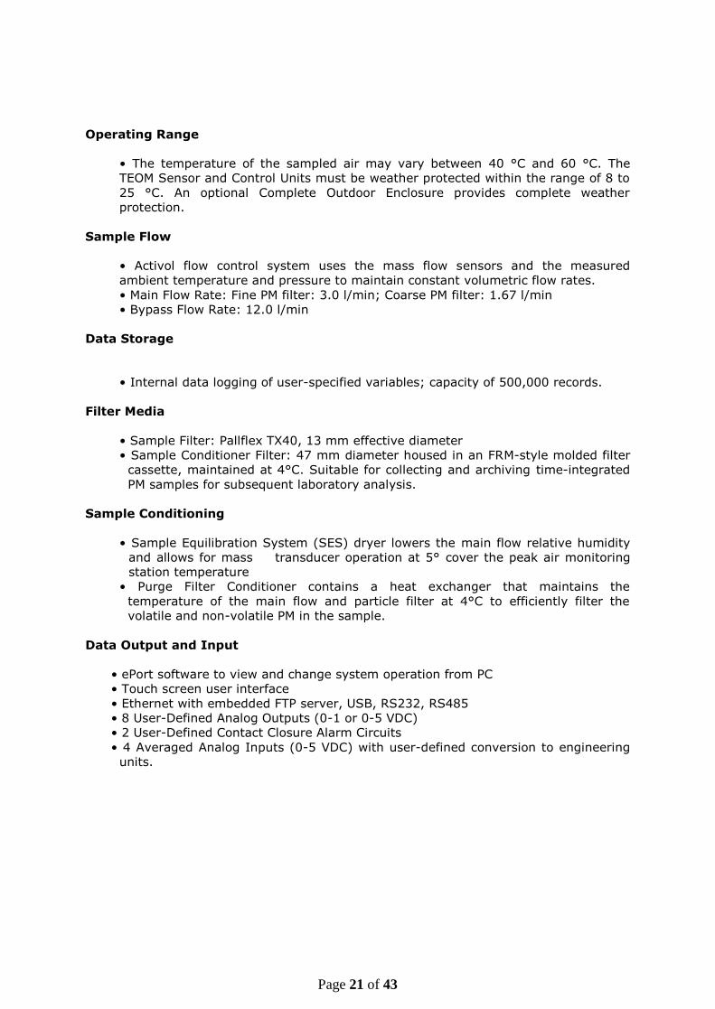
Operating Range
• The temperature of the sampled air may vary between 40 °C and 60 °C. The
TEOM Sensor and Control Units must be weather protected within the range of 8 to
25 °C. An optional Complete Outdoor Enclosure provides complete weather
protection.
Sample Flow
• Activol flow control system uses the mass flow sensors and the measured
ambient temperature and pressure to maintain constant volumetric flow rates.
• Main Flow Rate: Fine PM filter: 3.0 l/min; Coarse PM filter: 1.67 l/min
• Bypass Flow Rate: 12.0 l/min
Data Storage
• Internal data logging of user-specified variables; capacity of 500,000 records.
Filter Media
• Sample Filter: Pallflex TX40, 13 mm effective diameter
• Sample Conditioner Filter: 47 mm diameter housed in an FRM-style molded filter
cassette, maintained at 4°C. Suitable for collecting and archiving time-integrated
PM samples for subsequent laboratory analysis.
Sample Conditioning
• Sample Equilibration System (SES) dryer lowers the main flow relative humidity
and allows for mass transducer operation at 5° cover the peak air monitoring
station temperature
• Purge Filter Conditioner contains a heat exchanger that maintains the
temperature of the main flow and particle filter at 4°C to efficiently filter the
volatile and non-volatile PM in the sample.
Data Output and Input
• ePort software to view and change system operation from PC
• Touch screen user interface
• Ethernet with embedded FTP server, USB, RS232, RS485
• 8 User-Defined Analog Outputs (0-1 or 0-5 VDC)
• 2 User-Defined Contact Closure Alarm Circuits
• 4 Averaged Analog Inputs (0-5 VDC) with user-defined conversion to engineering
units.

Page 22 of 43
7. MULTICALIBRATOR
Calibration system should provide for the calibration of the ambient air quality
monitoring analysers (Gas).
7.1 MULTI POINT GAS CALIBRATION SYSTEM:
1. The Gas Calibration System should be capable to do the following:
(i) Multipoint calibration using automatic dilution system for the calibration
of SO2, NO, CO, NH3 and BTX analyser.
(ii) Auto calibration (user selectable).
(iii) Generate zero air of 99.9% purity (High Performance Zero Air
Generator to be provided).
(iv) Gas Phase Titration (GPT) with O3 generator having 100% converter
efficiency for conversion of NO2 to NO.
(v) Calibration using permeation tubes for which at least two chambers
based Permeation system has to be provided.
(vi) The Permeation System should be capable to accept permeation tubes
up to 6 cm in length and 2cm in diameter with user selectable
temperature setting of 40 OC and 50 OC.
2. System should be 19” rack mountable.
3. System should be DAS compatible for remote calibration from Central Server.
4. The system should also have facility for multipoint calibration of Ozone
analyzer.
7.2 METEOROLOGICAL, FLOW AND ELECTRONICS CALIBRATION
The supplier should provide calibration devices or calibration check devices for all
the meteorological parameters namely temperature, wind speed, wind direction,
relative humidity, solar radiation, rain fall as per the specifications of the
manufacturers.

Page 23 of 43
8. METEOROLOGICAL SYSTEM
8.1 The meteorological instrumentation should be interfaced directly with the Data
Acquisition System after passing through a lightning protection isolation box. A crank
- up telescopic 10 meters tower should be erected for mounting of meteorological
sensors. The relative humidity and solar radiation sensors should be mounted on the
tower. The specifications are as follows:
(A) WIND SPEED
Range (Operation) : 0 – 60 m/s or better
Sustainability : Up to 75 m/sec
Accuracy : ± 0.5 m/sec or better
Resolution : 0.1 m/sec
Sensor Type : Ultrasonic
Threshold : 0.5 m/sec or less
Response time : 10 sec or better
(B) WIND DIRECTION
Range : 0 – 359 degree
Accuracy : ± 3 degree or better
Resolution : 1 degree
Sensor type : Ultrasonic
Threshold : 0.5 m/sec or less
Response time : 10 sec or better
(C) AMBIENT TEMPERATURE
Range : -10 o C to 60 o C
Accuracy : ± 0.2 o C or better (with radiation shield)
Response : 10 seconds in still air
Resolution : 0.1 °C
Sensor type : Resistance type
Response time : 10 sec or better
(D) RELATIVE HUMIDITY
Range : 0 to 100% RH
Accuracy : ± 3.0 % or better
Resolution : 1%
Sensor type : Capacitive / Solid State
Response Time : 10 sec or better
(E) SOLAR RADIATION
Range : 0 to 1500 W/m2 or better
Accuracy : ± 5.0 % or better
Resolution : 5W/m2
Sensor type : Silicon Photo diode
(F) RAINFALL
Range : 0.2 mm to 100 mm /hr
Accuracy : ± 5% or better
Resolution : 0.2 mm
Sensor type : Tipping bucket rain gauge or any other
suitable sensor
Response Time : 10 sec or better
Page 24 of 43
(G) TELESCOPIC CRANK – UP METEOROLOGICAL TOWER
The wind speed, wind direction, temperature, relative humidity and solar radiation
sensors are to be mounted on the Meteorological Tower. The tower is to be a free
standing four section telescopic tower provided with a hand crank to raise and lower
the instruments mounted on the tower. Specifications are as follows:
Extended Height : 10 meters
Retracted Height : 2 metres
Wind load Limit : 0.7896 sq. m. (8.5 sq. ft) at 50 mph
Number of Sections : 4
Construction material : Galvanised steel or aluminium
Note: Humidity and temperature sensors are to be supplied with weather and thermal
radiation shield made of anodized aluminium and sensor should be supplied with all
necessary cables, connector and mounting arrangements as required.

Page 25 of 43
9. DATA ACQUISITION AND COMMUNICATION SYSTEM
9.1 Typical Architecture for Data Connectivity

Page 26 of 43
9.2 Data Acquisition and Handling System at Station
Type I: System comprises of data logger having DAS and station computer.
Or
Type 2: System comprises of station computer with DAS facilities.
Data logger/DAS with 8 analog, 24 digital inputs. Ability to log channels at different
intervals and should have capability of averaging and displaying real time data and
averaged data over a period of 1 min, 15 min, ½ hr, 1 hr, 4 hrs, 8 hrs, 24 hrs, 1
month and year. Communication between data logger and station computer should
be using standard USB/RS 232 Connector. The data logger should have internal
battery with charger.
The data logger/DAS should support LAN and Internal GSM modem/ Wifi for data
transfer to central server. Station computer for data logging will be in addition to
workstation computer required for calculating AQI, and will be of same or better
specifications that of work station computer.
9.3 WORKSTATION COMPUTER FOR AQI
This has to be installed at CAAQM station for the preparation of AQI along with
the station computer.
Sr.No Specifications
1 CPU Intel® Core i7 (3 GHz, 8 MB cache, 4 cores) or higher
2 Memory 8 GB DDR-III, 1066MHz,
3 Ethernet
ports
Dual Gigabit Ethernet ports with autosensing bidder can
provide 2nd NIC card on PCI , Autosensing is to cater to
100/1000 Mbps speeds automatically and not a boot ROM
4 PCI Slots Provision for additional cards, 2PCI, PCIex1, PCIx16 ( Total 4
slots)
5 Optical
Drive DVD R/W 16X Drive, Internal
6 HDD’s 3.5” 1TB, SATA drives
7 Power
Supply Standard suitable power supply
8 Key board Optical Keyboard same as OEM
9 Mouse Standard Optical Mouse same as OEM
10 I/O ports 4*USB,
11 Monitor 17” Wide LCD TFT Color Monitor
12 Wireless
adapter USB Wireless adapter x 1 no.
13 OS support Open source Ubuntu latest release
14 Warranty Warranty is comprehensive on site including spares for 3 / 3 /
3 years
15 Type Tower type Black in color preferably or as per the fitting in
station rack
9.4 MANAGEABLE CISCO SWITCH (RACK MOUNTABLE) Ethernet switch with LAN and WAN ports.
24 port managed fast/ gigabit Ethernet Cisco Switch with LAN and WAN ports of
latest series for installation at respective SPCBs.

Page 27 of 43
9.5 REMOTE MONITORING TOOL/SOFTWARE
Remote management software and its licenses for the entire project duration for
station computer and central location at SPCB.
9.6 42 U INDUSTRIAL RACK
This is to be installed at respective SPCBs Central station.
Sr.
No Specifications QTY / site
1 19" Industrial Rack, 42U , Color Black Consisting of:- 1
2
Steel Enclosure, 9 Folded profile of dimensions 800 mm width * 1000
mm Depth * 42 U height, supporting 1000 Kgs load. Bottom cover
with knock out holes for cable entry to be provided. Three pairs of
horizontal support shall be fitted on both right and left sides.
1
3
Foldable Front & Rear Door to its half size while opening, shall be of
100% perforated. Provision for mounting fans on Rear door with
concealed AC wiring.
2
4 Fan 230V, 90 CFM to be mounted on Rear Door. 4
5 AC Main Channel vertical two nos., 12x 5/15 Amps Sock RT-AQMP
Make: Anchor with 32 Amps MCB make : Northwest or better 2
6 Horizontal Cable Manager 20
7 Vertical Cable Manager 10
8 Copper based Electrical Grounding / Earthing Strip. Provision for
Fifteen (15) points. 1 Set
9 Each set of: a) Castor with Brake -- 2 Nos. 1 Set
b) Adjustable screw legs --4 Nos. OR
c) Base frame – 1 No.
10 Light provision activation in the rack up on opening of the front/rear
door. 1
11 H/W Packet of 20 SRT-AQMP. 2
If anything else is required to setup the system, vendor need to have provision
at the time of quoting.
9.7 RACK SERVER
This is to be installed at respective SPCBs Central station
Sr.No Specifications
1. CPU Single CPU, Intel Xeon Quad Core E51620V3 3.50
GHz or higher, 10MB Cache per socket or higher. The
Mother Board should support Dual Sockets.
2. Memory 32
(32 GB Support for each CPU)
DDR-4, 1333/1600/1866/2133MHz, upgradable to
128 GB
3. Mother Board Intel motherboard having compatibility to
configuration desired
4. HDD 3*500GB SAS or better

Page 28 of 43
5. Ethernet Port 2 *Dual port Gigabit NIC Cards with autosensing and
on copper (total 4 ports). All four ports supporting
iSCSI protocol to connect to iSCSI based SAN storage
6. PCI Slots Provision for 2 *PCI express 2 * PCIe X2 or more
slots to accommodate additional FC/Gigabit Cards
Graphics Adaptors
7. Optical Drive DVD R/W 16X Drive or better, External USB based
8. Form Factor 2U rack model with rail kit or better
9. Key board Standard Optical wireless Keyboard
10. Mouse Standard Optical Wireless Mouse
11. I/O ports 2 *USB ports, front & 2USB port Back,
1 VGA Port, 1 external SAS, 1* Serial
12. Monitor 22” Wide LCD TFT Colour monitor
13. RAID Controller RAID 5 minimum
14. Wireless adapter USB Wireless adapter x 2 nos.
15. Antivirus Standard Antivirus (McAfee / Norton / Trend Micro)
for duration of 3 years
16. Redundant Power
Supply & Fans
Redundant Power Supply 1+1, Redundant Fans
17. Warranty Warranty is comprehensive 24x7 on site including
spares for 3 / 3 / 3 years with 4 hours support
9.8 ACCESS POINT (AP)
This is required along with server at respective SPCBs central station.
S. No
Specification
1 Features
1 Ethernet, 1 mini PC Ie, USB, Additional
memory,
Gigabit, High power, Dual chain, Outdoor case
2 CPU Atheros AR9342 600MHz network processor
3 Memory 64MB DDR on board memory
4 Ethernet One Gigabit port with Auto-MDI/X
5 Wireless Built in 2GHz 802.11b/g/n, 2x RP-SMA connectors
6 Connector
type RP-SMA Female (outside thread)
7 Extras
Beeper, signal and status LEDs, SIM slot (requires
3g miniPCIe card), voltage and temperature
sensors
Page 29 of 43
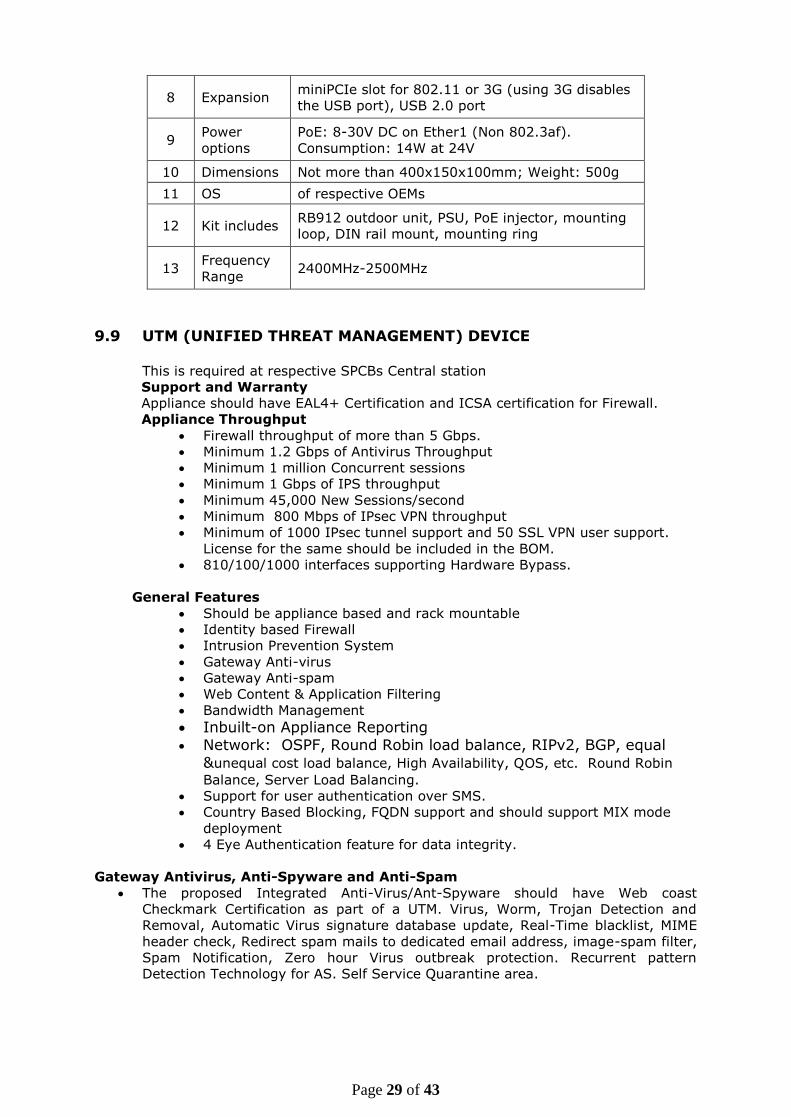
8 Expansion miniPCIe slot for 802.11 or 3G (using 3G disables
the USB port), USB 2.0 port
9 Power
options
PoE: 8-30V DC on Ether1 (Non 802.3af).
Consumption: 14W at 24V
10 Dimensions Not more than 400x150x100mm; Weight: 500g
11 OS of respective OEMs
12 Kit includes RB912 outdoor unit, PSU, PoE injector, mounting
loop, DIN rail mount, mounting ring
13 Frequency
Range 2400MHz-2500MHz
9.9 UTM (UNIFIED THREAT MANAGEMENT) DEVICE This is required at respective SPCBs Central station
Support and Warranty
Appliance should have EAL4+ Certification and ICSA certification for Firewall.
Appliance Throughput
Firewall throughput of more than 5 Gbps.
Minimum 1.2 Gbps of Antivirus Throughput
Minimum 1 million Concurrent sessions
Minimum 1 Gbps of IPS throughput
Minimum 45,000 New Sessions/second
Minimum 800 Mbps of IPsec VPN throughput
Minimum of 1000 IPsec tunnel support and 50 SSL VPN user support.
License for the same should be included in the BOM.
810/100/1000 interfaces supporting Hardware Bypass.
General Features
Should be appliance based and rack mountable
Identity based Firewall
Intrusion Prevention System
Gateway Anti-virus
Gateway Anti-spam
Web Content & Application Filtering
Bandwidth Management
Inbuilt-on Appliance Reporting Network: OSPF, Round Robin load balance, RIPv2, BGP, equal
&unequal cost load balance, High Availability, QOS, etc. Round Robin
Balance, Server Load Balancing.
Support for user authentication over SMS.
Country Based Blocking, FQDN support and should support MIX mode
deployment
4 Eye Authentication feature for data integrity.
Gateway Antivirus, Anti-Spyware and Anti-Spam
The proposed Integrated Anti-Virus/Ant-Spyware should have Web coast
Checkmark Certification as part of a UTM. Virus, Worm, Trojan Detection and
Removal, Automatic Virus signature database update, Real-Time blacklist, MIME
header check, Redirect spam mails to dedicated email address, image-spam filter,
Spam Notification, Zero hour Virus outbreak protection. Recurrent pattern
Detection Technology for AS. Self Service Quarantine area.
Page 30 of 43
Web and Application Filtering:
The proposed Content Filtering should have at least one Certification as part of a
UTM viz. Web coast Checkmark. URL, Keyword, File type block, Block Java
applets, cookies, ActiveX, Block malware, phishing, pharming URL, block P2P
application, anonymous proxies, Customized block on group basis. System should
have Minimum of 70+ categories with more than 100 million URLS supported with
more than 5000 application support.
Security Features
Intrusion Prevention System (IPS): The proposed IPS should have
Certification as part of a UTM viz. Web coast Checkmark. For different attacks like
Mail Attack, FTP Attack, HTTP Attack, DNS Attack, ICPM Attack, TCP/IP Attack,
DOS and DDOS Attack, Tel Net Attack. Signatures: Default (more than 2000+),
Custom , IPS Policies: Multiple, Custom, User-based policy creation, Automatic
real-time updates from CR Protect networks, Protocol Anomaly Detection
VPN:
IPsec, L2TP, PPTP and SSL as a part of Basic Appliance, VPN redundancy, Hub and
Spoke support, 3DES, DES, AES, MD5,SHA1 Hash algorithms, IPsec NAT
Transversal, VPNC Certified.
Load Balance:
For Automated Failover/Failback, Multi-WAN failover, WRR based Load Balancing.
High availability: Active-Active. QOS, OSPF, RIPv2, BGP, Policy routing based on
Application and User support Round Robin Load Balancing.
Bandwidth Management:
Application and user identity based bandwidth management, Multi WAN bandwidth
reporting, Guaranteed and Burstable bandwidth policy. Bandwidth for User,
Group, Firewall Rule, URL and Applications.
Monitoring and Reporting System:
Should Include reports for Centralized management, Monitoring & Logging,
Command line interface. Monitoring Gateways, Monitoring suspicious activity
and alerts, Graphical real-time and historical monitoring, email notification of
reports, viruses and attacks reports. IPS, Web filter, Antivirus, Anti-spam system
reports. IP and User basis report, >40+ Compliance reports and >1000+ drilled
down reports on the appliance with 250+ GB of storage.
License for UTM (Unified Threat Management)
Three Years for Gate Way Antivirus, spyware, Anti-Spam, content and application
filtering. IPS, reporting and support License period will be counted after activation
9.10 CONNECTIVITY FOR DATA TRANSFER
A) LEASED LINE CIRCUIT
1Mbps capacity leased line connectivity with 99% uptime service level
agreement (SLA) to be provided by the firm at each station location. The
leased line may be provided on copper or optical fiber or through RF
depending upon the location.
B) BROADBAND
1Mbps capacity broadband connectivity from other than one already providing
leased line connectivity shall be provided by the firm at each station.
C) GSM /Hotspot Connectivity
Internet connectivity will have to be provided by the firm for the entire project
duration at LED location either using GSM or Hotspot connectivity

Page 31 of 43
10. DATA ACQUISITION SOFTWARE FOR STATION (CAAQM) The software captures data from all channels in the system and stores in the
station Computer.
(i) Data Acquisition a) Frequency of data acquisition
i) User selectable 1,5,30,60,120 second averaging duration online digitally.
b) Channel size
i) 32 Channels or more supported
ii) Expandable to 64 channels, if required in future
c) Data input
Either Analog (0-1 volt/0-10 volt/2-20mA/4-20mA)
or Digital to configure with the PC.
d) User configurable channels, stations and equipment with communication
parameters.
e) Analyzer data channel should comprise of Name, Units, Communication
Address, Validity Range, Operation and Error Status.
f) Provision to incorporate conversion factors such as PPB to µg/m3 etc.
g) Software should be equipped to configure the analyzers with it, irrespective of
company make and communication protocol of the analyzer and the output
mode i.e. Analog or Digital (RS 232) of the instrument.
h) The output should be provided in user defined units.
(ii) Data Collection
a) Average data over user selectable time (1,5,30,60 seconds time interval)
period.
b) Operational status, Error status, calibration status and calibration values
observed from the analyzer should be captured and should be made available
along with the data with a frequency of maximum five minutes.
c) System should collect of the diagnostics of the instrument comprising actual
diagnostics parameters and their values at least once in every five minute to
check the state of the health analyzer.
d) Calibration parameters
i) Provision to entering zero calibration, span calibration values of gas
cylinder/permeation to devices
ii) Provision for collecting zero calibration, span calibration values(pre
calibration & post calibration) in to the database for further analysis.
iii) Provisions to collect electronic system pre calibration & post calibration to
ascertain the percentage deviation/ correction apply during each
calibration.
(iii) Data Storage a) Data along-with diagnostic, calibration, alarms should be stored at station
computer at a defined path.
b) Interval of data dumping will be same as defined in the data collection.
c) System should be capable to keep every second acquired data from 32
channels for a period of minimum five years.
d) Current data should be stored as per ISO-7168-1:1999I format and should be
available in folder named as c:\Data\ at an interval of 15 minutes. As an
example c:\data\01.05.2015.xml. the file will be appending without double
data entry and as per ISO format.
e) Data should also be stored for last two years in E:\data\Year\Month\day i.e.
e:\data\2015\05\01.05.2015.xml ….
f) If data encryption is done, then decryption procedure should be made
available in soft file format to check the data at station at any point of time.

Page 32 of 43
To convert data on continuous basis for exporting to AQI software, procedure
should be available without any licensing. AQI calculating Software will be
provided by CPCB/SPCB.
(iv) Data Display (Statistical analysis of data) a) Main window for real time display of all measured parameters with status of all
analyzers/sensors.
b) In 4-in-4 graphs and4-in-1 graph formats
c) In tables of 4-in-1 format
d) Real time multi – graphs over user selectable time period i.e. 6.00 AM to 6.00
AM etc.
e) Display of graphic & tabular display of the current data.
f) Graphical form should comprise of 4-4 graphs, 4-1 graphs in user defined
format ( 1, 5, 10, 15, 30 min, 1hour, 4, 8, 24 hour, 30 days and yearly; user
definable time series)
g) Tabular form should comprise of 4 channel list in user defined format (1, 5,
10, 15, 30 min, 1hour, 4, 8, 24 hour, 30 days and yearly; user definable time
series)
h) Station instruments basic configuration etc. should be visible on screen
continuously.
i) Statistical analysis tools like regression analysis, co-relation analysis and other
analysis as per industry standards in the field of environment should be
available and if not the firm should develop these for CPCB within a time
frame of six months.
j) The system should have procedures for normal analysis tools like calculation
of data with respect to a threshold value, average, minimum, maximum,
calculation of violating value with respect defined values(National Air Quality
Standards) for defined period for the database etc.
k) Data analysis of diagnostics parameters
l) Data analysis of Pre calibration and post calibration data (if facility not
available, should be developed within six months)
m) Data analysis of corrections applied of each calibration cycle (if facility not
available should be developed within six months)
(v) Data Backup a) There should be defined data backup procedure through which data can be
extracted from station computer in simple text format/excel/ ISO format(user
definable).
b) There should be defined restore procedure also to restore the data in case of
data loss.
c) A display screen should be available to update the user about data availability.
(vi) Data Validation automatic checks at station software. a) Zero level and span level checks if performed cyclically and defined results are
not obtained up to +/- 5%(user definable 0-10%) then system should alarm
the user of system failure and the recorded alarm should be transmitted to
central software.
b) After instruments perform the calibration the results obtained should be
recorded and should be transmitted to central computer.
c) There should be provision of two databases one is raw database and another
corrected database.
d) Validation of data through calibration database Pre calibration & post
calibration values collected.
(vii) Calibration of systems a. Calibration window for analyzer for the calibration from computer.
b. Remote Access to Calibration: Calibration exercise need to be done remotely.
All necessary arrangements for it should be made in the system.

Page 33 of 43
c. Calibration data file may be prepared separately and data should be excluded
from the database
d. Calibration database need to be formed, stored and transmitted to central
server.
e. Calibration cycles to be as per the models of the instruments.
f. Calibration records should store the calibration values displayed by instrument.
g. Diagnostics during calibration should also be recorded.
(viii) Location of station a) Fixed and Mobile Stations location to be recorded and North correction feature
should be available.
b) Latitude and longitude of stations be recorded
(ix) Data transfer to Central All data captured at station computer should be transferred to central software.
a) User selectable time frame for transmission of data to central server.
b) Diagnostics (actual diagnostics parameter values recorded each time in the
station), configurations(station channel configurations), alarms(generated
alarms) should be transmitted.
(x) Data transfer to Display Boards at Public site software should have provisions to connect data output including current
pollutants concentration, AQI, advertisement, etc. to the display boards (LEDs),
to be installed at public site. For the purpose Data display device has been
recommended in the document.
11. DATA ACQUISITION SOFTWARE AT THE CENTRAL STATION AT SPCB
Data communication system handles the data transmission of an ambient air quality
network and receives incoming messages / signals from remote stations. The central
software processes signals and data and displays it. Detailed requirement is as
below:
A (i) Software at Central Station a) Software should not have any restriction on number of locations and computers
either technologically or in terms of licensing.
b) Should display multiple stations on – line data (momentary values) in tabular
text and graphic format.
c) Data should be received by the central from all locations maximally within
5minutes duration or at user defined time intervals.
d) Data along-with diagnostics and calibration details should be transmitted at
central from all connected locations.
e) Should support dialup systems, broadband connectivity, wireless connectivity,
2G or 3G or any new technology which shall be in place during project time
should be compatible and if not, need to developed by the system provider up-
to project duration without additional charges.
f) Should have the remote control facilities for calibrations (Zero & Span) of
instruments and measuring range modifications.
g) Should have facility for displaying data communication error reports, image
management which should be recorded and should be available for display.
(ii) Data Display at Central Station
a) In 4-in-4 graphs, 4-in-1 graph and/or 16-in-1 graph formats
b) In terms of 4-in-1 table format
a) Real time multi – graphs over user selectable time period i.e. 6.00 AM to 6.00
AM etc.

Page 34 of 43
c) Display of graphic & tabular display of the current data like simple 3D line and
column chart, polar diagnostics and 3D perspective column chart.
d) Graphical form should comprise of 4-4 graphs, 4-1 graphs in user defined
format i.e. 1, 5, 10, 15, 30 min, 1hour, 4, 8, 24 hour, 30 days and yearly.
(user definable time series)
e) Tabular form should comprise of 4 channel list in user defined format i.e. 1, 5,
10, 15, 30 min, 1hour, 4, 8, 24 hour, 30 days and yearly. (user definable time
series)
f) Display of data using selectable name of different stations.
g) Generation of Wind Roses, Pollution Roses (minimum 12 directional)with user
defined time limits.
h) Calculate vector mean of wind direction.
i) Programmable downloading of data.
j) Comparison of data w.r.t. Standards in Graphical form and tabular form with
information of values exceeds the Standards.
k) Specific data zooming facility
l) Database correction procedure
m) Separate user ID and Password for correction of database so that all regional
level users if authorized can validate their regions data and the events be
recorded along-with ID and time.
n) Data validation trail recording.
(iii) Data Export
a) Data export in ISO 7168 format is required to be done automatically.
b) Possibility to export the data files in Excel, Text and other formats Tabular
form should be in user defined format i.e. 1, 5, 10, 15, 30 min, 1 hour, 4, 8,
24 hour, 30 days and yearly.
(iv) Data Import
a) In case of communication medium fails there should a mechanism to shift the
data into Pen drive (Physical medium for data collection) physically and a
procedure to import the same on central software.
(v) Printing
a) Possibility to connect different types of printers and auto printing facility for
all displays generated throughout the analysis of data at any point of time.
(vi) Delayed data checks at Central software at SPCB
a) After instruments perform the calibration the results obtained should be
recorded and should be transmitted to central computer and stored.
b) Zero level and span level checks if performed cyclically and defined results are
not obtained up to +/- 5% (user definable 0-10%) then system should
generate alarm to the user for system failure and the recorded alarm should
be transmitted to central software and stored. There should be provisions to
read these alarms in a database for corrective actions and for comparison of
data for acceptability or rejection.
c) Procedure to correct database through correct ISO 7168 file should be
generated at SPCB and it should be synced with Software under development
at Central Pollution Control Board (CPCB).

Page 35 of 43
(vii) Data display at SPCB Office / specific location through central
software
The software should have capability to display set of data including AQI etc. for all
the monitoring locations and cities (user selectable) in the State through slide
show mechanism.
(viii) Remote Procedures (if not available facility should be developed by the firm)
a) Central software should have capability to allow to connect any station
computer through remote.
b) Central software administrator should be able to go for remote calibration of
any of the systems.
c) Software should be capable to operate remote stations configurations.
d) Control panel window should be available for controlling each analyzer.
e) Alarm window for valid alarms of all analyzers and sensors.
f) It should have transparent data – connection to each analyzer from remote.
g) System should be capable to remotely configure all stations through remote
location using configuration file to maintain the uniformity. The configuration
command from central at SPCB location should be active.
(ix) Data Reports Generation
a) To prepare reports hourly, weekly, monthly, yearly in user defined interval
and formats.
b) Mean, Median, Percentile, Maximum, Standard deviation, Frequency analysis
and Maximum Frequency analysis.
c) Data Comparison
Software should be able to compare any of the four channels irrespective of
type of data in the system with respect to each other on a single time scale
user selectable.
d) Data Comparison on different time scale
Software should be able to compare data on the basis of different time scales
like one station (x) parameter (y) of one given date is compared with other
station (z) parameter (y) on any other date in a single graph.
e) Data reports, calibration reports and status reports with user time periods.
f) Historic multi – curves / graphs over user selectable time period.
g) Report generation over user selectable time period (instantaneous or
averaged over a period of 1, 15, 30 min, 1 hr, 4, 8, 12, 16 and 24 hrs etc.).
h) Diurnal variation, standard deviation, regression and other statistical
parameter reporting possibilities with various available mathematical
methods.
i) If required separate report generation procedures have to be developed for
which firm will be responsible for project duration. j) Data should be downloadable in Excel Sheet, CSV format through user
selection.
B. SECURITY
a. Software should be totally secured with protection against virus, malware etc.
b. Security device like firewall for VPN Tunneling should be installed.

Page 36 of 43
C. OTHER TECHNICAL CONDITIONS
1. Compatible Hardware required for data transmission through Data Display
Connection Device has to be installed.
2. Should support the latest formats of Windows 32 bit or 64 bit. Any new
patches developed or upgraded software during project duration should be
provided without additional cost.
3. Manual of complete system should be provided.
4. Firm should provide the hardware required for data acquisition along with all
the software’s required like OS, Networking software, Remote functionality
software and should maintain hardware and software for project duration.
12. DISPLAY BOARD DATA TRANSMISSION DEVICE
S. No.
Item Desc. Specifications
1. PROCESSOR Intel® Atom™ Processor E3815 (1.46 GHz Single
Core, 512 KB Cache, 5W TDP) or equivalent
Or 900 MHz or higher quad-core ARM Cortex-A7
2. Memory
Memory slots for MicroSD or full size SD card slot with
Memory support for at-least 8 GB
3. Ports
a. One HDMI
b. LAN Port for Ethernet Network Connection
c. Minimum of 3 USB Port with support for USB
2.0 or USB 3.0.
4. OS Support Linux, or Windows OS
5. Communication Options a. LAN Communication
b. Wifi Communication – Wifi Hotspot enabled/
GPRS Comm. Enabled
6. Power Supply 5 to 12 V DC through 220 V 50Hz AC Supply adapter
or USB driven.
7. Size Mechanical Chassis Size not to exceed 9’’ x 6’’x 6’’
with stand alone tower/box.
8. Operating Environment Operating Temperature 0° C to +50° C
Humidity upto 90%
9. Device Support 05 Years
10. Antivirus It should be secured
If Windows than life time antivirus should be there.
11. General Supplier will configure and deploy the communication
mechanism.
Complete manual of the device should be provided.
12 Accessories 01 Meter HDMI Cable
13. Internet To be provided by the vendor either through GSM SIM
or through Wifi Enabled Dongles.
14. Display Board should show Last data saved.
15. Display board should show Last updated time should be displayed
16 Software The vendor is responsible to provide software which
can download the data from Station computer, AQI,
Advertisements etc. store it and display on the
Display Board seamlessly.

Page 37 of 43
13. DAY LIGHT & NIGHT VISIBLE DATA DISPLAY SYSTEM
(A) LOCATION NEAR TO CAAQM STATION
1. Size of Display System ( H X W )
feet and Pixel
4 X 7 feet , 16 mm (+/- 0.5 mm ) pixel pitch, 3500
m2 minimum pixel Density
2. Visibility Range 50 Meters (Day time)
3. Brightness 8500 NIT or higher
4. Display of Colour Elements 1Red , 1Green, 1Blue pixel
5. Minimum Life span of the system LED Life 100000 Hours
6. Viewing angle Viewing angle of 140o Horizontal/77
o Vertical
7. Operating and non operating
Tempreture -15-55
0 C
8. No of Color 281 trillion Colors , 256 brightness level dimming
capability
9. Video processing 24 bit Video processing, 100 % Digital
10. Diode Density 1100m2 / 1000 ft2 ( minimum )
11. Scan rate and refresh frequency Scan Ratio 1:1 and with minimum 20000 hz refresh
frequency
12. LED internal and External Cabinet
type , Serviceability
Internal LED frame should be made of Aluminium
and External cabinet should be factory made
without pin holes , LED Display should be
serviceable from front and back
13. Color Temperature - Adjustable 4500 - 9000 K range
14. Input Power Requirement/
Consumption
120/240v, 50/60Hz , Power consumption 200 W (
maximum ) / m2
15. Type Discrete Diode
16. Display Mounting Structure based upon location. Uni Pole or hanging
17. General
The system should also have the facility to display
the enviromental picture through video
camera/vcr/cd player etc. for public awareness.
18. Power Cable Laying Depending upon location, cabeling is to be done by
the firm
19. Device at station to pick up data
and transmit it to LED
Display data connectivity device with GSM SIM
has to be installed near by LED board which will
pick up data from station computer through
Internet. LED to be placed away from through
Internet .LED to be placed away from the station
premises.
20. Certification CE, UL/ULC listed
21. IP Rating Display Module IP67, Cabinet IP 65

Page 38 of 43
(B) DAY LIGHT & NIGHT VISIBLE DATA DISPLAY SYSTEM
LOCATION FAR AWAY FROM CENTRAL STATION OF STATE
POLUTION CONTROL BOARD (SPCB)
1. Size of Display System ( H X W )
feet and Pixel
8 X 12 feet , 20 mm (+/- 0.6 mm ) pixel pitch,
2300 m2 minimum pixel Density
2. Visibility Range 50 Meters (Day time)
3. Brightness 8500 NIT or higher
4. Display of Colour Elements 1Red , 1Green, 1Blue pixel
5. Minimum Life span of the system LED Life 100000 Hours
6. Viewing angle Viewing angle of 140o Horizontal/59
o Vertical
7. Operating and non operating
Tempreture .-15-55
0 C
8. No of Color 281 trillion Colors , 256 brightness level dimming
capability
9. Video processing 24 bit Video processing, 100 % Digital
10. Diode Density 7000m2 ( minimum )
11. Scan rate and refresh frequency Scan Ratio 1:1 and with minimum 20000 hz refresh
frequency
12. LED internal and External Cabinet
type , Serviceability
Internal LED frame should be made of Aluminium
and External cabinet should be factory made
without pin holes , LED Display should be
serviceable from front and back
13. Color Temperature - Adjustable 4500 - 9000 K range
14. input Power Requirement/
Consumption
120/240v, 50/60Hz , Power consumption 180 W (
maximum ) / m2
15. Type Discrete Diode
16. Display Mounting Structure based upon location . Uni Pole or hanging
17. General
The system should also have the facility to display
the environmental picture through video
camera/vcr/cd player etc. for public awareness.
18. Power Cable Laying Depending upon location, cabeling is to be done by
the firm
19. Device at station to pick up data
and transmit it to LED
Display data connectivity device with GSM SIM
has to be installed near by LED board which will
pick up data from station computer through
Internet. LED to be placed away from through
Internet .LED to be placed away from the station
premises.
20. Certification CE, UL/ULC listed
21. IP Rating Display Module IP67, Cabinet IP 65

Page 39 of 43
14. ANNEXURE
(A) Drawing of a CAAQM Station
11
4200
3500
2100 200
0
1 . Roof Mounted Split AC 9. Working Table
2 . 19” Rack 10. Racks for spare parts
3 . Gas Bottles 11. Ambient Air Sampling System
4 . Mast for Meteorological Sensors 12. Dust Sampling System (PM
2.5&
PM10
)
5 . Battery Box for UPS 13. Sun Shed
6 . UPS Unit (5 and 10 kVA) 14. Air Conditioning unit
7 . Electric supply Box 15. UPS Room AC (1 Ton Capacity)
8 . Exhaust fan
1 1
14
14
2
7
2
2
11
13
5
6
6
5
9 10
8
15
3
12
4
All Dimensions are in mm
Drawing of Continuous Ambient Air Quality Monitoring Station

Page 40 of 43
(B) Architecture of CAAQM System
(C) Protocol for Data Transmission from CAAQM Stations
1. Data Format
Data file on real time basis having 15 minutes average values
in a prescribed format attached at Annexure-I should be
generated at the station for which Instrument Supplier is
responsible.
File should be updated after every 15 minutes. Data intervals like 00:15, 00:30, 00:45, 01:00 should be fixed at the
station.
Station file name should be exactly as the name of the
station to be displayed on the web portal. i.e. Sanathnagar,
NehruNagar. Here precaution is to be taken that no space
between words should be given or no special characters should
be used.
File should be recorded in a folder c: \data \sanathnagardata.txt
File should allow data appending sequentially.
Date of last file record appended in the file should be recorded and data afterwards be placed in the data file.
File appending should continue subject to max 97 lines. First
in First out mechanism shall be followed in keeping file size to 97
lines.

Page 41 of 43
Hence, in the specified folder c:\Data\ there will be a single
file which will keep appending as per format attached.
Duplicate entry of any data should not be made in the file.
System should have capability to create previous record data file
for which user will give the date. This is required to have lost
data makeup in the final database, if any.
2. Data Mapping
Protocol for each parameter is fixed as below:
1. 15 Minutes average value will be provided by the operator of the CAAQMS
2. Each SPCB will have the parameter as mentioned in
the table only. Not even a small gap or space is
provided other than the mentioned table is acceptable.
3. Standard Parameter Naming Protocol and Conversion factors Table
Parameters Name Parameter
Abbreviations
Unit Conversion factors
at 25°C
Rack Temperature Temp °C
Carbon Monoxide CO mg/m3 1ppm=1.145mg/m3
Sulphur Dioxide SO2 µg /m3 1ppb=2.62 µg/m3
Nitric Oxide NO µg /m3 1ppb=1.23 µg/m3
Nitrogen dioxide NO2 µg /m3 1ppb=1.88 µg/m3
Oxides of Nitrogen NOx Ppb --
Ozone Ozone µg /m3 1ppb=1.96 µg/m3
Particulate Matter less than PMio µg /rn3 --
10 Micron size
Wind Speed WS m/s --
Wind Direction WD Deg --
Ambient Temperature AT °C --
Relative Humidity RH % --
Barometric Pressure BP mmHg --
Solar Radiation SR W/mt2 --
Rain Fall RF Mm --
Vertical Wind Speed VWS Degree --
Particulate Matter less than
2.5 micron size
PM2.5 µg /m3 --
Benzene Benzene µg /m3 1ppb=3.19 µg/m3
Toluene Toluene µg /m3 1ppb=3.77 µg/m3
Xylene Xylene µg /m3 1ppb=4.34 µg/m3
Ethyl Benzene Eth-Benzene 1ppb=4.34 µg/m3
M+P_Xylene MP-Xylene 1ppb=4.34 µg/m3
Methane CH4 µg /m3 1ppb=0.65 µg/m3
Ammonia NH3 µg /m3 1ppb=0.70 µg/m3
Formaldehyde HCHO µg /m3 1ppb=1.23 µg/m3
Mercury Hg µg/m3 1ppb=8.20 µg/m3
Note: 1. Any other parameter can be added with the prior approval of IT Division ONLY.

Page 42 of 43
4. Internet Connectivity
Internet connectivity should be available on 24X7 basis for
data transmission with an uptime of 99.9%. For this purpose
every CAAQM station should have two kinds of connection:
i) Leased Line Circuit of at least 01 Mbps capacity
ii) Broad Band connectivity through telephone line. Both facilities should
be configured in ready to use condition. If possible auto failover should
be created.
Note: Connectivity through Data card is not acceptable except
in any special circumstances, where both of these types of
connectivity’s are not available. For such case CPCB IT Division
shall be consulted before taking a final decision.
5. Other Information:
1. Area Map showing station location
2. Latitude, Longitude and altitude of the station
3. Photo of station along with nearby areas
4. One page write-up about the station activities in the vicinity of station
including major pollution sources like nearby road, rail, restaurants,
generator sets, etc.
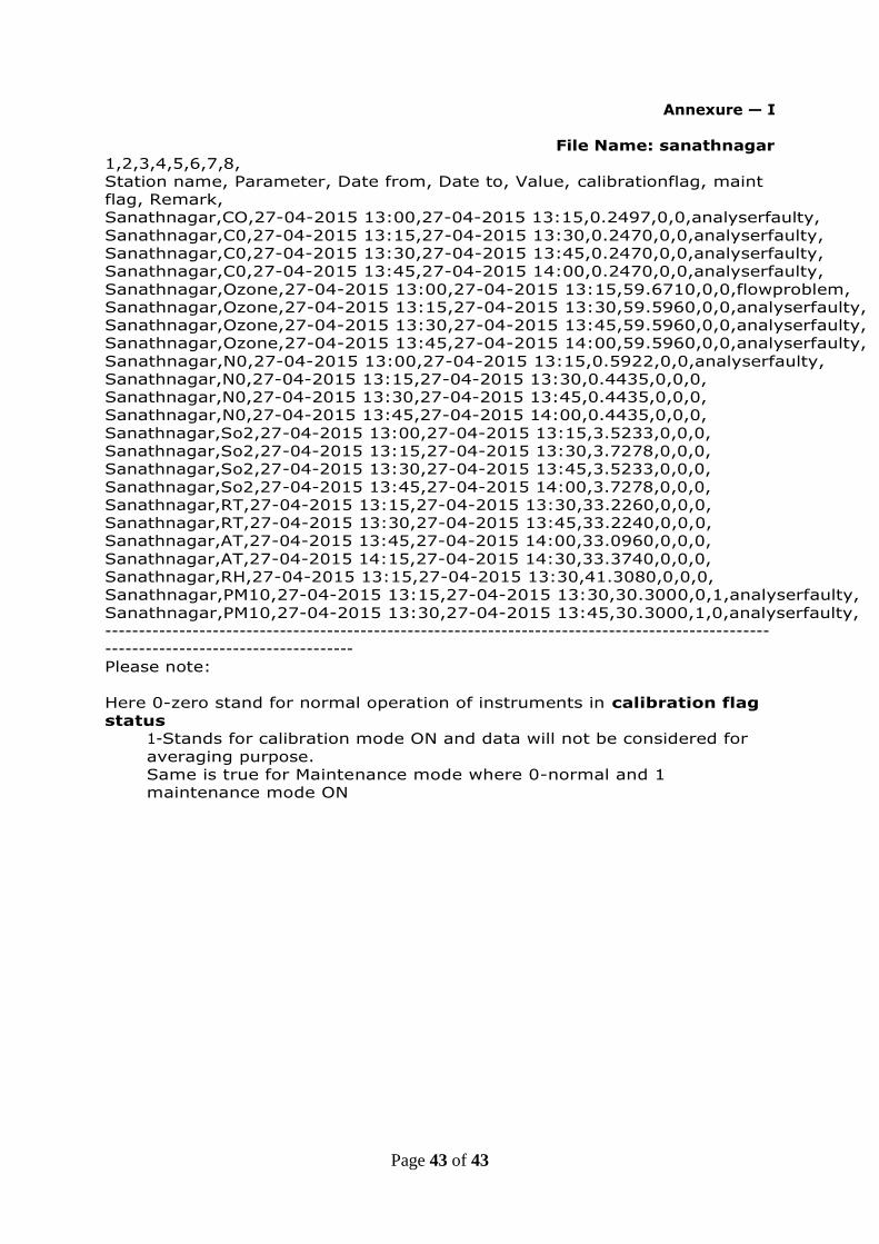
Page 43 of 43
Annexure — I
File Name: sanathnagar
1,2,3,4,5,6,7,8,
Station name, Parameter, Date from, Date to, Value, calibrationflag, maint
flag, Remark,
Sanathnagar,CO,27-04-2015 13:00,27-04-2015 13:15,0.2497,0,0,analyserfaulty,
Sanathnagar,C0,27-04-2015 13:15,27-04-2015 13:30,0.2470,0,0,analyserfaulty,
Sanathnagar,C0,27-04-2015 13:30,27-04-2015 13:45,0.2470,0,0,analyserfaulty,
Sanathnagar,C0,27-04-2015 13:45,27-04-2015 14:00,0.2470,0,0,analyserfaulty,
Sanathnagar,Ozone,27-04-2015 13:00,27-04-2015 13:15,59.6710,0,0,flowproblem,
Sanathnagar,Ozone,27-04-2015 13:15,27-04-2015 13:30,59.5960,0,0,analyserfaulty,
Sanathnagar,Ozone,27-04-2015 13:30,27-04-2015 13:45,59.5960,0,0,analyserfaulty,
Sanathnagar,Ozone,27-04-2015 13:45,27-04-2015 14:00,59.5960,0,0,analyserfaulty,
Sanathnagar,N0,27-04-2015 13:00,27-04-2015 13:15,0.5922,0,0,analyserfaulty,
Sanathnagar,N0,27-04-2015 13:15,27-04-2015 13:30,0.4435,0,0,0,
Sanathnagar,N0,27-04-2015 13:30,27-04-2015 13:45,0.4435,0,0,0,
Sanathnagar,N0,27-04-2015 13:45,27-04-2015 14:00,0.4435,0,0,0,
Sanathnagar,So2,27-04-2015 13:00,27-04-2015 13:15,3.5233,0,0,0,
Sanathnagar,So2,27-04-2015 13:15,27-04-2015 13:30,3.7278,0,0,0,
Sanathnagar,So2,27-04-2015 13:30,27-04-2015 13:45,3.5233,0,0,0,
Sanathnagar,So2,27-04-2015 13:45,27-04-2015 14:00,3.7278,0,0,0,
Sanathnagar,RT,27-04-2015 13:15,27-04-2015 13:30,33.2260,0,0,0,
Sanathnagar,RT,27-04-2015 13:30,27-04-2015 13:45,33.2240,0,0,0,
Sanathnagar,AT,27-04-2015 13:45,27-04-2015 14:00,33.0960,0,0,0,
Sanathnagar,AT,27-04-2015 14:15,27-04-2015 14:30,33.3740,0,0,0,
Sanathnagar,RH,27-04-2015 13:15,27-04-2015 13:30,41.3080,0,0,0,
Sanathnagar,PM10,27-04-2015 13:15,27-04-2015 13:30,30.3000,0,1,analyserfaulty,
Sanathnagar,PM10,27-04-2015 13:30,27-04-2015 13:45,30.3000,1,0,analyserfaulty,
---------------------------------------------------------------------------------------------------
-------------------------------------
Please note:
Here 0-zero stand for normal operation of instruments in calibration flag
status
1-Stands for calibration mode ON and data will not be considered for
averaging purpose.
Same is true for Maintenance mode where 0-normal and 1
maintenance mode ON