Embed Size (px)
Citation preview
PDF generated on 09 Aug 2016DISCLAIMER : UNCONTROLLED WHEN PRINTED – PLEASE CHECK THE STATUS OF THE DOCUMENT IN IDM
Technical Specifications (In-Cash Procurement)
Design Justification and Engineering Validation Work_Technical specifications
This document describes the technical needs for specialists in engineering of Diagnostics. Specifically the technical needs of the Diagnostics Division with particular reference to Design Justification and Engineering Validation Work. ITER is a major new device that is under construction at Cadarache, France. This device will study the potential of controlled nuclear fusion to provide energy for mankind. In order to study the behaviour of this device, a set of monitoring systems (referred ...
IDM UID
TLCXQKVERSION CREATED ON / VERSION / STATUS
08 Aug 2016 / 1.0 / Approved
EXTERNAL REFERENCE / VERSION
ITER_D_TLCXQK
Page 1 of 9
Table of Contents
1 PURPOSE............................................................................................................................22 SCOPE OF WORK.............................................................................................................23 DEFINITIONS ....................................................................................................................24 REFERENCES....................................................................................................................25 ESTIMATED DURATION................................................................................................26 WORK DESCRIPTION.....................................................................................................27 RESPONSIBILITIES .........................................................................................................3
7.1 Contractor’s Responsibilities .........................................................................................37.2 IO’s Responsibilities ......................................................................................................3
8 LIST OF DELIVERABLES AND DUE DATES .............................................................39 ACCEPTANCE CRITERIA..............................................................................................410 SPECIFIC REQUIREMENTS AND CONDITIONS......................................................411 WORK MONITORING / MEETING SCHEDULE .......................................................512 DELIVERY TIME BREAKDOWN..................................................................................513 QUALITY ASSURANCE (QA) REQUIREMENTS.......................................................514 CAD DESIGN REQUIREMENTS (IF APPLICABLE) .................................................515 SAFETY REQUIREMENTS.............................................................................................6
ITER_D_TLCXQK
Page 2 of 9
1 PurposeThis document describes the technical needs for specialists in engineering of Diagnostics. Specifically the technical needs of the Diagnostics Division with particular reference to Design Justification and Engineering Validation Work.
ITER is a major new device that is under construction at Cadarache, France. This device will study the potential of controlled nuclear fusion to provide energy for mankind. In order to study the behaviour of this device, a set of monitoring systems (referred to as Diagnostics) is required. These systems will provide the information required to understand the performance of the device.
The work described below is related to the design of the equipment required to physically support the diagnostics in ITER, and in some cases the diagnostics themselves.
2 Scope of Work
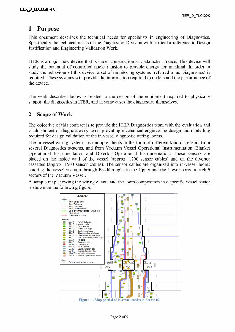
The objective of this contract is to provide the ITER Diagnostics team with the evaluation and establishment of diagnostics systems, providing mechanical engineering design and modelling required for design validation of the in-vessel diagnostic wiring looms.The in-vessel wiring system has multiple clients in the form of different kind of sensors from several Diagnostics systems, and from Vacuum Vessel Operational Instrumentation, Blanket Operational Instrumentation and Divertor Operational Instrumentation. These sensors are placed on the inside wall of the vessel (approx. 1700 sensor cables) and on the divertor cassettes (approx. 1500 sensor cables). The sensor cables are organized into in-vessel looms entering the vessel vacuum through Feedthroughs in the Upper and the Lower ports in each 9 sectors of the Vacuum Vessel.A sample map showing the wiring clients and the loom composition in a specific vessel sector is shown on the following figure.
Figure 1 - Map partial of in-vessel cables in Sector 02
ITER_D_TLCXQK
Page 3 of 9
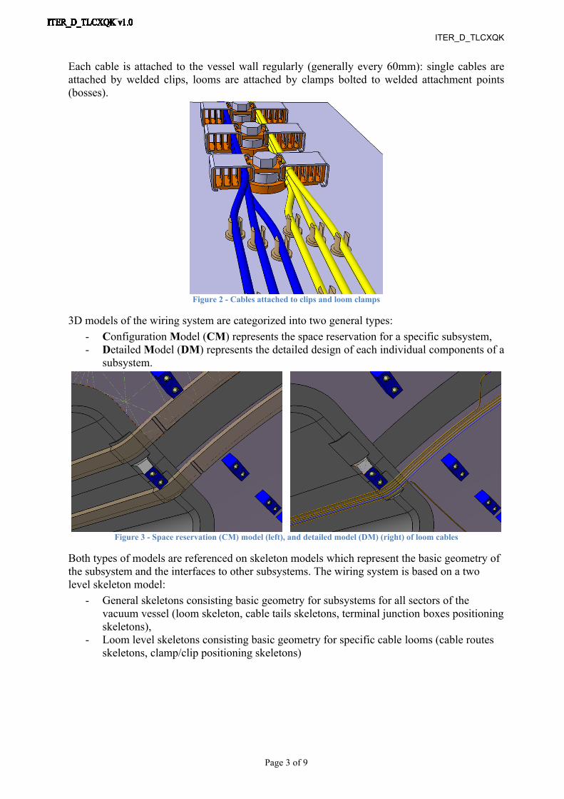
Each cable is attached to the vessel wall regularly (generally every 60mm): single cables are attached by welded clips, looms are attached by clamps bolted to welded attachment points (bosses).
Figure 2 - Cables attached to clips and loom clamps
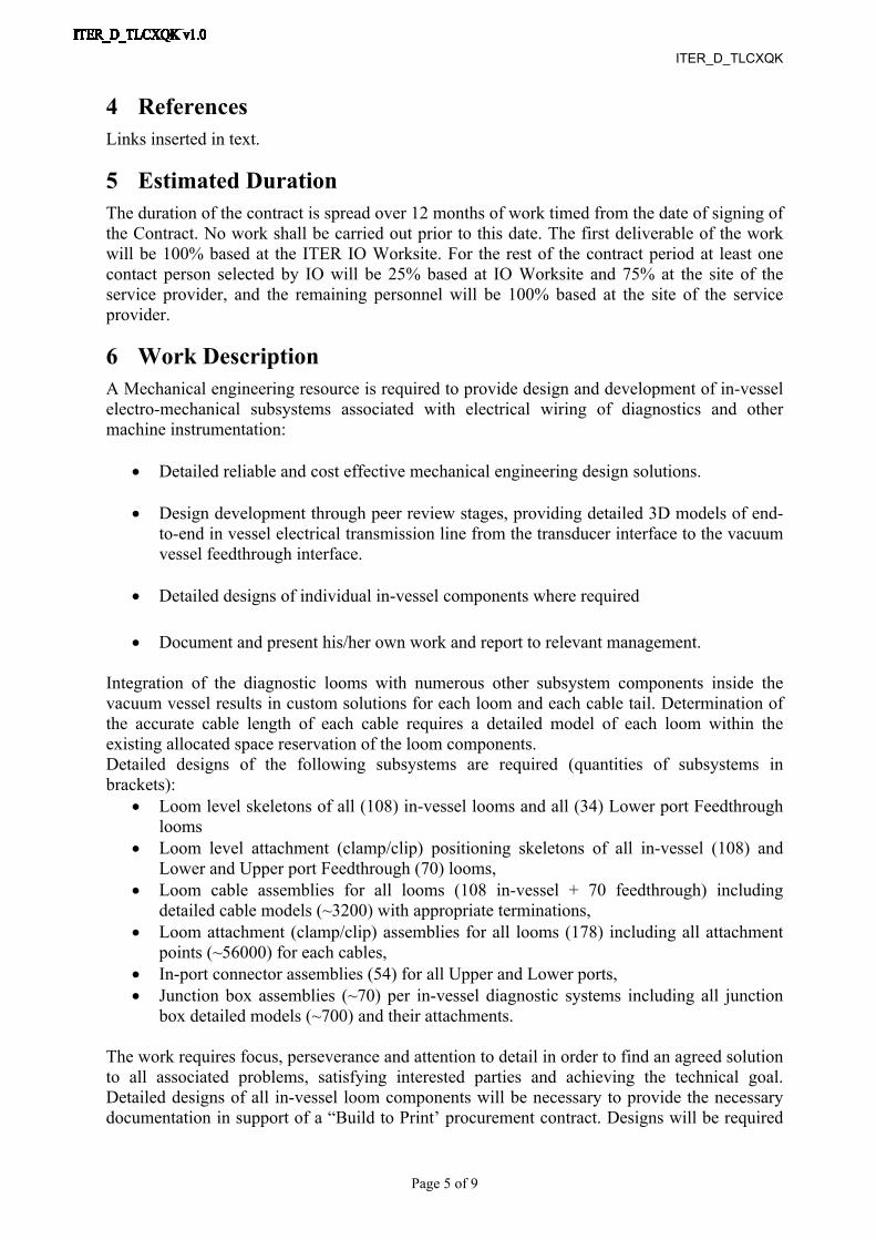
3D models of the wiring system are categorized into two general types:- Configuration Model (CM) represents the space reservation for a specific subsystem,- Detailed Model (DM) represents the detailed design of each individual components of a
subsystem.
Figure 3 - Space reservation (CM) model (left), and detailed model (DM) (right) of loom cables
Both types of models are referenced on skeleton models which represent the basic geometry of the subsystem and the interfaces to other subsystems. The wiring system is based on a two level skeleton model:
- General skeletons consisting basic geometry for subsystems for all sectors of the vacuum vessel (loom skeleton, cable tails skeletons, terminal junction boxes positioning skeletons),
- Loom level skeletons consisting basic geometry for specific cable looms (cable routes skeletons, clamp/clip positioning skeletons)

ITER_D_TLCXQK
Page 4 of 9
Figure 4 - General loom (left) and cable tail (middle) skeletons, and the skeleton of a specific loom (right)
Some of the in-vessel diagnostic systems require the placement of a junction box between the wires of the diagnostic transducer and the loom cables.
Figure 5 - In-vessel junction box
3 DefinitionsIO: ITER OrganizationDA: Domestic AgencySSD: See System DesignCAD Computer aided designCMM Configuration and management modelDM Detailed modelIO-TRO: ITER Organization Technical Responsible Officer.For a complete list of ITER abbreviations see: ITER Abbreviations (ITER_D_2MU6W5).
ITER_D_TLCXQK
Page 5 of 9
4 ReferencesLinks inserted in text.
5 Estimated DurationThe duration of the contract is spread over 12 months of work timed from the date of signing of the Contract. No work shall be carried out prior to this date. The first deliverable of the work will be 100% based at the ITER IO Worksite. For the rest of the contract period at least one contact person selected by IO will be 25% based at IO Worksite and 75% at the site of the service provider, and the remaining personnel will be 100% based at the site of the service provider.
6 Work DescriptionA Mechanical engineering resource is required to provide design and development of in-vessel electro-mechanical subsystems associated with electrical wiring of diagnostics and other machine instrumentation:
Detailed reliable and cost effective mechanical engineering design solutions.
Design development through peer review stages, providing detailed 3D models of end-to-end in vessel electrical transmission line from the transducer interface to the vacuum vessel feedthrough interface.
Detailed designs of individual in-vessel components where required
Document and present his/her own work and report to relevant management.
Integration of the diagnostic looms with numerous other subsystem components inside the vacuum vessel results in custom solutions for each loom and each cable tail. Determination of the accurate cable length of each cable requires a detailed model of each loom within the existing allocated space reservation of the loom components.Detailed designs of the following subsystems are required (quantities of subsystems in brackets):
Loom level skeletons of all (108) in-vessel looms and all (34) Lower port Feedthrough looms
Loom level attachment (clamp/clip) positioning skeletons of all in-vessel (108) and Lower and Upper port Feedthrough (70) looms,
Loom cable assemblies for all looms (108 in-vessel + 70 feedthrough) including detailed cable models (~3200) with appropriate terminations,
Loom attachment (clamp/clip) assemblies for all looms (178) including all attachment points (~56000) for each cables,
In-port connector assemblies (54) for all Upper and Lower ports, Junction box assemblies (~70) per in-vessel diagnostic systems including all junction
box detailed models (~700) and their attachments.
The work requires focus, perseverance and attention to detail in order to find an agreed solution to all associated problems, satisfying interested parties and achieving the technical goal. Detailed designs of all in-vessel loom components will be necessary to provide the necessary documentation in support of a “Build to Print’ procurement contract. Designs will be required
ITER_D_TLCXQK
Page 6 of 9
which meet the demanding mechanical, thermal and UHV requirements for components inside and attached internally to the primary surface. The in vessel looms are based on the use of fixed length, terminated, mineral insulated, stainless steel sheathed, copper cored cables. Detailed designs are required for components and tooling for installing and managing groups of such cable servicing instrumentation and diagnostics distributed throughout the inner surface of the ITER vacuum vessel.
7 Responsibilities
7.1 Contractor’s ResponsibilitiesIn order to successfully perform the tasks in these Technical Specifications, the Contractor shall:• Strictly implement the IO procedures, instructions and use templates;• Provide experienced and trained resources to perform the tasks;• Contractor’s personnel shall possess the qualifications, professional competence and
experience to carry out services in accordance with IO rules and procedures;• Contractor’s personnel shall be bound by the rules and regulations governing the IO ethics,
safety and security rules.
7.2 IO’s ResponsibilitiesThe IO shall:• Nominate the Responsible Officer to manage the Contract;• Organise a monthly meeting(s) on work performed;• Provide offices at IO premises;• Review documents in a timely fashion
8 List of Deliverables and due datesDeliverables are set in units of 4 in-vessel looms or 12 feedthrough looms because of the differing content and complexity. The estimate is based on a total of 96 looms (a few are already completed), 60 Feedthrough looms and 16 diagnostic cassettes.
D # Description Due Dates
D01-03
One deliverable per person
To complete successfully the Catia and Enovia training and familiarisation with ITER engineering environment T0 + 1 month
D04-D25
Complete in Enovia detailed end-to-end models of 3 in-vessel looms including Junction boxes and in-port connectors.
2 deliverables/month
from T0 + 2months to end of
contract.
ITER_D_TLCXQK
Page 7 of 9
(22 in total)
D26-D33
Complete detailed end-to-end models of 2 cassette looms, including all cable and loom management components (8 deliverables).
D34-36
Complete detailed models of Feedthrough looms for:
All upper ports (D34)
All Lower Cryo-ports (D35)
All lower RH ports(D36)
1 deliverable/month from T0+2 months to end of contract
(11 in total)
9 Acceptance CriteriaThe deliverables will be posted in the Contractor’s dedicated folder in IDM, and the acceptance by the IO will be recorded by their approval by the designated IO TRO. These criteria shall be the basis of acceptance by IO following the successful completion of the services. These will be in the form of reports as indicated in section 8, Table of deliverables.
10 Specific requirements and conditionsThe engineer proposed by the bidder to carry out the work described in Section 4 must have:
A professional qualification in Mechanical engineering with relevant experience in mechanical engineering design in a complex technical environment;
Facility and proven competence with modern 3D CAD design packages and related software;
Good technical writing skills; Good inter-personal skills; The ability to be consistent and work well under pressure with good attention to detail; Capability to work in English language, both verbally and written; Able to work with partners and the ITER host to define critical needs; Ability to align work priorities with overall project schedule;
Experience in any or all of the following areas would be a distinct advantage:
Knowledge of ITER diagnostic system; Familiarity with UHV systems; Previous experience of working on an international project; Experience in working with CATIA v5.0/ ENOVIA and adaptation of models for
analysis in ANSYS workbench; Experience in applying ITER-applicable codes and standards (e.g. ASME VIII Div. 2,
ASME III, RCC-MR) to the structural assessment of systems and components in large mechanical engineering structures that have significant electromagnetic loads;
ITER_D_TLCXQK
Page 8 of 9
11 Work Monitoring / Meeting ScheduleThe Contractor shall report progress to the IO Responsible Officer each week. A summary progress report shall be provided on a monthly basis for acceptance of the IO Responsible Officer. The progress report shall include detailed status of each Deliverable and the number of days worked.
12 Delivery time breakdownSee Section 8 “List Deliverables section and due dates”.
13 Quality Assurance (QA) requirementsThe organisation conducting these activities should have an ITER approved QA Program or an ISO 9001 accredited quality system.The general requirements are detailed in ITER Procurement Quality Requirements (ITER_D_22MFG4).Prior to commencement of the task, a Quality Plan must be submitted for IO approval giving evidence of the above and describing the organisation for this task; the skill of workers involved in the study; any anticipated sub-contractors; and giving details of who will be the independent checker of the activities (see Procurement Requirements for Producing a Quality Plan (ITER_D_22MFMW)).Documentation developed as the result of this task shall be retained by the performer of the task or the DA organization for a minimum of 5 years and then may be discarded at the direction of the IO. The use of computer software to perform a safety basis task activity such as analysis and/or modelling, etc. shall be reviewed and approved by the IO prior to its use, in accordance with Quality Assurance for ITER Safety Codes (ITER_D_258LKL).
14 CAD Design Requirements (if applicable)For the contracts where CAD design tasks are involved, the following shall apply:The Supplier shall provide a Design Plan to be approved by the IO. Such plan shall identify all design activities and design deliverables to be provided by the Contractor as part of the contract. The Supplier shall ensure that all designs, CAD data and drawings delivered to IO comply with the Procedure for the Usage of the ITER CAD Manual (2F6FTX), and with the Procedure for the Management of CAD Work & CAD Data (Models and Drawings 2DWU2M).The reference scheme is for the Supplier to work in a fully synchronous manner on the ITER CAD platform (see detailed information about synchronous collaboration in the ITER GNJX6A - Specification for CAD data production in ITER Contracts.). This implies the usage of the CAD software versions as indicated in CAD Manual 07 - CAD Fact Sheet (249WUL) and the connection to one of the ITER project CAD data-bases. Any deviation against this requirement shall be defined in a Design Collaboration Implementation Form (DCIF) prepared and approved by DO and included in the call-for-tender package. Any cost or labour resulting from a deviation or non-conformance of the Supplier with regards to the CAD collaboration requirement shall be incurred by the Supplier.
ITER_D_TLCXQK
Page 9 of 9
15 Safety requirementsITER is a Nuclear Facility identified in France by the number-INB-174 (“Installation Nucléaire de Base”).For Protection Important Components and in particular Safety Important Class components (SIC), the French Nuclear Regulation must be observed, in application of the Article 14 of the ITER Agreement.In such case the Suppliers and Subcontractors must be informed that:
- The Order 7th February 2012 applies to all the components important for the protection (PIC) and the activities important for the protection (PIA).
- The compliance with the INB-order must be demonstrated in the chain of external contractors.
- In application of article II.2.5.4 of the Order 7th February 2012, contracted activities for supervision purposes are also subject to a supervision done by the Nuclear Operator.
For the Protection Important Components, structures and systems of the nuclear facility, and Protection Important Activities the contractor shall ensure that a specific management system is implemented for his own activities and for the activities done by any Supplier and Subcontractor following the requirements of the Order 7th February 2012 (PRELIMINARY ANALYSIS OF THE IMPACT OF THE INB ORDER - 7TH FEBRUARY 2012 (AW6JSB v1.0) ).


![Technical Specifications (In-Cash Procurement) BUTTERFLY ...€¦ · [2.31] NACE RP0287-02, “Field Measurement of Surface Profile of Abrasive Blast-Cleaned Steel Surfaces Using](https://img.pdfslide.net/doc/110x75/5eac7be46fffd769e9600e1f/technical-specifications-in-cash-procurement-butterfly-231-nace-rp0287-02.jpg)
![Technical Specifications (In-Cash Procurement) systems ... 1/17-Plant_Control... · Plant Control Design Handbook for Nuclear control systems ... [19]IEC 61000-6-2, Electromagnetic](https://img.pdfslide.net/doc/110x75/5b1599617f8b9afb0a8d35ce/technical-specifications-in-cash-procurement-systems-117-plantcontrol.jpg)

![Technical Specifications (In-Cash Procurement) BUTTERFLY ...[2.44] IEEE 382-2007, “IEEE Standard for Qualification of Safety-Related Actuators for Nuclear Power Generating Stations”](https://img.pdfslide.net/doc/110x75/5ed294cc218a08345735f956/technical-specifications-in-cash-procurement-butterfly-244-ieee-382-2007.jpg)

![Technical Specifications (In-Cash Procurement) RELIEF VALVES … · 2018-07-16 · [2.35] SSPC-PA-2, “Procedure for Determining Conformance to Dry Coating Thickness Requirements”](https://img.pdfslide.net/doc/110x75/5e9f926f0492ec07e8516e4c/technical-specifications-in-cash-procurement-relief-valves-2018-07-16-235.jpg)