Embed Size (px)
Citation preview

TECHNICAL SPECIFICATIONS
PUMP STATION NO. 2 RELOCATION
PROJECT
IN THE CITY OF EL CENTRO
1
TECHNICAL SPECIFICATIONS DIVISION 1 - GENERAL REQUIREMENTS
SECTION 01025 MEASUREMENT AND PAYMENT
SECTION 01050 FIELD ENGINEERING
SECTION 01060 SAFETY AND HEALTH
SECTION 01200 PROJECT MEETINGS
SECTION 01300 SUBMITTALS
SECTION 01301 SCHEDULE OF VALUES
SECTION 01310 CONTRACTOR'S CONSTRUCTION SCHEDULE
SECTION 01350 PROCEDURE FOR SUBMITTAL OF SUBSTITUE OR “EQUAL”
PRODUCTS
SECTION 01620 PROTECTION OF MATERIALS AND EQUIPMENT
SECTION 01640 SUPPLIERS/MANUFACTURER'S SERVICES DURING
CONSTRUCTION, COMMISSIONING, AND TRAINING OF CITY'S
PERSONNEL
SECTION 01660 INSTALLATION, TESTING, AND COMMISSIONING
SECTION 01700 CONTRACT CLOSEOUT
SECTION 01730 OPERATING AND MAINTENANCE INFORMATION
DIVISION 2 - SITE WORK
SECTION 02100 SITE PREPARATION
SECTION 02140 DEWATERING
SECTION 02160 EXCAVATION SUPPORT SYSTEMS
SECTION 02200 EARTHWORK
SECTION 02210 EXCAVATION, BACKFILLING AND COMPACTION FOR
UTILITIES AND PIPELINES
2
SECTION 02220 EXCAVATION, BACKFILLING AND COMPACTION FOR
STRUCTURES
SECTION 02510 ASPHALT CONCRETE PAVING
DIVISION 3 - CONCRETE
SECTION 03300 CAST IN PLACE CONCRETE
SECTION 03600 GROUT
DIVISION 4 - MASONRY
NOT USED
DIVISION 5 - METALS
NOT USED
DIVISION 6 - WOOD AND PLASTICS
NOT USED
DIVISION 7 - THERMAL AND MOISTURE PROTECTION
NOT USED
DIVISION 8 - DOORS AND WINDOWS
NOT USED
DIVISION 9 - FINISHES
SECTION 09800 PAINTING AND SPECIAL COATING SYSTEMS
SECTION 09876 PLASTIC LINING FOR STRUCTURES
DIVISION 10 - SPECIALTIES
NOT USED
3
DIVISION 11 - EQUIPMENT
SECTION 11223 SUBMERSIBLE CHOPPER PUMPING SYSTEMS
DIVISION 13 - SPECIAL CONSTRUCTION
NOT USED
DIVISION 14 - CONVEYING SYSTEMS
NOT USED
DIVISION 15 - MECHANICAL
SECTION 15070 PLASTIC PIPE
SECTION 15101 GATE VALVES
SECTION 15105 CHECK VALVES
SECTION 15110 PIPING APPURTENANCES AND SPECIALTIES
SECTION 15140 PIPING SUPPORTS
4
SECTION 01025
MEASUREMENT AND PAYMENT
PART 1 - GENERAL
1.1 WORK OF THIS SECTION
A. Payment for the various items of the Bid Schedule, as further specified herein, shall include
all compensation to be received by the CONTRACTOR for furnishing all tools, equipment,
supplies, and manufactured articles, and for all labor and services, operations, and incidentals
appurtenant to the items of WORK being described, as necessary to complete the various
items of the WORK in accordance with the requirements of the Contract Documents,
including all appurtenances thereto, and including all costs of permits and compliance with
the regulations of public agencies having jurisdiction, including Safety and Health
Requirements of the California Division of Industrial Safety and the Occupational Safety and
Health Administration of the U.S. Department of Labor (OSHA). No separate payment will
be made for any item that is not specifically set forth in the Bid Schedule, and all costs
therefore shall be included in the prices named in the Bid Schedule for the various
appurtenant items of WORK.
1.2 RELATED SECTIONS
A. The WORK of the following Sections applies to WORK of this Section. Other Sections of
the WORK not referenced below shall also apply to the extent required for proper
performance of the WORK.
1. Section 00300A, Bid Forms
2. Section 00700H, General Conditions
3. Section 01301, Schedule of Values
1.3 GENERAL CONSTRUCTION
Bid Item 1 Mobilization/Demobilization:
Payment for mobilization and demobilization shall include all compensation for furnishing
all labor, materials, tools, and equipment for mobilization/demobilization, temporary
facilities, equipment rental, meetings, onsite sanitation, cost of bonds and insurances for both
the prime and subcontractors, removal of temporary facilities at the completion of the
project, and all other related mobilization and demobilization costs.
1
Twenty percent (20%) of the mobilization bid price, less retainage will be paid on the initial
billing, provided that all equipment is on-site and bond insurance fees paid. Seventy two
percent (72%) of the mobilization bid price will be paid uniformly in three (3) equal
installments, each being (24%) of the bid price. The final eight percent, plus any remaining
amount left from uniform payments, will be paid upon satisfactory completion of punch list
items, cleaning up and removal of all temporary facilities and equipment from the project site
Bid Item 2 Construction Staking:
Payment for construction staking shall include all compensation for furnishing all labor,
materials, tools, and equipment, to provide and maintain construction staking for the
duration of the project. Payment based on approved schedule of values submitted at
preconstruction meeting.
Bid Item 3 Bypass Pumping:
Payment for bypass pumping shall include all compensation for furnishing all labor,
materials, tools, and equipment, to provide bypass pumping (with 100% backup standby
capability) of wastewater at the project site per the plans. Payment based on approved
schedule of values submitted at preconstruction meeting.
Bid Item 4 Dewatering:
Payment for dewatering shall include all compensation for furnishing all labor, materials,
tools, and equipment, to provide dewatering at the project site per the Technical
Specifications. Payment based on approved schedule of values submitted at preconstruction
meeting.
Bid Item 5 Traffic Control:
Payment for traffic control shall include all compensation for furnishing all labor, materials,
tools, and equipment to provide traffic control as required during the project per the contract
documents. Payment based on approved schedule of values submitted at preconstruction
meeting.
Bid Item 6 Excavation Support Systems:
Payment for excavation support systems (excluding trenchless pits) shall include all
compensation for furnishing all labor, materials, tools, and equipment to design, construct,
and remove all sheeting, shoring, and bracing or other equivalent method of support for the
walls of trenches and open excavations required for construction per the Technical
Specifications. Payment based on approved schedule of values submitted at preconstruction
meeting.
2
Bid Item 7 12” PVC Force Main:
Payment for 12” PVC Force Main shall include all compensation for furnishing all labor,
materials, fittings, tools, and equipment, to provide a complete functioning force main per
the plans. Payment based on approved schedule of values submitted at preconstruction
meeting.
Bid Item 8 24-inch PVC Gravity Sanitary Sewer:
The CONTRACTOR shall furnish, lay, joint, and test all 24-inch diameter PVC sanitary
sewer pipe, as discussed herein in accordance with the Contract Documents.
The WORK shall include all labor, tools, material, and equipment required for installation
including, trenching and excavation work, grinding of pavement, trench and surface repairs,
cut off walls, temporary easements staking, furnishing and installing all pipe, couplings,
fittings, jointing materials, pipe embedment, compaction, backfill, restoration,
connections to existing sewers (excluding laterals and cutoff walls), and testing of the
completed sewer line. Payment based on approved schedule of values submitted at
preconstruction meeting.
Bid Item 9 Manholes (12-feet to 16-feet deep):
The CONTRACTOR shall furnish and install 5’ diameter manholes with 30” frame and
covers, as discussed herein in accordance with the Contract Documents.
The WORK shall include all labor, tools, material, and equipment required for installation
including, precast manholes, frame/cover, concrete collar and base, lining, manhole adapters,
base course, clearing and grubbing, excavation work, grinding of pavement, compaction,
backfill, and restoration of the completed manholes. Payment based on approved schedule
of values submitted at preconstruction meeting.
Bid Item 1 0 Manholes (16-feet to 20-feet deep):
The CONTRACTOR shall furnish and install 5’ diameter manholes with 30” frame and
covers, as discussed herein in accordance with the Contract Documents.
The WORK shall include all labor, tools, material, and equipment required for installation
including, precast manholes, frame/cover, concrete collar and base, lining, manhole adapters,
base course, clearing and grubbing, excavation work, grinding of pavement, compaction,
backfill, and restoration of the completed manholes. Payment based on approved schedule
of values submitted at preconstruction meeting.
3
Bid Item 11 Tunneling:
The CONTRACTOR shall furnish, lay, joint, and test all 24” PVC sanitary sewer pipe, as
discussed herein in accordance with the Contract Documents.
The WORK shall include all labor, tools, material, and equipment required for installation
including, tunneling operations, monitoring and inspection, tunnel permitting, pipe casing,
trenching, shoring, and excavation work for pits, grinding of pavement, furnishing and
installing all ac pavement and base material for pavement repair, testing of the new pavement
and restoration, spoils offhaul, furnishing and installing all pipe, couplings, fittings, jointing
materials, pipe embedment, compaction, backfill, restoration, and testing of the completed
sewer line. Payment based on approved schedule of values submitted at preconstruction
meeting.
Bid Item 12 Pump Station:
The CONTRACTOR shall furnish, install, and test the sewer pump station, as discussed
herein in accordance with the Contract Documents.
The WORK shall include all labor, tools, material, and equipment required for installation
including, monitoring and inspection, furnishing and installing all pipe, pumps, couplings,
fittings, and testing of the pumping system. Payment based on approved schedule of
values submitted at preconstruction meeting.
Bid Item 13 Wet Well:
The CONTRACTOR shall excavate, furnish, install, and test the 10 foot diameter by 27
feet deep wet well, as discussed herein in accordance with the Contract Documents.
The WORK shall include all labor, tools, material, and equipment required for installation
including lining the interior surfaces with Zebron or similar approved product, including
backfill, and testing. Payment based on approved schedule of values submitted at
preconstruction meeting.
Bid Item 14 125 Kw Generator:
The CONTRACTOR shall furnish and install the 125 Kw Generator, as discussed herein
in accordance with the Contract Documents.
The WORK shall include all labor, tools, material, and equipment required for installation
including, Generator, Automatic Transfer Switch, and Generator Pad. Payment based on
approved schedule of values submitted at preconstruction meeting.
4
Bid Item 15 Chain Link Fencing:
The CONTRACTOR shall furnish and install a 6’ chain link fence complete with 3
strands of barb wire, a 16’ vehicle access gate, and a 3’ personnel gate, as discussed
herein in accordance with the Contract Documents.
The WORK shall include all labor, tools, material, and equipment required for installation
including, clearing and grubbing, furnishing and installing all posts and fencing.
Payment based on approved schedule of values submitted at preconstruction meeting.
Bid Item 16 Decommissioning of Existing Pump Station and Sewer Lines:
The CONTRACTOR shall decommission the Existing Pump Station and Sewer Lines as
discussed herein in accordance with the Contract Documents.
The WORK shall include all labor, tools, material, and equipment required for decommission
including, plugging pipelines, sand/cement slurry fill, partial demolition of manholes and
piping, backfill, compaction, disposal of materials, and restoration. Parts to become
property of the Contractor. Payment based on approved schedule of values submitted at
preconstruction meeting.
Bid Item 17 Erosion Control:
Payment for Erosion Control shall include all compensation for implementing and updating a
Water Pollution Control Program (WPCP) per the Technical Specifications, preparing
erosion control plans for work in the City limits, and all compensation for furnishing,
installing, maintaining and removing erosion control measures and BMPs per the Technical
Specifications.
WORK INCLUDED IN OVERALL CONTRACT PRICE
The cost of any WORK not specifically called for or set forth in the Bid Proposal as part of
Lump Sum or Unit Price Items, but which is considered necessary for the proper execution of
the WORK, shall be considered as an obligational requirement of the CONTRACTOR to
furnish such labor, equipment, materials and appurtenances as part of the Total Contract
Price for the complete construction of the WORK in accordance with the Contract
Documents, and no separate payment will be made. Such WORK shall include, but is not
limited to: removal and proper disposal of unsuitable materials; demolition; providing
operation and maintenance manuals; project documentation by videotape and photos;
temporary facilities; traffic control; testing; materials and equipment for required testing;
conforming to all requirements set forth in the project permits; startup services of factory
trained service engineers; all other general requirements and industry standards; and all
WORK shown on the Contract Drawings and required by the Specifications.
5
1.4 RETENTION
A. The OWNER shall retain a percentage of each progress payment in accordance with Section
00700H, GENERAL CONDITIONS. The retained amount is available for the protection and
payment of the person(s), mechanics, subcontractors, or material men who perform labor
upon the Contract or WORK thereunder, and the persons who supply such person(s), or
subcontractors with components and supplies for carrying on such WORK.
B. Pursuant to Section 22300 of the Public Contract Code of the State of California, the
CONTRACTOR has the option, at his expense, to deposit securities with an Escrow Agent
as a substitute for retention earnings required to be withheld by the CITY. Securities eligible
for such substitution are bank or savings and loans certificates of deposit or such securities
that are eligible for investment pursuant to Government Code Section 16430. As to any such
security or securities so substituted for monies withheld, the CONTRACTOR shall be the
beneficial owner of same and shall receive any interest thereon. Such security shall, at the
request and expense of the CONTRACTOR, be deposited with a State or Federally Chartered
bank as the escrow agent who shall pay such monies to the CONTRACTOR upon
notification by the CITY that payment can be made. Such notification will be given at the
expiration of thirty-five (35)-days from the date of acceptance of the WORK, or as prescribed
by law, provided however, that there will be a continued retention of the necessary securities
to cover such amounts as are required by law to be withheld by properly executed and filed
notices to stop payment, or as may be authorized by the contract to be further retained.
PART 2 – PRODUCTS (NOT USED)
PART 3 – EXECUTION (NOT USED)
** END OF SECTION **
6
SECTION 01050
FIELD ENGINEERING
PART 1 - GENERAL
1.01 CONSTRUCTION STAKING
A. General
The Contractor will establish the reference bench marks and base lines identified on the
drawings, and shall develop and make such additional surveys as are needed for
construction, such as control lines, slope stakes, batter boards, stakes for pipe locations and
other working points, lines, and elevations.
B. Datum
The plane of reference for elevations used in the plans and specifications shall be 1,000
feet below mean sea level (MSL).
C. Horizontal and Vertical Control
From the base line and temporary bench mark described herein and the existing structures,
the City shall complete the layout of the work and shall be responsible for all
measurements that may be required for execution of the work to the location and limit
marks prescribed in the specifications or on the Contract Drawings, subject to such
modifications as the Engineer may require to meet changed conditions or as a result of
necessary modifications to the contract work.
D. Contractor's Layout
The Contractor shall furnish such stakes, equipment, tools, materials, and all labor as
required in laying out any parts of the work from the base line and bench marks. It shall be
the responsibility of the Contractor to maintain and preserve all base line stakes and other
marks established until authorized to remove them; and, if such stakes or other marks are
destroyed by the Contractor, or through his negligence, prior to their authorized removal,
they may be replaced by and at the discretion of the Engineer and the expense of
replacement shall be borne by the Contractor and will be deducted from any amounts due
or to become due to the Contractor.
**END OF SECTION**
7
SECTION 01060
SAFETY AND HEALTH
1.01 GENERAL
The sewer collection system is exposed to raw untreated wastewater. The Contractor
certifies that he is experienced and qualified to anticipate and meet the safety and health
requirements of this project.
Workmen involved in the removal, renovation, or installation of the collection system may
be exposed to disease-producing organisms in wastewater. The Contractor shall require his
personnel to observe proper hygienic precautions.
Solvents, gasoline, and other hazardous materials enter the collection system with
incoming sewage, and, therefore, certain areas are hazardous to open flame, sparks, or
unventilated occupancy. The Contractor shall take measures to assure his personnel
observe proper safety precautions when working in these areas.
1.02 SAFETY AND HEALTH REGULATIONS
The Contractor shall comply with Safety and Health Regulations for Construction,
promulgated by the Secretary of Labor under the Contract Work Hours and Safety
Standards Act, as amended and as set forth in Title 29, Code of Federal Regulations (CFR).
Copies of these regulations may be obtained from Labor Building, 14th and Constitution
Avenue NW, Washington, DC 20013.
The Contractor shall also comply with the provisions of the Federal and State of California
Occupational Safety and Health Act (OSHA), as amended.
8
SECTION 01200
PROJECT MEETINGS
PART 1 - GENERAL
1.01 PRECONSTRUCTION MEETING
A preconstruction meeting will be held within ten working days of Award of the Contract.
The purpose of the meeting will be to discuss the various requirements of the specifications
and the Contractor's responsibilities with regard to process control, schedule, submittals,
traffic control, and safety. The Contractor shall not commence construction work until after
the preconstruction meeting and issuance of a Notice to Proceed.
1.02 MONTHLY STATUS MEETINGS
Regular monthly construction progress meetings shall be held throughout the construction
period from the time the Contractor begins work until the acceptance of the work by the
City. The Construction Manager and representatives of the City will attend the meeting.
The Contractor shall be represented by his designated construction manager and
representatives of any major subcontractor whose work will be discussed at the meeting.
The purpose of the meeting shall be as follows:
A. Review of progress of the work during the preceding month and the job to date for
compliance with the approved construction schedule as described in Section 01310,
CONTRACTOR'S CONSTRUCTION SCHEDULE.
B. Discuss work and coordination of activities that will be required for the completion of
all work scheduled for the following month.
C. Discuss additional measures required to bring the progress of the work into
compliance with the approved schedule if required to satisfy the provisions of the
contract.
D. Review status of submittals, change orders, directives, and equipment delivery dates.
E. Any additional items of concern to the City or Construction Manager.
1.03 WEEKLY MEETINGS
The Contractor's superintendent shall meet with the Construction Manager at the beginning
of each week to discuss the activities scheduled for the following week and the compliance
of the work with the schedule established at the previous monthly status meeting.
9
1.04 ADDITIONAL MEETINGS
Additional meetings with the Construction Manager, City, Designer and the Contractor
will be called by the Construction Manager to resolve disputes on various items of work on
the project, including, but not limited to, progress payments, design omissions or conflicts,
and changes in work and/or schedule.
**END OF SECTION**
10
SECTION 01310
CONTRACTOR'S CONSTRUCTION SCHEDULE
PART 1 - GENERAL
1.01 SCOPE
This section specifies the procedures for preparing the construction schedule used for
planning and managing construction activities. The schedule provides a basis for
determining the progress status of the project relative to the completion time and specific
dates.
1.02 DESCRIPTION
The Contractor shall prepare a time scale network schedule using a critical path method. A
general guide for preparing such a schedule is contained in The Use of CPM in
Construction, a Manual for Contractors, published by the Associated General Contractors
of America.
The schedule shall depict all significant construction activities and all items of work listed
in the breakdown of contract prices submitted by the Contractor in accordance with the bid
schedule. The dependencies between activities shall be indicated so that it may be
established what effect the progress of any one activity has on the schedule.
Detailed network activities shall include, in addition to construction activities, the
submittal and approval of samples of material and shop drawings, the procurement of
critical materials and equipment, and their installation and testing. All submittals of
equipment and materials in Divisions 11, 13, 14, 15 and 16 shall be shown on the schedule
together with appropriate allowances for review and delivery times, installation, testing and
training as appropriate. All activities of the City and Construction Manager that affect the
progress of the work shall be shown. Any omission of work from the schedule required for
contract compliance shall not excuse the Contractor from completing such work within any
applicable completion date.
Completion time shall be shown on the schedule. Activities making up the critical path
shall be identified.
No activity on the schedule shall have a duration longer than 21 calendar days except
activities comprising only fabrication and delivery, which may extend for more than 21
calendar days. Activities which exceed these limits shall be divided into more detailed
components. The scheduled duration of each activity shall be based on the work being
performed during the normal 40-hour work week with allowances made for legal holidays
and normal weather conditions.
The Contractor shall not work on legal holidays except by permission of the Construction
11
Manager. Legal holidays are defined as the holidays observed by the respective job
classifications as defined by the California Department of Industrial Relations, Prevailing
Wage Determinations. The Contractor shall notify the Construction Manager by Friday of
their intent to work on any immediately following Saturday or Sunday. Delays to project
completion experienced during holidays or weekends without proper permission or notice
will not be considered to be the responsibility of the City or Construction Manager.
Schedules shall be realistic. Contractors shall be required to show use of all calendar days
allowed for completion in their schedule or accept a no cost change order reducing the
number of days allowed for the completion of the work to the amount shown on the
proposed and approved schedule.
1.03 SUBMITTAL PROCEDURES
Within 20 days after the date of the Notice of Proceed, the Contractor shall complete a
construction schedule conforming to Part 1.02, Description, and representing in detail all
planned procurement and onsite construction activities. The schedule shall be prepared on
reproducible paper and may be in draft form with legible freehand lines and lettering. The
Contractor shall submit the original and three copies to the Construction Manager in
accordance with Section 01300, SUBMITTALS.
No progress payments shall be made prior to the acceptance of the CPM schedule. Failure
to resubmit updated schedules as required herein shall result in an increase in the retentions
of the amounts due the Contractor as described in these contract documents.
Within 14 calendar days after receipt of the submittal, the Construction Manager shall
review the submitted schedule and return two copies of the marked up original to the
Contractor. If the Construction Manager finds that the submitted schedule does not comply
with specified requirements, the corrective revisions will be noted on the submittal copy
returned to the Contractor for corrections and resubmittal as specified in Section 01300,
SUBMITTALS.
1.04 SCHEDULE REVISIONS
Revisions to the accepted construction schedule may be made only with written approval
of the Contractor and the City. Changes in timing for activities which are not on the critical
path may be modified with written agreement of the Contractor and Construction Manager.
A change affecting the timing of any activity on the critical path, the completion time and
specific dates and work sequencing may be made only with the approval of the
Construction Manager and the City.
1.05 PROJECT STATUS UPDATE
A jobsite meeting will be held each month at a time mutually agreed upon by the
Contractor, Construction Manager and City to review the construction progress for
compliance with the approved schedule. Weekly meetings will also be held between the
Contractor and Construction Manager to review the progress of the work of the previous
week and to coordinate the work of the subsequent week. The schedule shall be revised
12
whenever: the schedule does not represent the progress of the work; equipment submittals,
approvals or deliveries make rescheduling of activities necessary; any change to the
sequence of activities occurs or any change occurs to activities on the critical path; or when
a contract modification necessitates a revision to the schedule. Updates to the schedule
shall, at a minimum, be required on a monthly basis.
**END OF SECTION**
13
SECTION 01300
SUBMITTALS
PART 1 - GENERAL
1.01 GENERAL
Where required by the specifications, the Contractor shall submit descriptive information
which will enable determination of whether the Contractor's proposed materials,
equipment, or methods of work are in general conformance to the design concept and in
compliance with the drawings and specifications. The information to be submitted shall
consist of drawings, specifications, descriptive data, certificates, samples, test results and
such other information, all as specifically required in the specifications. In some instances,
specified submittal information describes some, but not all, features of the material
equipment, or method of work. Features not requiring submittals shall be as specified.
Submittal review shall be only for general conformance with the design concept and
general compliance with the information given in the contract documents. It shall not
include review of quantities, dimensions, weights or gages, fabrication processes,
construction safety precautions, all of which are the sole responsibility of the Contractor.
Review of a specific item shall not indicate acceptance of an assembly of which the item is
a component. The Engineer shall not be required to review, and shall not be responsible
for, any deviations from the contract documents not clearly noted by the Contractor, nor
shall the Engineer be required to review partial submissions or those for which submissions
for correlated items have not been received.
The Contractor may authorize material or equipment suppliers to deal directly with the
Engineer with regard to such submittals; however, ultimate responsibility for the accuracy
and completeness of the information contained in the submittal shall remain with the
Contractor.
1.02 CONTRACTOR'S RESPONSIBILITIES
The Contractor shall be responsible for the accuracy and completeness of the information
contained in each submittal and shall assure that the material, equipment, or method of
work shall be described in the submittal. The Contractor shall verify that all features of all
products conform to the requirements of the specifications and drawings. The Contractor
shall verify that all features of all products conform to the requirements of the
specifications and drawings. The Contractor shall insure that there is no conflict with other
submittals and shall notify the Engineer in each case where his submittal may affect the
work of City or others. The Contractor shall insure coordination of submittals among the
related crafts and subcontractors.
Immediately following Award of the Contract, the Contractor shall review the plans and
specifications and shall prepare a list of all submittals anticipated on the project and shall
14
submit this list to the Engineer. Items not on the list but requiring review shall be added to
the list as requested by the Engineer at any time during the construction.
1.03 TRANSMITTAL PROCEDURE
A. General
Submittals regarding material and equipment shall be accompanied by a transmittal form.
A separate form shall be used for each specific item, class of material, equipment, and for
items specified in separate, discrete sections. Submittals for various items shall be made
with a single form when the items taken together constitute a manufacturer's package or are
so functionally related that expediency indicates checking or review of the group or
package as a whole.
A unique number, sequentially assigned, shall be noted on the transmittal form
accompanying each item submitted. Submittal numbers shall have the following format:
"XXX-YYYYY-ZZ"; where "XXX" is the sequential number assigned by the Contractor,
"YYYYY" is the specification section number covered by the submittal, and "ZZ" is the
sequential number of the submittal ("01" for the first submittal, "02" for the second
submittal, etc.). Resubmittals shall have the same submittal number format; where "XXX"
is the originally assigned submittal number.
Submittal 25-11350-02, for example, would be the second submittal (first resubmittal) of
submittal 25 covering Section 11350.
B. Deviation from Contract
If the Contractor proposes to provide material, equipment, or method of work which
deviates from the contract documents, he shall so indicate on the transmittal form
accompanying the submittal copies.
C. Submittal Completeness
Submittals which do not contain all the information required to be submitted, including
deviations, are not acceptable and will be returned without review.
D. Requests for Substitution
The Contractor may offer material or equipment of equal or better quality and performance
in substitution for those specified. The City will consider offers for substitution only from
the Contractor and will not acknowledge or consider such offers from suppliers,
distributors, manufacturers, or subcontractors. The Contractor's offers of substitution shall
be made in writing to the Engineer and shall include sufficient data to enable the Engineer
to assess the acceptability of the material or equipment for the particular application and
requirements.
If the offered substitution necessitates changes to or coordination with other portions of the
work, the data submitted shall include drawings and details showing such changes.
15
Contractor agrees to perform these changes as part of the substitution of material or
equipment at no additional cost to City. Within 21 calendar days after receipt of the offer
of substitution, the Engineer will review the material submitted by the Contractor and
advise the Contractor of objections, if any, to the proposed substitution or if further
information is required. Upon notification by the Engineer, the Contractor shall either
provide material or equipment which complies with project specifications or furnish
requested additional information. While the Engineer might not take any objections to the
proposed substitution, such action shall not relieve the Contractor from responsibility for
the efficiency, sufficiency, quality and performance of the substitute material or equipment,
in the same manner and degree as the material and equipment specified by name. Any cost
differential associated with a substitution shall be reflected in the offer and the contract
documents shall be modified by a change order.
1.04 REVIEW PROCEDURE
When the contract documents require a submittal, the Contractor shall submit copies of the
specified information as follows unless otherwise specified:
A. One reproducible original of all the submitted information. When individual sheets in
the submittal exceed 8 1/2" x 11", a sepia shall be submitted.
B. Five copies of all the submitted information.
C. Submittals shall be delivered or mailed to:
The Construction Manager (To be determined)
Unless otherwise specified, within 21 calendar days after receipt of the submittal, the submittal
will be reviewed and three copies of the marked-up reproducible original will be returned to the
Contractor. The reproducible original shall be retained by the Engineer. The returned submittal
shall indicate one of the following actions:
A. If the review indicates that the material, equipment, or work method is in general
conformance with the design concept and complies with the drawings and specifications,
submittal copies will be marked "NO EXCEPTIONS TAKEN." In this event, the
Contractor may begin to implement the work method or incorporate the material or
equipment covered by the submittal.
B. If the review indicates limited corrections are required, copies will be marked "MAKE
CORRECTIONS NOTED." The Contractor may begin implementing the work method or
incorporating the material and equipment covered by the submittal in accordance with the
noted corrections. Where submittal information will be incorporated in operation and
maintenance information, a corrected copy shall be provided.
C. If the review reveals that the submittal is insufficient or contains incorrect data, copies will
be marked "REVISE AND RESUBMIT." Except at his own risk, the Contractor shall not
undertake work covered by this submittal until it has been revised, resubmitted and
returned marked either "NO EXCEPTIONS TAKEN" or "MAKE CORRECTIONS
16
NOTED."
D. If the review indicates that the material, equipment, or work method is not in general
conformance with the design concept or in compliance with the drawings and
specifications, copies of the submittal will be marked "REJECTED". Submittals with
deviations which have not been identified clearly may be rejected. Except at his own risk,
the Contractor shall not undertake the work covered by such submittals until a new
submittal is made and returned marked either "NO EXCEPTIONS TAKEN" or "MAKE
CORRECTIONS NOTED".
Following the initial review, two "resubmittals" will be allowed by the Engineer prior to a
"backcharge" for engineering review and administration costs being incurred by the
Contractor. The "backcharge" will be deducted from any amounts due the Contractor.
1.05 EFFECT OF REVIEW OF CONTRACTOR'S SUBMITTALS
Review of drawings, methods of work, or information regarding materials or equipment the
Contractor proposes to provide shall not relieve the Contractor of his responsibility for
errors therein and shall not be regarded as an assumption of risks or liability by the City, or
by any officer or employee thereof, or by any engineering firm conducting such review on
behalf of the City, and the Contractor shall have no claim under the contract on account of
the failure, or partial failure, of the method of work, material, or equipment so reviewed. A
mark of "NO EXCEPTIONS TAKEN" or "MAKE CORRECTIONS NOTED" shall mean
that the City has no objection to the Contractor, upon his own responsibility, using the plan
or method of work proposed, or providing the materials or equipment proposed.
**END OF SECTION**
17
SECTION 01301
SCHEDULE OF VALUES
PART 1 - GENERAL
1.1 WORK OF THIS SECTION
A. The CONTRACTOR shall develop and submit a Schedule of Values (lump sum price
breakdown) to be incorporated into the cost loading function of the Construction Schedule as
specified in Section 01310. Monthly progress payment amounts shall be determined from
the monthly progress updates of the Construction Schedule activities.
The Schedule of Values shall be developed independent of, but simultaneous with the
development of the Construction Schedule activities and logic as follows:
1.2 RELATED SECTIONS
A. The WORK of the following Sections apply to WORK of this Section. Other Sections of the
Specifications, not referenced below, shall also apply to the extent required for proper
performance of the WORK.
1. Section 01025, Measurement and Payment
2. Section 01200, Project Meetings
3. Section 01300, Submittals
4. Section 01310, Construction Schedules
1.3 SUBMITTALS
A. Preliminary Schedule of Values.
B. Detailed Schedule of Values.
18
PART 2 - PRODUCTS
2.1 PRELIMINARY SCHEDULE OF VALUES
A. The CONTRACTOR shall submit a preliminary Schedule of Values for the major
components of the WORK at the Preconstruction Conference. The listing shall include a
detailed breakdown of cost for each lump sum bid item specified in Section 01025,
MEASUREMENT AND PAYMENT.
The CONTRACTOR and CONSTRUCTION MANAGER shall meet and jointly review the
preliminary Schedule of Values, and make any adjustments in value allocations if, in the
opinion of the CONSTRUCTION MANAGER, these are necessary to establish fair and
reasonable allocation of values for the major components of the WORK. Front end loading
of the Schedule of Values will not be permitted. The CONSTRUCTION MANAGER may
require reallocation of major WORK components from items in the above listing if such
reallocation is necessary in the opinion of the CONSTRUCTION MANAGER.
2.2 DETAILED SCHEDULE OF VALUES
A. The CONTRACTOR shall prepare and submit a detailed Schedule of Values to the
CONSTRUCTION MANAGER within 15-days from acceptance of preliminary schedule of
values that is submitted within 15-days of NTP per 3.1 A this section. The detailed Schedule
of Values shall be based on the accepted preliminary Schedule of Values for major
components of the WORK. Sufficient breakdown of the construction activities shall be
provided to allow development of a detailed Schedule of Values sufficient to determine
appropriate monthly progress payment amounts through cost loading of the Construction
Schedule activities. The CONSTRUCTION MANAGER shall determine the acceptable
numbers, details and description of values established. If, in the opinion of the
CONSTRUCTION MANAGER, a greater number of items or construction activities than
those proposed by the CONTRACTOR are necessary, the CONTRACTOR shall add the
additional items so identified by the CONSTRUCTION MANAGER.
1. The minimum detail of breakdown of the major components of the WORK is indicated
in Part 1 of Section 01025 Measurement and Payment. Greater detail shall be provided
as directed by the CONSTRUCTION MANAGER.
a. All other WORK not specifically included in the above items shall be detailed as
necessary for establishment of cost and Construction Schedule activity items.
The CONTRACTOR and CONSTRUCTION MANAGER shall meet and jointly
review the detailed Schedule of Values within 35-days from the date of Notice to
Proceed. The value allocations and extent of detail shall be reviewed to determine any
necessary adjustments to the values and to determine if sufficient detail has been
proposed to provide cost loading of the Construction Schedule activities.
19
2. Following acceptance of the detailed Schedule of Values, the CONTRACTOR shall
incorporate the values into the cost loading portion of the Construction Schedule. The
Construction Schedule activities and logic shall have been developed concurrent with
development of the detailed Schedule of Values; however, it shall be necessary to
adjust the detailed Schedule of Values to correlate to individual Construction Schedule
activities. Because of the independent but simultaneous development of the Schedule
of Values and the Construction Schedule activities, it is anticipated that instances will
occur where interfacing these two documents will require changes to both documents.
Construction Schedule activities may need to be added to accommodate the detail of the
Schedule of Values. Schedule of Value items may need to be added to accommodate
the details of the Construction Schedule activities. Where such instances arise, the
CONTRACTOR shall propose changes to the Schedule of Values and to the
Construction Schedule activities acceptable to the CONSTRUCTION MANAGER to
satisfy the Construction Schedule cost loading requirements.
2.3 CROSS REFERENCE LISTING
A. To assist in the correlation of the Schedule of Values and the Construction Schedule, the
CONTRACTOR shall provide a Cross Reference Listing which shall be furnished in two
parts. The first part shall list each Scheduled Activity with the breakdown of the respective
valued items making up the total cost of the activity. The second part shall list the valued
item with the respective Scheduled Activity or Activities that make up the total cost
indicated. In the case where a number of schedule activities make up the total cost for a
valued item (shown in the Schedule of Values) the total cost for each scheduled activity
should be indicated.
B. These listings shall be updated and submitted in conjunction with the Construction Schedule
monthly submittals as stated in Section 01310, CONSTRUCTION SCHEDULE.
C. Approved change orders reflected in the Construction Schedule shall be incorporated into the
Schedule of Values as a single unit identified by the change order number.
2.4 CHANGES TO SCHEDULE OF VALUES
A. Changes to the Construction Schedule, which add activities not included in the original
schedule but included in the original WORK (schedule omissions), shall have values
assigned, and other activity values shall be reduced to provide equal value adjustment
increases for added activities as approved by the CONSTRUCTION MANAGER.
B. In the event that the CONTRACTOR and CONSTRUCTION MANAGER agree to
make adjustments to the original Schedule of Values because of inequities discovered
in the original accepted detailed Schedule of Values, increases and equal decreases to
values for activities may be made.
PART 3 – PRODUCTS (NOT USED)
** END OF SECTION **
SECTION 01350
PROCEDURE FOR SUBMITTAL OF SUBSTITUE OR “EQUAL” PRODUCTS
The Contractor shall, at its expense, furnish data concerning items offered by it as
equivalent to those specified. The Contractor shall have the material tested as required
by the Engineer to determine that the quality, strength, physical, chemical or other
characteristics, including durability, finish, efficiency, dimensions, service, and
suitability are such that the item will fulfill its intended function.
Test methods shall be subject to the approval of the Engineer. Test results shall be
reported promptly to the Engineer, who will evaluate the results and determine if the
substitute item is equivalent. The Engineer’s finding shall be final. Installation and the
use of a substitute item shall not be made until approved by the Engineer.
If a substitute offered by the Contractor is not found to be equal to the specified
material, the Contractor shall furnish and install the specified material.
The specified Contract completion time shall not be affected by any circumstance
development from the provisions of this section.
**END OF SECTION**
SECTION 01620
PROTECTION OF MATERIALS AND EQUIPMENT
PART 1 - GENERAL
1.01 GENERAL
Materials and equipment shall be shipped, handled, stored, and installed by methods
which will prevent damage to the items. Damaged items will not be permitted as part of
the work except in cases of minor damage that have been satisfactorily repaired and are
acceptable to the Construction Manager.
1.02 PIPE
Pipe and appurtenances shall be handled, stored, and installed as recommended by the
manufacturer. Pipes with soft coatings such as coal tar enamel, paint, or the like shall be
stored to protect the coating from physical damage or other deterioration and shall only
be handled with padded, wide slings. Pipes shipped with interior bracing shall have the
bracing removed only when recommended by the pipe manufacturer.
1.03 EQUIPMENT
A. Definition
For the purpose of this section, equipment refers to any mechanical, electrical, or
instrumentation devices, and other items with one or more moving parts requiring an
electrical, pneumatic, electronic or hydraulic connection.
B. Packing and Marking
All equipment shall be adequately and effectively protected against damage from
moisture, dust, handling, or other cause during transport from manufacturer's premises
to site. Each item or package shall be clearly marked with the number unique to the
specification reference covering the item. Each separate portion of equipment shall
receive, as far as practicable, a fitting or distinguishing mark which shall be shown on
the packing lists. Stiffeners shall be used where necessary to maintain shapes and to
give rigidity. Parts of equipment shall be delivered in assembled or subassembled units
where possible.
C. Identification of Equipment
All equipment items and valves with an assigned equipment number shall have affixed
to them in a prominent location, a label or tag displaying the assigned equipment
number. Equipment item and valves lacking a number shall have a similar tag providing
a unique description of the item. Markers shall be of stainless steel or aluminum, affixed
to the item in question with stainless steel fasteners or as otherwise approved by the
Construction Manager. Plastic tape labels will not be acceptable.
D. Storage of Equipment
During the interval between delivery and installation, all equipment to be incorporated
into the project shall be stored in enclosed, weather-tight bonded commercial
warehouses equipped with fire detection and sprinkler systems. Environmental controls
such as heaters or protective encapsulation shall be provided to ensure against
condensation and moisture damage. In the event prolonged (more than 90 days) storage
is required for any item of rotative equipment, the Contractor shall institute a preventive
maintenance program which shall include grease protection of bare metal surfaces,
periodic indexing of rotating parts, renewal of grease in bearings and any procedures
recommended by the manufacturer. The Contractor shall maintain adequate records to
demonstrate full compliance with these requirements. All equipment shall be available
for inspection by the Construction Manager.
No materials shall be allowed to be stored within the Right-of-Way. It is the
Contractor’s responsibility to legally store equipment and materials associated with the
performance of the work. No staging, storage, or stockpiling within public right-of-way
will be allowed. If the Contractor has arranged for temporary storage on private
property, the Contractor shall provide to the City a copy of the written agreement
between the landowner and the Contractor.
E. Protection of Equipment after Installation
After each equipment item is installed, it shall be protected from damage, including but
not limited to, dust, abrasive particles, debris and dirt generated by the placement,
chipping, sandblasting, cutting, finishing and grinding of new or existing concrete,
terrazzo and metal; and the fumes, particulate matter, and splatter from welding, brazing
and painting of new or existing piping and equipment. The Contractor is advised that as
a minimum, vacuum cleaning, blowers with filters, protective shieldings, and other dust
suppression methods will be required at all times to adequately protect all equipment.
During concreting, including finishing, all equipment that may be affected by cement
dust must be completely covered. During painting operations, all grease fittings and
similar openings shall be covered to prevent the entry of paint. Electrical switchgear,
unit substation, and motor load centers shall not be installed until after all concrete work
and sandblasting in those areas have been completed and accepted.
1.04 DELIVERY OF MATERIAL OR EQUIPMENT
The City's personnel or representatives will not accept materials or equipment deliveries
for the Contractor.
**END OF SECTION**
SECTION 01640
SUPPLIERS/MANUFACTURER'S SERVICES DURING CONSTRUCTION,
COMMISSIONING, AND TRAINING OF CITY'S PERSONNEL
PART 1 - GENERAL
1.01 DESCRIPTION
This section specifies the services of the supplier's and manufacturer's representatives
which the Contractor shall supply during construction, commissioning, and training of
the City's personnel for plant operation as required in the respective sections.
1.02 DEFINITIONS
A. Labor Days
One labor-day equals one person for 8 hours straight time, exclusive of Saturday,
Sunday, or holidays.
1.03 PROCEDURE IN PROVIDING SERVICES
A. General
The Contractor shall include and pay all costs for all appropriate manufacturers’
services, including, but not limited to, those specified herein. Where a minimum amount
of time is stated in the Project Specifications for manufacturer's services, any additional
time required to perform the specified services shall be at no additional cost to the City.
B. Fulfillment of Specified Minimum Services
Only those suppliers' and manufacturer's services receiving prior approval by the
Construction Manager shall act to fulfill the specified minimum labor day requirements
for such supplier and manufacturer's services. All requests to the Construction Manager
for prior approval shall 1) be in writing; 2) be submitted not less than 14 calendar days
prior to the providing of the subject services; 3) state the service to be provided and all
required supporting information; 4) state the technical representative's qualifications;
and 5) state the reason(s) why the timing of the service is appropriated. Requests made
to the Construction Manager less than 14 calendar days prior to the providing of
suppliers' and manufacturer's services may not receive consideration and response prior
to the times the services are provided. The Contractor is advised that, nonetheless, in
such cases the requested services may be disapproved because of non-fulfillment of the
specified minimum labor day requirements. All responses to the Contractor, approving
or disapproving requests for prior approval, shall be in writing. Visits of suppliers and
manufacturers and their representatives to the jobsite or training classroom without prior
approval as provided herein will not act to fulfill the specified minimum labor day
requirements.
1.04 CONSTRUCTION
Competent and experienced technical representatives thoroughly familiar with the
equipment supplied with a minimum experience of five years performing comparable
services shall represent the manufacturers of all equipment and systems as may be
necessary to resolve assembly or installation problems at the worksite which are
attributable to, or associated with, the equipment furnished.
Where a manufacturer's certificate is called for in the Project Specifications, the
manufacturers' representative shall provide a certificate stating that the equipment or
system has been installed in accordance with the manufacturer's recommendation and
has been inspected by a manufacturer's authorized representative, that it has been
serviced with the proper initial lubricants, that applicable safety equipment has been
properly installed and that the proper electrical and mechanical connections have been
made.
Where functional testing (startup) is called for in the Project Specifications, as defined
in Section 01660, INSTALLATION, TESTING, AND COMMISSIONING, the
manufacturer's representative shall assist with the initial functional (or run) test, which
shall include checking for proper rotation, alignment, speed, excessive vibration, and
noisy operation. Initial equipment and system adjustment and calibrations shall be
performed in the presence of, and with the assistance of the representative. The above
mentioned manufacturers' certificate shall include the statement that proper adjustments
have been made, and that the equipment or system is ready for commissioning.
1.05 COMMISSIONING
Where manufacturer's services during commissioning are called for in the Project
Specifications as defined in Section 01660, INSTALLATION, TESTING, AND
COMMISSIONING, or when technical assistance is necessary due to any malfunction
of the equipment or system furnished, the manufacturers' representative shall provide
such services. He shall also conduct and/or assist with final performance and
demonstration testing, as required by the Project Specifications. These services shall
continue until such times as the applicable equipment or system has been successfully
performance tested and has been accepted by the City for full-time operation.
1.06 TRAINING OF CITY PERSONNEL
It is the intent of this paragraph to establish the minimum requirements and procedures
applicable to training to be provided by the Contractor, any subcontractors or
suppliers/manufacturers to fulfill the requirements of this contract and all addenda
thereto. The objective of all contract specified training is to provide the City's
Operational and Maintenance Personnel with sufficient information and skills training
on the theory, design, site specific operation and maintenance practices (including items
such as routine monitoring with normal and abnormal parameters, troubleshooting
techniques, and preventative and corrective maintenance requirements) to insure that
equipment and systems can be efficiently and effectively operated and maintained by
the trainees upon completion of the training.
Training specified under this contract shall be a combination of classroom field and
"hands on" training necessary to achieve the preceding objective, as approved by the
Construction Manager. The Construction Manager, at his request, may require training
to be provided for all groups prior to the startup of equipment and systems (pre-startup
training) and after said equipment has been in operation for a period of time (Post-
Startup Training). If pre and post startup training sessions are required by the
Construction Manager, the specified training hours will be divided as necessary to
achieve this objective, with no additional cost or expenses due under this contract. In all
cases where post startup training is required, it will be scheduled prior to expiration of
the warranty period on the subject equipment or system.
The City will provide the Contractor, his subcontractor or suppliers/manufacturers
appropriate training facilities unless otherwise indicated herein. The City will also
provide information on the types of disciplines to be trained, number of groups of each
discipline, number of trainees in each group and any criteria or constraints on the length
of individual sessions. The Construction Manager, subsequent to approval of the
Contractor's training submittal, will schedule all sessions and provide for attendance of
designated personnel. A minimum of 10 working days advance notice will be given to
the Contractor prior to the scheduled date(s) of training sessions. Sessions will be
scheduled independently of other construction or startup activities, based upon the
availability of trainees and other requirements of the City. The sessions will be
scheduled and conducted during the City's regularly schedule day shift hours.
The Contractor shall insure that all equipment and systems are accessible and available
for field and "hands on" training in order to permit the delivery of scheduled training
sessions.
1.07 SUBMITTALS (TRAINING MATERIALS)
Three copies of the following information will be submitted, as a minimum requirement,
by the Contractor, his subcontractors or designated vendors, to assist the Construction
Manager in determining the quality and applicability of training to be provided.
Materials will be furnished in such form and format as deemed acceptable by the
Construction Manager. Submission materials will be reviewed and training will be
scheduled only subsequent to approval by the Construction Manager. The submittal
shall contain, but not be limited to, the following:
A. A separate, detailed outline of the material to be covered in the training session for each
separate discipline to be trained. The outline shall contain sufficient detail, including the
length in minutes or hours of each major topic and a cross reference to the applicable
pages or sections of the training manual to permit evaluation of the proposed session.
The outline shall also indicate the type or location of training, i.e., "hands on" field or
classroom and audio-visual or other training aids to be used. All audio-visual or training
aids shall be submitted for review with other materials, where practical. If a training aid,
such as a valve or pump cutaway is to be used, sufficient information on the aid and its
use may be included in lieu of the aid itself.
B. Sufficient background on the instructor(s) for each session to permit evaluation of the
proposed instructor's qualifications and capability of training the target trainee
discipline. Instructors shall be competent and experienced technical representatives
thoroughly familiar with the equipment supplied with a minimum experience of 5 years
performing equipment training services.
C. A trainee manual that includes the appropriate information for the target trainee group,
on the equipment or system. This shall include, but not be limited to, a description of
components, operation and maintenance practices and procedures, (including preventive
maintenance) spare parts, assembly and disassembly procedures, tools and auxiliary
equipment, lubrication techniques - including types and amounts, trouble-shooting
techniques, normal and abnormal operating parameters, safety precautions, calibration
and testing procedures, including equipment required. An approved copy of the trainee
manual will be provided by the Contractor, his subcontractor or designated
suppliers/manufacturers to each trainee at the scheduled session.
The preceding materials will be submitted to the Construction Manager at the earliest
practical time, but in no event less than 45 days prior to schedule delivery of said
training. Approval of a submittal will permit training to be scheduled as previously
defined.
When it is deemed appropriate by the Construction Manager, the use of a qualified field
service technician to perform actual corrective or preventative maintenance techniques,
troubleshooting or operational or maintenance problems or other specified services, in
conjunction with the City's designated personnel, may be substituted for a specified
training session. The substitution will be allowable only if a detailed outline of services
to be provided is submitted and approved in advance by the Construction Manager.
All training sessions will be monitored and evaluated by the Construction Manager or
his designated representative, and any session or portion(s) thereof deemed
unsatisfactory will be repeated, at no cost to the City, until they are acceptable. Upon
satisfactory completion of a trainee program, the Contractor will be so notified in
writing. No payment will be made to the Contractor, his subcontractor or designated
suppliers/manufacturers, for training under this contract until the specified training
sessions have been satisfactorily completed.
All costs including preparation time, audio-visual materials, trainee manuals and any
direct and indirect expenses of instructors, including those related to pre-and post-
startup training, are incorporated in the contract price. The Contractor will be directly
liable for all costs incurred to provide training specified under this contract, except those
related directly to the City's personnel costs.
**END OF SECTION**
SECTION 01660
INSTALLATION, TESTING, AND COMMISSIONING
PART 1 - GENERAL
1.01 DESCRIPTION
This section specifies the installation, testing, and commissioning for all mechanical,
electrical and instrumentation systems.
1.02 QUALITY ASSURANCE
A. Installation
All mechanical, electrical, and instrumentation equipment provided under this contract
shall be installed in conformity with the details shown and specified and with the
manufacturer's requirements. Should a manufacturer's installation recommendations
conflict with specific requirements of these contract documents, the Contractor shall
bring the matter to the attention of the Construction Manager. Any additional costs
incurred arising out of changes in the contract documents authorized by the
Construction Manager to accommodate manufacturer's installation recommendations
will be considered extra work in accordance with the General Conditions. Any costs
incurred by the Contractor through failure to timely notify the Construction Manager of
a difference between contract document and manufacturer's installation requirements
shall be borne by the Contractor.
B. Testing
1. General Requirements: All equipment and partially complete or fully completed
portions of the work included in this contract shall be tested and inspected to
demonstrate compliance with the contract requirements. Unless otherwise
specified, all costs of testing, including temporary facilities and connections, shall
be borne by the Contractor. For the purpose of this section, equipment shall mean
any mechanical, electrical, instrumentation, or other device with one or more
moving parts or devices requiring an electrical, pneumatic or hydraulic connection.
Installed structural tanks and channels shall be tested for water tightness as
specified in Section 03300, CAST-IN-PLACE CONCRETE. Installed leakage tests
and other piping tests shall be as specified in Division 15, MECHANICAL.
2. Approval for Testing: No tests specified herein shall be conducted until the item to
be tested has been inspected and approval given by the Construction Manager for
the application of such test.
3. Scope: Tests and inspection shall include:
a. The delivery acceptance test and inspections.
b. The installed tests and inspections.
c. The commissioning of completed sections of the plant by City's
personnel.
4. Testing Standards: Tests and inspections, unless otherwise specified or accepted,
shall be in accordance with the recognized standards of the industry. The
Contractor shall ensure that scheduling and performance of all tests are coordinated
with involved subcontractors and suppliers.
5. Testing Forms: The form of evidence of satisfactory fulfillment of delivery
acceptance test and inspection requirements shall be, at the discretion of the
Construction Manager, either by tests and inspections carried out by approved
persons or organizations. The Contractor shall provide and use forms which
include all test information, including specified operational parameters. The forms
used shall be acceptable in content to the Construction Manager.
6. Master Test Log Book: Prior to commencing testing and inspection, the Contractor
shall submit to the Construction Manager the proposed format for the master test
log book. The master test log book shall be maintained by the Contractor which
shall cover all tests including piping, equipment, electrical, and instrumentation.
The master test log book shall be provided with loose leaf pages which shall be
copied weekly after updating for transmittal to the Construction Manager. At the
completion of the project, the complete master test log book shall be submitted to
the Construction Manager.
7. Delivery Acceptance Tests and Inspections: The delivery acceptance tests and
inspections and any remedial work to correct deficiencies shall be at the
Contractor's expense for any equipment specified herein and shall include the
following:
a. Test of items at the place of manufacture during and/or on completion of
manufacture, comprising hydraulic pressure tests, electric and
instrumentation subsystems tests, performance and operating tests and
inspections in accordance with the relevant standards of the industry and
more particularly as detailed in individual sections of these specifications
to satisfy the Construction Manager that the items tested and inspected
comply with the requirements of the contract documents.
b. Inspection of all items delivered at the site or to any authorized place of
storage in order that the Construction Manager may be satisfied that such
items are of the specified quality and workmanship and are in good order
and condition at the time of delivery. The Contractor shall be prepared to
remove all coverings, containers or crates to permit the Construction
Manager to conduct his inspection. Should the Construction Manager
find, in his opinion, indication of damage or deficient quality of
workmanship, the Contractor shall remedy such deficiencies and provide
the necessary documentation or conduct such tests deemed necessary by
the Construction Manager to demonstrate compliance.
8. Installed Tests and Inspections: All equipment shall be tested by the
Contractor to the satisfaction of the Construction Manager before any facility
is placed in operation. Tests shall be as specified herein and shall be made to
determine whether the equipment has been properly assembled, aligned,
adjusted and connected. Any changes, adjustments or replacements required
to make the equipment operate as specified shall be carried out by the
Contractor as part of the work.
9. Procedures:
Prior to receipt of any progress payments in excess of 60% of the Contractor's
lump sum bid for the work, the Contractor shall submit to the Construction
Manager, in quintuplicate, details of the installed tests and inspection
procedures he proposes to adopt for testing and start-up of all equipment to be
operated singly and together, except when such procedures have been
addressed in the Project Specifications. The procedures shall be divided into
two distinct stages: pre-operation checkout and operation testing. Testing
procedures shall be designed to duplicate, as nearly as possible, all conditions
of operation and shall be carefully selected to ensure that the equipment is not
damaged. Once the testing procedures have been reviewed by the
Construction Manager, the Contractor shall produce checkout, alignment,
adjustment and calibration signoff forms for each item of equipment to be
used in the field by the Contractor and the Construction Manager jointly to
ensure that each item of electrical, mechanical, and instrumentation equipment
has been properly installed and tested. The Contractor is advised that failure to
observe these precautions may place the acceptability of the subject
equipment in question.
10. Preoperation Checkout: The installed tests and inspection procedures shall
incorporate all requirements of these specifications and shall proceed in a
logical, step wise sequence to ensure that all equipment has been properly
serviced, aligned, connected, calibrated and adjusted prior to operation.
Preoperation checkout procedures shall include, but not necessarily be limited
to:
a. Piping system pressure testing and cleaning as specified in
Division 15, MECHANICAL.
b. Alignment of equipment.
c. Preoperation lubrication.
11. Operational Testing: Once all affected equipment has been subjected to the
required preoperational checkout procedures and the Construction Manager
has witnessed and has not found deficiencies in that portion of the work,
individual systems may be started and operated under simulated operating
conditions to determine as nearly as possible whether the equipment and
systems meet the requirements of these specifications. Potable water shall be
employed for the testing of all liquid systems except gaseous, oil or chemical
systems unless specified otherwise. Test media for these systems shall either
be the intended fluid or a compatible substitute. The equipment shall be
operated a sufficient period of time to determine machine operating
characteristics, including temperatures and vibration; to observe performance
characteristics; and to permit initial adjustment of operating controls. When
testing requires the availability of auxiliary systems such as electrical power,
compressed air, control air, or instrumentation which have not yet been placed
in service, the Contractor shall provide acceptable substitute sources, capable
of meeting the requirements of the machine, device or system, at no additional
cost to the City. Disposal methods for test media shall be subject to review
and acceptance of the Construction Manager.
12. Repeated Tests: If under test, any portion of the work should fail to fulfill the
contract requirements and is adjusted, altered, renewed or replaced, together
with all other portions of the work as are affected thereby, shall, if so required
by the Construction Manager, be repeated within reasonable time and in
accordance with the specified conditions. The Contractor shall pay to the City
all reasonable expenses incurred by the City as a result of repeating such tests.
Once simulated operation has been completed, all machines shall be
rechecked for proper alignment, realigned, if necessary, and doweled in place.
All equipment shall be checked for loose connections, unusual movement or
other indications of improper operating characteristics. Any deficiencies shall
be corrected to the satisfaction of the Construction Manager. All machines or
devices which exhibit unusual or unacceptable operating characteristics shall
be disassembled and inspected. They shall then be repaired or removed from
the site and replaced at no cost to the City.
13. Tolerances: Test results shall be within the tolerances set forth in the detailed
specification sections of this contract document. If no tolerances have been
specified, test results shall conform to tolerances established by recognized
industry practice. Where, in the case of an otherwise satisfactory installed test,
any doubt, dispute, or difference should arise between the Construction
Manager and the Contractor regarding the test results or the methods or
equipment used in the performance of such test, then the Construction
Manager may order the test to be repeated. If the repeat test, using such
modified methods or equipment as the Construction Manager may require,
substantially confirms the previous test, then all costs in connection with the
repeat test will be paid by the City, otherwise the costs shall be borne by the
Contractor. Where the results of any installed test fail to comply with the
contract requirements for such test, then such remedial efforts and repeat tests
as may be necessary to achieve the contract requirements shall be made by the
Contractor at this expense.
14. Contractor Supplied Materials: Unless otherwise specified, the Contractor
shall provide at no expense to the City, all power, fuel, compressed air
supplies, labor and all other necessary items and work required to complete all
tests and inspection specified herein. The Contractor shall provide, at no
expense to the City, temporary heating, ventilating and air conditioning for
any area requiring it in the case where permanent facilities are not complete
and operable at the time of installed tests and inspections. Temporary facilities
shall be maintained until permanent systems are in service.
15. Commissioning: After completion of the operation testing and certification by
the Construction Manager that the systems did meet all performance
requirements, commissioning will begin. The commissioning period for each
system or system components shall be 15 days except where specified
otherwise specified. The Contractor shall remove all temporary piping or
bulkheads that may have been in use during the operational testing. The City's
operations and maintenance personnel will be responsible for operation of the
plant or portion of the plant being operated during this period of time. The
plant or portion thereof shall be fully operational, accepting all normal flow
called for in design and performing all functions as designed. The Contractor
and the equipment manufacturer's technical representative shall be available at
all times during the commissioning period to provide immediate assistance in
case of failure of any portion of the system being tested. At the end of the
commissioning period and when all corrections required by the Construction
Manager to assure a reliable and completely operational facility are complete,
the Construction Manager shall issue a certificate of substantial completion.
During the commissioning period, the City shall be responsible for all normal
operational costs and the Contractor shall bear the costs of all necessary
repairs or replacements, including labor and materials, required to keep the
portion of the plant being commissioned, operational.
16. Training: During the operational testing phase of equipment, the Contractor
shall make available experienced factory trained representatives of the
manufacturers of all the various pieces of equipment, to train the City's
personnel in the operation and maintenance thereof. The time required for this
training shall be as specified herein for the specific piece of equipment. The
Contractor shall notify the Construction Manager of the time of the training at
least 14 days prior to the time of training. Additional requirements are
specified in Section 01640, SUPPLIER'S/MANUFACTURER'S SERVICES
DURING CONSTRUCTION, COMMISSIONING, AND TRAINING OF
CITY'S PERSONNEL.
PART 2 - PRODUCTS
2.01 MATERIALS
A. Installation
Materials employed in the installation shall conform to the requirements of these
contract documents and the recommendations of the equipment manufacturers.
B. Testing
1. Gages, Meters, Recorders, and Monitors: Gages, meters, recorders, and monitors
shall be provided by the Contractor to supplement or augment the instrumentation
system provided under this contract to properly demonstrate that all equipment
fully satisfies the requirements of the contract documents. All devices employed
for the purpose of measuring the performance of the facility's equipment and
systems shall be specifically selected to be consistent with the variables to be
monitored. All instruments shall be recently calibrated and the Contractor shall be
prepared at all times to demonstrate, through recalibration, the accuracy of all
instruments employed for testing purposes. Calibration procedures shall be in
accordance with applicable standards of ASTM, ISA, and IEEE. The adequacy of
all gages, meters, recorders and monitors shall be subject to review of the
Construction Manager.
2. Records: The Contractor shall provide signoff forms for all installed and
operational testing to be accomplished under this contract. The signoff forms shall
be produced in quadruplicate on pressure sensitive paper. Signoff forms shall be
provided for each item of mechanical, electrical, and instrumentation equipment
provided or installed under this contract and shall contain provisions for recording
relevant performance data for original testing and not less than three retests.
Separate sections shall be provided to record values for the preoperation checkout,
initials of representatives of the equipment manufacturers, the Contractor, and the
Construction Manager.
3. Master File: The Contractor shall maintain a master file of all equipment signoff
sheets, which shall be available for inspection by the Construction Manager. Upon
completion of testing, the Contractor shall furnish the Construction Manager with
the original and two copies of the signoff sheet for each equipment item.
PART 3 - EXECUTION
3.01 METHODS
A. Installation
All equipment and apparatus used in testing shall be installed by specialists properly
skilled in the trades and professions required to assure first class workmanship. Where
required by detailed specifications, the Contractor shall cause the installation of specific
equipment testing items to be accomplished under the supervision of factory trained
installation specialists furnished by the equipment manufacturers. The Contractor shall
be prepared to document the skills and training of all workmen engaged in the
installation of all testing equipment furnished either by the Contractor or the City.
B. Testing
Testing shall proceed on the step by step basis in accordance with the Contractor's
written testing procedures. The Contractor's testing work shall be accomplished by a
skilled team of specialists under the direction of a coordinator whose sole responsibility
shall be the orderly, systematic testing of all equipment, systems, structures, and the
complete facility as a unit. Each individual step in the procedures shall be witnessed by
a representative of the Construction Manager. During the plant operational testing
period, all equipment and systems in operation shall be operated to the greatest extent
practicable, at conditions which represent the full range of operating parameters as
defined by this contract document.
**END OF SECTION**
SECTION 01700
CONTRACT CLOSEOUT
PART 1 - GENERAL
1.01 CLEANING OF SITE
The Contractor shall not allow the site of the work to become littered with trash and
waste material but shall maintain the site in its normal neat and orderly condition
throughout the construction period.
On or before the completion of the work, the Contractor shall remove rubbish of all
kinds from the jobsite and any of the grounds which he has occupied and leave them in
first-class condition to the satisfaction of the Construction Manager. Pavement shall be
swept and/or flushed to remove any spilled soil or aggregate base material after
placement of both temporary and final pavement. Pipes, drainage inlets, streets and
sewers used by the Contractor or contaminated by his operations shall be cleaned
thoroughly to the satisfaction of the Construction Manager.
PART 2 - RECORD DRAWINGS
2.01 GENERAL
The Contractor shall maintain one set of record drawings at the site at all times as a true,
complete and accurate record of the work. The drawings shall consist of one set of the
contract drawings marked up to reflect all changes that have been made during the
course of the work and other supplementary information. The record drawings shall be
updated weekly and be available for inspection by the Construction Manager at all
times. Progress payments may be withheld if the drawings are not kept current.
Record drawings shall be stored during the contract period in the Contractor's field
office apart from the documents used for construction in suitable files or racks. The
record drawings shall be maintained in a clean, dry legible condition and in good order
until delivered to the Construction Manager at the completion of the work. Record
drawings shall not be used for construction purposes.
The contract record drawings and supplementary information shall record all deviations
in construction, especially pipe and conduit locations and deviations caused by change
orders, field clarifications, requests for clarification and addenda. Revisions shall be
indicated in a neat and legible manner. Each document shall be clearly labeled
"RECORD DOCUMENT."
2.02 INFORMATION TO BE RETAINED ON THE RECORD DRAWINGS
As a minimum, the following kinds of information shall be entered on the record
drawings:
A. Locations of work buried under or outside each building, such as plumbing, piping, and
electrical lines and conduits.
B. Actual numbering of each electrical circuit.
C. Locations of significant work concealed inside each building whose general locations
are changed from those shown on the contract documents.
D. Locations of all items, not necessarily concealed, which vary from the contract
documents.
E. Installed location of all cathodic protection anodes.
F. Deviations from the sizes, locations and other features of installations shown in the
contract documents.
G. Locations of underground work, points of connection with existing utilities, changes in
direction, valves, manholes, catch basins, capped stubouts, invert elevations, etc.
H. Sufficient information to locate work concealed in each building with reasonable ease
and accuracy. In some instances, this may be by dimension, in others, it may be in
relation to the spaces in the building near which work was installed.
2.03 ADDITIONAL CONTRACT RECORD INFORMATION
In addition to the marked up set of contract drawings, the Contractor shall also maintain
a contract record file of additional drawings and information necessary for clarification.
These include, but are not limited to:
A. Reinforcing steel placement bending diagrams as specified in Section 03200,
CONCRETE REINFORCEMENT.
B. Structural steel, piping system, and equipment layout drawings.
C. Field instructions (directives and field orders) issued by the Construction Manager.
D. Contract change orders.
**END OF SECTION**
SECTION 01730
OPERATING AND MAINTENANCE INFORMATION
PART 1 - GENERAL
1.01 SCOPE
Where specified, operating and maintenance information shall consist of the names and
addresses of the manufacturer, the nearest representative of the manufacturer, and the
nearest supplier of the manufacturer's equipment and parts. In addition, one or more of
the following items of information will be provided when specified:
A. An itemized list of all data provided.
B. Lubrication Information: This shall consist of the manufacturer's recommendations
regarding the lubricants by brand name and type to be used and the lubrication schedule
to be followed.
C. Control Diagrams: Diagrams shall show internal and connection wiring.
D. Start-Up Procedures: These instructions consist of equipment manufacturer's
recommendations for installation, adjustment, calibration, and troubleshooting.
E. Operating Procedures: These instructions consist of the equipment manufacturer's
recommended step-by-step procedures for starting, operating, and stopping the
equipment under specified modes of operation.
F. Preventive Maintenance Procedures: These instructions consist of the equipment
manufacturer's recommended steps and schedules for maintaining the equipment.
G. Overhaul Instructions: These instructions consist of the manufacturer's directions for
the disassembly, repair and reassembly of the equipment and any safety precautions that
must be observed while performing the work.
H. Parts List: This list consists of the generic title and identification number of each
component part of the equipment.
I. Spare Parts List: This list consists of the manufacturer's recommendations of number of
parts which should be stored by the City and any special storage precautions which may
be required.
J. Exploded View: Exploded or cut views of equipment shall be provided if available as a
standard item of the manufacturer's information. When exploded or cut views are not
available, plan and section views shall be provided with detailed callouts.
K. A copy of each warranty, bond and/or service contract issued together with instructions
regarding the procedures to be followed in the event of equipment failure and a list of
any circumstances that may affect the validity of the warranties, bonds or service
contracts.
L. Nameplate data for all equipment supplied, including make, model and serial numbers,
type and motor data together with designation and location of equipment.
M. Specific Information: Where items of information not included in the above list are
required, they will be provided as described in the specification for the equipment.
1.02 TRANSMITTAL PROCEDURE
Five copies of the specified operating and maintenance information shall be provided in
accordance with Section 01300, SUBMITTALS. For ease of identification, each
manufacturer's brochure and manual shall be appropriately labeled with the equipment
name and equipment number as it appears in the contract documents. The information
shall be organized in the binders in numerical order by the equipment numbers assigned
in the contract documents. The binders shall be provided with a table of contents and tab
sheets to permit easy location of desired information. Binders shall be of the post type
with durable covers.
If manufacturer's standard brochures and manuals are used to describe operating and
maintenance procedures, such brochures and manuals shall be modified to reflect only
the model or series of equipment used on this project. Extraneous material shall be
crossed out neatly or otherwise annotated or eliminated.
1.03 PAYMENT
Acceptable operating and maintenance information shall be delivered to the
Construction Manager before the Contractor will be paid for more than 80% of the
purchase value of that equipment. Purchase value shall be the net price for the
equipment as given on the invoice. Acceptable operating and maintenance information
for the project must be delivered to the Construction Manager prior to the project being
75% complete. Progress payments for work in excess of 75% completion will not be
made until the specified acceptable operating and maintenance information has been
delivered to the Construction Manager.
1.04 FIELD CHANGES
Following the acceptable installation and operation of an equipment item, the item's
instructions and procedures shall be modified and supplemented by the Contractor to
reflect any field changes or information requiring field data.
**END OF SECTION**
SECTION 02100
SITE PREPARATION
PART 1 - GENERAL
1.01 SCOPE
This section specifies site preparation which consists of clearing, grubbing, stripping,
demolition, disposal, weed control, and dust control. The Contractor shall determine the
actual condition of the site as it affects this portion of work prior to submitting the bid.
1.02 REFERENCE PUBLICATIONS
The publications referred to hereinafter form a part of this specification to the extent
referenced. The publications are referred to in the text by the basic designation only. The
latest edition of referenced publications in effect at the time of the bid shall govern, except
where a specific date or edition is given below. In case of conflict between the
requirements of this section and the listed standards, the requirements of this section shall
prevail.
1.03 SUBMITTALS
The following information shall be submitted for review in accordance with Section 01300
prior to the starting of work, including site mobilization.
1. Storm Water Pollution Prevention Plan
The City shall supply the SWPPP document. The SWPPP will meet the requirements
of the State of California general permit for storm water discharges from construction
sites. The Contractor will be responsible for implementing the SWPPP and its
requirements for the project. A copy of the approved SWPPP will be kept at the
construction on-site office, and will be continually updated by the Contractor, as
regulations require reflecting current site conditions. The City will submit any
required Notice of Intents, Notice of Termination, and appropriate permit fees to the
appropriate state agency for approval, a minimum of 14 calendar days prior to the
start of construction.
PART 2 - (DELETED)
PART 3 - EXECUTION
3.01 GENERAL
The Contractor shall notify the Engineer when site preparation, as indicated on the
Drawings, is complete. Further work shall not be started until all site preparation is
completed to the satisfaction of the Engineer.
3.02 PROTECTION AND RESTORATION
Site preparation shall not damage structures, pavement, walkways, systems, piping and all
other existing property, landscaping or vegetation adjacent to the site. The Contractor shall
repair, or replace, any damaged property to its pre-existing or better condition.
3.03 CLEARING
Unless otherwise specified, the Contractor shall completely remove objectionable materials
and obstructions such as brush, trees, logs, stumps, roots, heavy sod, vegetation, rock,
stones larger than 6 inches in any dimension, broken or old concrete and pavement, debris,
and structures where the completion of the work require their removal. All brush and
organic material shall be removed before placing any earth fills. Organic material from
clearing operations shall not be incorporated in fills and backfills.
3.04 GRUBBING
Grubbing shall consist of the complete removal of stumps, including all roots 1-1/2 inches
or greater in diameter and brush. Stumps shall be grubbed to a depth of 3 feet below
natural ground. Brush, grass, weeds, and the like shall be grubbed to a minimum depth of
12 inches below natural ground.
3.05 STRIPPING
Stripping shall consist of the complete removal of all earth materials contaminated by
organics. The Contractor shall make his own determination as to the quantity of work
required and he shall strip all such material, regardless of the depth of the material
encountered, to the satisfaction of the Engineer. Stripped material is not suitable for
engineered fill.
Remove topsoil from excavations areas and stockpile for later use in planted areas
indicated on the drawings.
3.06 DEMOLITION AND REMOVAL
A. Structures and Pipes
Demolition and removal of structures, pipes and conduits consist of removal of abandoned
superstructures, foundation walls, footings, compacted granular backfill, slabs, buried
pipes and conduits and any other structures. Excavations caused by removal and disposal
of existing structures and pipes shall be cleared of waste, debris and loose soil, and
backfilled with engineered fill material as specified in Section 02200. Pipes to be
abandoned in-place shall be plugged with concrete in accordance with the Drawings.
B. Pavement
When portions of asphalt pavements and concrete pads are to be removed and later
construction is to be connected, edges shall be saw cut, on a neat line at right angles to the
curb concrete or pavement face.
C. Equipment, Piping, Conduit and Wire
Demolition and removal of equipment, piping, conduit, wire, etc., shall be in accordance
with the Drawings.
D. Salvage
The City has the right to salvage any items scheduled for removal. The Contractor shall
notify the Engineer 5 days prior to any salvage or demolition work to determine the
disposition of items to be removed. The Engineer will mark items to be salvaged.
Contractor shall be responsible for such items to be disconnected at flange connections,
bolted connections or wire terminals, where practical, removed from their foundations,
flushed, and stored at a location on the plant site or delivered to an offsite storage or
disposal location as directed by the Engineer.
E. Protection of Existing Work
Before beginning any cutting or demolition work, the Contractor shall carefully survey the
existing work and examine the drawings and specifications to determine the extent of the
work.
The Contractor shall take all necessary precautions to ensure against damage to existing
work to remain in place, and any damage to such work shall be repaired or replaced as
approved by the Engineer at no additional cost to the City. The Contractor shall carefully
coordinate the work of this section with all other work and construct and maintain shoring,
bracing and supports, as required.
3.07 UTILITY INTERFERENCE
Where existing utilities interfere with the prosecution of the work, the Contractor shall
relocate them in accordance with the general conditions.
3.08 PROTECTION
The Contractor shall provide protection devices, including barricades, fencing, warning
signs, lights and other things necessary to ensure the security of, and safety within, the
project site during all of the work.
3.09 DISPOSAL
All material that results from clearing, grubbing, stripping and demolition and is not to be
incorporated in the work shall become the property of the Contractor and shall be removed
from the site and lawfully disposed of by the Contractor at his expense.
3.10 DUST CONTROL
Contractor shall provide dust control during the duration of the project. The Contractor
shall water areas prior to starting work and during the course of work to control dust. The
amount of dust control shall be as directed by the Engineer.
The Contractor shall prepare a Dust Control Plan and submit it to the Imperial County Air
Pollution Control District for approval prior to construction. The Contractor shall not begin
construction prior to obtaining an approved Dust Control Plan for the project.
Dust Control Plan:
1. Retain a copy of the dust control plan at the project site.
2. Comply with the requirements of the approved dust control plan.
3. A dust control plan shall contain all of the following information:
Name, address, and phone number of the Person responsible for the preparation,
submittal, and implementation of the dust control plan and responsible for the project
site.
A plot plan which shows the type and location of each project.
The total area of land surface to be disturbed, estimated daily throughout volume of
earthmoving in cubic yards, and total area in acres of the entire project site.
The expected start and completion dates of dust generating and soil disturbance activities
to be performed on the site.
The actual and potential sources of Fugitive Dust emissions on the site and the location of
bulk material handling and storage areas, Paved and Unpaved Roads, entrances and exits
where track out/carryout may occur, and Unpaved Traffic Areas.
Dust Suppressants to be applied, including; product specifications; manufacture’s usage
instructions (method, frequency, and intensity of application); type, number, and capacity
of application equipment; and information on environmental impacts and approvals or
certifications related to appropriate and safe use for ground application.
Specific surface treatment(s) and/or control measures utilized to control track out/carry
out, and sedimentation where unpaved and/or access points join paved public access
roads.
The dust control plan should describe all Fugitive Dust control measures to be
implemented before, during, and after any dust generating activity.
**END OF SECTION**
SECTION 02140
DEWATERING
PART 1 - GENERAL
1.01 SCOPE
The section provides specifications for dewatering systems and appurtenances to be
used during construction. Groundwater is expected to be encountered in some areas on
the project site and may vary from the depth shown on boring logs. Refer to boring logs
on the drawings or in the geotechnical report.
This specification covers the use of site sump pumping, well pointing, vertical sand
drains, and deep well drainage systems.
1.02 QUALITY ASSURANCE
Before dewatering is commenced, the Contractor shall obtain the acceptance of the
Construction Manager for the method, installation and details of the dewatering system
he proposes to use. To that end, the Contractor shall submit to the Construction Manager
plans setting forth the details of his proposed dewatering systems. The dewatering
system plans shall be in sufficient detail to indicate sizes of pumps, piping,
appurtenances, the ultimate disposal point for water and to permit the Construction
Manager to judge the overall completeness and effectiveness of the proposed system.
The acquisition of any required permits for dewatering shall be the responsibility of the
Contractor.
The control of groundwater shall be such that softening of the bottom of excavations, or
formation of "quick" conditions or "boils," does not occur. Dewatering systems shall be
designed and operated so as to prevent removal of the natural soils.
Dewatering shall consist of dewatering wells, separated by no more than 50 feet on
center, or closer as necessary to lower the groundwater to no higher than two feet below
the bottom of the excavation (not the pipe). The contractor is to assume that the existing
groundwater is five feet below the natural ground surface, under artesian conditions, for
bidding purposes.
PART 2 - METHODS
2.01 GENERAL
The Contractor shall furnish, install, operate and maintain all machinery, appliances,
and equipment to maintain all excavations free from water during construction, and
shall dewater and dispose of the water so as not to cause injury to public or private
property, or to cause a nuisance or menace to the public.
The dewatering system shall be installed and operated so that the groundwater level
outside the excavation is not reduced to the extent which would cause damage or
endanger adjacent structures.
The static water level shall be drawn down a minimum of two ft below the bottom of the
excavation (not the pipe) to maintain the undisturbed state of the foundation soils and to
facilitate the placement of fill or backfill compacted to the required density.
2.02 SUMP PUMPING
This system shall not be allowed.
2.03 WELL POINTS
The annular space between the pipe and the borehole of the well point shall be sealed
near the top of the well point to prevent vacuum leaks. Installation shall be carried out in
such a way so as not to excessively disturb in situ material. Dewatering wells shall be a
minimum 40 feet deep.
2.04 DEEP WELLS
Deep wells shall be cased with PVC, steel, or other suitable casing material. The casing
shall have a perforated section at the water producing zone. The annular zone between
the casing and the bore hole may be gravel packed. Installation shall be carried out by
any acceptable method.
2.05 VERTICAL SAND DRAINS
Vertical sand drains shall be installed with minimum disturbance to in situ material.
PART 3 - EXECUTION
3.01 GENERAL
One hundred percent standby pumping capacity shall be available on site at all times
and shall be connected to the dewatering system piping to permit immediate use. In
addition, standby ancillary equipment and appurtenances for all ordinary emergencies,
and competent workmen for operation and maintenance of all dewatering equipment
shall be on site at all times. Standby equipment shall include emergency power
generation and automatic switchover to the emergency generator when normal power
fails.
Dewatering systems shall not be shut down between shifts, on holidays, on weekends, or
during work stoppages.
The Contractor shall control surface water to prevent entry into excavations.
At each excavation a sufficient number of temporary observation wells to continuously
check the groundwater level shall be provided.
3.02 RELEASE OF GROUNDWATER
The release of groundwater at its static level shall be performed in such a manner as to
maintain the undisturbed state of the natural foundation soils, prevent disturbance of
compacted backfill, and prevent flotation or movement of structures, pipelines and
sewers.
**END OF SECTION**
SECTION 02160
EXCAVATION SUPPORT SYSTEMS
PART 1 - GENERAL
1.01 SCOPE
Construction of portions of the project will require the design and installation of
adequate shoring by the Contractor. This section specifies requirements for sheeting,
shoring, and bracing of trenches and excavations greater than 5 ft in depth.
1.02 QUALITY ASSURANCE
A. References
The publications referred to hereinafter form a part of this specifications to the extent
referenced. The publications are referred to in the text by the basic designation only.
The latest edition of referenced publications in effect at the time of the bid shall govern.
In case of conflict between the requirements of this section and the listed standards, the
requirements of this section shall prevail.
CAL OSHA State of California Construction Safety Orders
California State Labor Code
B. Design Requirements
The Contractor shall design sheeting, shoring, and bracing in accordance with Article 6
of CAL OSHA and the California State Labor Code. The standards of design referred to
in the Labor Code shall be those of CAL OSHA. The shoring procedure designed by the
Contractor shall be suitable for the site subsurface conditions and project operational
constraints.
Horizontal strutting below the barrel of a pipe and the use of pipe as a support are not
acceptable.
1.03 SUBMITTALS
The Contractor shall submit to the Construction Manager information required by
Section 6705 of the California State Labor Code. The Contractor shall also submit
information in accordance with Section 01300, SUBMITTALS to substantiate
compliance with this specification.
PART 2 - PRODUCTS
Not used
PART 3 - EXECUTION
3.01 GENERAL
The construction of sheeting, shoring, and bracing shall not disturb the state of soil
adjacent to the trench and below the excavation bottom.
3.02 SEQUENCE
Trench excavation shall not be started until the design for trench support has been
accepted by the Construction Manager.
**END OF SECTION**
SECTION 02200
EARTHWORK
PART 1 – GENERAL
1.01 SCOPE
This section specifies requirements for rough and finish grading, cut and fill operations, and
excavation and backfill for structures, utilities and pipelines. The Geotechnical Report is
attached as an appendix to the specifications for reference.
1.02 QUALITY ASSURANCE
A. Reference Standards
The publications referred to hereinafter form a part of this specification to the extent
referenced. The publications are referred to in the text by the basic designation only. The
latest edition of referenced publications in effect at the time of the bid shall govern, except
where a specific date or edition is given below. In case of conflict between the requirements
of this section and the listed standards, the requirements of this section shall prevail.
Reference Title
ASTM C117 Material Finer Than 75-Micrometer (No. 200)
Sieve in Mineral Aggregates by Washing
ASTM C136 Sieve Analysis of Fine and Coarse Aggregates
ASTM D75 Practices of Sampling Aggregates
ASTM D1556 Density of Soil in Place by the Sand-Cone Method
ASTM D1557 Moisture Density Relations of Soils and Soil-
Aggregate Mixtures Using 10-lb. (4.54-kg) Rammer
and 18-in. (457-mm) Drop
ASTM D1682 Breaking Load and Elongation of Textile Fabrics
ASTM D2487 Classification of Soils for Engineering Purposes
ASTM D2922 Density of Soil and Soil-Aggregate in Place by
Nuclear Methods (Shallow Depth)
ASTM D3017 Moisture Content of Soil and Soil-Aggregate in
Place by Nuclear Methods (Shallow Depth)
ASTM D3787 Bursting Strength of Knitted Goods; Constant Rate-
of-Traverse (CRT), Ball Burst Test
ASTM D4318 Liquid Limit, Plastic Limit, and Plasticity Index of
Soils
Caltrans Standard Specifications, State of California
Business and Transportation Agency, Department
of Transportation, Latest Edition (English units)
State Standard Specifications: Whenever this specification is referenced, the following is
understood.
a. All references to statistical testing are deleted.
b. Whenever a discrepancy occurs between the Standard Specifications and this
specification, it is understood that this specification governs.
c. All references to measurement and payment are deleted.
B. Tests
The Engineer, or a representative of the Engineer, will take samples and perform moisture
content, gradation, compaction, and density tests during placement of fill and backfill
materials to check compliance with these specifications. The Contractor shall remove
surface material at locations designated by the Engineer and provide such assistance as
necessary for sampling and testing. The Engineer may direct the Contractor to construct
inspection trenches in compacted or consolidated fill and backfill to determine that the
Contractor has complied with these specifications.
Tests will be made by the Engineer in accordance with the following:
Test Standard Procedure
Moisture content ASTM D3017
Density in-place ASTM D1556 or ASTM D2922
Moisture-density relationships ASTM D1557
Gradation ASTM C136
Plasticity ASTM D4318
Organic Content ASTM D1557
The Contractor may, at his discretion take additional samples of insitu fill and backfill to
monitor his progress. Sampling and testing performed by the Contractor shall be done at the
Contractor's sole expense.
Tests will be conducted as the work progresses.
C. Final Acceptance of Fill and Backfill
Final acceptance of fill and backfill will be based on tests made on samples of material taken
from the completed and compacted course. All testing for final acceptance shall be
performed by the Engineer.
D. Rejection of Fill and Backfill
If tests conducted by the Contractor or the Engineer indicate that the material does not meet
specification requirements, material placement will be terminated until corrective measures
are taken. Material which does not conform to the specification requirements and is placed
in the work shall be removed and replaced at the Contractor's sole expense.
1.03 DEFINITIONS
A. Backfill
Material used in refilling a cut, trench or other excavation.
B. Bedrock
Bedrock consists of solid geologic formations underlying unconsolidated surface materials.
C. Compaction
Compaction is the process of mechanically stabilizing a material by increasing its density at a
controlled moisture condition. "Degree of Compaction" is expressed as a percentage of the
maximum density obtained by the test procedure described in ASTM D1557 for general soil
types abbreviated in this specification, for example as "XX% ASTM D1557 maximum
density” or “XX% compaction."
D. Colluvium
Colluvium is the unconsolidated surficial soils overlying bedrock.
E. Competent Material
Competent material shall be defined as material that is suitable for supporting the intended
loads. Determination of competent material will be done by a representative of the Engineer
employed by the Engineer to inspect construction. Factors in determining competent
material include the degree of fracturing, hardness, bearing capacity, and any other factors
that affect the suitability of the soil.
F. Excavation
Excavation is the removal of soil to obtain a specified depth or elevation.
G. Fill, Engineered Fill or Embankment
Specified material placed at a specified degree of compaction and moisture content to obtain
an indicated grade or elevation.
H. Structural Foundation Fill
Material used in refilling the area below the structural foundation and the base of the
excavation.
I. Structural Backfill
Material used in refilling a cut or other excavation between undisturbed sides of the
excavation and below grade walls.
J. Lift
Layer (or course) of soil placed on top of a previously prepared or placed soil in a fill or
embankment.
K. Rock
Rock is defined as material that cannot be ripped with a caterpillar tractor (D-9) and single
ripper.
Where trenching is necessary, and a caterpillar tractor ripper cannot reach into the
excavation, rock shall be defined as material that cannot be excavated with a track mounted
235 Caterpillar backhoe with narrow bucket and teeth.
The Engineer shall make the determination as to whether material is classified as rock.
L. Subgrade
The uppermost layer of material (sometimes in situ soil or rock) graded or otherwise
prepared for supporting the addition of base material, fill material, or structural foundation
materials.
M. Unsuitable Material
Existing in-place soil, unstable material, substandard fill or backfill material, or other
material designated by the Engineer as having insufficient strength characteristics or stability
to carry intended loads in fill or embankment without excessive consolidation or loss of
stability. As a minimum, materials classified as PT, OH, or OL by ASTI D2487 are
unsuitable. Also, material containing refuse, large rocks, debris, and other material which
could cause backfill not to compact shall be considered unsuitable.
N. Unyielding Material
Rock, rib, ridge, rock protrusion, or solid with cobbles in the trench bottom requiring a
covering of finer grain material or special bedding to avoid bridging in the pipe or conduit.
O. Optimum Moisture Content
Optimum moisture content shall be determined in accordance with ASTM D1557. Field
moisture content shall be determined on the basis of the fraction of material passing the 3/4
in. sieve.
1.04 SUBMITTALS
Submit the following:
Test results, certifications, and source for all imported earthwork materials (engineered fill,
drain rock, crushed rock, etc.). See requirements below.
All imported materials specified in this section are subject to the following requirements:
All tests necessary for the Contractor to locate an acceptable source of imported material
shall be made by the Contractor. Certification shall be submitted by the Contractor that the
material conforms to the specification requirements, along with copies of the test results from
a qualified commercial testing laboratory, shall be submitted to the Engineer for approval at
least 30 days before material is required for use.
All material samples required for material certification shall be furnished by the Contractor at
the Contractor’s sole expense. Samples shall be representative and be clearly marked to
show the source of the material and the intended use on the project. Sampling of the material
source shall be done by the Contractor in accordance with ASTM D75. Notify the Engineer
at least 24 hours prior to sampling. The Engineer may, at his option, observe the sampling
procedures. Tentative acceptance of the material source shall be based on an inspection of
the source by the Engineer and/or the certified test results submitted by the Contractor to the
Engineer at his discretion. No imported materials shall be delivered to the site until the
proposed source and materials tests have been tentatively accepted in writing by the
Engineer. Final acceptance will be based on tests made on samples of material taken from
the completed and compacted course. All testing for final acceptance shall be performed by
the Engineer.
Gradation tests by the Contractor shall be made on samples taken at the place of production
prior to shipment. Samples of the finished product for gradation testing shall be taken from
each 1,500 tons of prepared materials or more often as determined by the Engineer, if
variation in gradation is occurring, or if the material appears to depart from the
specifications. Test results shall be forwarded to the Engineer within 48 hours after
sampling.
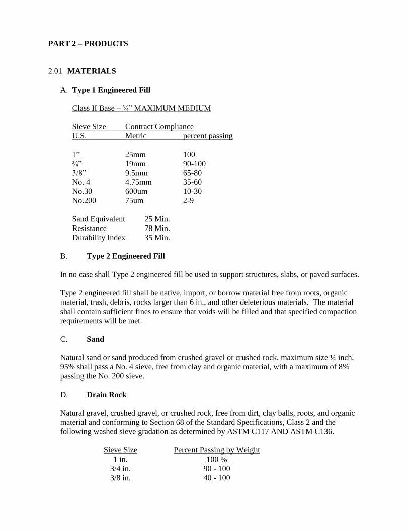
PART 2 – PRODUCTS
2.01 MATERIALS
A. Type 1 Engineered Fill
Class II Base – ¾” MAXIMUM MEDIUM
Sieve Size Contract Compliance
U.S. Metric percent passing
1” 25mm 100
¾” 19mm 90-100
3/8” 9.5mm 65-80
No. 4 4.75mm 35-60
No.30 600um 10-30
No.200 75um 2-9
Sand Equivalent 25 Min.
Resistance 78 Min.
Durability Index 35 Min.
B. Type 2 Engineered Fill
In no case shall Type 2 engineered fill be used to support structures, slabs, or paved surfaces.
Type 2 engineered fill shall be native, import, or borrow material free from roots, organic
material, trash, debris, rocks larger than 6 in., and other deleterious materials. The material
shall contain sufficient fines to ensure that voids will be filled and that specified compaction
requirements will be met.
C. Sand
Natural sand or sand produced from crushed gravel or crushed rock, maximum size ¼ inch,
95% shall pass a No. 4 sieve, free from clay and organic material, with a maximum of 8%
passing the No. 200 sieve.
D. Drain Rock
Natural gravel, crushed gravel, or crushed rock, free from dirt, clay balls, roots, and organic
material and conforming to Section 68 of the Standard Specifications, Class 2 and the
following washed sieve gradation as determined by ASTM C117 AND ASTM C136.
Sieve Size Percent Passing by Weight
1 in. 100 %
3/4 in. 90 - 100
3/8 in. 40 - 100
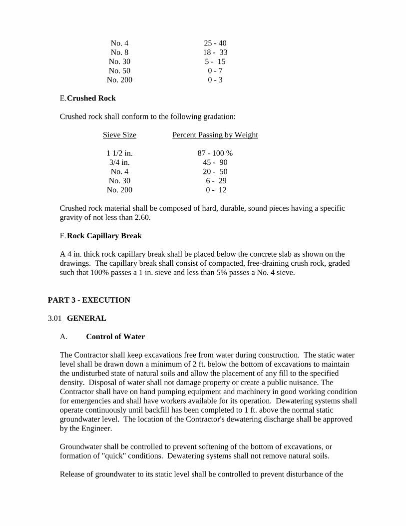
No. 4 25 - 40
No. 8 18 - 33
No. 30 5 - 15
No. 50 0 - 7
No. 200 0 - 3
E. Crushed Rock
Crushed rock shall conform to the following gradation:
Sieve Size Percent Passing by Weight
1 1/2 in. 87 - 100 %
3/4 in. 45 - 90
No. 4 20 - 50
No. 30 6 - 29
No. 200 0 - 12
Crushed rock material shall be composed of hard, durable, sound pieces having a specific
gravity of not less than 2.60.
F. Rock Capillary Break
A 4 in. thick rock capillary break shall be placed below the concrete slab as shown on the
drawings. The capillary break shall consist of compacted, free-draining crush rock, graded
such that 100% passes a 1 in. sieve and less than 5% passes a No. 4 sieve.
PART 3 - EXECUTION
3.01 GENERAL
A. Control of Water
The Contractor shall keep excavations free from water during construction. The static water
level shall be drawn down a minimum of 2 ft. below the bottom of excavations to maintain
the undisturbed state of natural soils and allow the placement of any fill to the specified
density. Disposal of water shall not damage property or create a public nuisance. The
Contractor shall have on hand pumping equipment and machinery in good working condition
for emergencies and shall have workers available for its operation. Dewatering systems shall
operate continuously until backfill has been completed to 1 ft. above the normal static
groundwater level. The location of the Contractor's dewatering discharge shall be approved
by the Engineer.
Groundwater shall be controlled to prevent softening of the bottom of excavations, or
formation of "quick" conditions. Dewatering systems shall not remove natural soils.
Release of groundwater to its static level shall be controlled to prevent disturbance of the
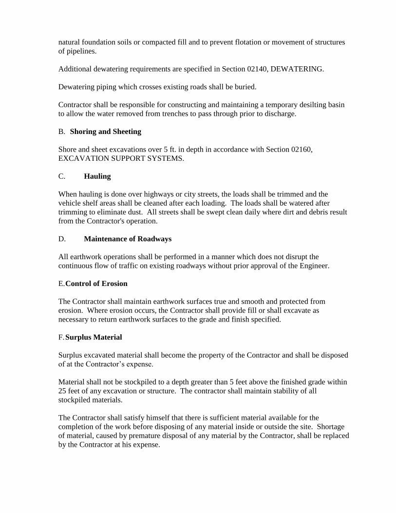
natural foundation soils or compacted fill and to prevent flotation or movement of structures
of pipelines.
Additional dewatering requirements are specified in Section 02140, DEWATERING.
Dewatering piping which crosses existing roads shall be buried.
Contractor shall be responsible for constructing and maintaining a temporary desilting basin
to allow the water removed from trenches to pass through prior to discharge.
B. Shoring and Sheeting
Shore and sheet excavations over 5 ft. in depth in accordance with Section 02160,
EXCAVATION SUPPORT SYSTEMS.
C. Hauling
When hauling is done over highways or city streets, the loads shall be trimmed and the
vehicle shelf areas shall be cleaned after each loading. The loads shall be watered after
trimming to eliminate dust. All streets shall be swept clean daily where dirt and debris result
from the Contractor's operation.
D. Maintenance of Roadways
All earthwork operations shall be performed in a manner which does not disrupt the
continuous flow of traffic on existing roadways without prior approval of the Engineer.
E. Control of Erosion
The Contractor shall maintain earthwork surfaces true and smooth and protected from
erosion. Where erosion occurs, the Contractor shall provide fill or shall excavate as
necessary to return earthwork surfaces to the grade and finish specified.
F. Surplus Material
Surplus excavated material shall become the property of the Contractor and shall be disposed
of at the Contractor’s expense.
Material shall not be stockpiled to a depth greater than 5 feet above the finished grade within
25 feet of any excavation or structure. The contractor shall maintain stability of all
stockpiled materials.
The Contractor shall satisfy himself that there is sufficient material available for the
completion of the work before disposing of any material inside or outside the site. Shortage
of material, caused by premature disposal of any material by the Contractor, shall be replaced
by the Contractor at his expense.
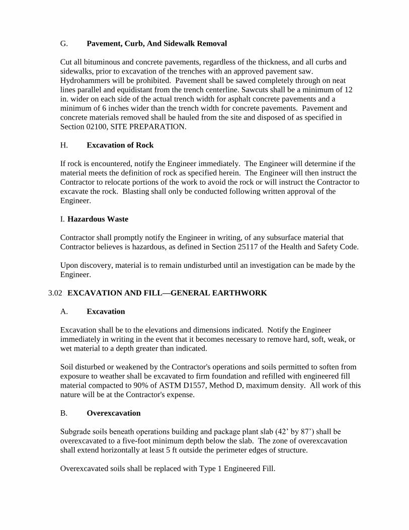
G. Pavement, Curb, And Sidewalk Removal
Cut all bituminous and concrete pavements, regardless of the thickness, and all curbs and
sidewalks, prior to excavation of the trenches with an approved pavement saw.
Hydrohammers will be prohibited. Pavement shall be sawed completely through on neat
lines parallel and equidistant from the trench centerline. Sawcuts shall be a minimum of 12
in. wider on each side of the actual trench width for asphalt concrete pavements and a
minimum of 6 inches wider than the trench width for concrete pavements. Pavement and
concrete materials removed shall be hauled from the site and disposed of as specified in
Section 02100, SITE PREPARATION.
H. Excavation of Rock
If rock is encountered, notify the Engineer immediately. The Engineer will determine if the
material meets the definition of rock as specified herein. The Engineer will then instruct the
Contractor to relocate portions of the work to avoid the rock or will instruct the Contractor to
excavate the rock. Blasting shall only be conducted following written approval of the
Engineer.
I. Hazardous Waste
Contractor shall promptly notify the Engineer in writing, of any subsurface material that
Contractor believes is hazardous, as defined in Section 25117 of the Health and Safety Code.
Upon discovery, material is to remain undisturbed until an investigation can be made by the
Engineer.
3.02 EXCAVATION AND FILL—GENERAL EARTHWORK
A. Excavation
Excavation shall be to the elevations and dimensions indicated. Notify the Engineer
immediately in writing in the event that it becomes necessary to remove hard, soft, weak, or
wet material to a depth greater than indicated.
Soil disturbed or weakened by the Contractor's operations and soils permitted to soften from
exposure to weather shall be excavated to firm foundation and refilled with engineered fill
material compacted to 90% of ASTM D1557, Method D, maximum density. All work of this
nature will be at the Contractor's expense.
B. Overexcavation
Subgrade soils beneath operations building and package plant slab (42’ by 87’) shall be
overexcavated to a five-foot minimum depth below the slab. The zone of overexcavation
shall extend horizontally at least 5 ft outside the perimeter edges of structure.
Overexcavated soils shall be replaced with Type 1 Engineered Fill.
C. Filling Operations
1. Subgrade for Engineered Fill
All areas to receive engineered fill shall be prepared as specified herein.
For subgrades composed of undisturbed bedrock which is also classified as competent
material, the subgrade shall be left undisturbed.
For subgrades not composed of competent bedrock the surface to receive engineered fill
shall be scarified to a depth of 24 in., moisture conditioned, and compacted in 8 inch
lifts as specified in Section 3.05.
2. Proof-Rolling
Unless otherwise directed in writing by the Engineer proof-roll all subgrade surfaces,
except undisturbed bedrock, prior to constructing engineered fill. Use a half loaded
dump truck or similar heavy-wheeled vehicle acceptable to the Engineer to detect soft or
loose zones. Notify the Engineer prior to commencement of proof-rolling. If soft or
loose zones are found, excavate the soft or loose material to a depth directed by the
Engineer, then fill and compact as specified for engineered fill. The quantity and
placement of such material will be paid for as extra work.
3. Construction of Engineered Fill
Construct engineered fill to lines and cross sections shown. Deposit fill material in lifts
not exceeding 8 inches in loose depth, moisture condition, and compact as specified in
Section 3.05.
No fill shall be placed during weather conditions which will alter the moisture content
of the fill materials sufficiently to make adequate compaction impossible. After placing
operations have been stopped because of adverse weather conditions, no additional fill
material shall be placed until the last layer compacted has been checked and found to be
compacted to the specified densities.
Care should be taken during fill placement to prevent and/or correct any unstable or
"pumping" subgrade conditions. Such conditions could develop with a combination of
factors, including overly moist soils, heavy construction, equipment or frequent
movement of equipment. If an unstable or "pumping" condition should develop as
determined by the Engineer, the affected soils shall be removed and replaced or aerated
and allowed to stabilize prior to further work in the area. Furthermore, when, in the
judgment of the Engineer, sufficient compaction effort has not been used or where the
field density tests indicate that the required compaction or moisture content has not been
obtained, the fill shall be reworked and recompacted as needed to obtain a stable fill at
the required density and moisture content prior to placing additional fill materials.
The Contractor shall be responsible for the maintenance and protection of all
embankments and fills made during the contract period and shall bear the expense of
replacing any portion which has been displaced due to carelessness, negligent work,
erosion or failure to take proper precautions.
3.03 EXCAVATION AND BACKFILL – PIPELINES AND UTILITIES
A. Excavation
1. General
Pipelines and utilities shall be installed in trenches. Excavation shall include the
satisfactory loosening, removing, loading, stockpiling, transporting, and
placement in final location (including disposal) of all materials necessary to for
construction of trenches. Trench excavation shall include the removal of all
materials and/or obstructions of any nature.
2. Trenching
Minimum trench width for piping shall be the outside diameter of the piping plus
18 inches. For duct banks the minimum width shall be three inches wider than the
outside edges of the conduit bank. Maximum trench widths at the top of the pipe
shall be as shown on the Drawings for the designated type bedding. For drainage
pipe, if no maximum is shown, the Contractor shall limit top trench widths to pipe
outside diameter plus 24 inches for pipe 24 inches or smaller, and pipe outside
diameter plus 36 inches for pipe 27 inches and larger, except upon written
approval of a wider trench by the Engineer.
If, because of soil conditions, safety requirements or other reasons, the trench
width at top of pipe is increased beyond the width specified in the preceding
paragraphs, laying conditions shall be upgraded or stronger pipe installed,
designed in conformance with the specifications for the increased trench width,
without additional cost to the Owner.
3. Manholes, Valves And Appurtenances
Excavation for manholes, valves, or other accessories shall be sufficient to leave
at least 12 inches in the clear between their outer surfaces and the trench side,
trench shield or shoring. Backfill under manholes, vaults, tanks, or valves shall
be imported material as designated on the drawings. Any unauthorized excess
excavation below the elevation indicated for foundation of any structure shall be
filled with sand, base material, or concrete, at the direction of the Engineer, and at
the expense of the Contractor. Backfilling of manhole excavation shall conform
to the backfilling required for trenches.
4. Location Of Excavated Materials
During trench excavation, place the excavated material only within the approved
working area. Do not obstruct any roadways or streets unless specified otherwise.
Conform to all Federal, State, and local codes governing the safe loading of all
trenches with excavated material.
Material shall not be stockpiled greater than 5 feet above grade within 25 feet of
any excavation.
5. Overexcavation
Where the undisturbed condition of natural soils is inadequate for support of the
planned construction, the Engineer will direct the Contractor to overexcavate to
adequate supporting soils. The excavated space shall be filled to the specified
elevation with bedding. The quantity and placement of such material will be paid
for as follows:
1. Overexcavation and refilling up to 12 inches below the specified trench
bottom elevation shall be solely the Contractor's responsibility and expense.
2. Overexcavation and refilling in excess of 12 inches below the specified trench
bottom elevation will be considered extra work.
B. Backfill
1. General
Construct backfill as indicated and specified in this section. Place backfill in 8 in.
maximum loose lifts unless otherwise specified. Bring up evenly on each side
and along the full length of the pipe. Ensure that no damage is done to structures,
pipe or their protective coatings. Compact each loose lift as specified in
Subsection 3.05, Compaction, before placing the next lift. Do not backfill in
freezing weather or where the material in the trench is already frozen or is muddy,
except as authorized.
Where settlements occur in trenches due to improper compaction, the Contractor
shall excavate to the depth necessary to rectify the problem, then backfill,
compact as specified herein, and restore the surface to the required elevation. If
pavement is damaged, it shall be removed after carefully sawcutting the damaged
area, and replaced as originally specified. All costs of repairing settlement and
related damage shall be borne by the Contractor.
2. Bedding and Initial Backfill
The pipe shall be placed on a bed of imported materials. All loose material shall
be removed from the trench bottom before placing the bedding material. Bedding
shall extend at least 4 inches below the pipe barrel (6 inches for a pipe greater
than 6 inches in diameter) and 1-1/2 inches below the pipe joint bell. No wedging
or blocking of the pipe will be permitted. The pipe shall be bedded uniformly
throughout its length. The bearing shall be achieved by shaping the bedding or by
lightly "bouncing" the pipe to set it into the bedding.
The Contractor shall then place initial backfill material. Each lift shall be worked
under the haunches of the pipe and thoroughly compacted to the specified
compaction by shovel slicing, tamping and other appropriate means to achieve a
dense and thoroughly compacted material that provides proper support under the
pipe haunches. Care shall be used not to disturb or displace the pipe. Initial
backfill shall be the material placed from the top of the bedding to a point 12
inches above the top of the pipe and pipe bell. Initial backfill shall be carefully
placed evenly on both sides of the pipe so as not to disturb or damage the pipe,
and compacted to the specified compaction. Jetting will not be allowed.
3. Subsequent Backfill
Subsequent trench backfill above the initial backfill shall be placed and
compacted as specified. Jetting will not be allowed. However, until the total
backfill above the top of the pipe exceeds 3 feet, machine-placed backfill material
shall not be allowed to "free-fall" more than 2 feet. If the excavation is through
an area used for horticulture, lawns or other cultivated areas, the final 12 inches of
backfill shall be essentially the original topsoil which shall have been removed
and stockpiled separately.
4. Finish Grading
Finished surfaces shall be smooth, compacted and free from irregularities. The
degree of finish shall be that normally obtainable with a blade-grader.
Finished grade shall be as specified by the contours plus or minus 0.10 feet except
where a local change in elevation is required to match sidewalks, curbs, manholes
and catch basins, or to ensure proper drainage. Allowance for topsoil and grass
cover, and subbase and pavement thickness shall be made.
5. Buried Warning and Identification Tape
Install tape specified in Section 15060, PIPING SYSTEMS, above all buried
pipes and conduits in accordance with manufacturer's recommendations except as
modified herein. Bury tape 12 inches below finished grade; under pavements and
slabs, bury tape 6 inches below top of subgrade.
6. Open Trench
The Contractor shall not leave trenches open during hours when the Contractor is
not actively working. All trenches shall be backfilled at the end of the day or up
to 200 feet may be left shored and plated.
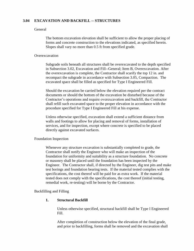
3.04 EXCAVATION AND BACKFILL -- STRUCTURES
General
The bottom excavation elevation shall be sufficient to allow the proper placing of
forms and concrete construction to the elevations indicated, as specified herein.
Slopes shall vary no more than 0.5 ft from specified grade.
Overexcavation
Subgrade soils beneath all structures shall be overexcavated to the depth specified
in Subsection 3.02, Excavation and Fill--General; Item B, Overexcavation. After
the overexcavation is complete, the Contractor shall scarify the top 12 in. and
recompact the subgrade in accordance with Subsection 3.05, Compaction. The
excavated space shall be filled as specified for Type I Engineered Fill.
Should the excavation be carried below the elevation required per the contract
documents or should the bottom of the excavation be disturbed because of the
Contractor’s operations and require overexcavation and backfill, the Contractor
shall refill such excavated space to the proper elevation in accordance with the
procedure specified for Type I Engineered Fill at his expense.
Unless otherwise specified, excavation shall extend a sufficient distance from
walls and footings to allow for placing and removal of forms, installation of
services, and for inspection, except where concrete is specified to be placed
directly against excavated surfaces.
Foundation Inspection
Whenever any structure excavation is substantially completed to grade, the
Contractor shall notify the Engineer who will make an inspection of the
foundation for uniformity and suitability as a structure foundation. No concrete
or masonry shall be placed until the foundation has been inspected by the
Engineer. The Contractor shall, if directed by the Engineer, dig test pits and make
test borings and foundation bearing tests. If the material tested complies with the
specifications, the cost thereof will be paid for as extra work. If the material
tested does not comply with the specifications, the cost thereof (initial testing,
remedial work, re-testing) will be borne by the Contractor.
Backfilling and Filling
1. Structural Backfill
Unless otherwise specified, structural backfill shall be Type I Engineered
Fill.
After completion of construction below the elevation of the final grade,
and prior to backfilling, forms shall be removed and the excavation shall
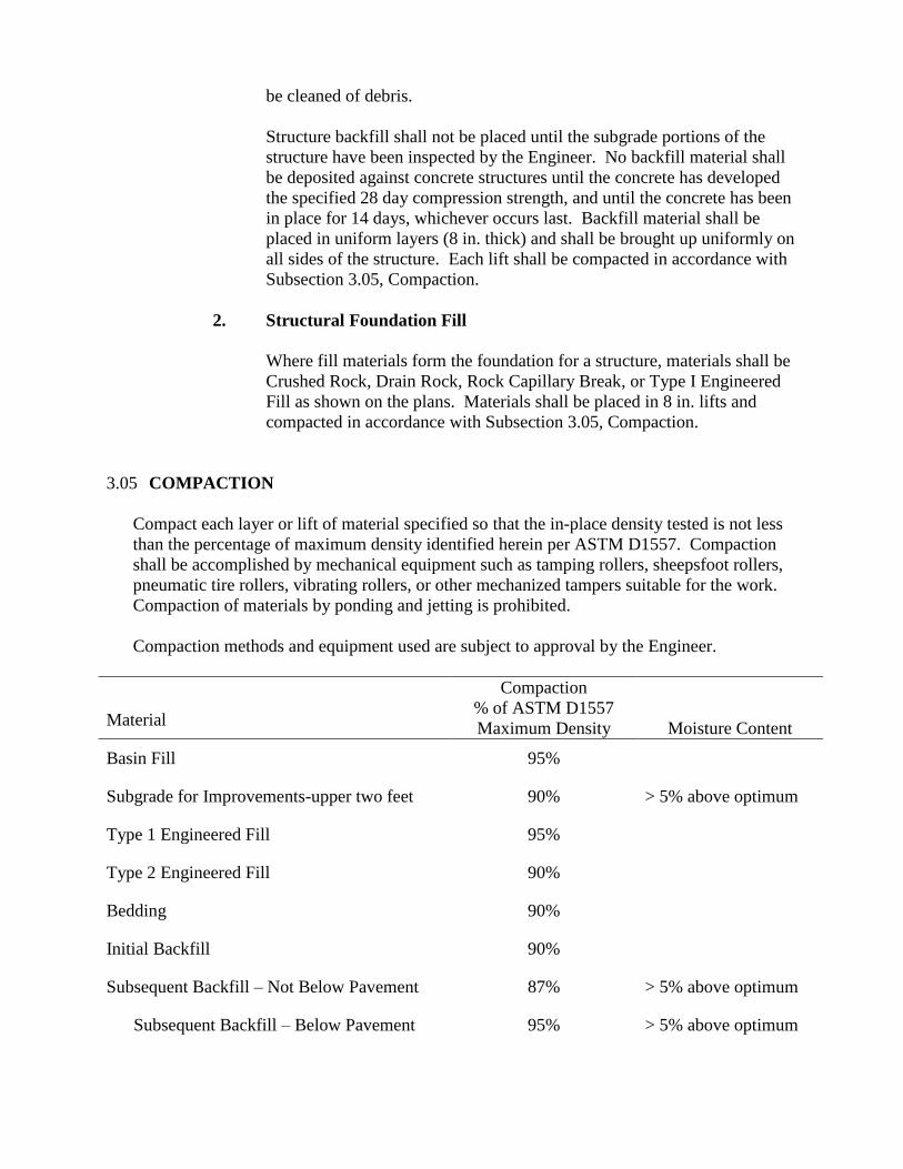
be cleaned of debris.
Structure backfill shall not be placed until the subgrade portions of the
structure have been inspected by the Engineer. No backfill material shall
be deposited against concrete structures until the concrete has developed
the specified 28 day compression strength, and until the concrete has been
in place for 14 days, whichever occurs last. Backfill material shall be
placed in uniform layers (8 in. thick) and shall be brought up uniformly on
all sides of the structure. Each lift shall be compacted in accordance with
Subsection 3.05, Compaction.
2. Structural Foundation Fill
Where fill materials form the foundation for a structure, materials shall be
Crushed Rock, Drain Rock, Rock Capillary Break, or Type I Engineered
Fill as shown on the plans. Materials shall be placed in 8 in. lifts and
compacted in accordance with Subsection 3.05, Compaction.
3.05 COMPACTION
Compact each layer or lift of material specified so that the in-place density tested is not less
than the percentage of maximum density identified herein per ASTM D1557. Compaction
shall be accomplished by mechanical equipment such as tamping rollers, sheepsfoot rollers,
pneumatic tire rollers, vibrating rollers, or other mechanized tampers suitable for the work.
Compaction of materials by ponding and jetting is prohibited.
Compaction methods and equipment used are subject to approval by the Engineer.
Material
Compaction
% of ASTM D1557
Maximum Density
Moisture Content
Basin Fill 95%
Subgrade for Improvements-upper two feet 90% > 5% above optimum
Type 1 Engineered Fill 95%
Type 2 Engineered Fill 90%
Bedding 90%
Initial Backfill 90%
Subsequent Backfill – Not Below Pavement 87% > 5% above optimum
Subsequent Backfill – Below Pavement 95% > 5% above optimum
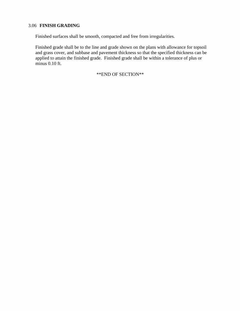
3.06 FINISH GRADING
Finished surfaces shall be smooth, compacted and free from irregularities.
Finished grade shall be to the line and grade shown on the plans with allowance for topsoil
and grass cover, and subbase and pavement thickness so that the specified thickness can be
applied to attain the finished grade. Finished grade shall be within a tolerance of plus or
minus 0.10 ft.
**END OF SECTION**
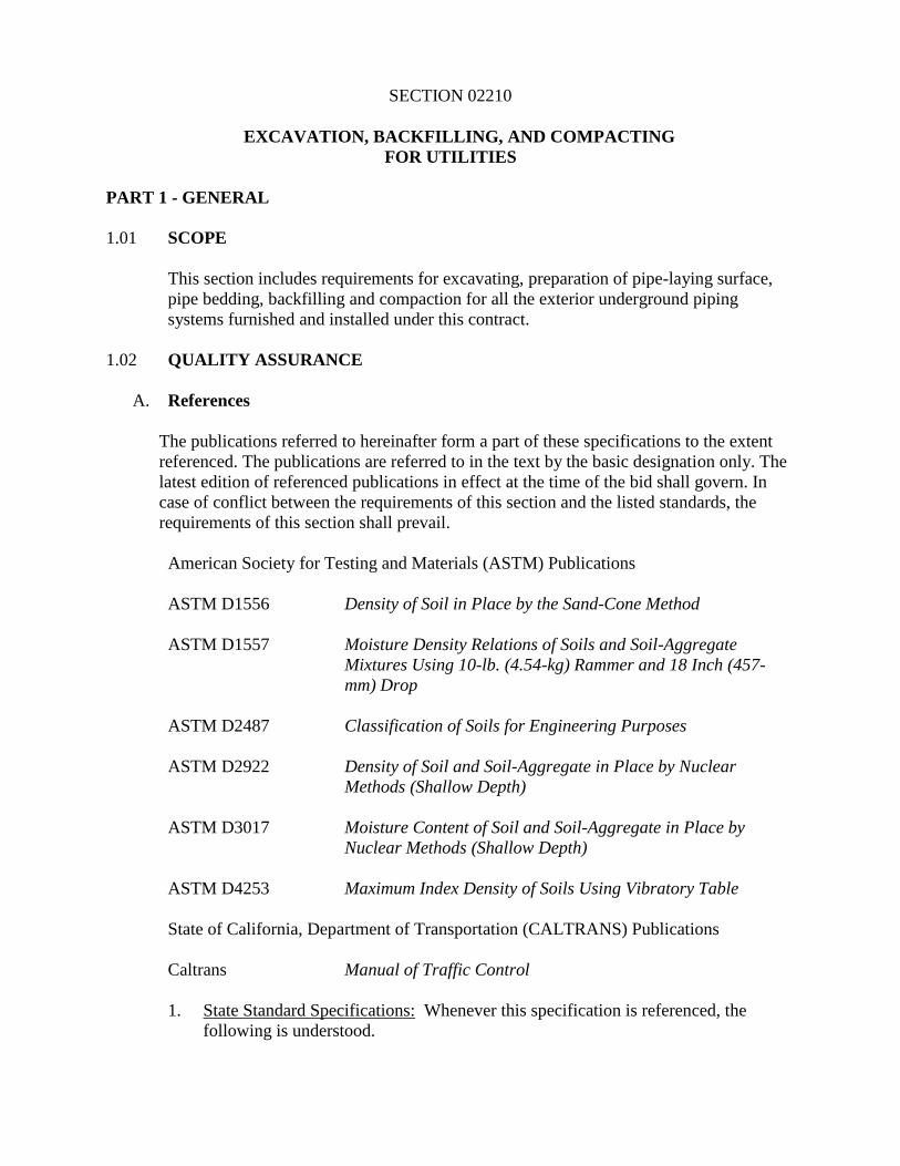
SECTION 02210
EXCAVATION, BACKFILLING, AND COMPACTING
FOR UTILITIES
PART 1 - GENERAL
1.01 SCOPE
This section includes requirements for excavating, preparation of pipe-laying surface,
pipe bedding, backfilling and compaction for all the exterior underground piping
systems furnished and installed under this contract.
1.02 QUALITY ASSURANCE
A. References
The publications referred to hereinafter form a part of these specifications to the extent
referenced. The publications are referred to in the text by the basic designation only. The
latest edition of referenced publications in effect at the time of the bid shall govern. In
case of conflict between the requirements of this section and the listed standards, the
requirements of this section shall prevail.
American Society for Testing and Materials (ASTM) Publications
ASTM D1556 Density of Soil in Place by the Sand-Cone Method
ASTM D1557 Moisture Density Relations of Soils and Soil-Aggregate
Mixtures Using 10-lb. (4.54-kg) Rammer and 18 Inch (457-
mm) Drop
ASTM D2487 Classification of Soils for Engineering Purposes
ASTM D2922 Density of Soil and Soil-Aggregate in Place by Nuclear
Methods (Shallow Depth)
ASTM D3017 Moisture Content of Soil and Soil-Aggregate in Place by
Nuclear Methods (Shallow Depth)
ASTM D4253 Maximum Index Density of Soils Using Vibratory Table
State of California, Department of Transportation (CALTRANS) Publications
Caltrans Manual of Traffic Control
1. State Standard Specifications: Whenever this specification is referenced, the
following is understood.
a. All references to statistical testing are deleted.
b. Whenever a discrepancy occurs between the Standard Specifications and this
specification, it is understood that this specification governs.
c. All references to measurement and payment are deleted.
B. Tests
The Engineer will take samples and perform moisture content, compaction, and density
tests during placement of backfill materials to check compliance with these
specifications. The Contractor shall remove surface material at locations designated by
the Engineer and provide such assistance as necessary for sampling and testing. The
Engineer may direct the Contractor to construct inspection trenches in compacted or
consolidated backfill to determine that the Contractor has complied with these
specifications.
Tests will be made by the Engineer in accordance with the following:
Moisture content ASTM D3017
Density in-place ASTM D1556 or ASTM D2922
Moisture-density relationships ASTM D1557
1.03 SUBMITTALS
The Contractor shall submit information in accordance with Section 01300,
SUBMITTALS, to substantiate compliance with this specification.
1.04 DEFINITIONS
A. Backfill
Material used in refilling a trench or other excavation above the pipe or utility.
B. Compaction
The process of mechanically stabilizing a material by increasing its density at a
controlled moisture condition. "Degree of Compaction" is expressed as a percentage of
the maximum density obtained by the test procedure described in ASTM D1557 for
general soil types abbreviated in this specification as "XX% ASTM D1557 maximum
density" or “XX% compaction.”
C. Granular Pipe Bedding
A dense, well-graded aggregate mixture of sand, gravel, or crushed stone (mixed
individually, in combination with each other, or with on-site soil as specified) placed on
a subgrade below the pipe to provide a suitable foundation for pipe.
D. Unyielding Material
Rock, rib, ridge, rock protrusion, or solid with cobbles in the trench bottom requiring a
covering of finer grain material or special bedding to avoid bridging in the pipe or
conduit.
E. Material
Material in the trench bottom which lacks firmness to maintain alignment and prevent
joints from separating in the pipe, conduit, or appurtenant structure during backfilling.
This may be material otherwise identified as satisfactory which has been disturbed or
saturated.
F. Lift
A layer or course of soil placed on top of unprepared subgrade or a previously prepared
or placed soil in a fill or backfill.
G. Rock
Rock is defined as any material which cannot be excavated with a track mounted 235
Caterpillar backhoe with a narrow bucket, and teeth, and requires the use of special
buckets, rock teeth, jack-hammering, blasting and/or other special methods of
excavation. The Construction Manager will make the determination as to whether
material is classified as rock.
H. Unsatisfactory Material
Existing in-place soil, unstable material, substandard fill material or other material
designated by the Construction Manager as having insufficient strength or stability to
carry intended loads without excessive consolidation or loss of stability. Also backfill
material which contains refuse, frozen material, large rocks, debris and other material
which could damage the pipe or cause the backfill not to compact. As a minimum,
materials classified as PT, OH, or OL by ASTM D2487 are unsatisfactory.
I. Initial Backfill
Backfill from the bottom of the pipe to 12 in. above the top of the pipe.
J. Subsequent Backfill
Backfill from 12 in. above the pipe to the top of the trench or subgrade surface for
paving materials.
K. Optimum Moisture Content
Optimum moisture content shall be determined in accordance with ASTM D1557.
L. Excavation
The removal of soil to obtain in specified depth or elevation.
M. Subgrade
The uppermost layer of material (sometimes in situ soil or rock) graded or otherwise
prepared for supporting the addition of base material, fill material, or structural
foundation materials.
PART 2 - PRODUCTS
2.01 MATERIALS
A. Bedding Material
Bedding material shall be a select granular material free from organic matter and of such
size and gradation that the specified compaction can be readily attained. As a minimum,
materials shall have a sand equivalent value of not less than 30 (California Test Method
217) and shall conform to the following gradation:
U.S. standard Percent by
sieve size weight passing
3/4 inch 100
No. 4 35-100
No. 30 20-100
B. Initial Backfill
Initial backfill shall conform to specifications for bedding material for this contract.
C. Subsequent Backfill Material
1. Outside Paved Areas: Backfill material shall be select native or import material,
free from organic or other deleterious material, and any material over 3 inches in
any dimension.
2. Inside Paved Areas: Backfill material shall be Class 2 aggregate base material
conforming to Section 26 of the State Standard Specifications. Aggregate shall
conform to grading requirements for 3/4 inch maximum grading.
D. Buried Warning and Identification Tape
Polyethylene plastic and metallic core or metallic-faced, acid-and alkali-resistant,
polyethylene plastic warning tape shall be manufactured specifically for warning and
identification of buried utility lines. Provide tape on rolls, 3 in. minimum width, color
coded for the intended utility with a warning and identification imprinted in bold black
letters continuously over the entire tape length. Warning and identification to read,
"CAUTION, BURIED (intended service) LINE BELOW" or similar wording. Color and
printing is to be permanent, unaffected by moisture or soil.
1. Warning Tape for Metallic Piping: Acid and alkali-resistant polyethylene plastic
tape conforming to the width, color, and printing requirements indicated above.
Minimum thickness of the tape shall be 0.003 in. Tape shall have a minimum
strength of 1,500 psi lengthwise and 1,250 psi crosswise with a maximum 350%
elongation.
2. Detectable Warning Tape for Non-Metallic Piping: Polyethylene plastic tape
conforming to the width, color, and printing requirements indicated above.
Minimum thickness of the tape shall be 0.004 in. Tape shall have a minimum
strength of 1,500 psi lengthwise and 1,250 psi crosswise. The tape shall be
manufactured with integral wires, foil backing, or other means of enabling
detection by a metal detector when the tape is buried up to 3 ft deep. Encase the
metallic element of the tape in a protective jacket or provide with other means of
corrosion protection.
PART 3 - EXECUTION
3.01 GENERAL
A. Control of Water
The Contractor shall keep excavations free from water during construction. The static
water level shall be drawn down a minimum of 2 ft below the bottom of excavations to
maintain the undisturbed state of natural soils and allow the placement of any fill to the
specified density. Disposal of water shall not damage property or create a public
nuisance. The Contractor shall have on hand pumping equipment and machinery in
good working condition for emergencies and shall have workers available for its
operation. Dewatering systems shall operate continuously until backfill has been
completed to 1 ft above the normal static groundwater level. The location of the
Contractor's dewatering discharge shall be approved by the Engineer.
Groundwater shall be controlled to prevent softening of the bottom of excavations, or
formation of "quick" conditions. Dewatering systems shall not remove natural soils.
Release of groundwater to its static level shall be controlled to prevent disturbance of
the natural foundation soils or compacted fill and to prevent flotation or movement of
structures of pipelines.
Additional dewatering requirements are specified in Section 02140, DEWATERING.
Dewatering piping which crosses existing roads shall be buried.
Contractor shall be responsible for constructing and maintaining a temporary desilting
basin to allow the water removed from trenches to pass through prior to discharge.
B. Shoring and Sheeting
Shore and sheet excavations over 5 ft in depth in accordance with Section 02160,
EXCAVATION SUPPORT SYSTEMS.
3.02 EXCAVATION
A. General
Pipelines and utilities shall be installed in trenches. Excavation shall include the
satisfactory loosening, removing, loading, stockpiling, transporting, and placement in
final location (including disposal) of all materials necessary to for construction of
trenches. Trench excavation shall include the removal of all materials and/or obstructions
of any nature.
B. Trenching
Minimum trench width for piping shall be the outside diameter of the piping plus 18
inches. For duct banks the minimum width shall be three inches wider than the outside
edges of the conduit bank. Maximum trench widths at the top of the pipe shall be as
shown on the Drawings for the designated type bedding. For drainage pipe, if no
maximum is shown, the Contractor shall limit top trench widths to pipe outside diameter
plus 24 inches for pipe 24 inches or smaller, and pipe outside diameter plus 36 inches for
pipe 27 inches and larger, except upon written approval of a wider trench by the
Engineer.
If, because of soil conditions, safety requirements or other reasons, the trench width at
top of pipe is increased beyond the width specified in the preceding paragraphs, laying
conditions shall be upgraded or stronger pipe installed, designed in conformance with the
specifications for the increased trench width, without additional cost to the City.
C. Manholes, Valves and Appurtenances
Excavation for manholes, valves, or other accessories shall be sufficient to leave at least
12 inches in the clear between their outer surfaces and the trench side, trench shield or
shoring. Backfill under manholes, vaults, tanks, or valves shall be imported material as
designated on the drawings. Any unauthorized excess excavation below the elevation
indicated for foundation of any structure shall be filled with imported materials or
concrete, at the direction of the Engineer, and at the expense of the Contractor.
Backfilling of manhole excavation shall conform to the backfilling required for trenches.
D. Location of Excavated Materials
During trench excavation, place the excavated material only within the approved working
area. Do not obstruct any roadways or streets unless specified otherwise. Conform to all
Federal, State, and local codes governing the safe loading of all trenches with excavated
material.
Material shall not be stockpiled greater than 5 feet above grade within 25 feet of any
excavation.
E. Overexcavation
Where the undisturbed condition of natural soils is inadequate for support of the planned
construction, the Engineer will direct the Contractor to overexcavate to adequate
supporting soils. The excavated space shall be filled to the specified elevation with
bedding. The quantity and placement of such material will be paid for as follows:
1. Overexcavation and refilling up to 12 inches below the specified trench bottom
elevation shall be solely the Contractor's responsibility and expense.
2. Overexcavation and refilling in excess of 12 inches below the specified trench bottom
elevation will be considered extra work.
F. Surplus Material
Surplus excavated material shall become the property of the Contractor and shall be
disposed of at the Contractor’s expense.
The Contractor shall satisfy himself that there is sufficient material available for the
completion of the work before disposing of any material inside or outside the site.
Shortage of material, caused by premature disposal of any material by the Contractor,
shall be replaced by the Contractor at his expense.
G. Pavement, Curb, And Sidewalk Removal
Cut all bituminous and concrete pavements, regardless of the thickness, and all curbs and
sidewalks, prior to excavation of the trenches with an approved pavement saw.
Hydrohammers will be prohibited. Pavement shall be sawed completely through on neat
lines parallel and equidistant from the trench centerline. Sawcuts shall be a minimum of
12 in. wider on each side of the actual trench width for asphalt concrete pavements and a
minimum of 6 inches wider than the trench width for concrete pavements. Pavement and
concrete materials removed shall be hauled from the site and disposed of as specified in
Section 02100, SITE PREPARATION.
3.03 BACKFILL
A. General
Construct backfill as indicated and specified in this section. Place backfill in 8 in.
maximum loose lifts unless otherwise specified. Bring up evenly on each side and along
the full length of the pipe. Ensure that no damage is done to structures, pipe or their
protective coatings. Compact each loose lift as specified below before placing the next
lift. Do not backfill in freezing weather or where the material in the trench is already
frozen or is muddy, except as authorized.
Where settlements occur in trenches due to improper compaction, the Contractor shall
excavate to the depth necessary to rectify the problem, then backfill, compact as specified
herein, and restore the surface to the required elevation. If pavement is damaged, it shall
be removed after carefully sawcutting the damaged area, and replaced as originally
specified. All costs of repairing settlement and related damage shall be borne by the
Contractor.
B. Bedding and Initial Backfill
The pipe shall be placed on a bed of imported materials. All loose material shall be
removed from the trench bottom before placing the bedding material. Bedding shall
extend at least 4 inches below the pipe barrel (6 inches for a pipe greater than 6 inches in
diameter) and 1-1/2 inches below the pipe joint bell. No wedging or blocking of the pipe
will be permitted. The pipe shall be bedded uniformly throughout its length. The bearing
shall be achieved by shaping the bedding or by lightly "bouncing" the pipe to set it into
the bedding.
The Contractor shall then place initial backfill material. Each lift shall be worked under
the haunches of the pipe and thoroughly compacted to the specified compaction by
shovel slicing, tamping and other appropriate means to achieve a dense and thoroughly
compacted material that provides proper support under the pipe haunches. Care shall be
used not to disturb or displace the pipe. Initial backfill shall be the material placed from
the top of the bedding to a point 12 inches above the top of the pipe and pipe bell. Initial
backfill shall be carefully placed evenly on both sides of the pipe so as not to disturb or
damage the pipe, and compacted to the specified compaction. Jetting will not be allowed.
C. Subsequent Backfill
Subsequent trench backfill above the initial backfill shall be placed and compacted as
specified. Jetting will not be allowed. However, until the total backfill above the top of
the pipe exceeds 3 feet, machine-placed backfill material shall not be allowed to "free-
fall" more than 2 feet. If the excavation is through an area used for horticulture, lawns or
other cultivated areas, the final 12 inches of backfill shall be essentially the original
topsoil which shall have been removed and stockpiled separately.
D. Finish Grading
Finished surfaces shall be smooth, compacted and free from irregularities. The degree of
finish shall be that normally obtainable with a blade-grader.
Finished grade shall be as specified by the contours plus or minus 0.10 feet except where
a local change in elevation is required to match sidewalks, curbs, manholes and catch
basins, or to ensure proper drainage. Allowance for topsoil and grass cover, and subbase
and pavement thickness shall be made.
E. Buried Warning and Identification Tape
Install tape above all buried pipes and conduits in accordance with manufacturer's
recommendations except as modified herein. Bury tape 12 inches below finished grade;
under pavements and slabs, bury tape 6 inches below top of subgrade.
F. Open Trench
The Contractor shall not leave trenches open during hours when the Contractor is not
actively working. All trenches shall be backfilled at the end of the day or up to 200 feet
may be left shored and plated.
3.04 COMPACTION
A. General
Compact each layer of lift of material so that the in-place density tested is not less than
the percentage of maximum density identified below, except where specified otherwise
on the drawings. Use hand-operated, plate-type, vibratory, or other suitable hand tampers
in areas not accessible to larger rollers or compactors. Avoid damaging pipes and
protective pipe coatings. Compaction of materials by ponding and jetting is prohibited
unless specifically pre-approved by the Engineer.
Material
Compaction
% of ASTM D1557
Maximum Density
Bedding 90%
Initial Backfill 90%
Subsequent Backfill – Not Below Pavement 90%
Subsequent Backfill – Below Pavement 95%
3.05 VEHICULAR ACCESS
1. Barricades, traffic control signs, cones and flagmen shall be provided to re-route
traffic and to protect all open trenches, materials, and equipment. Barricades and
signs shall be marked by low-intensity flasher lights for night traffic. Traffic control
shall be in strict accordance with the State of California, Business and Transportation
Agency, Department of Transportation (CALTRANS) Manual of Traffic Control.
2. All trenching, pipe installation, and backfilling in vehicular traveled areas shall be
conducted in a manner to cause the least interruptions possible to vehicular access.
The Contractor shall remove all surplus material away from the jobsite as it is
produced. Backfilling and paving operations shall progress as fast as trenching and
pipe installation will permit.
3. Where excavated lines cross streets, all lanes shall be opened to traffic immediately
after the pipe has been installed in the trench. Construction time in these areas shall
be kept to a minimum. Steel plate coverings shall be placed over the trench to permit
passage of vehicular traffic.
4. Where excavated lines are parallel with street alignments, at least one lane must be
maintained at all times for vehicular traffic. At such times as passage is restricted to
one lane, flagmen shall be provided by the Contractor.
**END OF SECTION
SECTION 02220
EXCAVATION, BACKFILLING, AND COMPACTION FOR STRUCTURES
PART 1 - GENERAL
1.01 SCOPE
This section includes requirements for excavation, foundation subgrade preparation,
structural foundation earthwork material placement, backfilling, and compaction for all
structures constructed under this contract.
1.02 QUALITY ASSURANCE
A. Reference Standards
The publications referred to hereinafter form a part of this specifications to the extent
referenced. The publications are referred to in the text by the basic designation only.
The latest edition of referenced publications in effect at the time of the bid shall govern.
In case of conflict between the requirements of this section and the listed standards, the
requirements of this section shall prevail.
American Society for Testing and Materials (ASTM) Publications
ASTM C117 Material Finer Than 75-Micrometer (No. 200) Sieve in
Mineral Aggregates by Washing
ASTM C136 Sieve Analysis of Fine and Coarse Aggregates
ASTM D75 Practices for Sampling Aggregates
ASTM D1556 Density of Soil in Place by the Sand-Cone Method
ASTM D1557 Moisture Density Relations of Soils and Soil-Aggregate
Mixtures Using 10-lb. (4.54-kg) Rammer and 18-in. (457-mm)
Drop
ASTM D2487 Classification of Soils for Engineering Purposes
ASTM D2922 Density of Soil and Soil-Aggregate in Place by Nuclear
Methods (Shallow Depth)
ASTM D3017 Moisture Content of Soil and Soil-Aggregate in Place by
Nuclear Methods (Shallow Depth)
ASTM D4318 Liquid Limit, Plastic Limit, and Plasticity Index of Soils
State of California, Department of Transportation (CALTRANS) Publications
CALTRANS Standard Specifications, State of California Business and
Transportation Agency, Department of Transportation
1. State Standard Specifications: Whenever this specification is referenced, the
following is understood.
a. All references to statistical testing are deleted.
b. Whenever a discrepancy occurs between the Standard Specifications and this
specification, it is understood that this specification governs.
c. All references to measurement and payment are deleted.
B. Tests
The City will take samples and perform moisture content, gradation, compaction, and
density tests during placement of backfill materials to check compliance with these
specifications. The Contractor shall remove surface material at locations designated by
the Construction Manager and provide such assistance as necessary for sampling and
testing. The Construction Manager may direct the Contractor to construct inspection
trenches in compacted or consolidated backfill to determine that the Contractor has
complied with these specifications.
Tests will be made by the City in accordance with the following:
Test Standard Procedure
Moisture content ASTM D3017
Density in-place ASTM D1556 or ASTM D2922
Moisture-density relationships ASTM D1557
Gradation ASTM C136
Plasticity ASTM D4318
Organic content ASTM D1557
1.03 SUBMITTALS
The Contractor shall submit information in accordance with Section 01300,
SUBMITTALS, to substantiate compliance with this specification. In addition, the
following specific information shall be submitted.
A. Dewatering discharge location
B. Test results, certifications, and source for all earthwork materials (engineered fill,
drain rock, crushed rock, sand)
C. All imported materials specified in this section are subject to the following
requirements:
All tests necessary for the Contractor to locate an acceptable source of imported
material shall be made by the Contractor. Certification that the material conforms
to the specification requirements along with copies of the test results from a
qualified commercial testing laboratory shall be submitted to the Construction
Manager for approval at least 30 days before the material is required for use. All
material samples shall be furnished by the Contractor at the Contractor's sole
expense. Samples shall be representative and be clearly marked to show the source
of the material and the intended use on the project. Sampling of the material source
shall be done by the Contractor in accordance with ASTM D75. Notify the
Construction Manager at least 24 hours prior to sampling. The Construction
Manager may, at his option, observe the sampling procedures. Tentative
acceptance of the material source shall be based on an inspection of the source by
the Construction Manager and/or the certified test results submitted by the
Contractor to the Construction Manager at the Construction Manager's discretion.
No imported materials shall be delivered to the site until the proposed source and
materials tests have been tentatively accepted in writing by the Construction
Manager. Final acceptance will be based on tests made on samples of material
taken from the completed and compacted course. All testing for final acceptance
shall be performed by the City.
Gradation tests by the Contractor shall be made on samples taken at the place of
production prior to shipment. Samples of the finished product for gradation testing
shall be taken from each 1,500 tons of prepared materials or more often as
determined by the Construction Manager if variation in gradation is occurring, or if
the material appears to depart from the specifications. Test results shall be
forwarded to the Construction Manager within 48 hours after sampling.
If tests conducted by the City indicate that the material does not meet specification
requirements, material placement will be terminated until corrective measures are
taken. Material which does not conform to the specification requirements and is
placed in the work shall be removed and replaced at the Contractor's sole expense.
Sampling and testing performed by the Contractor shall be done at the Contractor's
sole expense.
1.04 DEFINITIONS
A. Structure Backfill
Material used in refilling a cut or other excavation (i.e., material used to refill space
between excavation and foundation/below grade walls).
B. Compaction
The process of mechanically stabilizing a material by increasing its density at a
controlled moisture condition. "Degree of Compaction" is expressed as a percentage of
the maximum density obtained by the test procedure described in ASTM D1557 for
general soil types abbreviated in this specification for example, as "90% ASTM D1557
maximum density."
C. Excavation
The removal of soil or rock to obtain a specified depth or elevation.
D. Fill
Specified material placed at a specified degree of compaction to obtain an indicated
grade or elevation.
E. Lift
Layer (or course) of soil placed on top of a previously prepared or placed soil or
subgrade.
F. Rock
Rock is defined as any material which cannot be excavated with a track mounted 235
Caterpillar backhoe with a narrow bucket, and teeth, and requires the use of special
buckets, rock teeth, jack-hammering, blasting and/or other special methods of
excavation.
G. Subgrade
The bottom layer of material (sometimes in-situ soil or rock) graded or otherwise
prepared for supporting the addition of base material, fill material, or structural
foundations.
H. Unsatisfactory Material
Existing, in-place soil or other material which can be identified as having insufficient
strength characteristics or stability to carry intended loads without excessive
consolidation or loss of stability. As a minimum, materials classified as PT, OH, or OL
by ASTM D2487 are unsatisfactory.
I. Optimum Moisture Content
Optimum moisture content shall be determined in accordance with ASTM D1557. Field
moisture content shall be determined on the basis of the fraction of material passing the
3/4 in. sieve.
PART 2 - PRODUCTS
2.01 MATERIALS
A. Sand
Natural sand or sand produced from crushed gravel or crushed rock, maximum size 1/4
in., 95% shall pass a No. 4 sieve, free from clay and organic material, with a maximum
of 8% passing the No. 200 sieve.
B. Drain Rock
Natural gravel, crushed gravel, or crushed rock, free from dirt, clay balls, roots, and
organic material and conforming to Section 68 of the Standard Specifications, Class 2
and the following washed sieve gradation as determined by ASTM C117 and ASTM
C136.
Sieve Size Percent Passing by Weight
1 in. 100 %
3/4 in. 90 - 100
3/8 in. 40 - 100
No. 4 25 - 40
No. 8 18 - 33
No. 30 5 - 15
No. 50 0 - 7
No. 200 0 - 3
C. Engineered Fill
Select excavated native, import or borrow material free from roots, organic matter,
trash, debris, rocks larger than 3 in., and other deleterious materials and meeting the
following minimum requirements:
Liquid limit: < 30%
Plasticity index: < 8%
Percent passing No. 200 sieve: < 40%
Organic content (by weight): < 3.5%
R-value (minimum) 40
D. Crushed Rock
Crushed rock shall conform to the following gradation:
Sieve Size Percent Passing by Weight
1 1/2 in. 87 - 100 %
3/4 in. 45 - 90
No. 4 20 - 50
No. 30 6 - 29
No. 200 0 - 12
Crushed rock material shall be composed of hard, durable, sound pieces having a
specific gravity of not less than 2.60.
E. Rock Capillary Break
Not Used
PART 3 - EXECUTION
3.01 GENERAL
A. Control of Water
The Contractor shall keep excavations free from water during construction. The static
water level shall be drawn down a minimum of 2 ft below the bottom of excavations to
maintain the undisturbed state of natural soils and allow the placement of any fill to the
specified density. Disposal of water shall not damage property or create a public
nuisance. The Contractor shall have on hand pumping equipment and machinery in
good working condition for emergencies and shall have workers available for its
operation. Dewatering systems shall operate continuously until backfill has been
completed to 1 ft above the normal static groundwater level.
Groundwater shall be controlled to prevent softening of the bottom of excavations, or
formation of "quick" conditions. Dewatering systems shall not remove natural soils.
Release of groundwater to its static level shall be controlled to prevent disturbance of
the natural foundation soils or compacted fill and to prevent flotation or movement of
structures or pipelines. Additional requirements for dewatering are specified in
Section 02140, DEWATERING.
B. Shoring and Sheeting
Shore and sheet excavations over 5 ft in depth in accordance with Section 02160,
EXCAVATION SUPPORT SYSTEMS.
C. Surplus Material
Unless otherwise specified, surplus excavated material shall remain the property of the
City and shall be disposed of on-site by the Contractor as directed by the Construction
Manager.
The Contractor shall satisfy himself that there is sufficient material available for the
completion of the work before disposing of any material inside or outside the site.
Shortage of material, caused by premature disposal of any material by the Contractor,
shall be replaced by the Contractor at his expense.
Material shall not be stockpiled to a depth greater than 5 ft above finished grade within
25 ft of any excavation or structure.
The Contractor shall maintain stability of the soil adjacent to any excavation.
D. Borrow Material
If the quantity of acceptable material from excavation is not sufficient to construct the
structure backfill required by the work, the quantity of material needed to complete the
structure backfill shall consist of borrow material from designated areas or imported
material conforming to specified requirements found in Paragraph 2.01C, Engineered
Fill.
E. Hauling
When hauling is done over highways or city streets, the loads shall be trimmed and the
vehicle shelf areas shall be cleaned after each loading. The loads shall be watered after
trimming to eliminate dust.
F. Maintenance of Roadways
All earthwork operations shall be performed in a manner which does not disrupt the
continuous flow of traffic on existing roadways.
3.02 EXCAVATION
A. General
The bottom excavation elevation shall be sufficient to allow the proper placing of forms
and concrete construction to the elevations indicated, as specified herein. Slopes shall
vary no more than 0.5 ft from specified grade. Prior to placing structural foundation fill,
the top 12 inches of the subgrade shall be scarified and recompacted in accordance with
Paragraph 3.04, Compaction.
Unless otherwise specified, excavations shall extend a sufficient distance from walls and
footings to allow for placing and removal of forms, installation of services, and for
inspection, except where concrete is specified to be placed directly against excavated
surfaces.
B. Overexcavation
Overexcavation is required under all structures.
Under all structures requiring overexcavation, the upper 2 feet (from existing grade) of
the existing soils shall be removed. This overexcavation shall extend a minimum of 5
feet beyond the outside edge of the structure foundation but need not get closer than 5
feet from any existing adjacent structures. The Contractor shall supply shoring as
required to project existing structures and utilities. The base of the overexcavation shall
be inspected by the Construction Manager. Where the existing soil at the base of the
overexcavation is determined to be inadequate, the Construction Manager will direct the
Contractor to do additional overexcavation until adequate soil is encountered. The
additional overexcavation and related materials will be paid for as extra work.
The soil removed from the overexcavation shall be reworked as engineered fill and
placed back into the excavation as structural foundation fill. Unless directed by the
Construction Manager to conduct additional overexcavation, the Contractor shall refill
the excavated space at his expense to the proper elevation in accordance with the
procedures specified for structural foundation fill. Only the fill associated with the
additional overexcavation directed by the Construction Manager will be paid for as extra
work.
C. Foundation Inspection
Whenever any structure excavation is substantially completed to grade, the Contractor
shall notify the Construction Manager who will make an inspection of the foundation
for uniformity and suitability as a structure foundation. No concrete or masonry shall be
placed until the foundation has been inspected by the Construction Manager. The
Contractor shall, if directed by the Construction Manager, dig test pits and make test
borings and foundation bearing tests. If the material tested complies with the
specifications, the cost thereof will be paid for as extra work. If the material tested does
not comply with the specifications, the cost thereof (initial testing, remedial work, re-
testing) will be borne by the Contractor.
3.03 BACKFILLING AND FILLING
A. Structural Backfill
Unless otherwise specified, structure backfill shall be engineered fill.
After completion of construction below the elevation of the final grade, and prior to
backfilling, forms shall be removed and the excavation shall be cleaned of debris.
Structure backfill shall not be placed until the subgrade portions of the structure have
been inspected by the Construction Manager. No backfill material shall be deposited
against concrete structures until the concrete has developed the specified 28 day design
strength or until the concrete has been in place for 14 days, whichever occurs last. In
addition, no backfill material shall be deposited against a hydraulic structure until all
hydraulic leak tests are complete. Backfill material shall be placed in uniform layers (8
in. thick) and shall be brought up uniformly on all sides of the structure.
B. Structural Foundation Fill
Not Used
3.04 COMPACTION
A. General
Compact each layer or lift of material specified so that the in-place density tested is not
less than the percentage of maximum density identified herein. Compaction shall be
accomplished by mechanical equipment such as tamping rollers, sheepsfoot rollers,
pneumatic tire rollers, vibrating rollers, or other mechanized tampers suitable for the
work. Compaction of materials by ponding and jetting is prohibited. Compaction
equipment and procedures are subject to approval by the Construction Manager.
B. Structure Subgrade
Subgrade for structures shall have a density of 95% of ASTM D1557, Method D,
maximum density to a depth of 12 in.; if the existing subgrade natural density is less
than 95% of ASTM D1557, Method D, maximum density, it shall be compacted to that
value at the Contractor's expense.
C. Structural Foundation Fill and Backfill
Structural foundation fill and backfill materials shall be compacted to 90% of ASTM
D1557, Method D, maximum density.
**END OF SECTION**
SECTION 02510
ASPHALT CONCRETE PAVING
PART 1 - GENERAL
1.01 SCOPE
This section specifies the work necessary to furnish and install asphalt concrete
pavement consisting of aggregate base, asphaltic concrete, liquid asphalt and associated
materials where shown on the plans.
1.02 QUALITY ASSURANCE
A. References
The publications referred to hereinafter form a part of these specifications to the extent
referenced. The publications are referred to in the text by the basic designation only.
The latest edition of referenced publications in effect at the time of the bid shall govern.
In case of conflict between the requirements of this section and the listed standards, the
requirements of this section shall prevail.
American Society for testing and Materials (ASTM) Publications
ASTM D1557 Moisture-Density Relations of Soils and Soil-Aggregate
Mixtures Using 10 lb (4.54 kg) Rammer and 18 Inch
(457-mm) Drop
Federal Specifications (Fed. Spec.)
Fed. Spec. TT-P-115E Paint, Traffic, Highway, White and Yellow
US Department of Commerce Standard (PS)
PS20-70 American Softwood Lumber Standard
State of California, Department of Transportation (CALTRANS) Publications
CALTRANS Standard Specifications, State of California Business and
Transportation Agency, Department of Transportation
1. State Standard Specifications: Whenever this specification is referenced, the
following is understood.
a. All references to statistical testing are deleted.
b. Whenever a discrepancy occurs between the Standard Specifications and this
specification, it is understood that this specification governs.
c. All references to measurement and payment are deleted.
B. Testing
Testing will be conducted by the Construction Manager to determine compliance with
the specified degree of compaction and moisture content. The City shall pay for testing
costs.
1.03 SUBMITTALS
The Contractor shall submit information in accordance with Section 01300,
SUBMITTALS, to substantiate compliance with this specification. In addition, the
following specific information shall be submitted.
A. Samples
Representative samples of acceptable materials proposed for use in the mix shall be
furnished for testing.
B. Manufacturer’s Certificate
A manufacturer’s certification for asphalt products.
C. Mix Design
An asphalt concrete mix design by an independent qualified laboratory.
PART 2 - PRODUCTS
2.01 ROAD PAVEMENT
A. Aggregates
The grading and proportioning of aggregates shall be such that the combined mineral
aggregate conforms to the specified requirements.
1. Aggregates for base course shall conform to Section 26 of the Standard
Specifications, Class 2, for 3/4 in. maximum size gradation.
2. Aggregate for asphaltic concrete shall conform to Section 39 of the Standard
Specifications, Type B for individual test result conforming to 3/4 in. maximum
size gradation, medium.
B. Asphaltic Materials
1. Asphalt Cement: Section 92 of the Standard Specifications, Grade AR-4000.
2. Liquid Asphalt: Section 93 of the Standard Specifications, SC-250.
3. Asphaltic Emulsion: Section 94 of the Standard Specifications, SS1 or SS1h.
C. Paint
Paint shall comply with Fed. Spec. TT-P-115, Type III, color as indicated.
PART 3 - EXECUTION
3.01 PROTECTION
Concrete walks, curbs and bases, and other improvements adjacent to the operations
shall be protected. Contractor shall be responsible for damage caused by his employees
or equipment and shall make necessary repairs. Building and other surfaces shall be
covered with paper or other protection, where required.
3.02 BASE COURSE
A. Requirements
Place aggregate base in accordance with requirements of Section 26 of the Standard
Specifications and to the thickness shown. Grade and compact to at least 95% of
maximum density ASTM D1557 Method D. Where aggregate base course is not
required, native or fill material shall be compacted as specified on the drawings and in
accordance with Section 02200, EARTHWORK.
Where aggregate base course is not required, native or fill material shall be compacted
as specified on the plans and in accordance with Section 02220, EXCAVATION,
BACKFILLING, AND COMPACTION FOR STRUCTURES.
B. Maintenance
Maintain the base course until the asphaltic pavement is in place. Maintenance shall
include drainage, rolling, shaping, and water as necessary to maintain the course in
proper condition. Maintain sufficient moisture at the surface to prevent a dusty
condition by light sprinkling with water.
C. Finish Surface
Surface tolerance shall comply with Section 26 of the Standard Specifications. The
finish surface of base course, when tested for uniformity of slope, shall not deviate at
any point more than 3/8 in. from bottom of a 10 ft straight edge laid in any direction.
When base course is constructed in more than one layer, specified smoothness
requirements shall apply to top surface.
D. Weed Control
One day before the application or placement of bituminous material on the subgrade, the
surface shall be sterilized with herbicide. Apply chemical at the rate of 4 lbs/100 ft2.
Apply to the surface dry or as a solution. If applied dry, add water to the surface at a rate
of 4 gal/100 ft2. If applied as solution, dissolve chemical at the rate of 1 lb/gal of water
and spray on at the rate of 4 gal of solution per 100 ft2.
E. Prime Coat
Prior to the application of the asphaltic concrete, apply a bituminous prime coat of
liquid asphalt on the prepared compacted base at the rate of 0.25 gal/yd2 in accordance
with Sections 39 and 93 of the Standard Specifications. Apply liquid asphalt by pressure
distributors. Allow sufficient time before placing the asphalt concrete to permit the
prime coat asphalt to penetrate the prepared compacted base.
F. Paint Binder
Apply asphaltic emulsion to the existing pavement surfaces in accordance with Sections
39 and 94 of the Standard Specifications.
3.03 ASPHALT CONCRETE
A. Requirements
The bituminous concrete shall consist of mineral aggregate, uniformly mixed with
bituminous material in a central plant in accordance with Section 39 of the Standard
Specifications. The mixing plant and construction equipment shall conform to the
requirements of Section 39 of the Standard Specifications.
The percentage of asphalt cement binder in the road pavement shall be between 5 and
7%.
B. Placing
Deliver bituminous mixtures to the roadbed at temperatures specified in Section 39 of
the Standard Specifications. Spread in accordance with Section 39 of the Standard
Specifications. Cover all loads with tarpaulin or other material during transportation.
C. Compaction
Initial or breakdown rolling and the final rolling of the uppermost layer of the asphalt
concrete shall be in accordance with Section 39 of the Standard Specifications.
Compaction by vehicular traffic shall not be permitted.
D. Joining Pavement
Carefully make joints between old and new pavement or between successive days' work
in such manner as to insure a continuous bond between old and new sections of the
course. Expose and clean edges of existing pavement. Cut edge to straight, vertical
surfaces. Paint all joints with a uniform coat of paint binder before the fresh mixture is
placed. Prepare joints in the new pavement in accordance with Section 39 of the
Standard Specifications.
E. Bond Coat
Provide a bond coat of bitumen between courses per Standard Specifications, Section
39, applied uniformly at a rate of 0.10 gal/yd2.
F. Protection of Pavement
After final rolling, no vehicular traffic of any kind shall be permitted on the pavement
until it has cooled and hardened and in no case less than six hours.
G. Drainage
Asphalt concrete placed within 3 ft of all structures shall be sloped a minimum of 2% to
drain water away from structures unless otherwise shown on the plans.
**END OF SECTION**
SECTION 03600
GROUT
PART 1 - GENERAL
1.01 SCOPE
This section specifies grout for uses other than masonry. Masonry grout is specified in
Section 04200, REINFORCED CONCRETE MASONRY UNIT.
1.02 QUALITY ASSURANCE
A. References
The publications referred to hereinafter form a part of this specifications to the extent
referenced. The publications are referred to in the text by the basic designation only.
The latest edition of referenced publications in effect at the time of the bid shall govern.
In case of conflict between the requirements of this section and the listedstandards, the
requirements of this section shall prevail.
American Society for Testing and Materials (ASTM) Publications
ASTM C33 Concrete Aggregates
ASTM C40 Standard Test for Organic Impurities in Fine Aggregates for
Concrete
ASTM C88 Standard Test for Soundness of Aggregates by Use of Sodium
Sulfate or Magnesium Sulfate
ASTM C117 Standard Test for Material Finer Than 0.075 mm (No. 200)
Sieve in Mineral Aggregates by Washing
ASTM C136 Sieve Analysis for Fine and Coarse Aggregates
ASTM C150 Portland Cement
ASTM C289 Standard Test for Potential Reactivity of Aggregates (Chemical
Method)
ASTM C494 Chemical Admixture for Concrete
ASTM E329 Recommended Practice for Inspection and Testing Agencies
for Concrete, Steel, and Bituminous Materials as Used in
Construction
CALTEST No. Method of Test for Sand Equivalent
217
US Army Corps of Engineers (CRD) Specifications
CRD-C621 Specification for Nonshrink Grout
B. Tests
To demonstrate conformance with the specified requirements for grout, the City will
provide the services of an independent testing laboratory which complies with the
requirements of ASTM E329. The testing laboratory shall sample and test grout
materials as required in this section. Costs of testing laboratory services shall be borne
by the City. In addition, the City may sample and test grout materials to check
compliance with these specifications.
1.03 SUBMITTALS
The Contractor shall submit information in accordance with Section 01300,
SUBMITTALS, to substantiate compliance with this specification. In addition, the
following specific information shall be submitted.
1. Certificate of Compliance with applicable ASTM requirements for portland cement
and fine aggregate.
2. Manufacturer's technical literature for admixtures indicating compliance with
applicable specifications.
3. Grout mix design.
PART 2 - PRODUCTS
2.01 MATERIALS
A. Cement
Portland cement shall be ASTM C150 Type II or Type V, low alkali, containing less
than 0.60% alkalis.
B. Aggregate
1. General: Aggregate shall be nonreactive and shall be washed before use.
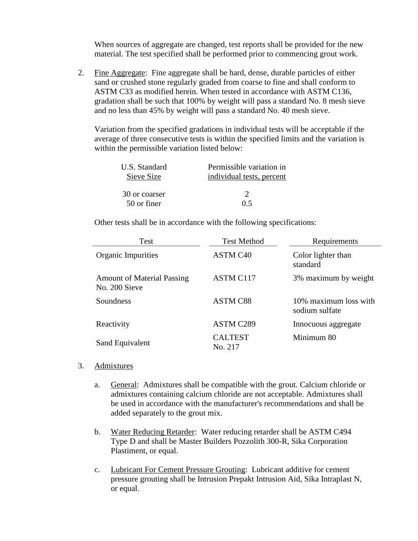
When sources of aggregate are changed, test reports shall be provided for the new
material. The test specified shall be performed prior to commencing grout work.
2. Fine Aggregate: Fine aggregate shall be hard, dense, durable particles of either
sand or crushed stone regularly graded from coarse to fine and shall conform to
ASTM C33 as modified herein. When tested in accordance with ASTM C136,
gradation shall be such that 100% by weight will pass a standard No. 8 mesh sieve
and no less than 45% by weight will pass a standard No. 40 mesh sieve.
Variation from the specified gradations in individual tests will be acceptable if the
average of three consecutive tests is within the specified limits and the variation is
within the permissible variation listed below:
U.S. Standard
Sieve Size
Permissible variation in
individual tests, percent
30 or coarser 2
50 or finer 0.5
Other tests shall be in accordance with the following specifications:
Test Test Method Requirements
Organic Impurities ASTM C40 Color lighter than
standard
Amount of Material Passing
No. 200 Sieve
ASTM C117 3% maximum by weight
Soundness ASTM C88 10% maximum loss with
sodium sulfate
Reactivity ASTM C289 Innocuous aggregate
Sand Equivalent CALTEST
No. 217
Minimum 80
3. Admixtures
a. General: Admixtures shall be compatible with the grout. Calcium chloride or
admixtures containing calcium chloride are not acceptable. Admixtures shall
be used in accordance with the manufacturer's recommendations and shall be
added separately to the grout mix.
b. Water Reducing Retarder: Water reducing retarder shall be ASTM C494
Type D and shall be Master Builders Pozzolith 300-R, Sika Corporation
Plastiment, or equal.
c. Lubricant For Cement Pressure Grouting: Lubricant additive for cement
pressure grouting shall be Intrusion Prepakt Intrusion Aid, Sika Intraplast N,
or equal.
4. Water
Water for washing aggregate, for mixing and for curing shall be free from oil and
deleterious amounts of acids, alkalies, and organic materials; shall not contain
more than 1,000 mg/L of chlorides as Cl-, nor more than 1,300 mg/L of sulfates as
SO4; and shall not contain an amount of impurities that may cause a change of
more than 25% in the setting time of the cement nor a reduction of more than 5%
in the compressive strength of the grout at 14 days when compared with the result
obtained with distilled water. Additionally, water used for curing shall not contain
an amount of impurities sufficient to discolor the grout.
2.02 GROUT
A. Drypack Grout
One part Portland cement and 2 parts fine aggregate, by volume. Grout shall be of
a consistency suitable for the intended purpose and shall be used immediately after
mixing. Grout used under minor bearing plates shall be "drypack" (containing only
enough water to permit placing and packing) and shall be machine mixed. After
placing, all surfaces of the grout shall be cured as per Paragraph 3.06, Protection
and Curing, of Section 03300, CAST-IN-PLACE CONCRETE.
B. Cement Grout
Cement grout shall be a mixture of one part cement, two parts sand, proportioned by
volume, admixtures for pressure grouting, and sufficient water to form a workable mix.
C. Nonshrink Grout
Nonshrink grout shall be nonrusting non-metallic aggregate grout and shall be Master
Builders Masterflow 713, Sika Chemical Corporation Sika Grout 212, or equal.
D. Epoxy Grout
Epoxy grout shall be Master Builders Concresive 1380, Sika Corporation Sikdur 35, as
applicable, or equal.
2.03 PRESSURE GROUTING EQUIPMENT
Pressure grouting equipment shall include a mixer and holdover agitator tanks and shall
be designed to place grout at pressures up to 50 psi. Gages shall be designed to place
grout at pressures up to 50 psi. Gages shall be provided to indicate pressure used. The
mixer shall be provided with a meter capable of indicating to 1/10th of a cubic ft the
volume of grout used.
PART 3 - EXECUTION
3.01 GENERAL
Holes required for grouting shall be blown clean. Horizontal holes for grouting shall be
drilled at a slight downward angle to facilitate holding the grout until setting is
complete.
Bonding compound for use with grout is specified in Section 03300, CAST-IN-PLACE
CONCRETE.
3.02 DRYPACK GROUT
Drypack grout shall be used for built-up surfaces, setting miscellaneous metal items and
minor repairs. Grout used under minor bearing plates shall also be drypack grout.
Surfaces required to be built up with drypack grout shall be roughened by brushing,
cleaned, and coated with bonding compound specified in Paragraph 2.01L, Section
03300, CAST-IN-PLACE CONCRETE, before the application of the grout. The
drypack grout shall be applied immediately following the application of the bonding
compound in bands or strips to form a covering of the required thickness. The covering
shall be smooth. Construction joints in the grout shall be sloped and shall be cleaned and
wetted before application is resumed.
Drypack grout shall be cured in accordance with Section 03300, CAST-IN-PLACE
CONCRETE.
Grout shall not be placed when ambient temperature is below 40°F or when it is likely
that the ambient temperature will fall below 40°F during or within 48 hrs of placement,
unless adequate protection is provided.
3.03 CEMENT GROUT
Cement grout shall be used for filling nonbearing portions of equipment pads and
pressure grouting.
Except for the specialized equipment for pressure grouting, mixing and placing
apparatus shall be similar to that normally used for cast-in-place concrete. Diluted grout
shall be agitated to keep ingredients mixed.
3.04 NONSHRINK GROUT
Nonshrink grout shall be used for the bearing surfaces of machinery and equipment
bases, column baseplates and bearing plates. Nonshrink grout also shall be used for
setting bolts and reinforcing steel in holes for grouting.
Where specified, nonshrink grout shall meet the requirements of CRD-C621. Grout
shall be placed in accordance with manufacturer's instructions.
3.05 EPOXY GROUT
Epoxy grout shall be used for repairing cracks by pressure grouting and repairing
structural concrete. Epoxy grout shall be HILTI CI 060 EP, Simpson's ETI injection
system, or approved equal. Concrete shall be primed in accordance with the grout
manufacturer's instructions.
3.06 PRESSURE GROUTING
Prior to grouting, systems and holes to be grouted shall be washed clean. Washing is not
required for grouting soil voids outside pipe cylinders or casing pipes. Grouting, once
commenced, shall be completed without stoppage. In case of breakdown of equipment,
the Contractor shall wash out the grouting system sufficiently to ensure fresh grout and
adequate bond and penetration will occur upon restarting the grouting operation. Grout
pressure shall be maintained until grout has set.
**END OF SECTION**
SECTION 09800
PAINTING AND SPECIAL COATING SYSTEMS
PART 1 - GENERAL
1.01 SCOPE
The work covered by this section consists of furnishing all labor, equipment and
material necessary to perform surface preparation and to furnish and apply all paint,
protective coatings and finishes as specified herein and/or as indicated on the plans.
1.02 QUALITY ASSURANCE
A. References
The publications referred to hereinafter form a part of this specifications to the extent
referenced. The publications are referred to in the text by the basic designation only. The
latest edition of referenced publications in effect at the time of the bid shall govern. In
case of conflict between the requirements of this section and the listed standards, the
requirements of this section shall prevail.
American Society for Testing and Materials Publication (ASTM)
ASTM D1653 Test Method for Water Vapor Permeability of Organic
Coating Films
ASTM D2200 Pictorial Surface Preparation Standards for Painting
Steel Surfaces
ASTM D3960 Practice for Determining Volatile Organic Contents
(VOC) of Paints and Related Coatings
ASTM D4258 Practice for Surface Cleaning Concrete for Coating
ASTM D4259 Standard Practice for Abrading Concrete
ASTM D4585 Standard Practice for Testing Water Resistance of
Coatings Using Controlled Condensation
ASTM E84 Test Method for Surface Burning Characteristics of
Building Materials
Federal Specifications (Fed. Spec.) Publications
Fed. Spec. TT-C-555 Coating, Textured (for Interior and Exterior Masonry
Surfaces)
The Society for Protective Coatings; formally known as Steel Structures Painting
Council (SSPC) Specifications
SSPC-SP-1 Solvent Cleaning
SSPC-SP-2 Hand Tool Cleaning
SSPC-SP-5/NACE 1 White Metal Blash Cleaning
SSPC-SP-6/NACE 3 Commercial Blast Cleaning
SSPC-SP-7/NACE 4 Brush-Off Blast Cleaning
SSPC-SP-10/NACE 2 Near-White Blast Cleaning
B. Experience
The Coating subcontractor shall hold a current C-33 painting and decorating license and
have a minimum of 5 years practical experience and successful history in the application
of specified products to surfaces. He shall substantiate this requirement by furnishing a
list of six references of similar projects.
1.03 SUBMITTALS
The Contractor shall submit information in accordance with Section 01300,
SUBMITTALS, to substantiate compliance with this specification. In addition, the
following specific information shall be provided.
A. Manufacturer’s Data
1. Manufacturer's Product Data Sheets including complete data on each type of
paint and primer.
2. Material Safety Data Sheets (MSDS).
3. Manufacturer's published surface preparation application instructions.
. 4. Color charts for each paint for color selection by City.
1.04 DELIVERY AND STORAGE
All materials shall be delivered to the site in the manufacturer's sealed containers. Each
container shall be labeled by the manufacturer, and the label shall be intact upon
delivery. Labels shall give the manufacturer's name, brand, type of paint, batch number,
color of paint, date of manufacture, storage life and instructions for reducing. Job
mixing or job tinting may be done when approved by the City for sample colors.
The Contractor shall store all materials and equipment in a storage place protected from
weather and excessive heat and cold. Necessary precautions shall be taken to reduce
hazards to a minimum. Materials exceeding the storage life recommended by the
manufacturer shall be removed from the site.
Where shop-primed or shop-finished items are to be shipped to the job site, protect
coatings from damage by the use of battens, padded straps, and nonmetallic slings.
Excessive shipping damage will be considered grounds for rejection of shop primers and
shop finishes.
1.05 ENVIRONMENTAL CONTROLS
A. Provide ambient temperatures recommended by manufacturer of material to be
applied.
B. Provide adequate ventilation and safety measures for Contractor's employees.
C. Provide adequate illumination on all surfaces in areas to be painted, including
floors, walls and ceilings, even though they do not require painting.
D. Use temporary dust barriers to close off areas being painted from areas where other
work is being performed.
1.06 COMPLIANCE WITH REGULATORY REQUIREMENTS
All applicable federal, state, and local regulatory agency requirements shall be complied
with during the course of the work. The Contractor’s attention is directed to the
following list of agency requirements that generally apply to coatings work; the
Contractor is responsible for identifying and complying with any other agencies or
requirements not listed.
1. OSHA - Personnel protection during all phases of work, including exposure to
airborne solvents, dust, and lead.
2. CAL/OSHA - Personnel protection; requirements may supersede OSHA regulations.
3. California Title 22 - Environmental requirements, including definition of abrasive
blast materials and residue relative to hazardous waste disposal requirements.
4. Air Quality Management City - Environmental requirements for limiting airborne
emissions from equipment, products, and methods of operation.
1.07 MANUFACTURER’S REPRESENTATIVE
The coating manufacturer shall provide a representative to visit the job site at intervals
during surface preparation and coating as may be required for product application
quality assurance, and to determine compliance with manufacturer’s instructions and
these specifications, and as may be necessary to resolve field problems attributable to,
or associated with, the manufacturer’s products furnished under this contract.
PART 2 - PRODUCTS
2.01 MATERIALS
All paint and coating materials furnished for each coating system shall be new products
of a single manufacturer.
Only compatible materials shall be used in the work. Particular attention shall be
directed to compatibility of primers and finish coats.
The volatile organic content (VOC) of the applied coatings, as determined in accordance
with ASTM D3960, shall comply with prevailing air pollution regulations.
Regulations prohibit the manufacture, sale, or application of Architectural Coatings and
Specialty Coatings having greater than stipulated levels of volatile organic compounds
measured in grams per liter by weight of coating as applied, after January 1, 1988.
The Contractor shall base his own bid on using the products specified. If the specified
products are not available in formulations that meet applicable regulations on VOC
levels at time of application, the Contractor shall submit for review products of
equivalent quality and function that comply with regulations in effect at that time.
If the Contractor applies any coatings which do not meet regulations as referred to in
this Section for VOC content, or if he applies coatings that have been modified or
thinned other than as recommended by manufacturer, he shall be responsible for any
fines, costs, remedies, or legal actions that may result.
The paints, primers and coating shall be the product of the Ameron Protective Coatings
Group, Brea, CA; Sherwin-Williams, Industrial Maintenance Coatings, Cleveland, OH;
Tnemec Company, Inc., North Kansas City, MO; ICI-Devoe Coatings, Cleveland, OH;
the Carboline Company, St. Louis, MO, or equal. Examples of paint systems from four
manufacturers are listed in the following specifications. The "or equal" clause refers to
dry film thickness (solids content), generic type of primer, paint, or coating, and
ingredients in the coating system. The coating must be recommended for each service.
No request for substitution for an "or equal" will be considered which decreases the film
thickness designated, the number of coats to be applied, solids content by volume, the
general type of coating, paint, or primer, or the quantity, quality and type of ingredients
in the coatings specified. The Contractor shall provide a list of references where coating
of the same generic type has been applied on similar projects. The reference list shall
give the project name, city, state, owner, phone number of owner, coating system
reference and number, and year coating was applied. Paints not listed in these
specifications shall be submitted with certified ingredients analysis so that a complete
comparison between specified and proposed paint may be made by the Construction
Manager.
PART 3 - EXECUTION
3.01 COATINGS
A. General
Coating products shall not be used until the Construction Manager has inspected the
materials. Adequate ventilation shall be used at all times. Adequate illumination shall be
provided on all surfaces in areas to be painted.
B. Coating Systems
1. Shop Applied Prime Coat: Except as otherwise specified, prime coats may be shop
or field applied. Shop applied primer shall be compatible with the specific coating
system and shall be applied at the minimum dry film thickness recommended by
the manufacturer. Approved submittal data identifying the shop primer used shall
be provided to the onsite finish coat applicator and to the Construction Manager
before delivery of items to the jobsite. Damaged, deteriorated and poorly applied
shop coatings that do not meet the requirements of this section shall be removed
and replaced by a field coating. The field coating may consist of touching up the
shop prime coat and then applying the finish coats to achieve the specified film
thickness and continuity.
2. Field Coats: Field coats shall consist of one or more prime coats and one or more
finish coats to build up the coating to the specified dry film thickness. Finish coats
shall be not be applied until other work in the area is complete and until the prime
and intermediate coats have been inspected by the Construction Manager.
3.02 PREPARATION
A. General
All surfaces to be coated or painted shall be in the proper condition to receive the
material specified before any coating or painting is performed. Substrates shall be
prepared in strict accordance with coating system manufacturer's requirements. Primers
shall be used where coatings are not self-priming whether specified herein or not. No
more abrasive blasting or surface preparation than can be coated or painted in a normal
working day will be permitted unless approved in writing by the Construction Manager.
All sharp edges, burrs and weld spatter shall be removed. The following levels of
surface preparation are subsequently referred to:
1. White Metal Blast Cleaning (SSPC-SP-5): Removal of all visible rust, mill scale,
paint, and foreign matter by blast cleaning by wheel or nozzle (dry) using sand,
grit, or shot.
2. Near-White Blast Cleaning (SSPC-SP-10): Blast cleaning nearly to white metal
cleanliness until at least 95% of each element of surface area is free of all visible
residues.
3. Commercial Blast (SSPC-SP-6): Blast cleaning until at least 67% of each element
of surface area is free of all visible residues.
4. Brush-Off Blast Cleaning (SSPC-SP-7): Blast cleaning of all except tightly
adhering residues of mill scale, rust, and coatings, exposing numerous evenly
distributed flecks of underlying metal.
5. Solvent Cleaning (SSPC-SP-1): Removal of all grease, oil and dirt.
Clean cloths and clean fluids shall be used in solvent cleaning. Cleaning and painting
shall be scheduled so that dust and spray from the cleaning process will not fall on wet,
newly painted surfaces. Hardware, electrical fixtures and similar accessories shall be
removed or masked during preparation and paint operations, or shall otherwise be
satisfactorily protected. Equipment adjacent to walls shall be disconnected and moved to
permit cleaning and painting of equipment and walls and, following painting, shall be
replaced and reconnected.
B. Metallic Surfaces
Metallic surfaces shall be prepared in accordance with applicable portions of surface
preparation specifications of the Society for Protective Coatings, formally the Steel
Structures Painting Council (SSPC) specified in each coating system. The solvent in
solvent cleaning operations shall be as recommended by the manufacturer.
Preparation of metallic surfaces shall be based upon comparison with ASTM D2200,
and as described herein. To facilitate inspection, the Contractor shall, on the first day of
abrasive blasting operations, abrasive blast metal panels to the standards specified.
Plates shall measure a minimum of 8-1/2 in. x 11 in. Panels shall measure a minimum of
8-1/2 in. x 11 in. Panels meeting the requirements of the specifications shall be
initialized by the Contractor and coated with a clear non-yellowing finish. One of these
panels shall be prepared for each type of abrasive blasting and shall be used as the
comparison standard throughout the project.
C. Detailed Surface Preparation
Surface preparations for each type of surface shall be in accordance with the specific
requirements of each coating system.
D. Existing Facilities – Touch Up and Recoating
Unless otherwise specified, existing coating systems damaged by new construction shall
be repaired and coated in accordance with the appropriate system specified for new
work.
Contractor shall demonstrate that the existing coating is compatible with field coating
by applying small test patches of specific paints over existing coatings. If the existing
coating is not compatible with the field coat (it lifts or ripples), the existing coating shall
be reprimed with a primer compatible with both the existing coating shall be reprimed
with a primer compatible with both the existing coating and the field applied paint, or
replaced with the proper prime coat. The primer shall be as recommended by the
manufacturer of the field applied paints.
The Contractor has the option of completely removing the existing coating before
applying the specified coating.
3.03 APPLICATION
A. Workmanship
Each coat of paint shall be of the consistency as supplied by the manufacturer, or
thinned if necessary, and applied in accordance with the manufacturer's written
instructions. Each coat shall be well brushed, rolled, or sprayed to obtain a uniform and
evenly applied finish. Work shall be free from "runs", "bridges", "shiners", or other
imperfections due to faulty intervals. Particular care shall be taken to obtain a uniform,
unbroken coating over all bolts, threads, nuts, welds, edges and corners. Further, all
weld splatter shall be removed and all welds neutralized with thinner.
B. Paint Properties, Mixing and Thinning
Paint, when applied, shall provide a satisfactory film and smooth even surface, and
glossy undercoats shall be lightly sanded to provide a surface suitable for the proper
application and adhesion of subsequent coats. Paints shall be thoroughly stirred,
strained, and kept at a uniform consistency during application. Coatings consisting of
two or more components shall be mixed in accordance with the manufacturer's
instructions. Unless otherwise specified, paint shall not be reduced more than necessary
to obtain the proper application characteristics. Thinner shall be both type and amount
as recommended by the coating manufacturer.
C. Environmental Conditions
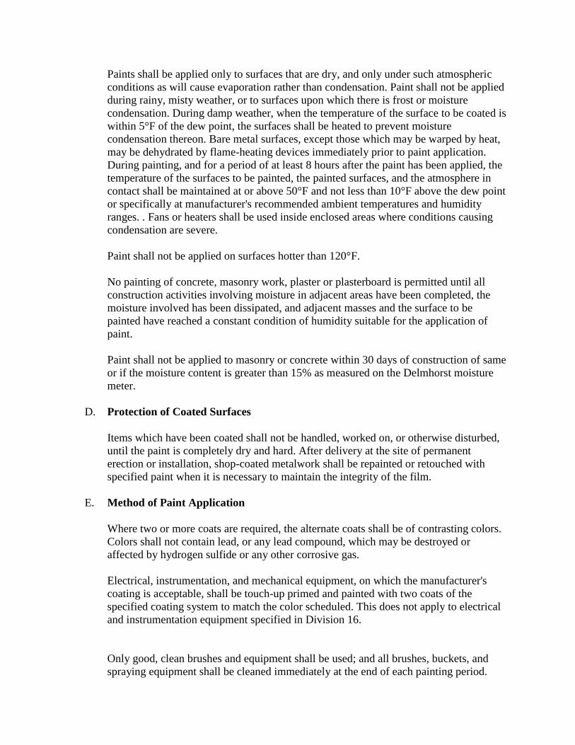
Paints shall be applied only to surfaces that are dry, and only under such atmospheric
conditions as will cause evaporation rather than condensation. Paint shall not be applied
during rainy, misty weather, or to surfaces upon which there is frost or moisture
condensation. During damp weather, when the temperature of the surface to be coated is
within 5°F of the dew point, the surfaces shall be heated to prevent moisture
condensation thereon. Bare metal surfaces, except those which may be warped by heat,
may be dehydrated by flame-heating devices immediately prior to paint application.
During painting, and for a period of at least 8 hours after the paint has been applied, the
temperature of the surfaces to be painted, the painted surfaces, and the atmosphere in
contact shall be maintained at or above 50°F and not less than 10°F above the dew point
or specifically at manufacturer's recommended ambient temperatures and humidity
ranges. . Fans or heaters shall be used inside enclosed areas where conditions causing
condensation are severe.
Paint shall not be applied on surfaces hotter than 120°F.
No painting of concrete, masonry work, plaster or plasterboard is permitted until all
construction activities involving moisture in adjacent areas have been completed, the
moisture involved has been dissipated, and adjacent masses and the surface to be
painted have reached a constant condition of humidity suitable for the application of
paint.
Paint shall not be applied to masonry or concrete within 30 days of construction of same
or if the moisture content is greater than 15% as measured on the Delmhorst moisture
meter.
D. Protection of Coated Surfaces
Items which have been coated shall not be handled, worked on, or otherwise disturbed,
until the paint is completely dry and hard. After delivery at the site of permanent
erection or installation, shop-coated metalwork shall be repainted or retouched with
specified paint when it is necessary to maintain the integrity of the film.
E. Method of Paint Application
Where two or more coats are required, the alternate coats shall be of contrasting colors.
Colors shall not contain lead, or any lead compound, which may be destroyed or
affected by hydrogen sulfide or any other corrosive gas.
Electrical, instrumentation, and mechanical equipment, on which the manufacturer's
coating is acceptable, shall be touch-up primed and painted with two coats of the
specified coating system to match the color scheduled. This does not apply to electrical
and instrumentation equipment specified in Division 16.
Only good, clean brushes and equipment shall be used; and all brushes, buckets, and
spraying equipment shall be cleaned immediately at the end of each painting period.
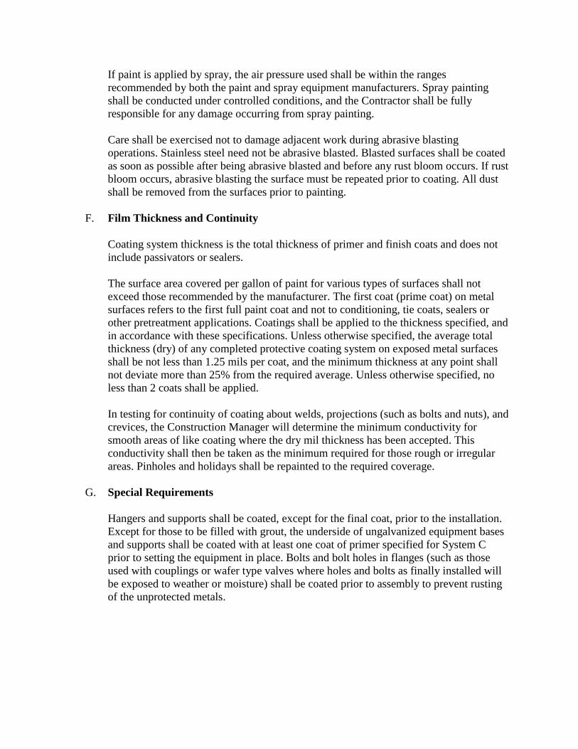
If paint is applied by spray, the air pressure used shall be within the ranges
recommended by both the paint and spray equipment manufacturers. Spray painting
shall be conducted under controlled conditions, and the Contractor shall be fully
responsible for any damage occurring from spray painting.
Care shall be exercised not to damage adjacent work during abrasive blasting
operations. Stainless steel need not be abrasive blasted. Blasted surfaces shall be coated
as soon as possible after being abrasive blasted and before any rust bloom occurs. If rust
bloom occurs, abrasive blasting the surface must be repeated prior to coating. All dust
shall be removed from the surfaces prior to painting.
F. Film Thickness and Continuity
Coating system thickness is the total thickness of primer and finish coats and does not
include passivators or sealers.
The surface area covered per gallon of paint for various types of surfaces shall not
exceed those recommended by the manufacturer. The first coat (prime coat) on metal
surfaces refers to the first full paint coat and not to conditioning, tie coats, sealers or
other pretreatment applications. Coatings shall be applied to the thickness specified, and
in accordance with these specifications. Unless otherwise specified, the average total
thickness (dry) of any completed protective coating system on exposed metal surfaces
shall be not less than 1.25 mils per coat, and the minimum thickness at any point shall
not deviate more than 25% from the required average. Unless otherwise specified, no
less than 2 coats shall be applied.
In testing for continuity of coating about welds, projections (such as bolts and nuts), and
crevices, the Construction Manager will determine the minimum conductivity for
smooth areas of like coating where the dry mil thickness has been accepted. This
conductivity shall then be taken as the minimum required for those rough or irregular
areas. Pinholes and holidays shall be repainted to the required coverage.
G. Special Requirements
Hangers and supports shall be coated, except for the final coat, prior to the installation.
Except for those to be filled with grout, the underside of ungalvanized equipment bases
and supports shall be coated with at least one coat of primer specified for System C
prior to setting the equipment in place. Bolts and bolt holes in flanges (such as those
used with couplings or wafer type valves where holes and bolts as finally installed will
be exposed to weather or moisture) shall be coated prior to assembly to prevent rusting
of the unprotected metals.
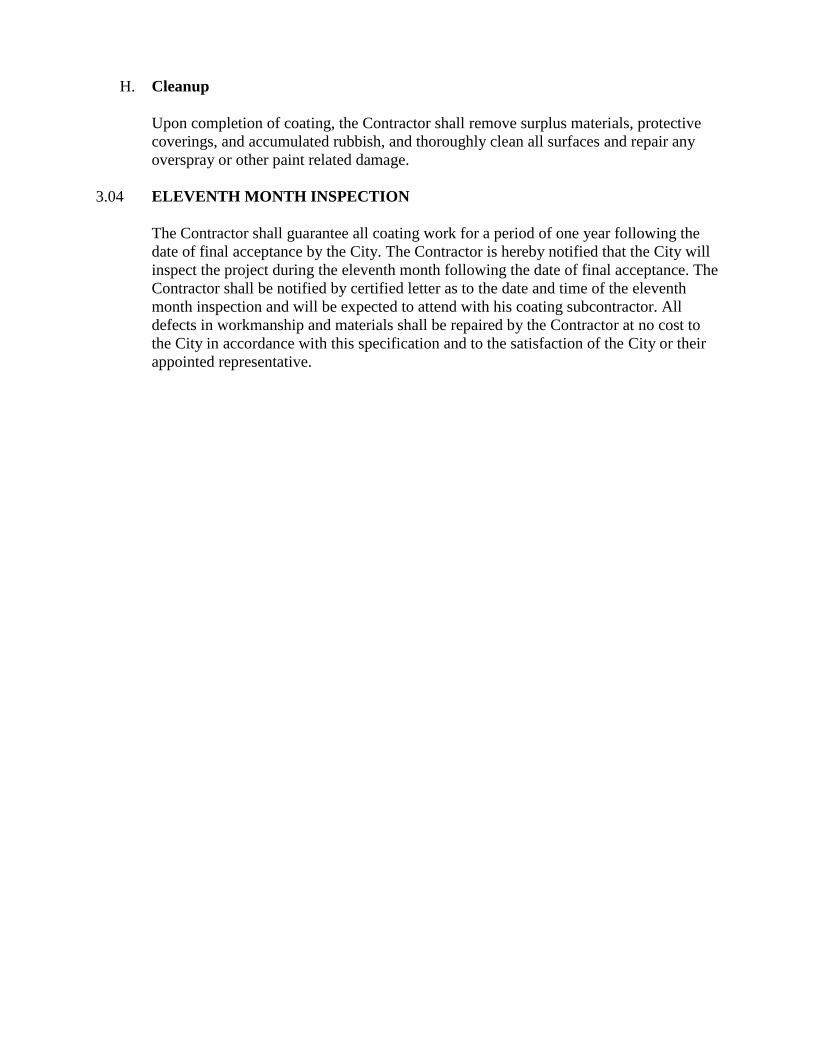
H. Cleanup
Upon completion of coating, the Contractor shall remove surplus materials, protective
coverings, and accumulated rubbish, and thoroughly clean all surfaces and repair any
overspray or other paint related damage.
3.04 ELEVENTH MONTH INSPECTION
The Contractor shall guarantee all coating work for a period of one year following the
date of final acceptance by the City. The Contractor is hereby notified that the City will
inspect the project during the eleventh month following the date of final acceptance. The
Contractor shall be notified by certified letter as to the date and time of the eleventh
month inspection and will be expected to attend with his coating subcontractor. All
defects in workmanship and materials shall be repaired by the Contractor at no cost to
the City in accordance with this specification and to the satisfaction of the City or their
appointed representative.
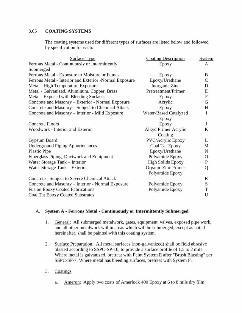
3.05 COATING SYSTEMS
The coating systems used for different types of surfaces are listed below and followed
by specification for each:
Surface Type Coating Description System
Ferrous Metal - Continuously or Intermittently
Submerged
Epoxy A
Ferrous Metal - Exposure to Moisture or Fumes Epoxy B
Ferrous Metal - Interior and Exterior -Normal Exposure Epoxy/Urethane C
Metal - High Temperature Exposure Inorganic Zinc D
Metal - Galvanized, Aluminum, Copper, Brass Pretreatment/Primer E
Metal - Exposed with Bleeding Surfaces Epoxy F
Concrete and Masonry – Exterior - Normal Exposure Acrylic G
Concrete and Masonry – Subject to Chemical Attack Epoxy H
Concrete and Masonry – Interior - Mild Exposure Water-Based Catalyzed
Epoxy
I
Concrete Floors Epoxy J
Woodwork - Interior and Exterior Alkyd Primer Acrylic
Coating
K
Gypsum Board PVC/Acrylic Epoxy L
Underground Piping Appurtenances Coal Tar Epoxy M
Plastic Pipe Epoxy/Urethane N
Fiberglass Piping, Ductwork and Equipment Polyamide Epoxy O
Water Storage Tank – Interior High Solids Epoxy P
Water Storage Tank – Exterior Organic Zinc Primer
Polyamide Epoxy
Q
Concrete - Subject to Severe Chemical Attack R
Concrete and Masonry – Interior - Normal Exposure Polyamide Epoxy S
Fusion Epoxy Coated Fabrications Polyamide Epoxy T
Coal Tar Epoxy Coated Substrates U
A. System A - Ferrous Metal - Continuously or Intermittently Submerged
1. General: All submerged metalwork, gates, equipment, valves, exposed pipe work,
and all other metalwork within areas which will be submerged, except as noted
hereinafter, shall be painted with this coating system.
2. Surface Preparation: All metal surfaces (non-galvanized) shall be field abrasive
blasted according to SSPC-SP-10, to provide a surface profile of 1.5 to 2 mils.
Where metal is galvanized, pretreat with Paint System E after "Brush Blasting" per
SSPC-SP-7. Where metal has bleeding surfaces, pretreat with System F.
3. Coatings
a. Ameron: Apply two coats of Amerlock 400 Epoxy at 6 to 8 mils dry film
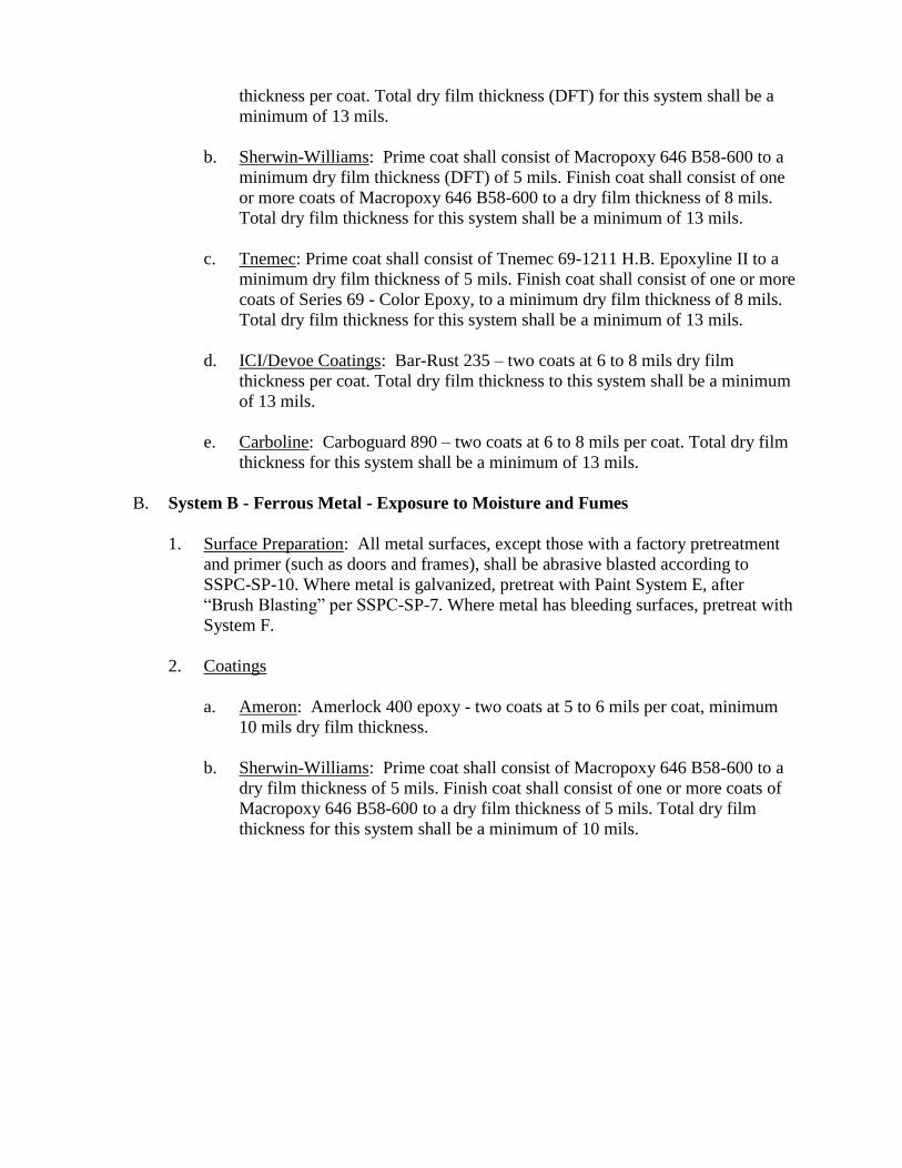
thickness per coat. Total dry film thickness (DFT) for this system shall be a
minimum of 13 mils.
b. Sherwin-Williams: Prime coat shall consist of Macropoxy 646 B58-600 to a
minimum dry film thickness (DFT) of 5 mils. Finish coat shall consist of one
or more coats of Macropoxy 646 B58-600 to a dry film thickness of 8 mils.
Total dry film thickness for this system shall be a minimum of 13 mils.
c. Tnemec: Prime coat shall consist of Tnemec 69-1211 H.B. Epoxyline II to a
minimum dry film thickness of 5 mils. Finish coat shall consist of one or more
coats of Series 69 - Color Epoxy, to a minimum dry film thickness of 8 mils.
Total dry film thickness for this system shall be a minimum of 13 mils.
d. ICI/Devoe Coatings: Bar-Rust 235 – two coats at 6 to 8 mils dry film
thickness per coat. Total dry film thickness to this system shall be a minimum
of 13 mils.
e. Carboline: Carboguard 890 – two coats at 6 to 8 mils per coat. Total dry film
thickness for this system shall be a minimum of 13 mils.
B. System B - Ferrous Metal - Exposure to Moisture and Fumes
1. Surface Preparation: All metal surfaces, except those with a factory pretreatment
and primer (such as doors and frames), shall be abrasive blasted according to
SSPC-SP-10. Where metal is galvanized, pretreat with Paint System E, after
“Brush Blasting” per SSPC-SP-7. Where metal has bleeding surfaces, pretreat with
System F.
2. Coatings
a. Ameron: Amerlock 400 epoxy - two coats at 5 to 6 mils per coat, minimum
10 mils dry film thickness.
b. Sherwin-Williams: Prime coat shall consist of Macropoxy 646 B58-600 to a
dry film thickness of 5 mils. Finish coat shall consist of one or more coats of
Macropoxy 646 B58-600 to a dry film thickness of 5 mils. Total dry film
thickness for this system shall be a minimum of 10 mils.
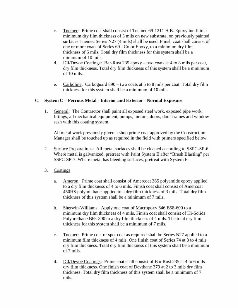
c. Tnemec: Prime coat shall consist of Tnemec 69-1211 H.B. Epoxyline II to a
minimum dry film thickness of 5 mils on new substrate, on previously painted
surfaces Tnemec Series N27 (4 mils) shall be used. Finish coat shall consist of
one or more coats of Series 69 - Color Epoxy, to a minimum dry film
thickness of 5 mils. Total dry film thickness for this system shall be a
minimum of 10 mils.
d. ICI/Devoe Coatings: Bar-Rust 235 epoxy – two coats at 4 to 8 mils per coat,
dry film thickness. Total dry film thickness of this system shall be a minimum
of 10 mils.
e. Carboline: Carboguard 890 – two coats at 5 to 8 mils per coat. Total dry film
thickness for this system shall be a minimum of 10 mils.
C. System C – Ferrous Metal - Interior and Exterior - Normal Exposure
1. General: The Contractor shall paint all exposed steel work, exposed pipe work,
fittings, all mechanical equipment, pumps, motors, doors, door frames and window
sash with this coating system.
All metal work previously given a shop prime coat approved by the Construction
Manager shall be touched up as required in the field with primers specified below.
2. Surface Preparations: All metal surfaces shall be cleaned according to SSPC-SP-6.
Where metal is galvanized, pretreat with Paint System E after “Brush Blasting” per
SSPC-SP-7. Where metal has bleeding surfaces, pretreat with System F.
3. Coatings
a. Ameron: Prime coat shall consist of Amercoat 385 polyamide epoxy applied
to a dry film thickness of 4 to 6 mils. Finish coat shall consist of Amercoat
450HS polyurethane applied to a dry film thickness of 3 mils. Total dry film
thickness of this system shall be a minimum of 7 mils.
b. Sherwin-Williams: Apply one coat of Macropoxy 646 B58-600 to a
minimum dry film thickness of 4 mils. Finish coat shall consist of Hi-Solids
Polyurethane B65-300 to a dry film thickness of 4 mils. The total dry film
thickness for this system shall be a minimum of 7 mils.
c. Tnemec: Prime coat or spot coat as required shall be Series N27 applied to a
minimum film thickness of 4 mils. One finish coat of Series 74 at 3 to 4 mils
dry film thickness. Total dry film thickness of this system shall be a minimum
of 7 mils.
d. ICI/Devoe Coatings: Prime coat shall consist of Bar Rust 235 at 4 to 6 mils
dry film thickness. One finish coat of Devthane 379 at 2 to 3 mils dry film
thickness. Total dry film thickness of this system shall be a minimum of 7
mils.
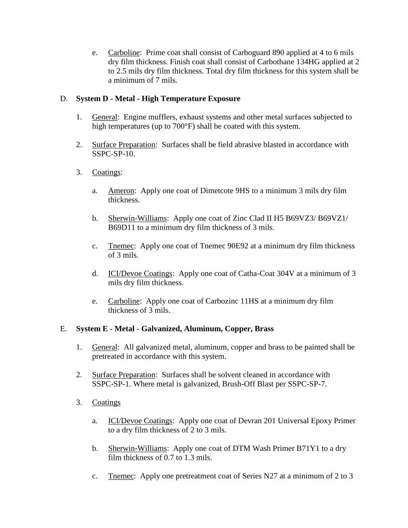
e. Carboline: Prime coat shall consist of Carboguard 890 applied at 4 to 6 mils
dry film thickness. Finish coat shall consist of Carbothane 134HG applied at 2
to 2.5 mils dry film thickness. Total dry film thickness for this system shall be
a minimum of 7 mils.
D. System D - Metal - High Temperature Exposure
1. General: Engine mufflers, exhaust systems and other metal surfaces subjected to
high temperatures (up to 700°F) shall be coated with this system.
2. Surface Preparation: Surfaces shall be field abrasive blasted in accordance with
SSPC-SP-10.
3. Coatings:
a. Ameron: Apply one coat of Dimetcote 9HS to a minimum 3 mils dry film
thickness.
b. Sherwin-Williams: Apply one coat of Zinc Clad II H5 B69VZ3/ B69VZ1/
B69D11 to a minimum dry film thickness of 3 mils.
c. Tnemec: Apply one coat of Tnemec 90E92 at a minimum dry film thickness
of 3 mils.
d. ICI/Devoe Coatings: Apply one coat of Catha-Coat 304V at a minimum of 3
mils dry film thickness.
e. Carboline: Apply one coat of Carbozinc 11HS at a minimum dry film
thickness of 3 mils.
E. System E - Metal - Galvanized, Aluminum, Copper, Brass
1. General: All galvanized metal, aluminum, copper and brass to be painted shall be
pretreated in accordance with this system.
2. Surface Preparation: Surfaces shall be solvent cleaned in accordance with
SSPC-SP-1. Where metal is galvanized, Brush-Off Blast per SSPC-SP-7.
3. Coatings
a. ICI/Devoe Coatings: Apply one coat of Devran 201 Universal Epoxy Primer
to a dry film thickness of 2 to 3 mils.
b. Sherwin-Williams: Apply one coat of DTM Wash Primer B71Y1 to a dry
film thickness of 0.7 to 1.3 mils.
c. Tnemec: Apply one pretreatment coat of Series N27 at a minimum of 2 to 3
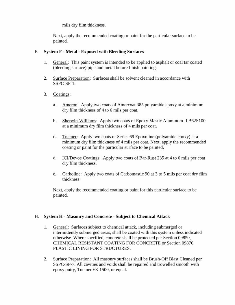
mils dry film thickness.
Next, apply the recommended coating or paint for the particular surface to be
painted.
F. System F - Metal - Exposed with Bleeding Surfaces
1. General: This paint system is intended to be applied to asphalt or coal tar coated
(bleeding surface) pipe and metal before finish painting.
2. Surface Preparation: Surfaces shall be solvent cleaned in accordance with
SSPC-SP-1.
3. Coatings:
a. Ameron: Apply two coats of Amercoat 385 polyamide epoxy at a minimum
dry film thickness of 4 to 6 mils per coat.
b. Sherwin-Williams: Apply two coats of Epoxy Mastic Aluminum II B62S100
at a minimum dry film thickness of 4 mils per coat.
c. Tnemec: Apply two coats of Series 69 Epoxoline (polyamide epoxy) at a
minimum dry film thickness of 4 mils per coat. Next, apply the recommended
coating or paint for the particular surface to be painted.
d. ICI/Devoe Coatings: Apply two coats of Bar-Rust 235 at 4 to 6 mils per coat
dry film thickness.
e. Carboline: Apply two coats of Carbomastic 90 at 3 to 5 mils per coat dry film
thickness.
Next, apply the recommended coating or paint for this particular surface to be
painted.
H. System H - Masonry and Concrete - Subject to Chemical Attack
1. General: Surfaces subject to chemical attack, including submerged or
intermittently submerged areas, shall be coated with this system unless indicated
otherwise. Where specified, concrete shall be protected per Section 09850,
CHEMICAL RESISTANT COATING FOR CONCRETE or Section 09876,
PLASTIC LINING FOR STRUCTURES.
2. Surface Preparation: All masonry surfaces shall be Brush-Off Blast Cleaned per
SSPC-SP-7. All cavities and voids shall be repaired and trowelled smooth with
epoxy putty, Tnemec 63-1500, or equal.
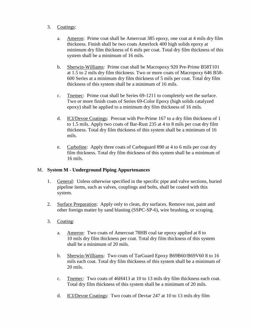
3. Coatings:
a. Ameron: Prime coat shall be Amercoat 385 epoxy, one coat at 4 mils dry film
thickness. Finish shall be two coats Amerlock 400 high solids epoxy at
minimum dry film thickness of 6 mils per coat. Total dry film thickness of this
system shall be a minimum of 16 mils.
b. Sherwin-Williams: Prime coat shall be Macropoxy 920 Pre-Prime B58T101
at 1.5 to 2 mils dry film thickness. Two or more coats of Macropoxy 646 B58-
600 Series at a minimum dry film thickness of 5 mils per coat. Total dry film
thickness of this system shall be a minimum of 16 mils.
c. Tnemec: Prime coat shall be Series 69-1211 to completely wet the surface.
Two or more finish coats of Series 69-Color Epoxy (high solids catalyzed
epoxy) shall be applied to a minimum dry film thickness of 16 mils.
d. ICI/Devoe Coatings: Precoat with Pre-Prime 167 to a dry film thickness of 1
to 1.5 mils. Apply two coats of Bar-Rust 235 at 4 to 8 mils per coat dry film
thickness. Total dry film thickness of this system shall be a minimum of 16
mils.
e. Carboline: Apply three coats of Carboguard 890 at 4 to 6 mils per coat dry
film thickness. Total dry film thickness of this system shall be a minimum of
16 mils.
M. System M - Underground Piping Appurtenances
1. General: Unless otherwise specified in the specific pipe and valve sections, buried
pipeline items, such as valves, couplings and bolts, shall be coated with this
system.
2. Surface Preparation: Apply only to clean, dry surfaces. Remove rust, paint and
other foreign matter by sand blasting (SSPC-SP-6), wire brushing, or scraping.
3. Coating:
a. Ameron: Two coats of Amercoat 78HB coal tar epoxy applied at 8 to
10 mils dry film thickness per coat. Total dry film thickness of this system
shall be a minimum of 20 mils.
b. Sherwin-Williams: Two coats of TarGuard Epoxy B69B60/B69V60 8 to 16
mils each coat. Total dry film thickness of this system shall be a minimum of
20 mils.
c. Tnemec: Two coats of 46H413 at 10 to 13 mils dry film thickness each coat.
Total dry film thickness of this system shall be a minimum of 20 mils.
d. ICI/Devoe Coatings: Two coats of Devtar 247 at 10 to 13 mils dry film
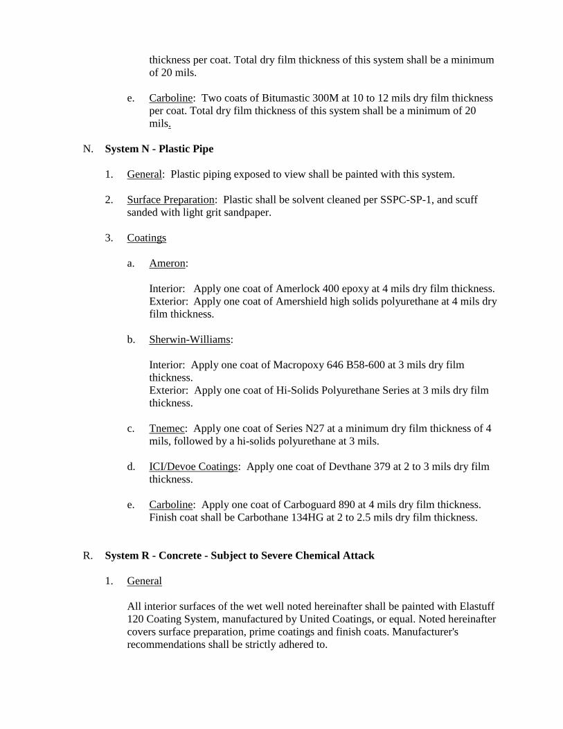
thickness per coat. Total dry film thickness of this system shall be a minimum
of 20 mils.
e. Carboline: Two coats of Bitumastic 300M at 10 to 12 mils dry film thickness
per coat. Total dry film thickness of this system shall be a minimum of 20
mils.
N. System N - Plastic Pipe
1. General: Plastic piping exposed to view shall be painted with this system.
2. Surface Preparation: Plastic shall be solvent cleaned per SSPC-SP-1, and scuff
sanded with light grit sandpaper.
3. Coatings
a. Ameron:
Interior: Apply one coat of Amerlock 400 epoxy at 4 mils dry film thickness.
Exterior: Apply one coat of Amershield high solids polyurethane at 4 mils dry
film thickness.
b. Sherwin-Williams:
Interior: Apply one coat of Macropoxy 646 B58-600 at 3 mils dry film
thickness.
Exterior: Apply one coat of Hi-Solids Polyurethane Series at 3 mils dry film
thickness.
c. Tnemec: Apply one coat of Series N27 at a minimum dry film thickness of 4
mils, followed by a hi-solids polyurethane at 3 mils.
d. ICI/Devoe Coatings: Apply one coat of Devthane 379 at 2 to 3 mils dry film
thickness.
e. Carboline: Apply one coat of Carboguard 890 at 4 mils dry film thickness.
Finish coat shall be Carbothane 134HG at 2 to 2.5 mils dry film thickness.
R. System R - Concrete - Subject to Severe Chemical Attack
1. General
All interior surfaces of the wet well noted hereinafter shall be painted with Elastuff
120 Coating System, manufactured by United Coatings, or equal. Noted hereinafter
covers surface preparation, prime coatings and finish coats. Manufacturer's
recommendations shall be strictly adhered to.
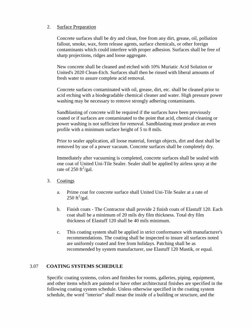
2. Surface Preparation
Concrete surfaces shall be dry and clean, free from any dirt, grease, oil, pollution
fallout, smoke, wax, form release agents, surface chemicals, or other foreign
contaminants which could interfere with proper adhesion. Surfaces shall be free of
sharp projections, ridges and loose aggregate.
New concrete shall be cleaned and etched with 10% Muriatic Acid Solution or
United's 2020 Clean-Etch. Surfaces shall then be rinsed with liberal amounts of
fresh water to assure complete acid removal.
Concrete surfaces contaminated with oil, grease, dirt, etc. shall be cleaned prior to
acid etching with a biodegradable chemical cleaner and water. High pressure power
washing may be necessary to remove strongly adhering contaminants.
Sandblasting of concrete will be required if the surfaces have been previously
coated or if surfaces are contaminated to the point that acid, chemical cleaning or
power washing is not sufficient for removal. Sandblasting must produce an even
profile with a minimum surface height of 5 to 8 mils.
Prior to sealer application, all loose material, foreign objects, dirt and dust shall be
removed by use of a power vacuum. Concrete surfaces shall be completely dry.
Immediately after vacuuming is completed, concrete surfaces shall be sealed with
one coat of United Uni-Tile Sealer. Sealer shall be applied by airless spray at the
rate of 250 ft2/gal.
3. Coatings
a. Prime coat for concrete surface shall United Uni-Tile Sealer at a rate of
250 ft2/gal.
b. Finish coats - The Contractor shall provide 2 finish coats of Elastuff 120. Each
coat shall be a minimum of 20 mils dry film thickness. Total dry film
thickness of Elastuff 120 shall be 40 mils minimum.
c. This coating system shall be applied in strict conformance with manufacturer's
recommendations. The coating shall be inspected to insure all surfaces noted
are uniformly coated and free from holidays. Patching shall be as
recommended by system manufacturer, use Elastuff 120 Mastik, or equal.
3.07 COATING SYSTEMS SCHEDULE
Specific coating systems, colors and finishes for rooms, galleries, piping, equipment,
and other items which are painted or have other architectural finishes are specified in the
following coating system schedule. Unless otherwise specified in the coating system
schedule, the word "interior" shall mean the inside of a building or structure, and the

word "exterior" shall mean outside exposure to weather elements. Whenever a color is
not specified, the City shall select the color from the coating manufacturer's standard
colors.
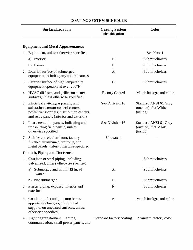
COATING SYSTEM SCHEDULE
Surface/Location Coating System
Identification
Color
Equipment and Metal Appurtenances
1. Equipment, unless otherwise specified See Note 1
a) Interior B Submit choices
b) Exterior B Submit choices
2. Exterior surface of submerged
equipment including any appurtenances
A Submit choices
3. Exterior surface of high temperature
equipment operable at over 200°F
D Submit choices
4. HVAC diffusers and grilles on coated
surfaces, unless otherwise specified
Factory Coated Match background color
5. Electrical switchgear panels, unit
substations, motor control centers,
power transformers, distribution centers,
and relay panels (interior and exterior)
See Division 16 Standard ANSI 61 Grey
(outside); flat White
(inside)
6. Instrumentation panels, indicating and
transmitting field panels, unless
otherwise specified
See Division 16 Standard ANSI 61 Grey
(outside); flat White
(inside)
7. Stainless steel, aluminum, factory
finished aluminum storefronts, and
metal panels, unless otherwise specified
Uncoated --
Conduit, Piping and Ductwork
1. Cast iron or steel piping, including
galvanized, unless otherwise specified
Submit choices
a) Submerged and within 12 in. of
water
A Submit choices
b) Not submerged B Submit choices
2. Plastic piping, exposed, interior and
exterior
N Submit choices
3. Conduit, outlet and junction boxes,
appurtenant hangers, clamps and
supports on uncoated surfaces, unless
otherwise specified
B Match background color
4. Lighting transformers, lighting,
communication, small power panels, and
Standard factory coating Standard factory color
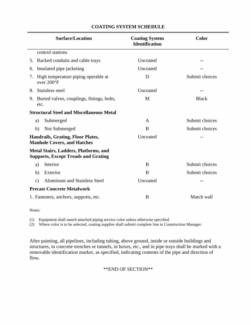
COATING SYSTEM SCHEDULE
Surface/Location Coating System
Identification
Color
control stations
5. Racked conduits and cable trays Uncoated --
6. Insulated pipe jacketing Uncoated --
7. High temperature piping operable at
over 200°F
D Submit choices
8. Stainless steel Uncoated --
9. Buried valves, couplings, fittings, bolts,
etc.
M Black
Structural Steel and Miscellaneous Metal
a) Submerged A Submit choices
b) Not Submerged B Submit choices
Handrails, Grating, Floor Plates,
Manhole Covers, and Hatches
Uncoated --
Metal Stairs, Ladders, Platforms, and
Supports, Except Treads and Grating
a) Interior B Submit choices
b) Exterior B Submit choices
c) Aluminum and Stainless Steel Uncoated --
Precast Concrete Metalwork
1. Fasteners, anchors, supports, etc. B Match wall
Notes:
(1) Equipment shall match attached piping service color unless otherwise specified.
(2) Where color is to be selected, coating supplier shall submit complete line to Construction Manager.
After painting, all pipelines, including tubing, above ground, inside or outside buildings and
structures, in concrete trenches or tunnels, in boxes, etc., and in pipe trays shall be marked with a
removable identification marker, as specified, indicating contents of the pipe and direction of
flow.
**END OF SECTION**
SECTION 09876
PLASTIC LINING FOR STRUCTURES
PART 1 - GENERAL
1.01 SCOPE
A. General
This section specifies material, design criteria, and labor required to furnish and install
polyvinylchloride (PVC) liner for poured in place reinforced concrete structures, and for
other unformed surfaces and reinforced concrete pipe where specified.
B. Application
Plastic lining shall be applied to interior exposed concrete surfaces of liquid containing
basins and channels, including the wet well of the sewage lift station. Plastic lining shall
cover all interior wall concrete surfaces from top to bottom of each wall and all other
surfaces indicated on the plans.
1.02 QUALITY ASSURANCE
D. References
The publications referred to hereinafter form a part of this specification to the extent
referenced. The publications are referred to in the text by the basic designation only.
The latest edition of referenced publications in effect at the time of the bid shall govern.
In case of conflict between the requirements of this section and the listed standards, the
requirements of this section shall prevail.
American Society for Testing and Materials (ASTM) Publications:
ASTM D412 Test Methods for Vulcanized Rubber and
Thermoplasic Rubbers and Thermoplasic
Elastomers in Tension
ASTM D2240 Test Methods for Rubber Property –
Durometer Hardness
B. Experience
All lining materials furnished under this section shall (1) be of a manufacturer who has
been regularly engaged in the design and manufacture of the lining for a minimum
period of 10 years, and (2) be demonstrated to the satisfaction of the Construction
Manager that the quality is equal to equipment made by those manufacturers specifically
named herein. The manufacturer shall have at least ten similar installations that have
been in service for at least 10 years.
The lining material furnished shall be warranted to be free from defects in materials and
workmanship for a period of 1 year from the date the material is put into service. Such
warranty shall cover all defects or failure of materials or workmanship that occur as
normal operation and service. In the event that the lining materials fail to perform as
specified during the warranty period, the lining materials’ manufacturer shall promptly
repair or replace the defective material without any cost to the City.
1.03 SUBMITTALS
The Contractor shall submit information in accordance with Section 01300,
SUBMITTALS, to substantiate compliance with this specification. In addition, the
following specific information shall be submitted.
A. Product Data
Manufacturer’s information and catalog data that include details and dimensions of
basic sheets and accessories, and composition of material used in the lining.
B. Test Results
1. Certified test results on initial physical property, chemical resistance tested
property and quality control test data shall be provided.
2. Certified shop test results that all sheets delivered to the construction site are free
of pinholes.
C. Certificates
1. Manufacturer’s certificate as specified in Part 3.03, Manufacturer’s Representative
Services, relating to the item(s) of this section.
2. Furnish a copy of manufacturer’s warranty.
1.04 SUPPLIER’S AND/OR MANUFACTURER’S SERVICES
The manufacturer shall provide the following services of technical representatives at the
jobsite relating to the item(s) specified in this section. The number of days and scope of
services indicated are minimum requirements not including travel time. Time for travel
and all associated expenses of the technical representative shall also be included at no
additional cost to the City.
3 labor days – Installation assistance and partial inspection.
The above services shall be at such times as requested by the City. See Section 01640,
SUPPLIER’S MANUFACTURER’S SERVICES DURING CONSTRUCTION,
COMMISSIONING AND TRAINING OF CITY PERSONNEL.
PART 2 - PRODUCTS
2.01 MATERIALS
Plastic lining for new concrete shall be Zebron, T-lock Amerplate as manufactured by
Ameron Corporation, Brea, California, or approved equal.
2.02 MATERIALS
A. PVC Sheets
The material used in both type of PVC linings, welding strips, and other accessory
items, shall be a combination of polyvinyl chloride resin, pigments and plasticizers,
specially compounded to remain flexible. Polyvinyl chloride resin shall constitute not
less than 99%, by weight, of the resin used in the formulation. Copolymer resins will not
be permitted. The sheet of the Type I lining shall be formed with T-rib extensions on
one face for casting with the concrete and shall not rely upon an adhesive bond for
adherence to the concrete surface.
The Type II lining sheets shall be formed with arrow-rib extensions on one face for
embedding into a layer of bonding material for adherence to the concrete surface.
Bonding shall be accomplished by an adhesive manufactured by the lining
manufacturer.
Both types of lining sheets shall be a nominal 0.065 inch in thickness. Locking
extensions of the same material as that of the lining shall be integrally extruded with the
sheet. Locking extensions of Type I lining sheets shall be approximately 2.5 inches apart
and shall be at least 0.375 inch high. Locking extensions of the Type II lining sheets
shall be approximately 2 inches apart and at least 1/4 inch high. Joint strips and welding
strips shall have the same corrosion resistance as the sheet lining material but shall not
have locking extensions. Lining sheets, including locking extensions, all joint, corner,
and welding strips, shall be free of cracks, cleavages, or other defects adversely
affecting the protective characteristics of the material. Sheets shall be shop tested for
pinholes using an electrical spark tester set between 18,000 and 22,000 volts. Any holes
shall be repaired and retested. All lining shall have good impact resistance and shall
have an elongation sufficient to bridge up to 1/4-inch settling cracks which may occur in
joints after installation without damage to the lining sheets. The lining shall be
repairable at any time during the life of the structure. The nominal size of each lining
sheet shall be 48 inches wide and 24 feet long.
B. Bonding Materials
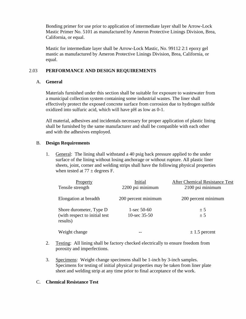
Bonding primer for use prior to application of intermediate layer shall be Arrow-Lock
Mastic Primer No. 5101 as manufactured by Ameron Protective Linings Division, Brea,
California, or equal.
Mastic for intermediate layer shall be Arrow-Lock Mastic, No. 99112 2:1 epoxy gel
mastic as manufactured by Ameron Protective Linings Division, Brea, California, or
equal.
2.03 PERFORMANCE AND DESIGN REQUIREMENTS
A. General
Materials furnished under this section shall be suitable for exposure to wastewater from
a municipal collection system containing some industrial wastes. The liner shall
effectively protect the exposed concrete surface from corrosion due to hydrogen sulfide
oxidized into sulfuric acid, which will have pH as low as 0-1.
All material, adhesives and incidentals necessary for proper application of plastic lining
shall be furnished by the same manufacturer and shall be compatible with each other
and with the adhesives employed.
B. Design Requirements
1. General: The lining shall withstand a 40 psig back pressure applied to the under
surface of the lining without losing anchorage or without rupture. All plastic liner
sheets, joint, corner and welding strips shall have the following physical properties
when tested at 77 ± degrees F.
Property Initial After Chemical Resistance Test
Tensile strength 2200 psi minimum 2100 psi minimum
Elongation at breadth 200 percent minimum 200 percent minimum
Shore durometer, Type D
(with respect to initial test
results)
1-sec 50-60
10-sec 35-50
± 5
± 5
Weight change -- ± 1.5 percent
2. Testing: All lining shall be factory checked electrically to ensure freedom from
porosity and imperfections.
3. Specimens: Weight change specimens shall be 1-inch by 3-inch samples.
Specimens for testing of initial physical properties may be taken from liner plate
sheet and welding strip at any time prior to final acceptance of the work.
C. Chemical Resistance Test
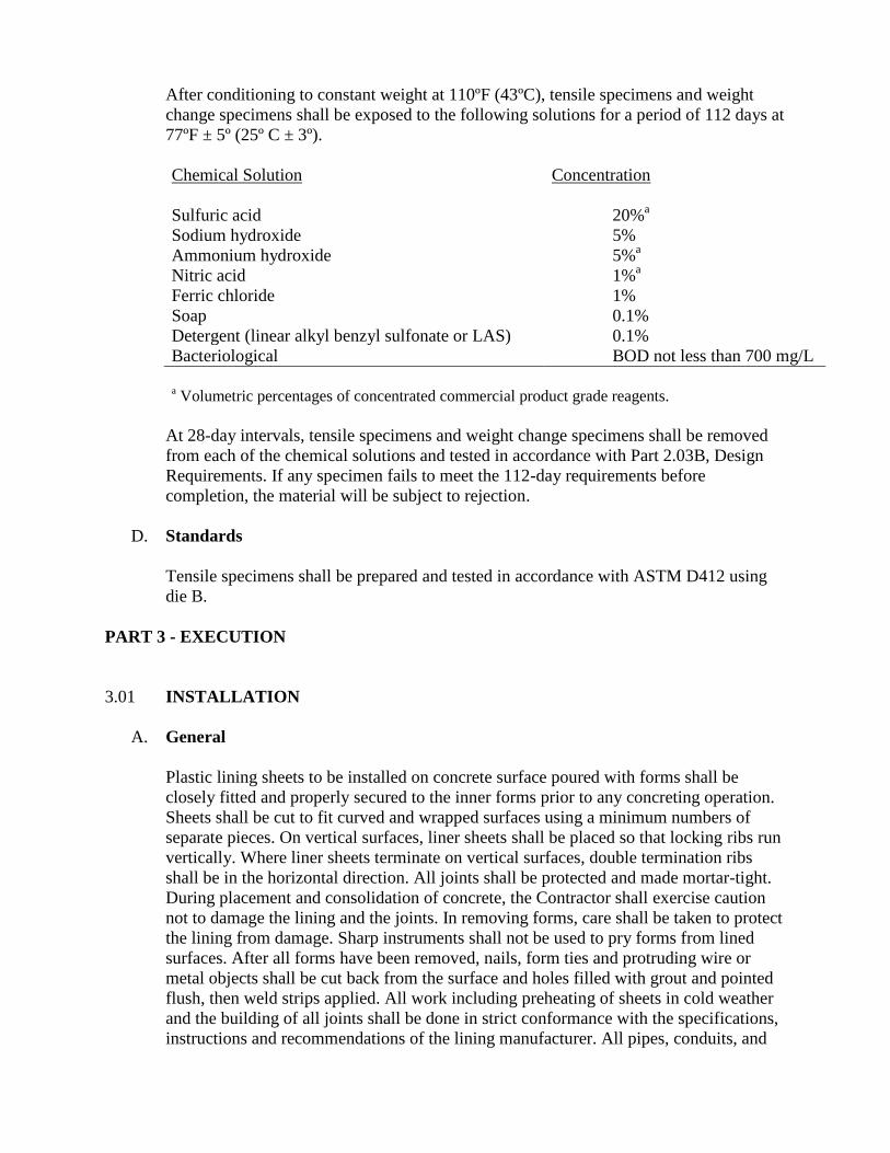
After conditioning to constant weight at 110ºF (43ºC), tensile specimens and weight
change specimens shall be exposed to the following solutions for a period of 112 days at
77ºF ± 5º (25º C ± 3º).
Chemical Solution Concentration
Sulfuric acid 20%a
Sodium hydroxide 5%
Ammonium hydroxide 5%a
Nitric acid 1%a
Ferric chloride 1%
Soap 0.1%
Detergent (linear alkyl benzyl sulfonate or LAS) 0.1%
Bacteriological BOD not less than 700 mg/L
a Volumetric percentages of concentrated commercial product grade reagents.
At 28-day intervals, tensile specimens and weight change specimens shall be removed
from each of the chemical solutions and tested in accordance with Part 2.03B, Design
Requirements. If any specimen fails to meet the 112-day requirements before
completion, the material will be subject to rejection.
D. Standards
Tensile specimens shall be prepared and tested in accordance with ASTM D412 using
die B.
PART 3 - EXECUTION
3.01 INSTALLATION
A. General
Plastic lining sheets to be installed on concrete surface poured with forms shall be
closely fitted and properly secured to the inner forms prior to any concreting operation.
Sheets shall be cut to fit curved and wrapped surfaces using a minimum numbers of
separate pieces. On vertical surfaces, liner sheets shall be placed so that locking ribs run
vertically. Where liner sheets terminate on vertical surfaces, double termination ribs
shall be in the horizontal direction. All joints shall be protected and made mortar-tight.
During placement and consolidation of concrete, the Contractor shall exercise caution
not to damage the lining and the joints. In removing forms, care shall be taken to protect
the lining from damage. Sharp instruments shall not be used to pry forms from lined
surfaces. After all forms have been removed, nails, form ties and protruding wire or
metal objects shall be cut back from the surface and holes filled with grout and pointed
flush, then weld strips applied. All work including preheating of sheets in cold weather
and the building of all joints shall be done in strict conformance with the specifications,
instructions and recommendations of the lining manufacturer. All pipes, conduits, and
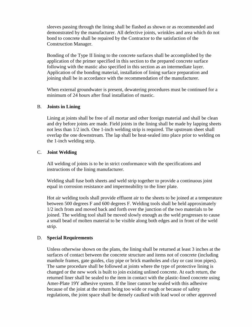
sleeves passing through the lining shall be flashed as shown or as recommended and
demonstrated by the manufacturer. All defective joints, wrinkles and area which do not
bond to concrete shall be repaired by the Contractor to the satisfaction of the
Construction Manager.
Bonding of the Type II lining to the concrete surfaces shall be accomplished by the
application of the primer specified in this section to the prepared concrete surface
following with the mastic also specified in this section as an intermediate layer.
Application of the bonding material, installation of lining surface preparation and
joining shall be in accordance with the recommendation of the manufacturer.
When external groundwater is present, dewatering procedures must be continued for a
minimum of 24 hours after final installation of mastic.
B. Joints in Lining
Lining at joints shall be free of all mortar and other foreign material and shall be clean
and dry before joints are made. Field joints in the lining shall be made by lapping sheets
not less than 1/2 inch. One 1-inch welding strip is required. The upstream sheet shall
overlap the one downstream. The lap shall be heat-sealed into place prior to welding on
the 1-inch welding strip.
C. Joint Welding
All welding of joints is to be in strict conformance with the specifications and
instructions of the lining manufacturer.
Welding shall fuse both sheets and weld strip together to provide a continuous joint
equal in corrosion resistance and impermeability to the liner plate.
Hot air welding tools shall provide effluent air to the sheets to be joined at a temperature
between 500 degrees F and 600 degrees F. Welding tools shall be held approximately
1/2 inch from and moved back and forth over the junction of the two materials to be
joined. The welding tool shall be moved slowly enough as the weld progresses to cause
a small bead of molten material to be visible along both edges and in front of the weld
strip.
D. Special Requirements
Unless otherwise shown on the plans, the lining shall be returned at least 3 inches at the
surfaces of contact between the concrete structure and items not of concrete (including
manhole frames, gate guides, clay pipe or brick manholes and clay or cast iron pipes).
The same procedure shall be followed at joints where the type of protective lining is
changed or the new work is built to join existing unlined concrete. At each return, the
returned liner shall be sealed to the item in contact with the plastic-lined concrete using
Amer-Plate 19Y adhesive system. If the liner cannot be sealed with this adhesive
because of the joint at the return being too wide or rough or because of safety
regulations, the joint space shall be densely caulked with lead wool or other approved
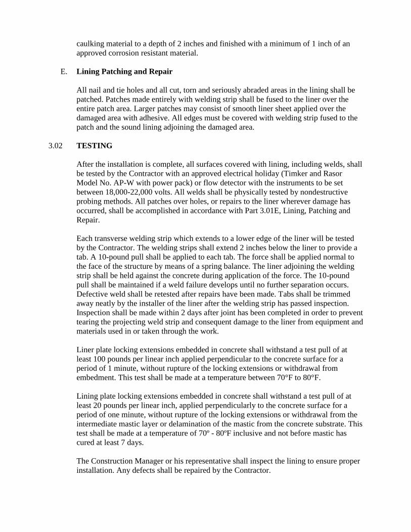
caulking material to a depth of 2 inches and finished with a minimum of 1 inch of an
approved corrosion resistant material.
E. Lining Patching and Repair
All nail and tie holes and all cut, torn and seriously abraded areas in the lining shall be
patched. Patches made entirely with welding strip shall be fused to the liner over the
entire patch area. Larger patches may consist of smooth liner sheet applied over the
damaged area with adhesive. All edges must be covered with welding strip fused to the
patch and the sound lining adjoining the damaged area.
3.02 TESTING
After the installation is complete, all surfaces covered with lining, including welds, shall
be tested by the Contractor with an approved electrical holiday (Timker and Rasor
Model No. AP-W with power pack) or flow detector with the instruments to be set
between 18,000-22,000 volts. All welds shall be physically tested by nondestructive
probing methods. All patches over holes, or repairs to the liner wherever damage has
occurred, shall be accomplished in accordance with Part 3.01E, Lining, Patching and
Repair.
Each transverse welding strip which extends to a lower edge of the liner will be tested
by the Contractor. The welding strips shall extend 2 inches below the liner to provide a
tab. A 10-pound pull shall be applied to each tab. The force shall be applied normal to
the face of the structure by means of a spring balance. The liner adjoining the welding
strip shall be held against the concrete during application of the force. The 10-pound
pull shall be maintained if a weld failure develops until no further separation occurs.
Defective weld shall be retested after repairs have been made. Tabs shall be trimmed
away neatly by the installer of the liner after the welding strip has passed inspection.
Inspection shall be made within 2 days after joint has been completed in order to prevent
tearing the projecting weld strip and consequent damage to the liner from equipment and
materials used in or taken through the work.
Liner plate locking extensions embedded in concrete shall withstand a test pull of at
least 100 pounds per linear inch applied perpendicular to the concrete surface for a
period of 1 minute, without rupture of the locking extensions or withdrawal from
embedment. This test shall be made at a temperature between 70°F to 80°F.
Lining plate locking extensions embedded in concrete shall withstand a test pull of at
least 20 pounds per linear inch, applied perpendicularly to the concrete surface for a
period of one minute, without rupture of the locking extensions or withdrawal from the
intermediate mastic layer or delamination of the mastic from the concrete substrate. This
test shall be made at a temperature of 70º - 80ºF inclusive and not before mastic has
cured at least 7 days.
The Construction Manager or his representative shall inspect the lining to ensure proper
installation. Any defects shall be repaired by the Contractor.
3.03 MANUFACTURER’S REPRESENTATIVE SERVICES
The lining manufacturer or his/her representative in cooperation with the Construction
Manager shall inspect the installation of the lining prior to commissioning of the
structure and shall direct the necessary repair to the lining for satisfactory operation. The
manufacturer shall also be responsible for instructing the City’s personnel in the
maintenance of the lining. The manufacturer or his/her representative shall certify the
correctness of the installation in accordance with Section 01640, SUPPLIER’S/
MANUFACTURER’S SERVICES DURING CONSTRUCTION, COMMISSIONING,
AND TRAINING OF CITY’S PERSONNEL.
**END OF SECTION**
SECTION 11223 – SUBMERSIBLE CHOPPER PUMPING SYSTEMS
PART 1 GENERAL
2.01.1.1 DESCRIPTION
The vendor shall furnish THREE (3) submersible wet pit chopper pump and all appurtenances
as specified. Only two (2) shall be installed. The pumps shall be specifically designed to pump
waste solids at heavy consistencies without plugging or dewatering of the solids. Materials shall
be chopped/macerated and conditioned by the pump as an integral part of the pumping action.
The pump must have demonstrated the ability to chop through and pump high concentrations of
solids such as plastics, heavy rags, grease and hair balls, wood, paper products and stringy
materials without plugging, both in tests and field applications.
2.01.1.2 QUALITY ASSURANCE AND PERFORMANCE AFFIDAVIT
The contractor shall submit manufacturer's standard warranty and a performance affidavit for
equipment to be furnished in accordance with this section. The warranty for workmanship and
materials shall be manufacturer's standard for 1 year from startup, not to exceed 18 months from
factory shipment. In the performance affidavit, the manufacturer must certify to the Contractor
and the Owner, that the Contract Documents have been examined, and that the equipment will
meet in every way the performance requirements set forth in the Contract Documents for the
application specified. Shop drawings will not be reviewed prior to the receipt by the Engineer
of an acceptable performance affidavit. The performance affidavit must be signed by an officer
of the company manufacturing the equipment, and witnessed by a notary public. The
performance affidavit must include a statement that the equipment will not clog or bind on solids
typically found in the application set forth.
PART 2 PRODUCTS
2.1 APPROVED MANUFACTURER
A. Pump shall be Model SE4T as manufactured by Vaughan Co., Inc. or approved equal.
2.2 SERVICE CONDITIONS
The pumps specified in this section will pump municipal wastewater using the following design
flow criteria:
GPM: 850
TDH: 30 Feet
HP: 15
RPM: 1160
2.3 PUMP CONSTRUCTION
A. Casing and Back Pull-Out Plate: The pump casing shall be of volute design, spiraling
outward to the 125 lb. flanged centerline discharge. Back pull-out design shall
incorporate jacking bolts for accurate adjustment of impeller-to-cutter bar clearance.
Casing & backplate shall be ductile cast iron with all water passages to be smooth, and
free of blowholes and imperfections for good flow characteristics. A pressure tap shall be
included on or near the discharge flange. Backplate shall include a replaceable Rockwell
C 60 steel cutter adjustable for 0.005-0.015" clearance to cut against the rotating impeller
pumpout vanes for removing fiber and debris.
B. Impeller: Shall be semi-open type with pump out vanes to reduce seal area pressure.
Chopping/maceration of materials shall be accomplished by the action of the cupped and
sharpened leading edges of the impeller blades moving across the cutter bar at the intake
openings, with a maximum set clearance between the impeller and cutter bar of 0.015-
0.025” cold. Impeller shall be cast alloy steel heat treated to minimum Rockwell C 60
and dynamically balanced. The impeller shall be keyed to the shaft and shall have no
axial adjustments and no set screws.
C. Cutter Bar Plate: Shall be recessed into the pump bowl and shall contain at least 2 shear
bars extending diametrically across the intake opening to within 0.010-0.020” of the
rotating cutter nut tooth, for the purpose of preventing intake opening blockage and
wrapping of debris at the shaft area. Chopper pumps utilizing individually mounted shear
bars shall not be acceptable. Cutter bar shall be alloy steel heat-treated to minimum
Rockwell C 60.
D. Cutter Nut: The impeller shall be secured to the shaft using a cutter nut, designed to cut
stringy materials and prevent binding using a raised, rotating cutter tooth. The cutter nut
shall be cast steel heat treated to minimum Rockwell C 60.
E. Upper Cutter: Shall be threaded into the back pull-out adapter plate behind the impeller,
designed to cut against the pump-out vanes and the impeller hub, reducing and removing
stringy materials from the mechanical seal area. Upper cutter shall be cast steel heat
treated to minimum Rockwell C 60. The upper cutter teeth are positioned as closely as
possible to the center of shaft rotation to minimize cutting torque and nuisance motor
tripping. The ratio of upper cutter cutting diameter to shaft diameter in the upper cutter
area of the pump shall be 3.0 or less.
F. Shafting: Pump shafting shall be heat-treated alloy steel. The pump shaft shall directly
couple to the motor shaft, with a bolt and keyway.
G. Stainless Steel Nameplates: Shall be attached to the pump and drive motor giving the
manufacturer’s model and serial number, rated capacity, head, speed and all pertinent
data.
2.4 SUBMERSIBLE ELECTRIC MOTOR
Submersible Electric Motor: The submersible motor shall be U/L LISTED EXPLOSION
PROOF for Class 1, Group D, Division 1 hazardous locations, rated at 7.5 HP, 1750 RPM, 460
Volts, 60 Hertz and 3 phase, with a 1.15 service factor and Class F insulation. Motor shall be
equipped with tandem independently mounted mechanical seals in oil bath and with dual
moisture sensing probes. The inner and outer seals shall be separated by an oil-filled chamber.
Double-seal (back to back) configurations are not acceptable due to the potential for failure of
both seals as a result of lodged solids. The oil chamber shall act as a barrier to trap moisture and
provide sufficient time for a planned shutdown. The oil shall also provide lubrication to the
internal seal. The inner seal shall be a standard UL listed John Crane Type 21 or equal, with
carbon rotating face and ceramic stationary face. The outer seal construction shall be designed
for easy replacement. Outer mechanical seal shall be 316 stainless steel pusher type with silicon
or tungsten carbide faces. Seal shall be positively driven by set screws. Elastomers shall be of
Viton®. Motor shall include two normally closed automatic resetting thermostats connected in
series and imbedded in adjoining phases. Motor frame shall be cast iron, and all hardware and
shaft shall be stainless steel.
2.5 SPARK PROOF GUIDE RAIL BRACKET
Provide a non-sparking guide rail bracket for adapting the pumps to existing guide rail system.
Manufacturers who require demolition of the existing guide rail system are not acceptable.
2.6 SURFACE PREPARATION
Solvent wash, coat with minimum 3 MDFT epoxy.
10-2.02 WETWELL POLYURETHANE LINING SPECIFICATION
A. GENERAL
The existing sewer wet well at the wastewater treatment plant shall be polyurethane
lined. Polyurethane lining shall be applied and approved before sewer is put into
service.
The work shall consist of preparing all interior concrete surfaces of the wet well
(excluding the floor) application of epoxy primer, top-coated with polyurethane lining
and all incidentals necessary to complete the work contained in these technical
provisions.
1. The Contractor shall furnish all labor, material, and equipment necessary for the
preparation of surfaces, application of lining, safety procedures, protection of
existing surfaces and equipment, and cleanup.
2. At the option of the Engineer, the Contractor shall demonstrate the material on a
sample area, which is representative of a job site application. When approved,
the sample area shall serve as a standard for all further work.
B. CLEANING
All concrete surfaces to be lined shall be abrasive grit blasted to remove all laitance and
other deleterious material to obtain a clean, sound substrate with a 60 mil profile and a
suitable bonding surface for the polyurethane liner.
All debris produced from the abrasive grit blasting operation shall be removed from the
structure prior to coating. The concrete surfaces shall be clean, free of dust and dry
prior to application of the prime coating.
C. PRIMER AND LINING MATERIALS
Prior to application of the polyurethane topcoat, all surfaces shall receive a 1 – 3 mil
thickness of a 100% solids nonsolvented, moisture-tolerant, low temperature cure,
epoxy primer as is manufactured by Zebron Corporation, Anaheim, CA, or equal. The
primer materials shall be 100% solids, moisture tolerant epoxy capable of spray
application to 5 mils thickness in one continuous coat.
The lining material shall be a plural-component, 3 - 1 mix ratio, 100% solid,
nonsolvented hybrid polyurethane coating with a shore “D” hardness of 57 at 77
degrees Fahrenheit such as Zebron #386 as manufactured by Zebron Corporation,
Anaheim, CA. The material shall be the high-build type capable of application
thickness, as specified, without runs or sags and shall be capable of passing ASTM D-
1737 for flexibility using cylinder mandrel of 0.5 inch (12.7 millimeter). The flash
point of the fluid mixture shall be 450 degrees Fahrenheit open Zahn cup.
The coating material shall meet the following resistive specifications:
Solution Concentration
Acetic Acid 5%
Sulfuric Acid 20%
Sodium Hydroxide 5%
Ammonium Hydroxide 5%
Nitric Acid 1%
Ferric Acid 1%
Soap 0.1%
Detergent (Linear Alkyl Benzyl Sulfonite or LAS) 0.1%
Bacteriological BOD not less than700 PPM
Petroleum Oils and Greases N/A
Vegetable and Animal Oils N/A
The color shall be white or cream. The complete coating shall be impermeable to sewer
gases and liquids and nonconductive to bacterial or fungus growth. The lining shall be
capable of repair at any time during its life.
D. LINING APPLICATION
The lining application shall be performed only by workers approved by the
manufacturer as trained and experienced with the specified material. The lining shall be
applied by high-pressure, airless equipment approved by the lining manufacturer. The
equipment shall be in good working order to ensure correct proportioning and mixing of
components.
The polyurethane lining application shall take place after the gunite/mortar has cured
for a minimum of 1 hour at 55.F and shall be applied to all exposed concrete surfaces
down to the low flow water level and up to the base of the ring and cover.
Prior to the polyurethane application, the wet well surfaces shall be primed with the
epoxy primer to a thickness of 1 – 3 mils. The polyurethane lining is installed
immediately after the epoxy primer application or up to 24 hours after the epoxy primer
application. The polyurethane lining shall be applied to a 125-mil thickness.
During the application, the contractor shall take wet gauge film thickness readings as
required to ensure correct lining thickness. The polyurethane lining shall be uniform in
color, fully cured and free of pinholes, surface imperfections and blisters. All areas in
question shall be removed and reworked and patched.
Application of the lining shall not take place when exposed to rain, fog or high winds. It
is the contractor’s responsibility to insure protection of the work for the above-
mentioned conditions.
E. REPAIR METHODS
All pinholes in the protective lining shall be highlighted with black indelible ink for the
purpose of identifying them for the repair process. Using the pinhole as a centerpoint,
the area 150 mm (6 inches) around the pinhole must be abraded with a 60-grit paper or
“equivalent”. Abraded surfaces are then cleaned, primed and topcoated Zebron #385
handmix. Blisters, uncured lining, and surface imperfections shall be completely
removed and the areas recoated with epoxy primer and polyurethane lining to a point
150mm beyond the repair areas at a minimum thickness of 100 mils. Where
imperfections exceed an area of one square foot, the contractor shall repair as stated
above using the Zebron #386 spray applied polyurethane.
MATERIAL SUBSTITUTION
Materials specified are those that have been evaluated for the specific service.
Elastomeric urethane products of Zebron Corporation or equal are listed to establish a
standard of quality. Standard products of manufacturers other than those specified will
be accepted when it is proved to the satisfaction of the Engineer they are equal in
composition, durability, usefulness, and convenience for the purpose intended.
Substitution will be considered provided the following minimum conditions are met:
1. The proposed lining system shall have a dry film thickness equal to or greater
than that of the specified system.
2. The proposed lining system shall employ an equal number of coats.
3. The proposed lining system shall employ coating of the same generic type.
4. The proposed lining system shall have been successfully used in 10 similar
projects, all at least 3 years old, where the same proposed lining has been applied
to similar exposure and application.
5. All requests for substitution shall carry full descriptive literature and directions
for application, along with complete information generic type, non-volatile
content by volume.
6. In the above-mentioned data, if it appears to be in order, the Engineer may
require that the Contractor provide certified laboratory data sheets showing the
results of complete spectrographic and durability tests performed on the
proposed substitute. Tests shall be performed by an independent testing
laboratory approved by the Engineer, and all costs incurred in the testing
program shall be borne by the Contractor. The Engineer shall be sole and final
judge of the acceptability of any proposed substitution. Requests for substitution
must be approved in writing.
7. The manufacturer of the elastomeric polyurethane shall warrant its lining for five
years against any type of failure due to defect in material and application. A
copy of the warranty shall be submitted.
F. ACCEPTANCE OF WORK
After the lining work has been completed, the work shall be visually inspected by the
Contractor in the presence of the Engineer.
**END OF SECTION**
SECTION 15070
PLASTIC PIPE
PART 1 - GENERAL
1.01 SCOPE
This section specifies polyvinyl chloride and polypropylene pipe and fittings.
A. Pipe Designations
For use in Section 15060, PIPING SYSTEMS and in this section, the following plastic
pipe designation is defined:
Designation Definition
PVC Polyvinyl Chloride
PP Polypropylene
1.02 QUALITY ASSURANCE
A. References
The publications referred to hereinafter form a part of this specifications to the extent
referenced. The publications are referred to in the text by the basic designation only.
The latest edition of referenced publications in effect at the time of the bid shall govern.
In case of conflict between the requirements of this section and the listed standards, the
requirements of this section shall prevail.
American Society for Testing Materials (ASTM) Publications:
ASTM A536 Ductile Iron Castings
ASTM D1784 Rigid Poly(Vinyl Chloride) (PVC) Compounds and Chlorinated
Poly(Vinyl Chloride) (CPVC) Compounds
ASTM D1785 Poly(Vinyl Chloride) (PVC) Plastic Pipe, Schedules 40, 80,
and 120
ASTM D2241 Poly(Vinyl Chloride) (PVC) Pressure-Rated Pipe (SDR series)
ASTM D2321 Underground Installation of Flexible Thermoplastic Sewer
Pipe
ASTM D2464 Threaded Poly(Vinyl Chloride) (PVC) Plastic Pipe Fittings,
Schedule 80
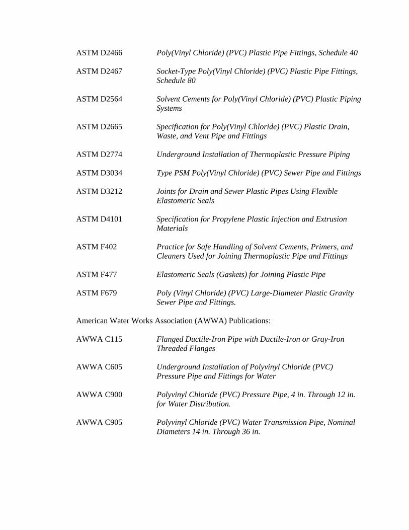
ASTM D2466 Poly(Vinyl Chloride) (PVC) Plastic Pipe Fittings, Schedule 40
ASTM D2467 Socket-Type Poly(Vinyl Chloride) (PVC) Plastic Pipe Fittings,
Schedule 80
ASTM D2564 Solvent Cements for Poly(Vinyl Chloride) (PVC) Plastic Piping
Systems
ASTM D2665 Specification for Poly(Vinyl Chloride) (PVC) Plastic Drain,
Waste, and Vent Pipe and Fittings
ASTM D2774 Underground Installation of Thermoplastic Pressure Piping
ASTM D3034 Type PSM Poly(Vinyl Chloride) (PVC) Sewer Pipe and Fittings
ASTM D3212 Joints for Drain and Sewer Plastic Pipes Using Flexible
Elastomeric Seals
ASTM D4101 Specification for Propylene Plastic Injection and Extrusion
Materials
ASTM F402 Practice for Safe Handling of Solvent Cements, Primers, and
Cleaners Used for Joining Thermoplastic Pipe and Fittings
ASTM F477 Elastomeric Seals (Gaskets) for Joining Plastic Pipe
ASTM F679 Poly (Vinyl Chloride) (PVC) Large-Diameter Plastic Gravity
Sewer Pipe and Fittings.
American Water Works Association (AWWA) Publications:
AWWA C115 Flanged Ductile-Iron Pipe with Ductile-Iron or Gray-Iron
Threaded Flanges
AWWA C605 Underground Installation of Polyvinyl Chloride (PVC)
Pressure Pipe and Fittings for Water
AWWA C900 Polyvinyl Chloride (PVC) Pressure Pipe, 4 in. Through 12 in.
for Water Distribution.
AWWA C905 Polyvinyl Chloride (PVC) Water Transmission Pipe, Nominal
Diameters 14 in. Through 36 in.
1.03 SUBMITTALS
The Contractor shall submit information in accordance with Section 01300,
SUBMITTALS, to substantiate compliance with this specification. In addition, the
following specific information shall be submitted.
A. Shop Drawings
Contractor's layout drawings.
B. Manufacturer's Data
Manufacturer's name and catalog number of all piping system products.
C. Certificates
Manufacturer's certificates of compliance with the specified standards.
D. Specification Compliance
A copy of this specification section, with addenda updates, and all referenced sections,
with addenda updates, with each paragraph check marked to show specification
compliance or marked to show deviation.
A copy of the portion of Section 01300, SUBMITTALS that applies to this submittal
shall be neatly and clearly marked by a check mark or circled indicating it has been
reviewed and, as a minimum, complies with each requirement outlined or marked to
show any deviation.
1.04 DEFINITIONS
Terms used in Section 15060, PIPING SYSTEMS and elsewhere in Division 15 are
defined as follows:
1. Pressure Terms:
a. Maximum: The greatest continuous pressure at which the piping system
operates.
b. Test: The hydrostatic pressure used to determine system acceptance.
2. Piping Exposure Terms:
a. Buried: Pipe, which may be insulated, that is located below grade and in contact
with backfill material; or pipe, which may be insulated, that is located below
grade and is concrete encased.
b. Not Buried: Pipe that does not meet the definition of buried pipe.
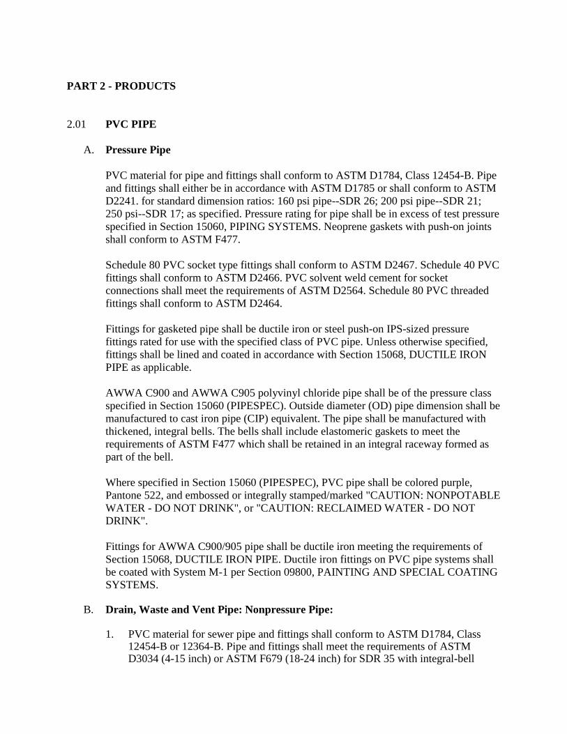
PART 2 - PRODUCTS
2.01 PVC PIPE
A. Pressure Pipe
PVC material for pipe and fittings shall conform to ASTM D1784, Class 12454-B. Pipe
and fittings shall either be in accordance with ASTM D1785 or shall conform to ASTM
D2241. for standard dimension ratios: 160 psi pipe--SDR 26; 200 psi pipe--SDR 21;
250 psi--SDR 17; as specified. Pressure rating for pipe shall be in excess of test pressure
specified in Section 15060, PIPING SYSTEMS. Neoprene gaskets with push-on joints
shall conform to ASTM F477.
Schedule 80 PVC socket type fittings shall conform to ASTM D2467. Schedule 40 PVC
fittings shall conform to ASTM D2466. PVC solvent weld cement for socket
connections shall meet the requirements of ASTM D2564. Schedule 80 PVC threaded
fittings shall conform to ASTM D2464.
Fittings for gasketed pipe shall be ductile iron or steel push-on IPS-sized pressure
fittings rated for use with the specified class of PVC pipe. Unless otherwise specified,
fittings shall be lined and coated in accordance with Section 15068, DUCTILE IRON
PIPE as applicable.
AWWA C900 and AWWA C905 polyvinyl chloride pipe shall be of the pressure class
specified in Section 15060 (PIPESPEC). Outside diameter (OD) pipe dimension shall be
manufactured to cast iron pipe (CIP) equivalent. The pipe shall be manufactured with
thickened, integral bells. The bells shall include elastomeric gaskets to meet the
requirements of ASTM F477 which shall be retained in an integral raceway formed as
part of the bell.
Where specified in Section 15060 (PIPESPEC), PVC pipe shall be colored purple,
Pantone 522, and embossed or integrally stamped/marked "CAUTION: NONPOTABLE
WATER - DO NOT DRINK", or "CAUTION: RECLAIMED WATER - DO NOT
DRINK".
Fittings for AWWA C900/905 pipe shall be ductile iron meeting the requirements of
Section 15068, DUCTILE IRON PIPE. Ductile iron fittings on PVC pipe systems shall
be coated with System M-1 per Section 09800, PAINTING AND SPECIAL COATING
SYSTEMS. B. Drain, Waste and Vent Pipe: Nonpressure Pipe: 1. PVC material for sewer pipe and fittings shall conform to ASTM D1784, Class
12454-B or 12364-B. Pipe and fittings shall meet the requirements of ASTM D3034 (4-15 inch) or ASTM F679 (18-24 inch) for SDR 35 with integral-bell
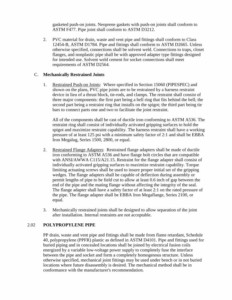
gasketed push-on joints. Neoprene gaskets with push-on joints shall conform to ASTM F477. Pipe joint shall conform to ASTM D3212.
2. PVC material for drain, waste and vent pipe and fittings shall conform to Class
12454-B, ASTM D1784. Pipe and fittings shall conform to ASTM D2665. Unless otherwise specified, connections shall be solvent weld. Connections to traps, closet flanges, and nonplastic pipe shall be with approved adapter type fittings designed for intended use. Solvent weld cement for socket connections shall meet requirements of ASTM D2564.
C. Mechanically Restrained Joints 1. Restrained Push-on Joints: Where specified in Section 15060 (PIPESPEC) and
shown on the plans, PVC pipe joints are to be restrained by a harness restraint device in lieu of a thrust block, tie-rods, and clamps. The restraint shall consist of three major components: the first part being a bell ring that fits behind the bell; the second part being a restraint ring that installs on the spigot; the third part being tie bars to connect parts one and two to facilitate the joint restraint.
All of the components shall be cast of ductile iron conforming to ASTM A536. The
restraint ring shall consist of individually activated gripping surfaces to hold the spigot and maximize restraint capability. The harness restraint shall have a working pressure of at least 125 psi with a minimum safety factor of 2:1 and shall be EBBA Iron Megalug, Series 1500, 2800, or equal.
2. Restrained Flange Adapters: Restrained flange adapters shall be made of ductile
iron conforming to ASTM A536 and have flange bolt circles that are compatible with ANSI/AWWA C115/A21.15. Restraint for the flange adapter shall consist of individually activated gripping surfaces to maximize restraint capability. Torque limiting actuating screws shall be used to insure proper initial set of the gripping wedges. The flange adapters shall be capable of deflection during assembly or permit lengths of pipe to be field cut to allow at least 0.6 inch of gap between the end of the pipe and the mating flange without affecting the integrity of the seal. The flange adapter shall have a safety factor of at least 2:1 on the rated pressure of the pipe. The flange adapter shall be EBBA Iron Megaflange, Series 2100, or equal.
3. Mechanically restrained joints shall be designed to allow separation of the joint
after installation. Internal restraints are not acceptable. 2.02 POLYPROPYLENE PIPE PP drain, waste and vent pipe and fittings shall be made from flame retardant, Schedule
40, polypropylene (PPFR) plastic as defined in ASTM D4101. Pipe and fittings used for buried piping and in concealed locations shall be joined by electrical fusion coils energized by a variable low-voltage power supply to completely fuse the interface between the pipe and socket and form a completely homogenous structure. Unless otherwise specified, mechanical joint fittings may be used under bench or in not buried locations where future disassembly is desired. The mechanical method shall be in conformance with the manufacturer's recommendation.
PART 3 - EXECUTION 3.01 INSTALLATION A. General Plastic piping shall be installed in accordance with AWWA C605, ASTM D2321, or
ASTM D2774, as applicable, and as shown on the plans. B. Support And Anchorage Support and anchorage shall be as shown on the plans and as specified in Section 15140,
PIPING SUPPORTS. PVC pipe 3 inches in diameter and smaller shall be joined by means of socket fittings
and solvent welding in conformance with ASTM F402. Unless otherwise specified, PVC pipe 4 inches in diameter and greater shall be joined by means of gasketed push-on joints and steel (IPS size) or ductile iron (CIOD size) push-on or mechanical joint fittings. Fittings shall be lined and coated where specified in Section 15060, PIPING SYSTEMS.
C. Connections Connections to different types of pipe shall be by means of flanges, specified adapters or
transition fittings. Where sleeve type couplings are used, both shall be uniformly torqued in accordance with pipe manufacturer's recommendation. Foreign material shall be removed from the pipe interior prior to assembly.
Mechanical joint restraints shall be installed in accordance with the manufacturer's
instructions. 3.02 TESTING Hydrostatic testing of plastic piping shall be as specified in Section 7 of AWWA C605
except that test pressures and allowable leakage shall be as listed in Section 15060, PIPING SYSTEMS.
**END OF SECTION**
SECTION 15101
GATE VALVES
PART 1 - GENERAL
1.01 SCOPE
This section specifies iron body gate valves. Refer to Section 11000, GENERAL
REQUIREMENTS FOR EQUIPMENT, for additional requirements that apply.
1.02 QUALITY ASSURANCE
A. References
The publications referred to hereinafter form a part of this specifications to the extent
referenced. The publications are referred to in the text by the basic designation only.
The latest edition of referenced publications in effect at the time of the bid shall govern.
In case of conflict between the requirements of this section and the listed standards, the
requirements of this section shall prevail.
American National Standards Institute (ANSI) Publications:
ANSI B16.1 Cast Iron Pipe Flanges and Flanged Fittings
American Society for Testing and Materials (ASTM) Publications:
ASTM A126 Gray Iron Castings for Valves, Flanges and Pipe Fittings
ASTM A536 Ductile Iron Castings
ASTM B138 Manganese Bronze Rod, Bar and Shapes
ASTM B763 Copper Alloy Sand Castings for Valve Application
American Water Works Association (AWWA) Publications:
AWWA C509 Resilient-Seated Gate Valves for Water Supply Service
AWWA C515
AWWA C550 Protective Epoxy Interior Coatings for Valves and Hydrants
1.03 SUBMITTALS
The Contractor shall submit information in accordance with Section 01300,
SUBMITTALS, to substantiate compliance with this specification. In addition, the
following specific information shall be submitted:
A. Compliance Affidavits
Affidavits of compliance, as required by AWWA C509.
B. Test Results
Hydrostatic test results.
C. Manufacturer's Data
Manufacturer’s catalog cut with highlighting to shown compliance with specified
features.
D. Specification Compliance
A copy of this specification section, with addenda updates, and all referenced sections,
with addenda updates, with each paragraph check marked to show specification
compliance or marked to show deviation.
A copy of the portion of Section 01300, SUBMITTALS that applies to this submittal
shall be neatly and clearly marked by a check mark or circled indicating it has been
reviewed and, as a minimum, complies with each requirement outlined or marked to
show any deviation.
1.04 OPERATION AND MAINTENANCE INSTRUCTIONS
Submit operation and maintenance instructions in accordance with Section 01730,
OPERATING AND MAINTENANCE INFORMATION. A copy of Section 01730 with
each paragraph check marked to show compliance shall be submitted. O&M instructions
shall be submitted after the submittals specified in Part 1.03 of this section have been
returned “NO EXCEPTIONS TAKEN” or “MAKE CORRECTIONS NOTED”. O&M
instructions shall reflect the approved materials and equipment.
PART 2 - PRODUCTS
2.01 VALVE TYPES
A. Resilient Wedge Gate Valves
1. General: Resilient wedge gate valves, rated for 200 psi water.
2. Body: The body shall be constructed from ASTM A536 ductile iron, or ASTM
A126, Class B cast iron. Grooved end bodies are not acceptable.
3. Wedge: The wedge shall be ASTM copper alloy No. 35330 vulcanized with SBR-
rubber compound, or ASTM A126, Class B cast iron vulcanized with SBR-rubber
compound.
4. Stem: The stem shall be ASTM B138, ASTM B763 Copper Alloy C99500 or AISI
420 stainless steel, 13% chromium.
5. Stem Seals: The stem seals shall be Buna-N rubber O-rings.
6. Wrench Nut: Cast iron ASTM A126 Class B.
7. Direction: Valves shall be clockwise to close.
8. End Connections: Threaded, flanged, or mechanical joint.
9. Fasteners: All fasteners shall be type 316 or 18-8 stainless steel.
10. Approvals: AWWA C515 for valves 3 in. and larger.
11. Manufacturers: American Flow Control Model AFC-2500; American AVK Series
45 or equal; modified as necessary to meet the requirements of this specification.
B. Gate Valves - Smaller Than 3 Inch
All small gate valves of a size less than 3 in. for threaded joints shall be Crane Company
No. 438, Mueller H10914, or equal, with wedge disc and rising stem and screwed ends.
For soldered joints, gate valves 2 in. and smaller shall be Crane 431UB, or equal and for
pipe 2 1/2 in. and larger, Crane 461, or equal.
C. PVC Gate Valves
PVC gate valves 4 in. and smaller shall have PVC body, polypropylene plug, and
neoprene seats. Valves shall be rated 150 psi at 70°F and shall seal bubble tight at rated
pressure. Valve shaft and all metallic parts shall be Type 316 stainless steel. Valves
shall be furnished with handwheels unless otherwise specified. Valves shall have
flanged ends with ANSI B16.1 Class 125 drilling. PVC gate valves shall be
manufactured by Asahi America, or equal.
D. Knife Gate Valves
Knife gate valves shall be wafer style with body, stem, gate and all fasteners of Type
304 stainless steel. Flanges shall be faced and drilled to 125 lb ANSI B16.1 standards.
Yoke shall be bronze, designed to allow grease to reach both stem and bearing threads.
Seat shall be resilient neoprene and shall produce a drip-tight shutoff. Packing shall be
multiple rings of flax. Actuator shall be handwheel suitable and sufficient for the
operation of the valves. Knife gate valves shall be DeZurik Series L, or equal.
2.02 OPERATORS
Manual operators shall be as specified in Section 15060, PIPING SYSTEMS and
Section 15118, VALVE AND GATE OPERATORS AND OPERATOR
APPURTENANCES.
PART 3 - EXECUTION
3.01 PREPARATION FOR SHIPMENT
Insofar as is practical, the equipment specified herein shall be factory assembled. Parts
and assemblies that are of necessity shipped disassembled shall be packaged and tagged
in a manner that will protect the equipment from damage and facilitate the final
assembly in the field. Generally, machined and unpainted parts shall be protected from
damage by the elements with the application of strippable, protective coatings. Provide
all lubricant required for initial lubrication.
3.02 INSTALLATION
Gate valves shall be installed in the closed position in strict accordance with the
manufacturer's recommendations and as shown on the plans.
Manual operators shall be positioned so that they can be readily operated. Powered
operators shall be installed so that the position indicator can be easily read from the
floor level.
3.03 FIELD TESTING
Field testing shall demonstrate proper operation of the equipment and compliance with
the plans and these specifications. All equipment that fails any test shall be rejected, and
complete retesting shall be required at the Contractor's expense after the Contractor
makes corrections or modifications to equipment which has previously failed any test.
All field tests shall be witnessed by the Construction Manager. Installation shall be
complete and the units shall be serviced, tested, adjusted, and ready for use before the
field tests are scheduled. Written notice of the scheduled dates for the field tests shall be
given to the Construction Manager at least 10 days prior to the field test dates. The
notice shall include a written test schedule listing the tests, the test procedure, the
criteria for a satisfactory test, and special measurement equipment to be employed. If
minor repairs or adjustments are made during the tests, additional testing shall be
performed as required by the Construction Manager.
3.04 PAINTING
The inside and outside of the body of gate valves 3 inches and larger shall be AWWA
C550 fusion-bonded epoxy resin, 10-14 mil inside and out. Gate valves smaller than 3
inches and buried valves shall also be coated per Section 09800, PAINTING AND
SPECIAL COATING SYSTEMS.
**END OF SECTION**
SECTION 15105
CHECK VALVES
PART 1 - GENERAL
1.01 SCOPE
This section specifies check valves. Refer to Section 11000, GENERAL
REQUIREMENTS FOR EQUIPMENT, for additional requirements that apply.
1.02 QUALITY ASSURANCE
A. References
The publications referred to hereinafter form a part of this specifications to the extent
referenced. The publications are referred to in the text by the basic designation only.
The latest edition of referenced publications in effect at the time of the bid shall govern.
In case of conflict between the requirements of this section and the listed standards, the
requirements of this section shall prevail.
American Water Works Association (AWWA) Publications:
AWWA C508 Swing-Check Valves for Waterworks Service 2 inch through 24
inch NPS
1.03 SUBMITTALS
The Contractor shall submit information in accordance with Section 01300,
SUBMITTALS, to substantiate compliance with this specification. In addition, the
following specific information shall be submitted:
A. Manufacturer's Data
Manufacturer’s catalog information including dimensions, cross sectional views, details
of construction and listing of materials.
B. Specification Compliance
A copy of this specification section, with addenda updates, and all referenced sections,
with addenda updates, with each paragraph check marked to show specification
compliance or marked to show deviation.
A copy of the portion of Section 01300, SUBMITTALS that applies to this submittal
shall be neatly and clearly marked by a check mark or circled indicating it has been
reviewed and, as a minimum, complies with each requirement outlined or marked to
show any deviation.
1.04 OPERATION AND MAINTENANCE INSTRUCTIONS
Submit operation and maintenance instructions in accordance with Section 01730,
OPERATING AND MAINTENANCE INFORMATION. A copy of Section 01730 with
each paragraph check marked to show compliance shall be submitted. O&M instructions
shall be submitted after the submittals specified in Paragraph 1.03, Submittals of this
section have been returned “NO EXCEPTIONS TAKEN” or “MAKE CORRECTIONS
NOTED”. O&M instructions shall reflect the approved materials and equipment.
PART 2 - PRODUCTS
2.01 VALVES
A. Swing Check Valves (General Service)
Check valves 2 in. in size and smaller shall be 200 lb, "Y" pattern, bronze, regrinding,
swing check valves with screwed ends, Crane No. 36, Kennedy Figure No. 444, or
equal.
Check valves 2-1/2 in. in size and larger shall be iron body, bronze mounted, swing
check valves meeting the requirements of AWWA C508. Check valves shall be
manufactured by Mueller A2600, Kennedy Figure 106LW, or equal. These valves shall
be equipped with outside adjustable lever and weight. The lever and weight shall be so
constructed and so positioned that it can operate without interference by any piping,
supports, or equipment.
All check valves on dirty fluids (sewage, sludge, etc.) shall be installed in the horizontal
position.
B. Ball Check Valves (Chlorine Solution Service)
Ball check valves shall be true union type constructed from CPVC Type IV cell
classification 23447. All o-rings shall be EPDM or Viton. All valve union nuts shall
have buttress threads. All valve components shall be replaceable. All valves shall be
pressure rated at 150 psi. Manufacturers shall be Spears, or equal.
2.02 MANUFACTURE
Disc, disc arm, shaft, keyways, lever and spring shall be capable of closing within
0.05 seconds of pump stoppage and fluid moving at velocity of 8 feet per second. Spring
tension shall be adjustable. The valve design shall permit mounting levers and springs
on either side of the valve body. Valve shall have outside spring and lever.
Valves shall be provided with a clear opening equal to or greater than the connecting
piping, with no raised seating surface. Seats shall be threaded onto the body or fitted
with an O-ring seal and locked in place with stainless steel screws or pins and shall be
replaceable. Shafts shall be provided with stuffing box and packing at each end which
are externally replaceable.
Unless otherwise specified, valves shall, as a minimum, conform to the following
pressure ratings:
Size, inches Working pressure psig Hydrostatic test pressure, psig
2 through 12 175 350
14 through 30 150 300
PART 3 - EXECUTION
3.01 PREPARATION FOR SHIPMENT
Insofar as is practical, the equipment specified herein shall be factory assembled. Parts
and assemblies that are of necessity shipped disassembled shall be packaged and tagged
in a manner that will protect the equipment from damage and facilitate the final
assembly in the field. Generally, machined and unpainted parts shall be protected from
damage by the elements with the application of strippable, protective coatings. Provide
all lubricant required for initial lubrication.
3.02 INSTALLATION
Check valves shall be installed in accordance with the manufacturer's recommendations
and as shown on the plans.
3.03 FIELD TESTING
Field testing shall demonstrate proper operation of the equipment and compliance with
the plans and these specifications. All equipment that fails any test shall be rejected, and
complete retesting shall be required at the Contractor's expense after the Contractor
makes corrections or modifications to equipment which has previously failed any test.
All field tests shall be witnessed by the Construction Manager. Installation shall be
complete and the units shall be serviced, tested, adjusted, and ready for use before the
field tests are scheduled. Written notice of the scheduled dates for the field tests shall be
given to the Construction Manager at least 10 days prior to the field test dates. The
notice shall include a written test schedule listing the tests, the test procedure, the
criteria for a satisfactory test, and special measurement equipment to be employed. If
minor repairs or adjustments are made during the tests, additional testing shall be
performed as required by the Construction Manager.
**END OF SECTION**
SECTION 15110
PIPING APPURTENANCES AND SPECIALTIES
PART 1 - GENERAL
1.01 SCOPE
This section covers all work necessary to furnish, install and test piping appurtenances
and specialties as shown on the drawings, and specified herein.
1.02 SUBMITTALS
Submittals shall demonstrate full compliance with all aspects of this specification.
In addition, the following information shall be provided.
A. Operation and Maintenance Manuals
Furnish O&M manuals for the following items in accordance with Section 01730,
OPERATING AND MAINTENANCE INFORMATION.
1. Package Pump Station
1.04 QUALITY ASSURANCE
The standards listed below are part of this section as specified and modified. In case of
conflict between the requirements of this section and those of the listed documents, the
requirements of this section shall prevail.
Reference Title
ASTM A48-76 Gray Iron Castings
ASTM C478-80 Precast Reinforced Concrete Manhole Sections
AWWA C503-82 Wet Barrel Fire Hydrants
AWWA C600-82 D.I. Water Mains and their Appurtenances
AWWA C704-70 Cold Water Meters - Propeller type for main line
applications
Fed. Spec. RR-F-621C Frames, Covers, Gratings, Steps, Sump and Catch Basin,
Manhole
PART 2 - PRODUCTS
2.01 GENERAL
Pipe sizes are nominal inside diameter unless otherwise noted. All sizes of pipe shall be
as called out on the drawings and specified herein. All pipe appurtenances and
specialties delivered to the jobsite shall be clearly marked to identify the material, class,
thickness and manufacturer. All material shall be new and free of blemishes.
Materials of like kind shall be one manufacturer.
2.02 FLEXIBLE CONNECTORS
Flexible connectors shall be reinforced rubber or reinforced teflon hose with male NPT
connectors. Connectors shall be provided with swivel joint or stainless steel union on
one end and shall be covered with Hypalon or polymer protective coating. Units shall
be rated at 1,200 psi minimum at 70°F.
Flexible connectors shall be Atlas Titeflex PS-100 Series, U.S. Rubber Flexible Rubber
Hose Connector, or equal.
2.03 Not Used
2.04 VALVE BOXES
Each valve for buried piping shall be provided with an adjustable cast iron or precast
concrete valve box of a size suitable for the valve on which it is used. All valve boxes
shall be suitable for traffic loads, even if not in traffic or pavement. The head shall be
round and the lid shall have the appropriate service designation cast on it. The least
diameter of the shaft of the box shall be 5 1/4 in. Each cast iron box shall be given a
heavy coat of bituminous paint. Valve boxes shall be set in a concrete collar; level with
surrounding grade.
2.05 REINFORCED CONCRETE MANHOLES
Reinforced concrete manholes shall be 4 ft inside diameter, unless otherwise indicated
on the drawings. They shall consist of cylindrical sections, concentric tapered cones,
and ring sections, all with keyed joints. Manhole shafts shall conform in materials and
design to applicable portions of ASTM C478.
When approved by the Engineer, precast manhole bases may be used in certain
locations. In general, precast bases will be allowed on, but not necessarily limited to 4
in., 6 in. or 8 in. lines when slope of line is between 1-15% and depth of manhole is 10
ft or less. Details of precast base must be submitted for approval.
Manholes shall be constructed using "Ram-Nek", "Masstik", or equal, plastic gaskets on
all joints. Joints shall be primed and the gasket installed in strict accordance with
manufacturer's instructions.
2.06 MANHOLE FRAMES AND COVERS
Manhole frames and covers shall be heavy duty cast gray or ductile iron meeting the
requirements of ASTM A48 Class 25. Certified proof load test results shall be
submitted for review. Proof load tests shall be conducted in accordance with paragraphs
4.7.1 and 3.11.1 of Fed. Spec. RR-F-621. Frames shall have a minimum 24 in. opening
into the manhole. An appropriate designation of the service shall be integrally cast into
the covers.
Manhole covers and frames shall be Neenah R-1671, Alhambra, Phoenix, or equal.
PART 3 - EXECUTION
3.01 GENERAL
All piping appurtenances and specialties shall be installed in accordance with Section
15100, PLANT PIPING. In addition, each item shall be installed in accordance with
manufacturer's recommendations.
3.02 TESTING
Testing at all piping appurtenances and specialties shall be in accordance with Section
15100, PLANT PIPING. Failure of a test due to improperly installed or defective
specialties or appurtenances shall necessitate repair or replacement of that item and
retesting at the Contractor's expense.
**END OF SECTION**
///// /////
END OF TECHNICAL SPECIFICATIONS
Federal Labor Standards Provisions
Applicability The Project or Program to which the construction work covered by this Contract pertains is being assisted by the United States of America and the following Federal Labor Standards Provisions are included in this Contract pursuant to the provisions applicable to such Federal assistance.
A. 1. (1) Minimum Wages. All laborers and mechanics employed or working upon the site of the work (or under the United States Housing Act of 1937 or under the Housing Act of 1949 in the construction or development of the project), will be paid unconditionally and not less often than once a week, and without subsequent deduction or rebate on any account (except such payroll deductions as are permitted by regulations issued by the Secretary of Labor under the Copeland Act (29 CFFT Part 3), the full amount of wages and bona fide fringe benefits (or cash equivalents thereof) due at time of payment computed at rates not less than those contained in the wage determination of the Secretary of Labor which is attached hereto and made a part hereof, regardless of any contractual relationship which may be alleged to exist between the Contractor and such laborers and mechanics. Contributions made or costs reasonably anticipated for bona fide fringe benefits under Section l(b)(2) of the Davis-Bacon Act an behalf of laborers or mechanics are considered wages paid to such laborers or mechanics, subject to the provisions of 29 CFR-5.5(a)(1)(iv); also, regular contributions made or costs incurred for more than a weekly period (but not less often than quarterly) under plans, funds or programs, which cover the particular weekly period, are deemed to be constructively made or incurred during such weekly period.
Such laborers and mechanics shall be paid the appropriate wage rate and fringe benefits on the wage determination for the classification of work actually performed, without regard to skill, except as provided in 29 CFR Part 5.5(a)(4). Laborers or mechanics performing work in more than one classification may be compensated at the rate specified for each classification for the time actually worked therein; provided that the employer's payroll records accurately set forth the time spent in each classification in which work is performed. The wage determination (including any additional classification and wage rates conformed under 29 CFR Part 5.5(a)(1)(ii) and the Davis-Bacon poster (WH-1 321) shall be posted at all times by the Contractor and its subcontractors at the site of the work in a prominent and accessible place where it can be easily seen by the workers.
(ii) (a) Any class of laborers or mechanics which is not listed in the wage determination and which is to be employed under the contract shall be classified in conformance with the wage determination. HUD shall approve an additional classification and wage rate and fringe benefits therefore only when the following criteria have been met.
(1) The work to be performed by the classification requested is not performed by a classification in the wage determination; and
(2) The classification is utilized in the area by the construction industry; and (3) The proposed wage rate, including any bona fide fringe benefits, bears a reasonable relationship to the wage
rates contained in the wage determination. (b) If the Contractor and the laborers and mechanics to be employed in the classification (if known), or their
representatives. and HUD or its designee agree on the classification and wage rate (including the amount designated for fringe benefits where appropriate), a report of the action taken shall be sent by HUD or its designee to the Administrator of the Wage and Hour Division, Employment Standards Administration, U.S. Department of Labor, Washington, D.C. 20210. The Administrator, or an authorized representative, will approve, modify or disapprove every additional classification action within thirty (30) days of receipt and so advise HUD or its designee or will notify HUD or its designee within the thirty (30) day period that additional time is necessary. (Approved by the Office of Management and Budget under OMB control number 1215-0140.)
(c) In the event the Contractor, the laborers or mechanics to be employed in the classification or their representatives, and HUD or its designee do not agree on the proposed classification and wage rate (including the amount designated for fringe benefits, where appropriate), HUD or its designee shall refer the questions, including the views of all interested parties and the recommendation of HUD or its designee, to the Administrator for determination. The Administrator, or an authorized representative, will issue a determination within thirty (30) days of receipt and so advise HUD or its designee or will notify HUD or its designee within the thirty (30) day period that additional time is necessary. (Approved by the Office of Management and Budget under OMB Control Number 1215-0140.)
(d) The wage rate (including fringe benefits where appropriate) determined pursuant to subparagraphs (1)(b) or (c) of this paragraph, shall be paid to all workers performing work in the classification under this Contract from the first (1
st) day on which
work is performed in the classification. (iii) Whenever the minimum wage rate prescribed in the Contract for a class of laborers or mechanics includes a
fringe benefit which is not expressed as an hourly rate, the Contractor shall either pay the benefit as stated in the wage determination or shall pay another bona fide fringe benefit or an hourly cash equivalent thereof.
(iv) If the Contractor does not make payments to a trustee or other third person, the Contractor may consider as part of the wages of any laborer or mechanic the amount of any costs reasonably anticipated in providing bona fide fringe benefits under a plan or program, provided, that the Secretary of Labor has found, upon the written request of the Contractor, that the applicable standards of the Davis-Bacon Act have been met. The Secretary of Labor may require the Contractor to set aside in a separate account assets for the meeting of obligations under the plan or program. (Approved by the Office of Management and Budget under OMB Control Number 1215-0140.)
2. Withholding. HUD or its designee shall upon its own action or upon written request of an authorized representative of the Department of Labor withhold or cause to be withheld from the Contractor under this Contract or any other Federal contract with the Contractor, or any other Federally-assisted contract subject to Davis-Bacon prevailing wage requirements, which is held by the Ccontractor so much of the accrued payments or advances as may be considered necessary to pay laborers and mechanics, including apprentices, trainees and helpers, employed by the Contractor or any subcontractor the full amount of wages required by the Contract. In the event of failure to pay any laborer or mechanic, including any apprentice, trainee or helper, employed or working on the site of the work (or under the United States Housing Act of 1937 or under the Housing Act of 1949 in the construction or development of the project), all or part of the wages required by the Contract HUD or its designee may, after written notice to the Contractor, sponsor, applicant or owner, take such action as may be necessary to cause the suspension of any further payment advance or guarantee of funds until such violations have ceased. HUD or its designee may, after written notice to the Contractor, disburse such amounts withheld for and on account of the Contractor or sub- contractor to the respective employees
to whom they are due. The Comptroller General shall make such disbursements in the case of direct Davis-Bacon Act contracts. 3. (I) Payrolls and Basic Records. Payrolls and basic records relating thereto shall be maintained by the
Contractor during the course of the work preserved for a period of three (3) years thereafter for all laborers and mechanics working at the site of the work (or under the United States Housing Act of 1937, or under the Housing Act of 1949, in the construction or development of the project). Such records shall contain the name, address and social security number of each such worker. his or her correct classification, hourly rates of wages paid (including rates of contributions or costs anticipated for bona fide fringe benefits or cash equivalents thereof of the types described in Section I (b)(2)(B) of the Davis-Bacon Act), daily and weekly number of hours worked, deductions made and actual wages paid. Whenever the Secretary of Labor has found under 29 CFR 5.5 (a)(1)(iv) that the wages of any laborer or mechanic include the amount of any costs reasonably anticipated in providing benefits under a plan or pro- gram described in Section I (b)(2)(B) of the Davis-Bacon Act, the Contractor shall maintain records which show that the commitment to provide such benefits is enforceable, that the plan or program is financially responsible, that the plan or program has been communicated in writing to the laborers or mechanics affected and records which show the costs anticipated or the actual cost incurred in providing such benefits. Contractors employing apprentices or trainees under approved programs shall maintain written evidence of the registration of apprenticeship programs and certification of trainee programs, the registration of the apprentices and trainees and the ratios and wage rates prescribed in the applicable programs. (Approved by the Office of Management and Budget under OMB Control Numbers 1215-0140 and 1215-0017.)
(ii) (a) The Contractor shall submit weekly for each week in which any Contract work is performed a copy of all payrolls to HUD or its designee if the agency is a party to the Contract but if the agency is not such a party, the Contractor will submit the payrolls to the applicant sponsor, or owner, as the case may be, for transmission to HUD or its designee. The payrolls submitted shall set out accurately and completely all of the information required to be maintained under 29 CFR Part 5.5(a)(3)(i). This information may be submitted in any form desired. Optional Form WH-347 is available for this purpose and may be purchased from the Superintendent of Documents (Federal Stock Number 029-005-WO14-1), U.S. Government Printing Office, Washington, D.C. 20402. The Contractor is responsible for the submission of copies of payrolls by all subcontractors. (Approved by the Office of Management and Budget under OMB Control Number 1215-0149.)
(b) Each payroll submitted shall be accompanied by a "Statement of Compliance," signed by the Contractor or subcontractor or his or her agent who pays or supervises the payment of the persons employed under the Contract and shall certify the following:
(1) That the payroll for the payroll period contains the information required to be maintained under 29 CFR Part 5.5 (a)(3)(i) and that such information is correct and complete;
(2) That each laborer or mechanic (including each helper, apprentice and trainee) employed on the Contract during the payroll period has been paid the full weekly wages earned, without rebate, either directly or indirectly, and that no deductions have been made either directly or indirectly from the full wages earned, other than permissible deductions as set forth in 29 CFR Part 3;
(3) That each laborer or mechanic has been paid not less than the applicable wage rates and fringe benefits or cash equivalents for the classification of work performed, as specified in the applicable wage determination incorporated into the Contract;
(c) The weekly submission of a properly executed certification set forth on the reverse side of Optional Form WH-347 shall satisfy the requirement for submission of the "Statement of Compliance" required by paragraph A.3.(ii)(b) of this section.
(d) The falsification of any of the above certifications may subject the Contractor or any subcontractor to civil or criminal prosecution under Section 1001 of Title 18 and Section 231 of Title 31 of the United States Code.
(iii) The Contractor or any subcontractor shall make the records required under paragraph A.3.(i) of this section available for inspection, copying or transcription by authorized representatives of HUD or its designee or the Department of Labor, and shall permit such representatives to interview employees during working hours on the job. If the Contractor or subcontractor fails to submit the required records or to make them available, HUD or its designee may, after written notice to the Contractor, sponsor, applicant or owner, take such action as may be necessary to cause the suspension of any further payment advance or guarantee of funds. Furthermore, failure to submit the required records upon request or to make such records available may be grounds for debarment action pursuant to 29 CFR Part 5.1 2.
4. (i) Apprentices and Trainees. Apprentices. Apprentices will be permitted to work at less than the predetermined rate for the work they performed when they are employed pursuant to and individually registered in a bona fide apprenticeship program registered with the U.S. Department of Labor, Employment and Training Administration, Bureau of Apprenticeship and Training or with a State Apprenticeship Agency recognized by the Bureau, or if a person is employed in his or her first ninety (90) days of probationary employment as an apprentice in such an apprenticeship program, who is not individually registered in the program, but who has been certified by the Bureau of Apprenticeship and Training or a State Apprenticeship Agency (where appropriate) to be eligible for probationary employment as an apprentice. The allowable ratio of apprentices to journeymen on the job site in any craft classification shall not be greater than the ratio permitted to the Contractor as to the entire work force under the registered program. Any worker listed on a payroll at an apprentice wage rate, who is not registered or otherwise employed as stated above, shall be paid not less than the applicable wage rate on the wage determination for the classification of work actually performed. In addition, any apprentice performing work on the job site in excess of the ratio permitted under the registered program shall be paid not less than the applicable wage rate on the wage determination for the work actually performed. Where the Contractor is performing construction on a project in a locality other than that in which its program is registered, the ratios and wage rates (expressed in percentages of the journeyman's hourly rate) specified in the Contractor's or subcontractor's registered program shall be observed. Every apprentice must be paid at not less than the rate specified in the registered program for the apprentice's level of progress, expressed as a percentage of the journeymen hourly rate specified in the applicable wage determination. Apprentices shall be paid fringe benefits in accordance with the provisions of the apprenticeship program. If the apprenticeship program does not specify fringe benefits, apprentices must be paid the full amount of fringe benefits listed on the wage determination for the applicable classification. If the Administrator determines that a different practice prevails for the applicable apprentice classification, fringes shall be paid in accordance with that determination. In the event the Bureau of Apprenticeship and Training, or a State Apprenticeship Agency recognized by the Bureau, withdraws approval of an apprenticeship program, the Contractor will no longer be permitted to utilize apprentices at less than the applicable predetermined rate for the work performed until an acceptable program is approved.
(ii) Trainees. Except as provided in 29 CFR 5.16, trainees will not be permitted to work at less than the predetermined rate for the work performed unless they are employed pursuant to and individually registered in a program which has
received prior approval, evidenced by formal certification by the U.S. Department of Labor, Employment and Training Administration. The ratio of trainees to journeymen on the job site shall not be greater than permitted under the plan approved by the Employment and Training Administration. Every trainee must be paid at not less than the rate specified in the approved program for the trainee's level of progress, expressed as a percentage of the journeyman hourly rate specified in the applicable wage determination. Trainees shall be paid fringe benefits in accordance with the provisions of the trainee program. If the trainee program does not mention fringe benefits, trainees shall be paid the full amount of fringe benefits listed on the wage determination unless the Administrator of the Wage and Hour Division determines that there is an apprenticeship program associated with the corresponding journeyman wage rate on the wage determination which provides for less than full fringe benefits for apprentices. Any employee listed on the payroll at a trainee rate who is not registered and participating in a training plan approved by the Employment and Training Administration shall be paid not less than the applicable wage rate on the wage determination for the work actually performed. In addition, any trainee performing work on the job site in excess of the ratio permitted under the registered program shall be paid not less than the applicable wage rate on the wage determination for the work actually performed. In the event the Employment and Training Administration withdraws approval of a training program, the Contractor will no longer be permitted to utilize trainees at less than the applicable predetermined rate for the work performed until an acceptable program is approved.
(iii) Equal Employment Opportunity. The utilization of apprentices, trainees and journeymen under this part shall be in conformity with the equal employment opportunity requirements of Executive Order 11246, as amended, and 29 CFR Part 30.
5. Compliance with Copeland Act Requirements. The Contractor shall comply with the requirements of 29 CFR Part 3 which are incorporated by reference in this Contract.
6. Subcontracts. The Contractor or subcontractor will insert in any sub-contracts the clauses contained in 29 CFR 5.5(a)(1) through (10) and such other clauses as HUD or its designee may by appropriate instructions require, and also a clause requiring the subcontractors to include these clauses in any lower tier subcontracts. The Contractor shall be responsible for the compliance by any subcontractor or lower tier subcontractor with all the Contract clauses in 29 CFR Part 5.5.
7. Contract Termination; Debarment. A breach of the Contract clauses in 29 CFR 5.5 may be grounds for termination of the Contract and for debarment as a contractor and a subcontractor as provided in 29 CFR 5.12.
8. Compliance with Davis-Bacon and Related Act Requirements. All rulings and interpretations of the Davis-Bacon and Related Acts contained in 29 CFR Parts 1, 3 and 5 are herein incorporated by reference in this Contract
9. Disputes Concerning Labor Standards. Disputes arising out of the labor standards provisions of this Contract shall not be subject to the general disputes clause of this Contract. Such disputes shall be resolved in accordance with the procedures of the Department of Labor set forth in 29 CFR Parts 5, 6 and 7. Disputes within the meaning of this clause include disputes between the Contractor (or any of its subcontractors) and HUD or its designee, the U.S. Department of Labor or the employees or their representatives.
10. (1) Certification of Eligibility. By entering into this Contract the Contractor certifies that neither he nor any person or firm who has an interest in the Contractor's firm is a person or firm ineligible to be awarded Government contracts by virtue of Section 3(a) of the Davis-Bacon Act or 29 CFR 5.12(a)(1) or to be awarded HUD contracts or participate in HUD programs pursuant to 24 CFR Part 24.
(ii) No part of this Contract shall be subcontracted to any person or firm ineligible for award of a Government contract by virtue of Section 3(a) of the Davis-Bacon Act or 29 CFR 5.12(a)(1) or to be awarded HUD contracts or participate in HUD programs pursuant to 24 CFR Part 24.
(iii) The penalty for making false statements is prescribed in the U.S. Criminal Code, 18 U.S.C. 1001. Additionally, U.S. Criminal Code, Section 1010, Title 18, U.S.C., "Federal Housing Administration transactions," provides in part "Whoever, for the purpose of . . . influencing in any way the action of such Administration . . .makes, utters or publishes any statement knowing the same to be false . . .shall be fined not more than $5,000 or imprisoned not more than two years, or both."
11. Complaints, Proceedings or Testimony by Employees. No laborer or mechanic to whom the wage, salary or other labor standards provisions of this Contract are applicable shall be discharged or in any other manner discriminated against by the Contractor or any subcontractor because such employee has filed any complaint or instituted or caused to be instituted any proceeding or has testified or is about to testify in any proceeding under or relating to the labor standards applicable under this Contract to his employer.
B. Contract Work Hours and Safety Standards Act. As used in this paragraph, the terms "laborers" and "mechanics" include watchmen and guards.
(1) Overtime Requirements. No contractor or subcontractor contracting for any part of the Contract work which may require or involve the employment of laborers or mechanics shall require or permit any such laborer or mechanic in any workweek in which he or she is employed on such work to work in excess of forty (40) hours in such workweek unless such laborer or mechanic receives compensation at a rate not less than one and one-half (1½) times the basic rate of pay for all hours worked in excess of eight (8) hours in any calendar day or in excess of forty (40) hours in such workweek, whichever is greater.
(2) Violation; Liability for Unpaid Wages; Liquidated Damages. In the event of any violation of the clause set forth in subparagraph (1) of this paragraph, the Contractor and any subcontractor responsible therefor shall be liable for the unpaid wages. In addition, the Contractor and subcontractor shall be liable to the United States (in the case of work done under contract for the City of Columbia or a territory, to such City or to such territory) for liquidated damages. Such liquidated damages shall be computed with respect to each individual laborer or mechanic, including watchmen and guards, employed in violation of the clause set forth in sub-paragraph (1) of this paragraph, in the sum of ten dollars ($10) for each calendar day on which such individual was required or permitted to work in excess of eight (8) hours or in excess of the standard workweek of forty (40) hours without payment of the overtime wages required by the clause set forth in subparagraph (1) of this paragraph.
(3) Withholding for Unpaid Wages and Liquidated Damages. HUD or its designee shall upon its own action or upon written request of an authorized representative of the Department of Labor withhold or cause to be withheld, from any moneys payable on account of work performed by the Contractor or subcontractor under any such Contract or any other Federal contract with the same prime contract or any other Federally-assisted contract subject to the Contract Work Hours and Safety Standards Act which is held by the same prime contractor such sums as may be determined to be necessary to satisfy any liabilities of such contractor or subcontractor for unpaid wages and liquidated damages as provided in the clause set forth in subparagraph (2) of this paragraph.
(4) Subcontracts. The Contractor or subcontractor shall insert in any subcontracts the clauses set forth in subparagraph (1) through (4) of this paragraph and also a clause requiring the subcontractors to include these clauses in any lower

tier subcontracts. The Contractor shall be responsible for compliance by any subcontractor or lower tier subcontractor with the clauses set forth in subparagraphs (1) through (4) of this paragraph.
C. Health and Safety (1) No laborer or mechanic shall be required to work in surroundings or under working conditions which are
unsanitary, hazardous or dangerous to his health and safety as determined under construction safety and health standards promulgated by the Secretary of Labor by regulation.
(2) The Contractor shall comply with all regulations issued by the Secretary of Labor pursuant to Title 29 Part 1926 (formerly part 1518) and failure to comply may result in imposition of sanctions pursuant to the Contract Work Hours and Safety Standards Act (Public Law 91-54, 83 Stat 96). (3) The Contractor shall include the provisions of this Article in every subcontract so that such provisions will be binding on each subcontractor. The Contractor shall take such action with respect to any subcontract as the Secretary of Housing and Urban Development or the Secretary of Labor shall direct as a means of enforcing such provisions.

STATE LABOR STANDARDS PROVISIONS State prevailing wage rates shall apply when the State wage rate is higher than the Federal wage rate. The Contractor and all subcontractors are subject to the application of Section 1720 et seq. of the California Labor Code which details the regulations and procedures governing the payment of State prevailing wages. The Contractor and all subcontractors are subject to the provisions of Section 3700 of the California Labor Code which requires that every employer be insured against liability for workers' compensation or to undertake self-insurance in accordance with the provisions of the code. The Contractor and all subcontractors are subject to the provisions of Sections 1810-1814 of the California Labor Code which provide that the maximum hours a worker is to be employed is limited to eight (8) hours a day and forty (40) hours a week and the Contractor or subcontractor shall forfeit, as a penalty, twenty-five dollars ($25) for each worker employed in the execution of the Contract for each calendar day during which a worker is required or permitted to labor more than eight (8) hours in any calendar day or more than forty (40) hours in any calendar week and is not paid overtime. Section 1815 of the California Labor Code requires that notwithstanding the provisions of Sections 1810-1814, employees of the Contractor who work in excess of eight (8) hours per day and forty (40) hours per week shall be compensated for all hours worked in excess of eight (8) hours per day at not less than one and one half (l½) times the basic rate of pay.
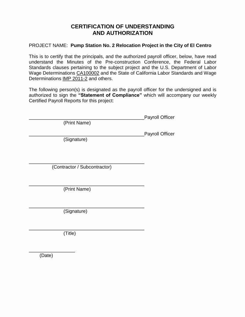
CERTIFICATION OF UNDERSTANDING AND AUTHORIZATION
PROJECT NAME: Pump Station No. 2 Relocation Project in the City of El Centro This is to certify that the principals, and the authorized payroll officer, below, have read understand the Minutes of the Pre-construction Conference, the Federal Labor Standards clauses pertaining to the subject project and the U.S. Department of Labor Wage Determinations CA100002 and the State of California Labor Standards and Wage Determinations IMP 2011-2 and others. The following person(s) is designated as the payroll officer for the undersigned and is authorized to sign the “Statement of Compliance” which will accompany our weekly Certified Payroll Reports for this project: Payroll Officer (Print Name) Payroll Officer (Signature) (Contractor / Subcontractor) (Print Name) (Signature) (Title) (Date)

FEDERAL
PREVAILING WAGE
RATES

STATE
PREVAILING WAGE
RATES