Embed Size (px)
Citation preview

TECHNICAL
SPECIFICATIONS
69/12.47 KV POWER
TRANSFORMER FOR
CITY AND BOROUGH OF
SITKA
MARINE STREET
SUBSTATION
June 1, 2018

Contents
1 GENERAL 1
2 SEISMIC FORCES 1
3 STANDARDS 2
4 TRANSFORMER RATINGS 3
5 AUDIBLE SOUND LEVEL 4
6 TANK 4
7 GROUNDING 4
8 FACILITIES FOR LIFTING, MOVING, JACKING, AND ANCHORING 5
9 CORE 5
10 WINDINGS 5
11 BUSHINGS 6
12 CURRENT TRANSFO RM ERS 6
13 DE-ENERGIZED TAP CHANGER 7
14 ENERGIZED LOAD TAP CHANGER (LTC) 7
15 SURGE ARRESTERS 9
16 INSULATION & COOLING SYSTEM 9
17 CONTROL CABINET 11
18 ACCESSORIES 13
19 NAMEPLATES 16
20 COLOR 16
21 CLEANING AND PAINTING 17
22 TESTING AND INSPECTION 18
23 SUBMITTALS 20
24 PACKING FOR SHIPMENT 22
25 TECHNICAL EVALUATION SHEET 23

69/12.47 kV Power Transformer
June 1, 2018 Page 1 Technical Specifications
Marine Street Substation
1 GENERAL
A. The owner, City and Borough of Sitka shall be referred to as “Sitka” for the remainder of this document.
B. This specification defines a 69/12.47 kV, 3-phase, outdoor, 15/20/25 MVA, power transformer (Transformer).
C. Suppliers shall specify in their response to the RFB in writing whether exceptions are taken to any of the Bid Documents.
D. Suppliers shall include a general description of the construction, including drawings, photographs, or catalog cuts which show the general construction, and any accessories included.
E. The Transformer will be installed on a 69 kV , 3-phase, solidly-grounded wye 60 Hz, transmission system on the high side and will serve as substation transformer for a delivery voltage of 12.47 kV , wye, solidly grounded distribution system. The elevation above sea level is 3000 f t or less. The ambient temperature range is −40ºC to +40ºC.
F. The Transformer will be protected on the high-side with gas circuit breakers and on the low-side with vacuum circuit breakers.
G. The Transformer may be operated in parallel on the secondary side with an existing transformer bank for brief (up to 1 hour) periods of time during switching operations. The existing transformers are three single phase units, connected delta-wye, each rated at 6,667 kVA and 6.55, 6.54 and 6.61% impedance.
H. The Transformer will be installed in a marine environment. Atmosphere is considered to be highly corrosive due to high quantities of ocean salt spray. Contractors shall specify in writing the specific features to be provided to ensure the transformer is suitable for a marine environment.
I. All drawings will be additionally supplied to the owner in Autocad format.
2 SEISMIC FORCES
A. The seismic forces to which this equipment may be subjected are outlined in the International Building Code and IEEE 693 as shown in Table I.
Table I: Seismic Loading Design Category D 0.2 second MCE Spectral Response Acceleration, (SS) 1.5 1.0 second MCE Spectral Response Acceleration, (S1) 0.55 Site Class D Site Use Group III Seismic Importance Factor, Ie 1.50 IEEE 693-2005 Seismic Qualification Level High

69/12.47 kV Power Transformer
June 1, 2018 Page 2 Technical Specifications
Marine Street Substation
3 STANDARDS
1. In the event a conflict occurs between these codes and the technical specifications, the requirements of the different parts shall govern to the extent of such conflict in the following sequence: mandatory governmental regulations the Specification Data Sheets and drawings provided by the Buyer; this specification; and the referenced industry codes and standards.
A. The equipment shall meet the performance requirements of and be designed, manufactured, and tested in
accordance with the latest applicable standards of:
Overall Standards:
1. American National Standards Institute (ANSI)
2. American Society for Testing and Materials (ASTM)
3. American Welding Society (AWS)
4. Institute of Electrical and Electronics Engineers (IEEE)
5. International Building Code (IBC)
6. National Electrical Code (NEC)
7. National Electrical Manufacturers Association (NEMA)
8. National Electrical Safety Code (NESC)
9. Occupational Safety and Health Administration (OSHA)
10. Underwriters Laboratories (UL)
Specific Standards: 1. C57.12.00 General Requirements for Liquid Immersed Distribution, Power and Regulating Transformers 2. C57.12.70 Terminal Markings and Connections for Distribution and Power Transformers 3. C57.12.90 Test Code for Liquid-Immersed Distribution, Power, and Regulating Transformers and Guide
for Short-Circuit Testing of Distribution and Power Transformers 4. C57.13 Requirements for Instrument Transformers 5. C57.19.00 General Requirements and Test Procedure for Outdoor Power apparatus Bushings. 6. C57.106 Guide for Acceptance and Maintenance of Insulating Oil in Equipment. 7. C57.93 IEEE Guide for Installation of Liquid Immersed Power Transformers 8. C57.115 Guide For Loading Mineral-Oil-Immersed Power Transformers, Rated in Excess of 100 MVA
(65oC Winding Rise) 9. C57.116 Guide for Transformers Directly Connected to Generators 10. C62.11 Standard for Metal-Oxide Surge Arresters for AC Power Circuits 11. National Electrical Manufacturers Association (NEMA) 12. LA 1 Surge Arresters 13. TR 1 Transformers, Regulators and Reactors 14. 107 Methods of Measurement of Radio Influence Voltage of High-voltage Apparatus 15. American Society for Testing and Materials (ASTM) 16. D117 Guide to test Methods and Specifications for Electrical Insulating Oils of Petroleum Origin 17. D3487 Specification for Mineral Insulating Oil Used in Electrical Apparatus 18. See Specification 01800 for additional codes, standards and regulations.

69/12.47 kV Power Transformer
June 1, 2018 Page 3 Technical Specifications
Marine Street Substation
4 TRANSFORMER RATINGS
A. All Transformer ratings shall be in accordance with IEEE standards in the C57.12 series as applicable to liquid- immersed power transformers. Specific Transformer ratings shall meet the characteristics shown in Table II.
Table II: Transformer Characteristics
Characteristic Value Type Substation Outdoor Power Transformer Transformer Class I Winding Configuration Delta - Grounded Wye Operation 3-phase High Voltage Bushing Type/Location Porcelain/Top Mount Medium Voltage Bushing Type/Location Porcelain/Side (Throat) Mount with cable
supports Parallel Operation Required Yes Ambient Temperature Range −40ºC to +40ºC Installed Elevation Less than 3, 000 f t Nominal Frequency 60 Hz – See this Table for details Maximum Primary System Voltage 72.5 kV Nominal High Voltage Primary 69 kV Grounded Wye Nominal Medium Voltage Secondary 12.47 kV Grounded Wye Phase Relationship High voltage shall lead the medium
voltage by 30 degrees Impedance IEEE Standard Cooling Class ONAN/ONAF/ONAF Coolant Mineral Oil Temperature Rise by Hottest Spot 65ºC/80ºC Continuous Load Rating at 65ºCRise 15/20/25MVA ONAN/ONAF/ONAF High Voltage BIL 350 kV Medium Voltage BIL 110 kV Surge Arresters
Type Station Class, Metal Oxide Type High Voltage MCOV 42 kV Medium Voltage MCOV 8.4 kV
DC Alarm/Trip/Control Power Voltage 125VDC AC Auxiliary Power Voltage 120/240VAC, 1φ , 60 Hz De-Energized Full Capacity High Voltage Taps 2.5 % Taps Energized Full Capacity Medium Voltage Tap Changer 0.625 % Taps High Voltage Current Transformers See Section 12 Medium Voltage Current Transformers See Section 12 Probable Operating Frequency Range 59.9 to 60.1 Hz

69/12.47 kV Power Transformer
June 1, 2018 Page 4 Technical Specifications
Marine Street Substation
5 AUDIBLE SOUND LEVEL
A. Audible sound level shall not exceed 70 decibels maximum on the A-weighted scale. This value shall not be exceeded with rated voltage per turn applied to the windings and the transformer in the tap position which produces the highest audible sound level, and all auxiliaries energized.
6 TANK
A. The Transformer tank shall be manufactured from steel plates with welded seams.
B. It shall conform to the requirements of IEEE C57.12.10.
C. It shall conform to the requirements of IEEE C57.12.10.5.8 including withstanding pressures at least 25% greater than the maximum operating pressure
D. The Transformer shall be fabricated for loading in accordance with ANSI/IEEE C57.91
E. Hand holes and manholes shall be located so that access does not require removal of equipment or accessories.
Manholes shall be a minimum of 20 inches in diameter. Side mounted handholes shall be provided above the core to allow external access to bottom connected bushings.
F. A mounting plate for a fall protection mast shall be welded to the top of the Transformer tank capable of accepting a Wisconsin Lifting Specialty, Inc. Model P-C tether pole
G. Transformer tank top shall be domed to prevent water accumulation, and have a skid-resistant surface.
H. Unless alternate method is used to prevent corrosion of exterior bottom of Transformer tank, Transformer tank
design shall be such that ventilation is provided between concrete supporting slab and bottom of Transformer tank.
7 GROUNDING
A. Grounding pads shall consist of four NEMA two-hole copper-faced steel pads, which are drilled, tapped, and attached to the tank per IEEE C57.12.10, one on each side of main tank wall.
B. In addition:
1. Studs and clips shall be provided to secure the ground conductor from the high and low voltage surge arrestors down to the ground pads.
2. A complete isolated ground bus system for each Transformer neutral shall be provided. A copper bus bar of appropriate size shall be routed from neutral bushing(s) down the tank to a point six inches (6”) above the Transformer base. The end of the bus bar near the Transformer base shall include holes to accommodate a NEMA two-hole paddle connection. The ground bus system shall be completely assembled and finished with the same paint system as the Transformer with the exception of the portion of the bus that is designed to accommodate the two-hole connection. This portion shall be left unfinished.

69/12.47 kV Power Transformer
June 1, 2018 Page 5 Technical Specifications
Marine Street Substation
8 FACILITIES FOR LIFTING, MOVING, JACKING, AND ANCHORING
A. Facilities for lifting, moving, jacking and anchoring the complete Transformer (with oil), as well as for separately lifting the cover, and for lifting the core and coil assembly from the tank, shall be provided in compliance with IEEE C57.12.10.
B. Minimum dimensions and clearances for jacking provisions shall be specified in the Contractor’s drawings. Bottoms of jacking pads shall be minimum of 15” above Transformer base. Corners of lifting eyes and lugs shall be beveled.
C. The Transformer base shall be designed for installation on a concrete slab foundation. The Contractor shall indicate on his outline drawing the dimensions of the Transformer base, the center of gravity, and the attachment points from the Transformer to the foundation in order that Sitka may confirm the Transformer/foundation fit. The Transformer base shall be designed to allow for anchorage by spot welding the Transformer base to steel members embedded within the concrete slab. The location, type, size, and length of the welds shall be designated by the manufacturer.
D. Provisions shall be made for lifting the core and coil assembly from the tank per ANSI C57.12.10
9 CORE
A. The core shall be constructed of the highest quality, non-aging, cold-rolled, grain-oriented, stress-free, thin- silicon-steel laminations having permeability and low hysteresis losses. The steel shall be properly annealed and have smooth surfaces at the edges. Each sheet shall have an insulated surface, which is impervious to hot Transformer oil. The core shall be rigidly clamped and blocked to prevent deteriorating vibrations, interference with oil circulation, short circuits, objectionable noise levels, and shipment distortions. Any internal blocking or bracing used, which is to be removed from the Transformer at its destination, shall be painted a bright color, such as red or yellow. The core shall be securely grounded to the tank. The core ground connection shall be external of the tank and located on top of the tank with the provisions to temporarily isolate the core ground from the main tank for testing purposes. A means shall be provided for properly handling the core assembly when it is un-tanked.
10 WINDINGS
A. All Transformer windings shall be designed and wound with maximum short circuit strength as a primary design criterion. All windings shall be furnished with insulation that will permit continuous operation at a winding rise of 65ºC above ambient and a hot spot rise of 80ºC without affecting normal life expectancy of insulation. Winding leads shall be readily accessible from a manhole in the tank cover.
B. Copper shall be used as the winding material. No alternatives will be permitted.
C. All high voltage winding leads shall be brought out through bushings utilizing draw lead style connections.

69/12.47 kV Power Transformer
June 1, 2018 Page 6 Technical Specifications
Marine Street Substation
11 BUSHINGS
A. All bushings shall be removable without removing the tank cover. Primary and secondary bushings shall be
constructed and mounted in accordance with IEEE C57.12.10. Oil-filled bushings shall be equipped with oil level indication. All bushings shall be so designed that there will be no undue stressing of any parts due to temperature changes.
B. Porcelain used in the bushings shall be manufactured by the wet process and shall be homogeneous, free from laminations, cavities, or other flaws affecting its mechanical strength or dielectric quality. The glazing of the porcelain shall be free from imperfections, such as blisters or burns.
C. Bushings shall be rated for operation at the altitude specified.
D. For internal bottom connected bushings, slotted connection paddles shall be provided between the bottom bushing connections and the Transformer phase leads with easily accessible permanently fixed studs facing outward.
E. All bushings shall meet the requirements of IEEE C57.19.00 and C57.19.01. All bushings shall safely withstand specified Transformer test levels.
F. Bushings shall be ANSI 70 light gray in color.
G. Bushing caps shall be fire engine red in color.
H. Bushing terminals shall include bronze NEMA 4-hole paddle connector suitable for customer connections.
I. All bushings shall have power factor test taps, with factory test values clearly stamped on nameplates located on each bushing.
J. Medium voltage bushings shall be mounted with their test taps pointing towards the ground.
K. Only ABB or PCORE manufactured bushings will be accepted.
L. Bushings above 150 kV BIL shall be condenser type, with capacitance graded layers of insulating material and
equipped with a capacitance or power factor test tap.
M. Porcelain parts rated below 450 kV BIL shall be one-piece.
12 CURRENT TRANSFORMERS
A. The Transformer shall have 14 multi-ratio, bushing-type current transformers. Bushing Current Transformers (BCT) shall conform to the following requirements:
1. BCT’s shall conform to IEEE C.57.13.
2. BCT’s shall be provided in conformance with IEEE C57.12.10.
3. Minimum continuous thermal current Rating Factor (RF) of 2.0.
B. BCT’s shall be provided as follows:

69/12.47 kV Power Transformer
June 1, 2018 Page 7 Technical Specifications
Marine Street Substation
1. Medium Voltage Bushings
i. X 0 . . . . . . . . . . . . . . . . . . . . . . . . . . . . . . . . . . . . . . . . . . . . . . . . . . . . . . . . . . . 2000 : 5 MRCT, C400, RF = 2.0 ii. X 1, X 2, X 3 . . . . . . . . . . . . . . . . . . . . . . . . . . . . . . . . . . . . . . . . . . . . . . . . . . . 2000 : 5 MRCT, C400, RF = 2.0 iii. X 1, X 2, X 3 . . . . . . . . . . . . . . . . . . . . . . . . . . . . . . . . . . . . . . . . . . . . . . . . . . 2000 : 5 MRCT, C400, RF = 2.0
2. High Voltage Bushings
i. H0 . . . . . . . . . . . . . . . . . . . . . . . . . . . . . . . . . . . . . . . . . . . . . . . . . . . . . . . . . . . . 300 : 5 MRCT, C400, RF = 2.0 ii. H1, H2, H3 . . . . . . . . . . . . . . . . . . . . . . . . . . . . . . . . . . . . . . . . . ……... . . . . . 300 : 5 MRCT, C400, RF = 2.0 iii. H1, H2, H3 . . . . . . . . . . . . . . . . . . . . . . . . . . . . . . . . . . . . . . . . . . . . . . . . . . . 300 : 5 MRCT, C400, RF = 2.0
13 DE-ENERGIZED TAP CHANGER
A. Five full capacity taps shall be supplied on the high voltage winding. Two taps shall be provided above and two taps below the nominal voltage. Each tap shall represent a voltage change of 2.5 % as represented by the following table.
Tap Position Value
1 72450V 2 70725V 3 69000V 4 67275V 5 65550V
B. The tap voltages and maximum line currents shall be shown on the nameplate in volts and amps. The taps shall be designated both on the nameplate and the tap changer indicating plate by numbers in sequence with the numeral ”1” being assigned to the voltage rating, which provided the greatest ratio transformation.
C. The tap changer shall be capable of operating only while the Transformer is de-energized. It shall be hand- wheel operated with a position indicator and shall be located on the Transformer tank at a level so that it may be operated from ground level. The hand-wheel shall be located no less than 3 f t from the Transformer base level and no more than 5 f t from the Transformer base level. Facilities for locking in any tap position shall be provided.
D. The tap changer shall be capable of withstanding fully rated Transformer short-circuit currents.
E. A provision shall be provided to prevent moisture accumulation in the tap changer gears and/or hand operator mechanism.
14 ENERGIZED LOAD TAP CHANGER (LTC)
A. LTC shall meet all requirements of IEEE C57.131.
B. Full rated MVA shall be available at all tap positions. There shall be a total of 33tap positions to provide the following voltage ranges:

69/12.47 kV Power Transformer
June 1, 2018 Page 8 Technical Specifications
Marine Street Substation
Above normal voltage 10% with 16 positions Below normal voltage 10% with 16 positions
C. The LTC shall be designed to operate under the following conditions:
1. Automatic operation, controlled by voltage sensing relays located on the medium voltage side, provided with adjusting devices for selecting the operating range and timing relays adjustable from 15 to 60 seconds for delaying the tap changing operation in both directions. This operation shall be performed simultaneously on all three phases.
2. Manual operation by means of electrical controls, operating on all three phases simultaneously, initiated from either the transformer control cabinet or from a remote control panel.
3. Manual operation by mechanical means located at the unit, for individual operation of the tap changer. When the mechanical manual device is engaged, operation by electrical means shall be positively blocked.
4. The tap changer operating devices shall include the following:
i. Line drop compensation circuit including current transformer.
ii. Main circuit breaker with thermomagnetic protection for the supply power circuit.
iii. Tap position indicator.
iv. Operation counter with totalizer.
v. Electric motor or solenoid.
vi. Speed reducer switches.
vii. Motor starter, if applicable, with thermal overload protection.
viii. Selsyn equipment, or TLMS signal, including auxiliary devices for remote indication of tap position. ix. Rheostat for remote tap position indication.
x. Brakes, limit switches, etc. if required.
xi. Means for manual operation of the tap changer.
xii. Terminal blocks for outgoing conductors.
xiii. All auxiliary devices required for satisfactory operation.
xiv. External motor power terminals
xv. Provision for future paralleling with a second transformer tap changer.
5. Current transformers for the compensation circuit shall conform to IEEE C.57.13.
6. The tap changer switch contacts shall be mounted in a separate tank, filled with insulating liquid which will not mix with the insulating liquid in the main tank. The tap changer tank shall be provided with means for allowing gases produced in its interior to escape through a free breathing desiccant breather. The breather shall be a Comem SDB or a Messko MTraB® maintenance free dehydrating breather or approved equal.
7. Other accessories, such as transfer switches, resistors, current limiters, instrument transformers, and com- mutating resistances between taps shall also be mounted outside of the main tank.
8. The tap changer tank shall be filled with the same type of insulating oil as is used in the main tank. Provide liquid level indicators, liquid temperature indicators, drain valves and fill valves for each compartment of the LTC tank. The tap changer tank shall be formed in a manner that will provide a low point in the tap changer tank. A drain valve shall be installed at the low point to allow complete draining of the insulating oil from the tap changer tank. Access to the tap changer compartments shall be possible without opening the main tank.

69/12.47 kV Power Transformer
June 1, 2018 Page 9 Technical Specifications
Marine Street Substation
9. The tap position indicators shall be legible from outside and so located as to allow reading while operating the tap changer manually at grade.
10. The tap changer shall be designed in accordance with ANSI/IEEE standards. It shall be capable of with- standing mechanical forces produced by short-circuits as specified, and it shall be possible to complete the tap changing operation under these short-circuit conditions.
11. The electric control system shall change taps in all three phases simultaneously. In case one of the taps gets out of step, the control system shall be blocked and an alarm signal shall be initiated.
12. The tap changer shall be able to perform not less than 500, 000 operations without replacement parts. 13. Operations Counter shall be supplied
14. The following devices shall be furnished and installed by the Contractor:
i. Beckwith, M-2001D 16-bit digital tapchanger control with DNP 3.0 communications protocol including communication software (TapTalk®) compatible with Windows® 7 operating system.
ii. A complete set of devices for remote indication of tap position, including Selsyn motors or equivalent devices, tap position indicator, etc.
D. The tap changer shall be a reactive-bridging type utilizing vacuum switching technology, Reinhausen Vacutap® RMV-II or ABB VRLTC™.
15 SURGE ARRESTERS
A. Station class Metal-Oxide type surge arresters shall be provided at the ratings specified B. Station class surge arresters shall be mounted on the primary and secondary sides of Transformer. The surge
arresters shall be in compliance with IEEE C62.22.
C. Surge arresters will be mounted with a test equipment accessible ground plane on the primary and secondary sides of the Transformer.
D. The Contractor shall provide mounting brackets, mounting hardware and all connections required for complete assembly and mounting of the Contractor supplied arrester discharge counters for each arrester supplied with the Transformer. The discharge counter will have a continuous millimeter current reading indicating the grading current of the arrester.
16 INSULATION & COOLING SYSTEM
A. Oil
1. Oil shall be pure, type II, inhibited, mineral oil obtained by the fractional distillation of petroleum. Oil shall be prepared and refined especially for use in transformers, having a minimum flash point of 160ºC. It shall be free from moisture, acid, alkali, and injurious sulfur compounds. The oil shall not form a deposit under normal operating temperatures. The minimum allowable dielectric strength of the oil shall be 26 kV when measured in accordance with American National Standards Methods of Testing Electrical Insulating Oils, C59.2.
2. The Contractor shall furnish test results certifying the oil supplied with this Equipment, and any oil used in production or testing of this Equipment, is classified as “PCB-Free” (polychlorinated biphenyl) with contamination of less than 1 PPM (parts per million). The Transformer nameplate shall clearly mark the Transformer as “PCB-Free”. Sitka will not accept delivery of the unit until such results are received. The

69/12.47 kV Power Transformer
June 1, 2018 Page 10 Technical Specifications
Marine Street Substation
Contractor is also responsible for providing the same certification as listed above for any oil supplied in drums for makeup oil.
B. Oil Preservation System
1. The Transformer shall utilize a dry nitrogen blanket type system, capable of housing a single size 200
nitrogen bottle. A bleed tube for gas blanket dew point measurement shall be provided. Suitable valves shall be provided to permit purging the gas space and testing the seal on the tank by admitting dry nitrogen under pressure.
2. The Transformer dry nitrogen blanket system shall include a 3 stages of regulating, second stage bypass valve, sump bleed valve, pressure relief valve(+6.5PSI), pressure meter and three alarm contacts. The alarm contacts shall indicate Transformer tank inert gas high and low pressure and inert gas cylinder low pressure. All piping shall be flexible copper, or a stainless steel braided sleeved hose where flexibility is needed(ie. Cylinder connection).
3. Nitrogen cylinder connection shall be a minimum of 24” long, terminated with a CGA580 connection on the cylinder side.
4. Transformer shall be shipped with a bottle that doesn’t need to be returned to the supplier upon receipt of the transformer
5. A viewing window on the door allowing gauges to be read without opening the door is required. 6. Cabinet shall be 316 stainless, with a stainless steel bottom and stainless steel latches.
C. Filling/Draining/Processing Valves
1. A combination drain and lower filter valve shall be provided. This valve shall provide for drainage of oil to within 1 inch of the tank bottom and for outlet of the oil to a filtering means. The size of the drain valve shall be 2” and have 2” NPT threads with a pipe plug in the open end. The drain valve shall have a built-in 3/8 inch sampling device which shall be located in the side of the valve between the main valve seat and the pipe plug. This sampling device shall have a 5/16”-32 male thread and be equipped with a cap. The valve material shall be brass.
2. An upper filter valve of the globe type shall be located below the 25ºC liquid level and shall be suitable for the return of filtered oil. The size of the upper filter shall be 2” and have 2” NPT threads with a pipe plug in the open end. The valve material shall be brass.
3. There shall be a top filling valve with a minimum size of 2”.
D. Forced Cooling System
1. Transformers shall be designed for continuous self-cooled and two additional stages of force cooled operation. Winding temperature rise by resistance shall not exceed 55ºC and hottest spot winding temperature rise shall not exceed 65ºC.
2. A thermally upgraded insulation system shall be provided allowing continuous loading at 112% of the 55ºC MVA rating with winding temperature rise not exceeding 65ºC and hottest spot temperature not exceeding 80ºC.
3. The forced cooling equipment (fans) shall be suitable for connection to a 120/240V, single phase, 60 Hz power supply. The cooling-equipment shall be individually connected to the power supply in a protective and weatherproof manner. The motors shall be total enclosed without centrifugal clutch, permanently lubricated, and protected by circuit breakers. Fans shall be mounted in such a manner that will facilitate maintenance and/or replacement. Fan blades shall be fiberglass. The control for adjusting the temperature at which the cooling equipment starts shall be readily accessible. All fans shall be guarded in accordance
69/12.47 kV Power Transformer
June 1, 2018 Page 11 Technical Specifications
Marine Street Substation
with OSHA 1910.212.
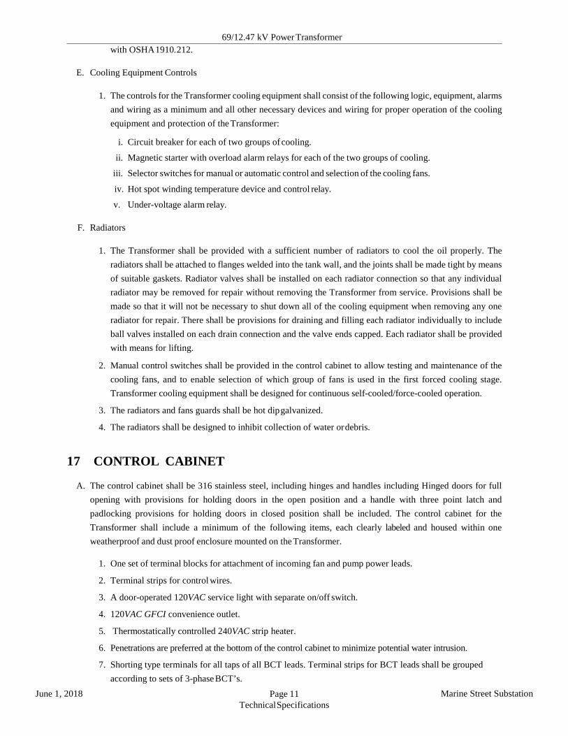
E. Cooling Equipment Controls
1. The controls for the Transformer cooling equipment shall consist of the following logic, equipment, alarms and wiring as a minimum and all other necessary devices and wiring for proper operation of the cooling equipment and protection of the Transformer:
i. Circuit breaker for each of two groups of cooling.
ii. Magnetic starter with overload alarm relays for each of the two groups of cooling.
iii. Selector switches for manual or automatic control and selection of the cooling fans.
iv. Hot spot winding temperature device and control relay.
v. Under-voltage alarm relay.
F. Radiators
1. The Transformer shall be provided with a sufficient number of radiators to cool the oil properly. The radiators shall be attached to flanges welded into the tank wall, and the joints shall be made tight by means of suitable gaskets. Radiator valves shall be installed on each radiator connection so that any individual radiator may be removed for repair without removing the Transformer from service. Provisions shall be made so that it will not be necessary to shut down all of the cooling equipment when removing any one radiator for repair. There shall be provisions for draining and filling each radiator individually to include ball valves installed on each drain connection and the valve ends capped. Each radiator shall be provided with means for lifting.
2. Manual control switches shall be provided in the control cabinet to allow testing and maintenance of the cooling fans, and to enable selection of which group of fans is used in the first forced cooling stage. Transformer cooling equipment shall be designed for continuous self-cooled/force-cooled operation.
3. The radiators and fans guards shall be hot dip galvanized.
4. The radiators shall be designed to inhibit collection of water or debris. 17 CONTROL CABINET
A. The control cabinet shall be 316 stainless steel, including hinges and handles including Hinged doors for full
opening with provisions for holding doors in the open position and a handle with three point latch and padlocking provisions for holding doors in closed position shall be included. The control cabinet for the Transformer shall include a minimum of the following items, each clearly labeled and housed within one weatherproof and dust proof enclosure mounted on the Transformer.
1. One set of terminal blocks for attachment of incoming fan and pump power leads.
2. Terminal strips for control wires.
3. A door-operated 120VAC service light with separate on/off switch.
4. 120VAC GFCI convenience outlet.
5. Thermostatically controlled 240VAC strip heater.
6. Penetrations are preferred at the bottom of the control cabinet to minimize potential water intrusion.
7. Shorting type terminals for all taps of all BCT leads. Terminal strips for BCT leads shall be grouped according to sets of 3-phase BCT’s.

69/12.47 kV Power Transformer
June 1, 2018 Page 12 Technical Specifications
Marine Street Substation
8. Bolted, removable 316 stainless conduit plate, 16 gauge maximum, in bottom of cabinet, which can be removed for conduit entry punching in the field.
9. All items of the cooling system as listed hereinafter which are not mounted on external devices or on/in the Transformer tank.
10. Equipment terminal blocks with washer head binding screws, covers, and white terminal identification marking strips General Electric type EB-25, Marathon type 1600, or equal. Screw shall accept standard holding type screw drivers only. Shorting style of terminal blocks shall come with shorting screws, one for each polarity and non-polarity CT connection per CT.
11. Minimum No. 12 AWG for control and minimum No. 10 AWG for current transformer wiring. Provide insulated ring-tongue terminals on each end of control wiring.
12. Fan motor starters, control power transformers, and protective devices as required for a complete and operational Transformer shall be furnished as part of control cabinet.
13. Provide undervoltage relays to actuate an alarm on loss of any external auxiliary AC or 125VDC power source with contacts wired to terminal blocks for external use.
14. Provide SEL-2505 Remote Input/Output Module, rated for use with 125 VDC control and power. Wire all transformer device alarm and trip contacts from terminal blocks to SEL-2505. Communications shall be by multimode fiber. SEL Part# 2505324XX
15. Locate cabinet at height above bottom of base support such that it is suitable for operation and inspection by person standing at level of bottom of base support. Top of cabinet height shall be no more than 6’-7” (2m) measured from bottom of base support elevation.
16. Provide operating and maintenance manual holding slot integral to control cabinet with hinged cover.
17. Wiring
i. Wiring, thermocouple wiring, and connections shall be separately supported and protected to prevent damage during shipment or after final installation.
ii. Wiring shall be neatly bundled, terminated, and marked in accordance with connection diagrams.
18. Identification and Tagging
i. Provide permanent nameplates to identify protective relays, meters, instruments, selector switches, indicating lights, terminal blocks, and other devices within various compartments.
ii. Nameplates shall have black lettering on white background. Fasten in place using type 316 stainless steel, self-tapping screws.
iii. Nameplates shall be heat and UV-resistant. iv. Terminal blocks shall be clearly marked for wiring using permanent printed markers. v. Each internal interconnecting wire shall be identified at both ends with sleeve type wire markers with
from/to information. vi. Tag equipment with item number as shown on O&M manual datasheets.
B. All electrical devices, including fans, pumps, control relays, alarm contacts, current transformer secondaries,
etc., which mount on/in the Transformer shall be factory wired complete from the devices to terminals, so that only the field connections necessary for operation shall be the main power supply conductors for the fans, pumps, and auxiliary equipment, and the attachment of incoming control conductors and field BCT leads to the terminals. There shall be adequate room inside the control cabinet for connection of all interconnection wiring without crowding, and all equipment located therein shall be uncrowded and easily accessible for safe inspection, removal, and repair. Top of the cabinet shall be no more than six feet, seven inches above the Transformer

69/12.47 kV Power Transformer
June 1, 2018 Page 13 Technical Specifications
Marine Street Substation
bottom elevation. All factory wiring shall be type SIS/XHHW-2.
C. In addition to those items listed above, the Transformer shall have the following equipment in the control cabinet:
1. One three-position tap control switch, Raise-Off-Lower, provided with momentary contacts and spring return to “Off” position for automatic operation.
2. One manual tap selector with 33 positions.
3. One selector switch with Local-Off-Remote (43T1).
4. One selector switch with Parallel-Independent (43P).
5. One selector switch with Automatic-Manual (43S).
6. Line drop compensator circuit.
7. Out-of-step tap change lockout and alarm circuitry.
8. Terminals for connecting voltmeter to read the controlled voltage.
9. Time relays as required.
10. Main circuit breaker with thermomagnetic protection for the control power circuit.
11. Indicator of tap position.
12. Indicator of voltage at reference bus.
13. Internal lights and heater with respective switches.
14. “Off” tap position signal for remote indication and alarm.
15. “Local” and “Remote” tap position indicator transmitter.
16. All auxiliary devices and accessories required for satisfactory operation.
18 ACCESSORIES
A. Liquid Level Indicator
1. The Transformer shall be equipped with magnetic liquid-level indicators, one for the main tank, and the other for the LTC, which shall be readable when standing at base level. Liquid level shall be annunciated by two stages (low, low-low) of oil level.
2. The liquid level indicator shall drive two contacts each for two separate liquid levels. The first level being an alarm level and the second level being a tripping level.
3. The liquid level indicator alarm contact shall be nonadjustable and shall be set close at the minimum safe operating level of the liquid.
B. Liquid Temperature Indicator
1. Dial-type thermometers shall be mounted on the side of the tank, one for the main tank and the other for
the LTC. The thermometer shall have a dark- faced dial with light markings, a light-colored indicating hand and an orange-red maximum indicating hand with provisions for resetting. The dial markings shall cover a range of 0ºC to 120ºC. The words “liquid temperature” shall be on the dial.
2. The thermometer shall be direct-stem mounted in a closed well at a suitable level to indicate the top liquid temperature.
3. Alarm contacts shall be provided for temperatures of 70ºC, 80ºC and 90ºC.
4. Trip contacts shall be provided for temperatures of 100ºC.
C. High Voltage Winding Temperature Indicator

69/12.47 kV Power Transformer
June 1, 2018 Page 14 Technical Specifications
Marine Street Substation
1. A dial-type thermometer shall be mounted on the side of the tank. The thermometer shall have a dark-
faced dial with light markings, a light-colored indicating hand and an orange-red maximum indicating hand with provisions for resetting. The dial markings shall cover a range of 0ºC to 120ºC. The words “winding temperature” shall be on the dial.
2. The thermometer shall be direct-stem mounted in a closed well at a suitable level to indicate the top HV winding temperature.
3. Alarm contacts shall be provided for temperatures of 70ºC, 75ºC and 90ºC.
4. Trip contacts shall be provided for temperatures of 120ºC.
5. Supplier set both stages fans to come on at their recommended winding temperature setpoints.
D. Alarm and Trip Contacts
1. Non-grounded alarm and trip contacts for liquid level and temperature indicators shall be furnished. Alarm contacts shall be suitable for interrupting:
i. 0.05 A direct current inductive load.
ii. 0.5 A direct current non-inductive load.
iii. 250V maximum in all cases.
E. A fault pressure relay on the LTC and main tank and reset switch shall be furnished for the Transformer. Voltage shall be 125VDC. An auxiliary relay and reset switch shall be located in the Transformer cabinet. The auxiliary relay shall be provided with a minimum of three S.P.S.T. N.O. contacts. The seal-in relay shall be a Qualitrol 909 Seal-In Relay, with no substitutions accepted.
F. Pressure/Vacuum Gauge
1. A pressure/vacuum gauge shall be furnished. The gauge shall have a dark-faced dial with light markings and a light-colored pointer. The scale range for the pressure gauge shall be between 10 psi positive and 10 psi negative.
2. Alarm contacts shall be provided for low tank pressure, high tank pressure, low cylinder pressure and high cylinder pressure.
G. Pressure Relief Device
1. The pressure relief device shall be the mechanical type, which will automatically re-seal after excess
pressure has been vented. 2. Provide one pressure relief device for the main tank and the other for the LTC.

69/12.47 kV Power Transformer
June 1, 2018 Page 15 Technical Specifications
Marine Street Substation
3. Alarm contacts shall be provided.
H. A PVC/HDPE tube assembly shall be installed such that in the case of an overpressure event, the oil is deverted down the side of the transformer towards the ground and not into the air End of pipe shall be within 3 feet from the base of the transformer.
I. The supplier shall provide any special tools, which are necessary for maintenance or installation of the
Transformer.
J. All gaskets used in construction of the Transformer shall be of reusable rubber with means provided for con- trolled compression. The supplier shall furnish a spare set of gaskets for the Transformer. In addition to a complete set of spare gaskets, a new set for the use during radiator installation shall be provided
K. NEMA 4-hole pad tinned bronze stud connectors shall be furnished on all bushings with the same current carrying rating as the bushings and the Transformer winding.
L. Cabinet Heaters
1. The Contractor shall provide suitable strip heaters in the control cabinets. Heaters shall be sufficient to allow for operation at −40ºC to +40ºC.
2. Heaters shall be capable of maintaining cabinet internal temperature above dew point.
3. Heaters shall be spaced away, and be thermally insulated from devices and painted surfaces.
4. Heater shall be controlled by an adjustable thermostat.
M. Spare Parts
1. The Contractor shall provide Sitka with a list of recommended spare parts for the Transformer and their costs.
N. Tether Pole Mounting Plate
1. Provide mounting plate on top of Transformer for Wisconsin Lifting Specialty, Inc. Model P-C tether pole.
O. Additional alarm contacts shall be provided as required to indicate failure of devices critical to Transformer
operation. Contacts shall close when alarm is to be transmitted.
P. The Transformer shall be outfitted with a complete factory installed DRMCC-E3 monitoring, control, and communication device manufactured by Dynamic Ratings. This device shall be configured with the E3-8150 option which includes but is not limited to the following:
1. Cooling control.
2. Local display.
3. Thermal monitoring:
i. Top oil temperature.
ii. Ambient temperature.
iii. Main tank oil temperature (Delta T Monitoring).
iv. Calculated winding hot spot temperature.

69/12.47 kV Power Transformer
June 1, 2018 Page 16 Technical Specifications
Marine Street Substation
v. Calculated top oil temperature. vi. Calculated insulation loss of life.
4. Single phase voltage and current load monitoring - H1 phase.
5. Fan contactor and fan current monitoring including fan sequencing and exercising.
6. OLTC/LTC monitoring:
i. Tap position.
ii. Temperature (Delta T Monitoring).
iii. Motor energy monitoring.
iv. Summary of historical operation counter.
v. Contact wear.
vi. Reversing switch exercise.
vii. Auto-cleaning of reversing switch system.
7. Analog oil levels and analog pressures (main tank, nitrogen cylinder pressure).
8. Modbus communication: Ethernet over fiber (multimode fiber, core size 62.5/125 µm).
9. Sudden pressure and pressure relief contact monitoring.
10. Core ground current monitoring. 19 NAMEPLATES
A. A durable stainless steel nameplate shall be affixed to the Transformer by the supplier. The text shall be black.
It shall bear the information listed on example Nameplate C, Table 7, IEEE C57.12.00. The following information shall also be included:
1. Current transformer locations and ratings.
2. Maximum positive and negative operating pressures of the oil preservation system.
3. Pounds of vacuum filling pressure for which tank is designed.
4. Oil level in inches below the top surface of the highest point of the manhole flange at 25ºC. Oil level change in inches per 10ºC change in oil temperature.
5. Sound pressure level test data: dB(A) and dB(C)
6. Any other information, which the supplier deems necessary for proper installation, maintenance, and operation of the Transformer.
7. The positive and zero sequence impedances of the Transformer at the 65°C ONAN rating.
B. Load tap changer nameplates shall conform to IEEE C57.131.
C. Bushing current transformer nameplates shall conform to IEEE C57.13.
20 COLOR

69/12.47 kV Power Transformer
June 1, 2018 Page 17 Technical Specifications
Marine Street Substation
A. The Transformer tank, bushings, surge arresters, radiators and control cabinets shall be ANSI 70 light gray. The
interior of the control cabinet shall be white. Bushing caps shall be fire engine red. Interior of the Transformer tank and tap changer shall be white.
21 CLEANING AND PAINTING
A. Scope of Work:
1. The new factory coated equipment will require an upgraded coating system to provide extended service life. This system shall be applied prior to exposure to the coastal marine environment and before any extensive corrosion or coating loss. This coating system is intended to be applied over very minimal rust or rust staining only. This new coating upgrade can be shop applied prior to field installation or applied after field installation. The new system provides an edge retentive coating and a topcoat resistant to UV while providing the extended barrier coat protection for the coastal marine environment.
B. Surface Preparation 1. All surfaces shall be cleaned to the SSPC‐SP‐12 / NACE 5 LPWC (5,000 psi) standard to remove all water
soluble chlorides and detrimental contaminates. Acceptable chloride levels shall be < 7 µg/cm2. All other detrimental contaminates such as dirt, dust, oil, grease and weld smoke shall be removed using the same SSPC‐SP‐12 / NACE 5 (2002) LPWC‐WJ‐4 standard or per the SSPC SP‐1 “Solvent Cleaning” standard prior to preparation. The SSPC‐SP‐12 / NACE 5 is only required if the equipment has been field installed without the upgraded coating system. SSPC‐SP‐1 “Solvent Cleaning” is only required if the equipment is shop coated or immediately coated after installation and before corrosion is evident from field exposure.
2. Prepare the surfaces to a minimum SSPC‐SP‐2 “Hand Tool Cleaning”. 3. All prepared surfaces shall be coated before any accumulation of dust or dirt is present. The prepared
surfaces must be coated within 8 hours or preparation. 4. Any deviation from the specified surface preparation must be approved.
C. Paint System 1. Apply by brush or roller one complete coat of PPG Amerlock Sealer to a dry film thickness of 1.5 to 2.0
mils. The final dry film thickness shall not exceed 2.5 mils dry film thickness. 2. Apply by brush only, one coat of Amercoat 240 gray to all edges, bolts, corrosion and hard to reach areas.
The final dry film thickness shall be 3.0 to 5.0 mils. 3. Apply by brush, roller or spray one complete coat of PPG PSX to the complete transformer. The final dry
film thickness shall be 5.0 to 7.0 mils. Spray application is preferred considering the surrounding area. 4. Wet film thickness gages must be used during any paint application. 5. Ambient Conditions
i. Surface and Air Temperature: Between 50°F and 110°F for catalyzed materials. ii. Relative Humidity: 85% or less. iii. Dew Point: Surface temperatures of the substrate shall be at least 5°F greater than the dew point
temperature of the surrounding air iv.Atmosphere: Do not paint when the air adjacent to the surface contains a fog, mist, dust, or other
particulate matter. No contaminate embedment in the paint film is allowed D. General
1. The finish shall be uniform in appearance and hiding and evidence of first class workmanship. Total field applied exterior system dry film thickness shall not be less than 6.5 mils as measured after two days drying time at 75° F, using a Mikrotest or Elcometer gauge. Film thickness should be measured using the SSPC‐PA‐2 specification.

69/12.47 kV Power Transformer
June 1, 2018 Page 18 Technical Specifications
Marine Street Substation
2. Product Data Sheet is part of this specification and must be strictly adhered to where this specification does not address specific requirements. Data Sheets are found in Section 26 of this document.
3. Contractor is solely responsible for all damage to the surrounding area caused by paint application.
E. Inspection 1. SPCC and Consulting, Coating Manufacturer, The Owner, or his designated representative may inspect
all phases of work to insure compliance to the specification. The contractor shall facilitate any inspection. The presence or activity of an inspection shall not relieve the contractor in providing adequate inspections of his own to assure compliance to the specification.
22 TESTING AND INSPECTION
A. The equipment shall be assembled and tested at the factory for satisfactory alignment, operation and electrical
integrity.
B. The following tests shall be performed on the Transformer in accordance with IEEE C57.12.90. The supplier shall furnish Sitka with one (1) hard copy and one (1) electronic copy of guaranteed performance data and test reports, which define the tests and list the certified test results. The costs of all factory tests performed by the supplier shall be included in the firm price quoted in the bid. The Seller shall not release the transformer for shipment until the Certified Test Reports have been approved by the owner. All tests shall record the ambient temperature at which the tests were performed. Temperature shall be plainly marked on the test results. Tests shall include, but not be limited to the following:
1. All routine production tests as per IEEE C57.12.00 and NEMA TR 1 using methods prescribed in ANSI
C57.12.90.
2. Resistance measurements of all windings on the rated voltage connection and at all taps.
3. Ratio tests at rated voltage and all taps.
4. Winding resistance on all load tap positions.
5. [Impulse testing on windings above 1050 kv BIL]???
6. Polarity and phase relation tests.
7. No-load loss at rated voltage.
8. Exciting current at rated and 110 % voltage.
9. Positive and zero sequence impedance at ONAN/ONAF rating, rated voltage taps and at tap extremes.
10. Total kW loss at 15, 20 and 25 MVA. These tests shall be done on either 15R or 15L, to include the preventative autotransformer in the loss measurement.
11. Temperature tests:
i. Temperature test or tests shall be made on each unit only when there is not available a record of a temperature test made in accordance with “American Standards for Transformers” on a duplicate or essentially duplicate unit.

69/12.47 kV Power Transformer
June 1, 2018 Page 19 Technical Specifications
Marine Street Substation
ii. Subject to the limitations of the preceding paragraph, when a Transformer is supplied with auxiliary cooling equipment to provide more than one KVA rating, temperature tests shall be made on self- cooled and maximum forced cooled KVA ratings.
12. Impulse tests consisting of one reduced full-wave, two-chopped wave, and one full-wave shall be con- ducted with current-neutral measurements on all windings.
13. Applied potential tests.
14. Induced potential tests.
15. Insulation resistance, each winding to ground and other windings with a polarization index for each and core-to-ground.
16. Insulation power factor tests using 10 kV equipment.
17. High and medium voltage bushing power factor(C1 and C2)
18. Excitation in 16R thru 1R, N, 1L in nominal non load tap changer position as well as LTC on N position in the other non load tap changer positions. Demagnetization of core shall be done just prior to performing the testing.
19. Dissolved Gas analysis prior to any testing as well as post all testing. JACO located in Ephrata, WA shall perform the analysis.
20. Post all testing, the following oil qualities shall be performed: Water Content(D1533), Relative Saturation, Color(D1500), Dielectric Breakdown(D877 and D1816-1mm),Interfacial Tension(D971), Neutralization Number(D974), Pour Point(D97), 25°C and 100°C Power Factor(D924), Specific Gravity(D1298), Viscosity at 40°C(D445), Inhibitor Content(D445), Visual(D1524), Viscosity(D2161). JACO located in Ephrata, WA shall perform the analysis.
21. Corona discharge measurements.
22. Test sequence shall be impulse tests, applied potential tests, induced potential tests, insulating resistance, power factor and dew point tests of gas blanket.
23. Polarity and ratio tests of all CT’s on all taps after final and complete factory wiring.
24. Without limiting in any way any obligation of the supplier under this Contract, the supplier shall demonstrate to the satisfaction of Sitka that the Transformer shall have sufficient mechanical strength to withstand without damage or failure all through fault currents in accordance with IEEE C57.12.00, Section 7. The supplier shall demonstrate that the Transformer meets this requirement by at least one of the following methods:
i. Certified test data showing that a transformer with a core and coil identical in design and construction and identical or similar with respect to KVA capacity, kV ratings, BIL, impedance, and voltage taps has been tested under maximum short-circuit conditions without failure. A description of the test code under which the transformer was tested for short-circuit strength shall be provided by the supplier to Sitka.
ii. A history of successful experience with transformers of identical or similar ratings, design and construction. The supplier shall list all transformers in service with core and coils that are essentially identical in design, construction, and rating to the transformer covered by this Specification and shall provide information on the date of installation, location, and failures, if any. Where such transformers have not been built or the cumulative service record is less than 20 transformer years, a list of transformers in service that represents the closest approximation to the transformer covered by this Specification shall be submitted. The information submitted shall be representative of the total
69/12.47 kV Power Transformer
June 1, 2018 Page 20 Technical Specifications
Marine Street Substation
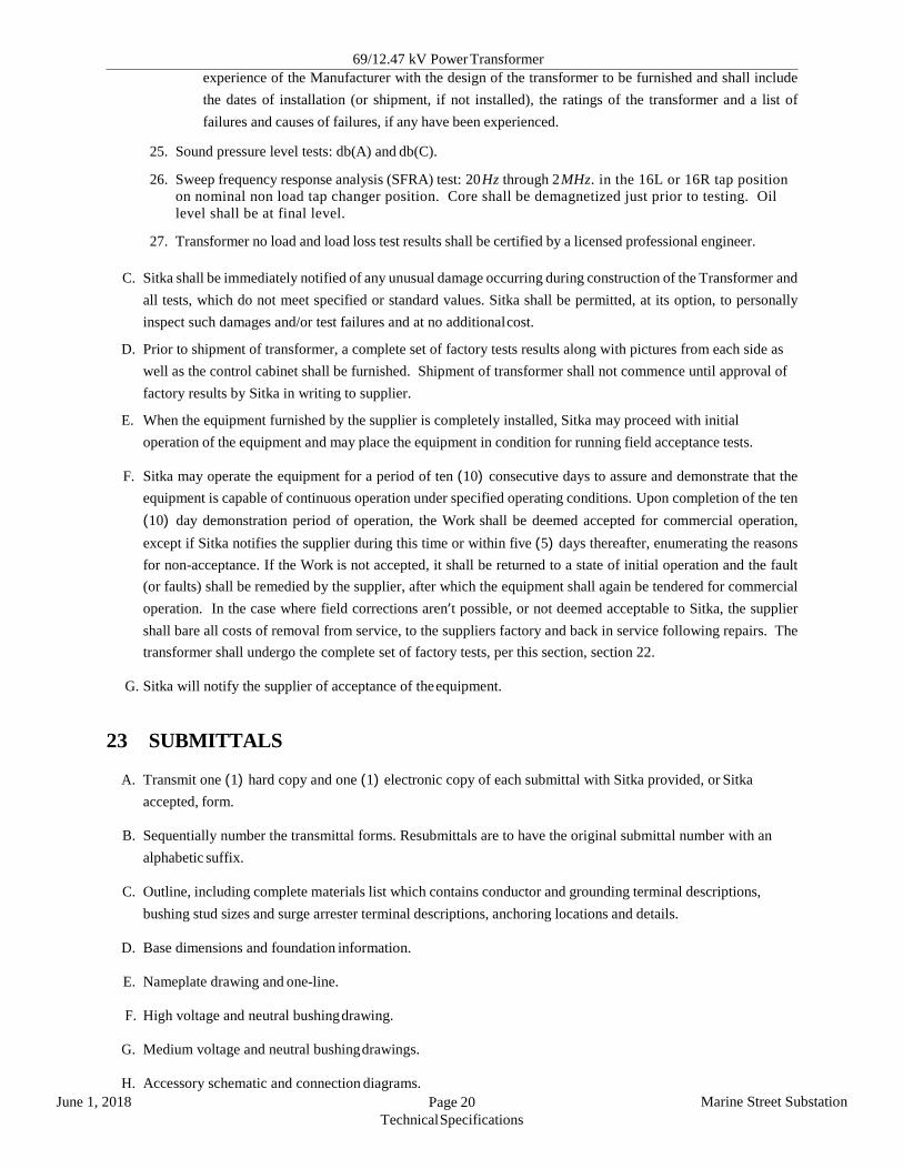
experience of the Manufacturer with the design of the transformer to be furnished and shall include the dates of installation (or shipment, if not installed), the ratings of the transformer and a list of failures and causes of failures, if any have been experienced.
25. Sound pressure level tests: db(A) and db(C).
26. Sweep frequency response analysis (SFRA) test: 20 Hz through 2 MHz. in the 16L or 16R tap position on nominal non load tap changer position. Core shall be demagnetized just prior to testing. Oil level shall be at final level.
27. Transformer no load and load loss test results shall be certified by a licensed professional engineer.
C. Sitka shall be immediately notified of any unusual damage occurring during construction of the Transformer and all tests, which do not meet specified or standard values. Sitka shall be permitted, at its option, to personally inspect such damages and/or test failures and at no additional cost.
D. Prior to shipment of transformer, a complete set of factory tests results along with pictures from each side as well as the control cabinet shall be furnished. Shipment of transformer shall not commence until approval of factory results by Sitka in writing to supplier.
E. When the equipment furnished by the supplier is completely installed, Sitka may proceed with initial operation of the equipment and may place the equipment in condition for running field acceptance tests.
F. Sitka may operate the equipment for a period of ten (10) consecutive days to assure and demonstrate that the equipment is capable of continuous operation under specified operating conditions. Upon completion of the ten (10) day demonstration period of operation, the Work shall be deemed accepted for commercial operation, except if Sitka notifies the supplier during this time or within five (5) days thereafter, enumerating the reasons for non-acceptance. If the Work is not accepted, it shall be returned to a state of initial operation and the fault (or faults) shall be remedied by the supplier, after which the equipment shall again be tendered for commercial operation. In the case where field corrections aren’t possible, or not deemed acceptable to Sitka, the supplier shall bare all costs of removal from service, to the suppliers factory and back in service following repairs. The transformer shall undergo the complete set of factory tests, per this section, section 22.
G. Sitka will notify the supplier of acceptance of the equipment. 23 SUBMITTALS
A. Transmit one (1) hard copy and one (1) electronic copy of each submittal with Sitka provided, or Sitka accepted, form.
B. Sequentially number the transmittal forms. Resubmittals are to have the original submittal number with an alphabetic suffix.
C. Outline, including complete materials list which contains conductor and grounding terminal descriptions, bushing stud sizes and surge arrester terminal descriptions, anchoring locations and details.
D. Base dimensions and foundation information.
E. Nameplate drawing and one-line.
F. High voltage and neutral bushing drawing.
G. Medium voltage and neutral bushing drawings.
H. Accessory schematic and connection diagrams.

69/12.47 kV Power Transformer
June 1, 2018 Page 21 Technical Specifications
Marine Street Substation
I. Control cabinet wiring diagram.
J. Surge arrester drawings.
K. BCT performance curves.
L. Shipping dimensions and weights.
M. Instruction and maintenance manual.
N. Certified NEMA test reports.
O. Certified IEEE Transformer impulse test report.
P. Oil specification and test reports.
Q. Impact recorder charts and chart evaluation .
R. Photographs of each side of the core and coil assembly before tanking of the assembly.
S. Material Safety Data Sheet (MSDS) to comply with OSHA Hazard Communication Standard 29CFR
1910.1200 shall be provided.
T. Submittal Schedule
1. The following documents and drawings shall be submitted for approval within thirty days of receipt of the executed Contract. Submit one (1) hard copy and one (1) electronic copy of approval documents in accordance with Special Provisions Section 8, Submittal Procedure and Requirements.
i. Outline, including complete materials list which contains conductor and grounding terminal descrip- tions, bushing stud sizes and surge arrester terminal descriptions, anchoring locations and details.
ii. Base dimensions and foundation information.
iii. Nameplate drawing and one-line.
iv. High voltage and neutral bushing drawing.
v. Medium voltage and neutral bushing drawings.
vi. Medium voltage cable support drawing
vii. Accessory schematic and connection diagrams.
viii. Control cabinet wiring diagram.
ix. Surge arrester drawings.
x. BCT performance curves.
xi. Shipping dimensions and weights.
2. The following final documents, as-built drawings, and additional information shall be submitted two weeks prior to scheduled equipment delivery. Submit one (1) hard copy and one (1) electronic copy of final documents, as-built drawings, and additional information in accordance with Special Provisions Section 8, Submittal Procedure and Requirements.
i. All documents specified in item (1) above.
ii. Instruction and maintenance manual.

69/12.47 kV Power Transformer
June 1, 2018 Page 22 Technical Specifications
Marine Street Substation
iii. Certified NEMA test reports.
iv. Certified IEEE Transformer impulse test report.
v. Oil specification and test reports.
vi. Photographs of each side of the core and coil assembly before tanking of the assembly. vii. Material Safety Data Sheet (MSDS) to comply with OSHA Hazard Communication Standard 29CFR
1910.1200 shall be provided.
viii. Impact recorder data/charts and data/chart evaluation. 24 PACKING FOR SHIPMENT
A. The equipment and appurtenances shall be packed and protected against rough handling and
corrosion due to exposure to marine atmosphere, exposure to dust or to open storage after acceptance of final test results.
B. Contractor shall be solely responsible for the adequacy of the packaging of equipment and for the furnishing and delivering of undamaged equipment to the delivery site.
C. Packages shall have international markings indicating “This Side Up”, “Fragile”, “Use No Hooks”, etc., as required. The center of gravity shall be plainly marked on all sides of each package when applicable.
D. The equipment shall be shipped assembled to the greatest extent possible. In its proposal, the Contractor shall indicate the shipping arrangements and the required field assembly.
E. All oil that is shipped outside of the transformer and that is required for filling on site prior to energization shall be sent in a single bulk tank. The supplier shall indicate the anticipated volume of the oil to be transferred on site in their proposal.
F. Due to restrictions at the site, the maximum acceptable ship weight for any component of the transformer is limited to 90,000 lbs. The Contractor shall indicate expected shipping weights of all components in their proposal.
G. Two digital impact recorders furnished by the supplier shall be properly packaged, oriented, and attached to the Transformer. The recorders shall indicate impacts separately on two axis and the data/charts shall be stamped adequately to determine the date, time, and location of severe impacts. Impact recorders furnished by the transportation company are not acceptable. The recorders shall be placed in operation before the Transformer begins shipment and shall remain attached and in operation until the Transformer has been offloaded at Sitka’s site. If impact recorders or indications of damage due to impact are detected the supplier shall perform a Doble SFRA test at the delivery site to compare with the factory Doble SFRA test to determine if any damage or shifting of internal components has occurred. Doble SFRA testing shall be required if an impact greater than 3g’s in any direction is detected by either of the impact recorders. Impact recorder data shall be downloaded from the two impact recorders and analyzed prior to offloading and acceptance of the Transformer. On-line access to continuous GPS stamped location of Transformer with impact data shall be provided to Sitka once the Transformer is shipped from the factory.

69/12.47 kV Power Transformer
June 1, 2018 Page 23 Technical Specifications
Marine Street Substation
25 TECHNICAL EVALUATION SHEET
A. All Contractors submitting a bid under this specification shall complete the fields in Tables III through VII and submit it with their bid.

69/12.47 kV Power Transformer
June 1, 2018 Page 24 Technical Specifications
Marine Street Substation
Table III: Technical Evaluation Sheet Description Units Spec Data Vendor Data Transformer Manufacturer - By Manufacturer LTC Manufacturer/Model No. - By Manufacturer Transformer Quantity - 1 Electrical Data
Maximum Voltage kVL−L 72.5 Nominal High Voltage Primary kVL−L 69 Nominal Medium Voltage Secondary kVL−L 12.47 Nominal Frequency Hz 60 ONAN/ONAF 65ºC Capacity Rating MVA 15/20/25
Insulating Liquid Manufacturer - By Manufacturer Type - Uninhibited Mineral Oil Dielectric Strength kV By Manufacturer
Dielectric Tests Applied Voltage, H Winding kV By Manufacturer Applied Voltage, X Winding kV By Manufacturer Induced Voltage, 3φ , 1 hr, Line to Line kV By Manufacturer Induced Voltage, 3φ , 1 hr, Line to Ground kV By Manufacturer
Basic Impulse Level H Phase Windings kV 350 H Neutral Winding kV 350 X Phase Windings kV 110 X Neutral Winding kV 110
Percent Regulation at 100% Power Factor % By Manufacturer Percent Regulation at 80% Power Factor % By Manufacturer Percent Exciting Current at 100% Voltage % By Manufacturer Percent Exciting Current at 105% Voltage % By Manufacturer AC Supply Voltage VAC 120/240VAC @ 60 Hz DC Supply Voltage VDC 125 High & Medium Voltage Winding Material - Copper Winding Configuration (Circular, Rectangular, Cruciform) - By Manufacturer Mechanical Data
Height (Main Tank / Overall) in By Manufacturer Width (Main Tank / Overall) in By Manufacturer Depth (Main Tank / Overall) in By Manufacturer Net Weight lbs By Manufacturer Shipping Weight lbs By Manufacturer High Seismic IEEE 693-2005 Certified - Yes Are any Special Tools Required? - By Manufacturer Will Equipment Ship Completely Assembled? - By Manufacturer Are Radiators Shipped Assembled on Transformers? - By Manufacturer Are Bushings Shipped Assembled on Transformer? - By Manufacturer Are Fans Shipped Assembled on Transformer? - By Manufacturer Is Mfgr’s Rep. Required for Installation? - By Manufacturer Volume of Oil to be Installed after Delivery gal By Manufacturer Is Oil and Filling Included with Bid Price - By Manufacturer
Manufacturing Data Manufacturing Plant Location - By Manufacturer Warranty Duration months By Manufacturer
Delivery Method of Shipment (truck, rail, etc.) - By Manufacturer No. of Days Exceeding Specified Delivery Date - By Manufacturer Total No. of Weeks from NTP weeks By Manufacturer Freight Terms - FOB Destination, Freight Prepaid and Allowed Delivery Destination - Sitka’s Marine Street Substation Transformer
Foundation, Sitka, AK Schedule of Submissions
Submittal of Review Drawings Weeks By Manufacturer Manufacturing Time Weeks By Manufacturer Drawings and Additional Information Weeks By Manufacturer Final Documents and As-Builts Weeks By Manufacturer Impact Recorder Charts and Evaluations Weeks By Manufacturer

69/12.47 kV Power Transformer
June 1, 2018 Page 25 Technical Specifications
Marine Street Substation
Table IV: Bid Evaluation Sheet
Table V: Guaranteed Losses
Table VI: Auxiliary Losses & Sound Levels
Transformer Auxiliary Losses Sound Level MVA Losses With Auxiliaries Without Auxiliaries 15
Watts dB(A) dB(C) dB(A) dB(C) 20 Watts dB(A) dB(C) dB(A) dB(C) 25 Watts dB(A) dB(C) dB(A) dB(C)
Table VII: Impedance Data Percent Impedance Between Windings
Winding 15 MVA 20 MVA 25 MVA H-X (R1 + jX 1) % % % H-X (R0 + jX 0) % % %
Description Vendor Data Weeks late past requested delivery date x $4,000 per week $ No Load Loss (LNL) = kW × $4,000/kW $ kW of Loss at 15 MVA (L15) = kW × 0.3 × $4,000/kW $ kW of Loss at 20 MVA (L20) = kW × 0.1 × $4,000/kW $ kW of Loss at 25 MVA (L20) = kW × 0.1 × $4,000/kW $ Oil Installation (if not part of bid price) @ $50 per gallon $ Total $
Excitation Voltage No Load Load at 15 MVA (ONAN) Total Accuracy 100% Watts Watts Watts ± % 110% Watts Watts Watts ± %
Excitation Voltage No Load Load at 20 MVA (ONAF) Total Accuracy
100% Watts Watts Watts ± % 110% Watts Watts Watts ± %
Excitation Voltage No Load Load at 25 MVA (ONAF) Total Accuracy
100% Watts Watts Watts ± % 110% Watts Watts Watts ± %

69/12.47 kV Power Transformer
June 1, 2018 Page 26 Technical Specifications
Marine Street Substation
26 PRODUCT DATA SHEETS

69/12.47 kV Power Transformer
June 1, 2018 Page 27 Technical Specifications
Marine Street Substation

69/12.47 kV Power Transformer
June 1, 2018 Page 28 Technical Specifications
Marine Street Substation