Embed Size (px)
Citation preview

THIS DOCUMENT CONTAINS PROPRIETARY INFORMATION OF ALTEA B.V. NOT DISCLOSABLE, NOT REPRODUCIBLE. ALL RIGHTS RESERVED Altea B.V. – Hoogoorddreef 15, 1101 BA Amsterdam, The Netherlands
Date: 12/03/2017
Customer : N/A Ref. No.
N/A
Device Under Test: ALTEA VS-
24-I
REV.
1
Page
1/19
TECHNICAL SPECIFICATIONS
VOLTAGE LOW-POWER TRANSFORMER
VS-24-I
Rev. Date Revision
Description Prepared by Checked by Approved by
0 24/09/12 First issue A. Peretto L. Peretto 1 24/06/16 All text review E. Scala L. Peretto J. L. Kennedy
THIS DOCUMENT CONTAINS PROPRIETARY INFORMATION OF ALTEA B.V. NOT DISCLOSABLE, NOT REPRODUCIBLE. ALL RIGHTS RESERVED Altea B.V. – Hoogoorddreef 15, 1101 BA Amsterdam, The Netherlands
Date: 12/03/2017
Customer : N/A Ref. No.
N/A
Device Under Test: ALTEA VS-
24-I
REV.
1
Page
2/19
INDEX
1. SCOPE OF THE DOCUMENT 4
2. VS-24-I DESCRIPTION 4
3. REFERENCE DOCUMENTS 6
4. OPERATIONAL CHARACTERISTICS of ALTEA VS-24-I 6
5. SERVICE CONDITIONS OF THE ALTEA VS-24-I 6
5.1 Service conditions 6
5.1.1 Ambient air temperature 6
5.1.2 Altitude 6
5.1.3 Vibration and earth tremors 7
5.1.4 Service conditions for the ALTEA VS-24-I 7
5.2 Earthing system 7
5.3 Materials 7
5.4 Safety 10
6. RATING OF THE LOW-POWER VOLTAGE TRANSFORMER VS-24-I 10
6.1 Standard values of rated voltages 10
6.1.1 Rated primary voltage 10
6.1.2 Rated secondary voltage 10
6.2 Standard values of rated voltage factor ku 10
6.2.1 Earthed low-power voltage transformer 10
6.2.2 Unearthed low-power voltage transformer 10
6.3 Standard values of rated auxiliary power supply voltage 10
6.4 Standard reference values of other influencing parameters 10
6.4.1 Standard reference range of frequency 10
6.4.2 Standard reference range of auxiliary power supply voltage 10
6.4.3 Standard reference range of burden 10
6.4.4 Standard reference range of temperature 10
7. DESIGN FEATURES OF THE LOW-POWER VOLTAGE TRANSFORMER
VS-24-I 11
7.1 Insulation requirements for primary voltage 11
7.1.1 Rated insulation levels for primary terminals 11
7.1.2 Power-frequency withstand voltage 11
7.1.3 Lightning impulse capability 11
7.1.4 Power-frequency withstand voltage for earthed terminal 11
7.1.5 Partial discharges 11
7.1.6 Chopped lightning impulse 11
7.1.7 Capacitance and dielectric dissipation factor 11
THIS DOCUMENT CONTAINS PROPRIETARY INFORMATION OF ALTEA B.V. NOT DISCLOSABLE, NOT REPRODUCIBLE. ALL RIGHTS RESERVED Altea B.V. – Hoogoorddreef 15, 1101 BA Amsterdam, The Netherlands
Date: 12/03/2017
Customer : N/A Ref. No.
N/A
Device Under Test: ALTEA VS-
24-I
REV.
1
Page
3/19
7.2 Insulation requirements for low-voltage components 11
7.2.1 Power-frequency voltage withstand capability 11
7.2.2 Impulse voltage withstand capability 11
7.3 Short-circuit withstand capability 12
7.4 Limits of temperature rise 12
7.4.1 General requirements 12
7.5 Radio interference voltage requirements 12
7.6 Transmitted overvoltage requirements 12
7.7 Electromagnetic compatibility requirements 12
7.7.1 Emission requirements 12
7.7.2 Immunity requirements 13
7.8 Reliability 13
7.9 Abnormal conditions withstand capability 13
7.10 Abnormal condition signalling 13
7.11 Mechanical requirements 13
7.12 Earthing terminals 13
7.12.1 Earthing of the primary voltage and primary converter 14
7.12.2 Earthing of the secondary converter 14
8. CLASSIFICATION OF TESTS 14
8.1 Type tests 14
8.2 Routine tests 14
8.3 Special tests 14
8.4 Type tests for indoor post insulator installation 15
8.5 Sample tests for indoor post insulator installation 15
8.6 Routine test indoor installation 15
9. MARKINGS 16
9.1 Rating plate markings 16
9.2 Terminals markings 16
9.2.1 Connector type RJ45 16
9.3 Record of Insulator 16
9.4 Maintenance requirement 17
10. ACCURACY FOR SINGLE-PHASE ALTEA VS-24-I ELECTRONIC
MEASURING VOLTAGE TRANSFORMER 17
11. ADDITIONAL REQUIREMENTS FOR SINGLE-PHASE ELECTRONIC
PROTECTIVE VOLTAGE TRANSFORMERS 18
11.1 Standard accuracy classes for electronic protective voltage transformers 18
11.2 Transient performance requirements 18
11.2.1 Primary short circuit 18
11.3 Opening on a line 18
11.4 Reclosing on a line with trapped charges 18

THIS DOCUMENT CONTAINS PROPRIETARY INFORMATION OF ALTEA B.V. NOT DISCLOSABLE, NOT REPRODUCIBLE. ALL RIGHTS RESERVED Altea B.V. – Hoogoorddreef 15, 1101 BA Amsterdam, The Netherlands
Date: 12/03/2017
Customer : N/A Ref. No.
N/A
Device Under Test: ALTEA VS-
24-I
REV.
1
Page
4/19
SCOPE OF THE DOCUMENT
The scope of the present document is the definition of technical characteristics of the Low-Power
Voltage Transformer for indoor use Altea VS-24-I in accordance with reference documents listed in Chapter
3.
1. VS-24-I DESCRIPTION
The device under specification (Fig.1) is a MV low-power voltage transformer. It has the main
electrical and mechanical characteristics listed in the table below. * marks the characteristics that can be set
to different values upon request.
Rated insulation level 24/50/125 kV
Rated primary voltage, Upn * 20/√3 kV
Maximum voltage, Um 24 kV
Rated secondary voltage, Usn * 1 V
Rated voltage factor, Ku 1,9 for 8h
Nominal frequency 50 / 60 Hz
Nominal transformation ratio, Kn * 20/√3 kV / 1 V
Accuracy class * 3P for protection
0.5 for measurements
Accuracy on Harmonics Special Quality metering
Auxiliary Supply voltage ±12 Vdc
Max. Auxiliary Supply current 15 mA
Bandwidth (-3 dB) 100 kHz
Creepage 375 mm
Primary terminal capacity 1 pF
Weight 1,6 kg
Applicable Standards IEC 60044-7, IEC 60660

THIS DOCUMENT CONTAINS PROPRIETARY INFORMATION OF ALTEA B.V. NOT DISCLOSABLE, NOT REPRODUCIBLE. ALL RIGHTS RESERVED Altea B.V. – Hoogoorddreef 15, 1101 BA Amsterdam, The Netherlands
Date: 12/03/2017
Customer : N/A Ref. No.
N/A
Device Under Test: ALTEA VS-
24-I
REV.
1
Page
5/19
Fig.1 – Low-power voltage transformer VS-24-I

THIS DOCUMENT CONTAINS PROPRIETARY INFORMATION OF ALTEA B.V. NOT DISCLOSABLE, NOT REPRODUCIBLE. ALL RIGHTS RESERVED Altea B.V. – Hoogoorddreef 15, 1101 BA Amsterdam, The Netherlands
Date: 12/03/2017
Customer : N/A Ref. No.
N/A
Device Under Test: ALTEA VS-
24-I
REV.
1
Page
6/19
3. REFERENCE DOCUMENTS
The following reference documents were considered for the definition of Altea VS-24-I operational
characteristics:
1. IEC 60044-7 (1999-12) "Instrument transformers - Part 7: Electronic voltage transformers";
2. IEC 60660: Insulators - Tests on Indoor Post Insulators of Organic Material for Systems with Nominal Voltages Greater Than 1 000 V up to but Not Including 300 kV;
3. IEC 60044-8 (2002) "Instrument transformers - Part 8: Electronic current transformers";
4. IEC 60060-1 (2010) “High voltage test techniques – Part 1: General definitions and test requirements”;
5. IEC 60815 (1986) “Guide for the selection of insulator in respect of polluted conditions”
6. IEC 60071-2 (1996) “Insulation co-ordination - Part 2: Application guide”
4. OPERATIONAL CHARACTERISTICS of ALTEA VS-24-I
According to [1], the operational characteristics are collected into six main sessions:
5. Service conditions;
6. Rating,
7. Design features;
8. Test performed;
9. Markings;
10. Accuracy for single-phase Altea VS-24-I electronic measuring voltage transformer;
11. Additional requirements for single-phase Altea VS-24-I electronic protective
voltage transformer.
5. SERVICE CONDITIONS OF THE ALTEA VS-24-I
According to [1 and 2] the low-power voltage transformer Altea VS-24-I is suitable for both
measuring and protection purposes.
5.1 Service conditions
5.1.1 Ambient Air Temperature
The ambient air temperature range is the standard one for indoor applications: [-5; + 40] °C.

THIS DOCUMENT CONTAINS PROPRIETARY INFORMATION OF ALTEA B.V. NOT DISCLOSABLE, NOT REPRODUCIBLE. ALL RIGHTS RESERVED Altea B.V. – Hoogoorddreef 15, 1101 BA Amsterdam, The Netherlands
Date: 12/03/2017
Customer : N/A Ref. No.
N/A
Device Under Test: ALTEA VS-
24-I
REV.
1
Page
7/19
5.1.2 Altitude
For installations at an altitude higher than 1000 m, the arcing distance under the standardized
reference atmospheric conditions is determined by multiplying the withstand voltages required at the
service location by a factor k in accordance with Figure 3 of [1].
5.1.3 Vibrations on earth tremors
Typical vibrations to the low-power voltage transformer due to external causes or earth tremors do
not affect the operation of VS-24-I.
5.1.4 Service conditions for indoor ALTEA VS-24-I
Altea VS-24-I is compliant with the requirements of [1, 4.1.4] regarding the service conditions for
indoor use:
Table 5.1
Solar radiation Negligible
Humidity and water vapour
1) the average value of the relative
humidity, measured during a period of
24 h does not exceed 95 %;
2) the average value of the relative
humidity for a period of one month does
not exceed 90 %;
3) the average value of the water
vapour pressure for a period of 24 h
does not exceed 2,2 kPa;
4) the average value of the water
vapour pressure for a period of one
month does not exceed 1,8 kPa.
5.2 Earthing system [1, 4.3]
The Altea VS-24-I is an earthed low-power voltage transformer. The output voltage of the Altea
VS-24-I is representative of the phase to ground primary voltage.
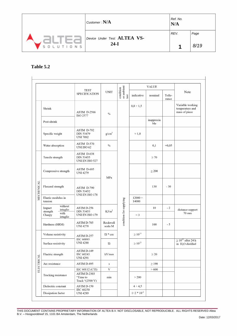
5.3 Material
The Altea VS-24-I is epoxy resin material named EA-2470/NA whose features are reported in
Table 5.2.
THIS DOCUMENT CONTAINS PROPRIETARY INFORMATION OF ALTEA B.V. NOT DISCLOSABLE, NOT REPRODUCIBLE. ALL RIGHTS RESERVED Altea B.V. – Hoogoorddreef 15, 1101 BA Amsterdam, The Netherlands
Date: 12/03/2017
Customer : N/A Ref. No.
N/A
Device Under Test: ALTEA VS-
24-I
REV.
1
Page
8/19
Table 5.2

THIS DOCUMENT CONTAINS PROPRIETARY INFORMATION OF ALTEA B.V. NOT DISCLOSABLE, NOT REPRODUCIBLE. ALL RIGHTS RESERVED Altea B.V. – Hoogoorddreef 15, 1101 BA Amsterdam, The Netherlands
Date: 12/03/2017
Customer : N/A Ref. No.
N/A
Device Under Test: ALTEA VS-
24-I
REV.
1
Page
9/19
TEST
SPECIFICATION UNIT
VALUE
Note
indicative nominal **
Tollerance
Specific heat j
kg * °C
Thermal conductivity ASTM D-2303 DIN 53612
UNI 4289
W
m * °C
0,6 ÷ 0,9
Coefficient of linear
thermal expansion ASTM D-696
UNI 6061 ° C-1 ≈ 4 * 10-5
Index of temperature
( 50% flexural
resistance 20000 h) IEC 60216
DIN 53446
° C
130 -6
Glass transition
temperature IEC 61006 110 +10 -5
Heat deformation
resistance according to
Martens DIN 53458
UNI 4281 100 +15 -0
Flammability
temperature DIN 51584 > 250
of sample Glow resistance
ASTM igniz. s
D-229
Met. II spegn.
finished
piece IEC 60695
positive result
Optical density
max ASTM E 662
Acid alogenidric
gaseous CEI 20-37 Parte I mg/g absent
index of tosicity CEI 20-37 Parte II
Action resistance of
micro-organisms ASTM G21-G22 good
Resistance of oils, solvents, detergents, hot and cold water
good

THIS DOCUMENT CONTAINS PROPRIETARY INFORMATION OF ALTEA B.V. NOT DISCLOSABLE, NOT REPRODUCIBLE. ALL RIGHTS RESERVED Altea B.V. – Hoogoorddreef 15, 1101 BA Amsterdam, The Netherlands
Date: 12/03/2017
Customer : N/A Ref. No.
N/A
Device Under Test: ALTEA VS-
24-I
REV.
1
Page
10/19
5.4 Safety
The Low-power voltage transformer Altea VS-24-I has an intrinsically safe failure mode. In case of
failure, avoids explosive shattering of the housing. The Supplier is able to provide sufficient service
experience evidence to support a particular design is not associated with brittle fracture problems.
6. RATING OF THE LOW-POWER VOLTAGE TRANSFORMER VS-24-I
6.1 Standard values of rated voltages [1, 5.1]
6.1.1 Rated primary voltage
The Altea-VS-24-I operates with rated primary voltage values from 6 to 20/√3 kV.
6.1.2 Rated secondary voltage
The Altea-VS-24-I rated output voltage is 1 V.
6.2 Standard values of rated voltage factor ku [1, 5.3]
6.2.1 Earthed low-power voltage transformers The
voltage factor of the Altea VS-24-I is 1,9.
6.2.2 Unearthed low-power voltage transformers N/A
for Altea VS-24-I.
6.3 Standard values of rated auxiliary power supply voltage [1, 5.4]
Power supply voltage for the Altea VS-24-I is 12 Vdc.
6.4 Standard reference values of other influencing parameters [1, 5.5]
6.4.1 Standard reference range of frequency
The accuracy class of the Altea VS-24-I is assured for frequencies ranging from 99 % to 101 % of
the rated frequency for measurements purposes and from 96 % to 102 % for protection purposes.
6.4.2 Standard reference range of auxiliary power supply voltage
The accuracy class of the Altea VS-24-I is assured for auxiliary power supply ranging from 90 % to
110 % of the rated auxiliary power supply voltage.

THIS DOCUMENT CONTAINS PROPRIETARY INFORMATION OF ALTEA B.V. NOT DISCLOSABLE, NOT REPRODUCIBLE. ALL RIGHTS RESERVED Altea B.V. – Hoogoorddreef 15, 1101 BA Amsterdam, The Netherlands
Date: 12/03/2017
Customer : N/A Ref. No.
N/A
Device Under Test: ALTEA VS-
24-I
REV.
1
Page
11/19
6.4.3 Standard reference range of burden
The accuracy class of the Altea VS-24-I is assured for load impedances above 100 k .
6.4.4 Standard reference range of temperature
The standard reference range of ambient air temperature is from -5 to +40 °C.
7. DESIGN FEATURES OF THE LOW-POWER VOLTAGE TRANSFORMER
VS-24-I
7.1 Insulation requirements for primary voltage [1, 6]
7.1.1 Rated insulation levels for primary terminals
The rated insulation level of the primary voltage of VS-24-I is 24 kV.
7.1.2 Power-frequency withstand voltage Power-frequency
withstand voltage is 50 kV.
7.1.3 Lightning impulse capability
The lighting impulse capability is 125 kV.
7.1.4 Power-frequency withstand voltage for earthed terminal
The terminal of the primary voltage sensor intended to be earthed must, when insulated from the
case or frame, be capable of withstanding a rated power-frequency short-duration withstand voltage of 3
kV (r.m.s.) for 1 min.
N/A for Altea VS-24-I since one of the input terminals is connected to ground and to the case.
7.1.5 Partial discharges
The Altea VS-24-I features partial discharge levels are below 50 pC at 28,8 kV (equal to 1,2 24)
and below 20 pC at 16,6 kV (equal to 1,2 24/√3). Partial Discharge extinction level is 15,2 kV (equal to
1,1 24/√3).
7.1.6 Chopped lightning impulse
If additionally specified, the primary voltage terminals shall also be capable of withstanding a
chopped lightning-impulse voltage which has a peak value of 115 % of the full lightning-impulse voltage.
N/A for Altea VS-24-I.

THIS DOCUMENT CONTAINS PROPRIETARY INFORMATION OF ALTEA B.V. NOT DISCLOSABLE, NOT REPRODUCIBLE. ALL RIGHTS RESERVED Altea B.V. – Hoogoorddreef 15, 1101 BA Amsterdam, The Netherlands
Date: 12/03/2017
Customer : N/A Ref. No.
N/A
Device Under Test: ALTEA VS-
24-I
REV.
1
Page
12/19
7.1.7 Capacitance and dielectric dissipation factor
These requirements apply only to low-power voltage transformers with liquid-immersed
primary voltage sensor insulation having Um ≥ 72,5 kV. N/A for Altea VS-24-I.
7.2 Insulation requirements for low-voltage components [1, 6.2] Available
upon special customer request.
This insulation shall meet the following requirements:
7.2.1 Power-frequency voltage withstand capability
Withstand voltage level: 2,8 kV r.m.s.
7.2.2 Impulse voltage withstand capability
Withstand voltage level: 5 kV.
7.3 Short-circuit withstand capability [1, 6.3]
Altea VS-24-I is capable of withstanding short circuit between secondary voltage terminals for the
duration of 60 s, when energized at rated voltage.
7.4 Limits of temperature rise [1, 6.4]
7.4.1 General requirements
Altea VS-24-I withstands the thermal effects caused by the following conditions:
– maximum specified ambient temperature (+ 40 °C);
– rated frequency (50/60 Hz);
– 1,2 times the rated primary voltage [1,2 20/ 3 = 13,85 kV];
– the combination of auxiliary power supply voltage and secondary burden which causes the
maximum internal power dissipation of the secondary converter (±12 V power supply and 5 k
minimum load impedance value).
7.5 Radio interference voltage requirements [6.5]
The purpose of the radio interference voltage test is to verify the emission of corona discharges
created by the low-power voltage transformer. The main cause of corona discharges are high-voltage
parts and partial discharges at the surface of the insulator housing. This test is relevant for low-power
voltage transformers having Um ≥ 123 kV. N/A for Altea VS-24-I.

THIS DOCUMENT CONTAINS PROPRIETARY INFORMATION OF ALTEA B.V. NOT DISCLOSABLE, NOT REPRODUCIBLE. ALL RIGHTS RESERVED Altea B.V. – Hoogoorddreef 15, 1101 BA Amsterdam, The Netherlands
Date: 12/03/2017
Customer : N/A Ref. No.
N/A
Device Under Test: ALTEA VS-
24-I
REV.
1
Page
13/19
7.6 Transmitted overvoltage requirements [1, 6.6]
Alta VS-24-I is protected against the emissions of overvoltages transmitted from the primary to the
secondary output or to the power supply.
7.7 Electromagnetic compatibility requirements [1, 6.7]
Altea VS-24-I is in compliance with all the requirements reported in [1], both concerning the
immunity and emissions. In particular the following tests have been carried out and passed.
7.7.1 Emission requirements
7.7.2 Immunity requirements
- Harmonic and interharmonic disturbance
- Slow voltage variation
- Voltage dips and short interruptions
- Surge immunity
- Electrical fast transient / burst
- Oscillatory wave immunity
- Electrostatic discharge
- Power frequency magnetic field immunity
- Pulse magnetic field immunity
- Damped oscillatory magnetic field immunity
- Radiated radio-frequency electromagnetic field immunity.
7.8 Reliability [1, 6.8]
The estimated MTTF of the Altea VS-24-I is 250.000 h.
7.9 Abnormal conditions withstand capability [1, 6.9]
Depending on the technology used, the short-circuit withstand capability and overheating withstand
capability only apply to the secondary converter.
N/A for Altea VS-24-I.

THIS DOCUMENT CONTAINS PROPRIETARY INFORMATION OF ALTEA B.V. NOT DISCLOSABLE, NOT REPRODUCIBLE. ALL RIGHTS RESERVED Altea B.V. – Hoogoorddreef 15, 1101 BA Amsterdam, The Netherlands
Date: 12/03/2017
Customer : N/A Ref. No.
N/A
Device Under Test: ALTEA VS-
24-I
REV.
1
Page
14/19
7.10 Abnormal condition signalling [1, 6.10]
Altea VS-24-I is designed in order to avoid spurious tripping of protective relays in presence of
impulse voltages.
7.11 Mechanical requirements [1, 6.11]
These requirements apply only to low-power voltage transformers which have a highest voltage for
equipment of 72,5 kV and above.
N/A for Altea VS-24-I.
7.12 Earthing terminals [1, 6.12]
7.12.1 Earthing of the primary voltage and primary converter
Altea VS-24-I is earthed thought the two clamping screws with diameter of 10 mm (see Fig. 1).
7.12.2 Earthing of the secondary converter N/A
for Altea VS-24-I.
8. CLASSIFICATION OF TESTS
In the following the Type tests and Routine tests performed for Altea VS-24-I are listed.
8.1 Type tests [1, 7.1]
a) lightning impulse test [1, 8.1.2];
b) switching impulse test [1, 8.1.3];
c) wet test for outdoor type low-power voltage transformers [1, 8.2]; N/A for Altea VS-24-S.
d) tests for accuracy [1, 8.3];
e) abnormal conditions withstand capability test [1, 8.4]; N/A for Altea VS-24-S.
f) radio interference voltage test [1, 8.5]; N/A for Altea VS-24-S.
g) transmitted overvoltage test [1, 8.6]; N/A for Altea VS-24-S.
h) electromagnetic compatibility tests: emission [1, 8.7.1]
i) electromagnetic compatibility tests: immunity [1, 8.7.2]
j) impulse voltage withstand test for low-voltage components [1, 8.8]
k) transient performance test [1, 8.9]:
- primary short-circuit [1, 8.9.1];

THIS DOCUMENT CONTAINS PROPRIETARY INFORMATION OF ALTEA B.V. NOT DISCLOSABLE, NOT REPRODUCIBLE. ALL RIGHTS RESERVED Altea B.V. – Hoogoorddreef 15, 1101 BA Amsterdam, The Netherlands
Date: 12/03/2017
Customer : N/A Ref. No.
N/A
Device Under Test: ALTEA VS-
24-I
REV.
1
Page
15/19
- reclosing on a line with trapped charges [1, 8.9.2];
N/A for Altea VS-24-I.
8.2 Routine tests [1, 7.2]
a) verification of terminal markings [1, 9.1]
b) power-frequency withstand tests on primary voltage terminals [1, 9.2]
c) partial discharge measurement [1, 9.2.4];
d) power-frequency voltage withstand test for low-voltage components [1, 9.3] Only on
insulators with sensor equipped with galvanic insulation.
e) tests for accuracy [1, 9.4]
8.3 Special tests [1, 7.3] *
a) chopped lightning-impulse test on primary voltage terminals [1, 10.1];
b) measurement of capacitance and dielectric dissipation factor [1, 10.2];
c) mechanical strength tests [1, 10.3];
* To be performed on client request.
In addition, for post insulators of organic material for indoor service in electrical
installations or equipment operating in air at atmospheric pressure on alternating current
with a nominal voltage greater than 1 000 V up to, but lower than 300 kV, test foreseen by
the standard [2] are applied.
8.4 Type tests for indoor post insulator installation [2, 3]
a) water absorption test [2, 3.10];
b) flammability test [2, 3.12];
c) ageing and humidity test [2, 3.11].
d) test for mechanical bending strength as a function of temperature [2, 3.9];
e) dry lightning impulse withstand voltage test [2, 3.3];
(covered by test a) of Type tests)
f) dry power-frequency withstand voltage test [2, 3.4];
g) lightning impulse puncture test [2, 3.6];
h) temperature cycle test [2, 3.13];
i) partial discharge extinction voltage test [2, 3.5];
j) test for deflection under load at normal ambient temperature conditions [2, 3.8];
k) mechanical failing load test (bending test, tensile test, torsion test, compres. test) [2, 3.7].

THIS DOCUMENT CONTAINS PROPRIETARY INFORMATION OF ALTEA B.V. NOT DISCLOSABLE, NOT REPRODUCIBLE. ALL RIGHTS RESERVED Altea B.V. – Hoogoorddreef 15, 1101 BA Amsterdam, The Netherlands
Date: 12/03/2017
Customer : N/A Ref. No.
N/A
Device Under Test: ALTEA VS-
24-I
REV.
1
Page
16/19
8.5 Sample tests for indoor post insulator installation [2, 4]
The samples shall then be subjected to the following tests in the order given: a)
verification of dimensions [2, see 4.2];
b) water absorption test for materials other than cast epoxy resin or PUR resin only [2, 3.10];
c) partial discharge extinction voltage test [2, 3.5];
(covered by test c) of Routine tests)
d) test for deflection under load at normal ambient temperature conditions [2, 3.8] *;
e) test for mechanical strength at normal ambient temperature conditions [2, 3.7] *.
* To be performed on client request.
8.6 Routine tests for indoor installation [2, 5]
a) visual examination [2, 5.2];
b) mechanical routine test for insulators of design category A; for insulators intended to be
used at rated voltage 72,5 kV and above only [2, 5.3]; N/A for Altea VS-24-I.
c) electrical routine test and partial discharge measurement for post insulators of design
category B [2, 5.4];
(covered by test c) of Routine tests)
9. MARKINGS [1, 11 – 2, 1.5]
9.1 Rating plate markings
The rating plate of the electronic device is reported in the below figure.
Designation:
Electronic Voltage Transformer
(EVT)
Type: Weight: Serial/year: Ref. Std.:
VS-24-I 1.6 kg 60044-7
Electrical Characteristics Auxiliary Power Supply
Rated Insulation Level = 24/50/125 kV Uar = ±12 V DC

THIS DOCUMENT CONTAINS PROPRIETARY INFORMATION OF ALTEA B.V. NOT DISCLOSABLE, NOT REPRODUCIBLE. ALL RIGHTS RESERVED Altea B.V. – Hoogoorddreef 15, 1101 BA Amsterdam, The Netherlands
Date: 12/03/2017
Customer : N/A Ref. No.
N/A
Device Under Test: ALTEA VS-
24-I
REV.
1
Page
17/19
fr = 50/60 Hz Iar = 10 mA
Ia max = 15 mA
EVT Characteristics
Upr/Usr = 20/3kV / 1V φor = 0 º
Rbr = 100 kΩ ku = 1,9 / 8h
Class 0.5
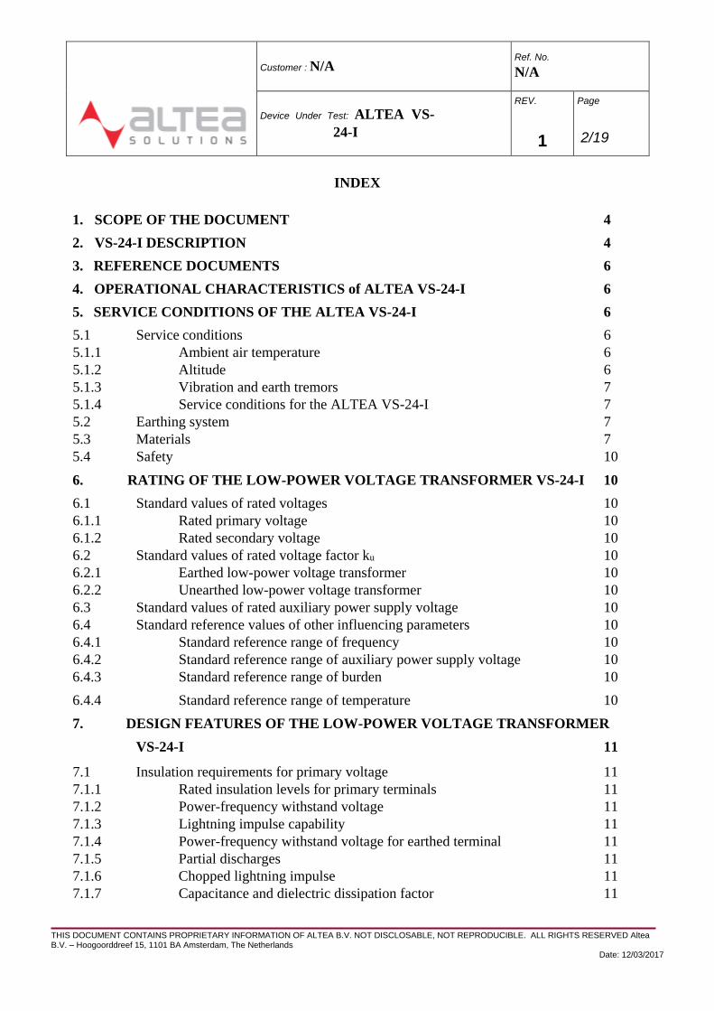
9.2 Terminal markings
9.2.1 Connector type RJ45
Altea BV maintains records of all produced insulators in accordance with this standard for a
minimum of 10 years. These records contains the following information:
– type reference number;
– year of manufacture;
– type tests, date and results; – sample tests, date and results; – routine tests, date and results.
9.4 Maintenance requirement
Altea Low-power voltage transformer Altea VS-I is a disposable device. No sub-parts can be
replaced.
10. ACCURACY FOR SINGLE-PHASE ALTEA VS-24-I ELECTRONIC
MEASURING VOLTAGE TRANSFORMER [1, 12]
1 GND
2 GND
3 GND
4 GND
5 V out
6 V out +
7 + V cc
8 - V SS
9.3 Record of Insul ator
THIS DOCUMENT CONTAINS PROPRIETARY INFORMATION OF ALTEA B.V. NOT DISCLOSABLE, NOT REPRODUCIBLE. ALL RIGHTS RESERVED Altea B.V. – Hoogoorddreef 15, 1101 BA Amsterdam, The Netherlands
Date: 12/03/2017
Customer : N/A Ref. No.
N/A
Device Under Test: ALTEA VS-
24-I
REV.
1
Page
18/19
The low-power voltage transformer Altea VS-24-I is in the Accuracy class 3P for protection and 0,5
for measurement, in the range of temperature ranging from - 25 to + 65 °C.
11. ADDITIONAL REQUIREMENTS FOR SINGLE-PHASE ELECTRONIC
PROTECTIVE VOLTAGE TRANSFORMERS [1, 13]
11.1 Standard accuracy classes for electronic protective voltage transformers
Standard accuracy class for Altea VS-24-I is 3P.
11.2 Transient performance requirements
11.3.1 Primary short circuit
Following a short circuit of the supply between the high-voltage terminal and the low-voltage
terminal connected to earth, the secondary output voltage of Altea VS-24-I will decay, within one cycle
of rated frequency, to a value of less than 10 % of the peak value before short circuit.
11.3 Opening on a line
When opening a line results in a trapped charge, the secondary voltage component Us dc(t) shall
decay to zero in order to prevent saturation of input transformers of the connected equipments. This time
constant must be declared by the manufacturer.
N/A for Altea VS-24-I.
11.4 Reclosing on a line with trapped charges N/A
for Altea VS-24-I.
END OF DOCUMENT

THIS DOCUMENT CONTAINS PROPRIETARY INFORMATION OF ALTEA B.V. NOT DISCLOSABLE, NOT REPRODUCIBLE. ALL RIGHTS RESERVED Altea B.V. – Hoogoorddreef 15, 1101 BA Amsterdam, The Netherlands
Date: 12/03/2017
Customer : N/A Ref. No.
N/A
Device Under Test: ALTEA VS-
24-I
REV.
1
Page
19/19