Embed Size (px)
Citation preview
1 9919-224 Rev. 11112019
Technical Support Line: (952) 985-5675 Email: [email protected]
INSTALLATION INSTRUCTIONS QA1 P/N R110-170, R110-200, R110-250, R210-170, R210-200, R210-250 Rear Coil-Over Suspension System
’63-’72 Chevrolet C10, GMC C15/C1500 Pickup with Rear Coil Spring Suspension
READ ALL INSTRUCTIONS CAREFULLY AND THOROUGHLY PRIOR TO STARTING INSTALLATION. PRODUCTS THAT HAVE BEEN INSTALLED ARE NOT ELIGIBLE FOR RETURN. USE THE PROPER JACKING LOCATIONS. DEATH OR SERIOUS INJURY CAN RESULT IF INSTRUCTIONS ARE NOT CORRECTLY FOLLOWED. A GOOD CHASSIS MANUAL, AVAILABLE AT YOUR LOCAL PARTS STORE, MAY ALSO AID IN YOUR INSTALLATION.
• DISCLAIMER / WARRANTY •
QA1 WARRANTS THAT THE PRODUCTS WILL BE FREE FROM DEFECTS IN MATERIAL AND WORKMANSHIP FOR ONE YEAR FROM DATE OF SALE TO THE ORIGINAL PURCHASER. QA1 MAKES NO OTHER WARRANTY OF ANY KIND, EXPRESS OR IMPLIED. QA1 SHALL HAVE NO OBLIGATION UNDER THE FOREGOING WARRANTY WHERE THE DEFECT IS THE RESULT OF IMPROPER OR ABNORMAL USE, YOUR NEGLIGENCE, VEHICLE ACCIDENT, IMPROPER OR INCORRECT INSTALLATION OR MAINTENANCE, NOR WHEN THE PRODUCT HAS BEEN REPAIRED OR ALTERED IN ANY WAY. QA1’S LIABILITY IN THE CASE OF DEFECTIVE PRODUCTS SUBJECT TO THE FOREGOING WARRANTY SHALL BE LIMITED TO THE REPAIR OR REPLACEMENT, AT QA1’S OPTION, OF THE DEFECTIVE PRODUCTS. THE USER UNDERSTANDS AND RECOGNIZES THAT RACING PARTS, SPECIALIZED STREET ROD EQUIPMENT, AND ALL PARTS AND SERVICES SOLD BY QA1 ARE EXPOSED TO MANY AND VARIED CONDITIONS DUE TO THE MANNER IN WHICH THEY ARE INSTALLED AND USED. QA1 SHALL BEAR NO LIABILITY FOR ANY LOSS, DAMAGE OR INJURY, EITHER TO A PERSON OR TO PROPERTY, RESULTING FROM THE INSTALLATION, DIRECT OR INDIRECT USE OF ANY QA1 PRODUCTS OR INABILITY BY THE BUYER TO DETERMINE PROPER USE OR APPLICATION OF QA1 PRODUCTS. WITH THE EXCEPTION OF THE LIMITED LIABILITY WARRANTY SET FORTH ABOVE, QA1 SHALL NOT BE LIABLE FOR ANY CLAIMS, DEMANDS, INJURIES, DAMAGES, ACTIONS, OR CAUSES OF ACTION WHATSOEVER TO BUYER ARISING OUT OF OR CONNECTED WITH THE USE OF ANY QA1 PRODUCTS. MOTORSPORTS ARE DANGEROUS; AS SUCH, NO WARRANTY OR REPRESENTATION IS MADE AS TO THE PRODUCT’S ABILITY TO PROTECT THE USER FROM INJURY OR DEATH. THE USER ASSUMES THAT RISK!
TOOLS AND SUPPLIES REQUIRED
• Floor Jack • Drill with 3/8” drill bit • Anti-seize • SAE Wrench Set • Ratchet & SAE Socket Set • Four (4) Jack Stands • T114W or T115W Spanner Wrench • Torque Wrench • Grinder or Air Chisel
Pre-Installation Note Installation of this system will reduce the load carrying capably of the vehicle. This system was designed to be installed with the box on the truck.
A grinder and/or air chisel is recommended for removal of the factory rivets.
1970 and earlier trucks will require the rear brake line to be repositioned from the cross member brace to a supplied bracket.
Disassembly Instructions
1. Raise the vehicle and support the frame with jack stands on a stable surface and remove the wheels.
2. With a jack supporting the axle, remove the wheels, shocks and factory springs.
3. Support the axle with another set of jack stands.
4. For ease of installation, the driveshaft should be disconnected from the Figure 1
2 9919-224 Rev. 11112019
rear differential. 5. Disconnect and remove the factory panhard bar from the frame
mount and axle.
6. The factory panhard bar mount on the left side frame rail and the gusset plate direct above the mount can now be removed. Remove the rivets with a grinder and punch and/or an air chisel. See Figure 1.
7. The bottom cross member rivets on the right frame rail to panhard cross will need to be removed.
8. The factory bump stop mounting brackets will need to be removed and will not be reused.
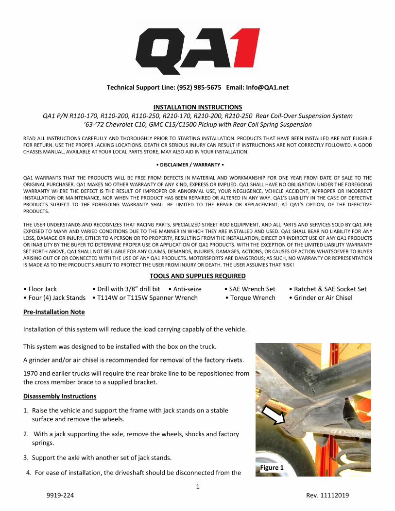
9. Unbolt the truck arm front attachment bolts. Lower the arms down and support with stands. Caution: Do not kink or allow the axle to pull on the brake hose. See Figure 2.
10. Remove the six (6) rivets retaining the each truck arm mounting bracket and remove the brackets from the cross member.
11. Remove the rivets for the shock cross member brace and factory upper spring plate and remove them from the chassis. Do not remove the entire cross member. See Figure 3. The factory upper shock mounts can be removed at this time as well as they will not be reused. Note: 1970 and earlier trucks will require the brake line to be removed from this support and relocated to the QA1 supplied bracket.
Installation Instructions
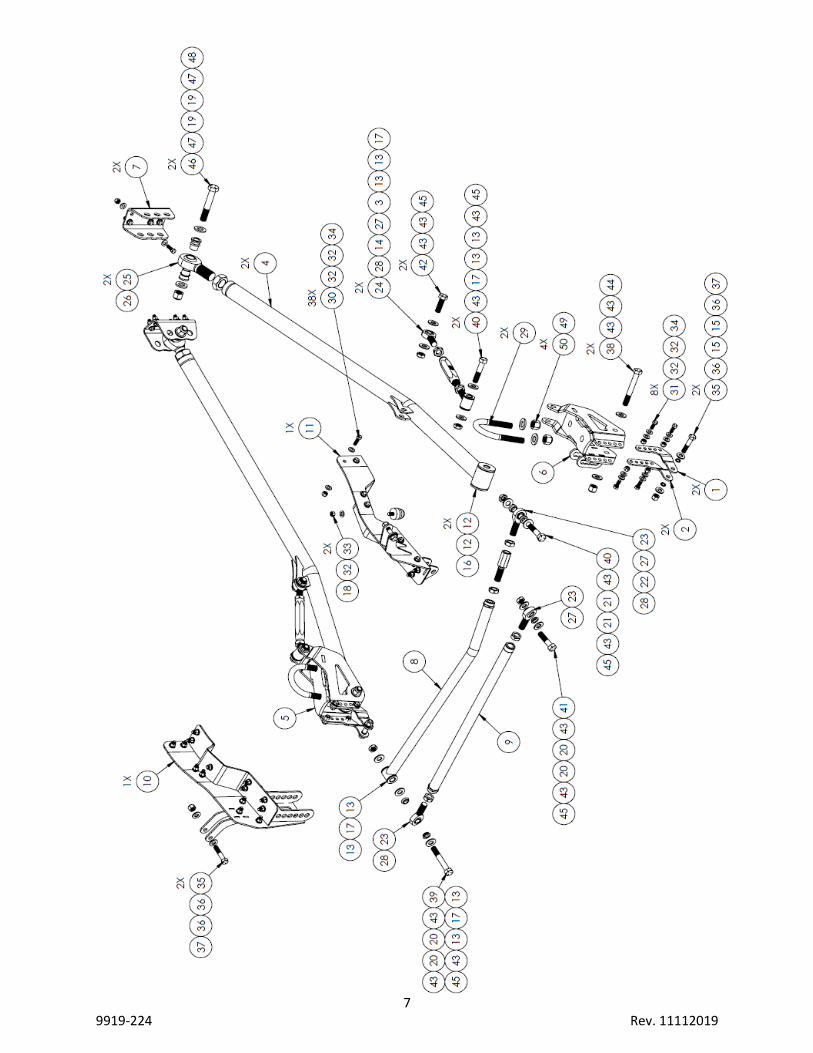
1. Assemble the Panhard bar per the diagram on page 7. Apply anti-seize and thread the rod ends and adjuster all the way in to ensure even thread engagement.
2. Assemble the JNL12S jam nut on XML10-12 rod end and JNR12S jam nut on XMR10-12 rod end. Apply anti-seize and fully thread both rod ends into the panhard bar support brace, P/N 9037-566. See the diagram on page 7.
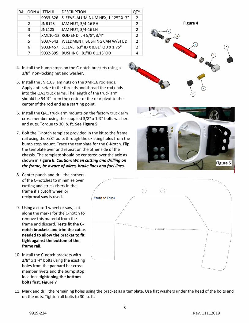
3. Assemble the adjuster links for the QA1 truck arms per Figure 4 with anti-seize on the threads.
Figure 2
Figure 3
3 9919-224 Rev. 11112019
4. Install the bump stops on the C-notch brackets using a 3/8” non-locking nut and washer.
5. Install the JNR16S jam nuts on the XMR16 rod ends. Apply anti-seize to the threads and thread the rod ends into the QA1 truck arms. The length of the truck arm should be 54 ½” from the center of the rear pivot to the center of the rod end as a starting point.
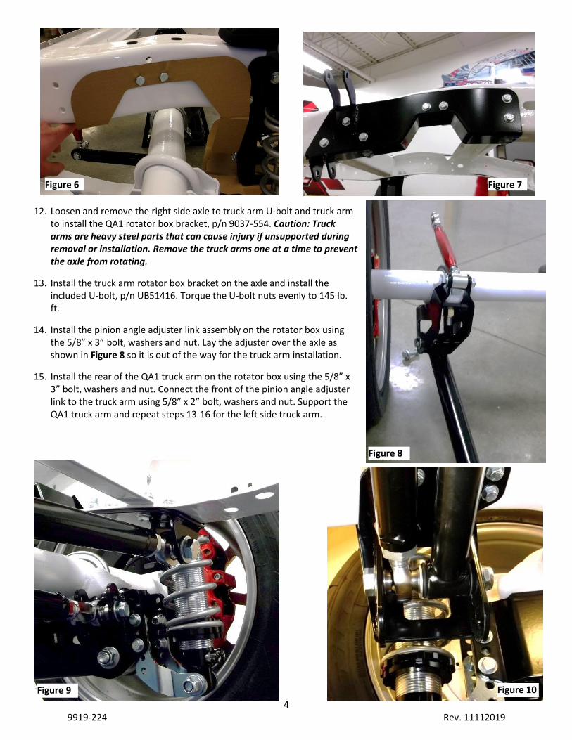
6. Install the QA1 truck arm mounts on the factory truck arm cross member using the supplied 3/8” x 1 ¼” bolts washers and nuts. Torque to 30 lb. ft. See Figure 5.
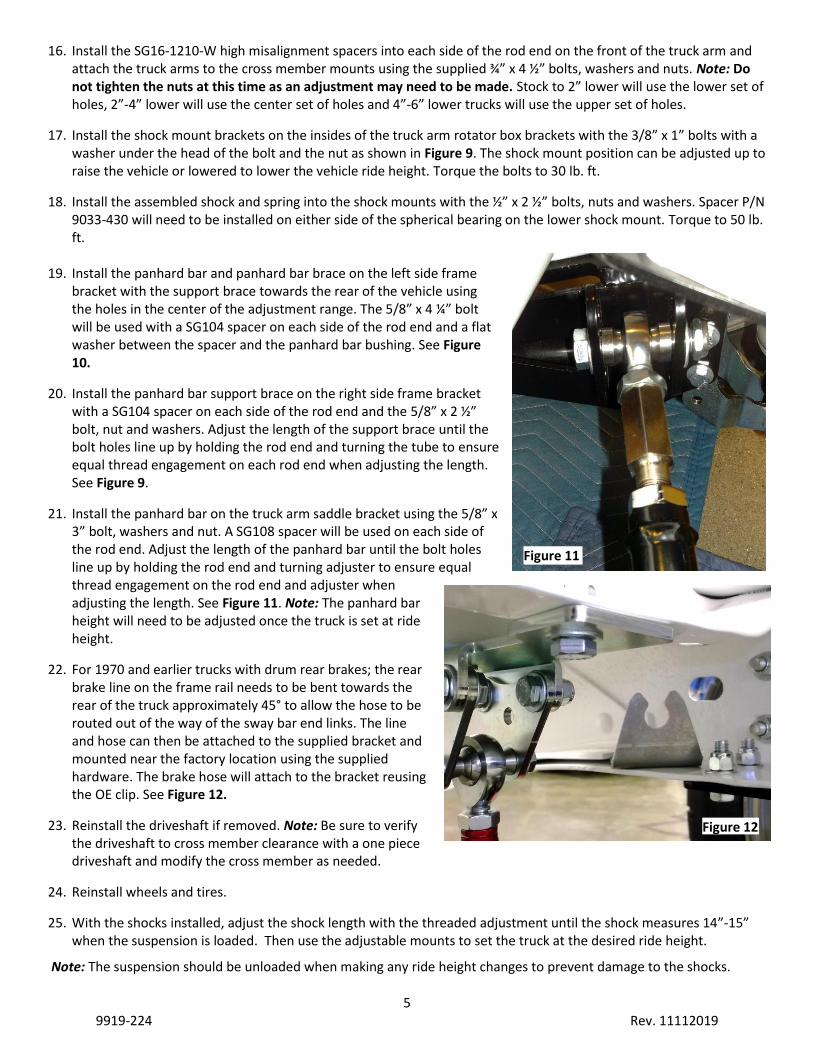
7. Bolt the C-notch template provided in the kit to the frame rail using the 3/8” bolts through the existing holes from the bump stop mount. Trace the template for the C-Notch. Flip the template over and repeat on the other side of the chassis. The template should be centered over the axle as shown in Figure 6. Caution: When cutting and drilling on the frame, be aware of wires, brake lines and fuel lines.
8. Center punch and drill the corners of the C-notches to minimize over cutting and stress risers in the frame if a cutoff wheel or reciprocal saw is used.
9. Using a cutoff wheel or saw, cut
along the marks for the C-notch to remove this material from the frame and discard. Tests fit the C-notch brackets and trim the cut as needed to allow the bracket to fit tight against the bottom of the frame rail.
10. Install the C-notch brackets with 3/8” x 1 ¼” bolts using the existing holes from the panhard bar cross member rivets and the bump stop locations tightening the bottom bolts first. Figure 7
11. Mark and drill the remaining holes using the bracket as a template. Use flat washers under the head of the bolts and on the nuts. Tighten all bolts to 30 lb. ft.
Figure 4
Figure 5
BALLOON # ITEM # DESCRIPTION QTY.
1 9033-326 SLEEVE, ALUMINUM HEX, 1.125" X 7" 2
2 JNR12S JAM NUT, 3/4-16 RH 2
3 JNL12S JAM NUT, 3/4-16 LH 2
4 XML10-12 ROD END, LH 5/8", 3/4" 2
5 9037-543 WELDMENT, BUSHING CAN W/STUD 2
6 9033-457 SLEEVE .63" ID X 0.81" OD X 1.75" 2
7 9032-395 BUSHING, .81"ID X 1.13"OD 4
4 9919-224 Rev. 11112019
12. Loosen and remove the right side axle to truck arm U-bolt and truck arm to install the QA1 rotator box bracket, p/n 9037-554. Caution: Truck arms are heavy steel parts that can cause injury if unsupported during removal or installation. Remove the truck arms one at a time to prevent the axle from rotating.
13. Install the truck arm rotator box bracket on the axle and install the included U-bolt, p/n UB51416. Torque the U-bolt nuts evenly to 145 lb. ft.
14. Install the pinion angle adjuster link assembly on the rotator box using the 5/8” x 3” bolt, washers and nut. Lay the adjuster over the axle as shown in Figure 8 so it is out of the way for the truck arm installation.
15. Install the rear of the QA1 truck arm on the rotator box using the 5/8” x 3” bolt, washers and nut. Connect the front of the pinion angle adjuster link to the truck arm using 5/8” x 2” bolt, washers and nut. Support the QA1 truck arm and repeat steps 13-16 for the left side truck arm.
Figure 10
Figure 8
Figure 9
Figure 7 Figure 6
5 9919-224 Rev. 11112019
16. Install the SG16-1210-W high misalignment spacers into each side of the rod end on the front of the truck arm and attach the truck arms to the cross member mounts using the supplied ¾” x 4 ½” bolts, washers and nuts. Note: Do not tighten the nuts at this time as an adjustment may need to be made. Stock to 2” lower will use the lower set of holes, 2”-4” lower will use the center set of holes and 4”-6” lower trucks will use the upper set of holes.
17. Install the shock mount brackets on the insides of the truck arm rotator box brackets with the 3/8” x 1” bolts with a washer under the head of the bolt and the nut as shown in Figure 9. The shock mount position can be adjusted up to raise the vehicle or lowered to lower the vehicle ride height. Torque the bolts to 30 lb. ft.
18. Install the assembled shock and spring into the shock mounts with the ½” x 2 ½” bolts, nuts and washers. Spacer P/N 9033-430 will need to be installed on either side of the spherical bearing on the lower shock mount. Torque to 50 lb. ft.
19. Install the panhard bar and panhard bar brace on the left side frame
bracket with the support brace towards the rear of the vehicle using the holes in the center of the adjustment range. The 5/8” x 4 ¼” bolt will be used with a SG104 spacer on each side of the rod end and a flat washer between the spacer and the panhard bar bushing. See Figure 10.
20. Install the panhard bar support brace on the right side frame bracket with a SG104 spacer on each side of the rod end and the 5/8” x 2 ½” bolt, nut and washers. Adjust the length of the support brace until the bolt holes line up by holding the rod end and turning the tube to ensure equal thread engagement on each rod end when adjusting the length. See Figure 9.
21. Install the panhard bar on the truck arm saddle bracket using the 5/8” x 3” bolt, washers and nut. A SG108 spacer will be used on each side of the rod end. Adjust the length of the panhard bar until the bolt holes line up by holding the rod end and turning adjuster to ensure equal thread engagement on the rod end and adjuster when adjusting the length. See Figure 11. Note: The panhard bar height will need to be adjusted once the truck is set at ride height.
22. For 1970 and earlier trucks with drum rear brakes; the rear brake line on the frame rail needs to be bent towards the rear of the truck approximately 45° to allow the hose to be routed out of the way of the sway bar end links. The line and hose can then be attached to the supplied bracket and mounted near the factory location using the supplied hardware. The brake hose will attach to the bracket reusing the OE clip. See Figure 12.
23. Reinstall the driveshaft if removed. Note: Be sure to verify the driveshaft to cross member clearance with a one piece driveshaft and modify the cross member as needed.
24. Reinstall wheels and tires.
25. With the shocks installed, adjust the shock length with the threaded adjustment until the shock measures 14”-15” when the suspension is loaded. Then use the adjustable mounts to set the truck at the desired ride height.
Note: The suspension should be unloaded when making any ride height changes to prevent damage to the shocks.
Figure 11
Figure 12
6 9919-224 Rev. 11112019
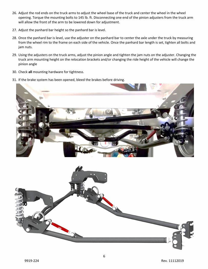
26. Adjust the rod ends on the truck arms to adjust the wheel base of the truck and center the wheel in the wheel opening. Torque the mounting bolts to 145 lb. ft. Disconnecting one end of the pinion adjusters from the truck arm will allow the front of the arm to be lowered down for adjustment.
27. Adjust the panhard bar height so the panhard bar is level.
28. Once the panhard bar is level, use the adjuster on the panhard bar to center the axle under the truck by measuring from the wheel rim to the frame on each side of the vehicle. Once the panhard bar length is set, tighten all bolts and jam nuts.
29. Using the adjusters on the truck arms, adjust the pinion angle and tighten the jam nuts on the adjuster. Changing the truck arm mounting height on the relocation brackets and/or changing the ride height of the vehicle will change the pinion angle
30. Check all mounting hardware for tightness.
31. If the brake system has been opened, bleed the brakes before driving.
7 9919-224 Rev. 11112019
8 9919-224 Rev. 11112019
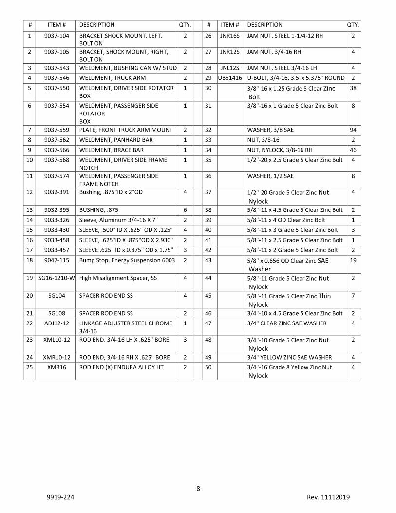
# ITEM # DESCRIPTION QTY.
# ITEM # DESCRIPTION QTY.
1 9037-104 BRACKET,SHOCK MOUNT, LEFT, BOLT ON
2
26 JNR16S JAM NUT, STEEL 1-1/4-12 RH 2
2 9037-105 BRACKET, SHOCK MOUNT, RIGHT, BOLT ON
2
27 JNR12S JAM NUT, 3/4-16 RH 4
3 9037-543 WELDMENT, BUSHING CAN W/ STUD 2
28 JNL12S JAM NUT, STEEL 3/4-16 LH 4
4 9037-546 WELDMENT, TRUCK ARM 2
29 UB51416 U-BOLT, 3/4-16, 3.5"x 5.375" ROUND 2
5 9037-550 WELDMENT, DRIVER SIDE ROTATOR BOX
1
30
3/8"-16 x 1.25 Grade 5 Clear Zinc Bolt
38
6 9037-554 WELDMENT, PASSENGER SIDE ROTATOR BOX
1
31
3/8"-16 x 1 Grade 5 Clear Zinc Bolt 8
7 9037-559 PLATE, FRONT TRUCK ARM MOUNT 2
32
WASHER, 3/8 SAE 94
8 9037-562 WELDMENT, PANHARD BAR 1
33
NUT, 3/8-16 2
9 9037-566 WELDMENT, BRACE BAR 1
34
NUT, NYLOCK, 3/8-16 RH 46
10 9037-568 WELDMENT, DRIVER SIDE FRAME NOTCH
1
35
1/2"-20 x 2.5 Grade 5 Clear Zinc Bolt 4
11 9037-574 WELDMENT, PASSENGER SIDE FRAME NOTCH
1
36
WASHER, 1/2 SAE 8
12 9032-391 Bushing, .875"ID x 2"OD 4
37
1/2"-20 Grade 5 Clear Zinc Nut Nylock
4
13 9032-395 BUSHING, .875 6
38
5/8"-11 x 4.5 Grade 5 Clear Zinc Bolt 2
14 9033-326 Sleeve, Aluminum 3/4-16 X 7" 2
39
5/8"-11 x 4 OD Clear Zinc Bolt 1
15 9033-430 SLEEVE, .500" ID X .625" OD X .125" 4
40
5/8"-11 x 3 Grade 5 Clear Zinc Bolt 3
16 9033-458 SLEEVE, .625"ID X .875"OD X 2.930" 2
41
5/8"-11 x 2.5 Grade 5 Clear Zinc Bolt 1
17 9033-457 SLEEVE .625" ID x 0.875" OD x 1.75" 3
42
5/8"-11 x 2 Grade 5 Clear Zinc Bolt 2
18 9047-115 Bump Stop, Energy Suspension 6003 2
43
5/8" x 0.656 OD Clear Zinc SAE Washer
19
19 SG16-1210-W High Misalignment Spacer, SS 4
44
5/8"-11 Grade 5 Clear Zinc Nut Nylock
2
20 SG104 SPACER ROD END SS 4
45
5/8"-11 Grade 5 Clear Zinc Thin Nylock
7
21 SG108 SPACER ROD END SS 2
46
3/4"-10 x 4.5 Grade 5 Clear Zinc Bolt 2
22 ADJ12-12 LINKAGE ADJUSTER STEEL CHROME 3/4-16
1
47
3/4" CLEAR ZINC SAE WASHER 4
23 XML10-12 ROD END, 3/4-16 LH X .625" BORE 3
48
3/4"-10 Grade 5 Clear Zinc Nut Nylock
2
24 XMR10-12 ROD END, 3/4-16 RH X .625" BORE 2
49
3/4" YELLOW ZINC SAE WASHER 4
25 XMR16 ROD END (X) ENDURA ALLOY HT 2
50
3/4"-16 Grade 8 Yellow Zinc Nut
Nylock 4