Embed Size (px)
Citation preview
TECHNICAL TEACHING EQUIPMENT
ENGINEERING LABORATORY CATALOGUE OC
T 2020
-
Logo-DK
A - FLUID MECHANICS FOUNDATIONS
B - HYDRAULIC MACHINES
C - HYDRAULICS, HYDROLOGY AND WATER
TREATMENT
D - AERODYNAMICS
E - RENEWABLE ENERGY
F - THERMODYNAMICS
I - CHEMISTRY
K - MECHANICS
N - MAINTENANCE
Catalogos-Pie19DIKOIN Ingeniería S.L.+034 946 55 15 35 / www.dikoin.com / [email protected] reserves the right to make changes in technical and product specifications without prior notice.
A - FLUID MECHANICS FOUNDATIONS
Logo-DK
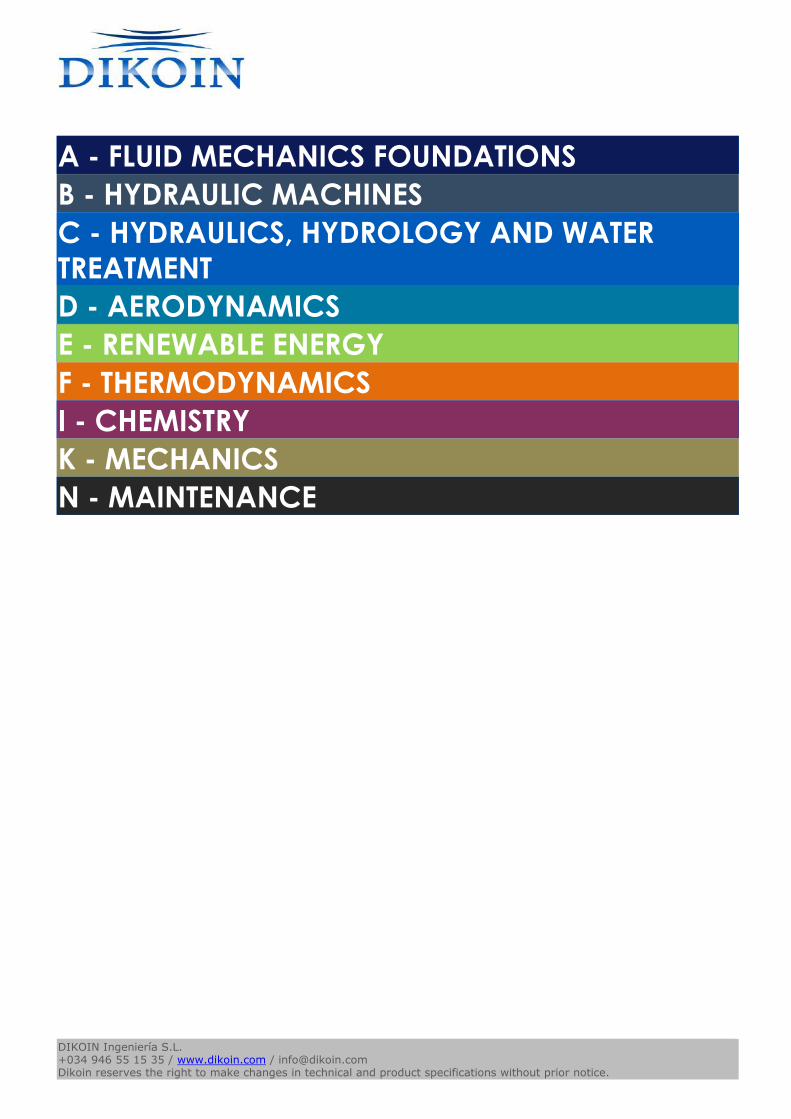
FL 01.1 - HYDRAULIC UNIT (pag. A - 1) FL 01.2 - FLOW BY WEIRS (pag. A - 1) FL 01.3 - HYDROSTATIC BENCH (pag. A - 1)
FL 01.4 - HYDRAULIC BENCH (pag. A - 2) FL 01.6 - HYDRAULIC BASIC BENCH (pag. A - 2) FL 01.7 - HIGH FLOW HYDRAULIC BENCH (pag. A - 2)
FL 02.1 - LOSSES IN PIPES PANEL (pag. A - 3) FL 04.1 - PIPELINE NETWORKS (pag. A - 3) FL 06.1 - VENTURI, BERNOULLI AND CAVITATION EFFECTS
(pag. A - 3)
FL 06.2 - BERNOULLI (pag. A - 4) FL 06.3 - CAVITATION STUDY (pag. A - 4) FL 09.2 - HYDRAULIC RAM (pag. A - 4)
FL 10.1 - HYDROSTATIC PRESSURE ON SUBMERGED
SURFACES (pag. A - 5)
FL 10.2 - METACENTRIC HEIGHT (pag. A - 5) FL 11.1 - WATER JET FORCES (pag. A - 5)
Catalogos-Pie19DIKOIN Ingeniería S.L.+034 946 55 15 35 / www.dikoin.com / [email protected] reserves the right to make changes in technical and product specifications without prior notice.
A - FLUID MECHANICS FOUNDATIONS
Logo-DK
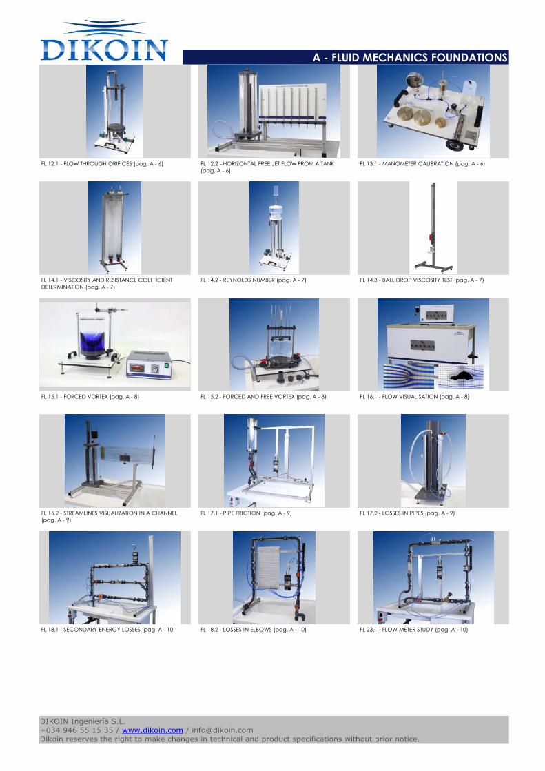
FL 12.1 - FLOW THROUGH ORIFICES (pag. A - 6) FL 12.2 - HORIZONTAL FREE JET FLOW FROM A TANK
(pag. A - 6)
FL 13.1 - MANOMETER CALIBRATION (pag. A - 6)
FL 14.1 - VISCOSITY AND RESISTANCE COEFFICIENT
DETERMINATION (pag. A - 7)
FL 14.2 - REYNOLDS NUMBER (pag. A - 7) FL 14.3 - BALL DROP VISCOSITY TEST (pag. A - 7)
FL 15.1 - FORCED VORTEX (pag. A - 8) FL 15.2 - FORCED AND FREE VORTEX (pag. A - 8) FL 16.1 - FLOW VISUALISATION (pag. A - 8)
FL 16.2 - STREAMLINES VISUALIZATION IN A CHANNEL
(pag. A - 9)
FL 17.1 - PIPE FRICTION (pag. A - 9) FL 17.2 - LOSSES IN PIPES (pag. A - 9)
FL 18.1 - SECONDARY ENERGY LOSSES (pag. A - 10) FL 18.2 - LOSSES IN ELBOWS (pag. A - 10) FL 23.1 - FLOW METER STUDY (pag. A - 10)
Catalogos-Pie19DIKOIN Ingeniería S.L.+034 946 55 15 35 / www.dikoin.com / [email protected] reserves the right to make changes in technical and product specifications without prior notice.
A - FLUID MECHANICS FOUNDATIONS
Logo-DK
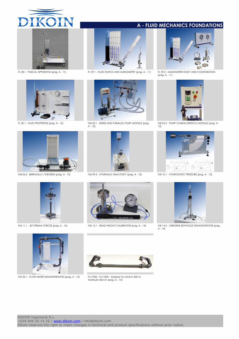
FL 28.1 - PASCAL APPARATUS (pag. A - 11) FL 29.1 - FLUID STATICS AND MANOMETRY (pag. A - 11) FL 29.3 - MANOMETER STUDY AND COMPARATION
(pag. A - 11)
FL 30.1 - FLUID PROPERTIES (pag. A - 12) FLB 03.1 - SERIES AND PARALLEL PUMP MODULE (pag.
A - 12)
FLB 03.2 - PUMP CHARACTERISTICS MODULE (pag. A -
12)
FLB 06.2 - BERNOULLI`s THEOREM (pag. A - 13) FLB 09.2 - HYDRAULIC RAM STUDY (pag. A - 13) FLB 10.1 - HYDROSTATIC PRESSURE (pag. A - 13)
FLB 11.1 - JET STREAM FORCES (pag. A - 14) FLB 13.1 - DEAD WEIGHT CALIBRATOR (pag. A - 14) FLB 14.2 - OSBORNE REYNOLDS DEMONSTRATOR (pag.
A - 14)
FLB 23.1 - FLOW METER DEMONSTRATION (pag. A - 15) FLZ.T500 - FLZ.T500 - Adapter for stretch 500 to
Hydraulic Bench (pag. A - 15)
Catalogos-Pie19DIKOIN Ingeniería S.L.+034 946 55 15 35 / www.dikoin.com / [email protected] reserves the right to make changes in technical and product specifications without prior notice.
Logo-DK
A - FLUID MECHANICS FOUNDATIONS
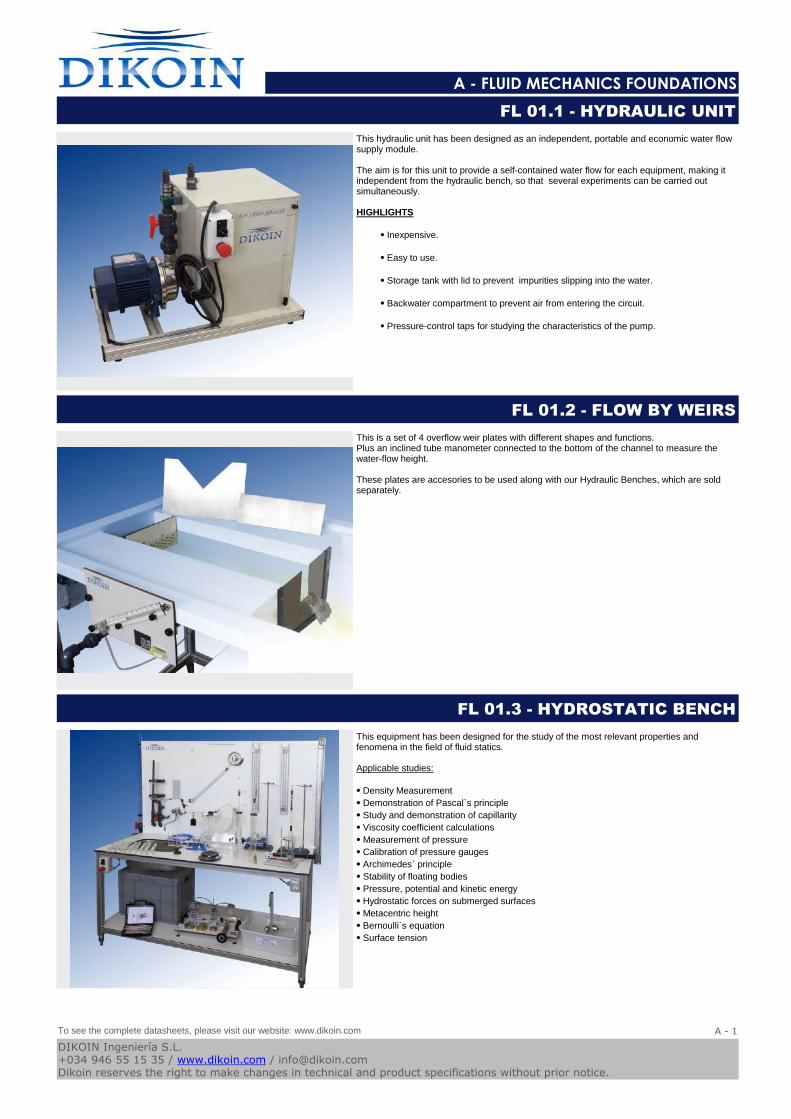
This hydraulic unit has been designed as an independent, portable and economic water flow supply module.
The aim is for this unit to provide a self-contained water flow for each equipment, making it independent from the hydraulic bench, so that several experiments can be carried out simultaneously.
HIGHLIGHTS
⦁ Inexpensive.
⦁ Easy to use.
⦁ Storage tank with lid to prevent impurities slipping into the water.
⦁ Backwater compartment to prevent air from entering the circuit.
⦁ Pressure-control taps for studying the characteristics of the pump.
FL 01.1 - HYDRAULIC UNIT
This is a set of 4 overflow weir plates with different shapes and functions.Plus an inclined tube manometer connected to the bottom of the channel to measure the water-flow height.
These plates are accesories to be used along with our Hydraulic Benches, which are sold separately.
FL 01.2 - FLOW BY WEIRS
This equipment has been designed for the study of the most relevant properties and fenomena in the field of fluid statics.
Applicable studies:
⦁ Density Measurement
⦁ Demonstration of Pascal`s principle
⦁ Study and demonstration of capillarity
⦁ Viscosity coefficient calculations
⦁ Measurement of pressure
⦁ Calibration of pressure gauges
⦁ Archimedes` principle
⦁ Stability of floating bodies
⦁ Pressure, potential and kinetic energy
⦁ Hydrostatic forces on submerged surfaces
⦁ Metacentric height
⦁ Bernoulli`s equation
⦁ Surface tension
FL 01.3 - HYDROSTATIC BENCH
To see the complete datasheets, please visit our website: www.dikoin.com
Catalogos-Pie19A - 1
DIKOIN Ingeniería S.L.+034 946 55 15 35 / www.dikoin.com / [email protected] reserves the right to make changes in technical and product specifications without prior notice.
Logo-DK
A - FLUID MECHANICS FOUNDATIONS
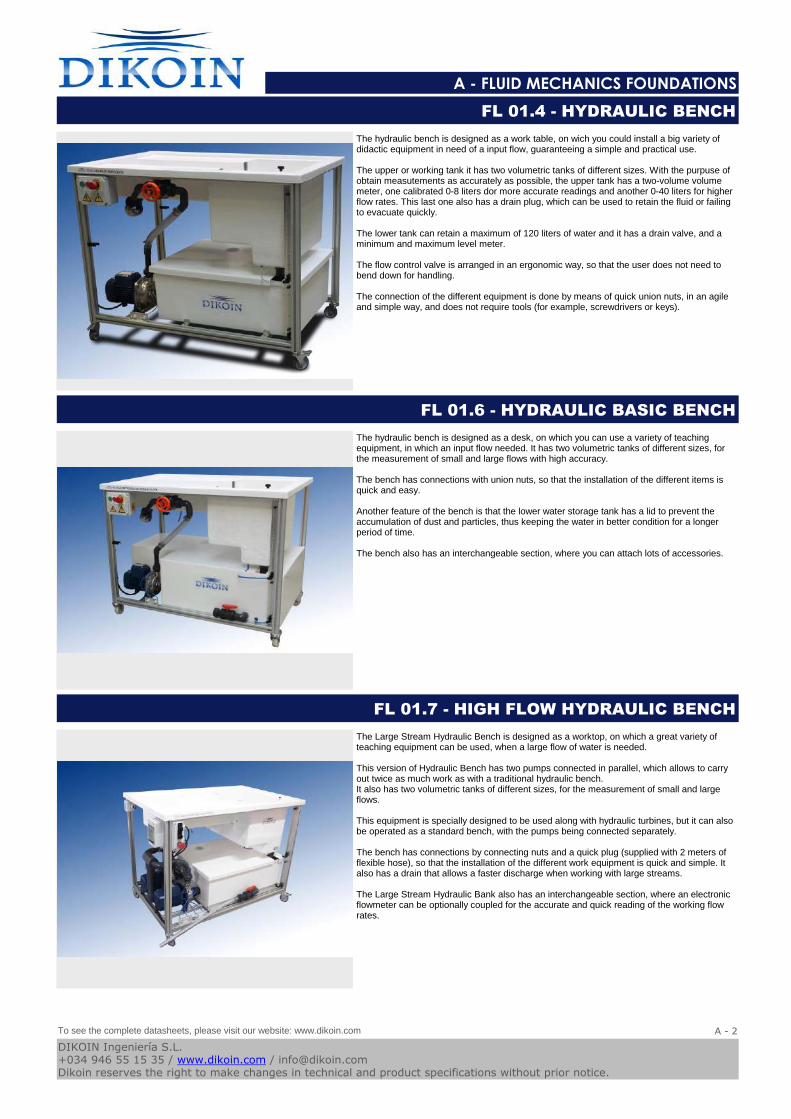
The hydraulic bench is designed as a work table, on wich you could install a big variety of didactic equipment in need of a input flow, guaranteeing a simple and practical use.
The upper or working tank it has two volumetric tanks of different sizes. With the purpuse of obtain measutements as accurately as possible, the upper tank has a two-volume volume meter, one calibrated 0-8 liters dor more accurate readings and another 0-40 liters for higher flow rates. This last one also has a drain plug, which can be used to retain the fluid or failing to evacuate quickly.
The lower tank can retain a maximum of 120 liters of water and it has a drain valve, and a minimum and maximum level meter.
The flow control valve is arranged in an ergonomic way, so that the user does not need to bend down for handling.
The connection of the different equipment is done by means of quick union nuts, in an agile and simple way, and does not require tools (for example, screwdrivers or keys).
FL 01.4 - HYDRAULIC BENCH
The hydraulic bench is designed as a desk, on which you can use a variety of teaching equipment, in which an input flow needed. It has two volumetric tanks of different sizes, for the measurement of small and large flows with high accuracy.
The bench has connections with union nuts, so that the installation of the different items is quick and easy.
Another feature of the bench is that the lower water storage tank has a lid to prevent the accumulation of dust and particles, thus keeping the water in better condition for a longer period of time.
The bench also has an interchangeable section, where you can attach lots of accessories.
FL 01.6 - HYDRAULIC BASIC BENCH
The Large Stream Hydraulic Bench is designed as a worktop, on which a great variety of teaching equipment can be used, when a large flow of water is needed.
This version of Hydraulic Bench has two pumps connected in parallel, which allows to carry out twice as much work as with a traditional hydraulic bench.It also has two volumetric tanks of different sizes, for the measurement of small and large flows.
This equipment is specially designed to be used along with hydraulic turbines, but it can also be operated as a standard bench, with the pumps being connected separately.
The bench has connections by connecting nuts and a quick plug (supplied with 2 meters of flexible hose), so that the installation of the different work equipment is quick and simple. It also has a drain that allows a faster discharge when working with large streams.
The Large Stream Hydraulic Bank also has an interchangeable section, where an electronic flowmeter can be optionally coupled for the accurate and quick reading of the working flow rates.
FL 01.7 - HIGH FLOW HYDRAULIC BENCH
To see the complete datasheets, please visit our website: www.dikoin.com
Catalogos-Pie19A - 2
DIKOIN Ingeniería S.L.+034 946 55 15 35 / www.dikoin.com / [email protected] reserves the right to make changes in technical and product specifications without prior notice.
Logo-DK
A - FLUID MECHANICS FOUNDATIONS
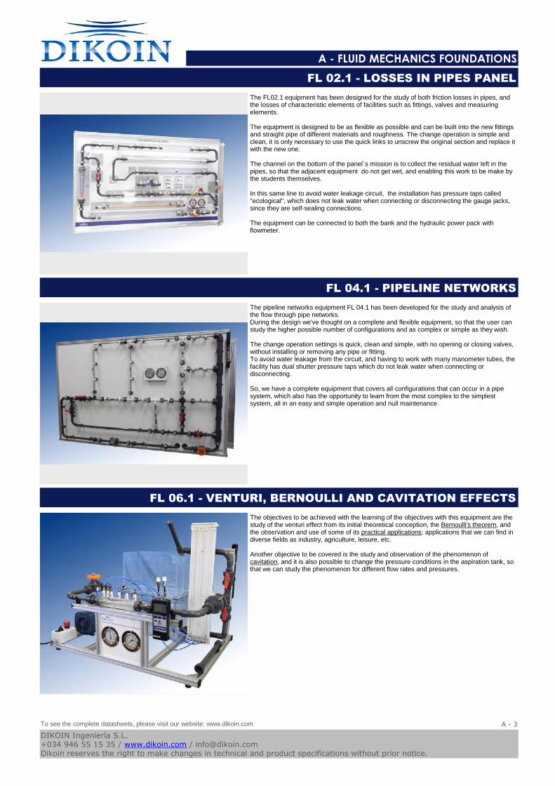
The FL02.1 equipment has been designed for the study of both friction losses in pipes, and the losses of characteristic elements of facilities such as fittings, valves and measuring elements.
The equipment is designed to be as flexible as possible and can be built into the new fittings and straight pipe of different materials and roughness. The change operation is simple and clean, it is only necessary to use the quick links to unscrew the original section and replace it with the new one.
The channel on the bottom of the panel`s mission is to collect the residual water left in the pipes, so that the adjacent equipment do not get wet, and enabling this work to be make by the students themselves.
In this same line to avoid water leakage circuit, the installation has pressure taps called "ecological", which does not leak water when connecting or disconnecting the gauge jacks, since they are self-sealing connections.
The equipment can be connected to both the bank and the hydraulic power pack with flowmeter.
FL 02.1 - LOSSES IN PIPES PANEL
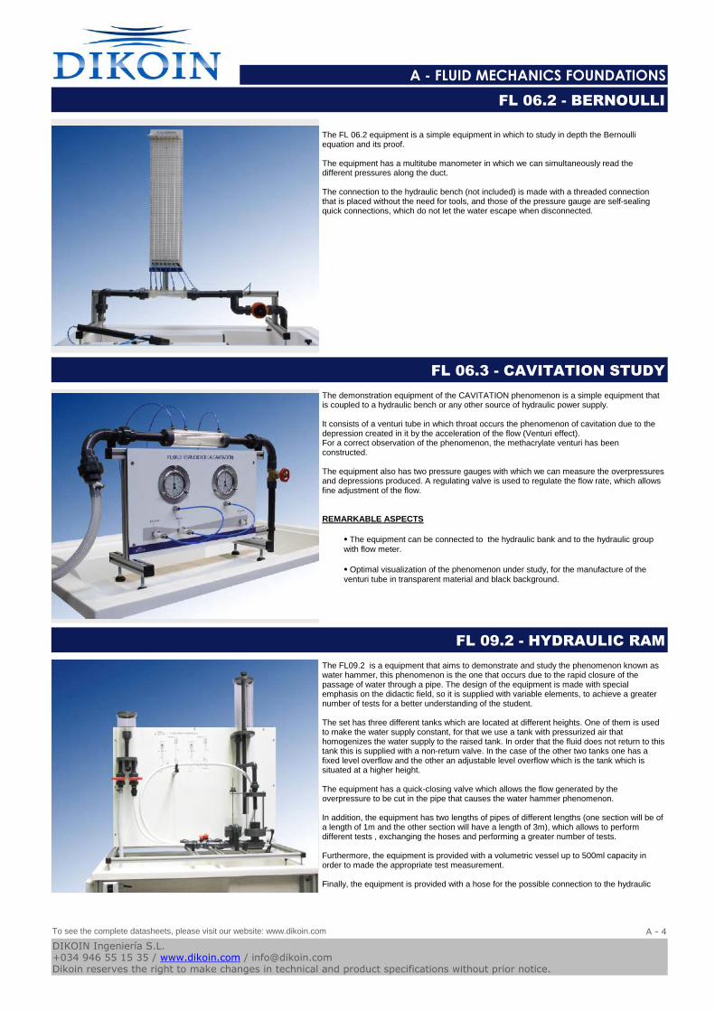
The pipeline networks equipment FL 04.1 has been developed for the study and analysis of the flow through pipe networks.During the design we've thought on a complete and flexible equipment, so that the user can study the higher possible number of configurations and as complex or simple as they wish.
The change operation settings is quick, clean and simple, with no opening or closing valves, without installing or removing any pipe or fitting.To avoid water leakage from the circuit, and having to work with many manometer tubes, the facility has dual shutter pressure taps which do not leak water when connecting or disconnecting.
So, we have a complete equipment that covers all configurations that can occur in a pipe system, which also has the opportunity to learn from the most complex to the simplest system, all in an easy and simple operation and null maintenance.
FL 04.1 - PIPELINE NETWORKS
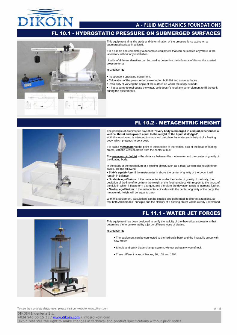
The objectives to be achieved with the learning of the objectives with this equipment are the study of the venturi effect from its initial theoretical conception, the Bernoulli's theorem, and the observation and use of some of its practical applications; applications that we can find in diverse fields as industry, agriculture, leisure, etc.
Another objective to be covered is the study and observation of the phenomenon of cavitation, and it is also possible to change the pressure conditions in the aspiration tank, so that we can study the phenomenon for different flow rates and pressures.
FL 06.1 - VENTURI, BERNOULLI AND CAVITATION EFFECTS
To see the complete datasheets, please visit our website: www.dikoin.com
Catalogos-Pie19A - 3
DIKOIN Ingeniería S.L.+034 946 55 15 35 / www.dikoin.com / [email protected] reserves the right to make changes in technical and product specifications without prior notice.
Logo-DK
A - FLUID MECHANICS FOUNDATIONS
The FL 06.2 equipment is a simple equipment in which to study in depth the Bernoulli equation and its proof.
The equipment has a multitube manometer in which we can simultaneously read the different pressures along the duct.
The connection to the hydraulic bench (not included) is made with a threaded connection that is placed without the need for tools, and those of the pressure gauge are self-sealing quick connections, which do not let the water escape when disconnected.
FL 06.2 - BERNOULLI
The demonstration equipment of the CAVITATION phenomenon is a simple equipment that is coupled to a hydraulic bench or any other source of hydraulic power supply.
It consists of a venturi tube in which throat occurs the phenomenon of cavitation due to the depression created in it by the acceleration of the flow (Venturi effect). For a correct observation of the phenomenon, the methacrylate venturi has been constructed.
The equipment also has two pressure gauges with which we can measure the overpressures and depressions produced. A regulating valve is used to regulate the flow rate, which allows fine adjustment of the flow.
REMARKABLE ASPECTS
⦁ The equipment can be connected to the hydraulic bank and to the hydraulic group with flow meter.
⦁ Optimal visualization of the phenomenon under study, for the manufacture of the venturi tube in transparent material and black background.
FL 06.3 - CAVITATION STUDY
The FL09.2 is a equipment that aims to demonstrate and study the phenomenon known as water hammer, this phenomenon is the one that occurs due to the rapid closure of the passage of water through a pipe. The design of the equipment is made with special emphasis on the didactic field, so it is supplied with variable elements, to achieve a greater number of tests for a better understanding of the student.
The set has three different tanks which are located at different heights. One of them is used to make the water supply constant, for that we use a tank with pressurized air that homogenizes the water supply to the raised tank. In order that the fluid does not return to this tank this is supplied with a non-return valve. In the case of the other two tanks one has a fixed level overflow and the other an adjustable level overflow which is the tank which is situated at a higher height.
The equipment has a quick-closing valve which allows the flow generated by the overpressure to be cut in the pipe that causes the water hammer phenomenon.
In addition, the equipment has two lengths of pipes of different lengths (one section will be of a length of 1m and the other section will have a length of 3m), which allows to perform different tests , exchanging the hoses and performing a greater number of tests.
Furthermore, the equipment is provided with a volumetric vessel up to 500ml capacity in order to made the appropriate test measurement.
Finally, the equipment is provided with a hose for the possible connection to the hydraulic
FL 09.2 - HYDRAULIC RAM
To see the complete datasheets, please visit our website: www.dikoin.com
Catalogos-Pie19A - 4
DIKOIN Ingeniería S.L.+034 946 55 15 35 / www.dikoin.com / [email protected] reserves the right to make changes in technical and product specifications without prior notice.
Logo-DK
A - FLUID MECHANICS FOUNDATIONS
This equipment aims the study and determination of the pressure force acting on a submerged surface in a liquid.
It is a simple and completely autonomous equipment that can be located anywhere in the laboratory without any installation.
Liquids of different densities can be used to determine the influence of this on the exerted pressure force.
HIGHLIGHTS
⦁ Independent operating equipment.
⦁ Calculation of the pressure force exerted on both flat and curve surfaces.
⦁ Possibility of varying the angle of the surface on which the study is made.
⦁ It has a pump to recirculate the water, so it doesn`t need any jar or element to fill the tank during the experiments.
FL 10.1 - HYDROSTATIC PRESSURE ON SUBMERGED SURFACES
The principle of Archimedes says that: "Every body submerged in a liquid experiences a vertical thrust and upward equal to the weight of the liquid dislodged". With this equipment is intended to study and calculate the metacentric height of a floating body, which pretends to be a boat.
It is called metacenter to the point of intersection of the vertical axis of the boat or floating object, with the vertical drawn from the center of hull.
The metacentric height is the distance between the metacenter and the center of gravity of the floating body.
In the study of the equilibrium of a floating object, such as a boat, we can distinguish three cases, are the following:
⦁ Stable equilibrium: If the metacenter is above the center of gravity of the body, it will remain in balance.
⦁ Unstable equilibrium: If the metacenter is under the center of gravity of the body, the deviation of the line of force from the weight of the floating object with respect to the thrust of the fluid in which it floats form a torque, and therefore the deviation tends to increase further.
⦁ Neutral equilibrium: If the metacenter coincides with the center of gravity of the body, the metacentric height will be equal to zero.
With this equipment, calculations can be studied and performed in different situations, so that both Archimedes` principle and the stability of a floating object will be clearly understood.
FL 10.2 - METACENTRIC HEIGHT
This equipment has been designed to verify the validity of the theoretical expressions that determine the force exerted by a jet on different types of blades.
HIGHLIGHTS
⦁ The equipment can be connected to the hydraulic bank and the hydraulic group with flow meter.
⦁ Simple and quick blade change system, without using any type of tool.
⦁ Three different types of blades, 90, 105 and 180º.
FL 11.1 - WATER JET FORCES
To see the complete datasheets, please visit our website: www.dikoin.com
Catalogos-Pie19A - 5
DIKOIN Ingeniería S.L.+034 946 55 15 35 / www.dikoin.com / [email protected] reserves the right to make changes in technical and product specifications without prior notice.
Logo-DK
A - FLUID MECHANICS FOUNDATIONS
The FL12.1 equipment has been designed for the study of the contraction that occurs when a jet of fluid passes through an orifice. Its design is aimed at making teaching and learning easy thanks to its three differently-shaped nozzles. This enables a variety of conditions to carry out the tests.
The unit is equipped with a Pitot tube to measure the velocity of the fluid being discharged through the outlet.
In addition, the equipment has a measuring instrument of the jet diameter, which can be regulated, obtaining results of a greater accuracy.
Finally, this apparatus includes a water column manometer for the measurement of both the water level in the tank and the velocity of the water jet.
HIGHLIGHTS:
The equipment must be connected to the hydraulic bench.
FL 12.1 - FLOW THROUGH ORIFICES
This equipment, has been designed for the study of all concerning the outlet of flow through orifices.
The water tank has adjustable height, reason why flow tests can be made in different conditions of pressure. The deposit has a scale that indicates the height of the level of liquid at every moment.
The equipment includes a panel with 8 indicating gauges, easily adjustable to the trajectory of the jet paths, and very simple to take the data.
The different nozzles are adjusted to the inner surface of the tank, obtaining the minimum possible disturbances.
On the other hand, the equipment has a built-in bubble level that allows us to know if the equipment has been correctly leveled, as well as vertically adjustable feet, to easily level the equipment.
The construction of the equipment in materials as aluminum or stainless steel, in all its metallic parts, guarantees the durability of it.
FL 12.2 - HORIZONTAL FREE JET FLOW FROM A TANK
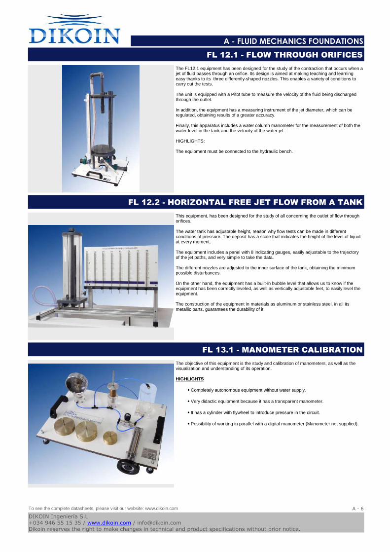
The objective of this equipment is the study and calibration of manometers, as well as the visualization and understanding of its operation.
HIGHLIGHTS
⦁ Completely autonomous equipment without water supply.
⦁ Very didactic equipment because it has a transparent manometer.
⦁ It has a cylinder with flywheel to introduce pressure in the circuit.
⦁ Possibility of working in parallel with a digital manometer (Manometer not supplied).
FL 13.1 - MANOMETER CALIBRATION
To see the complete datasheets, please visit our website: www.dikoin.com
Catalogos-Pie19A - 6
DIKOIN Ingeniería S.L.+034 946 55 15 35 / www.dikoin.com / [email protected] reserves the right to make changes in technical and product specifications without prior notice.
Logo-DK
A - FLUID MECHANICS FOUNDATIONS
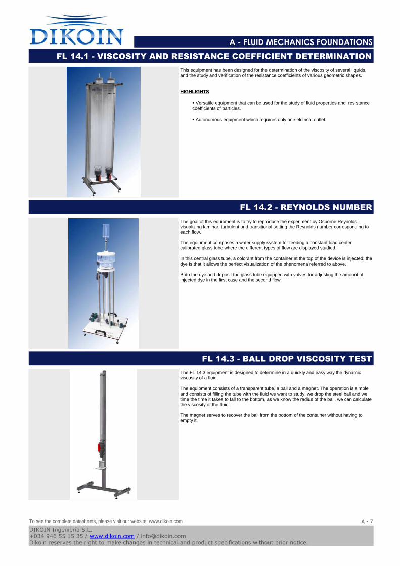
This equipment has been designed for the determination of the viscosity of several liquids, and the study and verification of the resistance coefficients of various geometric shapes.
HIGHLIGHTS
⦁ Versatile equipment that can be used for the study of fluid properties and resistance coefficients of particles.
⦁ Autonomous equipment which requires only one elctrical outlet.
FL 14.1 - VISCOSITY AND RESISTANCE COEFFICIENT DETERMINATION
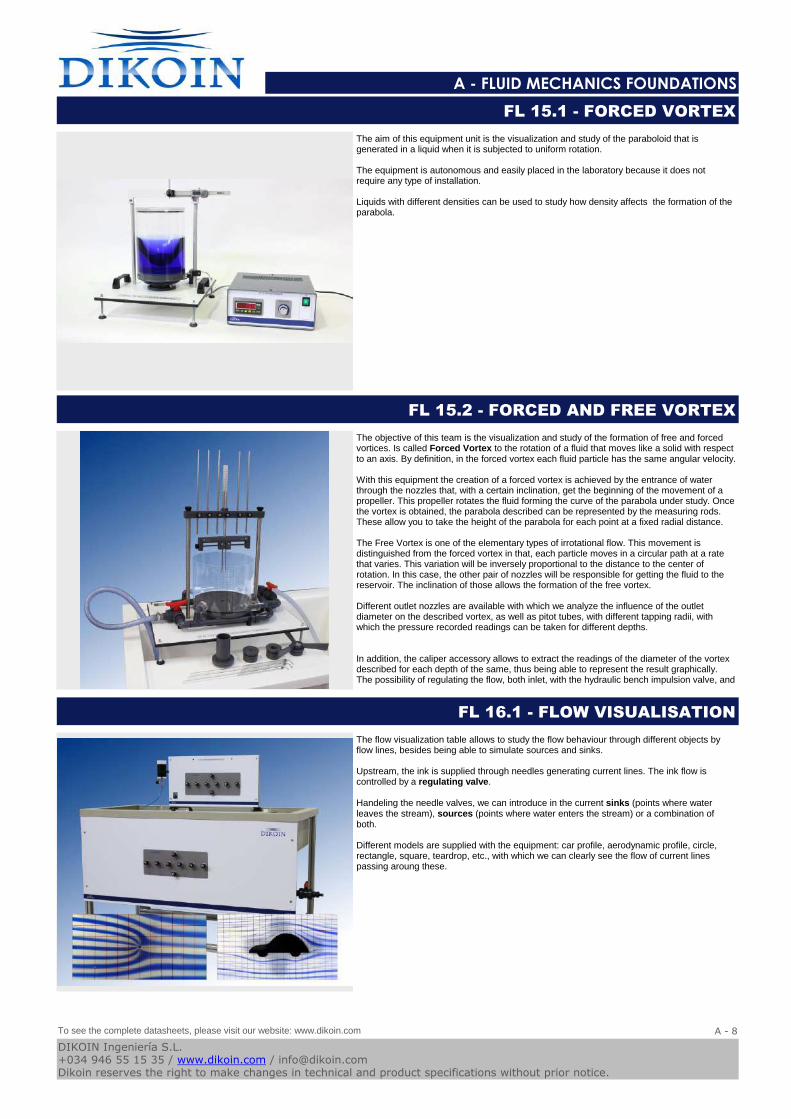
The goal of this equipment is to try to reproduce the experiment by Osborne Reynolds visualizing laminar, turbulent and transitional setting the Reynolds number corresponding to each flow.
The equipment comprises a water supply system for feeding a constant load center calibrated glass tube where the different types of flow are displayed studied.
In this central glass tube, a colorant from the container at the top of the device is injected, the dye is that it allows the perfect visualization of the phenomena referred to above.
Both the dye and deposit the glass tube equipped with valves for adjusting the amount of injected dye in the first case and the second flow.
FL 14.2 - REYNOLDS NUMBER
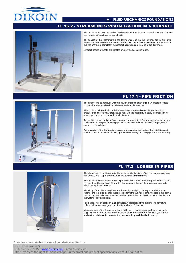
The FL 14.3 equipment is designed to determine in a quickly and easy way the dynamic viscosity of a fluid.
The equipment consists of a transparent tube, a ball and a magnet. The operation is simple and consists of filling the tube with the fluid we want to study, we drop the steel ball and we time the time it takes to fall to the bottom, as we know the radius of the ball, we can calculate the viscosity of the fluid.
The magnet serves to recover the ball from the bottom of the container without having to empty it.
FL 14.3 - BALL DROP VISCOSITY TEST
To see the complete datasheets, please visit our website: www.dikoin.com
Catalogos-Pie19A - 7
DIKOIN Ingeniería S.L.+034 946 55 15 35 / www.dikoin.com / [email protected] reserves the right to make changes in technical and product specifications without prior notice.
Logo-DK
A - FLUID MECHANICS FOUNDATIONS
The aim of this equipment unit is the visualization and study of the paraboloid that is generated in a liquid when it is subjected to uniform rotation.
The equipment is autonomous and easily placed in the laboratory because it does not require any type of installation.
Liquids with different densities can be used to study how density affects the formation of the parabola.
FL 15.1 - FORCED VORTEX
The objective of this team is the visualization and study of the formation of free and forced vortices. Is called Forced Vortex to the rotation of a fluid that moves like a solid with respect to an axis. By definition, in the forced vortex each fluid particle has the same angular velocity.
With this equipment the creation of a forced vortex is achieved by the entrance of water through the nozzles that, with a certain inclination, get the beginning of the movement of a propeller. This propeller rotates the fluid forming the curve of the parabola under study. Once the vortex is obtained, the parabola described can be represented by the measuring rods. These allow you to take the height of the parabola for each point at a fixed radial distance.
The Free Vortex is one of the elementary types of irrotational flow. This movement is distinguished from the forced vortex in that, each particle moves in a circular path at a rate that varies. This variation will be inversely proportional to the distance to the center of rotation. In this case, the other pair of nozzles will be responsible for getting the fluid to the reservoir. The inclination of those allows the formation of the free vortex.
Different outlet nozzles are available with which we analyze the influence of the outlet diameter on the described vortex, as well as pitot tubes, with different tapping radii, with which the pressure recorded readings can be taken for different depths.
In addition, the caliper accessory allows to extract the readings of the diameter of the vortex described for each depth of the same, thus being able to represent the result graphically.The possibility of regulating the flow, both inlet, with the hydraulic bench impulsion valve, and
FL 15.2 - FORCED AND FREE VORTEX
The flow visualization table allows to study the flow behaviour through different objects by flow lines, besides being able to simulate sources and sinks.
Upstream, the ink is supplied through needles generating current lines. The ink flow is controlled by a regulating valve.
Handeling the needle valves, we can introduce in the current sinks (points where water leaves the stream), sources (points where water enters the stream) or a combination of both.
Different models are supplied with the equipment: car profile, aerodynamic profile, circle, rectangle, square, teardrop, etc., with which we can clearly see the flow of current lines passing aroung these.
FL 16.1 - FLOW VISUALISATION
To see the complete datasheets, please visit our website: www.dikoin.com
Catalogos-Pie19A - 8
DIKOIN Ingeniería S.L.+034 946 55 15 35 / www.dikoin.com / [email protected] reserves the right to make changes in technical and product specifications without prior notice.
Logo-DK
A - FLUID MECHANICS FOUNDATIONS
This equipment allows the study of the behavior of fluids in open channels and flow lines that form around different submerged objects.
The service for the experiments is the flowing water. So that the flow lines are visible during the experiments, diluted ink is used in water. This combination of elements with the feature that the channel is completely transparent allows optimal viewing of the flow lines .
Different bodies of landfill and profiles are provided as varied forms.
FL 16.2 - STREAMLINES VISUALIZATION IN A CHANNEL
The objective to be achieved with this equipment is the study of primary pressure losses produced along a pipeline in both laminar and turbulent regimen.
This equipment has a horizontal pipe in which perform readings of the pressure loss produced for different flow rates. It also has, with the possibility to study the friction in the same pipe for both laminar and turbulent regime.
To get this last, we feed pipe from a tank of constant height. For readings of upstream and downstream of the pressure test pipe, we have two differential pressure gauges, one of water and other digital.
For regulation of the flow use two valves, one located at the begin of the installation and another place at the exit of the test pipe. The flow through into the pipe is measured using .
FL 17.1 - PIPE FRICTION
The objective to be achieved with this equipment is the study of the primary losses of load that occur along a pipe, in two regimenes: laminar and turbulent.
This equipment counts on a vertical pipe, in which we make the readings of the loss of load produced for different flows; Flow rates that we obtain through the regulating valve with which the equipment counts.
The study of the different regimes is achieved by modifying the way in which the water reaches the test pipe, so that, in order to achieve the laminar regime, the pipe is fed from a tank of constant height while for the turbulent regime the supply will be made directly from the water supply equipment.
For the readings of upstream and downstream pressures of the test line, we have two differential pressure gauges, one of water and one of mercury.
Measurements of the flow rates obtained with the control valve are performed using the supplied test tube or the volumetric reservoir of the hydraulic bank (required), which also studies the relationship between the pressure drop and the fluid velocity.
FL 17.2 - LOSSES IN PIPES
To see the complete datasheets, please visit our website: www.dikoin.com
Catalogos-Pie19A - 9
DIKOIN Ingeniería S.L.+034 946 55 15 35 / www.dikoin.com / [email protected] reserves the right to make changes in technical and product specifications without prior notice.
Logo-DK
A - FLUID MECHANICS FOUNDATIONS
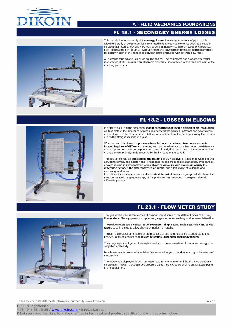
This installation for the study of the energy losses has straight sections of pipe, which allows the study of the primary loss generated in it. It also has elements such as elbows of different diameters at 90º and 45º, tees, widening, narrowing, different types of valves (ball, gate, diaphragm, non-return,...) with upstream and downstream pressure tappings arranged for determination of the head lodd between shots produced with different flow rates.
All pressure taps have quick plugs double sealed. The equipment has a water differential manometer of 1000 mm and an electronic differential manometer for the measurement of the resulting pressures.
FL 18.1 - SECONDARY ENERGY LOSSES
In order to calculate the secondary load losses produced by the fittings of an installation, we take data of the difference of pressures between the gauges upstream and downstream of the element to be measured, in addition, we must subtract the existing primary load losses due to the straight sections of a pipe.
When we want to obtain the pressure loss that occurs between two pressure ports located in pipes of different diameter, we must take into account that not all the difference of static pressures read corresponds to losses of load, that part is due to the transformation of static pressure in dynamic pressure by the increase of the speed.
The equipment has all possible configurations of 90 ° elbows, in addition to widening and abrupt narrowing, and a gate valve. These load losses are read simultaneously by means of a water column multimanometer, which allows to visualize with maximum clarity the difference between the different types of bends, and additionally, of widening and narrowing, and valve.In addition, the equipment has an electronic differential pressure gauge, which allows the measurement with a greater range, of the pressure loss produced in the gate valve with different openings.
FL 18.2 - LOSSES IN ELBOWS
The goal of this item is the study and comparison of some of the different types of existing flow meters. The equipment incorporates gauges for more teaching and representative flow.
These flowmeters are a Venturi tube, rotameter, diaphragm, angle seat valve and a Pitot tube placed in series to allow direct comparison of results.
Through the realization of some of the practices of this item has failed to understand the behavior of fluids against certain laws of statics, dynamics, thermodynamics.
They may implement general principles such as the conservation of mass, or energy in a simplified and easily.
Besides regulating valve with variable flow rates allow you to work according to the needs of the practice.
The results are displayed in both the water column manometer and the supplied electronic differential. Through these gauges pressure values are extracted at different strategic points of the equipment.
FL 23.1 - FLOW METER STUDY
To see the complete datasheets, please visit our website: www.dikoin.com
Catalogos-Pie19A - 10
DIKOIN Ingeniería S.L.+034 946 55 15 35 / www.dikoin.com / [email protected] reserves the right to make changes in technical and product specifications without prior notice.
Logo-DK
A - FLUID MECHANICS FOUNDATIONS
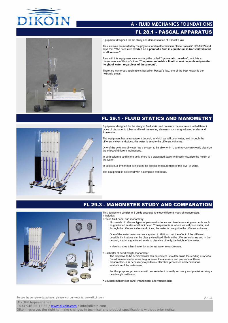
Equipment designed for the study and demonstration of Pascal`s law.
This law was enunciated by the physicist and mathematician Blaise Pascal (1623-1662) and says that "The pressure exerted on a point of a fluid in equilibrium is transmitted in full in all senses."
Also with this equipment we can study the called "hydrostatic paradox", which is a consequence of Pascal`s Law "The pressure inside a liquid at rest depends only on the height of water, regardless of the amount".
There are numerous applications based on Pascal`s law, one of the best known is the hydraulic press.
FL 28.1 - PASCAL APPARATUS
Equipment designed for the study of fluid static and pressure measurement with different types of piezometric tubes and level measuring elements such as graduated scales and limnimeter.
The equipment has a transparent deposit, in which we will pour water, and through the different valves and pipes, the water is sent to the different columns.
One of the columns of water has a system to be able to tilt it, so that you can clearly visualize the effect of different inclinations.
In both columns and in the tank, there is a graduated scale to directly visualize the height of the water.
In addition, a limnimeter is included for precise measurement of the level of water.
The equipment is delivered with a complete workbook.
FL 29.1 - FLUID STATICS AND MANOMETRY
This equipment consist in 3 unids arranged to study different types of manometers.It includes:
⦁ Static fluid panel and manometry.It consists of different types of piezometric tubes and level measuring elements such as graduated scales and limnimeter. Transparent tank where we will pour water, and through the different valves and pipes, the water is brought to the different columns.
One of the water columns has a system to tilt it, so that the effect of the different possible inclinations can be clearly visualized. Both in the different columns and in the deposit, it exist a graduated scale to visualice directly the height of the water.
It also includes a limnimeter for accurate water measurement.
⦁ Calibrator of dead-weight manometer.The objective to be achieved with this equipment is to determine the reading error of a Bourdon manometer since, to guarantee the accuracy and precision of these manometers, it is necessary to perform calibration processes and continuous evaluation of the instrument.
For this purpose, procedures will be carried out to verify accuracy and precision using a deadweight calibrator.
⦁ Bourdon manometer panel (manometer and vacuometer)
FL 29.3 - MANOMETER STUDY AND COMPARATION
To see the complete datasheets, please visit our website: www.dikoin.com
Catalogos-Pie19A - 11
DIKOIN Ingeniería S.L.+034 946 55 15 35 / www.dikoin.com / [email protected] reserves the right to make changes in technical and product specifications without prior notice.
Logo-DK
A - FLUID MECHANICS FOUNDATIONS
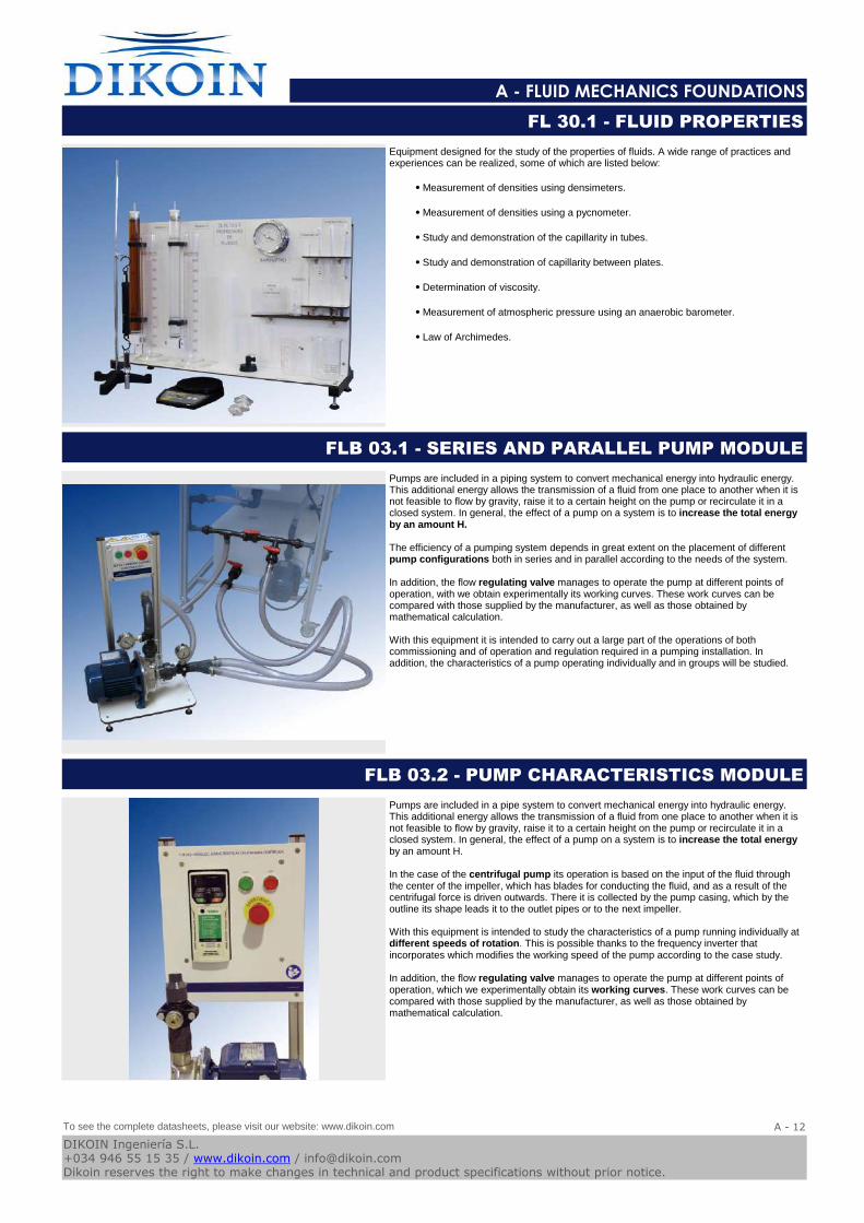
Equipment designed for the study of the properties of fluids. A wide range of practices and experiences can be realized, some of which are listed below:
⦁ Measurement of densities using densimeters.
⦁ Measurement of densities using a pycnometer.
⦁ Study and demonstration of the capillarity in tubes.
⦁ Study and demonstration of capillarity between plates.
⦁ Determination of viscosity.
⦁ Measurement of atmospheric pressure using an anaerobic barometer.
⦁ Law of Archimedes.
FL 30.1 - FLUID PROPERTIES
Pumps are included in a piping system to convert mechanical energy into hydraulic energy. This additional energy allows the transmission of a fluid from one place to another when it is not feasible to flow by gravity, raise it to a certain height on the pump or recirculate it in a closed system. In general, the effect of a pump on a system is to increase the total energy by an amount H.
The efficiency of a pumping system depends in great extent on the placement of different pump configurations both in series and in parallel according to the needs of the system.
In addition, the flow regulating valve manages to operate the pump at different points of operation, with we obtain experimentally its working curves. These work curves can be compared with those supplied by the manufacturer, as well as those obtained by mathematical calculation.
With this equipment it is intended to carry out a large part of the operations of both commissioning and of operation and regulation required in a pumping installation. In addition, the characteristics of a pump operating individually and in groups will be studied.
FLB 03.1 - SERIES AND PARALLEL PUMP MODULE
Pumps are included in a pipe system to convert mechanical energy into hydraulic energy. This additional energy allows the transmission of a fluid from one place to another when it is not feasible to flow by gravity, raise it to a certain height on the pump or recirculate it in a closed system. In general, the effect of a pump on a system is to increase the total energyby an amount H.
In the case of the centrifugal pump its operation is based on the input of the fluid through the center of the impeller, which has blades for conducting the fluid, and as a result of the centrifugal force is driven outwards. There it is collected by the pump casing, which by the outline its shape leads it to the outlet pipes or to the next impeller.
With this equipment is intended to study the characteristics of a pump running individually at different speeds of rotation. This is possible thanks to the frequency inverter that incorporates which modifies the working speed of the pump according to the case study.
In addition, the flow regulating valve manages to operate the pump at different points of operation, which we experimentally obtain its working curves. These work curves can be compared with those supplied by the manufacturer, as well as those obtained by mathematical calculation.
FLB 03.2 - PUMP CHARACTERISTICS MODULE
To see the complete datasheets, please visit our website: www.dikoin.com
Catalogos-Pie19A - 12
DIKOIN Ingeniería S.L.+034 946 55 15 35 / www.dikoin.com / [email protected] reserves the right to make changes in technical and product specifications without prior notice.
Logo-DK
A - FLUID MECHANICS FOUNDATIONS
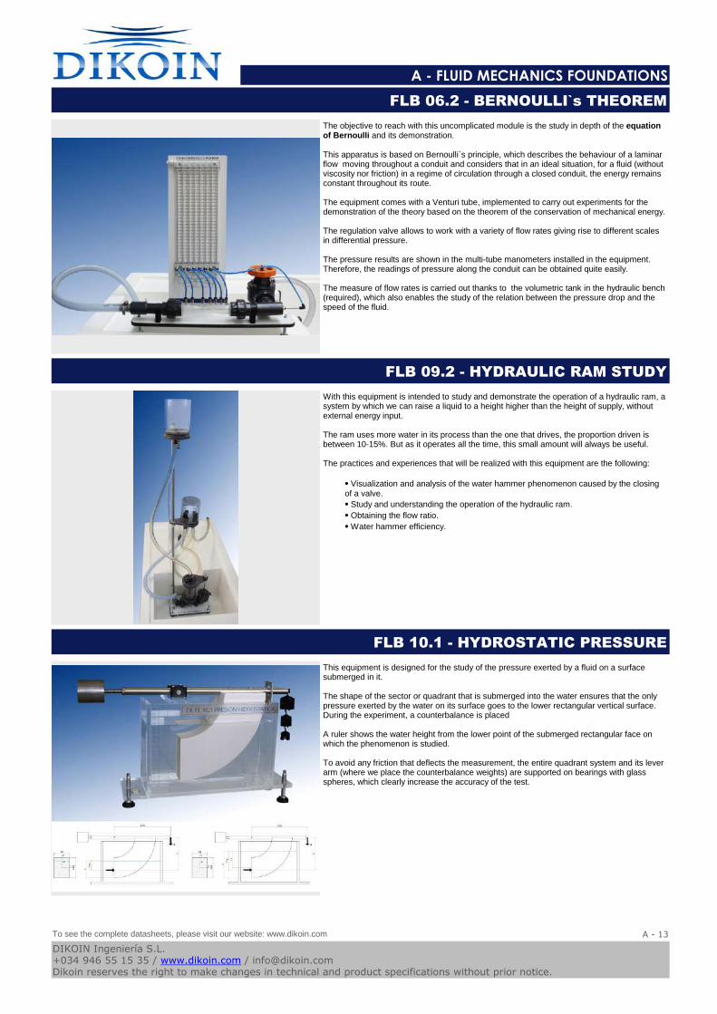
The objective to reach with this uncomplicated module is the study in depth of the equation of Bernoulli and its demonstration.
This apparatus is based on Bernoulli`s principle, which describes the behaviour of a laminar flow moving throughout a conduit and considers that in an ideal situation, for a fluid (without viscosity nor friction) in a regime of circulation through a closed conduit, the energy remains constant throughout its route.
The equipment comes with a Venturi tube, implemented to carry out experiments for the demonstration of the theory based on the theorem of the conservation of mechanical energy.
The regulation valve allows to work with a variety of flow rates giving rise to different scales in differential pressure.
The pressure results are shown in the multi-tube manometers installed in the equipment. Therefore, the readings of pressure along the conduit can be obtained quite easily.
The measure of flow rates is carried out thanks to the volumetric tank in the hydraulic bench (required), which also enables the study of the relation between the pressure drop and the speed of the fluid.
FLB 06.2 - BERNOULLI`s THEOREM
With this equipment is intended to study and demonstrate the operation of a hydraulic ram, a system by which we can raise a liquid to a height higher than the height of supply, without external energy input.
The ram uses more water in its process than the one that drives, the proportion driven is between 10-15%. But as it operates all the time, this small amount will always be useful.
The practices and experiences that will be realized with this equipment are the following:
⦁ Visualization and analysis of the water hammer phenomenon caused by the closing of a valve.
⦁ Study and understanding the operation of the hydraulic ram.
⦁ Obtaining the flow ratio.
⦁ Water hammer efficiency.
FLB 09.2 - HYDRAULIC RAM STUDY
This equipment is designed for the study of the pressure exerted by a fluid on a surface submerged in it.
The shape of the sector or quadrant that is submerged into the water ensures that the only pressure exerted by the water on its surface goes to the lower rectangular vertical surface. During the experiment, a counterbalance is placed
A ruler shows the water height from the lower point of the submerged rectangular face on which the phenomenon is studied.
To avoid any friction that deflects the measurement, the entire quadrant system and its lever arm (where we place the counterbalance weights) are supported on bearings with glass spheres, which clearly increase the accuracy of the test.
FLB 10.1 - HYDROSTATIC PRESSURE
To see the complete datasheets, please visit our website: www.dikoin.com
Catalogos-Pie19A - 13
DIKOIN Ingeniería S.L.+034 946 55 15 35 / www.dikoin.com / [email protected] reserves the right to make changes in technical and product specifications without prior notice.
Logo-DK
A - FLUID MECHANICS FOUNDATIONS
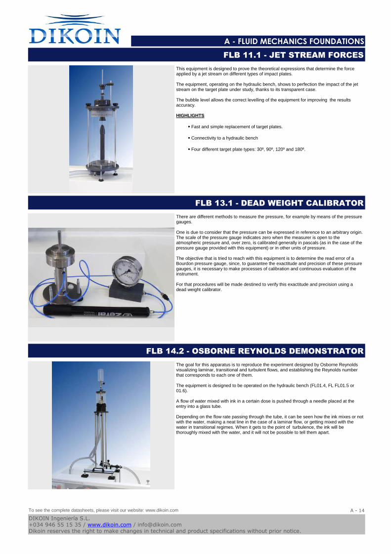
This equipment is designed to prove the theoretical expressions that determine the force applied by a jet stream on different types of impact plates.
The equipment, operating on the hydraulic bench, shows to perfection the impact of the jet stream on the target plate under study, thanks to its transparent case.
The bubble level allows the correct levelling of the equipment for improving the results accuracy.
HIGHLIGHTS
⦁ Fast and simple replacement of target plates.
⦁ Connectivity to a hydraulic bench
⦁ Four different target plate types: 30º, 90º, 120º and 180º.
FLB 11.1 - JET STREAM FORCES
There are different methods to measure the pressure, for example by means of the pressure gauges.
One is due to consider that the pressure can be expressed in reference to an arbitrary origin. The scale of the pressure gauge indicates zero when the measurer is open to the atmospheric pressure and, over zero, is calibrated generally in pascals (as in the case of the pressure gauge provided with this equipment) or in other units of pressure.
The objective that is tried to reach with this equipment is to determine the read error of a Bourdon pressure gauge, since, to guarantee the exactitude and precision of these pressure gauges, it is necessary to make processes of calibration and continuous evaluation of the instrument.
For that procedures will be made destined to verify this exactitude and precision using a dead weight calibrator.
FLB 13.1 - DEAD WEIGHT CALIBRATOR
The goal for this apparatus is to reproduce the experiment designed by Osborne Reynolds visualizing laminar, transitional and turbulent flows, and establishing the Reynolds number that corresponds to each one of them.
The equipment is designed to be operated on the hydraulic bench (FL01.4, FL FL01.5 or 01.6).
A flow of water mixed with ink in a certain dose is pushed through a needle placed at the entry into a glass tube.
Depending on the flow rate passing through the tube, it can be seen how the ink mixes or not with the water, making a neat line in the case of a laminar flow, or getting mixed with the water in transitional regimes. When it gets to the point of turbulence, the ink will be thoroughly mixed with the water, and it will not be possible to tell them apart.
FLB 14.2 - OSBORNE REYNOLDS DEMONSTRATOR
To see the complete datasheets, please visit our website: www.dikoin.com
Catalogos-Pie19A - 14
DIKOIN Ingeniería S.L.+034 946 55 15 35 / www.dikoin.com / [email protected] reserves the right to make changes in technical and product specifications without prior notice.
Logo-DK
A - FLUID MECHANICS FOUNDATIONS
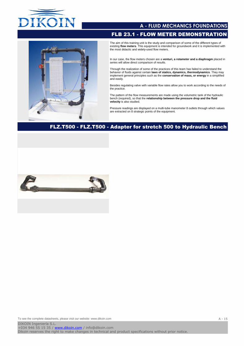
The aim of this training unit is the study and comparison of some of the different types of existing flow meters. This equipment is intended for groundwork and it is implemented with the most didactic and widely-used flow meters.
In our case, the flow meters chosen are a venturi, a rotameter and a diaphragm placed in series will allow direct comparison of results.
Through the realization of some of the practices of this team has failed to understand the behavior of fluids against certain laws of statics, dynamics, thermodynamics. They may implement general principles such as the conservation of mass, or energy in a simplified and easily.
Besides regulating valve with variable flow rates allow you to work according to the needs of the practice.
The pattern of the flow measurements are made using the volumetric tank of the hydraulic bench (required), so that the relationship between the pressure drop and the fluid velocity is also studied.
Pressure readings are displayed on a multi-tube manometer 8 outlets through which values are extracted on 8 strategic points of the equipment.
FLB 23.1 - FLOW METER DEMONSTRATION
FLZ.T500 - FLZ.T500 - Adapter for stretch 500 to Hydraulic Bench
To see the complete datasheets, please visit our website: www.dikoin.com
Catalogos-Pie19A - 15
DIKOIN Ingeniería S.L.+034 946 55 15 35 / www.dikoin.com / [email protected] reserves the right to make changes in technical and product specifications without prior notice.
B - HYDRAULIC MACHINES
Logo-DK
FL 03.1 - SERIES AND PARALLEL PUMPS (pag. B - 1) FL 03.2 - CENTRIFUGAL PUMPS CHARACTERISTICS (pag.
B - 1)
FL 07.1 - AXIAL FAN (pag. B - 1)
FL 07.2 - CENTRIFUGAL FAN (pag. B - 2) MH 01.1 - CENTRIFUGAL PUMP DEMONSTRATION UNIT
(pag. B - 2)
MH 05.1 - VISUALIZATION NPSH EQUIPMENT (pag. B - 2)
TH 01.1 - FRICTION BRAKE PELTON TURBINE (pag. B - 3) TH 01.2 - FRICTION BRAKE FRANCIS TURBINE (pag. B - 3) TH 01.4 - FRICTION BRAKE KAPLAN TURBINE (pag. B - 3)
TH 03.1 - ELECTRIC BRAKE PELTON TURBINE (pag. B - 4) TH 03.2 - ELECTRIC BRAKE FRANCIS TURBINE (pag. B - 4) TH 03.4 - ELECTRIC BRAKE KAPLAN TURBINE (pag. B - 4)
TH 04.1 - AUTONOMOUS ELECTRIC BRAKE PELTON
TURBINE (pag. B - 5)
TH 04.2 - AUTONOMOUS ELECTRIC BRAKE FRANCIS
TURBINE (pag. B - 5)
TH 04.4 - AUTONOMOUS ELECTRIC BRAKE KAPLAN
TURBINE (pag. B - 5)
Catalogos-Pie19DIKOIN Ingeniería S.L.+034 946 55 15 35 / www.dikoin.com / [email protected] reserves the right to make changes in technical and product specifications without prior notice.
Logo-DK
B - HYDRAULIC MACHINES
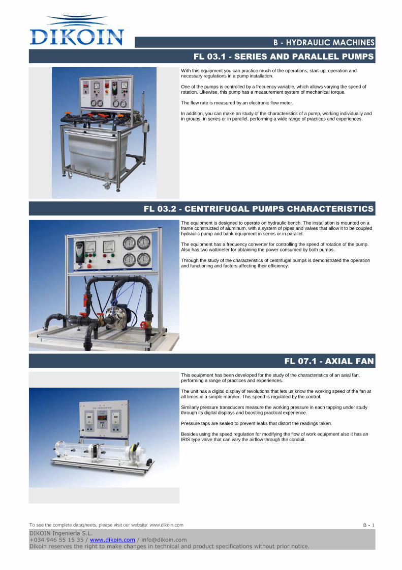
With this equipment you can practice much of the operations, start-up, operation and necessary regulations in a pump installation.
One of the pumps is controlled by a frecuency variable, which allows varying the speed of rotation. Likewise, this pump has a measurement system of mechanical torque.
The flow rate is measured by an electronic flow meter.
In addition, you can make an study of the characteristics of a pump, working individually and in groups, in series or in parallel, performing a wide range of practices and experiences.
FL 03.1 - SERIES AND PARALLEL PUMPS
The equipment is designed to operate on hydraulic bench. The installation is mounted on a frame constructed of aluminum, with a system of pipes and valves that allow it to be coupled hydraulic pump and bank equipment in series or in parallel.
The equipment has a frequency converter for controlling the speed of rotation of the pump. Also has two wattmeter for obtaining the power consumed by both pumps.
Through the study of the characteristics of centrifugal pumps is demonstrated the operation and functioning and factors affecting their efficiency.
FL 03.2 - CENTRIFUGAL PUMPS CHARACTERISTICS
This equipment has been developed for the study of the characteristics of an axial fan, performing a range of practices and experiences.
The unit has a digital display of revolutions that lets us know the working speed of the fan at all times in a simple manner. This speed is regulated by the control.
Similarly pressure transducers measure the working pressure in each tapping under study through its digital displays and boosting practical experience.
Pressure taps are sealed to prevent leaks that distort the readings taken.
Besides using the speed regulation for modifying the flow of work equipment also it has an IRIS type valve that can vary the airflow through the conduit.
FL 07.1 - AXIAL FAN
To see the complete datasheets, please visit our website: www.dikoin.com
Catalogos-Pie19B - 1
DIKOIN Ingeniería S.L.+034 946 55 15 35 / www.dikoin.com / [email protected] reserves the right to make changes in technical and product specifications without prior notice.
Logo-DK
B - HYDRAULIC MACHINES
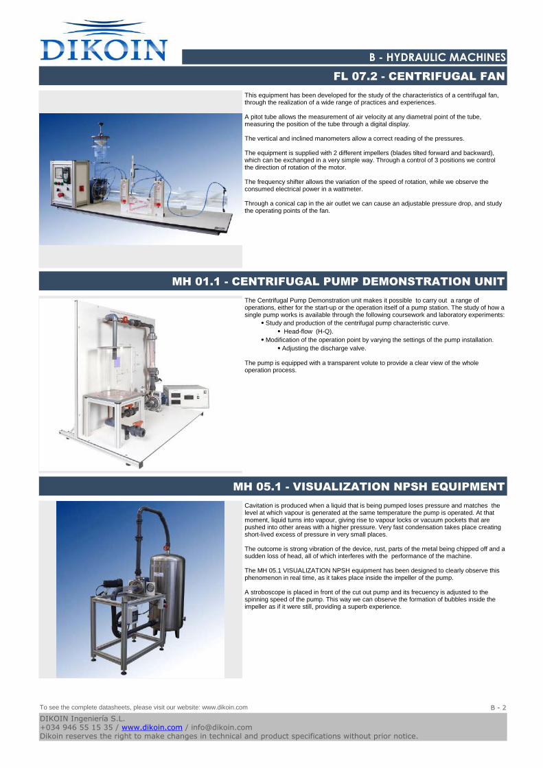
This equipment has been developed for the study of the characteristics of a centrifugal fan, through the realization of a wide range of practices and experiences.
A pitot tube allows the measurement of air velocity at any diametral point of the tube, measuring the position of the tube through a digital display.
The vertical and inclined manometers allow a correct reading of the pressures.
The equipment is supplied with 2 different impellers (blades tilted forward and backward), which can be exchanged in a very simple way. Through a control of 3 positions we control the direction of rotation of the motor.
The frequency shifter allows the variation of the speed of rotation, while we observe the consumed electrical power in a wattmeter.
Through a conical cap in the air outlet we can cause an adjustable pressure drop, and study the operating points of the fan.
FL 07.2 - CENTRIFUGAL FAN
The Centrifugal Pump Demonstration unit makes it possible to carry out a range of operations, either for the start-up or the operation itself of a pump station. The study of how a single pump works is available through the following coursework and laboratory experiments:
⦁ Study and production of the centrifugal pump characteristic curve.
⦁ Head-flow (H-Q).
⦁ Modification of the operation point by varying the settings of the pump installation.
⦁ Adjusting the discharge valve.
The pump is equipped with a transparent volute to provide a clear view of the whole operation process.
MH 01.1 - CENTRIFUGAL PUMP DEMONSTRATION UNIT
Cavitation is produced when a liquid that is being pumped loses pressure and matches the level at which vapour is generated at the same temperature the pump is operated. At that moment, liquid turns into vapour, giving rise to vapour locks or vacuum pockets that are pushed into other areas with a higher pressure. Very fast condensation takes place creating short-lived excess of pressure in very small places.
The outcome is strong vibration of the device, rust, parts of the metal being chipped off and a sudden loss of head, all of which interferes with the performance of the machine.
The MH 05.1 VISUALIZATION NPSH equipment has been designed to clearly observe this phenomenon in real time, as it takes place inside the impeller of the pump.
A stroboscope is placed in front of the cut out pump and its frecuency is adjusted to the spinning speed of the pump. This way we can observe the formation of bubbles inside the impeller as if it were still, providing a superb experience.
MH 05.1 - VISUALIZATION NPSH EQUIPMENT
To see the complete datasheets, please visit our website: www.dikoin.com
Catalogos-Pie19B - 2
DIKOIN Ingeniería S.L.+034 946 55 15 35 / www.dikoin.com / [email protected] reserves the right to make changes in technical and product specifications without prior notice.
Logo-DK
B - HYDRAULIC MACHINES
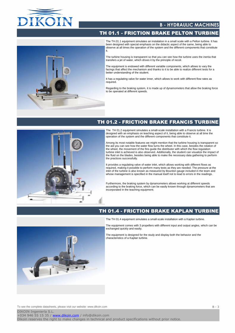
The TH.01.1 equipment simulates an instalation in a small scale with a Pelton turbine. It has been designed with special emphasis on the didactic aspect of the same, being able to observe at all times the operation of the system and the different components that constitute it.
The turbine housing is transparent so that you can see how the turbine uses the inertia that transfers a jet of water, which drives it by the principle of recoil.
The equipment is endowed with different variable components, which allows to vary the facings that affect the mechanism and thanks to it to be able to realize different tests for a better understanding of the student.
It has a regulating valve for water inner, which allows to work with different flow rates as required.
Regarding to the braking system, it is made up of dynamometers that allow the braking force to be operated at different speeds.
TH 01.1 - FRICTION BRAKE PELTON TURBINE
The TH 01.2 equipment simulates a small-scale installation with a Francis turbine. It is designed with an emphasis on teaching aspect of it, being able to observe at all time the operation of the system and the different components that constitute it.
Among its most notable features we might mention that the turbine housing is transparent so the aid you can see how the water flow turns the wheel. In this case, besides the rotation of the wheel, the movement of the fins guide the distributor with which the flow regulation turbine inlet is achieved is also observed. Additionally, the student can visualize the impact of the fluid on the blades, besides being able to make the necessary data gathering to perform the practices successfully.
It provides a regulating valve of water inlet, which allows working with different flows as required, making it possible to perform many tests as they are needed. The pressure at the inlet of the turbine is also known as measured by Bourdon gauge included in the team and whose management is specified in the manual itself not to lead to errors in the readings.
Furthermore, the braking system by dynamometers allows working at different speeds according to the braking force, which can be easily known through dynamometers that are incorporated in the teaching equipment.
TH 01.2 - FRICTION BRAKE FRANCIS TURBINE
The TH 01.4 equipment simulates a small-scale installation with a Kaplan turbine.
The equipment comes with 3 propellers with different input and output angles, which can be exchanged quickly and easily.
The equipment is designed for the study and display both the behavior and the characteristics of a Kaplan turbine.
TH 01.4 - FRICTION BRAKE KAPLAN TURBINE
To see the complete datasheets, please visit our website: www.dikoin.com
Catalogos-Pie19B - 3
DIKOIN Ingeniería S.L.+034 946 55 15 35 / www.dikoin.com / [email protected] reserves the right to make changes in technical and product specifications without prior notice.
Logo-DK
B - HYDRAULIC MACHINES
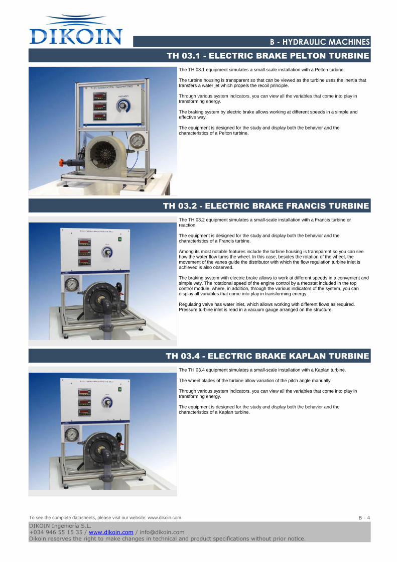
The TH 03.1 equipment simulates a small-scale installation with a Pelton turbine.
The turbine housing is transparent so that can be viewed as the turbine uses the inertia that transfers a water jet which propels the recoil principle.
Through various system indicators, you can view all the variables that come into play in transforming energy.
The braking system by electric brake allows working at different speeds in a simple and effective way.
The equipment is designed for the study and display both the behavior and the characteristics of a Pelton turbine.
TH 03.1 - ELECTRIC BRAKE PELTON TURBINE
The TH 03.2 equipment simulates a small-scale installation with a Francis turbine or reaction.
The equipment is designed for the study and display both the behavior and the characteristics of a Francis turbine.
Among its most notable features include the turbine housing is transparent so you can see how the water flow turns the wheel. In this case, besides the rotation of the wheel, the movement of the vanes guide the distributor with which the flow regulation turbine inlet is achieved is also observed.
The braking system with electric brake allows to work at different speeds in a convenient and simple way. The rotational speed of the engine control by a rheostat included in the top control module, where, in addition, through the various indicators of the system, you can display all variables that come into play in transforming energy.
Regulating valve has water inlet, which allows working with different flows as required. Pressure turbine inlet is read in a vacuum gauge arranged on the structure.
TH 03.2 - ELECTRIC BRAKE FRANCIS TURBINE
The TH 03.4 equipment simulates a small-scale installation with a Kaplan turbine.
The wheel blades of the turbine allow variation of the pitch angle manually.
Through various system indicators, you can view all the variables that come into play in transforming energy.
The equipment is designed for the study and display both the behavior and the characteristics of a Kaplan turbine.
TH 03.4 - ELECTRIC BRAKE KAPLAN TURBINE
To see the complete datasheets, please visit our website: www.dikoin.com
Catalogos-Pie19B - 4
DIKOIN Ingeniería S.L.+034 946 55 15 35 / www.dikoin.com / [email protected] reserves the right to make changes in technical and product specifications without prior notice.
Logo-DK
B - HYDRAULIC MACHINES
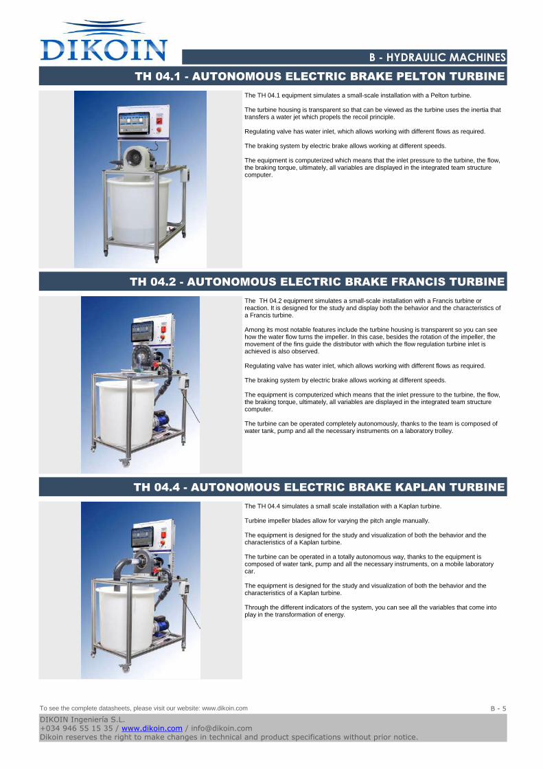
The TH 04.1 equipment simulates a small-scale installation with a Pelton turbine.
The turbine housing is transparent so that can be viewed as the turbine uses the inertia that transfers a water jet which propels the recoil principle.
Regulating valve has water inlet, which allows working with different flows as required.
The braking system by electric brake allows working at different speeds.
The equipment is computerized which means that the inlet pressure to the turbine, the flow, the braking torque, ultimately, all variables are displayed in the integrated team structure computer.
TH 04.1 - AUTONOMOUS ELECTRIC BRAKE PELTON TURBINE
The TH 04.2 equipment simulates a small-scale installation with a Francis turbine or reaction. It is designed for the study and display both the behavior and the characteristics of a Francis turbine.
Among its most notable features include the turbine housing is transparent so you can see how the water flow turns the impeller. In this case, besides the rotation of the impeller, the movement of the fins guide the distributor with which the flow regulation turbine inlet is achieved is also observed.
Regulating valve has water inlet, which allows working with different flows as required.
The braking system by electric brake allows working at different speeds.
The equipment is computerized which means that the inlet pressure to the turbine, the flow, the braking torque, ultimately, all variables are displayed in the integrated team structure computer.
The turbine can be operated completely autonomously, thanks to the team is composed of water tank, pump and all the necessary instruments on a laboratory trolley.
TH 04.2 - AUTONOMOUS ELECTRIC BRAKE FRANCIS TURBINE
The TH 04.4 simulates a small scale installation with a Kaplan turbine.
Turbine impeller blades allow for varying the pitch angle manually.
The equipment is designed for the study and visualization of both the behavior and the characteristics of a Kaplan turbine.
The turbine can be operated in a totally autonomous way, thanks to the equipment is composed of water tank, pump and all the necessary instruments, on a mobile laboratory car. The equipment is designed for the study and visualization of both the behavior and the characteristics of a Kaplan turbine.
Through the different indicators of the system, you can see all the variables that come into play in the transformation of energy.
TH 04.4 - AUTONOMOUS ELECTRIC BRAKE KAPLAN TURBINE
To see the complete datasheets, please visit our website: www.dikoin.com
Catalogos-Pie19B - 5
DIKOIN Ingeniería S.L.+034 946 55 15 35 / www.dikoin.com / [email protected] reserves the right to make changes in technical and product specifications without prior notice.
C - HYDRAULICS, HYDROLOGY AND WATER TREATMENT
Logo-DK
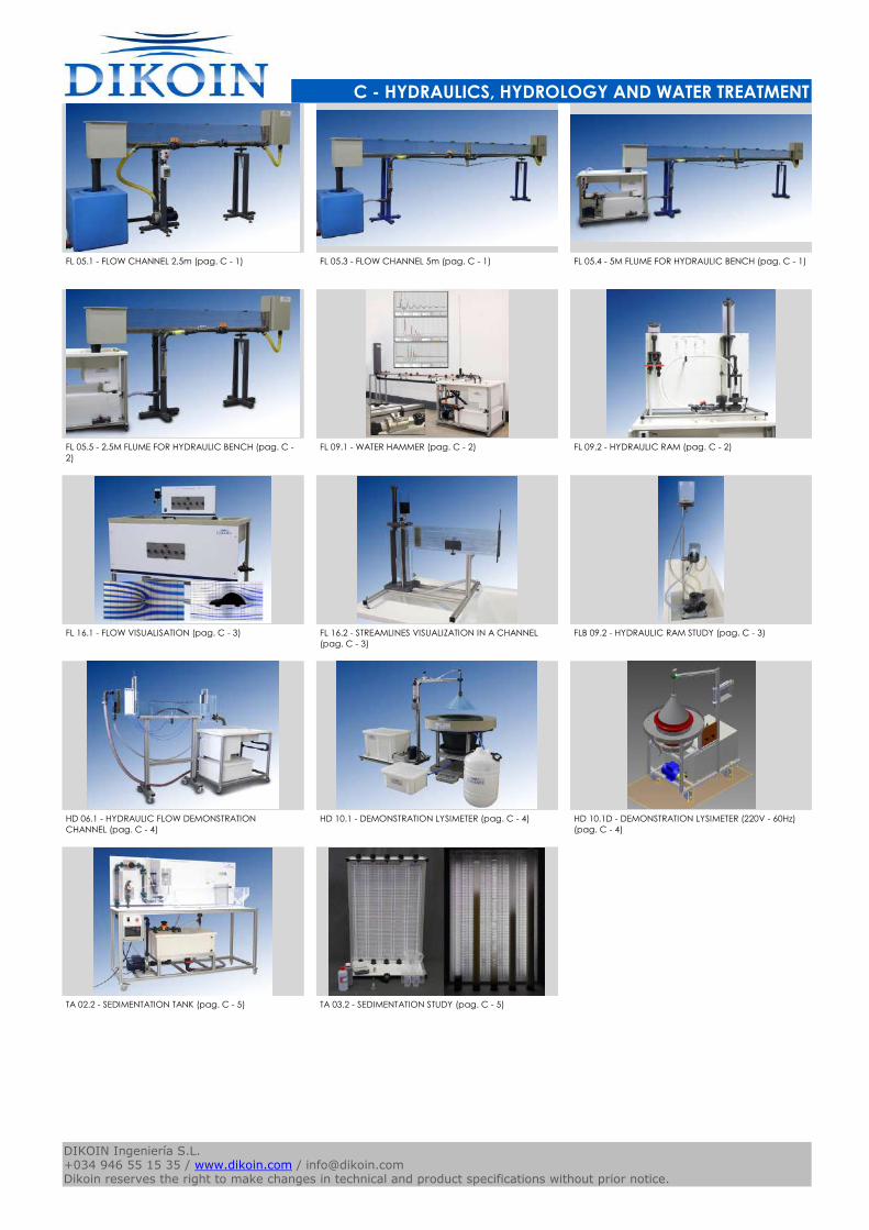
FL 05.1 - FLOW CHANNEL 2,5m (pag. C - 1) FL 05.3 - FLOW CHANNEL 5m (pag. C - 1) FL 05.4 - 5M FLUME FOR HYDRAULIC BENCH (pag. C - 1)
FL 05.5 - 2,5M FLUME FOR HYDRAULIC BENCH (pag. C -
2)
FL 09.1 - WATER HAMMER (pag. C - 2) FL 09.2 - HYDRAULIC RAM (pag. C - 2)
FL 16.1 - FLOW VISUALISATION (pag. C - 3) FL 16.2 - STREAMLINES VISUALIZATION IN A CHANNEL
(pag. C - 3)
FLB 09.2 - HYDRAULIC RAM STUDY (pag. C - 3)
HD 06.1 - HYDRAULIC FLOW DEMONSTRATION
CHANNEL (pag. C - 4)
HD 10.1 - DEMONSTRATION LYSIMETER (pag. C - 4) HD 10.1D - DEMONSTRATION LYSIMETER (220V - 60Hz)
(pag. C - 4)
TA 02.2 - SEDIMENTATION TANK (pag. C - 5) TA 03.2 - SEDIMENTATION STUDY (pag. C - 5)
Catalogos-Pie19DIKOIN Ingeniería S.L.+034 946 55 15 35 / www.dikoin.com / [email protected] reserves the right to make changes in technical and product specifications without prior notice.
Logo-DK
C - HYDRAULICS, HYDROLOGY AND WATER TREATMENT
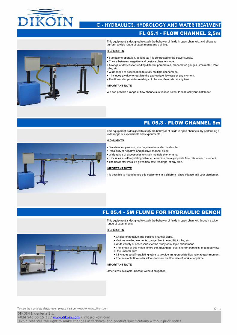
This equipment is designed to study the behavior of fluids in open channels, and allows to perform a wide range of experiments and training.
HIGHLIGHTS
⦁ Standalone operation, as long as it is connected to the power supply.
⦁ Choice between negative and positive channel slope.
⦁ A range of devices for reading different parametres, manometric gauges, limnimeter, Pitot tube, etc.
⦁ Wide range of accessories to study multiple phenomena.
⦁ It includes a valve to regulate the appropriate flow rate at any moment.
⦁ The flowmeter provides readings of the workflow rate at any time.
IMPORTANT NOTE
We can provide a range of flow channels in various sizes. Please ask your distributor.
FL 05.1 - FLOW CHANNEL 2,5m
This equipment is designed to study the behavior of fluids in open channels, by performing a wide range of experiments and experiments.
HIGHLIGHTS
⦁ Standalone operation, you only need one electrical outlet.
⦁ Possibility of negative and positive channel slope.
⦁ Wide range of accessories to study multiple phenomena.
⦁ It includes a self-regulating valve to determine the appropriate flow rate at each moment.
⦁ The flowmeter installed gives flow-rate readings at any time.
IMPORTANT NOTE
It is possible to manufacture this equipment in a different sizes. Please ask your distributor.
FL 05.3 - FLOW CHANNEL 5m
This equipment is designed to study the behavior of fluids in open channels through a wide range of experiments.
HIGHLIGHTS
⦁ Choice of negative and positive channel slope.
⦁ Various reading elements, gauge, limnimeter, Pitot tube, etc.
⦁ Wide variety of accessories for the study of multiple phenomena.
⦁ The length of this model offers the advantage, over shorter channels, of a good view of the uniform flow.
⦁ It includes a self-regulating valve to provide an appropriate flow rate at each moment.
⦁ The available flowmeter allows to know the flow rate of work at any time.
IMPORTANT NOTE
Other sizes available. Consult without obligation.
FL 05.4 - 5M FLUME FOR HYDRAULIC BENCH
To see the complete datasheets, please visit our website: www.dikoin.com
Catalogos-Pie19C - 1
DIKOIN Ingeniería S.L.+034 946 55 15 35 / www.dikoin.com / [email protected] reserves the right to make changes in technical and product specifications without prior notice.
Logo-DK
C - HYDRAULICS, HYDROLOGY AND WATER TREATMENT
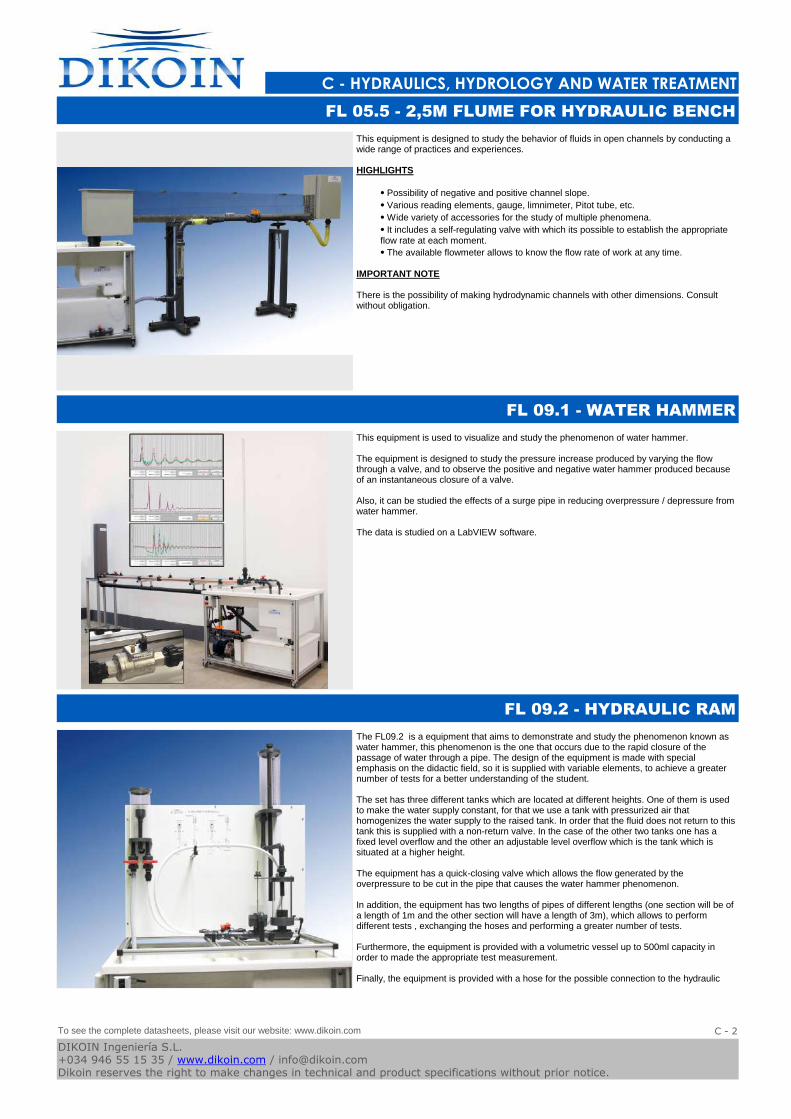
This equipment is designed to study the behavior of fluids in open channels by conducting a wide range of practices and experiences.
HIGHLIGHTS
⦁ Possibility of negative and positive channel slope.
⦁ Various reading elements, gauge, limnimeter, Pitot tube, etc.
⦁ Wide variety of accessories for the study of multiple phenomena.
⦁ It includes a self-regulating valve with which its possible to establish the appropriate flow rate at each moment.
⦁ The available flowmeter allows to know the flow rate of work at any time.
IMPORTANT NOTE
There is the possibility of making hydrodynamic channels with other dimensions. Consult without obligation.
FL 05.5 - 2,5M FLUME FOR HYDRAULIC BENCH
This equipment is used to visualize and study the phenomenon of water hammer.
The equipment is designed to study the pressure increase produced by varying the flow through a valve, and to observe the positive and negative water hammer produced because of an instantaneous closure of a valve.
Also, it can be studied the effects of a surge pipe in reducing overpressure / depressure from water hammer.
The data is studied on a LabVIEW software.
FL 09.1 - WATER HAMMER
The FL09.2 is a equipment that aims to demonstrate and study the phenomenon known as water hammer, this phenomenon is the one that occurs due to the rapid closure of the passage of water through a pipe. The design of the equipment is made with special emphasis on the didactic field, so it is supplied with variable elements, to achieve a greater number of tests for a better understanding of the student.
The set has three different tanks which are located at different heights. One of them is used to make the water supply constant, for that we use a tank with pressurized air that homogenizes the water supply to the raised tank. In order that the fluid does not return to this tank this is supplied with a non-return valve. In the case of the other two tanks one has a fixed level overflow and the other an adjustable level overflow which is the tank which is situated at a higher height.
The equipment has a quick-closing valve which allows the flow generated by the overpressure to be cut in the pipe that causes the water hammer phenomenon.
In addition, the equipment has two lengths of pipes of different lengths (one section will be of a length of 1m and the other section will have a length of 3m), which allows to perform different tests , exchanging the hoses and performing a greater number of tests.
Furthermore, the equipment is provided with a volumetric vessel up to 500ml capacity in order to made the appropriate test measurement.
Finally, the equipment is provided with a hose for the possible connection to the hydraulic
FL 09.2 - HYDRAULIC RAM
To see the complete datasheets, please visit our website: www.dikoin.com
Catalogos-Pie19C - 2
DIKOIN Ingeniería S.L.+034 946 55 15 35 / www.dikoin.com / [email protected] reserves the right to make changes in technical and product specifications without prior notice.
Logo-DK
C - HYDRAULICS, HYDROLOGY AND WATER TREATMENT
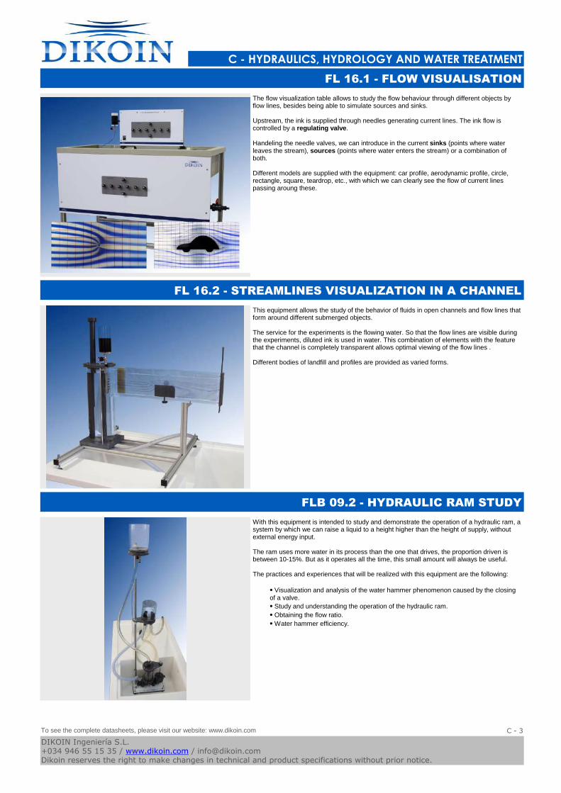
The flow visualization table allows to study the flow behaviour through different objects by flow lines, besides being able to simulate sources and sinks.
Upstream, the ink is supplied through needles generating current lines. The ink flow is controlled by a regulating valve.
Handeling the needle valves, we can introduce in the current sinks (points where water leaves the stream), sources (points where water enters the stream) or a combination of both.
Different models are supplied with the equipment: car profile, aerodynamic profile, circle, rectangle, square, teardrop, etc., with which we can clearly see the flow of current lines passing aroung these.
FL 16.1 - FLOW VISUALISATION
This equipment allows the study of the behavior of fluids in open channels and flow lines that form around different submerged objects.
The service for the experiments is the flowing water. So that the flow lines are visible during the experiments, diluted ink is used in water. This combination of elements with the feature that the channel is completely transparent allows optimal viewing of the flow lines .
Different bodies of landfill and profiles are provided as varied forms.
FL 16.2 - STREAMLINES VISUALIZATION IN A CHANNEL
With this equipment is intended to study and demonstrate the operation of a hydraulic ram, a system by which we can raise a liquid to a height higher than the height of supply, without external energy input.
The ram uses more water in its process than the one that drives, the proportion driven is between 10-15%. But as it operates all the time, this small amount will always be useful.
The practices and experiences that will be realized with this equipment are the following:
⦁ Visualization and analysis of the water hammer phenomenon caused by the closing of a valve.
⦁ Study and understanding the operation of the hydraulic ram.
⦁ Obtaining the flow ratio.
⦁ Water hammer efficiency.
FLB 09.2 - HYDRAULIC RAM STUDY
To see the complete datasheets, please visit our website: www.dikoin.com
Catalogos-Pie19C - 3
DIKOIN Ingeniería S.L.+034 946 55 15 35 / www.dikoin.com / [email protected] reserves the right to make changes in technical and product specifications without prior notice.
Logo-DK
C - HYDRAULICS, HYDROLOGY AND WATER TREATMENT
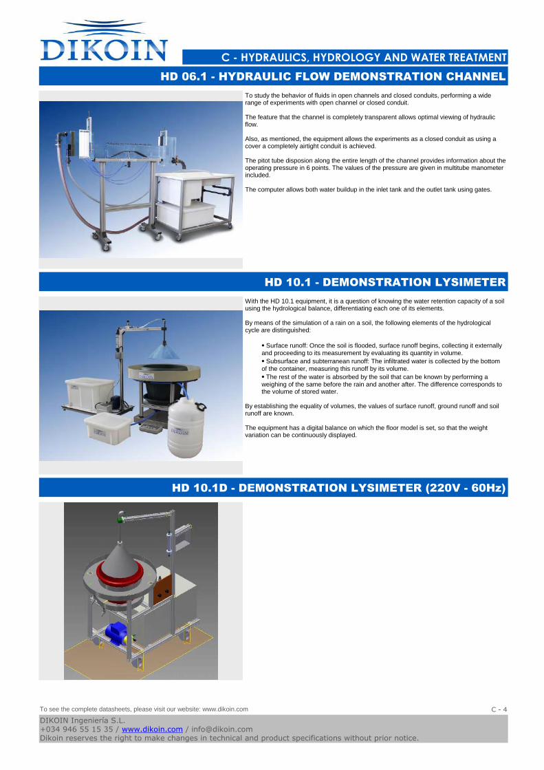
To study the behavior of fluids in open channels and closed conduits, performing a wide range of experiments with open channel or closed conduit.
The feature that the channel is completely transparent allows optimal viewing of hydraulic flow.
Also, as mentioned, the equipment allows the experiments as a closed conduit as using a cover a completely airtight conduit is achieved.
The pitot tube disposion along the entire length of the channel provides information about the operating pressure in 6 points. The values of the pressure are given in multitube manometer included.
The computer allows both water buildup in the inlet tank and the outlet tank using gates.
HD 06.1 - HYDRAULIC FLOW DEMONSTRATION CHANNEL
With the HD 10.1 equipment, it is a question of knowing the water retention capacity of a soil using the hydrological balance, differentiating each one of its elements.
By means of the simulation of a rain on a soil, the following elements of the hydrological cycle are distinguished:
⦁ Surface runoff: Once the soil is flooded, surface runoff begins, collecting it externally and proceeding to its measurement by evaluating its quantity in volume.
⦁ Subsurface and subterranean runoff: The infiltrated water is collected by the bottom of the container, measuring this runoff by its volume.
⦁ The rest of the water is absorbed by the soil that can be known by performing a weighing of the same before the rain and another after. The difference corresponds to the volume of stored water.
By establishing the equality of volumes, the values of surface runoff, ground runoff and soil runoff are known.
The equipment has a digital balance on which the floor model is set, so that the weight variation can be continuously displayed.
HD 10.1 - DEMONSTRATION LYSIMETER
HD 10.1D - DEMONSTRATION LYSIMETER (220V - 60Hz)
To see the complete datasheets, please visit our website: www.dikoin.com
Catalogos-Pie19C - 4
DIKOIN Ingeniería S.L.+034 946 55 15 35 / www.dikoin.com / [email protected] reserves the right to make changes in technical and product specifications without prior notice.
Logo-DK
C - HYDRAULICS, HYDROLOGY AND WATER TREATMENT
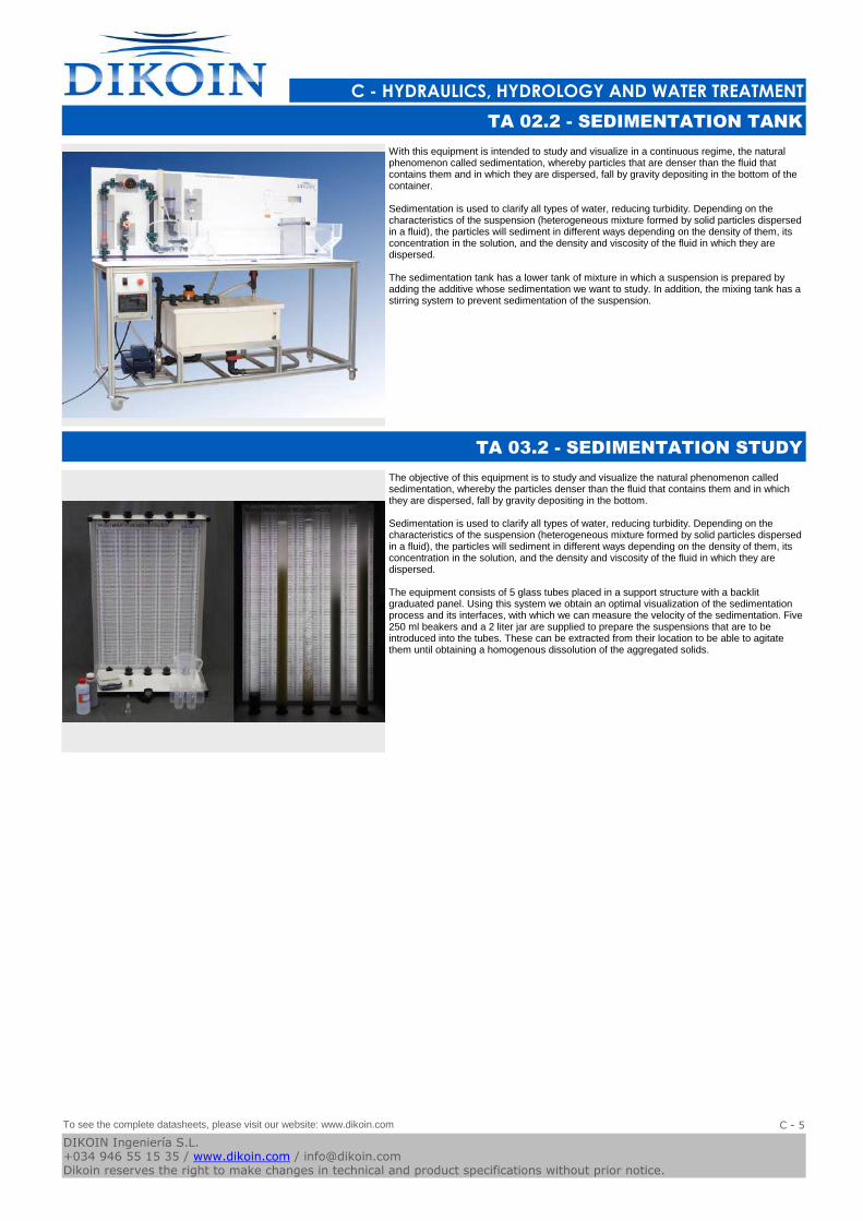
With this equipment is intended to study and visualize in a continuous regime, the natural phenomenon called sedimentation, whereby particles that are denser than the fluid that contains them and in which they are dispersed, fall by gravity depositing in the bottom of the container.
Sedimentation is used to clarify all types of water, reducing turbidity. Depending on the characteristics of the suspension (heterogeneous mixture formed by solid particles dispersed in a fluid), the particles will sediment in different ways depending on the density of them, its concentration in the solution, and the density and viscosity of the fluid in which they are dispersed.
The sedimentation tank has a lower tank of mixture in which a suspension is prepared by adding the additive whose sedimentation we want to study. In addition, the mixing tank has a stirring system to prevent sedimentation of the suspension.
TA 02.2 - SEDIMENTATION TANK
The objective of this equipment is to study and visualize the natural phenomenon called sedimentation, whereby the particles denser than the fluid that contains them and in which they are dispersed, fall by gravity depositing in the bottom.
Sedimentation is used to clarify all types of water, reducing turbidity. Depending on the characteristics of the suspension (heterogeneous mixture formed by solid particles dispersed in a fluid), the particles will sediment in different ways depending on the density of them, its concentration in the solution, and the density and viscosity of the fluid in which they are dispersed.
The equipment consists of 5 glass tubes placed in a support structure with a backlit graduated panel. Using this system we obtain an optimal visualization of the sedimentation process and its interfaces, with which we can measure the velocity of the sedimentation. Five 250 ml beakers and a 2 liter jar are supplied to prepare the suspensions that are to be introduced into the tubes. These can be extracted from their location to be able to agitate them until obtaining a homogenous dissolution of the aggregated solids.
TA 03.2 - SEDIMENTATION STUDY
To see the complete datasheets, please visit our website: www.dikoin.com
Catalogos-Pie19C - 5
DIKOIN Ingeniería S.L.+034 946 55 15 35 / www.dikoin.com / [email protected] reserves the right to make changes in technical and product specifications without prior notice.

D - AERODYNAMICS
Logo-DK
AD 01.1 - AERODYNAMICS BENCH (pag. D - 1) FL 07.1 - AXIAL FAN (pag. D - 1) FL 07.2 - CENTRIFUGAL FAN (pag. D - 1)
Catalogos-Pie19DIKOIN Ingeniería S.L.+034 946 55 15 35 / www.dikoin.com / [email protected] reserves the right to make changes in technical and product specifications without prior notice.
Logo-DK
D - AERODYNAMICS
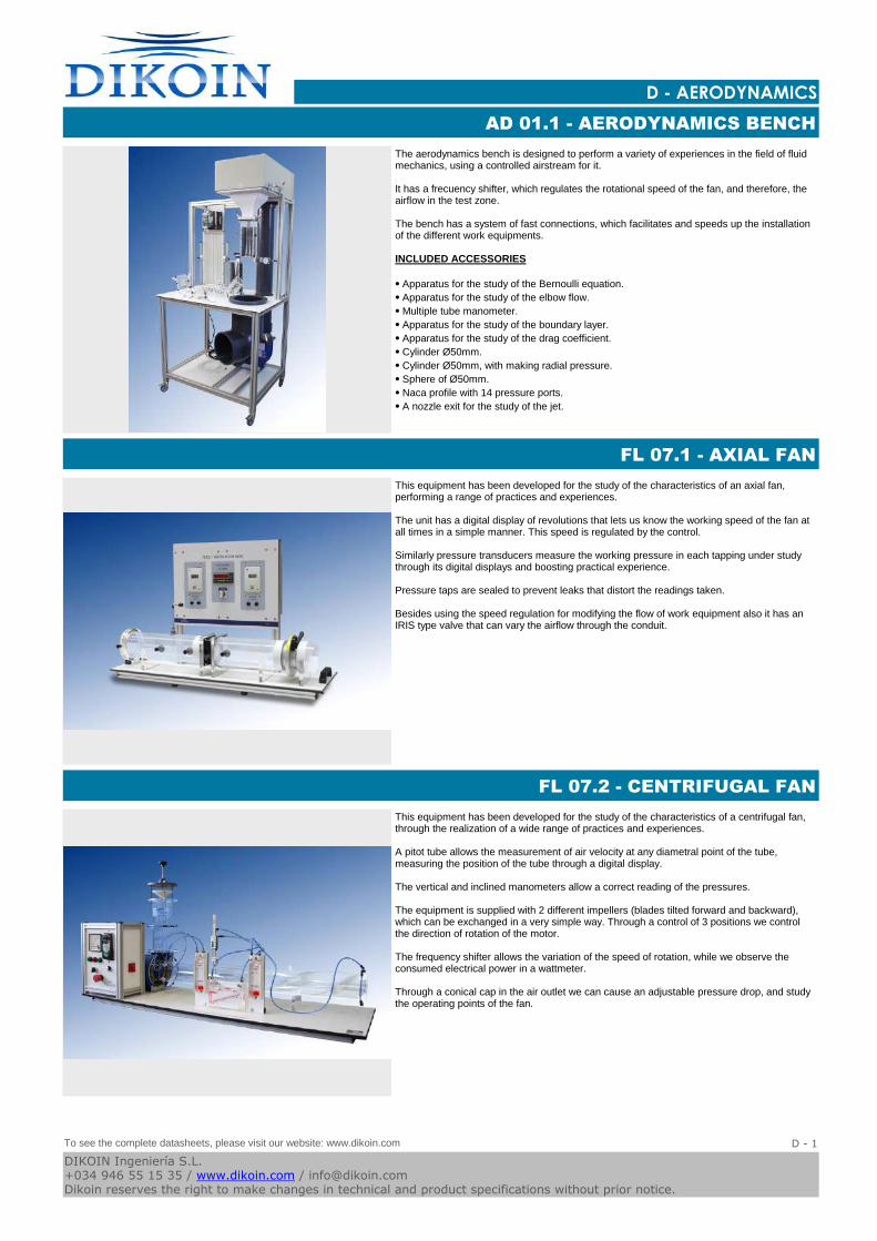
The aerodynamics bench is designed to perform a variety of experiences in the field of fluid mechanics, using a controlled airstream for it.
It has a frecuency shifter, which regulates the rotational speed of the fan, and therefore, the airflow in the test zone.
The bench has a system of fast connections, which facilitates and speeds up the installation of the different work equipments.
INCLUDED ACCESSORIES
⦁ Apparatus for the study of the Bernoulli equation.
⦁ Apparatus for the study of the elbow flow.
⦁ Multiple tube manometer.
⦁ Apparatus for the study of the boundary layer.
⦁ Apparatus for the study of the drag coefficient.
⦁ Cylinder Ø50mm.
⦁ Cylinder Ø50mm, with making radial pressure.
⦁ Sphere of Ø50mm.
⦁ Naca profile with 14 pressure ports.
⦁ A nozzle exit for the study of the jet.
AD 01.1 - AERODYNAMICS BENCH
This equipment has been developed for the study of the characteristics of an axial fan, performing a range of practices and experiences.
The unit has a digital display of revolutions that lets us know the working speed of the fan at all times in a simple manner. This speed is regulated by the control.
Similarly pressure transducers measure the working pressure in each tapping under study through its digital displays and boosting practical experience.
Pressure taps are sealed to prevent leaks that distort the readings taken.
Besides using the speed regulation for modifying the flow of work equipment also it has an IRIS type valve that can vary the airflow through the conduit.
FL 07.1 - AXIAL FAN
This equipment has been developed for the study of the characteristics of a centrifugal fan, through the realization of a wide range of practices and experiences.
A pitot tube allows the measurement of air velocity at any diametral point of the tube, measuring the position of the tube through a digital display.
The vertical and inclined manometers allow a correct reading of the pressures.
The equipment is supplied with 2 different impellers (blades tilted forward and backward), which can be exchanged in a very simple way. Through a control of 3 positions we control the direction of rotation of the motor.
The frequency shifter allows the variation of the speed of rotation, while we observe the consumed electrical power in a wattmeter.
Through a conical cap in the air outlet we can cause an adjustable pressure drop, and study the operating points of the fan.
FL 07.2 - CENTRIFUGAL FAN
To see the complete datasheets, please visit our website: www.dikoin.com
Catalogos-Pie19D - 1
DIKOIN Ingeniería S.L.+034 946 55 15 35 / www.dikoin.com / [email protected] reserves the right to make changes in technical and product specifications without prior notice.
E - RENEWABLE ENERGY
Logo-DK
EN 01.4 - STAND ALONE PHOTOVOLTAIC INSTALLATION
DEMONSTRATOR (pag. E - 1)
EN 01.4PC - (pag. E - 1) EN 01.5 - STAND ALONE AND NETWORK CONNECTED
PHOTOVOLTAIC INSTALLATION DEMONSTRATOR (pag.
E - 1)
EN 01.6 - COMPUTERIZED PHOTOVOLTAIC INSTALLATION
DEMONSTRATOR (pag. E - 2)
EN 04.1 - WINDMILL TEST-BENCH (pag. E - 2) EN 04.3 - GRID CONNECTED DC WINDMILL GENERATOR
TRAINER (pag. E - 2)
EN 04.4 - INSULATED WIND POWER PLANT TRAINER (pag.
E - 3)
EN 05.1 - HYDROELECTRIC PLANT WITH PELTON TURBINE
(pag. E - 3)
EN.S.041 - WINDMILL TEST-BENCH SOFTWARE (pag. E - 3)
Catalogos-Pie19DIKOIN Ingeniería S.L.+034 946 55 15 35 / www.dikoin.com / [email protected] reserves the right to make changes in technical and product specifications without prior notice.
Logo-DK
E - RENEWABLE ENERGY
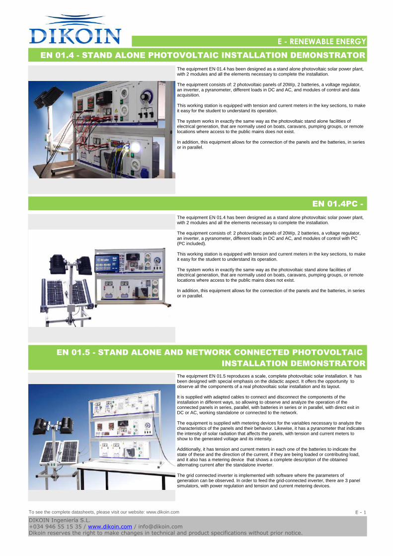
The equipment EN 01.4 has been designed as a stand alone photovoltaic solar power plant, with 2 modules and all the elements necessary to complete the installation.
The equipment consists of: 2 photovoltaic panels of 20Wp, 2 batteries, a voltage regulator, an inverter, a pyranometer, different loads in DC and AC, and modules of control and data acquisition.
This working station is equipped with tension and current meters in the key sections, to make it easy for the student to understand its operation.
The system works in exactly the same way as the photovoltaic stand alone facilities of electrical generation, that are normally used on boats, caravans, pumping groups, or remote locations where access to the public mains does not exist.
In addition, this equipment allows for the connection of the panels and the batteries, in series or in parallel.
EN 01.4 - STAND ALONE PHOTOVOLTAIC INSTALLATION DEMONSTRATOR
The equipment EN 01.4 has been designed as a stand alone photovoltaic solar power plant, with 2 modules and all the elements necessary to complete the installation.
The equipment consists of: 2 photovoltaic panels of 20Wp, 2 batteries, a voltage regulator, an inverter, a pyranometer, different loads in DC and AC, and modules of control with PC (PC included).
This working station is equipped with tension and current meters in the key sections, to make it easy for the student to understand its operation.
The system works in exactly the same way as the photovoltaic stand alone facilities of electrical generation, that are normally used on boats, caravans, pumping groups, or remote locations where access to the public mains does not exist.
In addition, this equipment allows for the connection of the panels and the batteries, in series or in parallel.
EN 01.4PC -
The equipment EN 01.5 reproduces a scale, complete photovoltaic solar installation. It has been designed with special emphasis on the didactic aspect. It offers the opportunity to observe all the components of a real photovoltaic solar installation and its layout.
It is supplied with adapted cables to connect and disconnect the components of the installation in different ways, so allowing to observe and analyze the operation of the connected panels in series, parallel, with batteries in series or in parallel, with direct exit in DC or AC, working standalone or connected to the network.
The equipment is supplied with metering devices for the variables necessary to analyze the characteristics of the panels and their behavior. Likewise, it has a pyranometer that indicates the intensity of solar radiation that affects the panels, with tension and current meters to show to the generated voltage and its intensity.
Additionally, it has tension and current meters in each one of the batteries to indicate the state of these and the direction of the current, if they are being loaded or contributing load, and it also has a metering device that shows a complete description of the obtained alternating current after the standalone inverter.
The grid connected inverter is implemented with software where the parameters of generation can be observed. In order to feed the grid-connected inverter, there are 3 panel simulators, with power regulation and tension and current metering devices.
EN 01.5 - STAND ALONE AND NETWORK CONNECTED PHOTOVOLTAIC
INSTALLATION DEMONSTRATOR
To see the complete datasheets, please visit our website: www.dikoin.com
Catalogos-Pie19E - 1
DIKOIN Ingeniería S.L.+034 946 55 15 35 / www.dikoin.com / [email protected] reserves the right to make changes in technical and product specifications without prior notice.
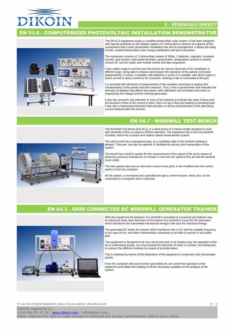
Logo-DK
E - RENEWABLE ENERGY
The EN 01.6 equipment scales a complete photovoltaic solar system. It has been designed with special emphasis on the didactic aspect of it, being able to observe at a glance all the components that a solar photovoltaic installation has and its arrangement. It allows the study of both, isolated photovoltaic solar energy installations and grid connection.
The equipment consists of: 2 photovoltaic panels of 20Wp, 2 batteries, regulator, insulated inverter, grid inverter, solar panel emulator, pyranometer, temperature sensors in panels, various DC and AC loads, and module control and data acquisition.
It has cables ready to connect and disconnect the various elements of the installation in different ways, being able to observe and analyze the operation of the panels connected independently, in series, in parallel, with batteries in series or in parallel, with direct output in Direct current or direct current to AC converter, working in isle or connected to the grid.
It is provided with elements of measurement of the variables necessary to analyze the characteristics of the panels and their behavior. Thus, it has a pyranometer that indicates the intensity of radiation that affects the panels, with voltmeters and ammeters that show us respectively the voltage and the intensity generated.
It also has ammeter and voltmeter in each of the batteries to indicate the state of these and the direction of flow of the current in them, that is to say if they are loading or providing load. It has also a measuring instrument that provides us all the characteristics of the alternating current obtained after the inverter.
EN 01.6 - COMPUTERIZED PHOTOVOLTAIC INSTALLATION DEMONSTRATOR
The Windmill Test-bench (EN 04.1), is a wind tunnel of 2 meters length designed to work with windmills of less or equal to 630mm diameter. The equipment has a 612 mm windmill included, which has a torque and rotation speed measurement system.
The wind tunnel has a transparent part, so a complete sight of the windmill working is allowed. That part, can also be opened, to facilitate the access and manipulation of the system.
The tunnel has a built-in system for the measurement of the speed of the air by means of electronic pressure transducers, to monitor in real time the speed of the air that the windmill is put under.
The new system also has an electronic control of the pitch, to be modified from the control panel or from the computer.
All the system, is monitored and controlled through a control module, which also can be connected to a computer with a USB port.
EN 04.1 - WINDMILL TEST-BENCH
With this equipment the behavior of a windmill is emulated in a practical and didactic way. An electrical motor does the times of the turbine of a windmill to move the DC generator, which transforms the transmitted mechanical energy to the axis into electrical energy.
The generated DC feeds the inverter which transforms this in AC with the suitable frequency, in our case 50 Hz, and other characteristics necessary to be able to connect to the public grid.
The equipment is designed to be very visual and work in an intuitive way, the operation of the set is understood quickly, not only knowing the elements of which it consists, but having also to connect the different modules by means of provided wires.
This is obtained by means of the disposition of the equipment in schematic and connectable panels.
From the computer with touch screen (provided) we can control the operation of the equipment and obtain the reading of all the necessary variables for the analysis of the system.
EN 04.3 - GRID CONNECTED DC WINDMILL GENERATOR TRAINER
To see the complete datasheets, please visit our website: www.dikoin.com
Catalogos-Pie19E - 2
DIKOIN Ingeniería S.L.+034 946 55 15 35 / www.dikoin.com / [email protected] reserves the right to make changes in technical and product specifications without prior notice.
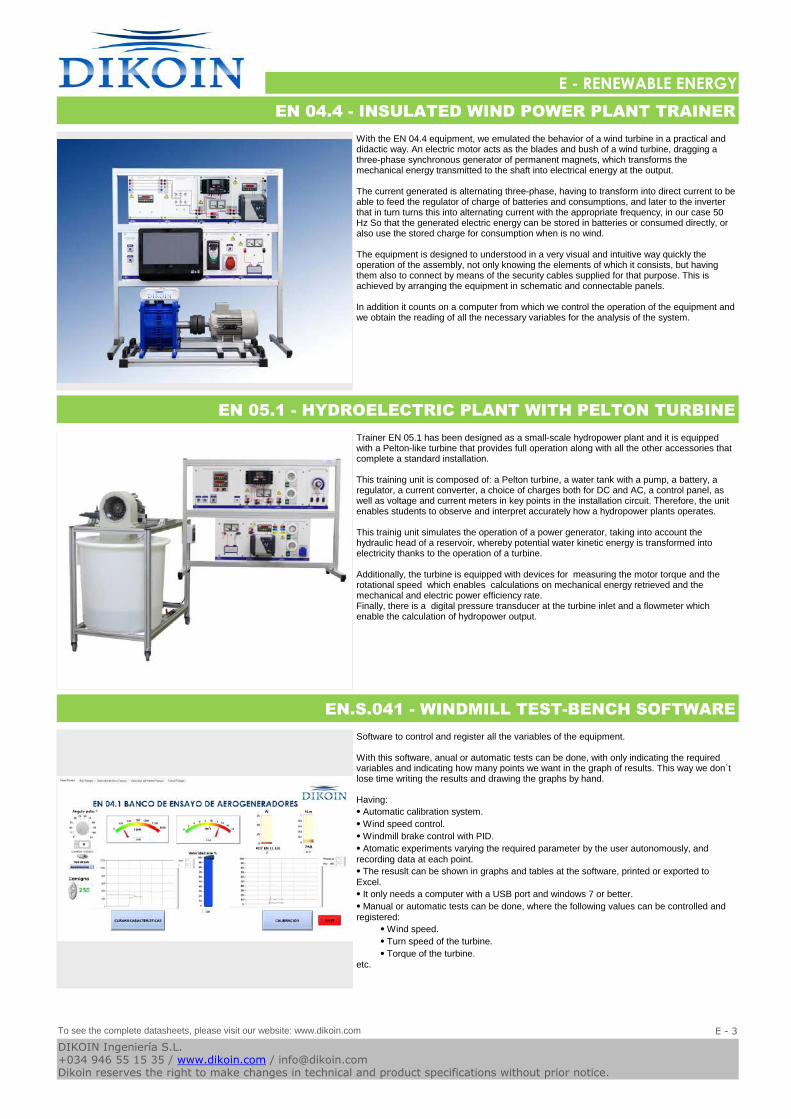
Logo-DK
E - RENEWABLE ENERGY
With the EN 04.4 equipment, we emulated the behavior of a wind turbine in a practical and didactic way. An electric motor acts as the blades and bush of a wind turbine, dragging a three-phase synchronous generator of permanent magnets, which transforms the mechanical energy transmitted to the shaft into electrical energy at the output.
The current generated is alternating three-phase, having to transform into direct current to be able to feed the regulator of charge of batteries and consumptions, and later to the inverter that in turn turns this into alternating current with the appropriate frequency, in our case 50 Hz So that the generated electric energy can be stored in batteries or consumed directly, or also use the stored charge for consumption when is no wind.
The equipment is designed to understood in a very visual and intuitive way quickly the operation of the assembly, not only knowing the elements of which it consists, but having them also to connect by means of the security cables supplied for that purpose. This is achieved by arranging the equipment in schematic and connectable panels.
In addition it counts on a computer from which we control the operation of the equipment and we obtain the reading of all the necessary variables for the analysis of the system.
EN 04.4 - INSULATED WIND POWER PLANT TRAINER
Trainer EN 05.1 has been designed as a small-scale hydropower plant and it is equipped with a Pelton-like turbine that provides full operation along with all the other accessories that complete a standard installation.
This training unit is composed of: a Pelton turbine, a water tank with a pump, a battery, a regulator, a current converter, a choice of charges both for DC and AC, a control panel, as well as voltage and current meters in key points in the installation circuit. Therefore, the unit enables students to observe and interpret accurately how a hydropower plants operates.
This trainig unit simulates the operation of a power generator, taking into account the hydraulic head of a reservoir, whereby potential water kinetic energy is transformed into electricity thanks to the operation of a turbine.
Additionally, the turbine is equipped with devices for measuring the motor torque and the rotational speed which enables calculations on mechanical energy retrieved and the mechanical and electric power efficiency rate. Finally, there is a digital pressure transducer at the turbine inlet and a flowmeter which enable the calculation of hydropower output.
EN 05.1 - HYDROELECTRIC PLANT WITH PELTON TURBINE
Software to control and register all the variables of the equipment.
With this software, anual or automatic tests can be done, with only indicating the required variables and indicating how many points we want in the graph of results. This way we don`t lose time writing the results and drawing the graphs by hand.
Having:
⦁ Automatic calibration system.
⦁ Wind speed control.
⦁ Windmill brake control with PID.
⦁ Atomatic experiments varying the required parameter by the user autonomously, and recording data at each point.
⦁ The resuslt can be shown in graphs and tables at the software, printed or exported to Excel.
⦁ It only needs a computer with a USB port and windows 7 or better.
⦁ Manual or automatic tests can be done, where the following values can be controlled and registered:
⦁ Wind speed.
⦁ Turn speed of the turbine.
⦁ Torque of the turbine.etc.
EN.S.041 - WINDMILL TEST-BENCH SOFTWARE
To see the complete datasheets, please visit our website: www.dikoin.com
Catalogos-Pie19E - 3
DIKOIN Ingeniería S.L.+034 946 55 15 35 / www.dikoin.com / [email protected] reserves the right to make changes in technical and product specifications without prior notice.
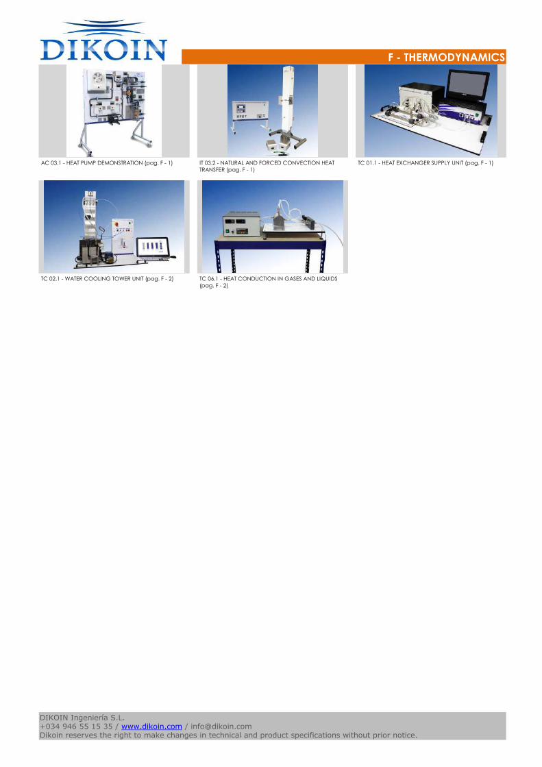
F - THERMODYNAMICS
Logo-DK
AC 03.1 - HEAT PUMP DEMONSTRATION (pag. F - 1) IT 03.2 - NATURAL AND FORCED CONVECTION HEAT
TRANSFER (pag. F - 1)
TC 01.1 - HEAT EXCHANGER SUPPLY UNIT (pag. F - 1)
TC 02.1 - WATER COOLING TOWER UNIT (pag. F - 2) TC 06.1 - HEAT CONDUCTION IN GASES AND LIQUIDS
(pag. F - 2)
Catalogos-Pie19DIKOIN Ingeniería S.L.+034 946 55 15 35 / www.dikoin.com / [email protected] reserves the right to make changes in technical and product specifications without prior notice.
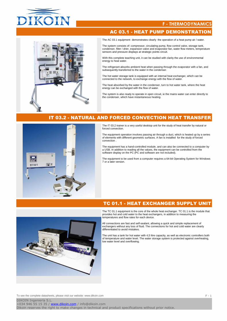
Logo-DK
F - THERMODYNAMICS
The AC 03.1 equipment demonstrates clearly the operation of a heat pump air / water.
The system consists of: compressor, circulating pump, flow control valve, storage tank, condenser, filter / drier, expansion valve and evaporator fan, water flow meters, temperature sensors and pressure displays at strategic points circuit.
With this complete teaching unit, it can be studied with clarity the use of environmental energy to heat water.
The refrigerant absorbs ambient heat when passing through the evaporator with a fan, and subsequently transferred to the water in the condenser.
The hot water storage tank is equipped with an internal heat exchanger, which can be connected to the network, to exchange energy with the flow of water.
The heat absorbed by the water in the condenser, turn to hot water tank, where the heat energy can be exchanged with the flow of water.
The system is also ready to operate in open circuit, ie the mains water can enter directly to the condenser, which have instantaneous heating.
AC 03.1 - HEAT PUMP DEMONSTRATION
The IT 03.2 trainer is a very useful desktop unit for the study of heat transfer by natural or forced convection.
The equipment operation involves passing air through a duct, which is heated up by a series of elements with different geometric surfaces. A fan is installed for the study of forced convection .
The equipment has a hand-controlled module, and can also be connected to a computer by a USB. In addition to reading all the values, the equipment can be controlled from the software display on the PC (PC and software are not included).
The equipment to be used from a computer requires a 64-bit Operating System for Windows 7 or a later version.
IT 03.2 - NATURAL AND FORCED CONVECTION HEAT TRANSFER
The TC 01.1 equipment is the core of the whole heat exchanger. TC 01.1 is the module that provides hot and cold water to the heat exchangers, in addition to measuring the temperatures and flow rates for each device.
All connections are fast and self-sealant, allowing a quick and simple replacement of exchangers without any loss of fluid. The connections for hot and cold water are clearly differentiated to avoid mistakes.
The unit has a tank for hot water with 4,5 litre capacity, as well as electronic controllers both of temperature and water level. The water storage system is protected against overheating, low water level and overflowing.
TC 01.1 - HEAT EXCHANGER SUPPLY UNIT
To see the complete datasheets, please visit our website: www.dikoin.com
Catalogos-Pie19F - 1
DIKOIN Ingeniería S.L.+034 946 55 15 35 / www.dikoin.com / [email protected] reserves the right to make changes in technical and product specifications without prior notice.
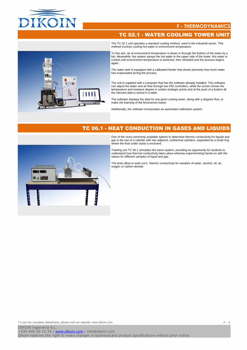
Logo-DK
F - THERMODYNAMICS
The TC 02.1 unit operates a standard cooling method, used in the industrial sector. This method involves cooling hot water to environment temperature.
To this aim, air at environment temperature is blown in through the bottom of the tower by a fan. Meanwhile, the system sprays the hot water in the upper side of the tower, this water is cooled until environment temperature is achieved, then reheated and the process begins again.
The water tank is equipped with a calibrated feeder that shows precisely how much water has evaporaded during the process.
The unit is supplied with a computer that has the software already installed. This software can adjust the water and air flow through two PID controllers, while the screen shows the temperature and moisture degree in certain strategic points and at the push of a buttom all the relevant data is stored in a table.
The software displays the data for any given cooling tower, along with a diagram flow, to make the learning of the fenomenon easier.
Additionally, the software incorporates an automated calibration system.
TC 02.1 - WATER COOLING TOWER UNIT
One of the most commonly available sytems to determine thermic conductivity for liquids and gas is the use of a cylinder with two adjacent, isothermal cylinders, separated by a small ring where the fluid under study is enclosed.
Training unit TC 06.1 simulates the same system, providing an opportunity for students to understand how thermal conductivity takes place whereas experimenting hands-on with the values for different samples of liquid and gas.
The tests allow to work out k thermic conductivity for samples of water, alcohol, oil, air, oxygen or carbon dioxide.
TC 06.1 - HEAT CONDUCTION IN GASES AND LIQUIDS
To see the complete datasheets, please visit our website: www.dikoin.com
Catalogos-Pie19F - 2
DIKOIN Ingeniería S.L.+034 946 55 15 35 / www.dikoin.com / [email protected] reserves the right to make changes in technical and product specifications without prior notice.
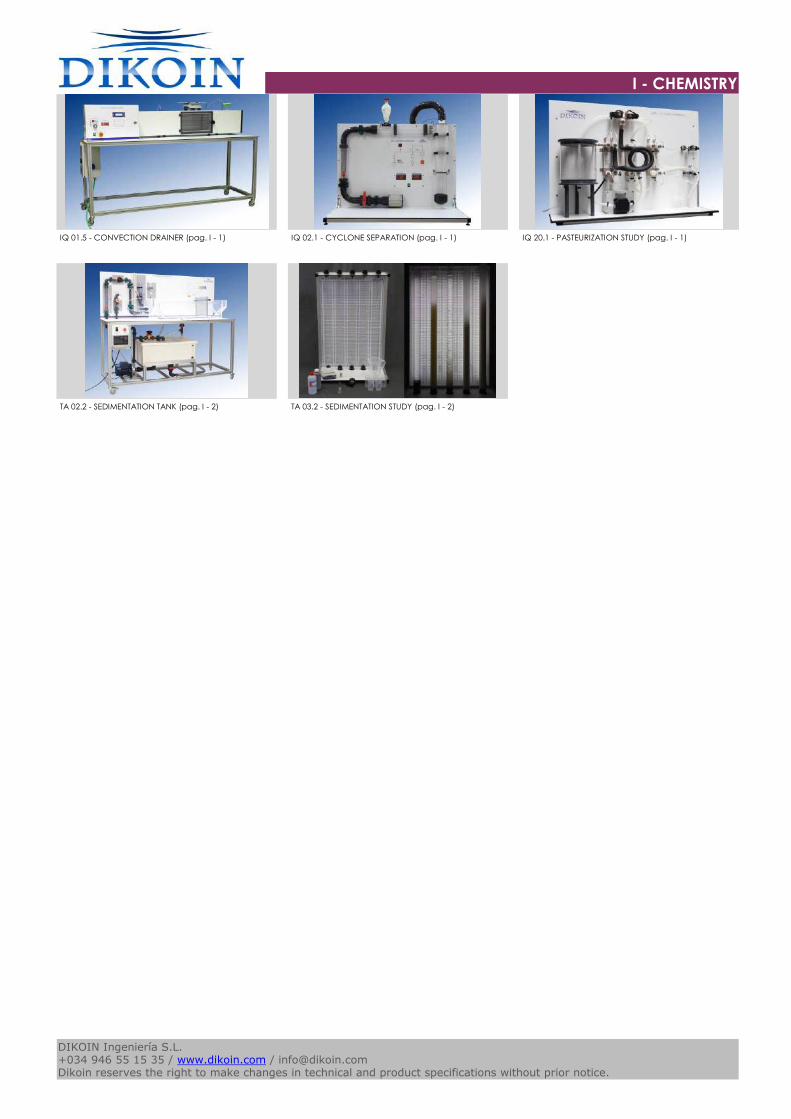
I - CHEMISTRY
Logo-DK
IQ 01.5 - CONVECTION DRAINER (pag. I - 1) IQ 02.1 - CYCLONE SEPARATION (pag. I - 1) IQ 20.1 - PASTEURIZATION STUDY (pag. I - 1)
TA 02.2 - SEDIMENTATION TANK (pag. I - 2) TA 03.2 - SEDIMENTATION STUDY (pag. I - 2)
Catalogos-Pie19DIKOIN Ingeniería S.L.+034 946 55 15 35 / www.dikoin.com / [email protected] reserves the right to make changes in technical and product specifications without prior notice.
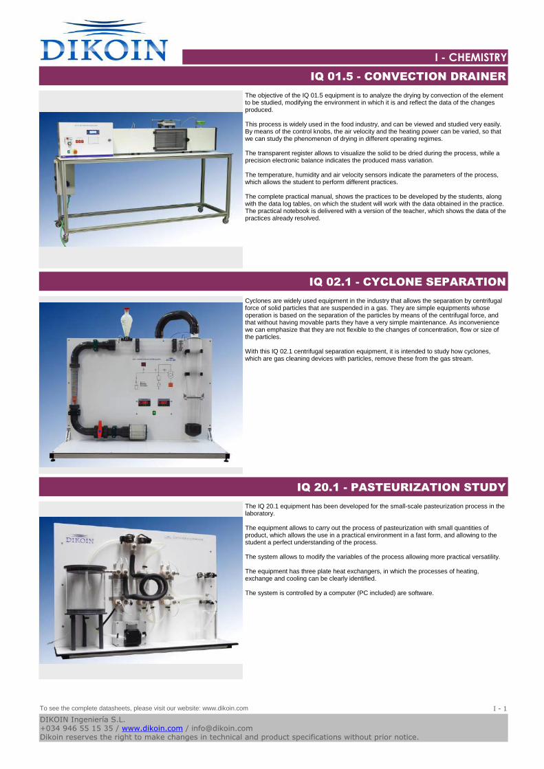
Logo-DK
I - CHEMISTRY
The objective of the IQ 01.5 equipment is to analyze the drying by convection of the element to be studied, modifying the environment in which it is and reflect the data of the changes produced.
This process is widely used in the food industry, and can be viewed and studied very easily. By means of the control knobs, the air velocity and the heating power can be varied, so that we can study the phenomenon of drying in different operating regimes.
The transparent register allows to visualize the solid to be dried during the process, while a precision electronic balance indicates the produced mass variation.
The temperature, humidity and air velocity sensors indicate the parameters of the process, which allows the student to perform different practices.
The complete practical manual, shows the practices to be developed by the students, along with the data log tables, on which the student will work with the data obtained in the practice. The practical notebook is delivered with a version of the teacher, which shows the data of the practices already resolved.
IQ 01.5 - CONVECTION DRAINER
Cyclones are widely used equipment in the industry that allows the separation by centrifugal force of solid particles that are suspended in a gas. They are simple equipments whose operation is based on the separation of the particles by means of the centrifugal force, and that without having movable parts they have a very simple maintenance. As inconvenience we can emphasize that they are not flexible to the changes of concentration, flow or size of the particles.
With this IQ 02.1 centrifugal separation equipment, it is intended to study how cyclones, which are gas cleaning devices with particles, remove these from the gas stream.
IQ 02.1 - CYCLONE SEPARATION
The IQ 20.1 equipment has been developed for the small-scale pasteurization process in the laboratory.
The equipment allows to carry out the process of pasteurization with small quantities of product, which allows the use in a practical environment in a fast form, and allowing to the student a perfect understanding of the process.
The system allows to modify the variables of the process allowing more practical versatility.
The equipment has three plate heat exchangers, in which the processes of heating, exchange and cooling can be clearly identified.
The system is controlled by a computer (PC included) are software.
IQ 20.1 - PASTEURIZATION STUDY
To see the complete datasheets, please visit our website: www.dikoin.com
Catalogos-Pie19I - 1
DIKOIN Ingeniería S.L.+034 946 55 15 35 / www.dikoin.com / [email protected] reserves the right to make changes in technical and product specifications without prior notice.
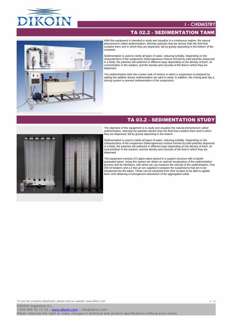
Logo-DK
I - CHEMISTRY
With this equipment is intended to study and visualize in a continuous regime, the natural phenomenon called sedimentation, whereby particles that are denser than the fluid that contains them and in which they are dispersed, fall by gravity depositing in the bottom of the container.
Sedimentation is used to clarify all types of water, reducing turbidity. Depending on the characteristics of the suspension (heterogeneous mixture formed by solid particles dispersed in a fluid), the particles will sediment in different ways depending on the density of them, its concentration in the solution, and the density and viscosity of the fluid in which they are dispersed.
The sedimentation tank has a lower tank of mixture in which a suspension is prepared by adding the additive whose sedimentation we want to study. In addition, the mixing tank has a stirring system to prevent sedimentation of the suspension.
TA 02.2 - SEDIMENTATION TANK
The objective of this equipment is to study and visualize the natural phenomenon called sedimentation, whereby the particles denser than the fluid that contains them and in which they are dispersed, fall by gravity depositing in the bottom.
Sedimentation is used to clarify all types of water, reducing turbidity. Depending on the characteristics of the suspension (heterogeneous mixture formed by solid particles dispersed in a fluid), the particles will sediment in different ways depending on the density of them, its concentration in the solution, and the density and viscosity of the fluid in which they are dispersed.
The equipment consists of 5 glass tubes placed in a support structure with a backlit graduated panel. Using this system we obtain an optimal visualization of the sedimentation process and its interfaces, with which we can measure the velocity of the sedimentation. Five 250 ml beakers and a 2 liter jar are supplied to prepare the suspensions that are to be introduced into the tubes. These can be extracted from their location to be able to agitate them until obtaining a homogenous dissolution of the aggregated solids.
TA 03.2 - SEDIMENTATION STUDY
To see the complete datasheets, please visit our website: www.dikoin.com
Catalogos-Pie19I - 2
DIKOIN Ingeniería S.L.+034 946 55 15 35 / www.dikoin.com / [email protected] reserves the right to make changes in technical and product specifications without prior notice.
K - MECHANICS
Logo-DK
ST 01.1 - MOUNTING FRAME FOR FLAT STRUCTURES (pag.
K - 1)
ST 01.2 - FRAME STUDY (pag. K - 1) ST 03.1 - CONTINUOUS BEAMS (pag. K - 1)
ST.Z.01 - WEIGHT SYSTEM FOR ST SERIES (pag. K - 2) ST.Z.02 - DISPLACEMENT MEASUREMENT SYSTEM FOR ST
SERIES (pag. K - 2)
Catalogos-Pie19DIKOIN Ingeniería S.L.+034 946 55 15 35 / www.dikoin.com / [email protected] reserves the right to make changes in technical and product specifications without prior notice.
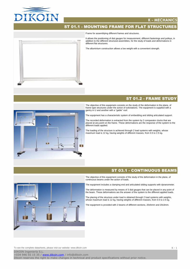
Logo-DK
K - MECHANICS
Frame for assemblying different frames and structures.
It allows the positioning of dial gauges for measurement, different fastenings and pulleys, in addition to the different structural assemblies, for the study of loads and deformations in different flat structures.
The alluminium construction allows a low weight with a convenient strength.
ST 01.1 - MOUNTING FRAME FOR FLAT STRUCTURES
The objective of this equipmetn consists on the study of the deformation in the plane, of frame type structures under the action of solicitations. The equipment is supplied with a gantry in U and another with a "gable" roof.
The equipment has a characteristic system of embedding and sliding articulated support.
The recorded deformation is extracted from the system by 2 comparator clocks that are placed at any point on the frame. These deformations are the response of the system to the different loads applied.
The loading of the structure is achieved through 2 load systems with weights, whose maximum load is 12 kg, having weights of different masses, from 0.5 to 2.5 kg.
ST 01.2 - FRAME STUDY
The objective of this equipment consists of the study of the deformation in the plane, of continuous beams under the action of loads.
The equipment includes a clamping end and articulated sliding supports with dynanometer.
The deformation is measured by means of 3 dial gauges that can be placed in any point of the beam. These deformations are the answer of the system to the different applied loads.
The placing of the structure under load is obtained through 2 load systems with weights, whose maximum load is 12 kg, having weights of different masses, from 0.5 to 2.5 kg.
The equipment is provided with 2 beams of different sections, 20x5mm and 20x3mm.
ST 03.1 - CONTINUOUS BEAMS
To see the complete datasheets, please visit our website: www.dikoin.com
Catalogos-Pie19K - 1
DIKOIN Ingeniería S.L.+034 946 55 15 35 / www.dikoin.com / [email protected] reserves the right to make changes in technical and product specifications without prior notice.
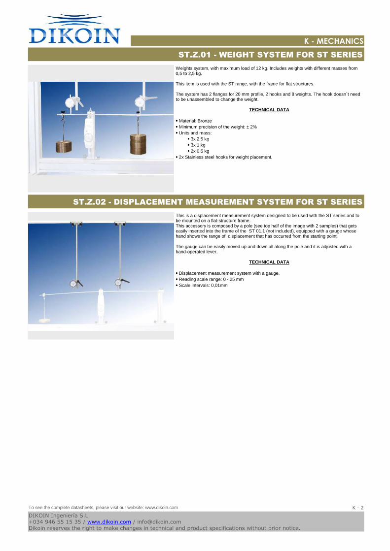
Logo-DK
K - MECHANICS
Weights system, with maximum load of 12 kg. Includes weights with different masses from 0,5 to 2,5 kg.
This item is used with the ST range, with the frame for flat structures.
The system has 2 flanges for 20 mm profile, 2 hooks and 8 weights. The hook doesn`t need to be unassembled to change the weight.
TECHNICAL DATA
⦁ Material: Bronze
⦁ Minimum precision of the weight: ± 2%
⦁ Units and mass:
⦁ 3x 2.5 kg
⦁ 3x 1 kg
⦁ 2x 0.5 kg
⦁ 2x Stainless steel hooks for weight placement.
ST.Z.01 - WEIGHT SYSTEM FOR ST SERIES
This is a displacement measurement system designed to be used with the ST series and to be mounted on a flat-structure frame. This accessory is composed by a pole (see top half of the image with 2 samples) that gets easily inserted into the frame of the ST 01.1 (not included), equipped with a gauge whose hand shows the range of displacement that has occurred from the starting point.
The gauge can be easily moved up and down all along the pole and it is adjusted with a hand-operated lever.
TECHNICAL DATA
⦁ Displacement measurement system with a gauge.
⦁ Reading scale range: 0 - 25 mm
⦁ Scale intervals: 0,01mm
ST.Z.02 - DISPLACEMENT MEASUREMENT SYSTEM FOR ST SERIES
To see the complete datasheets, please visit our website: www.dikoin.com
Catalogos-Pie19K - 2
DIKOIN Ingeniería S.L.+034 946 55 15 35 / www.dikoin.com / [email protected] reserves the right to make changes in technical and product specifications without prior notice.
N - MAINTENANCE
Logo-DK
MM01 - MOUNTING KIT: BALL GRAPH AND CLOSING
VALVE (pag. N - 1)
MM02 - MOUNTING KIT: PLUNGER COMPRESSOR (pag.
N - 1)
MM03 - ASSEMBLY AND MAINTENANCE: CENTRIFUGAL
MULTI-STEEL PUMP (pag. N - 1)
MM04 - ASSEMBLY AND MAINTENANCE: SCREW PUMP
(pag. N - 2)
MM05 - ASSEMBLY AND MAINTENANCE: DIAPHRAGM
PUMP (pag. N - 2)
MM06 - ASSEMBLY AND MAINTENANCE: PLUNGER PUMP
(pag. N - 2)
MM07 - ASSEMBLY AND MAINTENANCE: GEAR PUMP
(pag. N - 3)
MM08 - MOUNTING KIT: HYDRODYNAMIC SLIDE
BEARING (pag. N - 3)
MM09 - MOUNTING KIT: SHUT-OFF VALVE (pag. N - 3)
MM10 - MOUNTING KIT: COMBINED GEAR (pag. N - 4) MM11 - KIT GATE FLAT WEDGE FLAP AND TITLED SEAT
VALVE (pag. N - 4)
Catalogos-Pie19DIKOIN Ingeniería S.L.+034 946 55 15 35 / www.dikoin.com / [email protected] reserves the right to make changes in technical and product specifications without prior notice.
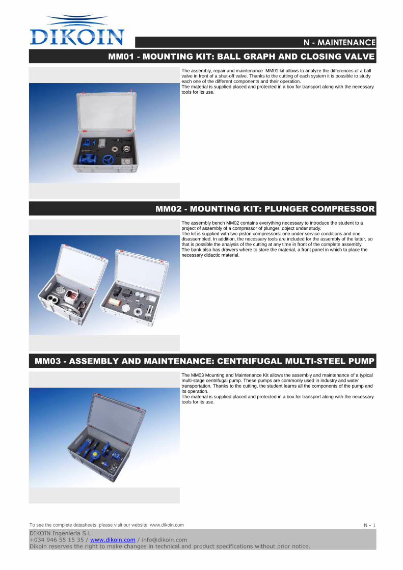
Logo-DK
N - MAINTENANCE
The assembly, repair and maintenance MM01 kit allows to analyze the differences of a ball valve in front of a shut-off valve. Thanks to the cutting of each system it is possible to study each one of the different components and their operation.The material is supplied placed and protected in a box for transport along with the necessary tools for its use.
MM01 - MOUNTING KIT: BALL GRAPH AND CLOSING VALVE
The assembly bench MM02 contains everything necessary to introduce the student to a project of assembly of a compressor of plunger, object under study.The kit is supplied with two piston compressors: one under service conditions and one disassembled. In addition, the necessary tools are included for the assembly of the latter, so that is possible the analysis of the cutting at any time in front of the complete assembly.The bank also has drawers where to store the material, a front panel in which to place the necessary didactic material.
MM02 - MOUNTING KIT: PLUNGER COMPRESSOR
The MM03 Mounting and Maintenance Kit allows the assembly and maintenance of a typical multi-stage centrifugal pump. These pumps are commonly used in industry and water transportation. Thanks to the cutting, the student learns all the components of the pump and its operation.The material is supplied placed and protected in a box for transport along with the necessary tools for its use.
MM03 - ASSEMBLY AND MAINTENANCE: CENTRIFUGAL MULTI-STEEL PUMP
To see the complete datasheets, please visit our website: www.dikoin.com
Catalogos-Pie19N - 1
DIKOIN Ingeniería S.L.+034 946 55 15 35 / www.dikoin.com / [email protected] reserves the right to make changes in technical and product specifications without prior notice.
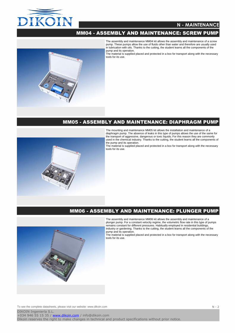
Logo-DK
N - MAINTENANCE
The assembly and maintenance MM04 kit allows the assembly and maintenance of a screw pump. These pumps allow the use of fluids other than water and therefore are usually used in lubrication with oils. Thanks to the cutting, the student learns all the components of the pump and its operation.The material is supplied placed and protected in a box for transport along with the necessary tools for its use.
MM04 - ASSEMBLY AND MAINTENANCE: SCREW PUMP
The mounting and maintenance MM05 kit allows the installation and maintenance of a diaphragm pump. The absence of leaks in this type of pumps allows the use of the same for the transport of aggressive, dangerous or toxic liquids; For this reason they are commonly used in the chemical industry. Thanks to the cutting, the student learns all the components of the pump and its operation.The material is supplied placed and protected in a box for transport along with the necessary tools for its use.
MM05 - ASSEMBLY AND MAINTENANCE: DIAPHRAGM PUMP
The assembly and maintenance MM06 kit allows the assembly and maintenance of a plunger pump. For a constant velocity regime, the volumetric flow rate in this type of pumps remains constant for different pressures. Habitually employed in residential buildings, industry or gardening. Thanks to the cutting, the student learns all the components of the pump and its operation.The material is supplied placed and protected in a box for transport along with the necessary tools for its use.
MM06 - ASSEMBLY AND MAINTENANCE: PLUNGER PUMP
To see the complete datasheets, please visit our website: www.dikoin.com
Catalogos-Pie19N - 2
DIKOIN Ingeniería S.L.+034 946 55 15 35 / www.dikoin.com / [email protected] reserves the right to make changes in technical and product specifications without prior notice.
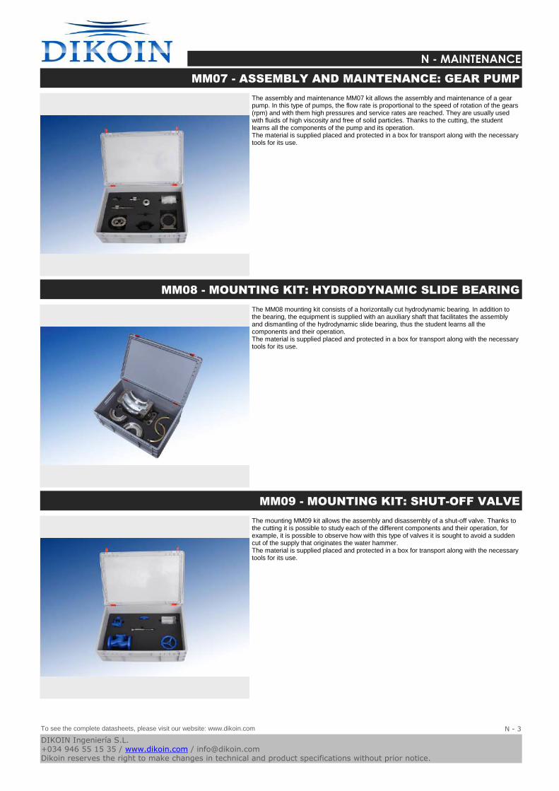
Logo-DK
N - MAINTENANCE
The assembly and maintenance MM07 kit allows the assembly and maintenance of a gear pump. In this type of pumps, the flow rate is proportional to the speed of rotation of the gears (rpm) and with them high pressures and service rates are reached. They are usually used with fluids of high viscosity and free of solid particles. Thanks to the cutting, the student learns all the components of the pump and its operation.The material is supplied placed and protected in a box for transport along with the necessary tools for its use.
MM07 - ASSEMBLY AND MAINTENANCE: GEAR PUMP
The MM08 mounting kit consists of a horizontally cut hydrodynamic bearing. In addition to the bearing, the equipment is supplied with an auxiliary shaft that facilitates the assembly and dismantling of the hydrodynamic slide bearing, thus the student learns all the components and their operation.The material is supplied placed and protected in a box for transport along with the necessary tools for its use.
MM08 - MOUNTING KIT: HYDRODYNAMIC SLIDE BEARING
The mounting MM09 kit allows the assembly and disassembly of a shut-off valve. Thanks to the cutting it is possible to study each of the different components and their operation, for example, it is possible to observe how with this type of valves it is sought to avoid a sudden cut of the supply that originates the water hammer.The material is supplied placed and protected in a box for transport along with the necessary tools for its use.
MM09 - MOUNTING KIT: SHUT-OFF VALVE
To see the complete datasheets, please visit our website: www.dikoin.com
Catalogos-Pie19N - 3
DIKOIN Ingeniería S.L.+034 946 55 15 35 / www.dikoin.com / [email protected] reserves the right to make changes in technical and product specifications without prior notice.

Logo-DK
N - MAINTENANCE
The mounting MM10 kit contains all the necessary parts for the assembly of a combined gear. The complete transmission is formed by several transmissions through different types of gears and in which only a manual force intervenes.The material is supplied placed and protected in a box for transport along with the necessary tools for its use.
MM10 - MOUNTING KIT: COMBINED GEAR
The MM11 Mounting Kit allows the differences between a flat wedge flap and a tilted seat valve. Thanks to the cutting of each system it is possible to study each one of the different components and their operation.The material is supplied placed and protected in a box for transport along with the necessary tools for its use.
MM11 - KIT GATE FLAT WEDGE FLAP AND TITLED SEAT VALVE
To see the complete datasheets, please visit our website: www.dikoin.com
Catalogos-Pie19N - 4
DIKOIN Ingeniería S.L.+034 946 55 15 35 / www.dikoin.com / [email protected] reserves the right to make changes in technical and product specifications without prior notice.


![3. Standards and IEC61508 - Gladcs.gla.ac.uk/~johnson/teaching/safety/powerpoint/3_Standards.pdf · IEC 61508 (Definitions) • Equipment Under control (EUC) [3.2.3]: equipment, machinery,](https://img.pdfslide.net/doc/110x75/5ca47e7f88c993a3308bf4a6/3-standards-and-iec61508-johnsonteachingsafetypowerpoint3standardspdf.jpg)