Embed Size (px)
Citation preview
TECHNICAL TRENDS FOR LONG SPAN BRIDGE FOUNDATIONS
Steve Hencher Halcrow China Limited, Hong Kong Professor of Engineering Geology, the University of Leeds, United Kingdom
SYNOPSIS: The main trends for founding longer span bridges are inevitably greater loads with larger foundations
and consequently more piles, caissons or barrettes as necessary. In many cases the time for construction is critical and
errors in judgment of ground conditions, leading to changes in foundation details (depth of piles for example) can have
major consequences for the completion times for projects and claims for additional works and extensions of time. In this
paper it is argued that the concepts of foundation design have changed little over many years and could be improved.
Developments in large scale testing of bored piles have however allowed better insights into ground support.
Improvements to ground investigation techniques and methodologies have also developed significantly and should be
better used to prevent the problems that often blight even well-funded projects. The paper is illustrated with examples
taken from large span bridges world-wide including the Incheon 2nd Bridge. Key Words: Large-span bridges, foundations, ground investigation
1. INTRODUCTION Large span bridges include cable stay bridges and suspension bridges. Typically cable stay bridges are currently limited to about 1 km for the main span and suspension bridges to 2 km for the main span. Main examples are listed in Tables 1 & 2. Clearly as the length of span to be supported increases so does the load to be carried by the foundations. In the case of suspension bridges, the main cables also need to be anchored at each end of the bridge and these anchorages need careful design. The longer the bridge, generally the greater the anchor loads to be supported by the ground. This paper examines solutions that have been adopted for large span bridges to carry the loads and the technologies that have been developed to assist in their design and construction. Some details of foundations for some of these major bridges, mostly comprising bored piles, are given in Table 3.
Name Location Main span (m) Year opened
Akashi-Kaikyō Bridge Japan 1,991 1998
Xihoumen Bridge China 1,650 2009
Storebælt Bridge Denmark 1,624 1998
Runyang Bridge Yangtze River, China 1,490 2005
Humber Bridge
(longest from 1981 to 1998)
Kingston upon Hull, United Kingdom 1,410 1981
Jiangyin Suspension Bridge Yangtze River, China 1,385 1999
Tsing Ma Bridge
(the longest with road and rail traffic)
Tsing Yi-Ma Wan, Hong Kong 1,377 1997
Verrazano-Narrows Bridge
(The longest from 1964 to 1981)
New York City
(Brooklyn–Staten Island), USA
1,298 1964
Golden Gate Bridge
(The longest from 1937 to 1964)
San Francisco-Marin County,
CA, USA
1,280 1937
Table 1 List of longest suspension bridges in the world
Table 2 List of longest cable stay main spans in the world
Name Location Main Span (m) Year Completed
Sutong Bridge Nantong, China 1,088 2008
Stonecutters Bridge Hong Kong 1,018 2009
Tatara Bridge Japan 890 1999
Pont de Normandie France 856 1995
Incheon Bridge South Korea 800 2009
Third Nanjing Yangtze Bridge Nanjing, China 648 2005
Second Nanjing Yangtze Bridge Nanjing, China 628 2001
Baishazhou Bridge Wuhan, China 618 2000
Qingzhou Bridge Fuzhou, China 605 2001
Yangpu Bridge Shanghai, China 602 1993
Bandra-Worli Sea Link Mumbai, India 600 2009
Øresund Bridge Denmark to Sweden 490 1999
Busan – Geoje Fixed Link South Korea 475 2010
Table 3 Details of foundations for some long span bridges
Bridge Part Span
(m)
Foundation
Type
Foundation
Dimensions
Additional Details Ref.
Main Span 420 Bored
Concrete
Piles
2.5m x 110m long
piles with two
clusters of 38 piles
for each pylon.
Pilecap 56 x 28 x
7m
Slipcasting at pile
base to improve
stability. Steel
cofferdams used.
Auxiliary
Navigation
Channels
120 /
140 /
160
Bored
Concrete
Piles
2.5m diameter
piles
Kezhushan
CSB
332 Bored
Concrete
Piles
2.5-3.2m variable
diameter
4 dampers
(2000kN) on
intersection of beam
and pylon
Onshore
section
50 PHC Pipe
Pile
0.6m diameter
Donghai
(East Ocean)
Bridge
Approach
Viaducts
60/70 Steel Pipe
Piles
1.5m diameter x
18 to 25mm thick.
Length 60m. All
piles raked, max.
gradient 1:4.5
Twin circular
pilecaps - diameter
10/11m, 30cm
thick concrete
cofferdam
Presentation by
Shanghai municipal
engineering and
design institute
(SMEDI), 2006.
Dong Hai bridge
sea-crossing project
in Shanghai, China:
General concept -
design, construction
and durability.
Shao, C., Deng, Q.
& Yang, Z. 2006.
Donghai Bridge.
International
Conference on
Bridge Engineering,
Hong Kong 2006.
Stonecutters Main Span 1018 End bearing
in-situ bored
piles
70-100m long
piles
45x35x9m deep
cofferdams
8m deep pilecap
cast in 1m lifts
Most piles
constructed by
conventional
temporary fully
cased methods.
However, west
tower located over
fault line so pile
location and pilecap
Tapley, M.J., West,
B.W., Yamamoto, S.
& Sham, R. 2006.
Challenges in
construction of
Stonecutters Bridge
and progress update.
International
Conference on
Bridge Part Span
(m)
Foundation
Type
Foundation
Dimensions
Additional Details Ref.
modified as
necessary with
telescopic casings
for deeper piles,
some of which were
sacrificed.
Rock sockets
reverse circular drill
with expanding bit
used.
Bridge Engineering,
Hong Kong 2006.
Approach
Bridges
140 Precast
Concrete
Caissons
Wall thickness
500mm to 800mm.
Base slabs 18m x
20m to 20m x 24m
Oresund
High
Bridge
490 Precast
Concrete
Caissons
Anchor Piers: 22m
x 24m
Pylon piers: 35m x
37.2m
Post tensioned in
bottom slab, ribs,
walls and top slab.
Dominant load case
is ship impact.
Gimsing et al. 2000.
The Bridge, The
Oresund Technical
Publications,
Oresundsbro
Konsortiet, 285p.
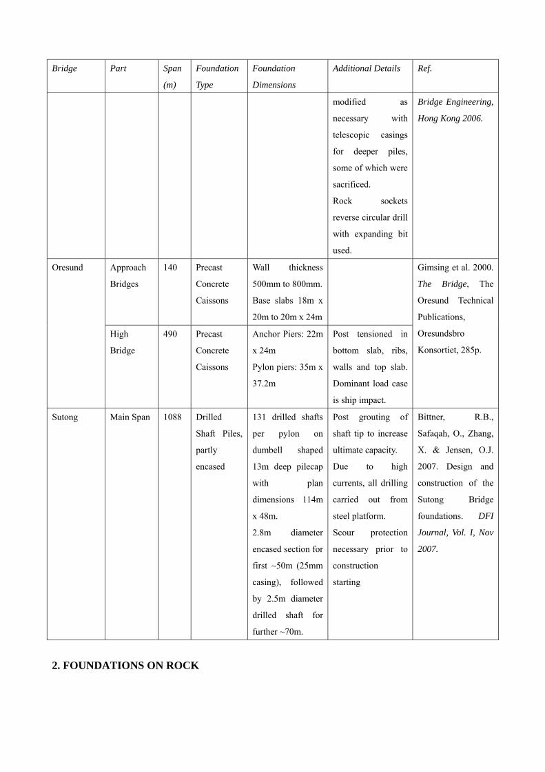
Sutong Main Span 1088 Drilled
Shaft Piles,
partly
encased
131 drilled shafts
per pylon on
dumbell shaped
13m deep pilecap
with plan
dimensions 114m
x 48m.
2.8m diameter
encased section for
first ~50m (25mm
casing), followed
by 2.5m diameter
drilled shaft for
further ~70m.
Post grouting of
shaft tip to increase
ultimate capacity.
Due to high
currents, all drilling
carried out from
steel platform.
Scour protection
necessary prior to
construction
starting
Bittner, R.B.,
Safaqah, O., Zhang,
X. & Jensen, O.J.
2007. Design and
construction of the
Sutong Bridge
foundations. DFI
Journal, Vol. I, Nov
2007.
2. FOUNDATIONS ON ROCK
As in any foundation design, the first preference would be to found directly on solid rock above water. This has the advantage that the design is simple; the rock can be cleaned off, mapped, assumptions checked and construction achieved within a clearly defined programme. That said, all these operations need to be carried out diligently, otherwise there may be disastrous consequences as has occurred recently at some construction projects. Foundations like these were used in Hong Kong for the outer piers and abutments of the Ting Kau cable stay bridge albeit with the use of cofferdams and some minor underwater concreting. Concrete foundations directly on rock were also used for the Tsing Yi end pier of the Tsing Ma suspension bridge - still the longest combined road and rail bridge in the world. The north tower of the Humber Bridge, UK, was similarly founded directly onto rock (chalk) whereas the southern tower was constructed on caissons, sunk with the help of superimposed steel ingots down to Jurassic mudrock (Simm, 1984). Where a pier or tower is to be founded offshore but on relatively good rock at shallow depth then large caissons can be constructed on-shore (or on a barge for Tsing Ma Bridge) and then floated out and sunk onto carefully prepared rock platforms, where the overlying sediments and other unsuitable materials have been removed. In the case of the Ma Wan tower foundation for the Tsing Ma bridge the preparation of the sockets to receive the caissons was carried out by up to 50 divers working in visibilities of only 150mm and mainly working by touch over seven-day weeks for two months (HK Highways Department, Tsing Ma Bridge, HK Govt. Publication). Floated and sunk, pre-formed caissons were also used to support the towers for the Akashi Kaikyo Ôhashi Bridge which has a main span of 1,991m and is the longest suspension bridge in the world: one and a half times as long as the Humber Bridge in the UK which held the same record from 1981 to 1998. Both of the 283m main towers are built on reinforced concrete caissons set underwater, each 80 m in diameter. The ground (mainly alluvium and other unsuitable unlithified sediments) below the Akashi Strait was dredged to a depth of 60 m to accommodate the caissons, which have to support 120,000 tonnes.
3. DEEP FOUNDATION As can be seen in Table 3, foundations for many bridges need to be taken much deeper, using piles generally, because the near surface materials are weak or compressible. This comes as no surprise because typically bridges are across rivers or at the coast where the geomorphological setting is such that weaker rock might be more likely to occur because faults or other zones of weak rock have been preferentially eroded. It might be pointed out here that buried river landscapes and estuaries are often associated with buried channels, filled with sediment that relate to conditions when the sea level was maybe 100 m lower than it is today, only 20 thousand years ago. Such channels are to be anticipated and searched for and should never be looked on as unexpected (Pirazzoli, 1996). Generally, providing proper methodologies of ground investigation are followed with desk study followed by staged, intelligent ground investigation than the major hazards will be identified and the engineers can get down to the real "nitty-gritty" of determining parameters to support the loading from the bridge. For Incheon 2nd Crossing, the GI was perfectly adequate and fit for purpose and demonstrated realistic geological models that met expectations. World record loading tests on sacrificial piles using Osterberg cells were then used to
prove the design parameters. In the event piles were constructed very closely to the design levels and all checks showed that the piles as-constructed met the requirements of the project. This project was carried out in what might however be called a "forgiving" site; the geology was not complex and the geotechnical conditions reasonably straightforward. Sometimes situations are more complex.
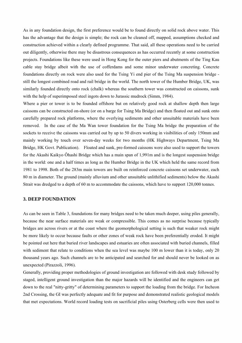
Figure 1 Electro-magnetic map of part of Hong Kong with major linear anomaly pointing towards
eastern end of Stonecutters Bridge.
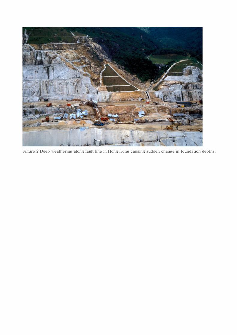
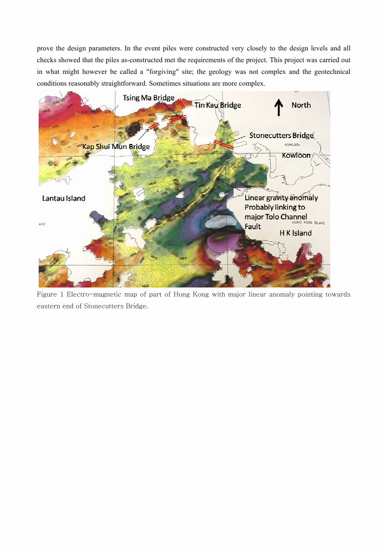
Figure 2 Deep weathering along fault line in Hong Kong causing sudden change in foundation depths.
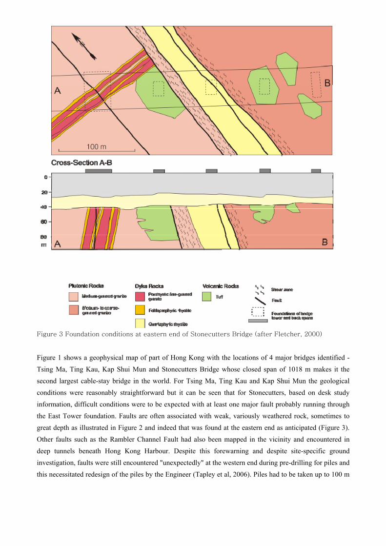
Figure 3 Foundation conditions at eastern end of Stonecutters Bridge (after Fletcher, 2000)
Figure 1 shows a geophysical map of part of Hong Kong with the locations of 4 major bridges identified - Tsing Ma, Ting Kau, Kap Shui Mun and Stonecutters Bridge whose closed span of 1018 m makes it the second largest cable-stay bridge in the world. For Tsing Ma, Ting Kau and Kap Shui Mun the geological conditions were reasonably straightforward but it can be seen that for Stonecutters, based on desk study information, difficult conditions were to be expected with at least one major fault probably running through the East Tower foundation. Faults are often associated with weak, variously weathered rock, sometimes to great depth as illustrated in Figure 2 and indeed that was found at the eastern end as anticipated (Figure 3). Other faults such as the Rambler Channel Fault had also been mapped in the vicinity and encountered in deep tunnels beneath Hong Kong Harbour. Despite this forewarning and despite site-specific ground investigation, faults were still encountered "unexpectedly" at the western end during pre-drilling for piles and this necessitated redesign of the piles by the Engineer (Tapley et al, 2006). Piles had to be taken up to 100 m
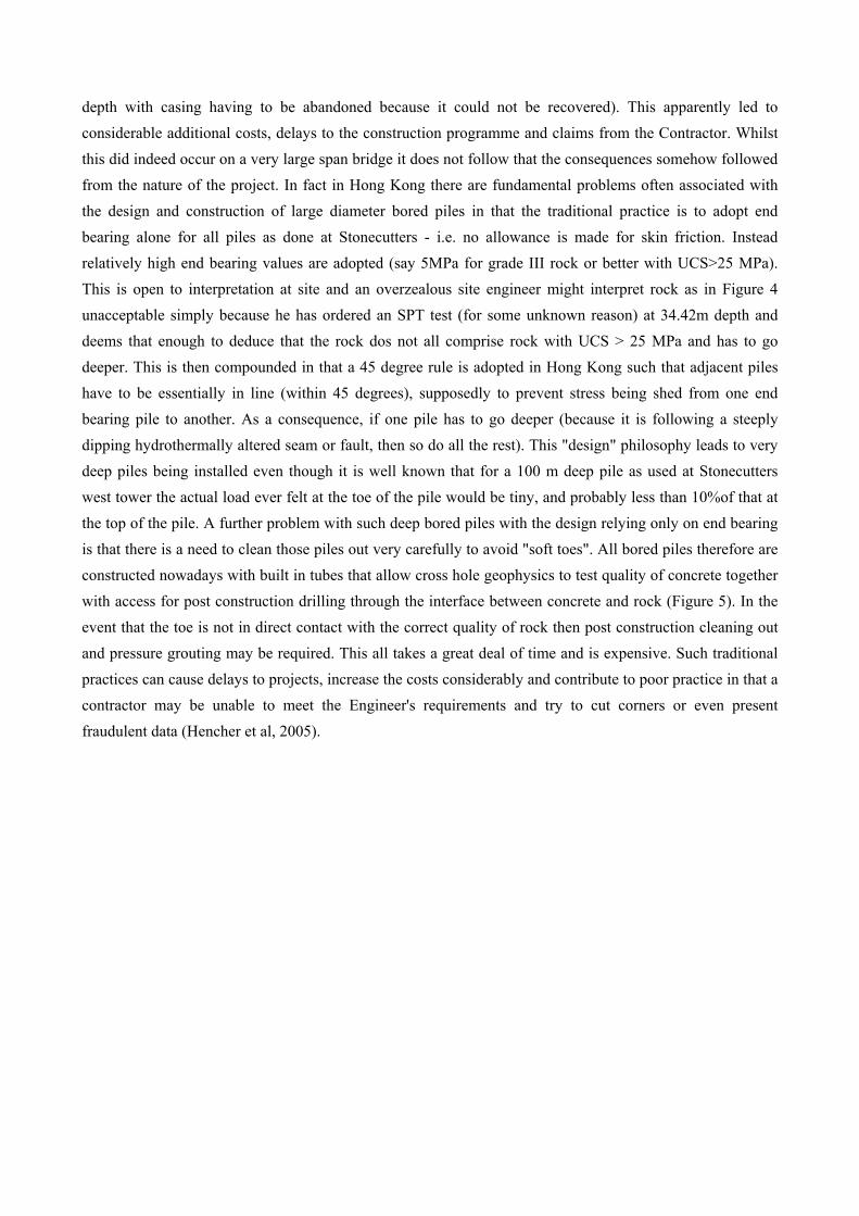
depth with casing having to be abandoned because it could not be recovered). This apparently led to considerable additional costs, delays to the construction programme and claims from the Contractor. Whilst this did indeed occur on a very large span bridge it does not follow that the consequences somehow followed from the nature of the project. In fact in Hong Kong there are fundamental problems often associated with the design and construction of large diameter bored piles in that the traditional practice is to adopt end bearing alone for all piles as done at Stonecutters - i.e. no allowance is made for skin friction. Instead relatively high end bearing values are adopted (say 5MPa for grade III rock or better with UCS>25 MPa). This is open to interpretation at site and an overzealous site engineer might interpret rock as in Figure 4 unacceptable simply because he has ordered an SPT test (for some unknown reason) at 34.42m depth and deems that enough to deduce that the rock dos not all comprise rock with UCS > 25 MPa and has to go deeper. This is then compounded in that a 45 degree rule is adopted in Hong Kong such that adjacent piles have to be essentially in line (within 45 degrees), supposedly to prevent stress being shed from one end bearing pile to another. As a consequence, if one pile has to go deeper (because it is following a steeply dipping hydrothermally altered seam or fault, then so do all the rest). This "design" philosophy leads to very deep piles being installed even though it is well known that for a 100 m deep pile as used at Stonecutters west tower the actual load ever felt at the toe of the pile would be tiny, and probably less than 10%of that at the top of the pile. A further problem with such deep bored piles with the design relying only on end bearing is that there is a need to clean those piles out very carefully to avoid "soft toes". All bored piles therefore are constructed nowadays with built in tubes that allow cross hole geophysics to test quality of concrete together with access for post construction drilling through the interface between concrete and rock (Figure 5). In the event that the toe is not in direct contact with the correct quality of rock then post construction cleaning out and pressure grouting may be required. This all takes a great deal of time and is expensive. Such traditional practices can cause delays to projects, increase the costs considerably and contribute to poor practice in that a contractor may be unable to meet the Engineer's requirements and try to cut corners or even present fraudulent data (Hencher et al, 2005).
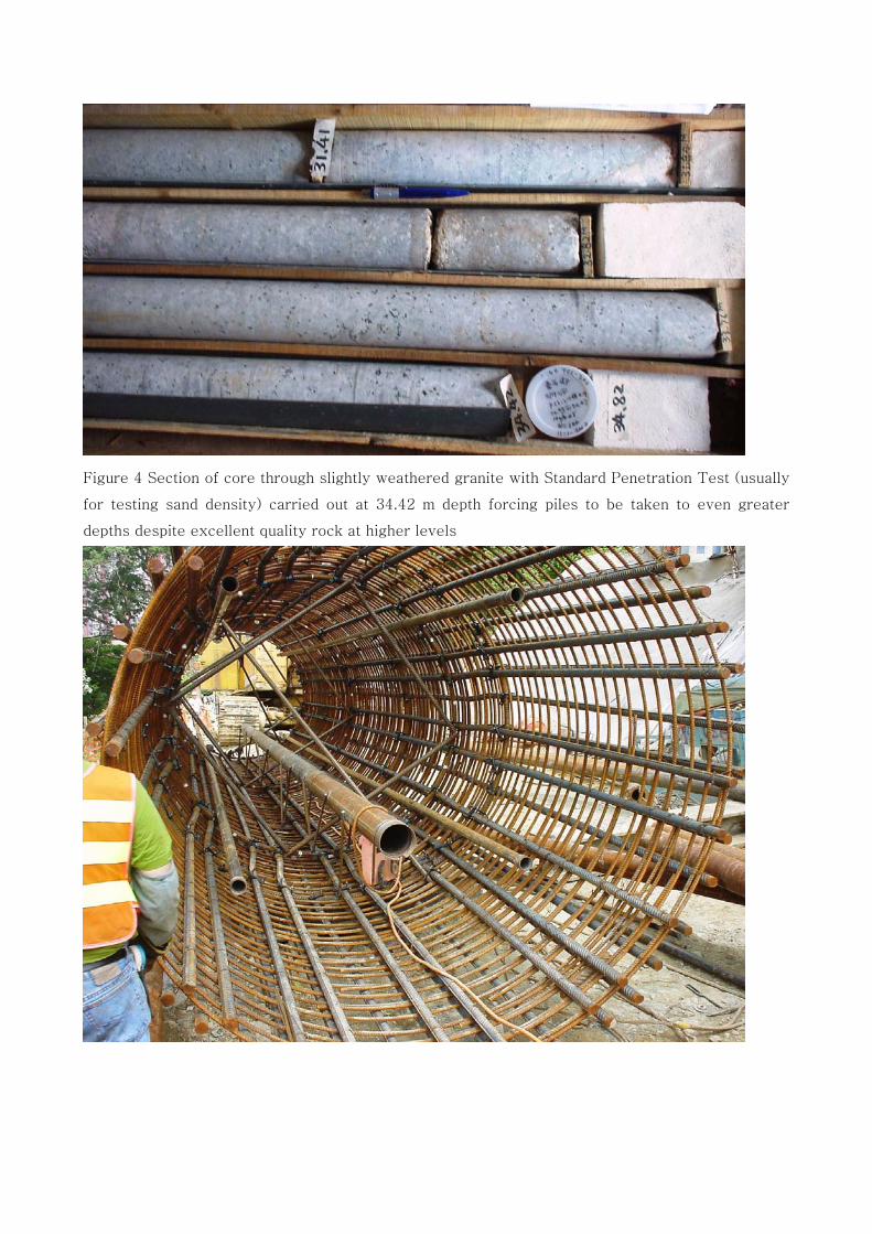
Figure 4 Section of core through slightly weathered granite with Standard Penetration Test (usually
for testing sand density) carried out at 34.42 m depth forcing piles to be taken to even greater
depths despite excellent quality rock at higher levels
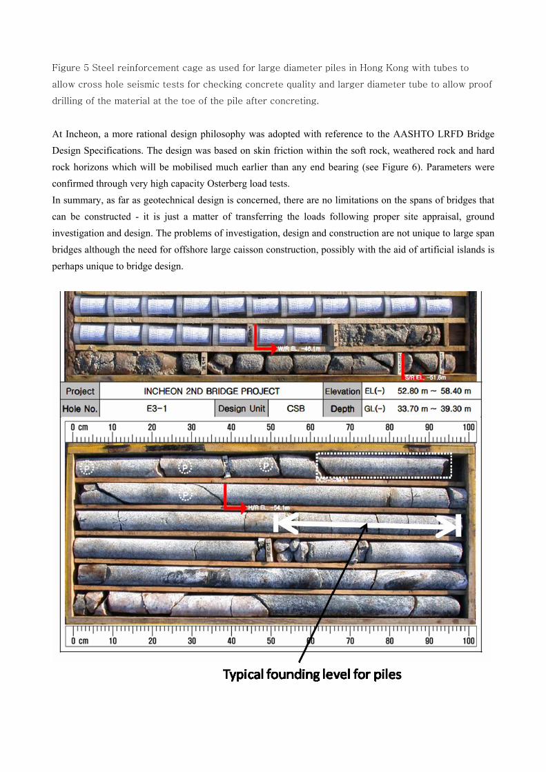
Figure 5 Steel reinforcement cage as used for large diameter piles in Hong Kong with tubes to
allow cross hole seismic tests for checking concrete quality and larger diameter tube to allow proof
drilling of the material at the toe of the pile after concreting.
At Incheon, a more rational design philosophy was adopted with reference to the AASHTO LRFD Bridge Design Specifications. The design was based on skin friction within the soft rock, weathered rock and hard rock horizons which will be mobilised much earlier than any end bearing (see Figure 6). Parameters were confirmed through very high capacity Osterberg load tests. In summary, as far as geotechnical design is concerned, there are no limitations on the spans of bridges that can be constructed - it is just a matter of transferring the loads following proper site appraisal, ground investigation and design. The problems of investigation, design and construction are not unique to large span bridges although the need for offshore large caisson construction, possibly with the aid of artificial islands is perhaps unique to bridge design.
Figure 6 Samples from Borehole E3-1 for Cable Stay Bridge Foundation E3
4. CONCLUSIONS The inevitable trend of longer span bridges being perceived, designed and constructed is that larger and larger loads are to be carried in the foundations and anchorages which provide challenges for geotechnical engineers. Despite these challenges our current level of understanding of engineering geology and geotechnics and the development of new sophisticated ground investigation techniques such as seismic tomography and down-hole logging technology, largely transferred from the oil and nuclear repository industries, means that foundation design should be essentially routine provided there is correct geological interpretation in the first place and proper procedures for investigation, modelling, checking and verification during construction. Unfortunately this is where many projects still go wrong despite the experience of many decades. The use of high capacity testing methods without the need for kentledge, as employed at Incheon, and consequently better understanding of the way that piles carry their loads should allow more economical yet safe design in the future.
References Bittner, R.B., Safaqah, O., Zhang, X. & Jensen, O.J. 2007. Design and construction of the Sutong Bridge foundations.
DFI Journal, Vol. I, Nov 2007. Fletcher, C.J.N. 2004. Geology of Site Investigation Boreholes from Hong Kong. AGC, Hong Kong, 132p. Gimsing et al. 2000. The Bridge, The Oresund Technical Publications, Oresundsbro Konsortiet, 285p. Hencher, S. R., Tyson, J. T. & Hutchinson, P. 2005. Investigating substandard piles in Hong Kong. Proceedings 3rd
International Conference on Forensic Engineering, Institution of Civil Engineers, London, 107-18. Pirazzoli, P.A. 1996. Sea-Level Changes. Wiley, 211p. Shanghai municipal engineering and design institute (SMEDI), 2006. Dong Hai bridge sea-crossing project in
Shanghai, China: General concept - design, construction and durability. Shao, C., Deng, Q. & Yang, Z. 2006. Donghai Bridge. International Conference on Bridge Engineering, Hong Kong
2006. Simm, K.F. 1984. Engineering solutions to geological problems in the design and construction of Humber Bridge.
Quarterly Journal of Engineering Geology, 17, 4, 301-06. Tapley, M.J., West, B.W., Yamamoto, S. & Sham, R. 2006. Challenges in construction of Stonecutters Bridge and
progress update. International Conference on Bridge Engineering, Hong Kong 2006.