Embed Size (px)
Citation preview
KATHREIN-Werke KG, Broadcast Antennas, P.O.Box 100 444, D-83004 Rosenheim, GermanyTelephone ( ++49 ) 8031-184 0, Telefax ( ++49 ) 8031-184 455, e-mail: [email protected]
www.kathrein.de
Technical
Documentation
UHF ISDB-T Antenna
TNU Montevideo
US Ch
30
75919516 ( 759190411KMB)
dated
25.02.2012
Technical
Documentation
UHF ISDB-T Antenna
TNU Montevideo
US Ch
30
75919516 ( 759190411KMB)
dated
25.02.2012

BCA/St2012-01-23 Page 1 of 3
Professional Broadcast Transmitting Antenna ________________________________________________________________
GENERAL DESCRIPTION AND MOUNTING INSTRUCTIONS
1. General
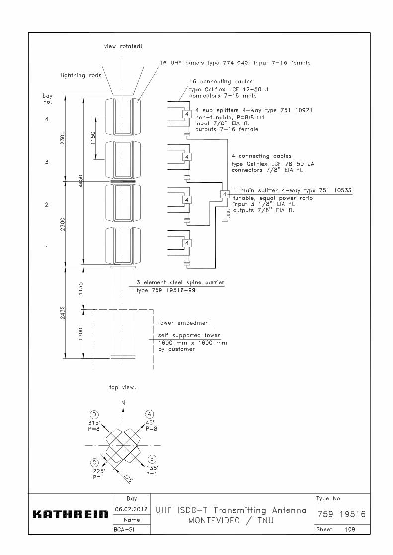
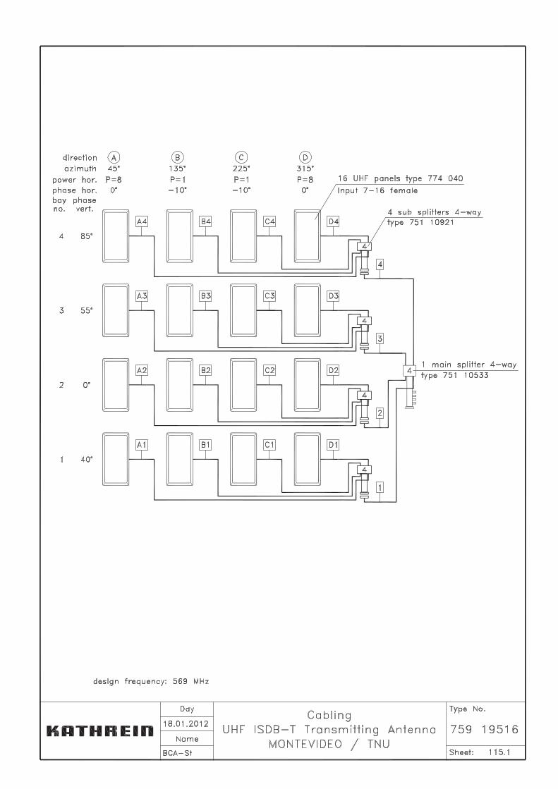
The transmitting antenna consists of antenna panels, which are arranged in several bays to certain azimuth directions. For details see sheet 109. Groups of panels are connected to subsplitters by cables. Subsplitters are connected to one (single feeder) or two mainsplitters (double feeder) by cables. For details on the cabling scheme see sheet 115.
� Before installation, refer to the enclosed antenna system documentation! � Check all the material for transport damages before mounting! � Always keep the connectors of panels, splitters and cables free of dirt, moisture or
water!� Take care that all components are adequately fixed and protected against falling down
or shaking in the wind! � For EIA flange connections, only use the thick O-rings supplied along with the cou-
pling element (inner bullet) and screw set! � Observe the local workplace safety instructions!
2. Mounting Instructions
2.1. Panels:
In principle, panels may be mounted to the steel carrier prior to (i.e. on ground) or after (i.e. on top) pulling the carrier. The carrier is not supplied by Kathrein. We recommend doing panel mounting on ground only if the carrier pulling process shows no danger of damaging the panel radomes by knocking against the tower. Panels shall be mechanically arranged as shown in sheet 109 of the antenna documenta-tion. At installation of panels the mark "top" is to be observed.
2.2. Connecting Cables:
The cables are to be connected as shown in sheet 115. Each cable is marked according to this scheme. Care must be taken that no O-Ring is missing and that the compression nuts (7-16 or 13-30) are tightened with an adequate tool. At the EIA flanges do not forget to apply the inner coupling element (bullet) and watch the correct fitting of the O-Rings. The cables should be laid in a way that they are protected against mechanical damage (not to put across edges!) Refer to the cable datasheet in the system documentation for allowed bending radius. Fixing of the cables shall be done by means of plastic straps 072 613 and 072 135.
BCA/St2012-01-23 Page 2 of 3
2.3. Power splitters:
The place for mounting the mainsplitters should be chosen in such a way that the feeder cable can be led to it vertically from below. Mainsplitters should be installed at the center of the antenna aperture. If there is too little space for the mainsplitters they can also be installed below the antenna. Subsplitters should be installed near the antenna panels so that all relevant panels can be connected by the branch cables. All splitters should be orientated vertically with the input facing downwards. For fixation you can use supplied steel frame or tension band clamps; for details see the technical drawings.In case of unequal power splitting, each output socket is marked with its corresponding power ratio. Refer to sheet 115 to connect the right cables and panels to the corresponding outputs. Our splitters are equipped with a ventilation tube, which must be closed for pressurized and opened for non-pressurized operation.
2.4. Main feeder cable:
Attention: Never turn the cable drum on its side!
It is recommended to mount the connector for the upper feeder end prior to pulling the cable. Follow the installation instructions included with the connectors. Protect the connector against water, dirt, moisture and mechanical damage during cable pulling.
For pulling the cable, use provided hoisting stockings, which shall be applied at a distance of max. 40 – 70 m. Equal load should be observed. Remove the hoisting stockings after pulling the first feeder and reuse them for the second feeder by using new cords type 072 678. Use special cable clamps for fixing the cable to the tower. Max. distance of the cable clamps depends on the feeder size and is given in the cable data sheet. It is important that the screws of the cable clamps are not overtightened in order to avoid deformation of the cable. Using a screwdriver is adequate. After clamping it is recommended to remove the hoisting stockings.
When connecting the cable to the mainsplitter watch the correct fitting of the O-Rings at the EIA flanges. Do not forget to apply the inner coupling element (bullet).
Earthing of the feeder cable shall be done by means of special earthing kits, at top and bottom and at the feed-through to the building.
In case of double feeder usage both feeders have to be measured and cut to equal electrical length.
Finally, do not forget to seal the connectors against water by pressing Plast2000 into the filling opening of the connector nut. Use the injection gun supplied. Refer to connector in-stallation instructions.
2012-01-23BCA/St
Page 3 of 3
2.5. Pressurization:
In case of pressurization the ventilation tubes of the power splitters have to be sealed with the sealing screw. For air-flow from main feeder to mainsplitter, a bore hole has to be drilled into the teflon-center-disc of the upper main feeder connector at the position marked.The gas stop point will be at the connectors of the connecting foam cables or at the panel.
The installation and commissioning of the dehydrator must be carried out according to the given instructions. The feeder cable can be connected to the dehydrator via air-hose and gas inlet, which should be part of the dehydrator delivery package. Fit the gas inlet to the connector head as per instructions!
Attention: Read the dehydrator manual and mind the instructions given on initialization run and regular maintenance (if necessary!).
2.6. Putting into operation:
We recommend performing a VSWR measurement of the antenna system before putting it into operation. The VSWR results may be optimized by tuning at the tuning section of the main splitter.
� For change of tuning, please proceed as follows: Remove the cover caps, remove the counter nuts and mark the original setting of the 4 tuning screws at the tuning section. Attention: Do not completely unscrew the tuning screws because there is danger of dropping these screws! By alternately turning the screws, the VSWR can be optimized to the operating channels. For this, a measuring instrument (e.g. Network Analyzer) can either be connected to the main splitter input or to the input of the feeder cable. After the tuning procedure, the screws must be secured by counter nuts and the covers must be tightly screwed together. Proper fitting of the sealing-rings must be observed.
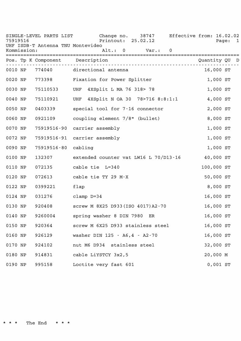
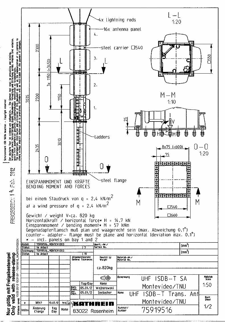
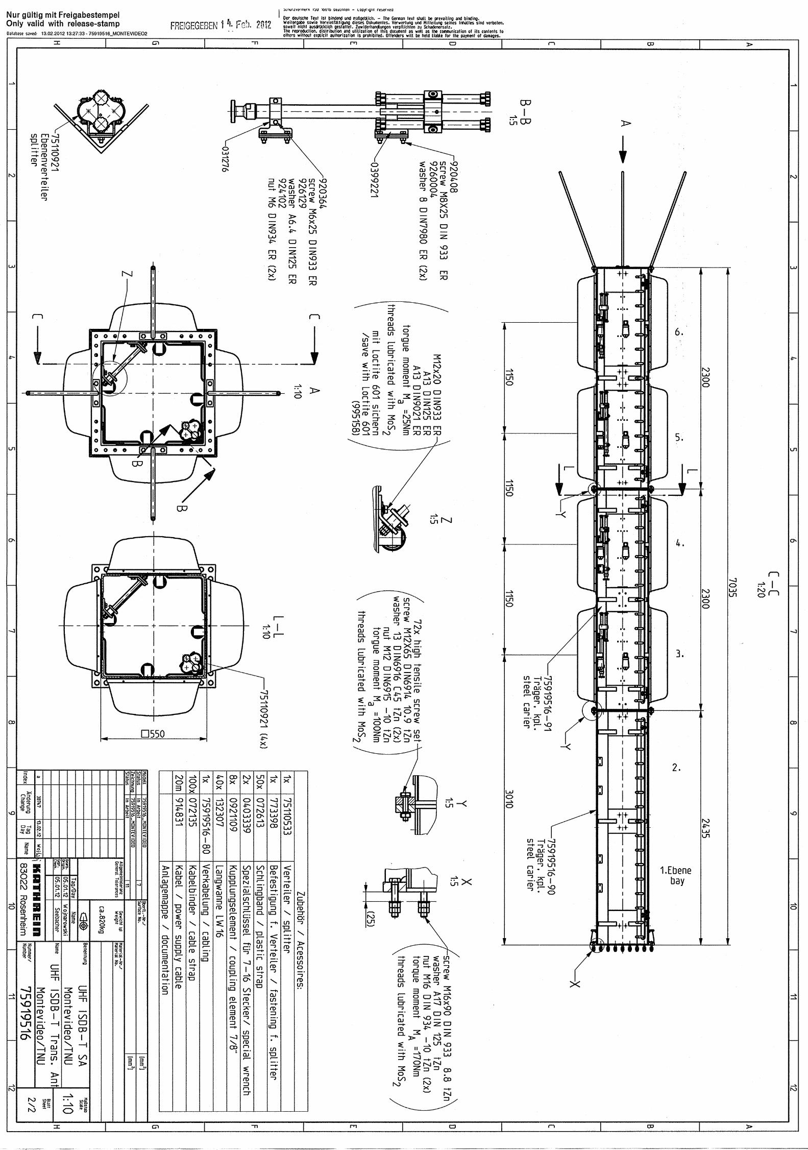
SINGLE-LEVEL PARTS LIST Change no. 38747 Effective from: 16.02.0275919516 Printout: 25.02.12 Page: 1UHF ISDB-T Antenna TNU MontevideoKommission: Alt.: Var.:0 0================================================================================Pos. Tp K Component Description Quantity QU D--------------------------------------------------------------------------------0010 NP 774040 directional antenna 16,000 ST
0020 NP 773398 Fixation for Power Splitter 1,000 ST
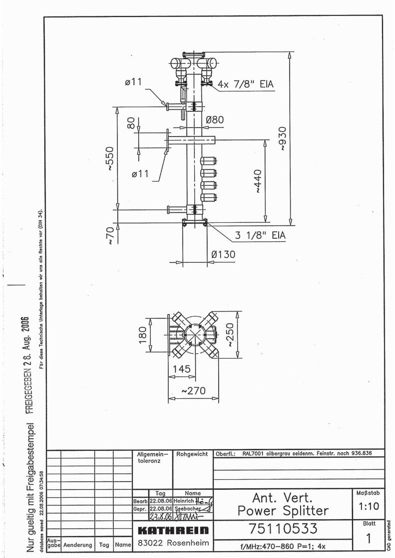
0030 NP 75110533 UHF 4XSplit L MA 76 318> 78 1,000 ST
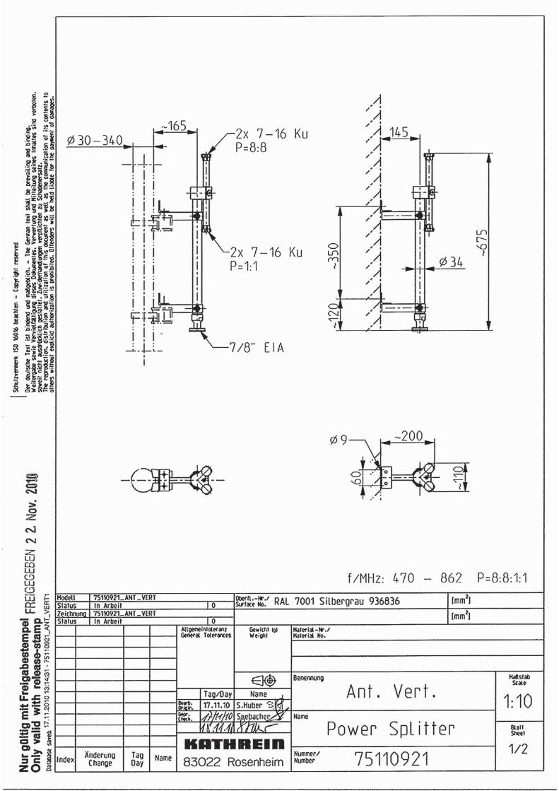
0040 NP 75110921 UHF 4XSplit N OA 30 78>716 8:8:1:1 4,000 ST
0050 NP 0403339 special tool for 7-16 connector 2,000 ST
0060 NP 0921109 coupling element 7/8" (bullet) 8,000 ST
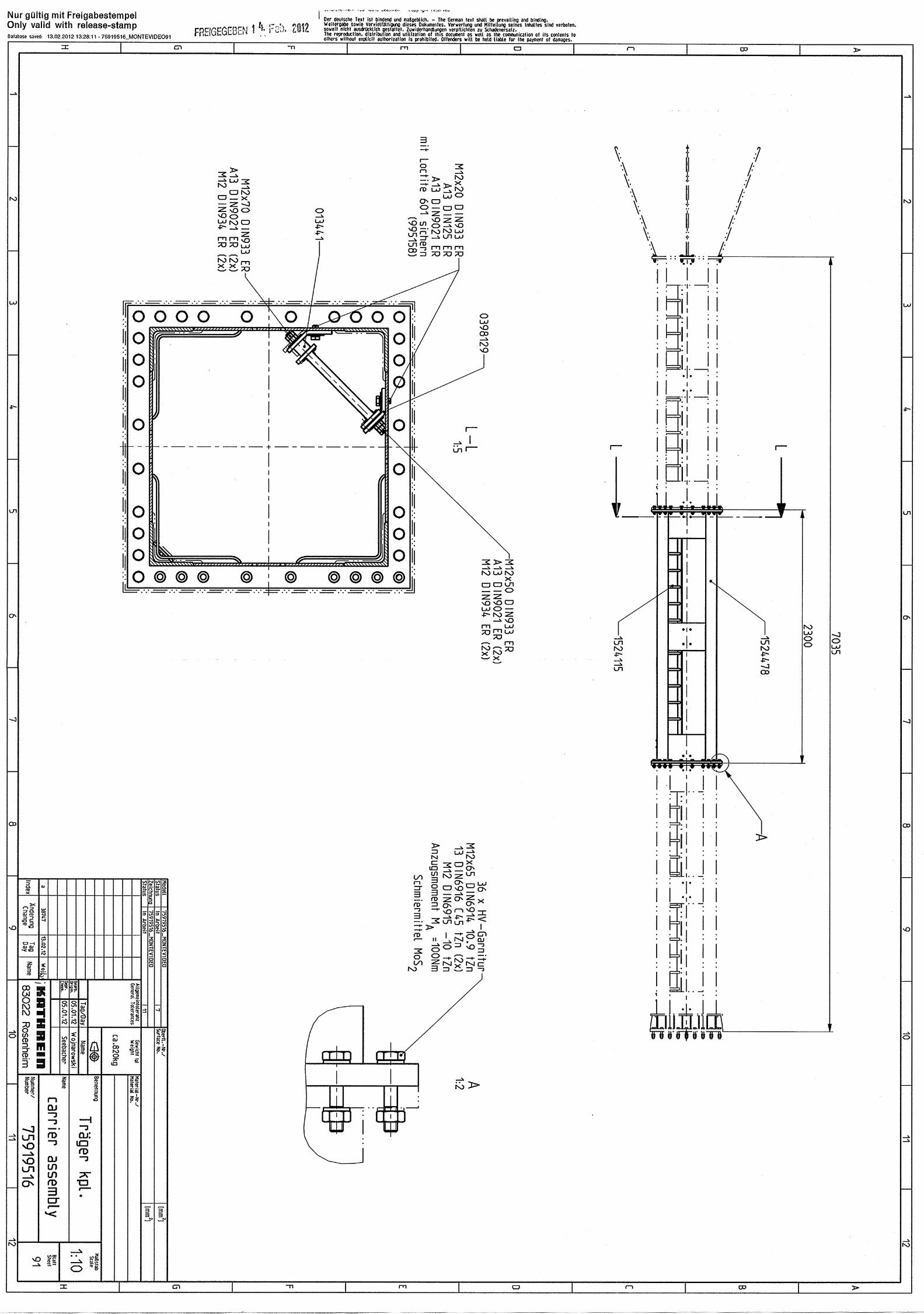
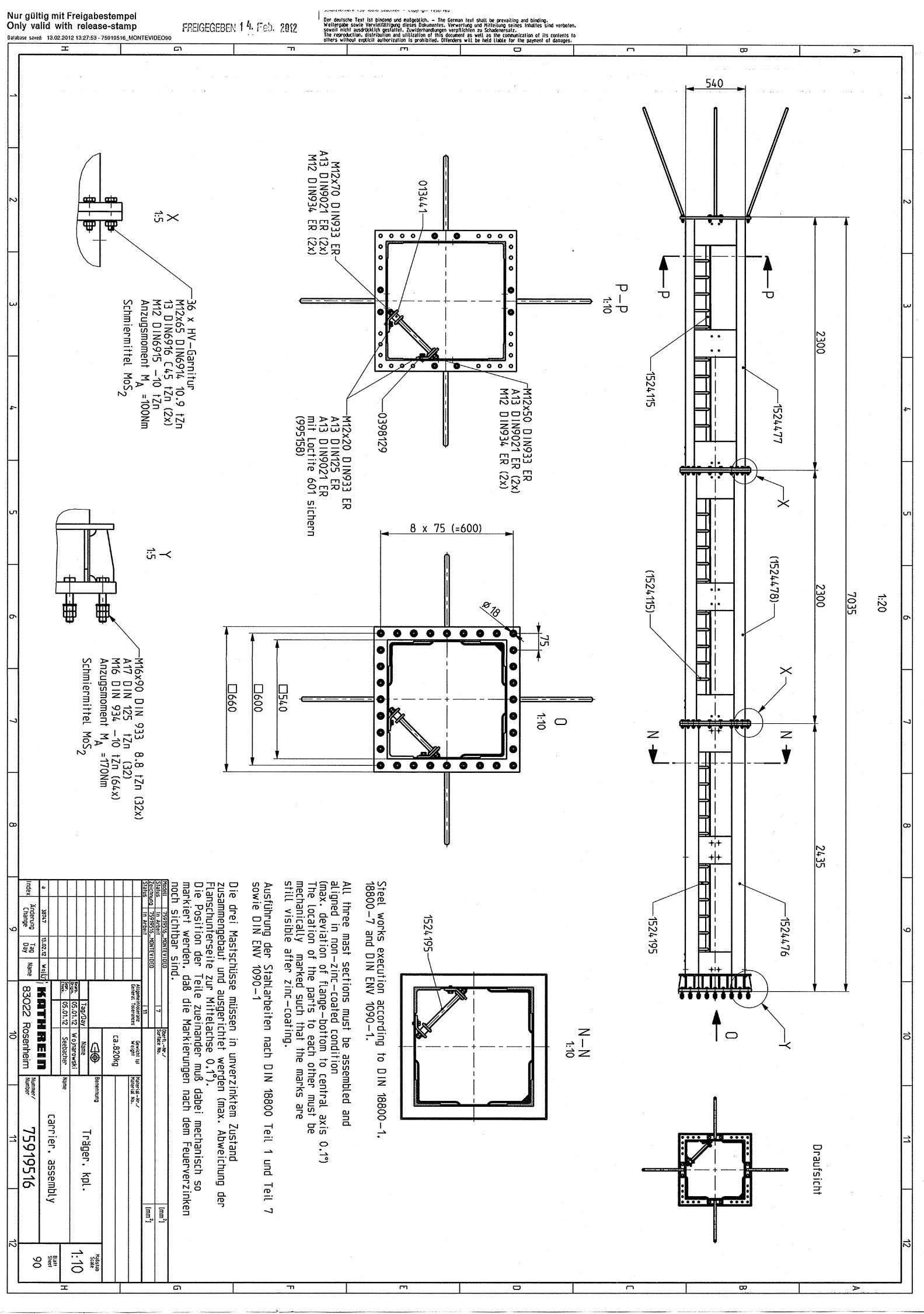
0070 NP 75919516-90 carrier assembly 1,000 ST
0072 NP 75919516-91 carrier assembly 1,000 ST
0090 NP 75919516-80 cabling 1,000 ST
0100 NP 132307 extended counter vat LW16 L 70/D13-16 40,000 ST
0110 NP 072135 cable tie L=340 100,000 ST
0120 NP 072613 cable tie TY 29 M-X 50,000 ST
0122 NP 0399221 flap 8,000 ST
0124 NP 031276 clamp D=34 16,000 ST
0130 NP 920408 screw M 8X25 D933(ISO 4017)A2-70 16,000 ST
0140 NP 9260004 spring washer 8 DIN 7980 ER 16,000 ST
0150 NP 920364 screw M 6X25 D933 stainless steel 16,000 ST
0160 NP 926129 washer DIN 125 - A6,4 - A2-70 16,000 ST
0170 NP 924102 nut M6 D934 stainless steel 32,000 ST
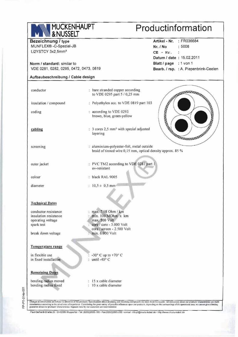
0180 NP 914831 cable LiYSTCY 3x2,5 20,000 M
0190 NP 995158 Loctite very fast 601 0,001 ST
* * * The End * * *
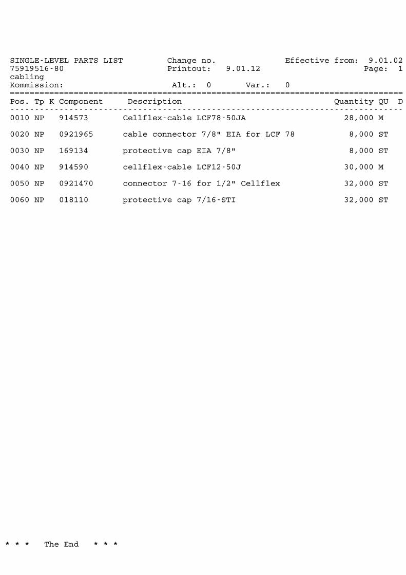
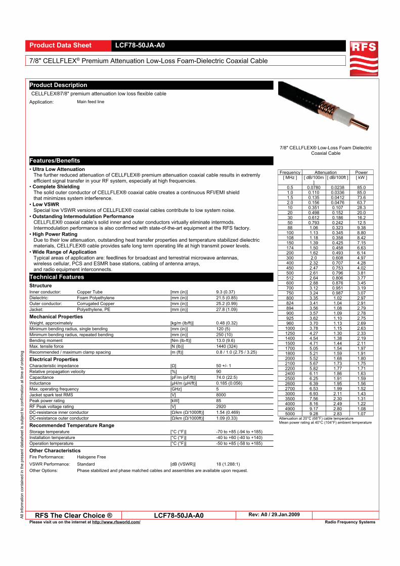
SINGLE-LEVEL PARTS LIST Change no. Effective from: 9.01.0275919516-80 Printout: 9.01.12 Page: 1cablingKommission: Alt.: Var.:0 0================================================================================Pos. Tp K Component Description Quantity QU D--------------------------------------------------------------------------------0010 NP 914573 Cellflex-cable LCF78-50JA 28,000 M
0020 NP 0921965 cable connector 7/8" EIA for LCF 78 8,000 ST
0030 NP 169134 protective cap EIA 7/8" 8,000 ST
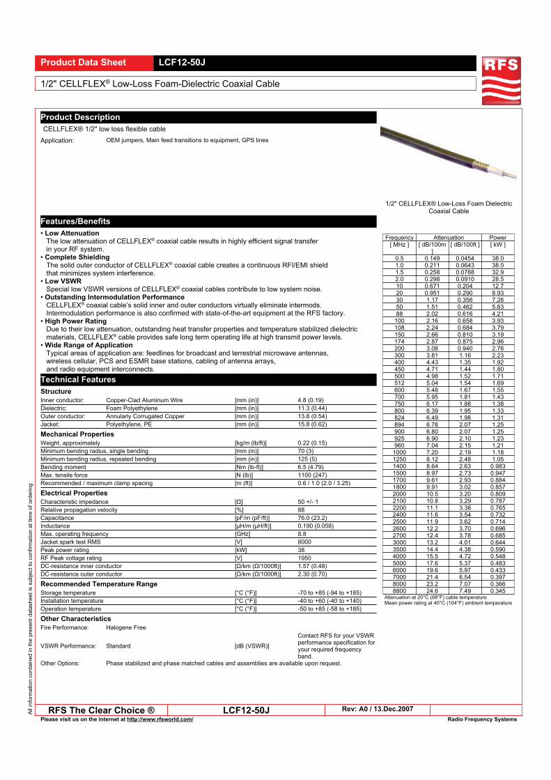
0040 NP 914590 cellflex-cable LCF12-50J 30,000 M
0050 NP 0921470 connector 7-16 for 1/2" Cellflex 32,000 ST
0060 NP 018110 protective cap 7/16-STI 32,000 ST
* * * The End * * *
Blatt/Sheet: Name/Sign:BCA/St
Typ Nr./Type No.:759 19516
UHF Antenna TNU CH30Montevideo
Uruguay/KMB
Tag/Date:25.02.2012
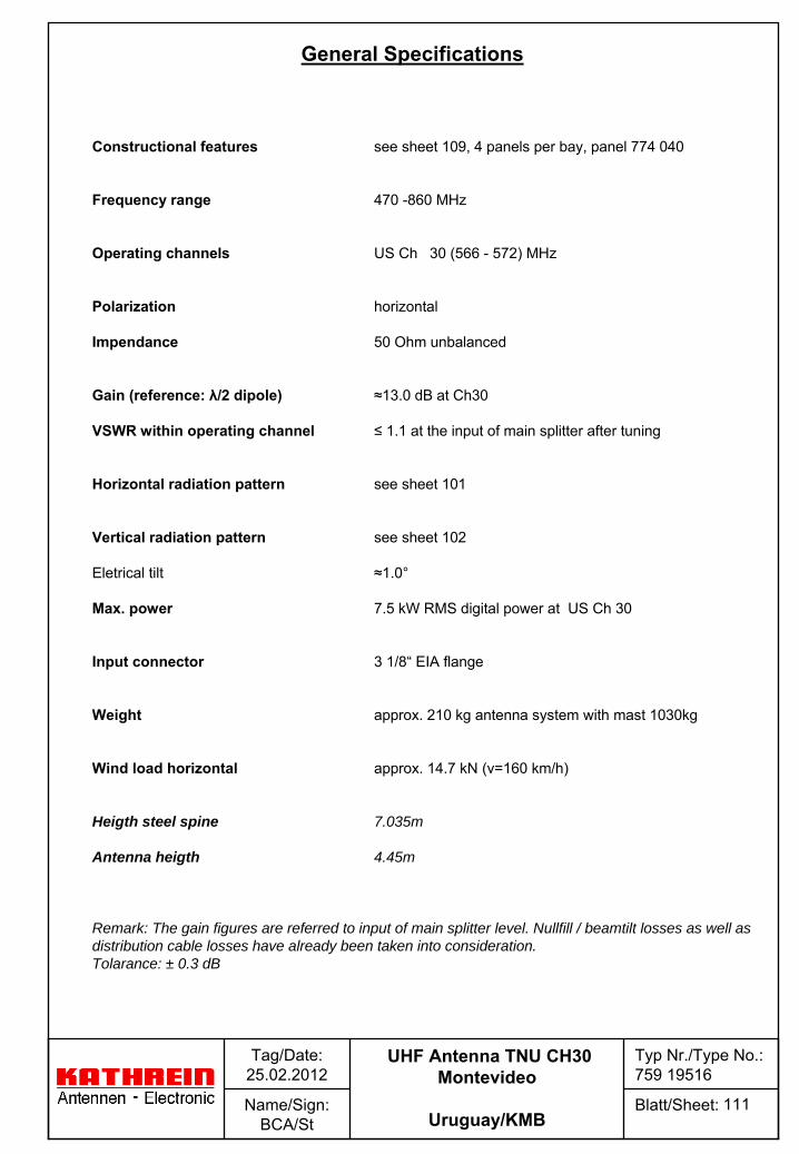
Constructional
features
see
sheet
109, 4 panels
per bay, panel
774 040
Frequency
range
470 -860 MHz
Operating
channels
US Ch
30 (566 -
572) MHz
Polarization
horizontal
Impendance
50 Ohm unbalanced
Gain
(reference: λ/2 dipole)
≈13.0 dB at Ch30
VSWR within
operating
channel
≤
1.1 at the
input
of main
splitter
after
tuning
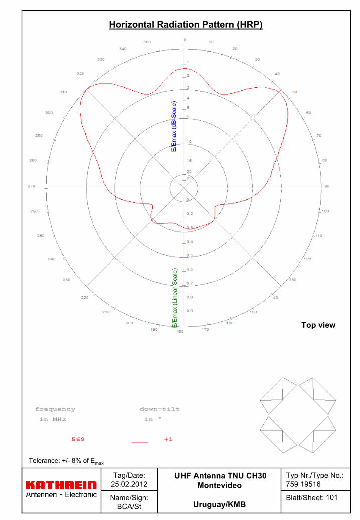
Horizontal radiation
pattern
see
sheet
101
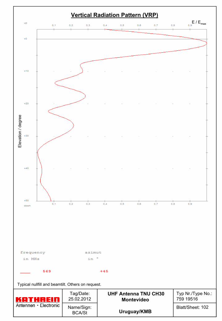
Vertical
radiation
pattern
see
sheet
102
Eletrical
tilt
≈1.0°
Max. power
7.5 kW RMS digital power at US Ch
30
Input connector
3 1/8“
EIA flange
Weight
approx. 210 kg antenna
system
with
mast
1030kg
Wind load
horizontal
approx. 14.7 kN (v=160 km/h)
Heigth steel spine 7.035m
Antenna heigth 4.45m
Remark: The gain figures are referred to input of main splitter level. Nullfill / beamtilt losses as well as distribution cable losses have already been taken into consideration. Tolarance: ± 0.3 dB
111
General Specifications
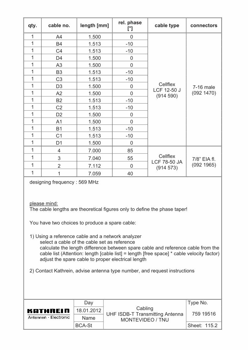
qty. cable no. length [mm] rel. phase [°] cable type connectors
1 A4 1.500 0 1 B4 1.513 -10 1 C4 1.513 -10 1 D4 1.500 0 1 A3 1.500 0 1 B3 1.513 -10 1 C3 1.513 -10 1 D3 1.500 0 1 A2 1.500 0 1 B2 1.513 -10 1 C2 1.513 -10 1 D2 1.500 0 1 A1 1.500 0 1 B1 1.513 -10 1 C1 1.513 -10 1 D1 1.500 0
Cellflex LCF 12-50 J
(914 590)
7-16 male (092 1470)
1 4 7.000 85 1 3 7.040 55 1 2 7.112 0 1 1 7.059 40
Cellflex LCF 78-50 JA
(914 573)
7/8” EIA fl. (092 1965)
designing frequency : 569 MHz
please mind:The cable lengths are theoretical figures only to define the phase taper!
You have two choices to produce a spare cable:
1) Using a reference cable and a network analyzer select a cable of the cable set as reference calculate the length difference between spare cable and reference cable from the cable list (Attention: length [cable list] = length [free space] * cable velocity factor) adjust the spare cable to proper electrical length
2) Contact Kathrein, advise antenna type number, and request instructions
Day Type No. 18.01.2012
Name759 19516
BCA-St
CablingUHF ISDB-T Transmitting Antenna
MONTEVIDEO / TNU Sheet: 115.2
Blatt/Sheet: Name/Sign:BCA/St
Typ Nr./Type No.:759 19516
UHF Antenna TNU CH30Montevideo
Uruguay/KMB
Tag/Date:25.02.2012
E/E
max
(dB
-Sca
le)
E/E
max
(Lin
ear
Sca
le)
Tolerance: +/-
8% of Emax
101
Horizontal Radiation
Pattern (HRP)
Top view
Blatt/Sheet: Name/Sign:BCA/St
Typ Nr./Type No.:759 19516
UHF Antenna TNU CH30Montevideo
Uruguay/KMB
Tag/Date:25.02.2012
E / EmaxE
leva
tion
/ deg
ree
102
Typical
nullfill
and beamtilt. Others
on request.
Vertical
Radiation
Pattern (VRP)
936.
1643
/c
S
ubje
ct t
o al
tera
tion.
Page 2 of 2 774 038, ...
KATHREIN-Werke KG . Anton-Kathrein-Straße 1 – 3 . P.O. Box 10 04 44 . 83004 Rosenheim . Germany . Phone +49 8031 184-0 . Fax +49 8031 184-495
Internet: http://www.kathrein.de
Type No. white 774 040 774 046 774 038Order No. orange 774 041 774 047 774 039
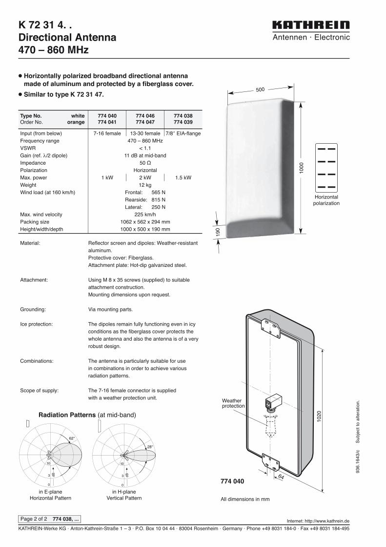
● Horizontally polarized broadband directional antennamade of aluminum and protected by a fiberglass cover.
● Similar to type K 72 31 47.
1020
64
Weatherprotection
3 dB
10
0
62°
3 dB
10
0
28°
in E-planeHorizontal Pattern
in H-planeVertical Pattern
K 72 31 4. .Directional Antenna470 – 860 MHz
Material: Reflector screen and dipoles: Weather-resistantaluminum.Protective cover: Fiberglass.Attachment plate: Hot-dip galvanized steel.
Attachment: Using M 8 x 35 screws (supplied) to suitableattachment construction.Mounting dimensions upon request.
Grounding: Via mounting parts.
Ice protection: The dipoles remain fully functioning even in icyconditions as the fiberglass cover protects thewhole antenna and also the antenna is of a veryrobust design.
Combinations: The antenna is particularly suitable for use in combinations in order to achieve variousradiation patterns.
Scope of supply: The 7-16 female connector is supplied with a weather protection unit.
Input (from below) 7-16 female 13-30 female 7/8� EIA-flangeFrequency range 470 – 860 MHzVSWR < 1.1Gain (ref. �/2 dipole) 11 dB at mid-bandImpedance 50 �Polarization HorizontalMax. power 1 kW 2 kW 1.5 kWWeight 12 kgWind load (at 160 km/h) Frontal: 565 N
Rearside: 815 NLateral: 250 N
Max. wind velocity 225 km/hPacking size 1062 x 562 x 294 mmHeight/width/depth 1000 x 500 x 190 mm
Radiation Patterns (at mid-band)
All dimensions in mm
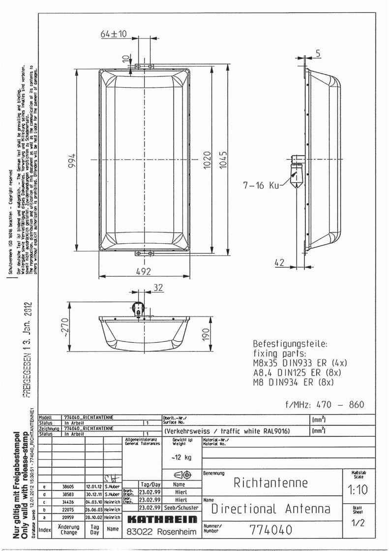
774 040
1000
190
500
Horizontalpolarization
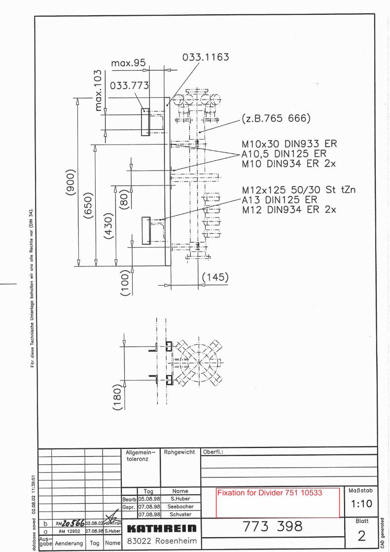
Fixation for Divider 751 10533
166 ||
SPINNER || BROADCAST
Data subject to change without notice – Edition D
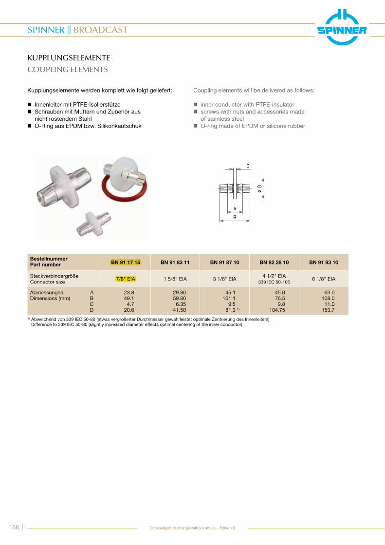
KUPPLUNGSELEMENTE
COUPLING ELEMENTS
Kupplungselemente werden komplett wie folgt geliefert:
� Innenleiter mit PTFE-Isolierstütze � Schrauben mit Muttern und Zubehör aus nicht rostendem Stahl
� O-Ring aus EPDM bzw. Silikonkautschuk
Coupling elements will be delivered as follows:
� inner conductor with PTFE-insulator � screws with nuts and accessories made of stainless steel
� O-ring made of EPDM or silicone rubber
Bestellnummer
Part number BN 91 17 15 BN 91 83 11 BN 91 87 10 BN 82 28 10 BN 91 93 10
Steckverbindergröße Connector size 7/8" EIA 1 5/8" EIA 3 1/8" EIA 4 1/2" EIA
339 IEC 50-1056 1/8" EIA
Abmessungen A Dimensions (mm) B C D
23.8 49.1 4.7 20.6
29.80 59.80 6.35 41.50
45.1 101.1 9.5 81.3 1)
45.0 76.5 9.8 104.75
63.0 108.0 11.0 153.7
1) Abweichend von 339 IEC 50-80 (etwas vergrößerter Durchmesser gewährleistet optimale Zentrierung des Innenleiters) Difference to 339 IEC 50-80 (slightly increased diameter effects optimal centering of the inner conductor)
7/8" EIA
BN 91 17 15
|| 165
SPINNER || BROADCAST
Data subject to change without notice – Edition D
Verb
ind
ung
ssys
tem
e &
Mes
szub
ehö
r
Co
nnec
ting
Sys
tem
s &
Mo
nito
ring
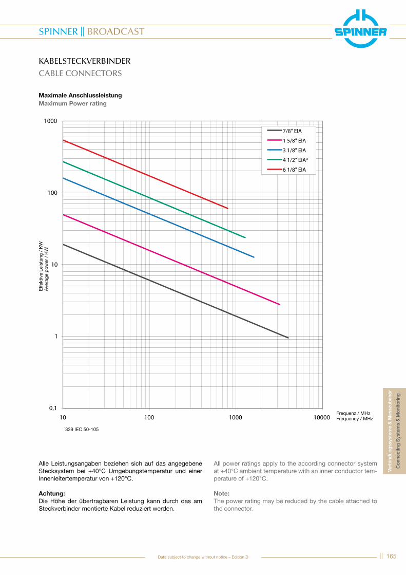
KABELSTECKVERBINDER
CABLE CONNECTORS
Maximale Anschlussleistung
Maximum Power rating
Alle Leistungsangaben beziehen sich auf das angegebene Stecksystem bei +40°C Umgebungstemperatur und einer Innenleitertemperatur von +120°C.
Achtung:
Die Höhe der übertragbaren Leistung kann durch das am Steckverbinder montierte Kabel reduziert werden.
All power ratings apply to the according connector system at +40°C ambient temperature with an inner conductor tem-perature of +120°C.
Note:
The power rating may be reduced by the cable attached to the connector.
Frequenz / MHzFrequency / MHz
Effe
ktiv
e Le
istu
ng /
KW
Ave
rage
pow
er /
KW
*339 IEC 50-105
164 ||
SPINNER || BROADCAST
Data subject to change without notice – Edition D
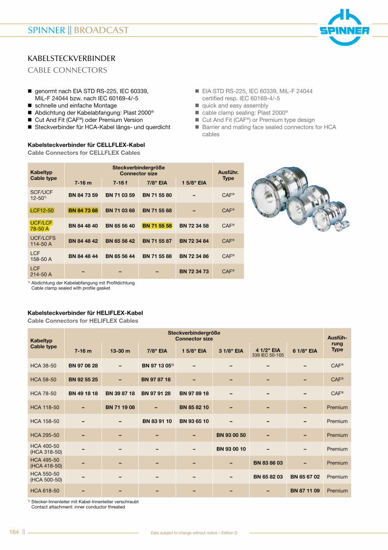
KABELSTECKVERBINDER
CABLE CONNECTORS
� genormt nach EIA STD RS-225, IEC 60339, MiL-F 24044 bzw. nach IEC 60169-4/-5
� schnelle und einfache Montage � Abdichtung der Kabelabfangung: Plast 2000®
� Cut And Fit (CAF®) oder Premium Version � Steckverbinder für HCA-Kabel längs- und querdicht
� EIA STD RS-225, IEC 60339, MiL-F 24044 certified resp. IEC 60169-4/-5
� quick and easy assembly � cable clamp sealing: Plast 2000®
� Cut And Fit (CAF®) or Premium type design � Barrier and mating face sealed connectors for HCA cables
Kabeltyp
Cable type
Steckverbindergröße
Connector size Ausfüh-
rung
Type7-16 m 13-30 m 7/8" EIA 1 5/8" EIA 3 1/8" EIA 4 1/2" EIA339 IEC 50-105
6 1/8" EIA
HCA 38-50 BN 97 06 28 – BN 97 13 051) – – – – CAF®
HCA 58-50 BN 92 55 25 – BN 97 87 18 – – – – CAF®
HCA 78-50 BN 49 18 18 BN 39 87 18 BN 97 91 28 BN 97 89 18 – – – CAF®
HCA 118-50 – BN 71 19 08 – BN 85 82 10 – – – Premium
HCA 158-50 – – BN 83 91 10 BN 93 65 10 – – – Premium
HCA 295-50 – – – – BN 93 00 50 – – Premium
HCA 400-50(HCA 318-50) – – – – BN 93 00 10 – – Premium
HCA 495-50(HCA 418-50) – – – – – BN 83 86 03 – Premium
HCA 550-50(HCA 500-50) – – – – – BN 65 82 03 BN 65 67 02 Premium
HCA 618-50 – – – – – – BN 87 11 09 Premium
1) Stecker-Innenleiter mit Kabel-Innenleiter verschraubt Contact attachment: inner conductor threated
Kabelsteckverbinder für CELLFLEX-Kabel
Cable Connectors for CELLFLEX Cables
Kabelsteckverbinder für HELIFLEX-Kabel
Cable Connectors for HELIFLEX Cables
Kabeltyp
Cable type
Steckverbindergröße
Connector size Ausführ.
Type7-16 m 7-16 f 7/8" EIA 1 5/8" EIA
SCF/UCF12-501) BN 84 73 59 BN 71 03 59 BN 71 55 80 – CAF®
LCF12-50 BN 84 73 68 BN 71 03 68 BN 71 55 68 – CAF®
UCF/LCF 78-50 A BN 84 48 40 BN 65 56 40 BN 71 55 58 BN 72 34 58 CAF®
UCF/LCFS 114-50 A BN 84 48 42 BN 65 56 42 BN 71 55 87 BN 72 34 84 CAF®
LCF 158-50 A BN 84 48 44 BN 65 56 44 BN 71 55 88 BN 72 34 86 CAF®
LCF 214-50 A – – – BN 72 34 73 CAF®
1) Abdichtung der Kabelabfangung mit Profildichtung Cable clamp sealed with profile gasket
LCF12-50 BN 84 73 68
UCF/LCF78-50 A BN 71 55 58
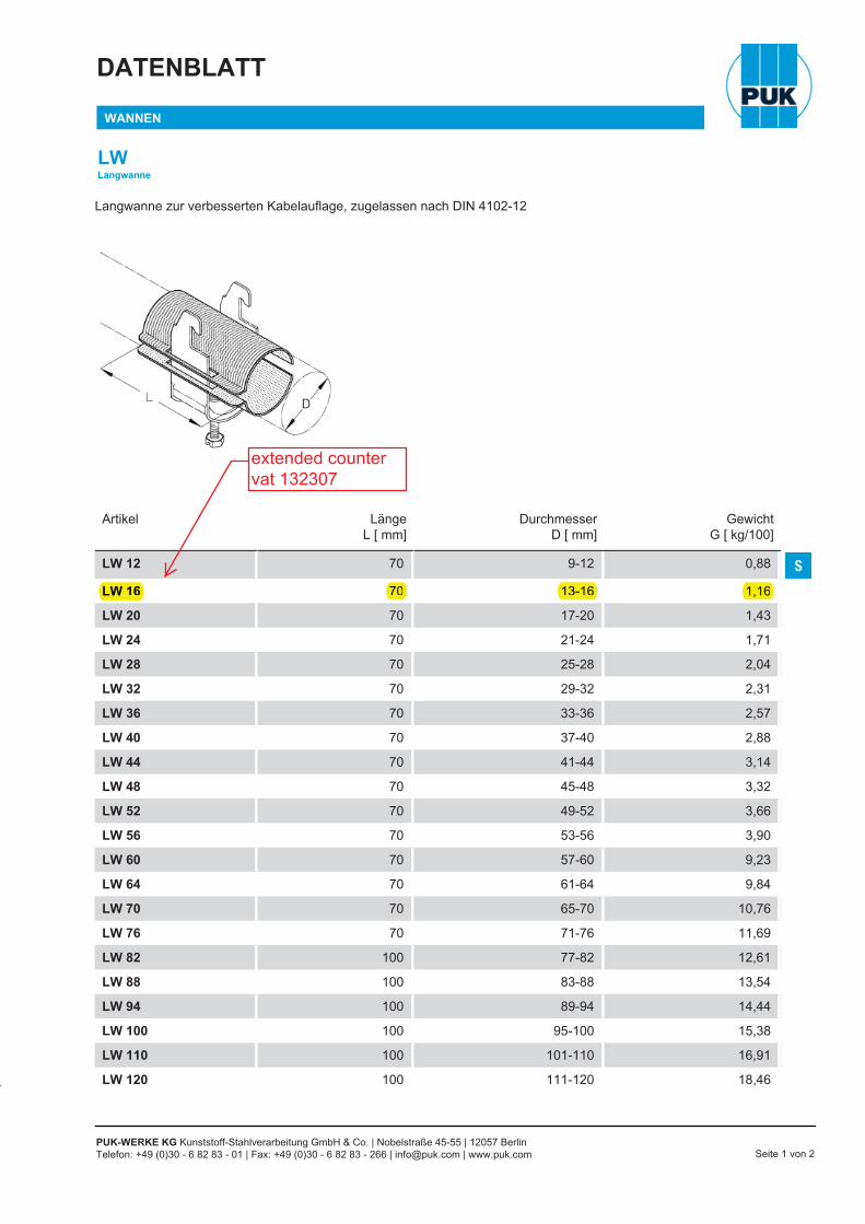
DATENBLATT
WANNEN
LWLangwanne
PUK-WERKE KG Kunststoff-Stahlverarbeitung GmbH & Co. | Nobelstraße 45-55 | 12057 BerlinTelefon: +49 (0)30 - 6 82 83 - 01 | Fax: +49 (0)30 - 6 82 83 - 266 | [email protected] | www.puk.com Seite 1 von 2
Langwanne zur verbesserten Kabelauflage, zugelassen nach DIN 4102-12
Artikel LängeL [ mm]
DurchmesserD [ mm]
GewichtG [ kg/100]
LW 12 70 9-12 0,88
LW 16 70 13-16 1,16
LW 20 70 17-20 1,43
LW 24 70 21-24 1,71
LW 28 70 25-28 2,04
LW 32 70 29-32 2,31
LW 36 70 33-36 2,57
LW 40 70 37-40 2,88
LW 44 70 41-44 3,14
LW 48 70 45-48 3,32
LW 52 70 49-52 3,66
LW 56 70 53-56 3,90
LW 60 70 57-60 9,23
LW 64 70 61-64 9,84
LW 70 70 65-70 10,76
LW 76 70 71-76 11,69
LW 82 100 77-82 12,61
LW 88 100 83-88 13,54
LW 94 100 89-94 14,44
LW 100 100 95-100 15,38
LW 110 100 101-110 16,91
LW 120 100 111-120 18,46
LW 16 70 13-16 1,16
extended countervat 132307
������� � �� � �������������
���� ������� � ����� ����������� �������� ����������� �� ������� �����
���
����
���
���
����
����
!��
�"�
# ��
���!
����
"���
����
�$��
���
����
� ���
���
�����
���
� !�
��%
��� �� �� � ����� � ������������� � �� �� � !"�#" ��!�� $ ��$�� �$ �# �� �#� �# � � ���%���&&&"�'$&����"��(� ���� �� )� #�* �*$� ($
������� $���%���#
���� ������� �������� ��� ������� ��������� �����
����������� # ����� ����������� ��� ���� �������� ������##��������' *��� ���! ����
� ��� $�+ # '��$; ,��� ��& ��� #����#<<<="� �� �"� �!���! ����������� �� ������� # ����� ����������� ������� ����� ������ �� ��� ���><<<��������� ��%��� � ����� �� >�� ? �>����E ��#������> �� "�%" � �J�������M; ��(%� � ��� ���#-<<<="� ����! ���� ���!���� �� ������� ������� ����� � ����� � ���������� ?O��*O �"���!<<<�"�� ������P�� �>���� ���� �� ����M; ��& .�/�<<<Q#����� ��� RQU? V� ����� �� ������� ������� ������ ���� ����� �� ��� �>���� �����M; 0��$�#��#- 1#� �(�������# � �'��(#� <<<������� ������� �����W� ����! ���� ��! ���� ���!���� � V� �����> ��������� ���� ��!�M<<<O��� ��!������� #� �� ����� �� ���� ����� ��! ���" ����������"��� � �J��#���� �� �"� ?Q ����� >M; 2�-� ��& � ���#-<<<��� �� �"�� ��� �����������E �������!��% "��� � ����� # �#� ���� ��! ���#� ��� � �������P�! !������ ��<<<���� ����E ������� ����� # �V�!�� ���� ���% �� � �#� ����% ���� �� "�%" � ������ #��� ��V���M; /�� �#- �' �%%������#<<<=>#���� � ��� �� �##�������� � �' ���!����� �� � ��!���� ��! �� ��� ��� ��� ���V� ��������E<<<�� ����� ������� E ��Q ��! �Q*? ���� ��������E ������% �� ������� � �>�E<<<��! �!�� �J��#���� ���� ��������M
�J����> ����������� ���� X *YP Z X !\�^__�
ZX !\�^__�� Z X `U Z
_Md _M_��_ _M_jq� �dM_^M_ _M^^_ _M_qqy �dM_^Md _M^qd _M_{^j �qMyjM_ _M^dy _M_{�y yqM�^_ _Mqd^ _M^_� j�Mqj_ _M{}� _M^dj j_M_q_ _My^j _M^�y ^yMjd_ _M�}q _Mj{j ^jMd�� ^M_y _Mqjq }Mq�
^__ ^M^q _Mq{d �M�_^_� ^M^� _Mqd� �M{j^d_ ^Mq} _M{jd �M^d^�{ ^Md_ _M{d� yMyqj__ ^Myj _M{}q yM^{q__ jM_ _My_� {M}�{__ jMqj _M�_� {Mj�{d_ jM{� _M�dq {M_jd__ jMy^ _M�}y qM�^d^j jMy{ _M�_y qM��y__ jM�� _M��y qM{d�__ qM^j _M}d^ qM^}�d_ qMj{ _M}�� qM_��__ qMqd ^M_j jM}��j{ qM{^ ^M_{ jM}^�}{ qMdy ^M_� jM�}}__ qMd� ^M_} jM��}jd qMyj ^M^_ jM�d}y_ qM�_ ^M^q jMy}
^___ qM�� ^M^d jMyq^jd_ {Mj� ^Mq_ jMqq^{__ {Md{ ^Mq� jM^}^d__ {M�^ ^M{{ jM^^^�__ dM_d ^Md{ ^M}�^�__ dMj^ ^Md} ^M}^j___ dMdj ^My� ^M�_j^__ dMy� ^M�q ^M�djj__ dM�j ^M�� ^M�^j{__ yM^^ ^M�y ^Myqjd__ yMjd ^M}^ ^Md}jy__ yMq} ^M}d ^Mdyj�__ yMdq ^M}} ^Mdjq___ yM}q jM^^ ^M{qqd__ �Mdy jMq_ ^Mq^{___ �M^y jM{} ^Mjj{}__ }M^� jM�_ ^M_�d___ }Mj� jM�q ^M_�
����������� �� j_~� �y�~� ����� ���#� ��� �*��� #��� ����% �� {_~� �^_{~� ������� ���#� ��� �
� ��#��� � ��� $�������� O��� ���!���� ' ��##� =��� X�� ����Z }Mq �_Mq��������� ��' ��� ���>��">���� X�� ����Z j^Md �_M�d����� ���!���� ' �� �%���! ��##� X�� ����Z jdMj �_M}}����`��' ���>��">����E �� X�� ����Z j�M� �^M_}�
3 ��#��� ���% ��� $U��%"�E �## ��������> X`%�� �������Z _M{� �_Mqj�*������ ���!��% �!���E ���%�� ���!��% X�� ����Z ^j_ �d�*������ ���!��% �!���E �#����! ���!��% X�� ����Z jd_ �^_�\��!��% ������ X�� �������Z ^qM_ �}My�*��M ������� �� �� X� ����Z ^{{_ �qj{�?�������!�! � ������� ����# �#����% X� ����Z _M� � ^M_ �jM�d � qMjd�
4� ������ ���% ��� $�"� ���� ����� ��#�!���� X�Z d_ ��� ^?�����V� # �#�%����� V������> X�Z }_��#�������� X#�� �#����Z �{M_ �jjMd�O�!������� X�Y�� ��Y����Z _M^�d �_M_dy�*��M �#� ����% � �J����> X�YPZ d���`�� �#� ` ���� ?*Q XRZ �___���` #��� ����% X`UZ �d? ���` V����%� ����% XRZ j}j_��� ��������� ���� ���!���� X��`� ���^___���Z ^Md{ �_M{y}���� ��������� ���� ���!���� X��`� ���^___���Z ^M_} �_Mqq�
� ��(( #� � � (% ���� �#- Q�� �%� ���#� ��� � X~� �~�Z ��_ �� ��d ��}{ �� �^�d�O����������� ���#� ��� � X~� �~�Z �{_ �� �y_ ��{_ �� �^{_��#� ����� ���#� ��� � X~� �~�Z �d_ �� ��d ��d� �� �^�d�
0�� � ����� ��$���$� � �� �� �����' Y���%��� ��RQU? �� �� �����' Q���!� ! X!\ �RQU?�Z ^� �^Mj��'^���"� �#�����' �"��� �������P�! ��! #"��� ����"�! ������ ��! ���������� � � �V������� �#�� �J����M
������� � �� � ���5 ����
^�j� ������� �������� ����������� �� ������� �����
���
����
���
���
����
����
!��
�"�
# ��
���!
����
"���
����
�$��
���
����
� ���
���
�����
���
� !�
��%
��� �� �� � ����� � ���5 ���� � �� �� � 56" �" ����� $ ��$�� �$ �# �� �#� �# � � ���%���&&&"�'$&����"��(� ���� �� )� #�* �*$� ($
������� $���%���#
^�j� ������� �������� ��� ������� ��������� �����
������� ^�j� ��� ���� �������� ������##��������' ��* $��#� �E *��� ���! � ��������� �� �J��#����E ��Q �����
� ��� $�+ # '��$; ��& ��� #����#<<<="� ��� ����������� �� ������� ������� ����� ������ �� "�%"�> ��������� ��%��� � ����� <<<�� >�� ? �>����M; ��(%� � ��� ���#-<<<="� ����! ���� ���!���� �� ������� ������� ����� � ����� � ���������� ?O��*O �"���!<<<�"�� ������P�� �>���� ���� �� ����M; ��& .�/�<<<Q#����� ��� RQU? V� ����� �� ������� ������� ������ ���� ����� �� ��� �>���� �����M; 0��$�#��#- 1#� �(�������# � �'��(#� <<<������� ������� �����W� ����! ���� ��! ���� ���!���� � V� �����> ��������� ���� ��!�M<<<O��� ��!������� #� �� ����� �� ���� ����� ��! ���" ����������"��� � �J��#���� �� �"� ?Q ����� >M; 2�-� ��& � ���#-<<<��� �� �"�� ��� �����������E �������!��% "��� � ����� # �#� ���� ��! ���#� ��� � �������P�! !������ ��<<<���� ����E ������� ����� # �V�!�� ���� ���% �� � �#� ����% ���� �� "�%" � ������ #��� ��V���M; /�� �#- �' �%%������#<<<=>#���� � ��� �� �##�������� � �' ���!����� �� � ��!���� ��! �� ��� ��� ��� ���V� ��������E<<<�� ����� ������� E ��Q ��! �Q*? ���� ��������E ������% �� ������� � �>�E<<<��! �!�� �J��#���� ���� ��������M
�J����> ����������� ���� X *YP Z X !\�^__�
ZX !\�^__�� Z X `U Z
_Md _M^{} _M_{d{ q�M_^M_ _Mj^^ _M_y{q q�M_^Md _Mjd� _M_��� qjM}jM_ _Mj}� _M_}^_ j�Md^_ _My�^ _Mj_{ ^jM�j_ _M}d^ _Mj}_ �M}qq_ ^M^� _Mqdy �Mjyd_ ^Md^ _M{yj dMyq�� jM_j _My^y {Mj^
^__ jM^y _Myd� qM}q^_� jMj{ _My�{ qM�}^d_ jMyy _M�^_ qM^}^�{ jM�� _M��d jM}yj__ qM_� _M}{_ jM�yq__ qM�^ ^M^y jMjq{__ {M{q ^Mqd ^M}j{d_ {M�^ ^M{{ ^M�_d__ {M}� ^Mdj ^M�^d^j dM_{ ^Md{ ^My}y__ dM{� ^My� ^Mdd�__ dM}d ^M�^ ^M{q�d_ yM^� ^M�� ^Mq��__ yMq} ^M}d ^Mqq�j{ yM{} ^M}� ^Mq^�}{ yM�� jM_� ^Mjd}__ yM�_ jM_� ^Mjd}jd yM}_ jM^_ ^Mjq}y_ �M_{ jM^d ^Mj^
^___ �Mj_ jM^} ^M^�^jd_ �M^j jM{� ^M_d^{__ �My{ jMyq _M}�q^d__ �M}� jM�q _M}{�^�__ }My^ jM}q _M��{^�__ }M}^ qM_j _M�d�j___ ^_Md qMj_ _M�_}j^__ ^_M� qMj} _M���jj__ ^^M^ qMq� _M�ydj{__ ^^My qMd{ _M�qjjd__ ^^M} qMyj _M�^{jy__ ^jMj qM�_ _My}yj�__ ^jM{ qM�� _My�dq___ ^qMj {M_^ _My{{qd__ ^{M{ {Mq� _Md}_{___ ^dMd {M�j _Md{�d___ ^�My dMq� _M{�qy___ ^}My dM}� _M{qq�___ j^M{ yMd{ _Mq}��___ jqMj �M_� _Mqyy��__ j{My �M{} _Mq{d
����������� �� j_~� �y�~� ����� ���#� ��� �*��� #��� ����% �� {_~� �^_{~� ������� ���#� ��� �
� ��#��� � ��� $�������� O��� ���!���� ' ��##� ����! �������� U� � X�� ����Z {M� �_M^}�������� ��' ��� ���>��">���� X�� ����Z ^^Mq �_M{{����� ���!���� ' ������ �> �� �%���! ��##� X�� ����Z ^qM� �_Md{����`��' ���>��">����E �� X�� ����Z ^dM� �_Myj�
3 ��#��� ���% ��� $U��%"�E �## ��������> X`%�� �������Z _Mjj �_M^d�*������ ���!��% �!���E ���%�� ���!��% X�� ����Z �_ �q�*������ ���!��% �!���E �#����! ���!��% X�� ����Z ^jd �d�\��!��% ������ X�� �������Z yMd �{M�}�*��M ������� �� �� X� ����Z ^^__ �j{��?�������!�! � ������� ����# �#����% X� ����Z _My � ^M_ �jM_ � qMjd�
4� ������ ���% ��� $�"� ���� ����� ��#�!���� X�Z d_ ��� ^?�����V� # �#�%����� V������> X�Z ����#�������� X#�� �#����Z �yM_ �jqMj�O�!������� X�Y�� ��Y����Z _M^}_ �_M_d��*��M �#� ����% � �J����> X�YPZ �M����`�� �#� ` ���� ?*Q XRZ �___���` #��� ����% X`UZ q�? ���` V����%� ����% XRZ ^}d_��� ��������� ���� ���!���� X��`� ���^___���Z ^Md� �_M{����� ��������� ���� ���!���� X��`� ���^___���Z jMq_ �_M�_�
� ��(( #� � � (% ���� �#- Q�� �%� ���#� ��� � X~� �~�Z ��_ �� ��d ��}{ �� �^�d�O����������� ���#� ��� � X~� �~�Z �{_ �� �y_ ��{_ �� �^{_��#� ����� ���#� ��� � X~� �~�Z �d_ �� ��d ��d� �� �^�d�
0�� � ����� ��$���$� � �� �� �����' Y���%��� ��
RQU? �� �� �����' Q���!� ! X!\ �RQU?�Z
������� ?Q �� >�� RQU?#� �� ����� �#����������� �� >�� �J�� �! � �J����>���!M
��"� �#�����' �"��� �������P�! ��! #"��� ����"�! ������ ��! ���������� � � �V������� �#�� �J����M


![[Laptrinh.vn]-Ly Thuyet Anten](https://img.pdfslide.net/doc/110x75/5571fc884979599169976fa2/laptrinhvn-ly-thuyet-anten.jpg)