Embed Size (px)
Citation preview
Syllabus for the Trade
of
TECHNICIAN POWER ELECTRONICS SYSTEMS
(SEMESTER PATTERN)
UNDER
CRAFTSMAN TRAINING SCHEME
Re-designed in
2014
By
Government of India
Directorate General of Employment & Training
Ministry of Labour & Employment (DGET)
2
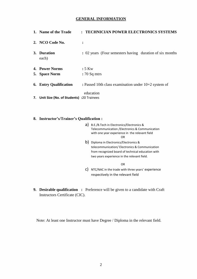
GENERAL INFORMATION
1. Name of the Trade : TECHNICIAN POWER ELECTRONICS SYSTEMS
2. NCO Code No. :
3. Duration : 02 years (Four semesters having duration of six months
each)
4. Power Norms : 5 Kw
5. Space Norm : 70 Sq mtrs
6. Entry Qualification : Passed 10th class examination under 10+2 system of
education 7. Unit Size (No. of Students) :20 Trainees
8. Instructor’s/Trainer’s Qualification :
9. Desirable qualification : Preference will be given to a candidate with Craft
Instructors Certificate (CIC).
Note: At least one Instructor must have Degree / Diploma in the relevant field.
a) B.E./B.Tech in Electronics/Electronics & Telecommunication /Electronics & Communication with one year experience in the relevant field
OR
b) Diploma in Electronics/Electronics &
telecommunication/ Electronics & Communication
from recognized board of technical education with
two years experience in the relevant field.
OR
c) NTC/NAC in the trade with three years’ experience
respectively in the relevant field
3
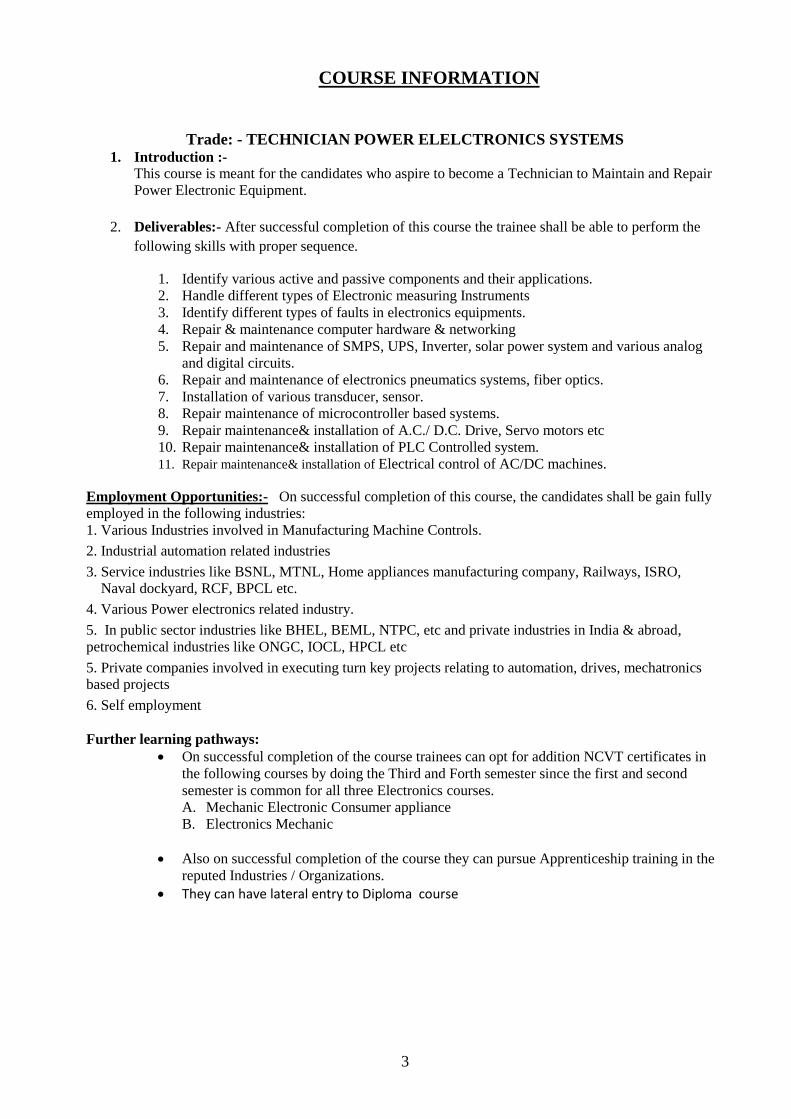
COURSE INFORMATION
Trade: - TECHNICIAN POWER ELELCTRONICS SYSTEMS 1. Introduction :-
This course is meant for the candidates who aspire to become a Technician to Maintain and Repair
Power Electronic Equipment.
2. Deliverables:- After successful completion of this course the trainee shall be able to perform the
following skills with proper sequence.
1. Identify various active and passive components and their applications.
2. Handle different types of Electronic measuring Instruments
3. Identify different types of faults in electronics equipments.
4. Repair & maintenance computer hardware & networking
5. Repair and maintenance of SMPS, UPS, Inverter, solar power system and various analog
and digital circuits.
6. Repair and maintenance of electronics pneumatics systems, fiber optics.
7. Installation of various transducer, sensor.
8. Repair maintenance of microcontroller based systems.
9. Repair maintenance& installation of A.C./ D.C. Drive, Servo motors etc
10. Repair maintenance& installation of PLC Controlled system.
11. Repair maintenance& installation of Electrical control of AC/DC machines.
Employment Opportunities:- On successful completion of this course, the candidates shall be gain fully
employed in the following industries:
1. Various Industries involved in Manufacturing Machine Controls.
2. Industrial automation related industries
3. Service industries like BSNL, MTNL, Home appliances manufacturing company, Railways, ISRO, Naval dockyard, RCF, BPCL etc.
4. Various Power electronics related industry.
5. In public sector industries like BHEL, BEML, NTPC, etc and private industries in India & abroad,
petrochemical industries like ONGC, IOCL, HPCL etc
5. Private companies involved in executing turn key projects relating to automation, drives, mechatronics based projects
6. Self employment
Further learning pathways:
On successful completion of the course trainees can opt for addition NCVT certificates in
the following courses by doing the Third and Forth semester since the first and second
semester is common for all three Electronics courses.
A. Mechanic Electronic Consumer appliance
B. Electronics Mechanic
Also on successful completion of the course they can pursue Apprenticeship training in the
reputed Industries / Organizations.
They can have lateral entry to Diploma course
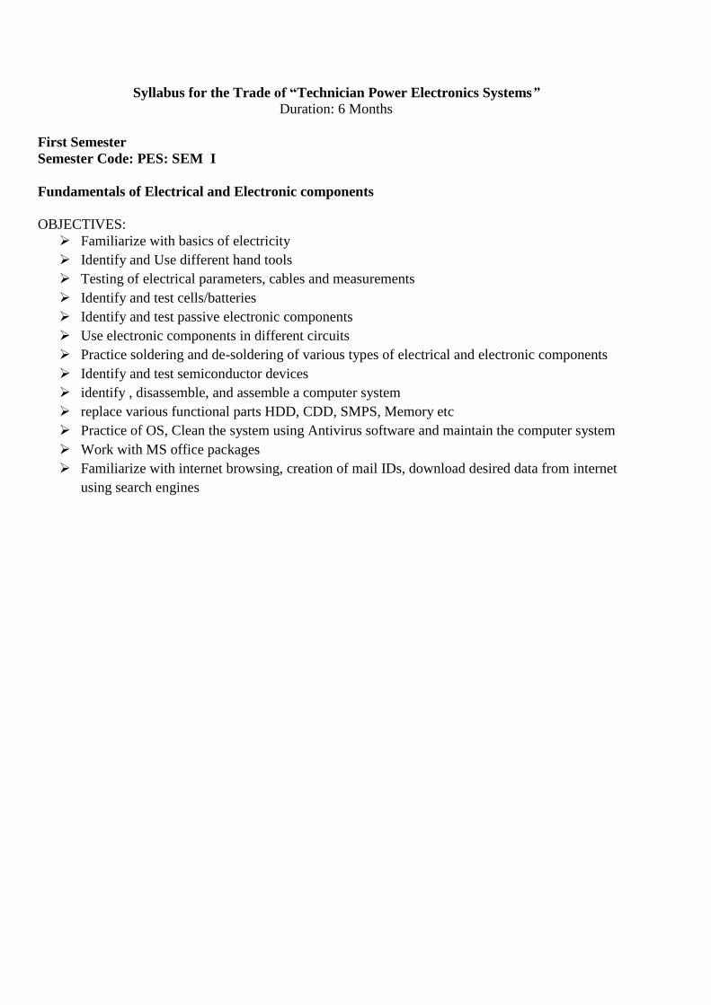
Syllabus for the Trade of “Technician Power Electronics Systems”
Duration: 6 Months
First Semester
Semester Code: PES: SEM I
Fundamentals of Electrical and Electronic components
OBJECTIVES:
Familiarize with basics of electricity
Identify and Use different hand tools
Testing of electrical parameters, cables and measurements
Identify and test cells/batteries
Identify and test passive electronic components
Use electronic components in different circuits
Practice soldering and de-soldering of various types of electrical and electronic components
Identify and test semiconductor devices
identify , disassemble, and assemble a computer system
replace various functional parts HDD, CDD, SMPS, Memory etc
Practice of OS, Clean the system using Antivirus software and maintain the computer system
Work with MS office packages
Familiarize with internet browsing, creation of mail IDs, download desired data from internet
using search engines
5
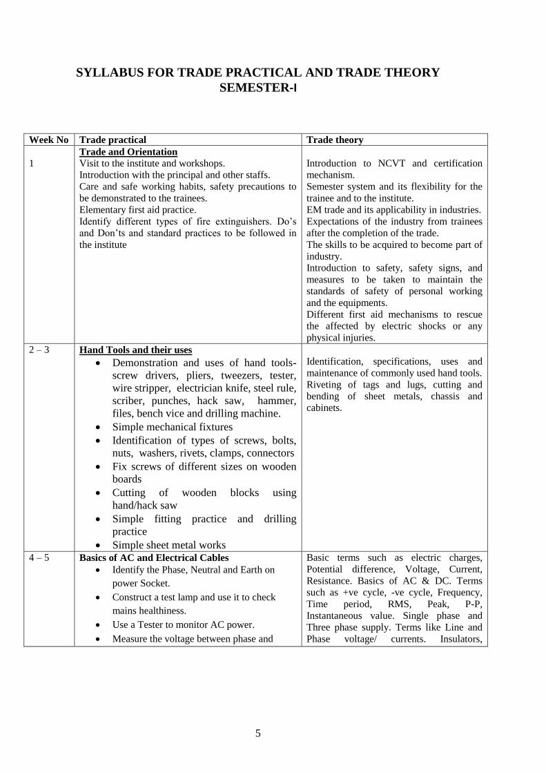
SYLLABUS FOR TRADE PRACTICAL AND TRADE THEORY
SEMESTER-I
Week No Trade practical Trade theory
1 Trade and Orientation
Visit to the institute and workshops.
Introduction with the principal and other staffs.
Care and safe working habits, safety precautions to
be demonstrated to the trainees.
Elementary first aid practice.
Identify different types of fire extinguishers. Do’s
and Don’ts and standard practices to be followed in
the institute
Introduction to NCVT and certification
mechanism.
Semester system and its flexibility for the
trainee and to the institute.
EM trade and its applicability in industries.
Expectations of the industry from trainees
after the completion of the trade.
The skills to be acquired to become part of
industry.
Introduction to safety, safety signs, and
measures to be taken to maintain the
standards of safety of personal working
and the equipments.
Different first aid mechanisms to rescue
the affected by electric shocks or any
physical injuries.
2 – 3
Hand Tools and their uses
Demonstration and uses of hand tools-
screw drivers, pliers, tweezers, tester,
wire stripper, electrician knife, steel rule,
scriber, punches, hack saw, hammer,
files, bench vice and drilling machine.
Simple mechanical fixtures
Identification of types of screws, bolts,
nuts, washers, rivets, clamps, connectors
Fix screws of different sizes on wooden
boards
Cutting of wooden blocks using
hand/hack saw
Simple fitting practice and drilling
practice
Simple sheet metal works
Identification, specifications, uses and
maintenance of commonly used hand tools.
Riveting of tags and lugs, cutting and
bending of sheet metals, chassis and
cabinets.
4 – 5 Basics of AC and Electrical Cables
Identify the Phase, Neutral and Earth on
power Socket.
Construct a test lamp and use it to check
mains healthiness.
Use a Tester to monitor AC power.
Measure the voltage between phase and
Basic terms such as electric charges,
Potential difference, Voltage, Current,
Resistance. Basics of AC & DC. Terms
such as +ve cycle, -ve cycle, Frequency,
Time period, RMS, Peak, P-P,
Instantaneous value. Single phase and
Three phase supply. Terms like Line and
Phase voltage/ currents. Insulators,
6
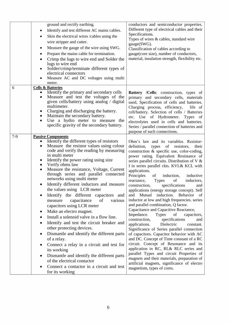
ground and rectify earthing.
Identify and test different AC mains cables.
Skin the electrical wires /cables using the
wire stripper and cutter.
Measure the gauge of the wire using SWG.
Prepare the mains cable for termination.
Crimp the lugs to wire end and Solder the lugs to wire end
Solder/crimp/terminate different types of electrical connectors
Measure AC and DC voltages using multi meter.
conductors and semiconductor properties.
Different type of electrical cables and their
Specifications.
Types of wires & cables, standard wire
gauge(SWG).
Classification of cables according to
gauge(core size), number of conductors,
material, insulation strength, flexibility etc.
6 Cells & Batteries Identify the primary and secondary cells Measure and test the voltages of the
given cells/battery using analog / digital multimeter.
Charging and discharging the battery. Maintain the secondary battery. Use a hydro meter to measure the
specific gravity of the secondary battery.
Battery /Cells: construction, types of
primary and secondary cells, materials
used, Specification of cells and batteries.
Charging process, efficiency, life of
cell/battery. Selection of cells / Batteries
etc. Use of Hydrometer. Types of
electrolytes used in cells and batteries.
Series / parallel connection of batteries and
purpose of such connections.
7-9 Passive Components Identify the different types of resistors Measure the resistor values using colour
code and verify the reading by measuring in multi meter
Identify the power rating using size Verify ohms law Measure the resistance, Voltage, Current
through series and parallel connected networks using multi meter
Identify different inductors and measure
the values using LCR meter
Identify the different capacitors and
measure capacitance of various
capacitors using LCR meter
Make an electro magnet.
Install a solenoid valve in a flow line.
Identify and test the circuit breaker and
other protecting devices.
Dismantle and identify the different parts
of a relay.
Connect a relay in a circuit and test for
its working
Dismantle and identify the different parts
of the electrical contactor
Connect a contactor in a circuit and test
for its working
Ohm’s law and its variables. Resistor-
definition, types of resistors, their
construction & specific use, color-coding,
power rating. Equivalent Resistance of
series parallel circuits. Distribution of V &
I in series parallel ckts. KVL& KCL with
applications.
Principles of induction, inductive
reactance, Types of inductors,
construction, specifications and
applications (energy storage concept). Self
and Mutual induction. Behavior of
inductor at low and high frequencies. series
and parallel combination, Q factor.
Capacitance and Capacitive Reactance,
Impedance. Types of capacitors,
construction, specifications and
applications. Dielectric constant.
Significance of Series parallel connection
of capacitors. Capacitor behavior with AC
and DC. Concept of Time constant of a RC
circuit. Concept of Resonance and its
application in RC, RL& RLC series and
parallel Types and circuit Properties of
magnets and their materials, preparation of
artificial magnets, significance of electro
magnetism, types of cores.
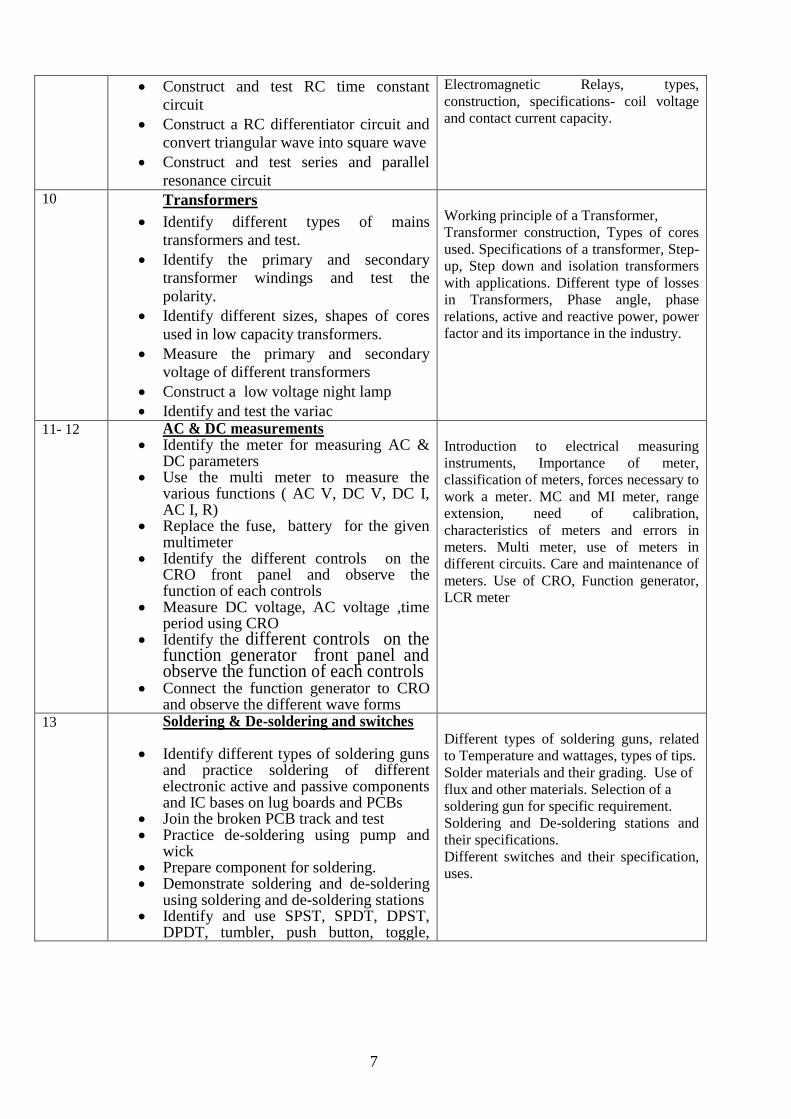
7
Construct and test RC time constant
circuit
Construct a RC differentiator circuit and
convert triangular wave into square wave
Construct and test series and parallel
resonance circuit
Electromagnetic Relays, types,
construction, specifications- coil voltage
and contact current capacity.
10 Transformers
Identify different types of mains
transformers and test.
Identify the primary and secondary
transformer windings and test the
polarity.
Identify different sizes, shapes of cores
used in low capacity transformers.
Measure the primary and secondary
voltage of different transformers
Construct a low voltage night lamp
Identify and test the variac
Working principle of a Transformer,
Transformer construction, Types of cores
used. Specifications of a transformer, Step-
up, Step down and isolation transformers
with applications. Different type of losses
in Transformers, Phase angle, phase
relations, active and reactive power, power
factor and its importance in the industry.
11- 12 AC & DC measurements Identify the meter for measuring AC &
DC parameters Use the multi meter to measure the
various functions ( AC V, DC V, DC I, AC I, R)
Replace the fuse, battery for the given multimeter
Identify the different controls on the CRO front panel and observe the function of each controls
Measure DC voltage, AC voltage ,time period using CRO
Identify the different controls on the function generator front panel and observe the function of each controls
Connect the function generator to CRO and observe the different wave forms
Introduction to electrical measuring
instruments, Importance of meter,
classification of meters, forces necessary to
work a meter. MC and MI meter, range
extension, need of calibration,
characteristics of meters and errors in
meters. Multi meter, use of meters in
different circuits. Care and maintenance of
meters. Use of CRO, Function generator,
LCR meter
13 Soldering & De-soldering and switches
Identify different types of soldering guns and practice soldering of different electronic active and passive components and IC bases on lug boards and PCBs
Join the broken PCB track and test Practice de-soldering using pump and
wick Prepare component for soldering. Demonstrate soldering and de-soldering
using soldering and de-soldering stations Identify and use SPST, SPDT, DPST,
DPDT, tumbler, push button, toggle,
Different types of soldering guns, related
to Temperature and wattages, types of tips.
Solder materials and their grading. Use of
flux and other materials. Selection of a
soldering gun for specific requirement.
Soldering and De-soldering stations and
their specifications.
Different switches and their specification,
uses.
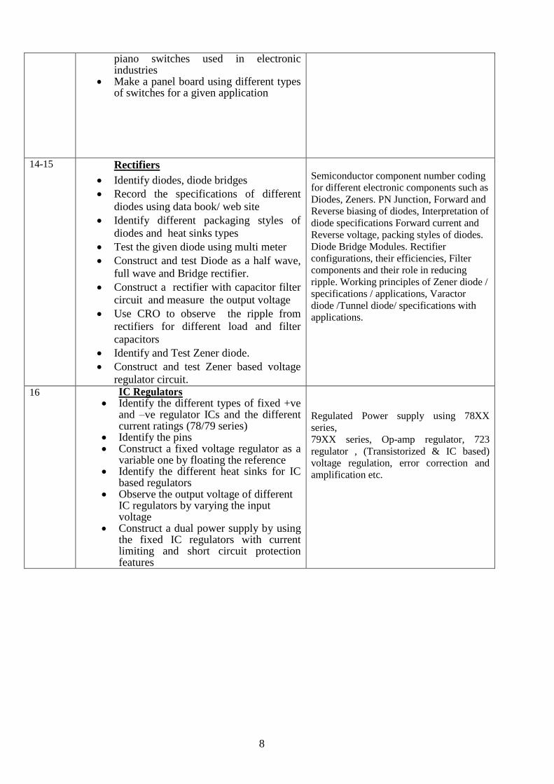
8
piano switches used in electronic industries
Make a panel board using different types of switches for a given application
14-15 Rectifiers
Identify diodes, diode bridges
Record the specifications of different
diodes using data book/ web site
Identify different packaging styles of
diodes and heat sinks types
Test the given diode using multi meter
Construct and test Diode as a half wave,
full wave and Bridge rectifier.
Construct a rectifier with capacitor filter
circuit and measure the output voltage
Use CRO to observe the ripple from
rectifiers for different load and filter
capacitors
Identify and Test Zener diode.
Construct and test Zener based voltage
regulator circuit.
Semiconductor component number coding
for different electronic components such as
Diodes, Zeners. PN Junction, Forward and
Reverse biasing of diodes, Interpretation of
diode specifications Forward current and
Reverse voltage, packing styles of diodes.
Diode Bridge Modules. Rectifier
configurations, their efficiencies, Filter
components and their role in reducing
ripple. Working principles of Zener diode /
specifications / applications, Varactor
diode /Tunnel diode/ specifications with
applications.
16 IC Regulators Identify the different types of fixed +ve
and –ve regulator ICs and the different current ratings (78/79 series)
Identify the pins Construct a fixed voltage regulator as a
variable one by floating the reference Identify the different heat sinks for IC
based regulators Observe the output voltage of different
IC regulators by varying the input voltage
Construct a dual power supply by using the fixed IC regulators with current limiting and short circuit protection features
Regulated Power supply using 78XX
series,
79XX series, Op-amp regulator, 723
regulator , (Transistorized & IC based)
voltage regulation, error correction and
amplification etc.

9
17-21 Computer Hardware, OS, MS office Networking
• Identification of various indicators,
Connectors, ports on the computer cabinet
• Identify drives and their capacity.
• Identify various connectors and cables inside
the cabinet & Identify connections to rear
side and front panel of the cabinet
• Identify various parts of the system unit and
motherboard
• Disable certain functionality by
disconnecting the concerned cables ( like
USB, SERIAL, Flat)
• Replace the CMOS battery
• Replace/Extend a memory module
• Test and Replace the SMPS
• Replace the given HDD on the system
• Replace the given DVD on the system
• Configuring and troubleshooting display
problems
• Boot the system from different options
• Practice various features of OS
• Perform maintenance of the computer using
standard tools provided in the OS
• Install a Printer driver software and test for
print outs
• Install antivirus software and scan the system
and Explore the configuration options in the
antivirus software
• Install MS office software
• Use start menu, check available programs in
computer, use search, settings, run and
options. Creation of short cuts
• Changing screen savers
• Create folder and files, Drawing pictures
using paint, using menus of paint
• Explore different Menu/Tool/ Format/status
bars of MS word and practice the options:
Editing the text, saving the text, changing the
font and size of text.
• Creation of broachers and taking the
printouts
• Practice the Mail merge and Hyperlink
options
• Prepare a power point presentation on any
three known topics with various design
features
• Prepare a power point presentation with
different animation and visual effects.
• Invoke excel sheet from MS WORD and vice
versa
• Convert the given PDF File into WORD File
Basic blocks of a computer, Hardware and
software, I/O devices, keyboard, types of
mouse and their working, Different types
of printers, their function and inter-
connection and their advantages HDD,
CDD, DVD. Various ports in the
computer.
POST Booting concept.
Windows O.S.
MS widows: Starting windows and its
operation, file management using explorer,
Display & sound properties, screen savers,
font management, installation of program,
setting and using of control panel.,
application of accessories, various IT tools
and applications, Components of desk top
Concept of word processing,: MS word
– Menu bar, standard tool bar, saving,
copying, deleting & retrieving files, page
setting, editing, formatting, advance
features i.e. highlighting, cut & paste,
subscript & superscript drawing features,
mail merging, Hyperlink, tables and
borders, printing of document etc.
Excel – Worksheet basics, data entry and
formulae. Moving data in worksheet using
tool bars and menu bars, Formatting and
calculations, printing worksheet, creating
multiple work sheets, creating charts,
changing chart types, Adding titles,
legends and gridlines, colouring charts,
printing charts, placing charts in a word
file.
Introduction to power point Basics of
preparing slides, different design aspects of
slides, animation with slides etc
Concept of Internet, Browsers, Websites,
search engines, email, chatting and
messenger service. Downloading the Data
and program files etc.
Computer Networking:-
Network features-Network topologies,
protocols- TCP/IP, UDP, FTP, models,
types, network components, network
medias,
Specification and standards, types of
cables, UTP, STP, Coaxial cables.
Network components like hub, Ethernet
switch, router, NIC Cards, connectors,
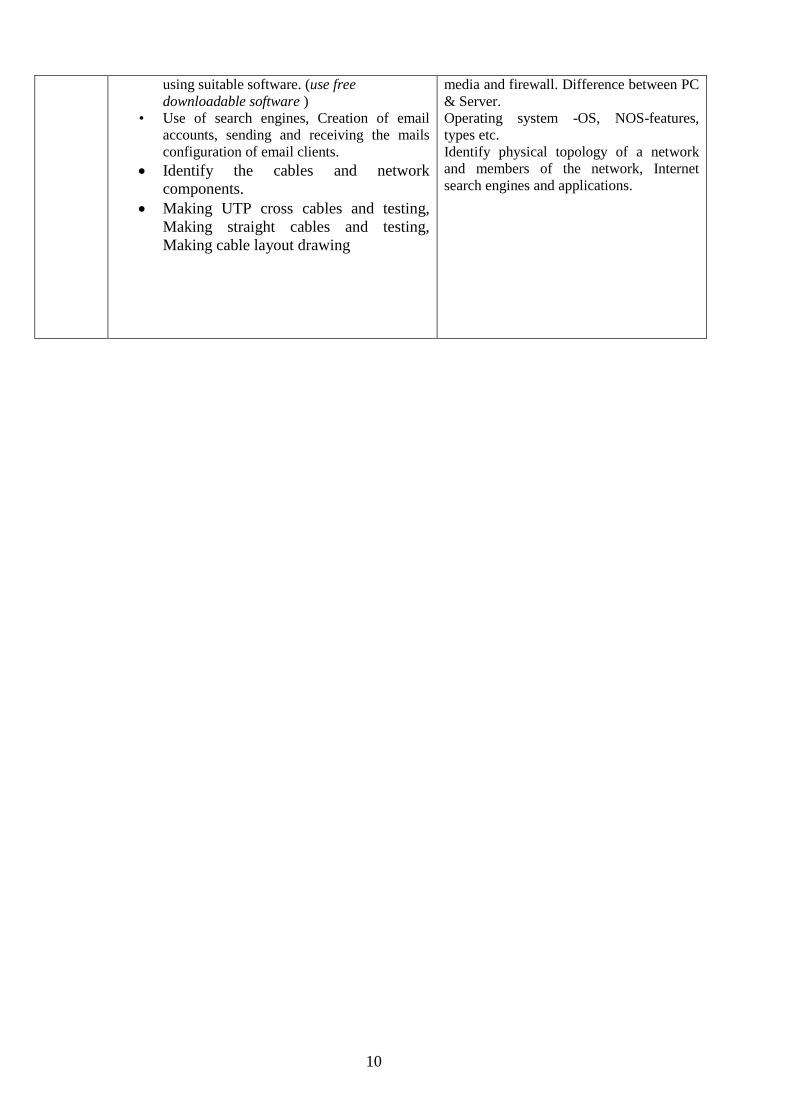
10
using suitable software. (use free
downloadable software )
• Use of search engines, Creation of email
accounts, sending and receiving the mails
configuration of email clients.
Identify the cables and network
components.
Making UTP cross cables and testing,
Making straight cables and testing,
Making cable layout drawing
media and firewall. Difference between PC
& Server.
Operating system -OS, NOS-features,
types etc.
Identify physical topology of a network
and members of the network, Internet
search engines and applications.
11
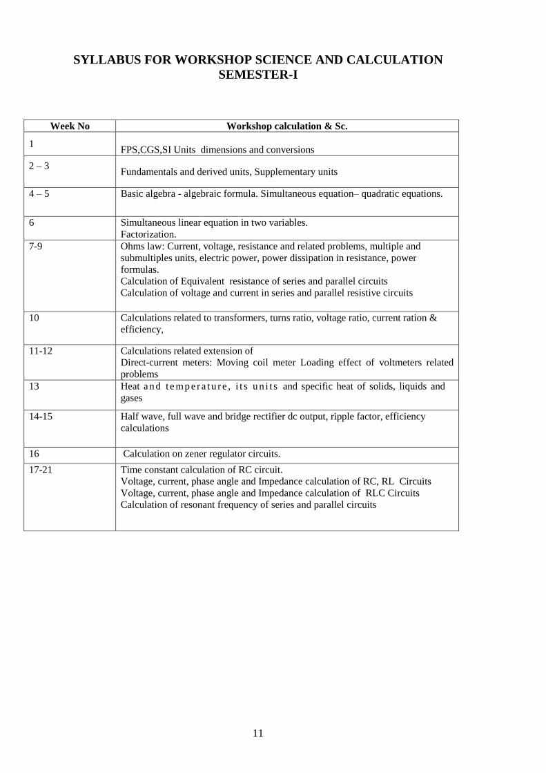
SYLLABUS FOR WORKSHOP SCIENCE AND CALCULATION
SEMESTER-I
Week No Workshop calculation & Sc.
1
FPS,CGS,SI Units dimensions and conversions
2 – 3
Fundamentals and derived units, Supplementary units
4 – 5 Basic algebra - algebraic formula. Simultaneous equation– quadratic equations.
6 Simultaneous linear equation in two variables.
Factorization.
7-9 Ohms law: Current, voltage, resistance and related problems, multiple and
submultiples units, electric power, power dissipation in resistance, power
formulas.
Calculation of Equivalent resistance of series and parallel circuits
Calculation of voltage and current in series and parallel resistive circuits
10 Calculations related to transformers, turns ratio, voltage ratio, current ration &
efficiency,
11-12 Calculations related extension of
Direct-current meters: Moving coil meter Loading effect of voltmeters related
problems
13 Heat an d t e mp era tu r e , i t s u n i t s and specific heat of solids, liquids and
gases
14-15 Half wave, full wave and bridge rectifier dc output, ripple factor, efficiency
calculations
16 Calculation on zener regulator circuits.
17-21 Time constant calculation of RC circuit.
Voltage, current, phase angle and Impedance calculation of RC, RL Circuits
Voltage, current, phase angle and Impedance calculation of RLC Circuits
Calculation of resonant frequency of series and parallel circuits
12
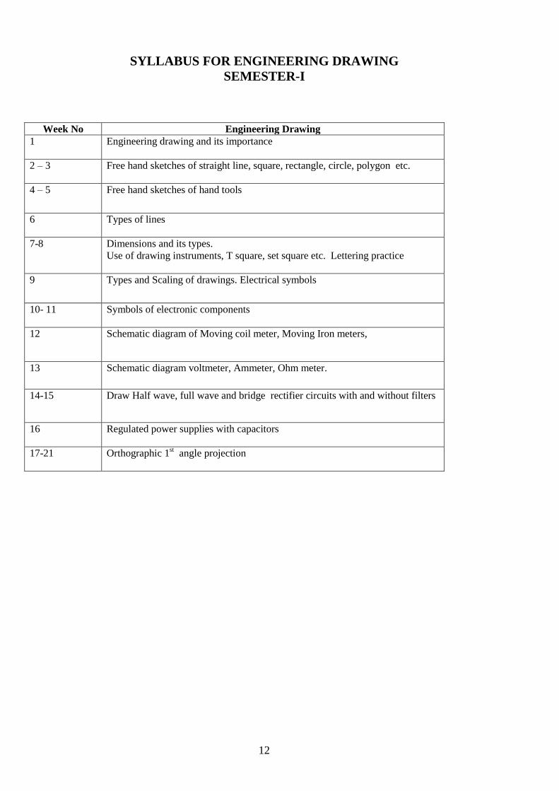
SYLLABUS FOR ENGINEERING DRAWING
SEMESTER-I
Week No Engineering Drawing
1 Engineering drawing and its importance
2 – 3
Free hand sketches of straight line, square, rectangle, circle, polygon etc.
4 – 5 Free hand sketches of hand tools
6 Types of lines
7-8 Dimensions and its types.
Use of drawing instruments, T square, set square etc. Lettering practice
9 Types and Scaling of drawings. Electrical symbols
10- 11 Symbols of electronic components
12 Schematic diagram of Moving coil meter, Moving Iron meters,
13 Schematic diagram voltmeter, Ammeter, Ohm meter.
14-15 Draw Half wave, full wave and bridge rectifier circuits with and without filters
16 Regulated power supplies with capacitors
17-21 Orthographic 1st angle projection

13
Syllabus for the Trade of “Technician Power Electronics Systems”
Duration: 6 Months
Second Semester
Semester Code: PES: SEM II
Analog and Digital Electronic Circuits
OBJECTIVES
Construct and test simple amplifier circuits
Construct and test wave shaping circuits
Identify and test power electronic components
Identify and test opto electronic devices
Practice SMD Soldering and De-soldering of Simple SMD components
Identify and verify truth tables of various digital ICs using Data book
Practice circuit simulation software to simulate and test the circuits
Stimulate and test various circuits using the software
Identify and test various types of LEDs and LED displays
Construct and test various OP-AMP IC based circuits
Construct and test 555 IC based application circuits
14
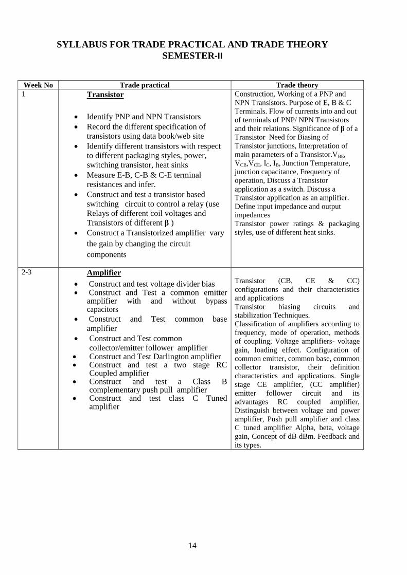
SYLLABUS FOR TRADE PRACTICAL AND TRADE THEORY
SEMESTER-II
Week No Trade practical Trade theory
1 Transistor
Identify PNP and NPN Transistors
Record the different specification of
transistors using data book/web site
Identify different transistors with respect
to different packaging styles, power,
switching transistor, heat sinks
Measure E-B, C-B & C-E terminal
resistances and infer.
Construct and test a transistor based
switching circuit to control a relay (use
Relays of different coil voltages and
Transistors of different β )
Construct a Transistorized amplifier vary
the gain by changing the circuit
components
Construction, Working of a PNP and
NPN Transistors. Purpose of E, B & C
Terminals. Flow of currents into and out
of terminals of PNP/ NPN Transistors
and their relations. Significance of β of a
Transistor Need for Biasing of
Transistor junctions, Interpretation of
main parameters of a Transistor.VBE,
VCB,VCE, IC, IB, Junction Temperature,
junction capacitance, Frequency of
operation, Discuss a Transistor
application as a switch. Discuss a
Transistor application as an amplifier.
Define input impedance and output
impedances
Transistor power ratings & packaging
styles, use of different heat sinks.
2-3 Amplifier
Construct and test voltage divider bias Construct and Test a common emitter
amplifier with and without bypass capacitors
Construct and Test common base
amplifier
Construct and Test common
collector/emitter follower amplifier Construct and Test Darlington amplifier Construct and test a two stage RC
Coupled amplifier Construct and test a Class B
complementary push pull amplifier Construct and test class C Tuned
amplifier
Transistor (CB, CE & CC)
configurations and their characteristics
and applications
Transistor biasing circuits and
stabilization Techniques.
Classification of amplifiers according to
frequency, mode of operation, methods
of coupling, Voltage amplifiers- voltage
gain, loading effect. Configuration of
common emitter, common base, common
collector transistor, their definition
characteristics and applications. Single
stage CE amplifier, (CC amplifier)
emitter follower circuit and its
advantages RC coupled amplifier,
Distinguish between voltage and power
amplifier, Push pull amplifier and class
C tuned amplifier Alpha, beta, voltage
gain, Concept of dB dBm. Feedback and
its types.
15
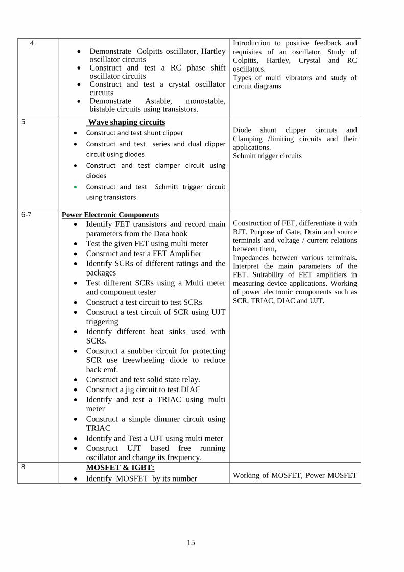
4 Demonstrate Colpitts oscillator, Hartley
oscillator circuits Construct and test a RC phase shift
oscillator circuits Construct and test a crystal oscillator
circuits Demonstrate Astable, monostable,
bistable circuits using transistors.
Introduction to positive feedback and
requisites of an oscillator, Study of
Colpitts, Hartley, Crystal and RC
oscillators.
Types of multi vibrators and study of
circuit diagrams
5 Wave shaping circuits
Construct and test shunt clipper
Construct and test series and dual clipper
circuit using diodes
Construct and test clamper circuit using
diodes
Construct and test Schmitt trigger circuit
using transistors
Diode shunt clipper circuits and
Clamping /limiting circuits and their
applications.
Schmitt trigger circuits
6-7 Power Electronic Components
Identify FET transistors and record main
parameters from the Data book
Test the given FET using multi meter
Construct and test a FET Amplifier
Identify SCRs of different ratings and the
packages
Test different SCRs using a Multi meter
and component tester
Construct a test circuit to test SCRs
Construct a test circuit of SCR using UJT
triggering
Identify different heat sinks used with
SCRs.
Construct a snubber circuit for protecting
SCR use freewheeling diode to reduce
back emf.
Construct and test solid state relay.
Construct a jig circuit to test DIAC
Identify and test a TRIAC using multi
meter
Construct a simple dimmer circuit using
TRIAC
Identify and Test a UJT using multi meter
Construct UJT based free running
oscillator and change its frequency.
Construction of FET, differentiate it with
BJT. Purpose of Gate, Drain and source
terminals and voltage / current relations
between them,
Impedances between various terminals.
Interpret the main parameters of the
FET. Suitability of FET amplifiers in
measuring device applications. Working
of power electronic components such as
SCR, TRIAC, DIAC and UJT.
8 MOSFET & IGBT:
Identify MOSFET by its number
Working of MOSFET, Power MOSFET
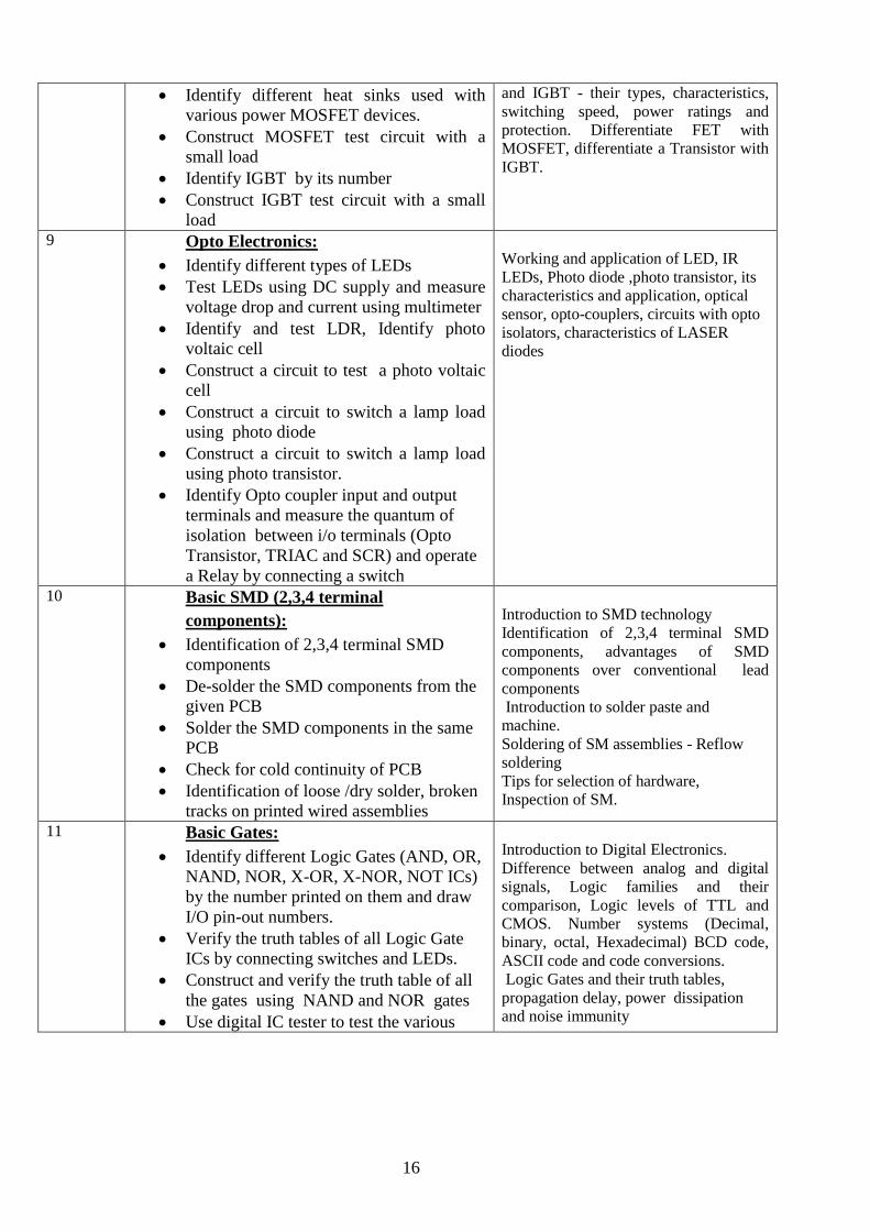
16
Identify different heat sinks used with
various power MOSFET devices.
Construct MOSFET test circuit with a
small load
Identify IGBT by its number
Construct IGBT test circuit with a small
load
and IGBT - their types, characteristics,
switching speed, power ratings and
protection. Differentiate FET with
MOSFET, differentiate a Transistor with
IGBT.
9 Opto Electronics:
Identify different types of LEDs
Test LEDs using DC supply and measure
voltage drop and current using multimeter
Identify and test LDR, Identify photo
voltaic cell
Construct a circuit to test a photo voltaic
cell
Construct a circuit to switch a lamp load
using photo diode
Construct a circuit to switch a lamp load
using photo transistor.
Identify Opto coupler input and output
terminals and measure the quantum of
isolation between i/o terminals (Opto
Transistor, TRIAC and SCR) and operate
a Relay by connecting a switch
Working and application of LED, IR
LEDs, Photo diode ,photo transistor, its
characteristics and application, optical
sensor, opto-couplers, circuits with opto
isolators, characteristics of LASER
diodes
10 Basic SMD (2,3,4 terminal
components):
Identification of 2,3,4 terminal SMD
components
De-solder the SMD components from the
given PCB
Solder the SMD components in the same
PCB
Check for cold continuity of PCB
Identification of loose /dry solder, broken
tracks on printed wired assemblies
Introduction to SMD technology
Identification of 2,3,4 terminal SMD
components, advantages of SMD
components over conventional lead
components
Introduction to solder paste and
machine.
Soldering of SM assemblies - Reflow
soldering
Tips for selection of hardware,
Inspection of SM.
11 Basic Gates:
Identify different Logic Gates (AND, OR,
NAND, NOR, X-OR, X-NOR, NOT ICs)
by the number printed on them and draw
I/O pin-out numbers.
Verify the truth tables of all Logic Gate
ICs by connecting switches and LEDs.
Construct and verify the truth table of all
the gates using NAND and NOR gates
Use digital IC tester to test the various
Introduction to Digital Electronics.
Difference between analog and digital
signals, Logic families and their
comparison, Logic levels of TTL and
CMOS. Number systems (Decimal,
binary, octal, Hexadecimal) BCD code,
ASCII code and code conversions.
Logic Gates and their truth tables,
propagation delay, power dissipation
and noise immunity
17
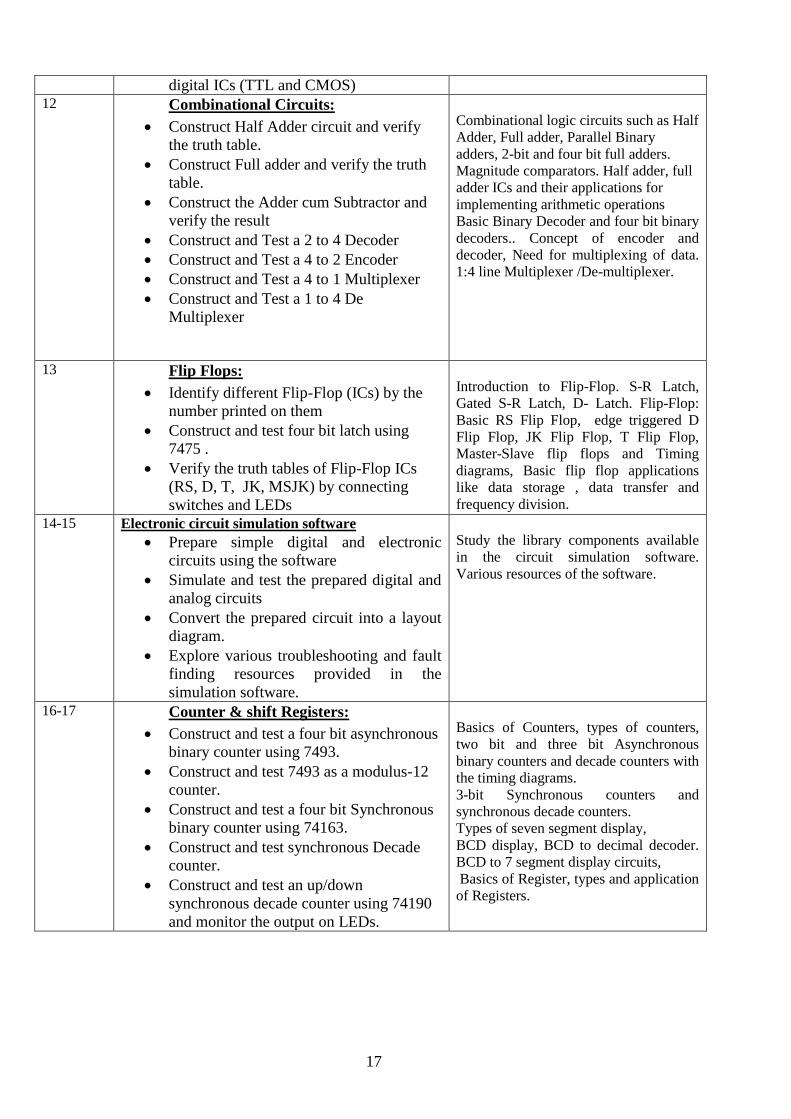
digital ICs (TTL and CMOS) 12 Combinational Circuits:
Construct Half Adder circuit and verify
the truth table.
Construct Full adder and verify the truth
table.
Construct the Adder cum Subtractor and
verify the result
Construct and Test a 2 to 4 Decoder
Construct and Test a 4 to 2 Encoder
Construct and Test a 4 to 1 Multiplexer
Construct and Test a 1 to 4 De
Multiplexer
Combinational logic circuits such as Half
Adder, Full adder, Parallel Binary
adders, 2-bit and four bit full adders.
Magnitude comparators. Half adder, full
adder ICs and their applications for
implementing arithmetic operations
Basic Binary Decoder and four bit binary
decoders.. Concept of encoder and
decoder, Need for multiplexing of data.
1:4 line Multiplexer /De-multiplexer.
13 Flip Flops:
Identify different Flip-Flop (ICs) by the
number printed on them
Construct and test four bit latch using
7475 .
Verify the truth tables of Flip-Flop ICs
(RS, D, T, JK, MSJK) by connecting
switches and LEDs
Introduction to Flip-Flop. S-R Latch,
Gated S-R Latch, D- Latch. Flip-Flop:
Basic RS Flip Flop, edge triggered D
Flip Flop, JK Flip Flop, T Flip Flop,
Master-Slave flip flops and Timing
diagrams, Basic flip flop applications
like data storage , data transfer and
frequency division.
14-15 Electronic circuit simulation software
Prepare simple digital and electronic
circuits using the software
Simulate and test the prepared digital and
analog circuits
Convert the prepared circuit into a layout
diagram.
Explore various troubleshooting and fault
finding resources provided in the
simulation software.
Study the library components available
in the circuit simulation software.
Various resources of the software.
16-17 Counter & shift Registers:
Construct and test a four bit asynchronous
binary counter using 7493.
Construct and test 7493 as a modulus-12
counter.
Construct and test a four bit Synchronous
binary counter using 74163.
Construct and test synchronous Decade
counter.
Construct and test an up/down
synchronous decade counter using 74190
and monitor the output on LEDs.
Basics of Counters, types of counters,
two bit and three bit Asynchronous
binary counters and decade counters with
the timing diagrams.
3-bit Synchronous counters and
synchronous decade counters.
Types of seven segment display,
BCD display, BCD to decimal decoder.
BCD to 7 segment display circuits,
Basics of Register, types and application
of Registers.
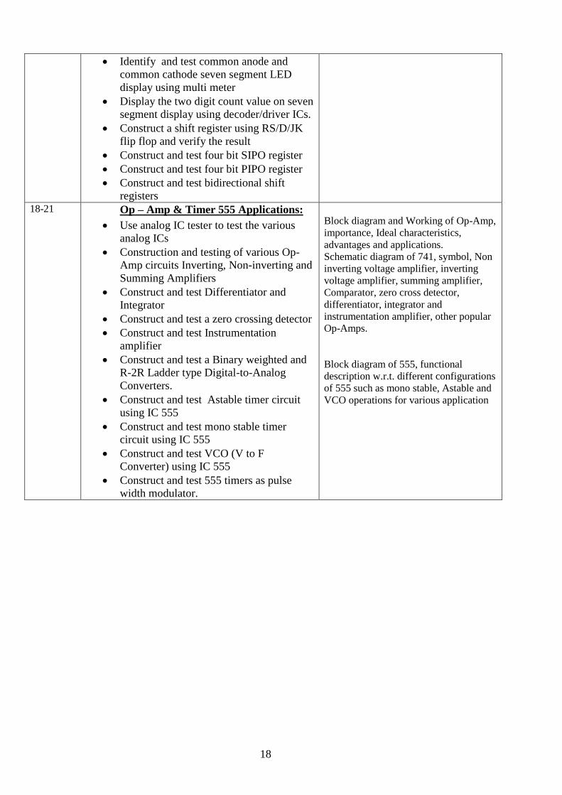
18
Identify and test common anode and
common cathode seven segment LED
display using multi meter
Display the two digit count value on seven
segment display using decoder/driver ICs.
Construct a shift register using RS/D/JK
flip flop and verify the result
Construct and test four bit SIPO register
Construct and test four bit PIPO register
Construct and test bidirectional shift
registers 18-21 Op – Amp & Timer 555 Applications:
Use analog IC tester to test the various
analog ICs
Construction and testing of various Op-
Amp circuits Inverting, Non-inverting and
Summing Amplifiers
Construct and test Differentiator and
Integrator
Construct and test a zero crossing detector
Construct and test Instrumentation
amplifier
Construct and test a Binary weighted and
R-2R Ladder type Digital-to-Analog
Converters.
Construct and test Astable timer circuit
using IC 555
Construct and test mono stable timer
circuit using IC 555
Construct and test VCO (V to F
Converter) using IC 555
Construct and test 555 timers as pulse
width modulator.
Block diagram and Working of Op-Amp,
importance, Ideal characteristics,
advantages and applications.
Schematic diagram of 741, symbol, Non
inverting voltage amplifier, inverting
voltage amplifier, summing amplifier,
Comparator, zero cross detector,
differentiator, integrator and
instrumentation amplifier, other popular
Op-Amps.
Block diagram of 555, functional
description w.r.t. different configurations
of 555 such as mono stable, Astable and
VCO operations for various application
19
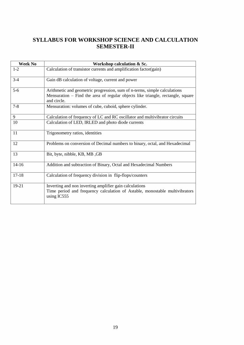
SYLLABUS FOR WORKSHOP SCIENCE AND CALCULATION
SEMESTER-II
Week No Workshop calculation & Sc.
1-2 Calculation of transistor currents and amplification factor(gain)
3-4 Gain dB calculation of voltage, current and power
5-6 Arithmetic and geometric progression, sum of n-terms, simple calculations
Mensuration – Find the area of regular objects like triangle, rectangle, square
and circle.
7-8 Mensuration: volumes of cube, cuboid, sphere cylinder.
9 Calculation of frequency of LC and RC oscillator and multivibrator circuits
10 Calculation of LED, IRLED and photo diode currents
11 Trigonometry ratios, identities
12 Problems on conversion of Decimal numbers to binary, octal, and Hexadecimal
13 Bit, byte, nibble, KB, MB ,GB
14-16 Addition and subtraction of Binary, Octal and Hexadecimal Numbers
17-18 Calculation of frequency division in flip-flops/counters
19-21 Inverting and non inverting amplifier gain calculations
Time period and frequency calculation of Astable, monostable multivibrators
using IC555
20
SYLLABUS FOR ENGINEERING DRAWING
SEMESTER-II
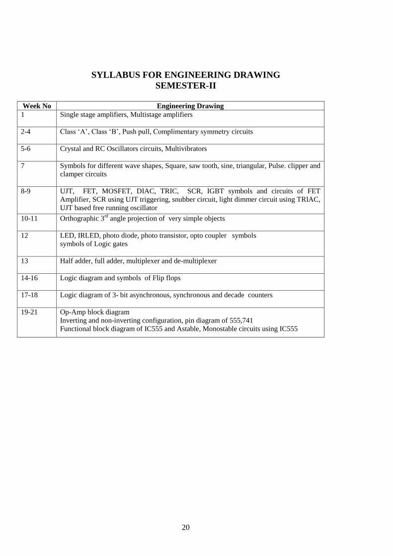
Week No Engineering Drawing
1 Single stage amplifiers, Multistage amplifiers
2-4 Class ‘A’, Class ‘B’, Push pull, Complimentary symmetry circuits
5-6 Crystal and RC Oscillators circuits, Multivibrators
7 Symbols for different wave shapes, Square, saw tooth, sine, triangular, Pulse. clipper and
clamper circuits
8-9 UJT, FET, MOSFET, DIAC, TRIC, SCR, IGBT symbols and circuits of FET
Amplifier, SCR using UJT triggering, snubber circuit, light dimmer circuit using TRIAC,
UJT based free running oscillator
10-11 Orthographic 3rd
angle projection of very simple objects
12 LED, IRLED, photo diode, photo transistor, opto coupler symbols
symbols of Logic gates
13 Half adder, full adder, multiplexer and de-multiplexer
14-16 Logic diagram and symbols of Flip flops
17-18 Logic diagram of 3- bit asynchronous, synchronous and decade counters
19-21 Op-Amp block diagram
Inverting and non-inverting configuration, pin diagram of 555,741
Functional block diagram of IC555 and Astable, Monostable circuits using IC555

21
A. Tools & Equipments for the trade of Technician Power Electronics Systems for First and
Second Semester
TRAINEES TOOL KIT FOR 20 TRAINEES +1 INSTRUCTOR
Sl
No. Names of the Items Quantity
1. Connecting screwdriver 100 mm 10 Nos
2. Neon tester 500 V. 6 Nos
3. Screw driver set (set of 5 ) 10 Nos
4. Insulated combination pliers 150 mm 6 Nos
5. Insulated side cutting pliers 150 mm 8 Nos
6. Long nose pliers 150 mm 6 Nos
7. Soldering iron 25 W. 240 V. 10 Nos
8. Electrician knife 6 Nos
9. Tweezers 100mm 10 Nos
10. Digital Multimeter (3 ½ digit) 10 Nos
11. Soldering Iron Changeable bits 10 W 6 Nos
12. De- soldering pump 10 Nos
B. General Machinery Shop outfit
Sl.No Name of the items Quantity
1. Steel rule 300mm 4 Nos
2. Steel measuring tape-3 m 4 Nos
3. Tools makers vice 100mm (clamp) 1 Nos
4. Tools maker vice 50mm (clamp) 1 Nos
5. Crimping tool (pliers) 2 Nos
6. Magneto spanner set 2 Nos
7. File flat 200mm bastard 2 Nos
8. File flat 200mm second cut 2 Nos
9. File flat 200mm smooth 2Nos
10. 100mm flat pliers 4 Nos
11. 100mm round Nose pliers 4 Nos
12. Scriber straight 150mm 2 Nos
13. Hammer ball pen 0.5Kg 1 No
14. Allen key set (set of 9) 1 No
15. Tubular box spanner (set of 6Nos) 1 set
16. Magnifying lenses 75mm 2 Nos
17. Continuity tester 6 Nos
18. Hacksaw frame adjustable 2 Nos
19. Cold chisel 20mm 1 No
20. Scissors 200mm 1 No
21. Handsaw 450mm 1 No
22. Hand Drill Machine 2 Nos
23. First aid kit 1 No
22
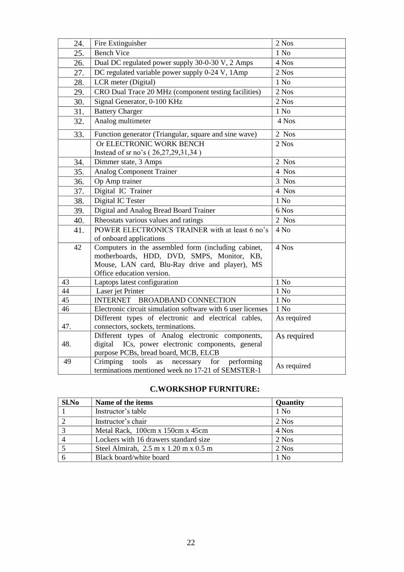
24. Fire Extinguisher 2 Nos
25. Bench Vice 1 No
26. Dual DC regulated power supply 30-0-30 V, 2 Amps 4 Nos
27. DC regulated variable power supply 0-24 V, 1Amp 2 Nos
28. LCR meter (Digital) 1 No
29. CRO Dual Trace 20 MHz (component testing facilities) 2 Nos
30. Signal Generator, 0-100 KHz 2 Nos
31. Battery Charger 1 No
32. Analog multimeter 4 Nos
33. Function generator (Triangular, square and sine wave) 2 Nos
Or ELECTRONIC WORK BENCH
Instead of sr no’s ( 26,27,29,31,34 )
2 Nos
34. Dimmer state, 3 Amps 2 Nos
35. Analog Component Trainer 4 Nos
36. Op Amp trainer 3 Nos
37. Digital IC Trainer 4 Nos
38. Digital IC Tester 1 No
39. Digital and Analog Bread Board Trainer 6 Nos
40. Rheostats various values and ratings 2 Nos
41. POWER ELECTRONICS TRAINER with at least 6 no’s
of onboard applications
4 No
42 Computers in the assembled form (including cabinet,
motherboards, HDD, DVD, SMPS, Monitor, KB,
Mouse, LAN card, Blu-Ray drive and player), MS
Office education version.
4 Nos
43 Laptops latest configuration 1 No
44 Laser jet Printer 1 No
45 INTERNET BROADBAND CONNECTION 1 No
46 Electronic circuit simulation software with 6 user licenses 1 No
47.
Different types of electronic and electrical cables,
connectors, sockets, terminations.
As required
48.
Different types of Analog electronic components,
digital ICs, power electronic components, general
purpose PCBs, bread board, MCB, ELCB
As required
49 Crimping tools as necessary for performing
terminations mentioned week no 17-21 of SEMSTER-1 As required
C.WORKSHOP FURNITURE:
Sl.No Name of the items Quantity
1 Instructor’s table 1 No
2 Instructor’s chair 2 Nos
3 Metal Rack, 100cm x 150cm x 45cm 4 Nos
4 Lockers with 16 drawers standard size 2 Nos
5 Steel Almirah, 2.5 m x 1.20 m x 0.5 m 2 Nos
6 Black board/white board 1 No
23
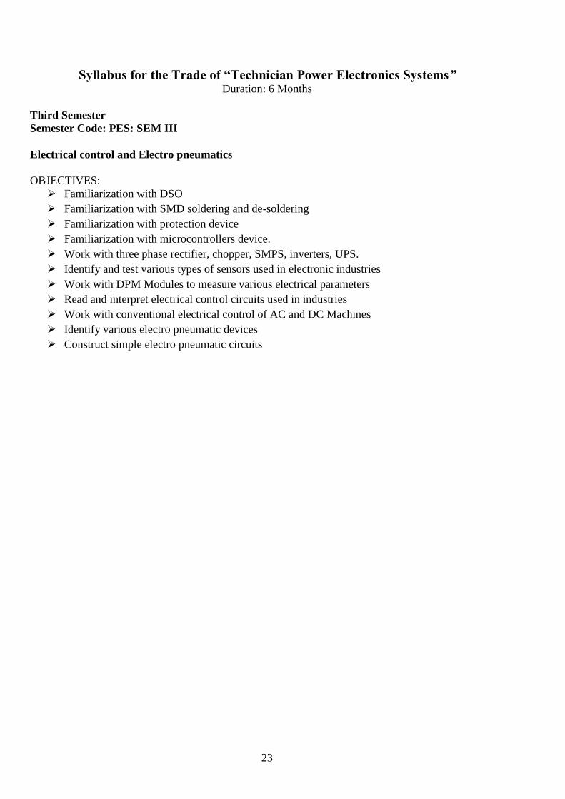
Syllabus for the Trade of “Technician Power Electronics Systems” Duration: 6 Months
Third Semester
Semester Code: PES: SEM III
Electrical control and Electro pneumatics
OBJECTIVES:
Familiarization with DSO
Familiarization with SMD soldering and de-soldering
Familiarization with protection device
Familiarization with microcontrollers device.
Work with three phase rectifier, chopper, SMPS, inverters, UPS.
Identify and test various types of sensors used in electronic industries
Work with DPM Modules to measure various electrical parameters
Read and interpret electrical control circuits used in industries
Work with conventional electrical control of AC and DC Machines
Identify various electro pneumatic devices
Construct simple electro pneumatic circuits
24
SYLLABUS FOR TRADE PRACTICAL AND TRADE THEORY
SEMESTER-III
Week
No.
Practical Theory
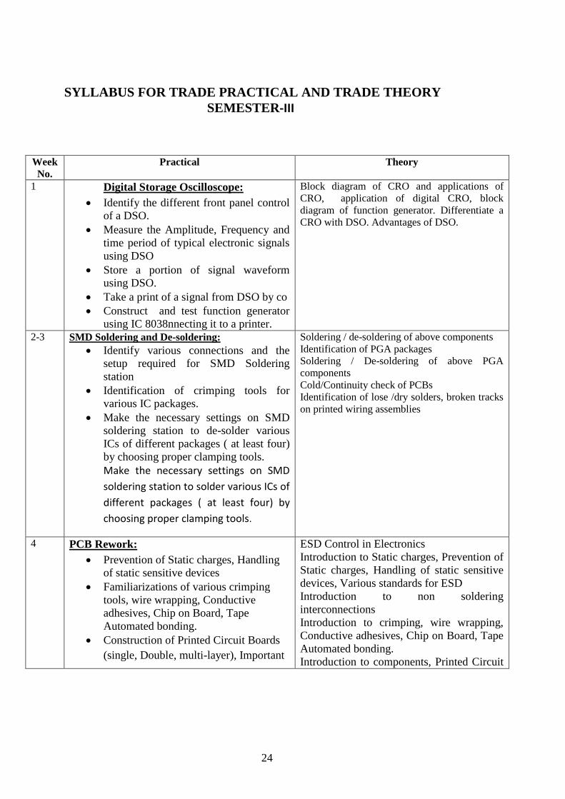
1
Digital Storage Oscilloscope:
Identify the different front panel control
of a DSO.
Measure the Amplitude, Frequency and
time period of typical electronic signals
using DSO
Store a portion of signal waveform
using DSO.
Take a print of a signal from DSO by co
Construct and test function generator
using IC 8038nnecting it to a printer.
Block diagram of CRO and applications of
CRO, application of digital CRO, block
diagram of function generator. Differentiate a
CRO with DSO. Advantages of DSO.
2-3 SMD Soldering and De-soldering:
Identify various connections and the
setup required for SMD Soldering
station
Identification of crimping tools for
various IC packages.
Make the necessary settings on SMD
soldering station to de-solder various
ICs of different packages ( at least four)
by choosing proper clamping tools.
Make the necessary settings on SMD
soldering station to solder various ICs of
different packages ( at least four) by
choosing proper clamping tools.
Soldering / de-soldering of above components
Identification of PGA packages
Soldering / De-soldering of above PGA
components
Cold/Continuity check of PCBs
Identification of lose /dry solders, broken tracks
on printed wiring assemblies
4 PCB Rework:
Prevention of Static charges, Handling
of static sensitive devices
Familiarizations of various crimping
tools, wire wrapping, Conductive
adhesives, Chip on Board, Tape
Automated bonding.
Construction of Printed Circuit Boards
(single, Double, multi-layer), Important
ESD Control in Electronics
Introduction to Static charges, Prevention of
Static charges, Handling of static sensitive
devices, Various standards for ESD
Introduction to non soldering
interconnections
Introduction to crimping, wire wrapping,
Conductive adhesives, Chip on Board, Tape
Automated bonding.
Introduction to components, Printed Circuit
25
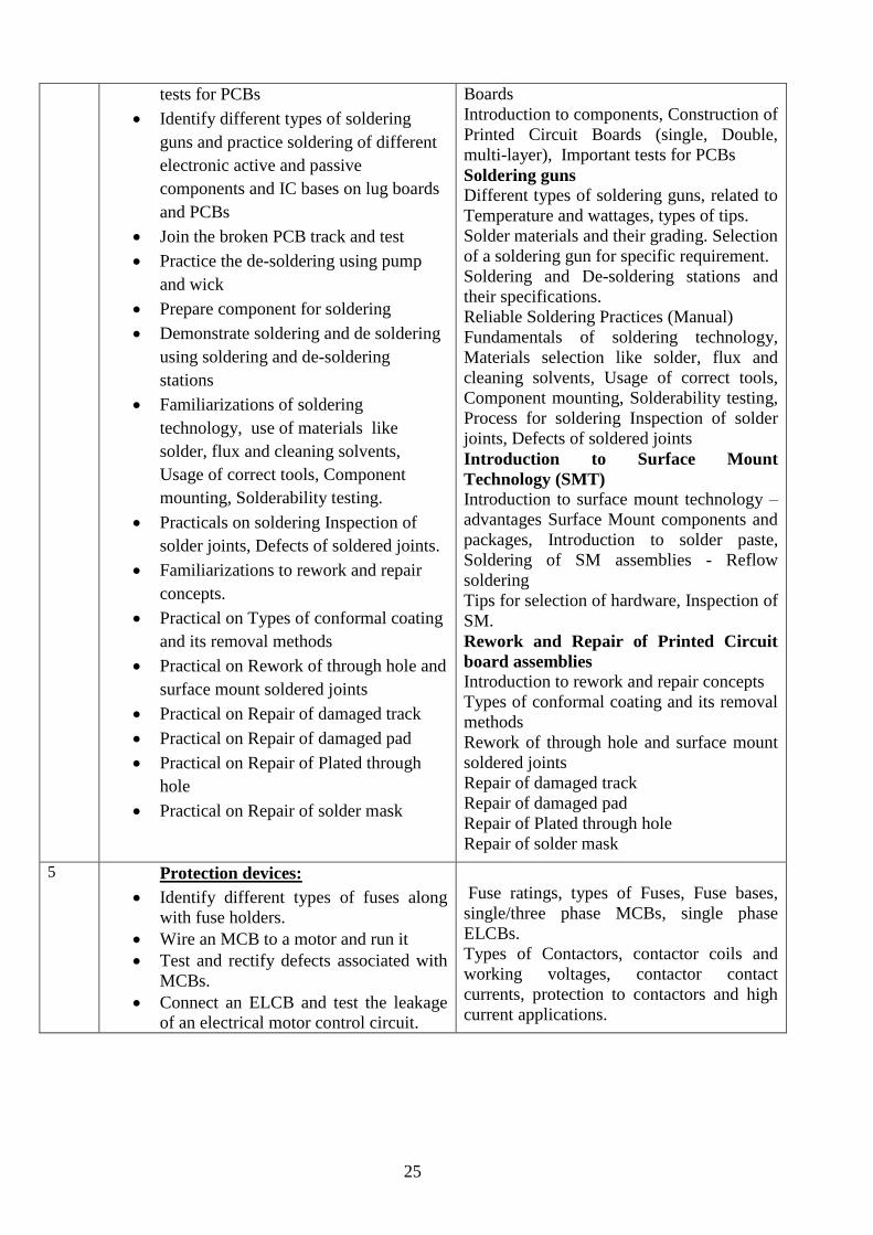
tests for PCBs
Identify different types of soldering
guns and practice soldering of different
electronic active and passive
components and IC bases on lug boards
and PCBs
Join the broken PCB track and test
Practice the de-soldering using pump
and wick
Prepare component for soldering
Demonstrate soldering and de soldering
using soldering and de-soldering
stations
Familiarizations of soldering
technology, use of materials like
solder, flux and cleaning solvents,
Usage of correct tools, Component
mounting, Solderability testing.
Practicals on soldering Inspection of
solder joints, Defects of soldered joints.
Familiarizations to rework and repair
concepts.
Practical on Types of conformal coating
and its removal methods
Practical on Rework of through hole and
surface mount soldered joints
Practical on Repair of damaged track
Practical on Repair of damaged pad
Practical on Repair of Plated through
hole
Practical on Repair of solder mask
Boards
Introduction to components, Construction of
Printed Circuit Boards (single, Double,
multi-layer), Important tests for PCBs
Soldering guns
Different types of soldering guns, related to
Temperature and wattages, types of tips.
Solder materials and their grading. Selection
of a soldering gun for specific requirement.
Soldering and De-soldering stations and
their specifications.
Reliable Soldering Practices (Manual)
Fundamentals of soldering technology,
Materials selection like solder, flux and
cleaning solvents, Usage of correct tools,
Component mounting, Solderability testing,
Process for soldering Inspection of solder
joints, Defects of soldered joints
Introduction to Surface Mount
Technology (SMT)
Introduction to surface mount technology –
advantages Surface Mount components and
packages, Introduction to solder paste,
Soldering of SM assemblies - Reflow
soldering
Tips for selection of hardware, Inspection of
SM.
Rework and Repair of Printed Circuit
board assemblies
Introduction to rework and repair concepts
Types of conformal coating and its removal
methods
Rework of through hole and surface mount
soldered joints
Repair of damaged track
Repair of damaged pad
Repair of Plated through hole
Repair of solder mask
5 Protection devices:
Identify different types of fuses along
with fuse holders.
Wire an MCB to a motor and run it
Test and rectify defects associated with
MCBs.
Connect an ELCB and test the leakage
of an electrical motor control circuit.
Fuse ratings, types of Fuses, Fuse bases,
single/three phase MCBs, single phase
ELCBs.
Types of Contactors, contactor coils and
working voltages, contactor contact
currents, protection to contactors and high
current applications.
26
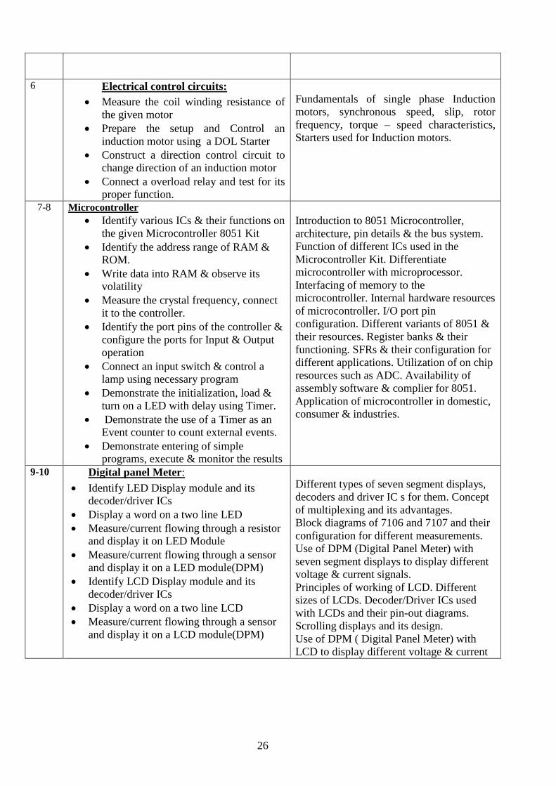
6 Electrical control circuits:
Measure the coil winding resistance of
the given motor
Prepare the setup and Control an
induction motor using a DOL Starter
Construct a direction control circuit to
change direction of an induction motor
Connect a overload relay and test for its
proper function.
Fundamentals of single phase Induction
motors, synchronous speed, slip, rotor
frequency, torque – speed characteristics,
Starters used for Induction motors.
7-8 Microcontroller
Identify various ICs & their functions on
the given Microcontroller 8051 Kit
Identify the address range of RAM &
ROM.
Write data into RAM & observe its
volatility
Measure the crystal frequency, connect
it to the controller.
Identify the port pins of the controller &
configure the ports for Input & Output
operation
Connect an input switch & control a
lamp using necessary program
Demonstrate the initialization, load &
turn on a LED with delay using Timer.
Demonstrate the use of a Timer as an
Event counter to count external events.
Demonstrate entering of simple
programs, execute & monitor the results
Introduction to 8051 Microcontroller,
architecture, pin details & the bus system.
Function of different ICs used in the
Microcontroller Kit. Differentiate
microcontroller with microprocessor.
Interfacing of memory to the
microcontroller. Internal hardware resources
of microcontroller. I/O port pin
configuration. Different variants of 8051 &
their resources. Register banks & their
functioning. SFRs & their configuration for
different applications. Utilization of on chip
resources such as ADC. Availability of
assembly software & complier for 8051.
Application of microcontroller in domestic,
consumer & industries.
9-10 Digital panel Meter:
Identify LED Display module and its
decoder/driver ICs
Display a word on a two line LED
Measure/current flowing through a resistor
and display it on LED Module
Measure/current flowing through a sensor
and display it on a LED module(DPM)
Identify LCD Display module and its
decoder/driver ICs
Display a word on a two line LCD
Measure/current flowing through a sensor
and display it on a LCD module(DPM)
Different types of seven segment displays,
decoders and driver IC s for them. Concept
of multiplexing and its advantages.
Block diagrams of 7106 and 7107 and their
configuration for different measurements.
Use of DPM (Digital Panel Meter) with
seven segment displays to display different
voltage & current signals.
Principles of working of LCD. Different
sizes of LCDs. Decoder/Driver ICs used
with LCDs and their pin-out diagrams.
Scrolling displays and its design.
Use of DPM ( Digital Panel Meter) with
LCD to display different voltage & current
27
signals
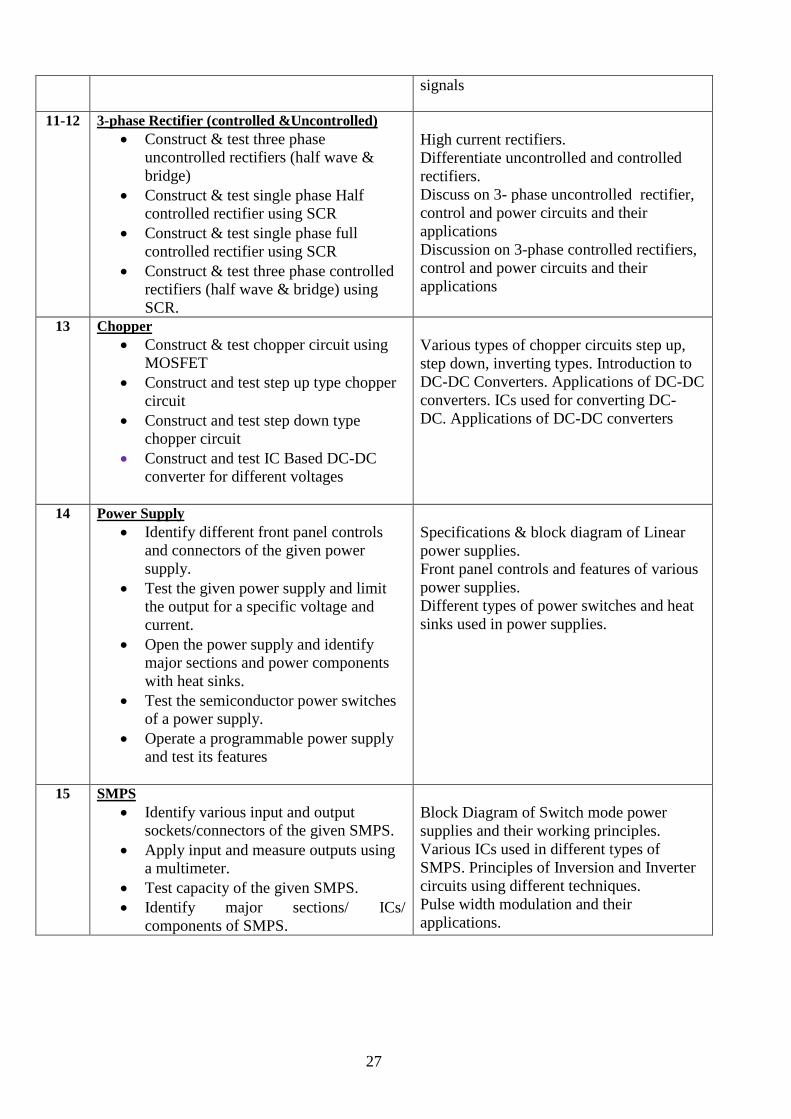
11-12 3-phase Rectifier (controlled &Uncontrolled)
Construct & test three phase
uncontrolled rectifiers (half wave &
bridge)
Construct & test single phase Half
controlled rectifier using SCR
Construct & test single phase full
controlled rectifier using SCR
Construct & test three phase controlled
rectifiers (half wave & bridge) using
SCR.
High current rectifiers.
Differentiate uncontrolled and controlled
rectifiers.
Discuss on 3- phase uncontrolled rectifier,
control and power circuits and their
applications
Discussion on 3-phase controlled rectifiers,
control and power circuits and their
applications
13 Chopper
Construct & test chopper circuit using
MOSFET
Construct and test step up type chopper
circuit
Construct and test step down type
chopper circuit
Construct and test IC Based DC-DC
converter for different voltages
Various types of chopper circuits step up,
step down, inverting types. Introduction to
DC-DC Converters. Applications of DC-DC
converters. ICs used for converting DC-
DC. Applications of DC-DC converters
14 Power Supply
Identify different front panel controls
and connectors of the given power
supply.
Test the given power supply and limit
the output for a specific voltage and
current.
Open the power supply and identify
major sections and power components
with heat sinks.
Test the semiconductor power switches
of a power supply.
Operate a programmable power supply
and test its features
Specifications & block diagram of Linear
power supplies.
Front panel controls and features of various
power supplies.
Different types of power switches and heat
sinks used in power supplies.
15 SMPS
Identify various input and output
sockets/connectors of the given SMPS.
Apply input and measure outputs using
a multimeter.
Test capacity of the given SMPS.
Identify major sections/ ICs/
components of SMPS.
Block Diagram of Switch mode power
supplies and their working principles.
Various ICs used in different types of
SMPS. Principles of Inversion and Inverter
circuits using different techniques.
Pulse width modulation and their
applications.
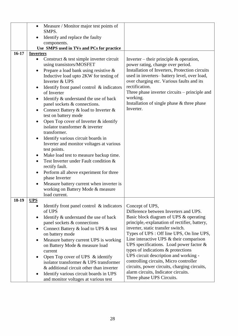
28
Measure / Monitor major test points of
SMPS.
Identify and replace the faulty
components. Use SMPS used in TVs and PCs for practice
16-17 Inverters
Construct & test simple inverter circuit
using transistors/MOSFET
Prepare a load bank using resistive &
Inductive load upto 2KW for testing of
Inverter & UPS
Identify front panel control & indicators
of Inverter
Identify & understand the use of back
panel sockets & connections.
Connect Battery & load to Inverter &
test on battery mode
Open Top cover of Inverter & identify
isolator transformer & inverter
transformer.
Identify various circuit boards in
Inverter and monitor voltages at various
test points.
Make load test to measure backup time.
Test Inverter under Fault condition &
rectify fault.
Perform all above experiment for three
phase Inverter
Measure battery current when inverter is
working on Battery Mode & measure
load current.
Inverter – their principle & operation,
power rating, change over period.
Installation of Inverters, Protection circuits
used in inverters– battery level, over load,
over charging etc. Various faults and its
rectification.
Three phase inverter circuits – principle and
working.
Installation of single phase & three phase
Inverter.
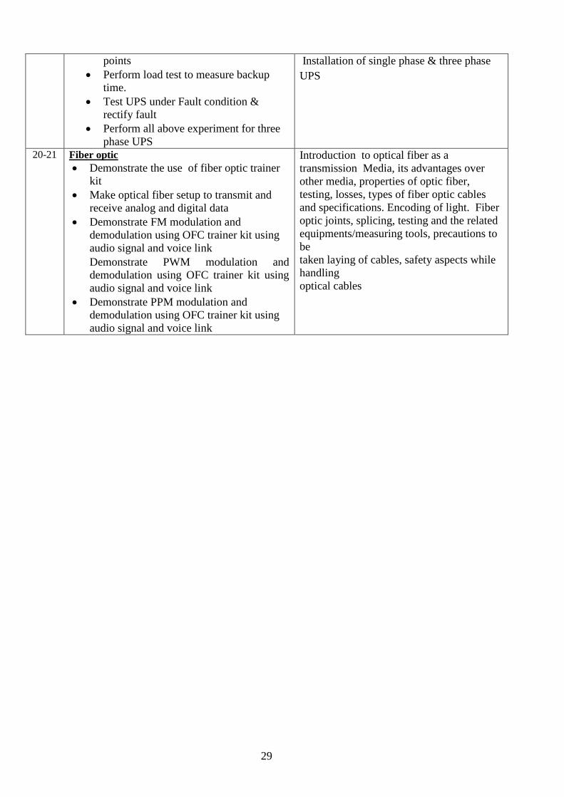
18-19 UPS
Identify front panel control & indicators
of UPS
Identify & understand the use of back
panel sockets & connections
Connect Battery & load to UPS & test
on battery mode
Measure battery current UPS is working
on Battery Mode & measure load
current
Open Top cover of UPS & identify
isolator transformer & UPS transformer
& additional circuit other than inverter
Identify various circuit boards in UPS
and monitor voltages at various test
Concept of UPS,
Difference between Inverters and UPS.
Basic block diagram of UPS & operating
principle,-explanation of rectifier, battery,
inverter, static transfer switch.
Types of UPS : Off line UPS, On line UPS,
Line interactive UPS & their comparison
UPS specifications. Load power factor &
types of indications & protections
UPS circuit description and working -
controlling circuits, Micro controller
circuits, power circuits, charging circuits,
alarm circuits, Indicator circuits.
Three phase UPS Circuits.
29
points
Perform load test to measure backup
time.
Test UPS under Fault condition &
rectify fault
Perform all above experiment for three
phase UPS
Installation of single phase & three phase
UPS
20-21 Fiber optic
Demonstrate the use of fiber optic trainer
kit
Make optical fiber setup to transmit and
receive analog and digital data
Demonstrate FM modulation and
demodulation using OFC trainer kit using
audio signal and voice link
Demonstrate PWM modulation and
demodulation using OFC trainer kit using
audio signal and voice link
Demonstrate PPM modulation and
demodulation using OFC trainer kit using
audio signal and voice link
Introduction to optical fiber as a
transmission Media, its advantages over
other media, properties of optic fiber,
testing, losses, types of fiber optic cables
and specifications. Encoding of light. Fiber
optic joints, splicing, testing and the related
equipments/measuring tools, precautions to
be
taken laying of cables, safety aspects while
handling
optical cables
30
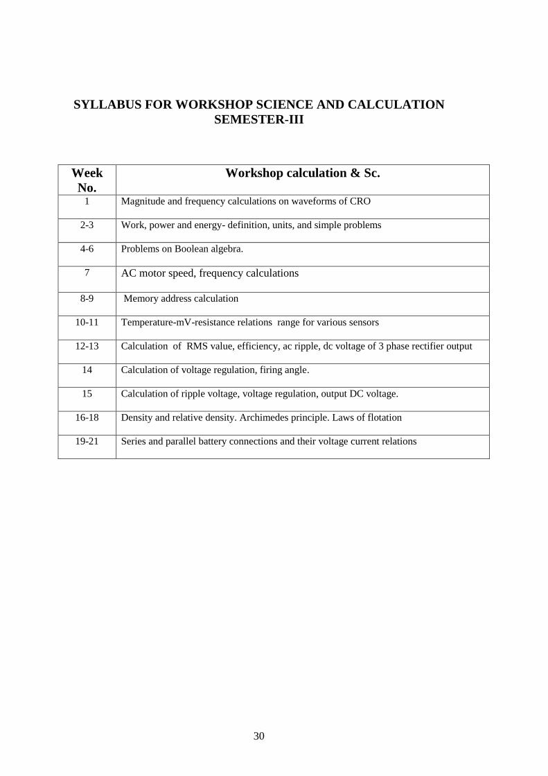
SYLLABUS FOR WORKSHOP SCIENCE AND CALCULATION
SEMESTER-III
Week
No.
Workshop calculation & Sc.
1
Magnitude and frequency calculations on waveforms of CRO
2-3 Work, power and energy- definition, units, and simple problems
4-6 Problems on Boolean algebra.
7 AC motor speed, frequency calculations
8-9 Memory address calculation
10-11 Temperature-mV-resistance relations range for various sensors
12-13 Calculation of RMS value, efficiency, ac ripple, dc voltage of 3 phase rectifier output
14 Calculation of voltage regulation, firing angle.
15 Calculation of ripple voltage, voltage regulation, output DC voltage.
16-18 Density and relative density. Archimedes principle. Laws of flotation
19-21 Series and parallel battery connections and their voltage current relations
31
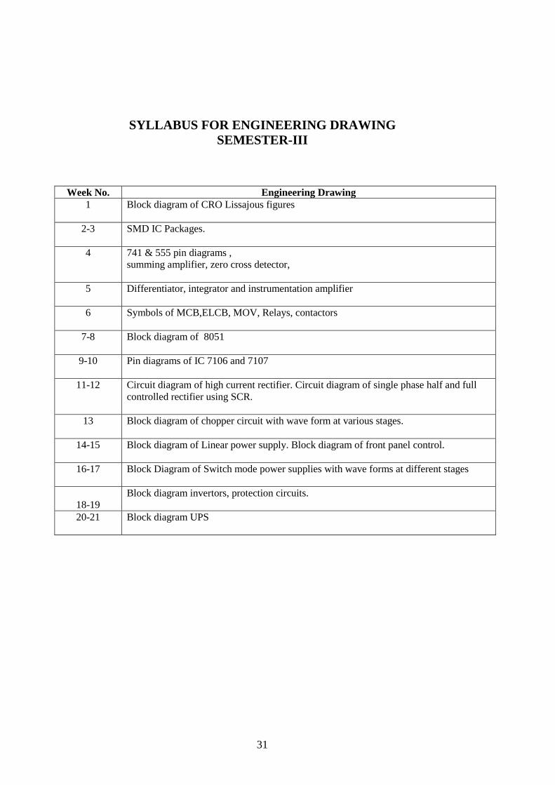
SYLLABUS FOR ENGINEERING DRAWING
SEMESTER-III
Week No. Engineering Drawing
1
Block diagram of CRO Lissajous figures
2-3 SMD IC Packages.
4 741 & 555 pin diagrams ,
summing amplifier, zero cross detector,
5 Differentiator, integrator and instrumentation amplifier
6 Symbols of MCB,ELCB, MOV, Relays, contactors
7-8 Block diagram of 8051
9-10 Pin diagrams of IC 7106 and 7107
11-12 Circuit diagram of high current rectifier. Circuit diagram of single phase half and full
controlled rectifier using SCR.
13 Block diagram of chopper circuit with wave form at various stages.
14-15 Block diagram of Linear power supply. Block diagram of front panel control.
16-17 Block Diagram of Switch mode power supplies with wave forms at different stages
18-19
Block diagram invertors, protection circuits.
20-21 Block diagram UPS
32
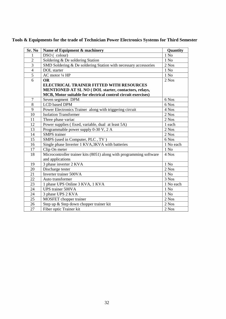
Tools & Equipments for the trade of Technician Power Electronics Systems for Third Semester
Sr. No Name of Equipment & machinery Quantity
1 DSO ( colour) 1 No
2 Soldering & De soldering Station 1 No
3 SMD Soldering & De soldering Station with necessary accessories 2 Nos
4 DOL starter 1 No
5 AC motor ¼ HP 1 No
6 OR
ELECTRICAL TRAINER FITTED WITH RESOURCES
MENTIONED AT SL NO ( DOL starter, contactors, relays,
MCB, Motor suitable for electrical control circuit exercises)
2 Nos
7 Seven segment DPM 6 Nos
8 LCD based DPM 6 Nos
9 Power Electronics Trainer along with triggering circuit 4 Nos
10 Isolation Transformer 2 Nos
11 Three phase variac 2 Nos
12 Power supplies ( fixed, variable, dual at least 5A) 1 each
13 Programmable power supply 0-30 V, 2 A 2 Nos
14 SMPS trainer 2 Nos
15 SMPS (used in Computer, PLC , TV ) 6 Nos
16 Single phase Inverter 1 KVA,3KVA with batteries 1 No each
17 Clip On meter 1 No
18 Microcontroller trainer kits (8051) along with programming software
and applications
4 Nos
19 3 phase inverter 2 KVA 1 No
20 Discharge tester 2 Nos
21 Inverter trainer 500VA 1 No
22 Auto transformer 3 Nos
23 1 phase UPS Online 3 KVA, 1 KVA 1 No each
24 UPS trainer 500VA 1 No
24 3 phase UPS 2 KVA 1 No
25 MOSFET chopper trainer 2 Nos
26 Step up & Step down chopper trainer kit 2 Nos
27 Fiber optic Trainer kit 2 Nos
33
Syllabus for the Trade of “Technician Power Electronics Systems”
Duration: 6 Months
Fourth Semester
Semester Code: PES: SEM IV
Industrial application of power Electronics
OBJECTIVES
Familiarize with various mechanical elements of machines
Troubleshoot solar, Inverters.
Wire field devices with PLC Modules and interpret the indications on PLC
Troubleshoot the failure using Diagnostic menu of PLC software
Familiarize with the AC Drive setup
Configure AC Drives
Control and monitor various motor parameters using VFD
Familiarize with the Servo Drive setup
Configure servo Drives
Control and monitor various motor parameters using servo Drive
Familiarize with DC Drive setup
Control and monitor various motor parameters using DC drive
34
SYLLABUS FOR TRADE PRACTICAL AND TRADE THEORY
SEMESTER-IV
Week
No Trade practical Trade theory
1 Solar Inverter
Connect and test solar panel to the
Inverter and run the load.
Mount a solar panel to a roof.
Wire a solar panel to a solar
controller.
Wire a solar controller to a battery
storage station.
Connect storage batteries to a power
inverter
Wire a power inverter to an electrical
service panel.
Test circuits for voltages.
Installation of Solar Inverter.
Take the trainees to the nearest solar
power installation and demonstrate
various aspects to cover skills as
specified above
Need for renewable energy sources, Solar energy
as a renewable resource. Materials used for solar
cells. Principles of conversion of solar light into
electricity. Basics of photovoltaic’s cell. Types
of solar cells. Mono crystalline and poly
crystalline PV cells.
Define Components like Solar cell, Module,
panel and Arrays. Factors that influence the
output of a PV module. SPV systems and the key
benefits. Difference between SPV and
conventional power. Define solar charge
controller or regulator and its role.
Safety precautions while working with solar
systems.
2-3 Sensor
Identify & test different sensors such as
RTDs, thermocouples, proximity
sensors( inductive, capacitive&
photoelectric) , load cells, strain gauge
& LVDT, Hall sensor, Tacho-generator
Test the functionality of all the sensors
mentioned above using the trainer kit
Refer the data chart & record various
parameter ranges in respect of the
sensors mentioned above
Digital control of field devices
Input Devices to develop START (Logic
1) and STOP (Logic 0) pulses
Develop AC – DC SIGNAL
CONVERTER using push to ON
switch, center tapped transformer
type full wave rectifier, filter and pot
to get Logic 1 (+ 5V); (START pulse
) view pulse on oscilloscope
Develop AC – DC SIGNAL
CONVERTER using push to ON
Basics of passive and active transducers
– Role, selection and characteristics.
Working principles of RTD, Thermocouple,
LVDT, Strain gauge, Proximity sensor, Hall
Sensor, Tacho-generator, optical sensors. Sensor
voltage and current formats
DIGITAL/LOGICAL/ON-OFF CONTROL
OF ELECTRICAL MACHINES AND
OTHER ACTUATORS Industrial control system: electro-magnetic
control, static control; comparison; general block
diagram; Information gathering section in input
section, Decision making section or logic section
and Actuating device section or output section;
advantages and disadvantages of static control
over magnetic relay control; input devices for
solid state logic; contact bounce problem;
35
switch, bridge type full wave rectifier
working on 24 V AC, filter, pot, 12V
DC reed relay and separate stabilized
+ 5V supply to get Logic 1; (START
pulse ) view pulse on oscilloscope
Develop AC – DC SIGNAL
CONVERTER using push to OFF
switch, center tapped transformer
type full wave rectifier, filter and pot
to get Logic 0 (0V); (STOP pulse )
view pulse on oscilloscope
Develop AC – DC SIGNAL
CONVERTER using push to OFF
switch, bridge type full wave rectifier
working on 24 V AC, filter, pot, 12V
DC reed relay and separate stabilized
+ 5V supply to get Logic 0 (0V);
(STOP pulse ) view pulse on
oscilloscope
Develop AC – DC SIGNAL
CONVERTER – using Opto –
coupler method, push to ON switch,
bridge type full wave rectifier
working on 24 V AC, filter, pot, opto
coupler or LDR & Lamp source and
separate stabilized + 5V supply to
develop START pulse
Capacitive Switch Filters
4-6 Electrical control of AC/DC machines
Identify of (unmarked) terminals of 3
phase induction motors
Construct a self hold contactor circuit
and run a 3-Phase Induction Motor
Familiarize with different types of
motor and identify different parts.
Study & connect the motor and run
(below 5hp) in star, note phase
Voltage, line voltage and current.
Study and connect and run the motor
in Delta and note phase current line
current. Phase voltage and line
voltage.
Connect and operate an induction
motor using DOL starter
Connect and run a 3-phase motor
using manual and automatic star-
delta starters.
Fundamentals of AC 3 phase & single phase
Induction motors, synchronous speed, slip, rotor
frequency , torque – speed characteristics,
Starters used for Induction motors, speed control
of Induction motors
Types of motors: Advantages & Disadvantages
among each others.
DC Motors– types, working, torque speed
characteristics, staring of DC Motors & change
the DOR, 3 point and 4 point Starters, speed
control of DC motor, Field flux control &
armature current control.
Brushless DC Motors.
36
Change the direction of rotation of
Induction motor
Connect & run three phase induction
motors in a sequence using contactor
& relay
Construct run, stop and jog in both
directions of an induction motor
Understand all the information on a
Motor template.
Familiarize with diff. types of DC
motors.
Connect & run DC shunt motor using
3 point starter.
Change the direction of rotation of
DC motor
Control the speed of DC motor by
armature control method
Control the speed of DC motor by
field control method
7
Mechanical machine elements
Visit to any industry to have exposure on
mechanical elements of different machines
like Lathe, planning, milling machines and
their control cabinets..
Basics of mechanical machine transmission
mechanism such as gears, clutches , couplings,
barring, belts, carriage beds, coolant & lubricant
mechanism, linear scales
8 DC Machine control
Construct circuit for speed control of
DC shunt motor. (phase control
method)
Construct PWM circuit for the speed
control of DC shunt motors.
Control the speed of DC shunt motor
using SCR chopper by using
trainer.
DC drives-their principle and working,
Types of DC drives- Phase control, PWM,
Chopper.
Open loop speed control system,
Close Loop speed control system.
9-11 AC Drives
Study the AC Drive set up and its
connections
Identify different cables and
connectors used in the AC DRIVE
setup
Identify various input and output
terminals of the DRIVE unit,
Operator panel and display unit.
Familiarization with PMU &
different terminals of Micro – Master
AC Drive
Block diagram of AC Drive – (Sources of supply
– Converter /Rectifier – DC Link – Inverter –
Motor Load) 1 phase & 3 phase rectifier circuits.
Inverter – 1 phase Inverter 3 phase Inverter
Switching circuit (Sequence and Switching
timing control – PWM Technique &
Switching Devices.
Microprocessor / Microcontroller) –
VFD (Variable Frequency Drive)
VV VF Control – (3 phase induction
motor) Speed control.
37
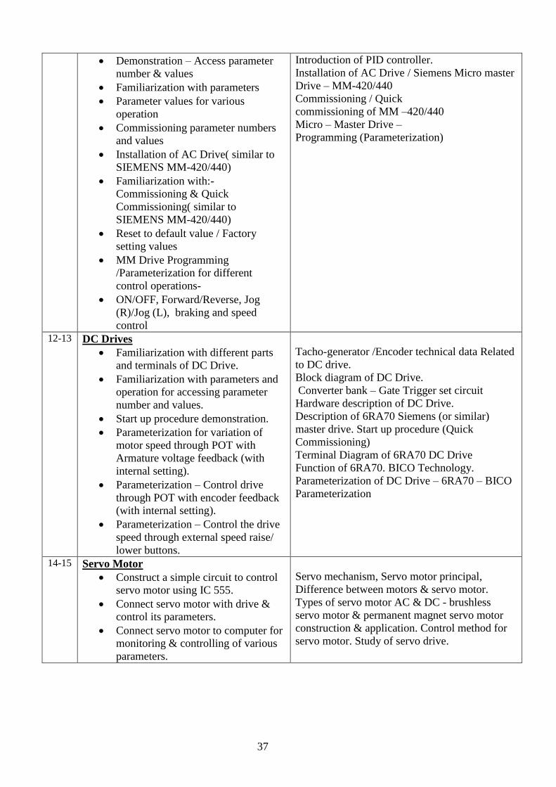
Demonstration – Access parameter
number & values
Familiarization with parameters
Parameter values for various
operation
Commissioning parameter numbers
and values
Installation of AC Drive( similar to
SIEMENS MM-420/440)
Familiarization with:-
Commissioning & Quick
Commissioning( similar to
SIEMENS MM-420/440)
Reset to default value / Factory
setting values
MM Drive Programming
/Parameterization for different
control operations-
ON/OFF, Forward/Reverse, Jog
(R)/Jog (L), braking and speed
control
Introduction of PID controller.
Installation of AC Drive / Siemens Micro master
Drive – MM-420/440
Commissioning / Quick
commissioning of MM –420/440
Micro – Master Drive –
Programming (Parameterization)
12-13 DC Drives
Familiarization with different parts
and terminals of DC Drive.
Familiarization with parameters and
operation for accessing parameter
number and values.
Start up procedure demonstration.
Parameterization for variation of
motor speed through POT with
Armature voltage feedback (with
internal setting).
Parameterization – Control drive
through POT with encoder feedback
(with internal setting).
Parameterization – Control the drive
speed through external speed raise/
lower buttons.
Tacho-generator /Encoder technical data Related
to DC drive.
Block diagram of DC Drive.
Converter bank – Gate Trigger set circuit
Hardware description of DC Drive.
Description of 6RA70 Siemens (or similar)
master drive. Start up procedure (Quick
Commissioning)
Terminal Diagram of 6RA70 DC Drive
Function of 6RA70. BICO Technology.
Parameterization of DC Drive – 6RA70 – BICO
Parameterization
14-15 Servo Motor
Construct a simple circuit to control
servo motor using IC 555.
Connect servo motor with drive &
control its parameters.
Connect servo motor to computer for
monitoring & controlling of various
parameters.
Servo mechanism, Servo motor principal,
Difference between motors & servo motor.
Types of servo motor AC & DC - brushless
servo motor & permanent magnet servo motor
construction & application. Control method for
servo motor. Study of servo drive.
38
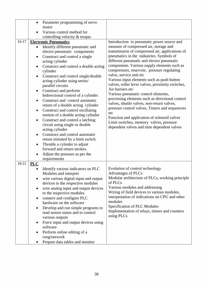
Parameter programming of servo
motor
Various control method for
controlling velocity & torque. 16-17 Electronic Pneumatics
Identify different pneumatic and
electro pneumatic components
Construct and control a single
acting cylinder
Construct and control a double acting
cylinder
Construct and control single/double
acting cylinder using series/
parallel circuits
Construct and perform
bidirectional control of a cylinder.
Construct and control automatic
return of a double acting cylinder
Construct and control oscillating
motion of a double acting cylinder
Construct and control a latching
circuit using single or double
acting cylinder
Construct and control automatic
return initiated by a limit switch.
Throttle a cylinder to adjust
forward and return strokes.
Adjust the pressure as per the
requirements
Introduction to pneumatic power source and
measure of compressed air, storage and
transmission of compressed air, applications of
pneumatics in the industries. Symbols of
different pneumatic and electro pneumatic
components. Various supply elements such as
compressors, reservoir, pressure regulating
valve, service unit etc
Various input elements such as push button
valves, roller lever valves, proximity switches,
Air barriers etc
Various pneumatic control elements,
processing elements such as directional control
valves, shuttle valves, non-return valves,
pressure control valves, Timers and sequencers
etc
Function and application of solenoid valves
Limit switches, memory valves, pressure
dependent valves and time dependent valves
18-21 PLC
Identify various indicators on PLC
Modules and interpret
wire various digital input and output
devices to the respective modules
wire analog input and output devices
to the respective modules
connect and configure PLC
hardware on the software
Develop and run simple programs to
read sensor status and to control
various outputs
Force input and output devices using
software
Perform online editing of a
rung/network
Prepare data tables and monitor
Evolution of control technology
Advantages of PLCs
Modular architecture of PLCs, working principle
of PLCs
Various modules and addressing
Wiring of field devices to various modules,
interpretation of indications on CPU and other
modules
Specification of PLC Modules
Implementation of relays, timers and counters
using PLCs
39
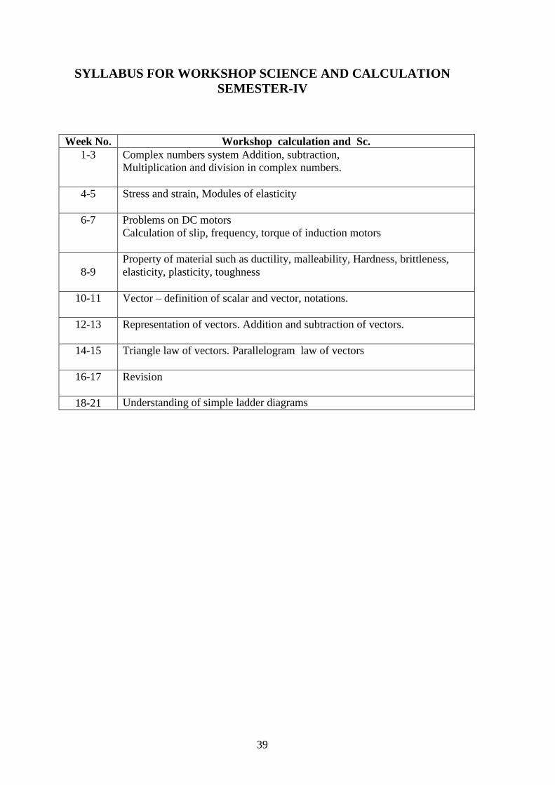
SYLLABUS FOR WORKSHOP SCIENCE AND CALCULATION
SEMESTER-IV
Week No. Workshop calculation and Sc.
1-3 Complex numbers system Addition, subtraction,
Multiplication and division in complex numbers.
4-5 Stress and strain, Modules of elasticity
6-7 Problems on DC motors
Calculation of slip, frequency, torque of induction motors
8-9
Property of material such as ductility, malleability, Hardness, brittleness,
elasticity, plasticity, toughness
10-11 Vector – definition of scalar and vector, notations.
12-13 Representation of vectors. Addition and subtraction of vectors.
14-15 Triangle law of vectors. Parallelogram law of vectors
16-17 Revision
18-21 Understanding of simple ladder diagrams
40
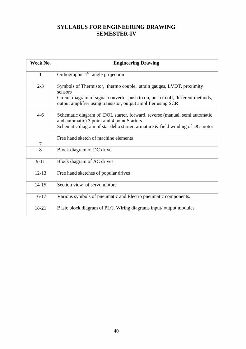
SYLLABUS FOR ENGINEERING DRAWING
SEMESTER-IV
Week No. Engineering Drawing
1 Orthographic 1st angle projection
2-3 Symbols of Thermistor, thermo couple, strain gauges, LVDT, proximity
sensors
Circuit diagram of signal convertor push to on, push to off, different methods,
output amplifier using transistor, output amplifier using SCR
4-6 Schematic diagram of DOL starter, forward, reverse (manual, semi automatic
and automatic) 3 point and 4 point Starters
Schematic diagram of star delta starter, armature & field winding of DC motor
7
Free hand sketch of machine elements
8 Block diagram of DC drive
9-11 Block diagram of AC drives
12-13 Free hand sketches of popular drives
14-15 Section view of servo motors
16-17 Various symbols of pneumatic and Electro pneumatic components.
18-21 Basic block diagram of PLC. Wiring diagrams input/ output modules.
41
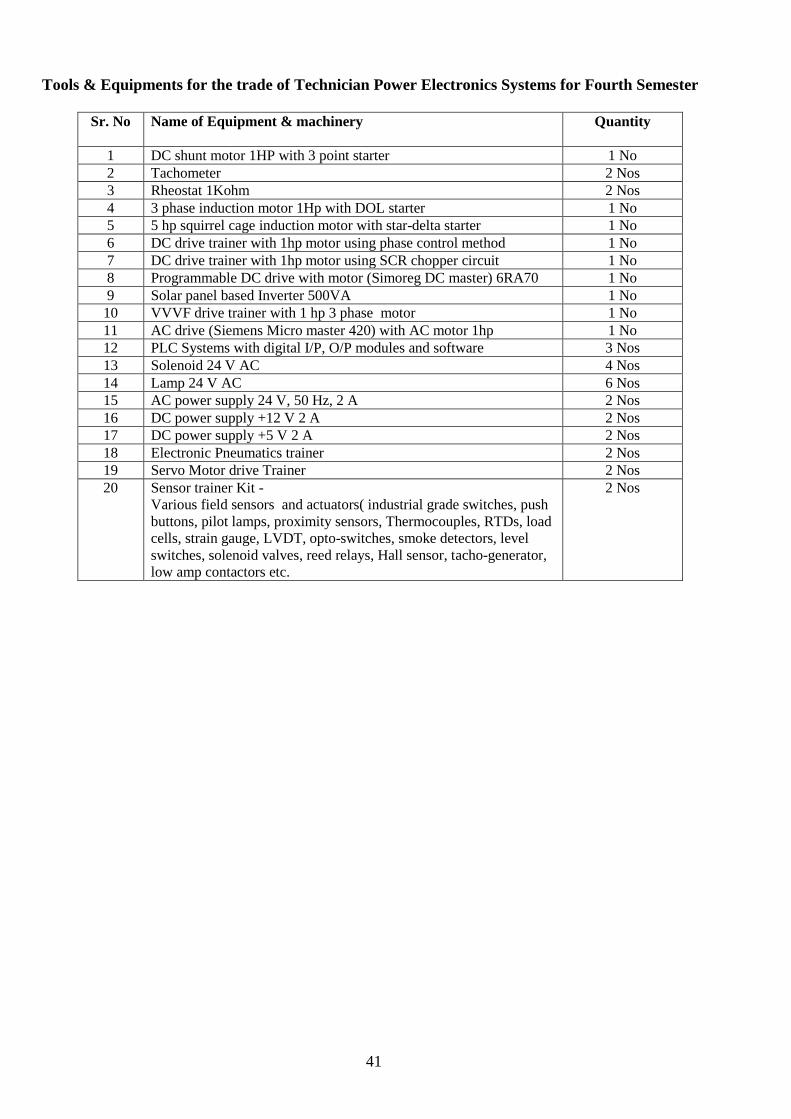
Tools & Equipments for the trade of Technician Power Electronics Systems for Fourth Semester
Sr. No Name of Equipment & machinery Quantity
1 DC shunt motor 1HP with 3 point starter 1 No
2 Tachometer 2 Nos
3 Rheostat 1Kohm 2 Nos
4 3 phase induction motor 1Hp with DOL starter 1 No
5 5 hp squirrel cage induction motor with star-delta starter 1 No
6 DC drive trainer with 1hp motor using phase control method 1 No
7 DC drive trainer with 1hp motor using SCR chopper circuit 1 No
8 Programmable DC drive with motor (Simoreg DC master) 6RA70 1 No
9 Solar panel based Inverter 500VA 1 No
10 VVVF drive trainer with 1 hp 3 phase motor 1 No
11 AC drive (Siemens Micro master 420) with AC motor 1hp 1 No
12 PLC Systems with digital I/P, O/P modules and software 3 Nos
13 Solenoid 24 V AC 4 Nos
14 Lamp 24 V AC 6 Nos
15 AC power supply 24 V, 50 Hz, 2 A 2 Nos
16 DC power supply +12 V 2 A 2 Nos
17 DC power supply +5 V 2 A 2 Nos
18 Electronic Pneumatics trainer 2 Nos
19 Servo Motor drive Trainer 2 Nos
20 Sensor trainer Kit -
Various field sensors and actuators( industrial grade switches, push
buttons, pilot lamps, proximity sensors, Thermocouples, RTDs, load
cells, strain gauge, LVDT, opto-switches, smoke detectors, level
switches, solenoid valves, reed relays, Hall sensor, tacho-generator,
low amp contactors etc.
2 Nos
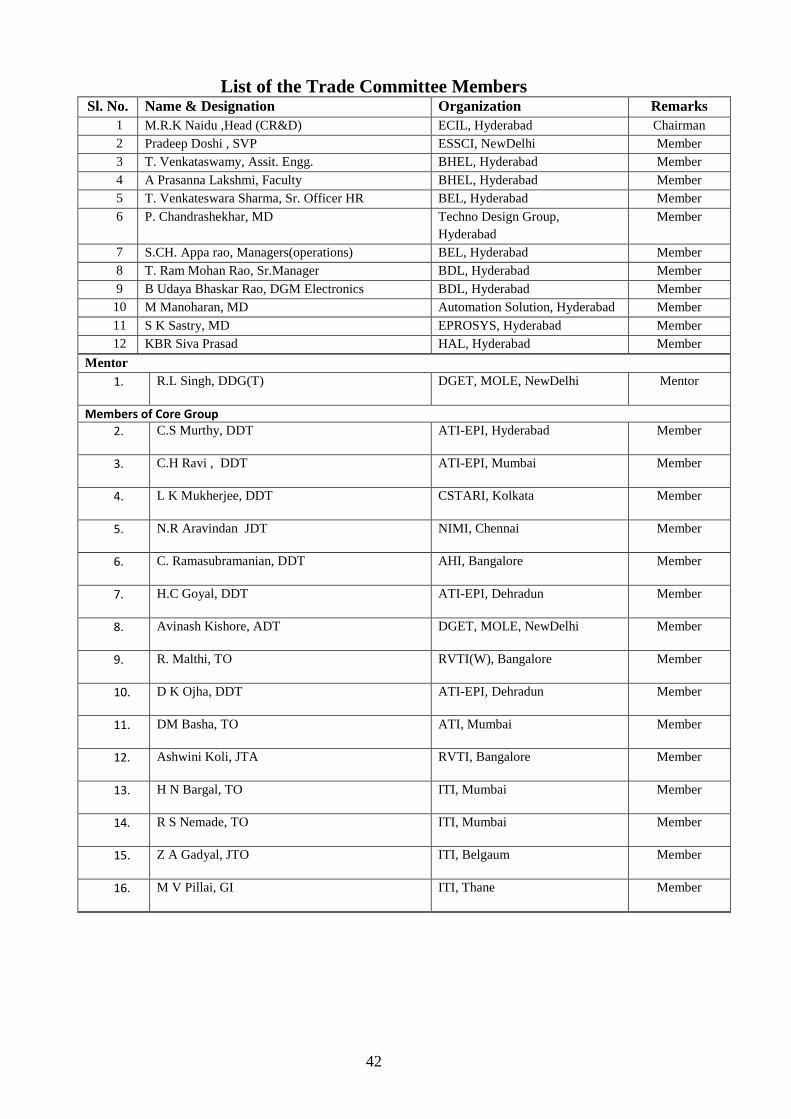
42
List of the Trade Committee Members
Sl. No. Name & Designation Organization Remarks
1 M.R.K Naidu ,Head (CR&D) ECIL, Hyderabad Chairman
2 Pradeep Doshi , SVP ESSCI, NewDelhi Member
3 T. Venkataswamy, Assit. Engg. BHEL, Hyderabad Member
4 A Prasanna Lakshmi, Faculty BHEL, Hyderabad Member
5 T. Venkateswara Sharma, Sr. Officer HR BEL, Hyderabad Member
6 P. Chandrashekhar, MD Techno Design Group,
Hyderabad
Member
7 S.CH. Appa rao, Managers(operations) BEL, Hyderabad Member
8 T. Ram Mohan Rao, Sr.Manager BDL, Hyderabad Member
9 B Udaya Bhaskar Rao, DGM Electronics BDL, Hyderabad Member
10 M Manoharan, MD Automation Solution, Hyderabad Member
11 S K Sastry, MD EPROSYS, Hyderabad Member
12 KBR Siva Prasad HAL, Hyderabad Member
Mentor
1. R.L Singh, DDG(T) DGET, MOLE, NewDelhi Mentor
Members of Core Group
2. C.S Murthy, DDT ATI-EPI, Hyderabad Member
3. C.H Ravi , DDT ATI-EPI, Mumbai Member
4. L K Mukherjee, DDT CSTARI, Kolkata Member
5. N.R Aravindan JDT NIMI, Chennai Member
6. C. Ramasubramanian, DDT AHI, Bangalore Member
7. H.C Goyal, DDT ATI-EPI, Dehradun Member
8. Avinash Kishore, ADT DGET, MOLE, NewDelhi Member
9. R. Malthi, TO RVTI(W), Bangalore Member
10. D K Ojha, DDT ATI-EPI, Dehradun Member
11. DM Basha, TO ATI, Mumbai Member
12. Ashwini Koli, JTA RVTI, Bangalore Member
13. H N Bargal, TO ITI, Mumbai Member
14. R S Nemade, TO ITI, Mumbai Member
15. Z A Gadyal, JTO ITI, Belgaum Member
16. M V Pillai, GI ITI, Thane Member