Embed Size (px)
Citation preview

– 1 –
I5: A Model-Based Framework for Architecting
System-of-Systems Interoperability,
Interconnectivity, Interfacing, Integration, and
Interaction
Yaniv Mordecai1 and Dov Dori1,2
1. Technion, Israel Institute of Technology
2. Massachusetts Institute of Technology
[email protected], [email protected]
Copyright © 2013 by Author Name. Published and used by INCOSE with permission.
Abstract. We present I5
— Interoperability, Interconnectivity, Interfacing, Integration, and
Interaction — a Model-Based Framework for Architecting Systems-of-Systems.
Interoperability programs deliver end-to-end cooperation and collaboration capabilities and
services among organizations, users, systems, and infrastructures, on top of a set of existing
systems. Each system has its own programmatic and technical constraints and issues.
System-level stakeholders usually prefer core functionality over integration, and expect the
interconnectivity infrastructure to be transparent and simple, regardless of its actual cost,
complexity, or criticality. Hence, coordinating and aligning the multiple system and team
efforts in order to reach a synergetic effect is a challenge that many integration professionals in
the cyber, energy, manufacturing, and traffic domains are familiar with. Traditional
system-centered design methods fail to capture interconnectivity and collaboration aspects and
issues, and they are of little interest to the individual systems’ stakeholders. The framework we
propose is based on Object–Process Methodology, an emerging ISO standard (ISO 19450) for
modeling and design of complex, dynamic, and multidisciplinary systems. Our framework
facilitates a smooth transition from a set of disparate system-centered views to a consolidated,
integrated model, which accounts for integration aspects, interface and payload structure and
behavior, interconnectivity processes and services, and eventually emergent interoperability
capabilities.
Keywords: Systems of Systems, Enterprise Integration, Interoperability, Interconnectivity,
Interface Modeling, Model Based Systems Engineering, Object Process Methodology.
1. Introduction
Interconnectivity and interoperability are two emergent, synergetic qualities of systems of
systems or circumstantial, ad-hoc corporations of systems. Interconnectivity is the ability of a
group of systems to connect, exchange information or other payloads, and maintain a reliable
connection for the benefit of their users. Interoperability is the ability of organizations and
users to utilize the interconnectivity co-exhibited by the systems that serve them, in order to

– 2 –
cooperate and collaborate, carry out business or operational transactions, and share and
exchange goods and information. The integration of disparate, independent systems facilitates
end-to-end interconnectivity among systems and infrastructures and, on top of it,
interoperability among enterprises and users. It supports regulation and compliance control,
additional capabilities to users, manual coordination avoidance, shorter transaction time,
complex, and challenging operational processes.
Integrating disparate independent systems up to an interoperable formation of systems and
organizations is different and more challenging than the integration of several products or
subsystems to a functioning system. While the latter is distinctively the system engineer’s
responsibility, the former is often left unaddressed. Each system engineer takes care of his or
her own system’s functionality. Still, someone must orchestrate the entire program, define and
control the integration requirements and specifications, and engineer the media and auxiliary
components and services through which interaction is enabled. This is the basis for
systems-of-systems (SoS) engineering theory and practice (Sage and Lynch 1998).
SoS integration can be a complex, risky, long, and frustrating effort, as integration has an
impact on the individual system and its users, who must adapt to collaboration with other
systems. The impact can be as minor as an additional interface, client, or capacity, but it can
also require significant modifications, such as architecture redesign, replacement of whole
modules, multiple setups, and adjustments to business processes, decision-making, and
policy-making. Major impacts may lead to cancellation, postponement, or avoidance of the
integration. When integration is unavoidable, and the systems to be integrated still fail to adapt
to each other at high levels, the entire integration effort can fail to provide the anticipated
benefits at the business or operational levels, even though it may work perfectly on the
technical level. Therefore, integration is a significant and central risk in every complex system
and system of systems, and must be handled appropriately. Nevertheless, Traditional
system-centered design methods often fail to provide an adequate integration-centered
perspective that captures the intricate connectivity and collaboration aspects and issues.
Systems are primarily designed and developed to provide core functionalities for their own
users, and utilize interoperability and interconnectivity to enhance these core functionalities.
Integration functionalities compete for resources and attention with core functionalities, but the
latter are often more critical to system users than the integration with other systems.
Interoperability programs are unique cases of system development and deployment, whose
primary goal is to enable new end-to-end synergetic functionalities. These programs use
available core functionalities of the individual systems, with as little modification or
adjustment as possible. System-level stakeholders are gradually acknowledging the benefits of
interconnectivity, but usually still prefer to invest in core functionalities, preserve their assets,
and avoid the costs and organizational impacts incurred by the need for cooperation and
collaboration. Despite this, they are often compelled to undergo integration due to regulation,
executive decisions, or mergers and acquisitions. A consortium of stakeholders or a larger,
senior stakeholder (such as a government) is sometimes required to assume responsibility for

– 3 –
the interconnectivity infrastructure, and it often appoints personnel responsible for
infrastructure development and operation.
Paradoxically, such interconnectivity infrastructure is expected to be “transparent” to end
users. As far as end-users are concerned, a simple cable or pipe is the interface that enables the
interaction with the other system. This is also how it is typically illustrated when modeling the
integration from the individual system’s perspective. The infrastructure is expected to function
flawlessly, regardless of its actual complexity, cost or criticality. It becomes a criticized issue
only when it ceases to provide interconnectivity according to an expected level of service. The
infrastructure is often expected to defend its clients against various risks, e.g., overloading,
attacks, and misuse, compensate for users' incompetence, and even act on their behalf
(Mordecai, Focsenianu, and Elzon 2011). Eventually, unjust as this may sound, it can be
blamed for its clients’ inability to utilize it appropriately.
This paper proposes a framework for the engineering of systems-of-systems integration
programs. Our model-based systems engineering framework draws on the theory and
methodology of systems-of-systems integration and interoperability and captures the
integration domain as a system per se. This framework equips integration program managers
and interoperability designers with the means to model, design, analyze, control, maintain, and
utilize the interconnectivity infrastructure. It provides individual system engineers with a
perspective on the integration domain, allowing them to refer to the infrastructure as being
transparently without ignoring its complexity whenever the need to address this complexity
arises.
The main advantage of our framework is the smooth transition it facilitates from a set of
disparate system-centered views towards a consolidated, integrative model. It provides holistic
understanding of integration aspects, interface structure, interconnectivity processes and
services, and eventually emergent interoperability capabilities. Moreover, the framework
increases the individual system engineer’s awareness of the environment in which the system
operates. It highlights the intricate connections of the system with the environment and with
other systems in the environment, and the complexity of cross-system interactions. This
awareness helps design better, more resilient and more robust systems, considering interaction
aspects as an integral part of the system design process.
Our underlying framework is OPM – Object–Process Methodology (Dori 2002) – a
structured conceptual framework for modeling and design of multidisciplinary, complex, and
dynamic systems and systems-of-systems. OPM has a formal syntax and a bimodal textual and
visual representation, which makes it appealing to both sides of the brain. OPM is an emerging
ISO standard (ISO 19450), and an underlying framework for process and system modeling
within ISO standards. OPM’s simple yet robust notation enables the addition of modeling
layers on top of, and in sync with the core system model, thus providing for coordinated and
consistent multi-layered modeling. OPM’s unique approach for handling system complexity
enables complex interface and interconnectivity infrastructure modeling and design at various
levels of detail.

– 4 –
The rest of this paper is organized as follows: Section 2 provides a literature review,
focusing on Systems-of-Systems theory, Interoperability theory, and Object Process
Methodology. Section 3 illustrates our modeling framework for integration programs, based on
OPM, its advantages, and the reasons for electing to use this methodology for our purpose.
Section 4 describes a simple example concerning medical systems interoperability. Finally,
Section 5 discusses benefits, limitations, future extensions, and implementation of our
model-based system-of-systems interoperability framework.
2. Literature Review
Interconnectivity and Interoperability
Complex systems integration is a dominant research and practice subject in defence (Sage
and Lynch 1998; Brooks and Sage 2006), information technology (Sheth 1998; Boehm 2006),
and manufacturing and supply chains (Parks et al. 1994; Williams et al. 1994; Nof et al. 2006;
Panetto, Jardim-Goncalves, and Molina 2012). Holistic approaches to enterprise integration
and general systems-of-systems integration have also emerged as the need to integrate systems
from various domains has increased (Vernadat 2007; Chen, Doumeingts, and Vernadat 2008;
Naudet et al. 2010).
The LISI (Levels of Information Systems Interoperability) framework (C4ISR Architecture
Working Group 1998) defines a reference scale for assessing interoperability between systems,
with five maturity levels: e) isolated/manual, d) connected/peer-to-peer, c) functional/
distributed, b) domain/integrated, and a) enterprise/universal. LISI identifies four attributes of
the interoperability scope for which different maturity levels may apply: procedures,
applications, infrastructure, and data.
Two prominent architecture frameworks are NATO Architecture Framework (NAF), and
The Open Group Architecture Framework (TOGAF). NAF focuses on complex military
systems interoperability, while TOGAF focuses on commercial and industrial information
systems interoperability (Jørgensen, Liland, and Skogvold 2011). The coordination and
alignment of these two frameworks through a model-based integrated approach is also
discussed, using the Unified Modelling Language (UML).
Interoperability has recently become a scientific branch of its own, and various ontologies
and formal theories have been proposed to underpin it, as reviewed by (Lamparthaki et al.
2012). Interoperability and interconnectivity research appears to be focused on information
technology, lacking sufficient coverage of other domains. To the best of our knowledge, there
is no structured, practical model-based approach to the design of interfaces and interactions
among disparate systems. As a benchmark, we expected to find such an approach in UML or
SysML metamodels, but we could not identify a significant resource that provided a
framework for this problem (Estefan 2007; Sharon and Dori 2009).

– 5 –
Object Process Methodology
Object–Process Methodology, or OPM (Dori 2002), is a holistic, integrated approach to the
design and development of systems in general and complex dynamic systems in particular.
Using a minimal set of symbols, OPM integrates the functional, structural, and procedural
views of a system in one view, expressed both graphically and textually. There is only one
diagram type in OPM, as opposed to UML’s 13 or SysML’s 9 diagram types. OPM copes with
complexity via detail-level decomposition, in contrast to UML and SysML aspect
decomposition (into structure, behaviour, state transitions, activities, time flow, etc.).
OPM building blocks are objects and processes, collectively called things. Objects are
things that exist and can be stateful (that is, have states). Processes are things that occur and
transform objects: they generate and consume objects, or affect stateful objects by changing
their state. These building blocks are connected by two types of links: structural and
procedural. Structural links specify relations between objects, or between processes.
Conversely, procedural links connect processes with objects or object states. OPM supports the
designation of things by their affiliation attribute as systemic or environmental, and by their
essence attribute as physical or informatical. A brief description of OPM notation,
accompanied by illustrations and comments, is provided in Appendix A.
An OPM model consists of a set of hierarchically organized Object-Process Diagrams
(OPDs). The hierarchical structure alleviates system complexity through three mechanisms:
(1) Unfolding and folding of structural hierarchies of things (primarily objects); (2) Zooming
into or out of the inner details of things (primarily processes), and (3) Expressing or
suppressing the states of objects. Each OPD is obtained by in-zooming or unfolding an object
or a process in its ancestor OPD. The graphical representation of an object is a rectangle, while
an ellipse represents a process. Object states are represented by round-angle rectangles
(“rountangles”) within their owning object. The OPD hierarchical structure is accompanied by
a corresponding set of structured textual model description sentences, which are written in
Object-Process Language (OPL), a subset of English. With OPCAT (OPM’s free CASE tool),
OPL sentences are automatically generated in response to visual edits of the model. The textual
formulation is equivalent to the graphical view, allowing for bimodal textual and visual
description that enhances understanding of the model.
OPM was selected as the basis for this framework due to its following features:
1. Unification of the static-structural and dynamic-procedural aspects, using a single
diagram type, at varying levels of detail, which reduces clutter and incompatibilities,
even in highly complex systems;
2. Inherent complexity management by decomposing system specification into
self-similar OPDs at increasing levels of detail, achieved through recursive seamless
refinement–abstraction mechanisms;
– 6 –
3. A combination of semantically equivalent graphical and textual views, which makes
OPM appealing to both sides of the human brain, catering to systems architects, domain
experts, professionals and practitioners;
4. Inherent capability to extend the core system model to additional aspects while
maintaining full coordination with the core model
5. The capability to generate meta-models, which are generic, multi-purpose models and
patterns that can be instantiated and adapted for specific systems and problems;
6. A freely available CASE tool, OPCAT1, which implements almost all OPM concepts
and allows rapid adaptation and implementation, and
7. The fact that OPM is currently in the process of becoming an ISO PAS (Publically
Available Specification), ISO 19450, and a basis for system and process modeling in
ISO enterprise standards. This standardization enables accelerated dissemination of
OPM as a basis for enterprise modeling in general and integration modeling in
particular.
8. OPM’s and OPCAT’s proven capability to capture complex interactions, including
complexity management and alleviation, and built-in simulation (Dori,
Reinhartz-berger, and Sturm 2003).
3. I5 : Interoperability, Interconnectivity, Interfacing, Integration,
and Interaction
This section introduces I5
– a framework for modeling, designing, evaluating, and
controlling integration programs. The order of the terms interoperability, interconnectivity,
interfacing, integration, and interaction, from which the framework derives its name,
reflects the evolution of interoperability, and the organizing principle of our framework.
Interoperability is the ultimate goal, but it is important to begin by understanding and capturing
its essence – in the form of organizations and users sharing something among them.
Interconnectivity is the capability of the systems serving these users to connect and enable
interoperability. Interfacing is the capability of the member systems and sub-systems to utilize
the interconnectivity among them by exposing the services and interfaces to handle the various
products of interest. Integration is the process of coordination and alignment of all interfaces to
work together, for the benefit of all member systems and for the synergetic effect expected at
the system-of-systems level. Finally, interaction is the set of realization and utilization of the
capabilities, in various modes and fashions, to cooperate, collaborate, and conduct end-to-end
transactions, which implement the idea of interoperability on a daily basis.
This framework is founded on the idea that the infrastructure that encompasses I5 is a system
in its own right. It has functions, boundaries, inputs and outputs, components and attributes.
1 Downloadable free from http://esml.iem.technion.ac.il/

– 7 –
Hence, the five aspects of I5 can be architected and modeled following the principles of
architecting and modeling of any system. However, there are unique challenges stemming from
the need to coordinate the disparate member systems, which, in essence, are not obliged to be
coordinated. Several components of the same system must be coordinated for the system to
function properly, and therefore there are less degrees of freedom, and more constraints, which
alleviate the complexity of integration and interaction.
Our I5
framework basically follows OPM notation, so it can be implemented and executed
with OPCAT. We propose several extensions to OPM formal notation. These extensions are
discussed next, as part of the meta-modeling of the concepts comprising and underpinning this
framework.
Infrastructure is the assembly of all the components, media, services, and functions,
facilitating at least some of the I5 functionalities. The infrastructure may or may not exist as a
physical, tangible entity, but it must be explicitly defined, especially in
interoperability-centered programs, integrating several disparate systems to form an
interoperable system-of-systems. Traditional system-centered design often perceives the
infrastructure as a simple link, and ignores all the intricate routes and processes allowing the
interconnectivity and interoperability of the two (or more) ends. It is indeed often useful to
conceal the entire interaction behind a single link. In the I5 framework, the infrastructure is a
compound OPM object: it comprises (lower level) objects and processes. OPM’s in-zooming
mechanism allows the designer to construct a hierarchy of system diagrams, in which more
details are provided in successively deeper levels. In-zooming usually serves for detail
refinement of objects and processes, but not for links. Referring to a link as an object, this
object's structure and operation are exposed by zooming into the link connecting two objects
that interact through the infrastructure.
Medium is the means within the infrastructure that carries payload (described in the next
paragraph). Common, man-made media include wires, cables, fibers, pipes, conveyor belts,
roads, and bridges. More immersive media are the air or atmosphere, time-space, and
cyberspace. The atmosphere is the medium through which radio and light waves propagate,
carrying information and energy; time-space is the medium through which payloads travel, and
cyberspace is an almost metaphorical medium within which information is transmitted. Force
and energy are means of interaction at the physical level. For example, the field of gravity is an
interface between two bodies, and the electromagnetic field is the interface between
sub-atomic particles. Auxiliary components handle the payload while en-route, and carry out
various important interconnectivity management tasks, including cyber and physical security
and safety assurance, content validation and filtering, standardization, regulation, and
compliance control, traffic monitoring and control, storage and buffering, service level
assurance, billing, abuse detection, conversion and transformation, amplification and
multiplication, distribution, and delivery guaranteeing.
Payload is any transferrable object, e.g., information, matter, material, energy, or currency.
In UML/SysML, while payload is clearly a class/block, it is often unclear whether it is a
component (e.g., control, or boundary) or an entity. UML’s stereotyping mechanism improves

– 8 –
model clarity in this respect, but it is not widely used. Furthermore, since UML is a software
modeling language, it cannot make the distinction between the actual physical entity and its
computerized representation, e.g., a person, and the person’s record, or a physical movement,
and the physical movement’s informatical representation or documentation. Legacy block
diagrams usually show payload in the text tag on top of the link that marks the interface through
which it is conveyed. However, these text tags often describe the services and actions
performed between the objects, or even the type of the medium underlying the interface, which
confuses design users and readers. In UML, the text tags on the links usually describe relations
– the ways one class affects another. OPM payloads are defined as independent objects. We use
OPM’s notation to distinguish ( ) from payload (not shaded). shading component shaded
Components exhibit processes that yield or consume payloads. Note that when the payload is
continuous, like water or light waves, it must be quantized – defined in some dimensions as a
singular unit of measure (such as cubic meters of water, or watts of light emission).
OPM advocates the use of procedural modeling to capture the dynamic aspects of the
system. This approach differs from the classical static block diagram approach, in which
activities and processes are concealed in their hosting components, represented as objects (or
classes/blocks). In UML, for instance, classes expose methods, which provide or consume data
to or from other classes. The dynamic aspect is captured in UML/SysML in the Use-Case
Diagram, Activity Diagram, Sequence Diagram (Favre 2003), and State-chart (Harel and Politi
1998). However, each diagram provides a different perspective on the dynamics of the system.
OPM requires a defined process to transform (create, consume, or change the state of) the
object, in order to capture the procedural aspect of the system. This notation captures the
form-function duality (Crawley et al. 2004).
The component-payload relation, which is essentially a compact notation, concealing a
procedural aspect, is obtained by OPM’s suppression mechanism. This mechanism is
commonly applied to object states, all or some of which may be suppressed when the exact
state enabling an object-process relation is not important at a higher, less-detailed model level.
After a process is explicitly defined, process suppression causes the object comprising the
process to assume the role of its process. “Coffee Machine yields Cup of Coffee” is an OPL
sentence implying that Coffee Machine, an object, exhibits a process, apparently called
“Coffee Making”, which yields the object Cup of Coffee. “Coffee Machine consumes Coffee,
Milk, Sugar, and Water” implies that the Coffee Making process in the Coffee Machine
consumes these raw materials. Likewise, a payload conveying process is exhibited by the
infrastructure, or one of its components or media.
Interface, with which a system interacts, is modeled as an OPM object exhibiting a payload
handling process. Process suppression can be applied to interfaces in order to obtain the port
style, as in SysML Block Definition Diagram or UML Component Diagram. A port is a
component’s interface, by which the component connects to other systems or components,
receives input, and/or provides output. When it becomes important to display the payload
handling process, it can be easily expressed, reassuming its role on behalf of its owning
component. Process suppression can also be applied to a dynamic payload, which has its own

– 9 –
processes or methods. This is useful for payloads that are capable of moving themselves, and
which can change while moving, like light or radio waves, or agents acting as independently
functioning objects.
The Integrated Meta-Model
We begin with a clear modeling of interoperability, as captured in Figure 1. This is a
compact view, showing only the interacting users, and the payloads they share, in the order of
occurrence. This compact view is useful for an initial description of processes among users of
disparate member systems. This description strongly appeals to operational stakeholders and
top users, since this is how they tend to describe the processes they participate in. The
following clause is an annotated example: “The buyer (a user) transfers money (a payload) to
the agent (a second user). The agent transfers the money to the stockholder (a third user). The
stockholder transfers the stock (a second payload) to the broker. The broker transfers the stock
to the buyer’s investment account (an interface of the first user)”. Note that from the narrator’s
point of view, at this level, the identities of the systems serving the various users to transfer or
handle the different payloads are immaterial, and they may be very autonomous.
The next level of modeling is the interconnectivity level. This level introduces the systems
serving as enablers of payload transferring and handling, including the interconnectivity
infrastructure. This level is obtained by in-zooming the links between the users and the
payloads. Figure 2 illustrates such an interconnectivity diagram, and provides more details
about the structure and interconnectivity of the collaborating parties.
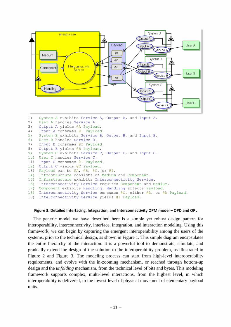
At the next modeling level, we delve deeper into the systems, components, and interfaces,
and focus on each payload and on each interaction concerning a payload. We express the
infrastructure’s seed-function – interconnectivity service, elaborate the infrastructure’s
components and media, and describe additional processes enabled thereby. We also express the
states in which the payload can be, and trace these states to the events of yielding and
consumption or reception of the payload by the various systems. We also define an
intermediate state when the payload is handled by the infrastructure or travels through it, and is
not held by any particular member system. These notions are demonstrated in Figure 3.
Once we have the interfacing processes defined, we can create various sequences, capturing
various scenarios required for interoperability at the system-of-systems level. Although
sequences can be captured at the third level, as demonstrated in as well, it is recommended to
avoid it at this point, and harness the complexity management mechanism for this purpose.
Scenarios may stem from various payload types and characterizations, member system
configurations, triggering events (e.g. user requests, timed tasks, or external/environmental
events), etc. The framework supports dedicated modeling of member systems and
infrastructure behavior vis-à-vis each relevant scenario, via multiple coordinated views and
in-zoomed diagrams. OPM’s complexity alleviation mechanism is a critical asset at this stage.

– 10 –
1) User A yields Payload. User B consumes Payload.
2) User B yields Payload. User C consumes Payload.
3) User C yields Payload. User A consumes Payload.
Figure 1. High-level Interoperability OPM Model – OPD and OPL
1) User A handles System A.
2) User B handles System B.
3) User C handles System C.
4) System A yields Payload. System A consumes Payload.
5) System B yields Payload. System B consumes Payload.
6) System C yields Payload. System C consumes Payload.
7) Infrastructure yields Payload. Infrastructure consumes Payload.
Figure 2. High-level Interconnectivity OPM Model – OPD and OPL
– 11 –
1) System A exhibits Service A, Output A, and Input A.
2) User A handles Service A.
3) Output A yields @A Payload.
4) Input A consumes @I Payload.
5) System B exhibits Service B, Output B, and Input B.
6) User B handles Service B.
7) Input B consumes @I Payload.
8) Output B yields @B Payload.
9) System C exhibits Service C, Output C, and Input C.
10) User C handles Service C.
11) Input C consumes @I Payload.
12) Output C yields @C Payload.
13) Payload can be @A, @B, @C, or @I.
14) Infrastructure consists of Medium and Component.
15) Infrastructure exhibits Interconnectivity Service.
16) Interconnectivity Service requires Component and Medium.
17) Component exhibits Handling. Handling affects Payload.
18) Interconnectivity Service consumes @C, either @B, or @A Payload.
19) Interconnectivity Service yields @I Payload.
Figure 3. Detailed Interfacing, Integration, and Interconnectivity OPM model – OPD and OPL
The generic model we have described here is a simple yet robust design pattern for
interoperability, interconnectivity, interface, integration, and interaction modeling. Using this
framework, we can begin by capturing the emergent interoperability among the users of the
systems, prior to the technical design, as shown in Figure 1. This simple diagram encapsulates
the entire hierarchy of the interaction. It is a powerful tool to demonstrate, simulate, and
gradually extend the design of the solution to the interoperability problem, as illustrated in
Figure 2 and Figure 3. The modeling process can start from high-level interoperability
requirements, and evolve with the in-zooming mechanism, or reached through bottom-up
design and the unfolding mechanism, from the technical level of bits and bytes. This modeling
framework supports complex, multi-level interactions, from the highest level, in which
interoperability is delivered, to the lowest level of physical movement of elementary payload
units.
– 12 –
4. Example: Health Services Interoperability
In this section, we briefly describe a simplified example of the interconnectivity and
interoperability challenge in the healthcare service system-of-systems. Hospitals, patients,
healthcare service providers (HSP), pharmacies, insurance companies, medical device
providers, health regulators, physicians and various healthcare workers provide and receive
medical services from one another. These include both informatical and physical services, and
involve handling, transferring, and storing various biomedical materials, pharmaceuticals,
patients’ blood and tissues, organs for transplant, and more. A top-level Object-Process
Diagram capturing all stakeholders (humans and organizations alike), key systems and
components, and the various payloads, is illustrated in Figure 4. It also shows the
interconnectivity infrastructure and the seed function it provides: Health Services
Interconnectivity, the enablers of interaction among the various stakeholders, and the exchange
of various payloads. While a distinctive interconnectivity infrastructure may not necessarily
exist as an independent entity, it is important to define it as a model entity nonetheless. Key
excerpts from the Object-Process Language textual description follow the diagram.
We now dive deeper into a simple subset of the domain, in which we want to capture the
ability of a patient to query and receive medical information through a mobile device,
especially regarding the patient’s blood tests, for instance. This example involves handling
both informatical and physical payloads. Interoperability in this case is the ability of various
participants – the patient, the nurse, and the laboratory worker – to interact in the physical and
digital media, in order to schedule a treatment involving a blood sample drawing, its analysis,
conveying the blood sample from the sampling location to the laboratory for analysis, and the
distribution of the results through cyberspace back to the patient’s mobile device.
The modelling can be done using top-down or bottom-up approaches. In the former, we first
define the main stakeholders, their media, and the exchanged payloads; then elaborate the
processes and services which enable the interaction, including those exhibited by the
interconnectivity infrastructure. In the bottom-up approach, we gradually construct an
integrated diagram of the domain, including stakeholders, systems, media, payloads, processes
and services. We then suppress the processes (and states) to create a concise view of the model.
While the top-down approach would be more intuitive, the latter would be more constructive.
We present the two synchronized models produced by OPCAT in Figure 5 and Figure 6. The
reader can try to infer the order of modelling, and follow his or her own preferred approach.

– 13 –
1) Healthcare Interconnectivity Infrastructure handles Health Service
Interoperability.
2) Health Service Interoperability requires Blood Bank, Laboratory,
Pharmaceutical Company, Health Service Regulator, Pharmacy, Hospital,
Health Services Provider (HSP), Medical Device, Medical Information
System, Ambulance, Physician, Guardian, Patient, Nurse, and Insurance
Company.
3) Health Service Interoperability affects Blood/ Tissue, Medical Record,
Medicine, Raw Material, and Money.
4) Patient, Physician, Nurse, and Guardian are Humans.
5) Health Services Provider (HSP), Hospital, Pharmacy, Insurance Company,
Pharmaceutical Company, Laboratory, and Blood Bank, are Organizations.
6) Medicine, Medical Record, Blood/ Tissue, Money, Raw Material, and Organ
are Payloads.
7) Medical Device, Medical Information System, and Ambulance are Systems.
Figure 4. Medical Interoperability and Interconnectivity
Figure 5. Medical Record and Blood Sample Interoperability - Concise View

– 14 –
Figure 6. Medical Record and Blood Sample Interoperability – Detailed View
This example demonstrates the ability to capture a simple, everyday process, such as a
patient receiving her blood test results – concealing complex integration and interaction among
various disparate organizations, users, and systems, including the exchange, processing, and
analysing of both information and physical payloads. The level of detail obtained in this
top-level illustration is not sufficient, and must be further elaborated and enhanced to include
all the devices required to safely and securely transfer the payloads from one point to another,
the media through which they are transferred, and the applicable conditions and constraints.
This is part of an on-going research on model-based risk-oriented design for interoperability in
the medical informatics domain.
5. Summary
This paper has introduced a model-based framework for the design of complex interactions
among disparate systems. The framework attempts to capture all levels of integration, from the
most immediate and technical interfacing to the most emergent and synergetic interoperability.
This framework provides an integration-centric perspective, which is much needed in
System-of-Systems integration programs, especially to those responsible for facilitating
interconnectivity infrastructure and enabling the interaction. The current literature consists of
theories and practices related to specific domains, e.g., aerospace & defense, manufacturing &
supply chains, and information technology.
Our method utilizes OPM – Object Process Methodology – as an underlying modeling
framework, which provides bimodal graphical and textual formalism. We employ existing
OPM mechanisms—in-zooming, unfolding and Suppression-Expression—and extend their
applicability, in order to support the unique aspects demonstrated in the modeling of
Systems-of-Systems in general, and SoS integration in particular. We directly capture

– 15 –
emergent properties and behaviors, as well as a top-to-bottom hierarchy of interaction aspects.
Furthermore, we support a common modeling notation derived from System-centered design
frameworks that are still practiced by experienced systems engineers.
The major contribution of this paper is the presentation of the I5 framework and its building
blocks and modeling notation. The I5 framework is purely semantic and generic; it does not
deal with technical aspects and issues arising from the physical nature of the interaction, the
media, or the type of the systems in question, e.g., its software and hardware. This framework
was intentionally developed to accommodate various domains and unify informatical and
physical integration modeling, which is a gap and a challenge in current modeling languages.
On the flip side, the framework does not specialize in a single type of systems, media, or
payloads, which might limits its immediate application.
We are currently studying several application domains, in order to demonstrate and prove
the generic applicability of our framework. Two of these domains are defense and health,
which was glimpsed in this paper. In the defense domain, we study the application to several
complex, large-scale, multidisciplinary defense systems, in the fields of enterprise C4ISR
interconnectivity, ballistic missile defense, and homeland security. We evaluate the
contribution of the I5
framework to the success and risk reduction of the integration process. In
the health domain, we study the applicability of our method in supporting privacy and
confidentiality assurance, while medical and personal information and substances related to the
patient are transferred among health organizations (e.g., health authorities, hospitals,
healthcare services, insurance companies), staff, medical devices (scanners, sensors, detectors,
and treating machinery) and medical records. We are seeking to extend the I5 application to the
energy and production domains.
This framework utilizes Object-Process Methodology for expressing its notation and
providing usable design products, but this framework’s notions and notation can be adapted in
various modeling languages. The importance of recognizing the infrastructure as a system in
its own right, and to properly model its form and function, are the key aspects of our
framework, and these can be implemented in various languages. OPM’s distribution is not as
wide as UML’s or even SysML’s, but its ever growing reputation, application, and
standardization are expected to enhance its dissemination. This work is part of a larger research
on the modeling and design of complex systems, especially in the presence of risk. Interfaces
and integration have been traditionally perceived as sources of risk, and integration risk
mitigation techniques are constantly sought for and tested.
Acknowledgements. The authors would like to thank the Bernard M. Gordon Center for
Systems Engineering at the Technion – Israel Institute of Technology, and to the
Technion-Cornell Innovation Institution at NYC, for funding this research. We would also like
to thank the anonymous referees and editors from INCOSE for very useful comments and
suggestions, which helped improve this paper.

– 16 –
References
Boehm, Barry. 2006. “Some Future Trends and Implications for Systems and Software
Engineering Processes.” Systems Engineering 9 (1): 1–19. doi:10.1002/sys.20044.
http://doi.wiley.com/10.1002/sys.20044.
Brooks, RT, and Andrew P Sage. 2006. “System of Systems Integration and Test.”
Information, Knowledge, Systems Management 5: 261–280.
http://iospress.metapress.com/index/QK67355P443165K0.pdf.
C4ISR Architecture Working Group. 1998. “Levels of Information Systems Interoperability
(LISI).” March.
Chen, David, Guy Doumeingts, and François B Vernadat. 2008. “Architectures for Enterprise
Integration and Interoperability: Past, Present and Future.” Computers in Industry 59 (7)
(September): 647–659. doi:10.1016/j.compind.2007.12.016.
http://linkinghub.elsevier.com/retrieve/pii/S0166361508000365.
Crawley, Edward, Olivier De-Weck, Steven Eppinger, Christopher Magee, Joel Moses,
Warren Seering, Joel Schindall, David Wallace, and Daniel Whitney. 2004. “Engineering
Systems Monograph.”
Dori, Dov. 2002. Object-Process Methodology: A Holistic Systems Approach. Object Process
Methodology - a Holistic Systems Paradigm. Springer.
Dori, Dov, Iris Reinhartz-berger, and Arnon Sturm. 2003. “Developing Complex Systems with
Object-Process Methodology Using OPCAT 1 The Basis : Object-Process Methodology”:
570–572.
Estefan, J A. 2007. “Survey of Model-based Systems Engineering (MBSE) Methodologies.”
Incose MBSE Focus Group 25.
Favre, L. 2003. UML and the Unified Process. IRM Press.
http://books.google.com/books?hl=en&lr=&id=ViLab3uCOy8C&oi=fnd&pg=PR7&dq
=UML+and+the+Unified+Process&ots=Ip8HeyaHGe&sig=dM4DKG_EQCDHwPijZP
4uy0nLLE0.
Harel, David, and Michal Politi. 1998. Modeling Reactive Systems with Statecharts: The
STATEMATE Approach. McGraw-Hill, Inc.
Jørgensen, HD, Tore Liland, and Stein Skogvold. 2011. “Aligning TOGAF and
NAF-Experiences from the Norwegian Armed Forces.” The Practice of Enterprise
Modeling: 131–146. http://www.springerlink.com/index/G108222N86N33674.pdf.
Lamparthaki, Fenareti, Soitiris Koussouris, Carlo Agostinho, Ricardo Jardim-Goncalves,
Yannis Charalabidis, and John Psarras. 2012. “Infusing Scientific Foundations into
Enterprise Interoperability.” Computers in Industry 63: 858–866.

– 17 –
Mordecai, Yaniv, Nimrod Focsenianu, and Liron Elzon. 2011. “Information Throughput Rate
Control in Central Interconnectivity Systems.” In 6th International Conference on
Systems Engineering. Herzeliyya, Israel: INCOSE IL.
Naudet, Yannick, Thibaud Latour, Wided Guedria, and David Chen. 2010. “Towards a
Systemic Formalisation of Interoperability.” Computers in Industry 61 (2) (February):
176–185. doi:10.1016/j.compind.2009.10.014.
http://linkinghub.elsevier.com/retrieve/pii/S0166361509002073.
Nof, S.Y., G. Morel, L. Monostori, a. Molina, and F. Filip. 2006. “From Plant and Logistics
Control to Multi-enterprise Collaboration.” Annual Reviews in Control 30 (1) (January):
55–68. doi:10.1016/j.arcontrol.2006.01.005.
http://linkinghub.elsevier.com/retrieve/pii/S136757880600006X.
Panetto, Hervé, Ricardo Jardim-Goncalves, and Arturo Molina. 2012. “Enterprise Integration
and Networking: Theory and Practice.” Annual Reviews in Control (October).
doi:10.1016/j.arcontrol.2012.09.009.
http://linkinghub.elsevier.com/retrieve/pii/S1367578812000442.
Parks, Charles M, David A Koonce, Luis C Rabeldo, Robert P Judd, and John A Sauter. 1994.
“Model-Based Manufacturing Integration: A Paradigm for Virtual Manufacturing
Systems Engineering.” Computers and Industrial Engineering 27 (94): 357–360.
Sage, Andrew P., and Charles L. Lynch. 1998. “Systems Integration and Architecting: An
Overview of Principles, Practices, and Perspectives.” Systems Engineering 1 (3): 176–
227. doi:10.1002/(SICI)1520-6858(1998)1:3<176::AID-SYS3>3.0.CO;2-L.
http://doi.wiley.com/10.1002/%28SICI%291520-6858%281998%291%3A3%3C176%3
A%3AAID-SYS3%3E3.0.CO%3B2-L.
Sharon, Amira, and Dov Dori. 2009. “A Model-Based Approach for Planning Work
Breakdown Structures of Complex Systems Projects.” In Proc. 14th IFAC Symposium on
Information Control Problems in Manufacturing.
http://iucontent.iu.edu.sa/scholars/workflow
development/A-Model-Based-Approach-for-Work-Breakdown-Structure-WBS-of-Com
plex-Systems-Projects-3.pdf.
Sheth, AP. 1998. “Changing Focus on Interoperability in Information Systems: From System,
Syntax, Structure to Semantics.” In Interoperating Geographic Information Systems, ed.
MF Goodchild, MJ Egenhoffer, R Fegeas, and CA Kottman. Kluwer.
http://knoesis.org/library/publications/pubs_1999.html.
Vernadat, François B. 2007. “Interoperable Enterprise Systems: Principles, Concepts, and
Methods.” Annual Reviews in Control 31 (1) (January): 137–145.
doi:10.1016/j.arcontrol.2007.03.004.
http://linkinghub.elsevier.com/retrieve/pii/S1367578807000132.
Williams, T J, P Bernus, J Brosvic, D Cben, G Doumeingts, L Nemest, J L Nevins, and B
Vallesplr. 1994. “Architectures for Integrating Manufacturing Activities and Enterprises.”
Control Engineering Practice 2 (6): 939–960.

– 18 –
Appendix A – OPM Notation
Entities
Name Symbol OPL Definition
Object
B is physical.
(shaded rectangle)
C is physical and
environmental (shaded
dashed rectangle)
An object is a thing that exists.
Process
E is physical
(shaded ellipse)
F is physical and
environmental (shaded
dashed ellipse)
A process is a thing that transforms
at least one object.
Transformation is object
generation or consumption, or effect –
a change in the state of an object.
State
A is s1.
B can be s1 or s2.
C can be s1, s2, or
s3.
s1 is initial.
s3 is final.
A state is situation an object can be
at or a value it can assume.
States are always within an object.
States can be initial or final.

– 19 –
Structural Links and Complexity Management
Name Symbol OPL Semantics
Fu
nd
amen
tal Stru
ctural R
elation
s
Aggregation-
Participation
A consists of B
and C.
A is the whole, B and C are
parts.
A consists of B
and C.
Exhibition-
Characterization
A exhibits B, as
well as C.
Object B is an attribute of A
and process C is its operation
(method).
A can be an object or a
process.
A exhibits B, as
well as C.
Generalizatio
n- Specialization
B is an A.
C is an A.
A specializes into B and C.
A, B, and C can be either all
objects or all processes.
B is A.
C is A.
Classification
-Instantiation
B is an instance
of A.
C is an instance
of A.
Object A is the class, for
which B and C are instances.
Applicable to processes too.
Unidirectional &
bidirectional
tagged structural
links
A relates to B.
(for
unidirectional)
A and C are
related.
(for
bidirectional)
A user-defined textual tag
describes any structural relation
between two objects or between
two processes.
In-zooming
A exhibits C.
A consists of B.
A zooms into B,
as well as C.
Zooming into process A, B is
its part and C is its attribute.
A exhibits C.
A consists of B.
A zooms into B,
as well as C.
Zooming into object A, B is
its part and C is its operation.

– 20 –
Enabling and Transforming Procedural Links
Name Symbol OPL Semantics
En
ablin
g lin
ks
Agent Link
A handles
B.
Denotes that the object is a
human operator.
Instrument
Link
B requires
A.
"Wait until" semantics: Process
B cannot happen if object A does
not exist.
State-
Specified
Instrument
Link
B requires
s1 A.
"Wait until" semantics: Process
B cannot happen if object A is not
at state s1.
Tran
sform
ing
link
s
Consumption
Link
B consumes
A.
Process B consumes Object A.
State-
Specified
Consumption
Link
B consumes
s1 A.
Process B consumes Object A
when it is at State s1.
Result Link
B yields A. Process B creates Object A.
State-
Specified
Result Link
B yields s1
A.
Process B creates Object A at
State s1.
Input-Output
Link Pair
B changes
A from s1 to
s2.
Process B changes the state of
Object A from State s1 to State s2.
Effect Link
B affects A. Process B changes the state of
Object A; the details of the effect
may be added at a lower level.

– 21 –
Event, Condition, and Invocation Procedural Links
Name Symbol OPL Semantics
Instrument
Event Link
A triggers B.
B requires A.
Existence or generation of
object A will attempt to trigger
process B once. Execution will
proceed if the triggering failed.
State-Specifi
ed
Instrument
Event Link
A triggers B
when it enters s1.
B requires s1 A.
Entering state s1 will attempt to
trigger the process once.
Execution will proceed if the
triggering failed.
Consumption
Event Link
A triggers B.
B consumes A.
Existence or generation of
object A will attempt to trigger
process B once. If B is triggered, it
will consume A. Execution will
proceed if the triggering failed.
State-Specifi
ed
Consumption
Event Link
A triggers B
when it enters s2.
B consumes s2
A.
Entering state s2 will attempt to
trigger the process once. If B is
triggered, it will consume A.
Execution will proceed if the
triggering failed.
Condition
Link
B occurs if A
exists.
Existence of object A is a
condition to the execution of B.
If object A does not exist, then
process B is skipped and regular
system flow continues.
State-Specifi
ed
Condition
Link
B occurs if A is
s2.
Existence of object A at state s2
is a condition to the execution of
B.
If object A does not exist, then
process B is skipped and regular
system flow continues.
Invocation
Link
B invokes C. Execution will proceed if the
triggering failed (due to failure to
fulfill one or more of the
conditions in precondition set).

– 22 –
6. Biography
Dov Dori is Information and Systems Engineering Professor and Head of
the Enterprise System Modeling Laboratory at the Faculty of Industrial
Engineering and Management, Technion, Israel Institute of Technology,
and Research Affiliate at the Engineering Systems Division,
Massachusetts Institute of Technology, where he lectures on a regular
basis. Between 1999–2001 and 2008–2009 he was Visiting Professor
with the Engineering Systems Division, the Department of Aeronautics
and Astronautics, and Sloan Business School at MIT. His research
interests include conceptual modeling of complex systems, systems
architecture and design, and software and systems engineering. Professor Dori has invented
and developed Object-Process Methodology (OPM), presented in his 2002 book. He won the
Technion Klein Research Award for OPM, the Hershel Rich Innovation Award for OPCAT, the
OPM supporting software, and the Dudi Ben Aharon Research Award for Document Image
Understanding. Professor Dori has founded OPCAT Ltd., which develops an OPM modeling
support environment. He initiated and headed the series of international conferences on
Model-Based Systems Engineering held at Technion, Israel, in 2007 and 2009, and at George
Mason University, VA, in 2010. Professor Dori has authored over 200 publications. He is a
Fellow of the International Association for Pattern Recognition, a Senior Member of IEEE
and ACM, and a fellow of INCOSE.
Yaniv Mordecai holds a B.Sc. and a M.Sc. (with honours) in Industrial
Engineering & Management from Tel Aviv University, Israel (2002, 2010).
He is currently a Ph.D. candidate at the Technion – Israel Institute of
Technology. He served as an officer in the Israeli Air-Force where he
practiced project management and systems engineering in large scale
projects for several years. He currently works for Elbit Systems, as a
Command & Control system engineer. His research interests include
Systems Engineering and Design, Model-Based Systems Engineering, Risk
Analysis, Interconnectivity and Interoperability Analysis, Operations
Research and Decision Making.