Embed Size (px)
Citation preview

Introdu
AR0300 - Urban Body
ction to Soft and RigidBody Dynamics in Maya
© UC Berkeley Undergraduate Graphics Group
Technisch&informaticaOntwerp

Contents:
Introduction . . . . . . . . . . . . . . . . . . . . . . . . . . . . . . . . . . . . . . . . . . . . . . . . . . . . . . . . . . 1
Part I: Dynamics Basics . . . . . . . . . . . . . . . . . . . . . . . . . . . . . . . . . . . . . . . . . . . . . . . . . 2Why Use Maya Dynamics? . . . . . . . . . . . . . . . . . . . . . . . . . . . . . . . . . . . . . . . . . . . . . . . . . . . . . 2The Big Picture . . . . . . . . . . . . . . . . . . . . . . . . . . . . . . . . . . . . . . . . . . . . . . . . . . . . . . . . . . . . . . 3Types of Bodies . . . . . . . . . . . . . . . . . . . . . . . . . . . . . . . . . . . . . . . . . . . . . . . . . . . . . . . . . . . . . 3Creating and Working With Rigid Bodies . . . . . . . . . . . . . . . . . . . . . . . . . . . . . . . . . . . . . . . . . 4Creating and Working With Soft Bodies . . . . . . . . . . . . . . . . . . . . . . . . . . . . . . . . . . . . . . . . . . 5Applying Fields . . . . . . . . . . . . . . . . . . . . . . . . . . . . . . . . . . . . . . . . . . . . . . . . . . . . . . . . . . . . . . 5Applying Constraints . . . . . . . . . . . . . . . . . . . . . . . . . . . . . . . . . . . . . . . . . . . . . . . . . . . . . . . . . 5Applying Springs . . . . . . . . . . . . . . . . . . . . . . . . . . . . . . . . . . . . . . . . . . . . . . . . . . . . . . . . . . . . 6
Part II: Using Rigid Bodies to Simulate a Bowling Scene . . . . . . . . . . . . . . . . . . . . . . . 7Setting Up the Geometry . . . . . . . . . . . . . . . . . . . . . . . . . . . . . . . . . . . . . . . . . . . . . . . . . . . . . . 7Making Rigid Bodies . . . . . . . . . . . . . . . . . . . . . . . . . . . . . . . . . . . . . . . . . . . . . . . . . . . . . . . . . 7Applying Gravity . . . . . . . . . . . . . . . . . . . . . . . . . . . . . . . . . . . . . . . . . . . . . . . . . . . . . . . . . . . . 8Making Adjustments . . . . . . . . . . . . . . . . . . . . . . . . . . . . . . . . . . . . . . . . . . . . . . . . . . . . . . . . . 9
Part III: Approximating Complex Shapes With Simple Shapes for Dynamics . . . . . 10Setting Up the Scene . . . . . . . . . . . . . . . . . . . . . . . . . . . . . . . . . . . . . . . . . . . . . . . . . . . . . . . . 10Approximating the Sculpture . . . . . . . . . . . . . . . . . . . . . . . . . . . . . . . . . . . . . . . . . . . . . . . . . . 10Freezing Transformations . . . . . . . . . . . . . . . . . . . . . . . . . . . . . . . . . . . . . . . . . . . . . . . . . . . . 11Rigging the Scene for Dynamics . . . . . . . . . . . . . . . . . . . . . . . . . . . . . . . . . . . . . . . . . . . . . . . 11Setting the Sculpture to Inherit Transformation . . . . . . . . . . . . . . . . . . . . . . . . . . . . . . . . . . . 11Making Adjustments . . . . . . . . . . . . . . . . . . . . . . . . . . . . . . . . . . . . . . . . . . . . . . . . . . . . . . . . 12Hiding the Cube . . . . . . . . . . . . . . . . . . . . . . . . . . . . . . . . . . . . . . . . . . . . . . . . . . . . . . . . . . . . 13Baking . . . . . . . . . . . . . . . . . . . . . . . . . . . . . . . . . . . . . . . . . . . . . . . . . . . . . . . . . . . . . . . . . . . . 13
Part IV: Using Springs to Create a Hand-held Camera Rig . . . . . . . . . . . . . . . . . . . . 14Setting up the Scene . . . . . . . . . . . . . . . . . . . . . . . . . . . . . . . . . . . . . . . . . . . . . . . . . . . . . . . . . 14Attaching Springs . . . . . . . . . . . . . . . . . . . . . . . . . . . . . . . . . . . . . . . . . . . . . . . . . . . . . . . . . . . 15Adjusting the Springs and Particle . . . . . . . . . . . . . . . . . . . . . . . . . . . . . . . . . . . . . . . . . . . . . . 16Constraining the Camera to the Particle . . . . . . . . . . . . . . . . . . . . . . . . . . . . . . . . . . . . . . . . . 17Hiding the Cube and Particle . . . . . . . . . . . . . . . . . . . . . . . . . . . . . . . . . . . . . . . . . . . . . . . . . . 19
Part V: Using Soft Bodies to Simulate a Waving Flag . . . . . . . . . . . . . . . . . . . . . . . . . 20Setting Up the Scene . . . . . . . . . . . . . . . . . . . . . . . . . . . . . . . . . . . . . . . . . . . . . . . . . . . . . . . . 20Goals and Creating the Soft Body . . . . . . . . . . . . . . . . . . . . . . . . . . . . . . . . . . . . . . . . . . . . . . 20Applying Fields . . . . . . . . . . . . . . . . . . . . . . . . . . . . . . . . . . . . . . . . . . . . . . . . . . . . . . . . . . . . . 21Attaching the Flag to the Pole . . . . . . . . . . . . . . . . . . . . . . . . . . . . . . . . . . . . . . . . . . . . . . . . . 21Making Adjustments . . . . . . . . . . . . . . . . . . . . . . . . . . . . . . . . . . . . . . . . . . . . . . . . . . . . . . . . 23

-1-
Introduction
These tutorials do not assume any prior experience with Maya dynamics. However, they do assume abasic fluency with the Maya interface. Only basic skills are needed, such as selecting, moving, scaling,and rotating objects, creating polygon and NURBS primitive objects, familiarity with the Outline,Channels Box, and Attribute Editor, and alt-clicking to pan, zoom, and rotate the viewports.
Words in Arial Typeface refer to specific keywords that are present in the actual Maya interface that youcan look for when trying to follow an instruction in the tutorial. Words in underlined type are conceptualideas, but are also names of types of objects that are used within Maya.
Part I of this tutorial section provides an overview on how the Maya Dynamics system is designed andsome general techniques for using it in your scenes. Parts II, III, IV and V provide step-by-step tutorialson specific applications of dynamics. Each of those scenes has an accompanying Maya Binary file to usewhile doing the tutorial. However, the concepts in the tutorials can be applied to any relevant scene fileof your choosing.
These tutorials do not deal with two other important aspects of dynamics, Particle Systems and Effects.However, particles are used briefly in Parts IV and V. We explain enough about particles in thesesections for you to understand their role and how to manipulate them in those contexts, but seek aParticles tutorial for a conceptual understanding of Particles, as well as some more sophisticatedapplications of that vastly powerful part of Maya Dynamics.
Enjoy!

-2-
Part I: Dynamics Basics
Why Use Maya Dynamics?
Some of the main reasons include:• Modeling naturalistic motion that is difficult to achieve with keyframing• Modeling complicated motion involving many elements• Automating repetitive motion or motion that is not primary to the scene
For example:• Modeling nails falling on a table• Simulating glass shattering• Animating the motion of the antenna of a moving car

-3-
The Big Picture
Dynamics objects are either Rigid Bodies or Soft Bodies, which interact with each other under theinfluence of Fields, which affect their motion. Additionally, more complex motion can be simulated byrestricting the motion of these bodies, using either Springs or Constraints.
Types of Bodies
There are two types of objects in Maya Dynamics:
• Rigid Bodies are solid objects that do not deform, and are used for most straightforward applications of dynamics.Rigid bodies come in two forms:• Active Rigid Bodies are influenced by forces in your scene as well as interactions with
other rigid bodies. However, they cannot be user-controlled in any significant way, otherthan their initial placement.
• Passive Rigid Bodies can influence active rigid bodies, but they themselves are notinfluenced by other bodies or forces in your scene. They can also have user-controlledmotion, such as through key frames.
For example, if you were simulating a ball falling onto the street, the ball would be an active rigidbody and the street a passive rigid body. The ball will have its motion determined by agravitational force, as well as by its collision with the street. The street, however, should notmove at all when the ball collides with it, nor should it feel the influence of gravity, so it shouldbe made a passive rigid body. However, it is crucial to remember to make the street into a rigidbody, since otherwise the ball will fall right through it.
• Soft Bodies can be thought of as deformable skin, and will change shape when influenced byforces or collisions. When you create a soft body, you can think of what Maya does as turningthe original shape into a set of particles, whose positions are then affected by fields andconstraints. Then at each frame Maya determines the current shape of the object by “connectingthe dots,” constructing what the shape should look like from the relative orientations of all theparticles.
You must convert geometry into dynamics objects before they can be used with dynamics. Geometrythat is not converted to these objects will be ignored by the dynamics engine. Dynamics objects can becreated from NURBS or Polygon objects.

-4-
Creating and Working With Rigid Bodies
Important: You should only use simple objects as rigid bodies in order to keep calculation times reasonable. Otherwise,dynamics calculation times are either frustratingly high or will make Maya crash. If the objects you are modeling arecomplicated, use a technique of approximating those shapes with simple geometry which will be used in the dynamicssimulation. Then, parent your complicated geometry to the simple shapes. See Part III for a detailed example.
Activate the Dynamics menu set in the Maya interface.
Select an object or group of objects, and go to the Soft/Rigid Bodies menu, choose either Create ActiveRigid Body or Create Passive Rigid Body, and click the square to the right to bring up the creation dialogbox. (Both active and passive bodies bring up the same dialog box, with the only difference being thatthe Active box is only checked if you chose Create Active Rigid Body.) Modify the settings to best matchthe object you are modeling and click Create.
Once created, Active Rigid Bodies cannot be keyframed, though Passive Rigid bodies can. Your primarymeans of controlling Active Rigid Bodies are through Fields, Constraints, and Springs. However, shouldyou need greater control over your Active Rigid Bodies, you can keyframe their Active attribute. Thesemeans you can turn their Active status off for a period of time, keyframe their motion during this period,and then make them Active once again when you want them to respond to dynamics.

-5-
Creating and Working With Soft Bodies
Select an object and go to the Soft/Rigid Bodies menu (again making sure that the Dynamics menu setis active), and click the square next to Create Soft Body. Under Creation Method, you can choosewhether to make the selected object a soft body, or instead make a duplicate of the object and makeeither the original or duplicate object soft. If you make a duplicate, you can choose whether or not tomake the non-soft object a Goal. A soft body will be influenced to take the shape of its goal object, andyou can set how strongly the soft body tries to achieve its goal shape by adjusting its Goal Weight in theAttribute Editor or Channels box. The Weight setting in the Soft Options box determines how easy ordifficult it is to deform the soft body from its goal shape.. When you are satisfied with the settings, clickCreate.
Applying Fields
Applying fields to Soft and Rigid Bodies is a simple task. Simply select the body or bodies you want tobe affected by the field, go into the Field menu, and choose your desired field. This creates a single nodefor that field, which you can edit later. This is convenient, since editing the single field node will changethe way the field acts on each of the objects bound to it. You can apply as many fields as you want toeach object.
Applying Constraints
Constraints can only be applied to Rigid Bodies. To apply a constraint, again simply select the body orbodies you want, go to the Soft/Rigid Bodies menu, and choose the box next to Create Constraint.Once in the Constraint Options window, there will be a dropdown menu called Constraint Type. Thereare four main types of constraints that are commonly used:
• Nail - A nail constraint sets a point in space about which your rigid body can rotate. Thelength from this pivot point to your object remains fixed. You would use a nailconstraint if you wanted to set the pivot point of a pendulum.
• Pin - You must have two bodies selected in order to make a pin constraint. Essentiallycreates a rigid rod connecting the two objects, with a joint in the middle of it. If youwere making a mobile, you could connect the dangling objects to the base of the mobileby using pin constraints.

-6-
• Hinge - Creates an axis through your object about which the object can rotate. That axisremains fixed in space. That is, if you had a cube with a hinge constraint runningthrough its center, even you had a gravity field applied to the cube, it will not fall, sinceit is held in place by the hinge.
• Spring - A spring constraint is similar to a nail constraint, except that the distance fromthe pivot point to your object can stretch and contract. You can adjust the stiffness,damping, and rest length of a spring constraint.
By default, all constraints act on the center of mass of your object, but you can manually change thecenter of mass of any body, and therefore change the point at which the constraints act.
Applying Springs
Springs are slightly similar to spring constraints, but are much more versatile and powerful. Springs canbe attached to the sub-components of almost any object. For example, individual particles of softbodies, poly vertices, NURBS control vertices, and so on. The sub-components do not need to be partof a soft or rigid body. This means that you could, for example, create springs between the particles ofa soft body cloth and the vertices of a poly cube that is not a dynamics object. This is especially handywhen you want to create springs to constrain a dynamics object to another object that you havekeyframe-animated.

-7-
Part II: Using Rigid Bodies to Simulate a BowlingScene
This tutorial is a simple introduction to applying dynamics to existing geometry in your scene in orderto easily produce realistic animation.
Setting Up the Geometry
The included scene is ready to have dynamics applied to it and doesn’t require any additional geometry.It consists of 10 bowling pins arranged in the usual triangle, placed on a thin plane. The pins areapproached by a steep, curved ramp which the ball will roll down to gain momentum. This is probablythe simplest setup for a bowling scene, but feel free to create your own geometry or expand on thisscene.
Making Rigid Bodies
We need to convert all the geometry in our scene into rigid bodies. We want the ball and the pins to beactive rigid bodies, since we’d like them to collide with each other and respond to a gravitational force.We want the plane and the ramp to be passive rigid bodies, since we need them to act as solid groundfor the ball and pins, but they need to remain fixed in place when they are collided with.
Select all the bowling pins, using the marquee tool or the outline, and go to the Soft/Rigid Bodiesmenu, and choose the box next to Create Active Rigid Body. When the Rigid Options windowcomes up, choose Edit, Reset Settings to reset to the default settings, and then just choose Create.We’ll adjust the settings later if need to after we watch the animation.

-8-
Now select the ball and again make it an active rigid body just as we did with the pins. Lastly, select theramp and the plane, and go to the Soft/Rigid Bodies menu, and click the box next to Create PassiveRigid Body. Once again, choose Edit, Reset Settings and then click Create.
Applying Gravity
Adding forces to a scene is an easy step. Select all the pins and the ball, and go to the Fields menu, andchoose the box next to Gravity. Once again, reset the settings and click create. The default settingsshould be sufficient for our gravity field.

-9-
Making Adjustments
The scene is now completely rigged and is ready to be played back. We nowjust need to adjust the dynamics settings to get realistic-looking motion. Goahead and play back the animation and watch closely as the ball strikes thepins. The pins fall, but the ball gets stopped completely, not at all what we’dexpect in real bowling. But when we accepted the default settings when wemade the ball a rigid body, we left its mass the same as the masses of the pins.We need to make the ball more massive so it’ll strike the pins with greatermomentum. Select the ball and bring up the channels box. Look for the fieldthat says Mass and bump up its value to around 50. Play back the animationagain and notice that the collision is much more realistic. The pins go flying,and the ball goes pretty much straight through. But the ball bounces quite abit, so go ahead and turn down its Bounciness to around 0.1.
The collision now looks pretty realistic. Feel free to play around with theother attributes to get the look you really like. Then, make sure to playblastyour scene (Window, Playblast*) to see how things look in real time. Often,the playback speed in Maya is very different from real time, since Maya has tocalculate the dynamics on the fly, which can slow down the playback speed,though with very simple dynamics scenes, the playback can actually be fasterthan real time.
*If you are using Windows XP, make sure that your display settings are set to Windows Classic mode. Otherwise, Mayawill crash when you try to playblast. You can adjust this setting by right-clicking on the desktop and choosingProperties. Then click the Appearance tab, click the drop-down menu under Windows and buttons andchoose Windows Classic Style.
-10-
Part III: Approximating Complex Shapes withSimple Shapes for Dynamics
Maya dynamics is very effective with simple geometry. However, very rarely will your scene only requireyou to use dynamics with spheres and cubes and the like. Not to worry though–there is a simpletechnique that allows you to use nearly any geometry in a dynamics simulation.
The basic idea is to create simple geometry that approximates the shape of the geometry that you actuallywant to use. You will then use the simple geometry in the dynamics simulation, and then have thecomplex geometry inherit the transformations of the simple geometry.
Setting Up the Scene:
For this example, we’re going to simulate a piece of corporate art crashing to the ground. And to makeit satisfying, we’re going to use a simple model of the infamous Enron corporate logo. However, feelfree to use any geometry that you’d like.
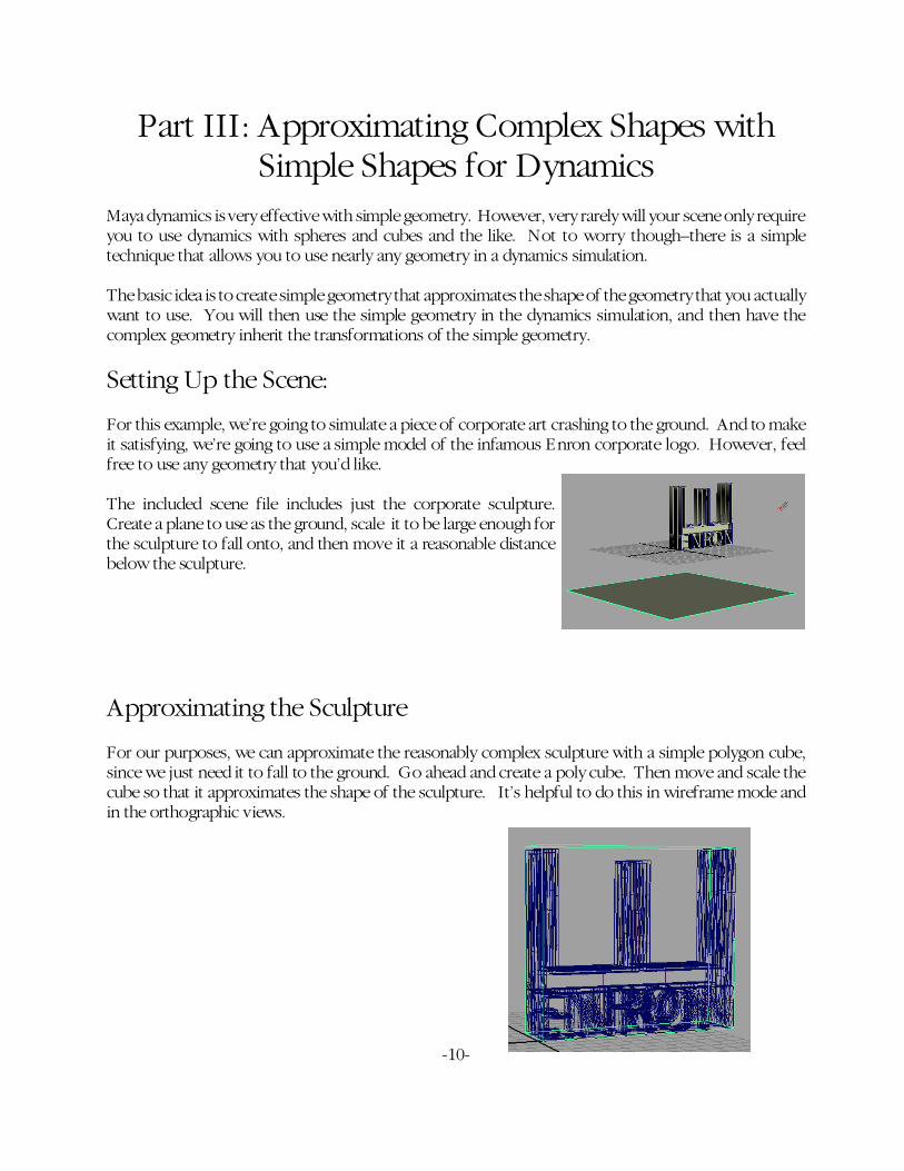
The included scene file includes just the corporate sculpture.Create a plane to use as the ground, scale it to be large enough forthe sculpture to fall onto, and then move it a reasonable distancebelow the sculpture.
Approximating the Sculpture
For our purposes, we can approximate the reasonably complex sculpture with a simple polygon cube,since we just need it to fall to the ground. Go ahead and create a poly cube. Then move and scale thecube so that it approximates the shape of the sculpture. It’s helpful to do this in wireframe mode andin the orthographic views.
-11-
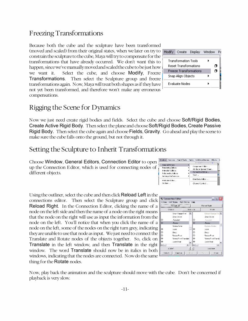
Freezing Transformations
Because both the cube and the sculpture have been transformed(moved and scaled) from their original states, when we later on try toconstrain the sculpture to the cube, Maya will try to compensate for thetransformations that have already occurred. We don’t want this tohappen, since we’ve manually moved and scaled the cube to be just howwe want it. Select the cube, and choose Modify, FreezeTransformations. Then select the Sculpture group and freezetransformations again. Now, Maya will treat both shapes as if they havenot yet been transformed, and therefore won’t make any erroneouscompensations.
Rigging the Scene for Dynamics
Now we just need create rigid bodies and fields. Select the cube and choose Soft/Rigid Bodies,Create Active Rigid Body. Then select the plane and choose Soft/Rigid Bodies, Create PassiveRigid Body. Then select the cube again and choose Fields, Gravity. Go ahead and play the scene tomake sure the cube falls onto the ground, but not through it.
Setting the Sculpture to Inherit Transformations
Choose Window, General Editors, Connection Editor to openup the Connection Editor, which is used for connecting nodes ofdifferent objects.
Using the outliner, select the cube and then click Reload Left in theconnections editor. Then select the Sculpture group and clickReload Right. In the Connection Editor, clicking the name of anode on the left side and then the name of a node on the right meansthat the node on the right will use as input the information from thenode on the left. You’ll notice that when you click the name of anode on the left, some of the nodes on the right turn grey, indicatingthey are unable to use that node as input. We just need to connect theTranslate and Rotate nodes of the objects together. So, click onTranslate in the left window, and then Translate in the rightwindow. The word Translate should now be in italics in bothwindows, indicating that the nodes are connected. Now do the samething for the Rotate nodes.
Now, play back the animation and the sculpture should move with the cube. Don’t be concerned ifplayback is very slow.

-12-
Making Adjustments
The bulk of the scene is done. We’ve rigged our geometry for dynamics and set the sculpture to inheritits transformations from the cube. All that’s left is tweaking the animation until it’s to our liking.
The playback with the sculpture constrained to the cube was to slow, so go back into the ConnectionEditor and disconnect the Translate and Rotate nodes, by once again clicking Translate in the leftwindow, and then Translate in the right window, and the same process for Rotate. Now we’ll justmake adjustments to the cube, and then when we’re satisfied we can reconnect the sculpture.
The way the sculpture falls is pretty boring, and not realistic at all. We want it to seem like this corporatestatue weighs an enormous amount. So, let’s give the rigid body some more mass, and rotate the cubea bit so it’s fall is more exciting.
Select the cube and open up the Channels Box.. Increase its mass to about500, and decrease its bounciness to about 0.2. Play back the animation andsee if you like it. Keep in mind that the animation may be playing faster orslower than real time. We’ll playblast in a second to see how the animationreally looks.
Now, rotate the cube a bit so that it’s bottom face is no longer parallel with the ground. Experiment withdifferent values to try to get the cube to fall onto one edge, and then just barely topple over onto theground. This will help give the impression that the sculpture weighs a lot. Move your perspective fairlyclose to the ground and zoom in pretty tightly, which help give an impression of size.
Now, we’ll want to make a playblast to see how this really looks in real time.Choose Window, Playblast, and click the box to bring up the settingswindow. Decide what resolution you’d like, and whether or not you want tosave the playblast to a file. Then click Playblast, wait for Maya to do thework, and watch your scene.
NOTE: If you are using Windows XP, make sure that your display settings are set toWindows Classic mode. Otherwise, Maya will crash when you try to playblast. You canadjust this setting by right-clicking on the desktop and choosing Properties. Then clickthe Appearance tab, click the drop-down menu under Windows and buttonsand choose Windows Classic Style.
When you are satisfied with how the animation looks, just go back and follow the steps on the previouspage to once again set the sculpture to inherit transformations from the cube.

-13-
Hiding the Cube
Obviously, when you render, you only want to see the sculpture, not the cube. So, just select the cubeand choose Display, Hide, Hide Selection, and the cube will be hidden from all the viewports, as wellas when you render. To get the cube back later on if you wanted to make adjustments, just select thecube in the Outliner, and choose Display, Show, Show Selection.
Baking
When you are completely satisfied with your scene and don’t want to make any more dynamics changes,you should do a Bake. Baking translates the motion of your objects into keyframes, instead of calculatingit on the fly using a dynamics simulation. It’s important to Bake once you’re satisfied, because things youdo with dynamics later in your scene may inadvertently affect what you’ve previously done. However,if your animation is Baked, it is now keyframe-animated, and will not be affected by dynamics at all.
Select the Sculpture group and choose Edit, Keys, Bake Simulation, and click the box to bring up thesettings window.
You can use the default options, but the value to pay attention to is Sample by. This determines afterhow many frames Maya will make a keyframe. A smaller value means a more precise sample ofdynamically simulated animation, but many more keyframes. A larger value will give a less precisesample, but far less keyframes, which would make it easier to edit the animation later should you wantto do that. You should choose this value based on the specific animation in your scene, determining howprecise a sample you really need. For this scene, sampling every 5-10 frames is perfectly adequate.However, in scenes where objects are moving fast, you may want to sample more often, otherwise youmay find that objects that were meant to collide don’t actually collide, or similar problems.
Now that your animation is baked, you can continue to work on other parts of the scene withoutworrying about affecting that animation.

-14-
Part IV: Using Springs to Create a Hand-heldCamera Rig
This is a simple method for using springs to created a camera rig that gives an effective hand-held look.However, this particular method only allows for control over the camera's translation. Creating a rig thatallows for translation and rotation can be accomplished using similar methods, but is more complex.This method is adapted from the Gnomon Dynamics XI tutorial.
Setting Up the Scene:
Create your own backdrop, or use the included landscape scene.
Create a polygon cube and scale it so that it is large enough to easily contain a camera. Work inwireframe mode so that you can see inside of the cube.
You can create a camera by going to the Create menu, choose Cameras, and then just Camera. Thiscreates a camera with just one node that you can control, which is sufficient for this project since we’reonly concerned with the translation of the camera.
Go to the Particles menu and choose the Particle Tool. Click once anywhere in the scene to createa particle. Then select the move tool and go to Modify, Center Pivot to place the pivot in the centerof the particle.

-15-
Next, we'll change how the particle displays so it's easier to see. Open theChannels Box and look for the field that says Particle Render Type. Clickthe dropdown menu and choose Spheres.
Now use the orthographic views to move the particle into the center of yourcube.
Attaching Springs
Now we're going to attach springs between the particle and the vertices of the cube.We need to change our selection mode to easily be able to select polygon verticesand particles. Click the button that activates Select by Component Type mode,and then right-click the square that is two icons to the right. When you hold downthe right mouse button, a menu comes up showing you the different types of pointsthat can be selected. Check or uncheck the boxes until only Poly Vertices andParticles are checked.
Marquee drag around the cube and the particle once, and they will turn blue to indicate that theircomponents are now able to be selected. Marquee drag around both the cube and the particle a secondtime, and now the particle and the poly vertices will turn yellow to indicate that they are selected.

-16-
Go to the Soft/Rigid Bodies Menu, and click the box next to Create Springs. Use the defaultsettings, but choose All for the Creation Method, and check the box next to Set Exclusive. UsingSet Exclusive means that springs will only be created between the particle and the vertices, but notbetween vertices and other vertices.
Click the Select by Object Type button to return to the familiar selection mode.
Now, select the cube and use keyframes to animate some movement of the cubearound the scene. Play the animation and you should see that the particleroughly follows the motion of the cube, but that it bobs back and forth. We’lladjust the spring and particle settings so that it doesn’t bob so much.
Adjusting the Springs and Particle
Select just the particle and open the channels box. Look for the field that saysConserve and notice that its current value is 1. Conserve is a value between 0and 1 and represents how much momentum is conserved by a particle.Changing the Conserve usually has very pronounced effects, and adjusting it byeven a few hundredths can be significant. Let’s set the Conserve to 0.95. Playback the animation and notice that the particle’s motion is now less dramatic.However, we’d like it to more closely follow the motion of the cube, which we’llachieve through adjusting the spring settings.

-17-
Select just the spring node, either in the workspace or in the outliner (it’s ofteneasier to select springs using the outliner). Again, go to the Channels Box, andlook for the fields Stiffness and Damping. Play around with increasing bothvalues until you get motion that you like. Stiffness controls how strongly thespring pulls, and can have an extensive range of values, from small decimals tobig integers. Damping controls how much energy is lost by the spring, and cantake on an extensive range of values, but most commonly will have values ofsmall decimals or small integers. Choose any values that you like, or try astiffness of 10 and damping of 0.5, which work well for this example.
Constraining the Camera to the Particle
Manually move the camera to where the particle is, and then orient the camera so it points towards thelandscape. With the camera selected, right-click in the perspective view, and then hold spacebar to bringup the marking menu. Choose Panels, Look Through Selected to look through the camera andmake sure that you have a good view of the landscape (if you aren’t in wireframe mode, press 4 on thekeyboard to get into wireframe mode so that you can see through the cube). If you want to return to theperspective view, bring the marking menu back up and choose Panels, Perspective, persp.
Now we’ll constrain the camera to the particle by using the Connection Editor to make one of theparticle’s nodes give its information to the translation node of the camera. Go to Window, GeneralEditors, Connection Editor.

-18-
Select the particle, and then click Reload Left in the Connection Editor. The left half the editor shouldrefresh with a list of nodes. Then select the camera and click Reload Right in the Connection Editorand the right half should refresh. Clicking the name of a node in the left half of the connection editorchooses a node that you’d like to output information from. Clicking the name of a node in the right halfchooses a node to receive as input information from the node in the left half. Once a node in the lefthalf is clicked, some nodes in the right half may turn grey, indicating that they are not available to receiveinformation from that output node. Any node still in black print is available to receive input. Nodes initalics indicate that those nodes are already connected. We’re going to connect the Center node of theparticle to the Translate node of the camera, so click the word Center in the left half and then theword Translate in the right half.
Now, when you play the animation, the camera should move in sync with the particle. Thus, it willmimic the rough, jiggly, more naturalistic motion of the particle. Feel free to look through the cameraagain to see what kind of motion you’re getting. Then, you can go back and make adjustments to thespring and the particle as you see fit. It is highly recommended to playblast at this point, since theplayback speed may not be at all indicative of real time, which is essential for seeing how natural thecamera’s motion really looks.

-19-
Hiding the Cube and Particle
Lastly, we need to hide the cube and the particle so that we can see the landscape instead of the insideof the cube or particle when we render or playblast. Select the particle, open up the Channels Box andgo back to the field called Particle Render Type, and change it to Points. We’ll have to make atransparent shader for the cube. Open up the Hypershade editor (Window, Rendering Editors,Hypershade). Right-click in the workspace under the Materials tab and choose Create, Materials,Lambert. Double-click on the Lambert material you just created to bring up the Attribute Editor. Dragthe Transparency slider all the way to the right. Select the cube and then right-click the Lambertmaterial in the Hypershade window and choose Assign Material to Selection. Now you’ll be able tolook through the cube when in a shaded display mode.
That’s it! Try playing around with constraining objects to particles for other applications of naturalisticmotion.

-20-
Part V: Using Soft Bodies to Simulate a WavingFlag
Setting Up the Scene
The included scene file includes a NURBS cylinder which will be our flag pole, and a NURBS planewhich will be the flag itself.
We’re going to turn our NURBS plane into a soft body. Essentially, what Maya will be doing is turningthe object in a set of particles. Then, we can apply fields and deformers to the soft body, which will inturn cause each particle to transform. Then, at each frame Maya looks at the relative positions of eachof the particles and determines what the shape should look like. Having more control vertices meansthere will be more particles when we create a soft body, allowing the plane to deform in more complexways.
So, let’s give the plane some more control vertices first by selecting the plane,and then opening up the Channels Box. Under Inputs, clickmakeNurbPlane1 to bring up the creation values for the plane. Let’s setboth Patches U and Patches V to 5 to give us a reasonable number of controlvertices to work with.
Goals and Creating the Soft Body
With the plane selected, choose Soft/Rigid Bodies, Create Soft Body, and click the box to bring upthe settings window. In the Soft Options window, you have three choices under Creation Options.Choose Duplicate, Make Original Soft, and then check the boxes next to Hide Non-Soft Objectand Make Non-Soft a Goal.
As described in Part I, a soft body tries to maintain the shape of its goal object. By making a duplicateplane a goal object for the flag, we’re ensuring that our soft body flag will generally maintain itsrectangular shape, instead of getting seriously deformed. The Goal Weight determines how strongly thesoft body tries to maintain its goal shape. We’ll leave it at the default of 0.5 for now, since we can alwaysadjust it later. After you click Create, Maya will create a duplicate NURBS plane, and will create aParticle Object, which gets parented to the original NURBS plane.
-21-
Applying Fields
Now that we have our soft body, we want to apply some fields to it to try to simulate realistic motion.We’ll start by creating some wind. Select either the soft body plane or its particle object and chooseFields, Air, and click the box to bring up the options window. Click on Wind, and then change thevalue of Direction X to 1, and the value of Direction Y to 0. Now we have a field that blows into theface of the flag, rather than vertically upwards.
Play back the animation. The flag barely moves. This is because it’s trying toohard to maintain its goal shape. Select the plane’s particle shape(nurbsPlane1Particle)–it’s easiest to do this in the Outliner. Then, open up theChannels Box and look for the Goal Weight field. Change its value to around0.2. Now the flag moves horizontally much more than before.
However, the flag isn’t flapping at all. Select the plane again and chooseFields, Turbulence. The default values seem to work pretty well, but feel freeto adjust them.
Attaching the Flag to the Pole
There’s one final problem. The flag seems to be moving uniformly horizontally, instead of one sidebeing sort of stuck to the flag pole. We’ll fix this by “tying” the flag to the pole with springs.
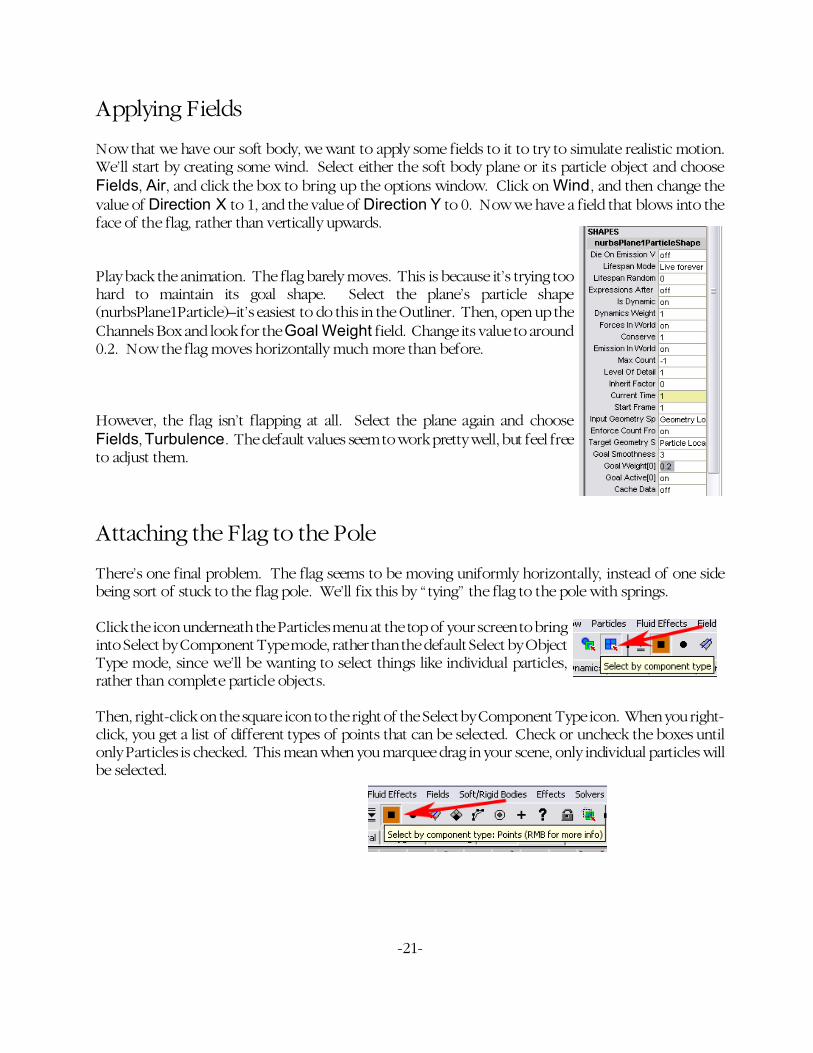
Click the icon underneath the Particles menu at the top of your screen to bringinto Select by Component Type mode, rather than the default Select by ObjectType mode, since we’ll be wanting to select things like individual particles,rather than complete particle objects.
Then, right-click on the square icon to the right of the Select by Component Type icon. When you right-click, you get a list of different types of points that can be selected. Check or uncheck the boxes untilonly Particles is checked. This mean when you marquee drag in your scene, only individual particles willbe selected.

-22-
Marquee drag around the upper corner of the flag, nearest to the pole, and the particles will turn blue,indicating that they are available to be selected. Marquee drag around the particle in the upper corner,and it will turn yellow, indicating that it is selected.
Right-click on the square icon again, and select NURBS CVs. Now, hold shift and marquee dragaround the very top of the flag pole, and all the CVs will turn purple, indicating that they can be selected.While still holding shfit, marqee drag around the top row of CVs, and they should turn yellow to showthat they are selected. The corner particle should still be yellow as well.
Now that the CVs and the particle are selected, we can make springs between them. Choose Soft/RigidBodies, Create Springs, and click the box to bring up the options window. Make sure that CreationMethod is set to All, and that Set Exclusive is checked. Set Exclusive means that springs will only becreated between points belonging to different objects, so we won’t get springs between CVs and otherCVs. Hit Create, and you should see some springs between the top of the pole and the corner of theflag.
Now we going to follow the same process for the bottom corner of the flag.Right-click on the square icon again and uncheck NURBS CVs, since we’llonly want to select particles again for the moment. Marquee drag twice aroundthe bottom corner particle until it turns yellow. Right-click the square iconagain and choose NURBS CVs once again. Making sure to hold shift,marquee drag once around part of the flag pole so that the CVs turn purple,then drag around the row of CVs nearest to the bottom corner of the flag.
Then, hold ctrl and select spring1 in the Outliner.Choose Soft/Rigid Bodies, Create Springs, andbring up the options window again. This time, put acheck next to Add to Existing Spring. This way,we’ll have just the one spring node for both sets ofsprings, so it’s easier to adjust settings.

-23-
Making Adjustments
Now we can get a little picky and try to make the animation a bit more realistic. First of all, lets makethose springs a little tighter. Select the spring node and open up the Channels Box. Increase the stiffnessto maybe 100, and the damping to around 0.5. Now the springs will have more of an influence on theflag.
Now, notice that the flag as a whole still moves horizontally by the same amount, no matter where alongthe flag you are. A more realistic motion would be that the parts of the flag farther away from the polewould be more affected by the wind than the parts closer to the pole. Select the Air field and move itaway from the pole, so that it’s about 3/4 of the way along the flag. Open up the Channels Box and lookfor the field that says Max Distance. Lower the value to 10, and also increase the Magnitude to 10.Now the outer part of the flag blows farther than the inner part.
At this point, the animation looks pretty good. You can tweak the Turbulence and Air field settings ifyou’d like to simulate other wind conditions. You can also add a gravity field if you feel like it looks toomuch like our flag is on the moon.


![Vaillant Technisch Bulletin 2010-03[rev4]:Vaillant Technisch Bulletin](https://img.pdfslide.net/doc/110x75/5875e7fe1a28abd4788bb4a0/vaillant-technisch-bulletin-2010-03rev4vaillant-technisch-bulletin-.jpg)