Embed Size (px)
Citation preview

TECHNO - ECONOMIC ANALYSIS OF CONNECTING COGENERATION
PLANT TO THE DISTRIBUTIVE NETWORK
Milan Ivanović*, Saša Minić*, Miloš Kostić**
University of Belgrade, Electrical Engineering Institute Nikola
Tesla, Koste Glavinića 8a, Belgrade*
MT-Komex doo, Ulica oslobođenja 22b, Beograd**
Abstract: The paper presents the results of techno - economic analysis of connecting cogeneration
plant to the distributive network of ED Belgrade. For all available cogeneration plant types,
criterion of permissible power has been checked, for connection to 35 kV and 10 kV bus, in nearby
TS 35/10 kV. The results of the analysis indicated the impossibility of connection CHP to the 10
kV. According to the criterion of permissible power, it was determined that the highest power of a
unit generator in a small power plant is 4.7 MVA, for connection to 35 kV bus in TS 35/10 kV. This
criterion was met for only six cogeneration units. For all of them, criteria of short-circuit power at
the connection point have been checked, as well as impact of their operation on network voltage.
Investments required for implementation of various solutions have been estimated. Only variable
costs, which are relevant for comparison of alternative solutions, have been taken into account.
Key words: small power plants, techno - economic analysis, CHP plant, distributed generation,
distributive network
TEHNO-EKONOMSKA ANALIZA PRIKLJUČENJA CHP POSTROJENJA
NA DISTRIBUTIVNU MREŽU
Milan Ivanović*, Saša Minić*, Miloš Kostić**
Univerzitet u Beogradu, Elektrotehnički institut Nikola Tesla, Koste Glavinića 8a, Beograd*
MT-Komex doo, Ulica oslobođenja 22b, Beograd**
Apstract: U radu su prikazani rezultati tehno - ekonomske analize priključenja postrojenja za
kogeneraciju na distributivnu mrežu ED Beograd. Raspoloživa postrojenja su podvrgnuta proveri
kriterijuma dozvoljene snage, pri čemu je razmatrana mogućnost priključenja na 35 kV i 10 kV

sabirnice obližnje TS 35/10 kV. Rezultati analiza su ukazali na nemogućnost priključenja na 10 kV
sabirnice. Prema kriterijumu dozvoljene snage, najveća vrednost jedinične snage generatora u maloj
elektrani iznosi 4.7 MVA, za priključenje na 35 kV sabirnice u TS 35/10 kV. Ovaj kriterijum je bio
zadovoljen za samo šest postrojenja. Za sve njih je proveren kriterijum snage kratkog spoja na
mestu priključenja i njihov uticaj na promene napona u mreži. Zatim su procenjene investicije
potrebne za realizaciju različitih varijantnih rešenja. U obzir su uzeti samo varijabilni troškovi, koji
su relevantni za poređenje varijantnih rešenja.
Ključne reči: male elektrane, tehno - ekonomska analiza, CHP postrojenje, distribuirana
proizvodnja, distributivna mreža
1. INTRODUCTION
This paper presents results of the study [1], whose main objectives were consideration of
connecting cogeneration plant to the distributive network of ED Belgrade and proposal of the most
cost - effective solution from the aspect of investments for connection to distributive network. The
idea of the investor, owner of the cardboard factory, was to replace existing steam boilers with
combined heat and power facility (CHP) and to produce electricity, according to feed-in tariffs [2].
Result of the study should be the solution that meets technical requirements [3], [4], and which has
lowest annual cost of the connection (which includes the annual cost of invested capital and annual
costs of losses).
Compliance with technical requirements for CHP are verified on the model of distributive
network for the area of ED Beograd, according to loading data from the first year of the study [5].
At the first, basic data about power supply of TS 35/10 kV Umka (near the cardboard factory) and
datasheets for all available CHP facilities are given, as an overview of the criteria for connecting
small power plants (SPP) to distributive network and parameters of the economic analysis of SPP
operation. Upper limit of power generator units has been determined for a variety of connection
points, according to technical requirements [3], which was preliminary selection of CHP facilities.
Selected facilities were subjects of further analysis.
2. DATA FOR THE STUDY
Data for the study [1] has been taken from the study [5], which was accepted at the EPS (Public
Enterprise Electric Power Industry of Serbia), 16 September 2010. in Belgrade. It was the main data
source for distributive network (110 kV and 35 kV), transformers 110/35 kV i TS 35/10 kV (rated

power, type, age and tap changer position), cables (type, length and operation state) and loads
modeled at X buss within TS 110/X kV and TS 35/X kV.
2.1. TS 35/10 kV Umka - Basic data
TS 35/10 kV Umka, located near the cardboard factory, dates from sixties of the last century. It is
powered from the 110/35 kV Belgrade 10, as shown in Figure 1. One line section is the overhead
line (AlFe 240 mm2, 110 kV, 13.74 km, operates under 35 kV) and the other, closer to closer TS
35/10 kV Umka, is cable (XHP Al 150 mm2, 35 kV, 1.43 km). TS 35/10 kV Umka can also be
powered from TS 110/35 kV Beograd 10 (by switching on 35 kV line TS 35/10 kV Barič - TS
35/10 kV Umka) or from TS 110/35 kV Beograd 2.
Figure 1: Basic and alternative power supply of TS 35/10 kV Umka
Busses of both voltage levels in TS 35/10 kV Umka are single busses with sectionalizer.
Facility 35 kV has six cells (two transformer cells, three distributive line cells and one empty cell).
At normal operationing conditions, 35 kV sectionalizer is closed. 10 kV buss is sectioned: each
section is powered from different transformer. Facility 10 kV has thirteen cells. Cardboard factory
switchyard is powered from the second transformer. Thear is no empty 10 kV cells in TS 35/10 kV
Umka, but equipment from measuring cell could be moved to the cell of the own consumption.
Another option is extension of the substation building, which could greatly affect costs and time.

Power supply of the cardboard factory is done by three feeders (XHE - 49A 3x(1x300 mm2));
one feeder is a backup. Reactive power compensation is performed at 0.4 kV buss in TS 10/0.4 kV,
with automatic adjustment of power factor. Therefore, voltage increase due to CHP connection will
not affect the production of reactive power.
2.2. Available CHP facilities - basic data
Data on available CHP plants, obtained from the client [11], are shown in table 1.
Table 1: Available CHP facilities - basic data B C D E F G H I J K L M N O P Q R S T U V W
Power (ISO conditions 15°C) (kW) 3 956 5 326 1 934 5 500 11 250 2 950 6 724 7 429 5 229 7 219 12 500 1 872 5 416 5 123 6 523 7 674 3 510 5 460 6 000 3 567 6 000 9 900Maximal power (-20°C) (kW) 4 585 6 300 2 000 13 840 8 002 8 500 6 253 8 472 15 000 1 872 5 400 7 600 8 830 4 300 6 581 7 200 4 300Number of units 2 1 4 1 2 1 1 1 1 1 4 1 1 1 2 1 1 2 1 1Total power (ISO) (kW) 7 912 5 326 7 736 10 000 5 900 6 724 7 429 5 229 7 219 10 000 7 488 5 123 6 523 7 674 7 020 5 460 6 000 7 134 6 000 9 900Efficiency of el. generation (%) 29.1 32.1 30.7 31.4 23.8 30.3 33.1 28.8 32.7 31.5 26.5 30.7 31.0 31.5 30.6 27.8 31.5 23.0 29.3 31.5 33.4Number of turbine axles 1 1 1 1 1 1 1 1 1 1 1 1 1 1 1 1 1 1 1 1 1Nominal turbine speed (rpm) 14 571 14 571 16 630 11 000 22 000 13 790 13 790 13 790 13 790 8 600 26 000 17 384 11 050 14 010 14 944 6 075 9 300 6 800Rated apparent power (kVA 4 700 2 400 14 065 3 300 7 595 9 000 6 600 9 000 12 500 2 250 4 375 6 750 4 375Generator voltage (kV) 11 11 11 11 11 6.6 11 11 10 10 11 0.4 11 11 11 11 11 11 11 11 11Nominal current (A) 738Frequency (Hz) 50 50 50 50 50 50 50 50 50 50 50 50 50 50 50 50 50 50 50 50 50Power factor 0.8 0.8 0.8 0.8 0.8 0.9 0.8 0.8 0,8-0,95 0,8-0,95 0,8-0,98 0.8 0.8 0.8 0.8 0.8 0.8Number of poles 4 4 4 4 4 4 4 4 4 4 4 4 4 4 4 4 4 4 4 4 4Number of phases 3 3 3 3 3 3 3 3 3 3 3 3 3 3 3 3 3 3 3 3 3Nominal generator speed (rpm) 1500 1500 1500 1500 1500 1500 1500 1500 1500 1500 1500 1500 1500 1500 1500 1500 1500 3000 1500 1500 1500
Varijant
3. TECHNO - ECONOMIC ASPECTS OF CONNECTING CHP PLANT TO THE
DISTRIBUTIVE NETWORK
3.1. Network model
Technical requirements for connecting CHP to distributive network have been checked on the
distributive network model [5]. TS 35/10 kV Umka is not covered with SCADA system. Maximal
loading of transformers and feeders is collected manually. Data for period 25.1.2005. - 17.12.2009.
were available. It should be noted that loading data had been collected only 34 times in this period
and that the period varies from three days to nine months.
Load of cardboard factory is modeled at 10 kV buss (section 2) in TS 35/10 kV Umka.
Maximal measured load of cardboard factory, which dates from February 2010, was 6.88 MW.
Reactive load has been calculated according to average power factor (0.974). Maximum of total
transformer loading for TS 35/10 kV Umka has been estimated according to measurements:
- Transformer T2 (section 1): P = 6.880 MW, Q = 1.614 Mvar, cos φ = 0.974
- Transformer T1 (section 2) : P = 3.512 MW, Q = 0.990 Mvar, cos φ = 0.970
3.2. Technical criteria for connecting small power plant to the distributive network
Basic technical requirements for connecting small power plants to the distributive network are
defined in [2], whose scope is connection of small power plants, capacity up to 10 MVA, to the
distributive network of rated voltage 0.4 - 35 kV. The basic technical criteria for connection small
generators to the distributive network are:

- permissible power of small power plant
- flickers
- current harmonics and
- short-circuit power.
Flicker requirements are important for wind generators and for solar power plants. Therefore,
this requirement is not considered. Requirements for harmonics could not be verified, because
necessary data were not available.
Synchronous impedance of the generator is necessary for verifying requirements for short-
circuit power. This requirement will be checked with the typical parameters of block-transformers.
Subtransient synchronous impedance of all generators (x"d) is determined according to [10].
3.2.1. Permissible power of small power plant
Requirement for permissible power of small power plant ensures that voltage variations at the point
of common coupling (PCC) will not exceed the value ∆um = 2%, during transients. According to
[3], SPP can be connected to distributive network if it meets following requirement:
50ks
NGMSS
k≤
⋅ (1)
where:
SNGM - the highest value of power generator unit in a SPP, or total power of generators if they are
simultaneously connected to the network, [MVA];
Sks - the actual value of the three-phase short-circuit power at the CCP, [MVA];
k = Ip/In - coefficient which is determined by the quotient of maximum starting current Ip and
generator rated current In; for synchronous generators, its value is 1.
All generators for available CHP (Table 1) are synchronous. Therefore, (1) can be simplified:
50ks
NGMSS ≤ (2)
3.2.2. Calculation of three-phase short-circuit power
CHP can be connected to distributive network if it meets requirement (2), i.e. if the highest value of
power generator unit (SNGM) is less then 2% of the actual value of the three-phase short-circuit
power at the CCP (Sks). Subtransient currents of three-phase short-circuit (I"k3) are taken from [7]:
- I"k3 = 6.0 kA for 110 kV buss at TS 110/35 kV Beograd 2
- I"k3 = 8.6 kA for 110 kV buss at TS 110/35 kV Beograd 10
Value of three-phase short-circuit power at 110 kV buss (Sk3M) is determined by using (3):
"3 3k M nM kS c U= 3I (3)
where:
c - voltage factor
UnM - nominal network phase-to-phase voltage
I"k3 - subtransient current of three-phase short-circuit
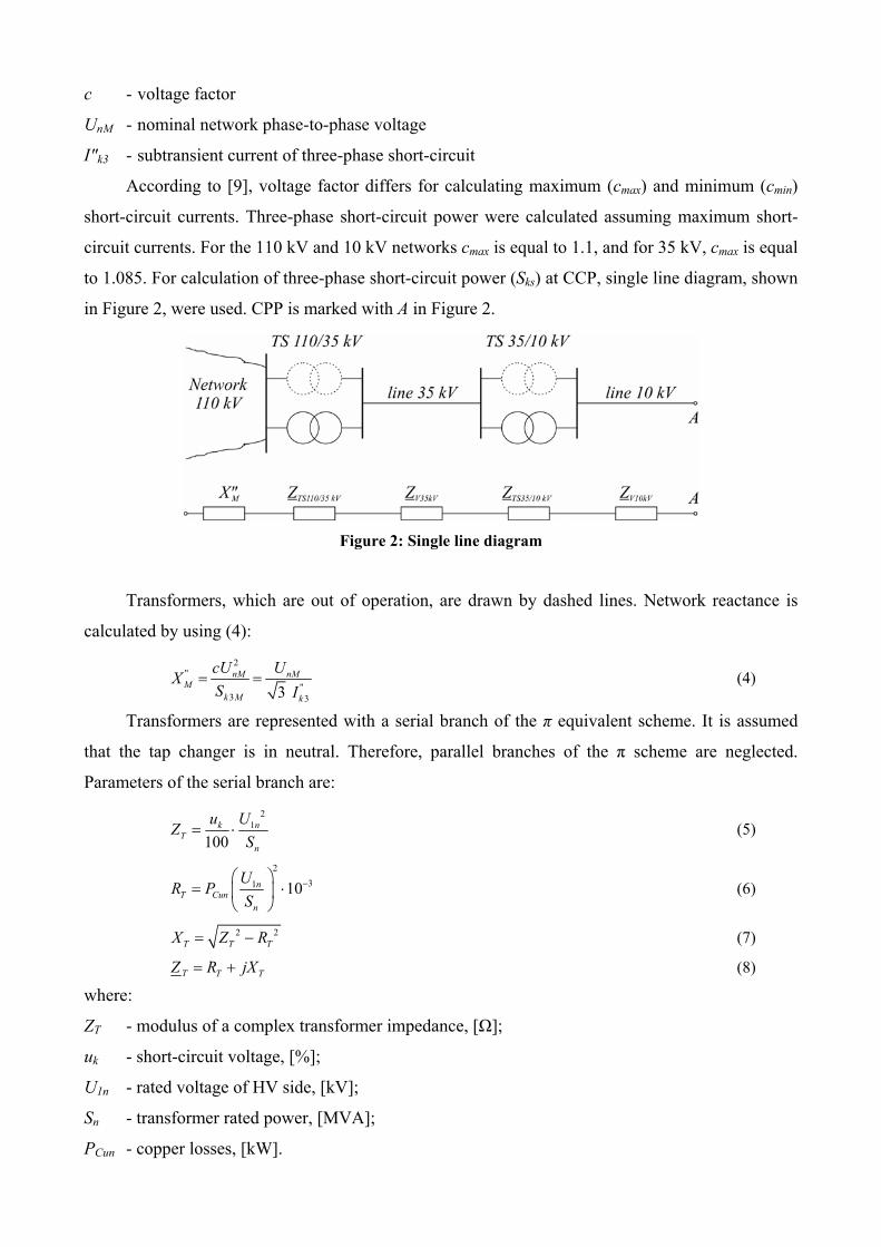
According to [9], voltage factor differs for calculating maximum (cmax) and minimum (cmin)
short-circuit currents. Three-phase short-circuit power were calculated assuming maximum short-
circuit currents. For the 110 kV and 10 kV networks cmax is equal to 1.1, and for 35 kV, cmax is equal
to 1.085. For calculation of three-phase short-circuit power (Sks) at CCP, single line diagram, shown
in Figure 2, were used. CPP is marked with A in Figure 2.
Figure 2: Single line diagram
Transformers, which are out of operation, are drawn by dashed lines. Network reactance is
calculated by using (4): 2
""
3 33nM nM
Mk M k
cU UXS I
= = (4)
Transformers are represented with a serial branch of the π equivalent scheme. It is assumed
that the tap changer is in neutral. Therefore, parallel branches of the π scheme are neglected.
Parameters of the serial branch are: 2
1
100k n
Tn
u UZS
= ⋅ (5)
231 10n
T Cunn
UR PS
−⎛ ⎞= ⎜ ⎟
⎝ ⎠⋅ (6)
2T T T
2X Z R= − (7)
T T TZ R jX= + (8)
where:
ZT - modulus of a complex transformer impedance, [Ω];
uk - short-circuit voltage, [%];
U1n - rated voltage of HV side, [kV];
Sn - transformer rated power, [MVA];
PCun - copper losses, [kW].

Lines are represented with a serial branch of the π equivalent scheme; parallel branches are
neglected. Parameters of the serial branch are:
V pod VR r l= (9)
V pod VX x l= (10)
V V VZ R jX= + (11)
where:
rpod - line resistance, per unit length, [Ω/km];
xpod - line reactance, per unit length, [Ω/km];
lV - line length, [km].
For calculation of short-circuit currents in systems with different voltage levels, it is necessary to
transfer impedance values from one voltage level to another, usually to that voltage level at which
the short-circuit current is to be calculated or to transform them to per unit system. Voltage of
equivalent voltage source at the short circuit (as shown in Figure 3) is calculated by (12):
T nAE c U= (12)
where:
c - voltage factor;
UnA - nominal voltage of point A, [kV].
Finally, three-phase short-circuit power at CCP (point A) is calculated: 2
T nA nAks
ek ek
E U c USZ Z
= = (13)
where
"110/ 35 35 35/10 10ek TS kV V kV TS kV V kVMZ jX Z Z Z Z= + + + + (14)
Figure 3: Single line diagram for calculation of three-phase short-circuit power
It should be noted that in the calculation of the three-phase short-circuit power for network elements
selection, the active resistance is neglected. If the same principle is applied to this case (does SPP
meet requirements for connecting to distributive network), calculated short-circuit power at the
CCP would be larger than the real one, which could affect condition (1). Therefore, it is necessary
to consider resistance.

It is necessary to consider the most critical case from the aspect of the criterion (1). Figure 2
shows two TS (with two transformer units per TS; two transformers, which are out of operation, are
drawn with dashed line). Failure of the transformer or its planed disconnection reduces three-phase
short-circuit power at CCP (point A). If generator is connected to a weakened network, voltage
variations could exceed allowed value (∆um = 2%). Therefore, three-phase short-circuit power is
calculated for the weakened network, i.e. network without (parallel) transformers with the lowest
impedance.
3.2.2. Checking short-circuit power criterion
After connecting SPP, short-circuit power at CCP is increased. It is necessary to calculate increased
short-circuit power and to check if it affects any network element. Single line diagram, shown in
Figure 4, is used for calculation.
Figure 4: Single line diagram for calculation of increased three-phase short-circuit power
In Figure 4, following symbols are used:
A - common coupling point;
ZPV35kV - impedance of 35 kV connection line;
ZBT - impedance of the block-transformer;
X"d - generator's subtransient reactance;
Zek - short-circuit impedance, before connecting SPP.
It is necessary to transfer all impedances from one voltage level to another, usually to voltage level
at which the short-circuit current is to be calculated. If any network element is affected with
increased short-circuit power:
- short circuit current should be limited,
- affected element should be replaced,
- common coupling point should be relocated ,
- connection line parameters should be changed, etc.

3.3. Impact of SPP operation on distributive network
Technical criteria for SPP operation in parallel with network should be checked. SPP are often far
away from areas with high loads. In most cases, total power of SPP is much greater then
consumption supplied from the TS 35/10 kV, at which SPP is connected. Therefore, direction of
power flow in supplying 35 kV line is changed. In addition, injection of active and reactive power
increases the voltage in a part of the network close to CCP. From the aspect of the voltage increase,
the most critical case is the maximum generation of SPP in parallel with low loaded network. The
minimum voltages occur during peak demand when SPP is disconnected. In both cases, the network
voltages must be within the limits shown in Table 2 [4].
Table 2: Voltage limits
Nominal voltage Minimal voltage in normal operation
Minimal post-accidental voltage
Maximal voltage in normal operation
110 kV 99 kV 99 kV 121 kV 35 kV 31.5 kV 31.5 kV 38 kV 20 kV 19 kV 18 kV 21.4 kV 10 kV 9.5 kV 9 kV 10.7 kV
In order to achieve that voltages at 10 kV bus of all TS 10/0.4 kV (supplied from considered
TS 35/10 kV) get close to the nominal voltage, at the maximum load of the network, with SPP
disconnected, it is necessary to adjust the transmission ratio in TS 35/10 kV. For the analysis of the
maximum generation of SPP (rated power, cos φ = 0.95) at minimum load network, network
models involve generating (PV) node and block-transformer. According to [4], maximum allowed
voltage variation in the steady state at CCP is ∆Um = ± 5%. If the voltage variation exceeds
specified value, technical requirement for operation of SPP in parallel with distribution network is
not met.
3.4. Parameters of economic analysis of SPP operation
Connection of CHP to distributive network is evaluated by economic criteria, in addition to
technical criteria. The annual cost of each variants of CHP connection has two components: the
costs of losses and the investments cost of the connection. Detailed explanation is given in [5].
Interest of the SPP owner is to transfer energy from the SPP to CCP with minimal losses.
Reduction of losses implies increase of the cross section (of the connection line) or connection at a
higher-voltage level, but both require additional investments. It is necessary to evaluate investments
and losses in connection line. Costs of losses CHP are calculated by using (15):
γτ PCC EP ⋅⋅= (15)
where
CE - price of the electric energy produced in SPP;

τ - equivalent duration of maximal losses in connection line;
Pγ - maximal power loss.
Actual feed-in tariffs for CHP facilities for fossil fuels [2] are shown in Table 3.
Table 3: Feed-in tariffs for CHP facilities Rated power Feed-in tariff
(MW) (c€/kWh)- 0.2 10.40
0.2 - 2 10.667 - 1.333 P2 - 10 8.20
Equivalent duration of maximal losses (τ) represents the ratio of energy loss and maximal
power loss (for elements with similar annual load duration curves):
2
0.17 0.83 8760TTτ = ⋅ + ⋅ (16)
where T is equivalent duration of maximal loading of particular network element. For the
connection line, it represents the ratio of maximal (power) loading and total annual energy from the
SPP. Equivalent duration of maximal loading for the cardboard factory is equal to 6 955 h.
According to (16), equivalent duration of maximal losses is equal to 5 765 h. For assumed purchase
price of 8.2 c€/kWh, calculated (15) price of the power losses in the connecting line is 473 €/kW.
Unit prices of basic network elements are taken from the study [12].
4. CRITERIA FOR CONNECTING CHP TO DISTRIBUTIVE NETWORK OF ED
BEOGRAD
4.1. Introduction
Review of technical requirements for connection SPP is given in section 3.2. From the aspect of
connecting CHP to distributive network, criterion of permissible power is the most rigid (Section
3.2.1). Criterion of short-circuit power (Section 3.2.2) is used for the calculation of short-circuit
power at the CCP and checking the adequacy of existing network elements to the new conditions in
the network. Finally, it is necessary to consider the impact of SPP operation on distributive network.
4.2. Permissible power of CHP
According to criterion of permissible power, if TS 35/10 kV Umka is supplied from TS
110/35 kV Beograd 10, the highest value of power generator unit in a CHP are 2.115 MVA (10 kV
buss at TS 35/10 kV Umka, section 1) and 4.737 MVA (35 kV buss at TS 35/10 kV Umka).

None of available CHP facilities meet criterion of permissible power for connecting to the first
section of 10 kV buss at TS 35/10 kV Umka. For connection to 35 kV buss at TS 35/10 kV Umka,
the same criterion is met for only six variants: B, D, G, M, R and U, as shown in Table 4.
Table 4: Data for preliminary selected CHP facilities
B D G M R U
Manufacturer Centrax UK - Rolls Royce Dresser Rand IES Canada OPRA Turbine Turbomach -
SolarVericor Power System - MTU
Model CX 501 KB5 KG2 IES 3000B OP16 Centaur 40 VPS4Power (ISO conditions 15°C) (kW) 3956 1 934 2 950 1 872 3 510 3 567Maximal power (-20°C) (kW) 4585 2 000 1 872 4 300 4 300Number of units 2 4 2 4 2 2Total power (ISO) (kW) 7912 7 736 5 900 7 488 7 020 7 134Efficiency of el. generation (%) 0.291 23.8% 26.5% 27.8% 29.3%Number of turbine axles 1 1 1 1 1 1Nominal turbine speed (rpm) 14571 22 000 26 000Rated apparent power (kVA) 4700 2 400 3 300 2 250 4 375 4 375Generator voltage (kV) 11 11 6.6 0.4 11 11Nominal current (A)Frequency (Hz) 50 50 50 50 50 50Power factor 0.8 0.8 0.9 0.8 0.8 0.8Number of poles 4 4 4 4 4 4Number of phases 3 3 3 3 3 3Nominal generator speed (rpm) 1500 1500 1500 1500 1500 1500
Varijant
Nominal voltages of all generators from the Table 4 (X = 0.4 kV, 6.6 kV and 11 kV) differs from
the nominal voltage of common coupling point (35 kV). Therefore, step-up transformers (X/35 kV)
are needed. Number and rated power of transformers will be determined in further analyzes. Short-
circuit power criterion will be checked for each CHP facility. According to [3] and [4], total power
of all generators in SPP can not exceed 10 MVA. Estimated length of 35 kV connection line is
0.3 km.
According to costs, given in section 3.4, and prices of basic network elements [12], it was
determined that 35 kV cable XHE 49A, 185 mm2 is the most economical for the powers within
range [2.7 MW - 10 MW]. In the next Section, detailed analysis of the connection of a single CHP
plant from the Table 4 is given. Summary results of the analysis are given in Section 4.4.
4.3. Varijant B: Centrax UK - Rolls Royce, model CX501 KB5
CX501 KB5 has two generators (11 kV, 4.7 MVA). The proposed connection scheme is shown in
Figure 5.
The ratio of the block transformers (BT1 and BT2) should be 11/35 kV, and their nominal
power should be 6.3 MVA. For this purpose, standard transformer (35/10.5 kV) can be used, but tap
changer should be adjusted to 33.25/10.5 kV. Switchyard for 35 kV should have two transformer
cells and a cell for the 35 kV cable line (connection to TS 35/10 kV Umka), as shown in Figure 5. It
is assumed that the own consumption will be supplied from the generator buss.

Figure 5: Single line diagram
4.3.1. Checking criterion of short-circuit power
Calculated value of three-phase short-circuit power for 35 kV buss at TS 35/10 kV Umka is SKS,M =
236.85 MVA. After connecting CHP plant (Figure 5), three-phase short-circuit power is increased
to 291.6 MVA. Maximal three-phase short-circuit power for 35 kV network is 750 MVA, which
means that variant B meets criterion of short-circuit power.
4.3.2. Impact of CHP operation on distributive network
Impact of CHP operation on distributive network is analyzed through variation of network loading
and CHP generation (for cos φ = 0.95), as shown in Table 5.
Table 5: Steady state voltage variations at common coupling point
Voltage at common coupling point Maximum load
Minimum load
Maximum generation of CHP 33.76 kV 36.15 kV CHP at idle 33.65 kV 35.93 kV
Results shown in Table 5 show that (steady state) voltage variation is ∆Um = 0.11 kV for
maximal load, ∆Um = 0.22 kV for minimal network load. Voltage variation at CCP is 2.5 kV during
the year. Calculated voltages are within voltage limits, given in Table 2.
Results given in Table 5 are calculated for the expected range of voltage variations at 35 kV
buss (in TS 110/35 kV Belgrade 10), the expected range of load changes in the analyzed part of the
distribution network during the year and minimal and maximal CHP generation. It is assumed that
the voltage at 35 kV buss in TS 110/35 kV Belgrade 10 (referent voltage 35 kV) will be higher then
34 kV for maximal load, and lower then 36 kV for minimal load. Under these conditions, steady
state voltage variations for both sections of 10 kV buss in TS 35/10 kV Umka (section 1: 9.81 kV -
10.41 kV: section 2: 9.73 kV - 10.51 kV), which are within voltage limits, given in Table 2.

4.4. Summary results of the analysis
Table 6: Proposed variants - technical details
Varijant Manufacturer Model SnG (MVA) cos φ UnG
(kV) SnBT
(MVA) Connection line,
35 kV SKS, PAR (MVA)
UP,min (kV)
UP,max (kV)
B Centrax UK - Rolls Royce CX 501 KB5 2 x 4.7 0.8 11 2 x 6.3 XPE 49-A 185 mm2 291.6 33.65 36.15
D Dresser Rand KG2 4 x 2.4 0.8 11 4 x 2.5 XPE 49-A 185 mm2 289.9 33.65 36.13
G IES Canada IES 3000B 2 x 3.3 0.9 6.6 2 x 4 XPE 49-A 185 mm2 284.4 33.53 35.94
M OPRA Turbine OP16 4 x 2.25 0.8 0.4 4 x 2.5 XPE 49-A 185 mm2 300.9 33.65 36.11
R Turbomach - Solar Centaur 40 2 x 4.375 0.8 11 2 x 6.3 XPE 49-A 185 mm2 288.7 33.65 35.81
U Vericor Power System - MTU VPS4 2 x 4.375 0.8 11 2 x 6.3 XPE 49-A 185 mm2 288.7 33.65 36.08
Legend: SnG rated power cos φ rated power factor UnG rated generator voltage SnBT total of transformer rated power (X/35 kV) SKS, PAR three-phase short-circuit power for 35 kV buss (TS 35/10 kV) Umka after connecting CHP SNGM highest value of power generator unit UMP, min minimal expected voltage at CCP, for maximal load and CHP at idle, 34 kV at 35 kV
buss in TS 110/35 kV Beograd 10 UMP, max maximal expected voltage at CPP, for minimal load and maximal generation of CHP
(cos φ = 0.95), 36 kV at 35 kV buss in TS 110/35 kV Beograd 10
Table 7: Proposed variants - investments for CHP connection to 35 kV buss in TS 35/10 kV Umka
Varijant Manufacturer Model SnBT (MVA) N35 kV NX kV SK
(mm2) CBT
(1 000 €) CC35kV
(1 000 €) CCX kV
(1 000 €) CK
(1 000 €) CUK
(1 000 €)
B Centrax UK - Rolls Royce CX 501 KB5 2 x 6.3 3 2 185 146 87 40 17.55 290.55
D Dresser Rand KG2 4 x 2.5 5 4 185 144 145 80 17.55 386.55
G IES Canada IES 3000B 2 x 4 3 2 185 108 87 40 17.55 252.55
M OPRA Turbine OP16 4 x 2.5 5 4 185 144 145 80 17.55 386.55
R Turbomach - Solar Centaur 40 2 x 6.3 3 2 185 146 87 40 17.55 290.55
U Vericor Power System - MTU VPS4 2 x 6.3 3 2 185 146 87 40 17.55 290.55
Legend: SnBT total of transformer rated power (X/35 kV) N35 kV number of 35 kV cells NX kV number of X kV cells, where X is rated generator voltage (or higher) SK cross section of XHE 49-A cable, for 35 kV CBT total price of transformers X/35 kV C35 kV total price of 35 kV cells CX kV total price of X kV cells (it is assumed that the prices od X kV and 10 kV cells are equal)

CK price of XHE 49-A cable (35 kV, 0.3 km), including costs of cabling CUK total of considered variable costs
Tabela 8: Proposed variants - investments for CHP connection to 35 kV buss in TS 35/10 kV Umka
Varijant Manufacturer Model PnG (MW)
iBT ( % )
IPV ( % )
PgBT (kW)
PgPV (kW)
PgUK (kW)
pgUK ( % )
Egod (MWh)
CE (1 000 €) cB
B Centrax UK - Rolls Royce CX 501 KB5 7.912 64 37 38 3 41 0.52 62 968 5 113.0 17.6
D Dresser Rand KG2 7.736 79 36 52 3 55 0.71 61 448 4 989.6 12.9
G IES Canada IES 3000B 5.900 78 28 36 2 38 0.64 46 896 3 808.0 15.1
M OPRA Turbine OP16 7.488 73 35 44 3 47 0.63 59 528 4 833.7 12.5
R Turbomach - Solar Centaur 40 7.020 57 33 30 3 33 0.47 55 896 4 538.8 15.6
U Vericor Power System - MTU VPS4 7.134 58 33 30 3 33 0.46 56 808 4 612.8 15.9
Legend: PnG total of generator rated power iBT loading of transformer X/35 kV iPV loading of 35 kV connection line PgBT power loss in transformer X/35 kV PgVD power loss in 35 kV connection line PgUK total power loss pgUK ratio of the power loss and total of generator rated power Egod annually generated energy (for 8 000 h/years) CE price of annually generated energy (8.75 c€ / kWh) cB ratio of price of annually generated energy and total of considered variable costs
5. CONCLUSIONS
This paper presents results of techno - economic analysis of connecting CHP to the distributive
network. At the first, brief description of technical requirements is given, as well as parameters of
economic analysis of CHP operation. Technical requirements do not define operational parameters
of small power plants. A brief description of additional criterion, which considers impact of SPP
operation on distributive network, is also presented.
The most economical 35 kV cable type for connection CHP has been selected according to
cost/benefit analysis. All available CHP plants were subject to verification of permissible power
criterion. Analysis results indicated that none of available CHP plants do not meet technical
requirements for connection to the 10 kV bus in TS 35/10 kV Umka. Upper limit of power
generator units has been determined for connecting CHP to 35 kV buss in TS 35/10 kV Umka,
according to permissible power criterion, which was preliminary selection of CHP facilities.
Selected facilities were subjects of further analysis.

For all selected facilities short-circuit power criterion has been checked. Impact of CHP
operation on distributive network (additional criterion) was also analyzed. At the end, summary
results of the techno - economic analysis is given, which were guidelines for the final selection of
CHP facility.
This paper is based on the research results of the project "Intelligent power networks", which
is financed by the Ministry of Education, Science and Technological Development.
REFERENCES
[1] Analiza postojećeg stanja u TS 35/10 kV Umka i mogućnost priključenja CHP postrojenja na
lokaciji fabrike kartona Umka, Elektrotehnički institut Nikola Tesla, 2010.
[2] Uredba o merama podsticaja za proizvodnju električne energije korišćenjem obnovljivih izvora
energije i kombinovanom proizvodnjom električne i toplotne energije, Službeni glasnik RS br.
99/2009 do 1.12.2009. godine.
[3] Zbirka tehničkih preporuka Direkcije za distribuciju EPS-a, 2001
[4] Pravila o radu distributivnog sistema (verzija 1.0), 2009, JP EPS
[5] Plan dugoročnog razvoja elektrodistributivne mreže EPS PD "Elektrodistribucija Beograd" na
konzumnom području do 2025. godine-II faza, Elektrotehnički institut Nikola Tesla, 2009.
[6] Studija perspektivnog razvoja prenosne mreže Srbije do 2020 (2025) godine, Elektrotehnički
institut Nikola Tesla, 2007.
[7] Plan razvoja prenosnog sistema za period do 2014. godine, EMS, 2009.
[8] Miladin Tanasković, Tomislav Bojković, Dragoslav Perić, Distribucija električne energije,
Akademska misao, Beograd, 2007
[9] Milan S. Ćalović, Andrija T. Sarić, Osnovi analize elektroenergetskih mreža i sistema,
Akademska misao, Beograd, 2004
[10] Richard Roeper, Short-circuit Currents in Three-phase Systems, Siemens Aktiengesellschaft,
John Wiley & Sons, Berlin and Munich, 1985,
[11] Studija ekonomske opravdanosti izgradnje kogenerativnog postrojenja u fabrici kartona Umka,
MT-Komex doo, Beograd, 2010.
[12] Studija perspektivnog dugoročnog razvoja električne mreže naponskog nivoa 10 kV na
području ogranka Pirot, Elektrotehnički institut Nikola Tesla, 2009.