Embed Size (px)
Citation preview

The combination of a new grinding tool material (CBN).new applied grinding technology, and new bevel gear grind-ing machines has made it possible to drastically reduce thegrinding time and cost, while at the same time improvingquality and consistency, making bevel gear grinding techni-cally andeconomically feasible for mass production. (18)
Technological Fundamentals ,ofCBN Bevel Gear Finish Grinding
byHarvey Dodd & D. V. Kumar
The Gl.eason WorksRochester, NY
INTRODUCTIONThe bevel gear grinding process, with conventional wheels,
has been limited to applications where the highest level ofquality is required. Grinding with conventional wheels hasnot been used in high production applications, because ofthe long cycle times and resultant high manufacturing costs.A further hindrance to the wider application of bevel geargrinding has been the lack of an understanding of the fun-damental. principles involved in the process. Rather than bas-ing i.t on applied engineering knowledge, gear grinding suc-cess has been dependent upon the experience of skilled grind-ing machine operators ..This can make it difficult to get con-sistent results from day to day.
Dr. Kegg(l) has noted that the industry trend is towardhigher part quality, indicating increased use of grinding, butwith a diminishing supply of skilled machine operators.
In addition to these diverging tendencies, a new grindingwheel abrasive (CBN) has been introduced. Much informa-tion has been published highlighting the benefits of CBNgrinding, such as reduced grinding time and overall costs,maintaining consistent geometrical tolerances and improvedmetallurgical. integrity. Despite these promised results, CBNgrinding has been slow to be implemented in high volumeproduction applications because the additional technologyalso has not been well understood by many potential users.
During the past few years a significant amount of fun-damental grinding research has been conducted by severalresearchers (2-17). Thisartide will show how the fundamen-tal research has been applied to CBN bevel gear grinding.The understanding and implementation of applied grindingtechnology has made it possible to change the grindingmachine from the mysterious black box. of the past to asystem having predictable and consistently repeatable results.
fUNDAMENTALS OF CBN GlUNDINGOF HARDENED MATERIALS
CBN Physical PropetiesElevated Temperature Hardness
Fig. 1 shows the elevated temperature hardness of the fourmajor abrasives'P'.
The temperatures encountered by the cutting points of theabrasive grains are well above room temperature, thus theelevated temperature properties are of greater significancethan the room temperature properties. It can be seen that thehardness of diamond decreases at a much faster rate than theother three abrasives with increasing temperature. In add:i-tion, diamond wears rapidly by graphitization or oxidationin the presence of iron at high temperatures and is, therefore,not usually successful in grinding ferrous materials. CBN onthe other hand maintains its hardness advantage over siliconcarbide and aluminum oxide at all temperatures up to 1830 of(lOOOoC) and is chemically inert in the grinding of ferrousmaterials.
Grain Shape and Its Influence on. the Rateof Wear flat Development
Attritious wear, the slow gradual. development of a. wear
AUTHORS:
MR. HARRY D. DODD received his Bachelor and Masters ofScience degrees in Mechanical Engineering {rom the Rocheste« Instituteof Technology. In 1972 he joined The Gleason Works and has workedin both the Machine Design and the Research and Developmentdepartments. Since 1978 his research work has bee-n involved withthe use of 5uperabr:asives in the deoelopmen: of high ~fficiency grind-ingprocesses. Currently he isa Research Staff Engineer responsiblefor ,the Grinding Process Research Group. He is a member of the
.30' Gear Technology
ASME, SME, and the AES. and is a certified abrasive engineer inthe field of superabrasines. He is also a member of the editorial ad-visory board of the Creep Feed NewsleHer.
MR. K. V. KUMAR is Research Project Engineer at The GleasonWorks. and is actively involved in hard finishing process ,develop-ment for bevel gears_ He received his MS from Carnegie Mell'onUniversity and PhD from An'zona State University .in MechanicalEngineering. He is an ,associate member of ASME .

Fig. 1- Micro-Hardness of CBN in terms of thetemperat ure in comparison10 other abrasive grains,lul
flat, limits the useful operation of a grinding wheel duringfinish grinding.
fig .. 2 shows photographs of an aluminum oxide and aCBN crystal. The CBN crystal has a.well-defined structure,while the aluminum oxide grain does not. Aluminum oxidecrystals on the average have a spherical form(19) while theCBN crystals have a block form shown in F.ig. 2. It can beseen that for a given amount of crystal wear the length ofthe wear flat will be signi.ficantly greater for the aluminumoxide. A comparison of wear flat areas shows an even greaterdifference.
The size of the wear flat area has a direct effect on burn-ing. Malkin(ZOlhas shown that when a wear flat area of 4%of the wheel surface has developed, burning is encounteredwith conventional wheels. The cubic structure of CBN willallow for greater radial wear before the same size wear Aatis developed.
Anisotropic Crystal Stren,gthlike diamond, CBN has anisotropic strength properties.
This can result in a self-sharpeningacti.on under certain
ALUMINUM OXIDE GRAIN
~00'" Wear
TFig. 2-Effect ,of Grain. Shape on the Rate of Wear Flat Development.
November IDec&mber 1985 3: l'
2000
"f::;~ 1600
f;:;~."c 12000U;;;Eiiis:.. 800
400
AlUtll!il!lMJl!l! IIUCQN 'ITIII. cono C8!O -0_ c_.r.•, • 2!1 .., 50 ""'l 1300 """iIT\JI/l .• J~' 111,61 flUl (80; 1M OJ """" (l2Ol
Fig. 3-Comparison of Thermal Conductivity at Room Temperature.
conditions, (14) providing a new sharp cutting edge withoutcrystal pullout.
Thermal! ConductivityFig. 3 shows the thermal conductivity of the four major
abrasives, and of steel and copper. (21.22) The significance ofthis property will be shown in the next section on thermalinput to the workpiece.
Grinding Characteristics ofCON vs. Conventional Abrasives
Low Thermal Input WithIncreased Force and Power Reqmrement
In CBN grinding the forces and power aee higher than withconventional wheels .. CBN grinding machines thus requiregreater spindle stiffness and power. Salje(2) has shown thatat the same metal removal rate a CBN wheel required 1.25to 2.6 times the power of an aluminum oxide wheel. Thishas been rather puzzling since CBN is a harder and sharperabrasive. The reason for this difference in power requirementbetween the two abrasives can be explained by a simpleanalysis of the heat flow between wheel and work in the twocases.
Fig. 4 is a schematic of the surface grinding operation. Itis assumed for simplicity that all of the power consumed ingrinding is dissipated as heat between wheel and work only.
q = qg + qw
where q = total heat flux in grindingqg= heat flux to wheelqw = heat flux to work
Denoting ks' and kw as the thermal conductivities for
3;2 Gear Technology
wheel and work, A as the wheel-work contact area and tSItwas thicknesses for wheel and work across which there isan equal temperature drop, then
(2)
The quantity within each bracket is the thermal resistanceof wheel and work respectively. Since the thickness layer fromthe point of view of thermal damage to work and wheel. isof similar magnitude, equation(Zl can be simplified as
(3)
From equations (1) and (3)
q1 + (kslkw)
Using the room temperature thermal conductivity valuesfrom Fig. 4, in the above relationships, for the case of analuminum oxide wheel it is seen that 63 % of the total heatgenerated goes into the work and 37% into the wheel .. In thecase of a CBN wheel it is seen that only 4% of the total heatgenerated goes into the work while 96% ends up in the wheelIn actual practice, thermal conductivity varies withtemperature for both the abrasive and the work material,Nevertheless the amount of heat input to the work will bemuch less wi.th CBN than with conventional. abrasives.Therefore, chips are formed at a lower temperature withCBN. Since the forces required to work a material at lowertemperatures are higher, CBN grinding is accompanied byhigher forces and power requirements.
It should not be misconstrued from the above analysis thatthermal damage to work is not possible with CBN wheels.Thermal damage can be produced with CBN, but when the
Total HealGenerated Q
--_v
Fig. oj - Heat Distribution between wheel and worm In surface grinding

wheel. is properly prepared this win happen at a much highermetal removal rate and grinding spindle power as comparedto conventional wheels. On the other hand, the high heatinput to the CBN wheel requires proper coolant applicationto increase the longevity of the wheel.
As a result of the [ower heat input to the workpiece withCBN grinding wheels and a reduction in the tendency to bum,CBN wheels are normally used at higher metal removal ratesthan conventional wheels, This further increases the grindingForces and power. Thus, it is not unusual for the forcesen-countered in CBN grinding to be 4. to 10 times greater thanwith an aluminum oxide wheel.
Residual str'esses and fatigu.e strengthThe functional behavior of a ground component is substan-
tially determined by the material physical properties, as wellas, the residual stresses near the surface,m,l31 Residualstresses will have an eHect on both the static strength andthe dynamic strength (fatigue strength).
The initiation and growth of cracks can be accelerated orretarded by residual stresses. Tensile residual stresses will in-crease the possibility of crack initiationa:nd growth, whilecompressive stresses will retard them.
The near surface residual stresses as a result of grindingcan be produced by one or a combination of the followingmeans:
thermat heat gen.er:atoo during grinding;rnechanicali plastic deformation;chemical: reactions with machining fluids and absorption
of elements in the machined su.rface.(24)Thermally induced residual stresses are tensile. The highly
localized temperatures at the surface cause the work materialto yield in compression as shown in Fig. s. After the heatsource has passed and the material cools, the plastically com-pressed surface material. is left in tension. Snoeys(25) hasfound that increased maximum grinding temperatures causehigher peak residual. 'tensile stresses. Bellows(U) has found
~)~f/y/
,Surface ILayer
Pig'.S-Mechanism for Thermal-Plastic Induced Residual Stresses
175 ,oonl!don<;e IlINl I
Fig. 6
that less abusive grinding conditions decrease the tensileresidual. stresses,
The effect of various levels of thermal input on the fatiguelife of bearing rings has recently been investigated.(l3) In fig.6 it can be seen that the 1..10fatigue life decreased dramaticallywith an increase in U IU· (the ratio of the measured specificenergy to the specific energy at burning). This ratio is direct-ly proportional to the grinding power and the grindingtemperature; and points. out that higher thermal input to thework surface will greatly reduce the fatigue lUe.
Men the grinding temperature is sufficie.ntly low, residualstresses are 'caused primarily by plastic deformation. Thismechanical cold working of the surface material results incompressive residual stresses in a manner similar to,shot peen-ing. Also, at lower temperatures chemical reactions are less,likely, or at [east will often proceed ata slower rate.
Many investigators have compared the residual. stressesproduced by CBN andconventional wheels and have shownthat CBN wheels tend to produce compressive residualstresses while aluminum oxide wheels tend to produce ten-sile residual stresses.(4.S,lJ.IS.27.28.29lThis differ,ence can be ex-plained by the previously discussed differences in thermalconductivity of the two abrasives. This proposition is tu:r~ther supported by the grinding tests of Ratterman(Sl in whichthe residual stresses produced by CBN, diamond, and con-ventional wheels were compared. The test results showed thatdiamond wheel grinding produced residual. compressivestresses which were larger (more compressive) than tha't from
November/December1985 33,
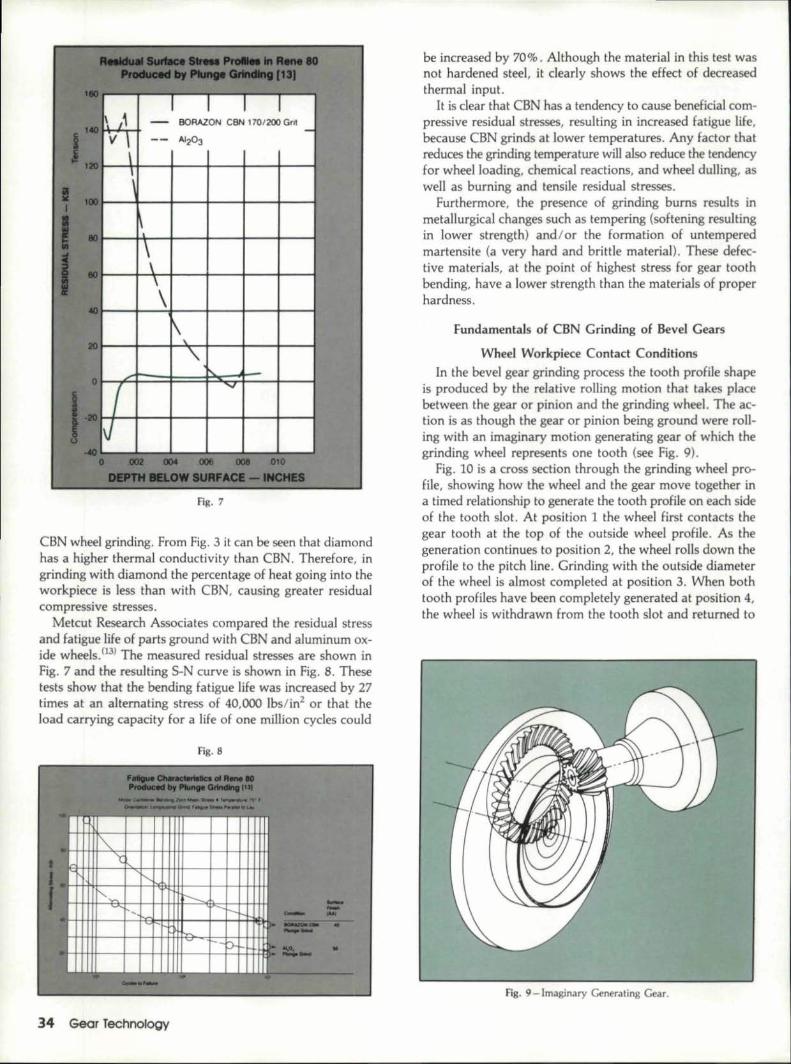
Fig. 'J
CBN wheel grinding. From Fig. 3 it can be seen that diamondhas a higher thermal conductivity tha:n CBN. Therefore, ingrinding with diamond the percentage of heat going into theworkpiece is less than with CBN, causing greater residual'compressive stresses.
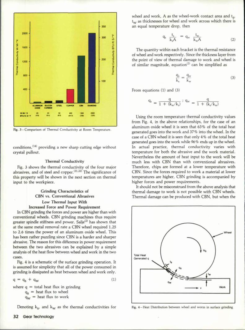
Metcut Research Associates compared the residual stressand fatigue life of parts ground with CBN and aluminum ox-ide wheels. (IJ) The measured residual stresses are shown inFig. 7 and the resulting S-N curve is shown in Fig.S. Thesetests show that the bending fatigue life was increased by 27times at an alternating stress of 40,000 Ibs/in2 or that theload carrying capacity for a life of one million cycles could
Fig, 8
,c. ~-~~.~"...... I
~, ......"-I
..:... "---......
'i&. , '"I 'c~\ I",;;; I'- I
'- '-".... I--- -~.~
~I --r- -- - ....
~' II"I'"'=:- •;ki "'"'~ r-- :).-~ ~ ..- •~.~~ I I
,'. '~~_;;i:! ~
34 Gear Technology
be increased by 70% '.Although the material in this test wasnot hardened steel, it dearly shows the effect of decreasedthermal input,
It is dear that CBN has a tendency to cause beneficial. com-pressive residual stresses, resulting in increased fatigue life,because CBN grinds at lower temperatures, Any factor thatreduces the grinding temperature will also reduce the tendencyfor wheel loading, chemical reactions, and wheel dulling, aswell as burning and tensile residual stresses.
Furthermore, the presence of grinding bums results inmetallurgical changes such as tempering (softening resuhingin lower strength) and/or the formation of untemperedmartensite (a very hard and brittle material). These defec-tive materials, at the point of highest stress for gear toothbending, have a lower strength than the materials of properhardness .
.Fundamentals of CBN Grinding of Bevel Gears
Wheel Workpiece Contact ConditionsIn the bevel gear grinding process the tooth profile shape
is produced by the relative rolling motion that takes placebetween the gear or pinion and the grinding wheel. The ac-tion is as though the gear or pinion being ground were roll-ing w:ith an imaginary motion generating gear of which thegrinding wheel represents one tooth (see Fig. 9).
Fig. 10 is a cross section through the grinding wheel pro-file, showing how the wheeland the gear move together ina timed relationship to generate the tooth profile on each sideof the tooth slot. At position 1 the wheel first contacts thegear tooth at the top of the outside wheel profile. As thegeneration continues to position 2, the wheel rolls down theprofile to the pitch line. Grinding with the outside diameterof the wheel is almost completed at position 3. When bothtooth profiles have been completely generated at position 4,the wheel is withdrawn from the tooth slot and returned to
Fig. 9-1maginary Generating Gear.

Fig. IO-Generating Roll.
position 1, while the gear is indexed to grind the next toothslot.
Fig. 11 shows a three-dimensional representation of howthe wheel/work, contact area starts at position 1and pro-ceeds Itopositions 2 and 3. The abrasive grains cut in a direc-tion parallel to the root line.
A lengthwise section of the tooth in position 2 (Fig. 12)
Fig. ll-Area of Contact of Gear Tooth Surface with Conical Wheel, Surface,
Fig. 12 - Length of Wheel- Work Cont ct.
shows how the gear tooth wraps around the wheel in a wayquite similar to internal grinding. The contact length will bevery long as shown in Fig. 13. It can be seen that when thedepth of grind is .001" the contact length can be two to fivetimes longer than when surface grinding at the same depthof grind.
When finish gear grinding is done in a single pass at .005"depth of grind, an equivalent length of ccntact in surfacegrinding would not be encountered until a depth of grind of.080" was used. This shows that bevel gear grinding contactlength can be as long as that encountered in. creep feedgrinding.
Thermal. AspectsFrom Fig. 12 it can be seen that all along the contact
length, {II the distance (d) to what will soon be the groundtooth surface is very small. Thus, th heat generated i:n thecontact zone is easily conducted to the gear tooth surface.Furthermore, due to. the fad that the feed rate is limited bymachine dynamics (the acceleration and deceleration of thegenerating system), the amount of time that the long con-tact length heat souroe is over a.given point on the gear 'toothis relatively long, allowing for a greater temperature rise ofthe work material.
The required grinding power is alsoincreased because ofthe long contact length and the resulting increased amountOf rubbing encountered.
These factors indicate some of the reasons why bevel geargrinding with conventional. wheels has been sensitive to ther-mal damage and one reason why the depth of grind has beenlimited to .001" or less, which results in low metal removal
November/December 1'985 35:

III
2221120,
"
S-
f.:;,
1l
! 30
20
10
Do!pI!> <>I Grltld, 00'" OlIO"1""'" (0251 12031--- 00'" 005"
10251 (121)'5;p'"ali1!M4i
.....-Flg, 13- Contact Length Comparison.
Iw CBN WHEElS 'm20 60 1110 120
20
I.. CONVEN At WHE El ,
10
iaaae,II
V'S 5280 "1/mln 126!H'nl'S8Ctd' OOS ,n 113mmll' 181"1/11\ mil'
419« mmltm1T1 seel
Or---~----~----~----~--------~10 20
'.. CONVENTIONAl wHeE~ "n,
o 1000
lw caN MEElS ,n I
Fig. 14-laooratory 1/!JheeJ WeM Rate Comparison.
36 Gear Technology
rates and long grinding cycle times (typically 40-,250sec/tooth). The long cycle times are due to the necessity ofmultiple grinding passes and several wheel dressings per gearground.
It has been found that the thermal input to 'the gear toothsurface can be so substantially reduced, due to the enhancedproperties of CBN, discussed in the section on "Fundamen-tals of CBN Grinding of Hardened Materials," that all thefinishing stock can be removed in a single pass without ther-mal damage, at a cycle time as short as 4.0 seconds per tooth.The result of the cool cutting action of CBN is also indicatedby the substantially improved fatigue life of CBN groundgears as discussed later in the section on "Results of CBN GearGrinding."
Wheel Wear Laboratory Results,The wheel wear as a function of the length of the gear
tooth slot ground is shown in Fig. 14. The wear of a vitrifiedaluminum oxide wheel is compared to a plated and a resinbond CBN wheel. The slot length scale for the CBN wheelsare 100 times the conventional wheel scale. All three wheelsshowed a rapid initial wear, followed by a slow ste.ady wearrate. It can be seen that the slope of the steady wear rate foreach of the wheels is about the same, which means that the(BN wheels wore at a rate 1% of the conventional wheelwear rate.
A borderline burning condition was encountered with theconventional wheel after grinding only 35" of slot length (1pinion) ..After grindmg 125 to 150, times the slot length withthe CBN wheels, the thermal input to the pinion tooth sur-face was still far from the burni.ng limit. Thus, the (BNwheels were stilI capable of grinding more parts.
As a result of such encouraging laboratory results and 'thedesire to determine how this process might work in a pro-duction environment, it was decided to conduct further wheellife tests in a gear manufacturing plant.
Production ResultsGrinding trials i.n a production environment showed that
more than 90,000 inches of slot length (1.42 miles, 2050 gears)<could be ground with a single plated CBN wheel, with thewheel still capable of grinding more parts. This was 20 timesthe amount of material ground in the laboratory tests.
This length of wheel life would represent three weeks ofsingle shift productiona.t 100% efficiency.
Resulting Implicatio.nsSuch very long wheel life has the following important
implications:
a. excellent tooth spacing can be achieved as a result of thesmall wheel wear per gear (in the micro inch per gearrange) ..(181 -
b. excellent consistency can be achieved from gear to geardespite variations in stock left for finishing.
c. the possibility of unmanned manufacturing withautomatic loading and automatic periodic coordinate partinspection, (301
d.a dresser is not required on the grinding machine, rnak-
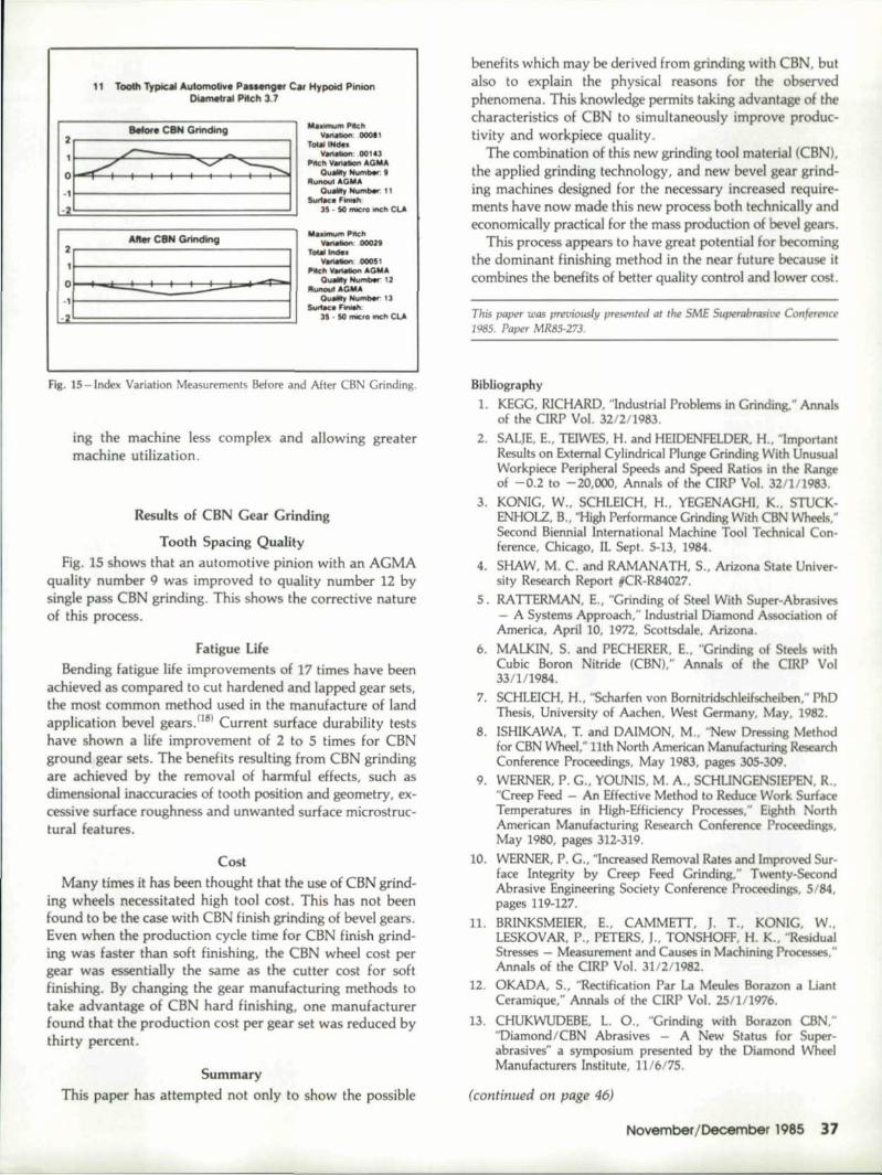
11 TOoUIT~lIk.tll luI_live PUHng:er Ca.r Hypoid PinionDia~,aI P1itch3."
M..L1imutn1 P-Ith"_bOni 0001'T_INilb:
'Vall......., 00143IP1Ic""'_oI!GllloI!
QulO!!!yHum,*, "'Run"". ,"'GM'"
'OIlIO!!!yHu",-'"s...fOA~ml>_
35 • 50 ,"""'" ""'" C!.A
:~tz:,,~tt8I
A_fte!rCBN 'Grinding2.----~-.,11-------------~
MbimumPiKti'1'-..00029
ToW_._0005,
!'1IcII,_.t.C;Mil0..-, .............2
_-' ...GMA,0"""",,_'3,SVrl.cJIi F:'iniIl1c
U • 50 ,mIc'D """h CL.A
Fig. 15 -rod x Variation Measu rements Before and After CBN Griodi ng.
ing the machine less complex and allowing greatermachine utilization,
Results of CBN Gear GrLnding
Tooth Spacing QualityFig. 15 shows that an automotive pinion with an AGMA
quality number 9 was improved to quality number 12 bysingle pass CBN grinding. This shows the corrective natureof this process.
Fatigue LifeBending fatigue life improvements of 17 times have been
achieved as compared to cut hardened and lapped gear sets,the most common method used in the manufacture of [andapplication bevel gears. (18) Current surface durability testshave shown a life improvement of 2to 5 times for CBNground gear sets. The benefits resulting from CBN grindingare achieved by the removal of harmful effects, such asdimensional. inaccuracies of tooth position and geometry, ex-cessive surface roughness and unwanted surface rnicrostruc-tural features.
CostMany times it has been thought that the use of CBN grind-
ing wheels necessitated high tool cost. This has not beenfound to be the case with CBN finish grinding of bevel gears.Even when the production cycle time for CBN finish grind-ing was faster than soft finishing, 'the CBN wheel cost pergear was essentially the same as the cutter cost for softfinishing, By changing the gear manufacturing methods totake advantage of CBN hard finishing,. 'one manufacturerfound that the production cost per gear set was reduced bythirty percent.
SummaryThis paper has attempted not only to show the possible
benefits which may be derived from grinding w.ith CBN, butalso to explain the physical reasons for the observedphenomena. This knowledge permits taking advantage of thecharacteristics of CBN to simultaneously improve produc-tivity and workpiece quality.
The combination of this new grinding tool material (CBN),the applied grinding technology, and new bevel gear grind-ing machines designed for the necessary increas -d require-ments have now mad this new process both technically andeconomically practical for the mass production of bevel gears.
This process appears to have great potentia] for becomingthe dominant finishing method in the near future because itcombines the benefits of better quality control and lower cost.
This paper was pn?Viously presented at the SME Supera.brasilJl? COnfI!TCtlCI?2985. Paper MR85-273.
Bibliography
1, KEGG, RICHARD, "lndustri ,IProblems in Grinding," Annalsof the ClRP Vol. 3212/1983.
2. SALlE, E., TEfWES, H. and HEIDENFELDER, H" "lmportantResults on External Cylindrical Plunge Grincling With UnusualWorkpiece Peripheral Speeds and Speed Ratios in the Rangeof -0.2 to -20,000, Annals of 'the ClRP Vol. 32/111983.
3. KONIG, W" SCHLEICH, H., YEGENA:GHI, K., STUCK-ENHOLZ, B., "High Performance Grinding With CBN V'Yheels.·Second Biennial International Machine Tool Technical Con-ference, Chicago, IL Sept. 5-13, 1984.
4. SHAW, M. C. and RAMANATH, S., Arizona State Univer-sity Research Report HCR-RS4Q27.
5. RATTERMAN, E.. "Grinding of Steel With Super-Abrasives- A Systems Approach:' Industrial Diamond Association ofAmerica, April 10, 1972, Scottsdale, Arizona.
,6. MALKIN, S. and PECHERER, E., "Grinding of Steel. withCubic Boron Nitride (CBN):' Annals of the ClRP Vo]33/111984.
7. SCHlEICH, H., "Scharfen von Bomitridschleifscheiben," PhDThesis, University of Aachen, West Germany, May, 1982.
8, ISHIKAWA, T. and DAIMON, M" "New Dressing Melnodfor CBN Wheel," 11th North American Manufacturing ResearchConference Proceedings, May 1983, pages 305-309.
9. WERNER, P. G" YOUNIS, M, A., SCHLINGENSIEPEN, R.,"Creep Feed - An Effectiv Method ItoReduce Work SurfaceTemperatures in High-Efficiency Processes," Eighth NorthAmerican Ma_nuJactu~Lng Research Conference Proceedings,May 1980, pages 312-319.
10. WERNER, P. G., "Increased Removal Rates and Improved Sur-face Integrity by Creep Feed Grinding," Twenty-SecondAbrasive Engineering Society Conference Proceedings, 5/84,pages 119-127.
11, BRINKSMElER,E., CAMMEIT, 1. T., KONIG, W"LESKOVAR, P., PETERS, J., TONSHOFF, H. K., "ResidualStresses - Measurement and Causes in Machining Processes,"Annals of the CIRP Vol. 31/2/1982,
12. OKADA, 5., "Rectlfication Par La Meules Bcrazcn a LianlCeramique," Annals of the elRP Vol. 25/]/1976,
13. CHUKWUDEBE, L. 0., "Grinding with Borazon CBN,""Diamond/CBN Abrasives - A New Status for Super-abrasives" a symposium presented by the Diamond WheelManufacturers Institute, 11/6175,
(continued on page 46)
NovemberjDecemoef 1985 37

J
1. eNC Gew Shopong "'tell,..2. Shapw Cufter Wllh Miounl.!Jtg ~ ...3. PiCk iI/'IO IPltal LOiI!d'It'Ann• Culler SI<>r_ Magu .... RUl\i5. .!lrive M"lor ·IorChango,6 M~ri. R1rig rOt Wi;lfkpHltB
Fig. 13A &. B - Automatic cutter changing unitwithstorage for 3 cutters.
and tools, The conventional first andsecond generation modern gear shapingmachines are, most likely, not suitablefor an FMS or FMC system. Manymanufacturers say the state-of-the-artgear shaping machine is not ready for in-stallation in an fMS or FMC manufac-turing technique. Most certainly, thethird generation spindle relief CNC gearshapers can, indeed, fuHiIl all designparameters needed for installation in anFMS and FMC applications, namelybecause ofthei.r special fe.atures, i.e.:• zero setup time - automatic
machine setup- too] offset compensation• fully automatic fixture change- fully automatic tool change-gear cutting flexibility - multiple
gear cuttings per setup, i.e. dustergears
• integration of a CNC post processgaugingunittothe CNC control ofthe shaper
46 Gear Technology
IE-5 ON READER REPLY CARD
FUNDAMENTALS OF CBN BEVEL ••.(continued from page 37)
14. STOKES, R. J.. VALENTINE, T. J.,'Wear Mechanisms o.f ABN Abrasive,"Industrial Diamond Review 1984, Vol 44(500-1) pages 34-44.
15. ALTHAUS, P., 'Workpiece ResidualStresses - A Comparison Between CBNand Corundum Abrasives in InternalGrinding," lndustrie DiamanteenRundschau 1983 Vol 17 (4) pages 184-190(Oct-Dec) in German.
16. PETER, J., "Contribution at CIRPResearch to Industrial Problems inGrinding," Annals of the CIRP Vol3312/1984.
17 .. LINDSAY, R., "Principles of Grinding,Four Years Later," SME paper No.MR75-604:.
18. KlMMET, G. J. and DODD, H. D.,"CBN Finish Grinding of HardenedSpiral Bevel and Hypoid Gears," AGMI\.Fall. Technical Meeting, October 14-17,1984.
19. SHAW, M. C, "Fundamentals ofGrinding," Keynote Paper II, NewDevelopments in Grinding, Proceedingsof the International Grinding Con-ference, Pittsburgh, Pennsylvania, April18-20, 1972.
20. !'v1.ALKIN5., COOK, N. H., 'The Wearor Grinding \Nheels, Part 1 AttritiousWear," Transacnons of the ASME,11/71, pgs 1120-1128 ..
21. DEVRIES, R. c.. "Cubic Boron Nitride:Handbook of Properties," General Elec-tric Company; Report No. 72CRD178,June 1972.
22. VANVLACK, L., "Elements of MaterialsScience and Engineering," fourth edition,Addison-Wesley Pu..blishing Co.
23. TORRANCE, A.A... STOKES, R.J.,HOWES, T. D., 'The Effect of GrindingConditions on Rolling Contact FatigueLife of Bearing Steel," MechanicalEngineering, October 1983, pages 63-73.
24. MASY, L., "Machining Technology forHigh Nickel and High Cobalt Alloys andTitanium Alloys," Revue M, Vol. 26,No.4 (in French).
25. SNOEYS, R., MARIS, M., PETERS, j.,"Thermally Induced Damage inGrinding," Annals of the CIRP Vol.2712/1978, page 571.
26. BEllOWS, G., "Low Stress Grinding,"Metcut Research Associates lnc., Aug.1978.
27.. SNOEYS, R., "Residual StI'fSS in Cylin-drical Specimen," data received in privatediscussion at Leuven, Bel'gium.
28. RENKER. H., "Residual Stress ResultingFrom Machining in Surfaoe Layers QfWorkpieces," Industrial and ProductionEngineering, 1-1983, pages. 73-75.
29. TONSHOFF, H. K., "Comparison ofResidual Stress Measured by- the X-R.ayand the Deflection Method on GroundBall Bearing Stee!," Field SymPQsium,June 19, 198.2.
30. KRENZER, T. J. "Computer Aided Cor-rective Machine Settings for Manufactur-ing Bevel and Hypoid Gear Sets,"AG!'v1.Apaper No. 84ITM4.
E-3 ON READER REPLY CARD

![ATR ITALIA GRINDING MACHINES. TECHNOLOGICAL LINES Grinding with conventional abrasives [Al 2 O 3 ] Grinding with superabrasives [CBN]](https://img.pdfslide.net/doc/110x75/5519f0e655034646588b4683/atr-italia-grinding-machines-technological-lines-grinding-with-conventional-abrasives-al-2-o-3-grinding-with-superabrasives-cbn.jpg)